US9497717B2 - Out-of-band acknowledgement of wireless communication - Google Patents
Out-of-band acknowledgement of wireless communicationDownload PDFInfo
- Publication number
- US9497717B2 US9497717B2US14/286,854US201414286854AUS9497717B2US 9497717 B2US9497717 B2US 9497717B2US 201414286854 AUS201414286854 AUS 201414286854AUS 9497717 B2US9497717 B2US 9497717B2
- Authority
- US
- United States
- Prior art keywords
- frequencies
- band
- communication
- radio circuit
- circuit
- Prior art date
- Legal status (The legal status is an assumption and is not a legal conclusion. Google has not performed a legal analysis and makes no representation as to the accuracy of the status listed.)
- Active, expires
Links
Images


Classifications
- H—ELECTRICITY
- H04—ELECTRIC COMMUNICATION TECHNIQUE
- H04W—WIRELESS COMMUNICATION NETWORKS
- H04W56/00—Synchronisation arrangements
- H04W56/0005—Synchronisation arrangements synchronizing of arrival of multiple uplinks
- H—ELECTRICITY
- H04—ELECTRIC COMMUNICATION TECHNIQUE
- H04L—TRANSMISSION OF DIGITAL INFORMATION, e.g. TELEGRAPHIC COMMUNICATION
- H04L1/00—Arrangements for detecting or preventing errors in the information received
- H04L1/12—Arrangements for detecting or preventing errors in the information received by using return channel
- H—ELECTRICITY
- H04—ELECTRIC COMMUNICATION TECHNIQUE
- H04W—WIRELESS COMMUNICATION NETWORKS
- H04W52/00—Power management, e.g. Transmission Power Control [TPC] or power classes
- H04W52/02—Power saving arrangements
- H04W52/0209—Power saving arrangements in terminal devices
- H04W52/0212—Power saving arrangements in terminal devices managed by the network, e.g. network or access point is leader and terminal is follower
- H—ELECTRICITY
- H04—ELECTRIC COMMUNICATION TECHNIQUE
- H04W—WIRELESS COMMUNICATION NETWORKS
- H04W52/00—Power management, e.g. Transmission Power Control [TPC] or power classes
- H04W52/02—Power saving arrangements
- H04W52/0209—Power saving arrangements in terminal devices
- H04W52/0225—Power saving arrangements in terminal devices using monitoring of external events, e.g. the presence of a signal
- H04W52/0229—Power saving arrangements in terminal devices using monitoring of external events, e.g. the presence of a signal where the received signal is a wanted signal
- H—ELECTRICITY
- H04—ELECTRIC COMMUNICATION TECHNIQUE
- H04L—TRANSMISSION OF DIGITAL INFORMATION, e.g. TELEGRAPHIC COMMUNICATION
- H04L1/00—Arrangements for detecting or preventing errors in the information received
- H04L1/12—Arrangements for detecting or preventing errors in the information received by using return channel
- H04L1/16—Arrangements for detecting or preventing errors in the information received by using return channel in which the return channel carries supervisory signals, e.g. repetition request signals
- H04L1/1607—Details of the supervisory signal
- H—ELECTRICITY
- H04—ELECTRIC COMMUNICATION TECHNIQUE
- H04W—WIRELESS COMMUNICATION NETWORKS
- H04W74/00—Wireless channel access
- H04W74/002—Transmission of channel access control information
- H04W74/006—Transmission of channel access control information in the downlink, i.e. towards the terminal
- H—ELECTRICITY
- H04—ELECTRIC COMMUNICATION TECHNIQUE
- H04W—WIRELESS COMMUNICATION NETWORKS
- H04W74/00—Wireless channel access
- H04W74/04—Scheduled access
- H—ELECTRICITY
- H04—ELECTRIC COMMUNICATION TECHNIQUE
- H04W—WIRELESS COMMUNICATION NETWORKS
- H04W74/00—Wireless channel access
- H04W74/08—Non-scheduled access, e.g. ALOHA
- H04W74/0833—Random access procedures, e.g. with 4-step access
- H—ELECTRICITY
- H04—ELECTRIC COMMUNICATION TECHNIQUE
- H04W—WIRELESS COMMUNICATION NETWORKS
- H04W88/00—Devices specially adapted for wireless communication networks, e.g. terminals, base stations or access point devices
- H04W88/02—Terminal devices
- H04W88/06—Terminal devices adapted for operation in multiple networks or having at least two operational modes, e.g. multi-mode terminals
- Y—GENERAL TAGGING OF NEW TECHNOLOGICAL DEVELOPMENTS; GENERAL TAGGING OF CROSS-SECTIONAL TECHNOLOGIES SPANNING OVER SEVERAL SECTIONS OF THE IPC; TECHNICAL SUBJECTS COVERED BY FORMER USPC CROSS-REFERENCE ART COLLECTIONS [XRACs] AND DIGESTS
- Y02—TECHNOLOGIES OR APPLICATIONS FOR MITIGATION OR ADAPTATION AGAINST CLIMATE CHANGE
- Y02D—CLIMATE CHANGE MITIGATION TECHNOLOGIES IN INFORMATION AND COMMUNICATION TECHNOLOGIES [ICT], I.E. INFORMATION AND COMMUNICATION TECHNOLOGIES AIMING AT THE REDUCTION OF THEIR OWN ENERGY USE
- Y02D30/00—Reducing energy consumption in communication networks
- Y02D30/70—Reducing energy consumption in communication networks in wireless communication networks
Definitions
- the described embodimentsrelate to techniques for communicating information in a wireless network.
- the described embodimentsrelate to techniques for providing feedback about communication in one band of frequencies through a different band of frequencies.
- these electronic devicesare capable of wirelessly communicating with other electronic devices.
- these electronic devicescan include a networking subsystem that implements a network interface for: a cellular network (UMTS, LTE, etc.), a wireless local area network (e.g., a wireless network such as described in the Institute of Electrical and Electronics Engineers (IEEE) 802.11 standard or BluetoothTM from the Bluetooth Special Interest Group of Kirkland, Wash.), and/or another type of wireless network.
- UMTScellular network
- LTELong Term Evolution
- IEEEInstitute of Electrical and Electronics Engineers
- BluetoothTMBluetooth Special Interest Group of Kirkland, Wash.
- networking subsystems based on the IEEE 802.11 standardstypically have high power consumption. Because power amplifiers that are used to transmit signals are less efficient at 60 GHz, the power consumption associated with IEEE 802.11ad is expected to be even higher. This additional power consumption may be a challenge in portable electronic devices (such as cellular telephones) in which battery life is already a concern and, thus, may restrict use of the additional band of frequencies.
- the described embodimentsinclude a transmitting device that includes: an antenna; and an interface circuit that communicates with a receiving device.
- the interface circuittransmits a data packet to the receiving device in a first band of frequencies; and receives feedback from the receiving device about the communication of the data packet in a second band of frequencies that is different than the first band of frequencies.
- the transmitting in the first band of frequencies and the receiving in the second band of frequenciesinvolve separate radio circuits in the interface circuit, and the transmitting in the first band of frequencies and the receiving in the second band of frequencies involve different physical layer communication protocols.
- the feedbackmay include a channel-access procedure.
- the channel-access proceduremay include conflict-avoidance information for communication in the second band of frequencies.
- communicating the feedbackmay involve scheduled access or random access to the second band of frequencies (e.g., a contention-based protocol such as listen before talk).
- the transmitting in the first band of frequenciesmay be synchronized with the transmitting in the second band of frequencies so that the data packet is transmitted when transmitting in the second band of frequencies is enabled.
- the second band of frequenciesmay include interference sources during communication between the transmitting device and the receiving device
- the first band of frequenciesmay exclude the interference sources during communication between the transmitting device and the receiving device.
- frequencies in the first band of frequenciesare higher than frequencies in the second band of frequencies.
- This communication circuitincludes: a node that can couple to an antenna; and an interface circuit. This communication circuit may perform operations performed by the transmitting device.
- Another embodimentprovides a method for communicating between the transmitting device and the receiving device. This method includes at least some of the operations performed by the transmitting device.
- the receiving devicethat includes: an antenna; and an interface circuit that communicates with the transmitting device.
- the interface circuitreceives the data packet from the transmitting device in the first band of frequencies; and transmits the feedback to the transmitting device about the communication of the data packet in the second band of frequencies that is different than the first band of frequencies.
- the receiving in the first band of frequencies and the transmitting in the second band of frequenciesinvolve separate radio circuits in the interface circuit, and the receiving in the first band of frequencies and the transmitting in the second band of frequencies involve different physical layer communication protocols.
- This communication circuitincludes: a node that can couple to an antenna; and an interface circuit. This communication circuit may perform operations performed by the receiving device.
- Another embodimentprovides a method for communicating between the transmitting device and the receiving device. This method includes at least some of the operations performed by the receiving device.
- FIG. 1is a block diagram illustrating electronic devices wirelessly communicating in accordance with embodiments of the present disclosure.
- FIG. 2is a flow diagram illustrating a method for communicating between a transmitting device and a receiving device during communication among the electronic devices in FIG. 1 in accordance with embodiments of the present disclosure.
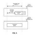
- FIG. 3is a flow diagram illustrating a method for communicating between a transmitting device and a receiving device during communication among the electronic devices in FIG. 1 in accordance with embodiments of the present disclosure.
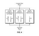
- FIG. 4is a drawing illustrating out-of-band acknowledgment of communication among the electronic devices in FIG. 1 in accordance with embodiments of the present disclosure.
- FIG. 5is a timing diagram illustrating synchronization of communication in two bands of frequencies during communication among the electronic devices in FIG. 1 in accordance with embodiments of the present disclosure.
- FIG. 6is a drawing illustrating communication among the electronic devices in FIG. 1 in accordance with embodiments of the present disclosure.
- FIG. 7is a block diagram illustrating one of the electronic devices of FIG. 1 in accordance with embodiments of the present disclosure.
- FIG. 8is a block diagram illustrating a communication circuit for use in the one of the electronic devices in FIG. 1 in accordance with embodiments of the present disclosure.
- Power consumption in a receiving deviceis avoided by receiving packets from a transmitting device in a first band of frequencies (such as around 60 GHz) and providing acknowledgments in a second band of frequencies that is different than the first band of frequencies (such as around 5 GHz). These out-of-band acknowledgments may allow the receiving device to avoid transmissions in the first band of frequencies and the associated power consumption. Moreover, the transmissions by the transmitting device in the first band of frequencies and the second band of frequencies may be synchronized so that packets are transmitted in the first band of frequencies when transmission in the second band of frequencies is enabled. By reducing the power consumption of the receiving device while offering the added capacity and throughput associated with the first band of frequencies, this communication technique may improve the performance of the transmitting device and the receiving device, and thus may improve the user experience when using the transmitting device and/or the receiving device.
- the transmitting and the receiving devicesinclude radios that communicate packets in accordance with a communication protocol, such as an Institute of Electrical and Electronics Engineers (IEEE) 802.11 standard (which is sometimes referred to as ‘Wi-Fi®,’ from the Wi-Fi Alliance of Austin, Tex.), Bluetooth (from the Bluetooth Special Interest Group of Kirkland, Wash.), and/or another type of wireless interface.
- IEEE 802.11an Institute of Electrical and Electronics Engineers 802.11 standard
- Wi-Fi®which is sometimes referred to as ‘Wi-Fi®,’ from the Wi-Fi Alliance of Austin, Tex.
- Bluetoothfrom the Bluetooth Special Interest Group of Kirkland, Wash.
- FIG. 1presents a block diagram illustrating transmitting device 110 (such as an access point) and one or more receiving devices 112 (such as portable electronic devices, e.g., cellular telephones) wirelessly communicating.
- these electronic devicesmay wirelessly communicate while: transmitting advertising frames on wireless channels, detecting one another by scanning wireless channels, establishing connections (for example, by transmitting association requests), and/or transmitting and receiving packets (which may include the association requests, feedback about the communication and/or additional information as payloads).
- transmitting device 110 and the one or more receiving devices 112may include subsystems, such as a networking subsystem, a memory subsystem and a processor subsystem.
- transmitting device 110 and the one or more receiving devices 112may include radios 114 in the networking subsystems. More generally, transmitting device 110 and the one or more receiving devices 112 can include (or can be included within) any electronic devices with the networking subsystems that enable transmitting device 110 and the one or more receiving devices 112 to wirelessly communicate with each other.
- This wireless communicationcan comprise transmitting advertisements on wireless channels to enable electronic devices to make initial contact or detect each other, followed by exchanging subsequent data/management frames (such as association requests and responses) to establish a connection, configure security options (e.g., Internet Protocol Security), transmit and receive packets or frames via the connection, etc.
- security optionse.g., Internet Protocol Security
- wireless signals 116are transmitted from a radio 114 - 1 in transmitting device 110 . These wireless signals 116 are received by radios 114 in the one or more receiving devices 112 .
- transmitting device 110may transmit packets. In turn, these packets may be received by at least the one of receiving devices 112 . This may allow transmitting device 110 to communicate information to receiving devices 112 .
- the communication between transmitting device 110 and a given one of receiving devices 112may be characterized by a variety of performance metrics, such as: a data rate, a data rate for successful communication (which is sometimes referred to as a ‘throughput’), an error rate (such as a retry or resend rate), a mean-square error of equalized signals relative to an equalization target, intersymbol interference, multipath interference, a signal-to-noise ratio, a width of an eye pattern, a ratio of number of bytes successfully communicated during a time interval (such as 1-10 s) to an estimated maximum number of bytes that can be communicated in the time interval (the latter of which is sometimes referred to as the ‘capacity’ of a communication channel or link), and/or a ratio of an actual data rate to an estimated data rate (which is sometimes referred to as ‘utilization’).
- the communication between transmitting device 110 and a given one of receiving devices 112may be characterized by a variety of performance metrics, such as:
- the networking subsystems in transmitting device 110 and the one or more receiving devices 112may be configured to communicate information (such as packets) in a first band of frequencies and a second band of frequencies.
- these bands of frequenciesmay or may not be continuous (e.g., a given band of frequencies may include multiple channels that may or may not be contiguous), and may or may not overlap (at least in part) each other.
- the bands of frequenciesare different (i.e., do not overlap) and the first band of frequencies is higher than the second band of frequencies (e.g., the center frequency in the first band of frequencies is higher than the center frequency in the second band of frequencies).
- the first band of frequenciesmay be a so-called 60 GHz band of frequencies and the second band of frequencies may be a so-called 5 GHz band of frequencies.
- the communication techniquemay be used with other bands of frequencies (e.g., separately or in conjunction with the 5 GHz band of frequencies, the second band of frequencies may include a so-called 2.4 GHz band).
- transmitting device 110may transmit packets to the one or more receiving devices 112 using the first band of frequencies and the second band of frequencies.
- a given one of receiving devices 112may receive packets in the first band of frequencies and the second band of frequencies, but may only transmit packets using the second band of frequencies.
- receiving device 112 - 1may transmit an acknowledgment (and, more generally, feedback about the communication) to transmitting device 110 in the second band of frequencies (i.e., using out-of-band communication).
- acknowledgmentand, more generally, feedback about the communication
- transmitting device 110in the second band of frequencies (i.e., using out-of-band communication).
- transmissions in the first band of frequencies and the second band of frequenciesmay be synchronized (i.e., transmitting of packets in the first band of frequencies may occur when transmitting in the second band of frequencies is enabled).
- the second band of frequenciesmay be used to manage the communication in the first band of frequencies.
- the second band of frequenciesmay be used to convey (i.e., via bidirectional communication) basic-service-set operations, such as probe, association and authentication messages, and thus may be used to establish a connection or association between transmitting device 110 and a given one of receiving devices 112 .
- the second band of frequenciesmay be used to convey control or action frames, such as beamforming or beam-pattern information (which may be used to determine beam-pattern settings for a set of antennas in transmitting device 110 and/or a given one of receiving devices 112 ), conflict-avoidance information for communication in the first band of frequencies and/or the second band of frequencies and, more generally, information associated with a channel-access procedure.
- control or action framessuch as beamforming or beam-pattern information (which may be used to determine beam-pattern settings for a set of antennas in transmitting device 110 and/or a given one of receiving devices 112 ), conflict-avoidance information for communication in the first band of frequencies and/or the second band of frequencies and, more generally, information associated with a channel-access procedure.
- the first band of frequenciesmay be used for unidirectional communication of packets from transmitting device 110 to the one or more receiving devices 112 .
- the first band of frequenciesmay not convey the information associated with the channel-access procedure between transmitting device 110 and a given one of receiving devices 112 (such as messages that specify a backoff time or a channel access time during communication).
- the first band of frequenciesis higher than the second band of frequencies.
- the second band of frequenciesmay represent a more congested environment than the first band of frequencies.
- the first band of frequenciesmay involve line-of-sight communication between transmitting device 110 and a given one of receiving devices 112 .
- the second band of frequenciesmay include interference sources during communication between transmitting device 110 and the given one of receiving devices 112 , and the first band of frequencies may exclude these interference sources.
- the transmitting in the first band of frequencies and the receiving in the second band of frequenciesmay involve separate radio circuits in radio 114 - 1 in transmitting device 110 , as well as different physical layer communication protocols.
- the transmittingmay involve IEEE 802.11ad and the receiving may involve another IEEE 802.11-compatible communication protocol.
- the receiving in the first band of frequencies and the transmitting in the second band of frequenciesmay involve separate radio circuits in radios 114 , as well as the different physical layer communication protocols.
- the receivingmay involve IEEE 802.11ad and the transmitting may involve the other IEEE 802.11-compatible communication protocol.
- processing a packet or frame in transmitting device 110 and/or receiving devices 112includes: receiving wireless signals 116 with the packet or frame; decoding/extracting the packet or frame from received wireless signals 116 to acquire the packet or frame; and processing the packet or frame to determine information contained in the packet or frame (such as the feedback, etc.).
- FIG. 1Although we describe the network environment shown in FIG. 1 as an example, in alternative embodiments, different numbers or types of electronic devices may be present. For example, some embodiments comprise more or fewer electronic devices. As another example, in another embodiment, different electronic devices are transmitting and/or receiving packets or frames.
- FIG. 2presents a flow diagram illustrating method 200 for communicating between a transmitting device and a receiving device, which may be implemented by the transmitting device and/or a communication circuit in the transmitting device.
- the transmitting devicemay be transmitting device 110 ( FIG. 1 ).
- the transmitting devicetransmits a data packet (operation 210 ) to the receiving device in the first band of frequencies. Then, the transmitting device receives feedback from the receiving device (operation 212 ) about communication of the data packet in the second band of frequencies that is different than the first band of frequencies.
- FIG. 3presents a flow diagram illustrating method 300 for communicating between the transmitting device and the receiving device, which may be implemented by the receiving device and/or a communication circuit in the receiving device.
- the receiving devicemay be one of receiving devices 112 ( FIG. 1 ).
- the receiving devicereceives the data packet (operation 310 ) from the transmitting device in the first band of frequencies. Then, the receiving device transmits the feedback to the transmitting device (operation 312 ) about communication of the data packet in the second band of frequencies that is different than the first band of frequencies.
- the transmitting devicemay facilitate high capacity or high throughput communication with the receiving device, while reducing the power consumption of the receiving device. Consequently, this communication technique may facilitate high performance communication between the transmitting device and the receiving device.
- methods 200 ( FIG. 2 ) and/or 300there may be additional or fewer operations. Additionally, the order of the operations in methods 200 ( FIG. 2 ) and/or 300 may be changed, and/or two or more operations may be combined into a single operation. Note that communicating the feedback in method 200 ( FIG. 2 ) and/or 300 may involve scheduled access or random access to the second band of frequencies (e.g., a contention-based protocol such as listen before talk).
- a contention-based protocolsuch as listen before talk
- Wi-Fi operating in the 5 GHz band of frequenciesis augmented using Wi-Fi operating in the unlicensed 60 GHz band of frequencies or spectrum.
- existing approachesinvolve running a complete Wi-Fi basic service set in the 60 GHz spectrum.
- the disclosed communication techniqueprovides a simpler, cheaper and lower power-consumption alternative for portable electronic devices.
- the 60 GHz spectrumis used as a downlink-only ‘extension’ channel to a primary basic service set in the 5 GHz band of frequencies.
- This 5 GHz channelmay be used to communicate IEEE 802.11 media-access-control information (such as clear channel assessment, acknowledgment, beamforming information or feedback, etc.), while the 60 GHz spectrum is used in an opportunistic fashion to augment the capacity of the 5 GHz channel (e.g., use of the 60 GHz spectrum may be selectively enabled as needed based on the amount of data to be communicated, performance of the 5 GHz channel, etc.).
- the communication techniquedoes not require that a portable electronic device (such as one of receiving devices 112 in FIG. 1 ) transmit radio signals in the 60 GHz spectrum, which can result in substantial power savings.
- FIG. 4presents a drawing showing out-of-band acknowledgment (in 5 GHz band of frequencies) of communication in the 60 GHz band of frequencies between transmitting device 110 and receiving device 112 - 1 (which is used as an illustrative example).
- the optional 2.4 GHz band of frequencies and the 5 GHz band of frequenciesmay be used for transmitting (Tx) and receiving (Rx), while the 60 GHz band of frequencies may be used for receiving at receiving device 112 - 1 .
- the channel access time prior to transmitting one or more packetsmay vary from 100 ⁇ s to around 10 ms.
- the 60 GHz band of frequenciesis less crowded than the 5 GHz band of frequencies and may exclude the interference sources. This may result in shorter channel access times.
- the high capacity and data rates associated with the 60 GHz band of frequenciesmay result in short transmit times.
- the radio circuits and memory(such as first-in first-out buffers) associated with the 5 GHz band of frequencies and the 60 GHz band of frequencies may be synchronized.
- the clocks associated with these radio circuitsmay be synchronized so that transmission of data in the 60 GHz band of frequencies occurs when transmission in the 5 GHz band of frequencies is enabled.
- thisallows emptying of the memory buffer for the 5 GHz and the 60 GHz bands to be synchronized, and allows a common acknowledgement message to be used for both the 5 GHz and the 60 GHz bands.
- FIG. 5presents a timing diagram illustrating synchronization of the communication in two bands of frequencies, including the out-of band acknowledgment (ACK) of the data transmitted in the 60 GHz band of frequencies communicated in the 5 GHz band of frequencies.
- ACKout-of band acknowledgment
- FIG. 6presents a drawing illustrating communication between transmitting device 110 and one of receiving devices 112 in FIG. 1 (such as receiving device 112 - 1 ).
- transmitting device 110may provide a data packet 610 to receiving device 112 - 1 via the first band of frequencies.
- receiving device 112 - 1may provide feedback 612 (such as an acknowledgment or a block acknowledgment) to transmitting device 110 via the second band of frequencies.
- FIG. 7presents a block diagram illustrating an electronic device 700 , such as transmitting device 110 or one of receiving devices 112 in FIG. 1 .
- This electronic deviceincludes processing subsystem 710 , memory subsystem 712 , and networking subsystem 714 .
- Processing subsystem 710includes one or more devices configured to perform computational operations.
- processing subsystem 710can include one or more microprocessors, application-specific integrated circuits (ASICs), microcontrollers, programmable-logic devices, and/or one or more digital signal processors (DSPs).
- ASICsapplication-specific integrated circuits
- DSPsdigital signal processors
- Memory subsystem 712includes one or more devices for storing data and/or instructions for processing subsystem 710 and networking subsystem 714 .
- memory subsystem 712can include dynamic random access memory (DRAM), static random access memory (SRAM), and/or other types of memory.
- instructions for processing subsystem 710 in memory subsystem 712include: one or more program modules or sets of instructions (such as program module 722 or operating system 724 ), which may be executed by processing subsystem 710 .
- the one or more computer programsmay constitute a computer-program mechanism.
- instructions in the various modules in memory subsystem 712may be implemented in: a high-level procedural language, an object-oriented programming language, and/or in an assembly or machine language.
- the programming languagemay be compiled or interpreted, e.g., configurable or configured (which may be used interchangeably in this discussion), to be executed by processing subsystem 710 .
- memory subsystem 712can include mechanisms for controlling access to the memory.
- memory subsystem 712includes a memory hierarchy that comprises one or more caches coupled to a memory in electronic device 700 .
- one or more of the cachesis located in processing subsystem 710 .
- memory subsystem 712is coupled to one or more high-capacity mass-storage devices (not shown).
- memory subsystem 712can be coupled to a magnetic or optical drive, a solid-state drive, or another type of mass-storage device.
- memory subsystem 712can be used by electronic device 700 as fast-access storage for often-used data, while the mass-storage device is used to store less frequently used data.
- Networking subsystem 714includes one or more devices configured to couple to and communicate on a wired and/or wireless network (i.e., to perform network operations), including: control logic 716 , an interface circuit 718 and a set of antennas 720 .
- networking subsystem 714can include a Bluetooth networking system, a cellular networking system (e.g., a 3G/4G network such as UMTS, LTE, etc.), a universal serial bus (USB) networking system, a networking system based on the standards described in IEEE 802.11 (e.g., a Wi-Fi networking system), an Ethernet networking system, and/or another networking system.
- set of antennas 720includes multiple antenna elements in an adaptive array that can be selectively turned on and/or off by control logic 716 to create a variety of antenna patterns.
- Networking subsystem 714includes processors, controllers, radios or radio circuits (which communicate information using electromagnetic waves in the radio and/or microwave portions of the electromagnetic spectrum), power amplifier, antennas, sockets, plugs, and/or other devices used for coupling to, communicating on, and handling data and events for each supported networking system.
- processors, controllers, radios or radio circuitswhich communicate information using electromagnetic waves in the radio and/or microwave portions of the electromagnetic spectrum
- power amplifierantennas, sockets, plugs, and/or other devices used for coupling to, communicating on, and handling data and events for each supported networking system.
- mechanisms used for coupling to, communicating on, and handling data and events on the network for each network systemare sometimes collectively referred to as a ‘network interface’ for the network system.
- a ‘network’ or a ‘connection’ between the electronic devicesdoes not yet exist. Therefore, electronic device 700 may use the mechanisms in networking subsystem 714 for performing simple wireless communication between the electronic devices, e.g., transmitting advertising or beacon frames and/or scanning
- Bus 728may include an electrical, optical, and/or electro-optical connection that the subsystems can use to communicate commands and data among one another. Although only one bus 728 is shown for clarity, different embodiments can include a different number or configuration of electrical, optical, and/or electro-optical connections among the subsystems.
- electronic device 700includes a display subsystem 726 for displaying information on a display, which may include a display driver and the display, such as a liquid-crystal display, a multi-touch touchscreen, etc.
- Electronic device 700can be (or can be included in) any electronic device with at least one network interface.
- electronic device 700can be (or can be included in): a desktop computer, a laptop computer, a subnotebook/netbook, a server, a tablet computer, a smartphone, a cellular telephone, a consumer-electronic device, a portable computing device, an access point, a router, a switch, communication equipment, test equipment, and/or another electronic device.
- electronic device 700may include one or more additional processing subsystems 710 , memory subsystems 712 , networking subsystems 714 , and/or display subsystems 726 . Additionally, one or more of the subsystems may not be present in electronic device 700 . Moreover, in some embodiments, electronic device 700 may include one or more additional subsystems that are not shown in FIG. 7 . Also, although separate subsystems are shown in FIG. 7 , in some embodiments some or all of a given subsystem or component can be integrated into one or more of the other subsystems or component(s) in electronic device 700 . For example, in some embodiments program module 722 is included in operating system 724 and/or control logic 716 is included in interface circuit 718 .
- circuits and components in electronic device 700may be implemented using any combination of analog and/or digital circuitry, including: bipolar, PMOS and/or NMOS gates or transistors.
- signals in these embodimentsmay include digital signals that have approximately discrete values and/or analog signals that have continuous values.
- components and circuitsmay be single-ended or differential, and power supplies may be unipolar or bipolar.
- FIG. 8presents a block diagram of communication circuit 800 .
- communication circuit 800may include: control logic 716 , an interface circuit 718 and set of nodes 810 that can couple to set of antennas 720 ( FIG. 7 ).
- set of nodes 810may include at least one node (such as a pad).
- the integrated circuitmay include hardware and/or software mechanisms that are used for transmitting wireless signals from electronic device 700 and receiving signals at electronic device 700 from other electronic devices.
- transmitting device 110FIG. 1
- transmitting in the first band of frequencies and receiving in the second band of frequenciesmay involve separate radio circuits (as well as different physical layer communication protocols).
- receiving in the first band of frequencies and transmitting in the second band of frequenciesmay involve separate radio circuits (as well as the different physical layer communication protocols).
- radiosare generally known in the art and hence are not described in detail.
- networking subsystem 714 and/or the integrated circuitcan include any number of radios. Note that the radios in multiple-radio embodiments function in a similar way to the described single-radio embodiments.
- networking subsystem 714 and/or the integrated circuitinclude a configuration mechanism (such as one or more hardware and/or software mechanisms) that configures the radio(s) to transmit and/or receive on a given communication channel (e.g., a given carrier frequency).
- a configuration mechanismsuch as one or more hardware and/or software mechanisms
- the configuration mechanismcan be used to switch the radio from monitoring and/or transmitting on a given communication channel to monitoring and/or transmitting on a different communication channel.
- monitoringas used herein comprises receiving signals from other electronic devices and possibly performing one or more processing operations on the received signals, e.g., determining if the received signal comprises an advertising frame, etc.
- an output of a process for designing the integrated circuit, or a portion of the integrated circuit, which includes one or more of the circuits described hereinmay be a computer-readable medium such as, for example, a magnetic tape or an optical or magnetic disk.
- the computer-readable mediummay be encoded with data structures or other information describing circuitry that may be physically instantiated as the integrated circuit or the portion of the integrated circuit.
- data structuresare commonly written in: Caltech Intermediate Format (CIF), Calma GDS II Stream Format (GDSII) or Electronic Design Interchange Format (EDIF).
- the described embodiments of the communication techniquemay be used in a variety of network interfaces.
- some of the operations in the preceding embodimentswere implemented in hardware or software, in general the operations in the preceding embodiments can be implemented in a wide variety of configurations and architectures. Therefore, some or all of the operations in the preceding embodiments may be performed in hardware, in software or both.
- at least some of the operations in the detection techniquemay be implemented using program module 722 , operating system 724 (such as a driver for interface circuit 718 ) or in firmware in interface circuit 718 .
- at least some of the operations in the communication techniquemay be implemented in a physical layer, such as hardware in interface circuit 718 .
- the synchronization between the transmitting in the first band of frequencies and the second band of frequenciesmay be implemented in hardware.
Landscapes
- Engineering & Computer Science (AREA)
- Computer Networks & Wireless Communication (AREA)
- Signal Processing (AREA)
- Mobile Radio Communication Systems (AREA)
Abstract
Description
Claims (30)
Priority Applications (4)
| Application Number | Priority Date | Filing Date | Title |
|---|---|---|---|
| US14/286,854US9497717B2 (en) | 2014-05-23 | 2014-05-23 | Out-of-band acknowledgement of wireless communication |
| EP15795711.9AEP3146768B1 (en) | 2014-05-23 | 2015-05-13 | Out-of-band acknowledgment of wireless communication |
| CN201580039833.1ACN106664655B (en) | 2014-05-23 | 2015-05-13 | Out-of-band acknowledgement for wireless communications |
| PCT/US2015/030573WO2015179189A1 (en) | 2014-05-23 | 2015-05-13 | Out-of-band acknowledgment of wireless communication |
Applications Claiming Priority (1)
| Application Number | Priority Date | Filing Date | Title |
|---|---|---|---|
| US14/286,854US9497717B2 (en) | 2014-05-23 | 2014-05-23 | Out-of-band acknowledgement of wireless communication |
Publications (2)
| Publication Number | Publication Date |
|---|---|
| US20150341879A1 US20150341879A1 (en) | 2015-11-26 |
| US9497717B2true US9497717B2 (en) | 2016-11-15 |
Family
ID=54554553
Family Applications (1)
| Application Number | Title | Priority Date | Filing Date |
|---|---|---|---|
| US14/286,854Active2034-06-02US9497717B2 (en) | 2014-05-23 | 2014-05-23 | Out-of-band acknowledgement of wireless communication |
Country Status (4)
| Country | Link |
|---|---|
| US (1) | US9497717B2 (en) |
| EP (1) | EP3146768B1 (en) |
| CN (1) | CN106664655B (en) |
| WO (1) | WO2015179189A1 (en) |
Families Citing this family (12)
| Publication number | Priority date | Publication date | Assignee | Title |
|---|---|---|---|---|
| US9997830B2 (en) | 2012-05-13 | 2018-06-12 | Amir Keyvan Khandani | Antenna system and method for full duplex wireless transmission with channel phase-based encryption |
| WO2013173250A1 (en) | 2012-05-13 | 2013-11-21 | Invention Mine Llc | Full duplex wireless transmission with self-interference cancellation |
| US10177896B2 (en) | 2013-05-13 | 2019-01-08 | Amir Keyvan Khandani | Methods for training of full-duplex wireless systems |
| US9236996B2 (en) | 2013-11-30 | 2016-01-12 | Amir Keyvan Khandani | Wireless full-duplex system and method using sideband test signals |
| US9820311B2 (en) | 2014-01-30 | 2017-11-14 | Amir Keyvan Khandani | Adapter and associated method for full-duplex wireless communication |
| WO2017081800A1 (en)* | 2015-11-12 | 2017-05-18 | 富士通株式会社 | Terminal device, base station device, wireless communication system, and wireless communication method |
| US10333593B2 (en) | 2016-05-02 | 2019-06-25 | Amir Keyvan Khandani | Systems and methods of antenna design for full-duplex line of sight transmission |
| US20180124700A1 (en)* | 2016-11-01 | 2018-05-03 | Qualcomm Incorporated | Transmit power configuration based on bandwidth |
| US10700766B2 (en) | 2017-04-19 | 2020-06-30 | Amir Keyvan Khandani | Noise cancelling amplify-and-forward (in-band) relay with self-interference cancellation |
| CN109845178B (en)* | 2017-06-16 | 2022-03-08 | Lg电子株式会社 | Method and apparatus for transmitting and receiving wireless signal in wireless communication system |
| US11057204B2 (en) | 2017-10-04 | 2021-07-06 | Amir Keyvan Khandani | Methods for encrypted data communications |
| US11012144B2 (en) | 2018-01-16 | 2021-05-18 | Amir Keyvan Khandani | System and methods for in-band relaying |
Citations (34)
| Publication number | Priority date | Publication date | Assignee | Title |
|---|---|---|---|---|
| US3626382A (en)* | 1969-11-19 | 1971-12-07 | Burroughs Corp | Data processing terminal unit |
| US5847662A (en)* | 1994-12-27 | 1998-12-08 | Kabushiki Kaisha Toshiba | Radio card communication apparatus |
| US6463039B1 (en)* | 1998-04-24 | 2002-10-08 | Intelligent Ideation, Inc. | Method and apparatus for full duplex sideband communication |
| US20020173272A1 (en)* | 2001-03-22 | 2002-11-21 | Ping Liang | Top-level controller for wireless communication devices and protocols |
| US20040125820A1 (en)* | 2002-12-31 | 2004-07-01 | Carlos Rios | Multiprotocol WLAN access point devices |
| US20050083180A1 (en)* | 2000-01-06 | 2005-04-21 | Horwitz Clifford A. | System for multi-standard RFID tags |
| US6915079B1 (en)* | 2000-05-30 | 2005-07-05 | Nortel Networks, Ltd. | Non-return optical star coupler |
| US20050176452A1 (en)* | 2003-02-14 | 2005-08-11 | Perlman Stephen G. | Self-configuring, adaptive, three-dimensional, wireless network |
| US20050256963A1 (en)* | 2002-10-01 | 2005-11-17 | Robert Bosch Gmbh | Wireless local area network with repeater for enhancing network coverage |
| US20060019612A1 (en)* | 2003-01-30 | 2006-01-26 | Matsushita Electric Industrail Co., Ltd. | Radio communication device that meets a plurality of frequency bands |
| US7020277B1 (en)* | 2001-12-05 | 2006-03-28 | Lsi Logic Corporation | DSL line interface having low-pass filter characteristic with reduced external components |
| US7154845B1 (en)* | 2002-05-03 | 2006-12-26 | Cisco Technology, Inc. | Method and system for measuring crosstalk utilizing a crossbar switch |
| US7230541B2 (en)* | 2003-11-19 | 2007-06-12 | Baker Hughes Incorporated | High speed communication for measurement while drilling |
| US7336626B1 (en)* | 2001-09-28 | 2008-02-26 | Arraycomm, Inc | Operating time division duplex (TDD) wireless systems in paired spectrum (FDD) allocations |
| US20080279125A1 (en)* | 2004-03-16 | 2008-11-13 | Ari Hottinen | Method, a Device and a System For Duplex Communications |
| US20080298356A1 (en)* | 2007-05-30 | 2008-12-04 | Silicon Storage Technology Inc. | Systems and methods for wireless transmission and reception of data including frequency and channel code selection |
| US20090029715A1 (en)* | 2006-03-22 | 2009-01-29 | Bernd Burchardt | Method For Determining The Distance Of A Mobile Communication Terminal From Mobile Radio Base Stations, And Mobile Communication Terminal |
| US20090097423A1 (en)* | 2007-10-12 | 2009-04-16 | Samsung Electronics Co., Ltd. | Apparatus and method for transmitting/receiving resource allocation information in a communication system |
| US20090135084A1 (en)* | 2007-11-27 | 2009-05-28 | Chih-Yung Huang | Structure of dual symmetrical antennas |
| US20110080196A1 (en)* | 2009-10-02 | 2011-04-07 | Mstar Semiconductor, Inc. | VCO Control Circuit and Method Thereof, Fast Locking PLL and Method for Fast Locking PLL |
| US20110164538A1 (en)* | 2002-03-11 | 2011-07-07 | Adaptix, Inc. | Spectrum Allocation System and Method for Multi-Band Wireless RF Data Communications |
| US8005038B2 (en)* | 2007-05-30 | 2011-08-23 | Melodytek Limited | Digital display system with media processor and wireless audio |
| US20120164963A1 (en)* | 2007-02-26 | 2012-06-28 | Broadcom Corporation | Method and System for Software Defined Power Amplifier for Multi-Band, Multi-Standard Applications |
| US20120176233A1 (en)* | 2007-10-26 | 2012-07-12 | Measurement Limited | Tire pressure monitoring system using wireless network |
| US20120220244A1 (en)* | 2008-04-04 | 2012-08-30 | Broadcom Corporation | WCDMA transmit architecture |
| US20120243494A1 (en)* | 2002-07-15 | 2012-09-27 | Broadcom Corporation | Communication gateway supporting wlan communications in multiple communication protocols and in multiple frequency bands |
| US8676221B2 (en)* | 2009-06-11 | 2014-03-18 | Qualcomm Incorporated | Multiband antenna for cooperative MIMO |
| US20140081793A1 (en)* | 2003-02-05 | 2014-03-20 | Steven M. Hoffberg | System and method |
| WO2014061998A1 (en) | 2012-10-16 | 2014-04-24 | Samsung Electronics Co., Ltd. | Method and apparatus for performing hybrid automatic repeat request operation in an asymmetric multicarrier communication network environment |
| US20140330992A1 (en)* | 2012-03-21 | 2014-11-06 | Huawei Device Co., Ltd. | USB Device Communication Method, Device and System |
| US20140349608A1 (en)* | 2011-08-29 | 2014-11-27 | Nationz Technologies Inc. | Secure rf communication method, terminal and system |
| US8917697B2 (en)* | 2009-08-18 | 2014-12-23 | Ntt Docomo, Inc. | Radio communication control method, radio base station apparatus and mobile terminal apparatus |
| US20150163808A1 (en)* | 2009-10-16 | 2015-06-11 | Silver Spring Networks, Inc. | Wireless device with opportunistic band access |
| US20150318836A1 (en)* | 2012-02-27 | 2015-11-05 | Intel Mobile Communications GmbH | Second-order filter with notch for use in receivers to effectively suppress the transmitter blockers |
Family Cites Families (6)
| Publication number | Priority date | Publication date | Assignee | Title |
|---|---|---|---|---|
| CN101415275B (en)* | 2007-10-17 | 2013-05-08 | 中兴通讯股份有限公司 | Method and system for inducting outer feedback in TDD aerial interface |
| US8363597B2 (en)* | 2009-04-09 | 2013-01-29 | Qualcomm Incorporated | MAC architectures for wireless communications using multiple physical layers |
| US8737368B2 (en)* | 2010-04-26 | 2014-05-27 | Intel Corporation | Method, apparatus and system for switching traffic streams among multiple frequency bands |
| CN103988546A (en)* | 2011-12-08 | 2014-08-13 | 交互数字专利控股公司 | High speed dual band cellular communication |
| KR101953144B1 (en)* | 2012-03-27 | 2019-02-28 | 에스케이 텔레콤주식회사 | ACCESS POINT SUPPORTING 2.4GHz/5GHz DUAL BAND IN WIRELESS LAN AND ROAD BALANCING METHOD THEREOF |
| KR20140029143A (en)* | 2012-08-31 | 2014-03-10 | 주식회사 케이티 | Method for scanning of access point supporting multi-band and apparatus for performing the method |
- 2014
- 2014-05-23USUS14/286,854patent/US9497717B2/enactiveActive
- 2015
- 2015-05-13EPEP15795711.9Apatent/EP3146768B1/enactiveActive
- 2015-05-13CNCN201580039833.1Apatent/CN106664655B/enactiveActive
- 2015-05-13WOPCT/US2015/030573patent/WO2015179189A1/enactiveApplication Filing
Patent Citations (35)
| Publication number | Priority date | Publication date | Assignee | Title |
|---|---|---|---|---|
| US3626382A (en)* | 1969-11-19 | 1971-12-07 | Burroughs Corp | Data processing terminal unit |
| US5847662A (en)* | 1994-12-27 | 1998-12-08 | Kabushiki Kaisha Toshiba | Radio card communication apparatus |
| US6463039B1 (en)* | 1998-04-24 | 2002-10-08 | Intelligent Ideation, Inc. | Method and apparatus for full duplex sideband communication |
| US20050083180A1 (en)* | 2000-01-06 | 2005-04-21 | Horwitz Clifford A. | System for multi-standard RFID tags |
| US6915079B1 (en)* | 2000-05-30 | 2005-07-05 | Nortel Networks, Ltd. | Non-return optical star coupler |
| US20020173272A1 (en)* | 2001-03-22 | 2002-11-21 | Ping Liang | Top-level controller for wireless communication devices and protocols |
| US7336626B1 (en)* | 2001-09-28 | 2008-02-26 | Arraycomm, Inc | Operating time division duplex (TDD) wireless systems in paired spectrum (FDD) allocations |
| US7020277B1 (en)* | 2001-12-05 | 2006-03-28 | Lsi Logic Corporation | DSL line interface having low-pass filter characteristic with reduced external components |
| US20110164538A1 (en)* | 2002-03-11 | 2011-07-07 | Adaptix, Inc. | Spectrum Allocation System and Method for Multi-Band Wireless RF Data Communications |
| US20140233440A1 (en)* | 2002-03-11 | 2014-08-21 | Netgear, Inc. | Spectrum Allocation System and Method for Multi-Band Wireless RF Data Communications |
| US7154845B1 (en)* | 2002-05-03 | 2006-12-26 | Cisco Technology, Inc. | Method and system for measuring crosstalk utilizing a crossbar switch |
| US20120243494A1 (en)* | 2002-07-15 | 2012-09-27 | Broadcom Corporation | Communication gateway supporting wlan communications in multiple communication protocols and in multiple frequency bands |
| US20050256963A1 (en)* | 2002-10-01 | 2005-11-17 | Robert Bosch Gmbh | Wireless local area network with repeater for enhancing network coverage |
| US20040125820A1 (en)* | 2002-12-31 | 2004-07-01 | Carlos Rios | Multiprotocol WLAN access point devices |
| US20060019612A1 (en)* | 2003-01-30 | 2006-01-26 | Matsushita Electric Industrail Co., Ltd. | Radio communication device that meets a plurality of frequency bands |
| US20140081793A1 (en)* | 2003-02-05 | 2014-03-20 | Steven M. Hoffberg | System and method |
| US20050176452A1 (en)* | 2003-02-14 | 2005-08-11 | Perlman Stephen G. | Self-configuring, adaptive, three-dimensional, wireless network |
| US7230541B2 (en)* | 2003-11-19 | 2007-06-12 | Baker Hughes Incorporated | High speed communication for measurement while drilling |
| US20080279125A1 (en)* | 2004-03-16 | 2008-11-13 | Ari Hottinen | Method, a Device and a System For Duplex Communications |
| US20090029715A1 (en)* | 2006-03-22 | 2009-01-29 | Bernd Burchardt | Method For Determining The Distance Of A Mobile Communication Terminal From Mobile Radio Base Stations, And Mobile Communication Terminal |
| US20120164963A1 (en)* | 2007-02-26 | 2012-06-28 | Broadcom Corporation | Method and System for Software Defined Power Amplifier for Multi-Band, Multi-Standard Applications |
| US8005038B2 (en)* | 2007-05-30 | 2011-08-23 | Melodytek Limited | Digital display system with media processor and wireless audio |
| US20080298356A1 (en)* | 2007-05-30 | 2008-12-04 | Silicon Storage Technology Inc. | Systems and methods for wireless transmission and reception of data including frequency and channel code selection |
| US20090097423A1 (en)* | 2007-10-12 | 2009-04-16 | Samsung Electronics Co., Ltd. | Apparatus and method for transmitting/receiving resource allocation information in a communication system |
| US20120176233A1 (en)* | 2007-10-26 | 2012-07-12 | Measurement Limited | Tire pressure monitoring system using wireless network |
| US20090135084A1 (en)* | 2007-11-27 | 2009-05-28 | Chih-Yung Huang | Structure of dual symmetrical antennas |
| US20120220244A1 (en)* | 2008-04-04 | 2012-08-30 | Broadcom Corporation | WCDMA transmit architecture |
| US8676221B2 (en)* | 2009-06-11 | 2014-03-18 | Qualcomm Incorporated | Multiband antenna for cooperative MIMO |
| US8917697B2 (en)* | 2009-08-18 | 2014-12-23 | Ntt Docomo, Inc. | Radio communication control method, radio base station apparatus and mobile terminal apparatus |
| US20110080196A1 (en)* | 2009-10-02 | 2011-04-07 | Mstar Semiconductor, Inc. | VCO Control Circuit and Method Thereof, Fast Locking PLL and Method for Fast Locking PLL |
| US20150163808A1 (en)* | 2009-10-16 | 2015-06-11 | Silver Spring Networks, Inc. | Wireless device with opportunistic band access |
| US20140349608A1 (en)* | 2011-08-29 | 2014-11-27 | Nationz Technologies Inc. | Secure rf communication method, terminal and system |
| US20150318836A1 (en)* | 2012-02-27 | 2015-11-05 | Intel Mobile Communications GmbH | Second-order filter with notch for use in receivers to effectively suppress the transmitter blockers |
| US20140330992A1 (en)* | 2012-03-21 | 2014-11-06 | Huawei Device Co., Ltd. | USB Device Communication Method, Device and System |
| WO2014061998A1 (en) | 2012-10-16 | 2014-04-24 | Samsung Electronics Co., Ltd. | Method and apparatus for performing hybrid automatic repeat request operation in an asymmetric multicarrier communication network environment |
Also Published As
| Publication number | Publication date |
|---|---|
| EP3146768A4 (en) | 2018-01-24 |
| WO2015179189A1 (en) | 2015-11-26 |
| EP3146768B1 (en) | 2019-02-27 |
| US20150341879A1 (en) | 2015-11-26 |
| EP3146768A1 (en) | 2017-03-29 |
| CN106664655B (en) | 2020-03-10 |
| CN106664655A (en) | 2017-05-10 |
Similar Documents
| Publication | Publication Date | Title |
|---|---|---|
| US9497717B2 (en) | Out-of-band acknowledgement of wireless communication | |
| US10638423B2 (en) | Group wake-up and keep-alive indication | |
| US10999798B2 (en) | Efficient scan and service discovery | |
| US10667140B2 (en) | Dynamic frequency selection proxy | |
| US11184850B2 (en) | Bidirectional communication using a wake-up radio | |
| US10341065B2 (en) | Access-category-based multi-user trigger frames | |
| US10484309B2 (en) | Channel access based on uplink virtual queues | |
| US11564169B2 (en) | Wake-up-radio link adaptation | |
| US11265800B2 (en) | Dynamic wireless-client distribution across radio bands | |
| US9596637B2 (en) | Dynamically adapting wireless communication | |
| US10306476B2 (en) | Controlled spatial reuse in a WLAN | |
| US9806971B2 (en) | Restricted-signal confirmation for high-throughput links | |
| US11032768B2 (en) | Wake-up-frame communication of application data | |
| EP3787347B1 (en) | Backwards compatibility using selective probe-response suppression | |
| US20190082443A1 (en) | Communication of Persistent or Predictive Scheduling Information | |
| US11812438B2 (en) | Specifying a transmission-time limit for uplink multi-user communication | |
| US11147046B2 (en) | Forbidden-resource-unit indication for coexisting communication | |
| EP4521807A1 (en) | Wireless-device messaging indication of wireless capability | |
| US20200404508A1 (en) | Reliable communication in shared-license-access bands |
Legal Events
| Date | Code | Title | Description |
|---|---|---|---|
| AS | Assignment | Owner name:RUCKUS WIRELESS, INC., CALIFORNIA Free format text:ASSIGNMENT OF ASSIGNORS INTEREST;ASSIGNORS:SHTROM, VICTOR;KISH, WILLIAM S.;REEL/FRAME:033136/0356 Effective date:20140523 | |
| STCF | Information on status: patent grant | Free format text:PATENTED CASE | |
| AS | Assignment | Owner name:BANK OF AMERICA, N.A., AS ADMINISTRATIVE AGENT, NORTH CAROLINA Free format text:GRANT OF SECURITY INTEREST IN PATENT RIGHTS;ASSIGNOR:RUCKUS WIRELESS, INC.;REEL/FRAME:046379/0431 Effective date:20180330 Owner name:BANK OF AMERICA, N.A., AS ADMINISTRATIVE AGENT, NO Free format text:GRANT OF SECURITY INTEREST IN PATENT RIGHTS;ASSIGNOR:RUCKUS WIRELESS, INC.;REEL/FRAME:046379/0431 Effective date:20180330 | |
| AS | Assignment | Owner name:ARRIS ENTERPRISES LLC, PENNSYLVANIA Free format text:ASSIGNMENT OF ASSIGNORS INTEREST;ASSIGNOR:RUCKUS WIRELESS, INC.;REEL/FRAME:046730/0854 Effective date:20180401 | |
| AS | Assignment | Owner name:RUCKUS WIRELESS, INC., CALIFORNIA Free format text:TERMINATION AND RELEASE OF SECURITY INTEREST IN PATENTS;ASSIGNOR:BANK OF AMERICA, N.A., AS ADMINISTRATIVE AGENT;REEL/FRAME:048817/0832 Effective date:20190404 | |
| AS | Assignment | Owner name:WILMINGTON TRUST, NATIONAL ASSOCIATION, AS COLLATE Free format text:PATENT SECURITY AGREEMENT;ASSIGNOR:ARRIS ENTERPRISES LLC;REEL/FRAME:049820/0495 Effective date:20190404 Owner name:JPMORGAN CHASE BANK, N.A., NEW YORK Free format text:ABL SECURITY AGREEMENT;ASSIGNORS:COMMSCOPE, INC. OF NORTH CAROLINA;COMMSCOPE TECHNOLOGIES LLC;ARRIS ENTERPRISES LLC;AND OTHERS;REEL/FRAME:049892/0396 Effective date:20190404 Owner name:JPMORGAN CHASE BANK, N.A., NEW YORK Free format text:TERM LOAN SECURITY AGREEMENT;ASSIGNORS:COMMSCOPE, INC. OF NORTH CAROLINA;COMMSCOPE TECHNOLOGIES LLC;ARRIS ENTERPRISES LLC;AND OTHERS;REEL/FRAME:049905/0504 Effective date:20190404 Owner name:WILMINGTON TRUST, NATIONAL ASSOCIATION, AS COLLATERAL AGENT, CONNECTICUT Free format text:PATENT SECURITY AGREEMENT;ASSIGNOR:ARRIS ENTERPRISES LLC;REEL/FRAME:049820/0495 Effective date:20190404 | |
| AS | Assignment | Owner name:ARRIS ENTERPRISES, LLC, GEORGIA Free format text:ASSIGNMENT OF ASSIGNORS INTEREST;ASSIGNOR:RUCKUS WIRELESS, INC.;REEL/FRAME:051182/0166 Effective date:20180401 | |
| MAFP | Maintenance fee payment | Free format text:PAYMENT OF MAINTENANCE FEE, 4TH YEAR, LARGE ENTITY (ORIGINAL EVENT CODE: M1551); ENTITY STATUS OF PATENT OWNER: LARGE ENTITY Year of fee payment:4 | |
| AS | Assignment | Owner name:WILMINGTON TRUST, DELAWARE Free format text:SECURITY INTEREST;ASSIGNORS:ARRIS SOLUTIONS, INC.;ARRIS ENTERPRISES LLC;COMMSCOPE TECHNOLOGIES LLC;AND OTHERS;REEL/FRAME:060752/0001 Effective date:20211115 | |
| MAFP | Maintenance fee payment | Free format text:PAYMENT OF MAINTENANCE FEE, 8TH YEAR, LARGE ENTITY (ORIGINAL EVENT CODE: M1552); ENTITY STATUS OF PATENT OWNER: LARGE ENTITY Year of fee payment:8 | |
| AS | Assignment | Owner name:APOLLO ADMINISTRATIVE AGENCY LLC, NEW YORK Free format text:SECURITY INTEREST;ASSIGNORS:ARRIS ENTERPRISES LLC;COMMSCOPE TECHNOLOGIES LLC;COMMSCOPE INC., OF NORTH CAROLINA;AND OTHERS;REEL/FRAME:069889/0114 Effective date:20241217 | |
| AS | Assignment | Owner name:RUCKUS WIRELESS, LLC (F/K/A RUCKUS WIRELESS, INC.), NORTH CAROLINA Free format text:RELEASE OF SECURITY INTEREST AT REEL/FRAME 049905/0504;ASSIGNOR:JPMORGAN CHASE BANK, N.A., AS COLLATERAL AGENT;REEL/FRAME:071477/0255 Effective date:20241217 Owner name:COMMSCOPE TECHNOLOGIES LLC, NORTH CAROLINA Free format text:RELEASE OF SECURITY INTEREST AT REEL/FRAME 049905/0504;ASSIGNOR:JPMORGAN CHASE BANK, N.A., AS COLLATERAL AGENT;REEL/FRAME:071477/0255 Effective date:20241217 Owner name:COMMSCOPE, INC. OF NORTH CAROLINA, NORTH CAROLINA Free format text:RELEASE OF SECURITY INTEREST AT REEL/FRAME 049905/0504;ASSIGNOR:JPMORGAN CHASE BANK, N.A., AS COLLATERAL AGENT;REEL/FRAME:071477/0255 Effective date:20241217 Owner name:ARRIS SOLUTIONS, INC., NORTH CAROLINA Free format text:RELEASE OF SECURITY INTEREST AT REEL/FRAME 049905/0504;ASSIGNOR:JPMORGAN CHASE BANK, N.A., AS COLLATERAL AGENT;REEL/FRAME:071477/0255 Effective date:20241217 Owner name:ARRIS TECHNOLOGY, INC., NORTH CAROLINA Free format text:RELEASE OF SECURITY INTEREST AT REEL/FRAME 049905/0504;ASSIGNOR:JPMORGAN CHASE BANK, N.A., AS COLLATERAL AGENT;REEL/FRAME:071477/0255 Effective date:20241217 Owner name:ARRIS ENTERPRISES LLC (F/K/A ARRIS ENTERPRISES, INC.), NORTH CAROLINA Free format text:RELEASE OF SECURITY INTEREST AT REEL/FRAME 049905/0504;ASSIGNOR:JPMORGAN CHASE BANK, N.A., AS COLLATERAL AGENT;REEL/FRAME:071477/0255 Effective date:20241217 |