US9497168B2 - Method and apparatus for supporting communications between a computing device within a network and an external computing device - Google Patents
Method and apparatus for supporting communications between a computing device within a network and an external computing deviceDownload PDFInfo
- Publication number
- US9497168B2 US9497168B2US10/208,474US20847402AUS9497168B2US 9497168 B2US9497168 B2US 9497168B2US 20847402 AUS20847402 AUS 20847402AUS 9497168 B2US9497168 B2US 9497168B2
- Authority
- US
- United States
- Prior art keywords
- user
- computing system
- proxy server
- sip
- address
- Prior art date
- Legal status (The legal status is an assumption and is not a legal conclusion. Google has not performed a legal analysis and makes no representation as to the accuracy of the status listed.)
- Active, expires
Links
Images


Classifications
- H—ELECTRICITY
- H04—ELECTRIC COMMUNICATION TECHNIQUE
- H04L—TRANSMISSION OF DIGITAL INFORMATION, e.g. TELEGRAPHIC COMMUNICATION
- H04L63/00—Network architectures or network communication protocols for network security
- H04L63/02—Network architectures or network communication protocols for network security for separating internal from external traffic, e.g. firewalls
- H04L63/0281—Proxies
- H04L29/06027—
- H—ELECTRICITY
- H04—ELECTRIC COMMUNICATION TECHNIQUE
- H04L—TRANSMISSION OF DIGITAL INFORMATION, e.g. TELEGRAPHIC COMMUNICATION
- H04L63/00—Network architectures or network communication protocols for network security
- H04L63/02—Network architectures or network communication protocols for network security for separating internal from external traffic, e.g. firewalls
- H04L63/029—Firewall traversal, e.g. tunnelling or, creating pinholes
- H04L65/1006—
- H—ELECTRICITY
- H04—ELECTRIC COMMUNICATION TECHNIQUE
- H04L—TRANSMISSION OF DIGITAL INFORMATION, e.g. TELEGRAPHIC COMMUNICATION
- H04L65/00—Network arrangements, protocols or services for supporting real-time applications in data packet communication
- H04L65/1066—Session management
- H04L65/1069—Session establishment or de-establishment
- H—ELECTRICITY
- H04—ELECTRIC COMMUNICATION TECHNIQUE
- H04L—TRANSMISSION OF DIGITAL INFORMATION, e.g. TELEGRAPHIC COMMUNICATION
- H04L65/00—Network arrangements, protocols or services for supporting real-time applications in data packet communication
- H04L65/1066—Session management
- H04L65/1101—Session protocols
- H04L65/1104—Session initiation protocol [SIP]
- H04L65/608—
- H—ELECTRICITY
- H04—ELECTRIC COMMUNICATION TECHNIQUE
- H04L—TRANSMISSION OF DIGITAL INFORMATION, e.g. TELEGRAPHIC COMMUNICATION
- H04L65/00—Network arrangements, protocols or services for supporting real-time applications in data packet communication
- H04L65/60—Network streaming of media packets
- H04L65/65—Network streaming protocols, e.g. real-time transport protocol [RTP] or real-time control protocol [RTCP]
- H—ELECTRICITY
- H04—ELECTRIC COMMUNICATION TECHNIQUE
- H04L—TRANSMISSION OF DIGITAL INFORMATION, e.g. TELEGRAPHIC COMMUNICATION
- H04L67/00—Network arrangements or protocols for supporting network services or applications
- H04L67/14—Session management
Definitions
- the present inventionrelates generally to network security techniques, and more particularly, to methods and apparatus for enabling communication between a system within a protected network and an external system.
- a number of problemsare encountered when a computing device, such as a portable computer or a Personal Digital Assistant (PDA), attempts to communicate over the Internet with one or more systems within an enterprise.
- Various network configurationsimpede initiating communication via the Transmission Control Protocol (TCP) or the User Datagram Protocol (UDP) from a computing device outside the enterprise to a system within the enterprise.
- TCPTransmission Control Protocol
- UDPUser Datagram Protocol
- a system within an enterpriseis typically protected by a firewall or a Network Address Translator (NAT) (or both).
- NATNetwork Address Translator
- Many network address translatorsdo not support addressing for communication initiated from outside the network to a system within the network.
- Most firewallsare configured to prevent communications initiated from machines outside the network to protect systems within the enterprise network from intruders. While most systems within the enterprise network can initiate communication to systems outside the enterprise, they are typically unable to receive communications initiated from outside machines. More often than not, these outside requests are dropped by the firewall if the internal machines are at all publicly addressable.
- the service providers for the portable devices that communicate over a wireless networkoften do not allow communication initiated from outside their network to devices on their network. Mobility of the user may also mean that the portable device has a dynamic IP address. These devices would find it difficult to receive communication initiations from other systems either because their IP address is unknown to other systems or the service provider prevents incoming communications.
- Virtual Private Networksallow communication between two systems on the Internet, but utilize a significant amount of resources on the portable devices.
- Portable devicestypically have resource constraints that make a lighter weight solution desirable.
- Dial-in softwareallows a portable device to communicate with systems within an enterprise network, but dial-in software requires a telephone line and does not take advantage of the increasing availability of Internet access and applications.
- Virtual Private Networks and dial-in softwareare not generic. For example, they do not provide a solution when two portable devices accessing the Internet via a wireless modem want to communicate with one another. Thus, it is not uncommon to have a scenario wherein neither the system within the enterprise network can initiate communication with the external personal device nor can the external personal device initiate communication with the system within the enterprise network.
- SIPSession Initiation Protocol
- M. Handley et al.“SIP: Session Initiation Protocol,” RFC 2543 (March 1999).
- SIPSession Initiation Protocol
- RFC 2543RFC 2543
- SIPSession Initiation Protocol
- a first approachadvocates making the firewalls or network address translators SIP-aware and a second approach advocates making SIP firewall/network address translator-friendly.
- APIapplication program interface
- SIPSession Initiation Protocol
- MIDCOMMiddlebox Communication
- Rosenberg, Weinberger and SchulzrinneThe second approach was proposed by Rosenberg, Weinberger and Schulzrinne. See, J. Rosenberg and H. Schulzrinne, “SIP Traversal Through Residential and Enterprise NATs and Firewalls,” Internet Engineering Task Force, Internet Draft (Mar. 2, 2001), further revised in “NAT Friendly SIP,” Internet Engineering Task Force, Internet Draft (Jul. 20, 2001).
- Rosenberg et al.propose to enhance the SIP user agents to engage in a test regime with multiple new kinds of test facilitator servers on the external network to identify the type of NAT that exists between the user agent and the external network. The user agent has the burden of testing for NAT-type.
- Rosenberg et al.propose disguising the traffic as web traffic so that it will be passed by the firewall.
- a method and apparatusfor establishing a communication between a computing system within a protected network, such as an enterprise network, and an external computing system.
- the disclosed network communication bridgeenables communication between two systems that cannot ordinarily establish communication with each other, because a Network Address Translator or a firewall (or both) is interfering.
- the network communication bridgeincludes a registrar that is positioned outside the protected network and accepts and processes registration messages from authorized users who want to use the service. The registrar determines if the computing device associated with the user is publicly addressable, and for those computing devices that are behind a Network Address Translator or a firewall (or both), the computing device maintains a persistent communication session with a bridge proxy server to enable communication with external devices.
- a bridge proxy serveremploys either a reversal or relaying technique to enable communication between two systems that cannot ordinarily establish communication with each other, based on characteristics of the two systems. If at least one party to a communication is publicly addressable, then the message is forwarded to the indicated recipient. For example, assuming user B knows that it is publicly addressable, user B starts listening on port number y and sends a message to user A to contact user B on port number y. The request that user B sends to user A is sent to the bridge proxy server associated with user A. The bridge proxy server forwards the message to user A and user A then initiates communication with B on port y. This technique is referred to as a “reversal.”
- both partieswould have previously established a persistent session with their respective bridge proxy server as part of the registration process.
- the initiator's requestis forwarded to the bridge proxy server of the recipient and is received by the bridge proxy server.
- the bridge proxy serverrecognizes that the initiator is requesting a port, with which it can communicate with the recipient, and since the recipient is not publicly addressable, the bridge proxy server opens a port for the initiator to use.
- the bridge proxy serveropens a port with which the recipient can initiate communication.
- the bridge proxy servernotifies the recipient that the initiator wants to communicate with the recipient on this newly opened port. The recipient can then initiate communication on its new port with the bridge proxy server.
- the initiatoralso initiates communication with the port specified by the bridge proxy server and all packets for the recipient are sent on the new data session the recipient has created with the bridge proxy server.
- the bridge proxy serveracts as a “relay service” for all communication between the initiator and the recipient.
- the inventionprovides a solution to the NAT/firewall problem that is generic, lightweight and secure.
- the inventioncan be implemented as a separate application using a proprietary protocol, or as an enhancement to the Session Initiation Protocol.
- the inventionprovides an alternative to Virtual Private Networks (VPNs) and dial-in access, and supports general communication services including TCP and UDP data services as well as the more typical voice and video services supported by SIP.
- VPNsVirtual Private Networks
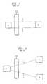
- FIG. 1illustrates a conventional symmetric NAT/firewall
- FIG. 2illustrates a conventional cone NAT/firewall
- FIG. 3illustrates a network communication bridge in accordance with the present invention
- FIG. 4is a schematic block diagram of the registrar of FIG. 3 ;
- FIG. 5is a schematic block diagram of the bridge proxy server of FIG. 3 ;
- FIG. 6is a flow chart describing an exemplary implementation of the registration process of FIG. 4 ;
- FIG. 7is a sample table from the exemplary registered user database of FIG. 4 ;
- FIG. 8is a flow chart describing an exemplary implementation of the proxy process of FIG. 5 ;
- FIG. 9illustrates a SIP implementation of a network communication bridge in accordance with the present invention.
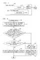
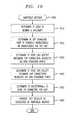
- FIG. 10is a flow chart describing an exemplary implementation of the AMIPUBLIC method of FIG. 9 ;
- FIG. 11is a flow chart describing an exemplary implementation of the MAKEMEPUBLIC method of FIG. 9 .
- the present inventionprovides an architecture for enabling communication between two systems that cannot ordinarily establish communication with each other, because a Network Address Translator or a firewall (or both) interferes.
- the present inventionprovides a solution to the NAT/firewall problem that is generic, lightweight and secure.
- the present inventioncan be implemented as a separate application using a proprietary protocol, or as an enhancement to the Session Initiation Protocol.
- the present inventionprovides an alternative to Virtual Private Networks and dial-in access, and supports general communication services including TCP and UDP data services as well as the more typical voice and video services supported by SIP.
- firewallsdo not allow communication initiation from outside of an enterprise network to a device within the enterprise network protected by the firewalls.
- NATscause additional problems for communication between an external device and a device connected to a protected network (or vice versa).
- systems outside the enterprise networkare unaware of the IP address of the internal device and hence cannot initiate communication with the internal device.
- the present inventionprovides a network communication bridge 300 , discussed further below in conjunction with FIG. 3 , that allows a user connected to a protected network to communicate with an external user.
- a network communication bridge 300includes a registrar 400 , discussed further below in conjunction with FIG. 4 , that accepts registration messages 330 from all authorized users who want to use the service.
- the registrar 400is positioned outside the protected network. The registrar 400 conducts a test to determine if the computing device associated with the user is publicly addressable (i.e., if the computing device can be reached from any computing device outside the enterprise).
- the registrar 400recommends that the computing devices maintain a persistent communication session with a bridge proxy server 500 , discussed further below in conjunction with FIG. 5 .
- the present inventionuse the services of the bridge proxy server 500 to relay packets from one computing device to the other computing device.
- NATsNetwork Address Translators
- NATssupply a stopgap solution to the IP address shortage problem, and they enhance security by hiding internal IP addresses from outsiders.
- a NATusually deployed on a network edge connecting two networks together, translates an internal private IP address of a system to a publicly routable IP address, before packets are forwarded outside the network, thereby enabling internal systems to communicate with outside systems.
- NATsare of two types, namely, traditional NATs and bi-directional NATs.
- Traditional NATsallow systems inside the network to successfully initiate and talk to systems outside the network.
- outside machinescannot initiate communication with systems within the network.
- a communication sessionis a TCP connection or a series of related UDP messages between the same source and destination ports.
- a UDP sessionmight be a simple request-response pair of messages, a Real Time Protocol (RTP) audio stream or other sessions between the same pair of ports as in Trivial File Transfer Protocol (TFTP).
- RTPReal Time Protocol
- NAPTsNetwork Address Port Translators
- a basic NATa block of external IP addresses is available for outside communication. An internal address is translated to an external address when the packet leaves the network.
- NAPTin addition to translating addresses, port numbers are also translated, thereby enabling the conservation of IP addresses (in the sense that more than one internal IP address could be translated to the same external IP address but with different external port numbers).
- port numberssince port numbers are not translated, different internal IP addresses must map to different external IP addresses for ongoing sessions.
- Bi-directional NATssupply either static or dynamic IP address translations. If a static translation from an internal IP address to an external IP address is known or a dynamic translation is long-lived, the external address can be used to initiate communication with the internal system unless such communication initiations are prevented by a firewall.
- ALGsApplication Level Gateways
- FTPfile transfer protocol
- NATsonly translate addresses in the IP header and port numbers in the transport header.
- ALGsare application specific; they scan an application's payload to do a corresponding address translation.
- firewallsare configured to drop incoming TCP connection request packets. Firewalls also drop most incoming UDP packets, in general allowing only UDP responses to an immediately prior UDP request on a well-known port number. In addition, some firewalls may perform packet filtering that blocks certain protocols or port numbers from transiting the firewall.
- FIG. 1illustrates a symmetric NAT/firewall 100 .
- symmetric NATs and firewallsallow response packets from the system to which the UDP packet was sent.
- the destination IP address and port number of the response packetmatch the source IP address and port number of the request packet.
- the source IP address and port number of the response packetmatch the destination IP address and port number of the request packet.
- the system within the networkcan communicate with the system outside the network, provided the inside system sends out the initial packet.
- FIG. 2illustrates a cone NAT/firewall 200 .
- Cone NATs/firewallsare different from symmetric NAT/firewalls 100 , in the sense that once a system within the enterprise sends a packet to a system outside the enterprise, any system from outside the enterprise can send response packets to this system within the enterprise. The destination IP address and port number of the response packet must match the source IP address and port number of the request packet.
- system Awhen system A, is behind a symmetric NAT/firewall 100 , system A can receive UDP packets only from system B outside the enterprise, provided system A has first sent out a UDP packet to system B.
- system Acan receive packets from system C, even though system A has only sent out a UDP packet to system B. Both B and C are outside the enterprise.
- firewallsare configured in such a way that they do not allow communication initiation from the outside to a system within the enterprise they are protecting.
- Deployment of NATshas its own drawbacks. Specifically, systems outside the enterprise are unaware of the IP address of the internal system and hence cannot initiate communication with the internal system. In certain cases, a provider will block incoming connection requests even though the internal device has a publicly routable IP address. The present invention helps such systems communicate with each other in a secure fashion.
- FIG. 3illustrates a network communication bridge 300 in accordance with the present invention that allows user A employing a computing device 310 within a network N 1 to communicate with user B employing a computing device 320 that is external to network N 1 .
- the computing device 310is connected to a first network N 1 (typically associated with a first enterprise) and the computing device 320 is connected to a second network N 2 (typically associated with a second enterprise).
- the networks N 1 and N 2may each typically provide one or more connections to a public network, such as the Internet.
- the connections to the public networkare typically protected by a network address translator or a firewall (or both), in the manner described above.
- the network communication bridge 300includes a registrar 400 , discussed further below in conjunction with FIG. 4 , that accepts registration messages 330 from all authorized users who want to use the service.
- the registrar 400then conducts a test (referred to as a check address message 340 ) to determine if the computing device associated with the user is publicly addressable (i.e., if the computing device can be reached from any computing device outside the enterprise). For those computing devices that are not publicly addressable, the registrar 400 recommends that the computing devices maintain a persistent communication session, such as the persistent communication session 350 associated with user A, with a bridge proxy server 500 , discussed further below in conjunction with FIG. 5 .
- the registrar 400optionally provides a list of proxy servers that they could contact.
- the list of proxy serverswould typically include publicly available bridge proxy servers 500 known to registrar 400 .
- the present inventionuse the services of the bridge proxy server 500 to relay packets from one computing device 310 to the other computing device 320 and vice versa.
- FIG. 4is a schematic block diagram of an exemplary registrar 400 .
- the registrar 400may be embodied as a general purpose computing system, such as the general purpose computing system shown in FIG. 4 .
- the registrar 400includes a processor 410 and related memory, such as a data storage device 420 , which may be distributed or local.
- the processor 410may be embodied as a single processor, or a number of local or distributed processors operating in parallel.
- the data storage device 420 and/or a read only memory (ROM)are operable to store one or more instructions, which the processor 410 is operable to retrieve, interpret and execute.
- the data storage device 420contains a registration process 600 that allows any user that wishes to use the network communication bridge 300 to register with the registrar 400 .
- the data storage device 420contains a registered user database 700 that records the contact information obtained by the registration process 600 .
- FIG. 5is a schematic block diagram of an exemplary bridge proxy server 500 .
- the bridge proxy server 500may be embodied as a general purpose computing system, similar to the general purpose computing system discussed above in conjunction with FIG. 4 .
- the data storage device 520contains a proxy process 800 that facilitates communications between two devices, where at least one device is not publicly addressable.
- the proxy process 800provides supporting services that include reversing the call initiator and call recipient during a communication initiation (when at least one party is publicly addressable) and relaying data packets (when neither party is publicly addressable).
- FIG. 6is a flow chart describing an exemplary implementation of the registration process 600 incorporating features of the present invention.
- the registration process 600is initiated by the registrar 400 when the registrar 400 receives the user identifier, IP address and port number from a computing device 310 , 320 associated with a user that desires to register with the network communication bridge 300 .
- user Awants to register with the registrar 400
- user Asends its user identifier, IP address and port number to the registrar 400 as part of the registration process.
- User Aalso starts listening on some port number, such as port x.
- a testis then performed during step 620 to compare the IP address and port number received from user A (computing device 310 ) with the IP address in the IP header and the port number in the transport header of the packet received from A. If it is determined during step 620 that these parameters match, then the registrar assumes that A is not behind a NAT. It is noted that multi-homed systems might send the packet on one interface while including the IP address of another interface thereby appearing to be behind a NAT. Multi-homed systems can send all their addresses in the message or a test by the bridge proxy server 500 to determine if the apparent NAT address is static would allow the bridge proxy server 500 to discover that the address is publicly routable.
- step 620Even if it is determined during step 620 that the parameters match, there still exists the possibility that user A (computing device 310 ) could be behind a firewall that disallows incoming connection requests.
- the registrar 400tries connecting to user A (computing device 310 ) on port x.
- a testis then performed during step 630 to determine if the connection initiation is successful. If it is determined during step 630 that the connection initiation was successful, then the registration process 600 assumes that user A is publicly addressable (i.e., any other system on the Internet can reach user A).
- the registrar 400registers the IP address and port number of user A (computing device 310 ) during step 660 in the registered user database 700 for user A.
- the registrar 400optionally sends a list of bridge proxy servers 500 to user A during step 650 and recommends that user A maintain a persistent session with one of these servers.
- the registrar 400communicates its results to user A via the communication session that user A initiated with it.
- the registrar 400registers the proxy's IP address and port number as A's address during step 670 in the registered user database 700 .
- the registrar 400would provide the appropriate contact information (either the IP address and port number of user A (computing device 310 ), if computing device 310 is publicly addressable, or the address of the appropriate bridge proxy server 500 , if computing device 310 is not publicly addressable). In this manner, if computing device 310 is not publicly addressable, any requests to communicate with user A are then routed to the bridge proxy server 500 which forwards them to A (using the persistent session maintained by user A). It is noted that this technique can be extended to test if a NAT-translated address is static or dynamic. Static NAT translations can be treated as public addresses while dynamic NAT translations require a persistent session with the bridge proxy server 500 .
- FIG. 7is a sample table from the registered user database 700 of FIG. 4 .
- the registered user database 700includes a plurality of records, such as records 705 - 720 , each associated with a different registered user. For each user identified in field 740 , the registered user database 700 indicates the IP address and port number to be utilized to communicate with the user in fields 750 and 760 , respectively. It is again noted that if the computing device 310 associated with the user is publicly addressable, the registered user database 700 would indicate the IP address and port number of user A (computing device 310 ), or if computing device 310 is not publicly addressable, then the registered user database 700 would indicate the address of the appropriate bridge proxy server 500 in fields 750 and 760 . In addition, the registered user database 700 optionally includes a flag in field 770 indicating whether the user is publicly addressable.
- FIG. 8is a flow chart describing an exemplary implementation of the proxy process 800 incorporating features of the present invention.
- the proxy process 800is initiated by the bridge proxy server 500 when the bridge proxy server 500 receives a communication during step 810 . Once a communication is received, the proxy process 800 performs a further test during step 820 to determine if at least one of the parties to the communication is publicly addressable.
- step 820If it is determined during step 820 that at least one of the parties to the communication is publicly addressable, then the message is forwarded to the indicated recipient during step 830 .
- user Bknows that it is publicly addressable.
- User Bstarts listening on port number y and sends a message to user A to contact user B on port number y.
- the request that user B sends to user Ais sent to the bridge proxy server 500 (as that is the address stored by the registrar 400 ) and received by the bridge proxy server 500 during step 810 .
- the bridge proxy server 500forwards the message to user A during step 830 and user A then initiates communication with B on port y. This is referred to as a “reversal.”
- both partieswould have established a persistent session with their respective bridge proxy server 500 as part of the registration process 600 .
- the initiator's requestis forwarded to the bridge proxy server 500 of the recipient and is received by the bridge proxy server 500 during step 810 .
- the bridge proxy server 500sees that the initiator is requesting a port, with which it can communicate with the recipient, and since the recipient is not publicly addressable, the bridge proxy server 500 opens a port for the initiator to use during step 840 .
- the bridge proxy server 500opens a port with which the recipient can initiate communication during step 850 .
- the bridge proxy server 500notifies the recipient, for example, using its persistent session with the recipient, that the initiator wants to communicate with the recipient on this newly opened port during step 860 .
- the recipientcan then initiate communication on its new port with the bridge proxy server 500 .
- the initiatoralso initiates communication with the port specified by the bridge proxy server 500 and all packets for the recipient are sent on the new data session the recipient has created with the bridge proxy server 500 .
- the bridge proxy server 500acts as a “relay service” for all communication between the initiator and the recipient.
- the bridge proxy server 500may tell user A to connect to port 1 on the proxy and may tell user B to connect to port 2 on the same or a different bridge proxy server 500 . Thereafter, the bridge proxy server 500 takes data received on port 1 , changes the return address to indicate the proxy server 500 , and sends the data to user B. Similarly, the bridge proxy server 500 takes data received on port 2 , changes the return address to indicate the proxy server 500 , and sends the data to user A.
- Case 1a—Bis Public and Wants to Communicate with A, Who is not Public
- Bknows that it is publicly addressable and hence anyone can connect to it.
- Bstarts listening on port number y and sends a message to A to contact it on port number y.
- the request that B sends Ais sent to the bridge proxy server 500 (as that is the address stored by the registrar 400 ) and the bridge proxy server 500 delivers this message to A.
- Athen initiates communication with B on port y.
- a and Bwould have maintained a persistent session with their respective bridge proxy server 500 .
- A's requestis forwarded to B's bridge proxy server 500 .
- the proxy 500sees that A is requesting a port, with which it can communicate with B, and since B is not publicly addressable, the proxy 500 opens a port for A to use. At the same time, the proxy 500 opens a port with which B can initiate communication.
- the bridge proxy server 500uses its persistent session with B to notify B that A wants to communicate with B on this newly opened port.
- Binitiates communication on its new port with the bridge proxy server 500 .
- Aalso initiates communication with the port specified by the proxy 500 and all packets for B are sent on the new data session B has created with the bridge proxy server 500 .
- the proxy 500acts as a relay service for all communication between A and B.
- system Acan maintain a persistent UDP session with the bridge proxy server 500 by sending keep-alive messages periodically to maintain its path through the firewall.
- system Awould then need to either initiate a separate data session with the bridge proxy server 500 or initiate a UDP session directly with the desired system publicly reachable for UDP traffic.
- the inside system Aalso initiates a UDP session with the bridge proxy server 500 and keeps this session alive.
- Other Internet systemscan then send requests to initiate communication directly to system A by using the same destination address and port number as those used by the bridge proxy server 500 in the persistent session.
- the internal system Acan create other ports for UDP sessions by sending an initial UDP request to a discard port on the bridge proxy server 500 .
- the bridge proxy server 500must assist in the communication initiation by communicating the translated address and port number to the internal system A or the other party in the communication.
- SIPcan support the network communication bridge 300 of the present invention with only a few changes. While SIP allows any two end-points to establish media sessions with each other, it also supports locating the end-points, exchanging the media information that enables the session to be established and closing down the session. Typically, SIP is used for setting up voice and video calls, conferencing calls, multicast sessions, and more recently instant messaging.
- a typical SIP systemconsists of user agents 910 , 920 (the caller is called the “user agent client” while the callee is called the “user agent server”), registration servers 900 , and SIP proxies 950 deployed all across the network.
- every usersends a registration message (“REGISTER”) to the registration server 900 , which stores the user's location.
- a SIP registration server 900also provides a location service.
- the registrar 400 discussed above in conjunction with FIGS. 3 and 4can be implemented as a SIP registration server 900 .
- SIP registration servers 900thus receive registrations from users and they make this information available to SIP proxy servers 950 .
- Registration servers 900typically require the user agent to be authenticated.
- the SIP proxy 950handles the routing of requests on behalf of a user agent, much as a proxy for HTTP handles web requests for client browsers.
- the registrar 900is part of a SIP proxy system 950 (i.e., they are located in the same physical system).
- the user's location informationis supplied to other users or proxies who query the location service of the registration server 900 to obtain a particular user's address. Once the registration is completed, the registration information must be periodically refreshed to let the registrar 900 know that the address for that user is still valid. The user is then ready to receive messages from other SIP users.
- SIPSession Description Protocol
- the SIP proxiesreceive requests from user agents and act on behalf of the user agent in forwarding or responding to the request.
- the proxy serverdoes not issue a request, it only responds to requests from user agents.
- SIP proxiescan either maintain state or be stateless. Proxies closer to the network edge usually maintain state, while those in the middle of the network can be stateless.
- SIP requestsThe various types of SIP requests, called methods, are described briefly herein. For a more detailed discussion of the SIP protocol and the various types of SIP requests, see, for example, M. Handley et al., “SIP: Session Initiation Protocol,” RFC 2543 (March 1999), incorporated by reference herein. These methods are considered verbs in the protocol as they request a specific action to be taken by the user agents, registrars or the proxy servers.
- the INVITE methodis used to invite other users to join a session. Responses to the INVITE method are always acknowledged with the ACK method.
- the message body of the INVITEcontains media information of the caller.
- the INVITE message bodytypically uses the SDP protocol to exchange media information for the session.
- the REGISTER methodis used when a user wants to notify the SIP system of his/her current location.
- the REGISTER methodalso has an Expires header and a user must periodically REGISTER with the registrar to maintain his/her status.
- Third party registrationis also supported wherein a third party sends the REGISTER method to the registrar on behalf of the actual user.
- the BYE methodis used to terminate an already established session.
- the BYE methodunlike the REGISTER method, cannot be sent by a third party. Only user agents participating in the session can send a BYE method.
- the ACK methodis used to acknowledge responses to INVITE requests.
- the ACK methodis not used as a response for the other methods.
- the CANCEL methodis used to terminate pending call attempts.
- the CANCEL methodcan be generated by any of the user agents or the proxy servers.
- the OPTIONS methodis used to query a user agent about its capabilities.
- the response to the OPTIONS methodlists the capabilities of that user agent.
- the firewallneeds to understand SIP and open up holes to allow traffic to pass in and out of the network.
- NATsare a challenge too, because once the request is forwarded outside the intranet, its originating private IP address would be converted by the NAT to a publicly routable one. Since addresses and port numbers are sent as part of SIP message bodies, the addresses and port numbers will have to be converted by the NAT as well.
- the SIP signaling channelcan either communicate using the TCP or UDP protocols.
- the data channels employed by the network communication bridge 300must conform to TCP or UDP. The determination of whether a system is publicly reachable is different for TCP and UDP implementations.
- AMIPUBLICAm I Public
- MAKEMEPUBLICMake Me Public! 1100
- the AMIPUBLIC method 1000 and the MAKEMEPUBLIC method 1100are executed by the registrar 900 and the SIP bridge proxy servers 950 , respectively, to implement aspects of the present invention.
- the AMIPUBLIC method 1000involves a test mechanism to determine if the user agent 910 , 920 is publicly addressable.
- the user agent 910 , 920can either register using the REGISTER method or make itself publicly addressable by establishing a persistent session with a SIP bridge proxy server 950 (stateful SIP proxies with extended capabilities).
- the MAKEMEPUBLIC methodis sent by the user agent 910 , 920 to the SIP bridge proxy server 950 as part of the persistent session establishment process.
- the SIP bridge proxy server 950relays packets to aid communication between systems that cannot ordinarily initiate communication with each other. It is important to note that the implementation of the present invention does not require the services of a bi-directional NAT or an ALG working in conjunction with the NAT. In addition, the present invention does not interfere with any of these servers if they are available.
- AMIPUBLICis a method to check if the user agent 910 , 920 is publicly addressable.
- a user agent 910 , 920sends this method to the registrar 900 .
- the registrar 900then executes the AMIPUBLIC method 1000 to conduct tests to check the user agent status, in a similar manner to the registration process 600 discussed above in conjunction with FIG. 6 .
- the AMIPUBLIC methodis optional and not a prerequisite to the REGISTER method. Those user agents 910 , 920 that know that they are publicly addressable could directly register with the registrars using the REGISTER method. Similarly, those user agents 910 , 920 that know that they are not publicly addressable could skip the AMIPUBLIC test method and proceed directly to the MAKEMEPUBLIC method. Clients can even use AMIPUBLIC to test their addressability status without later registering and using other SIP services.
- the Client (user agent) 910 , 920that wants to know its address status, sends an AMIPUBLIC method to the registrar 900 .
- the format of the AMIPUBLIC methodis the same as the REGISTER message from the SIP protocol, except that REGISTER is replaced by AMIPUBLIC.
- the Contact headerwill contain the client's domain name or IP address, and SIP port number, where the client can be reached. While the registrar 900 will check if this SIP signaling channel is publicly reachable, as discussed above in conjunction with FIG. 6 , it is also suggested that the user agent open TCP and UDP ports and listen for requests on those ports.
- the clientmust open a non-standard port, i.e., one that is not a well-known port number used by a standard protocol, as it would help determine if the firewall is dropping communication initiation packets to non-standard port numbers.
- Non-standard port numbersare opened for data transfer and we would like to verify if the client can successfully accept requests sent to a non-standard port number.
- the registrar 900determines if these data ports are publicly addressable or reachable via a NAT-translated IP address.
- the user agent 910 , 920can receive requests from any system on any port. If the user 910 , 920 is reachable via a NAT address, the user 910 , 920 may be publicly reachable via that address on a permanent (static NAT) or temporary basis (dynamic NAT). The user 910 , 920 can take additional actions to determine if the NAT is static or dynamic.
- the registrar 900notifies the client of the results of these tests and recommends a list of SIP bridge proxy servers 950 in case any of the above tests show that the user is not publicly addressable.
- a partial listmight be sent to remain within the size limit of a UDP packet.
- the proxies in the listcan be varied to provide load balancing.
- FIG. 10is a flow chart illustrating the AMIPUBLIC method 1000 . As shown in FIG. 10 , the AMIPUBLIC method 1000 conducts the following tests:
- Test 1involves no additional communication.
- Tests 2 through 5can be done sequentially or in parallel. Parallel testing can reduce the delay in receiving test results and the number of keep-alive messages sent by the requester to maintain a path through the firewall.
- the exemplary embodiment discussed hereinemploys a sequential implementation. It is noted that in parallel testing, attention must be paid to cases where redundant or unnecessary tests can be avoided. For example, Test 5 is unnecessary if Tests 2 through 4 succeed.
- the exemplary embodimentuses a technique proposed in the IETF to describe the endpoints of a TCP connection in SDP. See, D. Yon, “TCP Based Media Support in SDP” Internet Draft (October 2000).
- the present inventionextends the direction parameter proposed in TCP to specify the active and passive side of a session in UDP and extends SDP with a ‘data’ media type to support conventional TCP/UDP sessions.
- the user agent 910 , 920can also specify TCP and UDP ports on which it is waiting for connection requests. These port numbers are sent in an SDP message body in the AMIPUBLIC request.
- the registrar 900After receiving the AMIPUBLIC message, the registrar 900 tries to communicate with the user agent 910 , 920 on the IP address and port number specified in its Contact header. This is just to verify if the client 910 , 920 can receive outside communication requests on its SIP signaling channel.
- the user agent 910 , 920could use either TCP or UDP for the SIP signaling channel.
- the exemplary embodiment of the present inventionrequires that the user agent 910 , 920 send the AMIPUBLIC method over UDP.
- the user agent 910 , 920can still use TCP for its main SIP signaling channel by specifying TCP as the protocol in its Contact header. If the user agent 910 , 920 only wants to use TCP for both data and SIP signaling channel, then the user agent 910 , 920 can send the AMIPUBLIC method over TCP.
- the exemplary embodiment of the present inventionrequires the user agent 910 , 920 to specify a different UDP source port (in the UDP header) from its SIP signaling channel.
- the exemplary embodiment of the present inventionalso requires that the port specified in the UDP header listen for messages from the registrar and be able to respond successfully to SIP OPTIONS methods sent by the registrar. This is the only capability required of this UDP port.
- the followingis an exemplary format of an SDP message body of the AMIPUBLIC method. This implies that A (having an IP address 200.1.1.2) is listening for data connection requests on TCP port 5400 and requests on UDP port 5401 .
- the messagecan be retransmitted, e.g., every 30 seconds, to keep the path in the firewall/NAT open in case the user agent is behind a NAT/firewall.
- Test 1Is User Agent Behind a NAT or a NAPT?
- the registrar 900checks the Via header to see if there is a received tag appended along with the user agent's IP address.
- the received tagindicates that the request was received on an IP address that is different from the one on which it was sent.
- the rport tag proposed in the “NAT Friendly SIP” draft, referenced above,is used. If there is a received tag and a rport tag, then the user agent 910 , 920 could be behind a NAT and the registrar 900 makes a note of this possible NAT IP address and port number for the user agent 910 , 920 , for example, in the registered user database 700 .
- the registrar 900notes the address from which it received the request, and compares that address and port number with the contact method for the user agent 910 , 920 .
- a difference in just the IP addressesindicates a possible NAT address for the user agent 910 , 920 ; a difference in both the address and port indicates the possibility of a NAPT.
- the next task of the registrar 900is to check if the SIP signaling port is publicly reachable.
- the registrar 900sends the user agent 910 , 920 an OPTIONS method to the address specified in the Contact header of the AMIPUBLIC method. If the user agent 910 , 920 successfully receives the OPTIONS method, the user agent 910 , 920 sends back its list of capabilities to the registrar 900 . For clarity, the procedure to test this signaling channel is discussed separately for TCP and UDP.
- the registrar 900simply connects to the user agent 910 , 920 using TCP and sends the user agent 910 , 920 a SIP OPTIONS method. If the registrar 900 is unable to establish a TCP connection with the user agent 910 , 920 , then the SIP signaling channel is not publicly reachable for TCP. If tests fail and a possible NAT address has been noted, the registrar 900 tries to send the user agent 910 , 920 an OPTIONS method (but to the NAT's IP address and the SIP port umber of the user agent 910 , 920 ). If this is successful, the user agent 910 , 920 is behind a NAT.
- the user agent 910 , 920either has a static or dynamic address translation.
- the user agent 910 , 920then has the option of either conducting this AMIPUBLIC test over a period of time to ensure the address is static or playing it safe by establishing a persistent session with a SIP bridge proxy server 950 to ensure that the translation remains in place.
- the registrar 900concludes that the user agent 910 , 920 is not publicly addressable and recommends that the user agent 910 , 920 maintain a persistent connection with a SIP bridge proxy server 950 to receive SIP incoming messages.
- the registrar 900If the registrar 900 receives the AMIPUBLIC method from the user agent 910 , 920 , the registrar 900 responds with an OPTIONS method to the user agent 910 , 920 on its SIP signaling channel.
- the registrar 900must specify a different source UDP port from its SIP signaling port when sending the OPTIONS method over UDP. If the registrar 900 does not receive the user agent's response to its OPTIONS query and there is the possibility of a NAT, the registrar 900 again tries to send the OPTIONS method to the user agent 910 , 920 , but specifying the NAT's IP address and the user agent's SIP port.
- the registrar 900receives an answer from the user agent 910 , 920 , it notes that the user agent 910 , 920 is behind a NAT. In this case, the user agent 910 , 920 would again have the option of testing whether this is a static or dynamic translation. Since the user agent 910 , 920 refrains from making requests on the UDP signaling channel before testing the channel, a positive result to this test indicates that the IP address is public or the result of a simple NAT translation, not the result of a cone or symmetric path through the NAT/firewall.
- the registrar 900recommends a persistent session with a SIP bridge proxy server 950 .
- the NAT or firewallwill dynamically open short-term symmetric or cone paths in response to an outgoing UDP message.
- the ways to optimize UDP processing with the bridge proxy server 500differ depending on the type of opening made through the NAT or firewall.
- the client 910 , 920will not receive a response from the registrar 900 when a firewall drops the outgoing AMIPUBLIC UDP packet. If the client 910 , 920 can receive incoming UDP response packets, the client 910 , 920 will get a response from the registrar 900 containing the results of the AMIPUBLIC method. If the client 910 , 920 does not get any response from the registrar 900 after a reasonable period of time, the client 910 , 920 should timeout and use TCP as the underlying protocol for the AMIPUBLIC method. The user agent 910 , 920 can also then assume that it is not publicly addressable for UDP and cannot establish UDP data connections with any other system. Thus, it must not send UDP data ports for testing as part of the SDP message body.
- the registrar 900concludes that the SIP signaling channel of the user agent 910 , 920 is publicly addressable. If the registrar 900 did not receive a response or in the case of TCP, failed to connect to the user agent's SIP port, it is recommended that the user agent 910 , 920 establish a persistent session with a SIP bridge proxy server 950 . The details of establishing persistent sessions are discussed below in the section entitled “MAKEMEPUBLIC Method.”
- Test 3Can User Accept Incoming TCP Connection Requests on Non-Standard Ports?
- the registrarOnce the registrar has completed checking the reachability of the SIP signaling channel, it needs to test if the user agent's TCP data port (if specified) is publicly reachable. The registrar may have determined in the earlier test whether the user agent has a public address or an address behind a NAT. If it received all negative results in prior testing, it may be unsure of the address to test, so the registrar tests one address if the determination has been made or two addresses if the determination is still in question. The registrar tries to initiate a connection to the client on the TCP non-standard port specified by the client in the SDP message body of the AMIPUBLIC method. If the client successfully receives the connection initiation from the registrar, it echoes back whatever is sent.
- the clientwill be unable to receive and respond to the connection request sent by the registrar.
- the registrarcan thus determine if the client can be contacted or not for receiving data on TCP. Note that if contact is made through a NAT, the client will be publicly addressable for dynamic, as well as static NATs, if the client maintains its NAT translation by keeping a persistent session alive with a bridge proxy server 500 .
- Test 4Can User Accept Incoming UDP Connection Requests on Non-Standard Ports?
- the user agent 910 , 920is passively listening for connections on UDP port 5401 .
- the registrar 900may or may not know, based on previous tests, if the user agent 910 , 920 is behind a NAT.
- the registrar 900tests one address if the determination has been made or two addresses if the determination is still in question.
- the registrar 900tries to contact the client 910 , 920 on this passive port. If the client 910 , 920 receives this test message from the registrar 900 , the client 910 , 920 echoes back whatever the registrar 900 sent the client 910 , 920 on this port.
- the registrar 900concludes that the client 910 , 920 is addressable for UDP data as well.
- the client 910 , 920is publicly addressable if it is not behind a NAT, if the NAT translation is found on later testing to be static, or if it keeps its dynamic NAT translation alive by maintaining a persistent session with the SIP bridge proxy server 950 .
- the registrar 900If, however, the registrar 900 did not receive a reply to the message the registrar 900 sent the user agent 910 , 920 on the UDP data port, the registrar 900 knows that the user agent 910 , 920 is not publicly addressable. If any of the UDP tests fail, the registrar 900 then tries to ascertain the type of NAT or firewall treatment that is being given to dynamic UDP traffic. The results of this test (described in Test 5) help the SIP bridge proxy server 950 to serve the needs of UDP clients.
- Test 5Is NAT/Firewall Cone or Symmetric for UDP?
- the UDP source port from which the user agent 910 , 920 sent the AMIPUBLIC messagemust be listening for SIP OPTIONS methods. This port is used to figure out if the user agent 910 , 920 is behind a cone NAT/firewall. Even if a NAT is not present, the user agent 910 , 920 could be behind a firewall that drops incoming connection requests.
- Whether the user agent 910 , 920 can receive responses to UDP requests that the user agent 910 , 920 has sentshould be verified. Specifically, whether the NAT/firewall allows responses from any system or restricts responses to be from the system to which the user agent 910 , 920 has sent a UDP request should be verified.
- the registrar 900sends an OPTIONS message to the client 910 , 920 with the IP address and the UDP source port from which the user agent 910 , 920 sent the registrar 900 the AMIPUBLIC method.
- the registrar 900checks the Via header of the AMIPUBLIC message to check if the AMIPUBLIC request was routed by a SIP proxy. If the AMIPUBLIC request was routed by a SIP proxy, the registrar 900 sends an OPTIONS message to the UDP source port of the AMIPUBLIC method directly.
- the registrar 900sends the OPTIONS method to a proxy residing at a different IP address from the registrar 900 , to be forwarded to the user agent 910 , 920 . If the user agent 910 , 920 can receive and respond to this OPTIONS message on the UDP source port from which the AMIPUBLIC message was sent, it is concluded that the user agent 910 , 920 is behind a cone NAT/firewall.
- the registrar 900concludes that the user agent 910 , 920 is not behind a cone NAT/firewall after doing a reasonable number of retries for the user agent's response.
- the registrar 900then needs to check if the user agent 910 , 920 is behind a symmetric NAT/firewall. To this end, the registrar 900 either directly sends the user agent 910 , 920 the OPTIONS message or in case the proxy received the AMIPUBLIC, forwards and has the SIP bridge proxy server 950 send the OPTIONS message.
- the registrar 900then concludes that the user agent 910 , 920 is behind a symmetric NAT/firewall. If the user agent 910 , 920 does not respond to this message either, the user agent 910 , 920 cannot receive responses to UDP messages and the user agent 910 , 920 then has to try the AMIPUBLIC test with only TCP for both data and the main signaling channel.
- the registrar 900sends back a 200 OK message to the client 910 , 920 .
- the client 910 , 920can then register under its own IP address and SIP port number by sending the registrar 900 a REGISTER method. If on the other hand, any of the above tests failed, the registrar 900 sends back a 380 ‘Use alternate service’ error message to the client 910 , 920 .
- the message bodycontains the results of the tests conducted by the registrar 900 . If the user agent 910 , 920 has a public address, the following format is used:
- the following formatis used:
- the client's main SIP channelis publicly addressable, it implies that the client 910 , 920 can receive SIP requests on this port. Hence, it does not require a persistent connection with the SIP bridge proxy server 950 . If on the other hand, the SIP signaling channel of the client 910 , 920 is not publicly addressable, the client 910 , 920 will have to maintain a persistent session with the SIP bridge proxy server 950 . If the user agent 910 , 920 wants to use UDP for its signaling channel and is determined to be behind a cone NAT/firewall, then the user agent 910 , 920 needs to maintain a persistent session with the SIP bridge proxy server 950 and send periodic ‘keep alive’ messages.
- the user agent 910 , 920might have to establish data sessions with the SIP bridge proxy server 950 , when required, if the user agent 910 , 920 cannot receive data on non-standard ports. It is noted that while the client 910 , 920 should maintain a persistent session so that the user agent 910 , 920 does not miss any calls, it is entirely up to the user whether he/she wants the client to maintain a persistent session with the proxy server 950 .
- the firewallmay mistake the test communications from the registrar 900 to be attacks and shut out all future communications with the registrar 900 .
- the registrar 900should be added as a trusted host while configuring the firewall.
- Just one systemcan send out the AMIPUBLIC method and share the results with other hosts in the enterprise.
- the other systemscan then just send out MAKEMEPUBLIC methods (if required) and learn their external addresses (in case a NAT is deployed) from the MAKEMEPUBLIC response.
- the registrar 900will send back the 380 ‘Use alternate service’ error message to the client.
- the client 910 , 920will have to send one of the SIP bridge proxy servers 950 (recommended by the registrar) a MAKEMEPUBLIC method.
- FIG. 11is a flow chart describing an exemplary implementation of the MAKEMEPUBLIC method 1100 executed by a SIP bridge proxy server 950 .
- the MAKEMEPUBLIC method 1100initially authenticates the client 910 , 920 during step 1110 , for example, using the same authentication mechanism as the registration servers to authenticate clients issuing the REGISTER method.
- the client 910 , 920will send the SIP bridge proxy server 950 the test results sent to it by the registrar 900 .
- the clientcan directly send the SIP bridge proxy server 950 the test results (if the client 910 , 920 knows what the test results will be) without sending the AMIPUBLIC method 1000 .
- the user agent 910 , 920can also specify ‘Public Registration’ in the User-Agent header, to indicate that the user agent 910 , 920 wants to make itself public for receiving SIP services.
- the MAKEMEPUBLIC method 1100is also used when the user agent 910 , 920 wants to maintain a one-time session for sending or receiving data.
- the User-Agent headeris set to “Cone Data.”
- a testis performed during step 1120 to determine if the user 910 , 920 has specified a public registration or a one-time session. If it is determined during step 1120 that the user 910 , 920 has specified a public registration, then a persistent signaling session is established during step 1130 between the user agent 910 , 920 and the SIP bridge proxy server 950 . If the client 910 , 920 cannot receive SIP requests, then the client 910 , 920 needs to maintain this session persistently with the SIP bridge proxy server 950 . If, however, it is determined during step 1120 that the user 910 , 920 has specified a one-time session, then a one-time session for sending or receiving data is established during step 1150 .
- the SIP bridge proxy server 950records the contact information about the user agent 910 , 920 in a table during step 1160 , such as a unique username, ⁇ IP address, Port number>, socket for persistent sessions, whether a persistent session is required, whether TCP data connection support is required, and whether UDP data connection support is required for a cone or symmetric NAT/firewall.
- An exemplary table entrywould look as follows:
- the SIP bridge proxy server 950sends back a 200 OK message to the user agent 910 , 920 during step 1170 .
- the SIP bridge proxy server 950sends back to the client the SIP bridge proxy server 950 its external IP address and port number (the NAT translated address and port of the user agent).
- the proxy server 950registers the client with the registrar 900 using the IP address and SIP port of the SIP bridge proxy server 950 via the third party registration technique specified in SIP's REGISTER method.
- the SIP bridge proxy server 950registers the user agent 910 , 920 using the user agent's publicly routable address.
- the registrar 900maintains a table 700 where a user's location is mapped to the IP address and port number on the proxy server.
- the location service 900sends the address of the proxy server (whenever a persistent session has been established to make the client public for some SIP services).
- the SIP bridge proxy server 950is responsible for refreshing the client's registration with the Registrar 900 at appropriate intervals and for removing the registration if connectivity with the client is lost.
- both A and Bcan receive SIP requests as they can be either publicly reachable on their SIP ports or will be maintaining persistent connections to a SIP bridge proxy server 950 . There are three possible cases.
- the invite messageis sent to B either directly (if B's SIP signaling channel is publicly reachable) or through the appropriate SIP bridge proxy server 950 (if B is using some services of the SIP bridge proxy server 950 ). If user B wants to talk to user A, user B responds to A's invite message by sending user A an OK message and then initiating a connection to user A on the port number user A specified in the INVITE message.
- user Awill send a SIP INVITE message to user B, but since user A cannot receive connection initiations from outside the enterprise machines, user A specifies the direction as active in the following SDP message body. Since the direction is active, the port number can be set to 9 by user A and can be ignored by the recipient.
- An example of a SDP message for this caseis:
- user BWhen user B (having IP address 199.10.10.2) gets this INVITE message and realizes that user A is not publicly reachable, but user B itself can receive connection initiations, user B opens a port (in this case 24000) and waits for user A to initiate a connection to user B on that port.
- User Bspecifies this port number and its own IP address in the SDP message body user B sends along with the 200 OK method back to user A, as follows:
- the services of the SIP bridge proxy server 950are required for establishing the data connection.
- user Asends an INVITE message to user B with a special port number and direction set to active in the SDP message (an indication that a port number has to be arranged by user B for the communication)
- the INVITE messagegets routed to the appropriate SIP bridge proxy server 950 for user B.
- the proxy 950knows that user B is not publicly addressable, and hence will open a port for user B to connect to the proxy 950 .
- the proxy 950rewrites the SDP message body of A's INVITE using this port number and will route A's INVITE to B's SIP signaling channel.
- the SIP bridge proxy server 950opens a port for A to connect to and forwards B's 200 OK message to user A, adding its own IP address and the port number the proxy 950 has set up for A in the SDP message body.
- User Athen sends back an ACK message for the 200 OK that user A received from user B.
- User Bconnects to the port number specified by the SIP bridge proxy server 950 and user A does the same. All messages sent by user A will now go to this proxy and these are relayed by the proxy to user B through the data connection user B has started with the proxy.
- UDP sessionsIn the case of UDP sessions, a user system could be publicly addressable, be behind a symmetric NAT/firewall or be behind a cone NAT/firewall. Now, consider the cases when user A wants to talk to user B. UDP data transfer itself has two cases. One occurs when symmetric initiation of communication is possible. This case is similar to TCP, because clients specify the direction as active or passive in the SDP message. In the second case, a system must have a port ready when the system sends the INVITE method.
- a symmetric UDP communication initiationsuch as a symmetric Real Time Protocol (RTP), described in D. Hoffman et al., “RTP Payload Format for MPEG1/MPEG2 Video,” RFC 2250 (January, 1998).
- RTPReal Time Protocol
- the technique of specifying direction as either active or passiveis possible.
- the ports that listen for dataalso send data (unlike the current implementations of RTP).
- Other UDP applicationscan be made symmetric by establishing an initial message (which can be discarded by the recipient) to be sent by whichever party is active.
- the services of the SIP bridge proxy server 950 for relaying messagesare not utilized except when both A and B are behind symmetric NATs/firewalls.
- Case 1A is Publicly Reachable; B is Publicly Reachable or Behind a NAT/Firewall
- Ais publicly reachable. In this case, B's status does not matter.
- user Alistens on a port and sends this port and its publicly reachable address as part of the SDP message body. User A specifies its direction as passive. User B then connects to the port specified by user A and they carry out their communication.
- Case 2A is Behind a Cone NAT/Firewall; B is Public or Behind a NAT/Firewall
- user Ais behind a cone NAT/firewall.
- User Acan be publicly addressed provided user A has sent out a UDP packet thereby creating a path in the firewall to receive data.
- user Astarts listening on a socket and sends out a MAKEMEPUBLIC method 1100 to the SIP bridge proxy server 950 from this source port.
- user Aspecifies ‘Cone Data’ and puts its SIP signaling port in the Contact header.
- the SIP bridge proxy server 950realizes that user A just wants to know its external IP address and port as user A wants to establish a data channel with another system.
- the SIP bridge proxy server 950sends back to user A its external IP address and the port number user A will be listening for requests.
- a pathis opened in the firewall for packets from user B to reach user A.
- User Athen sends out an INVITE message to user B, specifying in the SDP message body, the IP address and port number that the SIP bridge proxy server 950 sent in response to user A's MAKEMEPUBLIC method.
- User Bthen directly connects to user A.
- Case 3A is Behind a Symmetric NAT/Firewall; B is Public or Behind a NAT/Firewall
- user Ais behind a symmetric NAT/firewall.
- User Asends out an INVITE to user B, but specifies in its SDP message body that it wishes to be the active side of the connection.
- user Bis publicly reachable, user B listens on a port and sends this port to user A. User A initiates communication with this port.
- user Bis behind a cone NAT/firewall, user B listens on a port and sends the appropriate SIP bridge proxy server 950 a MAKEMEPUBLIC message 1100 with User-Agent set to ‘Cone Data’ from this port.
- User Bgets back its external IP address and port from the SIP bridge proxy server 950 .
- the SIP bridge proxy server 950listens on two ports (one to which user A connects and the other to which user B connects) and rewrites the SDP messages appropriately. Before the SIP bridge proxy begins relaying data, A and B activate their paths for receiving data from the proxy by sending a message to the proxy on the port provided. This opens a hole through the symmetric firewall for communication from the proxy. The SIP bridge proxy server 950 then relays messages between users A and B.
- the present inventionsupports existing UDP data session transfers.
- a system that wants to communicate with another systemmust specify its address and port in the INVITE message itself.
- classic RTPspecifies the port number for receiving data in the SDP message. It also implicitly specifies the next sequential port number for its control protocol RTCP.
- RTCPthe port for RTCP should be specified explicitly in the SDP message. Otherwise, a NAPT may allocate non-consecutive ports to RTP and RTCP and this will not be communicated appropriately.
- a new User-Agent header optionis proposed called ‘Symmetric Data’ for the MAKEMEPUBLIC methods.
- the SIP bridge proxy server 950realizes that the user agent is requesting a port for establishing a UDP data session.
- the SIP bridge proxy server 950then opens two ports and sends these ports and the IP address of the SIP bridge proxy server 950 back to the user agent (one for A to receive data from and the other for B to send data to).
- User agent Athen activates its port for receiving data from the proxy by sending a message to the proxy at that port number. This opens a hole through the symmetric firewall for communication from the proxy 950 to A.
- Case 1A is Publicly Reachable; B is Publicly Reachable or Behind a NAT/Firewall
- User Abeing public, can send a port number to user B in its SDP message body. If user B is also public, user B can also send a port number back to user A. If user B is behind a cone NAT/firewall, user B can send out a MAKEMEPUBLIC method with the User-Agent header set to ‘Cone Data’ to the appropriate SIP bridge proxy server 950 . As discussed above, this creates a path in the NAT/firewall and user A can send data to user B on this port. If, however, user B is behind a symmetric NAT/firewall, user B needs to establish a communication channel with its SIP bridge proxy server 950 .
- User Bsends its SIP bridge proxy server 950 a MAKEMEPUBLIC message with the User-Agent header set to ‘Symmetric Data.’
- the SIP bridge proxy server 950then creates two ports, one for user A to use to send data to user B and one for user B to use to receive user A's messages.
- a possible port usage optimizationwould use one port for relaying UDP traffic between users A and B at the expense of reading the packet to determine its destination.
- User Bsends the port number created by the SIP bridge proxy server 950 for user A in its 200 OK message and connects to the port on the SIP bridge proxy server 950 meant for user B.
- User Balso begins communication on the port number set by user A (in user A's INVITE message) to send user A data.
- User Anow initiates communication with the port on the SIP bridge proxy server 950 for sending data to user B.
- user Bcan send data directly to user A, while user A sends data meant for user B to user B's SIP bridge proxy server 950 which is then relayed to user B.
- Case 2A is Behind a Cone NAT/Firewall; B is Public or Behind a NAT/Firewall
- user Asends out a MAKEMEPUBLIC method with the User-Agent set to ‘Cone Data’ to the SIP bridge proxy server 950 .
- the remaining communicationis along the same lines as Case 1, discussed above. If user B is public or is behind a cone NAT/firewall, users A and B can talk directly to each other. If user B is behind a symmetric NAT/firewall, user B requires the services of the SIP bridge proxy server 950 as described in Case 1.
- Case 3A is Behind a Symmetric NAT/Firewall; B is Public or Behind a NAT/Firewall
- user AIf user A is behind a symmetric NAT/firewall, it sends out a MAKEMEPUBLIC method with the User-Agent set to ‘Symmetric Data’ to the SIP bridge proxy server 950 .
- the SIP bridge proxy server 950opens two ports, one with which user A initiates communication and the other with which user B initiates communication. As described in the previous cases, if user B is public, user A can send data directly to user B, while user B sends data meant for user A to the SIP bridge proxy server 950 . If user B is behind a cone Nat/firewall, user B creates a path in the NAT/firewall by sending out the MAKEMEPUBLIC method with the User-Agent set to ‘Cone Data’ to its SIP bridge proxy server 950 .
- both users A and Bwill have to send MAKEMEPUBLIC methods to their respective SIP bridge proxy servers 950 with the User-Agent set to ‘Symmetric Data’.
- both the SIP bridge proxy servers 950will be required to set ports for communication with the other end, user A would send data to user B's SIP bridge proxy server 950 and user B would send data for user A to user A's SIP bridge proxy server 950 .
- the network communication bridge 300 of the present inventionallows connectivity between any two systems.
- the network communication bridge 300can be put to use in numerous ways.
- An independent implementation of the architecture of the present inventionwould be a lightweight and secure alternative to VPNs and dial-in servers (solutions that are currently used to connect to the enterprise).
- Any other system that needs deployment of bi-directional NATs in conjunction with ALGs and special firewall softwarecan use the present invention for connectivity.
- the present inventiondoes not require the deployment of ALGs for every application used by the systems behind a NAT. Since SIP is gaining in popularity, a SIP implementation of the present invention would enable users behind NATs and firewalls to communicate effectively with other systems for both voice and text data.
- the methods and apparatus discussed hereinmay be distributed as an article of manufacture that itself comprises a computer readable medium having computer readable code means embodied thereon.
- the computer readable program code meansis operable, in conjunction with a computer system, to carry out all or some of the steps to perform the methods or create the apparatuses discussed herein.
- the computer readable mediummay be a recordable medium (e.g., floppy disks, hard drives, compact disks, or memory cards) or may be a transmission medium (e.g., a network comprising fiber-optics, the world-wide web, cables, or a wireless channel using time-division multiple access, code-division multiple access, or other radio-frequency channel). Any medium known or developed that can store information suitable for use with a computer system may be used.
- the computer-readable code meansis any mechanism for allowing a computer to read instructions and data, such as magnetic variations on a magnetic media or height variations on the surface of a compact disk.
- the computer systems and servers described hereineach contain a memory that will configure the associated processors to implement the methods, steps, and functions disclosed herein.
- the memoriescould be distributed or local and the processors could be distributed or singular.
- the memoriescould be implemented as an electrical, magnetic or optical memory, or any combination of these or other types of storage devices.
- the term “memory”should be construed broadly enough to encompass any information able to be read from or written to an address in the addressable space accessed by an associated processor. With this definition, information on a network is still within a memory because the associated processor can retrieve the information from the network.
Landscapes
- Engineering & Computer Science (AREA)
- Computer Networks & Wireless Communication (AREA)
- Signal Processing (AREA)
- Multimedia (AREA)
- Business, Economics & Management (AREA)
- General Business, Economics & Management (AREA)
- Computer Hardware Design (AREA)
- Computer Security & Cryptography (AREA)
- Computing Systems (AREA)
- General Engineering & Computer Science (AREA)
- Data Exchanges In Wide-Area Networks (AREA)
Abstract
Description
- 1. Check if the user is behind a NAT/NAPT (Step1010);
- 2. Check if the SIP signaling port is publicly addressable or addressable via the NAT (Step1020);
- 3. Check if the user can accept incoming TCP connection requests on non-standard ports (Step1030);
- 4. Check if the user can accept incoming UDP connection requests on non-standard ports (Step1040);
- 5. Check if the NAT/firewall is cone or symmetric for UDP (Step1050); and
- 6. Provide test results to requester of AMIPUBLIC method1000 (Step1060).
- c=IN IP4 200.1.1.2/5000
- m=data 5400 TCP 0
- a=direction:passive
- m=data 5401 UDP 0
- a=direction:passive
- SIP main: Yes/No/Symmetric/Cone
- TCP data: Yes/No
- UDP data: Yes/No/Symmetric/Cone
It is noted that the Cone or Symmetric type applies only for the UDP protocol. In the case of the TCP protocol, the options would be either yes or no.
- NAT: <address, port discovered>
- SIP main: Yes/No/Symmetric/Cone
- TCP data: Yes/No
- UDP data: Yes/No/Symmetric/Cone
Theregistrar 900 also sends as part of the message body a list of SIPbridge proxy servers 950 with whom theclient
- username@bridgeproxy.com, <200.10.10.10,5060>, < >, False, True, cone
This implies that the user (username@bridgeproxy.com) can be contacted at 200.10.10.10:5060, the socket is null, no persistent connection is required, and the user would need help from the SIPbridge proxy server 950 to establish TCP and UDP data sessions. As an optimization, the SIPbridge proxy server 950 can establish a connection with the user as needed via the public SIP signaling channel and does not maintain a persistent session with the user. Depending on whether theuser agent bridge proxy server 950 would have the client's own IP address and SIP port number or the address and port of the persistent connection maintained with it in its table. It is noted that if theuser agent bridge proxy server 950 in its table. The SIPbridge proxy server 950 uses information from this table for routing SIP messages to theuser
- username@bridgeproxy.com, <200.10.10.10,5060>, < >, False, True, cone
- c=IN IP4 200.1.1.2/2047
- m=data 54000 TCP 0
- a=direction:passive
where “200.1.1.2” indicates A's IP address and “2047” is the source port from which A is sending that message. “54000” is the port on which A wants B to connect to A using TCP.
- c=IN IP4 200.1.1.2/2047
- m=data 9 TCP 0
- a=direction:active
- c=IN IP4 199.10.10.2/2000
- m=data 24000 TCP 0
- a=direction:passive
Claims (18)
Priority Applications (1)
| Application Number | Priority Date | Filing Date | Title |
|---|---|---|---|
| US10/208,474US9497168B2 (en) | 2002-07-30 | 2002-07-30 | Method and apparatus for supporting communications between a computing device within a network and an external computing device |
Applications Claiming Priority (1)
| Application Number | Priority Date | Filing Date | Title |
|---|---|---|---|
| US10/208,474US9497168B2 (en) | 2002-07-30 | 2002-07-30 | Method and apparatus for supporting communications between a computing device within a network and an external computing device |
Publications (2)
| Publication Number | Publication Date |
|---|---|
| US20040024879A1 US20040024879A1 (en) | 2004-02-05 |
| US9497168B2true US9497168B2 (en) | 2016-11-15 |
Family
ID=31186829
Family Applications (1)
| Application Number | Title | Priority Date | Filing Date |
|---|---|---|---|
| US10/208,474Active2026-11-06US9497168B2 (en) | 2002-07-30 | 2002-07-30 | Method and apparatus for supporting communications between a computing device within a network and an external computing device |
Country Status (1)
| Country | Link |
|---|---|
| US (1) | US9497168B2 (en) |
Cited By (3)
| Publication number | Priority date | Publication date | Assignee | Title |
|---|---|---|---|---|
| US20160269489A1 (en)* | 2013-09-30 | 2016-09-15 | Orange | Technique for Remote Administration of a Device Belonging to a Private Network |
| US11063908B2 (en)* | 2018-11-05 | 2021-07-13 | Sumitomo Electric Industries, Ltd. | On-vehicle communication device, communication control method, and communication control program |
| US20240007328A1 (en)* | 2022-04-26 | 2024-01-04 | Deutsche Telekom Ag | Operating a broadband access network of a telecommunications network with a customer premises equipment |
Families Citing this family (260)
| Publication number | Priority date | Publication date | Assignee | Title |
|---|---|---|---|---|
| US8458754B2 (en) | 2001-01-22 | 2013-06-04 | Sony Computer Entertainment Inc. | Method and system for providing instant start multimedia content |
| US20030009561A1 (en)* | 2001-06-14 | 2003-01-09 | Sollee Patrick N. | Providing telephony services to terminals behind a firewall and /or network address translator |
| US7711847B2 (en) | 2002-04-26 | 2010-05-04 | Sony Computer Entertainment America Inc. | Managing users in a multi-user network game environment |
| US20030217135A1 (en) | 2002-05-17 | 2003-11-20 | Masayuki Chatani | Dynamic player management |
| US8560707B2 (en) | 2007-10-05 | 2013-10-15 | Sony Computer Entertainment America Llc | Seamless host migration based on NAT type |
| US8131802B2 (en) | 2007-10-05 | 2012-03-06 | Sony Computer Entertainment America Llc | Systems and methods for seamless host migration |
| US8224985B2 (en)* | 2005-10-04 | 2012-07-17 | Sony Computer Entertainment Inc. | Peer-to-peer communication traversing symmetric network address translators |
| US8060626B2 (en) | 2008-09-22 | 2011-11-15 | Sony Computer Entertainment America Llc. | Method for host selection based on discovered NAT type |
| US8166533B2 (en)* | 2002-08-17 | 2012-04-24 | Rockstar Bidco Lp | Method for providing media communication across firewalls |
| JP3445986B1 (en)* | 2002-09-27 | 2003-09-16 | 松下電器産業株式会社 | Servers, devices and communication systems connected to the Internet |
| US20040064584A1 (en)* | 2002-09-27 | 2004-04-01 | Julian Mitchell | Apparatus and methods of assisting in NAT traversal |
| US7110763B2 (en)* | 2002-12-12 | 2006-09-19 | Alcatel | Graphical proxy for less capable terminals |
| US7403995B2 (en)* | 2003-01-08 | 2008-07-22 | Outhink, Inc. | Symmetrical bi-directional communication |
| US7899932B2 (en)* | 2003-01-15 | 2011-03-01 | Panasonic Corporation | Relayed network address translator (NAT) traversal |
| WO2004063843A2 (en)* | 2003-01-15 | 2004-07-29 | Matsushita Electric Industrial Co., Ltd. | PEER-TO-PEER (P2P) CONNECTION DESPITE NETWORK ADDRESS TRANSLATOR (NATs) AT BOTH ENDS |
| FR2853187B1 (en)* | 2003-03-28 | 2006-01-13 | At & T Corp | SYSTEM FOR ALL NETWORK APPLICATION TO OPERATE TRANSPARENTLY THROUGH A NETWORK ADDRESS TRANSLATION DEVICE |
| US20040249973A1 (en)* | 2003-03-31 | 2004-12-09 | Alkhatib Hasan S. | Group agent |
| US7543061B2 (en)* | 2003-06-26 | 2009-06-02 | Microsoft Corporation | Method and system for distributing load by redirecting traffic |
| US7363378B2 (en)* | 2003-07-01 | 2008-04-22 | Microsoft Corporation | Transport system for instant messaging |
| US20050050211A1 (en)* | 2003-08-29 | 2005-03-03 | Kaul Bharat B. | Method and apparatus to manage network addresses |
| US7760744B1 (en)* | 2003-11-20 | 2010-07-20 | Juniper Networks, Inc. | Media path optimization for multimedia over internet protocol |
| US7694127B2 (en)* | 2003-12-11 | 2010-04-06 | Tandberg Telecom As | Communication systems for traversing firewalls and network address translation (NAT) installations |
| US20050207433A1 (en)* | 2004-01-09 | 2005-09-22 | Camelot Technology Associates Ltd. | Video communication systems and methods |
| CA2457368C (en)* | 2004-02-11 | 2013-01-08 | Solutioninc Limited | A server, system and method for providing access to a public network through an internal network of a multi-system operator |
| TW200605574A (en)* | 2004-02-17 | 2006-02-01 | Ginganet Corp | Address resolution apparatus, address resolution method and telecommunication system thereof |
| US7426569B2 (en)* | 2004-02-25 | 2008-09-16 | Research In Motion Limited | System and method for maintaining a network connection |
| JP2005242543A (en)* | 2004-02-25 | 2005-09-08 | Sony Corp | Information processing method, information processor, and computer program |
| US8085741B2 (en)* | 2004-03-10 | 2011-12-27 | Core Wireless Licensing S.A.R.L. | System and method for pushing content to a terminal utilizing a network-initiated data service technique |
| US8989737B2 (en)* | 2004-03-10 | 2015-03-24 | Nokia Corporation | System and method for establishing a session initiation protocol communication session with a mobile terminal |
| US7599374B2 (en)* | 2004-03-10 | 2009-10-06 | Nokia Corporation | System and method for establishing an Internet Protocol connection with a terminating network node |
| US8050272B2 (en) | 2004-06-29 | 2011-11-01 | Damaka, Inc. | System and method for concurrent sessions in a peer-to-peer hybrid communications network |
| US8437307B2 (en) | 2007-09-03 | 2013-05-07 | Damaka, Inc. | Device and method for maintaining a communication session during a network transition |
| US7933260B2 (en) | 2004-06-29 | 2011-04-26 | Damaka, Inc. | System and method for routing and communicating in a heterogeneous network environment |
| US8009586B2 (en) | 2004-06-29 | 2011-08-30 | Damaka, Inc. | System and method for data transfer in a peer-to peer hybrid communication network |
| US7570636B2 (en) | 2004-06-29 | 2009-08-04 | Damaka, Inc. | System and method for traversing a NAT device for peer-to-peer hybrid communications |
| US7962623B2 (en)* | 2004-06-30 | 2011-06-14 | Microsoft Corporation | Sustaining session connections |
| US20060056379A1 (en)* | 2004-09-14 | 2006-03-16 | Motorola, Inc. | System and method for network-assisted connection in a wireless environment |
| US7594259B1 (en)* | 2004-09-15 | 2009-09-22 | Nortel Networks Limited | Method and system for enabling firewall traversal |
| US7805517B2 (en)* | 2004-09-15 | 2010-09-28 | Cisco Technology, Inc. | System and method for load balancing a communications network |
| US8200827B1 (en)* | 2004-10-25 | 2012-06-12 | Juniper Networks, Inc. | Routing VoIP calls through multiple security zones |
| CN101053218B (en)* | 2004-11-08 | 2011-07-20 | 松下电器产业株式会社 | Communication terminal and communication method |
| US7702094B2 (en)* | 2004-11-30 | 2010-04-20 | Aspect Software, Inc. | Method of storing information within an ACD |
| US7823196B1 (en) | 2005-02-03 | 2010-10-26 | Sonicwall, Inc. | Method and an apparatus to perform dynamic secure re-routing of data flows for public services |
| US7558267B2 (en)* | 2005-02-11 | 2009-07-07 | Microsoft Corporation | Method and system for placing restrictions on sessions |
| FI118316B (en)* | 2005-02-14 | 2007-09-28 | Teliasonera Ab | Communication channel between at least two private networks |
| EP1694034B1 (en)* | 2005-02-16 | 2014-05-21 | Alcatel Lucent | Method to establish a peer-to-peer connection between two user agents located behind symmetric NATs |
| CA2598019C (en)* | 2005-02-16 | 2013-04-30 | Qualcomm Incorporated | Low duty cycle half-duplex mode operation with communication device |
| KR100643292B1 (en)* | 2005-04-29 | 2006-11-10 | 삼성전자주식회사 | Session initiation protocol terminal user address information management method and server therefor |
| US7594020B2 (en)* | 2005-05-31 | 2009-09-22 | Microsoft Corporation | Re-establishing a connection for an application layer via a service layer |
| JP2006343943A (en)* | 2005-06-08 | 2006-12-21 | Murata Mach Ltd | File server device and communication management server device |
| KR100785296B1 (en)* | 2005-07-21 | 2007-12-12 | 삼성전자주식회사 | Apparatus and method for data transmission control in VoIP gateway |
| US9053461B2 (en) | 2005-10-07 | 2015-06-09 | Yahoo! Inc. | Instant messaging interoperability between disparate service providers |
| US7730192B2 (en)* | 2006-03-20 | 2010-06-01 | Microsoft Corporation | Managing parallel requests in a communications environment supporting serial and parallel request handlers |
| US7907599B2 (en)* | 2006-04-10 | 2011-03-15 | Network Equipment Technologies, Inc. | Determination of SIP transport to reduce call setup delays |
| US20070271106A1 (en)* | 2006-05-19 | 2007-11-22 | Lee David H | System and method for secure internet channeling agent |
| US8700105B2 (en) | 2006-06-22 | 2014-04-15 | Qualcomm Incorporated | Low duty cycle device protocol |
| US8018884B2 (en) | 2006-06-21 | 2011-09-13 | Qualcomm Incorporated | Low duty cycle network controller |
| US20080032728A1 (en)* | 2006-08-03 | 2008-02-07 | Bina Patel | Systems, methods and devices for communicating among multiple users |
| US8559947B2 (en)* | 2006-09-13 | 2013-10-15 | Mformation Software Technologies Llc | System and method to enable subscriber self-activation of wireless data terminals |
| US8576851B2 (en)* | 2006-09-22 | 2013-11-05 | Microsoft Corporation | Integrating data with conversations |
| JP2008085470A (en)* | 2006-09-26 | 2008-04-10 | Fujitsu Ltd | IP application service providing system |
| US8509788B2 (en)* | 2007-03-08 | 2013-08-13 | Motorola Mobility Llc | Dynamic sharing of wireless resources among different communication networks |
| US9462060B2 (en)* | 2007-04-23 | 2016-10-04 | Alcatel Lucent | System and method for sending notification message to a mobile station using session initiation protocol (SIP) |
| US7995478B2 (en)* | 2007-05-30 | 2011-08-09 | Sony Computer Entertainment Inc. | Network communication with path MTU size discovery |
| EP2165505B1 (en)* | 2007-07-10 | 2016-06-01 | Telefonaktiebolaget LM Ericsson (publ) | A method of discovering operator-provided network-services using ims. |
| US7933273B2 (en)* | 2007-07-27 | 2011-04-26 | Sony Computer Entertainment Inc. | Cooperative NAT behavior discovery |
| US9483405B2 (en)* | 2007-09-20 | 2016-11-01 | Sony Interactive Entertainment Inc. | Simplified run-time program translation for emulating complex processor pipelines |
| WO2009043016A2 (en) | 2007-09-28 | 2009-04-02 | Damaka, Inc. | System and method for transitioning a communication session between networks that are not commonly controlled |
| US8380859B2 (en) | 2007-11-28 | 2013-02-19 | Damaka, Inc. | System and method for endpoint handoff in a hybrid peer-to-peer networking environment |
| US7856501B2 (en) | 2007-12-04 | 2010-12-21 | Sony Computer Entertainment Inc. | Network traffic prioritization |
| FI120479B (en)* | 2007-12-05 | 2009-10-30 | Telcont Oy | Procedure and timing for establishing connection to an apparatus |
| US7856506B2 (en)* | 2008-03-05 | 2010-12-21 | Sony Computer Entertainment Inc. | Traversal of symmetric network address translator for multiple simultaneous connections |
| US9456054B2 (en) | 2008-05-16 | 2016-09-27 | Palo Alto Research Center Incorporated | Controlling the spread of interests and content in a content centric network |
| US9185654B2 (en)* | 2008-07-16 | 2015-11-10 | Qualcomm Incorporated | Network server having an information and scheduling controller to support one or more low duty cycle wireless devices |
| US20100040046A1 (en)* | 2008-08-14 | 2010-02-18 | Mediatek Inc. | Voip data processing method |
| US20100077057A1 (en)* | 2008-09-23 | 2010-03-25 | Telefonaktiebolaget Lm Ericsson (Publ) | File Transfer in Conference Services |
| US9160794B2 (en)* | 2008-12-04 | 2015-10-13 | Microsoft Technology Licensing, Llc | Network address translators (NAT) type detection techniques |
| US8090850B2 (en)* | 2008-12-12 | 2012-01-03 | Tekelec | Methods, systems, and computer readable media for regulating network address translator (NAT) and firewall pinhole preservation traffic in a session initiation protocol (SIP) network |
| US20100293072A1 (en)* | 2009-05-13 | 2010-11-18 | David Murrant | Preserving the Integrity of Segments of Audio Streams |
| US8923293B2 (en) | 2009-10-21 | 2014-12-30 | Palo Alto Research Center Incorporated | Adaptive multi-interface use for content networking |
| US8126987B2 (en) | 2009-11-16 | 2012-02-28 | Sony Computer Entertainment Inc. | Mediation of content-related services |
| US9219637B2 (en)* | 2010-01-30 | 2015-12-22 | Oleg Boulanov | Facilitating rapid establishment of human/machine communication links with private SIP-based IP networks using pre-distributed static network address translation maps |
| US8725895B2 (en) | 2010-02-15 | 2014-05-13 | Damaka, Inc. | NAT traversal by concurrently probing multiple candidates |
| US8892646B2 (en) | 2010-08-25 | 2014-11-18 | Damaka, Inc. | System and method for shared session appearance in a hybrid peer-to-peer environment |
| US8874785B2 (en) | 2010-02-15 | 2014-10-28 | Damaka, Inc. | System and method for signaling and data tunneling in a peer-to-peer environment |
| US8689307B2 (en) | 2010-03-19 | 2014-04-01 | Damaka, Inc. | System and method for providing a virtual peer-to-peer environment |
| US9043488B2 (en)* | 2010-03-29 | 2015-05-26 | Damaka, Inc. | System and method for session sweeping between devices |
| US9191416B2 (en) | 2010-04-16 | 2015-11-17 | Damaka, Inc. | System and method for providing enterprise voice call continuity |
| US8352563B2 (en) | 2010-04-29 | 2013-01-08 | Damaka, Inc. | System and method for peer-to-peer media routing using a third party instant messaging system for signaling |
| US9280636B2 (en)* | 2010-05-13 | 2016-03-08 | Qsi Management, Llc | Electronic medical record distribution, systems and methods |
| US20110289154A1 (en)* | 2010-05-19 | 2011-11-24 | Log Corp. | Online chatting system and method for user connected to website |
| US8433759B2 (en) | 2010-05-24 | 2013-04-30 | Sony Computer Entertainment America Llc | Direction-conscious information sharing |
| US8446900B2 (en) | 2010-06-18 | 2013-05-21 | Damaka, Inc. | System and method for transferring a call between endpoints in a hybrid peer-to-peer network |
| US8611540B2 (en) | 2010-06-23 | 2013-12-17 | Damaka, Inc. | System and method for secure messaging in a hybrid peer-to-peer network |
| US8468010B2 (en) | 2010-09-24 | 2013-06-18 | Damaka, Inc. | System and method for language translation in a hybrid peer-to-peer environment |
| US8935369B2 (en)* | 2010-10-05 | 2015-01-13 | International Business Machines Corporation | Information technology for exchanging structural organizational information |
| US8743781B2 (en) | 2010-10-11 | 2014-06-03 | Damaka, Inc. | System and method for a reverse invitation in a hybrid peer-to-peer environment |
| US9264459B2 (en)* | 2010-12-16 | 2016-02-16 | Palo Alto Research Center Incorporated | SIP-based custodian routing in content-centric networks |
| US8683567B2 (en) | 2011-03-31 | 2014-03-25 | Belkin International, Inc. | Method of distributing information regarding one or more electrical devices and system for the same |
| US8407314B2 (en) | 2011-04-04 | 2013-03-26 | Damaka, Inc. | System and method for sharing unsupported document types between communication devices |
| EP2509279B1 (en) | 2011-04-05 | 2017-06-07 | BlackBerry Limited | Method and network component for applying authentication and security policies in a SIP environment |
| US8694587B2 (en) | 2011-05-17 | 2014-04-08 | Damaka, Inc. | System and method for transferring a call bridge between communication devices |
| US9172675B2 (en)* | 2011-05-26 | 2015-10-27 | Trustwave Holdings, Inc. | Methods and apparatus for network communication |
| US8478890B2 (en) | 2011-07-15 | 2013-07-02 | Damaka, Inc. | System and method for reliable virtual bi-directional data stream communications with single socket point-to-multipoint capability |
| US9215131B2 (en)* | 2012-06-29 | 2015-12-15 | Cisco Technology, Inc. | Methods for exchanging network management messages using UDP over HTTP protocol |
| US9280546B2 (en) | 2012-10-31 | 2016-03-08 | Palo Alto Research Center Incorporated | System and method for accessing digital content using a location-independent name |
| US9400800B2 (en) | 2012-11-19 | 2016-07-26 | Palo Alto Research Center Incorporated | Data transport by named content synchronization |
| US10430839B2 (en) | 2012-12-12 | 2019-10-01 | Cisco Technology, Inc. | Distributed advertisement insertion in content-centric networks |
| CN103166967B (en)* | 2013-03-07 | 2015-11-18 | 李想 | No central switching communication system and communication means thereof |
| US9978025B2 (en) | 2013-03-20 | 2018-05-22 | Cisco Technology, Inc. | Ordered-element naming for name-based packet forwarding |
| US9935791B2 (en) | 2013-05-20 | 2018-04-03 | Cisco Technology, Inc. | Method and system for name resolution across heterogeneous architectures |
| US9185120B2 (en) | 2013-05-23 | 2015-11-10 | Palo Alto Research Center Incorporated | Method and system for mitigating interest flooding attacks in content-centric networks |
| US9027032B2 (en) | 2013-07-16 | 2015-05-05 | Damaka, Inc. | System and method for providing additional functionality to existing software in an integrated manner |
| US9444722B2 (en) | 2013-08-01 | 2016-09-13 | Palo Alto Research Center Incorporated | Method and apparatus for configuring routing paths in a custodian-based routing architecture |
| US9357016B2 (en) | 2013-10-18 | 2016-05-31 | Damaka, Inc. | System and method for virtual parallel resource management |
| US9407549B2 (en) | 2013-10-29 | 2016-08-02 | Palo Alto Research Center Incorporated | System and method for hash-based forwarding of packets with hierarchically structured variable-length identifiers |
| US9282050B2 (en) | 2013-10-30 | 2016-03-08 | Palo Alto Research Center Incorporated | System and method for minimum path MTU discovery in content centric networks |
| US9276840B2 (en) | 2013-10-30 | 2016-03-01 | Palo Alto Research Center Incorporated | Interest messages with a payload for a named data network |
| US9401864B2 (en) | 2013-10-31 | 2016-07-26 | Palo Alto Research Center Incorporated | Express header for packets with hierarchically structured variable-length identifiers |
| US9311377B2 (en) | 2013-11-13 | 2016-04-12 | Palo Alto Research Center Incorporated | Method and apparatus for performing server handoff in a name-based content distribution system |
| US10129365B2 (en) | 2013-11-13 | 2018-11-13 | Cisco Technology, Inc. | Method and apparatus for pre-fetching remote content based on static and dynamic recommendations |
| US10101801B2 (en) | 2013-11-13 | 2018-10-16 | Cisco Technology, Inc. | Method and apparatus for prefetching content in a data stream |
| US10089655B2 (en) | 2013-11-27 | 2018-10-02 | Cisco Technology, Inc. | Method and apparatus for scalable data broadcasting |
| US9503358B2 (en) | 2013-12-05 | 2016-11-22 | Palo Alto Research Center Incorporated | Distance-based routing in an information-centric network |
| US20150172252A1 (en)* | 2013-12-18 | 2015-06-18 | Cisco Technology, Inc. | Visual representation of complex network address translation rules |
| US9379979B2 (en) | 2014-01-14 | 2016-06-28 | Palo Alto Research Center Incorporated | Method and apparatus for establishing a virtual interface for a set of mutual-listener devices |
| US10172068B2 (en) | 2014-01-22 | 2019-01-01 | Cisco Technology, Inc. | Service-oriented routing in software-defined MANETs |
| US10098051B2 (en) | 2014-01-22 | 2018-10-09 | Cisco Technology, Inc. | Gateways and routing in software-defined manets |
| US9374304B2 (en) | 2014-01-24 | 2016-06-21 | Palo Alto Research Center Incorporated | End-to end route tracing over a named-data network |
| US9531679B2 (en) | 2014-02-06 | 2016-12-27 | Palo Alto Research Center Incorporated | Content-based transport security for distributed producers |
| US9954678B2 (en) | 2014-02-06 | 2018-04-24 | Cisco Technology, Inc. | Content-based transport security |
| US9678998B2 (en) | 2014-02-28 | 2017-06-13 | Cisco Technology, Inc. | Content name resolution for information centric networking |
| US10089651B2 (en) | 2014-03-03 | 2018-10-02 | Cisco Technology, Inc. | Method and apparatus for streaming advertisements in a scalable data broadcasting system |
| US9836540B2 (en) | 2014-03-04 | 2017-12-05 | Cisco Technology, Inc. | System and method for direct storage access in a content-centric network |
| US9473405B2 (en) | 2014-03-10 | 2016-10-18 | Palo Alto Research Center Incorporated | Concurrent hashes and sub-hashes on data streams |
| US9626413B2 (en) | 2014-03-10 | 2017-04-18 | Cisco Systems, Inc. | System and method for ranking content popularity in a content-centric network |
| US9391896B2 (en) | 2014-03-10 | 2016-07-12 | Palo Alto Research Center Incorporated | System and method for packet forwarding using a conjunctive normal form strategy in a content-centric network |
| US9407432B2 (en) | 2014-03-19 | 2016-08-02 | Palo Alto Research Center Incorporated | System and method for efficient and secure distribution of digital content |
| US9916601B2 (en) | 2014-03-21 | 2018-03-13 | Cisco Technology, Inc. | Marketplace for presenting advertisements in a scalable data broadcasting system |
| US9363179B2 (en) | 2014-03-26 | 2016-06-07 | Palo Alto Research Center Incorporated | Multi-publisher routing protocol for named data networks |
| US9363086B2 (en) | 2014-03-31 | 2016-06-07 | Palo Alto Research Center Incorporated | Aggregate signing of data in content centric networking |
| US9716622B2 (en) | 2014-04-01 | 2017-07-25 | Cisco Technology, Inc. | System and method for dynamic name configuration in content-centric networks |
| US10075521B2 (en) | 2014-04-07 | 2018-09-11 | Cisco Technology, Inc. | Collection synchronization using equality matched network names |
| US9473576B2 (en) | 2014-04-07 | 2016-10-18 | Palo Alto Research Center Incorporated | Service discovery using collection synchronization with exact names |
| US9390289B2 (en) | 2014-04-07 | 2016-07-12 | Palo Alto Research Center Incorporated | Secure collection synchronization using matched network names |
| US9451032B2 (en) | 2014-04-10 | 2016-09-20 | Palo Alto Research Center Incorporated | System and method for simple service discovery in content-centric networks |
| US9203885B2 (en) | 2014-04-28 | 2015-12-01 | Palo Alto Research Center Incorporated | Method and apparatus for exchanging bidirectional streams over a content centric network |
| US9992281B2 (en) | 2014-05-01 | 2018-06-05 | Cisco Technology, Inc. | Accountable content stores for information centric networks |
| US9609014B2 (en) | 2014-05-22 | 2017-03-28 | Cisco Systems, Inc. | Method and apparatus for preventing insertion of malicious content at a named data network router |
| US9455835B2 (en) | 2014-05-23 | 2016-09-27 | Palo Alto Research Center Incorporated | System and method for circular link resolution with hash-based names in content-centric networks |
| US9276751B2 (en) | 2014-05-28 | 2016-03-01 | Palo Alto Research Center Incorporated | System and method for circular link resolution with computable hash-based names in content-centric networks |
| US9537719B2 (en) | 2014-06-19 | 2017-01-03 | Palo Alto Research Center Incorporated | Method and apparatus for deploying a minimal-cost CCN topology |
| US9467377B2 (en) | 2014-06-19 | 2016-10-11 | Palo Alto Research Center Incorporated | Associating consumer states with interests in a content-centric network |
| US9516144B2 (en) | 2014-06-19 | 2016-12-06 | Palo Alto Research Center Incorporated | Cut-through forwarding of CCNx message fragments with IP encapsulation |
| US9426113B2 (en) | 2014-06-30 | 2016-08-23 | Palo Alto Research Center Incorporated | System and method for managing devices over a content centric network |
| US9699198B2 (en) | 2014-07-07 | 2017-07-04 | Cisco Technology, Inc. | System and method for parallel secure content bootstrapping in content-centric networks |
| US9959156B2 (en) | 2014-07-17 | 2018-05-01 | Cisco Technology, Inc. | Interest return control message |
| US9621354B2 (en) | 2014-07-17 | 2017-04-11 | Cisco Systems, Inc. | Reconstructable content objects |
| US9729616B2 (en) | 2014-07-18 | 2017-08-08 | Cisco Technology, Inc. | Reputation-based strategy for forwarding and responding to interests over a content centric network |
| US9590887B2 (en) | 2014-07-18 | 2017-03-07 | Cisco Systems, Inc. | Method and system for keeping interest alive in a content centric network |
| US9535968B2 (en) | 2014-07-21 | 2017-01-03 | Palo Alto Research Center Incorporated | System for distributing nameless objects using self-certifying names |
| CA2955717C (en) | 2014-07-23 | 2020-09-22 | Purac Biochem Bv | Genetically modified (r)-lactic acid producing thermophilic bacteria |
| CA2956617A1 (en) | 2014-08-05 | 2016-02-11 | Damaka, Inc. | System and method for providing unified communications and collaboration (ucc) connectivity between incompatible systems |
| US9882964B2 (en) | 2014-08-08 | 2018-01-30 | Cisco Technology, Inc. | Explicit strategy feedback in name-based forwarding |
| US9503365B2 (en) | 2014-08-11 | 2016-11-22 | Palo Alto Research Center Incorporated | Reputation-based instruction processing over an information centric network |
| US9729662B2 (en) | 2014-08-11 | 2017-08-08 | Cisco Technology, Inc. | Probabilistic lazy-forwarding technique without validation in a content centric network |
| US9391777B2 (en) | 2014-08-15 | 2016-07-12 | Palo Alto Research Center Incorporated | System and method for performing key resolution over a content centric network |
| US9800637B2 (en) | 2014-08-19 | 2017-10-24 | Cisco Technology, Inc. | System and method for all-in-one content stream in content-centric networks |
| US9467492B2 (en) | 2014-08-19 | 2016-10-11 | Palo Alto Research Center Incorporated | System and method for reconstructable all-in-one content stream |
| US9497282B2 (en) | 2014-08-27 | 2016-11-15 | Palo Alto Research Center Incorporated | Network coding for content-centric network |
| US10204013B2 (en) | 2014-09-03 | 2019-02-12 | Cisco Technology, Inc. | System and method for maintaining a distributed and fault-tolerant state over an information centric network |
| US9553812B2 (en) | 2014-09-09 | 2017-01-24 | Palo Alto Research Center Incorporated | Interest keep alives at intermediate routers in a CCN |
| US10069933B2 (en) | 2014-10-23 | 2018-09-04 | Cisco Technology, Inc. | System and method for creating virtual interfaces based on network characteristics |
| US9536059B2 (en) | 2014-12-15 | 2017-01-03 | Palo Alto Research Center Incorporated | Method and system for verifying renamed content using manifests in a content centric network |
| US9590948B2 (en) | 2014-12-15 | 2017-03-07 | Cisco Systems, Inc. | CCN routing using hardware-assisted hash tables |
| US10237189B2 (en) | 2014-12-16 | 2019-03-19 | Cisco Technology, Inc. | System and method for distance-based interest forwarding |
| US9846881B2 (en) | 2014-12-19 | 2017-12-19 | Palo Alto Research Center Incorporated | Frugal user engagement help systems |
| US9473475B2 (en) | 2014-12-22 | 2016-10-18 | Palo Alto Research Center Incorporated | Low-cost authenticated signing delegation in content centric networking |
| US10003520B2 (en) | 2014-12-22 | 2018-06-19 | Cisco Technology, Inc. | System and method for efficient name-based content routing using link-state information in information-centric networks |
| US9660825B2 (en) | 2014-12-24 | 2017-05-23 | Cisco Technology, Inc. | System and method for multi-source multicasting in content-centric networks |
| US9916457B2 (en) | 2015-01-12 | 2018-03-13 | Cisco Technology, Inc. | Decoupled name security binding for CCN objects |
| US9954795B2 (en) | 2015-01-12 | 2018-04-24 | Cisco Technology, Inc. | Resource allocation using CCN manifests |
| US9602596B2 (en) | 2015-01-12 | 2017-03-21 | Cisco Systems, Inc. | Peer-to-peer sharing in a content centric network |
| US9946743B2 (en) | 2015-01-12 | 2018-04-17 | Cisco Technology, Inc. | Order encoded manifests in a content centric network |
| US9832291B2 (en) | 2015-01-12 | 2017-11-28 | Cisco Technology, Inc. | Auto-configurable transport stack |
| US9462006B2 (en) | 2015-01-21 | 2016-10-04 | Palo Alto Research Center Incorporated | Network-layer application-specific trust model |
| US9552493B2 (en) | 2015-02-03 | 2017-01-24 | Palo Alto Research Center Incorporated | Access control framework for information centric networking |
| US10333840B2 (en) | 2015-02-06 | 2019-06-25 | Cisco Technology, Inc. | System and method for on-demand content exchange with adaptive naming in information-centric networks |
| US10075401B2 (en) | 2015-03-18 | 2018-09-11 | Cisco Technology, Inc. | Pending interest table behavior |
| US10116605B2 (en) | 2015-06-22 | 2018-10-30 | Cisco Technology, Inc. | Transport stack name scheme and identity management |
| US10075402B2 (en) | 2015-06-24 | 2018-09-11 | Cisco Technology, Inc. | Flexible command and control in content centric networks |
| US10701038B2 (en) | 2015-07-27 | 2020-06-30 | Cisco Technology, Inc. | Content negotiation in a content centric network |
| US9986034B2 (en) | 2015-08-03 | 2018-05-29 | Cisco Technology, Inc. | Transferring state in content centric network stacks |
| US10610144B2 (en) | 2015-08-19 | 2020-04-07 | Palo Alto Research Center Incorporated | Interactive remote patient monitoring and condition management intervention system |
| US9832123B2 (en) | 2015-09-11 | 2017-11-28 | Cisco Technology, Inc. | Network named fragments in a content centric network |
| CN106550058A (en)* | 2015-09-17 | 2017-03-29 | 群晖科技股份有限公司 | Network address translation penetration method and system using same |
| US10355999B2 (en) | 2015-09-23 | 2019-07-16 | Cisco Technology, Inc. | Flow control with network named fragments |
| US9977809B2 (en) | 2015-09-24 | 2018-05-22 | Cisco Technology, Inc. | Information and data framework in a content centric network |
| US10313227B2 (en) | 2015-09-24 | 2019-06-04 | Cisco Technology, Inc. | System and method for eliminating undetected interest looping in information-centric networks |
| US10454820B2 (en) | 2015-09-29 | 2019-10-22 | Cisco Technology, Inc. | System and method for stateless information-centric networking |
| US10263965B2 (en) | 2015-10-16 | 2019-04-16 | Cisco Technology, Inc. | Encrypted CCNx |
| US9794238B2 (en) | 2015-10-29 | 2017-10-17 | Cisco Technology, Inc. | System for key exchange in a content centric network |
| US9807205B2 (en) | 2015-11-02 | 2017-10-31 | Cisco Technology, Inc. | Header compression for CCN messages using dictionary |
| US10009446B2 (en) | 2015-11-02 | 2018-06-26 | Cisco Technology, Inc. | Header compression for CCN messages using dictionary learning |
| US10021222B2 (en) | 2015-11-04 | 2018-07-10 | Cisco Technology, Inc. | Bit-aligned header compression for CCN messages using dictionary |
| US10097521B2 (en) | 2015-11-20 | 2018-10-09 | Cisco Technology, Inc. | Transparent encryption in a content centric network |
| US9912776B2 (en) | 2015-12-02 | 2018-03-06 | Cisco Technology, Inc. | Explicit content deletion commands in a content centric network |
| US10097346B2 (en) | 2015-12-09 | 2018-10-09 | Cisco Technology, Inc. | Key catalogs in a content centric network |
| US10078062B2 (en) | 2015-12-15 | 2018-09-18 | Palo Alto Research Center Incorporated | Device health estimation by combining contextual information with sensor data |
| US10257271B2 (en) | 2016-01-11 | 2019-04-09 | Cisco Technology, Inc. | Chandra-Toueg consensus in a content centric network |
| US9949301B2 (en) | 2016-01-20 | 2018-04-17 | Palo Alto Research Center Incorporated | Methods for fast, secure and privacy-friendly internet connection discovery in wireless networks |
| US10305864B2 (en) | 2016-01-25 | 2019-05-28 | Cisco Technology, Inc. | Method and system for interest encryption in a content centric network |
| US10043016B2 (en) | 2016-02-29 | 2018-08-07 | Cisco Technology, Inc. | Method and system for name encryption agreement in a content centric network |
| US10003507B2 (en) | 2016-03-04 | 2018-06-19 | Cisco Technology, Inc. | Transport session state protocol |
| US10038633B2 (en) | 2016-03-04 | 2018-07-31 | Cisco Technology, Inc. | Protocol to query for historical network information in a content centric network |
| US10051071B2 (en) | 2016-03-04 | 2018-08-14 | Cisco Technology, Inc. | Method and system for collecting historical network information in a content centric network |
| US10742596B2 (en) | 2016-03-04 | 2020-08-11 | Cisco Technology, Inc. | Method and system for reducing a collision probability of hash-based names using a publisher identifier |
| US9832116B2 (en) | 2016-03-14 | 2017-11-28 | Cisco Technology, Inc. | Adjusting entries in a forwarding information base in a content centric network |
| US10212196B2 (en) | 2016-03-16 | 2019-02-19 | Cisco Technology, Inc. | Interface discovery and authentication in a name-based network |
| US11436656B2 (en) | 2016-03-18 | 2022-09-06 | Palo Alto Research Center Incorporated | System and method for a real-time egocentric collaborative filter on large datasets |
| US10067948B2 (en) | 2016-03-18 | 2018-09-04 | Cisco Technology, Inc. | Data deduping in content centric networking manifests |
| US10091330B2 (en) | 2016-03-23 | 2018-10-02 | Cisco Technology, Inc. | Interest scheduling by an information and data framework in a content centric network |
| US10033639B2 (en) | 2016-03-25 | 2018-07-24 | Cisco Technology, Inc. | System and method for routing packets in a content centric network using anonymous datagrams |
| US10091025B2 (en) | 2016-03-31 | 2018-10-02 | Damaka, Inc. | System and method for enabling use of a single user identifier across incompatible networks for UCC functionality |
| US10320760B2 (en) | 2016-04-01 | 2019-06-11 | Cisco Technology, Inc. | Method and system for mutating and caching content in a content centric network |
| US9930146B2 (en) | 2016-04-04 | 2018-03-27 | Cisco Technology, Inc. | System and method for compressing content centric networking messages |
| US10425503B2 (en) | 2016-04-07 | 2019-09-24 | Cisco Technology, Inc. | Shared pending interest table in a content centric network |
| US10666691B2 (en)* | 2016-04-07 | 2020-05-26 | Avaya Inc. | Dynamic session classification |
| US10027578B2 (en) | 2016-04-11 | 2018-07-17 | Cisco Technology, Inc. | Method and system for routable prefix queries in a content centric network |
| US10404450B2 (en) | 2016-05-02 | 2019-09-03 | Cisco Technology, Inc. | Schematized access control in a content centric network |
| US10320675B2 (en) | 2016-05-04 | 2019-06-11 | Cisco Technology, Inc. | System and method for routing packets in a stateless content centric network |
| US10547589B2 (en) | 2016-05-09 | 2020-01-28 | Cisco Technology, Inc. | System for implementing a small computer systems interface protocol over a content centric network |
| US10063414B2 (en) | 2016-05-13 | 2018-08-28 | Cisco Technology, Inc. | Updating a transport stack in a content centric network |
| US10084764B2 (en) | 2016-05-13 | 2018-09-25 | Cisco Technology, Inc. | System for a secure encryption proxy in a content centric network |
| US10103989B2 (en) | 2016-06-13 | 2018-10-16 | Cisco Technology, Inc. | Content object return messages in a content centric network |
| US10305865B2 (en) | 2016-06-21 | 2019-05-28 | Cisco Technology, Inc. | Permutation-based content encryption with manifests in a content centric network |
| US10148572B2 (en) | 2016-06-27 | 2018-12-04 | Cisco Technology, Inc. | Method and system for interest groups in a content centric network |
| US10009266B2 (en) | 2016-07-05 | 2018-06-26 | Cisco Technology, Inc. | Method and system for reference counted pending interest tables in a content centric network |
| US9992097B2 (en) | 2016-07-11 | 2018-06-05 | Cisco Technology, Inc. | System and method for piggybacking routing information in interests in a content centric network |
| US10122624B2 (en) | 2016-07-25 | 2018-11-06 | Cisco Technology, Inc. | System and method for ephemeral entries in a forwarding information base in a content centric network |
| US10069729B2 (en) | 2016-08-08 | 2018-09-04 | Cisco Technology, Inc. | System and method for throttling traffic based on a forwarding information base in a content centric network |
| US10956412B2 (en) | 2016-08-09 | 2021-03-23 | Cisco Technology, Inc. | Method and system for conjunctive normal form attribute matching in a content centric network |
| US10033642B2 (en) | 2016-09-19 | 2018-07-24 | Cisco Technology, Inc. | System and method for making optimal routing decisions based on device-specific parameters in a content centric network |
| US10212248B2 (en) | 2016-10-03 | 2019-02-19 | Cisco Technology, Inc. | Cache management on high availability routers in a content centric network |
| US10447805B2 (en) | 2016-10-10 | 2019-10-15 | Cisco Technology, Inc. | Distributed consensus in a content centric network |
| US10135948B2 (en) | 2016-10-31 | 2018-11-20 | Cisco Technology, Inc. | System and method for process migration in a content centric network |
| US10243851B2 (en) | 2016-11-21 | 2019-03-26 | Cisco Technology, Inc. | System and method for forwarder connection information in a content centric network |
| US10765952B2 (en) | 2018-09-21 | 2020-09-08 | Sony Interactive Entertainment LLC | System-level multiplayer matchmaking |
| US10695671B2 (en) | 2018-09-28 | 2020-06-30 | Sony Interactive Entertainment LLC | Establishing and managing multiplayer sessions |
| CN110932924B (en)* | 2019-10-28 | 2021-03-23 | 深圳市钱海网络技术有限公司 | Message pushing method and device for communication between APP and server |
| US11283699B2 (en) | 2020-01-17 | 2022-03-22 | Vmware, Inc. | Practical overlay network latency measurement in datacenter |
| US11570090B2 (en) | 2020-07-29 | 2023-01-31 | Vmware, Inc. | Flow tracing operation in container cluster |
| US11736436B2 (en)* | 2020-12-31 | 2023-08-22 | Vmware, Inc. | Identifying routes with indirect addressing in a datacenter |
| US11336533B1 (en) | 2021-01-08 | 2022-05-17 | Vmware, Inc. | Network visualization of correlations between logical elements and associated physical elements |
| CN112769850B (en)* | 2021-01-19 | 2022-11-22 | 英赛克科技(北京)有限公司 | Network message filtering method, electronic equipment and storage medium |
| US12063583B2 (en) | 2021-04-26 | 2024-08-13 | Arrcus Inc. | Use of IP networks for routing of cellular data packets |
| US12114250B2 (en) | 2021-04-26 | 2024-10-08 | Arrcus Inc. | Selective importing of UE addresses to VRF in 5G networks |
| US11849381B2 (en) | 2021-04-26 | 2023-12-19 | Arrcus Inc. | Use of IP networks for routing of cellular data packets |
| US11632692B2 (en)* | 2021-04-26 | 2023-04-18 | Arrcus Inc. | Use of IP networks for routing of cellular data packets |
| US11706109B2 (en) | 2021-09-17 | 2023-07-18 | Vmware, Inc. | Performance of traffic monitoring actions |
Citations (18)
| Publication number | Priority date | Publication date | Assignee | Title |
|---|---|---|---|---|
| US6104716A (en)* | 1997-03-28 | 2000-08-15 | International Business Machines Corporation | Method and apparatus for lightweight secure communication tunneling over the internet |
| US6195366B1 (en)* | 1997-04-25 | 2001-02-27 | Hitachi, Ltd. | Network communication system |
| US20010044903A1 (en)* | 2000-05-12 | 2001-11-22 | Sumitomo Heavy Industries, Ltd. | Information access method and network system |
| US20020097724A1 (en)* | 2001-01-09 | 2002-07-25 | Matti Halme | Processing of data packets within a network element cluster |
| US20020122416A1 (en)* | 2001-02-20 | 2002-09-05 | Innomedia Pte Ltd. | System and method for establishing channels for a real time streaming media communication system |
| US20020161904A1 (en)* | 2001-04-30 | 2002-10-31 | Xerox Corporation | External access to protected device on private network |
| US6557037B1 (en)* | 1998-05-29 | 2003-04-29 | Sun Microsystems | System and method for easing communications between devices connected respectively to public networks such as the internet and to private networks by facilitating resolution of human-readable addresses |
| US20030084162A1 (en)* | 2001-10-31 | 2003-05-01 | Johnson Bruce L. | Managing peer-to-peer access to a device behind a firewall |
| US20030140142A1 (en)* | 2002-01-18 | 2003-07-24 | David Marples | Initiating connections through firewalls and network address translators |
| US20030154306A1 (en)* | 2002-02-11 | 2003-08-14 | Perry Stephen Hastings | System and method to proxy inbound connections to privately addressed hosts |
| US20030188001A1 (en)* | 2002-03-27 | 2003-10-02 | Eisenberg Alfred J. | System and method for traversing firewalls, NATs, and proxies with rich media communications and other application protocols |
| US20030217099A1 (en)* | 2002-05-15 | 2003-11-20 | Microsoft Corporation | Method and system for supporting the communication of presence information among computing devices of a network |
| US6654346B1 (en)* | 1999-07-19 | 2003-11-25 | Dunti Corporation | Communication network across which packets of data are transmitted according to a priority scheme |
| US6744759B1 (en)* | 1999-09-27 | 2004-06-01 | 3Com Corporation | System and method for providing user-configured telephone service in a data network telephony system |
| US7181612B1 (en)* | 2002-01-17 | 2007-02-20 | Cisco Technology, Inc. | Facilitating IPsec communications through devices that employ address translation in a telecommunications network |
| US20070189311A1 (en)* | 2006-02-13 | 2007-08-16 | Si-Baek Kim | Symmetric network address translation system using stun technique and method for implementing the same |
| US7584261B1 (en)* | 2001-02-09 | 2009-09-01 | Microsoft Corporation | Distribution of binary executables and content from peer locations/machines |
| US8416711B1 (en)* | 2009-08-31 | 2013-04-09 | Skype | Systems and methods for sharing availability status information between network nodes |
- 2002
- 2002-07-30USUS10/208,474patent/US9497168B2/enactiveActive
Patent Citations (18)
| Publication number | Priority date | Publication date | Assignee | Title |
|---|---|---|---|---|
| US6104716A (en)* | 1997-03-28 | 2000-08-15 | International Business Machines Corporation | Method and apparatus for lightweight secure communication tunneling over the internet |
| US6195366B1 (en)* | 1997-04-25 | 2001-02-27 | Hitachi, Ltd. | Network communication system |
| US6557037B1 (en)* | 1998-05-29 | 2003-04-29 | Sun Microsystems | System and method for easing communications between devices connected respectively to public networks such as the internet and to private networks by facilitating resolution of human-readable addresses |
| US6654346B1 (en)* | 1999-07-19 | 2003-11-25 | Dunti Corporation | Communication network across which packets of data are transmitted according to a priority scheme |
| US6744759B1 (en)* | 1999-09-27 | 2004-06-01 | 3Com Corporation | System and method for providing user-configured telephone service in a data network telephony system |
| US20010044903A1 (en)* | 2000-05-12 | 2001-11-22 | Sumitomo Heavy Industries, Ltd. | Information access method and network system |
| US20020097724A1 (en)* | 2001-01-09 | 2002-07-25 | Matti Halme | Processing of data packets within a network element cluster |
| US7584261B1 (en)* | 2001-02-09 | 2009-09-01 | Microsoft Corporation | Distribution of binary executables and content from peer locations/machines |
| US20020122416A1 (en)* | 2001-02-20 | 2002-09-05 | Innomedia Pte Ltd. | System and method for establishing channels for a real time streaming media communication system |
| US20020161904A1 (en)* | 2001-04-30 | 2002-10-31 | Xerox Corporation | External access to protected device on private network |
| US20030084162A1 (en)* | 2001-10-31 | 2003-05-01 | Johnson Bruce L. | Managing peer-to-peer access to a device behind a firewall |
| US7181612B1 (en)* | 2002-01-17 | 2007-02-20 | Cisco Technology, Inc. | Facilitating IPsec communications through devices that employ address translation in a telecommunications network |
| US20030140142A1 (en)* | 2002-01-18 | 2003-07-24 | David Marples | Initiating connections through firewalls and network address translators |
| US20030154306A1 (en)* | 2002-02-11 | 2003-08-14 | Perry Stephen Hastings | System and method to proxy inbound connections to privately addressed hosts |
| US20030188001A1 (en)* | 2002-03-27 | 2003-10-02 | Eisenberg Alfred J. | System and method for traversing firewalls, NATs, and proxies with rich media communications and other application protocols |
| US20030217099A1 (en)* | 2002-05-15 | 2003-11-20 | Microsoft Corporation | Method and system for supporting the communication of presence information among computing devices of a network |
| US20070189311A1 (en)* | 2006-02-13 | 2007-08-16 | Si-Baek Kim | Symmetric network address translation system using stun technique and method for implementing the same |
| US8416711B1 (en)* | 2009-08-31 | 2013-04-09 | Skype | Systems and methods for sharing availability status information between network nodes |
Non-Patent Citations (6)
| Title |
|---|
| B. Biggs, "A SIP Application Level Gateway for Network Address Translation," Internet Engineering Task Force, Internet Draft (Mar. 2000). |
| Martin et al., "SIP Through NAT Enabled Firewall Call Flows," Midcom Working Group, Internet Draft (Feb. 2001). |
| Rosenberg et al., "Getting SIP Through Firewalls and NATs," Internet Engineering Task Force, Internet Draft (Feb. 22, 2000). |
| Rosenberg et al., "NAT Friendly SIP," Internet Engineering Task Force, Internet Draft (Jul. 20, 2001). |
| Rosenberg et al., "SIP Traversal Through Residential and Enterprise NATs and Firewalls," Internet Engineering Task Force, Internet Draft (Mar. 2, 2001). |
| Rosenberg et al., "STUN-Simple Traversal of UDP Through NATs," Internet Engineering Task Force, Internet Draft, (Apr. 5, 2002). |
Cited By (4)
| Publication number | Priority date | Publication date | Assignee | Title |
|---|---|---|---|---|
| US20160269489A1 (en)* | 2013-09-30 | 2016-09-15 | Orange | Technique for Remote Administration of a Device Belonging to a Private Network |
| US10097643B2 (en)* | 2013-09-30 | 2018-10-09 | Orange | Technique for remote administration of a device belonging to a private network |
| US11063908B2 (en)* | 2018-11-05 | 2021-07-13 | Sumitomo Electric Industries, Ltd. | On-vehicle communication device, communication control method, and communication control program |
| US20240007328A1 (en)* | 2022-04-26 | 2024-01-04 | Deutsche Telekom Ag | Operating a broadband access network of a telecommunications network with a customer premises equipment |
Also Published As
| Publication number | Publication date |
|---|---|
| US20040024879A1 (en) | 2004-02-05 |
Similar Documents
| Publication | Publication Date | Title |
|---|---|---|
| US9497168B2 (en) | Method and apparatus for supporting communications between a computing device within a network and an external computing device | |
| Holdrege et al. | Protocol complications with the IP network address translator | |
| US8244876B2 (en) | Providing telephony services to terminals behind a firewall and/or a network address translator | |
| US7716725B2 (en) | Firewall interface configuration and processes to enable bi-directional VoIP traversal communications | |
| EP2449749B1 (en) | Method and apparatus for relaying packets | |
| US20090094684A1 (en) | Relay server authentication service | |
| EP2018756B1 (en) | Address translation in a communication system | |
| US20130308628A1 (en) | Nat traversal for voip | |
| US20050125532A1 (en) | Traversing firewalls and nats | |
| US7639668B2 (en) | Method for securing RTS communications across middleboxes | |
| US7948890B2 (en) | System and method for providing a communication channel | |
| WO2006082576A2 (en) | A method and apparatus for server-side nat detection | |
| Phuoc et al. | NAT traversal techniques in peer-to-peer networks | |
| Tseng et al. | Can: A context-aware NAT traversal scheme | |
| Koski et al. | The sip-based system used in connection with a firewall | |
| Goldberg et al. | A Network Address Translator (NAT) Traversal Mechanism for Media Controlled by the Real-Time Streaming Protocol (RTSP) | |
| EP1916816A1 (en) | Method and devices to establish a public communication session | |
| Mahadevan et al. | Meet-Me Service | |
| Komu et al. | Basic host identity protocol (HIP) extensions for traversal of network address translators | |
| Yu et al. | An efficient NAT traversal for SIP and its associated media sessions | |
| CN100574254C (en) | Processing method for traversing network address conversion device and call initiation protocol server | |
| Mellouk et al. | A new methodology to adapt SIP Protocol for voice traffic transported over IP Network | |
| Guezouri et al. | CDCS: a new case-based method for transparent NAT traversals of the SIP protocol | |
| Goldberg et al. | RFC 7825: A Network Address Translator (NAT) Traversal Mechanism for Media Controlled by the Real-Time Streaming Protocol (RTSP) | |
| Andersson | Network Address Translator Traversal Using Interactive Connectivity Establishment |
Legal Events
| Date | Code | Title | Description |
|---|---|---|---|
| AS | Assignment | Owner name:AVAYA TECHNOLOGY CORP., NEW JERSEY Free format text:ASSIGNMENT OF ASSIGNORS INTEREST;ASSIGNORS:DINGMAN, CHRISTOPHER P.;MAHADEVAN, PRIYA;ORDILLE, JOANN J.;REEL/FRAME:013487/0674;SIGNING DATES FROM 20021007 TO 20021015 Owner name:AVAYA TECHNOLOGY CORP., NEW JERSEY Free format text:ASSIGNMENT OF ASSIGNORS INTEREST;ASSIGNORS:DINGMAN, CHRISTOPHER P.;MAHADEVAN, PRIYA;ORDILLE, JOANN J.;SIGNING DATES FROM 20021007 TO 20021015;REEL/FRAME:013487/0674 | |
| AS | Assignment | Owner name:CITIBANK, N.A., AS ADMINISTRATIVE AGENT, NEW YORK Free format text:SECURITY AGREEMENT;ASSIGNORS:AVAYA, INC.;AVAYA TECHNOLOGY LLC;OCTEL COMMUNICATIONS LLC;AND OTHERS;REEL/FRAME:020156/0149 Effective date:20071026 Owner name:CITIBANK, N.A., AS ADMINISTRATIVE AGENT,NEW YORK Free format text:SECURITY AGREEMENT;ASSIGNORS:AVAYA, INC.;AVAYA TECHNOLOGY LLC;OCTEL COMMUNICATIONS LLC;AND OTHERS;REEL/FRAME:020156/0149 Effective date:20071026 | |
| AS | Assignment | Owner name:CITICORP USA, INC., AS ADMINISTRATIVE AGENT, NEW Y Free format text:SECURITY AGREEMENT;ASSIGNORS:AVAYA, INC.;AVAYA TECHNOLOGY LLC;OCTEL COMMUNICATIONS LLC;AND OTHERS;REEL/FRAME:020166/0705 Effective date:20071026 Owner name:CITICORP USA, INC., AS ADMINISTRATIVE AGENT, NEW YORK Free format text:SECURITY AGREEMENT;ASSIGNORS:AVAYA, INC.;AVAYA TECHNOLOGY LLC;OCTEL COMMUNICATIONS LLC;AND OTHERS;REEL/FRAME:020166/0705 Effective date:20071026 Owner name:CITICORP USA, INC., AS ADMINISTRATIVE AGENT,NEW YO Free format text:SECURITY AGREEMENT;ASSIGNORS:AVAYA, INC.;AVAYA TECHNOLOGY LLC;OCTEL COMMUNICATIONS LLC;AND OTHERS;REEL/FRAME:020166/0705 Effective date:20071026 | |
| AS | Assignment | Owner name:AVAYA INC, NEW JERSEY Free format text:REASSIGNMENT;ASSIGNORS:AVAYA TECHNOLOGY LLC;AVAYA LICENSING LLC;REEL/FRAME:021156/0082 Effective date:20080626 Owner name:AVAYA INC,NEW JERSEY Free format text:REASSIGNMENT;ASSIGNORS:AVAYA TECHNOLOGY LLC;AVAYA LICENSING LLC;REEL/FRAME:021156/0082 Effective date:20080626 | |
| AS | Assignment | Owner name:AVAYA TECHNOLOGY LLC, NEW JERSEY Free format text:CONVERSION FROM CORP TO LLC;ASSIGNOR:AVAYA TECHNOLOGY CORP.;REEL/FRAME:022677/0550 Effective date:20050930 Owner name:AVAYA TECHNOLOGY LLC,NEW JERSEY Free format text:CONVERSION FROM CORP TO LLC;ASSIGNOR:AVAYA TECHNOLOGY CORP.;REEL/FRAME:022677/0550 Effective date:20050930 | |
| AS | Assignment | Owner name:BANK OF NEW YORK MELLON TRUST, NA, AS NOTES COLLATERAL AGENT, THE, PENNSYLVANIA Free format text:SECURITY AGREEMENT;ASSIGNOR:AVAYA INC., A DELAWARE CORPORATION;REEL/FRAME:025863/0535 Effective date:20110211 Owner name:BANK OF NEW YORK MELLON TRUST, NA, AS NOTES COLLAT Free format text:SECURITY AGREEMENT;ASSIGNOR:AVAYA INC., A DELAWARE CORPORATION;REEL/FRAME:025863/0535 Effective date:20110211 | |
| AS | Assignment | Owner name:THE BANK OF NEW YORK MELLON TRUST COMPANY, N.A., PENNSYLVANIA Free format text:SECURITY AGREEMENT;ASSIGNOR:AVAYA, INC.;REEL/FRAME:029608/0256 Effective date:20121221 Owner name:THE BANK OF NEW YORK MELLON TRUST COMPANY, N.A., P Free format text:SECURITY AGREEMENT;ASSIGNOR:AVAYA, INC.;REEL/FRAME:029608/0256 Effective date:20121221 | |
| AS | Assignment | Owner name:BANK OF NEW YORK MELLON TRUST COMPANY, N.A., THE, PENNSYLVANIA Free format text:SECURITY AGREEMENT;ASSIGNOR:AVAYA, INC.;REEL/FRAME:030083/0639 Effective date:20130307 Owner name:BANK OF NEW YORK MELLON TRUST COMPANY, N.A., THE, Free format text:SECURITY AGREEMENT;ASSIGNOR:AVAYA, INC.;REEL/FRAME:030083/0639 Effective date:20130307 | |
| STCF | Information on status: patent grant | Free format text:PATENTED CASE | |
| FEPP | Fee payment procedure | Free format text:PAYOR NUMBER ASSIGNED (ORIGINAL EVENT CODE: ASPN); ENTITY STATUS OF PATENT OWNER: LARGE ENTITY | |
| AS | Assignment | Owner name:CITIBANK, N.A., AS ADMINISTRATIVE AGENT, NEW YORK Free format text:SECURITY INTEREST;ASSIGNORS:AVAYA INC.;AVAYA INTEGRATED CABINET SOLUTIONS INC.;OCTEL COMMUNICATIONS CORPORATION;AND OTHERS;REEL/FRAME:041576/0001 Effective date:20170124 | |
| AS | Assignment | Owner name:OCTEL COMMUNICATIONS LLC (FORMERLY KNOWN AS OCTEL COMMUNICATIONS CORPORATION), CALIFORNIA Free format text:BANKRUPTCY COURT ORDER RELEASING ALL LIENS INCLUDING THE SECURITY INTEREST RECORDED AT REEL/FRAME 041576/0001;ASSIGNOR:CITIBANK, N.A.;REEL/FRAME:044893/0531 Effective date:20171128 Owner name:AVAYA INTEGRATED CABINET SOLUTIONS INC., CALIFORNIA Free format text:BANKRUPTCY COURT ORDER RELEASING ALL LIENS INCLUDING THE SECURITY INTEREST RECORDED AT REEL/FRAME 041576/0001;ASSIGNOR:CITIBANK, N.A.;REEL/FRAME:044893/0531 Effective date:20171128 Owner name:AVAYA INC., CALIFORNIA Free format text:BANKRUPTCY COURT ORDER RELEASING ALL LIENS INCLUDING THE SECURITY INTEREST RECORDED AT REEL/FRAME 029608/0256;ASSIGNOR:THE BANK OF NEW YORK MELLON TRUST COMPANY, N.A.;REEL/FRAME:044891/0801 Effective date:20171128 Owner name:AVAYA INC., CALIFORNIA Free format text:BANKRUPTCY COURT ORDER RELEASING ALL LIENS INCLUDING THE SECURITY INTEREST RECORDED AT REEL/FRAME 025863/0535;ASSIGNOR:THE BANK OF NEW YORK MELLON TRUST, NA;REEL/FRAME:044892/0001 Effective date:20171128 Owner name:AVAYA INTEGRATED CABINET SOLUTIONS INC., CALIFORNI Free format text:BANKRUPTCY COURT ORDER RELEASING ALL LIENS INCLUDING THE SECURITY INTEREST RECORDED AT REEL/FRAME 041576/0001;ASSIGNOR:CITIBANK, N.A.;REEL/FRAME:044893/0531 Effective date:20171128 Owner name:OCTEL COMMUNICATIONS LLC (FORMERLY KNOWN AS OCTEL Free format text:BANKRUPTCY COURT ORDER RELEASING ALL LIENS INCLUDING THE SECURITY INTEREST RECORDED AT REEL/FRAME 041576/0001;ASSIGNOR:CITIBANK, N.A.;REEL/FRAME:044893/0531 Effective date:20171128 Owner name:AVAYA INC., CALIFORNIA Free format text:BANKRUPTCY COURT ORDER RELEASING ALL LIENS INCLUDING THE SECURITY INTEREST RECORDED AT REEL/FRAME 041576/0001;ASSIGNOR:CITIBANK, N.A.;REEL/FRAME:044893/0531 Effective date:20171128 Owner name:VPNET TECHNOLOGIES, INC., CALIFORNIA Free format text:BANKRUPTCY COURT ORDER RELEASING ALL LIENS INCLUDING THE SECURITY INTEREST RECORDED AT REEL/FRAME 041576/0001;ASSIGNOR:CITIBANK, N.A.;REEL/FRAME:044893/0531 Effective date:20171128 Owner name:AVAYA INC., CALIFORNIA Free format text:BANKRUPTCY COURT ORDER RELEASING ALL LIENS INCLUDING THE SECURITY INTEREST RECORDED AT REEL/FRAME 030083/0639;ASSIGNOR:THE BANK OF NEW YORK MELLON TRUST COMPANY, N.A.;REEL/FRAME:045012/0666 Effective date:20171128 | |
| AS | Assignment | Owner name:VPNET TECHNOLOGIES, INC., NEW JERSEY Free format text:RELEASE BY SECURED PARTY;ASSIGNOR:CITICORP USA, INC.;REEL/FRAME:045032/0213 Effective date:20171215 Owner name:OCTEL COMMUNICATIONS LLC, CALIFORNIA Free format text:RELEASE BY SECURED PARTY;ASSIGNOR:CITICORP USA, INC.;REEL/FRAME:045032/0213 Effective date:20171215 Owner name:AVAYA, INC., CALIFORNIA Free format text:RELEASE BY SECURED PARTY;ASSIGNOR:CITICORP USA, INC.;REEL/FRAME:045032/0213 Effective date:20171215 Owner name:SIERRA HOLDINGS CORP., NEW JERSEY Free format text:RELEASE BY SECURED PARTY;ASSIGNOR:CITICORP USA, INC.;REEL/FRAME:045032/0213 Effective date:20171215 Owner name:AVAYA TECHNOLOGY, LLC, NEW JERSEY Free format text:RELEASE BY SECURED PARTY;ASSIGNOR:CITICORP USA, INC.;REEL/FRAME:045032/0213 Effective date:20171215 | |
| AS | Assignment | Owner name:GOLDMAN SACHS BANK USA, AS COLLATERAL AGENT, NEW YORK Free format text:SECURITY INTEREST;ASSIGNORS:AVAYA INC.;AVAYA INTEGRATED CABINET SOLUTIONS LLC;OCTEL COMMUNICATIONS LLC;AND OTHERS;REEL/FRAME:045034/0001 Effective date:20171215 Owner name:GOLDMAN SACHS BANK USA, AS COLLATERAL AGENT, NEW Y Free format text:SECURITY INTEREST;ASSIGNORS:AVAYA INC.;AVAYA INTEGRATED CABINET SOLUTIONS LLC;OCTEL COMMUNICATIONS LLC;AND OTHERS;REEL/FRAME:045034/0001 Effective date:20171215 | |
| AS | Assignment | Owner name:CITIBANK, N.A., AS COLLATERAL AGENT, NEW YORK Free format text:SECURITY INTEREST;ASSIGNORS:AVAYA INC.;AVAYA INTEGRATED CABINET SOLUTIONS LLC;OCTEL COMMUNICATIONS LLC;AND OTHERS;REEL/FRAME:045124/0026 Effective date:20171215 | |
| MAFP | Maintenance fee payment | Free format text:PAYMENT OF MAINTENANCE FEE, 4TH YEAR, LARGE ENTITY (ORIGINAL EVENT CODE: M1551); ENTITY STATUS OF PATENT OWNER: LARGE ENTITY Year of fee payment:4 | |
| AS | Assignment | Owner name:WILMINGTON TRUST, NATIONAL ASSOCIATION, MINNESOTA Free format text:SECURITY INTEREST;ASSIGNORS:AVAYA INC.;AVAYA MANAGEMENT L.P.;INTELLISIST, INC.;AND OTHERS;REEL/FRAME:053955/0436 Effective date:20200925 | |
| AS | Assignment | Owner name:VPNET TECHNOLOGIES, CALIFORNIA Free format text:BANKRUPTCY COURT ORDER RELEASING THE SECURITY INTEREST RECORDED AT REEL/FRAME 020156/0149;ASSIGNOR:CITIBANK, N.A., AS ADMINISTRATIVE AGENT;REEL/FRAME:060953/0412 Effective date:20171128 Owner name:OCTEL COMMUNICATIONS LLC, CALIFORNIA Free format text:BANKRUPTCY COURT ORDER RELEASING THE SECURITY INTEREST RECORDED AT REEL/FRAME 020156/0149;ASSIGNOR:CITIBANK, N.A., AS ADMINISTRATIVE AGENT;REEL/FRAME:060953/0412 Effective date:20171128 Owner name:AVAYA TECHNOLOGY LLC, CALIFORNIA Free format text:BANKRUPTCY COURT ORDER RELEASING THE SECURITY INTEREST RECORDED AT REEL/FRAME 020156/0149;ASSIGNOR:CITIBANK, N.A., AS ADMINISTRATIVE AGENT;REEL/FRAME:060953/0412 Effective date:20171128 Owner name:AVAYA, INC., CALIFORNIA Free format text:BANKRUPTCY COURT ORDER RELEASING THE SECURITY INTEREST RECORDED AT REEL/FRAME 020156/0149;ASSIGNOR:CITIBANK, N.A., AS ADMINISTRATIVE AGENT;REEL/FRAME:060953/0412 Effective date:20171128 | |
| AS | Assignment | Owner name:WILMINGTON TRUST, NATIONAL ASSOCIATION, AS COLLATERAL AGENT, DELAWARE Free format text:INTELLECTUAL PROPERTY SECURITY AGREEMENT;ASSIGNORS:AVAYA INC.;INTELLISIST, INC.;AVAYA MANAGEMENT L.P.;AND OTHERS;REEL/FRAME:061087/0386 Effective date:20220712 | |
| AS | Assignment | Owner name:AVAYA INTEGRATED CABINET SOLUTIONS LLC, NEW JERSEY Free format text:RELEASE OF SECURITY INTEREST IN PATENTS AT REEL 45124/FRAME 0026;ASSIGNOR:CITIBANK, N.A., AS COLLATERAL AGENT;REEL/FRAME:063457/0001 Effective date:20230403 Owner name:AVAYA MANAGEMENT L.P., NEW JERSEY Free format text:RELEASE OF SECURITY INTEREST IN PATENTS AT REEL 45124/FRAME 0026;ASSIGNOR:CITIBANK, N.A., AS COLLATERAL AGENT;REEL/FRAME:063457/0001 Effective date:20230403 Owner name:AVAYA INC., NEW JERSEY Free format text:RELEASE OF SECURITY INTEREST IN PATENTS AT REEL 45124/FRAME 0026;ASSIGNOR:CITIBANK, N.A., AS COLLATERAL AGENT;REEL/FRAME:063457/0001 Effective date:20230403 Owner name:AVAYA HOLDINGS CORP., NEW JERSEY Free format text:RELEASE OF SECURITY INTEREST IN PATENTS AT REEL 45124/FRAME 0026;ASSIGNOR:CITIBANK, N.A., AS COLLATERAL AGENT;REEL/FRAME:063457/0001 Effective date:20230403 | |
| AS | Assignment | Owner name:WILMINGTON SAVINGS FUND SOCIETY, FSB (COLLATERAL AGENT), DELAWARE Free format text:INTELLECTUAL PROPERTY SECURITY AGREEMENT;ASSIGNORS:AVAYA MANAGEMENT L.P.;AVAYA INC.;INTELLISIST, INC.;AND OTHERS;REEL/FRAME:063742/0001 Effective date:20230501 | |
| AS | Assignment | Owner name:CITIBANK, N.A., AS COLLATERAL AGENT, NEW YORK Free format text:INTELLECTUAL PROPERTY SECURITY AGREEMENT;ASSIGNORS:AVAYA INC.;AVAYA MANAGEMENT L.P.;INTELLISIST, INC.;REEL/FRAME:063542/0662 Effective date:20230501 | |
| AS | Assignment | Owner name:AVAYA MANAGEMENT L.P., NEW JERSEY Free format text:RELEASE OF SECURITY INTEREST IN PATENTS (REEL/FRAME 045034/0001);ASSIGNOR:GOLDMAN SACHS BANK USA., AS COLLATERAL AGENT;REEL/FRAME:063779/0622 Effective date:20230501 Owner name:CAAS TECHNOLOGIES, LLC, NEW JERSEY Free format text:RELEASE OF SECURITY INTEREST IN PATENTS (REEL/FRAME 045034/0001);ASSIGNOR:GOLDMAN SACHS BANK USA., AS COLLATERAL AGENT;REEL/FRAME:063779/0622 Effective date:20230501 Owner name:HYPERQUALITY II, LLC, NEW JERSEY Free format text:RELEASE OF SECURITY INTEREST IN PATENTS (REEL/FRAME 045034/0001);ASSIGNOR:GOLDMAN SACHS BANK USA., AS COLLATERAL AGENT;REEL/FRAME:063779/0622 Effective date:20230501 Owner name:HYPERQUALITY, INC., NEW JERSEY Free format text:RELEASE OF SECURITY INTEREST IN PATENTS (REEL/FRAME 045034/0001);ASSIGNOR:GOLDMAN SACHS BANK USA., AS COLLATERAL AGENT;REEL/FRAME:063779/0622 Effective date:20230501 Owner name:ZANG, INC. (FORMER NAME OF AVAYA CLOUD INC.), NEW JERSEY Free format text:RELEASE OF SECURITY INTEREST IN PATENTS (REEL/FRAME 045034/0001);ASSIGNOR:GOLDMAN SACHS BANK USA., AS COLLATERAL AGENT;REEL/FRAME:063779/0622 Effective date:20230501 Owner name:VPNET TECHNOLOGIES, INC., NEW JERSEY Free format text:RELEASE OF SECURITY INTEREST IN PATENTS (REEL/FRAME 045034/0001);ASSIGNOR:GOLDMAN SACHS BANK USA., AS COLLATERAL AGENT;REEL/FRAME:063779/0622 Effective date:20230501 Owner name:OCTEL COMMUNICATIONS LLC, NEW JERSEY Free format text:RELEASE OF SECURITY INTEREST IN PATENTS (REEL/FRAME 045034/0001);ASSIGNOR:GOLDMAN SACHS BANK USA., AS COLLATERAL AGENT;REEL/FRAME:063779/0622 Effective date:20230501 Owner name:AVAYA INTEGRATED CABINET SOLUTIONS LLC, NEW JERSEY Free format text:RELEASE OF SECURITY INTEREST IN PATENTS (REEL/FRAME 045034/0001);ASSIGNOR:GOLDMAN SACHS BANK USA., AS COLLATERAL AGENT;REEL/FRAME:063779/0622 Effective date:20230501 Owner name:INTELLISIST, INC., NEW JERSEY Free format text:RELEASE OF SECURITY INTEREST IN PATENTS (REEL/FRAME 045034/0001);ASSIGNOR:GOLDMAN SACHS BANK USA., AS COLLATERAL AGENT;REEL/FRAME:063779/0622 Effective date:20230501 Owner name:AVAYA INC., NEW JERSEY Free format text:RELEASE OF SECURITY INTEREST IN PATENTS (REEL/FRAME 045034/0001);ASSIGNOR:GOLDMAN SACHS BANK USA., AS COLLATERAL AGENT;REEL/FRAME:063779/0622 Effective date:20230501 Owner name:AVAYA INTEGRATED CABINET SOLUTIONS LLC, NEW JERSEY Free format text:RELEASE OF SECURITY INTEREST IN PATENTS (REEL/FRAME 53955/0436);ASSIGNOR:WILMINGTON TRUST, NATIONAL ASSOCIATION, AS NOTES COLLATERAL AGENT;REEL/FRAME:063705/0023 Effective date:20230501 Owner name:INTELLISIST, INC., NEW JERSEY Free format text:RELEASE OF SECURITY INTEREST IN PATENTS (REEL/FRAME 53955/0436);ASSIGNOR:WILMINGTON TRUST, NATIONAL ASSOCIATION, AS NOTES COLLATERAL AGENT;REEL/FRAME:063705/0023 Effective date:20230501 Owner name:AVAYA INC., NEW JERSEY Free format text:RELEASE OF SECURITY INTEREST IN PATENTS (REEL/FRAME 53955/0436);ASSIGNOR:WILMINGTON TRUST, NATIONAL ASSOCIATION, AS NOTES COLLATERAL AGENT;REEL/FRAME:063705/0023 Effective date:20230501 Owner name:AVAYA MANAGEMENT L.P., NEW JERSEY Free format text:RELEASE OF SECURITY INTEREST IN PATENTS (REEL/FRAME 53955/0436);ASSIGNOR:WILMINGTON TRUST, NATIONAL ASSOCIATION, AS NOTES COLLATERAL AGENT;REEL/FRAME:063705/0023 Effective date:20230501 Owner name:AVAYA INTEGRATED CABINET SOLUTIONS LLC, NEW JERSEY Free format text:RELEASE OF SECURITY INTEREST IN PATENTS (REEL/FRAME 61087/0386);ASSIGNOR:WILMINGTON TRUST, NATIONAL ASSOCIATION, AS NOTES COLLATERAL AGENT;REEL/FRAME:063690/0359 Effective date:20230501 Owner name:INTELLISIST, INC., NEW JERSEY Free format text:RELEASE OF SECURITY INTEREST IN PATENTS (REEL/FRAME 61087/0386);ASSIGNOR:WILMINGTON TRUST, NATIONAL ASSOCIATION, AS NOTES COLLATERAL AGENT;REEL/FRAME:063690/0359 Effective date:20230501 Owner name:AVAYA INC., NEW JERSEY Free format text:RELEASE OF SECURITY INTEREST IN PATENTS (REEL/FRAME 61087/0386);ASSIGNOR:WILMINGTON TRUST, NATIONAL ASSOCIATION, AS NOTES COLLATERAL AGENT;REEL/FRAME:063690/0359 Effective date:20230501 Owner name:AVAYA MANAGEMENT L.P., NEW JERSEY Free format text:RELEASE OF SECURITY INTEREST IN PATENTS (REEL/FRAME 61087/0386);ASSIGNOR:WILMINGTON TRUST, NATIONAL ASSOCIATION, AS NOTES COLLATERAL AGENT;REEL/FRAME:063690/0359 Effective date:20230501 | |
| AS | Assignment | Owner name:AVAYA LLC, DELAWARE Free format text:(SECURITY INTEREST) GRANTOR'S NAME CHANGE;ASSIGNOR:AVAYA INC.;REEL/FRAME:065019/0231 Effective date:20230501 | |
| MAFP | Maintenance fee payment | Free format text:PAYMENT OF MAINTENANCE FEE, 8TH YEAR, LARGE ENTITY (ORIGINAL EVENT CODE: M1552); ENTITY STATUS OF PATENT OWNER: LARGE ENTITY Year of fee payment:8 |