US9496697B1 - Roof top junction box - Google Patents
Roof top junction boxDownload PDFInfo
- Publication number
- US9496697B1 US9496697B1US14/885,867US201514885867AUS9496697B1US 9496697 B1US9496697 B1US 9496697B1US 201514885867 AUS201514885867 AUS 201514885867AUS 9496697 B1US9496697 B1US 9496697B1
- Authority
- US
- United States
- Prior art keywords
- junction box
- roof top
- conduit
- storage unit
- screw hole
- Prior art date
- Legal status (The legal status is an assumption and is not a legal conclusion. Google has not performed a legal analysis and makes no representation as to the accuracy of the status listed.)
- Active
Links
Images


Classifications
- H—ELECTRICITY
- H02—GENERATION; CONVERSION OR DISTRIBUTION OF ELECTRIC POWER
- H02G—INSTALLATION OF ELECTRIC CABLES OR LINES, OR OF COMBINED OPTICAL AND ELECTRIC CABLES OR LINES
- H02G3/00—Installations of electric cables or lines or protective tubing therefor in or on buildings, equivalent structures or vehicles
- H02G3/02—Details
- H02G3/08—Distribution boxes; Connection or junction boxes
- H02G3/088—Dustproof, splashproof, drip-proof, waterproof, or flameproof casings or inlets
- H—ELECTRICITY
- H02—GENERATION; CONVERSION OR DISTRIBUTION OF ELECTRIC POWER
- H02G—INSTALLATION OF ELECTRIC CABLES OR LINES, OR OF COMBINED OPTICAL AND ELECTRIC CABLES OR LINES
- H02G1/00—Methods or apparatus specially adapted for installing, maintaining, repairing or dismantling electric cables or lines
- H—ELECTRICITY
- H02—GENERATION; CONVERSION OR DISTRIBUTION OF ELECTRIC POWER
- H02G—INSTALLATION OF ELECTRIC CABLES OR LINES, OR OF COMBINED OPTICAL AND ELECTRIC CABLES OR LINES
- H02G3/00—Installations of electric cables or lines or protective tubing therefor in or on buildings, equivalent structures or vehicles
- H02G3/02—Details
- H02G3/08—Distribution boxes; Connection or junction boxes
- H02G3/081—Bases, casings or covers
- H02G3/083—Inlets
- H—ELECTRICITY
- H02—GENERATION; CONVERSION OR DISTRIBUTION OF ELECTRIC POWER
- H02G—INSTALLATION OF ELECTRIC CABLES OR LINES, OR OF COMBINED OPTICAL AND ELECTRIC CABLES OR LINES
- H02G3/00—Installations of electric cables or lines or protective tubing therefor in or on buildings, equivalent structures or vehicles
- H02G3/02—Details
- H02G3/08—Distribution boxes; Connection or junction boxes
- H02G3/086—Assembled boxes
- H—ELECTRICITY
- H02—GENERATION; CONVERSION OR DISTRIBUTION OF ELECTRIC POWER
- H02G—INSTALLATION OF ELECTRIC CABLES OR LINES, OR OF COMBINED OPTICAL AND ELECTRIC CABLES OR LINES
- H02G3/00—Installations of electric cables or lines or protective tubing therefor in or on buildings, equivalent structures or vehicles
- H02G3/02—Details
- H02G3/08—Distribution boxes; Connection or junction boxes
- H02G3/10—Distribution boxes; Connection or junction boxes for surface mounting on a wall
- H—ELECTRICITY
- H05—ELECTRIC TECHNIQUES NOT OTHERWISE PROVIDED FOR
- H05K—PRINTED CIRCUITS; CASINGS OR CONSTRUCTIONAL DETAILS OF ELECTRIC APPARATUS; MANUFACTURE OF ASSEMBLAGES OF ELECTRICAL COMPONENTS
- H05K5/00—Casings, cabinets or drawers for electric apparatus
- H05K5/02—Details
- H05K5/0204—Mounting supporting structures on the outside of casings
- H—ELECTRICITY
- H05—ELECTRIC TECHNIQUES NOT OTHERWISE PROVIDED FOR
- H05K—PRINTED CIRCUITS; CASINGS OR CONSTRUCTIONAL DETAILS OF ELECTRIC APPARATUS; MANUFACTURE OF ASSEMBLAGES OF ELECTRICAL COMPONENTS
- H05K5/00—Casings, cabinets or drawers for electric apparatus
- H05K5/02—Details
- H05K5/0217—Mechanical details of casings
- H05K5/0221—Locks; Latches
- H—ELECTRICITY
- H05—ELECTRIC TECHNIQUES NOT OTHERWISE PROVIDED FOR
- H05K—PRINTED CIRCUITS; CASINGS OR CONSTRUCTIONAL DETAILS OF ELECTRIC APPARATUS; MANUFACTURE OF ASSEMBLAGES OF ELECTRICAL COMPONENTS
- H05K5/00—Casings, cabinets or drawers for electric apparatus
- H05K5/02—Details
- H05K5/0217—Mechanical details of casings
- H05K5/0226—Hinges
- H—ELECTRICITY
- H05—ELECTRIC TECHNIQUES NOT OTHERWISE PROVIDED FOR
- H05K—PRINTED CIRCUITS; CASINGS OR CONSTRUCTIONAL DETAILS OF ELECTRIC APPARATUS; MANUFACTURE OF ASSEMBLAGES OF ELECTRICAL COMPONENTS
- H05K5/00—Casings, cabinets or drawers for electric apparatus
- H05K5/02—Details
- H05K5/0247—Electrical details of casings, e.g. terminals, passages for cables or wiring
- H—ELECTRICITY
- H05—ELECTRIC TECHNIQUES NOT OTHERWISE PROVIDED FOR
- H05K—PRINTED CIRCUITS; CASINGS OR CONSTRUCTIONAL DETAILS OF ELECTRIC APPARATUS; MANUFACTURE OF ASSEMBLAGES OF ELECTRICAL COMPONENTS
- H05K5/00—Casings, cabinets or drawers for electric apparatus
- H05K5/06—Hermetically-sealed casings
- H05K5/069—Other details of the casing, e.g. wall structure, passage for a connector, a cable, a shaft
Definitions
- the present embodimentrelates generally to roof top junction boxes, and more particularly to a waterproof rooftop junction box device designed to directly connect with a flashing member attached to a roof top of a building.
- roof top junction boxesare protective containers for securing wiring systems and cables from water leakages, fire, corrosion, dust, radio frequency interference, voltage overload and chemical hazards.
- the junction boxstores switches, mounting brackets, sockets and wirings in a concealed manner. Further, these junction boxes transfer electric power from one source to other circuits and cables which are in need of power.
- the junction boxesare used in emergency light systems and in the prevention of short circuits.
- the junction boxesare adapted to be used with machinery such as machine tools which utilizes electric power and solar power. With the introduction of junction boxes, there has been a transition from an open wiring system to a conduit based wiring system.
- junction boxesare fixed at ceiling joists, wall studs, exterior surfaces, flat roofs, poles, or shingled roof tops, or any on a building's structure.
- the junction boxesare made from poly vinyl chloride, steel, metal or thermoplastics. They include large wiring space, suitable cable ports and numerous openings for securing both incoming and outgoing cables.
- the electrical wiringis connected from the junction box to an attic through the roof top.
- conventional junction boxeshave considerable drawbacks.
- one methoddescribes an outlet box having a detachable supporting bracket and a detachable lath holder.
- the supporting bracket and the lath holderare made integral with the outlet box, but their removability renders a wider scope of use and permits their attachment to and use in connection with various other types of boxes or receptacles. Even so, this device suffers from significant risk of water permeation through the periphery of the outlet box after installation and is therefore not entirely satisfactory.
- junction box assemblyhaving a case member for containing the joined ends of electrical conductors.
- the case membercan be moved arcuately with respect to a base member.
- the junction boxfurther includes a base member having a mounting plate and a case retainer attached thereto to form a guideway which serves to guide and hold the lip of the case member. But, this junction box is not aesthetically pleasing.
- Yet another methoddescribes a modular electrical connector box mounting system particularly adapted for securable, re-positionable, suspension upon a roof-like structure. It is used in conjunction with other suspended equipment, such as air conditioning equipment, which is suspended upon an I-beam and a related truss structure.
- this electrical connector boxhas bulk structure and hence is very expensive.
- the preferred embodiment of the present inventionprovides a roof top junction box for protecting wiring systems from water leakages and a roof top.
- the roof top junction boxcomprises a storage unit and an enclosure.
- the storage unitincludes an internal storage area and a bottom conduit port.
- the internal storage areaincludes a base surface having a plurality of screw holes designed to connect with a mounting component.
- the bottom conduit portis designed to pass a conduit therethrough.
- the junction boxfurther comprises a plurality of screw hole channels. Each of the plurality of screw hole channels is positioned at each of a plurality of peripheral corners of the storage unit.
- the storage unitincludes a plurality of side walls to secure at least one terminal component secured in the internal storage area.
- the at least one terminal componentis adaptable to connect with at least one wiring system of a building.
- the enclosureprovides water proof protection to the at least one terminal component secured in the internal storage area.
- the enclosureis detachably attached to the storage unit utilizing a locking mechanism.
- the locking mechanismis designed to easily disengage the enclosure from the storage unit.
- the locking mechanismincludes a pair of storage unit hinges and a storage lock attached to the storage unit and a pair of enclosure hinges and an enclosure lock attached to the enclosure.
- the pair of storage unit hinges and the pair of enclosure hingesenable the junction box to be opened and closed easily.
- the storage lock and the enclosure lockenable the enclosure to tightly locked with the storage unit thereby preventing the entry of water content inside the storage unit and the roof top portion under the junction box.
- a plurality of interior wallsseparates each of the plurality of screw hole channels from the internal storage area thereby protecting the plurality of screw hole channels from any possible water leakages at the internal storage area and at the roof top portion under the junction box.
- a bottom portionincludes a plurality of base ledges each positioned below each of the plurality of screw hole channels. The plurality of base ledges provides proper balance to the junction box during the installation on a roof top of a building.
- the junction boxfurther includes a plurality of press fit flutes aligned inside the plurality of screw hole channels. At least two of the plurality of screw hole channels are aligned with each of the plurality of press fit flutes.
- the junction boxis affixed on the roof top utilizing a plurality of threaded screw elements and a flashing member. Each of the plurality of threaded screw elements extends downwards through each of the plurality of press fit flutes in the at least two of the plurality of screw hole channels.
- the plurality of threaded screw elements and the plurality of press fit flutesare designed to align with the flashing member. Because of the exemplary design, the junction box can be directly attached to the roof top thereby improving the stability of the junction box.
- the at least two of the plurality of screw hole channelsincludes a plurality of first sealing gaskets and a plurality of rubber washers.
- Each of the plurality of first sealing gasketsis attached to a top portion of each of the plurality of press fit flutes to securely hold each of the plurality of threaded screw elements corresponding to the at least two of the plurality of screw hole channels.
- Each of the plurality of rubber washersis positioned at an interior portion of each of the plurality of base ledges corresponding to the at least two of the plurality of screw hole channels.
- the plurality of first sealing gasketsprevents the entry of water into the at least two of the plurality of screw hole channels.
- a multithreaded fluteis aligned with the bottom conduit port and swedged into the flashing member.
- the multithreaded fluteis designed to tightly pass the conduit through the bottom conduit port and an opening at the flashing member utilizing a conduit fastening assembly thereby enabling the conduit to connect with the at least one wiring system of the building.
- the at least one wiring systemmay be an electrical wiring system, a solar wiring system, a television wiring system from a satellite dish, a cable wiring system carrying internet etc.
- the multithreaded fluteincludes an upper thread portion and a lower thread portion.
- the conduit fastening assemblyincludes a second sealing gasket, a compression ring and a nut.
- the lower thread portionutilizes the second sealing gasket to secure the conduit with the flashing member.
- the upper thread portionutilizes the compression ring and the nut to tightly pass the conduit through the bottom conduit port and the opening at the flashing member to the roof top of the building.
- a first objective of the present inventionis to provide a roof top junction box for protecting wiring systems and roof top from water leakages.
- a second objective of the present inventionis to provide a roof top junction box having simple construction and aesthetically pleasing design.
- a third objective of the present inventionis to provide a roof top junction box having a first sealing gasket to prevent water leakages inside the junction box and the roof top.
- a fourth objective of the present inventionis to provide a roof top junction box capable of directly attaching onto a roof top of a building structure.
- a fifth objective of the present inventionis to provide a roof top junction box that allows a conduit to connect with at least one wiring system of a building.
- a further objective of the present inventionis to provide a roof top junction box having a rigid locking mechanism.
- a still another objective of the present inventionis to provide a roof top junction box having a plurality of interior walls that protects from any possible water leakages at an internal storage area of the junction box.
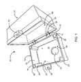
- FIG. 1is a perspective view of a roof top junction box according to the preferred embodiment of the present invention.
- FIG. 2is a perspective view of the present invention, illustrating at least one terminal component secured at an internal storage area of the roof top junction box;
- FIG. 3is a perspective view of a storage unit according to the preferred embodiment of the present invention.
- FIG. 4is a cross-sectional view of a threaded screw element aligned inside a screw hole channel according to the preferred embodiment of the present invention
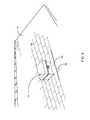
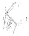
- FIG. 5is a perspective view of the present invention, illustrating the junction box attached to a flashing member
- FIG. 6is a cross-sectional view of a conduit fastening assembly of a multithreaded flute according to the preferred embodiment of the present invention.
- FIG. 7is a perspective view of present invention, illustrating a compression ring and the multithreaded flute inside the storage unit of the junction box;
- FIG. 8is a perspective view of a bottom portion of the present invention, illustrating a second sealing gasket affixed around the bottom conduit port;
- FIG. 9is a perspective view of the present invention, illustrating the roof top junction box in use.
- FIG. 10is a perspective view of another embodiment of the present invention, illustrating a roof top junction box without a bottom conduit port;
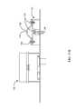
- FIG. 11Ais a top view of yet another embodiment of the present invention, illustrating a satellite dish mount attached to the flashing;
- FIG. 11Bis a side view of the embodiment shown in FIG. 11A ;
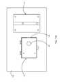
- FIG. 12Ais a perspective view of yet another embodiment of the present invention, illustrating a roof top junction box hanged on an external wall of a building;
- FIG. 12Bis a top plan view of the embodiment shown in FIG. 12A .
- the roof top junction box 10comprises a storage unit 12 and an enclosure 14 .
- the storage unit 12includes an internal storage area 26 and a bottom conduit port 22 .
- the internal storage area 26includes a base surface 24 having a plurality of screw holes 66 designed to connect with a mounting component 30 ( FIG. 2 ).
- the bottom conduit port 22is designed to pass a conduit 58 ( FIG. 5 ) therethrough.
- the junction box 10further comprises a plurality of screw hole channels 16 .
- Each of the plurality of screw hole channels 16is positioned at each of a plurality of peripheral corners 20 of the storage unit 12 .
- the storage unit 12includes a plurality of side walls 72 to secure at least one terminal component 32 ( FIG. 2 ) secured in the internal storage area 26 .
- the at least one terminal component 32is adaptable to connect with the at least one wiring system of a building.
- the enclosure 14is detachably attached to the storage unit 12 utilizing a locking mechanism 18 .
- the enclosure 14provides water proof protection to the at least one terminal component 32 secured in the internal storage area 26 and the roof top portion under the junction box 10 .
- the enclosure 14includes an enclosure area 68 large enough to occupy several terminal components 32 in the internal storage area 26 .
- the storage unit 12 and the enclosure 14have half of the exact height of the junction box 10 which enables an installer's hands to reach inside the box and make the connections.
- the locking mechanism 18is designed to easily disengage the enclosure 14 from the storage unit 12 .
- the locking mechanism 18includes a pair of storage unit hinges 34 and a storage lock 36 attached to the storage unit 12 and a pair of enclosure hinges 38 and an enclosure lock 40 attached to the enclosure 14 .
- the pair of storage unit hinges 34 and the pair of enclosure hinges 38enable the junction box 10 to be opened and closed easily.
- the storage lock 36 and the enclosure lock 40enable the enclosure 14 to get tightly locked with the storage unit 12 thereby preventing the entry of water content inside the storage unit 12 and at the roof top 64 .
- the pair of enclosure hinges 38is shaped such that the enclosure hinges 38 drops over the pair of storage unit hinges 34 when the junction box 10 is in a 180 degree open position. Then, as the pair of enclosure hinges 38 pivots around the pair of storage unit hinges 34 , the pair of enclosure hinges 38 is captivated and locked into place.
- the mounting component 30is adaptable to securely fasten at least one terminal component 32 such as switch, socket and other wiring systems thereon.
- the at least one wiring systemmay be an electrical wiring system, a solar wiring system, a television wiring system from a satellite dish, a cable wiring system carrying internet etc.
- a plurality of interior walls 28separates each of the plurality of screw hole channels 16 from the internal storage area 26 thereby protecting the plurality of screw hole channels 16 from any possible water leakages at the internal storage area 26 and at the roof top portion under the junction box 10 .
- a bottom portion 48( FIG. 8 ) includes a plurality of base ledges 42 ( FIG. 8 ), each positioned below each of the plurality of screw hole channels 16 .
- the plurality of base ledges 42provides proper balance to the junction box 10 during the installation on a roof top 64 ( FIG. 9 ) of a building 74 ( FIG. 9 ).
- the mounting component 30is a din rail which is a standard off the shelf component at the electrical yard that is kind of a universal channel to snap in a variety of conductor units, such as a direct wire to wire unit or a fused wire to wire unit.
- the din railis fastened to the base surface utilizing a plurality of rail fastening means 70 .
- the plurality of screw holes 66tightly secure at least one terminal component 32 inside the storage unit 12 .
- the junction box 10further includes a plurality of press fit flutes 76 aligned inside the plurality of screw hole channels 16 .
- at least two of the plurality of screw hole channels 16are aligned with each of the plurality of press fit flutes 76 .
- the junction box 10is affixed on the rooftop 64 utilizing a plurality of threaded screw elements 56 and a flashing member 50 .
- each of the plurality of threaded screw elements 56extends downwards through each of the plurality of press fit flutes 76 in the at least two of the plurality of screw hole channels 16 .
- the plurality of threaded screw elements 56 and the plurality of press fit flutes 76are designed to align with the flashing member 50 .
- the junction box 10can be directly attached to the roof top 64 thereby improving the stability of the junction box 10 .
- the at least two of the plurality of screw hole channels 16includes a plurality of first sealing gaskets 78 and a plurality of rubber washers 80 .
- Each of the plurality of first sealing gaskets 78is attached to a top portion 84 of each of the plurality of press fit flutes 76 to securely hold each of the plurality of threaded screw elements 56 corresponding to the at least two of the plurality of screw hole channels 16 .
- Each of the plurality of rubber washers 80is positioned at an interior portion 82 of each of the plurality of base ledges 42 corresponding to the at least two of the plurality of screw hole channels 16 .
- a threaded top portion 62 of each of the plurality of threaded screw elements 56firmly holds the threaded screw elements between the first sealing gasket 78 and the rubber washer 80 .
- the plurality of first sealing gaskets 78directs the flow of water towards the roof top 64 of the building 74 thereby preventing the entry of water into the at least two of the plurality of screw hole channels 16 and to the roof top 64 .
- a multithreaded flute 60is aligned with the bottom conduit port 22 and swedged into the flashing member 50 .
- the multithreaded flute 60is designed to tightly pass the conduit 58 through the bottom conduit port 22 and an opening (not shown) at the flashing member 50 utilizing a conduit fastening assembly 86 thereby enabling the conduit 58 to connect with the at least one wiring system of the building 74 ( FIG. 9 ).
- the multithreaded flute 60includes an upper thread portion 88 and a lower thread portion 90 .
- the conduit fastening assembly 86includes a second sealing gasket 44 , a compression ring 52 and a nut 54 .
- the lower thread portion 90utilizes the second sealing gasket 44 to secure the conduit 58 with the flashing member 50 .
- the upper thread portion 88utilizes the compression ring 52 and the nut 54 to tightly pass the conduit 58 through the bottom conduit port 22 and the opening (not shown) at the flashing member 50 to the roof top 64 ( FIG. 9 ) of the building 74 .
- Aforementioned versatile design of the conduit fastening assembly 86facilitates the installation of the junction box 10 on the roof top 64 .
- the installeris not required to go to the roof top 64 and run the conduit 58 to the junction box 10 , rather he could drop the conduit 58 from the top into the roof 64 , where he desires to fix. Thereafter, he can complete the run to the source. This eliminates half of the run around between the roof top 64 and the attic.
- the conduit 58is an electrical metal tubing (EMT).
- FIG. 9shows the junction box in use.
- the mounting component 30is fastened at the internal storage area 26 .
- the at least one terminal component 32is secured at the mounting component 30 .
- the plurality of threaded screw elements 56is aligned in at least two of the plurality of screw hole channels 16 utilizing the plurality of first sealing gaskets 78 , the plurality of rubber washers 80 and the plurality of press fit flutes 76 .
- the plurality of threaded screw elements 56is affixed at the flashing member 50 attached to the roof top 64 .
- the compression ring 52 and the multithreaded flute 60are aligned at the bottom conduit port 22 .
- the conduit 58is inserted through the bottom conduit port 22 and the opening (not shown) at the flashing member 50 . Thereafter, the conduit 58 is tightened with the flashing member 50 utilizing the nut 54 and the second sealing gasket 44 .
- This preferred simple and reliable methodfacilitates the connection between the conduit 58 and the wiring system of the building 74 as depicted in FIG. 9 .
- the roof top junction box 10does not include the conduit 58 for connecting the junction box 10 and the at least one wiring system of the building as shown in FIG. 10 .
- the roof top 64is integrated with roof top panel modules having spatial arrangement. In this arrangement, each panel module is separated spatially and their connection traverses from one group to another before dropping through the roof top 64 . Since there is no conduit 64 being used, this junction box 10 does not include the multithreaded flute 60 and the conduit fastening assembly 86 .
- the wires and cables of the at least one wiring systempass through the sides of the junction box 10 without passing through the conduit 58 .
- FIG. 11Aillustrates another configuration of the roof top junction box 120 illustrating a satellite dish mount 122 attached to a flashing member 124 .
- the flashing member 124is large enough to attach the roof top junction box 120 and the satellite dish mount 122 thereon.
- the roof top junction box 120includes a bottom conduit port 126 .
- a side conduit port 136which is in close proximity to the satellite dish mount 122 allows the wire associated with a satellite dish (not shown) to pass through the roof top 64 in close proximity and eliminates the need for two flashing members 124 .
- FIG. 11Billustrates the satellite dish mount 122 configuration in more detail. As shown in FIG. 11B , three nuts 128 attached to the dish mount 122 .
- the satellite dish mount configurationfurther includes two flutes 130 which pass through the roof top 64 .
- Each of the two flutes 130includes a bar of aluminum 132 mounted on a top portion thereof.
- the bar of aluminum 132includes four holes 134 for attaching a satellite dish (not shown) thereon.
- this configurationacts as a converter from a four hole attachment system of the satellite dish (not shown) to a two hole system thereby reducing the number of holes that must be punched through the roof top 64 .
- the two holes punched for the two flutes 130 going through the roof top 64will each go into a rafter.
- only two of the four fluteswould hit the rafter and the other two flutes 130 would not connect with the rafter.
- FIGS. 12A and 12BYet another configuration of a roof top junction box 140 is illustrated in FIGS. 12A and 12B .
- the roof top junction box 140adaptable to hang on an exterior wall 142 of a building 144 is illustrated.
- the roof top junction box 140is designed to line up with the exterior wall 142 of the building 144 .
- This type of configurationis beneficial for people who do not want to penetrate through the roof top 64 over a living space and who do not want to install the junction box 10 in the attic thereby getting rid of the very ugly overhang wrap around the conduit 58 .
- the eve drop configurationenables a wiring system 146 to go through an overhang portion 148 and just drops down the exterior wall 142 of the building 144 .
Landscapes
- Engineering & Computer Science (AREA)
- Microelectronics & Electronic Packaging (AREA)
- Architecture (AREA)
- Civil Engineering (AREA)
- Structural Engineering (AREA)
- Casings For Electric Apparatus (AREA)
- Connection Or Junction Boxes (AREA)
- Installation Of Indoor Wiring (AREA)
Abstract
Description
Claims (36)
Priority Applications (4)
| Application Number | Priority Date | Filing Date | Title |
|---|---|---|---|
| US14/885,867US9496697B1 (en) | 2015-10-16 | 2015-10-16 | Roof top junction box |
| PCT/US2016/055627WO2017066064A1 (en) | 2015-10-16 | 2016-10-06 | Roof top junction box |
| US15/349,021US9742173B2 (en) | 2015-10-16 | 2016-11-11 | Roof top junction box |
| US15/679,061US9966745B2 (en) | 2015-10-16 | 2017-08-16 | Roof top junction box |
Applications Claiming Priority (1)
| Application Number | Priority Date | Filing Date | Title |
|---|---|---|---|
| US14/885,867US9496697B1 (en) | 2015-10-16 | 2015-10-16 | Roof top junction box |
Related Child Applications (1)
| Application Number | Title | Priority Date | Filing Date |
|---|---|---|---|
| US15/349,021ContinuationUS9742173B2 (en) | 2015-10-16 | 2016-11-11 | Roof top junction box |
Publications (1)
| Publication Number | Publication Date |
|---|---|
| US9496697B1true US9496697B1 (en) | 2016-11-15 |
Family
ID=57235078
Family Applications (3)
| Application Number | Title | Priority Date | Filing Date |
|---|---|---|---|
| US14/885,867ActiveUS9496697B1 (en) | 2015-10-16 | 2015-10-16 | Roof top junction box |
| US15/349,021ActiveUS9742173B2 (en) | 2015-10-16 | 2016-11-11 | Roof top junction box |
| US15/679,061ActiveUS9966745B2 (en) | 2015-10-16 | 2017-08-16 | Roof top junction box |
Family Applications After (2)
| Application Number | Title | Priority Date | Filing Date |
|---|---|---|---|
| US15/349,021ActiveUS9742173B2 (en) | 2015-10-16 | 2016-11-11 | Roof top junction box |
| US15/679,061ActiveUS9966745B2 (en) | 2015-10-16 | 2017-08-16 | Roof top junction box |
Country Status (2)
| Country | Link |
|---|---|
| US (3) | US9496697B1 (en) |
| WO (1) | WO2017066064A1 (en) |
Cited By (34)
| Publication number | Priority date | Publication date | Assignee | Title |
|---|---|---|---|---|
| US10230227B1 (en) | 2018-04-26 | 2019-03-12 | Sasquatch Solar, LLC | Outdoor junction box |
| CN109578430A (en)* | 2018-12-17 | 2019-04-05 | 苏州曼德克光电有限公司 | A kind of compartment connects hinge and preparation method thereof |
| US20190150305A1 (en)* | 2017-11-16 | 2019-05-16 | Yazaki Corporation | Accommodation box and electronic component unit |
| US10505354B2 (en) | 2018-04-26 | 2019-12-10 | Sasquatch Solar, LLC | Junction box |
| US10594121B2 (en)* | 2018-07-09 | 2020-03-17 | Vynckier Enclosure Systems, Inc. | Weatherproof multipurpose enclosure with integrated flashing |
| US20200119533A1 (en)* | 2018-04-26 | 2020-04-16 | Sasquatch Solar, LLC | Junction box |
| US20200382053A1 (en)* | 2019-05-31 | 2020-12-03 | Sunpower Corporation | Junction box for a photovoltaic module mounting assembly |
| US20210044097A1 (en)* | 2019-08-09 | 2021-02-11 | Leviton Manufacturing Co., Inc. | Use of flame resistant material with audio/video, information and communication technology equipment enclosure |
| USD917400S1 (en) | 2019-01-28 | 2021-04-27 | Sasquatch Solar, LLC | Junction box |
| US11069212B2 (en)* | 2017-04-03 | 2021-07-20 | Minimax Gmbh & Co. Kg | Housing for a fire alarm and/or extinguishing control station |
| WO2022011242A1 (en)* | 2020-07-10 | 2022-01-13 | Hubbell Incorporated | Modular junction box downlight luminaire |
| US11228167B2 (en) | 2018-11-13 | 2022-01-18 | Leviton Manufacturing Co., Inc. | Adjustable insert system for wall-mounted enclosures |
| US20220085585A1 (en)* | 2020-09-15 | 2022-03-17 | Easy Solar Products, Llc | Junction Box |
| US11333179B2 (en) | 2011-12-29 | 2022-05-17 | Rmh Tech Llc | Mounting device for nail strip panels |
| US20220263460A1 (en)* | 2021-02-18 | 2022-08-18 | Armando Jimenez | Solar Power Junction Box Assembly |
| US11437794B1 (en) | 2021-11-04 | 2022-09-06 | E & I Sales Co. | Delivery device for rooftop equipment and systems and method of installation |
| US11512474B2 (en) | 2020-03-16 | 2022-11-29 | Rmh Tech Llc | Mounting device for a metal roof |
| US11573033B2 (en) | 2016-07-29 | 2023-02-07 | Rmh Tech Llc | Trapezoidal rib mounting bracket with flexible legs |
| US11581717B1 (en)* | 2021-11-02 | 2023-02-14 | Esdec, Inc. | Mountable electrical enclosure with conduit passthrough |
| US11616468B2 (en) | 2018-03-21 | 2023-03-28 | Rmh Tech Llc | PV module mounting assembly with clamp/standoff arrangement |
| USD988309S1 (en)* | 2021-03-08 | 2023-06-06 | Interface Corporation | Data processing device |
| US11668332B2 (en) | 2018-12-14 | 2023-06-06 | Rmh Tech Llc | Mounting device for nail strip panels |
| US11757269B2 (en) | 2021-01-28 | 2023-09-12 | Tyler Uebelhoer | Electrical junction box for installation on metal roofs to accommodate internal wiring of solar panels |
| US11774143B2 (en) | 2017-10-09 | 2023-10-03 | Rmh Tech Llc | Rail assembly with invertible side-mount adapter for direct and indirect mounting applications |
| US11788291B2 (en) | 2020-03-17 | 2023-10-17 | Rmh Tech Llc | Mounting device for controlling uplift of a metal roof |
| US11808043B2 (en) | 2016-10-31 | 2023-11-07 | Rmh Tech Llc | Metal panel electrical bonding clip |
| US11885139B2 (en) | 2011-02-25 | 2024-01-30 | Rmh Tech Llc | Mounting device for building surfaces having elongated mounting slot |
| US20240039263A1 (en)* | 2022-03-30 | 2024-02-01 | Bmic Llc | Systems and apparatuses for a modular electronics roofing attachment and methods of use thereof |
| USD1015279S1 (en) | 2018-07-09 | 2024-02-20 | Hoffman Enclosures Inc. | Rooftop junction box |
| US20240291256A1 (en)* | 2023-02-27 | 2024-08-29 | Sunrun Inc. | Enclosure assembly with housing |
| US12203496B2 (en) | 2020-07-09 | 2025-01-21 | Rmh Tech Llc | Mounting system, device, and method |
| US12255445B2 (en) | 2022-11-03 | 2025-03-18 | Easy Solar Products, Inc. | Rail-mountable junction box |
| USD1073625S1 (en)* | 2023-08-09 | 2025-05-06 | Yueqing Daier Electron Co., Ltd. | Power outlet box |
| USD1075493S1 (en) | 2022-07-06 | 2025-05-20 | Rmh Tech Llc | Clamp for a photovoltaic module mounting assembly |
Families Citing this family (7)
| Publication number | Priority date | Publication date | Assignee | Title |
|---|---|---|---|---|
| AU366661S (en)* | 2015-07-10 | 2016-01-20 | Hubbell Ltd | Boxes for electrical elements |
| JP6095841B1 (en)* | 2016-10-24 | 2017-03-15 | 昭和機器工業株式会社 | Air shelter for electrical equipment |
| CN107492852B (en)* | 2017-09-29 | 2022-09-27 | 宁波广瑞通信技术有限公司 | Metal junction box |
| GB2572575B (en) | 2018-04-03 | 2021-01-20 | Electrix International Ltd | An enclosure for protecting electrical components and cables |
| USD1002560S1 (en) | 2019-11-25 | 2023-10-24 | Fibox Oy Ab | Protective casing for electrical device |
| CN216214188U (en)* | 2021-10-18 | 2022-04-05 | 阳光电源股份有限公司 | PV terminal assemblies and electrical installations |
| USD1094286S1 (en)* | 2021-11-29 | 2025-09-23 | YouSolar, Inc. | Power storage system |
Citations (34)
| Publication number | Priority date | Publication date | Assignee | Title |
|---|---|---|---|---|
| US284139A (en) | 1883-08-28 | Testing-box for underground electric cables | ||
| US794742A (en) | 1903-07-22 | 1905-07-18 | Henry E Procunier | Soldering-nipple for electric cables. |
| US1131399A (en) | 1911-06-23 | 1915-03-09 | Handy Mfg Company | Outlet-box. |
| US1695633A (en) | 1925-06-06 | 1928-12-18 | Alfred T Clark | Junction-box mounting |
| US1774934A (en) | 1928-09-25 | 1930-09-02 | Mangin James | Outlet box and support |
| US1782546A (en) | 1927-09-12 | 1930-11-25 | Roach Appleton Mfg Company | Box-supporting ear |
| US1828064A (en) | 1928-03-12 | 1931-10-20 | Beaumont C Paine | Electrical outlet box |
| US1833306A (en) | 1927-07-16 | 1931-11-24 | Rieke Metal Products Corp | Barrel |
| US1928198A (en) | 1932-07-26 | 1933-09-26 | Thomas & Betts Corp | Floor box |
| US2299674A (en) | 1940-01-04 | 1942-10-20 | Jr Merritt B Austin | Receptacle and mounting therefor |
| US2360359A (en) | 1941-04-26 | 1944-10-17 | Porcelain Steels Inc | Conduit connection for tanks |
| US2440372A (en) | 1947-01-16 | 1948-04-27 | Jackson Wilbur | Clamp for barrel pumps |
| US2674470A (en) | 1950-09-29 | 1954-04-06 | Arthur I Appleton | Electrical connector and method of making same |
| US2861120A (en) | 1955-10-24 | 1958-11-18 | Nat Acme Co | Junction box assembly |
| US3215303A (en) | 1963-02-14 | 1965-11-02 | North & Judd Mfg Co | Closure for openings in the walls of electrical outlet boxes and the like |
| US4151363A (en) | 1976-12-20 | 1979-04-24 | Nichols Wayne L | Method and apparatus for joining electrical conductors to junction boxes |
| US4420022A (en) | 1981-04-06 | 1983-12-13 | Landry George H | Liquefied gas filling device |
| US5067685A (en) | 1985-09-05 | 1991-11-26 | Fibrelon, Inc. | Modular electrical box mounting system |
| US5646371A (en)* | 1993-04-23 | 1997-07-08 | Thomas & Betts Corporation | Electrical outlet box and plate therefor incorporating a rear support bracket |
| US5698820A (en)* | 1995-06-27 | 1997-12-16 | Parsec Products, Inc. | Method and apparatus for junction box and conduit support |
| US6516741B1 (en)* | 2000-09-12 | 2003-02-11 | Hadley Products | Leak proof apparatus for mounting components to panels |
| US6526701B2 (en)* | 2000-07-03 | 2003-03-04 | Vermont Slate & Copper Services, Inc. | Roof mount |
| US6734356B1 (en)* | 1999-08-13 | 2004-05-11 | Arlington Industries, Inc. | Prepackaged mounting assembly and bracket combination |
| US7041901B2 (en) | 2003-10-28 | 2006-05-09 | B-K Lighting, Inc. | Method and apparatus for providing an environmental barrier between an interior and exterior of an electrical enclosure using a plug and seal |
| US7078623B1 (en) | 2005-11-30 | 2006-07-18 | Sheehan Robert K | Electrical conduit to junction box connection system |
| US7128345B2 (en)* | 2002-07-26 | 2006-10-31 | Anton Hummel Verwaltungs Gmbh | Terminal connection comprising a threaded sleeve, a counter-sleeve and a terminal insert |
| US7154040B1 (en) | 2006-01-09 | 2006-12-26 | Tompkins Philip M | Support bracket for electrical junction box |
| US7762027B1 (en)* | 2006-09-28 | 2010-07-27 | Wentworth Stuart H | System for attaching an article to a roof and method of use |
| US20100307074A1 (en)* | 2010-03-19 | 2010-12-09 | Brian Cecil Stearns | Roofing system and method |
| US7861485B1 (en)* | 2007-06-26 | 2011-01-04 | Wentworth Stuart H | Method for installing a stanchion on a tile roof and system therefor |
| US8158884B2 (en)* | 2008-11-17 | 2012-04-17 | Thomas & Betts International, Inc. | Angled slots for installation of outdoor metallic boxes |
| US8177086B2 (en) | 2009-07-24 | 2012-05-15 | Ipex Technologies Inc. | Electrical box and stand and method for using same |
| US8479455B2 (en)* | 2010-10-14 | 2013-07-09 | D Three Enterprises | Flashing assembly |
| US8701360B2 (en) | 2007-05-25 | 2014-04-22 | General Electric Company | Method and apparatus for assembling photovoltaic modules |
Family Cites Families (5)
| Publication number | Priority date | Publication date | Assignee | Title |
|---|---|---|---|---|
| DE20311183U1 (en)* | 2003-07-21 | 2004-07-08 | Tyco Electronics Amp Gmbh | Junction box for a solar panel and solar panel |
| US7005578B2 (en)* | 2004-06-09 | 2006-02-28 | Arlington Industries, Inc. | Rainproof recessed outlet box |
| US7626118B1 (en)* | 2007-05-07 | 2009-12-01 | Capozzi Stephen J | Weather-proof junction box for exterior use |
| US7833033B2 (en)* | 2008-04-16 | 2010-11-16 | Molex Incorporated | Solar panel junction box and components thereof |
| US9080792B2 (en)* | 2013-07-31 | 2015-07-14 | Ironridge, Inc. | Method and apparatus for mounting solar panels |
- 2015
- 2015-10-16USUS14/885,867patent/US9496697B1/enactiveActive
- 2016
- 2016-10-06WOPCT/US2016/055627patent/WO2017066064A1/ennot_activeCeased
- 2016-11-11USUS15/349,021patent/US9742173B2/enactiveActive
- 2017
- 2017-08-16USUS15/679,061patent/US9966745B2/enactiveActive
Patent Citations (34)
| Publication number | Priority date | Publication date | Assignee | Title |
|---|---|---|---|---|
| US284139A (en) | 1883-08-28 | Testing-box for underground electric cables | ||
| US794742A (en) | 1903-07-22 | 1905-07-18 | Henry E Procunier | Soldering-nipple for electric cables. |
| US1131399A (en) | 1911-06-23 | 1915-03-09 | Handy Mfg Company | Outlet-box. |
| US1695633A (en) | 1925-06-06 | 1928-12-18 | Alfred T Clark | Junction-box mounting |
| US1833306A (en) | 1927-07-16 | 1931-11-24 | Rieke Metal Products Corp | Barrel |
| US1782546A (en) | 1927-09-12 | 1930-11-25 | Roach Appleton Mfg Company | Box-supporting ear |
| US1828064A (en) | 1928-03-12 | 1931-10-20 | Beaumont C Paine | Electrical outlet box |
| US1774934A (en) | 1928-09-25 | 1930-09-02 | Mangin James | Outlet box and support |
| US1928198A (en) | 1932-07-26 | 1933-09-26 | Thomas & Betts Corp | Floor box |
| US2299674A (en) | 1940-01-04 | 1942-10-20 | Jr Merritt B Austin | Receptacle and mounting therefor |
| US2360359A (en) | 1941-04-26 | 1944-10-17 | Porcelain Steels Inc | Conduit connection for tanks |
| US2440372A (en) | 1947-01-16 | 1948-04-27 | Jackson Wilbur | Clamp for barrel pumps |
| US2674470A (en) | 1950-09-29 | 1954-04-06 | Arthur I Appleton | Electrical connector and method of making same |
| US2861120A (en) | 1955-10-24 | 1958-11-18 | Nat Acme Co | Junction box assembly |
| US3215303A (en) | 1963-02-14 | 1965-11-02 | North & Judd Mfg Co | Closure for openings in the walls of electrical outlet boxes and the like |
| US4151363A (en) | 1976-12-20 | 1979-04-24 | Nichols Wayne L | Method and apparatus for joining electrical conductors to junction boxes |
| US4420022A (en) | 1981-04-06 | 1983-12-13 | Landry George H | Liquefied gas filling device |
| US5067685A (en) | 1985-09-05 | 1991-11-26 | Fibrelon, Inc. | Modular electrical box mounting system |
| US5646371A (en)* | 1993-04-23 | 1997-07-08 | Thomas & Betts Corporation | Electrical outlet box and plate therefor incorporating a rear support bracket |
| US5698820A (en)* | 1995-06-27 | 1997-12-16 | Parsec Products, Inc. | Method and apparatus for junction box and conduit support |
| US6734356B1 (en)* | 1999-08-13 | 2004-05-11 | Arlington Industries, Inc. | Prepackaged mounting assembly and bracket combination |
| US6526701B2 (en)* | 2000-07-03 | 2003-03-04 | Vermont Slate & Copper Services, Inc. | Roof mount |
| US6516741B1 (en)* | 2000-09-12 | 2003-02-11 | Hadley Products | Leak proof apparatus for mounting components to panels |
| US7128345B2 (en)* | 2002-07-26 | 2006-10-31 | Anton Hummel Verwaltungs Gmbh | Terminal connection comprising a threaded sleeve, a counter-sleeve and a terminal insert |
| US7041901B2 (en) | 2003-10-28 | 2006-05-09 | B-K Lighting, Inc. | Method and apparatus for providing an environmental barrier between an interior and exterior of an electrical enclosure using a plug and seal |
| US7078623B1 (en) | 2005-11-30 | 2006-07-18 | Sheehan Robert K | Electrical conduit to junction box connection system |
| US7154040B1 (en) | 2006-01-09 | 2006-12-26 | Tompkins Philip M | Support bracket for electrical junction box |
| US7762027B1 (en)* | 2006-09-28 | 2010-07-27 | Wentworth Stuart H | System for attaching an article to a roof and method of use |
| US8701360B2 (en) | 2007-05-25 | 2014-04-22 | General Electric Company | Method and apparatus for assembling photovoltaic modules |
| US7861485B1 (en)* | 2007-06-26 | 2011-01-04 | Wentworth Stuart H | Method for installing a stanchion on a tile roof and system therefor |
| US8158884B2 (en)* | 2008-11-17 | 2012-04-17 | Thomas & Betts International, Inc. | Angled slots for installation of outdoor metallic boxes |
| US8177086B2 (en) | 2009-07-24 | 2012-05-15 | Ipex Technologies Inc. | Electrical box and stand and method for using same |
| US20100307074A1 (en)* | 2010-03-19 | 2010-12-09 | Brian Cecil Stearns | Roofing system and method |
| US8479455B2 (en)* | 2010-10-14 | 2013-07-09 | D Three Enterprises | Flashing assembly |
Cited By (78)
| Publication number | Priority date | Publication date | Assignee | Title |
|---|---|---|---|---|
| US11885139B2 (en) | 2011-02-25 | 2024-01-30 | Rmh Tech Llc | Mounting device for building surfaces having elongated mounting slot |
| US12018861B2 (en) | 2011-12-29 | 2024-06-25 | Rmh Tech Llc | Mounting device for nail strip panels |
| US11333179B2 (en) | 2011-12-29 | 2022-05-17 | Rmh Tech Llc | Mounting device for nail strip panels |
| US12044443B2 (en) | 2016-07-29 | 2024-07-23 | Rmh Tech Llc | Trapezoidal rib mounting bracket with flexible legs |
| US11573033B2 (en) | 2016-07-29 | 2023-02-07 | Rmh Tech Llc | Trapezoidal rib mounting bracket with flexible legs |
| US11808043B2 (en) | 2016-10-31 | 2023-11-07 | Rmh Tech Llc | Metal panel electrical bonding clip |
| US11069212B2 (en)* | 2017-04-03 | 2021-07-20 | Minimax Gmbh & Co. Kg | Housing for a fire alarm and/or extinguishing control station |
| US11774143B2 (en) | 2017-10-09 | 2023-10-03 | Rmh Tech Llc | Rail assembly with invertible side-mount adapter for direct and indirect mounting applications |
| US20190150305A1 (en)* | 2017-11-16 | 2019-05-16 | Yazaki Corporation | Accommodation box and electronic component unit |
| US12231081B2 (en) | 2018-03-21 | 2025-02-18 | Rmh Tech Llc | PV module mounting assembly with clamp/standoff arrangement |
| US11616468B2 (en) | 2018-03-21 | 2023-03-28 | Rmh Tech Llc | PV module mounting assembly with clamp/standoff arrangement |
| US20240178643A1 (en)* | 2018-04-26 | 2024-05-30 | Easy Solar Products, Inc. | Junction box with integral flashing |
| US20240162698A1 (en)* | 2018-04-26 | 2024-05-16 | Easy Solar Products, Inc. | Junction box with drill zone interior to sealant |
| US12003085B2 (en)* | 2018-04-26 | 2024-06-04 | Easy Solar Products, Inc. | Junction box with a flashing and weep holes |
| US11695261B2 (en)* | 2018-04-26 | 2023-07-04 | Easy Solar Products, Inc. | Groove indicated junction box |
| US11996685B1 (en)* | 2018-04-26 | 2024-05-28 | Easy Solar Products, Inc. | Junction box with side drill zones |
| US11996684B1 (en)* | 2018-04-26 | 2024-05-28 | Easy Solar Products, Inc. | Junction box with integral flashing |
| US11990735B1 (en)* | 2018-04-26 | 2024-05-21 | Easy Solar Products, Inc. | Junction box with lid secured from the top |
| US20240195159A1 (en)* | 2018-04-26 | 2024-06-13 | Easy Solar Products, Inc. | Roof-mounted junction box with lid |
| US10230227B1 (en) | 2018-04-26 | 2019-03-12 | Sasquatch Solar, LLC | Outdoor junction box |
| US20240186779A1 (en)* | 2018-04-26 | 2024-06-06 | Easy Solar Products, Inc. | Junction box with side drill zones |
| US11984715B1 (en)* | 2018-04-26 | 2024-05-14 | Easy Solar Products, Inc. | Junction box with drill zone interior to sealant |
| US20240154397A1 (en)* | 2018-04-26 | 2024-05-09 | Easy Solar Products, Inc. | Junction box with lid secured from the top |
| US20240154398A1 (en)* | 2018-04-26 | 2024-05-09 | Easy Solar Products, Inc. | Junction box with protection bosses |
| US11515693B2 (en)* | 2018-04-26 | 2022-11-29 | Easy Solar Products, Llc | Groove indicated junction box |
| US20240106214A1 (en)* | 2018-04-26 | 2024-03-28 | Easy Solar Products, Inc. | Junction box with lid retention system |
| US12015257B1 (en)* | 2018-04-26 | 2024-06-18 | Easy Solar Products, Inc. | Roof-mounted junction box with lid |
| US12021360B2 (en)* | 2018-04-26 | 2024-06-25 | Easy Solar Products, Inc. | Junction box with lid retention system |
| US20200119533A1 (en)* | 2018-04-26 | 2020-04-16 | Sasquatch Solar, LLC | Junction box |
| US10505354B2 (en) | 2018-04-26 | 2019-12-10 | Sasquatch Solar, LLC | Junction box |
| US12438350B2 (en) | 2018-04-26 | 2025-10-07 | Easy Solar Products, Inc. | Junction box with compressed sealant |
| US11349288B2 (en) | 2018-07-09 | 2022-05-31 | Hoffmann Enclosures Inc. | Weatherproof multipurpose enclosure with integrated flashing |
| US10594121B2 (en)* | 2018-07-09 | 2020-03-17 | Vynckier Enclosure Systems, Inc. | Weatherproof multipurpose enclosure with integrated flashing |
| USD966199S1 (en) | 2018-07-09 | 2022-10-11 | Hoffman Enclosures Inc. | Weatherproof multipurpose enclosure |
| USD926703S1 (en) | 2018-07-09 | 2021-08-03 | Hoffmann Enclosures Inc. | Weatherproof multipurpose enclosure |
| US12068592B2 (en) | 2018-07-09 | 2024-08-20 | Hoffman Enclosures Inc. | Weatherproof multipurpose enclosure with integrated flashing |
| US20200176963A1 (en)* | 2018-07-09 | 2020-06-04 | Vynckier Enclosure Systems, Inc. | Weatherproof multipurpose enclosure with integrated flashing |
| USD1015279S1 (en) | 2018-07-09 | 2024-02-20 | Hoffman Enclosures Inc. | Rooftop junction box |
| US10804685B2 (en) | 2018-07-09 | 2020-10-13 | Vynckier Enclosure Systems, Inc. | Weatherproof multipurpose enclosure with integrated flashing |
| US20220085586A1 (en)* | 2018-11-13 | 2022-03-17 | Leviton Manufacturing Co., Inc. | Adjustable insert system for wall-mounted enclosures |
| US12308630B2 (en)* | 2018-11-13 | 2025-05-20 | Leviton Manufacturing Co., Inc. | Adjustable insert system for wall-mounted enclosures |
| US11228167B2 (en) | 2018-11-13 | 2022-01-18 | Leviton Manufacturing Co., Inc. | Adjustable insert system for wall-mounted enclosures |
| US12320375B2 (en) | 2018-12-14 | 2025-06-03 | Rmh Tech Llc | Mounting device for nail strip panels |
| US11668332B2 (en) | 2018-12-14 | 2023-06-06 | Rmh Tech Llc | Mounting device for nail strip panels |
| CN109578430A (en)* | 2018-12-17 | 2019-04-05 | 苏州曼德克光电有限公司 | A kind of compartment connects hinge and preparation method thereof |
| CN109578430B (en)* | 2018-12-17 | 2024-05-07 | 苏州曼德克光电有限公司 | Waterproof box connection hinge and manufacturing method thereof |
| USD917400S1 (en) | 2019-01-28 | 2021-04-27 | Sasquatch Solar, LLC | Junction box |
| US20200382053A1 (en)* | 2019-05-31 | 2020-12-03 | Sunpower Corporation | Junction box for a photovoltaic module mounting assembly |
| US20250274073A1 (en)* | 2019-05-31 | 2025-08-28 | Unirac, Inc. | Rail mounted junction box |
| US12034398B2 (en)* | 2019-05-31 | 2024-07-09 | Sunpower Corporation | Junction box for a photovoltaic module mounting assembly |
| US20210044097A1 (en)* | 2019-08-09 | 2021-02-11 | Leviton Manufacturing Co., Inc. | Use of flame resistant material with audio/video, information and communication technology equipment enclosure |
| US11038328B2 (en)* | 2019-08-09 | 2021-06-15 | Leviton Manufacturing Co., Inc. | Use of flame resistant material with audio/video, information and communication technology equipment enclosure |
| US11670927B2 (en) | 2019-08-09 | 2023-06-06 | Leviton Manufacturing Co., Inc. | Use of flame resistant material with audio/video, information and communication technology equipment enclosure |
| US12305397B2 (en) | 2020-03-16 | 2025-05-20 | Rmh Tech Llc | Mounting device for a metal roof |
| US11512474B2 (en) | 2020-03-16 | 2022-11-29 | Rmh Tech Llc | Mounting device for a metal roof |
| US11739529B2 (en) | 2020-03-16 | 2023-08-29 | Rmh Tech Llc | Mounting device for a metal roof |
| US11965337B2 (en) | 2020-03-16 | 2024-04-23 | Rmh Tech Llc | Mounting device for a metal roof |
| US11788291B2 (en) | 2020-03-17 | 2023-10-17 | Rmh Tech Llc | Mounting device for controlling uplift of a metal roof |
| US12203496B2 (en) | 2020-07-09 | 2025-01-21 | Rmh Tech Llc | Mounting system, device, and method |
| WO2022011242A1 (en)* | 2020-07-10 | 2022-01-13 | Hubbell Incorporated | Modular junction box downlight luminaire |
| US11530805B2 (en) | 2020-07-10 | 2022-12-20 | Hubbell Lighting, Inc. | Modular junction box for downlight luminaire |
| US11848549B2 (en)* | 2020-09-15 | 2023-12-19 | Easy Solar Products, Inc. | Junction box with flashing for a tile surface |
| US20240128731A1 (en)* | 2020-09-15 | 2024-04-18 | Easy Solar Products, Inc. | Junction box with flashing for a tile surface of a roof |
| US12300988B2 (en)* | 2020-09-15 | 2025-05-13 | Easy Solar Products, Inc. | Junction box with flashing for a tile surface of a roof |
| US20220085585A1 (en)* | 2020-09-15 | 2022-03-17 | Easy Solar Products, Llc | Junction Box |
| US11757269B2 (en) | 2021-01-28 | 2023-09-12 | Tyler Uebelhoer | Electrical junction box for installation on metal roofs to accommodate internal wiring of solar panels |
| US20220263460A1 (en)* | 2021-02-18 | 2022-08-18 | Armando Jimenez | Solar Power Junction Box Assembly |
| USD988309S1 (en)* | 2021-03-08 | 2023-06-06 | Interface Corporation | Data processing device |
| US11916364B2 (en)* | 2021-11-02 | 2024-02-27 | Enstall Us, Inc. | Mountable electrical enclosure with conduit passthrough |
| US20230208123A1 (en)* | 2021-11-02 | 2023-06-29 | Esdec, Inc. | Mountable electrical enclosure with conduit passthrough |
| US11581717B1 (en)* | 2021-11-02 | 2023-02-14 | Esdec, Inc. | Mountable electrical enclosure with conduit passthrough |
| US11437794B1 (en) | 2021-11-04 | 2022-09-06 | E & I Sales Co. | Delivery device for rooftop equipment and systems and method of installation |
| US20240039263A1 (en)* | 2022-03-30 | 2024-02-01 | Bmic Llc | Systems and apparatuses for a modular electronics roofing attachment and methods of use thereof |
| USD1075493S1 (en) | 2022-07-06 | 2025-05-20 | Rmh Tech Llc | Clamp for a photovoltaic module mounting assembly |
| US12255445B2 (en) | 2022-11-03 | 2025-03-18 | Easy Solar Products, Inc. | Rail-mountable junction box |
| US12142902B2 (en)* | 2023-02-27 | 2024-11-12 | Sunrun Inc. | Enclosure assembly with housing |
| US20240291256A1 (en)* | 2023-02-27 | 2024-08-29 | Sunrun Inc. | Enclosure assembly with housing |
| USD1073625S1 (en)* | 2023-08-09 | 2025-05-06 | Yueqing Daier Electron Co., Ltd. | Power outlet box |
Also Published As
| Publication number | Publication date |
|---|---|
| US20170110863A1 (en) | 2017-04-20 |
| US9966745B2 (en) | 2018-05-08 |
| US20170346267A1 (en) | 2017-11-30 |
| US9742173B2 (en) | 2017-08-22 |
| WO2017066064A1 (en) | 2017-04-20 |
Similar Documents
| Publication | Publication Date | Title |
|---|---|---|
| US9966745B2 (en) | Roof top junction box | |
| US9819166B1 (en) | Weather-proof junction box with pan for circuit board | |
| US9680409B2 (en) | Adjustable combined flashing and mounting apparatus and method of mounting to be used therewith | |
| US9438161B2 (en) | Bracket for connection of a junction box to photovoltaic panels | |
| US6414241B1 (en) | Enclosure for interfacing electrical and control or communication devices | |
| US7626118B1 (en) | Weather-proof junction box for exterior use | |
| US5541363A (en) | Wet-environment electrical juncton box and method of making | |
| US20210273434A1 (en) | Weatherproof electrical enclosure with reinforcement | |
| US20080237227A1 (en) | Electrical junction assemblies for coupling electrical fixtures to suspending ceiling grids | |
| US7183483B1 (en) | Cover for surface mounted alarm unit | |
| WO2017155855A1 (en) | Junction box | |
| US7022912B1 (en) | Conduit rack junction box | |
| MX2007001826A (en) | Electrical enclosure assembly and moisture-resistant mount therefor. | |
| US11916364B2 (en) | Mountable electrical enclosure with conduit passthrough | |
| US20160261055A1 (en) | Integrated electrical assembly for housing modular units and related components thereof | |
| US20050167135A1 (en) | Electrical panel support stand | |
| US20240204499A1 (en) | Mountable electrical enclosure with conduit passthrough | |
| KR101522389B1 (en) | Raceway for installing lighting apparatus or CCTV camera | |
| JP3555029B2 (en) | Bus duct | |
| RU2787407C1 (en) | Universal mounting box-bracket for mounting camcorders on flat, cylindrical and multifaceted surfaces | |
| US20240266814A1 (en) | Push to Connect Electrical Connector with Integral Release | |
| EP3421870B1 (en) | Ceiling-mounted and wall-mounted dual-purpose lamp kit and installation methods of the lamps | |
| JP2006020435A (en) | Joint box incorporated with detachable aggregated wire connector equipped with detachable fittings for hook ceiling or the like, and fitting method of the joint box | |
| JPH09250776A (en) | Ceiling-mounted air conditioner | |
| JP2004088999A (en) | Bus duct |
Legal Events
| Date | Code | Title | Description |
|---|---|---|---|
| STCF | Information on status: patent grant | Free format text:PATENTED CASE | |
| AS | Assignment | Owner name:IMAGEINEERING PLUS PLUS, LLC, TEXAS Free format text:ASSIGNMENT OF ASSIGNORS INTEREST;ASSIGNOR:WENTWORTH, STUART;REEL/FRAME:043296/0843 Effective date:20151016 | |
| AS | Assignment | Owner name:IMAGINEERING PLUS PLUS, LLC, TEXAS Free format text:ASSIGNMENT OF ASSIGNORS INTEREST;ASSIGNOR:WENTWORTH, STUART;REEL/FRAME:050129/0149 Effective date:20151016 | |
| AS | Assignment | Owner name:WENCON DEVELOPMENT, INC., CALIFORNIA Free format text:ASSIGNMENT OF ASSIGNORS INTEREST;ASSIGNOR:IMAGINEERING PLUS PLUS, LLC;REEL/FRAME:050158/0914 Effective date:20190823 | |
| MAFP | Maintenance fee payment | Free format text:PAYMENT OF MAINTENANCE FEE, 4TH YR, SMALL ENTITY (ORIGINAL EVENT CODE: M2551); ENTITY STATUS OF PATENT OWNER: SMALL ENTITY Year of fee payment:4 | |
| AS | Assignment | Owner name:WILMINGTON TRUST, NATIONAL ASSOCIATION, DELAWARE Free format text:SECURITY INTEREST;ASSIGNORS:ECOFASTEN SOLAR, LLC;IRONRIDGE, INC.;PANELCLAW, INC.;AND OTHERS;REEL/FRAME:057365/0001 Effective date:20210830 | |
| AS | Assignment | Owner name:WENCON DEVELOPMENT, INC. D/B/A QUICK MOUNT PV, CALIFORNIA Free format text:CORRECTIVE ASSIGNMENT TO CORRECT THE NAME OF ASSIGNEE PREVIOUSLY RECORDED ON REEL 050158 FRAME 0914. ASSIGNOR(S) HEREBY CONFIRMS THE ASSIGNMENT;ASSIGNOR:IMAGINEERING PLUS PLUS, LLC;REEL/FRAME:064700/0100 Effective date:20190823 | |
| FEPP | Fee payment procedure | Free format text:ENTITY STATUS SET TO UNDISCOUNTED (ORIGINAL EVENT CODE: BIG.); ENTITY STATUS OF PATENT OWNER: LARGE ENTITY | |
| MAFP | Maintenance fee payment | Free format text:PAYMENT OF MAINTENANCE FEE, 8TH YEAR, LARGE ENTITY (ORIGINAL EVENT CODE: M1552); ENTITY STATUS OF PATENT OWNER: LARGE ENTITY Year of fee payment:8 |