US9495814B2 - Vehicle fault early warning system - Google Patents
Vehicle fault early warning systemDownload PDFInfo
- Publication number
- US9495814B2 US9495814B2US14/309,238US201414309238AUS9495814B2US 9495814 B2US9495814 B2US 9495814B2US 201414309238 AUS201414309238 AUS 201414309238AUS 9495814 B2US9495814 B2US 9495814B2
- Authority
- US
- United States
- Prior art keywords
- vehicle
- fault
- vehicles
- transmitting
- warning notification
- Prior art date
- Legal status (The legal status is an assumption and is not a legal conclusion. Google has not performed a legal analysis and makes no representation as to the accuracy of the status listed.)
- Active, expires
Links
- 238000012545processingMethods0.000claimsabstractdescription28
- 238000000034methodMethods0.000claimsdescription25
- 238000012544monitoring processMethods0.000claimsdescription19
- 230000007613environmental effectEffects0.000claimsdescription11
- 230000000116mitigating effectEffects0.000claimsdescription10
- 238000010438heat treatmentMethods0.000claimsdescription3
- 238000001556precipitationMethods0.000claimsdescription3
- 238000004378air conditioningMethods0.000claimsdescription2
- 238000009423ventilationMethods0.000claimsdescription2
- 230000007257malfunctionEffects0.000abstractdescription9
- 230000000694effectsEffects0.000abstractdescription3
- 238000004364calculation methodMethods0.000description5
- 238000004891communicationMethods0.000description4
- 239000003921oilSubstances0.000description4
- 238000002485combustion reactionMethods0.000description3
- 239000000446fuelSubstances0.000description2
- 239000002828fuel tankSubstances0.000description2
- 239000000463materialSubstances0.000description2
- 239000000725suspensionSubstances0.000description2
- 238000004458analytical methodMethods0.000description1
- QVGXLLKOCUKJST-UHFFFAOYSA-Natomic oxygenChemical compound[O]QVGXLLKOCUKJST-UHFFFAOYSA-N0.000description1
- 230000005540biological transmissionEffects0.000description1
- 239000002826coolantSubstances0.000description1
- 238000001816coolingMethods0.000description1
- 238000001514detection methodMethods0.000description1
- 238000010586diagramMethods0.000description1
- 238000005516engineering processMethods0.000description1
- 238000004519manufacturing processMethods0.000description1
- 238000012986modificationMethods0.000description1
- 230000004048modificationEffects0.000description1
- 239000010705motor oilSubstances0.000description1
- 229910052760oxygenInorganic materials0.000description1
- 239000001301oxygenSubstances0.000description1
- 230000001172regenerating effectEffects0.000description1
- 239000007787solidSubstances0.000description1
Images


Classifications
- G—PHYSICS
- G07—CHECKING-DEVICES
- G07C—TIME OR ATTENDANCE REGISTERS; REGISTERING OR INDICATING THE WORKING OF MACHINES; GENERATING RANDOM NUMBERS; VOTING OR LOTTERY APPARATUS; ARRANGEMENTS, SYSTEMS OR APPARATUS FOR CHECKING NOT PROVIDED FOR ELSEWHERE
- G07C5/00—Registering or indicating the working of vehicles
- G07C5/08—Registering or indicating performance data other than driving, working, idle, or waiting time, with or without registering driving, working, idle or waiting time
- G07C5/0816—Indicating performance data, e.g. occurrence of a malfunction
- G—PHYSICS
- G07—CHECKING-DEVICES
- G07C—TIME OR ATTENDANCE REGISTERS; REGISTERING OR INDICATING THE WORKING OF MACHINES; GENERATING RANDOM NUMBERS; VOTING OR LOTTERY APPARATUS; ARRANGEMENTS, SYSTEMS OR APPARATUS FOR CHECKING NOT PROVIDED FOR ELSEWHERE
- G07C5/00—Registering or indicating the working of vehicles
- G07C5/08—Registering or indicating performance data other than driving, working, idle, or waiting time, with or without registering driving, working, idle or waiting time
- G07C5/0808—Diagnosing performance data
- G—PHYSICS
- G07—CHECKING-DEVICES
- G07C—TIME OR ATTENDANCE REGISTERS; REGISTERING OR INDICATING THE WORKING OF MACHINES; GENERATING RANDOM NUMBERS; VOTING OR LOTTERY APPARATUS; ARRANGEMENTS, SYSTEMS OR APPARATUS FOR CHECKING NOT PROVIDED FOR ELSEWHERE
- G07C5/00—Registering or indicating the working of vehicles
- G07C5/008—Registering or indicating the working of vehicles communicating information to a remotely located station
Definitions
- the present inventionrelates generally to a vehicle and, more particularly, to a vehicle fault identification and notification system.
- warning lightsonly help to identify the system that is malfunctioning while providing little help in preventing the problem. Accordingly, what is needed is a system that may be used to warn a driver of a situation or a set of conditions that may lead to a vehicle malfunction, thus helping the driver avoid the identified situation or otherwise mitigate the conditions that may lead to the malfunction.
- the present inventionprovides such a warning system.
- the method of the present inventionprovides a fault warning notification of potential faults, the method comprising the steps of (i) monitoring a set of vehicle subsystems in each of a plurality of vehicles, wherein for each of the plurality of vehicles the step of monitoring the set of vehicle subsystems is performed by a corresponding on-board controller; (ii) monitoring a set of ambient conditions corresponding to each of the plurality of vehicles, wherein for each of the plurality of vehicles the step of monitoring the set of ambient conditions is performed by the corresponding on-board controller; (iii) detecting a vehicle subsystem fault within one vehicle of the plurality of vehicles; (iv) identifying a portion of the set of ambient conditions corresponding to the one vehicle of the plurality of vehicles, wherein the portion of the set of ambient conditions extends over a period of time inclusive of the vehicle subsystem fault; and (v) comparing the vehicle subsystem fault and the portion of the set of ambient conditions with a plurality of vehicle faults identified in the plurality of vehicles, wherein if the vehicle subsystem fault
- the fault warning notificationmay be wirelessly transmitted to an on-board user interface incorporated into each of the portion of the plurality of vehicles; and/or the fault warning notification may be wirelessly transmitted via an application installed on each of a plurality of user smartphones; and/or the fault warning notification may be transmitted to a subset of the plurality of vehicles, where the subset is comprised of vehicles undergoing ambient conditions similar to the portion of the ambient conditions identified in step (iv).
- the step of detecting the vehicle subsystem faultmay be performed by the corresponding on-board controller. Furthermore, after the detecting step the method may further comprise the steps of (i) generating a data log, where the data log is comprised of (a) a set of vehicle subsystem performance data corresponding to the vehicle subsystem fault and (b) the portion of the set of ambient conditions corresponding to the one vehicle of the plurality of vehicles, and (ii) wirelessly transmitting the data log to a central processing system, wherein the comparing step is performed by the central processing system.
- the step of transmitting the fault warning notification to at least the portion of the plurality of vehiclesmay be performed by the central processing system.
- the methodmay further comprise the steps of (i) wirelessly transmitting a set of performance data for the set of vehicle subsystems of the one vehicle of the plurality of vehicles to a central processing system; and (ii) wirelessly transmitting a set of current ambient conditions corresponding to the one vehicle of the plurality of vehicles to the central processing system, where the central processing system performs the steps of (a) detecting the vehicle subsystem fault, (b) comparing the vehicle subsystem fault and the portion of the set of ambient conditions to the plurality of faults, and (c) transmitting the fault warning notification to at least the portion of the plurality of vehicles.
- the step of transmitting a fault warning notificationmay further comprise the step of transmitting a set of fault mitigation instructions to the portion of the plurality of vehicles.
- the fault mitigation instructionsmay be wirelessly transmitted to an on-board user interface incorporated into each of the portion of the plurality of vehicles; and/or the fault mitigation instructions may be wirelessly transmitted via an application installed on each of a plurality of user smartphones; and/or the fault mitigation instructions may be transmitted to a subset of the plurality of vehicles, where the subset is comprised of vehicles undergoing ambient conditions similar to the portion of the ambient conditions identified in step (iv).
- the step of monitoring the set of ambient conditionsmay further comprise the step of monitoring a location corresponding to each of the plurality of vehicles, wherein the step of identifying the portion of the set of ambient conditions may further comprise the step of identifying a current location of the one vehicle of the plurality of vehicles that corresponds to the occurrence of the vehicle subsystem fault, and wherein the step of comparing the vehicle subsystem fault may further comprise the step of transmitting the fault warning notification to at least the portion of the plurality of vehicles when the vehicle subsystem fault has occurred in more than the preset number of the plurality of vehicles located within a preset distance of the current location.
- the step of monitoring the set of ambient conditionsmay further comprise the step of monitoring an ambient temperature corresponding to each of the plurality of vehicles
- the step of identifying the portion of the set of ambient conditionsmay further comprise the step of identifying a current ambient temperature of the one vehicle of the plurality of vehicles that corresponds to the occurrence of the vehicle subsystem fault
- the step of comparing the vehicle subsystem faultmay further comprise the step of transmitting the fault warning notification to at least the portion of the plurality of vehicles when the vehicle subsystem fault has occurred in more than the preset number of the plurality of vehicles experiencing an external temperature within a preset range of the current ambient temperature.
- the step of monitoring the set of ambient conditionsmay further comprise the step of monitoring an elevation corresponding to each of the plurality of vehicles
- the step of identifying the portion of the set of ambient conditionsmay further comprise the step of identifying a current elevation of the one vehicle of the plurality of vehicles that corresponds to the occurrence of the vehicle subsystem fault
- the step of comparing the vehicle subsystem faultmay further comprise the step of transmitting the fault warning notification to at least the portion of the plurality of vehicles when the vehicle subsystem fault has occurred in more than the preset number of the plurality of vehicles located within a preset range of the current elevation.
- the step of monitoring the set of ambient conditionsmay further comprise the step of monitoring a state-of-charge (SOC) corresponding to each of the plurality of vehicles
- the step of identifying the portion of the set of ambient conditionsmay further comprise the step of identifying a current SOC of the one vehicle of the plurality of vehicles that corresponds to the occurrence of the vehicle subsystem fault
- the step of comparing the vehicle subsystem faultmay further comprise the step of transmitting the fault warning notification to at least the portion of the plurality of vehicles when the vehicle subsystem fault has occurred in more than the preset number of the plurality of vehicles with a corresponding SOC located within a preset range of the current SOC.
- the vehicle subsystem faultmay correspond to a system of the one vehicle operating outside of a preferred operating range; alternately, the vehicle subsystem fault may correspond to a system of the one vehicle failing.
- the vehicle subsystem faultmay correspond to a detected fault within the battery pack of the one vehicle; alternately, the vehicle subsystem fault may correspond to a detected fault within the drive train of the one vehicle.
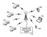
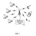
- FIG. 1illustrates a communication system for use with the invention
- FIG. 2illustrates the basic methodology of the invention in accordance with a preferred embodiment
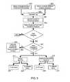
- FIG. 3illustrates a modification of the basic methodology shown in FIG. 2 ;
- FIG. 4provides a system level diagram of the primary systems utilized in at least one embodiment of the invention.
- a first calculationcould be termed a second calculation, and, similarly, a first step could be termed a second step, and, similarly, a first component could be termed a second component, without departing from the scope of this disclosure.
- the terms “electric vehicle” and “EV”may be used interchangeably and refer to an all-electric vehicle.
- an early warning central processing system 101is able to wirelessly communicate with a plurality of vehicles 103 , thus allowing central processing system 101 to identify conditions that routinely lead to a particular vehicle malfunction, or conditions that routinely cause a particular vehicle system to operate outside of its preferred operating range (i.e., out-of-spec). Once a set of conditions are identified, system 101 can send a notice to other vehicle owners, either via a user interface incorporated into each vehicle 103 or via an application installed on a user device 104 (e.g., smartphone, tablet, laptop, computer, etc.), thus helping other drivers avoid the same problem. It should be understood that warning system 101 may be operated by the vehicle's manufacturer, or a party working on behalf of the manufacturer, or a third party.
- FIG. 2illustrates the methodology associated with one embodiment of the invention.
- each vehicle 103monitors the performance of a preselected set of vehicle subsystems and components.
- the vehiclemay monitor battery pack performance, assuming that vehicle 103 is an EV, where performance is given in terms of state-of-charge (SOC), discharge rate, operating temperature, etc.
- SOCstate-of-charge
- the systemmay monitor engine oil pressure, coolant temperature, air flow through the intake, emissions, etc.
- ICEinternal combustion engine
- ambient conditionsrefer both to environmental conditions and operating conditions.
- the ambient temperatureis preferably monitored as are other environmental conditions (e.g., precipitation, humidity, atmospheric pressure, elevation, geographic location, etc.).
- various operating conditionsare preferably monitored (e.g., battery pack SOC, throttle position, vehicle speed, steering wheel position, motor or engine speed, HVAC settings, etc.).
- the operating performance of the various subsystems and components monitored in step 201 as well as the concurrent ambient conditions determined in step 203are recorded in a vehicle data log (step 205 ).
- the on-board vehicle controllermonitors for vehicle faults.
- a vehicle faultmay be as minor as one of the vehicle subsystems or components operating outside of its desired operating range, or as significant as a complete failure of the component or vehicle system.
- the systemcontinues to monitor vehicle performance and concurrent ambient conditions while generating a data log of both.
- the data logis automatically and wirelessly transmitted to central processing system 101 (step 213 ).
- the data logis transmitted during step 213 , for example the data log starting at a preset period of time before the fault was detected.
- the central processing system 101analyzes the fault as well as the ambient conditions both at the time of the fault and the conditions that preceded the fault (step 215 ).
- the central processing systemcorrelates the fault and the conditions surrounding the fault with similar faults detected in other vehicles 103 . If the detected fault is the only known occurrence under these or similar conditions, or if the detected fault has been observed in too few vehicles, then the central processing system 101 simply records the fault and the conditions surrounding the fault for possible correlation with future detected events (step 219 ). If, however, the central processing system 101 determines that the fault is not simply an isolated component or system failure, rather it is a fault that has been detected in other vehicles under similar circumstances, then the system sends out a notification to other users (step 221 ).
- the noticemay be sent to all users (step 223 ), warning each user that a certain type of fault may occur under a specific set of conditions, thus allowing each driver to modify their driving style or otherwise compensate for the conditions that may lead to the detected fault.
- the noticemay only be sent to those vehicles that are likely to experience the same fault based on the affected vehicle's current ambient conditions, e.g., current location, current elevation, ambient temperature, SOC, etc. (step 225 ).
- the controllermay also send out a possible solution (i.e., a work-around) to the detected fault (step 227 ).
- a possible solutioni.e., a work-around
- Exemplary solutionsinclude modifying the user's driving style (e.g., driving less aggressively), altering an EV's charging schedule, modifying HVAC settings, limiting power drain due to auxiliary systems, raising suspension height, etc.
- the notice and possible solutionmay be sent to all users (step 229 ) or only to those vehicles that are likely to experience the same fault based on the affected vehicle's current ambient conditions (step 231 ).
- notices (step 221 ) as well as the notices that include instructions (step 227 )may either be sent to the vehicles 103 using an on-board interface, or they may be sent to the users using an application installed on a user device 104 (e.g., smartphone, tablet, laptop, computer, etc.).
- a user device 104e.g., smartphone, tablet, laptop, computer, etc.
- the initial fault detectionis accomplished using an on-board control and monitoring system. It should be understood, however, that the invention can utilize other configurations as well.
- the on-board systemmonitors vehicle performance and ambient conditions, that data is either continuously or periodically sent to central processing system 101 (step 301 ) for analysis (step 303 ).
- the central processing system 101detects a fault in a vehicle component or subsystem (step 305 ), it correlates the fault and the conditions surrounding that fault with similar faults detected in other vehicles 103 (step 307 ).
- the central processing system 101simply records the fault and the conditions surrounding the fault for possible correlation with future detected events (step 219 ). If the central processing system 101 determines that the fault has been observed in a sufficient number of vehicles under similar conditions (step 311 ), then the system either transmits a warning to the users (step 221 ), or transmits a warning notification along with instructions to users, where the instructions explain how to either avoid the fault or mitigate its effects (step 227 ).
- the warning (step 221 ) and/or the warning plus instructions (step 227 )may either be sent to all users (steps 223 / 229 ) or only to those vehicles that are likely to experience the same fault based on the affected vehicle's current ambient conditions (steps 225 / 231 ).
- FIG. 4is a high-level view of an EV 400 and the primary systems that may be utilized by the present invention. It should be understood that although the system of the invention is illustrated with an EV, it is equally suited for use with a vehicle utilizing an internal combustion engine (ICE), or with a hybrid vehicle, where a hybrid vehicle utilizes multiple sources of propulsion including an electric drive system.
- ICEinternal combustion engine
- Vehicle 400includes a vehicle system controller 401 , also referred to as a vehicle management system, which is comprised of a central processing unit (CPU).
- System controller 401also includes memory 403 , with memory 403 being comprised of EPROM, EEPROM, flash memory, RAM, solid state drive, hard disk drive, or any other type of memory or combination of memory types.
- memory 403is used in at least one preferred configuration of the invention to store the log of vehicle performance, faults, and ambient conditions as described above.
- Interface 405allows the driver, or a passenger, to interact with the vehicle management system, for example inputting data into the navigation system, altering the heating, ventilation and air conditioning (HVAC) system, controlling the vehicle's entertainment system (e.g., radio, CD/DVD player, etc.), adjusting vehicle settings (e.g., seat positions, light controls, etc.), and/or otherwise altering the functionality of vehicle 400 .
- HVACheating, ventilation and air conditioning
- interface 405also includes means for the vehicle management system to provide information to the driver and/or passenger, information such as a navigation map or driving instructions as well as the operating performance of any of a variety of vehicle systems (e.g., battery pack charge level for an EV, fuel level for an ICE-based or hybrid vehicle, selected gear, current entertainment system settings such as volume level and selected track information, external light settings, current vehicle speed, current HVAC settings such as cabin temperature and/or fan settings, etc.).
- Interface 405may also be used to warn the driver of a vehicle condition (e.g., low battery charge level or low fuel level) and/or communicate an operating system malfunction (battery system not charging properly, low oil pressure for an ICE-based vehicle, low tire air pressure, etc.).
- interface 405is also used to receive fault warnings (e.g., step 221 ) and/or fault warnings combined with instructions (step 227 ).
- Interface 405may be comprised of a single interface, for example a touch-screen display, or a combination of user interfaces such as push-button switches, capacitive switches, slide or toggle switches, gauges, display screens, warning lights, audible warning signals, etc. It will be appreciated that if user interface 405 includes a graphical display, controller 401 may also include a graphical processing unit (GPU), with the GPU being either separate from or contained on the same chip set as the CPU.
- GPUgraphical processing unit
- Vehicle 400includes one or more motors 407 that provide vehicle propulsion, although as previously noted the invention is equally applicable to ICE-based or hybrid vehicles in which case motor(s) 407 would be replaced with an internal combustion engine or a hybrid drive train.
- the vehicle's drive systeme.g., motor 407
- the vehicle's drive systemmay be mechanically coupled to the front axle/wheels, the rear axle/wheels, or both, and may utilize any of a variety of transmission types (e.g., single speed, multi-speed) and differential types (e.g., open, locked, limited slip).
- the vehicleincludes a battery pack 409 , which may be comprised of one or hundreds or thousands of rechargeable batteries, that supplies the power necessary for operation of motor(s) 407 . Additionally, battery pack 409 may provide the power necessary for the various vehicle systems that require electrical power (e.g., lights, entertainment systems, navigation system, etc.). Typically battery pack 409 is coupled to motor(s) 407 via a power control system 411 that insures that the power delivered to the drive motor is of the proper form (e.g., correct voltage, current, waveform, etc.). Battery pack 409 is charged by charging system 413 , which may either be integrated into the vehicle as shown, or be comprised of an external charging system. Typically charging system 413 is configured to be electrically connected to an external power source, not shown, such as the municipal power grid. Battery pack 409 may also be charged, at least in part, using an on-board system such as a regenerative braking system.
- an on-board systemsuch as a regenerative braking system.
- Vehicle 400includes a thermal management system 415 that includes both a heating subsystem and a cooling subsystem.
- Thermal management system 415is coupled to the HVAC system controller 417 used to maintain the passenger cabin within the desired temperature range. Assuming vehicle 400 is an EV as shown, thermal management system 415 is also used to insure that the batteries within battery pack 409 are maintained within the desired operating, charging and/or storage temperature range.
- a communication link 419that is used to wirelessly transmit data (e.g., the data log containing component/subsystem performance, detected faults, ambient conditions, etc.) to central processing system 101 .
- central processing system 101may be located at the vehicle's manufacturer, a service center, a third party, etc.).
- Communication via link 419may use any of a variety of different technologies (e.g., GSM, EDGE, UMTS, CDMA, DECT, WiFi, WiMax, etc.).
- communication link 419along with interface 405 , is also used to receive fault warnings (e.g., step 221 ) and/or fault warnings combined with instructions (step 227 ) from central processing system 101 .
- sensors 421are also coupled to vehicle management system 401 and used to detect out-of-specification performance (e.g., faults) of various vehicle components and subsystems.
- sensors 421may include temperature sensors located in temperature sensitive regions of the vehicle (e.g., battery pack, motor, drive train, etc.), motor (or engine) speed sensors, battery pack performance sensors that may monitor various characteristics of the battery pack 409 (e.g., charge/discharge rates, SOC, etc.), as well as a variety of additional sensors if vehicle 400 is an ICE-based or hybrid vehicle (e.g., engine temperature, air flow through the air intake, oxygen concentration, emissions, oil pressure, etc.).
- Vehicle 400includes a variety of sensors that monitor ambient conditions, i.e., both environmental conditions and operating conditions, in addition to those sensors 421 that are used to monitor component and subsystem performance. As described above, by knowing the ambient conditions at the time that a fault, performance anomaly, or out-of-spec performance is detected, it is possible to determine the ambient conditions that may have affected a component or subsystem's performance, thereby allowing the problem to be avoided or its effects to be limited.
- vehicle 400includes a wide array of ambient condition sensors. For example, GPS and navigation system 423 allows the location of vehicle 400 to be known before, during and after a fault is detected.
- Vehicle performance as well as information as to how aggressively the vehicle is being drivenis preferably provided by both speed sensor 425 and accelerometer(s) 427 .
- a variety of ambient environmental sensors 429monitor external conditions. Sensors 429 may include temperature sensor(s), humidity sensor(s), precipitation sensor(s), elevation sensor(s), etc.
- Various auxiliary systems 431e.g., a vehicle suspension system may also be coupled to, and monitored by, vehicle management system 401 , thereby providing additional information about the vehicle's performance during normal use as well as when a fault is detected.
Landscapes
- Physics & Mathematics (AREA)
- General Physics & Mathematics (AREA)
- Electric Propulsion And Braking For Vehicles (AREA)
Abstract
Description
Claims (11)
Priority Applications (2)
| Application Number | Priority Date | Filing Date | Title |
|---|---|---|---|
| US14/309,238US9495814B2 (en) | 2014-06-19 | 2014-06-19 | Vehicle fault early warning system |
| US15/286,409US9626811B2 (en) | 2014-06-19 | 2016-10-05 | Vehicle fault early warning system |
Applications Claiming Priority (1)
| Application Number | Priority Date | Filing Date | Title |
|---|---|---|---|
| US14/309,238US9495814B2 (en) | 2014-06-19 | 2014-06-19 | Vehicle fault early warning system |
Related Child Applications (1)
| Application Number | Title | Priority Date | Filing Date |
|---|---|---|---|
| US15/286,409Continuation-In-PartUS9626811B2 (en) | 2014-06-19 | 2016-10-05 | Vehicle fault early warning system |
Publications (2)
| Publication Number | Publication Date |
|---|---|
| US20150371462A1 US20150371462A1 (en) | 2015-12-24 |
| US9495814B2true US9495814B2 (en) | 2016-11-15 |
Family
ID=54870140
Family Applications (1)
| Application Number | Title | Priority Date | Filing Date |
|---|---|---|---|
| US14/309,238Active2034-11-14US9495814B2 (en) | 2014-06-19 | 2014-06-19 | Vehicle fault early warning system |
Country Status (1)
| Country | Link |
|---|---|
| US (1) | US9495814B2 (en) |
Cited By (28)
| Publication number | Priority date | Publication date | Assignee | Title |
|---|---|---|---|---|
| US20160012650A1 (en)* | 2014-07-08 | 2016-01-14 | Navico Holding As | Marine Data Collection |
| US20160375782A1 (en)* | 2015-06-23 | 2016-12-29 | Atieva, Inc. | Electric Vehicle Driving Range Optimization System with Dynamic Feedback |
| US9626811B2 (en)* | 2014-06-19 | 2017-04-18 | Atieva, Inc. | Vehicle fault early warning system |
| US20180312073A1 (en)* | 2017-04-26 | 2018-11-01 | Hyundai Motor Corporation | Apparatus for controlling battery state of charge, system having apparatus for controlling battery state of charge, and method for controlling battery state of charge |
| US10742155B2 (en) | 2018-03-19 | 2020-08-11 | Tula eTechnology, Inc. | Pulsed electric machine control |
| US10944352B2 (en) | 2018-03-19 | 2021-03-09 | Tula eTechnology, Inc. | Boosted converter for pulsed electric machine control |
| US11007846B2 (en) | 2018-04-05 | 2021-05-18 | Ford Global Technologies, Llc | Auto-isolate vehicular climate system |
| US11133767B2 (en) | 2018-03-19 | 2021-09-28 | Tula eTechnology, Inc. | Pulsed electric machine control using tables |
| US11427177B2 (en) | 2019-11-20 | 2022-08-30 | Tula eTechnology, Inc. | Pulsed electric machine control using tables |
| US11557996B1 (en) | 2021-07-08 | 2023-01-17 | Tula eTechnology, Inc. | Methods of reducing vibrations for electric motors |
| US11623529B2 (en) | 2018-03-19 | 2023-04-11 | Tula eTechnology, Inc. | Pulse modulated control with field weakening for improved motor efficiency |
| US11628730B2 (en) | 2021-01-26 | 2023-04-18 | Tula eTechnology, Inc. | Pulsed electric machine control |
| US11637466B1 (en) | 2021-10-18 | 2023-04-25 | Tula Etechnology Inc. | Mechanical and electromechanical arrangements for field-weakening of an electric machine that utilizes permanent magnets |
| US11637513B2 (en) | 2021-03-15 | 2023-04-25 | Tula eTechnology, Inc. | Methods of optimizing waveforms for electric motors |
| US11673476B2 (en) | 2021-08-12 | 2023-06-13 | Tula eTechnology, Inc. | Method of optimizing system efficiency for battery powered electric motors |
| US11695361B2 (en) | 2021-06-14 | 2023-07-04 | Tula eTechnology, Inc. | Electric machines with efficient torque transitions |
| US11704590B2 (en) | 2017-03-24 | 2023-07-18 | Toyota Motor Engineering & Manufacturing North America, Inc. | Methods and systems for predicting failure of a power control unit of a vehicle |
| US11888424B1 (en) | 2022-07-18 | 2024-01-30 | Tula eTechnology, Inc. | Methods for improving rate of rise of torque in electric machines with stator current biasing |
| US11916498B2 (en) | 2021-09-08 | 2024-02-27 | Tule eTechnology Inc. | Electric machine torque adjustment based on waveform integer multiples |
| US11973447B2 (en) | 2021-06-28 | 2024-04-30 | Tula eTechnology, Inc. | Selective phase control of an electric machine |
| US12244250B2 (en) | 2022-07-18 | 2025-03-04 | Tula eTechnology, Inc. | Feedback scaling for electric machines |
| US12278581B2 (en) | 2022-03-22 | 2025-04-15 | Tula eTechnology, Inc. | Delay reduction for pulsed wound field synchronous machines |
| US12301151B2 (en) | 2022-08-22 | 2025-05-13 | Tula eTechnology, Inc. | Boosted rotor supply circuit and method for improving pulsed electric machine efficiency |
| US12311772B2 (en) | 2018-03-19 | 2025-05-27 | Tula eTechnology, Inc. | Pulse modulated control with field weakening for improved machine efficiency |
| US12319147B2 (en) | 2021-01-26 | 2025-06-03 | Tula eTechnology, Inc. | Pulsed electric machine control |
| US12328088B2 (en) | 2021-10-11 | 2025-06-10 | Tula eTechnology, Inc. | Pulsed control of multiple electric machines |
| US12370907B2 (en) | 2023-10-17 | 2025-07-29 | Tula eTechnology, Inc. | On-pulse transition times for pulsed controlled electric machines using boost voltages |
| US12424962B2 (en) | 2022-07-18 | 2025-09-23 | Tula eTechnology, Inc. | Pulsed electric machine control with soft start and end |
Families Citing this family (18)
| Publication number | Priority date | Publication date | Assignee | Title |
|---|---|---|---|---|
| US9201842B2 (en) | 2006-03-16 | 2015-12-01 | Smartdrive Systems, Inc. | Vehicle event recorder systems and networks having integrated cellular wireless communications systems |
| US8996240B2 (en) | 2006-03-16 | 2015-03-31 | Smartdrive Systems, Inc. | Vehicle event recorders with integrated web server |
| US8649933B2 (en) | 2006-11-07 | 2014-02-11 | Smartdrive Systems Inc. | Power management systems for automotive video event recorders |
| US8989959B2 (en) | 2006-11-07 | 2015-03-24 | Smartdrive Systems, Inc. | Vehicle operator performance history recording, scoring and reporting systems |
| US8868288B2 (en) | 2006-11-09 | 2014-10-21 | Smartdrive Systems, Inc. | Vehicle exception event management systems |
| US8239092B2 (en) | 2007-05-08 | 2012-08-07 | Smartdrive Systems Inc. | Distributed vehicle event recorder systems having a portable memory data transfer system |
| US9501878B2 (en) | 2013-10-16 | 2016-11-22 | Smartdrive Systems, Inc. | Vehicle event playback apparatus and methods |
| US9610955B2 (en) | 2013-11-11 | 2017-04-04 | Smartdrive Systems, Inc. | Vehicle fuel consumption monitor and feedback systems |
| US9677529B2 (en)* | 2013-12-25 | 2017-06-13 | Denso Corporation | Vehicle diagnosis system and method |
| US8892310B1 (en) | 2014-02-21 | 2014-11-18 | Smartdrive Systems, Inc. | System and method to detect execution of driving maneuvers |
| US9663127B2 (en) | 2014-10-28 | 2017-05-30 | Smartdrive Systems, Inc. | Rail vehicle event detection and recording system |
| US9902410B2 (en) | 2015-01-08 | 2018-02-27 | Smartdrive Systems, Inc. | System and method for synthesizing rail vehicle event information |
| US9487222B2 (en)* | 2015-01-08 | 2016-11-08 | Smartdrive Systems, Inc. | System and method for aggregation display and analysis of rail vehicle event information |
| US9296401B1 (en) | 2015-01-12 | 2016-03-29 | Smartdrive Systems, Inc. | Rail vehicle event triggering system and method |
| US9679420B2 (en) | 2015-04-01 | 2017-06-13 | Smartdrive Systems, Inc. | Vehicle event recording system and method |
| US9843877B2 (en) | 2015-12-31 | 2017-12-12 | Ebay Inc. | Sound recognition |
| US20170200325A1 (en)* | 2016-01-13 | 2017-07-13 | Ford Global Technologies, Llc | Diagnostic test performance control system and method |
| US10378486B2 (en)* | 2017-08-07 | 2019-08-13 | Ford Global Technologies, Llc | Systems and methods for diagnosing a vehicle fuel system and evaporative emissions control system |
Citations (37)
| Publication number | Priority date | Publication date | Assignee | Title |
|---|---|---|---|---|
| US4345199A (en)* | 1979-06-18 | 1982-08-17 | General Motors Corporation | Generator voltage regulator |
| US5699056A (en)* | 1994-12-28 | 1997-12-16 | Omron Corporation | Traffic information system |
| US5737215A (en)* | 1995-12-13 | 1998-04-07 | Caterpillar Inc. | Method and apparatus for comparing machines in fleet |
| US20020038182A1 (en)* | 2000-06-06 | 2002-03-28 | Wong Carlos C.H. | Wireless vehicle monitoring system |
| US20020067289A1 (en)* | 2000-12-05 | 2002-06-06 | Michael Smith | Vehicle-centric weather prediction system and method |
| US20020156558A1 (en)* | 2001-03-16 | 2002-10-24 | Hanson Richard E. | Method and apparatus for monitoring work vehicles |
| US20030065771A1 (en)* | 2001-09-28 | 2003-04-03 | Regine Cramer | Method for creating a maintenance algorithm |
| US20040138790A1 (en)* | 2000-08-18 | 2004-07-15 | Michael Kapolka | Remote monitoring, configuring, programming and diagnostic system and method for vehicles and vehicle components |
| US6792351B2 (en)* | 2001-06-26 | 2004-09-14 | Medius, Inc. | Method and apparatus for multi-vehicle communication |
| US20040267446A1 (en)* | 2003-04-18 | 2004-12-30 | Junji Minato | Navigation apparatus and access method to map data therein |
| US20050065678A1 (en)* | 2000-08-18 | 2005-03-24 | Snap-On Technologies, Inc. | Enterprise resource planning system with integrated vehicle diagnostic and information system |
| US20050065711A1 (en)* | 2003-04-07 | 2005-03-24 | Darwin Dahlgren | Centralized facility and intelligent on-board vehicle platform for collecting, analyzing and distributing information relating to transportation infrastructure and conditions |
| US7123926B2 (en)* | 1999-09-10 | 2006-10-17 | Himmelstein Richard B | System and method for providing information to users based on the user's location |
| US7174253B2 (en)* | 2002-07-09 | 2007-02-06 | General Motors Corporation | Receiving traffic update information and reroute information in a mobile vehicle |
| US20070083305A1 (en)* | 2005-10-11 | 2007-04-12 | Denso Corporation | Vehicle abnormality monitoring apparatus |
| US20070265742A1 (en)* | 2006-05-08 | 2007-11-15 | Christof Thiel | Method for the diagnosis of, and control device for controlling a motor vehicle |
| JP2008121916A (en)* | 2006-11-08 | 2008-05-29 | Denso Corp | Air conditioning system for vehicle |
| US7425903B2 (en)* | 2006-04-28 | 2008-09-16 | International Business Machines Corporation | Dynamic vehicle grid infrastructure to allow vehicles to sense and respond to traffic conditions |
| US20090254259A1 (en)* | 2008-04-08 | 2009-10-08 | The Jacob K | Third Party Speed Control Device |
| US20100057290A1 (en)* | 2008-09-02 | 2010-03-04 | International Business Machines Corporation | System and method for cooperative vehicle diagnostics |
| US20100211249A1 (en)* | 2009-02-13 | 2010-08-19 | Mcclellan Scott | System and method for detecting vehicle maintenance requirements |
| US7849149B2 (en)* | 2004-04-06 | 2010-12-07 | Honda Motor Co., Ltd. | Method and system for controlling the exchange of vehicle related messages |
| US20110130905A1 (en)* | 2009-12-01 | 2011-06-02 | Ise Corporation | Remote Vehicle Monitoring and Diagnostic System and Method |
| US20110160934A1 (en)* | 2009-12-25 | 2011-06-30 | Denso Corporation | On-vehicle fault detecting device |
| US20110276313A1 (en)* | 2010-05-10 | 2011-11-10 | Denso Corporation | Recording system, in-vehicle apparatus, and portable terminal |
| US20120235805A1 (en)* | 2009-12-10 | 2012-09-20 | Panasonic Corporation | Information display apparatus and information display method |
| US8296197B2 (en)* | 2005-11-16 | 2012-10-23 | The Boeing Company | Centralized management of maintenance and materials for commercial aircraft fleets with information feedback to customer |
| US20130246135A1 (en)* | 2012-03-14 | 2013-09-19 | Zhenrong Wang | System, device and method of remote vehicle diagnostics based service for vehicle owners |
| US20130282921A1 (en)* | 2012-04-24 | 2013-10-24 | Honeywell International Inc. | Dynamic threading gateway for embedded health management systems |
| US8634033B2 (en)* | 2006-12-20 | 2014-01-21 | Johnson Controls Technology Company | Remote display reproduction system and method |
| US20140168827A1 (en)* | 2012-12-18 | 2014-06-19 | Caterpillar Global Mining Llc | Motor protection system |
| US8952800B2 (en)* | 2011-01-11 | 2015-02-10 | International Business Machines Corporation | Prevention of texting while operating a motor vehicle |
| US20150127228A1 (en)* | 2013-10-30 | 2015-05-07 | Powervoice Co., Ltd. | Sound qr system for vehicular services |
| US20150137962A1 (en)* | 2013-10-25 | 2015-05-21 | Gary Binnicker | Temperature-Sensitive Vehicle Occupancy Detection and Alert System |
| US20150307086A1 (en)* | 2012-11-26 | 2015-10-29 | Renault S.A.S. | Method and system for controlling a hybrid vehicle with independent rear electric motors |
| US20150344070A1 (en)* | 2014-05-09 | 2015-12-03 | Kyungpook National University Industry-Academic Cooperation Foundation | Apparatus and method for fault tolerant trajectory generation a left-right independent active front steering vehicle |
| US20150356794A1 (en)* | 2014-06-05 | 2015-12-10 | Ford Global Technologies, Llc | Connected vehicle predictive quality |
- 2014
- 2014-06-19USUS14/309,238patent/US9495814B2/enactiveActive
Patent Citations (38)
| Publication number | Priority date | Publication date | Assignee | Title |
|---|---|---|---|---|
| US4345199A (en)* | 1979-06-18 | 1982-08-17 | General Motors Corporation | Generator voltage regulator |
| US5699056A (en)* | 1994-12-28 | 1997-12-16 | Omron Corporation | Traffic information system |
| US5737215A (en)* | 1995-12-13 | 1998-04-07 | Caterpillar Inc. | Method and apparatus for comparing machines in fleet |
| US7123926B2 (en)* | 1999-09-10 | 2006-10-17 | Himmelstein Richard B | System and method for providing information to users based on the user's location |
| US20020038182A1 (en)* | 2000-06-06 | 2002-03-28 | Wong Carlos C.H. | Wireless vehicle monitoring system |
| US20050065678A1 (en)* | 2000-08-18 | 2005-03-24 | Snap-On Technologies, Inc. | Enterprise resource planning system with integrated vehicle diagnostic and information system |
| US20040138790A1 (en)* | 2000-08-18 | 2004-07-15 | Michael Kapolka | Remote monitoring, configuring, programming and diagnostic system and method for vehicles and vehicle components |
| US20020067289A1 (en)* | 2000-12-05 | 2002-06-06 | Michael Smith | Vehicle-centric weather prediction system and method |
| US20020156558A1 (en)* | 2001-03-16 | 2002-10-24 | Hanson Richard E. | Method and apparatus for monitoring work vehicles |
| US6792351B2 (en)* | 2001-06-26 | 2004-09-14 | Medius, Inc. | Method and apparatus for multi-vehicle communication |
| US20030065771A1 (en)* | 2001-09-28 | 2003-04-03 | Regine Cramer | Method for creating a maintenance algorithm |
| US7174253B2 (en)* | 2002-07-09 | 2007-02-06 | General Motors Corporation | Receiving traffic update information and reroute information in a mobile vehicle |
| US20050065711A1 (en)* | 2003-04-07 | 2005-03-24 | Darwin Dahlgren | Centralized facility and intelligent on-board vehicle platform for collecting, analyzing and distributing information relating to transportation infrastructure and conditions |
| US20040267446A1 (en)* | 2003-04-18 | 2004-12-30 | Junji Minato | Navigation apparatus and access method to map data therein |
| US7849149B2 (en)* | 2004-04-06 | 2010-12-07 | Honda Motor Co., Ltd. | Method and system for controlling the exchange of vehicle related messages |
| US20070083305A1 (en)* | 2005-10-11 | 2007-04-12 | Denso Corporation | Vehicle abnormality monitoring apparatus |
| US8296197B2 (en)* | 2005-11-16 | 2012-10-23 | The Boeing Company | Centralized management of maintenance and materials for commercial aircraft fleets with information feedback to customer |
| US7425903B2 (en)* | 2006-04-28 | 2008-09-16 | International Business Machines Corporation | Dynamic vehicle grid infrastructure to allow vehicles to sense and respond to traffic conditions |
| US20070265742A1 (en)* | 2006-05-08 | 2007-11-15 | Christof Thiel | Method for the diagnosis of, and control device for controlling a motor vehicle |
| JP2008121916A (en)* | 2006-11-08 | 2008-05-29 | Denso Corp | Air conditioning system for vehicle |
| US8634033B2 (en)* | 2006-12-20 | 2014-01-21 | Johnson Controls Technology Company | Remote display reproduction system and method |
| US20090254259A1 (en)* | 2008-04-08 | 2009-10-08 | The Jacob K | Third Party Speed Control Device |
| US20100057290A1 (en)* | 2008-09-02 | 2010-03-04 | International Business Machines Corporation | System and method for cooperative vehicle diagnostics |
| US20100211249A1 (en)* | 2009-02-13 | 2010-08-19 | Mcclellan Scott | System and method for detecting vehicle maintenance requirements |
| US20110130905A1 (en)* | 2009-12-01 | 2011-06-02 | Ise Corporation | Remote Vehicle Monitoring and Diagnostic System and Method |
| US20120235805A1 (en)* | 2009-12-10 | 2012-09-20 | Panasonic Corporation | Information display apparatus and information display method |
| US20110160934A1 (en)* | 2009-12-25 | 2011-06-30 | Denso Corporation | On-vehicle fault detecting device |
| US20110276313A1 (en)* | 2010-05-10 | 2011-11-10 | Denso Corporation | Recording system, in-vehicle apparatus, and portable terminal |
| US8952800B2 (en)* | 2011-01-11 | 2015-02-10 | International Business Machines Corporation | Prevention of texting while operating a motor vehicle |
| US20130246135A1 (en)* | 2012-03-14 | 2013-09-19 | Zhenrong Wang | System, device and method of remote vehicle diagnostics based service for vehicle owners |
| US20130282921A1 (en)* | 2012-04-24 | 2013-10-24 | Honeywell International Inc. | Dynamic threading gateway for embedded health management systems |
| US20150307086A1 (en)* | 2012-11-26 | 2015-10-29 | Renault S.A.S. | Method and system for controlling a hybrid vehicle with independent rear electric motors |
| US20140168827A1 (en)* | 2012-12-18 | 2014-06-19 | Caterpillar Global Mining Llc | Motor protection system |
| US20150137962A1 (en)* | 2013-10-25 | 2015-05-21 | Gary Binnicker | Temperature-Sensitive Vehicle Occupancy Detection and Alert System |
| US20150127228A1 (en)* | 2013-10-30 | 2015-05-07 | Powervoice Co., Ltd. | Sound qr system for vehicular services |
| US20150344070A1 (en)* | 2014-05-09 | 2015-12-03 | Kyungpook National University Industry-Academic Cooperation Foundation | Apparatus and method for fault tolerant trajectory generation a left-right independent active front steering vehicle |
| US9387882B2 (en)* | 2014-05-09 | 2016-07-12 | Kyungpook National University Industry-Academic Cooperation Foundation | Apparatus and method for fault tolerant trajectory generation a left-right independent active front steering vehicle |
| US20150356794A1 (en)* | 2014-06-05 | 2015-12-10 | Ford Global Technologies, Llc | Connected vehicle predictive quality |
Cited By (37)
| Publication number | Priority date | Publication date | Assignee | Title |
|---|---|---|---|---|
| US9626811B2 (en)* | 2014-06-19 | 2017-04-18 | Atieva, Inc. | Vehicle fault early warning system |
| US20160012650A1 (en)* | 2014-07-08 | 2016-01-14 | Navico Holding As | Marine Data Collection |
| US20160375782A1 (en)* | 2015-06-23 | 2016-12-29 | Atieva, Inc. | Electric Vehicle Driving Range Optimization System with Dynamic Feedback |
| US11704590B2 (en) | 2017-03-24 | 2023-07-18 | Toyota Motor Engineering & Manufacturing North America, Inc. | Methods and systems for predicting failure of a power control unit of a vehicle |
| US20180312073A1 (en)* | 2017-04-26 | 2018-11-01 | Hyundai Motor Corporation | Apparatus for controlling battery state of charge, system having apparatus for controlling battery state of charge, and method for controlling battery state of charge |
| US10688869B2 (en)* | 2017-04-26 | 2020-06-23 | Hyundai Motor Company | Apparatus for controlling battery state of charge, system having apparatus for controlling battery state of charge, and method for controlling battery state of charge |
| US12311772B2 (en) | 2018-03-19 | 2025-05-27 | Tula eTechnology, Inc. | Pulse modulated control with field weakening for improved machine efficiency |
| US12301149B2 (en) | 2018-03-19 | 2025-05-13 | Tula eTechnology, Inc. | Pulsed electric machine control |
| US11133767B2 (en) | 2018-03-19 | 2021-09-28 | Tula eTechnology, Inc. | Pulsed electric machine control using tables |
| US11228272B2 (en) | 2018-03-19 | 2022-01-18 | Tula eTechnology, Inc. | Pulsed electric machine control |
| US11863096B2 (en) | 2018-03-19 | 2024-01-02 | Tula eTechnology, Inc. | Boosted converter for pulsed electric machine control |
| US11623529B2 (en) | 2018-03-19 | 2023-04-11 | Tula eTechnology, Inc. | Pulse modulated control with field weakening for improved motor efficiency |
| US11626827B2 (en) | 2018-03-19 | 2023-04-11 | Tula eTechnology, Inc. | Pulsed electric machine control |
| US10742155B2 (en) | 2018-03-19 | 2020-08-11 | Tula eTechnology, Inc. | Pulsed electric machine control |
| US12003202B2 (en) | 2018-03-19 | 2024-06-04 | Tula eTechnology, Inc. | Pulsed electric machine control |
| US10944352B2 (en) | 2018-03-19 | 2021-03-09 | Tula eTechnology, Inc. | Boosted converter for pulsed electric machine control |
| US11007846B2 (en) | 2018-04-05 | 2021-05-18 | Ford Global Technologies, Llc | Auto-isolate vehicular climate system |
| US11427177B2 (en) | 2019-11-20 | 2022-08-30 | Tula eTechnology, Inc. | Pulsed electric machine control using tables |
| US11628730B2 (en) | 2021-01-26 | 2023-04-18 | Tula eTechnology, Inc. | Pulsed electric machine control |
| US12319147B2 (en) | 2021-01-26 | 2025-06-03 | Tula eTechnology, Inc. | Pulsed electric machine control |
| US11637513B2 (en) | 2021-03-15 | 2023-04-25 | Tula eTechnology, Inc. | Methods of optimizing waveforms for electric motors |
| US11695361B2 (en) | 2021-06-14 | 2023-07-04 | Tula eTechnology, Inc. | Electric machines with efficient torque transitions |
| US12206346B2 (en) | 2021-06-14 | 2025-01-21 | Tula eTechnology, Inc. | Electric machines with efficient torque transitions |
| US11973447B2 (en) | 2021-06-28 | 2024-04-30 | Tula eTechnology, Inc. | Selective phase control of an electric machine |
| US12199532B2 (en) | 2021-07-08 | 2025-01-14 | Tula eTechnology, Inc. | Methods of reducing vibrations for electric motors |
| US11557996B1 (en) | 2021-07-08 | 2023-01-17 | Tula eTechnology, Inc. | Methods of reducing vibrations for electric motors |
| US12145452B2 (en) | 2021-08-12 | 2024-11-19 | Tula eTechnology, Inc. | Method of optimizing system efficiency for battery powered electric motors |
| US11673476B2 (en) | 2021-08-12 | 2023-06-13 | Tula eTechnology, Inc. | Method of optimizing system efficiency for battery powered electric motors |
| US11916498B2 (en) | 2021-09-08 | 2024-02-27 | Tule eTechnology Inc. | Electric machine torque adjustment based on waveform integer multiples |
| US12328088B2 (en) | 2021-10-11 | 2025-06-10 | Tula eTechnology, Inc. | Pulsed control of multiple electric machines |
| US11637466B1 (en) | 2021-10-18 | 2023-04-25 | Tula Etechnology Inc. | Mechanical and electromechanical arrangements for field-weakening of an electric machine that utilizes permanent magnets |
| US12278581B2 (en) | 2022-03-22 | 2025-04-15 | Tula eTechnology, Inc. | Delay reduction for pulsed wound field synchronous machines |
| US12244250B2 (en) | 2022-07-18 | 2025-03-04 | Tula eTechnology, Inc. | Feedback scaling for electric machines |
| US11888424B1 (en) | 2022-07-18 | 2024-01-30 | Tula eTechnology, Inc. | Methods for improving rate of rise of torque in electric machines with stator current biasing |
| US12424962B2 (en) | 2022-07-18 | 2025-09-23 | Tula eTechnology, Inc. | Pulsed electric machine control with soft start and end |
| US12301151B2 (en) | 2022-08-22 | 2025-05-13 | Tula eTechnology, Inc. | Boosted rotor supply circuit and method for improving pulsed electric machine efficiency |
| US12370907B2 (en) | 2023-10-17 | 2025-07-29 | Tula eTechnology, Inc. | On-pulse transition times for pulsed controlled electric machines using boost voltages |
Also Published As
| Publication number | Publication date |
|---|---|
| US20150371462A1 (en) | 2015-12-24 |
Similar Documents
| Publication | Publication Date | Title |
|---|---|---|
| US9495814B2 (en) | Vehicle fault early warning system | |
| US9626811B2 (en) | Vehicle fault early warning system | |
| US20200043254A1 (en) | Data storage device of vehicle | |
| CN109910781B (en) | System and method for monitoring a vehicle power system | |
| JP6186653B2 (en) | Method for providing a constant mileage in an electric vehicle | |
| CN108725203B (en) | System and method for maintaining high voltage battery charge in the event of detection of auxiliary battery failure | |
| EP3025900B1 (en) | Battery pack charging protocol selection system | |
| US9517703B1 (en) | Electric vehicle driving range optimization system with dynamic feedback | |
| US9919666B2 (en) | Method for diagnosing leakage of electric parts and servicing guide of driving state for vehicle in battery management system | |
| US9623765B2 (en) | Electric vehicle driving range optimization system with dynamic feedback | |
| US9221409B1 (en) | Vehicle power distribution system | |
| US9293795B2 (en) | Apparatus and method for controlling cooling of battery of environment-friendly vehicle | |
| US20160375785A1 (en) | Electric Vehicle Dynamic Feedback System | |
| US9725011B2 (en) | System and method for controlling emergency driving for fuel cell vehicle | |
| US9248756B2 (en) | Plug-in vehicle eco charging mode | |
| US9517705B1 (en) | Electric vehicle driving range optimization system with dynamic feedback | |
| US20160107525A1 (en) | Method for reconnecting a relay in a vehicle battery management system | |
| US10471839B2 (en) | Method and system for detecting fusion of relay | |
| US20160375782A1 (en) | Electric Vehicle Driving Range Optimization System with Dynamic Feedback | |
| US12099393B2 (en) | Power management apparatus and vehicle having the same | |
| CN113844395A (en) | Vehicle load grading offload | |
| CN102947136B (en) | Aging degree judging device | |
| CN101879865A (en) | Vehicle breakdown treatment system | |
| US9463700B2 (en) | Method of selecting a battery pack charging protocol | |
| US9227581B1 (en) | Vehicle power distribution system with extended storage capabilities |
Legal Events
| Date | Code | Title | Description |
|---|---|---|---|
| AS | Assignment | Owner name:ATIEVA, INC., CALIFORNIA Free format text:ASSIGNMENT OF ASSIGNORS INTEREST;ASSIGNOR:RAMESH, VINEETH;REEL/FRAME:033140/0843 Effective date:20140619 | |
| FEPP | Fee payment procedure | Free format text:PAYOR NUMBER ASSIGNED (ORIGINAL EVENT CODE: ASPN); ENTITY STATUS OF PATENT OWNER: LARGE ENTITY | |
| STCF | Information on status: patent grant | Free format text:PATENTED CASE | |
| AS | Assignment | Owner name:TRINITY CAPITAL FUND III, L. P., ARIZONA Free format text:INTELLECTUAL PROPERTY SECURITY AGREEMENT;ASSIGNOR:ATIEVA, INC;REEL/FRAME:042125/0897 Effective date:20170331 | |
| AS | Assignment | Owner name:YINLONG ELECTRIC VEHICLE (HK) GROUP LIMITED, HONG KONG Free format text:SECURITY INTEREST;ASSIGNORS:ATIEVA, INC.;ATIEVA USA, INC;REEL/FRAME:044457/0942 Effective date:20171027 Owner name:YINLONG ELECTRIC VEHICLE (HK) GROUP LIMITED, HONG Free format text:SECURITY INTEREST;ASSIGNORS:ATIEVA, INC.;ATIEVA USA, INC;REEL/FRAME:044457/0942 Effective date:20171027 | |
| AS | Assignment | Owner name:AVB METRICS, LLC, CALIFORNIA Free format text:RELEASE BY SECURED PARTY;ASSIGNOR:TRINITY CAPITAL FUND III, L.P.;REEL/FRAME:047529/0619 Effective date:20180912 Owner name:ATIEVA, INC., CAYMAN ISLANDS Free format text:RELEASE BY SECURED PARTY;ASSIGNOR:TRINITY CAPITAL FUND III, L.P.;REEL/FRAME:047529/0619 Effective date:20180912 Owner name:ATIEVA USA, INC., CALIFORNIA Free format text:RELEASE BY SECURED PARTY;ASSIGNOR:TRINITY CAPITAL FUND III, L.P.;REEL/FRAME:047529/0619 Effective date:20180912 | |
| AS | Assignment | Owner name:ATIEVA USA, INC., CALIFORNIA Free format text:RELEASE BY SECURED PARTY;ASSIGNOR:YINLONG ELECTRIC VEHICLE (HK) GROUP LIMITED;REEL/FRAME:047620/0451 Effective date:20180914 Owner name:ATIEVA, INC., CAYMAN ISLANDS Free format text:RELEASE BY SECURED PARTY;ASSIGNOR:YINLONG ELECTRIC VEHICLE (HK) GROUP LIMITED;REEL/FRAME:047620/0451 Effective date:20180914 Owner name:AVB METRICS, LLC, CALIFORNIA Free format text:RELEASE BY SECURED PARTY;ASSIGNOR:YINLONG ELECTRIC VEHICLE (HK) GROUP LIMITED;REEL/FRAME:047620/0451 Effective date:20180914 | |
| AS | Assignment | Owner name:AYAR THIRD INVESTMENT COMPANY, SAUDI ARABIA Free format text:SECURITY INTEREST;ASSIGNOR:ATIEVA, INC.;REEL/FRAME:047199/0221 Effective date:20180916 | |
| AS | Assignment | Owner name:ATIEVA, INC., CALIFORNIA Free format text:RELEASE BY SECURED PARTY;ASSIGNOR:AYAR THIRD INVESTMENT COMPANY;REEL/FRAME:048811/0472 Effective date:20190402 | |
| MAFP | Maintenance fee payment | Free format text:PAYMENT OF MAINTENANCE FEE, 4TH YEAR, LARGE ENTITY (ORIGINAL EVENT CODE: M1551); ENTITY STATUS OF PATENT OWNER: LARGE ENTITY Year of fee payment:4 | |
| FEPP | Fee payment procedure | Free format text:ENTITY STATUS SET TO UNDISCOUNTED (ORIGINAL EVENT CODE: BIG.); ENTITY STATUS OF PATENT OWNER: LARGE ENTITY | |
| MAFP | Maintenance fee payment | Free format text:PAYMENT OF MAINTENANCE FEE, 8TH YEAR, LARGE ENTITY (ORIGINAL EVENT CODE: M1552); ENTITY STATUS OF PATENT OWNER: LARGE ENTITY Year of fee payment:8 |