US9494249B2 - Mechanical stop for actuator and orifice - Google Patents
Mechanical stop for actuator and orificeDownload PDFInfo
- Publication number
- US9494249B2 US9494249B2US14/273,823US201414273823AUS9494249B2US 9494249 B2US9494249 B2US 9494249B2US 201414273823 AUS201414273823 AUS 201414273823AUS 9494249 B2US9494249 B2US 9494249B2
- Authority
- US
- United States
- Prior art keywords
- solenoid
- valve
- mechanical stop
- valve cover
- actuator
- Prior art date
- Legal status (The legal status is an assumption and is not a legal conclusion. Google has not performed a legal analysis and makes no representation as to the accuracy of the status listed.)
- Active, expires
Links
- XLYOFNOQVPJJNP-UHFFFAOYSA-NwaterSubstancesOXLYOFNOQVPJJNP-UHFFFAOYSA-N0.000claimsdescription113
- 238000004891communicationMethods0.000claimsdescription19
- 238000000034methodMethods0.000claimsdescription16
- 108091006146ChannelsProteins0.000description43
- 230000006870functionEffects0.000description9
- 230000000007visual effectEffects0.000description8
- 230000037361pathwayEffects0.000description6
- 230000008859changeEffects0.000description4
- 239000000463materialSubstances0.000description4
- CWYNVVGOOAEACU-UHFFFAOYSA-NFe2+Chemical compound[Fe+2]CWYNVVGOOAEACU-UHFFFAOYSA-N0.000description3
- 230000008901benefitEffects0.000description3
- 239000012530fluidSubstances0.000description3
- 238000003466weldingMethods0.000description3
- 238000009412basement excavationMethods0.000description2
- 238000006073displacement reactionMethods0.000description2
- 229920001971elastomerPolymers0.000description2
- 230000003993interactionEffects0.000description2
- WABPQHHGFIMREM-UHFFFAOYSA-Nlead(0)Chemical compound[Pb]WABPQHHGFIMREM-UHFFFAOYSA-N0.000description2
- 238000005259measurementMethods0.000description2
- 230000004048modificationEffects0.000description2
- 238000012986modificationMethods0.000description2
- 239000004033plasticSubstances0.000description2
- 230000008569processEffects0.000description2
- 238000007789sealingMethods0.000description2
- 238000011144upstream manufacturingMethods0.000description2
- 229910001369BrassInorganic materials0.000description1
- 229910000906BronzeInorganic materials0.000description1
- 229920002943EPDM rubberPolymers0.000description1
- 229910000831SteelInorganic materials0.000description1
- 230000009471actionEffects0.000description1
- XAGFODPZIPBFFR-UHFFFAOYSA-NaluminiumChemical compound[Al]XAGFODPZIPBFFR-UHFFFAOYSA-N0.000description1
- 229910052782aluminiumInorganic materials0.000description1
- 230000000712assemblyEffects0.000description1
- 238000000429assemblyMethods0.000description1
- 239000010951brassSubstances0.000description1
- 239000010974bronzeSubstances0.000description1
- 238000010276constructionMethods0.000description1
- KUNSUQLRTQLHQQ-UHFFFAOYSA-Ncopper tinChemical compound[Cu].[Sn]KUNSUQLRTQLHQQ-UHFFFAOYSA-N0.000description1
- 230000008878couplingEffects0.000description1
- 238000010168coupling processMethods0.000description1
- 238000005859coupling reactionMethods0.000description1
- 230000000994depressogenic effectEffects0.000description1
- 238000010586diagramMethods0.000description1
- 238000005516engineering processMethods0.000description1
- 239000003292glueSubstances0.000description1
- 238000004519manufacturing processMethods0.000description1
- 230000035515penetrationEffects0.000description1
- 238000004023plastic weldingMethods0.000description1
- 229920001296polysiloxanePolymers0.000description1
- 239000010959steelSubstances0.000description1
- 230000007704transitionEffects0.000description1
Images


Classifications
- F—MECHANICAL ENGINEERING; LIGHTING; HEATING; WEAPONS; BLASTING
- F16—ENGINEERING ELEMENTS AND UNITS; GENERAL MEASURES FOR PRODUCING AND MAINTAINING EFFECTIVE FUNCTIONING OF MACHINES OR INSTALLATIONS; THERMAL INSULATION IN GENERAL
- F16K—VALVES; TAPS; COCKS; ACTUATING-FLOATS; DEVICES FOR VENTING OR AERATING
- F16K31/00—Actuating devices; Operating means; Releasing devices
- F16K31/02—Actuating devices; Operating means; Releasing devices electric; magnetic
- F16K31/06—Actuating devices; Operating means; Releasing devices electric; magnetic using a magnet, e.g. diaphragm valves, cutting off by means of a liquid
- F16K31/0675—Electromagnet aspects, e.g. electric supply therefor
- F—MECHANICAL ENGINEERING; LIGHTING; HEATING; WEAPONS; BLASTING
- F16—ENGINEERING ELEMENTS AND UNITS; GENERAL MEASURES FOR PRODUCING AND MAINTAINING EFFECTIVE FUNCTIONING OF MACHINES OR INSTALLATIONS; THERMAL INSULATION IN GENERAL
- F16K—VALVES; TAPS; COCKS; ACTUATING-FLOATS; DEVICES FOR VENTING OR AERATING
- F16K27/00—Construction of housing; Use of materials therefor
- F16K27/02—Construction of housing; Use of materials therefor of lift valves
- F16K27/029—Electromagnetically actuated valves
- F—MECHANICAL ENGINEERING; LIGHTING; HEATING; WEAPONS; BLASTING
- F16—ENGINEERING ELEMENTS AND UNITS; GENERAL MEASURES FOR PRODUCING AND MAINTAINING EFFECTIVE FUNCTIONING OF MACHINES OR INSTALLATIONS; THERMAL INSULATION IN GENERAL
- F16K—VALVES; TAPS; COCKS; ACTUATING-FLOATS; DEVICES FOR VENTING OR AERATING
- F16K51/00—Other details not peculiar to particular types of valves or cut-off apparatus
- G—PHYSICS
- G05—CONTROLLING; REGULATING
- G05D—SYSTEMS FOR CONTROLLING OR REGULATING NON-ELECTRIC VARIABLES
- G05D7/00—Control of flow
- G05D7/06—Control of flow characterised by the use of electric means
- G05D7/0617—Control of flow characterised by the use of electric means specially adapted for fluid materials
- G05D7/0629—Control of flow characterised by the use of electric means specially adapted for fluid materials characterised by the type of regulator means
- G05D7/0688—Control of flow characterised by the use of electric means specially adapted for fluid materials characterised by the type of regulator means by combined action on throttling means and flow sources
- Y—GENERAL TAGGING OF NEW TECHNOLOGICAL DEVELOPMENTS; GENERAL TAGGING OF CROSS-SECTIONAL TECHNOLOGIES SPANNING OVER SEVERAL SECTIONS OF THE IPC; TECHNICAL SUBJECTS COVERED BY FORMER USPC CROSS-REFERENCE ART COLLECTIONS [XRACs] AND DIGESTS
- Y10—TECHNICAL SUBJECTS COVERED BY FORMER USPC
- Y10T—TECHNICAL SUBJECTS COVERED BY FORMER US CLASSIFICATION
- Y10T137/00—Fluid handling
- Y10T137/0318—Processes
- Y10T137/0402—Cleaning, repairing, or assembling
- Y10T137/0491—Valve or valve element assembling, disassembling, or replacing
Definitions
- This disclosurerelates to water control and metering. More specifically, this disclosure relates to actuators for use in a valve meter assembly.
- Wateris typically supplied by a water provider which is usually a municipality. Water providers deliver water to businesses and individuals via piping systems.
- a piping systemcould be an upstream piping system, including a system to carry water from a water provider to a meter, or a downstream piping system, including a system to carry water from a meter to a user terminal. Because water providers typically sell water by unit volume, there exists a need to measure water flow to a user terminal to generate a water bill.
- user terminalmay include an individual residence, a place of business or any other point of termination of the water flow.
- a water meterwill be placed in the water supply line between the water source and the user terminal to measure all water flowing to that user terminal. Meters are read and checked against prior readings to determine the total flow of water to the user terminal.
- a water providerWhen a water user has not provided payment for water already used, it is typical in the industry for a water provider to discontinue supplying water to the user terminal associated with the water user. Typically, a water provider will install a manual water supply valve in the supply line in anticipation of the need to discontinue water supply. Although the valve may be rarely operated, there are many situations where the valve is operated on a regular basis. Further, a manual valve is standard equipment for water providers and may even be required by statutes in some localities.
- water metersare read manually by water meter readers who are employees or contractors of the water providers.
- water supply valvesare manually operated by employees or contractors of the water providers.
- Some systems designed to fit into the standard water meter lay-length of a water meterprovide inordinate head loss through the system and provide only remote control of the valve and no ability to read the meter remotely.
- wireless water supply valvestypically have relatively short operative lives because their operation requires large amounts of energy.
- Water metersmay include a valve operable with an actuator such as a solenoid or any similar component.
- the actuatormay operate the valve by placing a plunger over an orifice bore defined in the valve, such as in a diaphragm valve. It may therefore be desirable to precisely locate the actuator relative to the orifice bore. This may be accomplished with special tools, for example with a tool that tightens a component on an assembly to a specific torque value, but it may be desired or even required in some applications that the component be installable without such special tools. Incorporating such a feature into the component (or components) itself can have practical benefits for those who purchase, control, and/or service the equipment.
- a valveincluding a valve cover, the valve cover having a solenoid attachment portion, an orifice bore defined in the solenoid attachment portion, and a valve cover mechanical stop, the solenoid attachment portion having a solenoid attachment sink; and a solenoid, the solenoid having a solenoid body, a valve cover attachment portion, and a plunger, the plunger having an open position and a closed position, the plunger including an interface portion, the solenoid body including a solenoid mechanical stop, the solenoid mechanical stop engagable with the valve cover mechanical stop to space the interface portion of the plunger away from the orifice bore when the plunger is in the open position.
- an assemblyincluding a housing, the housing defining at least one inlet opening, at least one outlet opening, and a channel connecting the at least one inlet opening and the at least one outlet opening, the at least one inlet opening having an inlet end and the at least one outlet opening having an outlet end, there being a linear distance between the inlet end and the outlet end, the linear distance being no greater than a standard water meter lay-length; a water meter positioned in the channel, the water meter configured to monitor a flow of water through the assembly; and a valve in communication with the channel and configured to control the flow of water through the assembly, the valve having an actuator and a valve cover, the actuator having a actuator mechanical stop and the valve cover having a valve cover mechanical stop, the actuator mechanical stop engagable with the valve cover mechanical stop to set the position of the actuator.
- Also disclosed is a method of installing an actuatorincluding preparing a valve assembly containing a valve and device housing and register device, the valve containing a valve cover and an actuator, the valve cover including a valve cover mechanical stop and orifice bore and the actuator including an actuator mechanical stop and interface portion; installing the actuator in the valve cover, the interface portion facing the orifice bore, a dimension defining a gap between the interface portion and the orifice bore; and tightening the actuator until the actuator mechanical stop engages with the valve cover mechanical stop, fixing the position of the actuator with respect to the valve cover, the actuator further capable of receiving signals to open and close the gap.
- FIG. 1is a perspective view of a valve meter assembly including a valve meter device, a register device, and a wireless communication unit included in accord with one embodiment of the disclosure.
- FIG. 2is an exploded view of the valve meter assembly of FIG. 1 .
- FIG. 3is a sectional view of a device housing of the valve meter assembly of FIG. 1 taken through a valve portion of the device housing along line 3 - 3 in FIG. 2 .
- FIG. 4is a perspective view of a valve cover of the valve meter device of the valve meter assembly of FIG. 1 .
- FIG. 5is a top view of the valve cover of FIG. 4 .
- FIG. 6is a sectional view of the valve cover of FIG. 4 taken along line 6 - 6 in FIG. 5 .
- FIG. 7is a perspective view of a solenoid included in the valve meter device of the valve meter assembly of FIG. 1 .
- FIG. 8is a side view of the solenoid of FIG. 7 .
- FIG. 9is a sectional view of the valve cover of FIG. 4 taken along line 9 - 9 in FIG. 5 with the solenoid of FIG. 7 .
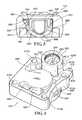
- FIG. 10is a detail perspective view of the valve meter assembly of FIG. 1 at the interface between the solenoid and valve cover as viewed from a position higher than the valve cover.
- FIG. 11is a perspective view of the valve meter assembly of FIG. 1 at the interface between the solenoid and valve cover as viewed from a position lower than the solenoid.
- FIG. 12is a side view of the valve meter assembly of FIG. 1 , including a sectional view of the device housing and valve cover taken in a plane proceeding through the center axis of the solenoid of FIG. 7 and also parallel to a line extending from the inlet of the valve meter assembly to the outlet of the valve meter assembly.
- FIG. 13is a side view of a solenoid attached to a valve cover of another embodiment of a valve meter assembly taken from the same position as FIG. 9 .
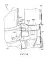
- FIG. 14is another side view of the solenoid and valve cover of the valve meter assembly of FIG. 13 .
- FIG. 15is a side view of a solenoid attached to a valve cover of a third embodiment of a valve meter assembly taken from the same position as FIG. 9 .
- FIG. 16is another side view of the solenoid and valve cover of the valve meter assembly of FIG. 15 .
- FIG. 17is a side view of a solenoid attached to a valve cover of a fourth embodiment of a valve meter assembly taken from the same position as FIG. 9 .
- FIG. 18is another side view of the solenoid and valve cover of the valve meter assembly of FIG. 17 .
- valve meter assemblyDisclosed is a valve meter assembly and associated methods, systems, devices, and various apparatus. It would be understood by one of skill in the art that the disclosed valve is described in but a few exemplary embodiments among many. No particular terminology or description should be considered limiting on the disclosure or the scope of any claims issuing therefrom.
- FIG. 1shows valve meter assembly 1000 with a register device 2210 connected to the top of a device housing 110 of a valve meter device 100 .
- Various embodiment of valve meter assembly 1000also include a communication device.
- the communication devicein some embodiments may be a wireless communication unit 2310 connected to a solenoid 270 (shown in FIG. 2 ) using a solenoid lead wire assembly 2315 .
- the solenoid 270is an actuator. In various embodiments, other actuators may be present in place of the solenoid 270 .
- the wireless communication unit 2310is part of a mesh network where the mesh network includes the remotely located communicator.
- the remotely located communicatormay be operated by a municipality, a technician, a service provider, or another entity.
- the remotely-located communicatormay be any communication device or system including a computer, a server, a gateway, another valve meter assembly, a handheld device, a mesh network, or any other device or system capable of communicating with the wireless communication unit 2310 .
- a bracket(not shown) is provided for attachment of the wireless communication unit 2310 .
- One such bracketis described in FIG. 23 of aforementioned U.S. Patent Publication No. 2012-0305084.
- the device housing 110 of valve meter device 100forms the main body through which water will flow, from inlet 310 to outlet 320 .
- the threaded connections shownare inlet threaded portion 315 and outlet threaded portion 325 , although other types of connections are considered within the scope of this disclosure.
- a valve cover 120is attached to the device housing 110 using valve cover screws 130 a - d ( 130 c,d shown in FIG. 2 ).
- a solenoid tamper cover 140is attached to the top of the valve cover 120 .
- a bottom plate 150is attached to the device housing 110 with bottom plate screws 160 a - d ( 160 c shown in FIG. 2, 160 d not shown).
- references to “top”, “bottom”, “down”, “up”, “downward”, or “upward”refer to the valve meter assembly 1000 as oriented in FIG. 1 .
- Various features of the valve meter assembly 1000may be altered, reoriented, reconfigured, replaced, rotated, or moved in alternative embodiments. No one configuration is intended to be limiting on this disclosure.
- the valve meter device 100includes a valve 170 and a meter 210 (shown in FIG. 2 ).
- the valve 170is partially integrated with the device housing 110 and includes the valve cover 120 screwed onto the device housing 110 to enclose some components of the valve 170 inside a cavity defined between the valve cover 120 and the device housing 110 .
- the current embodimentincludes a partially integrated construction with a separately attached cover, various embodiments are included in this disclosure and may include a plastic welded assembly, separate valve and device housing subassemblies connected together via plastic welding, or separate valve and device housing subassemblies connected together mechanically, among others.
- FIG. 2is an exploded view of the valve meter assembly 1000 including valve meter device 100 , register device 2210 , and wireless communication unit 2310 .
- Register pin 2213 of register device 2210is also shown in FIG. 2 .
- the device housing 110 of valve meter device 100includes a meter portion 264 and a valve portion 265 .
- the device housing 110 and bottom plate 150are configured to enclose meter 210 and a strainer retainer 220 in the meter portion 264 .
- the bottom plate 150is attached to the device housing 110 with bottom plate screws 160 a - d ( 160 d not shown).
- a meter gasket 230is inserted between the bottom plate 150 and the device housing 110 .
- the meter 210 in the current embodimentis a nutating disc displacement flow meter.
- the meter 210has a metering inlet (not shown) and a metering outlet 213 located proximate to each other.
- the metering outlet 213is surrounded by a metering outlet rubber gasket 215 .
- the valve cover 120 and the valve portion 265 of the device housing 110enclose a spring 250 , a diaphragm assembly 260 , and a support ring 263 .
- the solenoid tamper cover 140encloses a solenoid 270 onto the valve cover 120 .
- the valve cover 120includes a valve orifice cylinder 280 (shown in FIG. 4 ) which in the disclosed embodiment is not a separate component but rather a cylindrical boss with an orifice bore 285 concentric to valve orifice cylinder 280 and extending down from the top of valve orifice cylinder 280 .
- Valve orifice cylinder 280is built into the solenoid attachment portion 820 of the valve cover 120 .
- valve orifice cylinder 280could be a separate steel cylinder (disclosed in aforementioned U.S. Patent Publication No. 2012-0305084) with a cylindrical orifice bore extending its entire vertical length.
- the orifice bore 285could be of a constant diameter or it could vary in diameter along its length.
- the orifice bore 285has a narrower inside diameter at the top than at the bottom.
- the valve orifice cylinder 280has a cylindrical shape in the current embodiment, but the valve orifice cylinder 280 may be various shapes in various embodiments.
- the solenoid 270is attached to the valve cover 120 .
- the valve orifice cylinder 280interacts with the solenoid 270 to change water flow through the media channel 520 (shown in FIG. 3 ) when the solenoid 270 is placed in an “open” or a “closed” position.
- a solenoid tamper cover screw 290provides the attachment of the solenoid tamper cover 140 to the valve cover 120 .
- the spring 250may not be required for valve operation.
- Other parts of the valve 170including the solenoid tamper cover 140 or support ring 263 , may not be present in various embodiments of the valve meter device 100 .
- the valve cover 120 and the valve portion 265 of the device housing 110are screwed together to enclose the spring 250 , support ring 263 , and the diaphragm assembly 260 using valve cover screws 130 a,b,c,d .
- Spring 250may not be present in various embodiments.
- register device 2210 and wireless communication unit 2310are described in aforementioned U.S. Patent Publication No. 2012-0305084.
- the device housing 110has an inlet 310 and an outlet 320 (shown in FIG. 1 ). Water flows through the device housing 110 by flowing into the inlet 310 and out of the outlet 320 .
- the inlet 310includes an inlet end 616 (shown in FIG. 1 ), an inlet threaded portion 315 (shown in FIG. 1 ), and an inlet opening 612 (shown in FIG. 1 ).
- the outlet 320includes an outlet end 618 (shown in FIG. 1 ), an outlet threaded portion 325 (shown in FIG. 1 ), and an outlet opening 614 (shown in FIG. 2 ).
- the inlet threaded portion 315 and the outlet threaded portion 325allow for attachment to a piping system, including an upstream piping system or a downstream piping system or both.
- Both the inlet 310 and the outlet 320are attachable to the piping system via the inlet threaded portion 315 and outlet threaded portion 325 , respectively, with a coupling nut (not shown). Details on embodiments of the basic internal structure of the device housing 110 and surrounding components may be found in aforementioned U.S. Patent Publication No. 2012-0305084.
- valve 170(including the valve portion 265 ) and the meter 210 (placed in the meter portion 264 ) are oriented such that at least a portion of each of the valve 170 and the meter 210 touch an imaginary line drawn between the inlet 310 and the outlet 320 thereby forming an “in line” configuration.
- the “in line” configurationis not achieved by staggering valve 170 and the meter 210 , as such staggering may result in unacceptable head loss.
- the “in line” configurationdoes not indicate that components of the valve meter device 100 , including the meter 210 and valve 170 , are located along the same horizontal plane.
- valve meter device 100Should components or features, including the valve 170 and the meter 210 , of the valve meter device 100 be staggered such that the components are not along the same horizontal plane, such a configuration typically is arranged to accommodate other requirements, such as an uneven piping system or multiple inlet or outlet configurations, and not to address the requirement of fitting the valve meter device 100 into a standard water meter lay-length.
- the device housing 110is dimensioned so that it can fit within a standard water meter lay-length.
- the standard water meter lay-length of a standard water meteris designated in various industry standards documents, including the American Water Works Association (AWWA).
- AWWAAmerican Water Works Association
- the AWWA C700 standardrequires 7.5 inches standard water meter lay-length for meters with 5 ⁇ 8-inch piping diameter.
- a top portion 380 of the meter portion 264includes a register connection interface 385 .
- the register connection interface 385includes several teeth 390 a,b,c,d,e,f designed to attach the separate register device 2210 to the top portion 380 .
- a bottom portion 395 of the meter portion 264is configured to accept the bottom plate 150 attaching to the device housing 110 .
- the bottom portion 395 and the bottom plate 150may be connected via a threaded interaction, a screw and bore attachment, or a welded attachment, among others.
- the device housing 110may be composed of brass, bronze, plastic, aluminum, or other non-ferrous material.
- the device housing 110may also be made of ferrous materials based on the specific application.
- the meter portion 264 of the device housing 110is sized to define a meter cavity 450 .
- the meter portion 264need not be a specific shape, but need only accommodate the meter 210 .
- the thickness of each of the walls of meter portion 264is sized to accommodate the water pressure of the piping system and may be variable or constant depending on the method of manufacture and other factors.
- the meter portion 264also includes four threaded bottom plate attachment bores (not shown) for attachment of the bottom plate 150 with the bottom plate screws 160 a,b,c,d.
- the valve portion 265includes four threaded valve cover bores 510 a,b,c,d for attachment of the valve cover 120 to the valve portion 265 of the device housing 110 .
- the valve cover 120is attached using four valve cover screws 130 a,b,c,d that attach through the valve cover 120 to each valve cover bore 510 a,b,c,d .
- the attachmentcould also be achieved using welding, which would obviate any need for valve cover bores 510 a,b,c,d or valve cover screws 130 a,b,c,d.
- FIG. 3Shown in FIG. 3 is a sectional view of valve portion 265 of the device housing 110 also showing a media channel 520 which is a bore that extends from the valve outlet portion 340 to a media channel relief 530 in the device housing 110 .
- a diaphragm ring recess 560lines the top of the valve portion 265 and the media channel relief 530 .
- the beveled edge 550seals the valve 170 in operation.
- Also shown in FIG. 3are horizontal portion 610 , vertical portion 620 , slanted bottom portion 345 , top edge portion 640 , and valve inlet portion 330 .
- FIG. 4is a perspective view and FIG. 5 is a top view of one embodiment of valve cover 120 .
- Four screw bores 810 a,b,c,dare located at the corners of the valve cover 120 .
- a solenoid attachment portion 820is a cylindrical boss including a solenoid attachment sink 825 on the inside of the boss, the solenoid attachment sink 825 defining a depressed area in the solenoid attachment portion 820 configured to accepted at least a portion of solenoid 270 .
- This solenoid attachment sinkmay have a threaded portion and be identified as a threaded solenoid attachment sink.
- the valve cover attachment portionmay have a threaded portion to match with the threaded solenoid attachment sink and may be identified as a threaded valve cover attachment portion.
- a valve orifice cylinder 280defines an orifice bore 285 which is connected to a valve cover media channel 830 (shown in FIG. 6 ).
- the valve orifice cylinder 280 , orifice bore 285 , and valve cover media channel 830are aligned with the center of the solenoid attachment sink 825 in the current embodiment and are aligned with the media channel 520 (shown in FIG. 3 ) of the device housing 110 when the valve meter device 100 is assembled.
- a valve cavity media channel 840(shown in FIG. 5 ) is also shown in the solenoid attachment portion 820 .
- the valve cover 120 in the current embodimentalso includes molded recesses 850 .
- a threaded solenoid cover screw bore 870is located in a lug 875 .
- the valve cover 120is about square in shape, one side of the valve cover 120 includes a curve 880 .
- the curve 880is included to provide clearance for the register device 2210 to be placed on the valve meter device 100 .
- a countercurve protrusion 890is proximate the bottom of the curve 880 to accommodate the diaphragm ring recess 930 .
- Valve cover mechanical stop 6000Extending from the outer edge of solenoid attachment portion 820 toward the side of the valve cover including lug 875 and screw bore 810 c is valve cover mechanical stop 6000 .
- Valve cover mechanical stop 6000includes top 6010 , front 6020 , and rear 6030 (shown in FIG. 5 ). Rear 6030 in the current embodiment is aligned with the three o'clock position when viewing the top of the valve cover 120 with the solenoid attachment portion 820 at the upper position on the valve cover 120 .
- the valve cover 120includes a valve cavity 905 .
- the valve cavity 905 and the valve portion 265(shown in FIG. 3 ) enclose components of the diaphragm assembly 260 (shown in FIG. 2 ).
- the valve cavity 905 and the valve portion 265may also enclose the spring 250 and support ring 263 (both shown in FIG. 2 ).
- the valve cavity 905also includes a valve recess 910 and a valve bonnet 920 , which together are shaped to accept the diaphragm assembly 260 and the spring 250 and the support ring 263 .
- the valve cover 120also includes a diaphragm ring recess 930 shaped to align with the diaphragm ring recess 560 .
- the solenoid attachment portion 820is dimensioned to define a solenoid chamber 940 between the solenoid 270 and the valve cover 120 when the solenoid 270 is attached to the valve cover 120 .
- the valve cavity media channel 840connects the valve cavity 905 with the solenoid chamber 940 .
- the valve cavity media channel 840is shown to connect with both the valve recess 910 and a valve bonnet 920 in the current embodiment, the valve cavity media channel 840 may connect to any portion of the valve cavity 905 , including the valve recess 910 .
- valve cover media channel 830is aligned with the center of the solenoid attachment portion 820 and solenoid attachment sink 825 , the valve cover media channel 830 connects to the orifice bore 285 to the solenoid chamber 940 .
- Valve orifice cylinder 280is positioned at the top of valve cover media channel 830 and is part of valve cover 120 but may be manufactured as a separate component in other embodiments and added to valve cover 120 by welding, screwing, interference fit and any one of a number of other commonly available fastening methods
- FIG. 7shows a perspective view
- FIG. 8shows a side view of one embodiment of the solenoid 270 of the valve meter device 100 .
- the solenoid 270includes a solenoid body 1110 , a valve cover attachment portion 500 incorporating threaded attachment portion 1120 , plunger 1130 , and solenoid lead wire assembly 2315 .
- the plunger 1130includes a shaft portion 1135 (not shown) and an interface portion 1140 .
- the solenoid in the current embodimentis designed to be attached via threaded interaction, other attachment means are contemplated, including glue, welding, snap-in or click-in, and screw bore attachments among others.
- the solenoid tamper cover 140(shown in FIGS. 1 and 2 ) covers the solenoid 270 when the valve meter device 100 is assembled. When the valve meter device 100 is assembled, the interface portion 1140 of the plunger 1130 may contact and seal the orifice bore 285 , as will be described later.
- a solenoid mechanical stop 3000having a bottom 3010 , a front 3020 (shown in FIG. 8 ), and a rear 3030 .
- the solenoid mechanical stop 3000is part of solenoid body 1110 and is located at the bottom outer edge of the solenoid body 1110 and protrudes from an outer surface of solenoid body 1110 .
- the height of the solenoid mechanical stop 3000is sized so as not to interface with the valve cover mechanical stop 6000 (shown in at least FIGS.
- valve cover mechanical stop 6000protrudes from an outer surface of the solenoid attachment portion 820 of valve cover 120 .
- the valve cover mechanical stop 6000may protrude from inside the solenoid attachment sink 825 engagable with the solenoid mechanical stop 3000 protruding from the valve cover attachment portion 500 .
- the valve cover mechanical stop 6000 and solenoid mechanical stop 3000may not be visible once the solenoid is installed in the valve cover 120 .
- a radial dimension of the solenoid mechanical stop 3000is sized so as to interface with the valve cover mechanical stop 6000 but rotate freely about solenoid attachment portion 820 of valve cover 120 .
- Front 3020 and rear 6030are co-planar when the threaded attachment portion 1120 of solenoid 270 is fully engaged inside solenoid attachment sink 825 and front 3020 comes in contact with rear 6030 (shown in FIG. 10 ).
- the gap between the interface portion 1140 of plunger 1130 of solenoid 270can be precisely set by preventing over-tightening or over-torqueing of threaded attachment portion 1120 of valve cover attachment portion 500 inside solenoid attachment sink 825 .
- FIG. 9is a sectional view of valve cover 120 also showing a side view of solenoid 270 as seated in valve cover 120 .
- gasket 900In between solenoid 270 and valve cover 120 at the bottom of solenoid attachment sink 825 is gasket 900 .
- Gasket 900may be made from any flexible material including but not limited to rubber, EPDM, or silicone, and is sized to prevent water penetration into any space that may remain between solenoid attachment sink 825 and valve cover attachment portion 500 when solenoid 270 is properly seated in solenoid attachment sink 825 .
- Interface portion 1140 of plunger 1130is shown spaced away from orifice bore 285 defined in valve orifice cylinder 280 . As described in a similar embodiment in U.S. Patent Publication No.
- valve 170is a pilot-operated valve and will shut off the flow of fluid through the valve 170 when valve cover media channel 830 is sealed off from solenoid chamber 940 when interface portion 1140 of plunger 1130 of solenoid 270 comes in contact with orifice bore 285 of valve orifice cylinder 280 .
- solenoid 270may not be fully tightened or it may be over-tightened in solenoid attachment sink 825 .
- solenoid 270is not fully tightened, gap 287 between interface portion 1140 and orifice bore 285 may not completely close when valve 170 receives a valve control signal to close, and therefore operation of valve 170 and therefore flow through valve 170 may be affected. In this case, for example, water may continue to flow through valve 170 even though valve 170 has received a valve control signal to turn off the flow. If solenoid 270 is over-tightened—and this is possible even though solenoid body 1110 comes in contact with solenoid attachment portion 820 —gap 287 between interface portion 1140 and orifice bore 285 may remain partially or completely closed even when valve 170 receives a valve control signal to open, and therefore operation of valve 170 and therefore flow through valve 170 may be affected. In this case, for example, water flow through valve 170 may be partially or completely restricted even though valve 170 has received a valve control signal to open.
- FIG. 10 and FIG. 11show two different perspective views of solenoid 270 with solenoid mechanical stop 3000 engaged with valve cover mechanical stop 6000 of valve cover 120 as in FIG. 10 or in close proximity with each other as in FIG. 11 .
- FIG. 12is side view of the valve meter assembly 1000 with a sectional view of the valve cover 120 and the device housing 110 .
- Valve cover mechanical stop 6000can be seen extending from valve cover 120 between solenoid attachment portion 820 and valve cover screw 130 c .
- Interface portion 1140 of plunger 1130can be seen covering orifice bore 285 .
- the engagement of solenoid mechanical stop 3000 and/or valve cover mechanical stop 6000may be accompanied by a tactile and/or audible snap or click or other sound to confirm for someone who is building or servicing or otherwise handling the valve 170 that engagement has occurred.
- This engagement of the solenoid mechanical stop 3000 and/or valve cover mechanical stop 6000may also be accompanied by a visual indication. This visual indication may come in the form of front 3020 of solenoid mechanical stop 3000 physically interfacing with rear 6030 of valve cover mechanical stop 6000 such that no gap is visible between front 3020 and rear 6030 .
- FIG. 13is a side view of another embodiment of valve 170 , wherein the threaded attachment portion 1120 and solenoid attachment sink 825 of the above-described embodiment are replaced with a plug connection and socket connection, respectively, neither requiring threads and wherein the solenoid 270 ′ is precisely positioned and secured with valve cover mechanical stops 1300 a,b .
- Valve cover mechanical stops 1300 a,bfunction as snap levers and are incorporated into valve cover 120 ′.
- the plug connection of solenoid 270 ′is so named because it defines a cylindrical structure at one end of solenoid 270 ′ that fits inside the socket connection of valve cover 120 ′.
- Valve cover mechanical stops 1300 a,binclude bend portion 1305 a,b and engagement portion 1310 a,b .
- valve cover mechanical stop 1300 a,bmay be considered a snap lever because it functions as a lever—with a lever arm represented by bend portion 1305 a,b rotatable about a pivot—and snaps into position during engagement with solenoid mechanical stop 1320 a,b although engagement may or may not be accompanied by an audible snap.
- Gusset 1315 a,bis used to reinforce the base of each valve cover mechanical stop 1300 a,b by increasing the area of attachment of valve cover mechanical stops 1300 a,b to solenoid attachment portion 820 ′ of valve cover 120 ′ while still providing clearance for valve cover screws 130 c,d .
- Two valve cover mechanical stops 1300 a,bare shown in the current embodiment with a plug connection (not shown) and socket connection (not shown) similar in size to the threaded variation, but in other embodiments it may be desirable to have more than two valve cover mechanical stops 1300 a,b or to have valve cover mechanical stops of a different size and shape and engagement method depending on the desired security of the engagement, the system water pressure, and other factors.
- the security of the engagementcould be changed by changing the stiffness and quantity of the valve cover mechanical stops and the shape of the engagement portion, for example. Additionally, it may be desirable to have a deeper or taller attachment socket and/or attachment plug to further stabilize the assembled solenoid 270 ′.
- FIG. 14is another side view of the valve 170 shown in FIG. 13 . Shown is valve cover mechanical stop 1300 b ( 1300 a not shown) and also solenoid mechanical stop 1320 b ( 1320 a not shown). Solenoid mechanical stop 1320 a,b may be considered a detent because it holds valve cover mechanical stop 1300 b and therefore also solenoid 270 ′ in position. Solenoid mechanical stops 1320 a,b in the disclosed embodiment have a height, width, and depth that is large enough to accommodate the engagement portion 1310 a,b of valve cover mechanical stops 1300 a,b .
- solenoid mechanical stops 1320 a,bcould be replaced with a single groove or recess (not shown) around the full perimeter of the solenoid 270 ′ in applications where it might be desirable to install solenoid 270 ′ only with regard to its vertical placement and without regard to the precise rotational orientation of solenoid 270 ′ with respect to valve cover 120 ′.
- the engagement of the valve cover mechanical stops 1300 a,b and/or solenoid mechanical stops 1320 a,bmay be accompanied by a tactile and/or audible snap or click or other sound to confirm for someone who is building or servicing or otherwise handling the valve 170 that engagement has occurred.
- This engagement of the valve cover mechanical stops 1300 a,b and/or solenoid mechanical stops 1320 a,bmay also be accompanied by a visual indication.
- This visual indicationmay come in the form of valve cover mechanical stops 1300 a,b physically moving into the solenoid mechanical stops 1320 a,b .
- there is one orientation of the solenoid 270 ′that will cause bend portions 1305 a,b of valve cover mechanical stops 1300 a,b to rest in an unbent, vertical position.
- FIGS. 15 and 16are side views of another embodiment of valve 170 , wherein the threaded attachment portion 1120 and solenoid attachment sink 825 remain but the solenoid mechanical stop 1500 sets the rotational and therefore also the vertical position of solenoid 270 ′′ with respect to valve cover 120 ′′.
- Solenoid mechanical stop 1500includes bend portion 1505 and engagement portion 1510 .
- Valve cover mechanical stop 1520defining width 1525 which is greater than width 1530 of solenoid mechanical stop 1500 , prevents solenoid 270 ′′ from being rotated too little or too much by providing a positive stop for solenoid mechanical stop 1500 to positively lock in valve cover mechanical stop 1520 , thereby preventing over-tightening or under-tightening of solenoid 270 ′′ in solenoid attachment sink 825 of solenoid attachment portion 820 ′′.
- Valve cover mechanical stop 1520may also be considered a detent in various embodiments because it holds solenoid mechanical stop 1500 in position. As a detent, valve cover mechanical stop 1520 precisely sets the position of solenoid 270 ′′ to ensure its proper opening and closing function.
- solenoid mechanical stop 1500may be considered a snap lever because it functions as a lever—with a lever arm represented by bend portion 1505 rotatable about a pivot—and snaps into position during engagement with valve cover mechanical stop 1520 although engagement may or may not be accompanied by an audible snap.
- the solenoid mechanical stop 1500is of a different size or shape or engagement method.
- the valve cover mechanical stop and solenoid mechanical stopcould be engagable via a fastener such as a round pin, screw, bolt, cotter pin, or canoe clip extending radially into a matching hole in the valve cover.
- the engagement of the solenoid mechanical stop 1500 and/or valve cover mechanical stop 1520may be accompanied by a tactile and/or audible snap or click or other sound to confirm for someone who is building or servicing or otherwise handling the valve 170 that engagement has occurred.
- This engagement of the solenoid mechanical stop 1500 and/or valve cover mechanical stop 1520may also be accompanied by a visual indication. This visual indication may come in the form of solenoid mechanical stop 1500 physically moving into the valve cover mechanical stop 1520 . In the current embodiment, there is one orientation of the solenoid 270 ′′ that will cause bend portion 1505 of solenoid mechanical stop 1500 to rest in an unbent, vertical position.
- FIGS. 17 and 18are side views of yet embodiment of valve 170 , wherein the threaded attachment portion 1120 and solenoid attachment sink 825 of solenoid attachment portion 820 ′′′ remains but the valve cover mechanical stop 1700 of solenoid attachment portion 820 ′′′ sets the rotational position of solenoid 270 ′′′ with respect to valve cover 120 ′′′.
- Valve cover mechanical stop 1700includes bend portion 1705 and engagement portion 1710 .
- Solenoid mechanical stop 1720 in solenoid 270 ′′′engages engagement portion 1710 of valve cover mechanical stop 1700 and thereby prevents solenoid 270 ′′′ from being rotated too little or too much by providing a positive stop for solenoid 270 ′′′, thereby preventing over-tightening or under-tightening of solenoid 270 ′′′.
- Solenoid mechanical stop 1720may also be considered a detent in various embodiments because it holds valve cover mechanical stop 1700 in place. As a detent, solenoid mechanical stop 1720 precisely sets the position of valve cover mechanical stop 1700 and therefore also solenoid 270 ′′′ to ensure its proper opening and closing function.
- valve cover mechanical stop 1700may be considered a snap lever because it functions as a lever—with a lever arm represented by bend portion 1705 rotatable about a pivot—and snaps into position during engagement with solenoid mechanical stop 1720 although engagement may or may not be accompanied by an audible snap.
- the engagement of the solenoid mechanical stop 1720 and/or valve cover mechanical stop 1700may be accompanied by a tactile and/or audible snap or click or other sound to confirm for someone who is building or servicing or otherwise handling the valve 170 that engagement has occurred.
- This engagement of the solenoid mechanical stop 1720 and/or valve cover mechanical stop 1700may also be accompanied by a visual indication. This visual indication may come in the form of valve cover mechanical stop 1700 physically moving into the solenoid mechanical stop 1720 . In the current embodiment, there is one orientation of the solenoid 270 ′′′ that will cause bend portion 1705 of valve cover mechanical stop 1700 to rest in an unbent, horizontal position.
- the wireless communication unit 2310may receive signals from the remotely located communicator, or send signals to the remotely located communicator, or both.
- the signalsmay include valve control signals.
- the valve control signalsmay direct action of the solenoid 270 to open or to close and, thereby, to change the state of valve 170 .
- the valve orifice cylinder 280provides the interface with the interface portion 1140 of the plunger 1130 .
- the valve orifice cylinder 280is chosen of an appropriate size to prevent excessive fluid flow, as excessive fluid flow will cause the diaphragm assembly 260 to lift away from the beveled edge 550 more quickly than may be desired.
- the valve 170is a pilot-operated valve.
- a pilot operated valveis a valve that experiences large-scale operation occurring naturally as a result of a small change in the pilot. As such, small amounts of energy can be used to control large-scale changes as the pilot changes.
- the pilot-operated valveis a diaphragm valve.
- the valve meter device 100may assume one of two states: an “on” or “open” state and an “off” or “closed” state.
- a “trickle” or “reduced flow” statemay be substituted for the “off” or “closed” state in various embodiments.
- the valve meter device 100may be configured to assume either of the two possible states.
- the statescorrespond to the positioning of the valve 170 .
- the valve meter device 100will typically be in the open state allowing a maximum, or near maximum, flow rate of water that is allowed to flow through the valve meter device 100 .
- maximum flow rateis about 25 gallons per minute, although other maximum flow rates are possible in accord with this disclosure.
- valve meter assembly 1000water travels through the valve meter device 100 originating from a water source and entering in inlet 310 . Water is permitted to travel through the inlet opening 612 , and to the horizontal portion 610 . When water reaches the intersection of the horizontal portion 610 and vertical portion 620 , water is directed vertically into the vertical portion 620 by water pressure. Water exits the vertical portion 620 by flowing over the beveled edge 550 . Water fills the valve transition portion 670 and—as will be described in more detail later—the valve cavity 905 and a media channel pathway 2610 , which extends from the valve cavity 905 to the valve outlet portion 340 .
- meter 210is a nutating disc displacement flow meter
- the water passing through the meter 210moves a nutating disc (not shown) causing a meter magnet (not shown) to rotate.
- the rotation of the meter magnetcauses a register to log the motion, leading to a measurement of water usage and a readout of water usage from the register.
- a register circuitconfigured to log the readout of water usage at preset timing intervals may be included with one embodiment of the valve meter device 100 .
- the register circuitremains in a low power mode for the majority of its operating life.
- Low powermeans that the register circuit is using a very small amount of power when compared to the normal operating mode. This is commonly referred to as being in a “sleep mode.”
- the register circuit“wakes up” at preset timing intervals to read the register and log the readout.
- a wireless communication unit circuit(not shown) is connected with the register circuit via wires 2360 (shown in FIG. 1 ).
- the wireless communication unit circuitobtains the log of the register circuit and transmits the log to a remotely located communicator at preset timing intervals.
- the preset timing interval of the wireless communication unit 2310may or may not be the same preset timing interval as that of the register circuit. In alternative embodiments, a separate register circuit may not be necessary if the wireless communication unit 2310 is capable of directly determining the measurement of water usage of the register.
- the valve 170is configured in the open state when the interface portion 1140 is lifted away from the valve orifice cylinder 280 because the solenoid 270 is in the open position.
- the valve cavity media channel 840provides a water pressure link between the solenoid chamber 940 and the valve cavity 905 such that the water pressure in the valve cavity 905 will be the same as the water pressure in the solenoid chamber 940 .
- the solenoid 270is in the open position, the plunger 1130 is lifted so that the valve orifice cylinder 280 is open to the valve cover media channel 830 .
- valve orifice cylinder 280When the valve orifice cylinder 280 is uncovered, water is allowed to flow from the solenoid chamber 940 through the valve cover media channel 830 into the media channel 520 and further into the valve outlet portion 340 . Therefore, the water pressure in the valve cavity 905 is substantially the same as the water pressure in the media channel 520 , the solenoid chamber 940 , the media channel 520 , and the valve outlet portion 340 . Thus, the diaphragm has no pressure behind it to close the valve 170 . The valve 170 remains open.
- valve orifice cylinder 280located on the valve cover media channel 830 such that there is a pressure link between the valve cavity 905 and the solenoid chamber 940
- the valve orifice cylinder 280may be located within the valve cavity media channel 840 in various embodiments. Other locations for the valve orifice cylinder 280 and orifice bore 285 are also contemplated by the current disclosure.
- valve 170Changing the valve meter device 100 to a closed state requires the valve 170 to be changed to closed.
- a trickle stateis included, the water supply valve must be changed to a trickle state, which may be the same as the closed state in various embodiments. This is accomplished by operation of the plunger 1130 moving into a closed position having the interface portion 1140 contacting the valve orifice cylinder 280 , which provides a water-tight seal over the valve cover media channel 830 .
- the valve meter device 100In the closed state, the valve meter device 100 allows no water flow through.
- the valve meter device 100allows minimal water flow through.
- the valve 170is a diaphragm valve with a pressure-controlled pilot operation.
- the solenoid 270is engaged, or “thrown,” and closed onto the valve orifice cylinder 280 . This closes or “severs” the media channel pathway 2610 . Water flow is blocked from the solenoid chamber 940 to the valve cover media channel 830 as well as to the media channel 520 and media channel relief 530 thereby isolating the solenoid chamber 940 , the valve cavity media channel 840 , and the valve cavity 905 as one water pressure pool.
- the closing of the solenoid 270is the pilot operation that triggers the dynamic state of the valve 170 .
- the valve 170is in the closed state when the interface portion 1140 of the plunger 1130 is in contact with the valve orifice cylinder 280 and the diaphragm assembly 260 has traveled and contacted the beveled edge 550 , sealing the valve 170 .
- valve cavity 905no longer has media pressure behind it.
- Spring force provided from the diaphragm or from the optional spring 250forces the diaphragm assembly 260 down toward the valve inlet portion 330 of the device housing 110 .
- the spring 250is optional because, depending on the configuration of the diaphragm, the diaphragm may already be biased toward closing the valve 170 without the spring 250 .
- the diaphragm assembly 260moves toward the valve inlet portion 330 , some of the water flowing through the valve portion 265 will leak through the diaphragm assembly 260 and into the valve cavity 905 .
- valve cavity 905The increased volume of water in the valve cavity 905 creates increased pressure in the valve cavity 905 .
- the increased pressure in the valve cavity 905is applied to the entire surface of the diaphragm because the valve cavity 905 extends across the entire diaphragm. This increased pressure applied over the entire diaphragm further biases the diaphragm assembly 260 in the direction of the valve inlet portion 330 .
- the increased biascauses the diaphragm assembly 260 to travel toward the valve inlet portion 330 , eventually seating the bottom of an inner flat portion (not shown) of the diaphragm onto the beveled edge 550 of the top edge portion 640 of the valve inlet portion 330 .
- the valve 170is in the closed state.
- valve 170remains in the closed state because the cross-section of the valve inlet portion 330 provides a smaller surface area over which to apply pressure to the diaphragm than the surface area of the diaphragm 1230 that interfaces with the valve cavity 905 .
- a smaller surface area over which the pressure is appliedproduces a smaller force than the same pressure applied to a larger surface area.
- the trickle stateis accomplished by placing the diaphragm in the same position as the diaphragm 1230 is placed in the closed state. However, in the trickle state, a small amount of water is allowed to bypass the valve 170 via a leak passageway (not shown) defined in the diaphragm or a bypass channel (not shown) from the valve inlet portion 330 to the valve outlet portion 340 .
- the bypass channel or leak passagewaymay be a small bore leading from the valve inlet portion 330 to the valve outlet portion 340 and may be placed in the vertical portion 620 , for example. The bore would be small enough that a significant amount of water would not flow through the bore.
- a sealing valvemay allow selective flow through the bore.
- the solenoid 270is actuated so that the interface portion 1140 lifts away from the valve orifice cylinder 280 , opening the media channel pathway 2610 . Opening the media channel pathway 2610 establishes a pressure link between all of the components of the media channel pathway 2610 , including the valve cavity 905 , the valve cavity media channel 840 , the solenoid chamber 940 , the valve cover media channel 830 , the media channel relief 530 , and the media channel 520 .
- the pressure in the valve cavity 905is reduced, the downward force on the diaphragm and the diaphragm assembly 260 is also reduced.
- the pressure in the valve inlet portion 330provides greater upward force on the bottom of the diaphragm than the downward force on the top of the diaphragm. This downward force may be provided by the spring 250 or by the inherent bias of the diaphragm. The result is a lifting of the diaphragm assembly 260 , thereby opening the valve 170 .
- the solenoid 270may be engaged or lifted by manual operation, by electronic actuation, or by remote control.
- the wireless communication unit 2310is capable of receiving electrical signals for the solenoid 270 to control its operation.
- Actuation of the plunger 1130 in the current embodimentis performed by a solenoid 270 , which is a latching solenoid in the current embodiment.
- a latching solenoidis a solenoid 270 that latches in place.
- a latching solenoiddoes not utilize energy once it has achieved its desired position but does use energy to change positions.
- this actuationcan be performed via a number of mechanical or electromechanical interfaces, including stepper motors, DC motors, non-latching solenoids, electromagnets and other electromagnetic devices, and spring assemblies, among others.
- This embodimentwould allow a remotely located communicator to control operation of the valve 170 , allowing the valve 170 to be changed to an open or closed state from a remote location.
- conditional languagesuch as, among others, “can,” “could,” “might,” or “may,” unless specifically stated otherwise, or otherwise understood within the context as used, is generally intended to convey that certain embodiments include, while other embodiments do not include, certain features, elements and/or steps. Thus, such conditional language is not generally intended to imply that features, elements and/or steps are in any way required for one or more particular embodiments or that one or more particular embodiments necessarily include logic for deciding, with or without user input or prompting, whether these features, elements and/or steps are included or are to be performed in any particular embodiment.
Landscapes
- Engineering & Computer Science (AREA)
- General Engineering & Computer Science (AREA)
- Mechanical Engineering (AREA)
- Physics & Mathematics (AREA)
- Electromagnetism (AREA)
- General Physics & Mathematics (AREA)
- Automation & Control Theory (AREA)
- Magnetically Actuated Valves (AREA)
Abstract
Description
Claims (21)
Priority Applications (3)
| Application Number | Priority Date | Filing Date | Title |
|---|---|---|---|
| US14/273,823US9494249B2 (en) | 2014-05-09 | 2014-05-09 | Mechanical stop for actuator and orifice |
| US15/288,156US9909680B2 (en) | 2014-05-09 | 2016-10-07 | Mechanical stop for actuator and orifice |
| US15/877,812US10871240B2 (en) | 2014-05-09 | 2018-01-23 | Mechanical stop for actuator and orifice |
Applications Claiming Priority (1)
| Application Number | Priority Date | Filing Date | Title |
|---|---|---|---|
| US14/273,823US9494249B2 (en) | 2014-05-09 | 2014-05-09 | Mechanical stop for actuator and orifice |
Related Child Applications (1)
| Application Number | Title | Priority Date | Filing Date |
|---|---|---|---|
| US15/288,156ContinuationUS9909680B2 (en) | 2014-05-09 | 2016-10-07 | Mechanical stop for actuator and orifice |
Publications (2)
| Publication Number | Publication Date |
|---|---|
| US20150323091A1 US20150323091A1 (en) | 2015-11-12 |
| US9494249B2true US9494249B2 (en) | 2016-11-15 |
Family
ID=54367469
Family Applications (3)
| Application Number | Title | Priority Date | Filing Date |
|---|---|---|---|
| US14/273,823Active2034-09-23US9494249B2 (en) | 2014-05-09 | 2014-05-09 | Mechanical stop for actuator and orifice |
| US15/288,156ActiveUS9909680B2 (en) | 2014-05-09 | 2016-10-07 | Mechanical stop for actuator and orifice |
| US15/877,812ActiveUS10871240B2 (en) | 2014-05-09 | 2018-01-23 | Mechanical stop for actuator and orifice |
Family Applications After (2)
| Application Number | Title | Priority Date | Filing Date |
|---|---|---|---|
| US15/288,156ActiveUS9909680B2 (en) | 2014-05-09 | 2016-10-07 | Mechanical stop for actuator and orifice |
| US15/877,812ActiveUS10871240B2 (en) | 2014-05-09 | 2018-01-23 | Mechanical stop for actuator and orifice |
Country Status (1)
| Country | Link |
|---|---|
| US (3) | US9494249B2 (en) |
Cited By (6)
| Publication number | Priority date | Publication date | Assignee | Title |
|---|---|---|---|---|
| US20170023146A1 (en)* | 2014-05-09 | 2017-01-26 | Mueller International, Llc | Mechanical stop for actuator and orifice |
| US9857265B2 (en)* | 2015-04-03 | 2018-01-02 | Richard Andrew DeVerse | Methods and systems for detecting fluidic levels and flow rate and fluidic equipment malfunctions |
| US10655999B2 (en) | 2011-05-31 | 2020-05-19 | Mueller International, Llc | Valve meter assembly and method |
| JP2021513038A (en)* | 2018-02-09 | 2021-05-20 | ノードソン コーポレーションNordson Corporation | Multi-port valve |
| US12292317B2 (en) | 2022-02-28 | 2025-05-06 | Mueller International, Llc | Ultrasonic flow meter assembly |
| US12443208B2 (en) | 2023-02-08 | 2025-10-14 | Rain Bird Corporation | Control zone devices, systems and methods |
Families Citing this family (4)
| Publication number | Priority date | Publication date | Assignee | Title |
|---|---|---|---|---|
| CA2826677A1 (en)* | 2011-02-04 | 2012-08-09 | Mark Churchill | Fluid pump volute diversion system, solids collection system and related methods for a washing machine |
| KR101521569B1 (en)* | 2014-05-28 | 2015-05-20 | 우성전기공업 주식회사 | electromagnetic valve for controlling water supply |
| US11306844B2 (en) | 2017-06-26 | 2022-04-19 | Lixil Corporation | Pilot solenoid valve |
| CN111071976B (en)* | 2019-11-26 | 2024-05-31 | 河南正大航空工业股份有限公司 | Anti-overflow plug-in structure of communicating vessel and composition method of communicating vessel |
Citations (353)
| Publication number | Priority date | Publication date | Assignee | Title |
|---|---|---|---|---|
| US691904A (en) | 1898-08-20 | 1902-01-28 | David Verner Hallbergh | Water-meter. |
| US1165429A (en) | 1915-01-15 | 1915-12-28 | Adolph Mass | Liquid-meter. |
| US1788618A (en) | 1929-11-06 | 1931-01-13 | Berkey E Cover | Signal system |
| US1808209A (en) | 1923-12-21 | 1931-06-02 | Earl George Goodell | Fluid metering system and apparatus |
| US1808212A (en) | 1931-06-02 | Meter | ||
| US2302529A (en) | 1939-03-07 | 1942-11-17 | Pittsburgh Equitable Meter Co | Dfpeating valve shutoff system |
| US3254660A (en) | 1963-12-19 | 1966-06-07 | Itt | Closure operator for valves |
| US3593957A (en) | 1969-08-15 | 1971-07-20 | Eaton Yale & Towne | Diaphragm assembly for pressure operated pilot controlled shutoff valve |
| US3653261A (en) | 1970-03-06 | 1972-04-04 | Richard Ruben | Pressure demand meter for fluid flow measurement |
| US3672233A (en)* | 1970-07-06 | 1972-06-27 | Clare & Co C P | Actuator mechanism |
| US3705385A (en) | 1969-12-10 | 1972-12-05 | Northern Illinois Gas Co | Remote meter reading system |
| US3731534A (en) | 1970-11-18 | 1973-05-08 | Rockwell Mfg Co | Housing structure for meters |
| US3795144A (en) | 1972-02-17 | 1974-03-05 | R Marchesi | Tamper-proof water meter |
| US4093997A (en) | 1976-09-17 | 1978-06-06 | General Electric Company | Portable programmer for time-of-day metering register system and method of using same |
| US4120031A (en) | 1976-07-19 | 1978-10-10 | Energy Conservation Systems, Inc. | Utility usage monitoring systems |
| US4291375A (en) | 1979-03-30 | 1981-09-22 | Westinghouse Electric Corp. | Portable programmer-reader unit for programmable time registering electric energy meters |
| US4388690A (en) | 1979-10-11 | 1983-06-14 | Ael Microtel Limited | Automatic meter reading transponder |
| US4414633A (en) | 1980-11-17 | 1983-11-08 | British Gas Corporation | Data processing and recording apparatus |
| US4442492A (en) | 1979-08-21 | 1984-04-10 | Karlsson Bjoern G E | Device for central reading and registration of customers' power consumption |
| US4465970A (en) | 1981-02-26 | 1984-08-14 | General Electric Company | Method and apparatus for multiple rate metering of electrical energy |
| US4516213A (en) | 1982-02-01 | 1985-05-07 | E. Grant Deans | Multiple rate metering system |
| US4542469A (en) | 1982-08-12 | 1985-09-17 | Duncan Electric Company, Inc. | Programmable demand register with two way communication through an optical port and external reading devices associated therewith |
| US4591988A (en) | 1983-07-13 | 1986-05-27 | Control Energy Corporation | Energy cost allocation method and system |
| US4707852A (en) | 1981-10-09 | 1987-11-17 | Systems And Support, Incorporated | Utility usage data and event data acquisition system |
| JPS62295674A (en) | 1986-06-16 | 1987-12-23 | 松下電工株式会社 | Disasters preventing monitor control system |
| US4727900A (en) | 1986-12-11 | 1988-03-01 | Dooling Joseph S | Tamper-proof hydrant cover |
| US4792946A (en) | 1987-04-07 | 1988-12-20 | Spectrum Electronics, Inc. | Wireless local area network for use in neighborhoods |
| US4803632A (en) | 1986-05-09 | 1989-02-07 | Utility Systems Corporation | Intelligent utility meter system |
| US4833618A (en) | 1986-02-20 | 1989-05-23 | Net Laboratories, Inc. | System for automatically reading utility meters from a remote location |
| US4868566A (en) | 1988-05-03 | 1989-09-19 | Badger Meter, Inc. | Flexible piezoelectric switch activated metering pulse generators |
| US4881070A (en) | 1985-06-21 | 1989-11-14 | Energy Innovations, Inc. | Meter reading methods and apparatus |
| US4901751A (en) | 1989-06-15 | 1990-02-20 | Systems Chemistry, Inc. | Fluid control valve and system with leak detection and containment |
| US4940976A (en) | 1988-02-05 | 1990-07-10 | Utilicom Inc. | Automated remote water meter readout system |
| US4953403A (en) | 1989-03-15 | 1990-09-04 | Binks Manufacturing Company | Positive displacement flushable flow meter |
| US4967996A (en) | 1988-06-28 | 1990-11-06 | Masako Kiyohara | Pilot type controlled electromagnetic valve system |
| US4989830A (en) | 1990-01-26 | 1991-02-05 | Ratnik Industries, Inc. | Motorized hydrant |
| US5056107A (en) | 1990-02-15 | 1991-10-08 | Iris Systems Inc. | Radio communication network for remote data generating stations |
| US5075792A (en) | 1989-03-20 | 1991-12-24 | Hewlett-Packard Company | Low power optical transceiver for portable computing devices |
| US5079715A (en) | 1987-12-28 | 1992-01-07 | Krishnan Venkataraman | Electronic data recorder for electric energy metering |
| US5121344A (en) | 1989-07-03 | 1992-06-09 | The United States Of America As Represented By The Secretary Of The Interior | Method of locating underground mines fires |
| US5239575A (en) | 1991-07-09 | 1993-08-24 | Schlumberger Industries, Inc. | Telephone dial-inbound data acquisition system with demand reading capability |
| JPH05253316A (en) | 1992-03-12 | 1993-10-05 | Senju Sprinkler Kk | Extinguishing equipment |
| US5251480A (en) | 1992-06-02 | 1993-10-12 | Schlumberger Industries, Inc. | Frost-proof drive shaft for water meter |
| US5267587A (en) | 1992-04-07 | 1993-12-07 | Brown Geoffrey P | Utilities shutoff system |
| US5298894A (en) | 1992-06-17 | 1994-03-29 | Badger Meter, Inc. | Utility meter transponder/antenna assembly for underground installations |
| JPH06223279A (en) | 1993-01-26 | 1994-08-12 | Nohmi Bosai Ltd | Tunnel disaster preventing equipment |
| US5381136A (en) | 1993-03-19 | 1995-01-10 | Northern Illinois Gas Company | Remote data collection and monitoring system for distribution line |
| US5434911A (en) | 1993-06-04 | 1995-07-18 | M & Fc Holding Company, Inc. | Call in-bound remote reading and data collection system |
| US5438329A (en) | 1993-06-04 | 1995-08-01 | M & Fc Holding Company, Inc. | Duplex bi-directional multi-mode remote instrument reading and telemetry system |
| JPH07231363A (en) | 1994-02-18 | 1995-08-29 | Toyo Puropan Gas Kk | Emergency call network system |
| US5451938A (en) | 1993-10-22 | 1995-09-19 | Schlumberger Industries, Inc. | RF meter reading system |
| US5459459A (en) | 1992-12-28 | 1995-10-17 | General Electric Company | Method and apparatus for transmitting data from an energy meter |
| JPH07116285B2 (en) | 1989-01-17 | 1995-12-13 | ゼネラル・エレクトリック・カンパニイ | Branched thermoplastic polycarbonate and method for producing the same |
| US5481259A (en) | 1994-05-02 | 1996-01-02 | Motorola, Inc. | Method for reading a plurality of remote meters |
| US5493287A (en) | 1994-03-07 | 1996-02-20 | Motorola, Inc. | Method of remotely reading a group of meters |
| US5519387A (en) | 1994-04-14 | 1996-05-21 | Motorola, Inc. | Utility meter assembly and remote module and mounting apparatus and assembly |
| US5525898A (en) | 1994-12-16 | 1996-06-11 | General Electric Company | Programmable multi-channel load profile recorder and method of recording electrical energy metering quantities therein |
| US5553094A (en) | 1990-02-15 | 1996-09-03 | Iris Systems, Inc. | Radio communication network for remote data generating stations |
| US5590179A (en) | 1993-02-12 | 1996-12-31 | Ekstrom Industries, Inc. | Remote automatic meter reading apparatus |
| US5594740A (en) | 1993-08-27 | 1997-01-14 | Axion Logistics Corporation | Wireless communications application specific enabling method and apparatus |
| US5594776A (en) | 1994-09-14 | 1997-01-14 | Ericsson Inc. | Efficient paging system |
| US5617084A (en) | 1993-09-10 | 1997-04-01 | Sears; Lawrence M. | Apparatus for communicating utility usage-related information from a utility usage location to a utility usage registering device |
| US5631554A (en) | 1993-03-26 | 1997-05-20 | Schlumberger Industries, Inc. | Electronic metering device including automatic service sensing |
| GB2305333B (en) | 1993-02-12 | 1997-07-09 | Ekstroem Ind Inc | Remote automatic meter reading apparatus |
| US5654692A (en) | 1996-05-24 | 1997-08-05 | Baxter, Jr.; John F. | Tracking buoy |
| US5666655A (en) | 1994-02-04 | 1997-09-09 | Ntt Mobile Communication Network Inc. | Mobile communication system with autonomous distributed type dynamic channel allocation scheme |
| US5673252A (en) | 1990-02-15 | 1997-09-30 | Itron, Inc. | Communications protocol for remote data generating stations |
| JPH102744A (en) | 1996-06-17 | 1998-01-06 | Fujitsu Ten Ltd | Hydrant display system and hydrant and navigation device |
| US5708195A (en) | 1995-07-06 | 1998-01-13 | Hitachi, Ltd. | Pipeline breakage sensing system and sensing method |
| US5714931A (en) | 1994-05-16 | 1998-02-03 | Petite; Thomas D. | Personalized security system |
| WO1998010299A1 (en) | 1996-09-06 | 1998-03-12 | Innovatec Corporation | Electronic electric meter for networked meter reading |
| US5748104A (en) | 1996-07-11 | 1998-05-05 | Qualcomm Incorporated | Wireless remote telemetry system |
| US5751797A (en) | 1990-04-13 | 1998-05-12 | Badger Meter, Inc. | Automatic meter reading system with multitasking control |
| US5754101A (en) | 1994-12-22 | 1998-05-19 | Pacific Industrial Co., Ltd. | Tire air pressure warning apparatus |
| US5767790A (en) | 1996-03-07 | 1998-06-16 | Jovellana; Bartolome D. | Automatic utility meter monitor |
| US5787358A (en) | 1995-09-13 | 1998-07-28 | Nec Corporation | Dynamic channel allocation system capable of realizing channel allocation without spoiling advantage of inheritance of a past history |
| US5801643A (en) | 1996-06-20 | 1998-09-01 | Northrop Grumman Corporation | Remote utility meter reading system |
| US5815086A (en) | 1994-10-20 | 1998-09-29 | Ies Technologies, Inc. | Automated appliance control system |
| US5852658A (en) | 1997-06-12 | 1998-12-22 | Knight; Nelson E. | Remote meter reading system |
| JPH1146254A (en) | 1997-07-25 | 1999-02-16 | Toshiba Corp | Building group monitoring system |
| US5877703A (en) | 1997-08-12 | 1999-03-02 | Badger Meter, Inc. | Utility meter transmitter assembly for subsurface installations |
| US5892441A (en) | 1996-06-26 | 1999-04-06 | Par Government Systems Corporation | Sensing with active electronic tags |
| US5892758A (en) | 1996-07-11 | 1999-04-06 | Qualcomm Incorporated | Concentrated subscriber wireless remote telemetry system |
| US5907491A (en) | 1996-08-23 | 1999-05-25 | Csi Technology, Inc. | Wireless machine monitoring and communication system |
| US5924051A (en) | 1994-12-16 | 1999-07-13 | General Electric Company | Demand meter having load profile recording capabilities |
| US5926103A (en) | 1994-05-16 | 1999-07-20 | Petite; T. David | Personalized security system |
| US5926531A (en) | 1997-02-14 | 1999-07-20 | Statsignal Systems, Inc. | Transmitter for accessing pay-type telephones |
| JPH11210028A (en) | 1998-01-26 | 1999-08-03 | Miyata:Kk | Fire hydrant |
| US5940009A (en) | 1997-09-08 | 1999-08-17 | Abb Power T&D Company Inc. | Apparatus and method to detect tampering with an electronic utility meter |
| US5963557A (en) | 1997-04-11 | 1999-10-05 | Eng; John W. | High capacity reservation multiple access network with multiple shared unidirectional paths |
| US5971011A (en) | 1998-02-21 | 1999-10-26 | Price; Stephen Jeffrey | Water shut-off valve and leak detection system |
| US5979863A (en) | 1996-11-14 | 1999-11-09 | Hunter Industries, Inc. | Irrigation control valve and screen |
| US5986573A (en) | 1995-11-20 | 1999-11-16 | Water Savers, Inc. | Method and apparatus for metering building structures |
| US5994892A (en) | 1996-07-31 | 1999-11-30 | Sacramento Municipal Utility District | Integrated circuit design automatic utility meter: apparatus & method |
| US5996608A (en) | 1998-07-31 | 1999-12-07 | Hunter Industries, Inc. | Diaphragm valve with filter screen and movable wiper element |
| US6006212A (en) | 1997-09-17 | 1999-12-21 | Itron, Inc. | Time-of-use and demand metering in conditions of power outage with a mobile node |
| US6028855A (en) | 1997-12-12 | 2000-02-22 | Philips Electronics North America Corp. | Circuit for synchronizing CDMA mobile phones |
| US6028522A (en) | 1998-10-14 | 2000-02-22 | Statsignal Systems, Inc. | System for monitoring the light level around an ATM |
| US6031466A (en) | 1998-03-23 | 2000-02-29 | D.S.P.C. Technologies Ltd. | Method for reducing power consumption in wait-mode |
| US6031455A (en) | 1998-02-09 | 2000-02-29 | Motorola, Inc. | Method and apparatus for monitoring environmental conditions in a communication system |
| US6044062A (en) | 1996-12-06 | 2000-03-28 | Communique, Llc | Wireless network system and method for providing same |
| US6058374A (en) | 1996-06-20 | 2000-05-02 | Northrop Grumman Corporation | Inventorying method and system for monitoring items using tags |
| US6060994A (en) | 1999-01-20 | 2000-05-09 | Tempa Communication Inc. | Method for controlling united home security system |
| JP2000131179A (en) | 1998-10-22 | 2000-05-12 | Sonoda Engineering:Kk | Method and device for detecting leakage position of conduct |
| US6069571A (en) | 1995-10-06 | 2000-05-30 | Motorola, Inc. | Apparatus and method for collecting meter data |
| US6081204A (en) | 1997-05-30 | 2000-06-27 | General Electric Company | Automated communication of electricity meter data |
| US6115677A (en) | 1995-09-20 | 2000-09-05 | Fraunhofer-Gesellschaft Zur Foderung Der Angewandten Forschung E.V. | Consumption measurement system for remote reading |
| JP2000285356A (en) | 1999-03-31 | 2000-10-13 | Osaka Gas Co Ltd | Automatic metring method, device and system, and recording medium recorded with automatic metering program |
| US6150955A (en) | 1996-10-28 | 2000-11-21 | Tracy Corporation Ii | Apparatus and method for transmitting data via a digital control channel of a digital wireless network |
| US6152173A (en) | 1999-07-28 | 2000-11-28 | Val-Matic Valve And Manufacturing Corp. | Position indicating check valve |
| US6163276A (en) | 1999-05-17 | 2000-12-19 | Cellnet Data Systems, Inc. | System for remote data collection |
| US6195018B1 (en) | 1996-02-07 | 2001-02-27 | Cellnet Data Systems, Inc. | Metering system |
| US6208266B1 (en) | 1995-08-23 | 2001-03-27 | Scientific Telemetry Corporation | Remote data acquisition and processing system |
| US6218953B1 (en) | 1998-10-14 | 2001-04-17 | Statsignal Systems, Inc. | System and method for monitoring the light level around an ATM |
| US6233327B1 (en) | 1997-02-14 | 2001-05-15 | Statsignal Systems, Inc. | Multi-function general purpose transceiver |
| US6246677B1 (en) | 1996-09-06 | 2001-06-12 | Innovatec Communications, Llc | Automatic meter reading data communication system |
| US20010010032A1 (en) | 1998-10-27 | 2001-07-26 | Ehlers Gregory A. | Energy management and building automation system |
| US20010013488A1 (en) | 1998-03-30 | 2001-08-16 | Masao Fukunaga | Water quality meter and water quality monitoring system |
| US6288641B1 (en) | 1999-09-15 | 2001-09-11 | Nokia Corporation | Assembly, and associated method, for remotely monitoring a surveillance area |
| US20010024163A1 (en) | 1998-06-22 | 2001-09-27 | Petite Thomas D. | System and method for accessing residential monitoring devices |
| US6317051B1 (en) | 1998-08-03 | 2001-11-13 | Jeffrey D. Cohen | Water flow monitoring system determining the presence of leaks and stopping flow in water pipes |
| DE19757581C2 (en) | 1996-12-27 | 2001-12-06 | Von Roll Armaturen Ag Oensinge | Fitting with integrable, permanent leak monitoring |
| US20010048030A1 (en) | 2000-01-07 | 2001-12-06 | Sharood John N. | Retrofit damper system |
| US6333975B1 (en) | 1998-03-03 | 2001-12-25 | Itron, Inc. | Method and system for reading intelligent utility meters |
| US20020013679A1 (en) | 1998-10-14 | 2002-01-31 | Petite Thomas D. | System and method for monitoring the light level in a lighted area |
| US20020019725A1 (en) | 1998-10-14 | 2002-02-14 | Statsignal Systems, Inc. | Wireless communication networks for providing remote monitoring of devices |
| US20020031101A1 (en) | 2000-11-01 | 2002-03-14 | Petite Thomas D. | System and methods for interconnecting remote devices in an automated monitoring system |
| US20020051546A1 (en) | 1999-11-29 | 2002-05-02 | Bizjak Karl M. | Variable attack & release system and method |
| US6392538B1 (en) | 1995-11-13 | 2002-05-21 | Charles J. Shere | Advanced services interactive security system |
| US20020062392A1 (en) | 2000-06-19 | 2002-05-23 | Sanyo Electric Co., Ltd. | Communication between networks based on different protocols |
| US20020067717A1 (en) | 2000-08-18 | 2002-06-06 | Raschke Steven K. | Autonomous local area distributed network |
| US6405047B1 (en) | 1999-12-01 | 2002-06-11 | Samsung Electronics, Co., Ltd. | Device and method for tracking mobile station's position in mobile communication system |
| US20020073183A1 (en) | 2000-12-13 | 2002-06-13 | Yoon Sang Chul | Apparatus and method for remotely controlling household appliances |
| US20020089802A1 (en) | 2001-01-09 | 2002-07-11 | Beckwith Robert W. | Distribution line fault detector and communications module |
| US6424270B1 (en) | 1998-10-30 | 2002-07-23 | Schlumberger Resource Management Services, Inc. | Utility meter interface unit |
| US6426027B1 (en) | 2000-05-17 | 2002-07-30 | Neptune Technology Group, Inc. | Method of injection molding for creating a fluid meter housing |
| US6430268B1 (en) | 1997-09-20 | 2002-08-06 | Statsignal Systems, Inc. | Systems for requesting service of a vending machine |
| US6437692B1 (en) | 1998-06-22 | 2002-08-20 | Statsignal Systems, Inc. | System and method for monitoring and controlling remote devices |
| US6453247B1 (en) | 2000-01-14 | 2002-09-17 | National Research Council Of Canada | PC multimedia-based leak detection system for water transmission and distribution pipes |
| US20020130768A1 (en) | 2001-03-14 | 2002-09-19 | Hongyuan Che | Low voltage power line carrier communications at fundamental working frequency |
| US6456197B1 (en) | 1998-03-25 | 2002-09-24 | Fmc Technologies, Inc. | Oil-in-water detector buoy arrangement |
| JP2002310840A (en) | 2001-04-10 | 2002-10-23 | Noriyuki Uto | Control system for water pipe |
| US6470903B2 (en) | 1998-05-05 | 2002-10-29 | Mark Reyman | Enhanced and remote meter reading with vibration actuated valve |
| US20020159434A1 (en) | 2001-02-12 | 2002-10-31 | Eleven Engineering Inc. | Multipoint short range radio frequency system |
| US20020169643A1 (en) | 2001-05-11 | 2002-11-14 | Statsignal Systems, Inc. | System and method for remotely processing reservations |
| JP2002352361A (en) | 2001-05-29 | 2002-12-06 | Tokyo Business Service Co Ltd | Building management method and building management system |
| US6493377B2 (en) | 2000-12-06 | 2002-12-10 | Linex Technologies, Inc. | Distributed network, spread-spectrum system |
| US20020190956A1 (en) | 2001-05-02 | 2002-12-19 | Universal Electronics Inc. | Universal remote control with display and printer |
| US20030009515A1 (en) | 2001-05-02 | 2003-01-09 | Lee Sang Kyun | System and method for networking home appliances through multinetwork structure |
| US20030018776A1 (en) | 2001-07-20 | 2003-01-23 | Lg Electronics Inc. | System and method for controlling home appliances |
| US20030018733A1 (en) | 2001-07-20 | 2003-01-23 | Lg Electronics, Inc. | System and method for controlling home appliances |
| US6512463B1 (en) | 1999-03-30 | 2003-01-28 | American Meter Co. | Bi-directional protocol |
| US20030036810A1 (en) | 2001-08-15 | 2003-02-20 | Petite Thomas D. | System and method for controlling generation over an integrated wireless network |
| US20030034900A1 (en) | 1999-12-21 | 2003-02-20 | Han Myoung Cook | System and method for wireless automatic meter reading |
| US6528957B1 (en) | 1999-09-08 | 2003-03-04 | Lutron Electronics, Co., Inc. | Power/energy management control system |
| US20030046377A1 (en) | 2000-12-27 | 2003-03-06 | Wolfgang Daum | Method and apparatus for appliance service diagnostics |
| US6536469B2 (en) | 1999-06-29 | 2003-03-25 | Fisher Controls International, Inc. | Self-centering magnet assembly for use in a linear travel measurement device |
| US6538577B1 (en) | 1997-09-05 | 2003-03-25 | Silver Springs Networks, Inc. | Electronic electric meter for networked meter reading |
| US20030074109A1 (en) | 2001-10-12 | 2003-04-17 | Jeong Jong Min | Automatic control system using power line communication method |
| US20030076241A1 (en) | 2001-10-23 | 2003-04-24 | Middleton Frazer Neil | Apparatus and method of remote monitoring of utility usage |
| US6560543B2 (en) | 1998-12-17 | 2003-05-06 | Perlorica, Inc. | Method for monitoring a public water treatment system |
| US6564159B1 (en) | 1999-06-30 | 2003-05-13 | General Electric Company | Methods and apparatus for defining meter data calculations in an electronic electricity meter |
| US20030093484A1 (en) | 2001-10-30 | 2003-05-15 | Petite Thomas D. | System and method for tansmitting pollution information over an integrated wireless network |
| US6568416B2 (en) | 2001-02-28 | 2003-05-27 | Brian L. Andersen | Fluid flow control system, fluid delivery and control system for a fluid delivery line, and method for controlling pressure oscillations within fluid of a fluid delivery line |
| US6577961B1 (en) | 1996-10-22 | 2003-06-10 | Abb Automation Inc. | Energy meter having programmable functions |
| US20030107485A1 (en) | 2001-12-07 | 2003-06-12 | Michael Zoratti | Fire hydrant anti-tamper device |
| US6618709B1 (en) | 1998-04-03 | 2003-09-09 | Enerwise Global Technologies, Inc. | Computer assisted and/or implemented process and architecture for web-based monitoring of energy related usage, and client accessibility therefor |
| US6618578B1 (en) | 1997-02-14 | 2003-09-09 | Statsignal Systems, Inc | System and method for communicating with a remote communication unit via the public switched telephone network (PSTN) |
| US20030174070A1 (en) | 2002-03-13 | 2003-09-18 | Garrod J. Kelly | Wireless supervisory control and data acquisition |
| US6624750B1 (en) | 1998-10-06 | 2003-09-23 | Interlogix, Inc. | Wireless home fire and security alarm system |
| US6628764B1 (en) | 1997-02-14 | 2003-09-30 | Statsignal Systems, Inc. | System for requesting service of a vending machine |
| US6628207B1 (en) | 1997-12-24 | 2003-09-30 | Elster Electricity, Llc | Method and apparatus for detecting and reporting a power outage |
| US6633781B1 (en) | 2002-03-20 | 2003-10-14 | Lg Electronics Inc. | Home appliance networking system and method for controlling the same |
| US6657552B2 (en) | 2001-05-04 | 2003-12-02 | Invensys Metering Systems-North America Inc. | System and method for communicating and control of automated meter reading |
| US6675071B1 (en) | 1999-01-08 | 2004-01-06 | Siemens Transmission & Distribution. Llc | Power quality utility metering system having waveform capture |
| US6677861B1 (en) | 1999-09-30 | 2004-01-13 | In-Situ, Inc. | Monitoring system |
| US20040010561A1 (en) | 2002-07-11 | 2004-01-15 | Lg Electronics Inc. | System for remotely controlling home appliances and method for operating the same |
| US20040054747A1 (en) | 2002-09-12 | 2004-03-18 | International Business Machines Corporation | Pervasive home network appliance |
| US6710721B1 (en) | 1999-10-16 | 2004-03-23 | Datamatic Inc. | Radio frequency automated meter reading device |
| US6747557B1 (en) | 1999-03-18 | 2004-06-08 | Statsignal Systems, Inc. | System and method for signaling a weather alert condition to a residential environment |
| US20040129312A1 (en) | 2003-01-03 | 2004-07-08 | Joseph Cuzzo | Water system tampering sensing device |
| US20040139210A1 (en) | 2002-12-06 | 2004-07-15 | Lg Electronics Inc. | Home network system and method for operating the same |
| US20040158333A1 (en) | 2001-05-30 | 2004-08-12 | Sam-Chul Ha | Network control system for home appliances |
| US20040183687A1 (en) | 1999-03-18 | 2004-09-23 | Petite Thomas D. | System and method for signaling a weather alert condition to a residential environment |
| US6836737B2 (en) | 2000-08-09 | 2004-12-28 | Statsignal Systems, Inc. | Systems and methods for providing remote monitoring of consumption for a utility meter |
| CN1185838C (en) | 2000-10-26 | 2005-01-19 | 皇家菲利浦电子有限公司 | Method for receiving signal and receiver |
| US6847300B2 (en) | 2001-02-02 | 2005-01-25 | Motorola, Inc. | Electric power meter including a temperature sensor and controller |
| US20050067022A1 (en) | 2003-09-25 | 2005-03-31 | Roy Istre | Sexless coupling for fire hydrant-fire hose connection |
| US20050072214A1 (en) | 2003-09-18 | 2005-04-07 | Michigan Aqua Tech | Leak detection system |
| US20050078631A1 (en) | 2003-09-26 | 2005-04-14 | Cornwall Mark K. | Processing gain for wireless communication, such as in automatic data collection systems for public utility data collection |
| US6880567B2 (en) | 2001-11-01 | 2005-04-19 | Shell Oil Company | Over-pressure protection system |
| US20050084418A1 (en) | 2003-10-20 | 2005-04-21 | Hill David E. | Freeze resistant buoy system |
| US20050096753A1 (en) | 2003-11-04 | 2005-05-05 | Universal Electronics Inc. | Home appliance control system and methods in a networked environment |
| US6891838B1 (en) | 1998-06-22 | 2005-05-10 | Statsignal Ipc, Llc | System and method for monitoring and controlling residential devices |
| US20050104747A1 (en) | 2003-09-18 | 2005-05-19 | Bojan Silic | Multi-purpose wireless communication device |
| US20050121880A1 (en) | 2003-12-04 | 2005-06-09 | Anthony Santangelo | Receiver tube mounted trailer hitch cover |
| US6912472B2 (en) | 2002-11-08 | 2005-06-28 | Enegene Co., Ltd. | Method of estimating location of abnormality in fluid feed pipeline network |
| US6914893B2 (en) | 1998-06-22 | 2005-07-05 | Statsignal Ipc, Llc | System and method for monitoring and controlling remote devices |
| US20050159823A1 (en) | 2003-11-04 | 2005-07-21 | Universal Electronics Inc. | System and methods for home appliance identification and control in a networked environment |
| US6931445B2 (en) | 2003-02-18 | 2005-08-16 | Statsignal Systems, Inc. | User interface for monitoring remote devices |
| US20050190784A1 (en) | 2002-03-21 | 2005-09-01 | Stine John A. | Access protocol for wireless ad hoc networks using synchronous collision resolution |
| US20050195775A1 (en) | 2004-03-03 | 2005-09-08 | Petite Thomas D. | System and method for monitoring remote devices with a dual-mode wireless communication protocol |
| US20050195768A1 (en) | 2004-03-03 | 2005-09-08 | Petite Thomas D. | Method for communicating in dual-modes |
| US20050201379A1 (en) | 2004-01-16 | 2005-09-15 | Song Zhang | Methods for aggregating cells transported in a bonded group |
| US20050203647A1 (en) | 2004-03-15 | 2005-09-15 | Landry Kenneth D. | Appliance communication system and method |
| US6946972B2 (en) | 2001-01-25 | 2005-09-20 | Smartsynch, Inc. | Systems and methods for wirelessly transmitting data from a utility meter |
| US6954701B2 (en) | 1998-12-17 | 2005-10-11 | Watereye, Inc. | Method for remote monitoring of water treatment systems |
| US6954814B1 (en) | 1999-06-10 | 2005-10-11 | Amron Technologies Inc. | Method and system for monitoring and transmitting utility status via universal communications interface |
| US20050246295A1 (en) | 2004-04-08 | 2005-11-03 | Cameron Richard N | Method and system for remotely monitoring meters |
| US20050251367A1 (en) | 2004-05-07 | 2005-11-10 | Sensicore, Inc. | Fluid monitoring systems and methods with data communication to interested parties |
| JP2005315663A (en) | 2004-04-27 | 2005-11-10 | Kyocera Corp | Water leakage detection device, electronic device and water leakage detection method |
| JP2005321935A (en) | 2004-05-07 | 2005-11-17 | Toyo Seikan Kaisha Ltd | Ic tag incorporated cap |
| US6972677B2 (en) | 2002-08-27 | 2005-12-06 | Coulthard John J | Monitoring system |
| US6978210B1 (en) | 2000-10-26 | 2005-12-20 | Conocophillips Company | Method for automated management of hydrocarbon gathering systems |
| US6980079B1 (en) | 1999-07-13 | 2005-12-27 | Matsushita Electric Industrial Co., Ltd. | Control network system of household electric appliance |
| US6982651B2 (en) | 2001-05-02 | 2006-01-03 | M & Fc Holding, Llc | Automatic meter reading module |
| US20060012491A1 (en) | 2004-07-14 | 2006-01-19 | Mahowald Peter H | Utility meter reading system |
| US20060028355A1 (en) | 1999-10-16 | 2006-02-09 | Tim Patterson | Automated meter reader having peak product delivery rate generator |
| US20060041655A1 (en) | 2004-05-06 | 2006-02-23 | Marty Holloway | Bi-directional remote control for remotely controllable apparatus |
| US20060046664A1 (en) | 2004-08-26 | 2006-03-02 | Massachusetts Institute Of Technology | Parasitic mobility in dynamically distributed sensor networks |
| US7009530B2 (en) | 2001-09-13 | 2006-03-07 | M&Fc Holding, Llc | Modular wireless fixed network for wide-area metering data collection and meter module apparatus |
| US7008239B1 (en) | 2004-11-12 | 2006-03-07 | Ted Ju | Socket mounted on printed circuit board |
| JP2006062716A (en) | 2004-08-27 | 2006-03-09 | Nec Tokin Corp | Cap type rf-id and rf-id system using the same |
| JP2006062414A (en) | 2004-08-24 | 2006-03-09 | Honda Motor Co Ltd | Sensor unit |
| US7042368B2 (en) | 1999-10-16 | 2006-05-09 | Datamatic, Ltd | Automated meter reader device having optical sensor with automatic gain control |
| US20060098576A1 (en) | 1996-12-06 | 2006-05-11 | Brownrigg Edwin B | Wireless network system and method for providing same |
| US7061924B1 (en) | 2001-05-24 | 2006-06-13 | Intel Corporation | Methods and apparatus for remote metering |
| US7072945B1 (en) | 2000-06-30 | 2006-07-04 | Nokia Corporation | Network and method for controlling appliances |
| US7079810B2 (en) | 1997-02-14 | 2006-07-18 | Statsignal Ipc, Llc | System and method for communicating with a remote communication unit via the public switched telephone network (PSTN) |
| US20060158347A1 (en) | 1999-10-16 | 2006-07-20 | Roche Thomas W | Automated meter reader having time synchronization circuit |
| US7088239B2 (en) | 2004-03-02 | 2006-08-08 | Vann Basinger | Method and apparatus for all-purpose, automatic remote utility meter reading, utility shut off, and hazard warning and correction |
| US7089125B2 (en) | 2003-10-27 | 2006-08-08 | Itron, Inc. | Distributed asset optimization (DAO) system and method |
| US20060181414A1 (en) | 2003-10-24 | 2006-08-17 | Symbol Technologies, Inc. | Radio frequency identification (RFID) based sensor networks |
| US7099781B1 (en) | 2005-04-25 | 2006-08-29 | Heidl Jeremy N | Portable hydrant meter and system of use thereof |
| US20060201550A1 (en) | 2005-03-14 | 2006-09-14 | Blyth Peter C | Polymeric fire hydrant |
| US7111817B2 (en) | 2003-08-01 | 2006-09-26 | Robert Teti | Municipal water delivery control systems |
| US20060218266A1 (en) | 2002-03-27 | 2006-09-28 | Kabushiki Kaisha Toshiba | Centralized plant-monitoring controller and method |
| US7124184B2 (en) | 2004-04-19 | 2006-10-17 | Lg Electronics Inc. | Home networking system having alive and connection termination messages and method for operating same |
| US7123628B1 (en) | 1998-05-06 | 2006-10-17 | Lg Electronics Inc. | Communication system with improved medium access control sub-layer |
| JP2006285645A (en) | 2005-03-31 | 2006-10-19 | Sogo Keibi Hosho Co Ltd | Security system, security device, and security method |
| US7137550B1 (en) | 1997-02-14 | 2006-11-21 | Statsignal Ipc, Llc | Transmitter for accessing automated financial transaction machines |
| US7142107B2 (en) | 2004-05-27 | 2006-11-28 | Lawrence Kates | Wireless sensor unit |
| US20060273896A1 (en) | 2005-06-06 | 2006-12-07 | Lawrence Kates | System and method for variable threshold sensor |
| US20060284784A1 (en) | 2005-06-17 | 2006-12-21 | Norman Smith | Universal antenna housing |
| JP2007047139A (en) | 2005-08-05 | 2007-02-22 | Ripuro:Kk | Marking pile |
| US20070059986A1 (en) | 2005-09-13 | 2007-03-15 | Daniel Rockwell | Monitoring electrical assets for fault and efficiency correction |
| US20070063866A1 (en) | 2005-06-02 | 2007-03-22 | Andisa Technologies, Inc. | Remote meter monitoring and control system |
| US20070091825A1 (en) | 2005-10-21 | 2007-04-26 | Honeywell International Inc. | Wireless transmitter initiated communication methods |
| US7228726B2 (en) | 2004-09-23 | 2007-06-12 | Lawrence Kates | System and method for utility metering and leak detection |
| US7248179B2 (en) | 2001-09-12 | 2007-07-24 | Smit Daniel | Electronic meter reader system and method |
| US7263073B2 (en) | 1999-03-18 | 2007-08-28 | Statsignal Ipc, Llc | Systems and methods for enabling a mobile user to notify an automated monitoring system of an emergency situation |
| US7267014B2 (en) | 2004-09-23 | 2007-09-11 | Arad Measuring Technologies Ltd. | Meter register having an encoder |
| US7272635B1 (en) | 2002-10-04 | 2007-09-18 | Domosys Corporation | Method of configuring and managing a network |
| US7292143B2 (en) | 2005-05-20 | 2007-11-06 | Drake David A | Remote sensing and communication system |
| US7301456B2 (en) | 2004-02-25 | 2007-11-27 | Lg Electronics Inc. | Wireless terminal-interoperable home network system and method controlling the same |
| US7304587B2 (en) | 2003-02-14 | 2007-12-04 | Energy Technology Group, Inc. | Automated meter reading system, communication and control network for automated meter reading, meter data collector program product, and associated methods |
| US20070284293A1 (en) | 2006-06-08 | 2007-12-13 | Fairfax County Water Authority | Systems and methods for remote utility metering and meter monitoring |
| US20070298779A1 (en) | 2006-06-26 | 2007-12-27 | Microsoft Corporation | Platform for enterprise wireless network management applications |
| US20080030319A1 (en) | 2005-09-20 | 2008-02-07 | Vulano Group, Inc. | Self-configuring emergency event alarm network |
| US20080043637A1 (en) | 2006-08-15 | 2008-02-21 | Rahman Shahriar I | Route tree building in a wireless mesh network |
| US7342504B2 (en) | 2002-03-05 | 2008-03-11 | Aeromesh Corporation | Monitoring system and method |
| US20080061769A1 (en) | 2006-09-11 | 2008-03-13 | Kenneth William Junk | Apparatus to determine the position of an actuator |
| US7349766B2 (en) | 2003-09-08 | 2008-03-25 | Smartsynch, Inc. | Systems and methods for remote power management using 802.11 wireless protocols |
| US7353280B2 (en) | 2000-03-17 | 2008-04-01 | Aol Llc, A Delaware Limited Liability Company | Home-networking |
| US7356614B2 (en) | 2001-09-17 | 2008-04-08 | Lg Electronics, Inc. | Method for detecting and regulating identifier overlap on power line communication network, electronic appliance connected to subnet of power line communication network, and communication module used in electronic appliance |
| US20080086560A1 (en) | 2006-09-15 | 2008-04-10 | Fabrice Monier | Number of sons management in a cell network |
| US20080084260A1 (en)* | 2006-09-11 | 2008-04-10 | Swartzentruber Brent J | Sealed contactor |
| US7363031B1 (en) | 1999-10-13 | 2008-04-22 | Indesit Company S.P.A. | System for monitoring and controlling a set of household appliances |
| US20080095403A1 (en) | 2006-10-24 | 2008-04-24 | Tdx Llc | Electronic traffic monitor |
| US20080109090A1 (en) | 2006-11-03 | 2008-05-08 | Air Products And Chemicals, Inc. | System And Method For Process Monitoring |
| US7385524B1 (en) | 2001-09-21 | 2008-06-10 | James Robert Orlosky | Automated meter reading, billing and payment processing system |
| US20080150750A1 (en) | 2006-12-21 | 2008-06-26 | Parris Earl H | Configurable Smart Utility Meter Box |
| US20080149180A1 (en) | 2006-12-21 | 2008-06-26 | Parris Earl H | Method of associating a water utility service line to a customer service line |
| US20080169910A1 (en) | 2007-01-05 | 2008-07-17 | Powercast Corporation | Implementation of a wireless power transmitter and method |
| WO2008087911A1 (en) | 2007-01-16 | 2008-07-24 | Kabushiki Kaisha Toshiba | Remote monitoring/diagnosing system |
| US20080189056A1 (en) | 2006-08-08 | 2008-08-07 | Heidl Jeremy N | Portable hydrant meter and system of use thereof |
| US20080186898A1 (en) | 2005-01-25 | 2008-08-07 | Sipco, Llc | Wireless Network Protocol System And Methods |
| US20080195329A1 (en) | 2003-08-20 | 2008-08-14 | Dennis Scott Prince | Method for detecting and monitoring emissions |
| US7412882B2 (en) | 2006-02-14 | 2008-08-19 | Badger Meter, Inc. | Meter with integral register having no visual display of consumption |
| US7417557B2 (en) | 2003-05-07 | 2008-08-26 | Itron, Inc. | Applications for a low cost receiver in an automatic meter reading system |
| JP2008198044A (en) | 2007-02-15 | 2008-08-28 | Nec Infrontia Corp | Indoor abnormality detection method and device, and program therefor and storage medium |
| US7423985B1 (en) | 2004-06-03 | 2008-09-09 | Jason Lester Hill | System for large area telemetry data collection networks |
| US20080240078A1 (en) | 2007-03-30 | 2008-10-02 | Pascal Thubert | Path shortening in a wireless mesh network |
| US7443313B2 (en) | 2005-03-04 | 2008-10-28 | Hunt Technologies, Inc. | Water utility meter transceiver |
| US7444401B1 (en) | 2002-11-18 | 2008-10-28 | Arkion Systems Llc | Method and apparatus for inexpensively monitoring and controlling remotely distributed appliances |
| US20080281534A1 (en) | 2007-05-07 | 2008-11-13 | Hurley Lyndon J | Flow testing system for fluid networks |
| US7453373B2 (en) | 2004-10-29 | 2008-11-18 | Itron, Inc. | Integrated meter module and utility metering system |
| US20080291054A1 (en) | 2007-05-21 | 2008-11-27 | Eric Groft | Parking system employing rem techniques |
| USD583692S1 (en) | 2008-01-18 | 2008-12-30 | Hersey Meter Company | Water meter housing |
| US7478108B2 (en) | 1999-12-06 | 2009-01-13 | Micro Strain, Inc. | Data collection using sensing units and separate control units with all power derived from the control units |
| US7480501B2 (en) | 2001-10-24 | 2009-01-20 | Statsignal Ipc, Llc | System and method for transmitting an emergency message over an integrated wireless network |
| US20090044628A1 (en) | 2006-04-03 | 2009-02-19 | Vonroll Infratec (Investment) Ag | Vibration Sensor Array |
| US20090058676A1 (en) | 2000-09-21 | 2009-03-05 | James Robert Orlosky | Automated meter reading, billing and payment processing system |
| US20090066524A1 (en) | 2006-09-07 | 2009-03-12 | Atsushi Yukawa | Water leakage monitoring system |
| US7526539B1 (en) | 2000-01-04 | 2009-04-28 | Pni Corporation | Method and apparatus for a distributed home-automation-control (HAC) window |
| WO2009057214A1 (en) | 2007-11-01 | 2009-05-07 | Renesas Technology Corp. | Automobile control system and valve |
| US20090121860A1 (en) | 1999-09-01 | 2009-05-14 | Nettalon Security Systems, Inc. | Method and apparatus for remotely monitoring a site |
| US7533693B2 (en) | 2005-10-31 | 2009-05-19 | Ga Industries, Llc | Side-mounted position indicator for flapper check valve |
| US20090133887A1 (en) | 2007-07-23 | 2009-05-28 | Rodolfo Garcia | Adaptable water connection for fire fighting equipment and connection device |
| US20090153357A1 (en) | 2007-10-25 | 2009-06-18 | Trilliant Networks, Inc. | Gas meter having ultra-sensitive magnetic material retrofitted onto meter dial and method for performing meter retrofit |
| US7549439B2 (en) | 2003-11-18 | 2009-06-23 | Kimura Corporation | Flow control device |
| US20090188313A1 (en)* | 2008-01-18 | 2009-07-30 | Hersey Meters Company | Plastic water meter with metal threads |
| US20090255346A1 (en) | 2008-04-11 | 2009-10-15 | Hendey Sr Arthur | Encoder-type register for an automatic water meter reader |
| US7604216B2 (en) | 2006-01-18 | 2009-10-20 | Innovative Technology Concepts, Inc. | Remotely activated manifold shut-off |
| US20090271045A1 (en) | 2008-04-24 | 2009-10-29 | Telsco Industries, Inc. | Irrigation flow converter, monitoring system and intelligent water management system |
| US20090301571A1 (en) | 2008-06-04 | 2009-12-10 | Jack Ruhs | Fire hydrant security cap closure system |
| US20090309755A1 (en) | 2006-05-04 | 2009-12-17 | Capstone Mobile Techologies Llc | System and method for remotely monitoring and controlling a water meter |
| US20090322453A1 (en)* | 2008-06-30 | 2009-12-31 | Omron Corporation | Electromagnet device |
| US7650425B2 (en) | 1999-03-18 | 2010-01-19 | Sipco, Llc | System and method for controlling communication between a host computer and communication devices associated with remote devices in an automated monitoring system |
| US20100039984A1 (en) | 1996-12-06 | 2010-02-18 | Brownrigg Edwin B | Systems and methods for facilitating wireless network communication, satellite-based wireless network systems, and aircraft-based wireless network systems, and related methods |
| US20100060479A1 (en) | 2007-02-02 | 2010-03-11 | Geoffrey David Vincent Salter | Utility monitoring device, system and method |
| JP2010068017A (en) | 2008-09-08 | 2010-03-25 | Hitachi Kokusai Electric Inc | Cover for potable communication device |
| US7690393B2 (en) | 2004-03-19 | 2010-04-06 | Flow-Tech Industries, Inc. | Irrigation system external water supply shutoff |
| US7694934B2 (en) | 2006-08-04 | 2010-04-13 | Rain Bird Corporation | Diaphragm valve for irrigation systems |
| US7696940B1 (en) | 2005-05-04 | 2010-04-13 | hField Technologies, Inc. | Wireless networking adapter and variable beam width antenna |
| WO2010051287A1 (en) | 2008-10-27 | 2010-05-06 | Mueller International, Inc. | Infrastructure monitoring system and method |
| US7740024B2 (en) | 2004-02-12 | 2010-06-22 | Entegris, Inc. | System and method for flow monitoring and control |
| US7746246B2 (en) | 2005-07-07 | 2010-06-29 | F.C. Patents, LLC | Housing for utility meter AMR components |
| US7760703B2 (en) | 1995-10-05 | 2010-07-20 | Broadcom Corporation | Hierarchical data collection network supporting packetized voice communications among wireless terminals and telephones |
| US7775422B2 (en) | 2003-06-13 | 2010-08-17 | Arad Measuring Technologies Ltd. | Meter register and remote meter reader utilizing a stepper motor |
| US7806382B1 (en) | 2007-05-21 | 2010-10-05 | Hunter Industries, Inc. | Co-axial solenoid and pressure regulator for diaphragm valve |
| US7817063B2 (en) | 2005-10-05 | 2010-10-19 | Abl Ip Holding Llc | Method and system for remotely monitoring and controlling field devices with a street lamp elevated mesh network |
| US7825793B1 (en) | 2006-06-21 | 2010-11-02 | Sunrise Technologies, Inc. | Remote monitoring and control system |
| US20100295672A1 (en) | 2009-05-22 | 2010-11-25 | Mueller International, Inc. | Infrastructure monitoring devices, systems, and methods |
| US7843379B2 (en) | 2004-11-15 | 2010-11-30 | Nanotron Technologies Gmbh | Symmetrical multi-path method for determining the distance between two transmitter-receivers |
| US20100329232A1 (en) | 2009-05-08 | 2010-12-30 | Icontrol, Inc. | Methods and Systems for Communication Protocol for Distributed Asset Management |
| US7870080B2 (en) | 1998-05-29 | 2011-01-11 | Budike Jr Lothar E S | Multi-utility energy control and facility automation control system with dashboard having a plurality of interface gateways |
| US20110018762A1 (en) | 2009-07-24 | 2011-01-27 | John Walley | Method and system for calibrating a local gnss clock using non-gnss system clocks in a gnss enabled mobile device |
| US20110030482A1 (en) | 2007-07-17 | 2011-02-10 | Meeusen Richard A | Apparatus and Method for Measuring Water Quality in a Water Meter Data Collection System |
| US20110044276A1 (en) | 2005-04-22 | 2011-02-24 | Axiometric, Llc | System and Method for Routing in a Wireless Mesh Network |
| US20110079402A1 (en) | 2009-10-02 | 2011-04-07 | Bj Services Company | Apparatus And Method For Directionally Disposing A Flexible Member In A Pressurized Conduit |
| US20110108136A1 (en) | 2009-06-11 | 2011-05-12 | Arad Ltd. | Meter Casing |
| US7962101B2 (en) | 2005-11-17 | 2011-06-14 | Silver Spring Networks, Inc. | Method and system for providing a routing protocol for wireless networks |
| US20110140909A1 (en) | 2009-12-10 | 2011-06-16 | Olson John A | Apparatus And Method For Establishing Communication From Remote Sites In A Fixed Meter Reading Network |
| US7980317B1 (en) | 2007-03-15 | 2011-07-19 | F.C. Patents | Smart monitor for fire hydrants |
| US8014791B2 (en) | 2008-06-30 | 2011-09-06 | Intelligent Sciences, Ltd. | Method and system for determining position of a wireless electronic device within a volume |
| WO2011159403A1 (en) | 2010-06-16 | 2011-12-22 | Mueller International, Llc | Infrastructure monitoring devices, systems, and methods |
| US20120007744A1 (en) | 2009-08-19 | 2012-01-12 | Maninder Pal | Leak detector |
| US8109131B2 (en) | 2001-03-09 | 2012-02-07 | Arad Measuring Technologies Ltd. | Meter register transmitting flow rate warning |
| US20120068476A1 (en)* | 2010-09-21 | 2012-03-22 | Remy International, Inc. | Starter solenoid with spool for retaining coils |
| US20120068477A1 (en)* | 2010-09-21 | 2012-03-22 | Remy International, Inc. | Starter solenoid with rectangular coil winding |
| US20120106518A1 (en) | 2005-04-22 | 2012-05-03 | Axiometric, Llc | Wireless Communication System and Related Methods |
| US8249042B2 (en) | 2001-04-18 | 2012-08-21 | Trilliant Networks, Inc. | Wireless mesh network |
| US20120271686A1 (en) | 2008-05-27 | 2012-10-25 | Lawrence Silverman | Method and system for the more efficient utilization and conservation of energy and water resources |
| US20120305084A1 (en)* | 2011-05-31 | 2012-12-06 | Mueller International, Llc | Valve meter assembly and method |
| US8351409B2 (en) | 2005-04-22 | 2013-01-08 | Axiometric, Llc | Timing synchronization in wireless mesh networks |
| US20130083722A1 (en) | 2010-06-04 | 2013-04-04 | Board Of Regents, The University Of Texas System | Wireless communication methods, systems, and computer program products |
| US20130094537A1 (en) | 2011-10-13 | 2013-04-18 | Cisco Technology, Inc. | Dynamic hopping sequence computation in channel hopping communication networks |
| US20130107772A1 (en) | 2011-10-27 | 2013-05-02 | Mueller International, Llc | Systems and methods for time-based hailing of radio frequency devices |
| US20130109319A1 (en) | 2011-10-27 | 2013-05-02 | Mueller International, Llc | Systems and methods for dynamic squelching in radio frequency devices |
| US20130214883A1 (en)* | 2010-03-15 | 2013-08-22 | Keisuke Yano | Contact switching device |
| US8931337B2 (en)* | 2011-10-06 | 2015-01-13 | Itron France | Fluid meter, in particular for water |
| AU2014259545B2 (en) | 2008-10-27 | 2015-08-06 | Mueller International Llc | Infrastructure monitoring system and method |
Family Cites Families (36)
| Publication number | Priority date | Publication date | Assignee | Title |
|---|---|---|---|---|
| US2572175A (en) | 1944-01-14 | 1951-10-23 | Skinner Chuck Company | Valve operator |
| US3245651A (en) | 1963-01-29 | 1966-04-12 | Dole Valve Co | Appliance drain valve |
| US3430657A (en) | 1966-12-15 | 1969-03-04 | Caterpillar Tractor Co | Balancing of gravitational forces in a vertically disposed valve spool |
| US3729026A (en) | 1971-05-17 | 1973-04-24 | Koehring Co | Control valve with metering type valve spool |
| US3894432A (en) | 1973-12-20 | 1975-07-15 | Donald W Coughlin | Combination metered water service installation unit |
| US4508136A (en) | 1982-09-29 | 1985-04-02 | Kah Jr Carl L C | Anti-syphon flow control valve |
| US5540347A (en)* | 1994-05-06 | 1996-07-30 | Stant Manufacturing Inc. | Vent valve assembly for a fuel tank filler neck cap |
| US5546801A (en) | 1994-06-01 | 1996-08-20 | Schlumberger Industries, Inc. | Water flow meter adapter for residential fire service sprinkler systems |
| US7188003B2 (en) | 1994-12-30 | 2007-03-06 | Power Measurement Ltd. | System and method for securing energy management systems |
| WO1999034140A1 (en) | 1997-12-24 | 1999-07-08 | Dart Valley Systems Ltd. | Flow control valve |
| IL127539A (en) | 1998-12-13 | 2006-10-05 | Benjamin Berger | Water control device |
| WO2000076905A2 (en)* | 1999-06-10 | 2000-12-21 | Johnsondiversey, Inc. | Coupling with valves |
| US6237618B1 (en) | 2000-07-06 | 2001-05-29 | Nicholas D. Kushner | System and method for controlling the unwanted flow of water through a water supply line |
| MXPA01002994A (en) | 2001-03-22 | 2004-07-30 | Fernando Milanes Garciamoreno | Electronic and mechanical system for automated or discretional metering of drinking water supply. |
| US6556142B2 (en) | 2001-09-20 | 2003-04-29 | Intel Corporation | System and method to communicate flow information between a service distribution line and a destination point |
| US6491062B1 (en) | 2002-04-22 | 2002-12-10 | Thomas Croft | Remotely controlled water line shut off system |
| US8612591B2 (en) | 2005-03-16 | 2013-12-17 | Icontrol Networks, Inc. | Security system with networked touchscreen |
| US20050236594A1 (en) | 2004-04-23 | 2005-10-27 | Lilly David J | Wireless remotely-operable utility flow-control valve and method |
| US7143645B2 (en) | 2004-04-26 | 2006-12-05 | Badger Meter, Inc. | Meter housing assembly and method of assembly |
| ITPR20040016U1 (en) | 2004-10-14 | 2005-01-14 | Biffi Italia | VALVE ACTUATOR WITH OMNIDIRECTIONAL, MOBILE AND TEMPORARY DISTANCE COMMUNICATION. |
| US7360413B2 (en) | 2004-12-29 | 2008-04-22 | Water Cents, Llc | Wireless water flow monitoring and leak detection system, and method |
| US8347427B2 (en) | 2007-10-24 | 2013-01-08 | Michael Klicpera | Water use monitoring apparatus |
| US9254499B2 (en) | 2007-10-24 | 2016-02-09 | Michael Klicpera | Apparatus for displaying shower or bath water parameters |
| US9061307B2 (en) | 2007-10-24 | 2015-06-23 | Michael Klicpera | Apparatus for displaying, monitoring and controlling shower or bath water parameters |
| US9297150B2 (en) | 2007-10-24 | 2016-03-29 | Michael Edward Klicpera | Water use monitoring apparatus and water damage prevention system |
| US9266136B2 (en) | 2007-10-24 | 2016-02-23 | Michael Klicpera | Apparatus for displaying, monitoring and/or controlling shower, bath or sink faucet water parameters with an audio or verbal annunciations or control means |
| US7693606B2 (en) | 2007-12-21 | 2010-04-06 | Rosemount Inc. | Diagnostics for mass flow control |
| US9749792B2 (en) | 2009-08-11 | 2017-08-29 | Michael Edward Klicpera | Water use monitoring apparatus |
| US9494480B2 (en) | 2009-08-11 | 2016-11-15 | Michael Edward Klicpera | Water use monitoring apparatus |
| US8516925B2 (en)* | 2009-09-17 | 2013-08-27 | Wagic, Inc. | Extendable multi-tool including interchangable light bulb changer and accessories |
| US20110035063A1 (en) | 2009-10-20 | 2011-02-10 | Saju Anthony Palayur | Water Management System |
| US20110114202A1 (en) | 2009-11-13 | 2011-05-19 | John Goseco | Water Flow Monitor |
| US9019120B2 (en) | 2010-11-09 | 2015-04-28 | General Electric Company | Energy manager—water leak detection |
| US8539827B2 (en) | 2011-01-31 | 2013-09-24 | Badger Meter, Inc. | Water meter with integral flow restriction valve |
| US8911191B2 (en)* | 2012-01-24 | 2014-12-16 | The Boeing Company | Self-indexing nut plate |
| US9494249B2 (en) | 2014-05-09 | 2016-11-15 | Mueller International, Llc | Mechanical stop for actuator and orifice |
- 2014
- 2014-05-09USUS14/273,823patent/US9494249B2/enactiveActive
- 2016
- 2016-10-07USUS15/288,156patent/US9909680B2/enactiveActive
- 2018
- 2018-01-23USUS15/877,812patent/US10871240B2/enactiveActive
Patent Citations (416)
| Publication number | Priority date | Publication date | Assignee | Title |
|---|---|---|---|---|
| US1808212A (en) | 1931-06-02 | Meter | ||
| US691904A (en) | 1898-08-20 | 1902-01-28 | David Verner Hallbergh | Water-meter. |
| US1165429A (en) | 1915-01-15 | 1915-12-28 | Adolph Mass | Liquid-meter. |
| US1808209A (en) | 1923-12-21 | 1931-06-02 | Earl George Goodell | Fluid metering system and apparatus |
| US1788618A (en) | 1929-11-06 | 1931-01-13 | Berkey E Cover | Signal system |
| US2302529A (en) | 1939-03-07 | 1942-11-17 | Pittsburgh Equitable Meter Co | Dfpeating valve shutoff system |
| US3254660A (en) | 1963-12-19 | 1966-06-07 | Itt | Closure operator for valves |
| US3593957A (en) | 1969-08-15 | 1971-07-20 | Eaton Yale & Towne | Diaphragm assembly for pressure operated pilot controlled shutoff valve |
| US3705385A (en) | 1969-12-10 | 1972-12-05 | Northern Illinois Gas Co | Remote meter reading system |
| US3653261A (en) | 1970-03-06 | 1972-04-04 | Richard Ruben | Pressure demand meter for fluid flow measurement |
| US3672233A (en)* | 1970-07-06 | 1972-06-27 | Clare & Co C P | Actuator mechanism |
| US3731534A (en) | 1970-11-18 | 1973-05-08 | Rockwell Mfg Co | Housing structure for meters |
| US3795144A (en) | 1972-02-17 | 1974-03-05 | R Marchesi | Tamper-proof water meter |
| US4120031A (en) | 1976-07-19 | 1978-10-10 | Energy Conservation Systems, Inc. | Utility usage monitoring systems |
| US4093997A (en) | 1976-09-17 | 1978-06-06 | General Electric Company | Portable programmer for time-of-day metering register system and method of using same |
| US4291375A (en) | 1979-03-30 | 1981-09-22 | Westinghouse Electric Corp. | Portable programmer-reader unit for programmable time registering electric energy meters |
| US4442492A (en) | 1979-08-21 | 1984-04-10 | Karlsson Bjoern G E | Device for central reading and registration of customers' power consumption |
| US4388690A (en) | 1979-10-11 | 1983-06-14 | Ael Microtel Limited | Automatic meter reading transponder |
| US4414633A (en) | 1980-11-17 | 1983-11-08 | British Gas Corporation | Data processing and recording apparatus |
| US4465970A (en) | 1981-02-26 | 1984-08-14 | General Electric Company | Method and apparatus for multiple rate metering of electrical energy |
| US4707852A (en) | 1981-10-09 | 1987-11-17 | Systems And Support, Incorporated | Utility usage data and event data acquisition system |
| US4516213A (en) | 1982-02-01 | 1985-05-07 | E. Grant Deans | Multiple rate metering system |
| US4542469A (en) | 1982-08-12 | 1985-09-17 | Duncan Electric Company, Inc. | Programmable demand register with two way communication through an optical port and external reading devices associated therewith |
| US4591988A (en) | 1983-07-13 | 1986-05-27 | Control Energy Corporation | Energy cost allocation method and system |
| US4881070A (en) | 1985-06-21 | 1989-11-14 | Energy Innovations, Inc. | Meter reading methods and apparatus |
| US4833618A (en) | 1986-02-20 | 1989-05-23 | Net Laboratories, Inc. | System for automatically reading utility meters from a remote location |
| US4803632A (en) | 1986-05-09 | 1989-02-07 | Utility Systems Corporation | Intelligent utility meter system |
| JPS62295674A (en) | 1986-06-16 | 1987-12-23 | 松下電工株式会社 | Disasters preventing monitor control system |
| US4727900A (en) | 1986-12-11 | 1988-03-01 | Dooling Joseph S | Tamper-proof hydrant cover |
| US4792946A (en) | 1987-04-07 | 1988-12-20 | Spectrum Electronics, Inc. | Wireless local area network for use in neighborhoods |
| US5079715A (en) | 1987-12-28 | 1992-01-07 | Krishnan Venkataraman | Electronic data recorder for electric energy metering |
| US4940976A (en) | 1988-02-05 | 1990-07-10 | Utilicom Inc. | Automated remote water meter readout system |
| US4868566A (en) | 1988-05-03 | 1989-09-19 | Badger Meter, Inc. | Flexible piezoelectric switch activated metering pulse generators |
| US4967996A (en) | 1988-06-28 | 1990-11-06 | Masako Kiyohara | Pilot type controlled electromagnetic valve system |
| JPH07116285B2 (en) | 1989-01-17 | 1995-12-13 | ゼネラル・エレクトリック・カンパニイ | Branched thermoplastic polycarbonate and method for producing the same |
| US4953403A (en) | 1989-03-15 | 1990-09-04 | Binks Manufacturing Company | Positive displacement flushable flow meter |
| US5075792A (en) | 1989-03-20 | 1991-12-24 | Hewlett-Packard Company | Low power optical transceiver for portable computing devices |
| US4901751A (en) | 1989-06-15 | 1990-02-20 | Systems Chemistry, Inc. | Fluid control valve and system with leak detection and containment |
| US5121344A (en) | 1989-07-03 | 1992-06-09 | The United States Of America As Represented By The Secretary Of The Interior | Method of locating underground mines fires |
| US4989830A (en) | 1990-01-26 | 1991-02-05 | Ratnik Industries, Inc. | Motorized hydrant |
| US5963146A (en) | 1990-02-15 | 1999-10-05 | Itron, Inc. | Wide area communications network for remote data generating stations |
| US6172616B1 (en) | 1990-02-15 | 2001-01-09 | Itron, Inc. | Wide area communications network for remote data generating stations |
| US6373399B1 (en) | 1990-02-15 | 2002-04-16 | Itron, Inc. | Wide area communications network for remote data generating stations |
| US5673252A (en) | 1990-02-15 | 1997-09-30 | Itron, Inc. | Communications protocol for remote data generating stations |
| US5056107A (en) | 1990-02-15 | 1991-10-08 | Iris Systems Inc. | Radio communication network for remote data generating stations |
| US6653945B2 (en) | 1990-02-15 | 2003-11-25 | Itron, Inc. | Radio communication network for collecting data from utility meters |
| US5553094A (en) | 1990-02-15 | 1996-09-03 | Iris Systems, Inc. | Radio communication network for remote data generating stations |
| US5751797A (en) | 1990-04-13 | 1998-05-12 | Badger Meter, Inc. | Automatic meter reading system with multitasking control |
| US5239575A (en) | 1991-07-09 | 1993-08-24 | Schlumberger Industries, Inc. | Telephone dial-inbound data acquisition system with demand reading capability |
| JPH05253316A (en) | 1992-03-12 | 1993-10-05 | Senju Sprinkler Kk | Extinguishing equipment |
| US5267587A (en) | 1992-04-07 | 1993-12-07 | Brown Geoffrey P | Utilities shutoff system |
| US5251480A (en) | 1992-06-02 | 1993-10-12 | Schlumberger Industries, Inc. | Frost-proof drive shaft for water meter |
| US5298894A (en) | 1992-06-17 | 1994-03-29 | Badger Meter, Inc. | Utility meter transponder/antenna assembly for underground installations |
| US5459459A (en) | 1992-12-28 | 1995-10-17 | General Electric Company | Method and apparatus for transmitting data from an energy meter |
| JPH06223279A (en) | 1993-01-26 | 1994-08-12 | Nohmi Bosai Ltd | Tunnel disaster preventing equipment |
| GB2305333B (en) | 1993-02-12 | 1997-07-09 | Ekstroem Ind Inc | Remote automatic meter reading apparatus |
| US5590179A (en) | 1993-02-12 | 1996-12-31 | Ekstrom Industries, Inc. | Remote automatic meter reading apparatus |
| US5381136A (en) | 1993-03-19 | 1995-01-10 | Northern Illinois Gas Company | Remote data collection and monitoring system for distribution line |
| US5631554A (en) | 1993-03-26 | 1997-05-20 | Schlumberger Industries, Inc. | Electronic metering device including automatic service sensing |
| US5438329A (en) | 1993-06-04 | 1995-08-01 | M & Fc Holding Company, Inc. | Duplex bi-directional multi-mode remote instrument reading and telemetry system |
| US5434911A (en) | 1993-06-04 | 1995-07-18 | M & Fc Holding Company, Inc. | Call in-bound remote reading and data collection system |
| US5594740A (en) | 1993-08-27 | 1997-01-14 | Axion Logistics Corporation | Wireless communications application specific enabling method and apparatus |
| US5617084A (en) | 1993-09-10 | 1997-04-01 | Sears; Lawrence M. | Apparatus for communicating utility usage-related information from a utility usage location to a utility usage registering device |
| US5451938A (en) | 1993-10-22 | 1995-09-19 | Schlumberger Industries, Inc. | RF meter reading system |
| US5666655A (en) | 1994-02-04 | 1997-09-09 | Ntt Mobile Communication Network Inc. | Mobile communication system with autonomous distributed type dynamic channel allocation scheme |
| JPH07231363A (en) | 1994-02-18 | 1995-08-29 | Toyo Puropan Gas Kk | Emergency call network system |
| US5493287A (en) | 1994-03-07 | 1996-02-20 | Motorola, Inc. | Method of remotely reading a group of meters |
| US5519387A (en) | 1994-04-14 | 1996-05-21 | Motorola, Inc. | Utility meter assembly and remote module and mounting apparatus and assembly |
| US5481259A (en) | 1994-05-02 | 1996-01-02 | Motorola, Inc. | Method for reading a plurality of remote meters |
| US5714931A (en) | 1994-05-16 | 1998-02-03 | Petite; Thomas D. | Personalized security system |
| US5926103A (en) | 1994-05-16 | 1999-07-20 | Petite; T. David | Personalized security system |
| US5594776A (en) | 1994-09-14 | 1997-01-14 | Ericsson Inc. | Efficient paging system |
| US5815086A (en) | 1994-10-20 | 1998-09-29 | Ies Technologies, Inc. | Automated appliance control system |
| US5525898A (en) | 1994-12-16 | 1996-06-11 | General Electric Company | Programmable multi-channel load profile recorder and method of recording electrical energy metering quantities therein |
| US5924051A (en) | 1994-12-16 | 1999-07-13 | General Electric Company | Demand meter having load profile recording capabilities |
| US5754101A (en) | 1994-12-22 | 1998-05-19 | Pacific Industrial Co., Ltd. | Tire air pressure warning apparatus |
| US5708195A (en) | 1995-07-06 | 1998-01-13 | Hitachi, Ltd. | Pipeline breakage sensing system and sensing method |
| US6208266B1 (en) | 1995-08-23 | 2001-03-27 | Scientific Telemetry Corporation | Remote data acquisition and processing system |
| US5787358A (en) | 1995-09-13 | 1998-07-28 | Nec Corporation | Dynamic channel allocation system capable of realizing channel allocation without spoiling advantage of inheritance of a past history |
| US6115677A (en) | 1995-09-20 | 2000-09-05 | Fraunhofer-Gesellschaft Zur Foderung Der Angewandten Forschung E.V. | Consumption measurement system for remote reading |
| US7760703B2 (en) | 1995-10-05 | 2010-07-20 | Broadcom Corporation | Hierarchical data collection network supporting packetized voice communications among wireless terminals and telephones |
| US6069571A (en) | 1995-10-06 | 2000-05-30 | Motorola, Inc. | Apparatus and method for collecting meter data |
| US6392538B1 (en) | 1995-11-13 | 2002-05-21 | Charles J. Shere | Advanced services interactive security system |
| US5986573A (en) | 1995-11-20 | 1999-11-16 | Water Savers, Inc. | Method and apparatus for metering building structures |
| US6195018B1 (en) | 1996-02-07 | 2001-02-27 | Cellnet Data Systems, Inc. | Metering system |
| US5767790A (en) | 1996-03-07 | 1998-06-16 | Jovellana; Bartolome D. | Automatic utility meter monitor |
| US5654692A (en) | 1996-05-24 | 1997-08-05 | Baxter, Jr.; John F. | Tracking buoy |
| JPH102744A (en) | 1996-06-17 | 1998-01-06 | Fujitsu Ten Ltd | Hydrant display system and hydrant and navigation device |
| US6058374A (en) | 1996-06-20 | 2000-05-02 | Northrop Grumman Corporation | Inventorying method and system for monitoring items using tags |
| US5801643A (en) | 1996-06-20 | 1998-09-01 | Northrop Grumman Corporation | Remote utility meter reading system |
| US5892441A (en) | 1996-06-26 | 1999-04-06 | Par Government Systems Corporation | Sensing with active electronic tags |
| US5748104A (en) | 1996-07-11 | 1998-05-05 | Qualcomm Incorporated | Wireless remote telemetry system |
| US5892758A (en) | 1996-07-11 | 1999-04-06 | Qualcomm Incorporated | Concentrated subscriber wireless remote telemetry system |
| US5994892A (en) | 1996-07-31 | 1999-11-30 | Sacramento Municipal Utility District | Integrated circuit design automatic utility meter: apparatus & method |
| US5907491A (en) | 1996-08-23 | 1999-05-25 | Csi Technology, Inc. | Wireless machine monitoring and communication system |
| US6246677B1 (en) | 1996-09-06 | 2001-06-12 | Innovatec Communications, Llc | Automatic meter reading data communication system |
| WO1998010394A1 (en) | 1996-09-06 | 1998-03-12 | Innovatec Corporation | Automatic meter reading data communication system |
| WO1998010299A1 (en) | 1996-09-06 | 1998-03-12 | Innovatec Corporation | Electronic electric meter for networked meter reading |
| US6577961B1 (en) | 1996-10-22 | 2003-06-10 | Abb Automation Inc. | Energy meter having programmable functions |
| US6150955A (en) | 1996-10-28 | 2000-11-21 | Tracy Corporation Ii | Apparatus and method for transmitting data via a digital control channel of a digital wireless network |
| US5979863A (en) | 1996-11-14 | 1999-11-09 | Hunter Industries, Inc. | Irrigation control valve and screen |
| US7054271B2 (en) | 1996-12-06 | 2006-05-30 | Ipco, Llc | Wireless network system and method for providing same |
| US6044062A (en) | 1996-12-06 | 2000-03-28 | Communique, Llc | Wireless network system and method for providing same |
| US20100039984A1 (en) | 1996-12-06 | 2010-02-18 | Brownrigg Edwin B | Systems and methods for facilitating wireless network communication, satellite-based wireless network systems, and aircraft-based wireless network systems, and related methods |
| US20100017465A1 (en) | 1996-12-06 | 2010-01-21 | Brownrigg Edwin B | Wireless network system and method for providing same |
| US6249516B1 (en) | 1996-12-06 | 2001-06-19 | Edwin B. Brownrigg | Wireless network gateway and method for providing same |
| US20060098576A1 (en) | 1996-12-06 | 2006-05-11 | Brownrigg Edwin B | Wireless network system and method for providing same |
| DE19757581C2 (en) | 1996-12-27 | 2001-12-06 | Von Roll Armaturen Ag Oensinge | Fitting with integrable, permanent leak monitoring |
| US5926531A (en) | 1997-02-14 | 1999-07-20 | Statsignal Systems, Inc. | Transmitter for accessing pay-type telephones |
| US6233327B1 (en) | 1997-02-14 | 2001-05-15 | Statsignal Systems, Inc. | Multi-function general purpose transceiver |
| US6618578B1 (en) | 1997-02-14 | 2003-09-09 | Statsignal Systems, Inc | System and method for communicating with a remote communication unit via the public switched telephone network (PSTN) |
| US7079810B2 (en) | 1997-02-14 | 2006-07-18 | Statsignal Ipc, Llc | System and method for communicating with a remote communication unit via the public switched telephone network (PSTN) |
| US6628764B1 (en) | 1997-02-14 | 2003-09-30 | Statsignal Systems, Inc. | System for requesting service of a vending machine |
| US7397907B2 (en) | 1997-02-14 | 2008-07-08 | Sipco, Llc | Multi-function general purpose transceiver |
| US7137550B1 (en) | 1997-02-14 | 2006-11-21 | Statsignal Ipc, Llc | Transmitter for accessing automated financial transaction machines |
| US20090068947A1 (en) | 1997-02-14 | 2009-03-12 | Petite Thomas D | Multi-function general purpose transceivers & devices |
| US5963557A (en) | 1997-04-11 | 1999-10-05 | Eng; John W. | High capacity reservation multiple access network with multiple shared unidirectional paths |
| US6081204A (en) | 1997-05-30 | 2000-06-27 | General Electric Company | Automated communication of electricity meter data |
| US5852658A (en) | 1997-06-12 | 1998-12-22 | Knight; Nelson E. | Remote meter reading system |
| JPH1146254A (en) | 1997-07-25 | 1999-02-16 | Toshiba Corp | Building group monitoring system |
| US5877703A (en) | 1997-08-12 | 1999-03-02 | Badger Meter, Inc. | Utility meter transmitter assembly for subsurface installations |
| US6538577B1 (en) | 1997-09-05 | 2003-03-25 | Silver Springs Networks, Inc. | Electronic electric meter for networked meter reading |
| US5940009A (en) | 1997-09-08 | 1999-08-17 | Abb Power T&D Company Inc. | Apparatus and method to detect tampering with an electronic utility meter |
| US6006212A (en) | 1997-09-17 | 1999-12-21 | Itron, Inc. | Time-of-use and demand metering in conditions of power outage with a mobile node |
| US6430268B1 (en) | 1997-09-20 | 2002-08-06 | Statsignal Systems, Inc. | Systems for requesting service of a vending machine |
| US6028855A (en) | 1997-12-12 | 2000-02-22 | Philips Electronics North America Corp. | Circuit for synchronizing CDMA mobile phones |
| US6628207B1 (en) | 1997-12-24 | 2003-09-30 | Elster Electricity, Llc | Method and apparatus for detecting and reporting a power outage |
| JPH11210028A (en) | 1998-01-26 | 1999-08-03 | Miyata:Kk | Fire hydrant |
| US6031455A (en) | 1998-02-09 | 2000-02-29 | Motorola, Inc. | Method and apparatus for monitoring environmental conditions in a communication system |
| US5971011A (en) | 1998-02-21 | 1999-10-26 | Price; Stephen Jeffrey | Water shut-off valve and leak detection system |
| US6333975B1 (en) | 1998-03-03 | 2001-12-25 | Itron, Inc. | Method and system for reading intelligent utility meters |
| US6031466A (en) | 1998-03-23 | 2000-02-29 | D.S.P.C. Technologies Ltd. | Method for reducing power consumption in wait-mode |
| US6456197B1 (en) | 1998-03-25 | 2002-09-24 | Fmc Technologies, Inc. | Oil-in-water detector buoy arrangement |
| US20010013488A1 (en) | 1998-03-30 | 2001-08-16 | Masao Fukunaga | Water quality meter and water quality monitoring system |
| US6618709B1 (en) | 1998-04-03 | 2003-09-09 | Enerwise Global Technologies, Inc. | Computer assisted and/or implemented process and architecture for web-based monitoring of energy related usage, and client accessibility therefor |
| US6470903B2 (en) | 1998-05-05 | 2002-10-29 | Mark Reyman | Enhanced and remote meter reading with vibration actuated valve |
| US20070293221A1 (en) | 1998-05-06 | 2007-12-20 | In Tae Hwang | Communication system with improved medium access control sub-layer |
| US7123628B1 (en) | 1998-05-06 | 2006-10-17 | Lg Electronics Inc. | Communication system with improved medium access control sub-layer |
| US7870080B2 (en) | 1998-05-29 | 2011-01-11 | Budike Jr Lothar E S | Multi-utility energy control and facility automation control system with dashboard having a plurality of interface gateways |
| US6891838B1 (en) | 1998-06-22 | 2005-05-10 | Statsignal Ipc, Llc | System and method for monitoring and controlling residential devices |
| US20050201397A1 (en) | 1998-06-22 | 2005-09-15 | Statsignal Ipc, Llc | Systems and methods for monitoring conditions |
| US6914893B2 (en) | 1998-06-22 | 2005-07-05 | Statsignal Ipc, Llc | System and method for monitoring and controlling remote devices |
| US6437692B1 (en) | 1998-06-22 | 2002-08-20 | Statsignal Systems, Inc. | System and method for monitoring and controlling remote devices |
| US7295128B2 (en) | 1998-06-22 | 2007-11-13 | Sipco, Llc | Smoke detection methods, devices, and systems |
| US6914533B2 (en) | 1998-06-22 | 2005-07-05 | Statsignal Ipc Llc | System and method for accessing residential monitoring devices |
| US20100194582A1 (en) | 1998-06-22 | 2010-08-05 | Petite Thomas D | Systems and methods for monitoring and controlling remote devices |
| US20010024163A1 (en) | 1998-06-22 | 2001-09-27 | Petite Thomas D. | System and method for accessing residential monitoring devices |
| US7697492B2 (en) | 1998-06-22 | 2010-04-13 | Sipco, Llc | Systems and methods for monitoring and controlling remote devices |
| US7468661B2 (en) | 1998-06-22 | 2008-12-23 | Hunt Technologies, Inc. | System and method for monitoring and controlling remote devices |
| US20090243840A1 (en) | 1998-06-22 | 2009-10-01 | Sipco, Llc | Systems and methods for monitoring and controlling remote devices |
| US7053767B2 (en) | 1998-06-22 | 2006-05-30 | Statsignal Systems, Inc. | System and method for monitoring and controlling remote devices |
| US5996608A (en) | 1998-07-31 | 1999-12-07 | Hunter Industries, Inc. | Diaphragm valve with filter screen and movable wiper element |
| US6317051B1 (en) | 1998-08-03 | 2001-11-13 | Jeffrey D. Cohen | Water flow monitoring system determining the presence of leaks and stopping flow in water pipes |
| US6624750B1 (en) | 1998-10-06 | 2003-09-23 | Interlogix, Inc. | Wireless home fire and security alarm system |
| US6028522A (en) | 1998-10-14 | 2000-02-22 | Statsignal Systems, Inc. | System for monitoring the light level around an ATM |
| US6218953B1 (en) | 1998-10-14 | 2001-04-17 | Statsignal Systems, Inc. | System and method for monitoring the light level around an ATM |
| US7103511B2 (en) | 1998-10-14 | 2006-09-05 | Statsignal Ipc, Llc | Wireless communication networks for providing remote monitoring of devices |
| US20020013679A1 (en) | 1998-10-14 | 2002-01-31 | Petite Thomas D. | System and method for monitoring the light level in a lighted area |
| US20020019725A1 (en) | 1998-10-14 | 2002-02-14 | Statsignal Systems, Inc. | Wireless communication networks for providing remote monitoring of devices |
| JP2000131179A (en) | 1998-10-22 | 2000-05-12 | Sonoda Engineering:Kk | Method and device for detecting leakage position of conduct |
| US20010010032A1 (en) | 1998-10-27 | 2001-07-26 | Ehlers Gregory A. | Energy management and building automation system |
| US6424270B1 (en) | 1998-10-30 | 2002-07-23 | Schlumberger Resource Management Services, Inc. | Utility meter interface unit |
| US6954701B2 (en) | 1998-12-17 | 2005-10-11 | Watereye, Inc. | Method for remote monitoring of water treatment systems |
| US6560543B2 (en) | 1998-12-17 | 2003-05-06 | Perlorica, Inc. | Method for monitoring a public water treatment system |
| US6675071B1 (en) | 1999-01-08 | 2004-01-06 | Siemens Transmission & Distribution. Llc | Power quality utility metering system having waveform capture |
| US6060994A (en) | 1999-01-20 | 2000-05-09 | Tempa Communication Inc. | Method for controlling united home security system |
| US20100312881A1 (en) | 1999-03-18 | 2010-12-09 | James Davis | Systems and methods for controlling communication between a host computer and communication devices |
| US7263073B2 (en) | 1999-03-18 | 2007-08-28 | Statsignal Ipc, Llc | Systems and methods for enabling a mobile user to notify an automated monitoring system of an emergency situation |
| US7650425B2 (en) | 1999-03-18 | 2010-01-19 | Sipco, Llc | System and method for controlling communication between a host computer and communication devices associated with remote devices in an automated monitoring system |
| US20040183687A1 (en) | 1999-03-18 | 2004-09-23 | Petite Thomas D. | System and method for signaling a weather alert condition to a residential environment |
| US6747557B1 (en) | 1999-03-18 | 2004-06-08 | Statsignal Systems, Inc. | System and method for signaling a weather alert condition to a residential environment |
| US6512463B1 (en) | 1999-03-30 | 2003-01-28 | American Meter Co. | Bi-directional protocol |
| JP2000285356A (en) | 1999-03-31 | 2000-10-13 | Osaka Gas Co Ltd | Automatic metring method, device and system, and recording medium recorded with automatic metering program |
| US6163276A (en) | 1999-05-17 | 2000-12-19 | Cellnet Data Systems, Inc. | System for remote data collection |
| US6954814B1 (en) | 1999-06-10 | 2005-10-11 | Amron Technologies Inc. | Method and system for monitoring and transmitting utility status via universal communications interface |
| US6536469B2 (en) | 1999-06-29 | 2003-03-25 | Fisher Controls International, Inc. | Self-centering magnet assembly for use in a linear travel measurement device |
| US6564159B1 (en) | 1999-06-30 | 2003-05-13 | General Electric Company | Methods and apparatus for defining meter data calculations in an electronic electricity meter |
| US6980079B1 (en) | 1999-07-13 | 2005-12-27 | Matsushita Electric Industrial Co., Ltd. | Control network system of household electric appliance |
| US6152173A (en) | 1999-07-28 | 2000-11-28 | Val-Matic Valve And Manufacturing Corp. | Position indicating check valve |
| US20090121860A1 (en) | 1999-09-01 | 2009-05-14 | Nettalon Security Systems, Inc. | Method and apparatus for remotely monitoring a site |
| US6528957B1 (en) | 1999-09-08 | 2003-03-04 | Lutron Electronics, Co., Inc. | Power/energy management control system |
| US6288641B1 (en) | 1999-09-15 | 2001-09-11 | Nokia Corporation | Assembly, and associated method, for remotely monitoring a surveillance area |
| US6677861B1 (en) | 1999-09-30 | 2004-01-13 | In-Situ, Inc. | Monitoring system |
| US7363031B1 (en) | 1999-10-13 | 2008-04-22 | Indesit Company S.P.A. | System for monitoring and controlling a set of household appliances |
| US20060158347A1 (en) | 1999-10-16 | 2006-07-20 | Roche Thomas W | Automated meter reader having time synchronization circuit |
| US7315257B2 (en) | 1999-10-16 | 2008-01-01 | Datamatic, Ltd. | Automated meter reader having high product delivery rate alert generator |
| US20060028355A1 (en) | 1999-10-16 | 2006-02-09 | Tim Patterson | Automated meter reader having peak product delivery rate generator |
| US6710721B1 (en) | 1999-10-16 | 2004-03-23 | Datamatic Inc. | Radio frequency automated meter reading device |
| US7248181B2 (en) | 1999-10-16 | 2007-07-24 | Datamatic, Inc. | Automated meter reading system |
| US7042368B2 (en) | 1999-10-16 | 2006-05-09 | Datamatic, Ltd | Automated meter reader device having optical sensor with automatic gain control |
| US6798352B2 (en) | 1999-10-16 | 2004-09-28 | Datamatic, Inc. | Optical sensor for utility meter |
| US20020051546A1 (en) | 1999-11-29 | 2002-05-02 | Bizjak Karl M. | Variable attack & release system and method |
| US6405047B1 (en) | 1999-12-01 | 2002-06-11 | Samsung Electronics, Co., Ltd. | Device and method for tracking mobile station's position in mobile communication system |
| US7478108B2 (en) | 1999-12-06 | 2009-01-13 | Micro Strain, Inc. | Data collection using sensing units and separate control units with all power derived from the control units |
| US20030034900A1 (en) | 1999-12-21 | 2003-02-20 | Han Myoung Cook | System and method for wireless automatic meter reading |
| US7526539B1 (en) | 2000-01-04 | 2009-04-28 | Pni Corporation | Method and apparatus for a distributed home-automation-control (HAC) window |
| US20010048030A1 (en) | 2000-01-07 | 2001-12-06 | Sharood John N. | Retrofit damper system |
| US6453247B1 (en) | 2000-01-14 | 2002-09-17 | National Research Council Of Canada | PC multimedia-based leak detection system for water transmission and distribution pipes |
| US7353280B2 (en) | 2000-03-17 | 2008-04-01 | Aol Llc, A Delaware Limited Liability Company | Home-networking |
| US6426027B1 (en) | 2000-05-17 | 2002-07-30 | Neptune Technology Group, Inc. | Method of injection molding for creating a fluid meter housing |
| US20020062392A1 (en) | 2000-06-19 | 2002-05-23 | Sanyo Electric Co., Ltd. | Communication between networks based on different protocols |
| US7072945B1 (en) | 2000-06-30 | 2006-07-04 | Nokia Corporation | Network and method for controlling appliances |
| US6836737B2 (en) | 2000-08-09 | 2004-12-28 | Statsignal Systems, Inc. | Systems and methods for providing remote monitoring of consumption for a utility meter |
| US20020067717A1 (en) | 2000-08-18 | 2002-06-06 | Raschke Steven K. | Autonomous local area distributed network |
| US20090058676A1 (en) | 2000-09-21 | 2009-03-05 | James Robert Orlosky | Automated meter reading, billing and payment processing system |
| CN1185838C (en) | 2000-10-26 | 2005-01-19 | 皇家菲利浦电子有限公司 | Method for receiving signal and receiver |
| US6978210B1 (en) | 2000-10-26 | 2005-12-20 | Conocophillips Company | Method for automated management of hydrocarbon gathering systems |
| US20020031101A1 (en) | 2000-11-01 | 2002-03-14 | Petite Thomas D. | System and methods for interconnecting remote devices in an automated monitoring system |
| US6493377B2 (en) | 2000-12-06 | 2002-12-10 | Linex Technologies, Inc. | Distributed network, spread-spectrum system |
| US20020073183A1 (en) | 2000-12-13 | 2002-06-13 | Yoon Sang Chul | Apparatus and method for remotely controlling household appliances |
| US20030046377A1 (en) | 2000-12-27 | 2003-03-06 | Wolfgang Daum | Method and apparatus for appliance service diagnostics |
| US20020089802A1 (en) | 2001-01-09 | 2002-07-11 | Beckwith Robert W. | Distribution line fault detector and communications module |
| US7250874B2 (en) | 2001-01-25 | 2007-07-31 | Smartsynch, Inc. | System and methods for wirelessly transmitting data from a utility meter |
| US6946972B2 (en) | 2001-01-25 | 2005-09-20 | Smartsynch, Inc. | Systems and methods for wirelessly transmitting data from a utility meter |
| US6847300B2 (en) | 2001-02-02 | 2005-01-25 | Motorola, Inc. | Electric power meter including a temperature sensor and controller |
| US20020159434A1 (en) | 2001-02-12 | 2002-10-31 | Eleven Engineering Inc. | Multipoint short range radio frequency system |
| US6568416B2 (en) | 2001-02-28 | 2003-05-27 | Brian L. Andersen | Fluid flow control system, fluid delivery and control system for a fluid delivery line, and method for controlling pressure oscillations within fluid of a fluid delivery line |
| US8109131B2 (en) | 2001-03-09 | 2012-02-07 | Arad Measuring Technologies Ltd. | Meter register transmitting flow rate warning |
| US20020130768A1 (en) | 2001-03-14 | 2002-09-19 | Hongyuan Che | Low voltage power line carrier communications at fundamental working frequency |
| JP2002310840A (en) | 2001-04-10 | 2002-10-23 | Noriyuki Uto | Control system for water pipe |
| US8249042B2 (en) | 2001-04-18 | 2012-08-21 | Trilliant Networks, Inc. | Wireless mesh network |
| US20020190956A1 (en) | 2001-05-02 | 2002-12-19 | Universal Electronics Inc. | Universal remote control with display and printer |
| US6982651B2 (en) | 2001-05-02 | 2006-01-03 | M & Fc Holding, Llc | Automatic meter reading module |
| US20030009515A1 (en) | 2001-05-02 | 2003-01-09 | Lee Sang Kyun | System and method for networking home appliances through multinetwork structure |
| US6657552B2 (en) | 2001-05-04 | 2003-12-02 | Invensys Metering Systems-North America Inc. | System and method for communicating and control of automated meter reading |
| US20020169643A1 (en) | 2001-05-11 | 2002-11-14 | Statsignal Systems, Inc. | System and method for remotely processing reservations |
| US7061924B1 (en) | 2001-05-24 | 2006-06-13 | Intel Corporation | Methods and apparatus for remote metering |
| JP2002352361A (en) | 2001-05-29 | 2002-12-06 | Tokyo Business Service Co Ltd | Building management method and building management system |
| US20040158333A1 (en) | 2001-05-30 | 2004-08-12 | Sam-Chul Ha | Network control system for home appliances |
| US7256704B2 (en) | 2001-07-20 | 2007-08-14 | Lg Electronics Inc. | System and method for controlling home appliances |
| US20030018733A1 (en) | 2001-07-20 | 2003-01-23 | Lg Electronics, Inc. | System and method for controlling home appliances |
| US20030018776A1 (en) | 2001-07-20 | 2003-01-23 | Lg Electronics Inc. | System and method for controlling home appliances |
| US20030036810A1 (en) | 2001-08-15 | 2003-02-20 | Petite Thomas D. | System and method for controlling generation over an integrated wireless network |
| US7248179B2 (en) | 2001-09-12 | 2007-07-24 | Smit Daniel | Electronic meter reader system and method |
| US7009530B2 (en) | 2001-09-13 | 2006-03-07 | M&Fc Holding, Llc | Modular wireless fixed network for wide-area metering data collection and meter module apparatus |
| US7012546B1 (en) | 2001-09-13 | 2006-03-14 | M&Fc Holding, Llc | Modular wireless fixed network for wide-area metering data collection and meter module apparatus |
| US7356614B2 (en) | 2001-09-17 | 2008-04-08 | Lg Electronics, Inc. | Method for detecting and regulating identifier overlap on power line communication network, electronic appliance connected to subnet of power line communication network, and communication module used in electronic appliance |
| US7385524B1 (en) | 2001-09-21 | 2008-06-10 | James Robert Orlosky | Automated meter reading, billing and payment processing system |
| US20030074109A1 (en) | 2001-10-12 | 2003-04-17 | Jeong Jong Min | Automatic control system using power line communication method |
| US20030076241A1 (en) | 2001-10-23 | 2003-04-24 | Middleton Frazer Neil | Apparatus and method of remote monitoring of utility usage |
| US7480501B2 (en) | 2001-10-24 | 2009-01-20 | Statsignal Ipc, Llc | System and method for transmitting an emergency message over an integrated wireless network |
| US20090215424A1 (en) | 2001-10-24 | 2009-08-27 | Sipco, Llc. | System and method for transmitting an emergency message over an integrated wireless network |
| US20030093484A1 (en) | 2001-10-30 | 2003-05-15 | Petite Thomas D. | System and method for tansmitting pollution information over an integrated wireless network |
| US7424527B2 (en) | 2001-10-30 | 2008-09-09 | Sipco, Llc | System and method for transmitting pollution information over an integrated wireless network |
| US7739378B2 (en) | 2001-10-30 | 2010-06-15 | Sipco, Llc | System and method for transmitting pollution information over an integrated wireless network |
| US20100250054A1 (en) | 2001-10-30 | 2010-09-30 | Sipco, Llc | System And Method For Transmitting Pollution Information Over An Integrated Wireless Network |
| US6880567B2 (en) | 2001-11-01 | 2005-04-19 | Shell Oil Company | Over-pressure protection system |
| US20030107485A1 (en) | 2001-12-07 | 2003-06-12 | Michael Zoratti | Fire hydrant anti-tamper device |
| US6816072B2 (en) | 2001-12-07 | 2004-11-09 | Michael Zoratti | Fire hydrant anti-tamper device |
| US7342504B2 (en) | 2002-03-05 | 2008-03-11 | Aeromesh Corporation | Monitoring system and method |
| US20030174070A1 (en) | 2002-03-13 | 2003-09-18 | Garrod J. Kelly | Wireless supervisory control and data acquisition |
| US6633781B1 (en) | 2002-03-20 | 2003-10-14 | Lg Electronics Inc. | Home appliance networking system and method for controlling the same |
| US20050190784A1 (en) | 2002-03-21 | 2005-09-01 | Stine John A. | Access protocol for wireless ad hoc networks using synchronous collision resolution |
| US20060218266A1 (en) | 2002-03-27 | 2006-09-28 | Kabushiki Kaisha Toshiba | Centralized plant-monitoring controller and method |
| US20040010561A1 (en) | 2002-07-11 | 2004-01-15 | Lg Electronics Inc. | System for remotely controlling home appliances and method for operating the same |
| US6972677B2 (en) | 2002-08-27 | 2005-12-06 | Coulthard John J | Monitoring system |
| US20040054747A1 (en) | 2002-09-12 | 2004-03-18 | International Business Machines Corporation | Pervasive home network appliance |
| US7272635B1 (en) | 2002-10-04 | 2007-09-18 | Domosys Corporation | Method of configuring and managing a network |
| US6912472B2 (en) | 2002-11-08 | 2005-06-28 | Enegene Co., Ltd. | Method of estimating location of abnormality in fluid feed pipeline network |
| US7783738B2 (en) | 2002-11-18 | 2010-08-24 | Mueller International, Inc. | Method and apparatus for inexpensively monitoring and controlling remotely distributed appliances |
| US7792946B2 (en) | 2002-11-18 | 2010-09-07 | Mueller International, Inc. | Method and apparatus for inexpensively monitoring and controlling remotely distributed appliances |
| US7444401B1 (en) | 2002-11-18 | 2008-10-28 | Arkion Systems Llc | Method and apparatus for inexpensively monitoring and controlling remotely distributed appliances |
| US8407333B2 (en) | 2002-11-18 | 2013-03-26 | Mueller International, Llc | Method and apparatus for inexpensively monitoring and controlling remotely distributed appliances |
| US8549131B2 (en) | 2002-11-18 | 2013-10-01 | Mueller International, Llc | Method and apparatus for inexpensively monitoring and controlling remotely distributed appliances |
| US8140667B2 (en) | 2002-11-18 | 2012-03-20 | Mueller International, Llc | Method and apparatus for inexpensively monitoring and controlling remotely distributed appliances |
| US20090287838A1 (en) | 2002-11-18 | 2009-11-19 | Seyamak Keyghobad | Method and apparatus for inexpensively monitoring and controlling remotely distributed appliances |
| US7752309B2 (en) | 2002-11-18 | 2010-07-06 | Mueller International, Inc. | Method and apparatus for inexpensively monitoring and controlling remotely distributed appliances |
| US20040139210A1 (en) | 2002-12-06 | 2004-07-15 | Lg Electronics Inc. | Home network system and method for operating the same |
| US20040129312A1 (en) | 2003-01-03 | 2004-07-08 | Joseph Cuzzo | Water system tampering sensing device |
| US7304587B2 (en) | 2003-02-14 | 2007-12-04 | Energy Technology Group, Inc. | Automated meter reading system, communication and control network for automated meter reading, meter data collector program product, and associated methods |
| US6931445B2 (en) | 2003-02-18 | 2005-08-16 | Statsignal Systems, Inc. | User interface for monitoring remote devices |
| US7417557B2 (en) | 2003-05-07 | 2008-08-26 | Itron, Inc. | Applications for a low cost receiver in an automatic meter reading system |
| US7775422B2 (en) | 2003-06-13 | 2010-08-17 | Arad Measuring Technologies Ltd. | Meter register and remote meter reader utilizing a stepper motor |
| US7111817B2 (en) | 2003-08-01 | 2006-09-26 | Robert Teti | Municipal water delivery control systems |
| CA2476119C (en) | 2003-08-01 | 2012-07-10 | Robert Teti | Municipal water delivery control systems |
| US20080195329A1 (en) | 2003-08-20 | 2008-08-14 | Dennis Scott Prince | Method for detecting and monitoring emissions |
| US7349766B2 (en) | 2003-09-08 | 2008-03-25 | Smartsynch, Inc. | Systems and methods for remote power management using 802.11 wireless protocols |
| US20050104747A1 (en) | 2003-09-18 | 2005-05-19 | Bojan Silic | Multi-purpose wireless communication device |
| US20050072214A1 (en) | 2003-09-18 | 2005-04-07 | Michigan Aqua Tech | Leak detection system |
| US20050067022A1 (en) | 2003-09-25 | 2005-03-31 | Roy Istre | Sexless coupling for fire hydrant-fire hose connection |
| US7346030B2 (en) | 2003-09-26 | 2008-03-18 | Itron, Inc. | Processing gain for wireless communication, such as in automatic data collection systems for public utility data collection |
| US20050078631A1 (en) | 2003-09-26 | 2005-04-14 | Cornwall Mark K. | Processing gain for wireless communication, such as in automatic data collection systems for public utility data collection |
| US20050084418A1 (en) | 2003-10-20 | 2005-04-21 | Hill David E. | Freeze resistant buoy system |
| US20060181414A1 (en) | 2003-10-24 | 2006-08-17 | Symbol Technologies, Inc. | Radio frequency identification (RFID) based sensor networks |
| US7089125B2 (en) | 2003-10-27 | 2006-08-08 | Itron, Inc. | Distributed asset optimization (DAO) system and method |
| US20050159823A1 (en) | 2003-11-04 | 2005-07-21 | Universal Electronics Inc. | System and methods for home appliance identification and control in a networked environment |
| US20050096753A1 (en) | 2003-11-04 | 2005-05-05 | Universal Electronics Inc. | Home appliance control system and methods in a networked environment |
| US7549439B2 (en) | 2003-11-18 | 2009-06-23 | Kimura Corporation | Flow control device |
| US20050121880A1 (en) | 2003-12-04 | 2005-06-09 | Anthony Santangelo | Receiver tube mounted trailer hitch cover |
| US20050201379A1 (en) | 2004-01-16 | 2005-09-15 | Song Zhang | Methods for aggregating cells transported in a bonded group |
| US7740024B2 (en) | 2004-02-12 | 2010-06-22 | Entegris, Inc. | System and method for flow monitoring and control |
| US7301456B2 (en) | 2004-02-25 | 2007-11-27 | Lg Electronics Inc. | Wireless terminal-interoperable home network system and method controlling the same |
| US7088239B2 (en) | 2004-03-02 | 2006-08-08 | Vann Basinger | Method and apparatus for all-purpose, automatic remote utility meter reading, utility shut off, and hazard warning and correction |
| US20050195775A1 (en) | 2004-03-03 | 2005-09-08 | Petite Thomas D. | System and method for monitoring remote devices with a dual-mode wireless communication protocol |
| US20050195768A1 (en) | 2004-03-03 | 2005-09-08 | Petite Thomas D. | Method for communicating in dual-modes |
| US20100265909A1 (en) | 2004-03-03 | 2010-10-21 | Sipco, Llc | Dual-mode communication devices, methods, & systems |
| US7756086B2 (en) | 2004-03-03 | 2010-07-13 | Sipco, Llc | Method for communicating in dual-modes |
| US20050203647A1 (en) | 2004-03-15 | 2005-09-15 | Landry Kenneth D. | Appliance communication system and method |
| US7117051B2 (en) | 2004-03-15 | 2006-10-03 | Tmio, Llc | Appliance communication system and method |
| US7690393B2 (en) | 2004-03-19 | 2010-04-06 | Flow-Tech Industries, Inc. | Irrigation system external water supply shutoff |
| US20050246295A1 (en) | 2004-04-08 | 2005-11-03 | Cameron Richard N | Method and system for remotely monitoring meters |
| US7124184B2 (en) | 2004-04-19 | 2006-10-17 | Lg Electronics Inc. | Home networking system having alive and connection termination messages and method for operating same |
| JP2005315663A (en) | 2004-04-27 | 2005-11-10 | Kyocera Corp | Water leakage detection device, electronic device and water leakage detection method |
| US20060041655A1 (en) | 2004-05-06 | 2006-02-23 | Marty Holloway | Bi-directional remote control for remotely controllable apparatus |
| JP2005321935A (en) | 2004-05-07 | 2005-11-17 | Toyo Seikan Kaisha Ltd | Ic tag incorporated cap |
| US20050251367A1 (en) | 2004-05-07 | 2005-11-10 | Sensicore, Inc. | Fluid monitoring systems and methods with data communication to interested parties |
| US7142107B2 (en) | 2004-05-27 | 2006-11-28 | Lawrence Kates | Wireless sensor unit |
| US7423985B1 (en) | 2004-06-03 | 2008-09-09 | Jason Lester Hill | System for large area telemetry data collection networks |
| US20060012491A1 (en) | 2004-07-14 | 2006-01-19 | Mahowald Peter H | Utility meter reading system |
| JP2006062414A (en) | 2004-08-24 | 2006-03-09 | Honda Motor Co Ltd | Sensor unit |
| US20060046664A1 (en) | 2004-08-26 | 2006-03-02 | Massachusetts Institute Of Technology | Parasitic mobility in dynamically distributed sensor networks |
| JP2006062716A (en) | 2004-08-27 | 2006-03-09 | Nec Tokin Corp | Cap type rf-id and rf-id system using the same |
| US7228726B2 (en) | 2004-09-23 | 2007-06-12 | Lawrence Kates | System and method for utility metering and leak detection |
| US7267014B2 (en) | 2004-09-23 | 2007-09-11 | Arad Measuring Technologies Ltd. | Meter register having an encoder |
| US7453373B2 (en) | 2004-10-29 | 2008-11-18 | Itron, Inc. | Integrated meter module and utility metering system |
| US7008239B1 (en) | 2004-11-12 | 2006-03-07 | Ted Ju | Socket mounted on printed circuit board |
| US7843379B2 (en) | 2004-11-15 | 2010-11-30 | Nanotron Technologies Gmbh | Symmetrical multi-path method for determining the distance between two transmitter-receivers |
| US20080186898A1 (en) | 2005-01-25 | 2008-08-07 | Sipco, Llc | Wireless Network Protocol System And Methods |
| US7443313B2 (en) | 2005-03-04 | 2008-10-28 | Hunt Technologies, Inc. | Water utility meter transceiver |
| US20060201550A1 (en) | 2005-03-14 | 2006-09-14 | Blyth Peter C | Polymeric fire hydrant |
| JP2006285645A (en) | 2005-03-31 | 2006-10-19 | Sogo Keibi Hosho Co Ltd | Security system, security device, and security method |
| US8351409B2 (en) | 2005-04-22 | 2013-01-08 | Axiometric, Llc | Timing synchronization in wireless mesh networks |
| US20120106518A1 (en) | 2005-04-22 | 2012-05-03 | Axiometric, Llc | Wireless Communication System and Related Methods |
| US20110044276A1 (en) | 2005-04-22 | 2011-02-24 | Axiometric, Llc | System and Method for Routing in a Wireless Mesh Network |
| US7099781B1 (en) | 2005-04-25 | 2006-08-29 | Heidl Jeremy N | Portable hydrant meter and system of use thereof |
| US7696940B1 (en) | 2005-05-04 | 2010-04-13 | hField Technologies, Inc. | Wireless networking adapter and variable beam width antenna |
| US7292143B2 (en) | 2005-05-20 | 2007-11-06 | Drake David A | Remote sensing and communication system |
| US20070063866A1 (en) | 2005-06-02 | 2007-03-22 | Andisa Technologies, Inc. | Remote meter monitoring and control system |
| US20060273896A1 (en) | 2005-06-06 | 2006-12-07 | Lawrence Kates | System and method for variable threshold sensor |
| US20060284784A1 (en) | 2005-06-17 | 2006-12-21 | Norman Smith | Universal antenna housing |
| US7746246B2 (en) | 2005-07-07 | 2010-06-29 | F.C. Patents, LLC | Housing for utility meter AMR components |
| JP2007047139A (en) | 2005-08-05 | 2007-02-22 | Ripuro:Kk | Marking pile |
| US20070059986A1 (en) | 2005-09-13 | 2007-03-15 | Daniel Rockwell | Monitoring electrical assets for fault and efficiency correction |
| US20080030319A1 (en) | 2005-09-20 | 2008-02-07 | Vulano Group, Inc. | Self-configuring emergency event alarm network |
| US7817063B2 (en) | 2005-10-05 | 2010-10-19 | Abl Ip Holding Llc | Method and system for remotely monitoring and controlling field devices with a street lamp elevated mesh network |
| US20070091825A1 (en) | 2005-10-21 | 2007-04-26 | Honeywell International Inc. | Wireless transmitter initiated communication methods |
| US7533693B2 (en) | 2005-10-31 | 2009-05-19 | Ga Industries, Llc | Side-mounted position indicator for flapper check valve |
| US7962101B2 (en) | 2005-11-17 | 2011-06-14 | Silver Spring Networks, Inc. | Method and system for providing a routing protocol for wireless networks |
| US7604216B2 (en) | 2006-01-18 | 2009-10-20 | Innovative Technology Concepts, Inc. | Remotely activated manifold shut-off |
| US7412882B2 (en) | 2006-02-14 | 2008-08-19 | Badger Meter, Inc. | Meter with integral register having no visual display of consumption |
| US20090044628A1 (en) | 2006-04-03 | 2009-02-19 | Vonroll Infratec (Investment) Ag | Vibration Sensor Array |
| US20090309755A1 (en) | 2006-05-04 | 2009-12-17 | Capstone Mobile Techologies Llc | System and method for remotely monitoring and controlling a water meter |
| US7671480B2 (en) | 2006-06-08 | 2010-03-02 | Fairfax County Water Authority | Systems and methods for remote utility metering and meter monitoring |
| US20070284293A1 (en) | 2006-06-08 | 2007-12-13 | Fairfax County Water Authority | Systems and methods for remote utility metering and meter monitoring |
| US7825793B1 (en) | 2006-06-21 | 2010-11-02 | Sunrise Technologies, Inc. | Remote monitoring and control system |
| US20070298779A1 (en) | 2006-06-26 | 2007-12-27 | Microsoft Corporation | Platform for enterprise wireless network management applications |
| US7694934B2 (en) | 2006-08-04 | 2010-04-13 | Rain Bird Corporation | Diaphragm valve for irrigation systems |
| US20080189056A1 (en) | 2006-08-08 | 2008-08-07 | Heidl Jeremy N | Portable hydrant meter and system of use thereof |
| US20080043637A1 (en) | 2006-08-15 | 2008-02-21 | Rahman Shahriar I | Route tree building in a wireless mesh network |
| US20090066524A1 (en) | 2006-09-07 | 2009-03-12 | Atsushi Yukawa | Water leakage monitoring system |
| US20080061769A1 (en) | 2006-09-11 | 2008-03-13 | Kenneth William Junk | Apparatus to determine the position of an actuator |
| US20080084260A1 (en)* | 2006-09-11 | 2008-04-10 | Swartzentruber Brent J | Sealed contactor |
| US20130181848A1 (en) | 2006-09-15 | 2013-07-18 | Itron, Inc. | Use of minimal propagation delay path to optimize a mesh network |
| US20080086560A1 (en) | 2006-09-15 | 2008-04-10 | Fabrice Monier | Number of sons management in a cell network |
| US8391177B2 (en) | 2006-09-15 | 2013-03-05 | Itron, Inc. | Use of minimal propagation delay path to optimize a mesh network |
| US20080095403A1 (en) | 2006-10-24 | 2008-04-24 | Tdx Llc | Electronic traffic monitor |
| US20080109090A1 (en) | 2006-11-03 | 2008-05-08 | Air Products And Chemicals, Inc. | System And Method For Process Monitoring |
| US20080149180A1 (en) | 2006-12-21 | 2008-06-26 | Parris Earl H | Method of associating a water utility service line to a customer service line |
| US20080150750A1 (en) | 2006-12-21 | 2008-06-26 | Parris Earl H | Configurable Smart Utility Meter Box |
| US7880641B2 (en) | 2006-12-21 | 2011-02-01 | Parris Earl H | Configurable smart utility meter box |
| US20080169910A1 (en) | 2007-01-05 | 2008-07-17 | Powercast Corporation | Implementation of a wireless power transmitter and method |
| WO2008087911A1 (en) | 2007-01-16 | 2008-07-24 | Kabushiki Kaisha Toshiba | Remote monitoring/diagnosing system |
| US20100060479A1 (en) | 2007-02-02 | 2010-03-11 | Geoffrey David Vincent Salter | Utility monitoring device, system and method |
| JP2008198044A (en) | 2007-02-15 | 2008-08-28 | Nec Infrontia Corp | Indoor abnormality detection method and device, and program therefor and storage medium |
| US7980317B1 (en) | 2007-03-15 | 2011-07-19 | F.C. Patents | Smart monitor for fire hydrants |
| US8300626B2 (en) | 2007-03-30 | 2012-10-30 | Cisco Technology, Inc. | Path shortening in a wireless mesh network |
| US20080240078A1 (en) | 2007-03-30 | 2008-10-02 | Pascal Thubert | Path shortening in a wireless mesh network |
| US20080281534A1 (en) | 2007-05-07 | 2008-11-13 | Hurley Lyndon J | Flow testing system for fluid networks |
| US7806382B1 (en) | 2007-05-21 | 2010-10-05 | Hunter Industries, Inc. | Co-axial solenoid and pressure regulator for diaphragm valve |
| US20080291054A1 (en) | 2007-05-21 | 2008-11-27 | Eric Groft | Parking system employing rem techniques |
| US20110030482A1 (en) | 2007-07-17 | 2011-02-10 | Meeusen Richard A | Apparatus and Method for Measuring Water Quality in a Water Meter Data Collection System |
| US20090133887A1 (en) | 2007-07-23 | 2009-05-28 | Rodolfo Garcia | Adaptable water connection for fire fighting equipment and connection device |
| US20090153357A1 (en) | 2007-10-25 | 2009-06-18 | Trilliant Networks, Inc. | Gas meter having ultra-sensitive magnetic material retrofitted onto meter dial and method for performing meter retrofit |
| WO2009057214A1 (en) | 2007-11-01 | 2009-05-07 | Renesas Technology Corp. | Automobile control system and valve |
| US20090188313A1 (en)* | 2008-01-18 | 2009-07-30 | Hersey Meters Company | Plastic water meter with metal threads |
| USD583692S1 (en) | 2008-01-18 | 2008-12-30 | Hersey Meter Company | Water meter housing |
| US20090255346A1 (en) | 2008-04-11 | 2009-10-15 | Hendey Sr Arthur | Encoder-type register for an automatic water meter reader |
| US20090271045A1 (en) | 2008-04-24 | 2009-10-29 | Telsco Industries, Inc. | Irrigation flow converter, monitoring system and intelligent water management system |
| US20120271686A1 (en) | 2008-05-27 | 2012-10-25 | Lawrence Silverman | Method and system for the more efficient utilization and conservation of energy and water resources |
| US20090301571A1 (en) | 2008-06-04 | 2009-12-10 | Jack Ruhs | Fire hydrant security cap closure system |
| US8014791B2 (en) | 2008-06-30 | 2011-09-06 | Intelligent Sciences, Ltd. | Method and system for determining position of a wireless electronic device within a volume |
| US20090322453A1 (en)* | 2008-06-30 | 2009-12-31 | Omron Corporation | Electromagnet device |
| JP2010068017A (en) | 2008-09-08 | 2010-03-25 | Hitachi Kokusai Electric Inc | Cover for potable communication device |
| US9202362B2 (en) | 2008-10-27 | 2015-12-01 | Mueller International, Llc | Infrastructure monitoring system and method |
| WO2010051287A1 (en) | 2008-10-27 | 2010-05-06 | Mueller International, Inc. | Infrastructure monitoring system and method |
| US20100156632A1 (en) | 2008-10-27 | 2010-06-24 | Mueller International, Inc. | Infrastructure monitoring system and method |
| AU2014259545B2 (en) | 2008-10-27 | 2015-08-06 | Mueller International Llc | Infrastructure monitoring system and method |
| JP2012507090A (en) | 2008-10-27 | 2012-03-22 | ミューラー インターナショナル エルエルシー | Infrastructure monitoring system and method |
| AU2009308949B2 (en) | 2008-10-27 | 2014-10-23 | Mueller International Llc | Infrastructure monitoring system and method |
| US20100329232A1 (en) | 2009-05-08 | 2010-12-30 | Icontrol, Inc. | Methods and Systems for Communication Protocol for Distributed Asset Management |
| US8823509B2 (en) | 2009-05-22 | 2014-09-02 | Mueller International, Llc | Infrastructure monitoring devices, systems, and methods |
| JP2012527706A (en) | 2009-05-22 | 2012-11-08 | ミューラー インターナショナル インコーポレイテッド | Infrastructure monitoring apparatus, system, and method |
| AU2010249499B2 (en) | 2009-05-22 | 2015-01-29 | Mueller International Llc | Infrastructure monitoring devices, systems, and methods |
| WO2010135587A1 (en) | 2009-05-22 | 2010-11-25 | Mueller International, Inc. | Infrastructure monitoring devices, systems, and methods |
| US20100295672A1 (en) | 2009-05-22 | 2010-11-25 | Mueller International, Inc. | Infrastructure monitoring devices, systems, and methods |
| US20110108136A1 (en) | 2009-06-11 | 2011-05-12 | Arad Ltd. | Meter Casing |
| US20110018762A1 (en) | 2009-07-24 | 2011-01-27 | John Walley | Method and system for calibrating a local gnss clock using non-gnss system clocks in a gnss enabled mobile device |
| US20120007744A1 (en) | 2009-08-19 | 2012-01-12 | Maninder Pal | Leak detector |
| US20110079402A1 (en) | 2009-10-02 | 2011-04-07 | Bj Services Company | Apparatus And Method For Directionally Disposing A Flexible Member In A Pressurized Conduit |
| US20110140909A1 (en) | 2009-12-10 | 2011-06-16 | Olson John A | Apparatus And Method For Establishing Communication From Remote Sites In A Fixed Meter Reading Network |
| US20130214883A1 (en)* | 2010-03-15 | 2013-08-22 | Keisuke Yano | Contact switching device |
| US20130083722A1 (en) | 2010-06-04 | 2013-04-04 | Board Of Regents, The University Of Texas System | Wireless communication methods, systems, and computer program products |
| US8931505B2 (en) | 2010-06-16 | 2015-01-13 | Gregory E. HYLAND | Infrastructure monitoring devices, systems, and methods |
| JP2013528732A (en) | 2010-06-16 | 2013-07-11 | ミューラー インターナショナル エルエルシー | Infrastructure monitoring apparatus, system, and method |
| WO2011159403A1 (en) | 2010-06-16 | 2011-12-22 | Mueller International, Llc | Infrastructure monitoring devices, systems, and methods |
| AU2011265675B2 (en) | 2010-06-16 | 2015-02-12 | Mueller International, Llc | Infrastructure monitoring devices, systems, and methods |
| US20120068477A1 (en)* | 2010-09-21 | 2012-03-22 | Remy International, Inc. | Starter solenoid with rectangular coil winding |
| US20120068476A1 (en)* | 2010-09-21 | 2012-03-22 | Remy International, Inc. | Starter solenoid with spool for retaining coils |
| US20120305084A1 (en)* | 2011-05-31 | 2012-12-06 | Mueller International, Llc | Valve meter assembly and method |
| US8833390B2 (en) | 2011-05-31 | 2014-09-16 | Mueller International, Llc | Valve meter assembly and method |
| US8931337B2 (en)* | 2011-10-06 | 2015-01-13 | Itron France | Fluid meter, in particular for water |
| US20130094537A1 (en) | 2011-10-13 | 2013-04-18 | Cisco Technology, Inc. | Dynamic hopping sequence computation in channel hopping communication networks |
| US20130109319A1 (en) | 2011-10-27 | 2013-05-02 | Mueller International, Llc | Systems and methods for dynamic squelching in radio frequency devices |
| US20130107772A1 (en) | 2011-10-27 | 2013-05-02 | Mueller International, Llc | Systems and methods for time-based hailing of radio frequency devices |
| US8855569B2 (en) | 2011-10-27 | 2014-10-07 | Mueller International, Llc | Systems and methods for dynamic squelching in radio frequency devices |
| US8660134B2 (en) | 2011-10-27 | 2014-02-25 | Mueller International, Llc | Systems and methods for time-based hailing of radio frequency devices |
Non-Patent Citations (184)
| Title |
|---|
| "In Brief," Land Mobile Radio News, Jan. 16, 1998. vol. 52, No. 3, p. 1. [Accessed Dec. 29, 2011-ProQuest] http://proquest.umi.com/pqdweb?did=25435781&sid=1&Fmt=3&clientld=31810&RQT=309&VName%20=PQD. |
| "Landis & Gyr Utilities: Service Partnership Helps Utilities Use Available Resources More Effectively," www.landisgyr.com/utilities/e/fr-press1-e.htm (archived Feb. 6, 1998) http://web.archive.org/web/19980206060801/http://www.landisgyr.com/utilities. |
| AMCO; "Pit Water-Meter Transponder (PWT)"; AMCO Automated Systems, LLC; PDB-14611; Sep. 2002; 2 pgs. |
| AMCO; "Short-Range Programmer (SRP) VRT"; AMCO Automated Systems, LLC; PDB-14555.1; Sep. 2002; 2 pgs. |
| AMCO; U.S. Appl. NRemote Water-Meter Transponder (RWT); AMCO Automated Systems, LLC; PDB-14610; Sep. 2002; 2 pgs. |
| ANSI; "Protocol Specification for ANSI Type 2 Optical Port", American National Standard, ANSI C.12.18-2006, 11 pgs. |
| Antenna. Merriam-Webster Dictionary, 2014 [retrieved on Jun. 1, 2014]. Retrieved from the Internet: <URL: www.merriam-webster.com/dictionary/antenna>. |
| Article entitled: "Datamatic, Badger Connect for AMR Solutions", http://www.datamatic.com/badger-partnership.html; accessed on Jul. 27, 2012, 1 pg. |
| Article entitled: "OET Exhibits List", https://apps.fcc.gov/oetcf/eas/reports/ViewExhibitReport.cfm? mode=Exhibits&RequestTimeout=500&calledFromFrame=N&application-id=194044&fcc-id=; Feb. 20, 2001, 2 pgs. |
| Article entitled: "Remote Meter Reading", http://www.meter.co.uk/RMR.html; accessed on Jul. 30, 2012, 2 pgs. |
| Ball, Marty Scott; Canadian Office Action for serial No. 2,777,585, filed Jan. 19, 2009, mailed Oct. 21, 2013, 2 pgs. |
| Ball, Marty Scott; Issue Notification for U.S. Appl. No. 13/149,720, filed May 31, 2011, mailed Aug. 27, 2014, 1 pg. |
| Ball, Marty Scott; Mexico Office Action for serial No. MX/a/2012/006097, filed May 25, 2012, mailed Mar. 19, 2015, 3 pgs. |
| Ball, Marty Scott; Mexico Office Action for serial No. MX/a/2012/006097, filed May 25, 2012, mailed May 26, 2015, 5 pgs. |
| Ball, Marty Scott; Non-Final Office Action for U.S. Appl. No. 13/149,720, filed May 31, 2011, mailed Mar. 11, 2014, 75 pgs. |
| Ball, Marty Scott; Non-Final Office Action for U.S. Appl. No. 14/451,896, filed Aug. 5, 2014, mailed Mar. 18, 2016, 98 pgs. |
| Ball, Marty Scott; Non-Final Office Action for U.S. Appl. No. 14/451,896, filed Aug. 5, 2014, mailed May 12, 2016; 15 pages. |
| Ball, Marty Scott; Notice of Allowance for U.S. Appl. No. 13/149,720, filed May 31, 2011, mailed Jun. 24, 2014, 29 pgs. |
| Ball, Marty Scott; Supplemental Notice of Allowability for U.S Appl. No. 13/149,720, filed May 31, 2011, mailed Aug. 12, 2014, 4 pgs. |
| Ball, Marty Scott; U.S. Patent Application Entitled: Valve Meter Assembly and Method under U.S. Appl. No. 13/149,720, filed May 31, 2011; 56 pgs. |
| Ball, Marty Scott; U.S. Patent Application Entitled: Valve Meter Assembly and Method, U.S. Appl. No. 14/451,896, filed Aug. 5, 2014; 56 pgs. |
| De Almeida et al. "Advanced Monitoring Technologies for the Evaluation of Demand-Side Management Programs," IEEE Transactions on Power Systems, Aug. 1994. vol. 9, No. 3. [Accessed Dec. 29, 2011] http://ieeexplore.ieee.org/xpls/abs-all.jsp?arnumber=336086. |
| Dolezilek. "Microprocessor Based Relay Information Improves the Power System," Rural Electric Power Conference, May 1999. p. B5/1-B5/9. [Accessed Dec. 29, 2011] http://ieeexplore.ieee.org/xpls/abs-all.jsp?arnumber=768685. |
| Dukes, Brent; International Search Report and Written Opinion for application No. PCT/US15/44140, filed Aug. 7, 2015, mailed Dec. 30, 2015, 15 pgs. |
| Dukes, Brent; Non-Final Office Action for U.S. Appl. No. 14/475,050, filed Sep. 2, 2014, mailed May 19, 2016, 119 pgs. |
| Dukes, Brent; PCT Application entitled: Dynamic Routing in a Mesh Network having serial No. PCT/US15/44140, filed Aug. 7, 2015, 41 pgs. |
| Dukes, Brent; U.S. Application entitled: Dynamic Routing in a Mesh Network, having U.S. Appl. No. 14/475,050, filed Sep. 2, 2014, 42 pgs. |
| English Translation: Von Roll Hydro-Hyrdojournal,VonRoll Hydroalert-Provides a Warning in the Event of Any Tampering with the Water Supply, p. 3, Nov. 2008. |
| English Translation: Vonroll Hydro-Hyrdojournal, Technology with a Future for Shut-off Systems-p. 4, VonRoll Hydro (shop) GmbH-New Concepts for Apprentice Training-p. 12, May 2008. |
| European Search Report for serial No. EP2433440, filed Nov. 18, 2011, mailed Nov. 28, 2012, 6 pgs. |
| Federal Communications Commission; "Understanding the FCC Regulations for Low-Power, Non-Licensed Transmitters", Office of Engineering and Technology; Oct. 1993; 34 pgs. |
| Gehami et al. "Electronic Control System I Salient Feature in Substation," Transmission & Distrubition, Mar. 1991. vol. 43, No. 3, p. 48. [Accessed Dec. 29, 2011-ProQuest]. |
| General Electric; "GEH-5081 kV Meter Product Manual", Nov. 1997, 137 pgs. |
| General Electric; "kV RSX-RS232/RS485 Communications Options: Instructions Manual"; Mar. 1999, 33 pgs. |
| Horlent. "New Metering and Reading Techniques Based on a Modular Design Concept," 10th International Conference on Electricity Distribution, May 1989. vol. 5, p. 455-459. [Accessed Dec. 29, 2011-IEEExplore]. |
| Hyland, Gregory E., Non-Final Office Action for U.S. Appl. No. 13/101,235, filed May 5, 2011, mailed Jul. 31, 2013; 57 pgs. |
| Hyland, Gregory E.; Applicant Initiated Interview Summary for U.S. Appl. No. 12/606,957, filed Oct. 27, 2009, mailed Feb. 18, 2014, 4 pgs. |
| Hyland, Gregory E.; Australian Examination Report for serial No. 2014259545, filed Oct. 27, 2009, mailed Jun. 10, 2015; 2 pgs. |
| Hyland, Gregory E.; Australian Patent Examination report for serial No. 2010249499, filed Nov. 17, 2011, mailed Jun. 16, 2014, 5 pgs. |
| Hyland, Gregory E.; Australian Patent Examination report for serial No. 2010249499, filed Nov. 17, 2011, mailed Nov. 21, 2014, 5 pgs. |
| Hyland, Gregory E.; Australian Patent Examination Report for serial No. 2011265675, filed Jan. 21, 2012, mailed Oct. 1, 2014, 3 pgs. |
| Hyland, Gregory E.; Australian Patent Examination report for serial No. 2015202223, filed May 20, 2010, mailed Nov. 4, 2015, 4 pgs. |
| Hyland, Gregory E.; Canadian Office Action for serial No. 2,741,843, filed Oct. 27, 2009, mailed Dec. 8, 2015, 5 pgs. |
| Hyland, Gregory E.; Canadian Office Action for serial No. 2,741,843, filed Oct. 27, 2009, mailed Jul. 22, 2016, 5 pgs. |
| Hyland, Gregory E.; Decision of Rejection for Japanese serial No. 2011-533427, filed Oct. 27, 2009, mailed Sep. 16, 2014, 4 pgs. |
| Hyland, Gregory E.; Final Office Action for U.S. Appl. No. 12/606,957, filed Oct. 27, 2009, mailed Apr. 10, 2013, 80 pgs. |
| Hyland, Gregory E.; Final Office Action for U.S. Appl. No. 12/606,957, filed Oct. 27, 2009, mailed Dec. 17, 2013, 54 pgs. |
| Hyland, Gregory E.; Final Office Action for U.S. Appl. No. 12/606,957, filed Oct. 27, 2009, mailed Sep. 22, 2014, 49 pgs. |
| Hyland, Gregory E.; Final Office Action for U.S. Appl. No. 12/784,300, filed May 20, 2010, mailed Feb. 11, 2014; 44 pgs. |
| Hyland, Gregory E.; Final Office Action for U.S. Appl. No. 12/784,300, filed May 20, 2010, mailed May 29, 2013, 71 pgs. |
| Hyland, Gregory E.; Final Office Action for U.S. Appl. No. 13/101,235, filed May 5, 2011, mailed Feb. 20, 2014; 29 pgs. |
| Hyland, Gregory E.; Final Office Action for U.S. Appl. No. 14/557,754, filed Dec. 2, 2014, mailed Jun. 30, 2016, 24 pgs. |
| Hyland, Gregory E.; Issue Notification for U.S. Appl. No. 12/606,957, filed Oct. 27, 2009, mailed Nov. 11, 2015, 1 pg. |
| Hyland, Gregory E.; Issue Notification for U.S. Appl. No. 12/784,300, filed May 20, 2010, mailed Aug. 13, 2014. 1 pg. |
| Hyland, Gregory E.; Issue Notification for U.S. Appl. No. 13/101,235, filed May 5, 2011, mailed Dec. 23, 2014, 1 pg. |
| Hyland, Gregory E.; Japanese Office Action for serial No. 2011-533427, filed Oct. 27, 2009, mailed Feb. 4, 2014, 50 pgs. |
| Hyland, Gregory E.; Japanese Office Action for serial No. 2013515338, filed Jan. 30, 2012, mailed Jun. 10, 2014, 8 pgs. |
| Hyland, Gregory E.; Japanese Office Action for serial No. 2014-234642, filed May 5, 2011, mailed Jul. 7, 2015, 9 pgs. |
| Hyland, Gregory E.; Japanese Office Action for serial No. 2014-234642, filed May 5, 2011, mailed Nov. 4, 2015,9 pgs. |
| Hyland, Gregory E.; Mexico Final Office Action for serial No. MX/A/2011/012383, filed May 20, 2010, mailed Jan. 9, 2014, 9 pgs. |
| Hyland, Gregory E.; Mexico Office Action for serial No. MX/A/2011/012383, filed May 20, 2010, mailed May 9, 2013, 8 pgs. |
| Hyland, Gregory E.; Mexico Office Action for serial No. MX/A/2011/012383, filed May 20, 2010, mailed Oct. 8, 2012, 3 pgs. |
| Hyland, Gregory E.; Mexico Office Action for serial No. MX/A/2011/012383, filed May 20, 2010, mailed Sep. 3, 2013, 10 pgs. |
| Hyland, Gregory E.; Mexico Office Action for serial No. MX/a/2012/000347, filed May 5, 2011, mailed May 30, 2016, 4 pgs. |
| Hyland, Gregory E.; Non-Final Office Action for U.S. Appl. No. 12/606,957, filed Oct. 27, 2009, mailed Apr. 16, 2015, 47 pgs. |
| Hyland, Gregory E.; Non-Final Office Action for U.S. Appl. No. 12/606,957, filed Oct. 27, 2009, mailed Apr. 18, 2014, 43 pgs. |
| Hyland, Gregory E.; Non-Final Office Action for U.S. Appl. No. 12/606,957, filed Oct. 27, 2009, mailed Oct. 18, 2012; 44 pgs. |
| Hyland, Gregory E.; Non-Final Office Action for U.S. Appl. No. 12/606,957, filed Oct. 27, 2009, mailed Sep. 6, 2013; 53 pgs. |
| Hyland, Gregory E.; Non-Final Office Action for U.S. Appl. No. 12/784,300, filed May 20, 2010, mailed Sep. 24, 2013; 37 pgs. |
| Hyland, Gregory E.; Non-Final Office Action for U.S. Appl. No. 13/101,235, filed May 5, 2011, mailed Jun. 5, 2014, 29 pgs. |
| Hyland, Gregory E.; Non-Final Office Action for U.S. Appl. No. 14/450,452, filed Aug. 4, 2014, mailed Feb. 17, 2016, 98 pgs. |
| Hyland, Gregory E.; Non-Final Office Action for U.S. Appl. No. 14/557,754, filed Dec. 2, 2014, mailed Jan. 19, 2016, 101 pgs. |
| Hyland, Gregory E.; Notice of Allowance for U.S. Appl. No. 12/606,957, filed Oct. 27, 2009, mailed Jul. 27, 2015, 19 pgs. |
| Hyland, Gregory E.; Notice of Allowance for U.S. Appl. No. 12/784,300, filed May 20, 2010, mailed Apr. 23, 2014, 20 pgs. |
| Hyland, Gregory E.; Notice of Allowance for U.S. Appl. No. 13/101,235, filed May 5, 2011, mailed Sep. 11, 2014, 11 pgs. |
| Hyland, Gregory E.; Supplemental Notice of Allowability for U.S. Appl. No. 12/606,957, filed Oct. 27, 2009, mailed Oct. 13, 2015, 4 pgs. |
| Hyland, Gregory E.; Supplemental Notice of Allowability for U.S. Appl. No. 12/784,300, filed May 20, 2010, mailed Aug. 1, 2014, 4 pgs. |
| Hyland, Gregory E.; Supplemental Notice of Allowability for U.S. Appl. No. 13/101,235, filed May 5, 2011, mailed Nov. 25, 2014, 5 pgs. |
| Hyland, Gregory E.; U.S. Continuation Application entitled: Infrastructure Monitoring Devices, Systems, and Methods, having U.S. Appl. No. 14/450,452, filed Aug. 4, 2014, 32 pgs. |
| Hyland, Gregory E.; U.S. Continuation Application entitled: Infrastructure Monitoring System and Method having U.S. Appl. No. 14/928,725, filed Oct. 30, 2015, 28 pgs. |
| Hyland, Gregory E.; U.S. Patent Application entitled: Infrastructure Monitoring Devices, Systems, and Methods having U.S. Appl. No. 14/557,754, filed Dec. 2, 2014, 28 pgs. |
| Hyland, Gregory E.;Japanese Office Action for serial No. 2011-533427, filed Oct. 27, 2009, mailed Apr. 30, 2013, 15 pgs. |
| Hyland, Gregory E; Non-Final Office Action for U.S. Appl. No. 12/784,300, filed May 20, 2010, mailed Sep. 10, 2012, 35 pgs. |
| Hyland, Gregory; Australian Patent Examination Report for serial No. 2009308949, filed Oct. 27, 2009, mailed Nov. 12, 2013, 3 pgs. |
| Hyland, Gregory; Decision of Rejection for Japanese serial No. 2012-512048, filed May 20, 2010, mailed Apr. 22, 2014, 10 pgs. |
| Hyland, Gregory; Japanese Office Action for serial No. 2012-512048, filed May 20, 2010, mailed Oct. 22, 2013, 51 pgs. |
| Hyland, Gregory; Mexico Office Action for serial No. MX/a/2011/004330, filed Apr. 25, 2011, mailed Jul. 18, 2013, 6 pgs. |
| Hyland, Gregory; Mexico Office Action for serial No. MX/a/2011/004330, filed Apr. 25, 2011, mailed Oct. 3, 2013, 6 pgs. |
| Hyland, Gregory; Mexico Office Action for serial No. MX/a/2012/015236, filed Dec. 19, 2012, mailed Dec. 3, 2013, received by foreign associate on Jan. 9, 2014, 4 pgs. |
| Hyland, Gregory; Mexico Office Action for serial No. MX/a/2012/015236, filed Dec. 19, 2012, mailed Jun. 13, 2013, 4 pgs. |
| Hyland, Gregory; Mexico Office Action for serial No. MX/a/2012/015236, filed Dec. 19, 2012, mailed Oct. 3, 2013, 8 pgs. |
| Hyland, Gregory; Non-Final Office Action for U.S. Appl. No. 14/848,676, filed Sep. 9, 2015, mailed Mar. 4, 2016, 94 pgs. |
| Hyland, Gregory; U.S. Continuation Application entitled: Infrastructure Monitoring Devices, Systems, and Methods having U.S. Appl. No. 14/848,676, filed Sep. 9, 2015, 29 pgs. |
| Hyland, Gregory;Mexico Office Action for serial No. MX/a/2011/004330, filed Apr. 25, 2011, mailed Mar. 21, 2013, 7 pgs. |
| Hyland; European Examination Report for serial No. EP09824079.9, filed Oct. 27, 2009, mailed Nov. 13, 2015; 6 pgs. |
| Hyland; European Search Report for serial No. EP09824079.9, filed Oct. 27, 2009, mailed May 8, 2012; 38 pages. |
| Hyland; International Preliminary Report on Patentability for serial No. PCT/US2009/062247, filed Oct. 27, 2009, 'mailed May 3, 2011, 7 pgs. |
| Hyland; International Preliminary Report on Patentability for serial No. PCT/US2010/035666, filed May 20, 2010, mailed Nov. 22, 2011, 6 pgs. |
| Hyland; International Preliminary Report on Patentability for serial No. PCT/US2011/035374, filed May 5, 2011, mailed Dec. 19, 2012; 5 pgs. |
| Hyland; International Search Report and Written Opinion for serial No. PCT/US2010/035666, filed May 20, 2010, mailed Jul. 16, 2010, 7 pgs. |
| Hyland; International Search Report and Written Opinion for serial No. PCT/US2011/035374, filed May 5, 2011, mailed Sep. 13, 2011; 7 pgs. |
| Hyland; PCT Application Entitled: Infrastructure Monitoring Devices, Systems, and Methods having serial No. PCT/US11/35374, filed May 5, 2011, 28 pgs. |
| Hyland; PCT Application entitled: Infrastructure Monitoring Devices, Systems, and Methods having serial No. PCT/US2010/035666, filed May 20, 2010; 31 pgs. |
| Hyland; PCT Application entitled: Infrastructure Monitoring System and Method having serial No. PCT/US09/62247, filed Oct. 27, 2009, 30 pgs. |
| Hyland; U.S Patent Application Entitled: Infrastructure Monitoring Devices, Systems and Methods under U.S. Appl. No. 13/101,235, filed May 5, 2011; 28 pgs. |
| Hyland; U.S. Application entitled: Infrastructure Monitoring Devices, Systems, and Methods, having U.S. Appl. No. 12/784,300, filed May 20, 2010, 32 pgs. |
| Hyland; U.S. Patent Application entitled: Infrastructure Monitoring System and Method, having U.S. Appl. No. 12/606,957, filed Oct. 27, 2009, 30 pgs. |
| Hyland; U.S. Provisional Patent Application entitled: Infrastructure Monitoring Devices, Systems, and Methods, having U.S. Appl. No. 61/355,468, filed Jun. 16, 2010; 31 pgs. |
| Hyland; U.S. Provisional Patent Application entitled: Water Supply Infrastructure Monitoring System and Method, having U.S. Appl. No. 61/108,770, filed Oct. 27, 2008, 11 pgs. |
| Hyland; U.S. Provisional Patent Application entitled: Water Supply Infrastructure Monitoring System and Method, having U.S. Appl. No. 61/180,600, filed May 22, 2009, 14 pgs. |
| International Search Report for serial No. PCT/US2009/062247, filed on Oct. 27, 2009, mailed Dec. 18, 2009, 2 pgs. |
| Keyghobad, Seyamak, Issue Notification for U.S. Appl. No. 13/590,954, filed Aug. 21, 2012, mailed Sep. 11, 2013, 1 pg. |
| Keyghobad, Seyamak; Certificate of Correction for U.S. Appl. No. 10/298,300, filed Nov. 18, 2002; mailed Mar. 31, 2009; 1 page. |
| Keyghobad, Seyamak; Examiner Interview Summary Record for U.S. Appl. No. 10/298,300, filed Nov. 18, 2002; mailed Feb. 5, 2008; 2 pages. |
| Keyghobad, Seyamak; Examiner Interview Summary Record for U.S. Appl. No. 12/243,452, filed Oct. 1, 2008; mailed Dec. 7, 2009; 3 pages. |
| Keyghobad, Seyamak; Issue Notification for U.S. Appl. No. 10/298,300, filed Nov. 18, 2002, mailed Oct. 8, 2008; 1 pg. |
| Keyghobad, Seyamak; Issue Notification for U.S. Appl. No. 12/243,452, filed Oct. 1, 2008 mailed Jun. 16, 2010; 1 pg. |
| Keyghobad, Seyamak; Issue Notification for U.S. Appl. No. 12/490,867, filed Jun. 24, 2009, mailed Feb. 29, 2012; 1 pg. |
| Keyghobad, Seyamak; Issue Notification for U.S. Appl. No. 12/490,925, filed Jun. 24, 2009; mailed Aug. 18, 2010; 1 pg. |
| Keyghobad, Seyamak; Issue Notification for U.S. Appl. No. 12/490,957, filed Jun. 24, 2009; mailed Aug. 4, 2010; 1 pg. |
| Keyghobad, Seyamak; Issue Notification for U.S. Appl. No. 13/372,408, filed Feb. 13, 2012, mailed Mar. 6, 2013, 1 pg. |
| Keyghobad, Seyamak; Non Final Rejection for U.S. Appl. No. 12/490,867, filed Jun. 24, 2009, mailed Mar. 21, 2011; 9 pgs. |
| Keyghobad, Seyamak; Non Final Rejection for U.S. Appl. No. 12/490,867, filed Jun. 24, 2009, mailed Oct. 4, 2010; 13 pgs. |
| Keyghobad, Seyamak; Non-final office action for U.S. Appl. No. 12/490,925, filed Jun. 24, 2009; mailed Dec. 23, 2009; 17 pgs. |
| Keyghobad, Seyamak; Non-final Office Action for U.S. Appl. No. 13/372,408, filed Feb. 23, 2012; mailed May 25, 2012; 17 pgs. |
| Keyghobad, Seyamak; Non-Final Office Action for U.S. Appl. No. 13/590,954, filed Aug. 21, 2012, mailed Dec. 13, 2012; 39 pgs. |
| Keyghobad, Seyamak; Non-Final Rejection for U.S. Appl. No. 10/298,300, filed Nov. 18, 2002; mailed May 18, 2006; 13 pages. |
| Keyghobad, Seyamak; Non-Final Rejection for U.S. Appl. No. 10/298,300, filed Nov. 18, 2002; mailed Oct. 26, 2007; 35 pages. |
| Keyghobad, Seyamak; Non-Final Rejection for U.S. Appl. No. 12/243,452, filed Oct. 1, 2008; mailed Sep. 14, 2009; 8 pages. |
| Keyghobad, Seyamak; Non-Final Rejection or U.S. Appl. No. 10/298,300, filed Nov. 18, 2002; mailed Jun. 6, 2007; 32 pages. |
| Keyghobad, Seyamak; Notice of Allowance for U.S. Appl. No. 10/298,300, filed Nov. 18, 2002; mailed Jul. 14, 2008; 4 pages. |
| Keyghobad, Seyamak; Notice of Allowance for U.S. Appl. No. 12/243,452, filed Oct. 1, 2008; mailed Mar. 22, 2010; 8 pages. |
| Keyghobad, Seyamak; Notice of Allowance for U.S. Appl. No. 12/490,867, filed Jun. 24, 2006, mailed Sep. 7, 2011; 6 pgs. |
| Keyghobad, Seyamak; Notice of Allowance for U.S. Appl. No. 12/490,867, filed Jun. 24, 2009, mailed Nov. 2, 2011; 17 pgs. |
| Keyghobad, Seyamak; Notice of Allowance for U.S. Appl. No. 12/490,925, filed Jun. 24, 2009, mailed Aug. 2, 2010, 8 pgs. |
| Keyghobad, Seyamak; Notice of Allowance for U.S. Appl. No. 12/490,925, filed Jun. 24, 2009; mailed Jul. 19, 2010; 8 pages. |
| Keyghobad, Seyamak; Notice of Allowance for U.S. Appl. No. 12/490,925, filed Jun. 24, 2009; mailed Jun. 28, 2010; 10 pgs. |
| Keyghobad, Seyamak; Notice of Allowance for U.S. Appl. No. 12/490,957, filed Jun. 24, 2009; mailed Jun. 24, 2010; 10 pgs. |
| Keyghobad, Seyamak; Notice of Allowance for U.S. Appl. No. 13/372,408, filed Feb. 13, 2012, mailed Jul. 27, 2012; 11 pgs. |
| Keyghobad, Seyamak; Notice of Allowance for U.S. Appl. No. 13/372,408, filed Feb. 13, 2012; mailed Nov. 1, 2012; 18 pgs. |
| Keyghobad, Seyamak; Notice of Allowance for U.S. Appl. No. 13/590,954, filed Aug. 21, 2012, mailed Jul. 9, 2013, 21 pgs. |
| Keyghobad, Seyamak; Notice of Allowance for U.S. Appl. No. 13/590,954, filed Aug. 21, 2012, mailed Mar. 21, 2013, 22 pgs. |
| Keyghobad, Seyamak; Requirement for Restriction/ Election for U.S. Appl. No. 10/298,300, filed Nov. 18, 2002; mailed Feb. 27, 2006; 17 pages. |
| Keyghobad, Seyamak; Requirement for Restriction/ Election for U.S. Appl. No. 10/298,300, filed Nov. 18, 2002; mailed Feb. 9, 2006; 11 pages. |
| Keyghobad, Seyamak; Supplemental Notice of Allowance for U.S. Appl. No. 13/372,408, filed Feb. 13, 2012; mailed Aug. 2, 2012; 7 pgs. |
| Keyghobad, Seyamak; U.S. Patent Application entitled: Method and Apparatus for Inexpensively Monitoring and Controlling Remotely Distributed Appliances for U.S. Appl. No. 13/590,954, filed Aug. 21, 2012, 35 pgs. |
| Keyghobad, Seyamak; U.S. Patent Application Entitled: Method and Apparatus for Inexpensively Monitoring and Controlling Remotely Distributed Appliances under serial U.S. Appl. No. 12/490,925, filed Jun. 24, 2009; 33 pgs. |
| Keyghobad, Seyamak; U.S. Patent Application Entitled: Method and Apparatus for Inexpensively Monitoring and controlling Remotely Distributed Appliances under U.S. Appl. No. 12/490,867, filed Jun. 24, 2009; 33 pgs. |
| Keyghobad, Seyamak; U.S. Patent Application Entitled: Method and Apparatus for Inexpensively Monitoring and Controlling Remotely Distributed Appliances under U.S. Appl. No. 12/490,957, filed Jun. 24, 2009; 33 pgs. |
| Keyghobad, Seyamak; U.S. Patent Application Entitled: Method and Apparatus for Inexpensively Monitoring and controlling Remotely Distributed Appliances under U.S. Appl. No. 13/372,408, filed Feb. 13, 2012; 34 pgs. |
| Keyghobad, Seyamak; U.S. Patent Application Entitled: Method and Apparatus for Inexpensively Monitoring and controlling Remotely Distributed Appliancesl under U.S. Appl. No. 12/243,452, filed Oct. 1, 2008; 33 pages. |
| Keyghobad,Seyamak; Non-Final Rejection for U.S. Appl. No. 12/243,452, filed Oct. 1, 2008; mailed May 1, 2009; 4 pages. |
| Keyghobad,Seyamak; Non-Final Rejection for U.S. Appl. No. 12/490,957, filed Jun. 24, 2009; mailed Dec. 23, 2009; 17 pgs. |
| Keyghobad,Seyamak; U.S. Patent Application entitled: Method and Apparatus for Inexpensively Monitoring and controlling Remotely Distributed Appliances under U.S. Appl. No. 10/298,300, filed Nov. 18, 2002; 40 pages. |
| Orfield; "Badger® Orion® System Helps Lemmon, South Dakota Reduce Read Time, Billing Cycles", Badger connect Publication, 2004, 2 pgs. |
| Patterson, Tim; Request for Ex Parte Reexamination under U.S. Appl. No. 90/012,449, filed Aug. 23, 2012; 51 pgs. |
| Patterson, Tim; Request for Ex Parte Reexamination under U.S. Appl. No. 90/012,468, filed Sep. 6, 2012; 52 pgs. |
| Radix Corporation; "Automatic Meter Reading", 2 pgs. |
| RFM; "HX 2000 Datasheet: 916.5 MHz: Hybrid Transmitter", RF Monolithics, Inc., Dallas, TX, USA, 1998; 2 pgs. |
| Semtech; "TN1200.4, Calculating Radiated Power and Field Strength for Conducted Power Measurements", Semtech Corporation, Camarillo, CA, 2007, 9 pgs. |
| Splitz, David E.; U.S. Patent Application Entitled: Systems and Methods for Dynamic Squelching in Radio Frequency Devices assigned U.S. Appl. No. 13/339,655, filed Dec. 29, 2011; 50 pgs. |
| Splitz, David Edwin; Extended European Search Report for serial No. 12844451.0, filed Jan. 20, 2012, mailed Apr. 21, 2015, 8 pgs. |
| Splitz, David Edwin; Issue Notification for U.S. Appl. No. 13/283,526, filed Oct. 27, 2011, mailed Feb. 5, 2014, 1 pg. |
| Splitz, David Edwin; Issue Notification for U.S. Appl. No. 13/339,655, filed Dec. 29, 2011, mailed Sep. 17, 2014, 1 pg. |
| Splitz, David Edwin; Non-Final Office Action for U.S. Appl. No. 13/283,526, filed Oct. 27, 2011, mailed Jun. 18, 2013, 67 pgs. |
| Splitz, David Edwin; Non-Final Office Action for U.S. Appl. No. 13/339,655, filed Dec. 29, 2011, mailed Mar. 5, 2014, 18 pgs. |
| Splitz, David Edwin; Non-Final Office Action for U.S. Appl. No. 13/339,655, filed Dec. 29, 2011, mailed Sep. 16, 2013, 57 pgs. |
| Splitz, David Edwin; Notice of Allowance for U.S. Appl. No. 13/283,526, filed Oct. 27, 2011, mailed Oct. 9, 2013, 16 pgs. |
| Splitz, David Edwin; Notice of Allowance for U.S. Appl. No. 13/339,655, filed Dec. 29, 2011, mailed May 23, 2014, 41 pgs. |
| Splitz, David Edwin; U.S. Patent Application entitled: Systems and Methods for Recovering an Out-of-Service Node in a Hierarchical Network, U.S. Appl. No. 14/490,081, filed Sep. 18, 2014, 51 pgs. |
| Splitz, David Edwin; U.S. Provisional Patent Application entitled: Automatic Discovery of Nodes in a Mesh Network, U.S. Appl. No. 61/779,892, filed Mar. 13, 2013; 110 pgs. |
| Splitz, David. E.; U.S Patent Application Entitled: Systems and Methods for Time-Based Hailing of Radio Frequency Devices assigned U.S. Appl. No. 13/283,526, filed Oct. 27, 2011, 51 pages. |
| Splitz, David; International Preliminary Report on Patentability for serial No. PCT/US11/58260, filed Oct. 28, 2011, mailed May 8, 2014, 7 pgs. |
| Splitz, David; International Preliminary Report on Patentability for serial No. PCT/US12/22060, filed Jan. 20, 2012, mailed May 8, 2014, 6 pgs. |
| Splitz, David; International Search Report and Written Opinion for serial No. PCT/US11/58260, filed Oct. 28, 2011, mailed Feb. 7, 2012, 8 pgs. |
| Splitz, David; International Search Report and Written Opinion for serial No. PCT/US12/22060, filed Jan. 20, 2012, mailed Mar. 29, 2012, 8 pgs. |
| Splitz, David; PCT Application entitled: Systems and Methods for Dynamic Squelching in Radio Frequency Devices having serial No. PCT/US12/022060, filed Jan. 20, 2012, 50 pgs. |
| Splitz, David; PCT Application entitled: Systems and Methods for Time-Based Hailing of Radio Frequency having serial No. PCT/US11/058260, filed Oct. 28, 2011, 51 pgs. |
| Tamarkin. "Automated Meter Reading", Sep.-Oct. 1992, vol. 50, No. 5/ [Accessed Dec. 29, 2011] http://www.usclcorp.com/news/Automatic-Power reading.pdf. |
| Trace; "Pit Water-Meter Transponder"; User Guide; Jan. 2003 16 pgs. |
| Transparent Techcnologies; "Model M1A: Utility Radio Transmitter; M1A Operating Instructions"; 7 pgs. |
| Von Roll Hydro-Hydrojournal, pp. 1-16, Nov. 2008. |
| Vonroll Hydro-Hydrojournal, pp. 1-16, May 2008. |
| Young et al. "Real-Time Intranet-Controlled Virtual Instrument Multiple-Circuit Power Monitoring," IEEE Transactions on Instrumentation and Measurement, Jun. 2000. vol. 49, No. 3, p. 570. [Accessed Dec. 29, 2011] http://ieeexplore.ieee.org/xpls/abs-all.jsp? |
Cited By (13)
| Publication number | Priority date | Publication date | Assignee | Title |
|---|---|---|---|---|
| US10655999B2 (en) | 2011-05-31 | 2020-05-19 | Mueller International, Llc | Valve meter assembly and method |
| US11015967B2 (en) | 2011-05-31 | 2021-05-25 | Mueller International, Llc | Valve meter assembly and method |
| US9909680B2 (en)* | 2014-05-09 | 2018-03-06 | Mueller International, Llc | Mechanical stop for actuator and orifice |
| US10871240B2 (en) | 2014-05-09 | 2020-12-22 | Mueller International, Llc | Mechanical stop for actuator and orifice |
| US20170023146A1 (en)* | 2014-05-09 | 2017-01-26 | Mueller International, Llc | Mechanical stop for actuator and orifice |
| US11835424B2 (en) | 2015-04-03 | 2023-12-05 | Richard Andrew DeVerse | Methods and systems for detecting fluidic levels and flow rate and fluidic equipment malfunctions |
| US9857265B2 (en)* | 2015-04-03 | 2018-01-02 | Richard Andrew DeVerse | Methods and systems for detecting fluidic levels and flow rate and fluidic equipment malfunctions |
| US10378993B2 (en) | 2015-04-03 | 2019-08-13 | Richard Andrew DeVerse | Methods and systems for detecting fluidic levels and flow rate and fluidic equipment malfunctions |
| US11099098B2 (en) | 2015-04-03 | 2021-08-24 | Richard Andrew DeVerse | Methods and systems for detecting fluidic levels and flow rate and fluidic equipment malfunctions |
| JP2021513038A (en)* | 2018-02-09 | 2021-05-20 | ノードソン コーポレーションNordson Corporation | Multi-port valve |
| US11396949B2 (en)* | 2018-02-09 | 2022-07-26 | Nordson Corporation | Multi-port valve |
| US12292317B2 (en) | 2022-02-28 | 2025-05-06 | Mueller International, Llc | Ultrasonic flow meter assembly |
| US12443208B2 (en) | 2023-02-08 | 2025-10-14 | Rain Bird Corporation | Control zone devices, systems and methods |
Also Published As
| Publication number | Publication date |
|---|---|
| US20150323091A1 (en) | 2015-11-12 |
| US9909680B2 (en) | 2018-03-06 |
| US10871240B2 (en) | 2020-12-22 |
| US20170023146A1 (en) | 2017-01-26 |
| US20180149283A1 (en) | 2018-05-31 |
Similar Documents
| Publication | Publication Date | Title |
|---|---|---|
| US10871240B2 (en) | Mechanical stop for actuator and orifice | |
| US11015967B2 (en) | Valve meter assembly and method | |
| US10161777B2 (en) | Water meter with magnetically driven flow restriction valve | |
| EP3306152B1 (en) | Valve and actuator assembly with improved coupling features | |
| US8413681B2 (en) | Swivel adapter for an irrigation valve | |
| US6178816B1 (en) | Water meter | |
| US10962133B2 (en) | Universal automated regulator valve with remote monitoring and control | |
| WO2016043862A1 (en) | Adjustable meter with tamper detection | |
| US9568351B1 (en) | Water meter technology | |
| CN210035087U (en) | Pipeline pressure measuring device | |
| US10006794B2 (en) | Perpetual meter with noise damping | |
| CN114151587A (en) | Fluid pressure regulating valve | |
| US20170045896A1 (en) | Flow Controller | |
| CN204239808U (en) | Faucet | |
| CN111133238A (en) | Electronically Controlled Valves and Mixing Valves | |
| US9163735B2 (en) | Flow diverter | |
| CN219084153U (en) | Ultrasonic metering equipment | |
| US20210062479A1 (en) | Flow control device | |
| HK1036317B (en) | Enclosed indicator for a piston in a control valve | |
| HK1036317A1 (en) | Enclosed indicator for a piston in a control valve |
Legal Events
| Date | Code | Title | Description |
|---|---|---|---|
| AS | Assignment | Owner name:MUELLER INTERNATIONAL, LLC, GEORGIA Free format text:ASSIGNMENT OF ASSIGNORS INTEREST;ASSIGNOR:MCCRAVEN, JEREMY;REEL/FRAME:032868/0807 Effective date:20140508 | |
| AS | Assignment | Owner name:BANK OF AMERICA, N.A., AS ADMINISTRATIVE AGENT, NE Free format text:SECURITY INTEREST;ASSIGNOR:MUELLER INTERNATIONAL, LLC;REEL/FRAME:034498/0272 Effective date:20141125 | |
| AS | Assignment | Owner name:BANK OF AMERICA, N.A., AS ADMINISTRATIVE AGENT, NO Free format text:SECURITY AGREEMENT;ASSIGNOR:MUELLER INTERNATIONAL, LLC, AS GRANTOR;REEL/FRAME:034502/0219 Effective date:20141125 | |
| STCF | Information on status: patent grant | Free format text:PATENTED CASE | |
| AS | Assignment | Owner name:MUELLER INTERNATIONAL, LLC, GEORGIA Free format text:RELEASE BY SECURED PARTY;ASSIGNOR:BANK OF AMERICA, N.A.;REEL/FRAME:046395/0444 Effective date:20180612 | |
| MAFP | Maintenance fee payment | Free format text:PAYMENT OF MAINTENANCE FEE, 4TH YEAR, LARGE ENTITY (ORIGINAL EVENT CODE: M1551); ENTITY STATUS OF PATENT OWNER: LARGE ENTITY Year of fee payment:4 | |
| MAFP | Maintenance fee payment | Free format text:PAYMENT OF MAINTENANCE FEE, 8TH YEAR, LARGE ENTITY (ORIGINAL EVENT CODE: M1552); ENTITY STATUS OF PATENT OWNER: LARGE ENTITY Year of fee payment:8 |