US9492704B2 - Folding rear drive elliptical - Google Patents
Folding rear drive ellipticalDownload PDFInfo
- Publication number
- US9492704B2 US9492704B2US14/303,464US201414303464AUS9492704B2US 9492704 B2US9492704 B2US 9492704B2US 201414303464 AUS201414303464 AUS 201414303464AUS 9492704 B2US9492704 B2US 9492704B2
- Authority
- US
- United States
- Prior art keywords
- assembly
- foot support
- frame member
- reciprocating arm
- coupled
- Prior art date
- Legal status (The legal status is an assumption and is not a legal conclusion. Google has not performed a legal analysis and makes no representation as to the accuracy of the status listed.)
- Active, expires
Links
Images


Classifications
- A—HUMAN NECESSITIES
- A63—SPORTS; GAMES; AMUSEMENTS
- A63B—APPARATUS FOR PHYSICAL TRAINING, GYMNASTICS, SWIMMING, CLIMBING, OR FENCING; BALL GAMES; TRAINING EQUIPMENT
- A63B22/00—Exercising apparatus specially adapted for conditioning the cardio-vascular system, for training agility or co-ordination of movements
- A63B22/0002—Exercising apparatus specially adapted for conditioning the cardio-vascular system, for training agility or co-ordination of movements involving an exercising of arms
- A63B22/001—Exercising apparatus specially adapted for conditioning the cardio-vascular system, for training agility or co-ordination of movements involving an exercising of arms by simultaneously exercising arms and legs, e.g. diagonally in anti-phase
- A63B22/0012—Exercising apparatus specially adapted for conditioning the cardio-vascular system, for training agility or co-ordination of movements involving an exercising of arms by simultaneously exercising arms and legs, e.g. diagonally in anti-phase the exercises for arms and legs being functionally independent
- A—HUMAN NECESSITIES
- A63—SPORTS; GAMES; AMUSEMENTS
- A63B—APPARATUS FOR PHYSICAL TRAINING, GYMNASTICS, SWIMMING, CLIMBING, OR FENCING; BALL GAMES; TRAINING EQUIPMENT
- A63B22/00—Exercising apparatus specially adapted for conditioning the cardio-vascular system, for training agility or co-ordination of movements
- A63B22/06—Exercising apparatus specially adapted for conditioning the cardio-vascular system, for training agility or co-ordination of movements with support elements performing a rotating cycling movement, i.e. a closed path movement
- A63B22/0664—Exercising apparatus specially adapted for conditioning the cardio-vascular system, for training agility or co-ordination of movements with support elements performing a rotating cycling movement, i.e. a closed path movement performing an elliptic movement
- A—HUMAN NECESSITIES
- A63—SPORTS; GAMES; AMUSEMENTS
- A63B—APPARATUS FOR PHYSICAL TRAINING, GYMNASTICS, SWIMMING, CLIMBING, OR FENCING; BALL GAMES; TRAINING EQUIPMENT
- A63B71/00—Games or sports accessories not covered in groups A63B1/00 - A63B69/00
- A63B71/06—Indicating or scoring devices for games or players, or for other sports activities
- A63B71/0619—Displays, user interfaces and indicating devices, specially adapted for sport equipment, e.g. display mounted on treadmills
- A—HUMAN NECESSITIES
- A63—SPORTS; GAMES; AMUSEMENTS
- A63B—APPARATUS FOR PHYSICAL TRAINING, GYMNASTICS, SWIMMING, CLIMBING, OR FENCING; BALL GAMES; TRAINING EQUIPMENT
- A63B22/00—Exercising apparatus specially adapted for conditioning the cardio-vascular system, for training agility or co-ordination of movements
- A63B22/06—Exercising apparatus specially adapted for conditioning the cardio-vascular system, for training agility or co-ordination of movements with support elements performing a rotating cycling movement, i.e. a closed path movement
- A63B22/0664—Exercising apparatus specially adapted for conditioning the cardio-vascular system, for training agility or co-ordination of movements with support elements performing a rotating cycling movement, i.e. a closed path movement performing an elliptic movement
- A63B2022/067—Exercising apparatus specially adapted for conditioning the cardio-vascular system, for training agility or co-ordination of movements with support elements performing a rotating cycling movement, i.e. a closed path movement performing an elliptic movement with crank and handles being on opposite sides of the exercising apparatus with respect to the frontal body-plane of the user, e.g. the crank is behind and handles are in front of the user
- A—HUMAN NECESSITIES
- A63—SPORTS; GAMES; AMUSEMENTS
- A63B—APPARATUS FOR PHYSICAL TRAINING, GYMNASTICS, SWIMMING, CLIMBING, OR FENCING; BALL GAMES; TRAINING EQUIPMENT
- A63B71/00—Games or sports accessories not covered in groups A63B1/00 - A63B69/00
- A63B71/06—Indicating or scoring devices for games or players, or for other sports activities
- A63B71/0619—Displays, user interfaces and indicating devices, specially adapted for sport equipment, e.g. display mounted on treadmills
- A63B71/0622—Visual, audio or audio-visual systems for entertaining, instructing or motivating the user
- A63B2071/0625—Emitting sound, noise or music
- A63B2071/063—Spoken or verbal instructions
- A—HUMAN NECESSITIES
- A63—SPORTS; GAMES; AMUSEMENTS
- A63B—APPARATUS FOR PHYSICAL TRAINING, GYMNASTICS, SWIMMING, CLIMBING, OR FENCING; BALL GAMES; TRAINING EQUIPMENT
- A63B2210/00—Space saving
- A63B2210/50—Size reducing arrangements for stowing or transport
- A—HUMAN NECESSITIES
- A63—SPORTS; GAMES; AMUSEMENTS
- A63B—APPARATUS FOR PHYSICAL TRAINING, GYMNASTICS, SWIMMING, CLIMBING, OR FENCING; BALL GAMES; TRAINING EQUIPMENT
- A63B2225/00—Miscellaneous features of sport apparatus, devices or equipment
- A63B2225/09—Adjustable dimensions
- A63B2225/093—Height
Definitions
- the present disclosurerelates to exercise equipment. More particularly, the present disclosure relates to elliptical type exercise devices that include a folding mechanism.
- Home exercise equipmentmay include, for example, free weights, weight stacks, resistance weights, treadmills, stationary bicycles and elliptical machines.
- elliptical machinesare popular with many individuals because they are considered to be a non-impact exercise which is easy on the joints of an individual.
- conventional elliptical machinesinclude alternating reciprocating foot supports configured to traverse or travel about a closed path to simulate a striding, running, walking, and/or a climbing motion for the individual using the machine.
- Each reciprocating foot supportconventionally has one end supported for rotational motion about a pivot point, with the other end supported in a manner configured to cause the reciprocating foot support to travel or traverse a closed path, such as a reciprocating elliptical or oblong path or other similar geometric outline.
- each reciprocating foot supportis caused to travel or traverse the closed path, thereby simulating a striding motion of the user for exercise purposes.
- the reciprocating foot supportsare conventionally configured to be out of phase with one another by 180° in order to simulate a proper and natural alternating stride motion.
- An individualmay utilize an elliptical exercise machine by placing his or her feet onto the reciprocating foot supports and actuating the exercise machine to cause the reciprocating foot supports to repeatedly travel their respective closed paths. This action effectively results in a series of strides achieved by the individual to obtain exercise, with a low-impact advantage.
- An elliptical exercise machinemay further comprise mechanisms or systems for increasing the resistance of the motion.
- the reciprocating motion of the feet to achieve a series of stridesmay be complemented by a reciprocating movement of the arms, whether assisted by the exercise machine via a suitably configured mechanism or system, or unassisted.
- Elliptical machinesmay be configured as a “front mechanism” or a “rear mechanism” type machine. Such a designation indicates where the rotating mechanism (typically a flywheel) attached to the foot supports is located—i.e., at the front of the machine or at the rear of the machine. The location of the rotating mechanism typically has an impact on the path of the foot supports. For example, a front mechanism is often considered to produce a longer, flatter stride, while a rear mechanism is considered to produce a more circular path that includes more elevation change within the path. To a certain degree, the issue of choosing an elliptical machine with either a rear mechanism or a front mechanism is a matter of choice by the user.
- elliptical exercise machinestypically occupy a substantial amount of space within a room and require even more space for proper operation. While space is not a major issue in most commercial settings, such as athletic fitness or sports centers, spas, resorts, etc., the same is not true when the exercise machine is intended for residential use. It is noted that, when in a residential setting, elliptical machines are typically not in use for the majority of the day and, thus, simply consume space for the majority of their existence.
- Examples of elliptical machines that have been configured to fold, in an attempt to save space during non-use of the elliptical machineinclude those described by U.S. Pat. No. 7,775,940 to Dalebout et al., U.S. Pat. No. 6,190,289 to Pyles et al. and PCT Patent Application Publication No. WO2008138124 to Spark Innovations, Inc.
- the Pyles patentdescribes an elliptical machine having a front mechanism, wherein foot supports and related components are pivotable upwards toward the control panel/display to be placed in a storage position or state.
- the Dalebout patentappears to describe an elliptical machine having a rear mechanism, wherein various components are decoupled or disconnected in order to “fold” the elliptical machine into a storage position (and reconnected in order to be placed back into a useable state).
- the Spark Innovations publicationappears to describe an elliptical machine with a rear mechanism wherein the reciprocating arms require adjustment to their positions in order to be transitioned between a useable state and the stored state.
- an elliptical exercise machinethat maintains all of the beneficial operational functions of prior related elliptical exercise machines while in operation, but that also is capable of substantially reducing the space being occupied by the elliptical exercise machine in a given room when it is not in use.
- an elliptical exercise machinein one aspect of the disclosure, includes a first assembly and a second assembly.
- the first assemblyincludes a first frame member, a rear rotational mechanism associated with the first frame member, a first foot support member pivotally coupled to a portion of the rotational mechanism and a second foot support member pivotally coupled to another portion of the rotational mechanism.
- the second assemblyincludes a second frame member, a first reciprocating arm pivotally coupled with the second frame member and a second reciprocating arm pivotally coupled with the second frame member.
- the second assemblyis pivotally displaceable between a first position and a second position relative to the first assembly, wherein the first frame member, the rotational mechanism, the first foot support member and the second foot support member maintain their operational relationships with each other while in both the first position and the second position, and wherein the second frame member, the first reciprocating arm and the second reciprocating arm maintain their operational relationships with each other while in both the first position and the second position.
- the elliptical exercise machinemay further comprise a pivot structure coupled between the first frame member and the second frame member.
- first foot supportmay be pivotally coupled the first reciprocating arm and the second foot support may be pivotally coupled with the second reciprocating arm.
- the axis of the pivotal coupling between the first foot support and the first reciprocating arm, the axis of the pivotal coupling of the second foot support and the second reciprocating arm and the axis of the pivotal structuremay be substantially aligned when the second assembly is in the storage position.
- pivotal coupling between the first foot support and the first reciprocating arm and the pivotal coupling second foot support and the second reciprocating armmay remain in place during displacement of the second assembly between the first and second positions.
- the elliptical machinefurther includes a locking mechanism configured to selectively maintain the second assembly in the first position relative to the first assembly.
- the locking mechanismmay include a fastener coupled with a hand-rotatable handle, the fastener being associated with the second assembly, wherein the fastener is configured to selectively engage a component associated with the first assembly.
- the elliptical machinemay further comprising a first foot pad coupled with the first foot support and a second foot pad coupled with the second foot support.
- the elliptical machinemay comprise a first cross member coupled with the first frame member, a second cross member coupled with the first frame member, a handle coupled with the first cross member and at least one wheel coupled with the second cross member.
- an elliptical machinein another aspect of the disclosure, includes a first assembly and a second assembly.
- the first assemblyincludes a first frame member, a rear rotational mechanism associated with the first frame member, a first foot support member pivotally coupled to a portion of the rotational mechanism and a second foot support member pivotally coupled to another portion of the rotational mechanism.
- the second assemblyincludes a second frame member pivotally coupled with the first frame member, a first reciprocating arm pivotally coupled with the second frame member at a first location and pivotally coupled to the first foot support at a second location and a second reciprocating arm pivotally coupled with the second frame member at a first location and pivotally coupled with the second foot support at a second location.
- the second assemblyis pivotally displaceable relative to the first assembly between a operating position and a storage position, wherein the first reciprocating arm and the second reciprocating arm are not adjusted relative to the second frame member in order to place the second assembly in the storage position and wherein the first foot support and the second foot support are not disconnected from the rotational mechanism in order to place the second assembly in the storage position.
- pivotal coupling between the first foot support and the first reciprocating arm and the pivotal coupling second foot support and the second reciprocating armmay remain in place during displacement of the second assembly between the operating and storage positions.
- the elliptical machinemay comprise a locking mechanism configured to selectively maintain the second assembly in the operating position.
- the locking mechanismmay include a fastener coupled with a hand-rotatable handle, the fastener being associated with the second assembly, wherein the fastener is configured to selectively engage a component associated with the first assembly.
- the elliptical machinemay includes a first foot pad coupled with the first foot support and a second foot pad coupled with the second foot support.
- the elliptical exercise machinemay comprise a first cross member coupled with the first frame member, a second cross member coupled with the first frame member, a handle coupled with the first cross member and at least one wheel coupled with the second cross member.
- the axis of the pivotal coupling between the first foot support and the first reciprocating arm, the axis of the pivotal coupled of the second foot support and the second reciprocating arm and the axis of the pivotal coupling of the first frame member and the second frame memberare substantially aligned when the second assembly is in the storage position.
- a method of storing an elliptical exercise machineincludes: providing a first assembly having a frame member, a rear rotational mechanism, a first foot support and a second foot support; providing a second assembly having a second frame member, a first reciprocating arm and a second reciprocating arm; and displacing the first assembly from an operating position to a stored position while maintaining the operational relationships of the first frame member, rotational mechanism, the first foot support and the second foot support and while maintaining the operational relationships of the first reciprocating arm, the second reciprocating arm and the second frame member.
- the methodmay include providing a pivot structure coupled with the first assembly and the second assembly, and wherein displacing the first assembly from an operating position to a stored position includes pivoting the first assembly about the pivot structure.
- the methodmay include pivotally coupling the first foot support with the first reciprocating arm, pivotally coupling the second foot support with the second reciprocating arm and maintaining the pivotal coupling between the first foot support with the first reciprocating arm and maintaining the pivotal coupling between the second foot support with the second reciprocating arm while displacing the first assembly from the operating position to the stored position.
- the methodfurther includes disengaging a locking mechanism prior to displacing the first assembly from the operating position to the stored position.
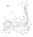
- FIG. 1is a perspective view of an elliptical exercise machine
- FIG. 2is a first side view of the elliptical machine shown in FIG. 1 ;
- FIG. 3is side view of an elliptical machine according to another embodiment
- FIG. 4is a side view of the elliptical machine shown in FIGS. 1 and 2 while in a stowed or stored position;
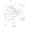
- FIG. 5is an enlarged detail view of certain portions the elliptical machine as shown in FIG. 4 ;
- FIG. 6is a partial cross-sectional view of a portion of the elliptical machine.
- the elliptical exercise machine 100includes a first assembly 102 operatively coupled with a second assembly 104 .
- the first assembly 102includes a longitudinal frame member 106 coupled with a first foot or cross member 108 and a second foot or cross member 110 .
- a rear drive/resistance mechanism 112(referred to herein as the rear mechanism 112 for convenience) is coupled with the frame member 106 and may include, for example, a flywheel and a resistance mechanism as will be appreciated by those of ordinary skill in the art.
- the resistance mechanismmay include a magnetic braking mechanism, sometimes referred to as an eddy current brake, to provide a desired level of resistance to the user during operation of the exercise machine 100 . While described in connection with an exercise bicycle, one example of a flywheel, as well as an associated magnetic braking mechanism, is described by U.S. Patent Application Publication No. 2012/0088638 to Lull (application Ser. No. 13/267,719), the disclosure of which is incorporated by reference herein in its entirety.
- the lower assembly 102further includes a first reciprocating foot support 114 and a second reciprocating foot support 116 .
- the first foot support 114has a first end 118 and a second end 120 , the second end 120 being pivotally coupled with the rear mechanism 112 such that the second end 120 of the foot support 114 travels in a substantially circular path during operation of the elliptical machine 100 .
- a foot pad 122is disposed on the first foot support at a location between the first end 118 and the second end 120 .
- the foot pad 122is sized and configured to receive and support a foot of a user and may either be integrally formed with the foot support 114 or formed as a separate component and coupled with the foot support 114 (e.g., by fasteners, adhesive, or other mechanical or material techniques).
- the second reciprocating foot support 116likewise includes a first end 124 and a second end 126 , with the second end 126 being pivotally coupled with the rear mechanism 112 such that the second end 126 of the foot support 116 travels in a substantially circular path during operation of the elliptical machine 100 .
- a second foot pad 128is disposed on the second foot support 116 at a location between the first end 124 and the second end 126 .
- the first and second reciprocating foot supports 114 and 116are laterally spaced apart from one another such that each of the corresponding foot pads 122 and 128 receive the right and left feet, respectively, of a user for facilitating a striding motion with the user during use of the machine 100 .
- the foot pads 122 and 128may be configured with surface features (e.g., ribs, grooves, knobs, etc) to provide traction to the foot of a user. In other embodiments, while the foot pads may not necessarily include surface features, they may include a non-slip material to provide traction to the foot of a user.
- the foot pads 122 and 128may be adjustable relative to their associated foot supports 114 and 116 such that they may be positioned at different locations along the lengths of the foot supports 114 and 116 to accommodate the preferences of different users.
- the first assembly 102may include a number of additional components or features.
- a handle 130may be coupled with front cross member 108 to assist in lifting or moving the elliptical machine 100 .
- Additional handlesmay be coupled to other portions of the elliptical machine 100 to further enable a user to more easily lift or move the elliptical machine 100 .
- One or more wheels 132may be coupled to the rear cross member 110 to enable a user to more easily move the elliptical machine 100 from one location to another by, for example, lifting on the front handle 130 and rolling the elliptical machine 100 across the floor.
- feet or support pads 134may be coupled to various portions of the first assembly 102 and may be configured to engage the floor or a supporting surface. The support pads 134 may be adjustable so that the elliptical machine 100 may be leveled on a given surface prior to operation by a user.
- the second assembly 104includes an upright frame member 140 with a control panel 142 coupled therewith.
- the control panel 142may include a variety of input devices 144 (e.g., switches, buttons, touch pads) and output devices 146 (e.g., graphic displays, lights, audio speakers) to facilitate control of the elliptical machine 100 .
- the input devices 144may be used to turn the elliptical machine 100 on or off, to control the amount of resistance being applied to the flywheel of the rear mechanism 112 , to enable preset exercise programs, or to otherwise control the operation of the elliptical machine.
- the various output devices 146may be used to provide a user with an indication of the operating status of the elliptical machine 100 and to provide other information (e.g., time exercised, calories burned, etc.) to the user.
- a tray 148which may include a cup holder or other structure, may be coupled with the frame member 140 .
- a pair of stationary hand grips 150may be coupled with the upright frame member 140 .
- other componentssuch as a fan, may also be coupled with the frame member 140 as will be recognized by those of ordinary skill in the art.
- the second assembly 104also includes a first reciprocating arm 152 and second reciprocating arm 154 .
- the first reciprocating arm 152includes a first end 156 and a second end 158 .
- the second reciprocating arm 154includes a first end 160 and a second end 162 .
- Upper portions of the reciprocating arms 152 and 154 near the first ends 156 and 160are configured as grips or handles for a user to grasp with their hands while exercising.
- the second ends 158 and 162 of the reciprocating arms 152 and 154are pivotally coupled with the first ends 118 and 124 of the foot support members.
- Each of the reciprocating arms 152 and 154are pivotally coupled to the frame member 140 through associated pivoting structures 164 .
- the pivoting structures 164may include, for example, a bearing member that enables the reciprocating arms to pivot back and forth along an axis of rotation 166 in a reciprocating fashion.
- a userplaces their feet on the foot pads 122 and 128 and applies a force in order to motivate the foot supports 114 and 116 to move through their defined looping pathways.
- the pathway of the foot supports 114 and 116(and thus the foot pads 122 and 128 ) is defined in part by the connection of the foot supports 114 and 116 with the rear mechanism 112 and in part by the connection of the foot supports 114 and 116 with the reciprocating arms 152 and 154 .
- the longitudinal frame member 106is pivotally coupled with the upright frame member 140 by a pivoting structure 170 .
- the pivoting structure 170may include a bearing component (e.g., a sleeve bearing, a roller bearing, or other appropriate structure) to accommodate pivoting movement of the upright frame member 140 relative to the longitudinal frame member 106 .
- a locking or coupling mechanism 172may be used to affirmatively maintain the frame members 106 and 140 (and, thus, the assemblies 102 and 104 ) in their operating positions as shown in FIGS. 1 and 2 and as will be described in further detail below.
- FIG. 3another embodiment of an elliptical exercise machine 180 is shown.
- the elliptical machineis similar to that shown and described with respect to FIGS. 1 and 2 above, including a first assembly 102 , a second assembly 104 and the various components described above.
- the elliptical machine 180 shown in FIG. 3further includes an incline adjustment mechanism 182 that enables selective height adjustment of the front cross member 108 relative to the rear cross member 110 , thereby altering the angular orientation of the foot supports 114 and 116 and their associated pathways.
- the incline adjustment mechanism 182may include, for example, a pair of arms 184 or links (one shown in FIG. 3 ) pivotally coupled between the front cross member 108 and the longitudinal frame member 106 , as well as an actuator 186 , such as a jackscrew, a pneumatic cylinder, a stepper motor or other appropriate actuating mechanism.
- the elliptical machine 100is shown in a folded or storage position, wherein the second assembly 104 has been rotated about the pivot structure 170 relative to the first assembly 102 such that the upper portion of the second assembly 104 (e.g., the control panel 142 , the hand grips 150 ) are positioned adjacent the rear portion of the first assembly 102 (e.g., the rear mechanism 112 ).
- the embodiment described with respect to FIG. 3is also configured to fold or transition into a collapsed or storage condition in a manner similar to that shown in FIG. 4 . In one embodiment, such folding or collapsing of the elliptical machine 180 shown in FIG.
- the pivoting structure 170 of the elliptical machine 180may be configured to remain in a locked state until the elliptical machined 180 is in a predefined inclination position (e.g., completely lowered to toward the floor or supporting surface).
- FIG. 5an enlarged view of the various components of the elliptical machine 100 are shown in a folded or collapsed state.
- FIG. 5shows the second assembly 104 rotated about the pivot structure 170 relative to the first assembly 102 . It is noted that, when in the position or state shown in FIGS. 4 and 5 , the pivotal axes of the connections between foot supports 114 and 116 and associated reciprocating arms 152 and 154 are aligned with the pivotal axis of the pivot structure 170 which couples the longitudinal frame member 106 and the upright frame member 140 .
- the coupling mechanism 172may include a fastener 190 having a handle or knob 192 coupled therewith enabling a user to rotate the fastener by hand (i.e., without the need for additional tools).
- the fastener 190may be configured to be rotationally coupled with the upright frame member 140 of the second assembly 104 .
- the fastenermay be configured to threadably engage a structure or component of the first assembly 102 .
- a post 194 or other structural componentmay be coupled with the longitudinal frame member 106 and include, for example, a plate 196 through which a threaded aperture is formed.
- the fastener 190may then selectively engage and disengage the threaded aperture in order to either maintain the first and second assemblies 102 and 104 in an operating condition (as shown in FIGS. 1, 2, 3 and 6 ) or to enable relative rotation of the first and second assemblies 102 and 104 so that they may be placed in a stored or collapsed condition (as depicted in FIGS. 4 and 5 ).
- FIG. 5includes a fastener 190 used to affirmatively couple the first assembly 102 and the second assembly 104 in an operating position
- a locking mechanism with a cam surfacemay be used to provide an affirmative coupling.
- Other examplesmay include locking pins that may be inserted in aligned apertures of different components of the first and second assemblies 102 and 104 .
- the upright arm 140 of the second assembly 104is configured such that it does not interfere with the post 194 or plate 196 (or other similar structure) when rotating between an operational position and a collapsed position.
- the upright arm 140is formed from structural tubing (e.g., with a square or rectangular cross-section)
- a portion of the tubingmay be removed, as shown in FIG. 6 , to provide an opening 198 that enables non-interfering rotation of the upright frame member 140 relative to the post 194 and plate 196 .
- a mechanism or structuremay be also be provided to lock the first and second assemblies 102 and 104 in a collapsed position so that, for example, if an individual desires to move the elliptical machine 100 (or 180 ) while it is in the collapsed position, the first and second assemblies 102 and 104 will maintain their positions relative to each other.
- an elliptical machinemay be approximately 24 to 30 inches in width, approximately 76 to 84 inches in length and approximately 62 to 70 inches in height. Some users may not desire to permanently dedicate so much space in their residence to an exercise machine.
- the elliptical machines described hereinprovide the ability to place the machine in a collapsed position or state when not in use so that the elliptical machine may be stored or more easily maneuvered and transported.
- the elliptical machineis configured in two assemblies, which may be referred to as an upper assembly and a lower assembly, wherein the upper assembly pivots and folds down on to or adjacent to the lower assembly without the need to disassemble or otherwise any of the operational components such as the foot supports or the reciprocating arms.
- the upper assemblypivots and folds down on to or adjacent to the lower assembly without the need to disassemble or otherwise any of the operational components such as the foot supports or the reciprocating arms.
- some prior art devicesrequired a “break-away” joint in the foot supports or the reciprocating arms, such that a user would have to disassemble such joints in order to facilitate the folding or collapsing, and then reassemble such joints when the elliptical machine was unfolded or expanded and prior to using the exercise machine again.
- the present designeliminates the possibility of someone trying to use an elliptical machine prior to reassembly of such components, which could possibly result in damage to the machine or injury to the user.
- folding or collapsing of the assemblies in the elliptical machines described hereindoes not require the adjustment of any operative components such as the foot supports or reciprocating arms.
- any operative componentssuch as the foot supports or reciprocating arms.
- PCT Patent Application Publication No. WO2008138124describes a machine wherein the reciprocating arms require adjustment between the operative condition and the stored condition.
- the present inventiondoes not require any adjustment of the reciprocating arms or the foot supports to in transitioning from the operable condition to the stored condition. Rather, the components of the first assembly all maintain their operational relationship to one another and all the components of the second assembly maintain their operational relationship to one another before and after the folding or unfolding of the elliptical machine.
- Such a configurationenables very simple folding and deployment of the elliptical machine by a user since they don't have to adjust any critical components (e.g., foot supports or reciprocating arms) and ensures that the elliptical machine is in a ready immediately after unfolding.
- any critical componentse.g., foot supports or reciprocating arms
- the ability to fold or collapse the elliptical machinefurther provides advantages in moving or transporting the machine when not in use. Besides taking up less space when in a folded state, the elliptical machine is much easier to handle or transport when in the folder state since it is more compact and its center of gravity is more amenable to lifting and maneuvering making it less likely to tip or fall. Furthermore, the ability to fold and unfold the elliptical machine makes it easier to ship or transport in a small package while not requiring assembly after shipping or purchase by the end user.
Landscapes
- Health & Medical Sciences (AREA)
- General Health & Medical Sciences (AREA)
- Physical Education & Sports Medicine (AREA)
- Cardiology (AREA)
- Vascular Medicine (AREA)
- Engineering & Computer Science (AREA)
- Human Computer Interaction (AREA)
- Rehabilitation Tools (AREA)
Abstract
Description
Claims (18)
Priority Applications (1)
| Application Number | Priority Date | Filing Date | Title |
|---|---|---|---|
| US14/303,464US9492704B2 (en) | 2013-06-13 | 2014-06-12 | Folding rear drive elliptical |
Applications Claiming Priority (4)
| Application Number | Priority Date | Filing Date | Title |
|---|---|---|---|
| US201361834711P | 2013-06-13 | 2013-06-13 | |
| US201361834709P | 2013-06-13 | 2013-06-13 | |
| US201361834706P | 2013-06-13 | 2013-06-13 | |
| US14/303,464US9492704B2 (en) | 2013-06-13 | 2014-06-12 | Folding rear drive elliptical |
Publications (2)
| Publication Number | Publication Date |
|---|---|
| US20140371035A1 US20140371035A1 (en) | 2014-12-18 |
| US9492704B2true US9492704B2 (en) | 2016-11-15 |
Family
ID=52019706
Family Applications (1)
| Application Number | Title | Priority Date | Filing Date |
|---|---|---|---|
| US14/303,464Active2034-07-01US9492704B2 (en) | 2013-06-13 | 2014-06-12 | Folding rear drive elliptical |
Country Status (4)
| Country | Link |
|---|---|
| US (1) | US9492704B2 (en) |
| EP (1) | EP3007781B1 (en) |
| CN (1) | CN105407982B (en) |
| WO (1) | WO2014201294A1 (en) |
Cited By (39)
| Publication number | Priority date | Publication date | Assignee | Title |
|---|---|---|---|---|
| US10449416B2 (en) | 2015-08-26 | 2019-10-22 | Icon Health & Fitness, Inc. | Strength exercise mechanisms |
| US10493349B2 (en) | 2016-03-18 | 2019-12-03 | Icon Health & Fitness, Inc. | Display on exercise device |
| US10561894B2 (en) | 2016-03-18 | 2020-02-18 | Icon Health & Fitness, Inc. | Treadmill with removable supports |
| US10625114B2 (en) | 2016-11-01 | 2020-04-21 | Icon Health & Fitness, Inc. | Elliptical and stationary bicycle apparatus including row functionality |
| US10709925B2 (en) | 2013-03-14 | 2020-07-14 | Icon Health & Fitness, Inc. | Strength training apparatus |
| US10758767B2 (en) | 2013-12-26 | 2020-09-01 | Icon Health & Fitness, Inc. | Resistance mechanism in a cable exercise machine |
| US10786706B2 (en) | 2018-07-13 | 2020-09-29 | Icon Health & Fitness, Inc. | Cycling shoe power sensors |
| US10864407B2 (en) | 2016-03-18 | 2020-12-15 | Icon Health & Fitness, Inc. | Coordinated weight selection |
| US10918905B2 (en) | 2016-10-12 | 2021-02-16 | Icon Health & Fitness, Inc. | Systems and methods for reducing runaway resistance on an exercise device |
| US10932517B2 (en) | 2014-03-10 | 2021-03-02 | Icon Health & Fitness, Inc. | Pressure sensor to quantify work |
| US10940360B2 (en) | 2015-08-26 | 2021-03-09 | Icon Health & Fitness, Inc. | Strength exercise mechanisms |
| US10953305B2 (en) | 2015-08-26 | 2021-03-23 | Icon Health & Fitness, Inc. | Strength exercise mechanisms |
| US10994173B2 (en) | 2016-05-13 | 2021-05-04 | Icon Health & Fitness, Inc. | Weight platform treadmill |
| US11000730B2 (en) | 2018-03-16 | 2021-05-11 | Icon Health & Fitness, Inc. | Elliptical exercise machine |
| US11033777B1 (en) | 2019-02-12 | 2021-06-15 | Icon Health & Fitness, Inc. | Stationary exercise machine |
| US11058913B2 (en) | 2017-12-22 | 2021-07-13 | Icon Health & Fitness, Inc. | Inclinable exercise machine |
| US11058914B2 (en) | 2016-07-01 | 2021-07-13 | Icon Health & Fitness, Inc. | Cooling methods for exercise equipment |
| US11187285B2 (en) | 2017-12-09 | 2021-11-30 | Icon Health & Fitness, Inc. | Systems and methods for selectively rotationally fixing a pedaled drivetrain |
| US11298577B2 (en) | 2019-02-11 | 2022-04-12 | Ifit Inc. | Cable and power rack exercise machine |
| US11326673B2 (en) | 2018-06-11 | 2022-05-10 | Ifit Inc. | Increased durability linear actuator |
| US11451108B2 (en) | 2017-08-16 | 2022-09-20 | Ifit Inc. | Systems and methods for axial impact resistance in electric motors |
| US11534651B2 (en) | 2019-08-15 | 2022-12-27 | Ifit Inc. | Adjustable dumbbell system |
| US11534654B2 (en) | 2019-01-25 | 2022-12-27 | Ifit Inc. | Systems and methods for an interactive pedaled exercise device |
| US11673036B2 (en) | 2019-11-12 | 2023-06-13 | Ifit Inc. | Exercise storage system |
| US11794070B2 (en) | 2019-05-23 | 2023-10-24 | Ifit Inc. | Systems and methods for cooling an exercise device |
| US11850497B2 (en) | 2019-10-11 | 2023-12-26 | Ifit Inc. | Modular exercise device |
| US11878199B2 (en) | 2021-02-16 | 2024-01-23 | Ifit Inc. | Safety mechanism for an adjustable dumbbell |
| US11931621B2 (en) | 2020-03-18 | 2024-03-19 | Ifit Inc. | Systems and methods for treadmill drift avoidance |
| US11951377B2 (en) | 2020-03-24 | 2024-04-09 | Ifit Inc. | Leaderboard with irregularity flags in an exercise machine system |
| US12029935B2 (en) | 2021-08-19 | 2024-07-09 | Ifit Inc. | Adjustment mechanism for an adjustable kettlebell |
| US12029961B2 (en) | 2020-03-24 | 2024-07-09 | Ifit Inc. | Flagging irregularities in user performance in an exercise machine system |
| US12176009B2 (en) | 2021-12-30 | 2024-12-24 | Ifit Inc. | Systems and methods for synchronizing workout equipment with video files |
| US12219201B2 (en) | 2021-08-05 | 2025-02-04 | Ifit Inc. | Synchronizing video workout programs across multiple devices |
| US12263371B2 (en) | 2021-04-27 | 2025-04-01 | Ifit Inc. | Devices, systems, and methods for rotating a tread belt in two directions |
| US12280294B2 (en) | 2021-10-15 | 2025-04-22 | Ifit Inc. | Magnetic clutch for a pedaled drivetrain |
| US12350573B2 (en) | 2021-04-27 | 2025-07-08 | Ifit Inc. | Systems and methods for cross-training on exercise devices |
| US12350547B2 (en) | 2022-02-28 | 2025-07-08 | Ifit Inc. | Devices, systems, and methods for moving a movable step through a transition zone |
| US12409375B2 (en) | 2022-03-18 | 2025-09-09 | Ifit Inc. | Systems and methods for haptic simulation in incline exercise devices |
| US12433815B2 (en) | 2020-10-02 | 2025-10-07 | Ifit Inc. | Massage roller with pressure sensors |
Families Citing this family (15)
| Publication number | Priority date | Publication date | Assignee | Title |
|---|---|---|---|---|
| US9345948B2 (en) | 2012-10-19 | 2016-05-24 | Todd Martin | System for providing a coach with live training data of an athlete as the athlete is training |
| WO2014201288A1 (en) | 2013-06-13 | 2014-12-18 | Icon Health & Fitness, Inc. | Folding elliptical lift assist system |
| USD827732S1 (en)* | 2016-06-24 | 2018-09-04 | Wei-Teh Ho | Stepper exercise machine |
| US9925411B2 (en) | 2015-11-06 | 2018-03-27 | Dyaco International Inc. | Exercise machine having a hubless rotary mechanism |
| US10625137B2 (en) | 2016-03-18 | 2020-04-21 | Icon Health & Fitness, Inc. | Coordinated displays in an exercise device |
| US10441840B2 (en)* | 2016-03-18 | 2019-10-15 | Icon Health & Fitness, Inc. | Collapsible strength exercise machine |
| USD801454S1 (en)* | 2016-10-24 | 2017-10-31 | Precor Incorporated | Rear housing of an exercise device |
| USD801451S1 (en)* | 2016-10-24 | 2017-10-31 | Precor Incorporated | Exercise device |
| TWI648081B (en) | 2016-12-05 | 2019-01-21 | 美商愛康運動與健康公司 | Pull rope resistance mechanism in treadmill |
| TWI672164B (en) | 2016-12-05 | 2019-09-21 | 美商愛康運動與健康公司 | Tread belt locking mechanism |
| USD843502S1 (en)* | 2017-04-05 | 2019-03-19 | Jackson Hsieh | Elliptical stepper exercise machine |
| USD853503S1 (en)* | 2017-06-27 | 2019-07-09 | Kai Bin Xing | Exercise device |
| USD854100S1 (en)* | 2017-06-27 | 2019-07-16 | Kai Bin Xing | Exercise device |
| USD1085286S1 (en)* | 2024-04-16 | 2025-07-22 | Zheng Xing (Tongxiang) Health Technology Co., Ltd. | Elliptical machine |
| USD1080771S1 (en)* | 2024-07-11 | 2025-06-24 | Hangzhou Xinyuan Electronic Technology Co., Ltd. | Elliptical machine |
Citations (14)
| Publication number | Priority date | Publication date | Assignee | Title |
|---|---|---|---|---|
| US5746683A (en)* | 1997-07-16 | 1998-05-05 | Lee; Kuo-Lung | Folding collapsible step exercising machine |
| US5755643A (en)* | 1997-07-02 | 1998-05-26 | Sands; Lenny | Folding collapsible step exerciser with damping means |
| US5782722A (en)* | 1997-08-27 | 1998-07-21 | Sands; Lenny | Structure of folding collapsible step exerciser |
| US5860895A (en)* | 1997-11-06 | 1999-01-19 | Lee; Kuo-Lung | Structure of folding collapsible step exercising machine |
| WO1999058204A1 (en) | 1998-05-12 | 1999-11-18 | Epix, Inc. | Foldable elliptical exercise machine |
| US6030320A (en)* | 1998-01-12 | 2000-02-29 | Stearns; Kenneth W. | Collapsible exercise apparatus |
| US20080280733A1 (en)* | 2007-05-09 | 2008-11-13 | Spark Innovations, Inc. | Folding elliptical exercise machine |
| US7462135B2 (en)* | 2005-09-09 | 2008-12-09 | Chiu-Hsiang Lo | Elliptical fitness machine having incline adjusting mechanism |
| US20100167880A1 (en) | 2006-08-02 | 2010-07-01 | Johnson Health Tech Co., Ltd. | Exercise apparatus |
| US7775940B2 (en) | 2004-08-11 | 2010-08-17 | Icon Ip, Inc. | Folding elliptical exercise machine |
| US20100242246A1 (en)* | 2007-02-20 | 2010-09-30 | Icon Ip, Inc. | One-step foldable elliptical exercise machine |
| CN201815049U (en) | 2010-07-02 | 2011-05-04 | 东莞市鑫源健身器材有限公司 | A treadmill with a fully foldable structure |
| US20120088638A1 (en) | 2010-10-06 | 2012-04-12 | Lull Andrew P | Exercise bicycle with magnetic flywheel brake |
| US8663070B2 (en)* | 2009-08-13 | 2014-03-04 | Johnson Health Tech Co., Ltd. | Elliptical exercise apparatus |
Family Cites Families (5)
| Publication number | Priority date | Publication date | Assignee | Title |
|---|---|---|---|---|
| DE29720158U1 (en)* | 1997-11-13 | 1998-01-02 | Kuo, Johnson, Taipeh/T'ai-pei | Collapsible walking training device |
| DE29802816U1 (en)* | 1998-02-18 | 1998-04-23 | Chen, Chao-Chuan, Wu Feng, Taichung | Exercise device |
| US6135927A (en)* | 1999-10-29 | 2000-10-24 | Lo; Kun-Chuan | Foldable exerciser |
| TWM287691U (en)* | 2005-09-09 | 2006-02-21 | Chiu-Hsiang Lo | Ellipse exercise machine with all-foldable function |
| US7507186B2 (en)* | 2007-03-14 | 2009-03-24 | Stearns Kenneth W | Exercise methods and apparatus with elliptical foot motion |
- 2014
- 2014-06-12EPEP14811051.3Apatent/EP3007781B1/enactiveActive
- 2014-06-12WOPCT/US2014/042189patent/WO2014201294A1/enactiveApplication Filing
- 2014-06-12USUS14/303,464patent/US9492704B2/enactiveActive
- 2014-06-12CNCN201480042089.6Apatent/CN105407982B/enactiveActive
Patent Citations (17)
| Publication number | Priority date | Publication date | Assignee | Title |
|---|---|---|---|---|
| US5755643A (en)* | 1997-07-02 | 1998-05-26 | Sands; Lenny | Folding collapsible step exerciser with damping means |
| US5746683A (en)* | 1997-07-16 | 1998-05-05 | Lee; Kuo-Lung | Folding collapsible step exercising machine |
| US5782722A (en)* | 1997-08-27 | 1998-07-21 | Sands; Lenny | Structure of folding collapsible step exerciser |
| US5860895A (en)* | 1997-11-06 | 1999-01-19 | Lee; Kuo-Lung | Structure of folding collapsible step exercising machine |
| US6030320A (en)* | 1998-01-12 | 2000-02-29 | Stearns; Kenneth W. | Collapsible exercise apparatus |
| WO1999058204A1 (en) | 1998-05-12 | 1999-11-18 | Epix, Inc. | Foldable elliptical exercise machine |
| US6149551A (en)* | 1998-05-12 | 2000-11-21 | Epix, Inc. | Foldable elliptical exercise machine |
| US6190289B1 (en) | 1998-05-12 | 2001-02-20 | Epix, Inc. | Foldable elliptical exercise machine |
| US7775940B2 (en) | 2004-08-11 | 2010-08-17 | Icon Ip, Inc. | Folding elliptical exercise machine |
| US7462135B2 (en)* | 2005-09-09 | 2008-12-09 | Chiu-Hsiang Lo | Elliptical fitness machine having incline adjusting mechanism |
| US20100167880A1 (en) | 2006-08-02 | 2010-07-01 | Johnson Health Tech Co., Ltd. | Exercise apparatus |
| US20100242246A1 (en)* | 2007-02-20 | 2010-09-30 | Icon Ip, Inc. | One-step foldable elliptical exercise machine |
| WO2008138124A1 (en) | 2007-05-09 | 2008-11-20 | Spark Innovations, Inc. | Folding elliptical exercise machine |
| US20080280733A1 (en)* | 2007-05-09 | 2008-11-13 | Spark Innovations, Inc. | Folding elliptical exercise machine |
| US8663070B2 (en)* | 2009-08-13 | 2014-03-04 | Johnson Health Tech Co., Ltd. | Elliptical exercise apparatus |
| CN201815049U (en) | 2010-07-02 | 2011-05-04 | 东莞市鑫源健身器材有限公司 | A treadmill with a fully foldable structure |
| US20120088638A1 (en) | 2010-10-06 | 2012-04-12 | Lull Andrew P | Exercise bicycle with magnetic flywheel brake |
Non-Patent Citations (4)
| Title |
|---|
| English Machine Translation of claim 1 of CN 201815049 published on May 4, 2011. |
| Icon Health & Fitness, U.S. Appl. No. 14/303,451, filed Jun. 12, 2014. |
| Icon Health & Fitness, U.S. Appl. No. 14/303,459, filed Jun. 12, 2014. |
| International Search Report issued for PCT/US2014/042179 on Oct. 10, 2014. |
Cited By (63)
| Publication number | Priority date | Publication date | Assignee | Title |
|---|---|---|---|---|
| US11338169B2 (en) | 2013-03-14 | 2022-05-24 | IFIT, Inc. | Strength training apparatus |
| US11878206B2 (en) | 2013-03-14 | 2024-01-23 | Ifit Inc. | Strength training apparatus |
| US10953268B1 (en) | 2013-03-14 | 2021-03-23 | Icon Health & Fitness, Inc. | Strength training apparatus |
| US10709925B2 (en) | 2013-03-14 | 2020-07-14 | Icon Health & Fitness, Inc. | Strength training apparatus |
| US10967214B1 (en) | 2013-12-26 | 2021-04-06 | Icon Health & Fitness, Inc. | Cable exercise machine |
| US10758767B2 (en) | 2013-12-26 | 2020-09-01 | Icon Health & Fitness, Inc. | Resistance mechanism in a cable exercise machine |
| US11700905B2 (en) | 2014-03-10 | 2023-07-18 | Ifit Inc. | Pressure sensor to quantify work |
| US10932517B2 (en) | 2014-03-10 | 2021-03-02 | Icon Health & Fitness, Inc. | Pressure sensor to quantify work |
| US10940360B2 (en) | 2015-08-26 | 2021-03-09 | Icon Health & Fitness, Inc. | Strength exercise mechanisms |
| US10953305B2 (en) | 2015-08-26 | 2021-03-23 | Icon Health & Fitness, Inc. | Strength exercise mechanisms |
| US10449416B2 (en) | 2015-08-26 | 2019-10-22 | Icon Health & Fitness, Inc. | Strength exercise mechanisms |
| US10864407B2 (en) | 2016-03-18 | 2020-12-15 | Icon Health & Fitness, Inc. | Coordinated weight selection |
| US12023549B2 (en) | 2016-03-18 | 2024-07-02 | Ifit Inc. | Stationary exercise machine configured to execute a programmed workout with aerobic portions and lifting portions |
| US11565148B2 (en) | 2016-03-18 | 2023-01-31 | Ifit Inc. | Treadmill with a scale mechanism in a motor cover |
| US10561894B2 (en) | 2016-03-18 | 2020-02-18 | Icon Health & Fitness, Inc. | Treadmill with removable supports |
| US12029944B2 (en) | 2016-03-18 | 2024-07-09 | Ifit Inc. | Stationary exercise machine configured to execute a programmed workout with aerobic portions and lifting portions |
| US11013960B2 (en) | 2016-03-18 | 2021-05-25 | Icon Health & Fitness, Inc. | Exercise system including a stationary bicycle and a free weight cradle |
| US12029943B2 (en) | 2016-03-18 | 2024-07-09 | Ifit Inc. | Stationary exercise machine configured to execute a programmed workout with aerobic portions and lifting portions |
| US11794075B2 (en) | 2016-03-18 | 2023-10-24 | Ifit Inc. | Stationary exercise machine configured to execute a programmed workout with aerobic portions and lifting portions |
| US10493349B2 (en) | 2016-03-18 | 2019-12-03 | Icon Health & Fitness, Inc. | Display on exercise device |
| US10994173B2 (en) | 2016-05-13 | 2021-05-04 | Icon Health & Fitness, Inc. | Weight platform treadmill |
| US11779812B2 (en) | 2016-05-13 | 2023-10-10 | Ifit Inc. | Treadmill configured to automatically determine user exercise movement |
| US11058914B2 (en) | 2016-07-01 | 2021-07-13 | Icon Health & Fitness, Inc. | Cooling methods for exercise equipment |
| US10918905B2 (en) | 2016-10-12 | 2021-02-16 | Icon Health & Fitness, Inc. | Systems and methods for reducing runaway resistance on an exercise device |
| US10625114B2 (en) | 2016-11-01 | 2020-04-21 | Icon Health & Fitness, Inc. | Elliptical and stationary bicycle apparatus including row functionality |
| US11451108B2 (en) | 2017-08-16 | 2022-09-20 | Ifit Inc. | Systems and methods for axial impact resistance in electric motors |
| US11187285B2 (en) | 2017-12-09 | 2021-11-30 | Icon Health & Fitness, Inc. | Systems and methods for selectively rotationally fixing a pedaled drivetrain |
| US11708874B2 (en) | 2017-12-09 | 2023-07-25 | Ifit Inc. | Systems and methods for selectively rotationally fixing a pedaled drivetrain |
| US12270441B2 (en) | 2017-12-09 | 2025-04-08 | Ifit Inc. | Systems and methods for selectively rotationally fixing a pedaled drivetrain |
| US11680611B2 (en) | 2017-12-09 | 2023-06-20 | Ifit Inc. | Systems and methods for selectively rotationally fixing a pedaled drivetrain |
| US11058913B2 (en) | 2017-12-22 | 2021-07-13 | Icon Health & Fitness, Inc. | Inclinable exercise machine |
| US11596830B2 (en) | 2018-03-16 | 2023-03-07 | Ifit Inc. | Elliptical exercise machine |
| US11000730B2 (en) | 2018-03-16 | 2021-05-11 | Icon Health & Fitness, Inc. | Elliptical exercise machine |
| US11326673B2 (en) | 2018-06-11 | 2022-05-10 | Ifit Inc. | Increased durability linear actuator |
| US10786706B2 (en) | 2018-07-13 | 2020-09-29 | Icon Health & Fitness, Inc. | Cycling shoe power sensors |
| US12005315B2 (en) | 2018-07-13 | 2024-06-11 | Ifit Inc. | Cycling shoe power sensors |
| US11534654B2 (en) | 2019-01-25 | 2022-12-27 | Ifit Inc. | Systems and methods for an interactive pedaled exercise device |
| US11452903B2 (en) | 2019-02-11 | 2022-09-27 | Ifit Inc. | Exercise machine |
| US11642564B2 (en) | 2019-02-11 | 2023-05-09 | Ifit Inc. | Exercise machine |
| US11298577B2 (en) | 2019-02-11 | 2022-04-12 | Ifit Inc. | Cable and power rack exercise machine |
| US11951358B2 (en) | 2019-02-12 | 2024-04-09 | Ifit Inc. | Encoding exercise machine control commands in subtitle streams |
| US11426633B2 (en) | 2019-02-12 | 2022-08-30 | Ifit Inc. | Controlling an exercise machine using a video workout program |
| US11033777B1 (en) | 2019-02-12 | 2021-06-15 | Icon Health & Fitness, Inc. | Stationary exercise machine |
| US11058918B1 (en) | 2019-02-12 | 2021-07-13 | Icon Health & Fitness, Inc. | Producing a workout video to control a stationary exercise machine |
| US11794070B2 (en) | 2019-05-23 | 2023-10-24 | Ifit Inc. | Systems and methods for cooling an exercise device |
| US11534651B2 (en) | 2019-08-15 | 2022-12-27 | Ifit Inc. | Adjustable dumbbell system |
| US12296247B2 (en) | 2019-10-11 | 2025-05-13 | Ifit Inc. | Modular exercise device |
| US11850497B2 (en) | 2019-10-11 | 2023-12-26 | Ifit Inc. | Modular exercise device |
| US11673036B2 (en) | 2019-11-12 | 2023-06-13 | Ifit Inc. | Exercise storage system |
| US11931621B2 (en) | 2020-03-18 | 2024-03-19 | Ifit Inc. | Systems and methods for treadmill drift avoidance |
| US12029961B2 (en) | 2020-03-24 | 2024-07-09 | Ifit Inc. | Flagging irregularities in user performance in an exercise machine system |
| US11951377B2 (en) | 2020-03-24 | 2024-04-09 | Ifit Inc. | Leaderboard with irregularity flags in an exercise machine system |
| US12433815B2 (en) | 2020-10-02 | 2025-10-07 | Ifit Inc. | Massage roller with pressure sensors |
| US11878199B2 (en) | 2021-02-16 | 2024-01-23 | Ifit Inc. | Safety mechanism for an adjustable dumbbell |
| US12239872B2 (en) | 2021-02-16 | 2025-03-04 | Ifit Inc. | Safety mechanism for an adjustable dumbbell |
| US12350573B2 (en) | 2021-04-27 | 2025-07-08 | Ifit Inc. | Systems and methods for cross-training on exercise devices |
| US12263371B2 (en) | 2021-04-27 | 2025-04-01 | Ifit Inc. | Devices, systems, and methods for rotating a tread belt in two directions |
| US12219201B2 (en) | 2021-08-05 | 2025-02-04 | Ifit Inc. | Synchronizing video workout programs across multiple devices |
| US12029935B2 (en) | 2021-08-19 | 2024-07-09 | Ifit Inc. | Adjustment mechanism for an adjustable kettlebell |
| US12280294B2 (en) | 2021-10-15 | 2025-04-22 | Ifit Inc. | Magnetic clutch for a pedaled drivetrain |
| US12176009B2 (en) | 2021-12-30 | 2024-12-24 | Ifit Inc. | Systems and methods for synchronizing workout equipment with video files |
| US12350547B2 (en) | 2022-02-28 | 2025-07-08 | Ifit Inc. | Devices, systems, and methods for moving a movable step through a transition zone |
| US12409375B2 (en) | 2022-03-18 | 2025-09-09 | Ifit Inc. | Systems and methods for haptic simulation in incline exercise devices |
Also Published As
| Publication number | Publication date |
|---|---|
| CN105407982A (en) | 2016-03-16 |
| US20140371035A1 (en) | 2014-12-18 |
| EP3007781A4 (en) | 2017-01-25 |
| EP3007781B1 (en) | 2019-12-25 |
| EP3007781A1 (en) | 2016-04-20 |
| WO2014201294A1 (en) | 2014-12-18 |
| CN105407982B (en) | 2018-06-19 |
Similar Documents
| Publication | Publication Date | Title |
|---|---|---|
| US9492704B2 (en) | Folding rear drive elliptical | |
| US9937379B2 (en) | Folding elliptical lift assist system | |
| US9421416B2 (en) | Folding elliptical stabilization system | |
| CN106061563B (en) | Low profile collapsible treadmill | |
| US6350218B1 (en) | Fold-out treadmill | |
| CN101203281B (en) | Breakaway or folding elliptical exercise machine | |
| US7736279B2 (en) | One-step foldable elliptical exercise machine | |
| US6068579A (en) | Treadmill with a Y-shaped yoke | |
| US7462135B2 (en) | Elliptical fitness machine having incline adjusting mechanism | |
| US10549145B2 (en) | Stationary exercise apparatus with variable foot path | |
| US11154739B2 (en) | Plyometric exercise ladder | |
| US20070060449A1 (en) | Foldable elliptical fitness machine | |
| US20170106236A1 (en) | Push-up exercise apparatus | |
| WO2008106057A2 (en) | Collapsible and storable apparatus for exercising core muscles | |
| TWI877086B (en) | Multi-functional fitness equipment support structure | |
| CN208018042U (en) | fitness equipment | |
| TWM631458U (en) | Foldable elliptical trainer | |
| CA3045654A1 (en) | Plyometric exercise ladder |
Legal Events
| Date | Code | Title | Description |
|---|---|---|---|
| AS | Assignment | Owner name:ICON HEALTH & FITNESS, INC., UTAH Free format text:ASSIGNMENT OF ASSIGNORS INTEREST;ASSIGNORS:MORTENSEN, NATHAN;DALEBOUT, WILLIAM T.;LARSEN, TRENTON VON;REEL/FRAME:033990/0574 Effective date:20141010 | |
| AS | Assignment | Owner name:BANK OF AMERICA, N.A., AS ADMINISTRATIVE AGENT, MA Free format text:SECURITY AGREEMENT;ASSIGNORS:ICON HEALTH & FITNESS, INC.;ICON IP, INC.;REEL/FRAME:036104/0833 Effective date:20150710 | |
| AS | Assignment | Owner name:ICON - ALTRA LLC, UTAH Free format text:RELEASE OF SECURITY INTEREST IN PATENTS;ASSIGNOR:BANK OF AMERICA, N.A., ACTING IN ITS CAPACITY AS AGENT FOR THE LENDERS;REEL/FRAME:039584/0575 Effective date:20160803 Owner name:HF HOLDINGS, INC., UTAH Free format text:RELEASE OF SECURITY INTEREST IN PATENTS;ASSIGNOR:BANK OF AMERICA, N.A., ACTING IN ITS CAPACITY AS AGENT FOR THE LENDERS;REEL/FRAME:039584/0575 Effective date:20160803 Owner name:UNIVERSAL TECHNICAL SERVICES, UTAH Free format text:RELEASE OF SECURITY INTEREST IN PATENTS;ASSIGNOR:BANK OF AMERICA, N.A., ACTING IN ITS CAPACITY AS AGENT FOR THE LENDERS;REEL/FRAME:039584/0575 Effective date:20160803 Owner name:FREE MOTION FITNESS, INC., UTAH Free format text:RELEASE OF SECURITY INTEREST IN PATENTS;ASSIGNOR:BANK OF AMERICA, N.A., ACTING IN ITS CAPACITY AS AGENT FOR THE LENDERS;REEL/FRAME:039584/0575 Effective date:20160803 Owner name:ICON IP, INC., UTAH Free format text:RELEASE OF SECURITY INTEREST IN PATENTS;ASSIGNOR:BANK OF AMERICA, N.A., ACTING IN ITS CAPACITY AS AGENT FOR THE LENDERS;REEL/FRAME:039584/0575 Effective date:20160803 Owner name:ICON INTERNATIONAL HOLDINGS, INC., UTAH Free format text:RELEASE OF SECURITY INTEREST IN PATENTS;ASSIGNOR:BANK OF AMERICA, N.A., ACTING IN ITS CAPACITY AS AGENT FOR THE LENDERS;REEL/FRAME:039584/0575 Effective date:20160803 Owner name:ICON DU CANADA INC., CANADA Free format text:RELEASE OF SECURITY INTEREST IN PATENTS;ASSIGNOR:BANK OF AMERICA, N.A., ACTING IN ITS CAPACITY AS AGENT FOR THE LENDERS;REEL/FRAME:039584/0575 Effective date:20160803 Owner name:ICON HEALTH & FITNESS, INC, UTAH Free format text:RELEASE OF SECURITY INTEREST IN PATENTS;ASSIGNOR:BANK OF AMERICA, N.A., ACTING IN ITS CAPACITY AS AGENT FOR THE LENDERS;REEL/FRAME:039584/0575 Effective date:20160803 | |
| AS | Assignment | Owner name:JPMORGAN CHASE BANK, N.A., AS ADMINISTRATIVE AGENT Free format text:PATENT SECURITY AGREEMENT;ASSIGNORS:ICON HEALTH FITNESS, INC.;HF HOLDINGS, INC.;UNIVERSAL TECHNICAL SERVICES;AND OTHERS;REEL/FRAME:039669/0311 Effective date:20160803 Owner name:JPMORGAN CHASE BANK, N.A., AS ADMINISTRATIVE AGENT Free format text:PATENT SECURITY AGREEMENT;ASSIGNORS:ICON HEALTH & FITNESS, INC.;HF HOLDINGS, INC.;UNIVERSAL TECHNICAL SERVICES;AND OTHERS;REEL/FRAME:039669/0311 Effective date:20160803 | |
| STCF | Information on status: patent grant | Free format text:PATENTED CASE | |
| MAFP | Maintenance fee payment | Free format text:PAYMENT OF MAINTENANCE FEE, 4TH YEAR, LARGE ENTITY (ORIGINAL EVENT CODE: M1551); ENTITY STATUS OF PATENT OWNER: LARGE ENTITY Year of fee payment:4 | |
| AS | Assignment | Owner name:ICON HEALTH & FITNESS, INC., UTAH Free format text:TERMINATION AND RELEASE OF SECURITY INTEREST IN PATENT RIGHTS;ASSIGNOR:JPMORGAN CHASE BANK, N.A., AS ADMINISTRATIVE AGENT;REEL/FRAME:052671/0737 Effective date:20200427 Owner name:ICON IP, INC., UTAH Free format text:TERMINATION AND RELEASE OF SECURITY INTEREST IN PATENT RIGHTS;ASSIGNOR:JPMORGAN CHASE BANK, N.A., AS ADMINISTRATIVE AGENT;REEL/FRAME:052671/0737 Effective date:20200427 Owner name:JPMORGAN CHASE BANK, N.A., AS ADMINISTRATIVE AGENT, ILLINOIS Free format text:PATENT SECURITY AGREEMENT;ASSIGNOR:ICON HEALTH & FITNESS, INC.;REEL/FRAME:053548/0453 Effective date:20200427 | |
| AS | Assignment | Owner name:BANK OF AMERICA, N.A., AS ADMINISTRATIVE AGENT, CALIFORNIA Free format text:SECURITY INTEREST;ASSIGNOR:ICON HEALTH & FITNESS, INC.;REEL/FRAME:056238/0818 Effective date:20210512 | |
| AS | Assignment | Owner name:ICON HEALTH & FITNESS, INC., UTAH Free format text:TERMINATION AND RELEASE OF SECURITY INTEREST IN PATENTS;ASSIGNOR:JPMORGAN CHASE BANK, N.A., AS ADMINISTRATIVE AGENT;REEL/FRAME:056654/0951 Effective date:20210512 | |
| AS | Assignment | Owner name:IFIT INC, UTAH Free format text:CHANGE OF NAME;ASSIGNOR:ICON HEALTH & FITNESS, INC.;REEL/FRAME:058742/0476 Effective date:20210809 | |
| AS | Assignment | Owner name:IFIT INC., UTAH Free format text:TO CORRECT AN ERROR IN A COVER SHEET PREVIOUSLY RECORDED AT REEL/FRAME 058742/0476 - CORRECT ASSIGNEE NAME IFIT INC TO IFIT INC;ASSIGNOR:ICON HEALTH & FITNESS, INC.;REEL/FRAME:058957/0531 Effective date:20210809 | |
| AS | Assignment | Owner name:PLC AGENT LLC, MASSACHUSETTS Free format text:SECURITY INTEREST;ASSIGNOR:IFIT INC.;REEL/FRAME:059249/0466 Effective date:20220224 | |
| AS | Assignment | Owner name:ICON PREFERRED HOLDINGS, L.P., UTAH Free format text:INTELLECTUAL PROPERTY SECURITY AGREEMENT;ASSIGNOR:IFIT INC.;REEL/FRAME:059633/0313 Effective date:20220224 | |
| AS | Assignment | Owner name:ICON PREFERRED HOLDINGS, L.P., NEW YORK Free format text:CORRECTIVE ASSIGNMENT TO CORRECT THE THE ASSIGNEE'S ADDRESS PREVIOUSLY RECORDED AT REEL: 059633 FRAME: 0313. ASSIGNOR(S) HEREBY CONFIRMS THE ASSIGNMENT;ASSIGNOR:IFIT INC.;REEL/FRAME:060512/0315 Effective date:20220224 | |
| AS | Assignment | Owner name:LC9 CONNECTED HOLDINGS, LP, CONNECTICUT Free format text:SECURITY INTEREST;ASSIGNORS:IFIT INC.;ICON IP, INC.;REEL/FRAME:059857/0830 Effective date:20220224 | |
| AS | Assignment | Owner name:LC9 CONNECTED HOLDINGS, LP, CONNECTICUT Free format text:SECURITY INTEREST;ASSIGNORS:IFIT INC.;ICON IP, INC.;REEL/FRAME:066094/0529 Effective date:20231214 | |
| MAFP | Maintenance fee payment | Free format text:PAYMENT OF MAINTENANCE FEE, 8TH YEAR, LARGE ENTITY (ORIGINAL EVENT CODE: M1552); ENTITY STATUS OF PATENT OWNER: LARGE ENTITY Year of fee payment:8 | |
| AS | Assignment | Owner name:CERBERUS BUSINESS FINANCE AGENCY, LLC, NEW YORK Free format text:SECURITY INTEREST;ASSIGNOR:IFIT, INC.;REEL/FRAME:071278/0707 Effective date:20250512 | |
| AS | Assignment | Owner name:ICON IP INC., UTAH Free format text:RELEASE BY SECURED PARTY;ASSIGNOR:ICON PREFERRED HOLDINGS, L.P.;REEL/FRAME:071336/0725 Effective date:20250512 Owner name:IFIT INC., UTAH Free format text:RELEASE BY SECURED PARTY;ASSIGNOR:ICON PREFERRED HOLDINGS, L.P.;REEL/FRAME:071336/0725 Effective date:20250512 | |
| AS | Assignment | Owner name:ICON IP, INC., UTAH Free format text:RELEASE BY SECURED PARTY;ASSIGNOR:BANK OF AMERICA, N.A.;REEL/FRAME:071351/0624 Effective date:20250512 Owner name:IFIT, INC. (F/K/A ICON HEALTH & FITNESS, INC.), UTAH Free format text:RELEASE BY SECURED PARTY;ASSIGNOR:BANK OF AMERICA, N.A.;REEL/FRAME:071351/0624 Effective date:20250512 Owner name:ICON IP, INC., UTAH Free format text:RELEASE BY SECURED PARTY;ASSIGNOR:PLC AGENT LLC;REEL/FRAME:071358/0584 Effective date:20250512 Owner name:IFIT INC., UTAH Free format text:RELEASE BY SECURED PARTY;ASSIGNOR:PLC AGENT LLC;REEL/FRAME:071358/0584 Effective date:20250512 | |
| AS | Assignment | Owner name:ICON IP INC., UTAH Free format text:RELEASE BY SECURED PARTY;ASSIGNOR:LC9 CONNECTED HOLDINGS, LP;REEL/FRAME:071407/0001 Effective date:20250512 Owner name:IFIT INC., UTAH Free format text:RELEASE BY SECURED PARTY;ASSIGNOR:LC9 CONNECTED HOLDINGS, LP;REEL/FRAME:071407/0001 Effective date:20250512 | |
| AS | Assignment | Owner name:ICON IP INC., UTAH Free format text:RELEASE OF INTELLECTUAL PROPERTY SECURITY INTEREST (4TH LIEN);ASSIGNOR:LC9 CONNECTED HOLDINGS, LP;REEL/FRAME:071429/0479 Effective date:20250512 Owner name:IFIT INC., UTAH Free format text:RELEASE OF INTELLECTUAL PROPERTY SECURITY INTEREST (4TH LIEN);ASSIGNOR:LC9 CONNECTED HOLDINGS, LP;REEL/FRAME:071429/0479 Effective date:20250512 |