US9492340B2 - Combined siderail and over-bed table - Google Patents
Combined siderail and over-bed tableDownload PDFInfo
- Publication number
- US9492340B2 US9492340B2US12/701,042US70104210AUS9492340B2US 9492340 B2US9492340 B2US 9492340B2US 70104210 AUS70104210 AUS 70104210AUS 9492340 B2US9492340 B2US 9492340B2
- Authority
- US
- United States
- Prior art keywords
- siderail
- heel
- extension
- support apparatus
- patient support
- Prior art date
- Legal status (The legal status is an assumption and is not a legal conclusion. Google has not performed a legal analysis and makes no representation as to the accuracy of the status listed.)
- Active, expires
Links
- 230000007246mechanismEffects0.000claimsdescription11
- 230000007935neutral effectEffects0.000description3
- 210000000689upper legAnatomy0.000description2
- 210000003414extremityAnatomy0.000description1
- 230000000717retained effectEffects0.000description1
Images


Classifications
- A—HUMAN NECESSITIES
- A61—MEDICAL OR VETERINARY SCIENCE; HYGIENE
- A61G—TRANSPORT, PERSONAL CONVEYANCES, OR ACCOMMODATION SPECIALLY ADAPTED FOR PATIENTS OR DISABLED PERSONS; OPERATING TABLES OR CHAIRS; CHAIRS FOR DENTISTRY; FUNERAL DEVICES
- A61G7/00—Beds specially adapted for nursing; Devices for lifting patients or disabled persons
- A61G7/05—Parts, details or accessories of beds
- A61G7/0507—Side-rails
- A61G7/0512—Side-rails characterised by customised length
- A61G7/0513—Side-rails characterised by customised length covering particular sections of the bed, e.g. one or more partial side-rail sections along the bed
- A61G7/0514—Side-rails characterised by customised length covering particular sections of the bed, e.g. one or more partial side-rail sections along the bed mounted to individual mattress supporting frame sections
- A—HUMAN NECESSITIES
- A61—MEDICAL OR VETERINARY SCIENCE; HYGIENE
- A61G—TRANSPORT, PERSONAL CONVEYANCES, OR ACCOMMODATION SPECIALLY ADAPTED FOR PATIENTS OR DISABLED PERSONS; OPERATING TABLES OR CHAIRS; CHAIRS FOR DENTISTRY; FUNERAL DEVICES
- A61G7/00—Beds specially adapted for nursing; Devices for lifting patients or disabled persons
- A61G7/05—Parts, details or accessories of beds
- A61G7/0507—Side-rails
- A61G7/0516—Side-rails with height adjustability
- A61G2007/0513—
- A61G2007/0514—
- A61G2007/0516—
- A—HUMAN NECESSITIES
- A61—MEDICAL OR VETERINARY SCIENCE; HYGIENE
- A61G—TRANSPORT, PERSONAL CONVEYANCES, OR ACCOMMODATION SPECIALLY ADAPTED FOR PATIENTS OR DISABLED PERSONS; OPERATING TABLES OR CHAIRS; CHAIRS FOR DENTISTRY; FUNERAL DEVICES
- A61G7/00—Beds specially adapted for nursing; Devices for lifting patients or disabled persons
- A61G7/0005—Means for bathing bedridden persons
Definitions
- the subject matter described hereinrelates to a multi-functional unit capable of serving as a bed siderail and as an over-bed table.
- a multi-functional unitcapable of serving as a bed siderail and as an over-bed table.
- One example application for the unitis as a feature of a bed used in a health care facility or in a home care setting.
- Beds used in health care facilities and in home care settingsmay be equipped with a dedicated table permanently affixed to the bed and positionable over the thighs of an occupant of the bed. Such tables can usually be repositioned when not in use by the occupant or when a caregiver requires access to the occupant.
- Other styles of tableare non-permanently attachable to the bed.
- Still other table styleshave a C-shaped profile featuring horizontally extending base and tray portions connected to each other by a vertical support. When in use as an overbed table the base portion fits laterally underneath the bed, the tray portion extends laterally across the bed at an elevation higher than the occupant's thighs, and the support extends vertically near the left or right side of the bed.
- Non-permanently attachable tablesrequire effort to be attached to and detached from the bed and contribute to facility clutter when not in use.
- the C-shaped tablewhile convenient to position and reposition, expands the “footprint” of the bed when in use and contributes to facility clutter when not in use.
- a combined siderail/over-bed table unit for a bedhas a table position in which at least part of the unit overlies a mattress region of the bed thereby serving as an over-bed table and also has a siderail position allowing the unit to serve as a siderail.
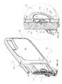
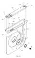
- FIG. 1is a perspective view of a hospital bed showing frame, deck, side rail and combined side rail/over-bed table components as well as a region for a mattress.
- FIG. 2is a perspective view of the siderail/over-bed table of FIG. 1 as seen from the occupant's side of the siderail/over-bed table unit.
- FIG. 3Ais a view of the siderail/over-bed unit of FIG. 2 cutaway to reveal internal components of the unit, including a button shown in a neutral state.
- FIG. 3Bis an enlarged view of a portion of FIG. 3A .
- FIG. 4is an exploded view of components visible in FIGS. 3A and 3B .
- FIG. 5is an assembled view of the components of FIG. 4 .
- FIG. 6is a view similar to FIG. 3B showing the button in a depressed state.
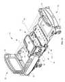
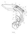
- FIG. 7is a view similar to that of FIG. 2 showing the combined siderail/over-bed table unit having been rotated 90° about a heel axis.
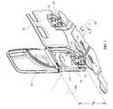
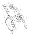
- FIG. 8is a view similar to that of FIG. 7 showing an extension portion of the siderail/over-bed table unit having been rotated about a drop axis relative to a heel portion of the unit.
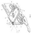
- FIG. 9is a view similar to FIG. 8 showing the extension having been rotated to a substantially horizontal orientation, and with certain portions of the extension broken away to reveal additional features of the siderail/over-bed table unit.
- FIG. 10is a view similar to FIG. 1 showing the siderail/over-bed table unit in the orientation of FIG. 9 .
- FIG. 11is an exploded view showing components of the siderail/over-bed table unit.
- FIG. 12is a view of the heel component of FIG. 11 with selected components having been assembled.
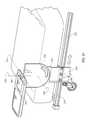
- FIG. 13is a view similar to FIG. 8 as seen by an observer positioned more toward the head end of the bed.
- FIG. 14is a view similar to FIG. 13 with the extension portion of the siderail/over-bed table unit shown in phantom and rotated toward a more horizontal orientation.
- FIG. 15is a view similar to FIG. 13 showing the siderail/over-bed table unit rotated toward a more horizontal position.
- FIG. 16is a view similar to FIG. 9 showing the extension portion of the siderail/over-bed table unit rotated slightly about a swing axis.
- FIG. 17is a view similar to FIG. 16 showing the extension portion as seen from underneath and further rotated about the swing axis.
- FIG. 18is a view similar to FIG. 16 showing the extension portion further rotated about the swing axis.
- FIG. 19is a perspective view of a portion of a hospital bed showing a second embodiment of a siderail/over-bed table in both a raised (solid lines) and a lowered (phantom) position.
- FIG. 20is a view similar to FIG. 19 showing the combined siderail/over-bed table unit rotated 90° about the heel axis.
- FIG. 21is a view similar to FIG. 20 showing an extension portion of the unit rotated 90° about a drop axis and also showing an occupant interface device unfolded from a surface of the extension.
- FIG. 22is a view similar to FIG. 21 with the siderail/over-bed table unit translated more toward the foot end of the bed.
- FIG. 23is a view similar to FIG. 22 showing the extension portion of the unit rotated approximately 90° about a swing axis toward the head end of the bed.
- FIG. 24is a view similar to FIG. 22 showing at the extension portion of the unit rotated approximately 90° about a swing axis toward the foot end of the bed.
- FIG. 1shows a hospital bed 20 having a left side 22 a right side 24 laterally spaced from the right side, a head end 26 and a foot end 28 longitudinally spaced from the head end.
- the bedincludes a frame 30 , a headboard 36 and a footboard 38 attached to the frame, and left and right head end siderails 40 , only the right one of which is shown.
- the bedalso includes at least one siderail/over-bed table (OBT) unit 42 , shown on the right side of the bed near the foot end.
- the left side foot end of the bedmay have a similar unit or may have a conventional foot end siderail.
- the framealso includes one or more deck sections 46 , at least one of which is orientation adjustable.
- the framedefines, at least in part, a spatial region 48 , shown in phantom, for a mattress.
- the mattress regionhas dimensions corresponding to a mattress, not shown, intended to be placed on the frame.
- the framealso includes four mechanisms 50 each having a mounting plate 52 concealed under a plastic cover 56 Each mounting plate is associated with either one of the conventional siderails or with the combined siderail/OBT unit 42 .
- the illustrated mechanismsare four bar linkage “drop down” mechanisms.
- Each mechanism associated with a siderailis connected to the siderail to support the siderail and allow it to be moved vertically between a raised or deployed position, as shown, and a lowered or retracted position.
- the mechanismincludes a latch (not depicted) to secure the siderail or combined siderail/OBT in the raised position.
- a release handle 44is provided to allow a user to release the latch.
- the mounting plate 52 of the mechanism associated with the siderail/OBT unitis connected to a base plate 54 , which is stationary relative to the mounting plate.
- the base plateconnects the combined siderail/OBT unit 42 to the mechanism 50 , to support the unit and allow it to be moved vertically between raised and lowered positions.
- the mechanismincludes a latch (not depicted) to secure the combined siderail/OBT in the raised position.
- a release handle 44is provided to allow a user to release the latch.
- the connection between the siderail/OBT unit and the frameis a permanent connection in that the siderail/OBT, despite being attached to the frame, is not normally intended to be easily detached from the frame.
- the siderail/OBThas a siderail position in which the unit borders the mattress region 48 thereby serving as a siderail.
- the unitwhen in its siderail position, is immediately proximate to the lateral extremity of the mattress region 48 so that the unit is sufficiently close to the mattress to serve as a siderail. That is, the unit is laterally outboard of the mattress, but close enough to the mattress to not leave an objectionably large lateral gap between the unit and the mattress.
- the thickness t of the unitis small in comparison to its other two dimensions, D 1 and D 2 , therefore the unit extends predominantly in the longitudinal and vertical directions when in the siderail position.
- the combined siderail/OBTincludes a heel 58 pivotably connected to base plate 54 so that the heel is rotatable about laterally extending heel axis 60 .
- the base platehas two substantially parallel surfaces 59 , 61 and a curved surface 63 extending between the parallel surfaces. Surface 61 is more readily visible in FIG. 13 .
- the base plateresides in a recess 64 of the heel.
- the recesshas two substantially perpendicular surfaces 65 , 67 and a curved surface 69 extending between the perpendicular surfaces. Surfaces 67 and 69 are more readily visible in FIG. 12 ; surface 65 is more readily visible in FIG. 15 .
- the siderail/OBTalso includes an extension 62 extending from the heel.
- first dimension d 1extends longitudinally and second dimension d 2 extends vertically.
- FIGS. 3-6show further details of the pivotable connection between heel 58 and base plate 54 .
- a latch plate 66having a central cruciform opening 68 with a set of four equiangularly distributed notches 70 is secured to the base plate 54 .
- the heelincludes an opening 72 with a shoulder 74 .
- a laterally translatable button 76occupies the opening.
- the buttonhas a face 78 , a rim 80 , a flange 82 , a hub 84 extending from the back of the face and four equiangularly distributed lugs 86 projecting radially from the distal end of the hub.
- An integral key 90having an inclined profile extends from the rim to the flange.
- FIGS. 3A and 3Bdepict the button in a neutral state in which each lug 86 engages a notch 70 in the latch plate 66 . As a result of this engagement, rotational movement of heel 58 relative to frame 30 , which includes latch plate 66 and base plate 54 , is prohibited.
- FIG. 7shows the unit after having been pivoted 90 degrees from the orientation of FIG. 1 . If desired, heel dimension d H can be made long enough to impede access to release handle 44 ( FIG. 1 ) when the heel is pivoted to the orientation of FIG. 7 .
- recess surface 65engages base plate surface 59 to prevent over-rotation of the heel in direction R 1 even if release button 76 is pressed.
- recess surface 67engages base plate surface 61 to prevent over-rotation of the heel in direction R 2 even if release button 76 is pressed.
- the extension and the heelhave mutually proximate ends 96 , 98 that face each other when the extension and heel are in the substantially coplanar orientation of FIGS. 1 and 7 .
- the extensionis pivotable relative to the heel about a drop axis 100 parallel to the mutually proximate ends.
- a userwould not normally pivot the extension about the drop axis without having first effected the 90 degree orientation change of FIG. 7 (relative to FIG. 1 ).
- the extensioncan be pivoted inboard (i.e. toward the occupant side of the siderail/OBT) about the drop axis ( FIG. 8 ) and placed in a table position, seen in FIGS.
- the extensionin which the extension, or at least a substantial portion thereof, overlies mattress region 48 with the extension, or at least a table surface 102 thereof, in a horizontal orientation thereby serving as an over-bed table for the occupant.
- the extensionWhen the unit is in the table position, the extension extends predominantly in the longitudinal and lateral directions so that the first dimension d 1 extends laterally and the second dimension d 2 extends longitudinally.
- FIGS. 11-15shows further details of the heel and extension.
- End 96 of the heelis flared to define an inboard wall 104 and an outboard wall 106 with a semi-cylindrical trough 108 between the walls.
- Bridges 110span between the walls.
- a semi-cylindrical roller 112resides in the trough and is retained therein by a pair of hinge pins 114 each of which projects from the roller and extends into an opening 116 in the adjacent bridge 110 .
- the pinsdefine the drop axis 100 .
- a stud 118projects from the roller near one of the bridges.
- the studdefines a swing axis 122 , which is perpendicular to drop axis 100 .
- an L-shaped groove 126extends through inboard wall 104 and is partially bordered by an overhang 128 .
- a rectangular groove 130extends through the outboard wall.
- An L-shaped groove 132extends through the roller.
- the L-shaped and rectangular grooves 126 , 130 , 132cooperate with each other to define a guide slot 138 in the heel.
- a curved rail 134also partially visible in FIG. 13 , projects from the underside of the extension.
- the railhas a nominal radius of curvature R ( FIG. 13 ) centered on the swing axis 122 .
- One end 135 of the railhas a rectangular profile.
- Most of the railhas an L-shaped profile with a foot portion 136 ( FIG. 9 ).
- the extensionWhen the heel and the extension are in the coplanar relative orientation of FIG. 7 , the extension is rotatable about the drop axis 100 , but not about swing axis 122 because end 96 of the heel contacts end 98 of the extension to block rotation of the extension about the swing axis. As the extension is lowered toward a 90 degree relative orientation ( FIG. 8 ), any significant rotation about the swing axis is similarly impeded.
- the extensionWhen the extension is at the 90 degree orientation ( FIGS. 9 and 10 ) its underside is substantially parallel to end 96 of the heel and rests on the inboard wall 104 of the heel. In addition the rail 134 registers with the guide slot 138 . Accordingly, as seen in FIG.
- a usercan pivot the extension about swing axis 122 to swing the extension laterally outwardly to a secondary position ( FIG. 18 ) at which the first dimension d 1 extends predominantly longitudinally and the second dimension d 2 extends predominantly laterally. Swinging the extension about the swing axis causes rail 134 to engage guide slot 138 . After the rail enters the guide slot, rail foot 136 cooperates with wall overhang 128 to prevent upward rotation of the extension about drop axis 100 .
- the guide slot 138may have a nominal radius of curvature substantially equal to the radius of curvature R of the rail 134 or may be a linearly extending slot dimensioned to accommodate rotation of the rail about the swing axis.
- FIGS. 19-24show an alternative embodiment 242 of the combination siderail/OBT unit.
- the bed frame 230includes a longitudinally extending track 252 .
- a support plate 254is translatably joined to the track, for example by rollers 256 .
- a sleeve 257is connected to the support plate and is vertically translatable relative to the support plate.
- the siderail/OBT unithas a heel portion 258 pivotably connected to the sleeve so that the heel is pivotable about heel axis 260 .
- An extension 262extends from the heel and is pivotably connected thereto so that the extension is pivotable relative to the heel about drop axis 216 .
- the slidable connection between sleeve 257 and support plate 254allows the unit to be adjusted between a raised position (solid lines) and a lowered position (phantom) below the top surface of the mattress.
- FIG. 20shows the unit after a user has pivoted the heel, and therefore the extension as well, ninety degrees about heel axis 260 .
- FIG. 21shows the unit in the table position achieved by subsequently pivoting the extension 90 degrees about the drop axis 216 .
- the siderail/OBT unitalso includes an occupant interface device 264 that folds down flush with table surface 202 as seen in FIGS. 19-20 and unfolds away from surface 202 as seen in FIG. 21 .
- Device 264is pivotable about a device axis 266 . Examples of the specific types of devices include a keypad allowing the occupant to command certain functions of the bed, and an information display.
- FIG. 22shows the unit having been longitudinally translated relative to its position in FIG. 21 .
- the translatabilityis a consequence of the translatable connection between support plate 254 and track 252 .
- the extensionis also pivotable relative to the heel about a swing axis 222 .
- the various embodiments of the unitare useful as an over-bed table, they retain, when in the siderail position, all the typical functionality of a siderail. For example they can be raised to a deployed position to define the lateral edges of the mattress and can be retracted to a stowed position to allow for occupant ingress and egress and to allow an attendant to access the occupant.
- the extensionplays two mutually exclusive roles. It serves as part of the siderail when the unit is in the siderail position, but serves as a table when the unit is in the table or secondary position.
- part of the unit(heel 58 of the first embodiment and support plate 254 and sleeve 257 of the second embodiment) are at least partially effective as a siderail insofar as those parts define the lateral edge of the mattress.
Landscapes
- Health & Medical Sciences (AREA)
- Nursing (AREA)
- Life Sciences & Earth Sciences (AREA)
- Animal Behavior & Ethology (AREA)
- General Health & Medical Sciences (AREA)
- Public Health (AREA)
- Veterinary Medicine (AREA)
- Invalid Beds And Related Equipment (AREA)
Abstract
Description
Claims (21)
Priority Applications (2)
| Application Number | Priority Date | Filing Date | Title |
|---|---|---|---|
| US12/701,042US9492340B2 (en) | 2010-02-05 | 2010-02-05 | Combined siderail and over-bed table |
| EP11152518AEP2353566A3 (en) | 2010-02-05 | 2011-01-28 | Combined siderail and over-bed table |
Applications Claiming Priority (1)
| Application Number | Priority Date | Filing Date | Title |
|---|---|---|---|
| US12/701,042US9492340B2 (en) | 2010-02-05 | 2010-02-05 | Combined siderail and over-bed table |
Publications (2)
| Publication Number | Publication Date |
|---|---|
| US20110191957A1 US20110191957A1 (en) | 2011-08-11 |
| US9492340B2true US9492340B2 (en) | 2016-11-15 |
Family
ID=43927755
Family Applications (1)
| Application Number | Title | Priority Date | Filing Date |
|---|---|---|---|
| US12/701,042Active2033-06-04US9492340B2 (en) | 2010-02-05 | 2010-02-05 | Combined siderail and over-bed table |
Country Status (2)
| Country | Link |
|---|---|
| US (1) | US9492340B2 (en) |
| EP (1) | EP2353566A3 (en) |
Cited By (3)
| Publication number | Priority date | Publication date | Assignee | Title |
|---|---|---|---|---|
| US10489661B1 (en) | 2016-03-08 | 2019-11-26 | Ocuvera LLC | Medical environment monitoring system |
| US10600204B1 (en) | 2016-12-28 | 2020-03-24 | Ocuvera | Medical environment bedsore detection and prevention system |
| US11389354B2 (en) | 2017-11-30 | 2022-07-19 | Stryker Corporation | Multi-function headboard for patient support apparatus |
Families Citing this family (23)
| Publication number | Priority date | Publication date | Assignee | Title |
|---|---|---|---|---|
| US8621688B2 (en)* | 2010-12-13 | 2014-01-07 | Hill-Rom Services, Inc. | Siderail assembly for patient support apparatus |
| USD656765S1 (en)* | 2011-05-02 | 2012-04-03 | Linet Spol. S.R.O. | Footboard |
| USD668087S1 (en)* | 2011-05-02 | 2012-10-02 | Linet Spol. S R.O. | Siderail |
| USD656762S1 (en)* | 2011-05-02 | 2012-04-03 | Linet Spol. S.R.O. | Siderail |
| USD656764S1 (en)* | 2011-05-02 | 2012-04-03 | Linet Spol. S R.O. | Headboard |
| US20130086746A1 (en)* | 2011-10-10 | 2013-04-11 | Irvin J. Vanderpohl | Patient support apparatus with movable siderail assembly |
| CN102525757A (en)* | 2011-12-29 | 2012-07-04 | 佛山科学技术学院 | Hospital bed with multifunctional support frame |
| JP5922608B2 (en)* | 2013-03-22 | 2016-05-24 | ジーイー・メディカル・システムズ・グローバル・テクノロジー・カンパニー・エルエルシー | Medical device table and medical device |
| USD710510S1 (en) | 2013-09-23 | 2014-08-05 | Hill-Rom Services Pte. Ltd. | Foot rail for a patient bed |
| USD710507S1 (en) | 2013-09-23 | 2014-08-05 | Hill-Rom Services Pte. Ltd. | Patient bed |
| USD710509S1 (en) | 2013-09-23 | 2014-08-05 | Hill-Rom Services Pte. Ltd. | Head rail for a patient bed |
| US9463126B2 (en)* | 2014-03-11 | 2016-10-11 | Hill-Rom Services, Inc. | Caregiver universal remote cart for patient bed control |
| USD768422S1 (en) | 2014-08-12 | 2016-10-11 | Hill-Rom Services, Inc. | Foot end siderail |
| USD769042S1 (en) | 2014-08-12 | 2016-10-18 | Hill-Rom Services, Inc. | Head end siderail |
| USD770824S1 (en) | 2014-08-12 | 2016-11-08 | Hill-Rom Services, Inc. | Barrier for a hospital bed |
| USD771259S1 (en) | 2015-01-29 | 2016-11-08 | Hill-Rom Services, Inc. | Foot rail for patient bed |
| USD770829S1 (en) | 2015-01-29 | 2016-11-08 | Hill-Rom Services, Inc. | Head rail for patient bed |
| GB2542875B (en)* | 2016-04-18 | 2017-10-25 | Accora Ltd | Bed frame |
| USD804883S1 (en) | 2016-05-28 | 2017-12-12 | Hill-Rom Services, Inc. | Footrail |
| USD804882S1 (en) | 2016-05-28 | 2017-12-12 | Hill-Rom Services, Inc. | Headrail |
| USD848621S1 (en)* | 2017-05-22 | 2019-05-14 | Gbuk Limited | Bed adapter |
| USD962676S1 (en)* | 2019-05-28 | 2022-09-06 | Christopher Eng | Bedside shelf |
| CN112545784B (en)* | 2020-12-29 | 2021-09-17 | 青岛大学附属医院 | Nursing bed and operation method |
Citations (23)
| Publication number | Priority date | Publication date | Assignee | Title |
|---|---|---|---|---|
| GB191019806A (en) | 1909-08-27 | 1910-12-15 | Martin Mclane | Improvements in or relating to Wrenches for Screwing Flanges or Sockets on Pipes. |
| US3543312A (en) | 1967-08-12 | 1970-12-01 | Ital Bed Cost Letti Affini | Table unit mountable on a bed frame |
| US5035464A (en)* | 1989-10-03 | 1991-07-30 | Howard Spallholtz | Snack tray assembly |
| US5038434A (en) | 1991-02-19 | 1991-08-13 | Navarrette Philip F | Bed supported tray apparatus |
| US5279010A (en) | 1988-03-23 | 1994-01-18 | American Life Support Technology, Inc. | Patient care system |
| US5315726A (en) | 1992-09-15 | 1994-05-31 | Martin Borenstein | Multipurpose convertible furniture assembly |
| US5359741A (en) | 1993-04-21 | 1994-11-01 | Brian Lang | Rotatable and removable bed tray |
| US5575535A (en) | 1995-08-22 | 1996-11-19 | Burchett; Mark R. | Couch with retractable guard member |
| US5606917A (en) | 1993-11-17 | 1997-03-04 | Cauffiel; Ford B. | Table assembly with slidable table |
| US6195820B1 (en)* | 1999-05-27 | 2001-03-06 | Hill-Rom, Inc. | Pivoting hand table |
| US6862759B2 (en) | 1998-06-26 | 2005-03-08 | Hill-Rom Services, Inc. | Hospital bed |
| US6957461B2 (en) | 1999-12-29 | 2005-10-25 | Hill-Rom Services, Inc. | Hospital bed |
| US20060056616A1 (en) | 2004-09-10 | 2006-03-16 | Heimbrock Richard H | Hospital telephone and device controller |
| US7017208B2 (en) | 1995-08-04 | 2006-03-28 | Hill-Rom Services, Inc. | Hospital bed |
| US7082882B2 (en) | 2003-08-12 | 2006-08-01 | Hill-Rom Services, Inc. | Frame mounted overbed table |
| US7234182B2 (en)* | 1998-09-09 | 2007-06-26 | Standers, Inc. | Assist device for getting into and out of sitting or reclined positions |
| US7243386B2 (en) | 2001-05-25 | 2007-07-17 | Hill-Rom Services, Inc. | Docking station for patient support |
| US20070174965A1 (en) | 2005-12-19 | 2007-08-02 | Stryker Corporation | Hospital bed |
| US20080235872A1 (en) | 2007-03-30 | 2008-10-02 | Newkirk David C | User interface for hospital bed |
| US7472439B2 (en) | 2005-02-23 | 2009-01-06 | Stryker Canadian Management, Inc. | Hospital patient support |
| US20090064415A1 (en) | 2007-09-07 | 2009-03-12 | Michael Payne | Portable Self-Contained Bed-On-Demand System |
| GB2458164A (en) | 2008-03-08 | 2009-09-09 | Brian Hurditch | Support apparatus |
| US7600277B2 (en)* | 2004-06-03 | 2009-10-13 | Hill-Rom Services, Inc. | Foldout bed headwall structure |
Family Cites Families (1)
| Publication number | Priority date | Publication date | Assignee | Title |
|---|---|---|---|---|
| GB190919806A (en)* | 1909-08-30 | 1910-06-09 | John Greenhough Bunting | Improvements in or relating to Couches, Bedsteads, and the like. |
- 2010
- 2010-02-05USUS12/701,042patent/US9492340B2/enactiveActive
- 2011
- 2011-01-28EPEP11152518Apatent/EP2353566A3/ennot_activeWithdrawn
Patent Citations (23)
| Publication number | Priority date | Publication date | Assignee | Title |
|---|---|---|---|---|
| GB191019806A (en) | 1909-08-27 | 1910-12-15 | Martin Mclane | Improvements in or relating to Wrenches for Screwing Flanges or Sockets on Pipes. |
| US3543312A (en) | 1967-08-12 | 1970-12-01 | Ital Bed Cost Letti Affini | Table unit mountable on a bed frame |
| US5279010A (en) | 1988-03-23 | 1994-01-18 | American Life Support Technology, Inc. | Patient care system |
| US5035464A (en)* | 1989-10-03 | 1991-07-30 | Howard Spallholtz | Snack tray assembly |
| US5038434A (en) | 1991-02-19 | 1991-08-13 | Navarrette Philip F | Bed supported tray apparatus |
| US5315726A (en) | 1992-09-15 | 1994-05-31 | Martin Borenstein | Multipurpose convertible furniture assembly |
| US5359741A (en) | 1993-04-21 | 1994-11-01 | Brian Lang | Rotatable and removable bed tray |
| US5606917A (en) | 1993-11-17 | 1997-03-04 | Cauffiel; Ford B. | Table assembly with slidable table |
| US7017208B2 (en) | 1995-08-04 | 2006-03-28 | Hill-Rom Services, Inc. | Hospital bed |
| US5575535A (en) | 1995-08-22 | 1996-11-19 | Burchett; Mark R. | Couch with retractable guard member |
| US6862759B2 (en) | 1998-06-26 | 2005-03-08 | Hill-Rom Services, Inc. | Hospital bed |
| US7234182B2 (en)* | 1998-09-09 | 2007-06-26 | Standers, Inc. | Assist device for getting into and out of sitting or reclined positions |
| US6195820B1 (en)* | 1999-05-27 | 2001-03-06 | Hill-Rom, Inc. | Pivoting hand table |
| US6957461B2 (en) | 1999-12-29 | 2005-10-25 | Hill-Rom Services, Inc. | Hospital bed |
| US7243386B2 (en) | 2001-05-25 | 2007-07-17 | Hill-Rom Services, Inc. | Docking station for patient support |
| US7082882B2 (en) | 2003-08-12 | 2006-08-01 | Hill-Rom Services, Inc. | Frame mounted overbed table |
| US7600277B2 (en)* | 2004-06-03 | 2009-10-13 | Hill-Rom Services, Inc. | Foldout bed headwall structure |
| US20060056616A1 (en) | 2004-09-10 | 2006-03-16 | Heimbrock Richard H | Hospital telephone and device controller |
| US7472439B2 (en) | 2005-02-23 | 2009-01-06 | Stryker Canadian Management, Inc. | Hospital patient support |
| US20070174965A1 (en) | 2005-12-19 | 2007-08-02 | Stryker Corporation | Hospital bed |
| US20080235872A1 (en) | 2007-03-30 | 2008-10-02 | Newkirk David C | User interface for hospital bed |
| US20090064415A1 (en) | 2007-09-07 | 2009-03-12 | Michael Payne | Portable Self-Contained Bed-On-Demand System |
| GB2458164A (en) | 2008-03-08 | 2009-09-09 | Brian Hurditch | Support apparatus |
Non-Patent Citations (2)
| Title |
|---|
| Communication pursuant to Article 94(3) EPC for EP Application No. 11152518.4, mailed Aug. 14, 2014; received Aug. 19, 2014. |
| Extended EP Search Report; Date of Completion of the Search-Jan. 31, 2013; Place of Search-The Hague; Date Mailed-Feb. 11, 2013. |
Cited By (4)
| Publication number | Priority date | Publication date | Assignee | Title |
|---|---|---|---|---|
| US10489661B1 (en) | 2016-03-08 | 2019-11-26 | Ocuvera LLC | Medical environment monitoring system |
| US10600204B1 (en) | 2016-12-28 | 2020-03-24 | Ocuvera | Medical environment bedsore detection and prevention system |
| US11389354B2 (en) | 2017-11-30 | 2022-07-19 | Stryker Corporation | Multi-function headboard for patient support apparatus |
| US11723823B2 (en) | 2017-11-30 | 2023-08-15 | Stryker Corporation | Multi-function headboard for patient support apparatus |
Also Published As
| Publication number | Publication date |
|---|---|
| EP2353566A3 (en) | 2013-03-13 |
| EP2353566A2 (en) | 2011-08-10 |
| US20110191957A1 (en) | 2011-08-11 |
Similar Documents
| Publication | Publication Date | Title |
|---|---|---|
| US9492340B2 (en) | Combined siderail and over-bed table | |
| US20080178778A1 (en) | Latch assembly with remote release | |
| US5394580A (en) | Hospital bed with three position patient side guards | |
| JP5087286B2 (en) | Patient support device with automatic shape adjustment function | |
| US8104117B2 (en) | Siderail and control unit therefor | |
| US5485699A (en) | Hospital bed guard | |
| US20050034637A1 (en) | Frame mounted overbed table | |
| US20120246830A1 (en) | Footboard egress design | |
| US20090000033A1 (en) | Patient table with footrest extension | |
| KR20170028814A (en) | Adjustable height desk platform | |
| US8733829B2 (en) | Composite chair | |
| US7810189B2 (en) | Folding bed | |
| CN110893139B (en) | Nursing Bed | |
| US20100107932A1 (en) | Table device | |
| US5802988A (en) | Vertically adjustable table | |
| US3207099A (en) | Overbed table | |
| JP2010000213A (en) | Table mounting structure serving also as footboard of bed | |
| TWI613983B (en) | Adjustable height desk platform and method of using the same | |
| CN213157140U (en) | Novel sickbed | |
| EP2100579B1 (en) | Siderail and control unit therefor | |
| JP2005334433A (en) | Bed equipment | |
| JP4001506B2 (en) | Bed table equipment | |
| US4240170A (en) | Adjustable foot brace | |
| JP3957991B2 (en) | Rotating bed structure in a retractable infant bed | |
| JP2004121441A (en) | Locking device of folding table |
Legal Events
| Date | Code | Title | Description |
|---|---|---|---|
| AS | Assignment | Owner name:HILL-ROM SERVICES, INC., DELAWARE Free format text:ASSIGNMENT OF ASSIGNORS INTEREST;ASSIGNORS:HORNBACH, DAVID W;HEIMBROCK, RICHARD H;TURNER, JONATHAN D;AND OTHERS;SIGNING DATES FROM 20100204 TO 20100205;REEL/FRAME:023906/0350 | |
| AS | Assignment | Owner name:JPMORGAN CHASE BANK, N.A., AS COLLATERAL AGENT, ILLINOIS Free format text:SECURITY INTEREST;ASSIGNORS:ALLEN MEDICAL SYSTEMS, INC.;HILL-ROM SERVICES, INC.;ASPEN SURGICAL PRODUCTS, INC.;AND OTHERS;REEL/FRAME:036582/0123 Effective date:20150908 Owner name:JPMORGAN CHASE BANK, N.A., AS COLLATERAL AGENT, IL Free format text:SECURITY INTEREST;ASSIGNORS:ALLEN MEDICAL SYSTEMS, INC.;HILL-ROM SERVICES, INC.;ASPEN SURGICAL PRODUCTS, INC.;AND OTHERS;REEL/FRAME:036582/0123 Effective date:20150908 | |
| AS | Assignment | Owner name:HILL-ROM SERVICES, INC. (INDIANA CORPORATION), IND Free format text:CHANGE OF STATE OF INCORPORATION FROM DELAWARE TO INDIANA;ASSIGNOR:HILL-ROM SERVICES, INC. (DELAWARE CORPORATION);REEL/FRAME:039973/0434 Effective date:20101231 | |
| AS | Assignment | Owner name:JPMORGAN CHASE BANK, N.A., AS COLLATERAL AGENT, ILLINOIS Free format text:SECURITY AGREEMENT;ASSIGNORS:HILL-ROM SERVICES, INC.;ASPEN SURGICAL PRODUCTS, INC.;ALLEN MEDICAL SYSTEMS, INC.;AND OTHERS;REEL/FRAME:040145/0445 Effective date:20160921 Owner name:JPMORGAN CHASE BANK, N.A., AS COLLATERAL AGENT, IL Free format text:SECURITY AGREEMENT;ASSIGNORS:HILL-ROM SERVICES, INC.;ASPEN SURGICAL PRODUCTS, INC.;ALLEN MEDICAL SYSTEMS, INC.;AND OTHERS;REEL/FRAME:040145/0445 Effective date:20160921 | |
| STCF | Information on status: patent grant | Free format text:PATENTED CASE | |
| AS | Assignment | Owner name:ALLEN MEDICAL SYSTEMS, INC., ILLINOIS Free format text:RELEASE BY SECURED PARTY;ASSIGNOR:JPMORGAN CHASE BANK, N.A.;REEL/FRAME:050254/0513 Effective date:20190830 Owner name:VOALTE, INC., FLORIDA Free format text:RELEASE BY SECURED PARTY;ASSIGNOR:JPMORGAN CHASE BANK, N.A.;REEL/FRAME:050254/0513 Effective date:20190830 Owner name:HILL-ROM, INC., ILLINOIS Free format text:RELEASE BY SECURED PARTY;ASSIGNOR:JPMORGAN CHASE BANK, N.A.;REEL/FRAME:050254/0513 Effective date:20190830 Owner name:WELCH ALLYN, INC., NEW YORK Free format text:RELEASE BY SECURED PARTY;ASSIGNOR:JPMORGAN CHASE BANK, N.A.;REEL/FRAME:050254/0513 Effective date:20190830 Owner name:MORTARA INSTRUMENT SERVICES, INC., WISCONSIN Free format text:RELEASE BY SECURED PARTY;ASSIGNOR:JPMORGAN CHASE BANK, N.A.;REEL/FRAME:050254/0513 Effective date:20190830 Owner name:MORTARA INSTRUMENT, INC., WISCONSIN Free format text:RELEASE BY SECURED PARTY;ASSIGNOR:JPMORGAN CHASE BANK, N.A.;REEL/FRAME:050254/0513 Effective date:20190830 Owner name:ANODYNE MEDICAL DEVICE, INC., FLORIDA Free format text:RELEASE BY SECURED PARTY;ASSIGNOR:JPMORGAN CHASE BANK, N.A.;REEL/FRAME:050254/0513 Effective date:20190830 Owner name:HILL-ROM COMPANY, INC., ILLINOIS Free format text:RELEASE BY SECURED PARTY;ASSIGNOR:JPMORGAN CHASE BANK, N.A.;REEL/FRAME:050254/0513 Effective date:20190830 Owner name:HILL-ROM SERVICES, INC., ILLINOIS Free format text:RELEASE BY SECURED PARTY;ASSIGNOR:JPMORGAN CHASE BANK, N.A.;REEL/FRAME:050254/0513 Effective date:20190830 | |
| AS | Assignment | Owner name:JPMORGAN CHASE BANK, N.A., ILLINOIS Free format text:SECURITY AGREEMENT;ASSIGNORS:HILL-ROM HOLDINGS, INC.;HILL-ROM, INC.;HILL-ROM SERVICES, INC.;AND OTHERS;REEL/FRAME:050260/0644 Effective date:20190830 | |
| MAFP | Maintenance fee payment | Free format text:PAYMENT OF MAINTENANCE FEE, 4TH YEAR, LARGE ENTITY (ORIGINAL EVENT CODE: M1551); ENTITY STATUS OF PATENT OWNER: LARGE ENTITY Year of fee payment:4 | |
| AS | Assignment | Owner name:HILL-ROM HOLDINGS, INC., ILLINOIS Free format text:RELEASE OF SECURITY INTEREST AT REEL/FRAME 050260/0644;ASSIGNOR:JPMORGAN CHASE BANK, N.A.;REEL/FRAME:058517/0001 Effective date:20211213 Owner name:BARDY DIAGNOSTICS, INC., ILLINOIS Free format text:RELEASE OF SECURITY INTEREST AT REEL/FRAME 050260/0644;ASSIGNOR:JPMORGAN CHASE BANK, N.A.;REEL/FRAME:058517/0001 Effective date:20211213 Owner name:VOALTE, INC., FLORIDA Free format text:RELEASE OF SECURITY INTEREST AT REEL/FRAME 050260/0644;ASSIGNOR:JPMORGAN CHASE BANK, N.A.;REEL/FRAME:058517/0001 Effective date:20211213 Owner name:HILL-ROM, INC., ILLINOIS Free format text:RELEASE OF SECURITY INTEREST AT REEL/FRAME 050260/0644;ASSIGNOR:JPMORGAN CHASE BANK, N.A.;REEL/FRAME:058517/0001 Effective date:20211213 Owner name:WELCH ALLYN, INC., NEW YORK Free format text:RELEASE OF SECURITY INTEREST AT REEL/FRAME 050260/0644;ASSIGNOR:JPMORGAN CHASE BANK, N.A.;REEL/FRAME:058517/0001 Effective date:20211213 Owner name:ALLEN MEDICAL SYSTEMS, INC., ILLINOIS Free format text:RELEASE OF SECURITY INTEREST AT REEL/FRAME 050260/0644;ASSIGNOR:JPMORGAN CHASE BANK, N.A.;REEL/FRAME:058517/0001 Effective date:20211213 Owner name:HILL-ROM SERVICES, INC., ILLINOIS Free format text:RELEASE OF SECURITY INTEREST AT REEL/FRAME 050260/0644;ASSIGNOR:JPMORGAN CHASE BANK, N.A.;REEL/FRAME:058517/0001 Effective date:20211213 Owner name:BREATHE TECHNOLOGIES, INC., CALIFORNIA Free format text:RELEASE OF SECURITY INTEREST AT REEL/FRAME 050260/0644;ASSIGNOR:JPMORGAN CHASE BANK, N.A.;REEL/FRAME:058517/0001 Effective date:20211213 | |
| MAFP | Maintenance fee payment | Free format text:PAYMENT OF MAINTENANCE FEE, 8TH YEAR, LARGE ENTITY (ORIGINAL EVENT CODE: M1552); ENTITY STATUS OF PATENT OWNER: LARGE ENTITY Year of fee payment:8 |