US9492277B2 - Soft body tissue remodeling methods and apparatus - Google Patents
Soft body tissue remodeling methods and apparatusDownload PDFInfo
- Publication number
- US9492277B2 US9492277B2US11/215,341US21534105AUS9492277B2US 9492277 B2US9492277 B2US 9492277B2US 21534105 AUS21534105 AUS 21534105AUS 9492277 B2US9492277 B2US 9492277B2
- Authority
- US
- United States
- Prior art keywords
- screw
- prosthesis
- tissue
- collar
- structures
- Prior art date
- Legal status (The legal status is an assumption and is not a legal conclusion. Google has not performed a legal analysis and makes no representation as to the accuracy of the status listed.)
- Active, expires
Links
- 238000000034methodMethods0.000titledescription23
- 230000007838tissue remodelingEffects0.000titledescription4
- 125000006850spacer groupChemical group0.000claimsabstractdescription50
- 210000001519tissueAnatomy0.000claimsdescription75
- 210000004872soft tissueAnatomy0.000claimsdescription5
- 239000004020conductorSubstances0.000claimsdescription3
- 238000003780insertionMethods0.000claimsdescription3
- 230000037431insertionEffects0.000claimsdescription3
- 230000003247decreasing effectEffects0.000claimsdescription2
- 230000008878couplingEffects0.000claims1
- 238000010168coupling processMethods0.000claims1
- 238000005859coupling reactionMethods0.000claims1
- 210000003748coronary sinusAnatomy0.000abstractdescription28
- 210000004115mitral valveAnatomy0.000abstractdescription19
- 238000004904shorteningMethods0.000abstractdescription9
- 210000005245right atriumAnatomy0.000description9
- 238000010276constructionMethods0.000description8
- BASFCYQUMIYNBI-UHFFFAOYSA-NplatinumChemical compound[Pt]BASFCYQUMIYNBI-UHFFFAOYSA-N0.000description8
- 239000000463materialSubstances0.000description7
- 238000011144upstream manufacturingMethods0.000description5
- 239000003814drugSubstances0.000description4
- 229940079593drugDrugs0.000description4
- 229910052697platinumInorganic materials0.000description4
- 230000008439repair processEffects0.000description4
- 238000004873anchoringMethods0.000description3
- 238000000576coating methodMethods0.000description3
- 230000000295complement effectEffects0.000description3
- 210000004165myocardiumAnatomy0.000description3
- 230000035515penetrationEffects0.000description3
- 229920000642polymerPolymers0.000description3
- 238000007634remodelingMethods0.000description3
- 239000003356suture materialSubstances0.000description3
- GUVRBAGPIYLISA-UHFFFAOYSA-Ntantalum atomChemical compound[Ta]GUVRBAGPIYLISA-UHFFFAOYSA-N0.000description3
- 238000013459approachMethods0.000description2
- 230000008901benefitEffects0.000description2
- 230000005540biological transmissionEffects0.000description2
- 230000008859changeEffects0.000description2
- 230000006835compressionEffects0.000description2
- 238000007906compressionMethods0.000description2
- 230000002349favourable effectEffects0.000description2
- PCHJSUWPFVWCPO-UHFFFAOYSA-NgoldChemical compound[Au]PCHJSUWPFVWCPO-UHFFFAOYSA-N0.000description2
- 229910052737goldInorganic materials0.000description2
- 239000010931goldSubstances0.000description2
- 210000005003heart tissueAnatomy0.000description2
- 239000007943implantSubstances0.000description2
- 229910052741iridiumInorganic materials0.000description2
- GKOZUEZYRPOHIO-UHFFFAOYSA-Niridium atomChemical compound[Ir]GKOZUEZYRPOHIO-UHFFFAOYSA-N0.000description2
- 229910052751metalInorganic materials0.000description2
- 239000002184metalSubstances0.000description2
- 230000004048modificationEffects0.000description2
- 238000012986modificationMethods0.000description2
- 230000008569processEffects0.000description2
- 230000000717retained effectEffects0.000description2
- 229910001220stainless steelInorganic materials0.000description2
- 239000010935stainless steelSubstances0.000description2
- 229910052715tantalumInorganic materials0.000description2
- 210000001631vena cava inferiorAnatomy0.000description2
- 210000002620vena cava superiorAnatomy0.000description2
- 208000032845Atrial RemodelingDiseases0.000description1
- 206010053567CoagulopathiesDiseases0.000description1
- 229920004934Dacron®Polymers0.000description1
- 229910001226L605Inorganic materials0.000description1
- RTAQQCXQSZGOHL-UHFFFAOYSA-NTitaniumChemical compound[Ti]RTAQQCXQSZGOHL-UHFFFAOYSA-N0.000description1
- 208000033774Ventricular RemodelingDiseases0.000description1
- 230000009286beneficial effectEffects0.000description1
- 230000002457bidirectional effectEffects0.000description1
- 239000000560biocompatible materialSubstances0.000description1
- 230000000747cardiac effectEffects0.000description1
- 230000001684chronic effectEffects0.000description1
- 230000035602clottingEffects0.000description1
- 239000011248coating agentSubstances0.000description1
- 238000002591computed tomographyMethods0.000description1
- 238000002592echocardiographyMethods0.000description1
- 229910000701elgiloys (Co-Cr-Ni Alloy)Inorganic materials0.000description1
- 238000005516engineering processMethods0.000description1
- 238000002594fluoroscopyMethods0.000description1
- 230000035876healingEffects0.000description1
- 230000000004hemodynamic effectEffects0.000description1
- 230000028709inflammatory responseEffects0.000description1
- 238000007914intraventricular administrationMethods0.000description1
- 210000004731jugular veinAnatomy0.000description1
- 210000005246left atriumAnatomy0.000description1
- 210000005240left ventricleAnatomy0.000description1
- 230000007774longtermEffects0.000description1
- 238000002595magnetic resonance imagingMethods0.000description1
- 238000002483medicationMethods0.000description1
- 238000012544monitoring processMethods0.000description1
- HLXZNVUGXRDIFK-UHFFFAOYSA-Nnickel titaniumChemical compound[Ti].[Ti].[Ti].[Ti].[Ti].[Ti].[Ti].[Ti].[Ti].[Ti].[Ti].[Ni].[Ni].[Ni].[Ni].[Ni].[Ni].[Ni].[Ni].[Ni].[Ni].[Ni].[Ni].[Ni].[Ni]HLXZNVUGXRDIFK-UHFFFAOYSA-N0.000description1
- 229910001000nickel titaniumInorganic materials0.000description1
- 229910052758niobiumInorganic materials0.000description1
- 239000010955niobiumSubstances0.000description1
- GUCVJGMIXFAOAE-UHFFFAOYSA-Nniobium atomChemical compound[Nb]GUCVJGMIXFAOAE-UHFFFAOYSA-N0.000description1
- 208000029278non-syndromic brachydactyly of fingersDiseases0.000description1
- 239000005020polyethylene terephthalateSubstances0.000description1
- 230000000069prophylactic effectEffects0.000description1
- 230000004044responseEffects0.000description1
- 229910052719titaniumInorganic materials0.000description1
- 239000010936titaniumSubstances0.000description1
- 230000007704transitionEffects0.000description1
- 210000000591tricuspid valveAnatomy0.000description1
- WFKWXMTUELFFGS-UHFFFAOYSA-NtungstenChemical compound[W]WFKWXMTUELFFGS-UHFFFAOYSA-N0.000description1
- 229910052721tungstenInorganic materials0.000description1
- 239000010937tungstenSubstances0.000description1
- 238000012800visualizationMethods0.000description1
- 230000003313weakening effectEffects0.000description1
Images


Classifications
- A—HUMAN NECESSITIES
- A61—MEDICAL OR VETERINARY SCIENCE; HYGIENE
- A61F—FILTERS IMPLANTABLE INTO BLOOD VESSELS; PROSTHESES; DEVICES PROVIDING PATENCY TO, OR PREVENTING COLLAPSING OF, TUBULAR STRUCTURES OF THE BODY, e.g. STENTS; ORTHOPAEDIC, NURSING OR CONTRACEPTIVE DEVICES; FOMENTATION; TREATMENT OR PROTECTION OF EYES OR EARS; BANDAGES, DRESSINGS OR ABSORBENT PADS; FIRST-AID KITS
- A61F2/00—Filters implantable into blood vessels; Prostheses, i.e. artificial substitutes or replacements for parts of the body; Appliances for connecting them with the body; Devices providing patency to, or preventing collapsing of, tubular structures of the body, e.g. stents
- A61F2/02—Prostheses implantable into the body
- A61F2/24—Heart valves ; Vascular valves, e.g. venous valves; Heart implants, e.g. passive devices for improving the function of the native valve or the heart muscle; Transmyocardial revascularisation [TMR] devices; Valves implantable in the body
- A61F2/2442—Annuloplasty rings or inserts for correcting the valve shape; Implants for improving the function of a native heart valve
- A61F2/2451—Inserts in the coronary sinus for correcting the valve shape
- A—HUMAN NECESSITIES
- A61—MEDICAL OR VETERINARY SCIENCE; HYGIENE
- A61B—DIAGNOSIS; SURGERY; IDENTIFICATION
- A61B17/00—Surgical instruments, devices or methods
- A61B17/12—Surgical instruments, devices or methods for ligaturing or otherwise compressing tubular parts of the body, e.g. blood vessels or umbilical cord
- A61B17/128—Surgical instruments, devices or methods for ligaturing or otherwise compressing tubular parts of the body, e.g. blood vessels or umbilical cord for applying or removing clamps or clips
- A61B17/1285—Surgical instruments, devices or methods for ligaturing or otherwise compressing tubular parts of the body, e.g. blood vessels or umbilical cord for applying or removing clamps or clips for minimally invasive surgery
- A—HUMAN NECESSITIES
- A61—MEDICAL OR VETERINARY SCIENCE; HYGIENE
- A61B—DIAGNOSIS; SURGERY; IDENTIFICATION
- A61B17/00—Surgical instruments, devices or methods
- A61B17/04—Surgical instruments, devices or methods for suturing wounds; Holders or packages for needles or suture materials
- A61B17/0401—Suture anchors, buttons or pledgets, i.e. means for attaching sutures to bone, cartilage or soft tissue; Instruments for applying or removing suture anchors
- A61B2017/0409—Instruments for applying suture anchors
- A—HUMAN NECESSITIES
- A61—MEDICAL OR VETERINARY SCIENCE; HYGIENE
- A61B—DIAGNOSIS; SURGERY; IDENTIFICATION
- A61B17/00—Surgical instruments, devices or methods
- A61B17/04—Surgical instruments, devices or methods for suturing wounds; Holders or packages for needles or suture materials
- A61B17/0401—Suture anchors, buttons or pledgets, i.e. means for attaching sutures to bone, cartilage or soft tissue; Instruments for applying or removing suture anchors
- A61B2017/044—Suture anchors, buttons or pledgets, i.e. means for attaching sutures to bone, cartilage or soft tissue; Instruments for applying or removing suture anchors with a threaded shaft, e.g. screws
- A61B2017/0441—Suture anchors, buttons or pledgets, i.e. means for attaching sutures to bone, cartilage or soft tissue; Instruments for applying or removing suture anchors with a threaded shaft, e.g. screws the shaft being a rigid coil or spiral
- A—HUMAN NECESSITIES
- A61—MEDICAL OR VETERINARY SCIENCE; HYGIENE
- A61B—DIAGNOSIS; SURGERY; IDENTIFICATION
- A61B17/00—Surgical instruments, devices or methods
- A61B17/04—Surgical instruments, devices or methods for suturing wounds; Holders or packages for needles or suture materials
- A61B17/0487—Suture clamps, clips or locks, e.g. for replacing suture knots; Instruments for applying or removing suture clamps, clips or locks
- A61B2017/0488—Instruments for applying suture clamps, clips or locks
Definitions
- This inventionrelates to medical devices and methods. More particularly, the invention relates to prostheses that can be used for such purposes as remodeling soft body tissue structures of a patient, and to instruments and methods that can be used for implanting such prostheses in a patient.
- An example of a context in which this invention can be usedis in a medical procedure that may be referred to as percutaneous mitral valve repair.
- Hindrichs et al.U.S. patent application Ser. No. 10/803,287, filed Mar. 17, 2004 (and hereby incorporated by reference herein in its entirety), shows this type of procedure, and methods and apparatus for performing it.
- An embodiment of this type of procedureincludes percutaneously implanting a first anchor structure in the coronary sinus of the patient (e.g., through the wall of the coronary sinus and into the myocardium below). Then a second anchor structure is percutaneously implanted in the right atrium of the patient outside the ostium of the coronary sinus.
- the distance between the two anchor structuresis reduced by percutaneously tightening a linkage (e.g., of suture material) between those structures.
- a linkagee.g., of suture material
- the percutaneous mitral valve repair procedure mentioned in the preceding paragraphsis only one example of soft body tissue remodeling to which this type of technology may be applied.
- Other examplesinclude (without limitation) (1) remodeling of a patient's left ventricle, (2) intra-atrial remodeling of a patient's mitral valve annulus, (3) intra-ventricular remodeling of a patient's mitral valve annulus, (4) remodeling of features of a patient's tricuspid valve, and (5) other cardiac applications. What is needed in many soft body tissue remodeling applications is long-term (chronic) durability of the prosthesis under dynamic loading of the prosthesis.
- An illustrative anchor structure for use in soft tissue remodelingincludes first and second screw structures that can be driven into tissue a short distance apart along an axis along which the anchor structure will be pulled to remodel the tissue.
- the screw structuresare driven into tissue transverse (e.g., substantially perpendicular) to this axis.
- a tether or linking member or structuree.g., of suture material or of suture-like material extends between head regions of the screw structures (and preferably also beyond the screw structures to the site of another more-distant anchor structure along the above-mentioned axis).
- a spacer memberis located on the linking structure between the head regions of the screw structures.
- a cinching or clamping member or structuremay optionally be disposed on the linking structure where it extends beyond the screw structures to snug the head regions of the screw structures and the spacer member together.
- aspects of the inventionrelate to (1) apparatus and methods for implanting an anchor structure of the general type described above, (2) apparatus and methods for implanting a second anchor structure of the general type described above, and (3) apparatus and methods for maintaining and/or shortening the distance between two anchor structures of the general type described above.
- Any or all aspects of the inventioncan be percutaneous, or surgical, or minimally invasive.
- the above-mentioned spacer between the screwsmay be adapted to promote tissue in-growth into and/or around the spacer member.
- FIG. 1is a simplified, substantially horizontal (when the patient is standing), cross sectional view of a patient's heart showing illustrative treatment in accordance with the invention. (Another way to describe this cross section is as substantially parallel to the mitral valve annulus.)
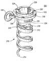
- FIG. 2is a simplified perspective view of an illustrative embodiment of several representative components of an illustrative prosthesis in accordance with the invention.
- FIG. 3is a simplified perspective view of an illustrative embodiment of a component of prosthesis delivery and implanting apparatus or instrumentation in accordance with the invention.
- FIG. 4is a simplified perspective view of an illustrative embodiment of another component of prosthesis delivery and implanting apparatus in accordance with the invention.
- FIG. 5is generally similar to FIG. 2 , but with the components shown in FIGS. 3 and 4 added.
- FIG. 6is a simplified perspective view of an illustrative embodiment of another representative component of an illustrative prosthesis in accordance with the invention.
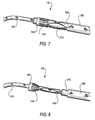
- FIG. 7is a simplified elevational view of an illustrative embodiment of representative components of an illustrative prosthesis, with illustrative apparatus for delivering and implanting one of those components, all in accordance with the invention.
- FIG. 8is similar to FIG. 7 , but shows a subsequent stage in use of what is shown in FIG. 7 in accordance with the invention.
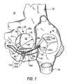
- FIG. 9is similar to FIG. 1 , but shows an illustrative embodiment of some of the instrumentation that can be used in the implanting of a prosthesis in accordance with the invention.
- FIG. 10is similar to FIG. 9 , but shows a later stage in use of what is shown in FIG. 9 in accordance with the invention.
- FIGS. 9 and 10show all heart structures the same size as FIG. 1 . It will be understood, however, that in actual practice the annulus of a patient's mitral valve will typically be larger prior to implanting a prosthesis in accordance with this invention. In other words, in actual practice the mitral valve annulus will be larger in FIGS. 9 and 10 (prior to prosthesis implanting) than in FIG. 1 (after completion of the prosthesis implanting).)
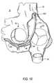
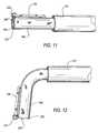
- FIG. 11is a simplified elevational view of an illustrative embodiment of representative components of an illustrative prosthesis, with illustrative apparatus for delivering and implanting those components, all in accordance with the invention.
- FIG. 12is similar to FIG. 11 , but shows a subsequent stage in use of what is shown in FIG. 11 .
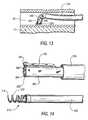
- FIG. 13is a simplified sectional view of a portion of what is shown in FIGS. 1, 9, and 10 at a particular, relatively early stage in implanting a prosthesis in accordance with the invention.
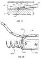
- FIG. 14is a simplified perspective view of an illustrative embodiment of representative components of an illustrative prosthesis, with illustrative apparatus for delivering and implanting those components, all in accordance with the invention.
- FIGS. 15-17are similar to FIG. 13 for successive subsequent stages in implanting a prosthesis in accordance with the invention.
- FIG. 18is generally similar to FIG. 14 , but with certain components additionally assembled in accordance with the invention.
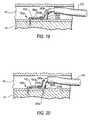
- FIGS. 19-23are again similar to FIGS. 13 and 15-17 , but show successive, more subsequent stages in implanting a prosthesis in accordance with the invention.
- FIG. 24is a simplified cross sectional view of another portion of what is shown in FIGS. 1, 9, and 10 at a particular intermediate stage in implanting a prosthesis in accordance with the invention.
- FIGS. 25-32are similar to FIG. 24 , but show successive, more subsequent stages in implanting a prosthesis in accordance with the invention.
- FIG. 33is a simplified cross section of an illustrative embodiment of certain components in accordance with the invention.
- FIG. 34is similar to FIG. 32 , but shows another illustrative embodiment of the invention.
- the inventionwill first be illustratively described primarily with reference to an embodiment for performing percutaneous mitral valve repair (“PMVR”). Later in this specification examples of possible alternatives to the first-described embodiment will be described, as will examples of some other possible uses of the invention.
- PMVRpercutaneous mitral valve repair
- FIG. 1left atrium 20 , right atrium 30 , superior vena cava 32 , inferior vena cava 34 , coronary sinus 40 , ostium 42 of coronary sinus 40 (opening into right atrium 30 ), and mitral valve 50 (including anterior leaflet 52 , posterior leaflet 54 (having three segments P 1 , P 2 , and P 3 ), annulus 56 , commissures 58 a and 58 b , and trigones 59 a and 59 b ).
- the anterior-posterior dimension of mitral valve 50is labeled AP.
- FIG. 1Heart 10 is shown in FIG. 1 with a prosthesis 100 implanted in it in accordance with certain aspects of the invention.
- Prosthesis 100includes a first anchor structure 110 that has been implanted in coronary sinus 40 outside posterior mitral valve segment P 2 .
- Prosthesis 100further includes a second anchor structure 120 that has been implanted in right atrium 30 outside the ostium 42 of coronary sinus 40 .
- Prosthesis 100still further includes a linking member 130 that extends between anchor structures 110 and 120 , and that is tensioned to pull those anchor structures toward one another.
- a clamp 140 on linking member 130 just proximal to anchor structure 140keeps anchor structures 110 and 120 at the desired spacing from one another along linking member 130 .
- anchor structure 110includes two screws 150 a and 150 b (only the head portions of these screws are actually visible in FIG. 1 ).
- the distal end of linking member 130is secured to distal-most screw 150 a at or adjacent the head of that screw.
- Spacer member 160 ais disposed around linking member 130 immediately proximal to screw 150 a .
- Linking member 130passes through an eyelet (not visible in FIG. 1 , but shown in later FIGS.) that is mounted on screw 150 b adjacent its head.
- the length of spacer member 160 ais approximately equal to the spacing of screws 150 a and 150 b along linking member 130 .
- Spacer member 160 acan be longer or shorter than is shown in FIG. 1 to provide a favorable angle to screws 150 a and 150 b.
- Anchor structure 120also includes two screws 150 c and 150 d (again, only the heads being actually visible in FIG. 1 ).
- Linking member 130passes through an eyelet (again, not visible in FIG. 1 , but shown in later FIGS.) that is mounted on screw 150 c adjacent its head.
- Proximal to the eyelet on screw 150 clinking member 130 passes through another spacer member 160 b , and then through an eyelet on screw 150 d (similar to the eyelet on screw 150 c ).
- the length of spacer member 160 bis approximately equal to the spacing of screws 150 c and 150 d along linking member 130 .
- spacer member 160 bcan be longer or shorter than is shown in FIG. 1 to provide a favorable angle to screws 150 c and 150 d .
- Clamp structure 140is mounted on linking member 130 immediately proximal to the above-mentioned eyelet on proximal-most screw 150 d.
- Screws 150 a and 150 bhave been driven through the wall of coronary sinus 40 into adjacent heart muscle tissue (preferably in the direction of mitral valve annulus 56 , and even more preferably into tissue of that annulus). Screws 150 c and 150 d are driven into heart muscle tissue of right atrium 30 .
- the above-mentioned Hindrichs et al. referencediscusses in detail preferred locations of anchor structures like structures 110 and 120 (although the anchor structures shown herein are new in at least some respects).
- the Hindrichs et al. referencealso discusses tissue structures that anchor structures like 110 and 120 preferably penetrate. All of these principles from the Hindrichs et al. reference are equally applicable to the present invention.
- FIG. 1further shows that the two screws 150 a and 150 b that form part of anchor structure 110 are preferably spaced from one another approximately along the longitudinal axis of linking member 130 .
- This axismay sometimes be referred to herein as the tension axis of prosthesis 100 .
- screws 150 c and 150 dare preferably driven into tissue transverse to the tension axis.
- driving screws 150 approximately perpendicular to the tension axisis highly desirable but not a requirement for all embodiments of the invention, as long as the screws are transverse to the tension axis to a significant and meaningful degree.
- both screws 150 in each pair of screwstend to remain transverse to the tension axis.
- the screw 150 b or 150 c in each pair that is closer to the other pairmay act through the associated spacer member 160 a or 160 b to brace or buttress the other screw 150 a or 150 d in that pair and thereby help the buttressed screw from becoming aligned with the tension axis.
- a screw that is driven into tissue and remains transverse to the tension axisprovides much stronger holding of the tissue than a screw that can rotate into alignment with the tension axis.
- An anchor structure (e.g., 110 or 120 ) including two screws in accordance with this inventionis more than twice as strong as a single-screw anchor structure of prior known construction. Moreover, this much stronger anchor structure can be delivered (e.g., percutaneously) through catheter apparatus that is no larger in diameter than would be required for delivery of a single-screw anchor structure of prior known construction.
- Screw 150is actually an assembly of three components: threaded component 210 , collar 230 , and ring 240 .
- Components 210 , 230 , and 240may be made of any suitable bio-compatible material such as 316L stainless steel, L605, Elgiloy, MP35N, gold, platinum, platinum 10 iridium, platinum 20 iridium, titanium, Nitinol, tantalum, niobium, tungsten, Carpenter CCM, a polymer, another material coated with a polymer, etc.
- One or more of these componentsmay have drug coating(s) and/or be drug eluting.
- one or more of the partsmay be plated with a high atomic density material such as gold, platinum, tantalum, or the like.
- a high atomic density materialsuch as gold, platinum, tantalum, or the like.
- One or more of the componentsmay also be clad with one or more layers, such as stainless steel clad with tantalum metal.
- Threaded component 210includes hollow, helical, corkscrew-like, screw portion 212 and hollow head portion 220 .
- Screw portion 212has a sharply pointed distal tip 214 to facilitate tissue penetration by the screw.
- Proximal of distal tip 214screw portion 212 has several helical turns that lead back to head portion 220 . These turns may include one or more barbs 216 to resist unthreading of the screw from tissue into which it has been threaded.
- each barb 216is attached to screw portion 212 closer to distal tip 214 and is inclined out and away from the screw portion farther from the distal tip.
- each barb 216is anticlinal from screw portion 212 in the direction opposite the direction in which the screw portion is driven into tissue.
- Head portion 220is basically a hollow cylinder with a flange 222 extending radially outwardly from the proximal end of the cylinder. All portions of screw component 210 other than flange 222 are small enough to pass freely through collar 230 . Flange 222 cannot pass through collar 230 . Head portion 220 includes features that are usable to releasably hold screw component 210 on screw driving apparatus (not shown in FIG. 2 , but detailed later in this specification). These features comprise three approximately T-shaped cut-outs or recesses 224 in head portion 220 . These recesses are accessible from the hollow interior of head portion 220 , and they are equidistantly spaced around the circumference of the head portion.
- Collar 230fits loosely around the outside of head portion 220 , but, as mentioned earlier, flange 222 is too large to pass through the collar. Accordingly, screw component 210 is rotatable about its longitudinal axis relative to collar 230 , but when screw 150 is driven into tissue, collar 230 is trapped or captured on the screw by flange 222 . Collar 230 includes features that are usable to releasably hold the collar on apparatus that is used to implant screw 150 in a patient. These features are recesses or apertures 232 in or through collar 230 . Collar 230 also has a larger aperture 234 for loosely capturing ring 240 .
- Ring 240is large enough for linking member 130 to pass freely through the ring.
- ring 240may be omitted from distal-most screw 150 a so that the distal end of linking member 130 can be attached directly to aperture 232 on the collar 230 of that screw.
- linking member 130preferably passes freely through the rings 240 on those screws.
- FIG. 3shows a component of apparatus that can be used for releasably holding and driving a screw 150 of the type shown in FIG. 2 .
- This screw holder/driver component 250includes a hollow-cylindrical proximal portion 252 and three distally extending T-shaped portions 254 .
- Proximal portion 252includes a plurality of apertures 256 that are usable to help connect screw holder/driver 250 to apparatus components upstream from the holder/driver in a manner that facilitates transmission of torque from those upstream components to holder/driver 250 .
- the component immediately upstream from holder/driver 250is typically a torqueable flexible shaft (not shown in FIG. 3 , but visible in FIG. 14 ).
- T-shaped portions 254are shaped, sized, and located to fit somewhat loosely into the T-shaped cut-outs or recesses 224 in the head portion 220 of a screw 150 .
- T-shaped portions 254are resiliently biased to deflect radially inwardly toward one another. When thus deflected radially inwardly, the enlarged, distal, free end parts of T-shaped portions 254 can pass freely into or out of the hollow cylindrical head 220 of a screw 150 .
- T-shaped portions 254can be deflected radially outwardly to the positions shown in FIG. 3 by inserting a properly sized cylindrical member (not shown in FIG. 3 ) into the interior of component 250 .
- T-shaped portions 254fit into T-shaped cut-outs or recesses 224 in the head portion of a screw 150 .
- the above-mentioned cylindrical membercan be withdrawn from the interior of holder/driven 250 . This allows the enlarged distal ends of T-shaped fingers 254 to deflect inwardly and thereby exit from the corresponding portions of T-shaped recesses 224 in the screw. The screw is therefore no longer held on the apparatus by inter-engagement of elements 224 and 254 .
- the particular structure shown and described above for releasably holding screw 150 on holder/driver 250is only one example of many possible ways that this function can be achieved.
- features like 224 and 254could have many other complementary shapes that would serve the purposes of releasably holding components 150 and 250 together and permitting the transmission of torque from component 250 to component 150 while those components are held together.
- the cylindrical member mentioned in the preceding paragraphmay be used as a depth gauge for the driving of the associated screw. For example, when the distal end of this cylindrical member reaches the surface of the tissue, it is thereby known that the associated screw has been driven far enough into the tissue. Indeed, the structure may be arranged so that the tissue pushes the cylindrical member out of the screw, thereby decoupling the screw from its holder 250 and automatically stopping further driving of the screw at the proper depth of tissue penetration.
- FIG. 4shows a component of apparatus that can be used to releasably hold a screw collar 230 of the type shown in FIG. 2 .
- This collar holder 260includes a hollow cylindrical proximal portion 262 and three distally extending gripper fingers 264 .
- Proximal portion 262can fit concentrically but loosely around the outside of holder/driver 250 ( FIG. 3 ).
- Proximal portion 262includes a plurality of apertures 266 that are usable to help connect collar holder 260 to upstream apparatus components. Fingers 264 fit into apertures 232 in collar 230 . In the radial direction this fit is preferably loose.
- FIG. 5shows an assembly of the elements that are shown individually in FIGS. 2-4 .
- Screw component 210is releasably retained on holder/driver component 250 by the presence of T-shaped portions 254 of component 250 in complementary recesses 224 in the head portion 220 of screw portion 210 .
- the presence of T-shaped portions 254 in recesses 224also makes it possible to rotate screw component 210 about its longitudinal axis by rotating holder/driver component 250 about that axis.
- Collar 230is releasably retained on collar holder 260 by the force-fitted presence of fingers 264 from holder 260 in collar apertures 232 .
- Components 210 and 250are rotatable relative to components 230 and 260 about the longitudinal axis of component 210 .
- FIG. 5omits the apparatus component that is required to keep T-shaped portions 254 deflected radially outward and therefore in recesses 224 as shown in FIG. 5 .
- the free ends of fingers 264preferably extend completely through and beyond the lower surface of collar 230 . This permits the free ends of fingers 264 to engage or penetrate the surface of the tissue into which threaded portion 210 is going to be driven.
- Such engagement or penetrationhelps to stabilize the assembly at a desired location on the surface of the tissue during driving of threaded portion 210 , and also prevents collar 230 from undesirably rotating with threaded portion 210 as the threaded portion is rotated to drive it into the tissue.
- FIG. 6shows an illustrative embodiment of a typical spacer member 160 in more detail.
- a spacer member 160can be a hollow cylinder (e.g., of a bio-compatible metal).
- the hollow center of spacer member 160is preferably large enough to allow the spacer member to slide freely along the length of linking member 130 .
- the diameter of spacer member 160should be large enough so that the ends of the spacer member can engage the head portions of screws 150 that the spacer member abuts.
- Spacer member 160may have features beyond those shown in FIG. 6 .
- spacer member 160may have perforations, a dacron cover, and/or other features to promote tissue in-growth and anchoring in the patient.
- Suitable materials for spacer member 160include those mentioned above for components 210 , 230 , and 240 .
- clamp structure 140Still another component of the apparatus is clamp structure 140 .
- An illustrative embodiment of clamp structure 140is shown in FIGS. 7 and 8 , with some other apparatus also visible.
- clamp structureis disposed concentrically around a hollow tube 270 through which linking member 130 passes loosely.
- tube 270has been removed to release clamping structure 140 to engage linking member 130 .
- the distal directionis to the left in FIGS. 7 and 8 . This is consistent with FIG. 1 .
- Clamp structure 140(e.g., of bio-compatible metal) is resiliently biased to assume the shape shown in FIG. 8 , but it can be elastically deflected to the shape shown in FIG. 7 . (Alternatively clamping structure 140 could be plastically deformed from the shape shown in FIG. 7 to the shape shown in FIG. 8 .) Proceeding from left to right in FIG. 7 , clamp structure 140 includes (1) a hollow cylindrical portion 142 , (2) a plurality of relatively short fingers 144 that extend in the proximal direction from cylindrical portion 142 and that are resiliently biased to deflect inwardly, and a (3) plurality of relatively long fingers 146 that also extend in the proximal direction from cylindrical portion 142 and that are intercalated with fingers 144 .
- Proximal free end portions of fingers 146are also resiliently biased to deflect inwardly.
- the inward bias of fingers 144 and 146helps to hold clamp structure 140 on tube 270 , albeit in such a way that tube 270 can be withdrawn from structure 140 when desired.
- the proximally directed free ends of fingers 144are preferably sharp enough to dig into linking member 130 when tube 270 is withdrawn from inside structure 140 (see FIG. 8 ). This prevents clamp structure 140 from moving proximally along linking member 130 once structure 140 has thus engaged member 130 .
- This resistance to movement of structure 140may be facilitated or enhanced by making linking member 130 of braided suture material as shown in FIGS. 7 and 8 , but other constructions of linking member 130 are also possible, as will be further discussed later in this specification.
- proximally directed free ends of fingers 146are less sharp and are intended to press inwardly on linking member 130 for such purposes as to stabilize clamp structure 140 on linking member and to prevent a braided linking member 130 from unraveling when it is subsequently cut proximal to clamp structure 140 .
- An illustrative methodbegins with inserting an introducer tube 300 into the superior vena cava 32 of the patient as shown in FIG. 9 . This may be done by starting from an introduction point into the patient along the patient's jugular vein. A possible alternative approach is via inferior vena cava 34 . Either of these approaches gives access to right atrium 30 . Although the distal end of introducer 300 is shown relatively low in FIG. 9 , it may actually be higher and therefore out of sight in what is shown in that FIG.
- the next step in the illustrative method being discussedis to insert a guide catheter or sheath 310 into the patient via introducer 300 and to extend that guide catheter into the ostium 42 of coronary sinus 40 as is also shown in FIG. 9 .
- the next stepis to extend an obturator or dilator 320 and a wire 330 into guide catheter 310 and then from the distal end of the guide catheter farther into coronary sinus 40 (continue to see FIG. 9 ).
- Obturator 320provides support for wire 330 to help the distal-most portion of the wire extend into coronary sinus 40 , and possibly into a tributary thereof, well beyond the point at which the distal anchor structure 110 of prosthesis 100 will be implanted.
- the next step(illustrated by FIG. 10 ) is to advance guide catheter 310 to the desired location of distal anchor structure 110 .
- Obturator 320is removed at this time.
- the next stepis to introduce into guide catheter 310 and “over” wire 330 a delivery system for the first part of distal anchor structure 110 .
- thisis a delivery system for implanting screw 150 a .
- FIG. 11shows a first part of this delivery system extending from the distal end of guide catheter 310 .
- no tissueis shown in FIG. 11 .
- This FIG.also omits wire 330 , although it will be understood that in actual use wire 330 may be present.
- the portion of the delivery system shown in FIG. 11includes tubular member 340 extending from the distal end of guide catheter 310 .
- a collar holder 260(not visible in FIG.
- linking member 130(which extends from a side lumen 341 of tubular member 340 (see FIG. 33 )) is secured to ring 240 on collar 230 .
- ring 240could be omitted, and the distal end of linking member 130 could be secured directly to the aperture 234 in collar 230 that ring 240 is shown passing through.
- a proximal portion of linking structure 130preferably passes along the side lumen 341 of tubular member 340 upstream from what is shown in FIG.
- Wire 330(not shown in FIG. 11 ) can extend from the distal end of the assembly of elements 340 / 260 / 230 to its distal end to the left of what is shown in FIG. 11 . Wire 330 can be withdrawn once the elements shown in FIG. 11 have reached the desired location along coronary sinus 40 (or the wire could be withdrawn earlier, e.g., after the distal end of guide catheter 310 has reached its desired location along coronary sinus 40 as shown in FIG. 10 ).
- the distal portion of tubular member 340is “steerable” (see FIG. 12 ). This means that the distal portion of tubular member 340 can be controllably deflected transverse to the longitudinal axis of guide catheter 310 (or to the longitudinal axis of the proximally adjacent portion of tubular member 340 ). The amount of this deflection is preferably up to about 90° or more. In other words, the distal portion of tubular member 340 can be deflected so that it becomes substantially perpendicular to the proximally adjacent portion of that member. This allows the distal portion of tubular member 340 to be aimed at the side wall of coronary sinus 40 as shown in FIG. 13 .
- tubular member 340may be unidirectional, bidirectional, or multidirectional (in other words, in one direction transverse to the longitudinal axis of the remainder of the structure, in either of two directions transverse to that longitudinal axis, or in any one of several directions transverse to that longitudinal axis).
- the relative sizes and shapes of the tissue and apparatus componentsmay be such that transverse deflection of the distal portion of the structure causes a substantial distortion of coronary sinus 40 at that location.
- the “back” side of the apparatusi.e., adjacent the bend in tubular member 340
- the same kind of distortion of coronary sinus 40may occur in connection with FIG. 19 , although this distortion is again not actually shown in that FIG.)
- FIG. 14Further components of the delivery system for implanting screw 150 a are shown in FIG. 14 . These components include tubular member 350 with a screw holder/driver attached to its distal end and threaded component 210 held on that holder/driver. Another tube or plug (not visible) is disposed coaxially inside elements 350 and 250 to initially keep T-shaped portions 254 of holder/driver 250 deflected radially outward in the complementary recesses 224 in threaded component 210 and thereby hold threaded component 210 on holder/driver 250 .
- Components 350 / 250 / 210are insertable coaxially into and along tubular member 340 from the proximal end of member 340 .
- Components 350 / 250 / 210may be inside member 340 when member 340 is inserted into guide catheter 310 .
- tubular member 350may be pushed distally and rotated about its longitudinal axis to cause threaded portion 210 to begin to emerge from the distal end of assembly 340 / 260 / 230 and to begin to threadedly penetrate the side wall of coronary sinus 40 and adjacent heart tissue 41 (see FIG. 15 ).
- components 310 and/or 340preferably bear on the wall of coronary sinus 40 approximately opposite the tissue-entry point of threaded portion 210 to help force threaded portion 210 into the tissue.
- Component 350is preferably sufficiently laterally flexile to follow the lateral (steering) deflection of component 340 .
- Component 350is also able to transmit to component 210 the torque necessary to thread component 210 into tissue.
- Screw 150 ais now implanted in tissue 40 / 41 and fully released from delivery apparatus 340 / 260 / 350 / 250 , although the screw is still attached to the distal end of linking member 130 .
- the next stepis to re-straighten the steerable distal portion of tubular member 340 and withdraw components 340 , 360 , 350 , and 250 from the patient.
- the condition of the apparatusis now as shown in FIG. 16 .
- the next stepis to push spacer member 160 a into the patient over linking member 130 .
- a proximal portion of linking member 130may transition from a suture-like material to a wire to facilitate getting spacer member 160 a (and other apparatus) into the patient over linking member 130 .
- a tubular pusher 370may be placed over linking member 130 proximal to spacer member 160 a for use in pushing spacer member 160 a into the patient and into abutment with screw 150 a as shown in FIG. 17 .
- tubular pusher 370may be withdrawn from the patient.
- the next stepis to position the distal end of guide catheter 310 appropriately for implanting second screw 150 b .
- Apparatus for delivering second screw 150 bcan then be inserted into the patient via guide catheter 310 .
- the delivery system for second screw 150 bcan be very similar to the above-described delivery system for first screw 150 a .
- the only significant differenceis that in the case of second screw 150 b linking member 130 passes loosely through the ring 240 of the second screw rather than being secured to the screw as in the case of first screw 150 a .
- FIG. 18illustrates this type of loose passage of linking member 130 through a ring 240 on a screw 150 like screw 150 b.
- the delivery system for screw 150 bcan be so similar to the delivery system for screw 150 a , the same reference numbers will be used again (but with a “b” suffix) for components of the second screw delivery system. Discussion of delivery and implanting of the second screw can also be somewhat abbreviated because it is so similar to the above-described delivery and implanting of the first screw.
- FIG. 19shows the condition of the apparatus after components 340 b , 260 b , and 230 b for second screw 150 b have been extended from the distal end of guide catheter 310 and steered (i.e., laterally deflected) toward the desired point on the side wall of coronary sinus 40 .
- Passage of linking member 130 through ring 240 bis facilitated by the above-mentioned proximal wire end portion of linking member 130 , which remains outside the patients body and is available for use in helping to place successive components and instrumentalities on linking member 130 .
- the threaded portion 210 b of second screw 150 bcan be advanced distally through assembly 340 b / 260 b / 230 b and driven into tissue 40 / 41 as described above for the corresponding components associated with screw 150 a (see FIG. 20 ).
- threaded portion 210 bAfter threaded portion 210 b has been driven into tissue 40 / 41 , threaded portion 210 b can be released from its holder/driver (not visible, but inside tubular member 340 b ) as described earlier for the corresponding parts associated with screw 150 a . Then collar 230 b can be released from its holder 260 b in the same manner as described above for the corresponding parts associated with screw 150 a . The distal end of tubular member 340 b can be re-straightened, and all of the delivery apparatus for screw 150 b can be proximally withdrawn from the patient via guide catheter 310 . The condition of the apparatus is now as shown in FIG. 21 .
- FIGS. 22 and 23clamp structure 140 a and associated delivery apparatus (e.g., as shown in more detail in FIG. 7 ) is loaded onto linking member 130 and introduced into the patient via guide catheter 310 .
- the delivery apparatus for clamp 140 aincludes a tube 270 inside the clamp (see FIG. 7 ) and another tubular member 380 disposed concentrically around the outside of tube 270 and bearing (at its distal end) on the proximal end of the clamp.
- FIG. 22shows clamp 140 a pushed up against structure of screw 150 b and therefore ready for release onto linking member 130 .
- Clamp 140 ais released onto linking member 130 by pulling back on tube 270 while holding tubular member 380 stationary (see also FIG. 8 ). Proximal withdrawal of tube 270 allows the various fingers 144 and 146 to engage member 130 as described earlier in connection with FIG. 8 . Tubes 270 and 380 can then be completely withdrawn from the patient, leaving the apparatus as shown in FIG. 23 .
- the presence of clamp 140 a pressing distally on the structure of proximal screw 150 bmay help to stiffen and strengthen distal anchor structure 110 (including screws 150 a and 150 b and spacer 160 a ). However, use of clamp 160 a is optional.
- the next stepis to retract guide catheter 310 into the patient's right atrium 30 (see FIG. 24 ).
- the distal end of guide catheter 310is placed near the desired location of third screw 150 c .
- Delivery and implanting of third screw 150 ccan be similar (except for location) to delivery and implanting of second screw 150 b . Accordingly, the description for third screw 150 c can be somewhat abbreviated.
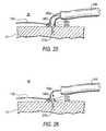
- FIG. 24shows the apparatus after the distal end of the delivery system for third screw 150 c has been steered (deflected laterally) toward the desired implant site for screw 150 c in the tissue 31 of right atrium 30 .
- Hindrichs et al. referencediscusses preferred locations for a proximal tissue anchor.
- the proximal anchor placement principles discussed thereare equally applicable to placing screw 150 c in accordance with this invention. Those principles are preferably followed in locating and implanting screw 150 c (and screw 150 d ) in practicing the present invention. As shown in FIG.
- delivery system components 340 c and 260 c for third screw 150 cposition the collar 230 c for the third screw against the surface of heart tissue 31 at the desired location.
- Linking member 130comes from above-described distal anchor 110 (out of sight to the left in FIG. 24 ), passes through the ring 240 c on collar 230 c , and enters tubular member 340 c.
- tubular member 340 ccan be passive deflection (i.e., a shape that is remembered by member 340 c once that member is out of guide catheter 310 ).
- passive deflectioni.e., a shape that is remembered by member 340 c once that member is out of guide catheter 310 .
- pull wiresmay be needed to generate more deflecting force and deform the coronary sinus.
- tissue deformationmay not be involved, and so passive steering deflection of tubular member 340 c may be sufficient. (The same may be true for tubular member 340 d , described below.)
- Threaded portion 210 c of that screwis driven (by other delivery system components that are inside components 340 c and 260 c and that are similar to components 350 and 250 ( FIG. 14 )) through collar 230 c and into tissue 31 as shown in FIG. 25 .
- Threaded portion 210 cis then released from its holder/driver, collar 230 c is released from its holder 260 c , and the delivery system for screw 150 c is re-straightened and withdrawn from the patient via guide catheter 310 .
- the condition of the apparatusis now as shown in FIG. 26 .
- the next stepis to insert spacer 160 b into the patient along linking member 130 until it abuts the proximal side of screw 150 c .
- This stepis so similar to the insertion of spacer 160 a that it does not need to be separately illustrated or further described.
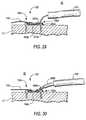
- the next stepis to reposition the distal end of guide catheter 310 for implanting of fourth screw 150 d .
- the fourth screw and its delivery systemare inserted into guide catheter 310 over linking member 130 .
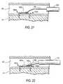
- the distal end of the delivery system 340 d for fourth screw 150 dis then steered toward tissue 31 just proximal to screw 150 c and spacer 160 b as shown in FIG. 27 . Again, this steering may be passive as in the case of delivery system 340 c.
- the next step, illustrated by FIG. 28is to drive the threaded portion 210 d of screw 150 d through collar 230 d and into tissue 31 .
- threaded portion 210 dis released from its holder/driver apparatus (not visible, but similar to previously shown and described components of the same kind), and collar 230 d is released from its holder 260 d .
- Delivery system 340 dis then re-straightened and withdrawn from the patient via guide catheter 310 .
- the condition of the apparatusis now as shown in FIG. 29 .
- the next stepis to introduce a second clamp 140 b into the patient on second clamp delivery apparatus 380 b (see FIG. 30 ). This is again done via guide catheter 310 and with all of elements 380 b and 140 b around the portion of linking member 130 that is proximal to proximal anchor structure 120 .
- linking structure 130 and structure 140 b / 380 bcan be used to shorten the distance between anchor structures 110 and 120 to any desired degree. This can be done by pulling proximally on the proximal end of linking structure 130 (outside of the patient) while pushing distally on components 140 b / 380 b (also from outside the patient).
- the amount of spacing between distal and proximal anchor structures 110 and 120is adjustable in both directions until clamp 140 b is launched. This means that different spacings can be tried until the best spacing is found. Even if the spacing is initially decreased too much, that can be reversed by allowing the spacing to increase again. Clamp 140 b is launched only after the best spacing has been found. It should also be noted that in this embodiment the spacing between anchor structures 110 and 120 is “infinitely adjustable” (within, of course, the practical range for such spacing). This means that within the practical range, the prosthesis can select and maintain any desired spacing between anchor structures 110 and 120 .
- the preceding paragraphrefers to the possibility of trying different spacings of anchor structures 110 and 120 until the best spacing is found.
- the best spacingmay be judged with the aid of any of a number of techniques such as direct visualization, fluoroscopy, echo cardiography, computed tomography, MRI, hemodynamic monitoring techniques, etc.
- clamp 140 bAfter clamp 140 b has been launched, the next step is to cut linking structure 130 proximal to clamp 140 b and to remove everything that is proximal to the cut.
- the condition of the apparatusis now as shown in FIG. 32 (and also FIG. 1 ). The process of implanting the prosthesis is complete and all delivery apparatus can be withdrawn from the patient.
- a possible variation on the above methodis to install the prosthesis as described above with little or no significant shortening of the distance between anchor structures 110 and 120 .
- the prosthesisacts as a precaution or prophylactic against possible future weakening and distension of the mitral valve annulus in the portion of that annulus that is spanned by the prosthesis.
- FIG. 34Another possible variation on the above-described methods and apparatus is illustrated by FIG. 34 .
- the prosthesisis implanted as described above (with or without shortening of the distance between anchor structures 110 and 120 ). Some of linking member 130 is left proximal to clamp 140 b .
- the patientcan be re-entered to change or further change the spacing between anchor structures 110 and 120 .
- the re-entry apparatusmay include catheter 410 , which can be introduced into the patient percutaneously in the same way that other apparatus described above can be introduced.
- Catheter 410is used to deliver snare structure 420 / 430 into the patient adjacent to the proximal end of linking member 130 .
- Snare loop 430is deployed and snares the proximal end of linking member 130 .
- Linking member 130may have been left with a proximal enlargement 132 to facilitate good engagement by snare loop 430 .
- Enlargement 132may be radio-opaque to facilitate finding it in the patient.
- Snare loop 430is used to hold the end of linking structure 130 while snare tube 420 is pushed distally onto linking structure 130 .
- snare tube 420When the distal end of snare tube 420 reaches clamp 160 b , snare tube 420 can be used to push that clamp distally along linking member 130 , while snare loop 430 is pulled proximally to hold linking member 130 in place. In this way the distance between anchor structures 110 and 120 can be shortened or further shortened at any time after the prosthesis has been implanted. When the desired shortening or further shortening has been achieved, linking member 130 can be released from snare loop 430 and apparatus 410 / 420 / 430 can be withdrawn from the patient. Clamp 140 b will maintain the prosthesis with whatever spacing has been set between anchor structures 110 and 120 .
- Embodiments of the type illustrated by FIG. 34may be desirable because they can take advantage of the fact that anchor structures 110 and 120 tend to be stronger after the tissue in which they are implanted has healed.
- the prosthesiscan be initially implanted with little or no shortening of the distance between anchor structures 110 and 120 , and therefore with little or no tension in linking member 130 . There is therefore little or no force acting on the anchor structures that might tend to pull them from the tissue. After the tissue has healed, the anchor structures are stronger than they are when first implanted. The technique and apparatus illustrated by FIG. 34 can then be used to tension linking member 130 and shorten the distance between anchor structures 110 and 120 . Because the tissue at the anchor structures has already healed when this is done, the prosthesis is even more secure than it otherwise would have been.
- each screw 210could be held on its holder 250 by structures 254 ( FIG. 3 ) that are resiliently biased to deflect outwardly rather than inwardly as described above.
- Each ring 240e.g., FIG. 2
- FIG. 2could be integrated into the associated collar 230 rather than being a separate component.
- Each of anchor structures 110 and 120could be on a separate linking member like 130 , with both of those linking members pulled through a common final clamp (like 140 b ) to pull the two anchor structures together.
- the above-mentioned Hindrichs et al. referenceshows this type of use of two strands pulled through a common final clamp.
- One or more of anchor structures 110 and 120can be (or can include) a tissue-piercing lead for any type of electrical apparatus.
- Linking member 130can be or can be part of an electrical conductor that is electrically connected to the tissue-piercing lead. This conductor can extend to other electrical apparatus inside and/or outside the patient.
- any portion or portions of the prosthesiscan have one or more coatings for biological purposes such as to reduce inflammatory response, promote healing, reduce clotting or thrombogenicity response, etc. For example, this may be accomplished by using one or more polymer coatings that can elute one or more drugs or medications.
- Linking member 130can have radio-opaque markers at predetermined spacings or locations to help visualize the amount of shortening between an chor structures 110 and 120 that is being achieved. Any of the materials and/or material constructions mentioned anywhere throughout this specification can be used for any component or components of the prosthesis, as is appropriate for that component or for those components.
- screw structures 150 of the types shown and described hereinhave features that may permit effective use of only one such screw (rather than a pair) as an anchor structure such as 110 and/or 120 in a prosthesis in accordance with this invention.
- collar 230may act as a washer that bears on the surface of tissue and helps to reduce tipping of a single screw structure 150 when that structure is pulled on by the linking member 130 of a prosthesis.
- the fact that the point of attachment of linking member 130 to screw structure 150 is on collar 230 (which is at or close to the tissue surface rather than at the top of the screw structure) and off the central longitudinal axis of screw structure 150may further help to reduce tipping of a single screw structure when pulled by the linking member.
Landscapes
- Health & Medical Sciences (AREA)
- Life Sciences & Earth Sciences (AREA)
- Cardiology (AREA)
- General Health & Medical Sciences (AREA)
- Veterinary Medicine (AREA)
- Biomedical Technology (AREA)
- Heart & Thoracic Surgery (AREA)
- Vascular Medicine (AREA)
- Engineering & Computer Science (AREA)
- Animal Behavior & Ethology (AREA)
- Surgery (AREA)
- Public Health (AREA)
- Transplantation (AREA)
- Reproductive Health (AREA)
- Nuclear Medicine, Radiotherapy & Molecular Imaging (AREA)
- Oral & Maxillofacial Surgery (AREA)
- Medical Informatics (AREA)
- Molecular Biology (AREA)
- Prostheses (AREA)
- Surgical Instruments (AREA)
Abstract
Description
Claims (28)
Priority Applications (4)
| Application Number | Priority Date | Filing Date | Title |
|---|---|---|---|
| US11/215,341US9492277B2 (en) | 2005-08-30 | 2005-08-30 | Soft body tissue remodeling methods and apparatus |
| DE602006011092TDE602006011092D1 (en) | 2005-08-30 | 2006-08-11 | Device for remodeling soft body tissue |
| EP06016818AEP1759663B1 (en) | 2005-08-30 | 2006-08-11 | Soft body tissue remodeling apparatus |
| AT06016818TATE451892T1 (en) | 2005-08-30 | 2006-08-11 | DEVICE FOR REMODELING SOFT BODY TISSUE |
Applications Claiming Priority (1)
| Application Number | Priority Date | Filing Date | Title |
|---|---|---|---|
| US11/215,341US9492277B2 (en) | 2005-08-30 | 2005-08-30 | Soft body tissue remodeling methods and apparatus |
Publications (2)
| Publication Number | Publication Date |
|---|---|
| US20070049942A1 US20070049942A1 (en) | 2007-03-01 |
| US9492277B2true US9492277B2 (en) | 2016-11-15 |
Family
ID=37433689
Family Applications (1)
| Application Number | Title | Priority Date | Filing Date |
|---|---|---|---|
| US11/215,341Active2031-02-13US9492277B2 (en) | 2005-08-30 | 2005-08-30 | Soft body tissue remodeling methods and apparatus |
Country Status (4)
| Country | Link |
|---|---|
| US (1) | US9492277B2 (en) |
| EP (1) | EP1759663B1 (en) |
| AT (1) | ATE451892T1 (en) |
| DE (1) | DE602006011092D1 (en) |
Families Citing this family (182)
| Publication number | Priority date | Publication date | Assignee | Title |
|---|---|---|---|---|
| WO2003105670A2 (en) | 2002-01-10 | 2003-12-24 | Guided Delivery Systems, Inc. | Devices and methods for heart valve repair |
| US20050107811A1 (en) | 2002-06-13 | 2005-05-19 | Guided Delivery Systems, Inc. | Delivery devices and methods for heart valve repair |
| US7753922B2 (en)* | 2003-09-04 | 2010-07-13 | Guided Delivery Systems, Inc. | Devices and methods for cardiac annulus stabilization and treatment |
| US9949829B2 (en) | 2002-06-13 | 2018-04-24 | Ancora Heart, Inc. | Delivery devices and methods for heart valve repair |
| US7883538B2 (en)* | 2002-06-13 | 2011-02-08 | Guided Delivery Systems Inc. | Methods and devices for termination |
| US7753858B2 (en)* | 2002-06-13 | 2010-07-13 | Guided Delivery Systems, Inc. | Delivery devices and methods for heart valve repair |
| US8287555B2 (en)* | 2003-02-06 | 2012-10-16 | Guided Delivery Systems, Inc. | Devices and methods for heart valve repair |
| US7666193B2 (en) | 2002-06-13 | 2010-02-23 | Guided Delivery Sytems, Inc. | Delivery devices and methods for heart valve repair |
| US7588582B2 (en)* | 2002-06-13 | 2009-09-15 | Guided Delivery Systems Inc. | Methods for remodeling cardiac tissue |
| US20060122633A1 (en)* | 2002-06-13 | 2006-06-08 | John To | Methods and devices for termination |
| US20060241656A1 (en)* | 2002-06-13 | 2006-10-26 | Starksen Niel F | Delivery devices and methods for heart valve repair |
| US7758637B2 (en)* | 2003-02-06 | 2010-07-20 | Guided Delivery Systems, Inc. | Delivery devices and methods for heart valve repair |
| US8641727B2 (en) | 2002-06-13 | 2014-02-04 | Guided Delivery Systems, Inc. | Devices and methods for heart valve repair |
| US7534204B2 (en)* | 2003-09-03 | 2009-05-19 | Guided Delivery Systems, Inc. | Cardiac visualization devices and methods |
| US20050273138A1 (en)* | 2003-12-19 | 2005-12-08 | Guided Delivery Systems, Inc. | Devices and methods for anchoring tissue |
| US7942927B2 (en) | 2004-03-15 | 2011-05-17 | Baker Medical Research Institute | Treating valve failure |
| US20080288060A1 (en)* | 2004-07-06 | 2008-11-20 | Baker Medical Research Institute | Treating Valvular Insufficiency |
| US8608797B2 (en) | 2005-03-17 | 2013-12-17 | Valtech Cardio Ltd. | Mitral valve treatment techniques |
| US8333777B2 (en) | 2005-04-22 | 2012-12-18 | Benvenue Medical, Inc. | Catheter-based tissue remodeling devices and methods |
| US8951285B2 (en) | 2005-07-05 | 2015-02-10 | Mitralign, Inc. | Tissue anchor, anchoring system and methods of using the same |
| US20070118151A1 (en)* | 2005-11-21 | 2007-05-24 | The Brigham And Women's Hospital, Inc. | Percutaneous cardiac valve repair with adjustable artificial chordae |
| WO2007136532A2 (en) | 2006-05-03 | 2007-11-29 | St. Jude Medical, Inc. | Soft body tissue remodeling methods and apparatus |
| US8388680B2 (en)* | 2006-10-18 | 2013-03-05 | Guided Delivery Systems, Inc. | Methods and devices for catheter advancement and delivery of substances therethrough |
| US11259924B2 (en) | 2006-12-05 | 2022-03-01 | Valtech Cardio Ltd. | Implantation of repair devices in the heart |
| AU2007330338A1 (en) | 2006-12-05 | 2008-06-12 | Valtech Cardio, Ltd. | Segmented ring placement |
| US9883943B2 (en) | 2006-12-05 | 2018-02-06 | Valtech Cardio, Ltd. | Implantation of repair devices in the heart |
| US8163019B2 (en)* | 2006-12-22 | 2012-04-24 | Pioneer Surgical Technology, Inc. | Implant restraint device and methods |
| US20080177380A1 (en)* | 2007-01-19 | 2008-07-24 | Starksen Niel F | Methods and devices for heart tissue repair |
| US11660190B2 (en) | 2007-03-13 | 2023-05-30 | Edwards Lifesciences Corporation | Tissue anchors, systems and methods, and devices |
| US9101357B2 (en)* | 2007-06-08 | 2015-08-11 | Board Of Trustees Of The University Of Arkansas | Physiologic abdominal closure |
| CA2781407A1 (en)* | 2008-01-14 | 2009-07-23 | Michael P. Brenzel | Apparatus and methods for fracture repair |
| US8790367B2 (en)* | 2008-02-06 | 2014-07-29 | Guided Delivery Systems Inc. | Multi-window guide tunnel |
| US8382829B1 (en) | 2008-03-10 | 2013-02-26 | Mitralign, Inc. | Method to reduce mitral regurgitation by cinching the commissure of the mitral valve |
| US8096985B2 (en) | 2008-05-07 | 2012-01-17 | Guided Delivery Systems Inc. | Deflectable guide |
| EP2296744B1 (en) | 2008-06-16 | 2019-07-31 | Valtech Cardio, Ltd. | Annuloplasty devices |
| US20100010538A1 (en)* | 2008-07-11 | 2010-01-14 | Maquet Cardiovascular Llc | Reshaping the mitral valve of a heart |
| JP2012505049A (en) | 2008-10-10 | 2012-03-01 | ガイデッド デリバリー システムズ, インコーポレイテッド | Tether tensioning device and related methods |
| BRPI0920406A2 (en) | 2008-10-10 | 2019-09-24 | Guided Delivery Systems Inc | termination devices and related methods. |
| US8940044B2 (en) | 2011-06-23 | 2015-01-27 | Valtech Cardio, Ltd. | Closure element for use with an annuloplasty structure |
| US8147542B2 (en) | 2008-12-22 | 2012-04-03 | Valtech Cardio, Ltd. | Adjustable repair chords and spool mechanism therefor |
| US10517719B2 (en) | 2008-12-22 | 2019-12-31 | Valtech Cardio, Ltd. | Implantation of repair devices in the heart |
| US8926697B2 (en) | 2011-06-23 | 2015-01-06 | Valtech Cardio, Ltd. | Closed band for percutaneous annuloplasty |
| US8808368B2 (en) | 2008-12-22 | 2014-08-19 | Valtech Cardio, Ltd. | Implantation of repair chords in the heart |
| US8911494B2 (en) | 2009-05-04 | 2014-12-16 | Valtech Cardio, Ltd. | Deployment techniques for annuloplasty ring |
| US9011530B2 (en) | 2008-12-22 | 2015-04-21 | Valtech Cardio, Ltd. | Partially-adjustable annuloplasty structure |
| US8715342B2 (en)* | 2009-05-07 | 2014-05-06 | Valtech Cardio, Ltd. | Annuloplasty ring with intra-ring anchoring |
| US8241351B2 (en) | 2008-12-22 | 2012-08-14 | Valtech Cardio, Ltd. | Adjustable partial annuloplasty ring and mechanism therefor |
| WO2010073246A2 (en) | 2008-12-22 | 2010-07-01 | Valtech Cardio, Ltd. | Adjustable annuloplasty devices and adjustment mechanisms therefor |
| US20110011917A1 (en)* | 2008-12-31 | 2011-01-20 | Hansen Medical, Inc. | Methods, devices, and kits for treating valve prolapse |
| WO2010085456A1 (en) | 2009-01-20 | 2010-07-29 | Guided Delivery Systems Inc. | Anchor deployment devices and related methods |
| EP2389218A4 (en)* | 2009-01-20 | 2012-06-13 | Guided Delivery Systems Inc | Diagnostic catheters, guide catheters, visualization devices and chord manipulation devices, and related kits and methods |
| US8353956B2 (en) | 2009-02-17 | 2013-01-15 | Valtech Cardio, Ltd. | Actively-engageable movement-restriction mechanism for use with an annuloplasty structure |
| US9968452B2 (en) | 2009-05-04 | 2018-05-15 | Valtech Cardio, Ltd. | Annuloplasty ring delivery cathethers |
| US8523881B2 (en) | 2010-07-26 | 2013-09-03 | Valtech Cardio, Ltd. | Multiple anchor delivery tool |
| WO2011041571A2 (en)* | 2009-10-01 | 2011-04-07 | Kardium Inc. | Medical device, kit and method for constricting tissue or a bodily orifice, for example, a mitral valve |
| US8690939B2 (en) | 2009-10-29 | 2014-04-08 | Valtech Cardio, Ltd. | Method for guide-wire based advancement of a rotation assembly |
| US9011520B2 (en) | 2009-10-29 | 2015-04-21 | Valtech Cardio, Ltd. | Tissue anchor for annuloplasty device |
| US9180007B2 (en) | 2009-10-29 | 2015-11-10 | Valtech Cardio, Ltd. | Apparatus and method for guide-wire based advancement of an adjustable implant |
| US10098737B2 (en) | 2009-10-29 | 2018-10-16 | Valtech Cardio, Ltd. | Tissue anchor for annuloplasty device |
| US8277502B2 (en)* | 2009-10-29 | 2012-10-02 | Valtech Cardio, Ltd. | Tissue anchor for annuloplasty device |
| US8734467B2 (en) | 2009-12-02 | 2014-05-27 | Valtech Cardio, Ltd. | Delivery tool for implantation of spool assembly coupled to a helical anchor |
| US8870950B2 (en) | 2009-12-08 | 2014-10-28 | Mitral Tech Ltd. | Rotation-based anchoring of an implant |
| US10058323B2 (en) | 2010-01-22 | 2018-08-28 | 4 Tech Inc. | Tricuspid valve repair using tension |
| US8475525B2 (en)* | 2010-01-22 | 2013-07-02 | 4Tech Inc. | Tricuspid valve repair using tension |
| US8961596B2 (en)* | 2010-01-22 | 2015-02-24 | 4Tech Inc. | Method and apparatus for tricuspid valve repair using tension |
| US9307980B2 (en) | 2010-01-22 | 2016-04-12 | 4Tech Inc. | Tricuspid valve repair using tension |
| US8579964B2 (en) | 2010-05-05 | 2013-11-12 | Neovasc Inc. | Transcatheter mitral valve prosthesis |
| US8790394B2 (en) | 2010-05-24 | 2014-07-29 | Valtech Cardio, Ltd. | Adjustable artificial chordeae tendineae with suture loops |
| US11653910B2 (en) | 2010-07-21 | 2023-05-23 | Cardiovalve Ltd. | Helical anchor implantation |
| WO2012031204A2 (en) | 2010-09-03 | 2012-03-08 | Guided Delivery Systems Inc. | Devices and methods for anchoring tissue |
| US8888843B2 (en) | 2011-01-28 | 2014-11-18 | Middle Peak Medical, Inc. | Device, system, and method for transcatheter treatment of valve regurgitation |
| US8845717B2 (en) | 2011-01-28 | 2014-09-30 | Middle Park Medical, Inc. | Coaptation enhancement implant, system, and method |
| US9427225B2 (en) | 2011-03-25 | 2016-08-30 | Smith & Nephew, Inc. | Tissue lifting |
| US9554897B2 (en) | 2011-04-28 | 2017-01-31 | Neovasc Tiara Inc. | Methods and apparatus for engaging a valve prosthesis with tissue |
| US9308087B2 (en) | 2011-04-28 | 2016-04-12 | Neovasc Tiara Inc. | Sequentially deployed transcatheter mitral valve prosthesis |
| US10792152B2 (en) | 2011-06-23 | 2020-10-06 | Valtech Cardio, Ltd. | Closed band for percutaneous annuloplasty |
| US9918840B2 (en) | 2011-06-23 | 2018-03-20 | Valtech Cardio, Ltd. | Closed band for percutaneous annuloplasty |
| EP3345573B1 (en) | 2011-06-23 | 2020-01-29 | Valtech Cardio, Ltd. | Closure element for use with annuloplasty structure |
| EP2734157B1 (en) | 2011-07-21 | 2018-09-05 | 4Tech Inc. | Apparatus for tricuspid valve repair using tension |
| US8858623B2 (en) | 2011-11-04 | 2014-10-14 | Valtech Cardio, Ltd. | Implant having multiple rotational assemblies |
| EP3656434B1 (en) | 2011-11-08 | 2021-10-20 | Valtech Cardio, Ltd. | Controlled steering functionality for implant-delivery tool |
| EP2881083B1 (en) | 2011-12-12 | 2017-03-22 | David Alon | Heart valve repair device |
| US9107654B2 (en) | 2012-01-05 | 2015-08-18 | Cook Medical Technologies Llc | Attachment device for tissue approximation and retraction |
| US9345573B2 (en) | 2012-05-30 | 2016-05-24 | Neovasc Tiara Inc. | Methods and apparatus for loading a prosthesis onto a delivery system |
| US8961594B2 (en) | 2012-05-31 | 2015-02-24 | 4Tech Inc. | Heart valve repair system |
| US10543088B2 (en) | 2012-09-14 | 2020-01-28 | Boston Scientific Scimed, Inc. | Mitral valve inversion prostheses |
| US10849755B2 (en) | 2012-09-14 | 2020-12-01 | Boston Scientific Scimed, Inc. | Mitral valve inversion prostheses |
| US9216018B2 (en) | 2012-09-29 | 2015-12-22 | Mitralign, Inc. | Plication lock delivery system and method of use thereof |
| WO2014064694A2 (en) | 2012-10-23 | 2014-05-01 | Valtech Cardio, Ltd. | Controlled steering functionality for implant-delivery tool |
| EP2911593B1 (en) | 2012-10-23 | 2020-03-25 | Valtech Cardio, Ltd. | Percutaneous tissue anchor techniques |
| WO2014087402A1 (en) | 2012-12-06 | 2014-06-12 | Valtech Cardio, Ltd. | Techniques for guide-wire based advancement of a tool |
| CN105007832B (en)* | 2013-01-09 | 2018-01-23 | 4科技有限公司 | Organize ancora equipment |
| US20150351906A1 (en) | 2013-01-24 | 2015-12-10 | Mitraltech Ltd. | Ventricularly-anchored prosthetic valves |
| EP2961351B1 (en) | 2013-02-26 | 2018-11-28 | Mitralign, Inc. | Devices for percutaneous tricuspid valve repair |
| US9907681B2 (en) | 2013-03-14 | 2018-03-06 | 4Tech Inc. | Stent with tether interface |
| US10449333B2 (en) | 2013-03-14 | 2019-10-22 | Valtech Cardio, Ltd. | Guidewire feeder |
| CN105283214B (en) | 2013-03-15 | 2018-10-16 | 北京泰德制药股份有限公司 | Translate conduit, system and its application method |
| US9572665B2 (en) | 2013-04-04 | 2017-02-21 | Neovasc Tiara Inc. | Methods and apparatus for delivering a prosthetic valve to a beating heart |
| US10070857B2 (en) | 2013-08-31 | 2018-09-11 | Mitralign, Inc. | Devices and methods for locating and implanting tissue anchors at mitral valve commissure |
| WO2015059699A2 (en) | 2013-10-23 | 2015-04-30 | Valtech Cardio, Ltd. | Anchor magazine |
| US10166098B2 (en) | 2013-10-25 | 2019-01-01 | Middle Peak Medical, Inc. | Systems and methods for transcatheter treatment of valve regurgitation |
| US10022114B2 (en) | 2013-10-30 | 2018-07-17 | 4Tech Inc. | Percutaneous tether locking |
| WO2015063580A2 (en) | 2013-10-30 | 2015-05-07 | 4Tech Inc. | Multiple anchoring-point tension system |
| US10052095B2 (en)* | 2013-10-30 | 2018-08-21 | 4Tech Inc. | Multiple anchoring-point tension system |
| US9610162B2 (en) | 2013-12-26 | 2017-04-04 | Valtech Cardio, Ltd. | Implantation of flexible implant |
| EP3157469B2 (en) | 2014-06-18 | 2024-10-02 | Polares Medical Inc. | Mitral valve implants for the treatment of valvular regurgitation |
| WO2015193728A2 (en) | 2014-06-19 | 2015-12-23 | 4Tech Inc. | Cardiac tissue cinching |
| US9180005B1 (en) | 2014-07-17 | 2015-11-10 | Millipede, Inc. | Adjustable endolumenal mitral valve ring |
| EP3174502B1 (en) | 2014-07-30 | 2022-04-06 | Cardiovalve Ltd | Apparatus for implantation of an articulatable prosthetic valve |
| EP3922213A1 (en) | 2014-10-14 | 2021-12-15 | Valtech Cardio, Ltd. | Leaflet-restraining techniques |
| US9907547B2 (en) | 2014-12-02 | 2018-03-06 | 4Tech Inc. | Off-center tissue anchors |
| CN110141399B (en) | 2015-02-05 | 2021-07-27 | 卡迪尔维尔福股份有限公司 | Prosthetic valve with axial sliding frame |
| US9848983B2 (en) | 2015-02-13 | 2017-12-26 | Millipede, Inc. | Valve replacement using rotational anchors |
| US20160256269A1 (en) | 2015-03-05 | 2016-09-08 | Mitralign, Inc. | Devices for treating paravalvular leakage and methods use thereof |
| US10058321B2 (en) | 2015-03-05 | 2018-08-28 | Ancora Heart, Inc. | Devices and methods of visualizing and determining depth of penetration in cardiac tissue |
| CN107847320B (en) | 2015-04-30 | 2020-03-17 | 瓦尔泰克卡迪欧有限公司 | Valvuloplasty techniques |
| AU2016260305B2 (en) | 2015-05-12 | 2022-01-06 | Ancora Heart, Inc. | Device and method for releasing catheters from cardiac structures |
| US10335275B2 (en) | 2015-09-29 | 2019-07-02 | Millipede, Inc. | Methods for delivery of heart valve devices using intravascular ultrasound imaging |
| CN111329541B (en) | 2015-11-17 | 2023-09-19 | 波士顿科学国际有限公司 | Implantable devices and delivery systems for reshaping cardiac annulus |
| CA3007660A1 (en) | 2015-12-15 | 2017-06-22 | Neovasc Tiara Inc. | Transseptal delivery system |
| US10828160B2 (en) | 2015-12-30 | 2020-11-10 | Edwards Lifesciences Corporation | System and method for reducing tricuspid regurgitation |
| US10751182B2 (en) | 2015-12-30 | 2020-08-25 | Edwards Lifesciences Corporation | System and method for reshaping right heart |
| US10433952B2 (en) | 2016-01-29 | 2019-10-08 | Neovasc Tiara Inc. | Prosthetic valve for avoiding obstruction of outflow |
| US10531866B2 (en) | 2016-02-16 | 2020-01-14 | Cardiovalve Ltd. | Techniques for providing a replacement valve and transseptal communication |
| US20200146854A1 (en) | 2016-05-16 | 2020-05-14 | Elixir Medical Corporation | Methods and devices for heart valve repair |
| US10702274B2 (en) | 2016-05-26 | 2020-07-07 | Edwards Lifesciences Corporation | Method and system for closing left atrial appendage |
| GB201611910D0 (en) | 2016-07-08 | 2016-08-24 | Valtech Cardio Ltd | Adjustable annuloplasty device with alternating peaks and troughs |
| US20190231525A1 (en) | 2016-08-01 | 2019-08-01 | Mitraltech Ltd. | Minimally-invasive delivery systems |
| CA3031187A1 (en) | 2016-08-10 | 2018-02-15 | Cardiovalve Ltd. | Prosthetic valve with concentric frames |
| US10667914B2 (en) | 2016-11-18 | 2020-06-02 | Ancora Heart, Inc. | Myocardial implant load sharing device and methods to promote LV function |
| CA3042588A1 (en) | 2016-11-21 | 2018-05-24 | Neovasc Tiara Inc. | Methods and systems for rapid retraction of a transcatheter heart valve delivery system |
| US10675017B2 (en) | 2017-02-07 | 2020-06-09 | Edwards Lifesciences Corporation | Transcatheter heart valve leaflet plication |
| JP6718189B2 (en) | 2017-02-08 | 2020-07-08 | 4テック インコーポレイテッド | Tensioning after implantation in heart implantation |
| US10548731B2 (en) | 2017-02-10 | 2020-02-04 | Boston Scientific Scimed, Inc. | Implantable device and delivery system for reshaping a heart valve annulus |
| US10441266B2 (en) | 2017-03-01 | 2019-10-15 | 4Tech Inc. | Post-implantation tension adjustment in cardiac implants |
| US10478303B2 (en) | 2017-03-13 | 2019-11-19 | Polares Medical Inc. | Device, system, and method for transcatheter treatment of valvular regurgitation |
| JP7159230B2 (en) | 2017-03-13 | 2022-10-24 | ポラレス・メディカル・インコーポレイテッド | Devices, systems and methods for transcatheter treatment of valvular regurgitation |
| US10820992B2 (en) | 2017-04-05 | 2020-11-03 | Opus Medical Therapies, LLC | Transcatheter atrial sealing skirt, anchor, and tether and methods of implantation |
| CN116115390A (en)* | 2017-04-05 | 2023-05-16 | 欧普斯医疗疗法有限公司 | Medical assembly |
| US11045627B2 (en) | 2017-04-18 | 2021-06-29 | Edwards Lifesciences Corporation | Catheter system with linear actuation control mechanism |
| US12064347B2 (en) | 2017-08-03 | 2024-08-20 | Cardiovalve Ltd. | Prosthetic heart valve |
| US11793633B2 (en) | 2017-08-03 | 2023-10-24 | Cardiovalve Ltd. | Prosthetic heart valve |
| CA3073834A1 (en) | 2017-08-25 | 2019-02-28 | Neovasc Tiara Inc. | Sequentially deployed transcatheter mitral valve prosthesis |
| US10806579B2 (en) | 2017-10-20 | 2020-10-20 | Boston Scientific Scimed, Inc. | Heart valve repair implant for treating tricuspid regurgitation |
| US10835221B2 (en) | 2017-11-02 | 2020-11-17 | Valtech Cardio, Ltd. | Implant-cinching devices and systems |
| US11135062B2 (en) | 2017-11-20 | 2021-10-05 | Valtech Cardio Ltd. | Cinching of dilated heart muscle |
| CN116531147A (en) | 2018-01-24 | 2023-08-04 | 爱德华兹生命科学创新(以色列)有限公司 | Contraction of annuloplasty structures |
| EP4248904A3 (en) | 2018-01-26 | 2023-11-29 | Edwards Lifesciences Innovation (Israel) Ltd. | Techniques for facilitating heart valve tethering and chord replacement |
| US11026673B2 (en)* | 2018-05-10 | 2021-06-08 | Edwards Lifesciences Corporation | Corkscrew tissue anchor |
| US12121775B2 (en) | 2018-06-27 | 2024-10-22 | Dhiren Rajagopal | Brace for preventing finger injuries |
| EP3820406B1 (en) | 2018-07-12 | 2023-12-20 | Edwards Lifesciences Innovation (Israel) Ltd. | Annuloplasty systems and locking tools therefor |
| CN113271890B (en) | 2018-11-08 | 2024-08-30 | 内奥瓦斯克迪亚拉公司 | Ventricular deployment of transcatheter mitral valve prosthesis |
| US11864751B2 (en) | 2018-12-05 | 2024-01-09 | Boston Scientific Scimed, Inc. | Endoscopic tissue approximation system and methods |
| CA3132873A1 (en) | 2019-03-08 | 2020-09-17 | Neovasc Tiara Inc. | Retrievable prosthesis delivery system |
| CA3135753C (en) | 2019-04-01 | 2023-10-24 | Neovasc Tiara Inc. | Controllably deployable prosthetic valve |
| US11491006B2 (en) | 2019-04-10 | 2022-11-08 | Neovasc Tiara Inc. | Prosthetic valve with natural blood flow |
| US11779742B2 (en) | 2019-05-20 | 2023-10-10 | Neovasc Tiara Inc. | Introducer with hemostasis mechanism |
| SG11202112651QA (en) | 2019-05-29 | 2021-12-30 | Valtech Cardio Ltd | Tissue anchor handling systems and methods |
| JP7520897B2 (en) | 2019-06-20 | 2024-07-23 | ニオバスク ティアラ インコーポレイテッド | Thin prosthetic mitral valve |
| US11672524B2 (en) | 2019-07-15 | 2023-06-13 | Ancora Heart, Inc. | Devices and methods for tether cutting |
| US20210015475A1 (en)* | 2019-07-16 | 2021-01-21 | Jan R. Lau | Tissue remodeling systems and methods |
| US12364606B2 (en) | 2019-07-23 | 2025-07-22 | Edwards Lifesciences Innovation (Israel) Ltd. | Fluoroscopic visualization of heart valve anatomy |
| US20220354646A1 (en)* | 2019-08-02 | 2022-11-10 | Boston Scientific Scimed, Inc. | Anchor designs configured for anchor migration/backout control |
| US11672661B2 (en) | 2019-08-22 | 2023-06-13 | Silara Medtech Inc. | Annuloplasty systems and methods |
| JP2022546160A (en) | 2019-08-30 | 2022-11-04 | エドワーズ ライフサイエンシーズ イノベーション (イスラエル) リミテッド | Anchor channel tip |
| EP4034042A1 (en) | 2019-09-25 | 2022-08-03 | Cardiac Implants LLC | Cardiac valve annulus reduction system |
| EP4193934A1 (en)* | 2019-10-29 | 2023-06-14 | Edwards Lifesciences Innovation (Israel) Ltd. | Annuloplasty and tissue anchor technologies |
| US12064114B2 (en)* | 2020-01-13 | 2024-08-20 | Brian Lim | Gastrointestinal tissue approximation clip (GI TAC) system |
| US11998205B2 (en)* | 2020-01-13 | 2024-06-04 | Brian Lim | Gastrointestinal tissue approximation clip (GI TAC) system |
| US12167844B2 (en) | 2020-03-02 | 2024-12-17 | Boston Scientific Scimed, Inc. | Endoscopic tissue approximation system and methods |
| US12035904B2 (en) | 2020-03-03 | 2024-07-16 | Boston Scientific Scimed, Inc. | Endoscopic tissue approximation system and methods |
| US12023247B2 (en) | 2020-05-20 | 2024-07-02 | Edwards Lifesciences Corporation | Reducing the diameter of a cardiac valve annulus with independent control over each of the anchors that are launched into the annulus |
| CN111568605A (en)* | 2020-05-29 | 2020-08-25 | 迈特锐吉(北京)医疗科技有限公司 | Prosthetic Components and Prosthetic Component Implants |
| CA3182316A1 (en) | 2020-06-19 | 2021-12-23 | Edwards Lifesciences Innovation (Israel) Ltd. | Self-stopping tissue anchors |
| US11857417B2 (en) | 2020-08-16 | 2024-01-02 | Trilio Medical Ltd. | Leaflet support |
| US12357459B2 (en) | 2020-12-03 | 2025-07-15 | Cardiovalve Ltd. | Transluminal delivery system |
| KR20230144584A (en)* | 2021-02-09 | 2023-10-16 | 에드워즈 라이프사이언시스 이노베이션 (이스라엘) 리미티드 | Organizational anchors and technologies for use with them |
| CN115737203A (en)* | 2021-09-03 | 2023-03-07 | 杭州德晋医疗科技有限公司 | Anti-coiling anchor assembly, implant and transcatheter heart repair system |
| CN113855337B (en)* | 2021-12-07 | 2022-02-18 | 科瑞迈吉(北京)医疗科技有限公司 | Mitral valve repair implantation system |
| CN116407349A (en)* | 2021-12-31 | 2023-07-11 | 杭州德晋医疗科技有限公司 | Implant capable of accelerating endothelialization and transcatheter heart repair system |
| US20230404565A1 (en)* | 2022-06-21 | 2023-12-21 | Boston Scientific Scimed, Inc. | Devices, systems, and methods for delivering and deploying an implantable device |
| CN120751990A (en)* | 2023-03-15 | 2025-10-03 | 波士顿科学国际有限公司 | Medical systems and devices for enhancing tissue |
Citations (84)
| Publication number | Priority date | Publication date | Assignee | Title |
|---|---|---|---|---|
| US5423858A (en)* | 1993-09-30 | 1995-06-13 | United States Surgical Corporation | Septoplasty fasteners and device for applying same |
| US5438895A (en)* | 1993-02-10 | 1995-08-08 | Bassell; Marvin | Fastener and driving tool |
| US5626613A (en) | 1995-05-04 | 1997-05-06 | Arthrex, Inc. | Corkscrew suture anchor and driver |
| US5716358A (en)* | 1994-12-02 | 1998-02-10 | Johnson & Johnson Professional, Inc. | Directional bone fixation device |
| US5824011A (en)* | 1993-06-23 | 1998-10-20 | Kevin R. Stone | Suture anchor assembly |
| US5849004A (en)* | 1996-07-17 | 1998-12-15 | Bramlet; Dale G. | Surgical anchor |
| US6036701A (en)* | 1994-01-13 | 2000-03-14 | Ethicon, Inc. | Spiral surgical tack |
| WO2000044313A1 (en) | 1999-01-27 | 2000-08-03 | Viacor Incorporated | Cardiac valve procedure methods and devices |
| US6106526A (en)* | 1995-03-15 | 2000-08-22 | Harms; Juergen | Member for stabilizing cervical vertebrae |
| WO2000060995A2 (en) | 1999-04-09 | 2000-10-19 | Evalve, Inc. | Methods and apparatus for cardiac valve repair |
| US6182664B1 (en) | 1996-02-19 | 2001-02-06 | Edwards Lifesciences Corporation | Minimally invasive cardiac valve surgery procedure |
| US6210432B1 (en) | 1999-06-29 | 2001-04-03 | Jan Otto Solem | Device and method for treatment of mitral insufficiency |
| WO2001028455A1 (en) | 1999-10-21 | 2001-04-26 | Myocor, Inc. | Methods and devices for improving cardiac function in hearts |
| WO2001050985A1 (en) | 2000-01-14 | 2001-07-19 | Viacor Incorporated | Tissue annuloplasty band and apparatus and method for fashioning, sizing and implanting the same |
| WO2001054618A1 (en) | 2000-01-31 | 2001-08-02 | Mitralife | Percutaneous mitral annuloplasty and cardiac reinforcement |
| US20010018611A1 (en) | 1999-06-30 | 2001-08-30 | Solem Jan Otto | Method and device for treatment of mitral insufficiency |
| US6296656B1 (en)* | 1994-08-05 | 2001-10-02 | Origin Medsystems, Inc. | Surgical helical fastener with applicator |
| US20010041821A1 (en) | 1993-06-17 | 2001-11-15 | Wilk Peter J. | Intrapericardial assist method |
| US20010047174A1 (en)* | 2000-05-12 | 2001-11-29 | Cosimo Donno | Connection of a bone screw to a bone plate |
| US20010051815A1 (en)* | 2000-03-15 | 2001-12-13 | Esplin Vermon S. | Soft tissue anchor |
| WO2002000099A2 (en) | 2000-06-23 | 2002-01-03 | Viacor Incorporated | Automated annular plication for mitral valve repair |
| WO2002001999A2 (en) | 2000-06-30 | 2002-01-10 | Viacor, Incorporated | Method and apparatus for performing a procedure on a cardiac valve |
| WO2002005888A1 (en) | 2000-06-30 | 2002-01-24 | Viacor Incorporated | Intravascular filter with debris entrapment mechanism |
| WO2002019951A1 (en) | 2000-09-07 | 2002-03-14 | Viacor, Inc. | Fixation band for affixing a prosthetic heart valve to tissue |
| WO2002047539A2 (en) | 2000-12-15 | 2002-06-20 | Viacor, Inc. | Apparatus and method for replacing aortic valve |
| WO2002053206A2 (en) | 2000-12-28 | 2002-07-11 | Cardiac Dimensions, Inc. | Mitral valve constricting device, system and method |
| US20020095167A1 (en) | 2000-10-23 | 2002-07-18 | Liddicoat John R. | Automated annular plication for mitral valve repair |
| US20020103532A1 (en) | 2001-01-30 | 2002-08-01 | Langberg Jonathan J. | Transluminal mitral annuloplasty |
| WO2002062408A2 (en) | 2001-02-05 | 2002-08-15 | Viacor, Inc. | Method and apparatus for improving mitral valve function |
| WO2002062263A2 (en) | 2001-02-05 | 2002-08-15 | Viacor, Inc. | Apparatus and method for reducing mitral regurgitation |
| WO2002076284A2 (en) | 2001-03-23 | 2002-10-03 | Viacor, Inc. | Method and apparatus for reducing mitral regurgitation |
| WO2002078576A2 (en) | 2001-03-29 | 2002-10-10 | Viacor, Inc. | Method and apparatus for improving mitral valve function |
| US20020156476A1 (en)* | 2001-04-20 | 2002-10-24 | Troy Wilford | Graft fixation system and method |
| US20020169502A1 (en) | 2001-05-14 | 2002-11-14 | Cardiac Dimensions, Inc. | Mitral valve therapy assembly and method |
| WO2002096275A2 (en) | 2001-03-05 | 2002-12-05 | Viacor, Incorporated | Apparatus and method for reducing mitral regurgitation |
| US20020183838A1 (en) | 2001-03-29 | 2002-12-05 | Liddicoat John R. | Method and apparatus for improving mitral valve function |
| US20030013567A1 (en) | 2001-07-12 | 2003-01-16 | Kern Robert D. | Variable pitch fan drive system |
| US20030018358A1 (en)* | 1999-06-25 | 2003-01-23 | Vahid Saadat | Apparatus and methods for treating tissue |
| US20030078465A1 (en) | 2001-10-16 | 2003-04-24 | Suresh Pai | Systems for heart treatment |
| US20030078617A1 (en)* | 2001-07-16 | 2003-04-24 | Schwartz Herbert E. | Unitary surgical device and method |
| WO2003034947A1 (en) | 2001-10-26 | 2003-05-01 | Viacor, Inc. | Method and apparatus for reducing mitral regurgitation |
| US20030083538A1 (en) | 2001-11-01 | 2003-05-01 | Cardiac Dimensions, Inc. | Focused compression mitral valve device and method |
| US6569198B1 (en) | 2000-03-31 | 2003-05-27 | Richard A. Wilson | Mitral or tricuspid valve annuloplasty prosthetic device |
| US20030105520A1 (en) | 2001-12-05 | 2003-06-05 | Cardiac Dimensions, Inc. | Anchor and pull mitral valve device and method |
| US20030130730A1 (en) | 2001-10-26 | 2003-07-10 | Cohn William E. | Method and apparatus for reducing mitral regurgitation |
| US20030130731A1 (en) | 2002-01-09 | 2003-07-10 | Myocor, Inc. | Devices and methods for heart valve treatment |
| WO2003055417A1 (en) | 2001-12-28 | 2003-07-10 | Edwards Lifesciences Ag | Delayed memory device |
| US20030135267A1 (en) | 2002-01-11 | 2003-07-17 | Solem Jan Otto | Delayed memory device |
| US20030144697A1 (en) | 2002-01-30 | 2003-07-31 | Cardiac Dimensions, Inc. | Fixed length anchor and pull mitral valve device and method |
| US20030171806A1 (en) | 2002-03-11 | 2003-09-11 | Cardiac Dimensions, Inc. | Device, assembly and method for mitral valve repair |
| US20030171776A1 (en) | 2002-03-06 | 2003-09-11 | Cardiac Dimensions, Inc. | Transvenous staples, assembly and method for mitral valve repair |
| US20030181928A1 (en) | 2000-10-06 | 2003-09-25 | Myocor, Inc. | Endovascular splinting devices and methods |
| WO2003088809A2 (en) | 2002-04-16 | 2003-10-30 | Viacor, Inc. | Method and apparatus for resecting and replacing an aortic valve |
| WO2003088873A1 (en) | 2002-04-16 | 2003-10-30 | Viacor, Inc. | Fixation band for affixing a prosthetic heart valve to tissue |
| US20030212453A1 (en) | 2002-05-08 | 2003-11-13 | Cardiac Dimensions, Inc. | Body lumen device anchor, device and assembly |
| US20030225454A1 (en) | 2002-01-30 | 2003-12-04 | Cardiac Dimensions, Inc. | Device and method for modifying the shape of a body organ |
| US20030229350A1 (en)* | 1995-08-22 | 2003-12-11 | Kay David B. | Open helical organic tissue anchor having recessible head and method of making the organic tissue anchor |
| US6663633B1 (en)* | 2000-10-25 | 2003-12-16 | Pierson, Iii Raymond H. | Helical orthopedic fixation and reduction device, insertion system, and associated methods |
| US20030236569A1 (en) | 2002-01-30 | 2003-12-25 | Cardiac Dimensions, Inc. | Device and method for modifying the shape of a body organ |
| WO2004002290A2 (en) | 2002-06-26 | 2004-01-08 | Viacor, Inc. | Method and apparatus for improving mitral valve function |
| US20040010305A1 (en) | 2001-12-05 | 2004-01-15 | Cardiac Dimensions, Inc. | Device and method for modifying the shape of a body organ |
| US20040039443A1 (en) | 1999-06-30 | 2004-02-26 | Solem Jan Otto | Method and device for treatment of mitral insufficiency |
| WO2004021893A1 (en) | 2002-09-03 | 2004-03-18 | Edwards Lifesciences Corporation | Mitral valve repair device and method for use |
| US20040059411A1 (en)* | 2000-10-26 | 2004-03-25 | Strecker Ernst Peter | Implantable valve system |
| US20040097973A1 (en)* | 2000-03-20 | 2004-05-20 | Amir Loshakove | Transvascular bybass method and system |
| WO2004043293A2 (en) | 2002-11-13 | 2004-05-27 | Viacor, Inc. | Cardiac valve procedure methods and devices |
| US20040111095A1 (en) | 2002-12-05 | 2004-06-10 | Cardiac Dimensions, Inc. | Medical device delivery system |
| US20040111101A1 (en)* | 1999-08-10 | 2004-06-10 | Chin Albert K. | Endoscopic subxiphoid surgical procedures |
| US20040127980A1 (en) | 2002-12-26 | 2004-07-01 | Cardiac Dimensions, Inc. | System and method to effect the mitral valve annulus of a heart |
| US20040133220A1 (en) | 2000-01-31 | 2004-07-08 | Randall Lashinski | Adjustable transluminal annuloplasty system |
| US20040133240A1 (en) | 2003-01-07 | 2004-07-08 | Cardiac Dimensions, Inc. | Electrotherapy system, device, and method for treatment of cardiac valve dysfunction |
| US20040138683A1 (en)* | 2003-01-09 | 2004-07-15 | Walter Shelton | Suture arrow device and method of using |
| US20040153147A1 (en) | 2003-02-03 | 2004-08-05 | Cardiac Dimensions, Inc. | Mitral valve device using conditioned shape memory alloy |
| US20040158321A1 (en) | 2003-02-12 | 2004-08-12 | Cardiac Dimensions, Inc. | Method of implanting a mitral valve therapy device |
| US20040186566A1 (en) | 2003-03-18 | 2004-09-23 | Hindrichs Paul J. | Body tissue remodeling methods and apparatus |
| US6800090B2 (en) | 2001-05-14 | 2004-10-05 | Cardiac Dimensions, Inc. | Mitral valve therapy device, system and method |
| US20040210240A1 (en) | 2003-04-21 | 2004-10-21 | Sean Saint | Method and repair device for treating mitral valve insufficiency |
| US20040220654A1 (en) | 2003-05-02 | 2004-11-04 | Cardiac Dimensions, Inc. | Device and method for modifying the shape of a body organ |
| US20040236419A1 (en) | 2001-12-21 | 2004-11-25 | Simcha Milo | Implantation system for annuloplasty rings |
| US20040254600A1 (en) | 2003-02-26 | 2004-12-16 | David Zarbatany | Methods and devices for endovascular mitral valve correction from the left coronary sinus |
| US20050004667A1 (en) | 2003-06-05 | 2005-01-06 | Cardiac Dimensions, Inc. A Delaware Corporation | Device, system and method to affect the mitral valve annulus of a heart |
| US20060025784A1 (en)* | 2003-09-04 | 2006-02-02 | Guided Delivery Systems, Inc. | Delivery devices and methods for heart valve repair |
| US20090118776A1 (en)* | 2004-09-24 | 2009-05-07 | Biomec, Inc. | Tissue anchors |
| US8231639B2 (en)* | 2001-11-28 | 2012-07-31 | Aptus Endosystems, Inc. | Systems and methods for attaching a prosthesis within a body lumen or hollow organ |
- 2005
- 2005-08-30USUS11/215,341patent/US9492277B2/enactiveActive
- 2006
- 2006-08-11EPEP06016818Apatent/EP1759663B1/ennot_activeNot-in-force
- 2006-08-11ATAT06016818Tpatent/ATE451892T1/enactive
- 2006-08-11DEDE602006011092Tpatent/DE602006011092D1/enactiveActive
Patent Citations (121)
| Publication number | Priority date | Publication date | Assignee | Title |
|---|---|---|---|---|
| US5438895A (en)* | 1993-02-10 | 1995-08-08 | Bassell; Marvin | Fastener and driving tool |
| US20010041821A1 (en) | 1993-06-17 | 2001-11-15 | Wilk Peter J. | Intrapericardial assist method |
| US5824011A (en)* | 1993-06-23 | 1998-10-20 | Kevin R. Stone | Suture anchor assembly |
| US5423858A (en)* | 1993-09-30 | 1995-06-13 | United States Surgical Corporation | Septoplasty fasteners and device for applying same |
| US6036701A (en)* | 1994-01-13 | 2000-03-14 | Ethicon, Inc. | Spiral surgical tack |
| US6296656B1 (en)* | 1994-08-05 | 2001-10-02 | Origin Medsystems, Inc. | Surgical helical fastener with applicator |
| US5716358A (en)* | 1994-12-02 | 1998-02-10 | Johnson & Johnson Professional, Inc. | Directional bone fixation device |
| US6106526A (en)* | 1995-03-15 | 2000-08-22 | Harms; Juergen | Member for stabilizing cervical vertebrae |
| US5626613A (en) | 1995-05-04 | 1997-05-06 | Arthrex, Inc. | Corkscrew suture anchor and driver |
| US20030229350A1 (en)* | 1995-08-22 | 2003-12-11 | Kay David B. | Open helical organic tissue anchor having recessible head and method of making the organic tissue anchor |
| US6182664B1 (en) | 1996-02-19 | 2001-02-06 | Edwards Lifesciences Corporation | Minimally invasive cardiac valve surgery procedure |
| US5849004A (en)* | 1996-07-17 | 1998-12-15 | Bramlet; Dale G. | Surgical anchor |
| WO2000044313A1 (en) | 1999-01-27 | 2000-08-03 | Viacor Incorporated | Cardiac valve procedure methods and devices |
| WO2000060995A2 (en) | 1999-04-09 | 2000-10-19 | Evalve, Inc. | Methods and apparatus for cardiac valve repair |
| US20030018358A1 (en)* | 1999-06-25 | 2003-01-23 | Vahid Saadat | Apparatus and methods for treating tissue |
| US6210432B1 (en) | 1999-06-29 | 2001-04-03 | Jan Otto Solem | Device and method for treatment of mitral insufficiency |
| US20010018611A1 (en) | 1999-06-30 | 2001-08-30 | Solem Jan Otto | Method and device for treatment of mitral insufficiency |
| US20030069636A1 (en) | 1999-06-30 | 2003-04-10 | Solem Jan Otto | Method for treatment of mitral insufficiency |
| US20040102840A1 (en) | 1999-06-30 | 2004-05-27 | Solem Jan Otto | Method and device for treatment of mitral insufficiency |
| US20040039443A1 (en) | 1999-06-30 | 2004-02-26 | Solem Jan Otto | Method and device for treatment of mitral insufficiency |
| US20040111101A1 (en)* | 1999-08-10 | 2004-06-10 | Chin Albert K. | Endoscopic subxiphoid surgical procedures |
| WO2001028455A1 (en) | 1999-10-21 | 2001-04-26 | Myocor, Inc. | Methods and devices for improving cardiac function in hearts |
| WO2001050985A1 (en) | 2000-01-14 | 2001-07-19 | Viacor Incorporated | Tissue annuloplasty band and apparatus and method for fashioning, sizing and implanting the same |
| US20040133220A1 (en) | 2000-01-31 | 2004-07-08 | Randall Lashinski | Adjustable transluminal annuloplasty system |
| US20040102841A1 (en) | 2000-01-31 | 2004-05-27 | Langberg Jonathan J. | Percutaneous mitral annuloplasty with cardiac rhythm management |
| WO2001054618A1 (en) | 2000-01-31 | 2001-08-02 | Mitralife | Percutaneous mitral annuloplasty and cardiac reinforcement |
| US20040176840A1 (en) | 2000-01-31 | 2004-09-09 | Langberg Jonathan J. | Percutaneous mitral annuloplasty with hemodynamic monitoring |
| US20010044568A1 (en) | 2000-01-31 | 2001-11-22 | Langberg Jonathan J. | Endoluminal ventricular retention |
| US6402781B1 (en) | 2000-01-31 | 2002-06-11 | Mitralife | Percutaneous mitral annuloplasty and cardiac reinforcement |
| US6537314B2 (en) | 2000-01-31 | 2003-03-25 | Ev3 Santa Rosa, Inc. | Percutaneous mitral annuloplasty and cardiac reinforcement |
| US20020016628A1 (en) | 2000-01-31 | 2002-02-07 | Langberg Jonathan J. | Percutaneous mitral annuloplasty with hemodynamic monitoring |
| US20040138744A1 (en) | 2000-01-31 | 2004-07-15 | Randall Lashinski | Transluminal mitral annuloplasty with active anchoring |
| US6706065B2 (en) | 2000-01-31 | 2004-03-16 | Ev3 Santa Rosa, Inc. | Endoluminal ventricular retention |
| US20020103533A1 (en) | 2000-01-31 | 2002-08-01 | Langberg Jonathan J. | Percutaneous mitral annuloplasty and cardiac reinforcement |
| US6709456B2 (en) | 2000-01-31 | 2004-03-23 | Ev3 Santa Rosa, Inc. | Percutaneous mitral annuloplasty with hemodynamic monitoring |
| US20010051815A1 (en)* | 2000-03-15 | 2001-12-13 | Esplin Vermon S. | Soft tissue anchor |
| US20040097973A1 (en)* | 2000-03-20 | 2004-05-20 | Amir Loshakove | Transvascular bybass method and system |
| US6569198B1 (en) | 2000-03-31 | 2003-05-27 | Richard A. Wilson | Mitral or tricuspid valve annuloplasty prosthetic device |
| US20010047174A1 (en)* | 2000-05-12 | 2001-11-29 | Cosimo Donno | Connection of a bone screw to a bone plate |
| WO2002000099A2 (en) | 2000-06-23 | 2002-01-03 | Viacor Incorporated | Automated annular plication for mitral valve repair |
| US20020042621A1 (en) | 2000-06-23 | 2002-04-11 | Liddicoat John R. | Automated annular plication for mitral valve repair |
| US6702826B2 (en) | 2000-06-23 | 2004-03-09 | Viacor, Inc. | Automated annular plication for mitral valve repair |
| US6769434B2 (en) | 2000-06-30 | 2004-08-03 | Viacor, Inc. | Method and apparatus for performing a procedure on a cardiac valve |
| WO2002005888A1 (en) | 2000-06-30 | 2002-01-24 | Viacor Incorporated | Intravascular filter with debris entrapment mechanism |
| WO2002001999A2 (en) | 2000-06-30 | 2002-01-10 | Viacor, Incorporated | Method and apparatus for performing a procedure on a cardiac valve |
| US20020042651A1 (en) | 2000-06-30 | 2002-04-11 | Liddicoat John R. | Method and apparatus for performing a procedure on a cardiac valve |
| WO2002019951A1 (en) | 2000-09-07 | 2002-03-14 | Viacor, Inc. | Fixation band for affixing a prosthetic heart valve to tissue |
| US20030181928A1 (en) | 2000-10-06 | 2003-09-25 | Myocor, Inc. | Endovascular splinting devices and methods |
| US20020095167A1 (en) | 2000-10-23 | 2002-07-18 | Liddicoat John R. | Automated annular plication for mitral valve repair |
| US6663633B1 (en)* | 2000-10-25 | 2003-12-16 | Pierson, Iii Raymond H. | Helical orthopedic fixation and reduction device, insertion system, and associated methods |
| US20040059411A1 (en)* | 2000-10-26 | 2004-03-25 | Strecker Ernst Peter | Implantable valve system |
| WO2002047539A2 (en) | 2000-12-15 | 2002-06-20 | Viacor, Inc. | Apparatus and method for replacing aortic valve |
| WO2002053206A2 (en) | 2000-12-28 | 2002-07-11 | Cardiac Dimensions, Inc. | Mitral valve constricting device, system and method |
| US6810882B2 (en) | 2001-01-30 | 2004-11-02 | Ev3 Santa Rosa, Inc. | Transluminal mitral annuloplasty |
| US20020103532A1 (en) | 2001-01-30 | 2002-08-01 | Langberg Jonathan J. | Transluminal mitral annuloplasty |
| US20020183836A1 (en) | 2001-02-05 | 2002-12-05 | Liddicoat John R. | Apparatus and method for reducing mitral regurgitation |
| WO2002062408A2 (en) | 2001-02-05 | 2002-08-15 | Viacor, Inc. | Method and apparatus for improving mitral valve function |
| WO2002062263A2 (en) | 2001-02-05 | 2002-08-15 | Viacor, Inc. | Apparatus and method for reducing mitral regurgitation |
| US20020183835A1 (en) | 2001-02-05 | 2002-12-05 | Taylor Daniel C. | Method and apparatus for improving mitral valve function |
| US6656221B2 (en) | 2001-02-05 | 2003-12-02 | Viacor, Inc. | Method and apparatus for improving mitral valve function |
| US6790231B2 (en) | 2001-02-05 | 2004-09-14 | Viacor, Inc. | Apparatus and method for reducing mitral regurgitation |
| WO2002096275A2 (en) | 2001-03-05 | 2002-12-05 | Viacor, Incorporated | Apparatus and method for reducing mitral regurgitation |
| US20020183837A1 (en) | 2001-03-05 | 2002-12-05 | Streeter Richard B. | Apparatus and method for reducing mitral regurgitation |
| US20020183841A1 (en) | 2001-03-23 | 2002-12-05 | Cohn William E. | Method and apparatus for reducing mitral regurgitation |
| WO2002076284A2 (en) | 2001-03-23 | 2002-10-03 | Viacor, Inc. | Method and apparatus for reducing mitral regurgitation |
| US20020183838A1 (en) | 2001-03-29 | 2002-12-05 | Liddicoat John R. | Method and apparatus for improving mitral valve function |
| WO2002078576A2 (en) | 2001-03-29 | 2002-10-10 | Viacor, Inc. | Method and apparatus for improving mitral valve function |
| US20020156476A1 (en)* | 2001-04-20 | 2002-10-24 | Troy Wilford | Graft fixation system and method |
| US20040153052A1 (en) | 2001-05-14 | 2004-08-05 | Cardiac Dimensions, Inc. | Mitral valve therapy assembly and method |
| US6800090B2 (en) | 2001-05-14 | 2004-10-05 | Cardiac Dimensions, Inc. | Mitral valve therapy device, system and method |
| US20020169502A1 (en) | 2001-05-14 | 2002-11-14 | Cardiac Dimensions, Inc. | Mitral valve therapy assembly and method |
| US6676702B2 (en) | 2001-05-14 | 2004-01-13 | Cardiac Dimensions, Inc. | Mitral valve therapy assembly and method |
| US20040034380A1 (en) | 2001-06-29 | 2004-02-19 | Woolfson Steven B. | Method and apparatus for resecting and replacing an aortic valve |
| US20030013567A1 (en) | 2001-07-12 | 2003-01-16 | Kern Robert D. | Variable pitch fan drive system |
| US20030078617A1 (en)* | 2001-07-16 | 2003-04-24 | Schwartz Herbert E. | Unitary surgical device and method |
| WO2003015611A2 (en) | 2001-08-14 | 2003-02-27 | Viacor, Inc. | Method and apparatus for improving mitral valve function |
| US20030078465A1 (en) | 2001-10-16 | 2003-04-24 | Suresh Pai | Systems for heart treatment |
| WO2003034947A1 (en) | 2001-10-26 | 2003-05-01 | Viacor, Inc. | Method and apparatus for reducing mitral regurgitation |
| US20030130730A1 (en) | 2001-10-26 | 2003-07-10 | Cohn William E. | Method and apparatus for reducing mitral regurgitation |
| US20040249452A1 (en) | 2001-11-01 | 2004-12-09 | Adams John M. | Focused compression mitral valve device and method |
| US20030083538A1 (en) | 2001-11-01 | 2003-05-01 | Cardiac Dimensions, Inc. | Focused compression mitral valve device and method |
| US8231639B2 (en)* | 2001-11-28 | 2012-07-31 | Aptus Endosystems, Inc. | Systems and methods for attaching a prosthesis within a body lumen or hollow organ |
| US20040193260A1 (en) | 2001-12-05 | 2004-09-30 | Alferness Clifton A. | Anchor and pull mitral valve device and method |
| US20040010305A1 (en) | 2001-12-05 | 2004-01-15 | Cardiac Dimensions, Inc. | Device and method for modifying the shape of a body organ |
| US20030105520A1 (en) | 2001-12-05 | 2003-06-05 | Cardiac Dimensions, Inc. | Anchor and pull mitral valve device and method |
| US20040236419A1 (en) | 2001-12-21 | 2004-11-25 | Simcha Milo | Implantation system for annuloplasty rings |
| WO2003055417A1 (en) | 2001-12-28 | 2003-07-10 | Edwards Lifesciences Ag | Delayed memory device |
| US20030130731A1 (en) | 2002-01-09 | 2003-07-10 | Myocor, Inc. | Devices and methods for heart valve treatment |
| US20030135267A1 (en) | 2002-01-11 | 2003-07-17 | Solem Jan Otto | Delayed memory device |
| WO2003059198A2 (en) | 2002-01-14 | 2003-07-24 | Viacor, Inc. | Method and apparatus for reducing mitral regurgitation |
| US20040019377A1 (en) | 2002-01-14 | 2004-01-29 | Taylor Daniel C. | Method and apparatus for reducing mitral regurgitation |
| US20030225454A1 (en) | 2002-01-30 | 2003-12-04 | Cardiac Dimensions, Inc. | Device and method for modifying the shape of a body organ |
| US20030144697A1 (en) | 2002-01-30 | 2003-07-31 | Cardiac Dimensions, Inc. | Fixed length anchor and pull mitral valve device and method |
| US20030236569A1 (en) | 2002-01-30 | 2003-12-25 | Cardiac Dimensions, Inc. | Device and method for modifying the shape of a body organ |
| US20040073302A1 (en) | 2002-02-05 | 2004-04-15 | Jonathan Rourke | Method and apparatus for improving mitral valve function |
| US20030171776A1 (en) | 2002-03-06 | 2003-09-11 | Cardiac Dimensions, Inc. | Transvenous staples, assembly and method for mitral valve repair |
| US20030171806A1 (en) | 2002-03-11 | 2003-09-11 | Cardiac Dimensions, Inc. | Device, assembly and method for mitral valve repair |
| US6797001B2 (en) | 2002-03-11 | 2004-09-28 | Cardiac Dimensions, Inc. | Device, assembly and method for mitral valve repair |
| WO2003088809A2 (en) | 2002-04-16 | 2003-10-30 | Viacor, Inc. | Method and apparatus for resecting and replacing an aortic valve |
| WO2003088873A1 (en) | 2002-04-16 | 2003-10-30 | Viacor, Inc. | Fixation band for affixing a prosthetic heart valve to tissue |
| US6824562B2 (en) | 2002-05-08 | 2004-11-30 | Cardiac Dimensions, Inc. | Body lumen device anchor, device and assembly |
| US20030212453A1 (en) | 2002-05-08 | 2003-11-13 | Cardiac Dimensions, Inc. | Body lumen device anchor, device and assembly |
| US20040102839A1 (en) | 2002-06-26 | 2004-05-27 | Cohn William E. | Method and apparatus for improving mitral valve function |
| WO2004002290A2 (en) | 2002-06-26 | 2004-01-08 | Viacor, Inc. | Method and apparatus for improving mitral valve function |
| WO2004021893A1 (en) | 2002-09-03 | 2004-03-18 | Edwards Lifesciences Corporation | Mitral valve repair device and method for use |
| WO2004043293A2 (en) | 2002-11-13 | 2004-05-27 | Viacor, Inc. | Cardiac valve procedure methods and devices |
| US20040111095A1 (en) | 2002-12-05 | 2004-06-10 | Cardiac Dimensions, Inc. | Medical device delivery system |
| US6793673B2 (en) | 2002-12-26 | 2004-09-21 | Cardiac Dimensions, Inc. | System and method to effect mitral valve annulus of a heart |
| US20040243228A1 (en) | 2002-12-26 | 2004-12-02 | Leonard Kowalsky | System and method to effect the mitral valve annulus of a heart |
| US20040127980A1 (en) | 2002-12-26 | 2004-07-01 | Cardiac Dimensions, Inc. | System and method to effect the mitral valve annulus of a heart |
| US20040133240A1 (en) | 2003-01-07 | 2004-07-08 | Cardiac Dimensions, Inc. | Electrotherapy system, device, and method for treatment of cardiac valve dysfunction |
| US20040138683A1 (en)* | 2003-01-09 | 2004-07-15 | Walter Shelton | Suture arrow device and method of using |
| US20040153147A1 (en) | 2003-02-03 | 2004-08-05 | Cardiac Dimensions, Inc. | Mitral valve device using conditioned shape memory alloy |
| US20040158321A1 (en) | 2003-02-12 | 2004-08-12 | Cardiac Dimensions, Inc. | Method of implanting a mitral valve therapy device |
| US20040254600A1 (en) | 2003-02-26 | 2004-12-16 | David Zarbatany | Methods and devices for endovascular mitral valve correction from the left coronary sinus |
| US20040186566A1 (en) | 2003-03-18 | 2004-09-23 | Hindrichs Paul J. | Body tissue remodeling methods and apparatus |
| US20040210240A1 (en) | 2003-04-21 | 2004-10-21 | Sean Saint | Method and repair device for treating mitral valve insufficiency |
| US20040220654A1 (en) | 2003-05-02 | 2004-11-04 | Cardiac Dimensions, Inc. | Device and method for modifying the shape of a body organ |
| US20050004667A1 (en) | 2003-06-05 | 2005-01-06 | Cardiac Dimensions, Inc. A Delaware Corporation | Device, system and method to affect the mitral valve annulus of a heart |
| US20060025784A1 (en)* | 2003-09-04 | 2006-02-02 | Guided Delivery Systems, Inc. | Delivery devices and methods for heart valve repair |
| US20090118776A1 (en)* | 2004-09-24 | 2009-05-07 | Biomec, Inc. | Tissue anchors |
Also Published As
| Publication number | Publication date |
|---|---|
| ATE451892T1 (en) | 2010-01-15 |
| DE602006011092D1 (en) | 2010-01-28 |
| US20070049942A1 (en) | 2007-03-01 |
| EP1759663A3 (en) | 2007-04-25 |
| EP1759663A2 (en) | 2007-03-07 |
| EP1759663B1 (en) | 2009-12-16 |
Similar Documents
| Publication | Publication Date | Title |
|---|---|---|
| US9492277B2 (en) | Soft body tissue remodeling methods and apparatus | |
| JP7097351B2 (en) | Implant | |
| US20220117735A1 (en) | Annuloplasty procedures, related devices and methods | |
| US11259926B2 (en) | Cardiac annuloplasty and pacing procedures, related devices and methods | |
| US11039923B2 (en) | Annuloplasty procedures, related devices and methods | |
| US11160655B2 (en) | Implantable intracardiac device and methods thereof | |
| US7316706B2 (en) | Tensioning device, system, and method for treating mitral valve regurgitation | |
| JP4691017B2 (en) | Body tissue remodeling method and apparatus | |
| US9192472B2 (en) | Annuloplasty devices and methods of delivery therefor | |
| US20170128705A1 (en) | Retrievable devices for treating heart failure | |
| US20110257461A1 (en) | Ventricular function assisting device and a method and apparatus for implanting it | |
| US11007059B2 (en) | Annuloplasty procedures, related devices and methods | |
| EP3244809B1 (en) | Implantable intracardiac device | |
| JP2010131404A (en) | Devices and methods for anchoring tissue | |
| US20250195211A1 (en) | Percutaneous tricuspid valve repair devices and methods | |
| EP3878410A1 (en) | Annuloplasty device | |
| EP3593758A1 (en) | An implantable cardiac valve device and system |
Legal Events
| Date | Code | Title | Description |
|---|---|---|---|
| AS | Assignment | Owner name:ST. JUDE MEDICAL, INC., MINNESOTA Free format text:ASSIGNMENT OF ASSIGNORS INTEREST;ASSIGNORS:HINDRICHS, PAUL J.;KRUSE, STEVEN D.;KRINKE, TODD A.;AND OTHERS;REEL/FRAME:016944/0842;SIGNING DATES FROM 20050817 TO 20050823 Owner name:ST. JUDE MEDICAL, INC., MINNESOTA Free format text:ASSIGNMENT OF ASSIGNORS INTEREST;ASSIGNORS:HINDRICHS, PAUL J.;KRUSE, STEVEN D.;KRINKE, TODD A.;AND OTHERS;SIGNING DATES FROM 20050817 TO 20050823;REEL/FRAME:016944/0842 | |
| AS | Assignment | Owner name:MAYO FOUNDATION FOR MEDICAL EDUCATION AND RESEARCH Free format text:ASSIGNMENT OF ASSIGNORS INTEREST;ASSIGNOR:ST. JUDE MEDICAL, INC.;REEL/FRAME:026477/0565 Effective date:20110216 | |
| STCF | Information on status: patent grant | Free format text:PATENTED CASE | |
| MAFP | Maintenance fee payment | Free format text:PAYMENT OF MAINTENANCE FEE, 4TH YEAR, LARGE ENTITY (ORIGINAL EVENT CODE: M1551); ENTITY STATUS OF PATENT OWNER: LARGE ENTITY Year of fee payment:4 | |
| MAFP | Maintenance fee payment | Free format text:PAYMENT OF MAINTENANCE FEE, 8TH YEAR, LARGE ENTITY (ORIGINAL EVENT CODE: M1552); ENTITY STATUS OF PATENT OWNER: LARGE ENTITY Year of fee payment:8 |