US9492090B2 - Detection of blood-vessel wall artifacts - Google Patents
Detection of blood-vessel wall artifactsDownload PDFInfo
- Publication number
- US9492090B2 US9492090B2US13/878,411US201113878411AUS9492090B2US 9492090 B2US9492090 B2US 9492090B2US 201113878411 AUS201113878411 AUS 201113878411AUS 9492090 B2US9492090 B2US 9492090B2
- Authority
- US
- United States
- Prior art keywords
- blood
- catheter
- light
- wavelength
- intensity
- Prior art date
- Legal status (The legal status is an assumption and is not a legal conclusion. Google has not performed a legal analysis and makes no representation as to the accuracy of the status listed.)
- Active, expires
Links
- 210000004204blood vesselAnatomy0.000titleclaimsabstractdescription58
- 238000001514detection methodMethods0.000titledescription2
- 239000008280bloodSubstances0.000claimsabstractdescription16
- 210000004369bloodAnatomy0.000claimsabstractdescription16
- 238000000034methodMethods0.000claimsdescription46
- 239000013307optical fiberSubstances0.000claimsdescription13
- 230000000007visual effectEffects0.000claimsdescription6
- 238000001914filtrationMethods0.000claimsdescription2
- 238000004590computer programMethods0.000claims2
- 230000005236sound signalEffects0.000claims2
- 230000005540biological transmissionEffects0.000claims1
- 230000003993interactionEffects0.000claims1
- 230000008569processEffects0.000description14
- 238000004891communicationMethods0.000description13
- 238000005259measurementMethods0.000description10
- 238000005516engineering processMethods0.000description9
- 239000000835fiberSubstances0.000description8
- 230000000004hemodynamic effectEffects0.000description6
- 230000007246mechanismEffects0.000description4
- 230000003287optical effectEffects0.000description4
- 238000012544monitoring processMethods0.000description3
- 238000012545processingMethods0.000description3
- 102000001554HemoglobinsHuman genes0.000description2
- 108010054147HemoglobinsProteins0.000description2
- QVGXLLKOCUKJST-UHFFFAOYSA-Natomic oxygenChemical compound[O]QVGXLLKOCUKJST-UHFFFAOYSA-N0.000description2
- 238000010586diagramMethods0.000description2
- 230000000694effectsEffects0.000description2
- 229910052760oxygenInorganic materials0.000description2
- 239000001301oxygenSubstances0.000description2
- 230000003595spectral effectEffects0.000description2
- 230000000747cardiac effectEffects0.000description1
- 229940124446critical care medicineDrugs0.000description1
- 238000011161developmentMethods0.000description1
- 230000036541healthEffects0.000description1
- 230000002452interceptive effectEffects0.000description1
- 230000035479physiological effects, processes and functionsEffects0.000description1
- 210000001147pulmonary arteryAnatomy0.000description1
- 230000008707rearrangementEffects0.000description1
- 230000009467reductionEffects0.000description1
- 239000007787solidSubstances0.000description1
- 238000001228spectrumMethods0.000description1
Images


Classifications
- A—HUMAN NECESSITIES
- A61—MEDICAL OR VETERINARY SCIENCE; HYGIENE
- A61B—DIAGNOSIS; SURGERY; IDENTIFICATION
- A61B5/00—Measuring for diagnostic purposes; Identification of persons
- A61B5/0059—Measuring for diagnostic purposes; Identification of persons using light, e.g. diagnosis by transillumination, diascopy, fluorescence
- A61B5/0082—Measuring for diagnostic purposes; Identification of persons using light, e.g. diagnosis by transillumination, diascopy, fluorescence adapted for particular medical purposes
- A61B5/0084—Measuring for diagnostic purposes; Identification of persons using light, e.g. diagnosis by transillumination, diascopy, fluorescence adapted for particular medical purposes for introduction into the body, e.g. by catheters
- A—HUMAN NECESSITIES
- A61—MEDICAL OR VETERINARY SCIENCE; HYGIENE
- A61B—DIAGNOSIS; SURGERY; IDENTIFICATION
- A61B5/00—Measuring for diagnostic purposes; Identification of persons
- A61B5/68—Arrangements of detecting, measuring or recording means, e.g. sensors, in relation to patient
- A61B5/6846—Arrangements of detecting, measuring or recording means, e.g. sensors, in relation to patient specially adapted to be brought in contact with an internal body part, i.e. invasive
- A61B5/6847—Arrangements of detecting, measuring or recording means, e.g. sensors, in relation to patient specially adapted to be brought in contact with an internal body part, i.e. invasive mounted on an invasive device
- A61B5/6852—Catheters
- A—HUMAN NECESSITIES
- A61—MEDICAL OR VETERINARY SCIENCE; HYGIENE
- A61B—DIAGNOSIS; SURGERY; IDENTIFICATION
- A61B5/00—Measuring for diagnostic purposes; Identification of persons
- A61B5/68—Arrangements of detecting, measuring or recording means, e.g. sensors, in relation to patient
- A61B5/6846—Arrangements of detecting, measuring or recording means, e.g. sensors, in relation to patient specially adapted to be brought in contact with an internal body part, i.e. invasive
- A61B5/6886—Monitoring or controlling distance between sensor and tissue
- A—HUMAN NECESSITIES
- A61—MEDICAL OR VETERINARY SCIENCE; HYGIENE
- A61B—DIAGNOSIS; SURGERY; IDENTIFICATION
- A61B5/00—Measuring for diagnostic purposes; Identification of persons
- A61B5/72—Signal processing specially adapted for physiological signals or for diagnostic purposes
- A61B5/7203—Signal processing specially adapted for physiological signals or for diagnostic purposes for noise prevention, reduction or removal
- A—HUMAN NECESSITIES
- A61—MEDICAL OR VETERINARY SCIENCE; HYGIENE
- A61B—DIAGNOSIS; SURGERY; IDENTIFICATION
- A61B5/00—Measuring for diagnostic purposes; Identification of persons
- A61B5/74—Details of notification to user or communication with user or patient; User input means
- A61B5/7405—Details of notification to user or communication with user or patient; User input means using sound
- A—HUMAN NECESSITIES
- A61—MEDICAL OR VETERINARY SCIENCE; HYGIENE
- A61B—DIAGNOSIS; SURGERY; IDENTIFICATION
- A61B5/00—Measuring for diagnostic purposes; Identification of persons
- A61B5/74—Details of notification to user or communication with user or patient; User input means
- A61B5/742—Details of notification to user or communication with user or patient; User input means using visual displays
- A—HUMAN NECESSITIES
- A61—MEDICAL OR VETERINARY SCIENCE; HYGIENE
- A61M—DEVICES FOR INTRODUCING MEDIA INTO, OR ONTO, THE BODY; DEVICES FOR TRANSDUCING BODY MEDIA OR FOR TAKING MEDIA FROM THE BODY; DEVICES FOR PRODUCING OR ENDING SLEEP OR STUPOR
- A61M25/00—Catheters; Hollow probes
- A61M25/01—Introducing, guiding, advancing, emplacing or holding catheters
- A—HUMAN NECESSITIES
- A61—MEDICAL OR VETERINARY SCIENCE; HYGIENE
- A61B—DIAGNOSIS; SURGERY; IDENTIFICATION
- A61B5/00—Measuring for diagnostic purposes; Identification of persons
- A61B5/02—Detecting, measuring or recording for evaluating the cardiovascular system, e.g. pulse, heart rate, blood pressure or blood flow
- A61B5/026—Measuring blood flow
- A61B5/0265—Measuring blood flow using electromagnetic means, e.g. electromagnetic flowmeter
- A61B5/027—Measuring blood flow using electromagnetic means, e.g. electromagnetic flowmeter using catheters
- A—HUMAN NECESSITIES
- A61—MEDICAL OR VETERINARY SCIENCE; HYGIENE
- A61B—DIAGNOSIS; SURGERY; IDENTIFICATION
- A61B5/00—Measuring for diagnostic purposes; Identification of persons
- A61B5/06—Devices, other than using radiation, for detecting or locating foreign bodies ; Determining position of diagnostic devices within or on the body of the patient
- A61B5/065—Determining position of the probe employing exclusively positioning means located on or in the probe, e.g. using position sensors arranged on the probe
- A—HUMAN NECESSITIES
- A61—MEDICAL OR VETERINARY SCIENCE; HYGIENE
- A61B—DIAGNOSIS; SURGERY; IDENTIFICATION
- A61B5/00—Measuring for diagnostic purposes; Identification of persons
- A61B5/145—Measuring characteristics of blood in vivo, e.g. gas concentration or pH-value ; Measuring characteristics of body fluids or tissues, e.g. interstitial fluid or cerebral tissue
- A61B5/1455—Measuring characteristics of blood in vivo, e.g. gas concentration or pH-value ; Measuring characteristics of body fluids or tissues, e.g. interstitial fluid or cerebral tissue using optical sensors, e.g. spectral photometrical oximeters
- A61B5/1459—Measuring characteristics of blood in vivo, e.g. gas concentration or pH-value ; Measuring characteristics of body fluids or tissues, e.g. interstitial fluid or cerebral tissue using optical sensors, e.g. spectral photometrical oximeters invasive, e.g. introduced into the body by a catheter
- A—HUMAN NECESSITIES
- A61—MEDICAL OR VETERINARY SCIENCE; HYGIENE
- A61B—DIAGNOSIS; SURGERY; IDENTIFICATION
- A61B5/00—Measuring for diagnostic purposes; Identification of persons
- A61B5/72—Signal processing specially adapted for physiological signals or for diagnostic purposes
- A61B5/7221—Determining signal validity, reliability or quality
Definitions
- the present applicationrelates to detecting catheter proximity to a blood-vessel wall and/or associated blood-vessel wall artifacts.
- the present applicationconcerns detecting catheter proximity to a blood-vessel wall and/or blood-vessel wall artifacts.
- a cliniciancan be provided with audio or visual feedback in order to assist the clinician in adjusting the catheter position to optimize signal quality and minimize artifacts due to the blood-vessel wall.
- a light source coupled to a cathetercan be used to project and receive light into the blood vessel.
- An intensity associated with at least one light wavelengthcan be measured. Based on the measured intensity, a determination can be made whether the blood-vessel wall artifacts exceed a threshold due to catheter proximity to a blood-vessel wall.
- intensities of multiple wavelengthscan be measured and a ratio of the intensities can be used to determine a level of blood-vessel wall artifacts.
- Use of multiple wavelengthscan negate differences between light sources (e.g., light source strength).
- one or more intensities associated with the light wavelengthscan be measured and compared against predetermined benchmarks to determine a level of blood-vessel wall artifacts associated with catheter location in a blood vessel.
- FIG. 1is a block diagram according to one embodiment wherein a catheter is inserted into a blood vessel.
- FIG. 2is a block diagram of an example controller that can be used in FIG. 1 .
- FIG. 3is a flowchart of an embodiment for detecting blood-vessel wall artifacts.
- FIG. 4is a flowchart of a method for using an intensity ratio of multiple wavelengths.
- FIG. 5is a flowchart of a method for comparing an intensity measurement to a predetermined threshold.
- FIG. 6is a flowchart of an embodiment for setting a vessel-wall indicator when the catheter is too close to the blood-vessel wall.
- FIG. 7is a graph illustrating filtering used in the FIG. 6 .
- FIG. 8shows catheter placement in a blood vessel and an associated graph with intensities changing based on catheter placement within a blood vessel.
- FIGS. 9 and 10show alternative embodiments used for a light source.
- FIG. 1shows an apparatus used to detect blood-vessel wall artifacts due to catheter proximity to a blood-vessel wall.
- a light source 110is coupled to a catheter 112 inserted into a blood vessel 114 .
- the light source 110can be any of a variety of types, such as an LED, and typically produces light in a wavelength range between about 400 nm to about 800 nm. Other light sources can be used. Generally, the light source is turned on continuously over a discrete period of time and generates a plurality of wavelengths that are transmitted into blood 115 .
- the catheter 112can also be any of a variety of types, such as a central venous catheter or a pulmonary artery catheter, and can include two parallel optical fibers 116 , 118 .
- the first optical fiber 116is a transmit fiber designed to receive light from the light source and project the light into the blood stream illuminating the blood.
- the second optical fiber 118is a receive fiber capable of receiving light from the blood and delivering the light to photodetectors 122 , which can be included in a spectrometer or other instrument for measuring the properties of light. Although any photodetectors can be used, the photodetectors 122 should preferably be capable of measuring intensities within the range of between about 400 nm and 1000 nm or higher.
- the received lightis generally a combination of reflected light, scattered light and/or light transmitted through the blood. In any event, the received light carries information used to obtain parameters needed for hemodynamic monitoring, such as total hemoglobin and oxygen saturation.
- the lightinteracts only with the blood. But, in practice, the light interacts not only with the blood, but with other objects located in the environment in which the catheter is positioned. In particular, blood-vessel wall artifacts can dominate the received light and significantly affect the calculated parameters. Incorrectly calculated blood parameters can have serious implications on patient safety, if used without caution.
- a controller 130can be coupled to the photodetectors 122 and associated instrumentation for measuring light intensity.
- the controllercan also be coupled to the light source 110 in order to control the light source during measurements.
- the controllercan use the measured light intensity of at least one wavelength captured in the photodetectors 122 to determine a level of blood-vessel wall artifacts due to the proximity of the catheter tip to the blood-vessel wall.
- Various techniques for using light intensity to determine blood-vessel wall artifacts and catheter positionare described further below.
- FIG. 2illustrates a generalized example of a suitable controller 130 in which the described technologies can be implemented.
- the controlleris not intended to suggest any limitation as to scope of use or functionality, as the technologies may be implemented in diverse general-purpose or special-purpose computing environments.
- the controller 130can include at least one processing unit 210 (e.g., signal processor, microprocessor, ASIC, or other control and processing logic circuitry) coupled to memory 220 .
- the processing unit 210executes computer-executable instructions and may be a real or a virtual processor.
- the memory 220may be volatile memory (e.g., registers, cache, RAM), non-volatile memory (e.g., ROM, EEPROM, flash memory, etc.), or some combination of the two.
- the memory 220can store software 280 implementing any of the technologies described herein.
- the controllermay have additional features.
- the controllercan include storage 240 , one or more input devices 250 , one or more output devices 260 , and one or more communication connections 270 .
- An interconnection mechanism(not shown), such as a bus or network interconnects the components.
- operating system software(not shown) provides an operating environment for other software executing in the controller and coordinates activities of the components of the controller.
- the storage 240may be removable or non-removable, and can include magnetic disks, magnetic tapes or cassettes, CD-ROMs, CD-RWs, DVDs, or any other computer-readable media that can be used to store information and which can be accessed within the controller.
- the storage 240can store software 280 containing instructions for detecting blood-vessel wall artifacts associated with a catheter position in a blood-vessel wall.
- the input device(s) 250can be a touch input device such as a keyboard, mouse, pen, or trackball, a voice input device, a scanning device, or another device.
- the output device(s) 260may be a display, printer, speaker, CD- or DVD-writer, or another device that provides output from the controller. Some input/output devices, such as a touchscreen, may include both input and output functionality.
- the communication connection(s) 270enables communication over a communication mechanism to another computing entity.
- the communication mechanismconveys information such as computer-executable instructions, audio/video or other information, or other data.
- communication mechanismsinclude wired or wireless techniques implemented with an electrical, optical, RF, microwaves, infrared, acoustic, or other carrier.
- FIG. 3is a flowchart of an embodiment for detecting blood-vessel wall artifacts and/or catheter proximity to a blood-vessel wall.
- process block 310light is projected into the blood vessel using a catheter as already described. The light is transmitted through the transmit fiber 116 in the catheter 112 and may include one or more wavelengths, typically in the 400 nm to 850 nm range.
- process block 320an intensity is measured for at least one wavelength using photodetectors 122 .
- the “intensity” measuredis meant to be a general term associated with the emitted power per unit area or power per solid angle, depending on the particular application.
- process block 330the intensity is used to detect blood-vessel wall artifacts. Additionally, catheter position relative to the blood-vessel wall can also be estimated based on the intensity.
- FIG. 4shows one such technique that can be used to implement process block 330 in FIG. 3 .
- intensitiesare received by the controller 130 from the photodetectors 122 for at least two wavelengths.
- a ratiois calculated by dividing the first intensity measurement by the second intensity measurement.
- Example measurementsinclude having a first wavelength below 580 nm and the second wavelength above 720 nm.
- a median or mean intensity of a narrow-band region around the first and second wavelengthscan be used instead.
- the calculated ratiocan be compared to one or more predetermined thresholds.
- the ratioexceeds a threshold, it indicates that signal quality is poor as a result of the catheter tip being within an undesirable distance from the blood-vessel wall.
- a multistate indicatorcan also be used to show different levels of signal quality.
- different thresholdscan indicate different levels of signal quality. The thresholds can be determined using bench studies and/or animal studies.
- FIG. 5shows another technique that can be used to implement process block 330 in FIG. 3 .
- an intensityis received associated with one wavelength (or a mean or median of a range around a single wavelength).
- the intensityis compared to one or more predetermined thresholds. If the intensity exceeds the threshold, in process block 530 , an indicator is output to signal that quality is low.
- the thresholdscan be determined using bench studies and/or animal studies. The technique of FIG. 5 allows a calculation using only a single wavelength, as opposed to FIG. 4 , which requires at least two wavelengths.
- a cliniciancan be alerted through output device 260 using either a visual or audio indication that the catheter tip placement is not ideal. This immediate feedback can allow the clinician to dynamically adjust the catheter in order to maximize signal quality.
- any stored datacan have a field indicating signal quality as a result of distance of the catheter tip to the blood-vessel wall.
- a multi-state indicatorcan show various levels of signal quality (e.g., a level from 1 to 3.)
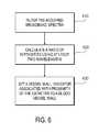
- FIG. 6shows another embodiment of a method for detecting blood-vessel wall artifacts due to catheter proximity to a vessel wall.
- broadband spectraare acquired and filtered to attenuate background and random noise.
- a variety of noise reduction filterscan be used depending on the particular application, including linear or non-linear filters.
- FIG. 7provides an example graph showing data before and after using a filter.
- a ratiois calculated using at least two wavelength intensities. As previously described, a narrow range can also be used around two wavelength intensities.
- a vessel wall indicatoris set based on the proximity of the catheter to the blood-vessel wall. Using predetermined intensity thresholds, various levels of signal quality can be output to a clinician or data file, as previously described. Additionally, catheter position can be estimated based on the intensities.
- FIG. 8shows a catheter 810 in dashed lines that has a tip 812 adjacent a blood-vessel wall 814 .
- Light 816 illuminated from a tip 812 of the catheteris reflected from the blood-vessel wall (as shown by arrows 818 ) creating unwanted artifacts that can significantly interfere with hemodynamic measurements.
- the spectral intensity of the light received through the catheterincreases across a variety of wavelengths, particularly in the range of 400 nm to 1000 nm or higher with the catheter placed adjacent the wall 814 .
- a threshold 830can be set such that if the spectral intensity exceeds the threshold, an indicator can be provided to a clinician so that the clinician has immediate feedback on catheter tip location and placement.
- the cliniciancan move the catheter to the position shown at 840 in solid lines where the light transmitted into the blood is less affected by artifacts due to the blood-vessel walls.
- Such immediate feedback to the clinicianensures a high-signal quality for accurate hemodynamic measurements.
- FIGS. 9 and 10show other structures that can be used to implement the methods described herein.
- multiple light sources 910such as multiple colored LEDs can be used to provide discrete wavelengths that can be time multiplexed by sequencer control logic 920 to individually turn on at different times.
- the discrete signalsare transmitted through an optical transmit fiber 930 located in a catheter 935 into the blood and reflected into a receive fiber 940 .
- the receive fiber 940transmits the discrete reflected signals to a single photodetector of a spectrometer 950 .
- Multiple photodetectorsmay be employed to measure the special effects of the signals.
- a controller 960is coupled to the photodetectors and is used to determine blood-vessel wall artifacts and/or catheter tip location, as previously described.
- single or multiple light sources 1010may be transmitted through a wavelength filter 1012 , such as a filter wheel, to provide an alternate or additional embodiment of discrete wavelengths that may be time multiplexed.
- the light signalsare passed through the filter 1012 and transmitted through an optical fiber 1020 located in a catheter 1025 into blood 1030 and then reflected back through a receive fiber 1040 to at least one photodetector 1050 .
- a controller 1060is coupled to the photodetectors and is used to determine blood-vessel wall artifacts and/or catheter tip location, as previously described.
- program modulesinclude routines, programs, libraries, objects, classes, components, data structures, etc., that perform particular tasks or implement particular abstract data types.
- the functionality of the program modulesmay be combined or split between program modules as desired in various embodiments.
- Computer-executable instructions for program modulesmay be executed within a local or distributed computing environment.
- Any of the disclosed methodscan be implemented as computer-executable instructions stored on one or more computer-readable storage media (e.g., non-transitory computer-readable media, such as one or more optical media discs, volatile memory components (such as DRAM or SRAM), or nonvolatile memory components (such as hard drives)) and executed on a computer (e.g., any commercially available computer, including smart phones or other mobile devices that include computing hardware).
- a computere.g., any commercially available computer, including smart phones or other mobile devices that include computing hardware.
- Any of the computer-executable instructions for implementing the disclosed techniques as well as any data created and used during implementation of the disclosed embodimentscan be stored on one or more computer-readable media (e.g., non-transitory computer-readable media).
- the computer-executable instructionscan be part of, for example, a dedicated software application or a software application that is accessed or downloaded via a web browser or other software application (such as a remote computing application).
- Such softwarecan be executed, for example, on a single local computer (e.g., any suitable commercially available computer) or in a network environment (e.g., via the Internet, a wide-area network, a local-area network, a client-server network (such as a cloud computing network), or other such network) using one or more network computers.
- any of the software-based embodimentscan be uploaded, downloaded, or remotely accessed through a suitable communication means.
- suitable communication meansinclude, for example, the Internet, the World Wide Web, an intranet, software applications, cable (including fiber optic cable), magnetic communications, electromagnetic communications (including RF, microwave, and infrared communications), electronic communications, or other such communication means.
Landscapes
- Health & Medical Sciences (AREA)
- Life Sciences & Earth Sciences (AREA)
- Engineering & Computer Science (AREA)
- General Health & Medical Sciences (AREA)
- Animal Behavior & Ethology (AREA)
- Biophysics (AREA)
- Biomedical Technology (AREA)
- Heart & Thoracic Surgery (AREA)
- Veterinary Medicine (AREA)
- Public Health (AREA)
- Molecular Biology (AREA)
- Surgery (AREA)
- Physics & Mathematics (AREA)
- Pathology (AREA)
- Medical Informatics (AREA)
- Signal Processing (AREA)
- Psychiatry (AREA)
- Computer Vision & Pattern Recognition (AREA)
- Physiology (AREA)
- Artificial Intelligence (AREA)
- Pulmonology (AREA)
- Anesthesiology (AREA)
- Hematology (AREA)
- Measurement Of The Respiration, Hearing Ability, Form, And Blood Characteristics Of Living Organisms (AREA)
- Investigating Or Analysing Materials By Optical Means (AREA)
- Endoscopes (AREA)
- Media Introduction/Drainage Providing Device (AREA)
Abstract
Description
Claims (17)
Priority Applications (1)
| Application Number | Priority Date | Filing Date | Title |
|---|---|---|---|
| US13/878,411US9492090B2 (en) | 2010-10-08 | 2011-10-05 | Detection of blood-vessel wall artifacts |
Applications Claiming Priority (3)
| Application Number | Priority Date | Filing Date | Title |
|---|---|---|---|
| US39143010P | 2010-10-08 | 2010-10-08 | |
| US13/878,411US9492090B2 (en) | 2010-10-08 | 2011-10-05 | Detection of blood-vessel wall artifacts |
| PCT/US2011/054871WO2012047965A1 (en) | 2010-10-08 | 2011-10-05 | Detection of blood-vessel wall artifacts |
Publications (2)
| Publication Number | Publication Date |
|---|---|
| US20130324840A1 US20130324840A1 (en) | 2013-12-05 |
| US9492090B2true US9492090B2 (en) | 2016-11-15 |
Family
ID=44802416
Family Applications (1)
| Application Number | Title | Priority Date | Filing Date |
|---|---|---|---|
| US13/878,411Active2033-05-07US9492090B2 (en) | 2010-10-08 | 2011-10-05 | Detection of blood-vessel wall artifacts |
Country Status (5)
| Country | Link |
|---|---|
| US (1) | US9492090B2 (en) |
| EP (1) | EP2624755B1 (en) |
| JP (1) | JP5964838B2 (en) |
| CN (1) | CN103237496B (en) |
| WO (1) | WO2012047965A1 (en) |
Families Citing this family (31)
| Publication number | Priority date | Publication date | Assignee | Title |
|---|---|---|---|---|
| EP3606592B1 (en) | 2017-04-07 | 2025-01-08 | Bard Access Systems, Inc. | Optical fiber-based medical device tracking and monitoring system |
| EP4013338A4 (en) | 2019-08-12 | 2023-08-30 | Bard Access Systems, Inc. | SHAPE DETECTION SYSTEMS AND METHODS FOR MEDICAL DEVICES |
| CN112826497B (en)* | 2019-11-25 | 2025-09-09 | 巴德阿克塞斯系统股份有限公司 | Optical tip tracking system and method thereof |
| EP4061272A4 (en) | 2019-11-25 | 2023-11-22 | Bard Access Systems, Inc. | Shape-sensing systems with filters and methods thereof |
| CN215461207U (en) | 2020-02-28 | 2022-01-11 | 巴德阿克塞斯系统股份有限公司 | Catheter and medical instrument monitoring system |
| US11474310B2 (en) | 2020-02-28 | 2022-10-18 | Bard Access Systems, Inc. | Optical connection systems and methods thereof |
| CN113332561A (en) | 2020-03-03 | 2021-09-03 | 巴德阿克塞斯系统股份有限公司 | System and method for optical shape sensing and electrical signal conduction |
| WO2021202589A1 (en) | 2020-03-30 | 2021-10-07 | Bard Access Systems, Inc. | Optical and electrical diagnostic systems and methods thereof |
| CN113842536A (en) | 2020-06-26 | 2021-12-28 | 巴德阿克塞斯系统股份有限公司 | Dislocation detection system |
| WO2022005870A1 (en) | 2020-06-29 | 2022-01-06 | Bard Access Systems, Inc. | Automatic dimensional frame reference for fiber optic |
| WO2022011287A1 (en) | 2020-07-10 | 2022-01-13 | Bard Access Systems, Inc. | Continuous fiber optic functionality monitoring and self-diagnostic reporting system |
| US11877810B2 (en) | 2020-07-21 | 2024-01-23 | Bard Access Systems, Inc. | System, method and apparatus for magnetic tracking of ultrasound probe and generation of 3D visualization thereof |
| WO2022031613A1 (en) | 2020-08-03 | 2022-02-10 | Bard Access Systems, Inc. | Bragg grated fiber optic fluctuation sensing and monitoring system |
| EP4185209A1 (en)* | 2020-08-04 | 2023-05-31 | Bard Access Systems, Inc. | System and method for optimized medical component insertion monitoring and imaging enhancement |
| WO2022035760A1 (en) | 2020-08-10 | 2022-02-17 | Bard Access Systems, Inc. | System and method for generating vessel representations in mixed reality/virtual reality |
| CN114246583A (en) | 2020-09-25 | 2022-03-29 | 巴德阿克塞斯系统股份有限公司 | Fiber Optic Oximetry Systems for Detection and Confirmation |
| WO2022072727A2 (en) | 2020-10-02 | 2022-04-07 | Bard Access Systems, Inc. | Ultrasound systems and methods for sustained spatial attention |
| CN114344514A (en) | 2020-10-13 | 2022-04-15 | 巴德阿克塞斯系统股份有限公司 | Disinfection enclosure for fiber optic connectors and method thereof |
| EP4228516A1 (en) | 2020-10-15 | 2023-08-23 | Bard Access Systems, Inc. | Ultrasound imaging system for generation of a three-dimensional ultrasound image |
| CN114518075A (en) | 2020-11-18 | 2022-05-20 | 巴德阿克塞斯系统股份有限公司 | fiber optic stylet holder |
| WO2022115624A1 (en) | 2020-11-24 | 2022-06-02 | Bard Access Systems, Inc. | Steerable fiber optic shape sensing enabled elongated medical instrument |
| WO2022150411A1 (en) | 2021-01-06 | 2022-07-14 | Bard Access Systems, Inc. | Needle guidance using fiber optic shape sensing |
| US12426954B2 (en) | 2021-01-26 | 2025-09-30 | Bard Access Systems, Inc. | Fiber optic shape sensing system associated with port placement |
| US12419694B2 (en) | 2021-10-25 | 2025-09-23 | Bard Access Systems, Inc. | Reference plane for medical device placement |
| US12318149B2 (en) | 2022-03-08 | 2025-06-03 | Bard Access Systems, Inc. | Medical shape sensing devices and systems |
| US12426956B2 (en) | 2022-03-16 | 2025-09-30 | Bard Access Systems, Inc. | Medical system and method for monitoring medical device insertion and illumination patterns |
| US12089815B2 (en) | 2022-03-17 | 2024-09-17 | Bard Access Systems, Inc. | Fiber optic medical systems and devices with atraumatic tip |
| US12102481B2 (en) | 2022-06-03 | 2024-10-01 | Bard Access Systems, Inc. | Ultrasound probe with smart accessory |
| US12343117B2 (en) | 2022-06-28 | 2025-07-01 | Bard Access Systems, Inc. | Fiber optic medical systems and methods for identifying blood vessels |
| US12349984B2 (en) | 2022-06-29 | 2025-07-08 | Bard Access Systems, Inc. | System, method, and apparatus for improved confirm of an anatomical position of a medical instrument |
| US12137989B2 (en) | 2022-07-08 | 2024-11-12 | Bard Access Systems, Inc. | Systems and methods for intelligent ultrasound probe guidance |
Citations (18)
| Publication number | Priority date | Publication date | Assignee | Title |
|---|---|---|---|---|
| US4523279A (en) | 1980-11-24 | 1985-06-11 | Oximetrix, Inc. | Apparatus for determining oxygen saturation levels in blood |
| US5647359A (en) | 1993-04-01 | 1997-07-15 | Terumo Kabushiki Kaisha | Measuring apparatus |
| US5678550A (en)* | 1995-08-11 | 1997-10-21 | The United States Of America As Represented By The Secretary Of The Department Of Health And Human Services | Apparatus and method for in situ detection of areas of cardiac electrical activity |
| US5758644A (en)* | 1995-06-07 | 1998-06-02 | Masimo Corporation | Manual and automatic probe calibration |
| US5995208A (en) | 1998-05-28 | 1999-11-30 | Abbott Laboratories | Intravascular oximetry catheter |
| US6096065A (en)* | 1997-09-29 | 2000-08-01 | Boston Scientific Corporation | Sheath for tissue spectroscopy |
| US20040077950A1 (en)* | 2002-08-05 | 2004-04-22 | Marshik-Geurts Barbara J. | Near-infrared spectroscopic analysis of blood vessel walls |
| US20060041199A1 (en)* | 2004-06-18 | 2006-02-23 | Elmaleh David R | Intravascular imaging device and uses thereof |
| US7233817B2 (en) | 2002-11-01 | 2007-06-19 | Brian Yen | Apparatus and method for pattern delivery of radiation and biological characteristic analysis |
| WO2009079626A1 (en) | 2007-12-19 | 2009-06-25 | St. Jude Medical, Atrial Fibrillation Division, Inc. | Photodynamic-based tissue sensing device and method |
| US7580185B2 (en)* | 2002-08-28 | 2009-08-25 | Carl Zeiss Surgical Gmbh | Microscopy system, microscopy method and a method of treating an aneurysm |
| US20090253989A1 (en)* | 2008-04-03 | 2009-10-08 | Infraredx, Inc. | System and Method for Intravascular Structural Analysis Compensation of Chemical Analysis Modality |
| US20100069760A1 (en)* | 2008-09-17 | 2010-03-18 | Cornova, Inc. | Methods and apparatus for analyzing and locally treating a body lumen |
| US8167794B2 (en)* | 2003-06-17 | 2012-05-01 | Olympus Corporation | Endoscope system for fluorescent observation |
| US8401619B2 (en)* | 2009-09-22 | 2013-03-19 | Visen Medical, Inc. | Systems and methods for virtual index-matching of diffusive media |
| US8406840B2 (en) | 2005-09-13 | 2013-03-26 | Koninklijke Philips Electronics N.V. | Spatially resolved oxymetry |
| US20140005553A1 (en)* | 2010-09-21 | 2014-01-02 | Cornova, Inc. | Systems and methods for analysis and treatment of a body lumen |
| US8870740B2 (en)* | 2008-12-30 | 2014-10-28 | Koninklijke Philips N.V. | System and method for providing light therapy to a subject |
Family Cites Families (1)
| Publication number | Priority date | Publication date | Assignee | Title |
|---|---|---|---|---|
| JPH06319724A (en)* | 1993-05-17 | 1994-11-22 | Terumo Corp | Measuring device |
- 2011
- 2011-10-05CNCN201180058538.2Apatent/CN103237496B/enactiveActive
- 2011-10-05WOPCT/US2011/054871patent/WO2012047965A1/enactiveApplication Filing
- 2011-10-05USUS13/878,411patent/US9492090B2/enactiveActive
- 2011-10-05JPJP2013532903Apatent/JP5964838B2/enactiveActive
- 2011-10-05EPEP11770629.1Apatent/EP2624755B1/enactiveActive
Patent Citations (18)
| Publication number | Priority date | Publication date | Assignee | Title |
|---|---|---|---|---|
| US4523279A (en) | 1980-11-24 | 1985-06-11 | Oximetrix, Inc. | Apparatus for determining oxygen saturation levels in blood |
| US5647359A (en) | 1993-04-01 | 1997-07-15 | Terumo Kabushiki Kaisha | Measuring apparatus |
| US5758644A (en)* | 1995-06-07 | 1998-06-02 | Masimo Corporation | Manual and automatic probe calibration |
| US5678550A (en)* | 1995-08-11 | 1997-10-21 | The United States Of America As Represented By The Secretary Of The Department Of Health And Human Services | Apparatus and method for in situ detection of areas of cardiac electrical activity |
| US6096065A (en)* | 1997-09-29 | 2000-08-01 | Boston Scientific Corporation | Sheath for tissue spectroscopy |
| US5995208A (en) | 1998-05-28 | 1999-11-30 | Abbott Laboratories | Intravascular oximetry catheter |
| US20040077950A1 (en)* | 2002-08-05 | 2004-04-22 | Marshik-Geurts Barbara J. | Near-infrared spectroscopic analysis of blood vessel walls |
| US7580185B2 (en)* | 2002-08-28 | 2009-08-25 | Carl Zeiss Surgical Gmbh | Microscopy system, microscopy method and a method of treating an aneurysm |
| US7233817B2 (en) | 2002-11-01 | 2007-06-19 | Brian Yen | Apparatus and method for pattern delivery of radiation and biological characteristic analysis |
| US8167794B2 (en)* | 2003-06-17 | 2012-05-01 | Olympus Corporation | Endoscope system for fluorescent observation |
| US20060041199A1 (en)* | 2004-06-18 | 2006-02-23 | Elmaleh David R | Intravascular imaging device and uses thereof |
| US8406840B2 (en) | 2005-09-13 | 2013-03-26 | Koninklijke Philips Electronics N.V. | Spatially resolved oxymetry |
| WO2009079626A1 (en) | 2007-12-19 | 2009-06-25 | St. Jude Medical, Atrial Fibrillation Division, Inc. | Photodynamic-based tissue sensing device and method |
| US20090253989A1 (en)* | 2008-04-03 | 2009-10-08 | Infraredx, Inc. | System and Method for Intravascular Structural Analysis Compensation of Chemical Analysis Modality |
| US20100069760A1 (en)* | 2008-09-17 | 2010-03-18 | Cornova, Inc. | Methods and apparatus for analyzing and locally treating a body lumen |
| US8870740B2 (en)* | 2008-12-30 | 2014-10-28 | Koninklijke Philips N.V. | System and method for providing light therapy to a subject |
| US8401619B2 (en)* | 2009-09-22 | 2013-03-19 | Visen Medical, Inc. | Systems and methods for virtual index-matching of diffusive media |
| US20140005553A1 (en)* | 2010-09-21 | 2014-01-02 | Cornova, Inc. | Systems and methods for analysis and treatment of a body lumen |
Non-Patent Citations (5)
| Title |
|---|
| Chinese Office Action, Jul. 2, 2013. |
| European Office Action, May 8, 2014. |
| European Office Action, Nov. 7, 2014. |
| International Search Report, PCT/US2011/054871, Jan. 13, 2012. |
| Office Action issued in JP Application No. 2013-532903, Sep. 18, 2015. |
Also Published As
| Publication number | Publication date |
|---|---|
| JP5964838B2 (en) | 2016-08-03 |
| CN103237496A (en) | 2013-08-07 |
| JP2014501541A (en) | 2014-01-23 |
| EP2624755A1 (en) | 2013-08-14 |
| EP2624755B1 (en) | 2020-01-22 |
| CN103237496B (en) | 2016-02-24 |
| WO2012047965A1 (en) | 2012-04-12 |
| WO2012047965A8 (en) | 2013-05-10 |
| US20130324840A1 (en) | 2013-12-05 |
Similar Documents
| Publication | Publication Date | Title |
|---|---|---|
| US9492090B2 (en) | Detection of blood-vessel wall artifacts | |
| US20130324815A1 (en) | Continuous measurement of total hemoglobin | |
| CN107666860B (en) | Photoplethysmography device | |
| US20120165629A1 (en) | Systems and methods of monitoring a patient through frequency-domain photo migration spectroscopy | |
| JP5432253B2 (en) | System and method for processing signals with repetitive features | |
| US20220369942A1 (en) | Light-based non-invasive blood pressure systems and methods | |
| US8221326B2 (en) | Detection of oximetry sensor sites based on waveform characteristics | |
| US20120310062A1 (en) | Photon density wave based determination of physiological blood parameters | |
| US8571623B2 (en) | System and method for detection of venous pulsation | |
| US10117590B2 (en) | Transcutaneous measurement of hemoglobin changes to calculate estimated blood volume change during peritoneal dialysis | |
| JP5527658B2 (en) | Scattering absorber measurement method and apparatus | |
| US8483788B2 (en) | Motion compensation in a sensor | |
| CN104394766A (en) | Real-time tumor perfusion imaging during radiation therapy delivery | |
| WO2011014297A1 (en) | Patient monitoring system and method utilising photon density waves in transmission mode | |
| US20150190208A1 (en) | System and method for user interaction with medical equipment | |
| CN112137624A (en) | Method for measuring blood oxygen saturation | |
| JPH0961343A (en) | Optical measuring method and optical measuring device | |
| US10098575B2 (en) | Methods and systems for determining physiological information based on distortion information | |
| US20140275870A1 (en) | Continuous noninvasive measurement of analyte concentration using an optical bridge | |
| US20140275882A1 (en) | Methods and Systems for Determining a Probe-Off Condition in a Medical Device | |
| US20140187884A1 (en) | Systems and methods for ensemble averaging in pulse oximetry | |
| JP6537900B2 (en) | Medical device, biological parameter analysis method and biological parameter analysis program | |
| EP2339957A1 (en) | Method and system for non-invasively monitoring fluid flow in a subject | |
| US8712492B2 (en) | Photon density wave based determination of physiological blood parameters | |
| AU2021107062A4 (en) | Hemoglobin and Melanin Based Pulse Oximetry |
Legal Events
| Date | Code | Title | Description |
|---|---|---|---|
| AS | Assignment | Owner name:EDWARDS LIFESCIENCES CORPORATION, CALIFORNIA Free format text:ASSIGNMENT OF ASSIGNORS INTEREST;ASSIGNORS:JIAN, ZHONGPIN;YOUNG, CLAYTON;HATIB, FERAS;SIGNING DATES FROM 20110725 TO 20110801;REEL/FRAME:030181/0327 | |
| AS | Assignment | Owner name:EDWARDS LIFESCIENCES CORPORATION, CALIFORNIA Free format text:CORRECTIVE ASSIGNMENT TO CORRECT THE SPELLING OF ZHONGPING JIAN'S FIRST NAME. THE "G" IS MISSING FROM THE PREVIOUS ASSIGNMENT PREVIOUSLY RECORDED ON REEL 030181 FRAME 0327. ASSIGNOR(S) HEREBY CONFIRMS THE ASSIGNMENT FROM JIAN ET AL. TO EDWARDS LIFESCIENCES CORPORATION;ASSIGNOR:JIAN, ZHONGPING;REEL/FRAME:030293/0080 Effective date:20130424 | |
| STCF | Information on status: patent grant | Free format text:PATENTED CASE | |
| MAFP | Maintenance fee payment | Free format text:PAYMENT OF MAINTENANCE FEE, 4TH YEAR, LARGE ENTITY (ORIGINAL EVENT CODE: M1551); ENTITY STATUS OF PATENT OWNER: LARGE ENTITY Year of fee payment:4 | |
| MAFP | Maintenance fee payment | Free format text:PAYMENT OF MAINTENANCE FEE, 8TH YEAR, LARGE ENTITY (ORIGINAL EVENT CODE: M1552); ENTITY STATUS OF PATENT OWNER: LARGE ENTITY Year of fee payment:8 | |
| AS | Assignment | Owner name:BD SWITZERLAND SARL, SWITZERLAND Free format text:ASSIGNMENT OF ASSIGNORS INTEREST;ASSIGNORS:EDWARDS LIFESCIENCES CORPORATION;EDWARDS LIFESCIENCES LLC;EDWARDS LIFESCIENCES SARL;AND OTHERS;REEL/FRAME:070634/0001 Effective date:20240903 Owner name:BECTON, DICKINSON AND COMPANY, NEW JERSEY Free format text:ASSIGNMENT OF ASSIGNORS INTEREST;ASSIGNOR:BD SWITZERLAND SARL;REEL/FRAME:070179/0813 Effective date:20241021 |