US9491007B2 - Apparatus and method for antenna matching - Google Patents
Apparatus and method for antenna matchingDownload PDFInfo
- Publication number
- US9491007B2 US9491007B2US14/280,775US201414280775AUS9491007B2US 9491007 B2US9491007 B2US 9491007B2US 201414280775 AUS201414280775 AUS 201414280775AUS 9491007 B2US9491007 B2US 9491007B2
- Authority
- US
- United States
- Prior art keywords
- cable
- antenna
- matching circuit
- impedance
- tunable matching
- Prior art date
- Legal status (The legal status is an assumption and is not a legal conclusion. Google has not performed a legal analysis and makes no representation as to the accuracy of the status listed.)
- Active
Links
Images


Classifications
- H—ELECTRICITY
- H04—ELECTRIC COMMUNICATION TECHNIQUE
- H04L—TRANSMISSION OF DIGITAL INFORMATION, e.g. TELEGRAPHIC COMMUNICATION
- H04L25/00—Baseband systems
- H04L25/02—Details ; arrangements for supplying electrical power along data transmission lines
- H04L25/0264—Arrangements for coupling to transmission lines
- H04L25/0278—Arrangements for impedance matching
- H—ELECTRICITY
- H01—ELECTRIC ELEMENTS
- H01Q—ANTENNAS, i.e. RADIO AERIALS
- H01Q1/00—Details of, or arrangements associated with, antennas
- H01Q1/12—Supports; Mounting means
- H01Q1/22—Supports; Mounting means by structural association with other equipment or articles
- H01Q1/24—Supports; Mounting means by structural association with other equipment or articles with receiving set
- H01Q1/241—Supports; Mounting means by structural association with other equipment or articles with receiving set used in mobile communications, e.g. GSM
- H01Q1/242—Supports; Mounting means by structural association with other equipment or articles with receiving set used in mobile communications, e.g. GSM specially adapted for hand-held use
- H—ELECTRICITY
- H01—ELECTRIC ELEMENTS
- H01Q—ANTENNAS, i.e. RADIO AERIALS
- H01Q1/00—Details of, or arrangements associated with, antennas
- H01Q1/50—Structural association of antennas with earthing switches, lead-in devices or lightning protectors
- H—ELECTRICITY
- H01—ELECTRIC ELEMENTS
- H01Q—ANTENNAS, i.e. RADIO AERIALS
- H01Q1/00—Details of, or arrangements associated with, antennas
- H01Q1/52—Means for reducing coupling between antennas; Means for reducing coupling between an antenna and another structure
- H—ELECTRICITY
- H01—ELECTRIC ELEMENTS
- H01Q—ANTENNAS, i.e. RADIO AERIALS
- H01Q21/00—Antenna arrays or systems
- H01Q21/28—Combinations of substantially independent non-interacting antenna units or systems
- H—ELECTRICITY
- H03—ELECTRONIC CIRCUITRY
- H03H—IMPEDANCE NETWORKS, e.g. RESONANT CIRCUITS; RESONATORS
- H03H7/00—Multiple-port networks comprising only passive electrical elements as network components
- H03H7/38—Impedance-matching networks
- H03H7/40—Automatic matching of load impedance to source impedance
- H—ELECTRICITY
- H04—ELECTRIC COMMUNICATION TECHNIQUE
- H04B—TRANSMISSION
- H04B1/00—Details of transmission systems, not covered by a single one of groups H04B3/00 - H04B13/00; Details of transmission systems not characterised by the medium used for transmission
- H04B1/02—Transmitters
- H04B1/04—Circuits
- H04B1/0458—Arrangements for matching and coupling between power amplifier and antenna or between amplifying stages
- H—ELECTRICITY
- H04—ELECTRIC COMMUNICATION TECHNIQUE
- H04B—TRANSMISSION
- H04B1/00—Details of transmission systems, not covered by a single one of groups H04B3/00 - H04B13/00; Details of transmission systems not characterised by the medium used for transmission
- H04B1/06—Receivers
- H04B1/16—Circuits
- H04B1/18—Input circuits, e.g. for coupling to an antenna or a transmission line
- H—ELECTRICITY
- H04—ELECTRIC COMMUNICATION TECHNIQUE
- H04B—TRANSMISSION
- H04B3/00—Line transmission systems
- H04B3/02—Details
- H04B3/03—Hybrid circuits
- H—ELECTRICITY
- H04—ELECTRIC COMMUNICATION TECHNIQUE
- H04M—TELEPHONIC COMMUNICATION
- H04M1/00—Substation equipment, e.g. for use by subscribers
- H04M1/02—Constructional features of telephone sets
- H04M1/0202—Portable telephone sets, e.g. cordless phones, mobile phones or bar type handsets
- H04M1/026—Details of the structure or mounting of specific components
- H04M1/0274—Details of the structure or mounting of specific components for an electrical connector module
- H—ELECTRICITY
- H04—ELECTRIC COMMUNICATION TECHNIQUE
- H04M—TELEPHONIC COMMUNICATION
- H04M2250/00—Details of telephonic subscriber devices
- H04M2250/12—Details of telephonic subscriber devices including a sensor for measuring a physical value, e.g. temperature or motion
Definitions
- the present inventionrelates generally to radio communication devices, and more specifically to antenna systems used in handheld radio communication devices.
- Radio communication devicestypically employ antennas that optimize radio signal transmission and reception.
- the antennasare often coupled to the transmitter output signal and/or the receiver input signal connector though impedance matching circuits so that the transmitters and receivers can be designed and tested to a specified value.
- the impedance matching circuitscan then be designed or adjusted for differing antennas or differing antenna environments, which vary the impedances of the antennas that may be coupled to the transmitters and/or receivers.
- Antenna matching circuitsmay have different impedance matching states that are selectable according to a radio channel and environmental conditions. In the case of handheld electronic devices, such environmental conditions include the presence of a user's hands in a variety of positions relative to an antenna or an antenna element.
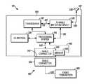
- FIG. 1is an electrical block diagram that shows a radio communication device and a cable, in accordance with certain embodiments.
- FIG. 2is a three dimensional drawing that shows some parts of the antenna described with reference to FIG. 1 , in accordance with certain embodiments.
- FIGS. 3-5are three dimensional drawings, each showing a cable connector described with reference to FIG. 1 an antenna element, in accordance with certain embodiments.
- FIG. 6is a graph that shows plots of antenna return loss for a particular radio communication device in the presence and absence of a particular cable.
- FIG. 7is a graph that shows plots of radiation efficiencies and system efficiencies for different situations of the cellular telephone and the presence and absence of a USB cable, in accordance with certain embodiments.
- FIG. 8is a flow chart that shows some steps of a method for tuning a tunable matching circuit, in accordance with certain embodiments.
- Embodiments described hereingenerally relate to radio communication devices that are designed with an antenna that has an element through which a cable connection is formed.
- a radio communication deviceis a cellular telephone.
- an antenna elementis an antenna element that is positioned on the narrow dimension of the radio communication device—i.e., around part of the edge of a thin rectangular shaped radio communication device.
- the radio communication device 101may be any radio communication device having at least one antenna element near to or through which a cable is connected to the radio communication device 101 .
- Embodiments in which the antenna element has been modified to allow passage of the cable connector by removing more of the conductive material of the elementtypically provide more improvement. Some benefits may still be obtained for situations in which the cable connector is proximate the antenna element, and for which there is no reduction of the antenna element material proximate the cable connector. These relationships will be described in more detail with reference to FIGS. 3-5 .
- the radio communication device 101comprises a housing 105 , a transceiver 110 , a processing system 115 , an antenna 120 , a tunable matching circuit 125 , an input/output section 130 , a cable connector 140 , and a sensor 145 .
- the radio communication device 101may be, for example, a cellular telephone, an electronic tablet, an electronic pad, a monitoring device, a vehicular communication device, just to name a few.
- the cable 150comprises a compatible cable connector 155 designed to mate with cable connector 140 , a cable that is designed to include wires that carry electrical signals that may be DC or AC.
- the AC signalsmay include analog or digital signals, and may include audio, video, and/or radio frequency bandwidths. Certain wires may be shielded.
- the cable 156is terminated in a cable termination 160 that may be another cable connector or an electronic device.
- the transceiver 110is a radio transceiver 110 .
- the transceiver 110may be one of one or more transceivers in the radio communication device 101 .
- the radio communication device 101may have a cellular transceiver and a Wi-Fi hotspot transceiver.
- the transceiver 110represents any one transceiver when there are multiple transceivers in the radio communication device 101 .
- the transceiver 110may provide transmitting and receiving functions (e.g., a cellular system transmitter-receiver), or a transmitting only function (e.g., a sign-post transmitter), or a receiving only function (e.g., a global positioning system (GPS) receiver).
- the transceiver 110may comprise one or more processors and associated memories for controlling the operation of the transceiver 110 .
- the transceiver 110is coupled to the antenna 120 .
- the manner in which the antenna 120 is drawnis intended to indicate that it may comprise one or more antenna elements that are outside of the housing 105 , or on the housing 105 , or within the housing 105 , as well as an antenna signal 126 that couples the antenna elements to the tunable matching circuit 125 .
- the antenna 120is illustrated to show one particular antenna element 121 that is a conductive material, such as a metal alloy, disposed on the surface of the housing 105 . It may be disposed by plating techniques or mechanical attachment techniques.
- the cable connector 140 of the radio communication device 101has a connector insertion cavity with a face 141 that is approximately flush with the surface of the housing 105 and the antenna element 121 .
- the cable connector 140either protrudes from or is recessed from the surface of the antenna element 121 .
- the cable connector 140may be printed circuit board mounted and/or may have a flange, resulting in a disposition of the face 141 such that it is recessed from or protrudes from the antenna element 121 by a distance that is small in comparison to the size of the antenna element 121 .
- the illustration of the antenna element 121indicates that it is disposed on three sides of the housing 105 , the antenna element 121 need not be so disposed. That is, the antenna element 121 may alternatively be disposed along only part of one side of the housing and may be plated on either the inner or outer surface of the housing 105 .
- the antenna element 121may be implemented as an independent structure that is located with reference to the radio communication device 101 and the cable connector 140 such that the antenna element 121 has a hole or cutout where the cable connector 140 passes through the antenna element 121 .
- the antenna element 121may be a bent or flat punched metal piece that is mounted to a printed circuit board inside the housing 105 of the radio communication device 101 .
- the tunable matching circuit 125is coupled to the transceiver 110 .
- the tunable matching circuit 125is coupled to a RF output port and an RF input port of the transceiver 110 , which may be a common RF port 111 .
- the tunable matching circuit 125is coupled to the RF port 111 that is one of an RF output port or RF input port of the transceiver 110 .
- the RF transmitter of the transceiver 110is designed to generate an RF signal at a selected power at a designed output impedance of the RF transmitter.
- the signalis coupled through the tunable matching circuit 125 to the antenna 120 .
- the RF receiver of the transceiver 110is designed to receive an RF signal within a designated power range at a designed input impedance of the RF receiver, wherein the RF signal is coupled from antenna 120 through the tunable matching circuit 125 to the RF input port 111 .
- the tunable matching circuit 125is also coupled to the processing system 115 .
- the tunable matching circuit 125is a circuit that provides a selected impedance transform, or matching state, selected by control signals 116 from the processing system 115 .
- the processing system 115is also coupled to the sensor 145 .
- the processing systemgenerates the control signals 116 in response to a cable detection signal 146 generated by the sensor 145 and other parameters, such as the selected radio channel and an environmental state of the radio communication device 101 .
- Each particular impedance transform that is selected by the control signals 116is designed to match the impedance of the antenna 120 to the impedance of the RF port or ports 111 .
- the impedance of the antennamay change for different states of the transceiver 110 , the environment of the radio communication device 101 , and the cable connection state signal. Selecting an impedance transform optimizes the transfer of signal power between the transceiver 110 and the antenna 120 .
- the states, the environment, and the cable connection stateare indicated by the control signals 116 .
- the selected impedance transformsare mapped to the control signals 116 , for example by a table stored in a memory.
- the action of selecting an impedance transform or matching state using the mapping functionis called tuning the tunable matching circuit 125 .
- Each impedance transformmay comprise stages of passive impedance devices, each stage able to be set to one of a plurality of gains and/or phases primarily within a narrow frequency band.
- the narrow frequency bands of the setsare combined to provide an impedance transform over a wide frequency band.
- the selectionmay involve the use of transistor switches.
- the selected impedance transformmay provide an impedance at the antenna coupling which is the complex conjugate of the antenna impedance, and an impedance at the transceiver coupling which is the complex conjugate of the designed transceiver impedance, thereby maximizing the transfer of signal power between the transceiver and the antenna.
- Other known methods of providing a set of impedance transforms in a tunable matching circuitmay alternatively be used.
- one or more aspect of communication device 101 performancemay be improved, such as transmitter radiated power, receiver sensitivity, communication range or distance, data rate, error rate, or energy efficiency.
- Transceiver 110is also coupled to the processing system 115 .
- the processing system 115is coupled to an input/output section 130 , which includes human interface functions such as indicators, buttons, a graphical display, touch screen sensors as well as other sensor, such as position, orientation, and acceleration.
- the processing system 115may be coupled to one or more other transceivers (not shown in FIG. 1 ) of the radio communication device 101 and other circuits (not shown in FIG. 1 ), of which just one example is a battery control circuits.
- There are alternative embodiments of the radio communication device 101that relate to the configuration of the processing system 115 and the transceiver 110 and provide the same benefits. In the embodiments shown in FIG.
- the control signals 116 that indicate the states, environment, and cable connection stateare generated by processing system 115 .
- the processing system 115may be controlling the channel selection and other parameters (e.g., power output) of the transceiver 110 and the processing system 115 may also determine the environment of the radio communication device 101 . Examples of the environment of the radio communication device 101 are a user's head proximity to the radio communication device 101 and a location of a user's hand holding the radio communication device 101 .
- the control signals 116may originate in the processing system 115 .
- the transceiver 110may have its own processing system that controls the channel selection and other parameters of the transceiver, largely based on channel control messages that are exchanged between a processing system 115 of the transceiver 110 and a fixed network radio station. These signals may be passed to the processing system 115 , which generates control signals 116 from them and the cable detection signal 146 .
- the transceiver 110has its own processing system and the signals that indicate the channel selection and other parameters of the transceiver 110 are coupled directly to the tunable matching circuit by signals 112 , while the processing system 115 couples the cable connection state to the tunable matching circuit in the control signals 116 .
- the determination of the environment of the radio communication device 101may be determined either by the processing system 115 or the processing system of the transceiver.
- the mapping of the states, the environment, and the cable connection state to a particular impedance transformmay be a memory based mapping function performed in the tunable matching circuit 125 .
- Other configurationsmay provide the same benefits.
- the mapping functioncould be done in the transceiver 110 , and the transceiver 110 would then directly control the switching of the impedance stages of the tunable matching circuit 125 .
- the cable connection statemay be coupled to the transceiver 110 either directly from the sensor 145 or through the processing system 115 .
- the cable connection statemay be coupled by cable detection signal 146 directly to a control circuit of the tunable matching circuit 125 .
- the control circuitmay be the mapping function.
- the processing system 115may be referred to as a control circuit.
- the processing system 115is also coupled to the cable connector 140 .
- cable signals 142may be passed between the processing system 115 and the termination of the cable 160 .
- the sensor 145changes a cable connection state that in some embodiments is coupled by cable detection signal 146 to the processing system 115 .
- the cable connection statein this case changes from a cable absent state to a cable present state.
- the sensor 145may comprise an electrical contact moved by the insertion or extraction of the compatible cable connector 155 , a pull up resistor coupled to a DC voltage, and a ground, arranged in a manner known in the art.
- This type of sensormay be characterized as a contact switch, reflecting the fact that a moving contact is used with electronic parts and two voltage sources to cause two voltage states. Other types of switches could be used.
- a magnetic sensorknown as a Hall effect sensor.
- Another exampleis an optical detector.
- the cable 150may be, for example, a universal serial bus (USB) cable having a micro USB cable connector 155 .
- USBuniversal serial bus
- the cable connection stateis generated in response to a detection of one or more signals of the cable signals 142 .
- the detectionmay be performed by the processing system 115 .
- the sensor 145in this case is a combination of input/output circuits of the processing system 115 that are connected to the cable signals 142 , and additional logic circuits and/or execution of input/output driver instructions by the processing system 115 .
- the cable connection statemay be generated by the processing system 115 in response to a sensing that +5V has occurred on a +5V circuit line in the cable signals 142 .
- the presence of the compatible cable connector 155 and the wires in the cable 150 and other metallic parts of the compatible cable connectormay significantly degrade the efficiency of signal coupling between the antenna element 121 and the transceiver 110 from that which existed when the compatible cable connector 155 is not present.
- the cable connection state that indicates that the compatible cable connector 155 is presentmodifies the tunable matching circuit 125 to optimize the energy coupled between the antenna 120 and the transceiver 115 .
- the transfer function that results from the modificationwill typically be different depending on the state of the transceiver, and therefore the transfer function, that exists when the compatible cable connector is inserted into the cable connector 140 , which is determined by the control signals 116 .
- An example of the improvement achieved by this modificationis provided with reference to FIG. 7 .
- a three dimensional drawing 200shows some parts of the antenna 120 described with reference to FIG. 1 , disposed on a housing for a radio communication device such as radio communication device 101 , in accordance with certain embodiments.
- the antenna 120comprises a sectioned metal band 202 about a perimeter edge of the housing 105 of radio communication device 101 .
- the inner contents of the radio communication device 101are not specifically shown for clarity.
- the sectioned metal band 202may have multiple antenna elements. In this example there are a top antenna element 206 and a bottom antenna element 204 .
- first, second, third and fourth corner sectionsare provided to reduce the capacitive coupling between the antenna elements 204 , 206 and the electrical ground sections 208 , 210 by providing distance between the antenna elements 204 , 206 and ground.
- the reduction of coupling (i.e., decoupling) between the antenna elements 204 , 206 and the grounded sections 208 , 210improves the antenna efficiency.
- the four metal sections ( 212 , 214 , 216 , and 218 )may be referred to as parasitic sections, electrically floating sections and/or floating sections.
- the four metal sections( 212 , 214 , 216 , 218 ) are each positioned on the sectioned metal band 202 between an antenna section and a ground section.
- the number of floating segmentscan be reduced from four to two by eliminating the gaps 234 , 226 , 232 , 224 .
- the sectioned metal band 202comprises insulative or high impedance gaps between the various metal sections of the sectioned metal band 202 .
- the bottom antenna element 204is defined between a first gap 220 and a second gap 222 .
- the first corner section 212is adjacent to and separated from a first side of the bottom antenna element 204 by the first gap 220 .
- the first grounded section 208is adjacent to and separated from the first corner section 212 by a third gap 224 .
- the second corner section 214is adjacent to and separated from a second side of the top antenna 204 by the second gap 222 .
- the second grounded section 210is adjacent to and separated from the second corner section 214 by a fourth gap 226 .
- the top antenna element 206is positioned between a fifth gap 228 and a sixth gap 230 .
- the third corner section 216is adjacent to and separated from a first side of the top antenna element 206 by the fifth gap 228 .
- the first grounded section 208is adjacent to and separated from the third corner section 216 by a seventh gap 232 .
- the fourth corner section 218is adjacent to and separated from a second side of the top antenna element 206 by the sixth gap 230 .
- the second grounded section 210is adjacent to and separated from the fourth corner section 218 by an eighth gap 234 .
- each metal section or element of the sectioned metal band 202is defined and separated from each of the other metal sections by gaps.
- each one of the plurality of conductive metal sections and elementsis interposed between the plurality of gaps such that two gaps define the ends of each conductive section or element in the slotted or sectioned metal band 102 .
- the gapsmay be made of an insulative polymer, ceramic, plastic, epoxy, rubber, glass or other substantially equivalent insulative material, or by an absence of material.
- the top and bottom antenna elements 206 , 204are both driven elements, which comprise radiating antenna elements.
- the top antenna element 206is a diversity antenna for receiving only, while the bottom antenna element 204 is for both transmitting and receiving radio communication signals.
- both antenna elements 204 , 206are configured to transmit or receive RF signals.
- antenna element 204includes a connector hole 250 , which provides for use of the cable connector 140 described with reference to FIG. 1 .
- the corner sections 212 , 214 , 216 and 218are provided to reduce capacitive coupling between the driven top and bottom antenna elements 204 , 206 and the electrical ground sections 208 , 210 . Since any electrical coupling between the antenna elements and the ground sections reduces the efficiency of each antenna respectively, then any improvement that reduces or helps reduce coupling or the potential for coupling between a driven antenna element and the ground sections improves the overall transceiving operation of an embodiment.
- the metal corner sections 212 , 214 , 216 and 218do not function as active antenna elements.
- the corner sections 212 , 214 , 216 and 218are provided to decrease the probability that a user's finger or hand, while holding the UE, will couple or complete a circuit between a driven antenna element, for example bottom antenna element 204 , and one or more of the ground sections 208 , 210 . This is important because when a user's finger or hand bridges or completes the circuit between a driven antenna element and a ground section, there can be a strong capacitive coupling between the driven antenna element and ground section, thereby requiring retuning of an impedance matching circuit connected between the antenna and a transceiver.
- a three dimensional drawing 300shows the cable connector 140 ( FIG. 1 ) and a portion 310 of housing 105 ( FIG. 1 ), in accordance with certain embodiments.
- Antenna element 204( FIG. 2 ) is disposed on the portion 310 of the housing 105 .
- a cable 320is shown in FIG. 3 , which includes wires (not shown in FIG. 3 ) for coupling cable signals 142 ( FIG. 1 ) to the processing system 115 ( FIG. 1 ).
- the signalsmay be conveyed by other means.
- cable connector 140could be a printed circuit board mounted connector and the cable signals 142 would then be coupled buy printed circuit board conductors.
- a separate wire 315conveys the cable detection signal 146 to the processing system 115 .
- the separate wire 315is not used.
- the cable detection signalmay alternatively be coupled by a printed circuit board conductor to the processing system 115 .
- the antenna element 204includes the hole 250 ( FIG. 2 ) for a shell of the cable connector 140 , which in these embodiments is shown as having shell edges 335 , 340 that are flush with the antenna element 204 .
- the outer surface of the cable connector 140having shell edge 335 , is referred in this document as the periphery of the cable connector 140 .
- the shell edges of the cable connector 140do not touch the antenna element 204 and are separated or isolated by a non-conductive material such as a plastic resin material for the housing. In the embodiments described with reference to FIG. 3 , the periphery of the cable connector 140 is wholly within the antenna element 204 . It will be appreciated that the mating of the compatible cable connector 155 with the cable connector 140 may negatively alter the impedance characteristics and radiation efficiency of the antenna element 204 and the radiation system efficiency of the antenna system comprising the antenna 120 , the transceiver 110 and the tunable matching circuit 125 .
- the use of the sensor 145 to detect the presence of the compatible cable connector 155can trigger an adjustment of the tuning state of tunable matching circuit 125 , and thereby substantially improve the radiation system efficiency of the antenna system comprising antenna 120 , the transceiver 110 , and tunable matching circuit 125 .
- This improvementis achieved by adjusting the matching state of the tunable matching circuit 125 to improve the signal transfer between the transceiver 110 and antenna 120 when the antenna impedance 120 is altered due to the presence of a cable 160 .
- a three dimensional drawing 400shows the cable connector 140 ( FIG. 1 ) and a portion 410 of housing 105 ( FIG. 1 ), in accordance with certain embodiments.
- An antenna element 404( FIG. 4 ) is disposed on the portion 410 of the housing 105 in approximately the same position as antenna element 204 ( FIG. 2 ).
- the cable 320 and wire 315 and possible alternative conductors for the cable 320 and wire 315are as described with reference to FIG. 3 .
- the antenna element 404includes a cutout 430 for a shell of the cable connector 140 , which in these embodiments is shown as having shell edges 335 , 340 that are flush with the antenna element 404 .
- the periphery of the cable connector 140is partially within the antenna element 204 .
- the mating of the compatible cable connector 155 with the cable connector 140may negatively alter the impedance characteristics and radiation efficiency of the antenna element 404 and the radiation system efficiency of the system comprising the antenna 120 , the transceiver 110 and the tunable matching circuit 125 .
- the use of the sensor 145 to detect the presence of the compatible cable connector 155can trigger an adjustment of the tuning state of tunable matching circuit 125 , and thereby substantially improve the radiation system efficiency of the antenna system comprising antenna 120 and tunable matching circuit 125 .
- a three dimensional drawing 500shows the cable connector 140 ( FIG. 1 ) and a portion 510 of housing 105 ( FIG. 1 ), in accordance with certain embodiments.
- An antenna element 504( FIG. 5 ) is disposed on the portion 510 of the housing 105 in approximately the same position as antenna element 204 ( FIG. 2 ).
- the cable 320 and wire 315 and possible alternatives for the cable 320 and wire 315are as described with reference to FIG. 3 .
- the antenna element 504is proximate the shell of the cable connector 140 , which in these embodiments is shown as having shell edges 335 , 340 that are flush with the housing 510 .
- FIG. 5shows the cable connector 140 ( FIG. 1 ) and a portion 510 of housing 105 ( FIG. 1 ), in accordance with certain embodiments.
- An antenna element 504( FIG. 5 ) is disposed on the portion 510 of the housing 105 in approximately the same position as antenna element 204 ( FIG. 2 ).
- the periphery of the cable connector 140is described as being proximate or adjacent to the antenna element 504 . It will be appreciated that the mating of the compatible cable connector 155 with the cable connector 140 may negatively alter the impedance characteristics and radiation efficiency of the antenna element 504 and the radiation system efficiency of the system comprising the antenna 120 , the transceiver 110 and the tunable matching circuit 125 .
- the use of the sensor 145 to detect the presence of the compatible cable connector 155can trigger an adjustment of the tuning state of tunable matching circuit 125 , and thereby improve the radiation system efficiency of the antenna system comprising the antenna 120 , the transceiver 110 and the tunable matching circuit 125 .
- a graph 600shows plots of antenna return loss for a particular radio communication device in the presence and absence of a particular cable.
- the particular radio communication deviceis a specific model of a cellular telephone, with its associated cellular antenna.
- the cellular antennais similar to antenna 120 described with reference to FIGS. 1-3 that is disposed on a housing of the cellular telephone that is similar to that described with reference to FIG. 1 .
- the particular cable connectoris a micro USB cable connector of a selected USB cable that is compatible with the USB cable connector of the particular cellular telephone model.
- the vertical axis 605 of the graph 600shows return loss in dB.
- the horizontal axis 610 of the graph 600shows frequency in GHz.
- the antenna return lossis plotted for frequencies from 0.6 GHz to 0.8 GHz, which is a frequency range that includes the transceiver operating frequencies. In this frequency range the antenna return loss is affected by the absence and presence of a micro USB connector that is positioned relative to the antenna element in the manner described with reference to FIGS. 2-3 .
- the tunable matching circuit settingis selected for a test environment and for no USB cable connector being inserted in the female USB connector that is a permanent part of the cellular radio.
- Plot 615shows the return loss without the USB cable connector being inserted in the female USB connector.
- Plot 620shows the return loss with the USB cable connector being inserted in the female USB connector.
- the resonant frequency of the antennasshifts approximately 53 MHz and the return loss at the resonant frequency of about 745 MHz degrades by about 9 dB. If the benefits of embodiments are not used, this degradation causes a substantial loss of system efficiency, as described below.
- a graph 700shows plots of radiation efficiencies and system efficiencies for different situations of the cellular telephone and the presence and absence of the USB cable described above with reference to FIG. 3 and FIG. 6 , in accordance with certain embodiments.
- the vertical axis 705shows the values of radiation and system efficiencies with reference to a maximum of 0 dB (zero decibels of power) over a range of frequencies of interest, in GHz, for the cellular telephone, for the presence or absence of the USB cable connector, and for particular settings of the tunable matching circuit of the particular radio communication device.
- the horizontal axis 710shows frequency in GHz.
- Antenna efficiencyis defined as the power radiated from the particular antenna divided by the power delivered to the antenna, e.g., the power of the antenna signal 126 that is delivered into antenna 120 and not reflected back into matching circuit 125 ( FIG. 1 ).
- System efficiencyis defined as the power radiated from the particular antenna divided by the power available from the source e.g., the power of the antenna signal 126 that would be delivered into antenna 120 if the antenna impedance were the complex conjugate of the matching circuit 125 output impedance ( FIG. 1 ).
- Plot 715shows the radiation efficiency for the cellular antenna without the USB cable connector being present, and with the tunable circuit setting that has been selected for initial testing.
- Plot 720shows the system efficiency under the same circumstances.
- Plots 725 and 730show, respectively, the radiation efficiency and system efficiency when the USB cable connector is present under the same circumstances. It can be seen that the antenna efficiency degrades by approximately 5 dB at the center frequency, shown by arrow 735 , and that the system efficiency degrades by approximately 11 dB at the center frequency, shown by arrow 740 .
- the degradation of the system efficiencycan be substantially improved.
- improvements across the transmit band of up to 5 dB of system efficiencywere achieved by selecting the setting of the tunable matching circuit to optimize the antenna matching for the situations when the USB connector was present and not present.
- the positioning and dimensions of the antenna element and the cable connectorwill affect the degradation caused by the insertion of the compatible cable connector, and therefore affect the amount of improvement that can be achieved by changing the setting of the tunable matching circuit.
- the antenna sectionis the same width and length
- a same cable connector that is positioned in the cutout situation shown in FIG. 4(such that less of the antenna section is removed) will have less degradation, and thus less improvement than for the situation described with reference to FIG. 3 .
- the degradation and improvementare predicted to be even less than for the cutout situation described with reference to FIG. 4 .
- the embodimentscan provide substantial improvements for these situations in which the cable connector periphery is disposed in a cutout of the antenna element or is disposed proximate the antenna element, in some cases providing more than 5 dB of system efficiency improvement.
- a flow chart 800shows some steps of a method for tuning a tunable matching circuit, in accordance with certain embodiments.
- a cable connection state of a cable connectoris determined.
- a cable detection signalis generated that indicates the cable connection state.
- an impedance transform of a tunable matching circuitis modified in response to the cable detection signal.
- the cable detection signalindicates one of a presence and an absence of a cable attached to the cable connector.
- the tunable matching circuitcouples the modified impedance transform between a transceiver and an antenna.
- a periphery of the cable connectoris disposed at least partially within an antenna element of the antenna.
- a first system efficiency that exists while the tunable matching circuit is modified for the presence of the cable and the cable is connectedprovides a substantial increase above a second system efficiency that exists while the tunable matching circuit is not modified for the presence of the cable and the cable is connected.
- a substantial increase in this contextmeans at least 2 dB.
- some embodimentsmay be described as an apparatus including a transceiver 110 , an antenna 120 , a tunable matching circuit 125 , a cable connector 140 , a sensor 145 , and a control circuit.
- the tunable matching circuit 125is responsive to a tuning input to modify an impedance transform of the tunable matching circuit 125 .
- the tunable matching circuit 125couples the selected impedance transform between the transceiver 110 and the antenna 120 .
- the sensor 145determines a cable connection state of the cable connector 140 and generates a cable detection signal that indicates the cable connection state.
- the control circuitis coupled to the cable detection signal and the tuning input of the matching circuit.
- the control circuitmodifies the tunable matching circuit in response to an indication of the cable connection state that a cable 150 is present in the connector.
- the control circuitmay physically be integrated with the tunable matching circuit 125 .
- the control circuitmay be a portion of a processing system 115 .
- a first system efficiency that exists while the tunable matching circuit 125 is modified for the presence of the cable 150 and the cable 150 is connected (by cable connector 155 to cable connector 140 )provides a substantial increase above a second system efficiency that exists while the cable detection signal is uncoupled from the control circuit and the tunable matching circuit 125 is not modified for the presence of the cable 150 and the cable 150 is connected (by cable connector 155 to cable connector 140 ).
- some embodimentsmay be described as an apparatus that includes a transceiver 110 , an antenna 120 , a tunable matching circuit 125 , a cable connector 140 , and a processing system 115 .
- the tunable matching circuit 125is responsive to a tuning input to select an impedance transform of the tunable matching circuit 125 .
- the tunable matching circuit 125couples the selected impedance transform between the transceiver 110 and the antenna 120 .
- the sensor 145determines a cable connection state of the cable connector 140 .
- the cable connection stateis one of present and absent.
- the sensor 145generates a cable detection signal 146 that indicates the cable connection state.
- the processing system 115is coupled to the cable detection signal and the tuning input of the tunable matching circuit 125 .
- the processing system 115tunes the tunable matching circuit 125 in response to the cable connection state.
- a first impedance transformis selected when the cable connection state is present and a second impedance transform is selected when the cable connection state is absent.
- a first system efficiency that exists while a cable connection state of presentis coupled to the tuning input and a cable 150 is connected (by cable connector 155 to cable connector 140 ) provides a substantial increase above a second system efficiency that exists while the coupling of the cable detection signal from the sensor to the processing system is removed and a cable connection state of absent is coupled to the tuning input and the cable 150 is connected (by cable connector 155 to cable connector 140 ).
- a computer readable mediummay be any tangible medium capable of storing instructions to be performed by a microprocessor.
- the mediummay be one of or include one or more of a CD disc, DVD disc, magnetic or optical disc, tape, and semiconductor based removable or non-removable memory.
- the programming instructionsmay also be carried in the intangible form of packetized or non-packetized wire line or wireless transmission signals.
Landscapes
- Engineering & Computer Science (AREA)
- Computer Networks & Wireless Communication (AREA)
- Signal Processing (AREA)
- Power Engineering (AREA)
- Transceivers (AREA)
- Details Of Aerials (AREA)
Abstract
Description
The present invention relates generally to radio communication devices, and more specifically to antenna systems used in handheld radio communication devices.
Radio communication devices typically employ antennas that optimize radio signal transmission and reception. The antennas are often coupled to the transmitter output signal and/or the receiver input signal connector though impedance matching circuits so that the transmitters and receivers can be designed and tested to a specified value. The impedance matching circuits can then be designed or adjusted for differing antennas or differing antenna environments, which vary the impedances of the antennas that may be coupled to the transmitters and/or receivers. Antenna matching circuits may have different impedance matching states that are selectable according to a radio channel and environmental conditions. In the case of handheld electronic devices, such environmental conditions include the presence of a user's hands in a variety of positions relative to an antenna or an antenna element.
The accompanying figures, where like reference numerals refer to identical or functionally similar elements throughout the separate views, together with the detailed description below, are incorporated in and form part of the specification, and serve to further illustrate embodiments of concepts that include the claimed invention, and explain various principles and advantages of those embodiments. The description is meant to be taken in conjunction with the accompanying drawings in which:
Skilled artisans will appreciate that elements in the figures are illustrated for simplicity and clarity and have not necessarily been drawn to scale. For example, the dimensions of some of the elements in the figures may be exaggerated relative to other elements to help to improve understanding of the embodiments.
In the description below, like reference numerals are used to describe the same, similar or corresponding parts in the several views of the drawings.
Embodiments described herein generally relate to radio communication devices that are designed with an antenna that has an element through which a cable connection is formed. One example of such a radio communication device is a cellular telephone. One example of such an antenna element is an antenna element that is positioned on the narrow dimension of the radio communication device—i.e., around part of the edge of a thin rectangular shaped radio communication device.
Referring toFIG. 1 , an electrical block diagram100 of aradio communication device 101 and acable 150 is shown, in accordance with certain embodiments. Theradio communication device 101 may be any radio communication device having at least one antenna element near to or through which a cable is connected to theradio communication device 101. Embodiments in which the antenna element has been modified to allow passage of the cable connector by removing more of the conductive material of the element typically provide more improvement. Some benefits may still be obtained for situations in which the cable connector is proximate the antenna element, and for which there is no reduction of the antenna element material proximate the cable connector. These relationships will be described in more detail with reference toFIGS. 3-5 . Theradio communication device 101 comprises ahousing 105, atransceiver 110, aprocessing system 115, anantenna 120, a tunablematching circuit 125, an input/output section 130, acable connector 140, and asensor 145. Theradio communication device 101 may be, for example, a cellular telephone, an electronic tablet, an electronic pad, a monitoring device, a vehicular communication device, just to name a few. Thecable 150 comprises acompatible cable connector 155 designed to mate withcable connector 140, a cable that is designed to include wires that carry electrical signals that may be DC or AC. The AC signals may include analog or digital signals, and may include audio, video, and/or radio frequency bandwidths. Certain wires may be shielded. Thecable 156 is terminated in acable termination 160 that may be another cable connector or an electronic device.
Thetransceiver 110 is aradio transceiver 110. Thetransceiver 110 may be one of one or more transceivers in theradio communication device 101. For example, if theradio communication device 101 is cellular communication device, theradio communication device 101 may have a cellular transceiver and a Wi-Fi hotspot transceiver. Thetransceiver 110 represents any one transceiver when there are multiple transceivers in theradio communication device 101. Thetransceiver 110 may provide transmitting and receiving functions (e.g., a cellular system transmitter-receiver), or a transmitting only function (e.g., a sign-post transmitter), or a receiving only function (e.g., a global positioning system (GPS) receiver). Thetransceiver 110 may comprise one or more processors and associated memories for controlling the operation of thetransceiver 110.
Thetransceiver 110 is coupled to theantenna 120. The manner in which theantenna 120 is drawn is intended to indicate that it may comprise one or more antenna elements that are outside of thehousing 105, or on thehousing 105, or within thehousing 105, as well as anantenna signal 126 that couples the antenna elements to thetunable matching circuit 125. Theantenna 120 is illustrated to show oneparticular antenna element 121 that is a conductive material, such as a metal alloy, disposed on the surface of thehousing 105. It may be disposed by plating techniques or mechanical attachment techniques. Thecable connector 140 of theradio communication device 101 has a connector insertion cavity with aface 141 that is approximately flush with the surface of thehousing 105 and theantenna element 121. “Approximately flush” includes situations in which thecable connector 140 either protrudes from or is recessed from the surface of theantenna element 121. For example, thecable connector 140 may be printed circuit board mounted and/or may have a flange, resulting in a disposition of theface 141 such that it is recessed from or protrudes from theantenna element 121 by a distance that is small in comparison to the size of theantenna element 121. Although the illustration of theantenna element 121 indicates that it is disposed on three sides of thehousing 105, theantenna element 121 need not be so disposed. That is, theantenna element 121 may alternatively be disposed along only part of one side of the housing and may be plated on either the inner or outer surface of thehousing 105. In some embodiments theantenna element 121 may be implemented as an independent structure that is located with reference to theradio communication device 101 and thecable connector 140 such that theantenna element 121 has a hole or cutout where thecable connector 140 passes through theantenna element 121. For example, theantenna element 121 may be a bent or flat punched metal piece that is mounted to a printed circuit board inside thehousing 105 of theradio communication device 101.
Thetunable matching circuit 125 is coupled to thetransceiver 110. When the transceiver has both a radio frequency (RF) transmitter and an RF receiver thetunable matching circuit 125 is coupled to a RF output port and an RF input port of thetransceiver 110, which may be acommon RF port 111. When thetransceiver 110 has only one of a transmitter or receiver, thetunable matching circuit 125 is coupled to theRF port 111 that is one of an RF output port or RF input port of thetransceiver 110. The RF transmitter of thetransceiver 110 is designed to generate an RF signal at a selected power at a designed output impedance of the RF transmitter. The signal is coupled through thetunable matching circuit 125 to theantenna 120. The RF receiver of thetransceiver 110 is designed to receive an RF signal within a designated power range at a designed input impedance of the RF receiver, wherein the RF signal is coupled fromantenna 120 through thetunable matching circuit 125 to theRF input port 111.
Thetunable matching circuit 125 is also coupled to theprocessing system 115. Thetunable matching circuit 125 is a circuit that provides a selected impedance transform, or matching state, selected bycontrol signals 116 from theprocessing system 115. Theprocessing system 115 is also coupled to thesensor 145. The processing system generates thecontrol signals 116 in response to acable detection signal 146 generated by thesensor 145 and other parameters, such as the selected radio channel and an environmental state of theradio communication device 101. Each particular impedance transform that is selected by thecontrol signals 116 is designed to match the impedance of theantenna 120 to the impedance of the RF port orports 111. The impedance of the antenna may change for different states of thetransceiver 110, the environment of theradio communication device 101, and the cable connection state signal. Selecting an impedance transform optimizes the transfer of signal power between thetransceiver 110 and theantenna 120. The states, the environment, and the cable connection state are indicated by the control signals116. The selected impedance transforms are mapped to the control signals116, for example by a table stored in a memory. The action of selecting an impedance transform or matching state using the mapping function is called tuning thetunable matching circuit 125. Each impedance transform may comprise stages of passive impedance devices, each stage able to be set to one of a plurality of gains and/or phases primarily within a narrow frequency band. The narrow frequency bands of the sets are combined to provide an impedance transform over a wide frequency band. The selection may involve the use of transistor switches. The selected impedance transform may provide an impedance at the antenna coupling which is the complex conjugate of the antenna impedance, and an impedance at the transceiver coupling which is the complex conjugate of the designed transceiver impedance, thereby maximizing the transfer of signal power between the transceiver and the antenna. Other known methods of providing a set of impedance transforms in a tunable matching circuit may alternatively be used. Advantageously, by adjusting the impedance transform one or more aspect ofcommunication device 101 performance may be improved, such as transmitter radiated power, receiver sensitivity, communication range or distance, data rate, error rate, or energy efficiency.
In some embodiments thetransceiver 110 has its own processing system and the signals that indicate the channel selection and other parameters of thetransceiver 110 are coupled directly to the tunable matching circuit bysignals 112, while theprocessing system 115 couples the cable connection state to the tunable matching circuit in the control signals116. In these embodiments, the determination of the environment of theradio communication device 101 may be determined either by theprocessing system 115 or the processing system of the transceiver.
The mapping of the states, the environment, and the cable connection state to a particular impedance transform may be a memory based mapping function performed in thetunable matching circuit 125. Other configurations may provide the same benefits. For example, the mapping function could be done in thetransceiver 110, and thetransceiver 110 would then directly control the switching of the impedance stages of thetunable matching circuit 125. In this example, the cable connection state may be coupled to thetransceiver 110 either directly from thesensor 145 or through theprocessing system 115. In some embodiments, the cable connection state may be coupled bycable detection signal 146 directly to a control circuit of thetunable matching circuit 125. The control circuit may be the mapping function. In some embodiments, theprocessing system 115 may be referred to as a control circuit.
As noted above, theprocessing system 115 is also coupled to thecable connector 140. When thecable connector 140 is mated with acable 150 having acompatible cable connector 155, cable signals142 may be passed between theprocessing system 115 and the termination of thecable 160. Also, when thecable connector 140 is mated with acable 150 having acompatible cable connector 155, thesensor 145 changes a cable connection state that in some embodiments is coupled bycable detection signal 146 to theprocessing system 115. The cable connection state in this case changes from a cable absent state to a cable present state. Thesensor 145 may comprise an electrical contact moved by the insertion or extraction of thecompatible cable connector 155, a pull up resistor coupled to a DC voltage, and a ground, arranged in a manner known in the art. This type of sensor may be characterized as a contact switch, reflecting the fact that a moving contact is used with electronic parts and two voltage sources to cause two voltage states. Other types of switches could be used. One example is a magnetic sensor, known as a Hall effect sensor. Another example is an optical detector. Thecable 150 may be, for example, a universal serial bus (USB) cable having a microUSB cable connector 155.
In some embodiments, the cable connection state is generated in response to a detection of one or more signals of the cable signals142. The detection may be performed by theprocessing system 115. Thesensor 145 in this case is a combination of input/output circuits of theprocessing system 115 that are connected to the cable signals142, and additional logic circuits and/or execution of input/output driver instructions by theprocessing system 115. For example, the cable connection state may be generated by theprocessing system 115 in response to a sensing that +5V has occurred on a +5V circuit line in the cable signals142. It will be appreciate that, given the physical proximity of thecable connector 140 to theantenna element 121, and particularly when the antenna element has a hole or a cutout for thecable connector 140, the presence of thecompatible cable connector 155 and the wires in thecable 150 and other metallic parts of the compatible cable connector may significantly degrade the efficiency of signal coupling between theantenna element 121 and thetransceiver 110 from that which existed when thecompatible cable connector 155 is not present. When thecompatible cable connector 155 is present, the cable connection state that indicates that thecompatible cable connector 155 is present modifies thetunable matching circuit 125 to optimize the energy coupled between theantenna 120 and thetransceiver 115. The transfer function that results from the modification will typically be different depending on the state of the transceiver, and therefore the transfer function, that exists when the compatible cable connector is inserted into thecable connector 140, which is determined by the control signals116. An example of the improvement achieved by this modification is provided with reference toFIG. 7 .
Referring toFIG. 2 , a three dimensional drawing200 shows some parts of theantenna 120 described with reference toFIG. 1 , disposed on a housing for a radio communication device such asradio communication device 101, in accordance with certain embodiments. Theantenna 120 comprises a sectionedmetal band 202 about a perimeter edge of thehousing 105 ofradio communication device 101. The inner contents of theradio communication device 101 are not specifically shown for clarity. The sectionedmetal band 202 may have multiple antenna elements. In this example there are atop antenna element 206 and abottom antenna element 204. There are two metal grounded sections, being a first groundedsection 208 and a second groundedsection 210. Four metal corner sections, being first, second, third and fourth corner sections (212,214,216,218) are provided to reduce the capacitive coupling between theantenna elements electrical ground sections antenna elements antenna elements sections metal band 202 between an antenna section and a ground section. In an alternative embodiment, the number of floating segments can be reduced from four to two by eliminating thegaps
In various embodiments, the sectionedmetal band 202 comprises insulative or high impedance gaps between the various metal sections of the sectionedmetal band 202. For example, thebottom antenna element 204 is defined between afirst gap 220 and asecond gap 222. Thefirst corner section 212 is adjacent to and separated from a first side of thebottom antenna element 204 by thefirst gap 220. The first groundedsection 208 is adjacent to and separated from thefirst corner section 212 by athird gap 224. The second corner section214 is adjacent to and separated from a second side of thetop antenna 204 by thesecond gap 222. The second groundedsection 210 is adjacent to and separated from the second corner section214 by afourth gap 226.
Thetop antenna element 206 is positioned between afifth gap 228 and asixth gap 230. Thethird corner section 216 is adjacent to and separated from a first side of thetop antenna element 206 by thefifth gap 228. The first groundedsection 208 is adjacent to and separated from thethird corner section 216 by aseventh gap 232. Thefourth corner section 218 is adjacent to and separated from a second side of thetop antenna element 206 by thesixth gap 230. The second groundedsection 210 is adjacent to and separated from thefourth corner section 218 by aneighth gap 234. Thus, each metal section or element of the sectionedmetal band 202 is defined and separated from each of the other metal sections by gaps. In other words, each one of the plurality of conductive metal sections and elements is interposed between the plurality of gaps such that two gaps define the ends of each conductive section or element in the slotted or sectioned metal band102. It is understood that the gaps may be made of an insulative polymer, ceramic, plastic, epoxy, rubber, glass or other substantially equivalent insulative material, or by an absence of material.
The top andbottom antenna elements top antenna element 206 is a diversity antenna for receiving only, while thebottom antenna element 204 is for both transmitting and receiving radio communication signals. In other embodiments, bothantenna elements antenna element 204 includes aconnector hole 250, which provides for use of thecable connector 140 described with reference toFIG. 1 .
Thecorner sections bottom antenna elements electrical ground sections
Additionally, themetal corner sections corner sections bottom antenna element 204, and one or more of theground sections
Referring toFIG. 3 , a three dimensional drawing300 shows the cable connector140 (FIG. 1 ) and aportion 310 of housing105 (FIG. 1 ), in accordance with certain embodiments. Antenna element204 (FIG. 2 ) is disposed on theportion 310 of thehousing 105. Acable 320 is shown inFIG. 3 , which includes wires (not shown inFIG. 3 ) for coupling cable signals142 (FIG. 1 ) to the processing system115 (FIG. 1 ). The signals may be conveyed by other means. For example,cable connector 140 could be a printed circuit board mounted connector and the cable signals142 would then be coupled buy printed circuit board conductors. In some embodiments aseparate wire 315 conveys thecable detection signal 146 to theprocessing system 115. In some embodiments, theseparate wire 315 is not used. In the case of a printed circuit board mountedcable connector 140, the cable detection signal may alternatively be coupled by a printed circuit board conductor to theprocessing system 115. Theantenna element 204 includes the hole250 (FIG. 2 ) for a shell of thecable connector 140, which in these embodiments is shown as having shell edges335,340 that are flush with theantenna element 204. The outer surface of thecable connector 140, havingshell edge 335, is referred in this document as the periphery of thecable connector 140. The shell edges of thecable connector 140 do not touch theantenna element 204 and are separated or isolated by a non-conductive material such as a plastic resin material for the housing. In the embodiments described with reference toFIG. 3 , the periphery of thecable connector 140 is wholly within theantenna element 204. It will be appreciated that the mating of thecompatible cable connector 155 with thecable connector 140 may negatively alter the impedance characteristics and radiation efficiency of theantenna element 204 and the radiation system efficiency of the antenna system comprising theantenna 120, thetransceiver 110 and thetunable matching circuit 125. The use of thesensor 145 to detect the presence of thecompatible cable connector 155 can trigger an adjustment of the tuning state oftunable matching circuit 125, and thereby substantially improve the radiation system efficiency of the antennasystem comprising antenna 120, thetransceiver 110, andtunable matching circuit 125. This improvement is achieved by adjusting the matching state of thetunable matching circuit 125 to improve the signal transfer between thetransceiver 110 andantenna 120 when theantenna impedance 120 is altered due to the presence of acable 160.
Referring toFIG. 4 a three dimensional drawing400 shows the cable connector140 (FIG. 1 ) and aportion 410 of housing105 (FIG. 1 ), in accordance with certain embodiments. An antenna element404 (FIG. 4 ) is disposed on theportion 410 of thehousing 105 in approximately the same position as antenna element204 (FIG. 2 ). Thecable 320 andwire 315 and possible alternative conductors for thecable 320 andwire 315 are as described with reference toFIG. 3 . Theantenna element 404 includes acutout 430 for a shell of thecable connector 140, which in these embodiments is shown as having shell edges335,340 that are flush with theantenna element 404. In the embodiments described with reference toFIG. 4 , the periphery of thecable connector 140 is partially within theantenna element 204. It will be appreciated that the mating of thecompatible cable connector 155 with thecable connector 140 may negatively alter the impedance characteristics and radiation efficiency of theantenna element 404 and the radiation system efficiency of the system comprising theantenna 120, thetransceiver 110 and thetunable matching circuit 125. The use of thesensor 145 to detect the presence of thecompatible cable connector 155 can trigger an adjustment of the tuning state oftunable matching circuit 125, and thereby substantially improve the radiation system efficiency of the antennasystem comprising antenna 120 andtunable matching circuit 125.
Referring toFIG. 5 a three dimensional drawing500 shows the cable connector140 (FIG. 1 ) and aportion 510 of housing105 (FIG. 1 ), in accordance with certain embodiments. An antenna element504 (FIG. 5 ) is disposed on theportion 510 of thehousing 105 in approximately the same position as antenna element204 (FIG. 2 ). Thecable 320 andwire 315 and possible alternatives for thecable 320 andwire 315 are as described with reference toFIG. 3 . Theantenna element 504 is proximate the shell of thecable connector 140, which in these embodiments is shown as having shell edges335,340 that are flush with thehousing 510. In the embodiments described with reference toFIG. 5 , the periphery of thecable connector 140 is described as being proximate or adjacent to theantenna element 504. It will be appreciated that the mating of thecompatible cable connector 155 with thecable connector 140 may negatively alter the impedance characteristics and radiation efficiency of theantenna element 504 and the radiation system efficiency of the system comprising theantenna 120, thetransceiver 110 and thetunable matching circuit 125. The use of thesensor 145 to detect the presence of thecompatible cable connector 155 can trigger an adjustment of the tuning state oftunable matching circuit 125, and thereby improve the radiation system efficiency of the antenna system comprising theantenna 120, thetransceiver 110 and thetunable matching circuit 125.
Referring toFIG. 6 , agraph 600 shows plots of antenna return loss for a particular radio communication device in the presence and absence of a particular cable. The particular radio communication device is a specific model of a cellular telephone, with its associated cellular antenna. The cellular antenna is similar toantenna 120 described with reference toFIGS. 1-3 that is disposed on a housing of the cellular telephone that is similar to that described with reference toFIG. 1 . The particular cable connector is a micro USB cable connector of a selected USB cable that is compatible with the USB cable connector of the particular cellular telephone model. Thevertical axis 605 of thegraph 600 shows return loss in dB. Thehorizontal axis 610 of thegraph 600 shows frequency in GHz. The antenna return loss is plotted for frequencies from 0.6 GHz to 0.8 GHz, which is a frequency range that includes the transceiver operating frequencies. In this frequency range the antenna return loss is affected by the absence and presence of a micro USB connector that is positioned relative to the antenna element in the manner described with reference toFIGS. 2-3 . The tunable matching circuit setting is selected for a test environment and for no USB cable connector being inserted in the female USB connector that is a permanent part of the cellular radio. Plot615 shows the return loss without the USB cable connector being inserted in the female USB connector. Plot620 shows the return loss with the USB cable connector being inserted in the female USB connector. It can be seen that the resonant frequency of the antennas shifts approximately 53 MHz and the return loss at the resonant frequency of about 745 MHz degrades by about 9 dB. If the benefits of embodiments are not used, this degradation causes a substantial loss of system efficiency, as described below.
Referring toFIG. 7 , agraph 700 shows plots of radiation efficiencies and system efficiencies for different situations of the cellular telephone and the presence and absence of the USB cable described above with reference toFIG. 3 andFIG. 6 , in accordance with certain embodiments. Thevertical axis 705 shows the values of radiation and system efficiencies with reference to a maximum of 0 dB (zero decibels of power) over a range of frequencies of interest, in GHz, for the cellular telephone, for the presence or absence of the USB cable connector, and for particular settings of the tunable matching circuit of the particular radio communication device. The horizontal axis710 shows frequency in GHz. Antenna efficiency is defined as the power radiated from the particular antenna divided by the power delivered to the antenna, e.g., the power of theantenna signal 126 that is delivered intoantenna 120 and not reflected back into matching circuit125 (FIG. 1 ). System efficiency is defined as the power radiated from the particular antenna divided by the power available from the source e.g., the power of theantenna signal 126 that would be delivered intoantenna 120 if the antenna impedance were the complex conjugate of thematching circuit 125 output impedance (FIG. 1 ).
Plot715 shows the radiation efficiency for the cellular antenna without the USB cable connector being present, and with the tunable circuit setting that has been selected for initial testing. Plot720 shows the system efficiency under the same circumstances.
By modifying the tunable matching circuit settings to minimize the antenna impedance mismatch, as described above, the degradation of the system efficiency can be substantially improved. In simulation of a cellular telephone in which the impedance transform of tunable matching circuit was selected for a transmit band of 0.704-0.716 GHz in a test environment, improvements across the transmit band of up to 5 dB of system efficiency were achieved by selecting the setting of the tunable matching circuit to optimize the antenna matching for the situations when the USB connector was present and not present.
It will be appreciated that the positioning and dimensions of the antenna element and the cable connector will affect the degradation caused by the insertion of the compatible cable connector, and therefore affect the amount of improvement that can be achieved by changing the setting of the tunable matching circuit. For different embodiments in which the antenna section is the same width and length, a same cable connector that is positioned in the cutout situation shown inFIG. 4 (such that less of the antenna section is removed) will have less degradation, and thus less improvement than for the situation described with reference toFIG. 3 . For the situation shown inFIG. 5 , and if theantenna section 504 were the same width as the antenna section204 (FIG. 3 ), the degradation and improvement are predicted to be even less than for the cutout situation described with reference toFIG. 4 . The embodiments can provide substantial improvements for these situations in which the cable connector periphery is disposed in a cutout of the antenna element or is disposed proximate the antenna element, in some cases providing more than 5 dB of system efficiency improvement.
Referring toFIG. 8 , aflow chart 800 shows some steps of a method for tuning a tunable matching circuit, in accordance with certain embodiments. Atstep 805, a cable connection state of a cable connector is determined. Atstep 810, a cable detection signal is generated that indicates the cable connection state. Atstep 815 an impedance transform of a tunable matching circuit is modified in response to the cable detection signal. The cable detection signal indicates one of a presence and an absence of a cable attached to the cable connector. The tunable matching circuit couples the modified impedance transform between a transceiver and an antenna. A periphery of the cable connector is disposed at least partially within an antenna element of the antenna. A first system efficiency that exists while the tunable matching circuit is modified for the presence of the cable and the cable is connected provides a substantial increase above a second system efficiency that exists while the tunable matching circuit is not modified for the presence of the cable and the cable is connected. A substantial increase in this context means at least 2 dB.
In accordance with the above descriptions, some embodiments may be described as an apparatus including atransceiver 110, anantenna 120, atunable matching circuit 125, acable connector 140, asensor 145, and a control circuit. Thetunable matching circuit 125 is responsive to a tuning input to modify an impedance transform of thetunable matching circuit 125. Thetunable matching circuit 125 couples the selected impedance transform between thetransceiver 110 and theantenna 120. Thesensor 145 determines a cable connection state of thecable connector 140 and generates a cable detection signal that indicates the cable connection state. The control circuit is coupled to the cable detection signal and the tuning input of the matching circuit. The control circuit modifies the tunable matching circuit in response to an indication of the cable connection state that acable 150 is present in the connector. In some embodiments, the control circuit may physically be integrated with thetunable matching circuit 125. In other embodiments, the control circuit may be a portion of aprocessing system 115. A first system efficiency that exists while thetunable matching circuit 125 is modified for the presence of thecable 150 and thecable 150 is connected (bycable connector 155 to cable connector140) provides a substantial increase above a second system efficiency that exists while the cable detection signal is uncoupled from the control circuit and thetunable matching circuit 125 is not modified for the presence of thecable 150 and thecable 150 is connected (bycable connector 155 to cable connector140).
In accordance with the above descriptions, some embodiments may be described as an apparatus that includes atransceiver 110, anantenna 120, atunable matching circuit 125, acable connector 140, and aprocessing system 115. Thetunable matching circuit 125 is responsive to a tuning input to select an impedance transform of thetunable matching circuit 125. Thetunable matching circuit 125 couples the selected impedance transform between thetransceiver 110 and theantenna 120. Thesensor 145 determines a cable connection state of thecable connector 140. The cable connection state is one of present and absent. Thesensor 145 generates acable detection signal 146 that indicates the cable connection state. Theprocessing system 115 is coupled to the cable detection signal and the tuning input of thetunable matching circuit 125. Theprocessing system 115 tunes thetunable matching circuit 125 in response to the cable connection state. A first impedance transform is selected when the cable connection state is present and a second impedance transform is selected when the cable connection state is absent. A first system efficiency that exists while a cable connection state of present is coupled to the tuning input and acable 150 is connected (bycable connector 155 to cable connector140) provides a substantial increase above a second system efficiency that exists while the coupling of the cable detection signal from the sensor to the processing system is removed and a cable connection state of absent is coupled to the tuning input and thecable 150 is connected (bycable connector 155 to cable connector140).
It should be apparent to those of ordinary skill in the art that for the methods described herein other steps may be added or existing steps may be removed, modified or rearranged without departing from the scope of the methods. Also, the methods are described with respect to the apparatuses described herein by way of example and not limitation, and the methods may be used in other systems.
In this document, relational terms such as first and second, top and bottom, and the like may be used solely to distinguish one entity or action from another entity or action without necessarily requiring or implying any actual such relationship or order between such entities or actions. The terms “comprises,” “comprising,” or any other variation thereof, are intended to cover a non-exclusive inclusion, such that a process, method, article, or apparatus that comprises a list of elements does not include only those elements but may include other elements not expressly listed or inherent to such process, method, article, or apparatus. An element proceeded by “comprises . . . a” does not, without more constraints, preclude the existence of additional identical elements in the process, method, article, or apparatus that comprises the element. The term “coupled” as used herein is defined as connected, although not necessarily directly and not necessarily mechanically.
Reference throughout this document are made to “one embodiment”, “certain embodiments”, “an embodiment” or similar terms The appearances of such phrases or in various places throughout this specification are not necessarily all referring to the same embodiment. Furthermore, the particular features, structures, or characteristics attributed to any of the embodiments referred to herein may be combined in any suitable manner in one or more embodiments without limitation.
The term “or” as used herein is to be interpreted as an inclusive or meaning any one or any combination. Therefore, “A, B or C” means “any of the following: A; B; C; A and B; A and C; B and C; A, B and C”. An exception to this definition will occur only when a combination of elements, functions, steps or acts are in some way inherently mutually exclusive.
The processes illustrated in this document, for example (but not limited to) the method steps described inFIG. 8 , may be performed using programmed instructions contained on a computer readable medium which may be read by a processor of a CPU. A computer readable medium may be any tangible medium capable of storing instructions to be performed by a microprocessor. The medium may be one of or include one or more of a CD disc, DVD disc, magnetic or optical disc, tape, and semiconductor based removable or non-removable memory. The programming instructions may also be carried in the intangible form of packetized or non-packetized wire line or wireless transmission signals.
In the foregoing specification, specific embodiments have been described. However, one of ordinary skill in the art appreciates that various modifications and changes can be made without departing from the scope of the present invention as set forth in the claims below. Accordingly, the specification and figures are to be regarded in an illustrative rather than a restrictive sense, and all such modifications are intended to be included within the scope of present invention. The benefits, advantages, solutions to problems, and any element(s) that may cause any benefit, advantage, or solution to occur or become more pronounced are not to be construed as a critical, required, or essential features or elements of any or all the claims. The invention is defined solely by the appended claims including any amendments made during the pendency of this application and all equivalents of those claims as issued.
Claims (20)
1. An apparatus, comprising:
a transceiver having a transceiver impedance;
an antenna having an antenna impedance and a cable connector element through which a cable connection is formable, the cable connector element having a location that degrades an effectiveness of an impedance transform for matching the antenna impedance with the transceiver impedance when the cable connection is formed by a cable connected to the cable connector element;
a tunable matching circuit for coupling the impedance transform between the transceiver and the antenna;
a sensor that determines a cable connection state of the cable connector element and generates a cable detection signal that indicates the cable connection state; and
a control circuit coupled to the cable detection signal and a tuning input of the tunable matching circuit, the control circuit configured to:
modify, via the tuning input and in response to an indication of the cable connection state indicating that the cable is connected to the cable connector element, the impedance transform used by the tunable matching circuit to match the antenna impedance with the transceiver impedance; and
cause, via the modifying, a first system efficiency while the tunable matching circuit is modified for the presence of the cable and the cable is connected, the first system efficiency providing a substantial increase above a second system efficiency that exists while the effectiveness of the impedance transform is degraded when a cable is connected to the cable connector.
2. The apparatus according toclaim 1 , wherein the antenna comprises an antenna element and wherein a periphery of the cable connector element is at least partially within the antenna element.
3. The apparatus according toclaim 1 , wherein the tunable matching circuit has a frequency range and the substantial increase is an improvement of at least 5 dB for at least one frequency in the frequency range.
4. The apparatus according toclaim 3 , wherein the frequency range includes a frequency range within frequency limits 0.60 GHz and 0.80 GHz.
5. The apparatus according toclaim 1 , wherein the sensor uses one of a contact switch and a magnetic switch.
6. The apparatus according toclaim 1 , wherein the apparatus is a handheld cellular communication device.
7. The apparatus according toclaim 1 , wherein the modification of the impedance transform used by the tunable matching circuit is achieved by switching passive electronic components that are coupled between the transceiver and the antenna.
8. An apparatus, comprising:
a transceiver having a transceiver impedance;
an antenna having an antenna impedance and a cable connector element through which a cable connection is formable, the cable connector element having a location on the apparatus that affects the antenna impedance when the cable connection is formed by a cable connected to the cable connector element;
a tunable matching circuit;
a sensor that determines a cable connection state of the cable connector element, the cable connection state being one of present and absent, and generates a cable detection signal that indicates the cable connection state; and
a processing system coupled to the cable detection signal and a tuning input of the tunable matching circuit, the processing system configured to:
tune, via the tuning input, the tunable matching circuit in response to the cable connection state indicating that the cable is connected to the cable connector element, the tuning causing the tunable matching circuit to select a first impedance transform and couple the selected first impedance transform between the transceiver and the antenna; and
generate, while the cable is connected, a first system efficiency, the first system efficiency providing a substantial increase above a second system efficiency, the second system efficiency existing while the cable is connected and while no cable detection signal is coupled to the processing system; or
tune the tunable matching circuit in response to the cable connection state being the state of absent, the tuning causing the tunable matching circuit to select a second impedance transform that causes the transceiver impedance to match the antenna impedance while the cable is not connected.
9. The apparatus according toclaim 8 , wherein the antenna comprises an antenna element and wherein a periphery of the cable connector element is at least partially within the antenna element.
10. The apparatus according toclaim 8 , wherein the tunable matching circuit has a frequency range and the substantial increase is an improvement of at least 5 dB for at least one frequency in the frequency range.
11. The apparatus according toclaim 10 , wherein the frequency range includes a frequency range within frequency limits 0.60 GHz and 0.80 GHz.
12. The apparatus according toclaim 8 , wherein the sensor uses one of a contact switch and a magnetic switch.
13. The apparatus according toclaim 8 , wherein the apparatus is a handheld cellular communication device.
14. The apparatus according toclaim 8 , wherein tuning the tunable matching circuit in response to the cable connection state is achieved by switching passive electrical components coupled between the transceiver and the antenna.
15. A method, comprising:
determining a cable connection state of a cable connector element of an antenna through which a cable connection is formable, the cable connector element degrading an effectiveness of an impedance transform of a tunable matching circuit when the cable connection is formed by a cable connected to the cable connector element;
generating a cable detection signal that indicates the cable connection state; and
modifying the impedance transform of the tunable matching circuit in response to the cable detection signal indicating a presence of the cable, the tunable matching circuit coupling the modified impedance transform between a transceiver and the antenna, the modifying causing a first system efficiency while the tunable matching circuit is modified for the presence of the cable and the cable is connected, the first system efficiency providing a substantial increase above a second system efficiency that exists while the effectiveness of the impedance transform is degraded when the cable is connected to the cable connector.
16. The method according toclaim 15 , wherein the antenna comprises an antenna element and wherein a periphery of the cable connector element is disposed at least partially within the antenna element.
17. The method according toclaim 15 , wherein the tunable matching circuit has a frequency range and the substantial increase is an improvement of at least 5 dB for at least one frequency in the frequency range.
18. The method according toclaim 17 , wherein the frequency range includes a frequency range within frequency limits 0.60 GHz and 0.80 GHz.
19. The method according toclaim 15 , wherein the cable connection state is determined by one of a contact switch and a magnetic switch.
20. The method according toclaim 15 , wherein the modifying of the impedance transform of the tunable matching circuit is achieved by switching passive electrical components coupled between the transceiver and the antenna.
Priority Applications (2)
| Application Number | Priority Date | Filing Date | Title |
|---|---|---|---|
| US14/280,775US9491007B2 (en) | 2014-04-28 | 2014-05-19 | Apparatus and method for antenna matching |
| PCT/US2015/027872WO2015168050A1 (en) | 2014-04-28 | 2015-04-28 | Apparatus and method for antenna matching |
Applications Claiming Priority (2)
| Application Number | Priority Date | Filing Date | Title |
|---|---|---|---|
| US201461984927P | 2014-04-28 | 2014-04-28 | |
| US14/280,775US9491007B2 (en) | 2014-04-28 | 2014-05-19 | Apparatus and method for antenna matching |
Publications (2)
| Publication Number | Publication Date |
|---|---|
| US20150312058A1 US20150312058A1 (en) | 2015-10-29 |
| US9491007B2true US9491007B2 (en) | 2016-11-08 |
Family
ID=54335798
Family Applications (1)
| Application Number | Title | Priority Date | Filing Date |
|---|---|---|---|
| US14/280,775ActiveUS9491007B2 (en) | 2014-04-28 | 2014-05-19 | Apparatus and method for antenna matching |
Country Status (2)
| Country | Link |
|---|---|
| US (1) | US9491007B2 (en) |
| WO (1) | WO2015168050A1 (en) |
Cited By (13)
| Publication number | Priority date | Publication date | Assignee | Title |
|---|---|---|---|---|
| US9549290B2 (en) | 2013-12-19 | 2017-01-17 | Google Technology Holdings LLC | Method and apparatus for determining direction information for a wireless device |
| US9591508B2 (en) | 2012-12-20 | 2017-03-07 | Google Technology Holdings LLC | Methods and apparatus for transmitting data between different peer-to-peer communication groups |
| US20170288734A1 (en)* | 2016-04-01 | 2017-10-05 | Fusens Technology Limited | Near-field communication (nfc) reader optimized for high performance nfc and wireless power transfer with small antennas |
| US9813262B2 (en) | 2012-12-03 | 2017-11-07 | Google Technology Holdings LLC | Method and apparatus for selectively transmitting data using spatial diversity |
| US9900742B1 (en) | 2017-03-17 | 2018-02-20 | SCRRD, Inc. | Wireless device detection, tracking, and authentication platform and techniques |
| US9979531B2 (en) | 2013-01-03 | 2018-05-22 | Google Technology Holdings LLC | Method and apparatus for tuning a communication device for multi band operation |
| US10085118B1 (en) | 2017-03-17 | 2018-09-25 | SCRRD, Inc. | Wireless device detection, tracking, and authentication platform and techniques |
| US20190074030A1 (en)* | 2017-09-07 | 2019-03-07 | Yahoo Japan Corporation | Voice extraction device, voice extraction method, and non-transitory computer readable storage medium |
| US10229697B2 (en) | 2013-03-12 | 2019-03-12 | Google Technology Holdings LLC | Apparatus and method for beamforming to obtain voice and noise signals |
| US10341814B2 (en) | 2017-03-17 | 2019-07-02 | SCRRD, Inc. | Wireless device detection, tracking, and authentication platform and techniques |
| US10461812B2 (en) | 2016-04-01 | 2019-10-29 | Nan Jing Qiwei Technology Limited | Near-field communication (NFC) tags optimized for high performance NFC and wireless power reception with small antennas |
| US10666325B2 (en) | 2016-04-01 | 2020-05-26 | Nan Jing Qiwei Technology Limited | Near-field communication (NFC) system and method for high performance NFC and wireless power transfer with small antennas |
| US10819010B2 (en) | 2015-12-15 | 2020-10-27 | Samsung Electronics Co., Ltd | Electronic device including antenna |
Families Citing this family (11)
| Publication number | Priority date | Publication date | Assignee | Title |
|---|---|---|---|---|
| US9203489B2 (en) | 2010-05-05 | 2015-12-01 | Google Technology Holdings LLC | Method and precoder information feedback in multi-antenna wireless communication systems |
| US9444141B2 (en)* | 2013-08-19 | 2016-09-13 | Google Technology Holdings LLC | Antenna system for a smart portable device using a continuous metal band |
| US9386542B2 (en) | 2013-09-19 | 2016-07-05 | Google Technology Holdings, LLC | Method and apparatus for estimating transmit power of a wireless device |
| US9478847B2 (en) | 2014-06-02 | 2016-10-25 | Google Technology Holdings LLC | Antenna system and method of assembly for a wearable electronic device |
| US9407297B1 (en)* | 2014-06-10 | 2016-08-02 | Amazon Technologies, Inc. | Techniques for dynamically tuning mobile device antennas |
| KR102434413B1 (en)* | 2016-02-17 | 2022-08-22 | 삼성전자주식회사 | Method for performing communication and electronic device supporting the same |
| CN107403999B (en)* | 2016-05-18 | 2022-04-19 | 中兴通讯股份有限公司 | Tunable antenna |
| KR102612537B1 (en)* | 2016-12-30 | 2023-12-11 | 삼성전자 주식회사 | Assist element of beam shaping for antenna and terminal including the assist element |
| CN108152603B (en)* | 2018-01-23 | 2024-06-18 | 深圳市信维通信股份有限公司 | Antenna radio frequency and impedance test fixture |
| US12267056B2 (en)* | 2021-12-07 | 2025-04-01 | L3Harris Global Communications, Inc. | Communications system including selectable impedance using an alternating pulse width modulation scheme and related methods |
| CN115856513B (en)* | 2023-02-03 | 2023-06-16 | 杭州紫光通信技术股份有限公司 | Method and device for detecting railway cable faults, storage medium and electronic device |
Citations (427)
| Publication number | Priority date | Publication date | Assignee | Title |
|---|---|---|---|---|
| US4612669A (en) | 1985-04-30 | 1986-09-16 | Rca Corporation | Antenna matching system |
| US4631543A (en) | 1983-09-28 | 1986-12-23 | Sanders Associates, Inc. | Method and apparatus for reducing the effects of impulse noise in Loran-C receivers |
| US4754285A (en) | 1987-05-01 | 1988-06-28 | Timex Corporation | Expansion band antenna for a wristwatch application |
| US4881123A (en) | 1988-03-07 | 1989-11-14 | Chapple James H | Voice override and amplitude control circuit |
| US4884252A (en) | 1988-04-26 | 1989-11-28 | Eta Sa Fabriques D'ebauches | Timepiece including an antenna |
| WO1993006682A1 (en) | 1991-09-16 | 1993-04-01 | Motorola, Inc. | Battery saver for wireless telephone |
| US5267234A (en) | 1990-02-08 | 1993-11-30 | Technophone Limited | Radio transceiver with duplex and notch filter |
| WO1994016517A1 (en) | 1993-01-12 | 1994-07-21 | Bell Communications Research, Inc. | Sound localization system for teleconferencing using self-steering microphone arrays |
| US5459440A (en)* | 1993-04-20 | 1995-10-17 | Madge Networks Limited | Automatic impedance matching with potential monitoring means |
| WO1996000401A1 (en) | 1994-06-24 | 1996-01-04 | Roscoe C. Williams Limited | Electronic viewing aid |
| US5564086A (en) | 1993-11-29 | 1996-10-08 | Motorola, Inc. | Method and apparatus for enhancing an operating characteristic of a radio transmitter |
| US5634200A (en) | 1993-03-30 | 1997-05-27 | Sony Corporation | Antenna duplexer and transmitting/receiving apparatus using the same |
| US5649307A (en) | 1995-07-28 | 1997-07-15 | Motorola, Inc. | Method and apparatus for option control in a radio accessory |
| JPH09247852A (en) | 1996-03-08 | 1997-09-19 | Sony Corp | Battery pack and controlling method of battery |
| US5699319A (en) | 1995-09-26 | 1997-12-16 | Asulab S.A. | Horlogical piece comprising an antenna |
| US5757326A (en) | 1993-03-29 | 1998-05-26 | Seiko Epson Corporation | Slot antenna device and wireless apparatus employing the antenna device |
| US5804944A (en) | 1997-04-07 | 1998-09-08 | Motorola, Inc. | Battery protection system and process for charging a battery |
| US5862458A (en) | 1995-04-18 | 1999-01-19 | Nec Corporation | Impedance matching circuit in transmitter circuit and control method thereof |
| WO1999021389A1 (en) | 1997-10-21 | 1999-04-29 | Telefonaktiebolaget Lm Ericsson (Publ) | Smart subdivision of base station candidates for position location accuracy |
| WO1999050968A1 (en) | 1998-03-30 | 1999-10-07 | Motorola Inc. | A method and system for locating a subscriber unit in a system employing spread spectrum channel coding |
| JP2000286924A (en) | 1999-03-31 | 2000-10-13 | Brother Ind Ltd | Wireless telephone equipment |
| US6144186A (en) | 1999-07-16 | 2000-11-07 | Motorola, Inc. | Low power enable circuit |
| WO2001011721A1 (en) | 1999-08-11 | 2001-02-15 | Allgon Ab | Small sized multiple band antenna |
| US20010034238A1 (en) | 2000-04-21 | 2001-10-25 | Mitsubishi Denki Kabushiki Kaisha | Method of determining the position of a mobile station in a mobile telecommunication network |
| US6339758B1 (en) | 1998-07-31 | 2002-01-15 | Kabushiki Kaisha Toshiba | Noise suppress processing apparatus and method |
| US6362690B1 (en) | 2000-04-19 | 2002-03-26 | Ophir Rf, Inc. | System and method for closed loop VSWR correction and tuning in RF power amplifiers |
| US20020037742A1 (en) | 2000-05-23 | 2002-03-28 | Janos Enderlein | Multiband radio system and method for operating a multiband radio system |
| US6373439B1 (en) | 1999-10-11 | 2002-04-16 | Asulab S.A. | Structure forming an antenna also constituting a shielded housing able, in particular, to accommodate all or part of the electronic circuit of a portable unit of small volume |
| DE10053205A1 (en) | 2000-10-26 | 2002-05-08 | Epcos Ag | Combined front end circuit for wireless transmission systems has filters for transmission system with mixed FDD/TDD operation, filters for a system with pure FDD or pure TDD operation |
| US20020057751A1 (en) | 1999-04-28 | 2002-05-16 | Lockheed Martin Corporation | Interference detection, identification, extraction and reporting |
| US6400702B1 (en) | 1991-10-01 | 2002-06-04 | Intermec Ip Corp. | Radio frequency local area network |
| US20020138254A1 (en) | 1997-07-18 | 2002-09-26 | Takehiko Isaka | Method and apparatus for processing speech signals |
| US20020149351A1 (en) | 2001-02-26 | 2002-10-17 | Nobuyasu Kanekawa | Electric power converter |
| DE10118189A1 (en) | 2001-04-11 | 2002-11-07 | Siemens Ag | Test circuit to check state of switch in battery powered equipment operating in standby mode has voltage supply connected to parallel circuit that connects with control unit and switching stage |
| US20020193130A1 (en) | 2001-02-12 | 2002-12-19 | Fortemedia, Inc. | Noise suppression for a wireless communication device |
| WO2003007508A1 (en) | 2001-07-09 | 2003-01-23 | Qualcomm Incorporated | Method and apparatus for time-aligning transmissions from multiple base stations in a cdma communication system |
| EP0695059B1 (en) | 1994-07-29 | 2003-05-02 | International Business Machines Corporation | Wireless LAN to wired LAN bridge |
| US6560444B1 (en) | 1998-12-22 | 2003-05-06 | Telefonaktiebolaget Lm Ericsson (Publ) | Antenna switch module |
| US6594508B1 (en) | 2000-03-31 | 2003-07-15 | Nokia Corporation | Antenna and cable monitoring for radio base station |
| US20030143961A1 (en) | 2002-01-30 | 2003-07-31 | Morris Humphreys | Elastomeric enclosure |
| US20030161485A1 (en) | 2002-02-27 | 2003-08-28 | Shure Incorporated | Multiple beam automatic mixing microphone array processing via speech detection |
| EP1357543A2 (en) | 2002-04-26 | 2003-10-29 | Mitel Knowledge Corporation | Beamformer delay compensation during handsfree speech recognition |
| US20030222819A1 (en) | 1996-09-09 | 2003-12-04 | Tracbeam Llc. | Locating a mobile station using a plurality of wireless networks and applications therefor |
| WO2003107327A1 (en) | 2002-06-17 | 2003-12-24 | Koninklijke Philips Electronics N.V. | Controlling an apparatus based on speech |
| US6674291B1 (en) | 2000-10-30 | 2004-01-06 | Agere Systems Guardian Corp. | Method and apparatus for determining and/or improving high power reliability in thin film resonator devices, and a thin film resonator device resultant therefrom |
| WO2004021634A1 (en) | 2002-08-27 | 2004-03-11 | Qualcomm Incorporated | Coded mimo systems with selective channel inversion applied per eigenmode |
| US20040052317A1 (en) | 2002-08-21 | 2004-03-18 | Love David J. | Low-complexity hierarchical decoding for communications systems using multidimensional QAM signaling |
| US20040051583A1 (en) | 2000-07-07 | 2004-03-18 | Richard Hellberg | Transmitter including a composite amplifier |
| US20040052314A1 (en) | 2002-08-26 | 2004-03-18 | Texas Instruments Incorporated | Crest factor reduction processor for wireless communications |
| US20040057530A1 (en) | 2002-09-20 | 2004-03-25 | Nortel Networks Limited | Incremental redundancy with space-time codes |
| US20040063439A1 (en) | 2002-10-01 | 2004-04-01 | Serguei Glazko | Mobile station location |
| US20040082356A1 (en) | 2002-10-25 | 2004-04-29 | Walton J. Rodney | MIMO WLAN system |
| WO2004040800A1 (en) | 2002-10-28 | 2004-05-13 | Qualcomm Incorporated | Utilizing speed and position information to select an operational mode in a wireless communication system |
| US20040106428A1 (en)* | 2002-11-19 | 2004-06-03 | Hideaki Shoji | Portable wireless communication apparatus |
| US20040148333A1 (en) | 2003-01-27 | 2004-07-29 | Microsoft Corporation | Peer-to-peer grouping interfaces and methods |
| US20040176125A1 (en) | 2003-03-05 | 2004-09-09 | Samsung Electronics Co., Ltd. | Method and apparatus for controlling specific absorption rate in a mobile communication terminal |
| US20040178912A1 (en) | 1999-09-02 | 2004-09-16 | Smith Freddie W. | Remote communication devices, radio frequency identification devices, wireless communication systems, wireless communication methods, radio frequency identification device communication methods, and methods of forming a remote communication device |
| US20040192398A1 (en) | 2001-07-19 | 2004-09-30 | Zhanxin Zhu | Kind of mobile telephone having rotation display screen |
| WO2004084427A1 (en) | 2003-03-19 | 2004-09-30 | Sony Ericsson Mobile Communications Ab | A switchable antenna arrangement |
| US20040198392A1 (en) | 2003-04-03 | 2004-10-07 | Elaine Harvey | Method and system for locating a wireless access device in a wireless network |
| US20040235433A1 (en) | 2003-05-22 | 2004-11-25 | Nokia Corporation | Determining transmit diversity order and branches |
| US20040246048A1 (en) | 2001-08-28 | 2004-12-09 | Scott Leyonhjelm | Calibration of an adaptive signal conditioning system |
| WO2004084447A3 (en) | 2003-03-17 | 2005-02-10 | Zyray Wireless Inc | Multi-antenna communication systems utilizing rf-based and baseband signal weighting and combining |
| US20050037733A1 (en) | 2003-08-12 | 2005-02-17 | 3E Technologies, International, Inc. | Method and system for wireless intrusion detection prevention and security management |
| US20050041018A1 (en) | 2003-08-21 | 2005-02-24 | Harald Philipp | Anisotropic touch screen element |
| US20050075123A1 (en) | 2003-10-06 | 2005-04-07 | Research In Motion Limited | System and method of controlling transmit power for mobile wireless devices with multi-mode operation of antenna |
| US6879942B1 (en) | 1998-04-07 | 2005-04-12 | Fujitsu Limited | Apparatus for calculating immunity from radiated electromagnetic field, method for achieving calculation, and storage medium storing programs therefor |
| US20050124393A1 (en) | 2000-12-29 | 2005-06-09 | Nokia Corporation | Mobile telephone |
| US20050134456A1 (en) | 2003-12-23 | 2005-06-23 | Feng Niu | Method and apparatus for determining the location of a unit using neighbor lists |
| US20050135324A1 (en) | 2003-12-17 | 2005-06-23 | Yun-Hee Kim | Apparatus for OFDMA transmission and reception for coherent detection in uplink of wireless communication system and method thereof |
| US20050136845A1 (en) | 2003-09-22 | 2005-06-23 | Fujitsu Limited | Method and apparatus for location determination using mini-beacons |
| US6927555B2 (en) | 2002-06-13 | 2005-08-09 | Motorola, Inc. | Sleep mode batteries in electronics devices and methods therefor |
| US6937980B2 (en) | 2001-10-02 | 2005-08-30 | Telefonaktiebolaget Lm Ericsson (Publ) | Speech recognition using microphone antenna array |
| US20050208952A1 (en) | 2004-03-16 | 2005-09-22 | Dietrich Paul F | Location of wireless nodes using signal strength weighting metric |
| US20050227640A1 (en) | 2004-04-02 | 2005-10-13 | Interdigital Technology Corporation | Method and apparatus for dynamically adjusting a transmitter's impedance and implementing a hybrid power amplifier therein which selectively connects linear and switch-mode power amplifiers in series |
| US20050250532A1 (en) | 2004-05-06 | 2005-11-10 | Samsung Electronics Co., Ltd. | Sliding/swing-type portable apparatus having self-retaining function |
| US20060019677A1 (en) | 2004-07-20 | 2006-01-26 | Teague Edward H | Packet aware scheduler in wireless communication systems |
| US20060052131A1 (en) | 2004-09-07 | 2006-03-09 | Nec Corporation | Multi-band wireless transceiver and method of controlling the same |
| US7019702B2 (en) | 2003-09-03 | 2006-03-28 | Eta Sa Manufacture Horlogere Suisse | Portable object comprising a wristband provided with electrical connection means through the case, electrical contact flange for said object, and mounting method for said flange |
| US20060067277A1 (en) | 2004-09-30 | 2006-03-30 | Thomas Timothy A | Method and apparatus for MIMO transmission optimized for successive cancellation receivers |
| WO2006039434A1 (en) | 2004-09-29 | 2006-04-13 | Qualcomm Incorporated | A method for finding the location of a mobile terminal in a cellular radio system |
| US20060077952A1 (en) | 2004-10-08 | 2006-04-13 | Stefan Kubsch | Method for establishing communication between peer-groups |
| WO2006046192A1 (en) | 2004-10-27 | 2006-05-04 | Koninklijke Philips Electronics N. V. | Spring structure for mems device |
| US20060099940A1 (en) | 2004-11-10 | 2006-05-11 | Pfleging Gerald W | Method for changing the status of a mobile apparatus |
| US20060103635A1 (en) | 2004-11-17 | 2006-05-18 | Samsung Electronics Co., Ltd. | Device and method of avoiding noise in touch screen panel |
| US20060181453A1 (en) | 2003-06-26 | 2006-08-17 | King Thomas M | Satellite positioning system receivers and methods |
| EP1298809B1 (en) | 2001-09-28 | 2006-08-23 | Siemens Communications, Inc. | System and method for reducing SAR values |
| US20060194593A1 (en) | 2005-02-25 | 2006-08-31 | Lucent Technologies, Inc. | Method for locating a mobile unit in a wireless telecommnunication network |
| US20060209754A1 (en) | 2005-03-16 | 2006-09-21 | Ji Tingfang | Channel structures for a quasi-orthogonal multiple-access communication system |
| US20060215618A1 (en) | 2005-03-28 | 2006-09-28 | Soliman Samir S | Method and apparatus for enhancing signal-to-noise ratio of position location measurements |
| US20060240827A1 (en) | 2005-04-21 | 2006-10-26 | Kyocera Wireless Corp. | Apparatus and method for performing handoff with a mobile station having a smart antenna |
| US20060245601A1 (en) | 2005-04-27 | 2006-11-02 | Francois Michaud | Robust localization and tracking of simultaneously moving sound sources using beamforming and particle filtering |
| CN1859656A (en) | 2005-11-12 | 2006-11-08 | 华为技术有限公司 | Mobile communication base station and system |
| US20060256887A1 (en) | 2005-05-13 | 2006-11-16 | Hwan-Joon Kwon | Method and apparatus for indexing physical channels in an OFDMA system |
| WO2006130278A1 (en) | 2005-05-31 | 2006-12-07 | Cisco Technology, Inc. | A spanning-tree protocol for wireless networks |
| US20060280261A1 (en) | 2005-06-10 | 2006-12-14 | M/A-Com Eurotec Bv. | System and method for controlling power output from a power amplifier |
| US20060292990A1 (en) | 2005-06-21 | 2006-12-28 | Karabinis Peter D | Communications systems including adaptive antenna systems and methods for inter-system and intra-system interference reduction |
| US20060291393A1 (en) | 2005-06-16 | 2006-12-28 | Qualcomm Incorporated | Resource allocation method in a communication system |
| US20070004344A1 (en) | 2005-06-29 | 2007-01-04 | Degroot Robert J | Wireless device and system for discriminating different operating environments |
| US20070008108A1 (en) | 2005-07-07 | 2007-01-11 | Schurig Alma K | Unsynchronized beacon location system and method |
| US20070026838A1 (en) | 2005-07-27 | 2007-02-01 | Joseph Staudinger | Power amplifier with VSWR detection and correction feature |
| US20070042714A1 (en) | 2005-08-17 | 2007-02-22 | Ayed Mourad B | Portable loss prevention system |
| US20070049280A1 (en) | 2005-08-26 | 2007-03-01 | Sambhwani Sharad D | Uplink soft handoff support in UMTS TDD systems for efficient uplink power and rate control |
| US20070069735A1 (en) | 2004-07-13 | 2007-03-29 | Siemen Aktiengesellschaft | Battery sensor and method for the operation of a battery sensor |
| US7199754B2 (en) | 2003-06-30 | 2007-04-03 | Microsoft Corporation | System and methods for determining the location dynamics of a portable computing device |
| US7202734B1 (en) | 1999-07-06 | 2007-04-10 | Frederick Herbert Raab | Electronically tuned power amplifier |
| US7202815B2 (en) | 2004-08-12 | 2007-04-10 | Motorola, Inc. | Method and apparatus for location determination |
| US20070093281A1 (en) | 2005-10-20 | 2007-04-26 | Lg Electronics Inc. | Mobile terminal |
| US20070091004A1 (en) | 2005-10-21 | 2007-04-26 | Suunto Oy | Electronic wearable device |
| WO2007052115A2 (en) | 2005-11-01 | 2007-05-10 | Nokia Corporation | Signal arrangement for multi-bandwidth ofdm system |
| US7224992B2 (en) | 2003-10-10 | 2007-05-29 | Motorola, Inc. | Four pole stereo headset with push to talk capability in a duplex radio |
| US20070133462A1 (en) | 2005-12-02 | 2007-06-14 | Telefonaktiebolaget Lm Ericsson (Publ) | Hopping pilot pattern for telecommunications |
| CN1984476A (en) | 2006-05-08 | 2007-06-20 | 华为技术有限公司 | Method for positioning and processing mobile station |
| US20070153743A1 (en) | 2006-01-04 | 2007-07-05 | Krishna Kiran Mukkavilli | Methods and apparatus for position location in a wireless network |
| WO2007080727A1 (en) | 2005-12-09 | 2007-07-19 | Mitsubishi Electric Corporation | Communication method and communication apparatus |
| US7254420B1 (en) | 2001-08-17 | 2007-08-07 | Klein Electronics, Inc. | Hands-free device |
| US7260366B2 (en) | 2001-08-18 | 2007-08-21 | Samsung Electronics Co., Ltd. | Apparatus and method for transmitting and receiving data using an antenna array in a mobile communication system |
| US20070197180A1 (en) | 2006-01-14 | 2007-08-23 | Mckinzie William E Iii | Adaptive impedance matching module (AIMM) control architectures |
| US20070200766A1 (en) | 2006-01-14 | 2007-08-30 | Mckinzie William E Iii | Adaptively tunable antennas and method of operation therefore |
| EP1511010B1 (en) | 2003-08-29 | 2007-09-12 | DaimlerChrysler AG | Control of a microphone array using feedback of a speech recognition system, and speech recognizion using said array |
| US20070211657A1 (en) | 2006-03-09 | 2007-09-13 | Motorola, Inc. | Apparatus and Method for Assigning Time Domain Resources to a Receiver |
| US20070211813A1 (en) | 2006-03-10 | 2007-09-13 | Shilpa Talwar | MIMO precoding in the presence of co-channel interference |
| US20070222629A1 (en) | 2004-05-25 | 2007-09-27 | Yuzo Yoneyama | Load Impedance Defection System for Transmitter |
| US20070223422A1 (en) | 2006-03-20 | 2007-09-27 | Byoung-Hoon Kim | Resource allocation to support single-user and multi-user mimo transmission |
| US20070232370A1 (en) | 2006-03-28 | 2007-10-04 | Lg Electronics Inc. | Case for a hand held device |
| US20070238425A1 (en) | 2003-07-17 | 2007-10-11 | Atheros Communications, Inc. | Method And Apparatus For A Signal Selective RF Transceiver System |
| US20070238496A1 (en) | 2006-03-28 | 2007-10-11 | Samsung Electronics Co., Ltd. | Versatile system for adaptive mobile station antenna |
| US20070243894A1 (en) | 2006-04-14 | 2007-10-18 | Amab Das | Methods and apparatus for tracking wireless terminal power information |
| US20070255558A1 (en) | 1997-10-22 | 2007-11-01 | Matsushita Electric Industrial Co., Ltd. | Speech coder and speech decoder |
| US20070280160A1 (en) | 2004-03-04 | 2007-12-06 | Nam-Gun Kim | Multi-Mode Multi-Band Mobile Communication Terminal And Mode Switching Method Thereof |
| US20070285326A1 (en) | 2006-01-14 | 2007-12-13 | Mckinzie William E | Adaptively tunable antennas incorporating an external probe to monitor radiated power |
| US20080001915A1 (en) | 2006-06-30 | 2008-01-03 | Nokia Corporation | Input device of mobile devices |
| US20080002735A1 (en) | 1997-04-01 | 2008-01-03 | Paradox Security Systems Ltd. | Device network |
| US20080014960A1 (en) | 2006-07-12 | 2008-01-17 | Joey Chou | Wireless access network base station and method for determining location information for a mobile station using uplink time-difference of arrival |
| US20080026710A1 (en) | 2006-07-27 | 2008-01-31 | Harris Corporation | Power management scheme for software-defined radios |
| WO2008027705A1 (en) | 2006-08-31 | 2008-03-06 | Motorola Inc. | Apparatus, comprising eyeglasses, for transmitting and receiving electromagnetic signals |
| WO2008033117A1 (en) | 2006-09-11 | 2008-03-20 | Telefonaktiebolaget Lm Ericsson (Publ) | Detection of time-frequency hopping patterns |
| US20080080449A1 (en) | 2006-09-28 | 2008-04-03 | Kaibin Huang | Generalized codebook design method for limited feedback systems |
| US7359504B1 (en) | 2002-12-03 | 2008-04-15 | Plantronics, Inc. | Method and apparatus for reducing echo and noise |
| US20080089312A1 (en) | 2006-08-21 | 2008-04-17 | Malladi Durga P | Method and apparatus for flexible pilot pattern |
| US20080095109A1 (en) | 2006-08-30 | 2008-04-24 | Malladi Durga P | Method and apparatus for ackch with repetition in orthogonal systems |
| US20080108310A1 (en) | 2004-06-22 | 2008-05-08 | Wen Tong | Closed Loop Mimo Systems and Methods |
| US20080111714A1 (en) | 2006-11-14 | 2008-05-15 | Viktor Kremin | Capacitance to code converter with sigma-delta modulator |
| US20080117886A1 (en) | 2006-11-17 | 2008-05-22 | Jong Won Kim | Wireless lan and usb bridging apparatus for connecting communication between wireless local area network and wireless usb network |
| US20080132247A1 (en) | 2006-12-01 | 2008-06-05 | Trueposition, Inc. | System for automatically determining cell transmitter parameters to facilitate the location of wireless devices |
| US20080133462A1 (en) | 2006-06-23 | 2008-06-05 | Aylward James A | System for remote data geocoding |
| US20080130626A1 (en) | 2006-11-28 | 2008-06-05 | Mika Ventola | Channel estimation |
| US20080159239A1 (en) | 2006-12-28 | 2008-07-03 | Motorola, Inc. | Method and apparatus for multiplexing signals having different protocols |
| US20080157893A1 (en) | 2007-01-03 | 2008-07-03 | Apple Inc. | Noise reduction within an electronic device using automatic frequency modulation |
| US20080167073A1 (en) | 2007-01-05 | 2008-07-10 | Apple Inc. | Wireless portable device with reduced rf signal interference |
| US20080167040A1 (en) | 2007-01-04 | 2008-07-10 | Qualcomm Incorporated | Control resource mapping for a wireless communication system |
| US20080165876A1 (en) | 2007-01-08 | 2008-07-10 | Samsung Electronics Co, Ltd. | Apparatus for generating precoding codebook for mimo system and method using the apparatus |
| US7400907B2 (en) | 2005-08-29 | 2008-07-15 | Cisco Technology, Inc. | Method and system for partitioning an antenna array and applying multiple-input-multiple-output and beamforming mechanisms |
| WO2008085107A2 (en) | 2007-01-12 | 2008-07-17 | Telefonaktiebolaget Lm Ericsson (Publ) | Method for precoding using a block diagonal matrix |
| US20080170602A1 (en) | 2007-01-12 | 2008-07-17 | Telefonaktiebolaget Lm Ericsson | Method and apparatus for complexity reduction in detection of delay and doppler shifted signature sequences |
| US20080170608A1 (en) | 2007-01-12 | 2008-07-17 | Telefonaktiebolaget Lm Ericsson (Publ) | Novel signature sequences and methods for time-frequency selective channel |
| WO2008085416A1 (en) | 2007-01-03 | 2008-07-17 | Apple Inc. | Scan sequence generator |
| WO2008085720A1 (en) | 2007-01-03 | 2008-07-17 | Apple Inc. | Multi-touch auto scanning |
| US20080186105A1 (en) | 2007-01-31 | 2008-08-07 | Stmicroelectronics S.R.L. | Circuit for matching the load impedance of an electronic device |
| US20080192683A1 (en) | 2004-06-23 | 2008-08-14 | Jin-Kyu Han | Apparatus and Method for Transmitting and Receiving Packet Data Using Multiple Antennas in a Wireless Communication System |
| US20080212520A1 (en) | 2007-02-08 | 2008-09-04 | Qualcomm Incorporated | Method and apparatus for frequency hopping with frequency fraction reuse |
| US20080227481A1 (en) | 2007-03-12 | 2008-09-18 | Qualcomm Incorporated | Signaling transmission and reception in wireless communication systems |
| US20080227414A1 (en) | 2007-03-01 | 2008-09-18 | Yair Karmi | System, method and apparatus for transmit diversity control based on variations in propagation path |
| US20080225693A1 (en) | 2007-01-08 | 2008-09-18 | Interdigital Technology Corporation | Method and apparatus for uplink scheduling signaling in a wireless communication |
| US20080232395A1 (en) | 2007-03-21 | 2008-09-25 | Motorola, Inc. | Apparatuses and methods for multi-antenna channel quality data acquisition in a broadcast/multicast service network |
| WO2008113210A1 (en) | 2007-03-20 | 2008-09-25 | Huawei Technologies Co., Ltd. | Channel quality estimation in a multiple user multiple input multiple output wireless system |
| US7433661B2 (en) | 2003-06-25 | 2008-10-07 | Lucent Technologies Inc. | Method for improved performance and reduced bandwidth channel state information feedback in communication systems |
| US7436896B2 (en) | 2002-01-04 | 2008-10-14 | Nokia Corporation | High rate transmit diversity transmission and reception |
| US20080267310A1 (en) | 2007-04-26 | 2008-10-30 | Farooq Khan | Transmit diversity in a wireless communication system |
| US20080274753A1 (en) | 2007-05-01 | 2008-11-06 | Qualcomm Incorporated | Position location for wireless communication systems |
| WO2008137354A1 (en) | 2007-04-30 | 2008-11-13 | Interdigital Technology Corporation | Cell reselection and handover with multimedia broadcast/multicast service |
| US20080279300A1 (en) | 2007-05-10 | 2008-11-13 | Walker Glenn A | System and method of transmitting and receiving satellite digital radio signals over an odd number of frequency slots |
| US20080298482A1 (en) | 2007-05-30 | 2008-12-04 | Rensburg Cornelius Van | Multi-user MIMO feedback and transmission in a wireless communication system |
| US20080307427A1 (en) | 2007-06-08 | 2008-12-11 | Zhouyue Pi | Methods and apparatus for channel interleaving in OFDM systems |
| US20080313146A1 (en) | 2007-06-15 | 2008-12-18 | Microsoft Corporation | Content search service, finding content, and prefetching for thin client |
| US20080309633A1 (en) | 2007-06-13 | 2008-12-18 | Apple Inc. | Touch-sensitive display |
| WO2008156081A1 (en) | 2007-06-19 | 2008-12-24 | Ntt Docomo, Inc. | Transmission device and transmission method |
| US20080317259A1 (en) | 2006-05-09 | 2008-12-25 | Fortemedia, Inc. | Method and apparatus for noise suppression in a small array microphone system |
| US7471963B2 (en) | 2002-04-09 | 2008-12-30 | Samsung Electronics Co., Ltd. | Mobile communication apparatus with multiple transmission and reception antennas and mobile communication method therefor |
| US7486931B2 (en) | 2004-04-14 | 2009-02-03 | Samsung Electronics Co., Ltd. | System and method for reselecting antennas in a cellular mobile communication system using multiple antennas |
| US20090041151A1 (en) | 2007-08-07 | 2009-02-12 | Farooq Khan | Pilot boosting and traffic to pilot ratio estimation in a wireless communication system |
| EP1443791B1 (en) | 2003-01-28 | 2009-02-18 | Nec Corporation | Location system and method for operating a mobile terminal as a responsible entity for selecting a positioning method |
| US20090055170A1 (en) | 2005-08-11 | 2009-02-26 | Katsumasa Nagahama | Sound Source Separation Device, Speech Recognition Device, Mobile Telephone, Sound Source Separation Method, and Program |
| US20090061790A1 (en) | 2007-08-30 | 2009-03-05 | Broadcom Corporation | Radio having adjustable resonant circuits |
| US20090061887A1 (en) | 2007-08-31 | 2009-03-05 | Fujitsu Limited | Wireless Communication Systems |
| US20090067382A1 (en) | 2007-09-06 | 2009-03-12 | Qualcomm Incorporated | Methods and apparatus for improved utilization of air link resources in a wireless communications system including a multi-antenna element base station |
| US7504833B1 (en) | 2005-04-01 | 2009-03-17 | Cypress Semiconductor Corporation | Automatically balanced sensing device and method for multiple capacitive sensors |
| WO2008112849A3 (en) | 2007-03-13 | 2009-03-19 | Qualcomm Inc | Power control method and apparatus |
| US20090091551A1 (en) | 2007-10-04 | 2009-04-09 | Apple Inc. | Single-layer touch-sensitive display |
| US20090102294A1 (en) | 2007-10-18 | 2009-04-23 | Hammerhead International, Llc | System and Method for Load Control |
| US20090122884A1 (en) | 2007-11-09 | 2009-05-14 | Motorola Inc. | Closed-loop transmission feedback in wireless communication systems |
| US20090121963A1 (en) | 2007-11-14 | 2009-05-14 | Greene Matthew R | Tuning matching circuits for transmitter and receiver bands as a function of transmitter metrics |
| US20090122758A1 (en) | 2007-11-14 | 2009-05-14 | Jack Smith | Method and Apparatus for Transmitting HARQ Sub-Packets in a Wireless Communication System |
| WO2009107090A1 (en) | 2008-02-26 | 2009-09-03 | Nxp B.V. | Limited channel information feedback error-free channel vector quantization scheme for precoding mu-mimo |
| US20090228598A1 (en) | 2008-03-07 | 2009-09-10 | Qualcomm Incorporated | Method and apparatus for frequency reuse in a multi-carrier communications system |
| US20090238131A1 (en) | 2008-03-24 | 2009-09-24 | Qualcomm Incorporated | Method and apparatus for resource management in a wireless communication system |
| US20090243631A1 (en) | 2008-03-25 | 2009-10-01 | Raydium Semiconductor Corporation | Circuit for capacitance measurement and method therefor |
| US7599420B2 (en) | 2004-07-30 | 2009-10-06 | Rearden, Llc | System and method for distributed input distributed output wireless communications |
| US20090252077A1 (en) | 2008-04-07 | 2009-10-08 | Qualcomm Incorporated | Method and apparatus for using mbsfn subframes to send unicast information |
| US20090256644A1 (en)* | 2008-04-11 | 2009-10-15 | Infineon Technologies Ag | Radio frequency communication devices and methods |
| US20090258614A1 (en) | 2008-04-11 | 2009-10-15 | Nautel Limited | Impedance measurement in an active radio frequency transmitter |
| US20090264078A1 (en)* | 2008-04-22 | 2009-10-22 | Samsung Electronics Co. Ltd. | Mobile device, system, and method for measuring characteristics of the mobile device |
| US20090262699A1 (en) | 2006-05-12 | 2009-10-22 | Panasonic Corporation | Resource reservation for users in a mobile communication system |
| US20090270103A1 (en) | 2008-04-25 | 2009-10-29 | Interdigital Patent Holdings, Inc. | Multi-cell wtrus configured to perform mobility procedures and methods |
| US20090268675A1 (en) | 2008-04-28 | 2009-10-29 | Hyung-Nam Choi | Apparatus and methods for transmission and reception of data in multi-antenna systems |
| US7620432B2 (en) | 2002-06-14 | 2009-11-17 | Symbol Technologies, Inc. | Mobile terminal for interoperating with a standard or push-button enabled headset |
| US20090285321A1 (en) | 2005-05-25 | 2009-11-19 | Siemens Aktiengesellschaft | Radio transmission with variable length of guard interval |
| US20090298433A1 (en) | 2005-10-24 | 2009-12-03 | Sorrells David F | Systems and Methods of RF Power Transmission, Modulation, and Amplification |
| US20090295226A1 (en) | 2007-10-18 | 2009-12-03 | Hammerhead International, Llc | System and Method for Load Control |
| US20090307511A1 (en) | 2008-06-06 | 2009-12-10 | Hugo Fiennes | Portable electronic devices with power management capabilities |
| USD606958S1 (en) | 2008-12-08 | 2009-12-29 | Motorola, Inc. | Communication device |
| US20090323608A1 (en) | 2008-06-30 | 2009-12-31 | Kabushiki Kaisha Toshiba | Apparatus and method for wireless communication |
| US7643642B2 (en) | 2004-05-10 | 2010-01-05 | Motorola, Inc. | Method and system for operating accessory controls |
| US20100002657A1 (en) | 2007-03-22 | 2010-01-07 | Koon Hoo Teo | Method and System for Generating Antenna Selection Signals in Wireless Networks |
| US20100014690A1 (en) | 2008-07-16 | 2010-01-21 | Nuance Communications, Inc. | Beamforming Pre-Processing for Speaker Localization |
| US20100023898A1 (en) | 2008-07-28 | 2010-01-28 | Fujitsu Limited | Circuit design assisting apparatus, computer-readable medium storing circuit design assisting program, and circuit design assisting method |
| US20100035627A1 (en) | 2008-08-11 | 2010-02-11 | Qualcomm Incorporated | Method and apparatus for supporting distributed mimo in a wireless communication system |
| US20100034312A1 (en) | 2008-07-29 | 2010-02-11 | Tarik Muharemovic | Reference Signal Resource Allocation for Single User MIMO |
| US7664200B2 (en) | 2006-02-24 | 2010-02-16 | Broadcom Corporation | Method and system for minimizing effects of transmitter impairments in multiple input multiple output (MIMO) beamforming communication systems |
| US20100046460A1 (en) | 2007-08-08 | 2010-02-25 | Lg Electronics, Inc. | Method of transmitting uplink control signals in wireless communication system |
| US20100056166A1 (en) | 2006-11-07 | 2010-03-04 | Qualcomm Incorporated | Method and Apparatus for Reinforcement of Broadcast Transmissions in MBSFN Inactive Areas |
| US20100081487A1 (en) | 2008-09-30 | 2010-04-01 | Apple Inc. | Multiple microphone switching and configuration |
| US20100085010A1 (en) | 2008-10-08 | 2010-04-08 | Makita Corporation | Battery pack for power tool, and power tool |
| US20100103949A1 (en) | 2006-10-12 | 2010-04-29 | Jin Hyuk Jung | Method of allocating reference signals in mimo system |
| US20100106459A1 (en) | 2008-10-29 | 2010-04-29 | Sevone, Inc. | Scalable Performance Management System |
| US20100109796A1 (en) | 2008-11-04 | 2010-05-06 | Seok-Bae Park | Multi-Band Transmit-Receive Switch for Wireless Transceiver |
| US20100118706A1 (en) | 2007-04-11 | 2010-05-13 | Telefonaktiebolaget Lm Ericsson (Publ) | Information on Reference Signal Structure for Neighboring Cell Measurements |
| US20100118839A1 (en) | 2008-11-07 | 2010-05-13 | Qualcomm Incorporated | Conveying information through phase offset on pss relative to dl-rs |
| US20100157924A1 (en) | 2008-12-18 | 2010-06-24 | Nec Laboratories America, Inc. | Mu-mimo-ofdma systems and methods for servicing overlapping co-scheduled users |
| US20100159833A1 (en) | 2008-12-19 | 2010-06-24 | At&T Mobility Ii Llc | Headset Locator Device |
| US20100157858A1 (en) | 2008-12-24 | 2010-06-24 | Rayspan Corporation | Rf front-end module and antenna systems |
| US20100161658A1 (en) | 2004-12-31 | 2010-06-24 | Kimmo Hamynen | Displaying Network Objects in Mobile Devices Based on Geolocation |
| US20100156728A1 (en) | 2008-12-18 | 2010-06-24 | Motorola, Inc. | Radio device and slot antenna which facilitates operation of a user interface element |
| US7746943B2 (en) | 2006-04-27 | 2010-06-29 | Sony Corporation | Wireless communication system, wireless communication apparatus and wireless communication method |
| US20100165882A1 (en) | 2008-12-30 | 2010-07-01 | Qualcomm Incorporated | Centralized control of peer discovery pilot transmission |
| US20100167743A1 (en) | 2008-12-30 | 2010-07-01 | Qualcomm Incorporated | Centralized control of relay operation |
| US20100172311A1 (en) | 2009-01-06 | 2010-07-08 | Qualcomm Incorporated | Hearability improvements for reference signals |
| US20100172310A1 (en) | 2009-01-06 | 2010-07-08 | Fang-Chen Cheng | Method to improve mobile station reception of downlink transmission from a non-serving cell |
| US7760681B1 (en) | 2005-11-21 | 2010-07-20 | Marvell International Ltd. | Transmit power adaptation algorithm using 802.11H |
| US20100182903A1 (en) | 2009-01-16 | 2010-07-22 | Qualcomm Incorporated | Method and apparatus for transmitting overload indicator over the air |
| US20100195566A1 (en) | 2009-02-03 | 2010-08-05 | Krishnamurthy Sandeep H | Apparatus and method for communicating and processing a positioning reference signal based on identifier associated with a base station |
| US7773535B2 (en) | 2004-08-12 | 2010-08-10 | Motorola, Inc. | Method and apparatus for closed loop transmission |
| US7773685B2 (en) | 2002-05-27 | 2010-08-10 | Nokia Corporation | Transmitting and receiving methods |
| US20100208838A1 (en) | 2009-02-13 | 2010-08-19 | Lg Electronics Inc. | UPLINK PRECODING METHOD IN 4-Tx SYSTEM |
| US20100217590A1 (en) | 2009-02-24 | 2010-08-26 | Broadcom Corporation | Speaker localization system and method |
| US20100220801A1 (en) | 2009-03-02 | 2010-09-02 | Lg Electronics Inc. | UPLINK PRECODING METHOD IN 4-Tx SYSTEM |
| US7813696B2 (en) | 2006-11-29 | 2010-10-12 | Seecode Co., Ltd. | Bluetooth remote PTT and handsfree communication system and method of providing the same |
| US20100260154A1 (en) | 2009-04-09 | 2010-10-14 | Motorola, Inc. | Method and Apparatus for Generating Reference Signals for Accurate Time-Difference of Arrival Estimation |
| US20100272094A1 (en) | 2009-04-24 | 2010-10-28 | Digi International, Inc. | System and method for adaptively setting the probability of generating a beacon broadcast in a wireless network |
| US20100274516A1 (en) | 2006-07-05 | 2010-10-28 | Rohde & Schwarz Gmbh & Co. Kg | Arrangement for determining the operational parameters of a high-frequency power amplifier |
| US20100271330A1 (en) | 2006-05-05 | 2010-10-28 | Atmel Corporation | Touch screen element |
| WO2010124244A2 (en) | 2009-04-23 | 2010-10-28 | Qualcomm Incorporated | Method and apparatus for control and data multiplexing in a mimo communication system |
| US20100291918A1 (en) | 2008-01-18 | 2010-11-18 | Shigeto Suzuki | Radio communication system, reception device, mobile station device, transmission device, base station device, transmission/reception device control method, and transmission/reception device control program |
| US7839201B2 (en) | 2005-04-01 | 2010-11-23 | Raytheon Company | Integrated smart power switch |
| WO2010138039A1 (en) | 2009-05-29 | 2010-12-02 | Telefonaktiebolaget L M Ericsson (Publ) | Signalling measurements for positioning in a wireless network |
| US20100311437A1 (en) | 2009-06-05 | 2010-12-09 | Qualcomm Incorporation | Positioning of user equipment in a wireless communication network |
| US20100317343A1 (en) | 2009-06-12 | 2010-12-16 | Motorola, Inc. | Interference Control, SINR Optimization and Signaling Enhancements to Improve the Performance of OTDOA Measurements |
| US20100322176A1 (en) | 2009-06-19 | 2010-12-23 | Runhua Chen | Multiple CQI Feedback for Cellular Networks |
| US20100323718A1 (en) | 2009-06-19 | 2010-12-23 | Yu-Chih Jen | Method of Enhancing Positioning Measurement and Related Communication Device |
| US7864969B1 (en) | 2006-02-28 | 2011-01-04 | National Semiconductor Corporation | Adaptive amplifier circuitry for microphone array |
| US7885211B2 (en) | 2007-10-26 | 2011-02-08 | Texas Instruments Incorporated | Selective rank CQI and PMI feedback in wireless networks |
| EP1753152B1 (en) | 2005-08-09 | 2011-02-16 | NTT DoCoMo, Inc. | On/off switching of antenna verification in closed-loop transmit diversity mode 1 |
| US20110039583A1 (en) | 2009-08-17 | 2011-02-17 | Motorola, Inc. | Muting time masks to suppress serving cell interference for observed time difference of arrival location |
| US20110051834A1 (en) | 2007-06-26 | 2011-03-03 | Moon Il Lee | Method of transmitting of data and configuring a codebook in multi antenna system |
| US20110083066A1 (en) | 2007-09-28 | 2011-04-07 | Lg Electronics Inc. | Method for detecting control information in wireless communication system |
| US20110080969A1 (en) | 2009-10-01 | 2011-04-07 | Telefonaktiebolaget Lm Ericsson (Publ) | Multi-granular feedback reporting and feedback processing for precoding in telecommunications |
| US20110085610A1 (en) | 2009-10-12 | 2011-04-14 | Motorola, Inc. | Configurable Spatial Channel Information Feedback in Wireless Communication System |
| US20110085588A1 (en) | 2009-10-09 | 2011-04-14 | Motorola-Mobility, Inc. | Method for precoding based on antenna grouping |
| US20110096739A1 (en) | 2009-10-27 | 2011-04-28 | Sam Heidari | Channel scanning and channel selection in a wireless communication network |
| US20110096915A1 (en) | 2009-10-23 | 2011-04-28 | Broadcom Corporation | Audio spatialization for conference calls with multiple and moving talkers |
| US20110105023A1 (en) | 2009-10-29 | 2011-05-05 | Motorola, Inc. | Adaptive antenna tuning systems and methods |
| US7945229B2 (en) | 2007-04-02 | 2011-05-17 | Honeywell International Inc. | Software-definable radio transceiver with MEMS filters |
| US7942936B2 (en) | 2006-09-27 | 2011-05-17 | Intel Corporation | Electronic system location determination |
| US20110116436A1 (en) | 2009-05-08 | 2011-05-19 | Qualcomm Incorporated | Transmission and reception of a reference signal supporting positioning in a wireless communication network |
| US20110117925A1 (en) | 2009-11-05 | 2011-05-19 | Qualcomm Incorporated | Method and apparatus for assisted positioning in a wireless communication system |
| US20110119005A1 (en) | 2008-07-11 | 2011-05-19 | Mitsumi Electric Co., Ltd. | Battery-state monitoring apparatus |
| US20110116423A1 (en) | 2009-11-17 | 2011-05-19 | Nokia Corporation | Antenna Impedance Stabilization With Stabilization Load In Second Antenna Circuitry |
| US20110121836A1 (en) | 2009-11-24 | 2011-05-26 | Samsung Sdi Co., Ltd. | Method of controlling secondary battery |
| US20110143770A1 (en) | 2009-12-16 | 2011-06-16 | Nokia Corporation | Method and apparatus for estimating a position of a node in a communications network |
| US20110143773A1 (en) | 2009-12-14 | 2011-06-16 | Telefonaktiebolaget Lm Ericsson (Publ) | Defining adaptive detection thresholds |
| US20110148700A1 (en) | 2009-12-18 | 2011-06-23 | Lasagabaster Javier De Salas | Method and system for mobile device based gnss position computation without ephemeris data |
| US20110148625A1 (en) | 2009-12-23 | 2011-06-23 | Verizon Patent And Licensing Inc. | Method and system of providing location-based alerts for tracking personal items |
| US20110158200A1 (en) | 2009-07-01 | 2011-06-30 | Qualcomm Incorporated | Positioning reference signals in a telecommunication system |
| US20110157067A1 (en) | 2009-12-31 | 2011-06-30 | Motorola, Inc. | Duty cycle modulation of periodic time-synchronous receivers for noise reduction |
| US7983722B2 (en) | 2007-03-29 | 2011-07-19 | Research In Motion Limited | Headset with multi-button control for a mobile communication device |
| US20110176252A1 (en) | 2010-01-15 | 2011-07-21 | Wispry Inc. | Mems sprung cantilever tunable capacitors and methods |
| US20110189964A1 (en) | 2010-02-03 | 2011-08-04 | Avago Technologies Wireless Ip (Singapore) Pte. Ltd. | Method and apparatus for providing impedance matching for high-frequency signal transmitter |
| US20110190016A1 (en) | 2007-08-16 | 2011-08-04 | Nec Corporation | Radio communication system and method |
| US8014455B2 (en) | 2006-03-27 | 2011-09-06 | Qualcomm Incorporated | Feedback of differentially encoded channel state information for multiple-input multiple-output (MIMO) and subband scheduling in a wireless communication system |
| US20110216840A1 (en) | 2008-11-11 | 2011-09-08 | Moon Il Lee | Signal transmission method and signal receiving method in a multi-input multi-output system |
| US20110244884A1 (en) | 2008-12-05 | 2011-10-06 | Telefonaktiebolaget Lm Ericsson (Publ) | Method and Arrangement in a Telecommunication System |
| US20110249637A1 (en) | 2010-04-07 | 2011-10-13 | David Hammarwall | Parameterized Codebook Subsets for use with Precoding MIMO Transmissions |
| US20110268101A1 (en) | 2010-04-15 | 2011-11-03 | Qualcomm Incorporated | Transmission and reception of proximity detection signal for peer discovery |
| US20110274188A1 (en) | 2010-05-05 | 2011-11-10 | Motorola Mobility, Inc. | Method and precoder information feedback in multi-antenna wireless communication systems |
| US20110281532A1 (en) | 2010-05-12 | 2011-11-17 | Samsung Electronics Co. Ltd. | Apparatus and method for antenna matching in mobile device |
| US20110285603A1 (en) | 2010-05-18 | 2011-11-24 | Skarp Filip | Antenna interface circuits including tunable impedance matching networks, electronic devices incorporating the same, and methods of tuning antenna interface circuits |
| US20110286349A1 (en) | 2009-02-05 | 2011-11-24 | Nortel Networks Limited | Method and System for User Equipment Location Determination on a Wireless Transmission System |
| CN101035379B (en) | 2007-04-09 | 2011-11-30 | 中兴通讯股份有限公司 | Positioning method for the user plane to observe the reached time difference |
| US20110292844A1 (en) | 2010-06-01 | 2011-12-01 | Soonik Kwun | User equipment for simultaneously transmitting signals to which different wireless communication systems are applied through a plurality of frequency bands |
| US8072285B2 (en) | 2008-09-24 | 2011-12-06 | Paratek Microwave, Inc. | Methods for tuning an adaptive impedance matching network with a look-up table |
| US20110319027A1 (en) | 2010-06-25 | 2011-12-29 | Motorola, Inc. | Method for channel quality feedback in wireless communication systems |
| US20120002609A1 (en) | 2009-03-13 | 2012-01-05 | Telefonaktiebolaget Lm Ericsson (Publ) | Method and Arrangement for Positioning in a Wireless Communications System |
| US8094011B2 (en) | 2008-08-15 | 2012-01-10 | Everardo Dos Santos Faris | Transceiver device for cell phones for tracking of objects |
| US8095081B2 (en) | 2004-04-29 | 2012-01-10 | Sony Ericsson Mobile Communications Ab | Device and method for hands-free push-to-talk functionality |
| US20120008510A1 (en) | 2010-01-07 | 2012-01-12 | Interdigital Patent Holdings, Inc. | Method and Apparatus for Performing Uplink Antenna Transmit Diversity |
| US20120021769A1 (en) | 2009-03-27 | 2012-01-26 | Bengt Lindoff | Methods and Arrangements for Enabling Estimation of a Position of a Mobile Terminal |
| US20120032646A1 (en) | 2010-08-06 | 2012-02-09 | Samsung Sdi Co., Ltd. | Battery pack and method of controlling the same |
| US20120039251A1 (en) | 2010-08-16 | 2012-02-16 | Motorola Mobility, Inc. | Method of codebook design and precoder feedback in wireless communication systems |
| US20120050122A1 (en) | 2010-08-24 | 2012-03-01 | Htc Corporation | Antenna module and impedance matching method thereof |
| US20120052903A1 (en) | 2009-12-30 | 2012-03-01 | Han Guanglin | Method and apparatus for power control |
| US20120071195A1 (en) | 2010-09-21 | 2012-03-22 | Broadcom Corporation | Transmit Power Management for Specific Absorption Rates |
| US20120076043A1 (en) | 2009-06-22 | 2012-03-29 | Panasonic Corporation | Wireless communication base station device, wireless communication terminal device, control channel transmission method, and control channel reception method |
| US20120077538A1 (en) | 2010-09-28 | 2012-03-29 | Samsung Electronics Co. Ltd. | Device and method for controlling power in mobile terminal |
| US8155683B2 (en) | 2008-02-05 | 2012-04-10 | Motorola Mobility, Inc. | Physical downlink control channel specific scrambling |
| US20120106475A1 (en) | 2010-10-27 | 2012-05-03 | Samsung Electronics Co. Ltd. | Method and apparatus for transmitting/receiving wlan network sharing data of wi-fi p2p group |
| US20120112851A1 (en) | 2010-11-08 | 2012-05-10 | Paratek Microwave, Inc. | Method and apparatus for tuning antennas in a communication device |
| US20120120934A1 (en) | 2010-11-15 | 2012-05-17 | Samsung Electronics Co., Ltd. | Method for tethering network connection, method for connecting to network, and wireless communication group applying the same |
| US20120120772A1 (en) | 2010-11-12 | 2012-05-17 | Seiko Epson Corporation | Electronic Timepiece with Internal Antenna |
| US20120158839A1 (en) | 2010-12-16 | 2012-06-21 | Microsoft Corporation | Wireless network interface with infrastructure and direct modes |
| US20120161927A1 (en) | 2010-12-28 | 2012-06-28 | Jeffrey Edward Pierfelice | Mobile device connection system |
| US20120170541A1 (en) | 2008-08-07 | 2012-07-05 | Motorola Mobility, Inc. | Scheduling grant information signaling in wireless communication system |
| US8219337B2 (en) | 2006-07-05 | 2012-07-10 | Rohde & Schwarz Gmbh & Co. Kg | Arrangement for determining the operational parameters of a high-frequency power amplifier |
| US20120178370A1 (en) | 2010-09-08 | 2012-07-12 | David George | Wireless terminal with switched auxiliary device port apparatus and method |
| US20120177089A1 (en) | 2011-01-07 | 2012-07-12 | Interdigital Patent Holdings, Inc. | Selection of transmission parameters for transmit diversity terminals |
| US20120182144A1 (en) | 2011-01-19 | 2012-07-19 | Qualcomm Incorporated | Methods and apparatus for distributed learning of parameters of a fingerprint prediction map model |
| US8232685B2 (en) | 2008-03-07 | 2012-07-31 | Glithouby Mgmt. Llc | Energy conserving (stand-by mode) power saving design for battery chargers and power supplies with a control signal |
| US8244317B2 (en) | 2009-06-08 | 2012-08-14 | Motorola Mobility Llc | Indicator shelf for portable electronic device |
| EP2487967A2 (en) | 2011-02-10 | 2012-08-15 | Samsung Electronics Co., Ltd. | Mobile terminal and method for controlling the same in consideration of communication environment |
| US20120214412A1 (en) | 2011-02-17 | 2012-08-23 | Schlub Robert W | Antenna with integrated proximity sensor for proximity-based radio-frequency power control |
| US20120214421A1 (en) | 2011-02-18 | 2012-08-23 | Paratek Microwave, Inc. | Method and apparatus for radio antenna frequency tuning |
| US20120214549A1 (en) | 2011-02-23 | 2012-08-23 | Harris Corporation | Land mobile radio and adapter for use with standard mobile phone headset |
| US20120220243A1 (en) | 2011-02-25 | 2012-08-30 | Paratek Microwave, Inc. | Method and apparatus for tuning a communication device |
| WO2012115649A1 (en) | 2011-02-24 | 2012-08-30 | Research In Motion Limited | Apparatus for use in a vehicle to warn a user that he has left behind a mobile device |
| US8259431B2 (en) | 2006-06-29 | 2012-09-04 | Kyocera Corporation | Variable capacitor array, variable capacitor array device and circuit module |
| US20120224715A1 (en) | 2011-03-03 | 2012-09-06 | Microsoft Corporation | Noise Adaptive Beamforming for Microphone Arrays |
| US8275327B2 (en) | 2008-11-04 | 2012-09-25 | Lg Electronics Inc. | Wrist watch type mobile terminal |
| US8280038B2 (en) | 2009-04-22 | 2012-10-02 | Apple Inc. | Microphone line based detection of headset plug removal |
| US8280323B2 (en) | 2006-10-11 | 2012-10-02 | Bae Systems Information And Electronic Systems Integration Inc. | Fuzzy logic control of an RF power amplifier for automatic self-tuning |
| US8284849B2 (en) | 2006-05-26 | 2012-10-09 | Lg Electronics Inc. | Phase shift based precoding method and transceiver for supporting the same |
| US8302183B2 (en) | 2008-12-18 | 2012-10-30 | Intel Corporation | Apparatus and method of security identity checker |
| WO2012149968A1 (en) | 2011-05-04 | 2012-11-08 | Nokia Siemens Networks Oy | Pathloss-based access node wake-up control |
| US20120295555A1 (en) | 2011-05-16 | 2012-11-22 | Paratek Microwave, Inc. | Method and apparatus for tuning a communication device |
| US20120295554A1 (en) | 2011-05-16 | 2012-11-22 | Paratek Microwave, Inc. | Method and apparatus for tuning a communication device |
| US8319393B2 (en) | 2009-01-19 | 2012-11-27 | Wispry, Inc. | Reduced voltage MEMS electrostatic actuation methods |
| EP2255443B1 (en) | 2008-02-28 | 2012-11-28 | Peregrine Semiconductor Corporation | Method and apparatus for use in digitally tuning a capacitor in an integrated circuit device |
| US20120302188A1 (en) | 2011-05-27 | 2012-11-29 | Qualcomm Incorporated | Tunable multi-band receiver |
| US20120306716A1 (en) | 2009-11-20 | 2012-12-06 | Hirotaka Satake | High frequency circuit, high frequency circuit component, and communication apparatus |
| US20120309388A1 (en) | 2011-05-31 | 2012-12-06 | Research In Motion Limited | Wireless Communication Device and Remote User Interface Device with Automatic Disconnect Apparatus and Method |
| US20120309413A1 (en) | 2011-06-03 | 2012-12-06 | Yefim Grosman | Monitoring a geofence using wireless access points |
| US20120316967A1 (en) | 2004-02-11 | 2012-12-13 | Yahoo! Inc. | System and method for profile filtered advertisements |
| WO2012177939A2 (en) | 2011-06-21 | 2012-12-27 | Google Inc. | Controlling mtd antenna vswr and coupling for sar control |
| US20130030803A1 (en) | 2011-07-26 | 2013-01-31 | Industrial Technology Research Institute | Microphone-array-based speech recognition system and method |
| US20130034241A1 (en) | 2011-06-11 | 2013-02-07 | Clearone Communications, Inc. | Methods and apparatuses for multiple configurations of beamforming microphone arrays |
| US8374633B2 (en) | 2009-10-05 | 2013-02-12 | Motorola Mobility Llc | Muting indication to enable improved time difference of arrival measurements |
| US8373596B1 (en) | 2010-04-19 | 2013-02-12 | Bae Systems Information And Electronic Systems Integration Inc. | Detecting and locating RF emissions using subspace techniques to mitigate interference |
| US20130040578A1 (en) | 2011-08-12 | 2013-02-14 | Sharp Laboratories Of America, Inc. | Signaling power allocation parameters for uplink coordinated multipoint (comp) |
| US20130039284A1 (en) | 2011-02-11 | 2013-02-14 | Interdigital Patent Holdings, Inc. | Systems and methods for an enhanced control channel |
| US8384695B2 (en) | 2007-06-28 | 2013-02-26 | Atlab Inc. | Automatic impedance adjuster and control method thereof |
| US20130059600A1 (en) | 2008-04-23 | 2013-03-07 | Bigger Than The Wheel Ltd | Short range rf monitoring system |
| EP2568531A1 (en) | 2011-09-09 | 2013-03-13 | Research In Motion Limited | Mobile wireless communications device including acoustic coupling based impedance adjustment and related methods |
| US20130078980A1 (en) | 2011-09-22 | 2013-03-28 | Denso Corporation | Vehicular communication apparatus |
| US20130094484A1 (en) | 2011-10-18 | 2013-04-18 | Nokia Corporation | Method, apparatus, and computer program product for filtering list in wireless request |
| US8428022B2 (en) | 2010-08-27 | 2013-04-23 | Motorola Mobility Llc | Method and apparatus for transmitting positioning reference signals in a wireless communication network |
| US20130109334A1 (en) | 2011-10-28 | 2013-05-02 | Broadcom Corporation | Transmitter front end with programmable notch filter and methods for use therewith |
| US20130109314A1 (en) | 2011-10-27 | 2013-05-02 | Nokia Corporation | Method, apparatus, and computer program product for stopping reception of discovery responses in wireless networks |
| EP2590258A1 (en) | 2011-11-02 | 2013-05-08 | LG Electronics Inc. | Mobile terminal and an antenna for the mobile terminal |
| US20130142113A1 (en) | 2011-11-04 | 2013-06-06 | Mo-Han Fong | Path-loss estimation for uplink power control in a carrier agregation environment |
| US8460961B2 (en) | 2005-05-03 | 2013-06-11 | Rosemount Aerospace Inc. | Method for forming a transducer |
| US8483707B2 (en) | 2009-06-26 | 2013-07-09 | Motorola Mobility Llc | Wireless terminal and method for managing the receipt of position reference singals for use in determining a location |
| US20130178175A1 (en) | 2012-01-11 | 2013-07-11 | Fujitsu Limited | Voltage standing wave ratio detection circuit |
| US20130194154A1 (en) | 1999-09-20 | 2013-08-01 | Fractus, S.A. | Multilevel antennae |
| US20130195283A1 (en) | 2012-02-01 | 2013-08-01 | Twisted Pair Solutions, Inc. | Tip-ring-ring-sleeve push-to-talk system and methods |
| US20130195296A1 (en) | 2011-12-30 | 2013-08-01 | Starkey Laboratories, Inc. | Hearing aids with adaptive beamformer responsive to off-axis speech |
| US20130231151A1 (en) | 2012-03-01 | 2013-09-05 | Nokia Corporation | Method, apparatus, and computer program product for probe request and response exchange |
| WO2013131268A1 (en) | 2012-03-08 | 2013-09-12 | Renesas Mobile Corporation | Apparatus and methods for pdcch reliability improvement to handle dl cc broken in unlicensed band |
| US8542776B2 (en) | 2006-08-31 | 2013-09-24 | Samsung Electronics Co., Ltd. | Apparatus and method for transmitting/receiving data in a multi-antenna system, and system using the same |
| US20130286937A1 (en) | 2012-04-27 | 2013-10-31 | Marvell World Trade Ltd. | Method and apparatus for scanning multiple channels in a wireless network |
| US8588426B2 (en) | 2011-02-21 | 2013-11-19 | Blackberry Limited | Methods and apparatus to secure communications in a mobile network |
| US20130307735A1 (en) | 2012-05-15 | 2013-11-21 | Motorola Solutions, Inc. | Multi-band subscriber antenna for portable two-way radios |
| US20130310102A1 (en) | 2012-05-18 | 2013-11-21 | Futurewei Technologies, Inc. | Method for optimizing uplink power-control parameters in lte |
| US20130316687A1 (en) | 2012-05-23 | 2013-11-28 | Qualcomm Incorporated | Systems and methods for group communication using a mobile device with mode depending on user proximity or device position |
| US20130322562A1 (en) | 2012-06-01 | 2013-12-05 | Qualcomm Incorporated | Method and apparatus for antenna tuning and transmit path selection |
| US20130322375A1 (en) | 2012-05-31 | 2013-12-05 | Samsung Electronics Co., Ltd | Apparatus and method of cooperating with multiple base stations in wireless communication system |
| US20130322655A1 (en) | 2011-01-19 | 2013-12-05 | Limes Audio Ab | Method and device for microphone selection |
| US20130325149A1 (en) | 2012-06-01 | 2013-12-05 | Paratek Microwave, Inc. | Methods and apparatus for tuning circuit components of a communication device |
| US8606200B2 (en) | 2007-06-26 | 2013-12-10 | Intel Corporation | Error vector magnitude control within a linear transmitter |
| US8611829B2 (en) | 2011-08-09 | 2013-12-17 | Motorola Mobility Llc | Tunable filter feedback to control antenna switch diversity |
| US8620348B2 (en) | 2012-01-24 | 2013-12-31 | Nokia Corporation | Directional peer-to-peer networking |
| US20140024321A1 (en) | 2012-07-19 | 2014-01-23 | Research In Motion Rf, Inc. | Method and apparatus for antenna tuning and power consumption management in a communication device |
| US20140044126A1 (en) | 2012-08-08 | 2014-02-13 | Cisco Technology, Inc. | Scalable Media Access Control Protocol Synchronization Techniques for Fabric Extender Based Emulated Switch Deployments |
| US20140045422A1 (en) | 2012-08-07 | 2014-02-13 | Emily H. Qi | Methods and arrangements to establish peer-to-peer link |
| US20140068288A1 (en) | 2012-09-04 | 2014-03-06 | Motorola Mobility, Inc. | Method and device with enhanced battery capacity savings |
| US20140093091A1 (en) | 2012-09-28 | 2014-04-03 | Sorin V. Dusan | System and method of detecting a user's voice activity using an accelerometer |
| US20140092830A1 (en) | 2012-09-28 | 2014-04-03 | Xiaogang Chen | Blind decoding for an enhanced physical downlink control channel (epdcch) |
| US8712355B2 (en) | 2011-08-30 | 2014-04-29 | Motorola Mobility Llc | Antenna tuning on an impedance trajectory |
| US8731496B2 (en) | 2009-12-18 | 2014-05-20 | Quantance, Inc. | Power amplifier power controller |
| US20140177686A1 (en) | 2012-12-21 | 2014-06-26 | Research In Motion Rf, Inc. | Method and apparatus for adjusting the timing of radio antenna tuning |
| US8767722B2 (en) | 2011-05-14 | 2014-07-01 | International Business Machines Corporation | Data traffic handling in a distributed fabric protocol (DFP) switching network architecture |
| US20140185498A1 (en) | 2013-01-03 | 2014-07-03 | Motorola Mobility Llc | Method and apparatus for tuning a communication device for multi band operation |
| US20140227981A1 (en) | 2013-02-14 | 2014-08-14 | Research In Motion Corporation | Methods and apparatus for performing impedance matching |
| US20140273886A1 (en) | 2013-03-15 | 2014-09-18 | Motorola Mobility Llc | Method and apparatus for tuning an antenna based on unreliable data |
| US20140273882A1 (en) | 2013-03-13 | 2014-09-18 | Motorola Mobility Llc | Evolving antenna system based on user habits |
| US20140313088A1 (en) | 2013-04-17 | 2014-10-23 | Broadcom Corporation | Method of antenna impedance mismatch compensation based on time-to-digital converter phase estimation |
| US20140349593A1 (en) | 2013-05-22 | 2014-11-27 | Research In Motion Rf, Inc. | Method and apparatus for calibrating an iterative matching network tuner |
| US8909173B2 (en) | 2012-06-29 | 2014-12-09 | Motorola Solutions, Inc. | Method and apparatus for operating accessory interface functions over a single signal |
| US20140379332A1 (en) | 2011-06-20 | 2014-12-25 | Agnitio, S.L. | Identification of a local speaker |
| US20140376652A1 (en) | 2010-05-05 | 2014-12-25 | Motorola Mobility Llc | Method and precoder information feedback in multi-antenna wireless communication systems |
| US20150017978A1 (en) | 2013-07-11 | 2015-01-15 | Motorola Mobility Llc | Systems and Methods for Antenna Switches in an Electronic Device |
| US20150024786A1 (en) | 2013-07-19 | 2015-01-22 | Motorola Mobility Llc | Method and Apparatus for Disconnecting a Wireless Communication Link Between a Communication Device and a Mobile Device |
| US20150031420A1 (en) | 2013-07-26 | 2015-01-29 | Kabushiki Kaisha Toshiba | Antenna device and wireless communication apparatus |
| US20150072632A1 (en) | 2013-09-12 | 2015-03-12 | Broadcom Corporation | Rf transmitter with average power tracking and methods for use therewith |
| US20150080047A1 (en) | 2013-09-19 | 2015-03-19 | Motorola Mobility Llc | Method and Apparatus for Estimating Transmit Power of a Wireless Device |
| US8989747B2 (en) | 2012-10-31 | 2015-03-24 | Cable Television Laboratories, Inc. | Target access point recommendation |
| US20150092954A1 (en) | 2013-09-30 | 2015-04-02 | Motorola Mobility Llc | Method and Apparatus for Sending a Control Signal to an Electronic Device |
| US9031523B2 (en) | 2012-06-26 | 2015-05-12 | Htc Corporation | Systems and methods for determining antenna impedance |
| EP2557433B1 (en) | 2011-08-12 | 2015-05-27 | Sony Mobile Communications AB | Indoor positioning with rake receivers |
| US20150171919A1 (en) | 2013-12-18 | 2015-06-18 | Motorola Mobility Llc | Method and system to improve antenna tuner reliability |
| US20150181388A1 (en) | 2013-12-19 | 2015-06-25 | Motorola Mobility Llc | Method and apparatus for determining direction information for a wireless device |
| US20150236828A1 (en) | 2012-09-20 | 2015-08-20 | Lg Electronics Inc. | Downlink signal transceiving method and device, in wireless communication system, taking into account antenna port relationship |
| US20150245323A1 (en) | 2013-01-14 | 2015-08-27 | Lg Electronics Inc. | Method and user equipment for receiving downlink signal and method and base station for transmitting downlink signal |
| US20150280876A1 (en) | 2012-11-13 | 2015-10-01 | Lg Electronics Inc. | Method and apparatus for transmitting data, and method and apparatus for transmitting data |
| US20150349410A1 (en) | 2014-06-02 | 2015-12-03 | Motorola Mobility Llc | Antenna system and method of assembly for a wearable electronic device |
| US20150365065A1 (en) | 2014-06-17 | 2015-12-17 | Kabushiki Kaisha Toshiba | Control device, automatic matching method for antennas, and wireless device |
| US20160014727A1 (en) | 2014-07-14 | 2016-01-14 | Google Technology Holdings LLC | Methods for multi-subframe transmission and reception of control information |
| US9241050B1 (en) | 2014-09-05 | 2016-01-19 | Google Technology Holdings LLC | Self-healing antenna system |
| US20160036482A1 (en) | 2014-07-29 | 2016-02-04 | Google Technology Holdings LLC | Apparatus and method for antenna tuning |
| US9344837B2 (en) | 2013-10-14 | 2016-05-17 | Google Technology Holdings LLC | Methods and devices for path-loss estimation |
- 2014
- 2014-05-19USUS14/280,775patent/US9491007B2/enactiveActive
- 2015
- 2015-04-28WOPCT/US2015/027872patent/WO2015168050A1/enactiveApplication Filing
Patent Citations (474)
| Publication number | Priority date | Publication date | Assignee | Title |
|---|---|---|---|---|
| US4631543A (en) | 1983-09-28 | 1986-12-23 | Sanders Associates, Inc. | Method and apparatus for reducing the effects of impulse noise in Loran-C receivers |
| US4612669A (en) | 1985-04-30 | 1986-09-16 | Rca Corporation | Antenna matching system |
| US4754285A (en) | 1987-05-01 | 1988-06-28 | Timex Corporation | Expansion band antenna for a wristwatch application |
| US4881123A (en) | 1988-03-07 | 1989-11-14 | Chapple James H | Voice override and amplitude control circuit |
| US4884252A (en) | 1988-04-26 | 1989-11-28 | Eta Sa Fabriques D'ebauches | Timepiece including an antenna |
| US5267234A (en) | 1990-02-08 | 1993-11-30 | Technophone Limited | Radio transceiver with duplex and notch filter |
| WO1993006682A1 (en) | 1991-09-16 | 1993-04-01 | Motorola, Inc. | Battery saver for wireless telephone |
| US6400702B1 (en) | 1991-10-01 | 2002-06-04 | Intermec Ip Corp. | Radio frequency local area network |
| WO1994016517A1 (en) | 1993-01-12 | 1994-07-21 | Bell Communications Research, Inc. | Sound localization system for teleconferencing using self-steering microphone arrays |
| US5757326A (en) | 1993-03-29 | 1998-05-26 | Seiko Epson Corporation | Slot antenna device and wireless apparatus employing the antenna device |
| US5634200A (en) | 1993-03-30 | 1997-05-27 | Sony Corporation | Antenna duplexer and transmitting/receiving apparatus using the same |
| US5459440A (en)* | 1993-04-20 | 1995-10-17 | Madge Networks Limited | Automatic impedance matching with potential monitoring means |
| US5564086A (en) | 1993-11-29 | 1996-10-08 | Motorola, Inc. | Method and apparatus for enhancing an operating characteristic of a radio transmitter |
| WO1996000401A1 (en) | 1994-06-24 | 1996-01-04 | Roscoe C. Williams Limited | Electronic viewing aid |
| EP0695059B1 (en) | 1994-07-29 | 2003-05-02 | International Business Machines Corporation | Wireless LAN to wired LAN bridge |
| US5862458A (en) | 1995-04-18 | 1999-01-19 | Nec Corporation | Impedance matching circuit in transmitter circuit and control method thereof |
| US5649307A (en) | 1995-07-28 | 1997-07-15 | Motorola, Inc. | Method and apparatus for option control in a radio accessory |
| US5699319A (en) | 1995-09-26 | 1997-12-16 | Asulab S.A. | Horlogical piece comprising an antenna |
| JPH09247852A (en) | 1996-03-08 | 1997-09-19 | Sony Corp | Battery pack and controlling method of battery |
| US20030222819A1 (en) | 1996-09-09 | 2003-12-04 | Tracbeam Llc. | Locating a mobile station using a plurality of wireless networks and applications therefor |
| US20080002735A1 (en) | 1997-04-01 | 2008-01-03 | Paradox Security Systems Ltd. | Device network |
| US5804944A (en) | 1997-04-07 | 1998-09-08 | Motorola, Inc. | Battery protection system and process for charging a battery |
| US20020138254A1 (en) | 1997-07-18 | 2002-09-26 | Takehiko Isaka | Method and apparatus for processing speech signals |
| WO1999021389A1 (en) | 1997-10-21 | 1999-04-29 | Telefonaktiebolaget Lm Ericsson (Publ) | Smart subdivision of base station candidates for position location accuracy |
| US20070255558A1 (en) | 1997-10-22 | 2007-11-01 | Matsushita Electric Industrial Co., Ltd. | Speech coder and speech decoder |
| WO1999050968A1 (en) | 1998-03-30 | 1999-10-07 | Motorola Inc. | A method and system for locating a subscriber unit in a system employing spread spectrum channel coding |
| US6879942B1 (en) | 1998-04-07 | 2005-04-12 | Fujitsu Limited | Apparatus for calculating immunity from radiated electromagnetic field, method for achieving calculation, and storage medium storing programs therefor |
| US6339758B1 (en) | 1998-07-31 | 2002-01-15 | Kabushiki Kaisha Toshiba | Noise suppress processing apparatus and method |
| US6560444B1 (en) | 1998-12-22 | 2003-05-06 | Telefonaktiebolaget Lm Ericsson (Publ) | Antenna switch module |
| JP2000286924A (en) | 1999-03-31 | 2000-10-13 | Brother Ind Ltd | Wireless telephone equipment |
| US20020057751A1 (en) | 1999-04-28 | 2002-05-16 | Lockheed Martin Corporation | Interference detection, identification, extraction and reporting |
| US7202734B1 (en) | 1999-07-06 | 2007-04-10 | Frederick Herbert Raab | Electronically tuned power amplifier |
| US6144186A (en) | 1999-07-16 | 2000-11-07 | Motorola, Inc. | Low power enable circuit |
| WO2001011721A1 (en) | 1999-08-11 | 2001-02-15 | Allgon Ab | Small sized multiple band antenna |
| US20040178912A1 (en) | 1999-09-02 | 2004-09-16 | Smith Freddie W. | Remote communication devices, radio frequency identification devices, wireless communication systems, wireless communication methods, radio frequency identification device communication methods, and methods of forming a remote communication device |
| US20130194154A1 (en) | 1999-09-20 | 2013-08-01 | Fractus, S.A. | Multilevel antennae |
| US6373439B1 (en) | 1999-10-11 | 2002-04-16 | Asulab S.A. | Structure forming an antenna also constituting a shielded housing able, in particular, to accommodate all or part of the electronic circuit of a portable unit of small volume |
| US6594508B1 (en) | 2000-03-31 | 2003-07-15 | Nokia Corporation | Antenna and cable monitoring for radio base station |
| US6362690B1 (en) | 2000-04-19 | 2002-03-26 | Ophir Rf, Inc. | System and method for closed loop VSWR correction and tuning in RF power amplifiers |
| US20010034238A1 (en) | 2000-04-21 | 2001-10-25 | Mitsubishi Denki Kabushiki Kaisha | Method of determining the position of a mobile station in a mobile telecommunication network |
| US20020037742A1 (en) | 2000-05-23 | 2002-03-28 | Janos Enderlein | Multiband radio system and method for operating a multiband radio system |
| EP1158686B1 (en) | 2000-05-23 | 2007-07-04 | Sony Deutschland GmbH | Multiband radio system and method for operating a multiband radio system |
| US20040051583A1 (en) | 2000-07-07 | 2004-03-18 | Richard Hellberg | Transmitter including a composite amplifier |
| US20020090974A1 (en) | 2000-10-26 | 2002-07-11 | Peter Hagn | Combined front-end circuit for wireless transmission systems |
| DE10053205A1 (en) | 2000-10-26 | 2002-05-08 | Epcos Ag | Combined front end circuit for wireless transmission systems has filters for transmission system with mixed FDD/TDD operation, filters for a system with pure FDD or pure TDD operation |
| US7142884B2 (en) | 2000-10-26 | 2006-11-28 | Epcos Ag | Combined front-end circuit for wireless transmission systems |
| US6674291B1 (en) | 2000-10-30 | 2004-01-06 | Agere Systems Guardian Corp. | Method and apparatus for determining and/or improving high power reliability in thin film resonator devices, and a thin film resonator device resultant therefrom |
| US20050124393A1 (en) | 2000-12-29 | 2005-06-09 | Nokia Corporation | Mobile telephone |
| US20020193130A1 (en) | 2001-02-12 | 2002-12-19 | Fortemedia, Inc. | Noise suppression for a wireless communication device |
| US20020149351A1 (en) | 2001-02-26 | 2002-10-17 | Nobuyasu Kanekawa | Electric power converter |
| DE10118189A1 (en) | 2001-04-11 | 2002-11-07 | Siemens Ag | Test circuit to check state of switch in battery powered equipment operating in standby mode has voltage supply connected to parallel circuit that connects with control unit and switching stage |
| WO2003007508A1 (en) | 2001-07-09 | 2003-01-23 | Qualcomm Incorporated | Method and apparatus for time-aligning transmissions from multiple base stations in a cdma communication system |
| US20040192398A1 (en) | 2001-07-19 | 2004-09-30 | Zhanxin Zhu | Kind of mobile telephone having rotation display screen |
| US7254420B1 (en) | 2001-08-17 | 2007-08-07 | Klein Electronics, Inc. | Hands-free device |
| US7260366B2 (en) | 2001-08-18 | 2007-08-21 | Samsung Electronics Co., Ltd. | Apparatus and method for transmitting and receiving data using an antenna array in a mobile communication system |
| US20040246048A1 (en) | 2001-08-28 | 2004-12-09 | Scott Leyonhjelm | Calibration of an adaptive signal conditioning system |
| EP1298809B1 (en) | 2001-09-28 | 2006-08-23 | Siemens Communications, Inc. | System and method for reducing SAR values |
| US6937980B2 (en) | 2001-10-02 | 2005-08-30 | Telefonaktiebolaget Lm Ericsson (Publ) | Speech recognition using microphone antenna array |
| US7436896B2 (en) | 2002-01-04 | 2008-10-14 | Nokia Corporation | High rate transmit diversity transmission and reception |
| US20030143961A1 (en) | 2002-01-30 | 2003-07-31 | Morris Humphreys | Elastomeric enclosure |
| US20030161485A1 (en) | 2002-02-27 | 2003-08-28 | Shure Incorporated | Multiple beam automatic mixing microphone array processing via speech detection |
| US7471963B2 (en) | 2002-04-09 | 2008-12-30 | Samsung Electronics Co., Ltd. | Mobile communication apparatus with multiple transmission and reception antennas and mobile communication method therefor |
| EP1357543A2 (en) | 2002-04-26 | 2003-10-29 | Mitel Knowledge Corporation | Beamformer delay compensation during handsfree speech recognition |
| US7773685B2 (en) | 2002-05-27 | 2010-08-10 | Nokia Corporation | Transmitting and receiving methods |
| US6927555B2 (en) | 2002-06-13 | 2005-08-09 | Motorola, Inc. | Sleep mode batteries in electronics devices and methods therefor |
| US7620432B2 (en) | 2002-06-14 | 2009-11-17 | Symbol Technologies, Inc. | Mobile terminal for interoperating with a standard or push-button enabled headset |
| WO2003107327A1 (en) | 2002-06-17 | 2003-12-24 | Koninklijke Philips Electronics N.V. | Controlling an apparatus based on speech |
| US20040052317A1 (en) | 2002-08-21 | 2004-03-18 | Love David J. | Low-complexity hierarchical decoding for communications systems using multidimensional QAM signaling |
| US20040052314A1 (en) | 2002-08-26 | 2004-03-18 | Texas Instruments Incorporated | Crest factor reduction processor for wireless communications |
| WO2004021634A1 (en) | 2002-08-27 | 2004-03-11 | Qualcomm Incorporated | Coded mimo systems with selective channel inversion applied per eigenmode |
| KR20050058333A (en) | 2002-08-27 | 2005-06-16 | 콸콤 인코포레이티드 | Coded mimo systems with selective channel inversion applied per eigenmode |
| US20040057530A1 (en) | 2002-09-20 | 2004-03-25 | Nortel Networks Limited | Incremental redundancy with space-time codes |
| RU2005113251A (en) | 2002-10-01 | 2006-01-20 | Квэлкомм Инкорпорейтед (US) | DETERMINATION OF THE LOCATION OF A MOBILE STATION |
| US20040063439A1 (en) | 2002-10-01 | 2004-04-01 | Serguei Glazko | Mobile station location |
| US20040082356A1 (en) | 2002-10-25 | 2004-04-29 | Walton J. Rodney | MIMO WLAN system |
| WO2004040800A1 (en) | 2002-10-28 | 2004-05-13 | Qualcomm Incorporated | Utilizing speed and position information to select an operational mode in a wireless communication system |
| US20040106428A1 (en)* | 2002-11-19 | 2004-06-03 | Hideaki Shoji | Portable wireless communication apparatus |
| US7359504B1 (en) | 2002-12-03 | 2008-04-15 | Plantronics, Inc. | Method and apparatus for reducing echo and noise |
| US20040148333A1 (en) | 2003-01-27 | 2004-07-29 | Microsoft Corporation | Peer-to-peer grouping interfaces and methods |
| EP1443791B1 (en) | 2003-01-28 | 2009-02-18 | Nec Corporation | Location system and method for operating a mobile terminal as a responsible entity for selecting a positioning method |
| US20040176125A1 (en) | 2003-03-05 | 2004-09-09 | Samsung Electronics Co., Ltd. | Method and apparatus for controlling specific absorption rate in a mobile communication terminal |
| WO2004084447A3 (en) | 2003-03-17 | 2005-02-10 | Zyray Wireless Inc | Multi-antenna communication systems utilizing rf-based and baseband signal weighting and combining |
| US7822140B2 (en) | 2003-03-17 | 2010-10-26 | Broadcom Corporation | Multi-antenna communication systems utilizing RF-based and baseband signal weighting and combining |
| CN1762137B (en) | 2003-03-17 | 2012-09-26 | 美国博通公司 | Multi-antenna communication systems utilizing rf-based and baseband signal weighting and combining |
| WO2004084427A1 (en) | 2003-03-19 | 2004-09-30 | Sony Ericsson Mobile Communications Ab | A switchable antenna arrangement |
| US20040198392A1 (en) | 2003-04-03 | 2004-10-07 | Elaine Harvey | Method and system for locating a wireless access device in a wireless network |
| US20040235433A1 (en) | 2003-05-22 | 2004-11-25 | Nokia Corporation | Determining transmit diversity order and branches |
| US7433661B2 (en) | 2003-06-25 | 2008-10-07 | Lucent Technologies Inc. | Method for improved performance and reduced bandwidth channel state information feedback in communication systems |
| US20060181453A1 (en) | 2003-06-26 | 2006-08-17 | King Thomas M | Satellite positioning system receivers and methods |
| US7199754B2 (en) | 2003-06-30 | 2007-04-03 | Microsoft Corporation | System and methods for determining the location dynamics of a portable computing device |
| US7835711B2 (en) | 2003-07-17 | 2010-11-16 | Atheros Communications, Inc. | Method and apparatus for a signal selective RF transceiver system |
| US20070238425A1 (en) | 2003-07-17 | 2007-10-11 | Atheros Communications, Inc. | Method And Apparatus For A Signal Selective RF Transceiver System |
| US20050037733A1 (en) | 2003-08-12 | 2005-02-17 | 3E Technologies, International, Inc. | Method and system for wireless intrusion detection prevention and security management |
| US20060207806A1 (en) | 2003-08-21 | 2006-09-21 | Harald Philipp | Anisotropic Touch Screen Element |
| US20050041018A1 (en) | 2003-08-21 | 2005-02-24 | Harald Philipp | Anisotropic touch screen element |
| EP1511010B1 (en) | 2003-08-29 | 2007-09-12 | DaimlerChrysler AG | Control of a microphone array using feedback of a speech recognition system, and speech recognizion using said array |
| US7019702B2 (en) | 2003-09-03 | 2006-03-28 | Eta Sa Manufacture Horlogere Suisse | Portable object comprising a wristband provided with electrical connection means through the case, electrical contact flange for said object, and mounting method for said flange |
| US20050136845A1 (en) | 2003-09-22 | 2005-06-23 | Fujitsu Limited | Method and apparatus for location determination using mini-beacons |
| US20050075123A1 (en) | 2003-10-06 | 2005-04-07 | Research In Motion Limited | System and method of controlling transmit power for mobile wireless devices with multi-mode operation of antenna |
| US7224992B2 (en) | 2003-10-10 | 2007-05-29 | Motorola, Inc. | Four pole stereo headset with push to talk capability in a duplex radio |
| US20050135324A1 (en) | 2003-12-17 | 2005-06-23 | Yun-Hee Kim | Apparatus for OFDMA transmission and reception for coherent detection in uplink of wireless communication system and method thereof |
| US7639660B2 (en) | 2003-12-17 | 2009-12-29 | Electronics And Telecommunications Research Institute | Apparatus for OFDMA transmission and reception for coherent detection in uplink of wireless communication system and method thereof |
| US20050134456A1 (en) | 2003-12-23 | 2005-06-23 | Feng Niu | Method and apparatus for determining the location of a unit using neighbor lists |
| US20120316967A1 (en) | 2004-02-11 | 2012-12-13 | Yahoo! Inc. | System and method for profile filtered advertisements |
| US20070280160A1 (en) | 2004-03-04 | 2007-12-06 | Nam-Gun Kim | Multi-Mode Multi-Band Mobile Communication Terminal And Mode Switching Method Thereof |
| US20050208952A1 (en) | 2004-03-16 | 2005-09-22 | Dietrich Paul F | Location of wireless nodes using signal strength weighting metric |
| US20050227640A1 (en) | 2004-04-02 | 2005-10-13 | Interdigital Technology Corporation | Method and apparatus for dynamically adjusting a transmitter's impedance and implementing a hybrid power amplifier therein which selectively connects linear and switch-mode power amplifiers in series |
| US7486931B2 (en) | 2004-04-14 | 2009-02-03 | Samsung Electronics Co., Ltd. | System and method for reselecting antennas in a cellular mobile communication system using multiple antennas |
| US8095081B2 (en) | 2004-04-29 | 2012-01-10 | Sony Ericsson Mobile Communications Ab | Device and method for hands-free push-to-talk functionality |
| US20050250532A1 (en) | 2004-05-06 | 2005-11-10 | Samsung Electronics Co., Ltd. | Sliding/swing-type portable apparatus having self-retaining function |
| US7643642B2 (en) | 2004-05-10 | 2010-01-05 | Motorola, Inc. | Method and system for operating accessory controls |
| US20070222629A1 (en) | 2004-05-25 | 2007-09-27 | Yuzo Yoneyama | Load Impedance Defection System for Transmitter |
| US20080108310A1 (en) | 2004-06-22 | 2008-05-08 | Wen Tong | Closed Loop Mimo Systems and Methods |
| US20080192683A1 (en) | 2004-06-23 | 2008-08-14 | Jin-Kyu Han | Apparatus and Method for Transmitting and Receiving Packet Data Using Multiple Antennas in a Wireless Communication System |
| US20070069735A1 (en) | 2004-07-13 | 2007-03-29 | Siemen Aktiengesellschaft | Battery sensor and method for the operation of a battery sensor |
| US20060019677A1 (en) | 2004-07-20 | 2006-01-26 | Teague Edward H | Packet aware scheduler in wireless communication systems |
| US7599420B2 (en) | 2004-07-30 | 2009-10-06 | Rearden, Llc | System and method for distributed input distributed output wireless communications |
| US7773535B2 (en) | 2004-08-12 | 2010-08-10 | Motorola, Inc. | Method and apparatus for closed loop transmission |
| US7202815B2 (en) | 2004-08-12 | 2007-04-10 | Motorola, Inc. | Method and apparatus for location determination |
| US20060052131A1 (en) | 2004-09-07 | 2006-03-09 | Nec Corporation | Multi-band wireless transceiver and method of controlling the same |
| WO2006039434A1 (en) | 2004-09-29 | 2006-04-13 | Qualcomm Incorporated | A method for finding the location of a mobile terminal in a cellular radio system |
| US20060067277A1 (en) | 2004-09-30 | 2006-03-30 | Thomas Timothy A | Method and apparatus for MIMO transmission optimized for successive cancellation receivers |
| US20060077952A1 (en) | 2004-10-08 | 2006-04-13 | Stefan Kubsch | Method for establishing communication between peer-groups |
| WO2006046192A1 (en) | 2004-10-27 | 2006-05-04 | Koninklijke Philips Electronics N. V. | Spring structure for mems device |
| US8098120B2 (en) | 2004-10-27 | 2012-01-17 | Epcos Ag | Spring structure for MEMS device |
| US20060099940A1 (en) | 2004-11-10 | 2006-05-11 | Pfleging Gerald W | Method for changing the status of a mobile apparatus |
| US20060103635A1 (en) | 2004-11-17 | 2006-05-18 | Samsung Electronics Co., Ltd. | Device and method of avoiding noise in touch screen panel |
| US20100161658A1 (en) | 2004-12-31 | 2010-06-24 | Kimmo Hamynen | Displaying Network Objects in Mobile Devices Based on Geolocation |
| US20060194593A1 (en) | 2005-02-25 | 2006-08-31 | Lucent Technologies, Inc. | Method for locating a mobile unit in a wireless telecommnunication network |
| US20060209754A1 (en) | 2005-03-16 | 2006-09-21 | Ji Tingfang | Channel structures for a quasi-orthogonal multiple-access communication system |
| US20060215618A1 (en) | 2005-03-28 | 2006-09-28 | Soliman Samir S | Method and apparatus for enhancing signal-to-noise ratio of position location measurements |
| US7504833B1 (en) | 2005-04-01 | 2009-03-17 | Cypress Semiconductor Corporation | Automatically balanced sensing device and method for multiple capacitive sensors |
| US7839201B2 (en) | 2005-04-01 | 2010-11-23 | Raytheon Company | Integrated smart power switch |
| US20060240827A1 (en) | 2005-04-21 | 2006-10-26 | Kyocera Wireless Corp. | Apparatus and method for performing handoff with a mobile station having a smart antenna |
| US20060245601A1 (en) | 2005-04-27 | 2006-11-02 | Francois Michaud | Robust localization and tracking of simultaneously moving sound sources using beamforming and particle filtering |
| US8460961B2 (en) | 2005-05-03 | 2013-06-11 | Rosemount Aerospace Inc. | Method for forming a transducer |
| US20060256887A1 (en) | 2005-05-13 | 2006-11-16 | Hwan-Joon Kwon | Method and apparatus for indexing physical channels in an OFDMA system |
| US20090285321A1 (en) | 2005-05-25 | 2009-11-19 | Siemens Aktiengesellschaft | Radio transmission with variable length of guard interval |
| WO2006130278A1 (en) | 2005-05-31 | 2006-12-07 | Cisco Technology, Inc. | A spanning-tree protocol for wireless networks |
| US20060280261A1 (en) | 2005-06-10 | 2006-12-14 | M/A-Com Eurotec Bv. | System and method for controlling power output from a power amplifier |
| US20060291393A1 (en) | 2005-06-16 | 2006-12-28 | Qualcomm Incorporated | Resource allocation method in a communication system |
| US20060292990A1 (en) | 2005-06-21 | 2006-12-28 | Karabinis Peter D | Communications systems including adaptive antenna systems and methods for inter-system and intra-system interference reduction |
| US20070004344A1 (en) | 2005-06-29 | 2007-01-04 | Degroot Robert J | Wireless device and system for discriminating different operating environments |
| US20070008108A1 (en) | 2005-07-07 | 2007-01-11 | Schurig Alma K | Unsynchronized beacon location system and method |
| US7440731B2 (en) | 2005-07-27 | 2008-10-21 | Freescale Semiconductor, Inc. | Power amplifier with VSWR detection and correction feature |
| US20070026838A1 (en) | 2005-07-27 | 2007-02-01 | Joseph Staudinger | Power amplifier with VSWR detection and correction feature |
| EP1753152B1 (en) | 2005-08-09 | 2011-02-16 | NTT DoCoMo, Inc. | On/off switching of antenna verification in closed-loop transmit diversity mode 1 |
| US20090055170A1 (en) | 2005-08-11 | 2009-02-26 | Katsumasa Nagahama | Sound Source Separation Device, Speech Recognition Device, Mobile Telephone, Sound Source Separation Method, and Program |
| US20070042714A1 (en) | 2005-08-17 | 2007-02-22 | Ayed Mourad B | Portable loss prevention system |
| US20070049280A1 (en) | 2005-08-26 | 2007-03-01 | Sambhwani Sharad D | Uplink soft handoff support in UMTS TDD systems for efficient uplink power and rate control |
| US7400907B2 (en) | 2005-08-29 | 2008-07-15 | Cisco Technology, Inc. | Method and system for partitioning an antenna array and applying multiple-input-multiple-output and beamforming mechanisms |
| US20070093281A1 (en) | 2005-10-20 | 2007-04-26 | Lg Electronics Inc. | Mobile terminal |
| US20070091004A1 (en) | 2005-10-21 | 2007-04-26 | Suunto Oy | Electronic wearable device |
| US20090298433A1 (en) | 2005-10-24 | 2009-12-03 | Sorrells David F | Systems and Methods of RF Power Transmission, Modulation, and Amplification |
| WO2007052115A2 (en) | 2005-11-01 | 2007-05-10 | Nokia Corporation | Signal arrangement for multi-bandwidth ofdm system |
| CN1859656A (en) | 2005-11-12 | 2006-11-08 | 华为技术有限公司 | Mobile communication base station and system |
| US7760681B1 (en) | 2005-11-21 | 2010-07-20 | Marvell International Ltd. | Transmit power adaptation algorithm using 802.11H |
| US20070133462A1 (en) | 2005-12-02 | 2007-06-14 | Telefonaktiebolaget Lm Ericsson (Publ) | Hopping pilot pattern for telecommunications |
| WO2007080727A1 (en) | 2005-12-09 | 2007-07-19 | Mitsubishi Electric Corporation | Communication method and communication apparatus |
| US20090290544A1 (en) | 2005-12-09 | 2009-11-26 | Mitsubishi Electric Corporation | Communication method and communication apparatus |
| US20070153743A1 (en) | 2006-01-04 | 2007-07-05 | Krishna Kiran Mukkavilli | Methods and apparatus for position location in a wireless network |
| US20070285326A1 (en) | 2006-01-14 | 2007-12-13 | Mckinzie William E | Adaptively tunable antennas incorporating an external probe to monitor radiated power |
| US20070200766A1 (en) | 2006-01-14 | 2007-08-30 | Mckinzie William E Iii | Adaptively tunable antennas and method of operation therefore |
| US20070197180A1 (en) | 2006-01-14 | 2007-08-23 | Mckinzie William E Iii | Adaptive impedance matching module (AIMM) control architectures |
| US7664200B2 (en) | 2006-02-24 | 2010-02-16 | Broadcom Corporation | Method and system for minimizing effects of transmitter impairments in multiple input multiple output (MIMO) beamforming communication systems |
| US7864969B1 (en) | 2006-02-28 | 2011-01-04 | National Semiconductor Corporation | Adaptive amplifier circuitry for microphone array |
| US20070211657A1 (en) | 2006-03-09 | 2007-09-13 | Motorola, Inc. | Apparatus and Method for Assigning Time Domain Resources to a Receiver |
| US20070211813A1 (en) | 2006-03-10 | 2007-09-13 | Shilpa Talwar | MIMO precoding in the presence of co-channel interference |
| US20070223422A1 (en) | 2006-03-20 | 2007-09-27 | Byoung-Hoon Kim | Resource allocation to support single-user and multi-user mimo transmission |
| US8014455B2 (en) | 2006-03-27 | 2011-09-06 | Qualcomm Incorporated | Feedback of differentially encoded channel state information for multiple-input multiple-output (MIMO) and subband scheduling in a wireless communication system |
| US20070238496A1 (en) | 2006-03-28 | 2007-10-11 | Samsung Electronics Co., Ltd. | Versatile system for adaptive mobile station antenna |
| US20070232370A1 (en) | 2006-03-28 | 2007-10-04 | Lg Electronics Inc. | Case for a hand held device |
| US20070243894A1 (en) | 2006-04-14 | 2007-10-18 | Amab Das | Methods and apparatus for tracking wireless terminal power information |
| US7746943B2 (en) | 2006-04-27 | 2010-06-29 | Sony Corporation | Wireless communication system, wireless communication apparatus and wireless communication method |
| US20100271330A1 (en) | 2006-05-05 | 2010-10-28 | Atmel Corporation | Touch screen element |
| CN1984476A (en) | 2006-05-08 | 2007-06-20 | 华为技术有限公司 | Method for positioning and processing mobile station |
| US20080317259A1 (en) | 2006-05-09 | 2008-12-25 | Fortemedia, Inc. | Method and apparatus for noise suppression in a small array microphone system |
| US20090262699A1 (en) | 2006-05-12 | 2009-10-22 | Panasonic Corporation | Resource reservation for users in a mobile communication system |
| US8284849B2 (en) | 2006-05-26 | 2012-10-09 | Lg Electronics Inc. | Phase shift based precoding method and transceiver for supporting the same |
| US20080133462A1 (en) | 2006-06-23 | 2008-06-05 | Aylward James A | System for remote data geocoding |
| US8259431B2 (en) | 2006-06-29 | 2012-09-04 | Kyocera Corporation | Variable capacitor array, variable capacitor array device and circuit module |
| US20080001915A1 (en) | 2006-06-30 | 2008-01-03 | Nokia Corporation | Input device of mobile devices |
| US20100274516A1 (en) | 2006-07-05 | 2010-10-28 | Rohde & Schwarz Gmbh & Co. Kg | Arrangement for determining the operational parameters of a high-frequency power amplifier |
| US8219337B2 (en) | 2006-07-05 | 2012-07-10 | Rohde & Schwarz Gmbh & Co. Kg | Arrangement for determining the operational parameters of a high-frequency power amplifier |
| US8219336B2 (en) | 2006-07-05 | 2012-07-10 | Rohde & Schwarz Gmbh & Co. Kg | Arrangement for determining the operational parameters of a high-frequency power amplifier |
| US20080014960A1 (en) | 2006-07-12 | 2008-01-17 | Joey Chou | Wireless access network base station and method for determining location information for a mobile station using uplink time-difference of arrival |
| US20080026710A1 (en) | 2006-07-27 | 2008-01-31 | Harris Corporation | Power management scheme for software-defined radios |
| US20080089312A1 (en) | 2006-08-21 | 2008-04-17 | Malladi Durga P | Method and apparatus for flexible pilot pattern |
| US20080095109A1 (en) | 2006-08-30 | 2008-04-24 | Malladi Durga P | Method and apparatus for ackch with repetition in orthogonal systems |
| US8542776B2 (en) | 2006-08-31 | 2013-09-24 | Samsung Electronics Co., Ltd. | Apparatus and method for transmitting/receiving data in a multi-antenna system, and system using the same |
| WO2008027705A1 (en) | 2006-08-31 | 2008-03-06 | Motorola Inc. | Apparatus, comprising eyeglasses, for transmitting and receiving electromagnetic signals |
| WO2008033117A1 (en) | 2006-09-11 | 2008-03-20 | Telefonaktiebolaget Lm Ericsson (Publ) | Detection of time-frequency hopping patterns |
| US7942936B2 (en) | 2006-09-27 | 2011-05-17 | Intel Corporation | Electronic system location determination |
| US20080080449A1 (en) | 2006-09-28 | 2008-04-03 | Kaibin Huang | Generalized codebook design method for limited feedback systems |
| US8280323B2 (en) | 2006-10-11 | 2012-10-02 | Bae Systems Information And Electronic Systems Integration Inc. | Fuzzy logic control of an RF power amplifier for automatic self-tuning |
| US20100103949A1 (en) | 2006-10-12 | 2010-04-29 | Jin Hyuk Jung | Method of allocating reference signals in mimo system |
| US20100056166A1 (en) | 2006-11-07 | 2010-03-04 | Qualcomm Incorporated | Method and Apparatus for Reinforcement of Broadcast Transmissions in MBSFN Inactive Areas |
| US20080111714A1 (en) | 2006-11-14 | 2008-05-15 | Viktor Kremin | Capacitance to code converter with sigma-delta modulator |
| US20080117886A1 (en) | 2006-11-17 | 2008-05-22 | Jong Won Kim | Wireless lan and usb bridging apparatus for connecting communication between wireless local area network and wireless usb network |
| US20080130626A1 (en) | 2006-11-28 | 2008-06-05 | Mika Ventola | Channel estimation |
| US7813696B2 (en) | 2006-11-29 | 2010-10-12 | Seecode Co., Ltd. | Bluetooth remote PTT and handsfree communication system and method of providing the same |
| US20080132247A1 (en) | 2006-12-01 | 2008-06-05 | Trueposition, Inc. | System for automatically determining cell transmitter parameters to facilitate the location of wireless devices |
| US20080159239A1 (en) | 2006-12-28 | 2008-07-03 | Motorola, Inc. | Method and apparatus for multiplexing signals having different protocols |
| US20080157893A1 (en) | 2007-01-03 | 2008-07-03 | Apple Inc. | Noise reduction within an electronic device using automatic frequency modulation |
| WO2008085720A1 (en) | 2007-01-03 | 2008-07-17 | Apple Inc. | Multi-touch auto scanning |
| US20120162129A1 (en) | 2007-01-03 | 2012-06-28 | Christoph Horst Krah | Multi-touch auto scanning |
| WO2008085416A1 (en) | 2007-01-03 | 2008-07-17 | Apple Inc. | Scan sequence generator |
| US20080167040A1 (en) | 2007-01-04 | 2008-07-10 | Qualcomm Incorporated | Control resource mapping for a wireless communication system |
| US20080167073A1 (en) | 2007-01-05 | 2008-07-10 | Apple Inc. | Wireless portable device with reduced rf signal interference |
| US20080225693A1 (en) | 2007-01-08 | 2008-09-18 | Interdigital Technology Corporation | Method and apparatus for uplink scheduling signaling in a wireless communication |
| US20080165876A1 (en) | 2007-01-08 | 2008-07-10 | Samsung Electronics Co, Ltd. | Apparatus for generating precoding codebook for mimo system and method using the apparatus |
| US20100046650A1 (en) | 2007-01-12 | 2010-02-25 | Joengren George | Method for Precoding Using a Block Diagonal Matrix |
| WO2008085107A2 (en) | 2007-01-12 | 2008-07-17 | Telefonaktiebolaget Lm Ericsson (Publ) | Method for precoding using a block diagonal matrix |
| US20080170608A1 (en) | 2007-01-12 | 2008-07-17 | Telefonaktiebolaget Lm Ericsson (Publ) | Novel signature sequences and methods for time-frequency selective channel |
| US20080170602A1 (en) | 2007-01-12 | 2008-07-17 | Telefonaktiebolaget Lm Ericsson | Method and apparatus for complexity reduction in detection of delay and doppler shifted signature sequences |
| US20080186105A1 (en) | 2007-01-31 | 2008-08-07 | Stmicroelectronics S.R.L. | Circuit for matching the load impedance of an electronic device |
| US20080212520A1 (en) | 2007-02-08 | 2008-09-04 | Qualcomm Incorporated | Method and apparatus for frequency hopping with frequency fraction reuse |
| US20080227414A1 (en) | 2007-03-01 | 2008-09-18 | Yair Karmi | System, method and apparatus for transmit diversity control based on variations in propagation path |
| US20080227481A1 (en) | 2007-03-12 | 2008-09-18 | Qualcomm Incorporated | Signaling transmission and reception in wireless communication systems |
| WO2008112849A3 (en) | 2007-03-13 | 2009-03-19 | Qualcomm Inc | Power control method and apparatus |
| WO2008113210A1 (en) | 2007-03-20 | 2008-09-25 | Huawei Technologies Co., Ltd. | Channel quality estimation in a multiple user multiple input multiple output wireless system |
| US20080232395A1 (en) | 2007-03-21 | 2008-09-25 | Motorola, Inc. | Apparatuses and methods for multi-antenna channel quality data acquisition in a broadcast/multicast service network |
| US20100002657A1 (en) | 2007-03-22 | 2010-01-07 | Koon Hoo Teo | Method and System for Generating Antenna Selection Signals in Wireless Networks |
| US20110263303A1 (en) | 2007-03-29 | 2011-10-27 | Research In Motion Limited | Multi-button control headset for a mobile communication device |
| US7983722B2 (en) | 2007-03-29 | 2011-07-19 | Research In Motion Limited | Headset with multi-button control for a mobile communication device |
| US7945229B2 (en) | 2007-04-02 | 2011-05-17 | Honeywell International Inc. | Software-definable radio transceiver with MEMS filters |
| CN101035379B (en) | 2007-04-09 | 2011-11-30 | 中兴通讯股份有限公司 | Positioning method for the user plane to observe the reached time difference |
| US20100118706A1 (en) | 2007-04-11 | 2010-05-13 | Telefonaktiebolaget Lm Ericsson (Publ) | Information on Reference Signal Structure for Neighboring Cell Measurements |
| US20080267310A1 (en) | 2007-04-26 | 2008-10-30 | Farooq Khan | Transmit diversity in a wireless communication system |
| WO2008137354A1 (en) | 2007-04-30 | 2008-11-13 | Interdigital Technology Corporation | Cell reselection and handover with multimedia broadcast/multicast service |
| US20080274753A1 (en) | 2007-05-01 | 2008-11-06 | Qualcomm Incorporated | Position location for wireless communication systems |
| WO2008137607A3 (en) | 2007-05-01 | 2009-02-05 | Qualcomm Inc | Position location for wireless communication systems |
| US20080279300A1 (en) | 2007-05-10 | 2008-11-13 | Walker Glenn A | System and method of transmitting and receiving satellite digital radio signals over an odd number of frequency slots |
| US20080298482A1 (en) | 2007-05-30 | 2008-12-04 | Rensburg Cornelius Van | Multi-user MIMO feedback and transmission in a wireless communication system |
| US7649831B2 (en) | 2007-05-30 | 2010-01-19 | Samsung Electronics Co., Ltd. | Multi-user MIMO feedback and transmission in a wireless communication system |
| US20080307427A1 (en) | 2007-06-08 | 2008-12-11 | Zhouyue Pi | Methods and apparatus for channel interleaving in OFDM systems |
| US20080309633A1 (en) | 2007-06-13 | 2008-12-18 | Apple Inc. | Touch-sensitive display |
| US20080313146A1 (en) | 2007-06-15 | 2008-12-18 | Microsoft Corporation | Content search service, finding content, and prefetching for thin client |
| US20100189191A1 (en) | 2007-06-19 | 2010-07-29 | Ntt Docomo, Inc. | Transmitter and transmission method |
| WO2008156081A1 (en) | 2007-06-19 | 2008-12-24 | Ntt Docomo, Inc. | Transmission device and transmission method |
| US8606200B2 (en) | 2007-06-26 | 2013-12-10 | Intel Corporation | Error vector magnitude control within a linear transmitter |
| US20110051834A1 (en) | 2007-06-26 | 2011-03-03 | Moon Il Lee | Method of transmitting of data and configuring a codebook in multi antenna system |
| US8384695B2 (en) | 2007-06-28 | 2013-02-26 | Atlab Inc. | Automatic impedance adjuster and control method thereof |
| US20090041151A1 (en) | 2007-08-07 | 2009-02-12 | Farooq Khan | Pilot boosting and traffic to pilot ratio estimation in a wireless communication system |
| US20100046460A1 (en) | 2007-08-08 | 2010-02-25 | Lg Electronics, Inc. | Method of transmitting uplink control signals in wireless communication system |
| US20110190016A1 (en) | 2007-08-16 | 2011-08-04 | Nec Corporation | Radio communication system and method |
| US20090061790A1 (en) | 2007-08-30 | 2009-03-05 | Broadcom Corporation | Radio having adjustable resonant circuits |
| US20090061887A1 (en) | 2007-08-31 | 2009-03-05 | Fujitsu Limited | Wireless Communication Systems |
| US20090067382A1 (en) | 2007-09-06 | 2009-03-12 | Qualcomm Incorporated | Methods and apparatus for improved utilization of air link resources in a wireless communications system including a multi-antenna element base station |
| US20110083066A1 (en) | 2007-09-28 | 2011-04-07 | Lg Electronics Inc. | Method for detecting control information in wireless communication system |
| US20090091551A1 (en) | 2007-10-04 | 2009-04-09 | Apple Inc. | Single-layer touch-sensitive display |
| US20090295226A1 (en) | 2007-10-18 | 2009-12-03 | Hammerhead International, Llc | System and Method for Load Control |
| US20090102294A1 (en) | 2007-10-18 | 2009-04-23 | Hammerhead International, Llc | System and Method for Load Control |
| US7885211B2 (en) | 2007-10-26 | 2011-02-08 | Texas Instruments Incorporated | Selective rank CQI and PMI feedback in wireless networks |
| US20090122884A1 (en) | 2007-11-09 | 2009-05-14 | Motorola Inc. | Closed-loop transmission feedback in wireless communication systems |
| US20090121963A1 (en) | 2007-11-14 | 2009-05-14 | Greene Matthew R | Tuning matching circuits for transmitter and receiver bands as a function of transmitter metrics |
| US20090122758A1 (en) | 2007-11-14 | 2009-05-14 | Jack Smith | Method and Apparatus for Transmitting HARQ Sub-Packets in a Wireless Communication System |
| US20110250852A1 (en) | 2007-11-14 | 2011-10-13 | Paratek Microwave, Inc. | Tuning Matching Circuits for Transmitter and Receiver Bands as a Function of Transmitter Metrics |
| US20100291918A1 (en) | 2008-01-18 | 2010-11-18 | Shigeto Suzuki | Radio communication system, reception device, mobile station device, transmission device, base station device, transmission/reception device control method, and transmission/reception device control program |
| US8155683B2 (en) | 2008-02-05 | 2012-04-10 | Motorola Mobility, Inc. | Physical downlink control channel specific scrambling |
| WO2009107090A1 (en) | 2008-02-26 | 2009-09-03 | Nxp B.V. | Limited channel information feedback error-free channel vector quantization scheme for precoding mu-mimo |
| EP2255443B1 (en) | 2008-02-28 | 2012-11-28 | Peregrine Semiconductor Corporation | Method and apparatus for use in digitally tuning a capacitor in an integrated circuit device |
| US20090228598A1 (en) | 2008-03-07 | 2009-09-10 | Qualcomm Incorporated | Method and apparatus for frequency reuse in a multi-carrier communications system |
| US8232685B2 (en) | 2008-03-07 | 2012-07-31 | Glithouby Mgmt. Llc | Energy conserving (stand-by mode) power saving design for battery chargers and power supplies with a control signal |
| US20090238131A1 (en) | 2008-03-24 | 2009-09-24 | Qualcomm Incorporated | Method and apparatus for resource management in a wireless communication system |
| US20090243631A1 (en) | 2008-03-25 | 2009-10-01 | Raydium Semiconductor Corporation | Circuit for capacitance measurement and method therefor |
| US20090252077A1 (en) | 2008-04-07 | 2009-10-08 | Qualcomm Incorporated | Method and apparatus for using mbsfn subframes to send unicast information |
| US20090258614A1 (en) | 2008-04-11 | 2009-10-15 | Nautel Limited | Impedance measurement in an active radio frequency transmitter |
| US20090256644A1 (en)* | 2008-04-11 | 2009-10-15 | Infineon Technologies Ag | Radio frequency communication devices and methods |
| US20090264078A1 (en)* | 2008-04-22 | 2009-10-22 | Samsung Electronics Co. Ltd. | Mobile device, system, and method for measuring characteristics of the mobile device |
| US20130059600A1 (en) | 2008-04-23 | 2013-03-07 | Bigger Than The Wheel Ltd | Short range rf monitoring system |
| US20090270103A1 (en) | 2008-04-25 | 2009-10-29 | Interdigital Patent Holdings, Inc. | Multi-cell wtrus configured to perform mobility procedures and methods |
| US20090268675A1 (en) | 2008-04-28 | 2009-10-29 | Hyung-Nam Choi | Apparatus and methods for transmission and reception of data in multi-antenna systems |
| US20090307511A1 (en) | 2008-06-06 | 2009-12-10 | Hugo Fiennes | Portable electronic devices with power management capabilities |
| US20090323608A1 (en) | 2008-06-30 | 2009-12-31 | Kabushiki Kaisha Toshiba | Apparatus and method for wireless communication |
| US20110119005A1 (en) | 2008-07-11 | 2011-05-19 | Mitsumi Electric Co., Ltd. | Battery-state monitoring apparatus |
| US20100014690A1 (en) | 2008-07-16 | 2010-01-21 | Nuance Communications, Inc. | Beamforming Pre-Processing for Speaker Localization |
| US20100023898A1 (en) | 2008-07-28 | 2010-01-28 | Fujitsu Limited | Circuit design assisting apparatus, computer-readable medium storing circuit design assisting program, and circuit design assisting method |
| US20100034312A1 (en) | 2008-07-29 | 2010-02-11 | Tarik Muharemovic | Reference Signal Resource Allocation for Single User MIMO |
| US20120170541A1 (en) | 2008-08-07 | 2012-07-05 | Motorola Mobility, Inc. | Scheduling grant information signaling in wireless communication system |
| US20100035627A1 (en) | 2008-08-11 | 2010-02-11 | Qualcomm Incorporated | Method and apparatus for supporting distributed mimo in a wireless communication system |
| US8094011B2 (en) | 2008-08-15 | 2012-01-10 | Everardo Dos Santos Faris | Transceiver device for cell phones for tracking of objects |
| US8072285B2 (en) | 2008-09-24 | 2011-12-06 | Paratek Microwave, Inc. | Methods for tuning an adaptive impedance matching network with a look-up table |
| US20100081487A1 (en) | 2008-09-30 | 2010-04-01 | Apple Inc. | Multiple microphone switching and configuration |
| US20100085010A1 (en) | 2008-10-08 | 2010-04-08 | Makita Corporation | Battery pack for power tool, and power tool |
| US20100106459A1 (en) | 2008-10-29 | 2010-04-29 | Sevone, Inc. | Scalable Performance Management System |
| US8275327B2 (en) | 2008-11-04 | 2012-09-25 | Lg Electronics Inc. | Wrist watch type mobile terminal |
| US7936237B2 (en) | 2008-11-04 | 2011-05-03 | Redpine Signals, Inc. | Multi-band transmit-receive switch for wireless transceiver |
| US20100109796A1 (en) | 2008-11-04 | 2010-05-06 | Seok-Bae Park | Multi-Band Transmit-Receive Switch for Wireless Transceiver |
| US20100118839A1 (en) | 2008-11-07 | 2010-05-13 | Qualcomm Incorporated | Conveying information through phase offset on pss relative to dl-rs |
| US20110216840A1 (en) | 2008-11-11 | 2011-09-08 | Moon Il Lee | Signal transmission method and signal receiving method in a multi-input multi-output system |
| US20110244884A1 (en) | 2008-12-05 | 2011-10-06 | Telefonaktiebolaget Lm Ericsson (Publ) | Method and Arrangement in a Telecommunication System |
| USD606958S1 (en) | 2008-12-08 | 2009-12-29 | Motorola, Inc. | Communication device |
| US20100157924A1 (en) | 2008-12-18 | 2010-06-24 | Nec Laboratories America, Inc. | Mu-mimo-ofdma systems and methods for servicing overlapping co-scheduled users |
| US20100156728A1 (en) | 2008-12-18 | 2010-06-24 | Motorola, Inc. | Radio device and slot antenna which facilitates operation of a user interface element |
| US8302183B2 (en) | 2008-12-18 | 2012-10-30 | Intel Corporation | Apparatus and method of security identity checker |
| US20100159833A1 (en) | 2008-12-19 | 2010-06-24 | At&T Mobility Ii Llc | Headset Locator Device |
| US20100157858A1 (en) | 2008-12-24 | 2010-06-24 | Rayspan Corporation | Rf front-end module and antenna systems |
| US20100165882A1 (en) | 2008-12-30 | 2010-07-01 | Qualcomm Incorporated | Centralized control of peer discovery pilot transmission |
| US20100167743A1 (en) | 2008-12-30 | 2010-07-01 | Qualcomm Incorporated | Centralized control of relay operation |
| WO2010080845A2 (en) | 2009-01-06 | 2010-07-15 | Qualcomm Incorporated | Hearability improvements for reference signals |
| US20100172310A1 (en) | 2009-01-06 | 2010-07-08 | Fang-Chen Cheng | Method to improve mobile station reception of downlink transmission from a non-serving cell |
| US20100172311A1 (en) | 2009-01-06 | 2010-07-08 | Qualcomm Incorporated | Hearability improvements for reference signals |
| US20100182903A1 (en) | 2009-01-16 | 2010-07-22 | Qualcomm Incorporated | Method and apparatus for transmitting overload indicator over the air |
| US8319393B2 (en) | 2009-01-19 | 2012-11-27 | Wispry, Inc. | Reduced voltage MEMS electrostatic actuation methods |
| US20110149903A1 (en) | 2009-02-03 | 2011-06-23 | Krishnamurthy Sandeep H | Apparatus and method for communicating and processing a reference signal based on an identifier associated with a base station |
| US20110149868A1 (en) | 2009-02-03 | 2011-06-23 | Krishnamurthy Sandeep H | Apparatus and method for communicating and processing a reference signal based on an identifier associated with a base station |
| US20100195566A1 (en) | 2009-02-03 | 2010-08-05 | Krishnamurthy Sandeep H | Apparatus and method for communicating and processing a positioning reference signal based on identifier associated with a base station |
| US7940740B2 (en) | 2009-02-03 | 2011-05-10 | Motorola Mobility, Inc. | Apparatus and method for communicating and processing a positioning reference signal based on identifier associated with a base station |
| US20110286349A1 (en) | 2009-02-05 | 2011-11-24 | Nortel Networks Limited | Method and System for User Equipment Location Determination on a Wireless Transmission System |
| US20100208838A1 (en) | 2009-02-13 | 2010-08-19 | Lg Electronics Inc. | UPLINK PRECODING METHOD IN 4-Tx SYSTEM |
| US20100217590A1 (en) | 2009-02-24 | 2010-08-26 | Broadcom Corporation | Speaker localization system and method |
| US20100220801A1 (en) | 2009-03-02 | 2010-09-02 | Lg Electronics Inc. | UPLINK PRECODING METHOD IN 4-Tx SYSTEM |
| US20120002609A1 (en) | 2009-03-13 | 2012-01-05 | Telefonaktiebolaget Lm Ericsson (Publ) | Method and Arrangement for Positioning in a Wireless Communications System |
| US20120021769A1 (en) | 2009-03-27 | 2012-01-26 | Bengt Lindoff | Methods and Arrangements for Enabling Estimation of a Position of a Mobile Terminal |
| US20100260154A1 (en) | 2009-04-09 | 2010-10-14 | Motorola, Inc. | Method and Apparatus for Generating Reference Signals for Accurate Time-Difference of Arrival Estimation |
| US8280038B2 (en) | 2009-04-22 | 2012-10-02 | Apple Inc. | Microphone line based detection of headset plug removal |
| US20110103498A1 (en) | 2009-04-23 | 2011-05-05 | Qualcomm Incorporated | Method and apparatus for control and data multiplexing in a mimo communication system |
| WO2010124244A2 (en) | 2009-04-23 | 2010-10-28 | Qualcomm Incorporated | Method and apparatus for control and data multiplexing in a mimo communication system |
| US20100272094A1 (en) | 2009-04-24 | 2010-10-28 | Digi International, Inc. | System and method for adaptively setting the probability of generating a beacon broadcast in a wireless network |
| US20110116436A1 (en) | 2009-05-08 | 2011-05-19 | Qualcomm Incorporated | Transmission and reception of a reference signal supporting positioning in a wireless communication network |
| WO2010138039A1 (en) | 2009-05-29 | 2010-12-02 | Telefonaktiebolaget L M Ericsson (Publ) | Signalling measurements for positioning in a wireless network |
| US20120122478A1 (en) | 2009-05-29 | 2012-05-17 | Telefonaktiebolaget L M Ericsson (Publ) | Signalling Measurements for Positioning in a Wireless Network |
| US20100311437A1 (en) | 2009-06-05 | 2010-12-09 | Qualcomm Incorporation | Positioning of user equipment in a wireless communication network |
| US8244317B2 (en) | 2009-06-08 | 2012-08-14 | Motorola Mobility Llc | Indicator shelf for portable electronic device |
| US9002354B2 (en) | 2009-06-12 | 2015-04-07 | Google Technology Holdings, LLC | Interference control, SINR optimization and signaling enhancements to improve the performance of OTDOA measurements |
| US20100317343A1 (en) | 2009-06-12 | 2010-12-16 | Motorola, Inc. | Interference Control, SINR Optimization and Signaling Enhancements to Improve the Performance of OTDOA Measurements |
| US20100323718A1 (en) | 2009-06-19 | 2010-12-23 | Yu-Chih Jen | Method of Enhancing Positioning Measurement and Related Communication Device |
| US20100322176A1 (en) | 2009-06-19 | 2010-12-23 | Runhua Chen | Multiple CQI Feedback for Cellular Networks |
| US20120076043A1 (en) | 2009-06-22 | 2012-03-29 | Panasonic Corporation | Wireless communication base station device, wireless communication terminal device, control channel transmission method, and control channel reception method |
| US8483707B2 (en) | 2009-06-26 | 2013-07-09 | Motorola Mobility Llc | Wireless terminal and method for managing the receipt of position reference singals for use in determining a location |
| US20110158200A1 (en) | 2009-07-01 | 2011-06-30 | Qualcomm Incorporated | Positioning reference signals in a telecommunication system |
| US20110039583A1 (en) | 2009-08-17 | 2011-02-17 | Motorola, Inc. | Muting time masks to suppress serving cell interference for observed time difference of arrival location |
| US20110080969A1 (en) | 2009-10-01 | 2011-04-07 | Telefonaktiebolaget Lm Ericsson (Publ) | Multi-granular feedback reporting and feedback processing for precoding in telecommunications |
| US20130150092A1 (en) | 2009-10-05 | 2013-06-13 | Motorola Mobility Llc | Autonomous muting indication to enable improved time difference of arrival measurements |
| US8374633B2 (en) | 2009-10-05 | 2013-02-12 | Motorola Mobility Llc | Muting indication to enable improved time difference of arrival measurements |
| US20110085588A1 (en) | 2009-10-09 | 2011-04-14 | Motorola-Mobility, Inc. | Method for precoding based on antenna grouping |
| US20110085610A1 (en) | 2009-10-12 | 2011-04-14 | Motorola, Inc. | Configurable Spatial Channel Information Feedback in Wireless Communication System |
| US20110096915A1 (en) | 2009-10-23 | 2011-04-28 | Broadcom Corporation | Audio spatialization for conference calls with multiple and moving talkers |
| US20110096739A1 (en) | 2009-10-27 | 2011-04-28 | Sam Heidari | Channel scanning and channel selection in a wireless communication network |
| US20110105023A1 (en) | 2009-10-29 | 2011-05-05 | Motorola, Inc. | Adaptive antenna tuning systems and methods |
| US8204446B2 (en) | 2009-10-29 | 2012-06-19 | Motorola Mobility, Inc. | Adaptive antenna tuning systems and methods |
| US20110117925A1 (en) | 2009-11-05 | 2011-05-19 | Qualcomm Incorporated | Method and apparatus for assisted positioning in a wireless communication system |
| US20110116423A1 (en) | 2009-11-17 | 2011-05-19 | Nokia Corporation | Antenna Impedance Stabilization With Stabilization Load In Second Antenna Circuitry |
| US20120306716A1 (en) | 2009-11-20 | 2012-12-06 | Hirotaka Satake | High frequency circuit, high frequency circuit component, and communication apparatus |
| US20110121836A1 (en) | 2009-11-24 | 2011-05-26 | Samsung Sdi Co., Ltd. | Method of controlling secondary battery |
| US20110143773A1 (en) | 2009-12-14 | 2011-06-16 | Telefonaktiebolaget Lm Ericsson (Publ) | Defining adaptive detection thresholds |
| US20110143770A1 (en) | 2009-12-16 | 2011-06-16 | Nokia Corporation | Method and apparatus for estimating a position of a node in a communications network |
| US20110148700A1 (en) | 2009-12-18 | 2011-06-23 | Lasagabaster Javier De Salas | Method and system for mobile device based gnss position computation without ephemeris data |
| US8731496B2 (en) | 2009-12-18 | 2014-05-20 | Quantance, Inc. | Power amplifier power controller |
| US20110148625A1 (en) | 2009-12-23 | 2011-06-23 | Verizon Patent And Licensing Inc. | Method and system of providing location-based alerts for tracking personal items |
| US20120052903A1 (en) | 2009-12-30 | 2012-03-01 | Han Guanglin | Method and apparatus for power control |
| US9298303B2 (en) | 2009-12-31 | 2016-03-29 | Google Technology Holdings LLC | Duty cycle modulation of periodic time-synchronous receivers for noise reduction |
| US20110157067A1 (en) | 2009-12-31 | 2011-06-30 | Motorola, Inc. | Duty cycle modulation of periodic time-synchronous receivers for noise reduction |
| US20120008510A1 (en) | 2010-01-07 | 2012-01-12 | Interdigital Patent Holdings, Inc. | Method and Apparatus for Performing Uplink Antenna Transmit Diversity |
| US20110176252A1 (en) | 2010-01-15 | 2011-07-21 | Wispry Inc. | Mems sprung cantilever tunable capacitors and methods |
| US20110189964A1 (en) | 2010-02-03 | 2011-08-04 | Avago Technologies Wireless Ip (Singapore) Pte. Ltd. | Method and apparatus for providing impedance matching for high-frequency signal transmitter |
| US8233851B2 (en) | 2010-02-03 | 2012-07-31 | Avago Technologies Wireless Ip (Singapore) Pte. Ltd. | Method and apparatus for providing impedance matching for high-frequency signal transmitter |
| US20110249637A1 (en) | 2010-04-07 | 2011-10-13 | David Hammarwall | Parameterized Codebook Subsets for use with Precoding MIMO Transmissions |
| US20110268101A1 (en) | 2010-04-15 | 2011-11-03 | Qualcomm Incorporated | Transmission and reception of proximity detection signal for peer discovery |
| US8373596B1 (en) | 2010-04-19 | 2013-02-12 | Bae Systems Information And Electronic Systems Integration Inc. | Detecting and locating RF emissions using subspace techniques to mitigate interference |
| US9203489B2 (en) | 2010-05-05 | 2015-12-01 | Google Technology Holdings LLC | Method and precoder information feedback in multi-antenna wireless communication systems |
| US20160080053A1 (en) | 2010-05-05 | 2016-03-17 | Google Technology Holdings LLC | Method and Precoder Information Feedback in Multi-Antenna Wireless Communication Systems |
| US20140376652A1 (en) | 2010-05-05 | 2014-12-25 | Motorola Mobility Llc | Method and precoder information feedback in multi-antenna wireless communication systems |
| US9401750B2 (en) | 2010-05-05 | 2016-07-26 | Google Technology Holdings LLC | Method and precoder information feedback in multi-antenna wireless communication systems |
| US8509338B2 (en) | 2010-05-05 | 2013-08-13 | Motorola Mobility Llc | Method and precoder information feedback in multi-antenna wireless communication systems |
| US20110274188A1 (en) | 2010-05-05 | 2011-11-10 | Motorola Mobility, Inc. | Method and precoder information feedback in multi-antenna wireless communication systems |
| US20110281532A1 (en) | 2010-05-12 | 2011-11-17 | Samsung Electronics Co. Ltd. | Apparatus and method for antenna matching in mobile device |
| US20110285603A1 (en) | 2010-05-18 | 2011-11-24 | Skarp Filip | Antenna interface circuits including tunable impedance matching networks, electronic devices incorporating the same, and methods of tuning antenna interface circuits |
| US20110292844A1 (en) | 2010-06-01 | 2011-12-01 | Soonik Kwun | User equipment for simultaneously transmitting signals to which different wireless communication systems are applied through a plurality of frequency bands |
| US20110319027A1 (en) | 2010-06-25 | 2011-12-29 | Motorola, Inc. | Method for channel quality feedback in wireless communication systems |
| US20120032646A1 (en) | 2010-08-06 | 2012-02-09 | Samsung Sdi Co., Ltd. | Battery pack and method of controlling the same |
| US20120039251A1 (en) | 2010-08-16 | 2012-02-16 | Motorola Mobility, Inc. | Method of codebook design and precoder feedback in wireless communication systems |
| US20120050122A1 (en) | 2010-08-24 | 2012-03-01 | Htc Corporation | Antenna module and impedance matching method thereof |
| US8428022B2 (en) | 2010-08-27 | 2013-04-23 | Motorola Mobility Llc | Method and apparatus for transmitting positioning reference signals in a wireless communication network |
| US20120178370A1 (en) | 2010-09-08 | 2012-07-12 | David George | Wireless terminal with switched auxiliary device port apparatus and method |
| US20120071195A1 (en) | 2010-09-21 | 2012-03-22 | Broadcom Corporation | Transmit Power Management for Specific Absorption Rates |
| US20120077538A1 (en) | 2010-09-28 | 2012-03-29 | Samsung Electronics Co. Ltd. | Device and method for controlling power in mobile terminal |
| US20120106475A1 (en) | 2010-10-27 | 2012-05-03 | Samsung Electronics Co. Ltd. | Method and apparatus for transmitting/receiving wlan network sharing data of wi-fi p2p group |
| US20120112851A1 (en) | 2010-11-08 | 2012-05-10 | Paratek Microwave, Inc. | Method and apparatus for tuning antennas in a communication device |
| US20120120772A1 (en) | 2010-11-12 | 2012-05-17 | Seiko Epson Corporation | Electronic Timepiece with Internal Antenna |
| US20120120934A1 (en) | 2010-11-15 | 2012-05-17 | Samsung Electronics Co., Ltd. | Method for tethering network connection, method for connecting to network, and wireless communication group applying the same |
| US20120158839A1 (en) | 2010-12-16 | 2012-06-21 | Microsoft Corporation | Wireless network interface with infrastructure and direct modes |
| US20120161927A1 (en) | 2010-12-28 | 2012-06-28 | Jeffrey Edward Pierfelice | Mobile device connection system |
| US20120177089A1 (en) | 2011-01-07 | 2012-07-12 | Interdigital Patent Holdings, Inc. | Selection of transmission parameters for transmit diversity terminals |
| US20120182144A1 (en) | 2011-01-19 | 2012-07-19 | Qualcomm Incorporated | Methods and apparatus for distributed learning of parameters of a fingerprint prediction map model |
| US20130322655A1 (en) | 2011-01-19 | 2013-12-05 | Limes Audio Ab | Method and device for microphone selection |
| US20120206556A1 (en) | 2011-02-10 | 2012-08-16 | Samsung Electronics Co. Ltd. | Mobile terminal and method for controlling the same in consideration of communication environment |
| EP2487967A2 (en) | 2011-02-10 | 2012-08-15 | Samsung Electronics Co., Ltd. | Mobile terminal and method for controlling the same in consideration of communication environment |
| US20130039284A1 (en) | 2011-02-11 | 2013-02-14 | Interdigital Patent Holdings, Inc. | Systems and methods for an enhanced control channel |
| US20120214412A1 (en) | 2011-02-17 | 2012-08-23 | Schlub Robert W | Antenna with integrated proximity sensor for proximity-based radio-frequency power control |
| US20120214421A1 (en) | 2011-02-18 | 2012-08-23 | Paratek Microwave, Inc. | Method and apparatus for radio antenna frequency tuning |
| US8712340B2 (en) | 2011-02-18 | 2014-04-29 | Blackberry Limited | Method and apparatus for radio antenna frequency tuning |
| US8588426B2 (en) | 2011-02-21 | 2013-11-19 | Blackberry Limited | Methods and apparatus to secure communications in a mobile network |
| US20120214549A1 (en) | 2011-02-23 | 2012-08-23 | Harris Corporation | Land mobile radio and adapter for use with standard mobile phone headset |
| WO2012115649A1 (en) | 2011-02-24 | 2012-08-30 | Research In Motion Limited | Apparatus for use in a vehicle to warn a user that he has left behind a mobile device |
| US20120220243A1 (en) | 2011-02-25 | 2012-08-30 | Paratek Microwave, Inc. | Method and apparatus for tuning a communication device |
| US20120224715A1 (en) | 2011-03-03 | 2012-09-06 | Microsoft Corporation | Noise Adaptive Beamforming for Microphone Arrays |
| WO2012149968A1 (en) | 2011-05-04 | 2012-11-08 | Nokia Siemens Networks Oy | Pathloss-based access node wake-up control |
| US8767722B2 (en) | 2011-05-14 | 2014-07-01 | International Business Machines Corporation | Data traffic handling in a distributed fabric protocol (DFP) switching network architecture |
| US8626083B2 (en) | 2011-05-16 | 2014-01-07 | Blackberry Limited | Method and apparatus for tuning a communication device |
| US20120295554A1 (en) | 2011-05-16 | 2012-11-22 | Paratek Microwave, Inc. | Method and apparatus for tuning a communication device |
| US20120295555A1 (en) | 2011-05-16 | 2012-11-22 | Paratek Microwave, Inc. | Method and apparatus for tuning a communication device |
| US8594584B2 (en) | 2011-05-16 | 2013-11-26 | Blackberry Limited | Method and apparatus for tuning a communication device |
| US20120302188A1 (en) | 2011-05-27 | 2012-11-29 | Qualcomm Incorporated | Tunable multi-band receiver |
| US20120309388A1 (en) | 2011-05-31 | 2012-12-06 | Research In Motion Limited | Wireless Communication Device and Remote User Interface Device with Automatic Disconnect Apparatus and Method |
| US20120309413A1 (en) | 2011-06-03 | 2012-12-06 | Yefim Grosman | Monitoring a geofence using wireless access points |
| US20130034241A1 (en) | 2011-06-11 | 2013-02-07 | Clearone Communications, Inc. | Methods and apparatuses for multiple configurations of beamforming microphone arrays |
| US20140379332A1 (en) | 2011-06-20 | 2014-12-25 | Agnitio, S.L. | Identification of a local speaker |
| WO2012177939A2 (en) | 2011-06-21 | 2012-12-27 | Google Inc. | Controlling mtd antenna vswr and coupling for sar control |
| US20130030803A1 (en) | 2011-07-26 | 2013-01-31 | Industrial Technology Research Institute | Microphone-array-based speech recognition system and method |
| US8611829B2 (en) | 2011-08-09 | 2013-12-17 | Motorola Mobility Llc | Tunable filter feedback to control antenna switch diversity |
| EP2557433B1 (en) | 2011-08-12 | 2015-05-27 | Sony Mobile Communications AB | Indoor positioning with rake receivers |
| US20130040578A1 (en) | 2011-08-12 | 2013-02-14 | Sharp Laboratories Of America, Inc. | Signaling power allocation parameters for uplink coordinated multipoint (comp) |
| US8712355B2 (en) | 2011-08-30 | 2014-04-29 | Motorola Mobility Llc | Antenna tuning on an impedance trajectory |
| EP2568531A1 (en) | 2011-09-09 | 2013-03-13 | Research In Motion Limited | Mobile wireless communications device including acoustic coupling based impedance adjustment and related methods |
| US20130078980A1 (en) | 2011-09-22 | 2013-03-28 | Denso Corporation | Vehicular communication apparatus |
| US20130094484A1 (en) | 2011-10-18 | 2013-04-18 | Nokia Corporation | Method, apparatus, and computer program product for filtering list in wireless request |
| US20130109314A1 (en) | 2011-10-27 | 2013-05-02 | Nokia Corporation | Method, apparatus, and computer program product for stopping reception of discovery responses in wireless networks |
| US20130109334A1 (en) | 2011-10-28 | 2013-05-02 | Broadcom Corporation | Transmitter front end with programmable notch filter and methods for use therewith |
| EP2590258A1 (en) | 2011-11-02 | 2013-05-08 | LG Electronics Inc. | Mobile terminal and an antenna for the mobile terminal |
| US20130142113A1 (en) | 2011-11-04 | 2013-06-06 | Mo-Han Fong | Path-loss estimation for uplink power control in a carrier agregation environment |
| US20130195296A1 (en) | 2011-12-30 | 2013-08-01 | Starkey Laboratories, Inc. | Hearing aids with adaptive beamformer responsive to off-axis speech |
| US20130178175A1 (en) | 2012-01-11 | 2013-07-11 | Fujitsu Limited | Voltage standing wave ratio detection circuit |
| US8620348B2 (en) | 2012-01-24 | 2013-12-31 | Nokia Corporation | Directional peer-to-peer networking |
| US20130195283A1 (en) | 2012-02-01 | 2013-08-01 | Twisted Pair Solutions, Inc. | Tip-ring-ring-sleeve push-to-talk system and methods |
| US20130231151A1 (en) | 2012-03-01 | 2013-09-05 | Nokia Corporation | Method, apparatus, and computer program product for probe request and response exchange |
| WO2013131268A1 (en) | 2012-03-08 | 2013-09-12 | Renesas Mobile Corporation | Apparatus and methods for pdcch reliability improvement to handle dl cc broken in unlicensed band |
| US20130286937A1 (en) | 2012-04-27 | 2013-10-31 | Marvell World Trade Ltd. | Method and apparatus for scanning multiple channels in a wireless network |
| US20130307735A1 (en) | 2012-05-15 | 2013-11-21 | Motorola Solutions, Inc. | Multi-band subscriber antenna for portable two-way radios |
| US20130310102A1 (en) | 2012-05-18 | 2013-11-21 | Futurewei Technologies, Inc. | Method for optimizing uplink power-control parameters in lte |
| US20130316687A1 (en) | 2012-05-23 | 2013-11-28 | Qualcomm Incorporated | Systems and methods for group communication using a mobile device with mode depending on user proximity or device position |
| US20130322375A1 (en) | 2012-05-31 | 2013-12-05 | Samsung Electronics Co., Ltd | Apparatus and method of cooperating with multiple base stations in wireless communication system |
| US20130325149A1 (en) | 2012-06-01 | 2013-12-05 | Paratek Microwave, Inc. | Methods and apparatus for tuning circuit components of a communication device |
| US20130322562A1 (en) | 2012-06-01 | 2013-12-05 | Qualcomm Incorporated | Method and apparatus for antenna tuning and transmit path selection |
| US8761296B2 (en) | 2012-06-01 | 2014-06-24 | Qualcomm Incorporated | Method and apparatus for antenna tuning and transmit path selection |
| US9031523B2 (en) | 2012-06-26 | 2015-05-12 | Htc Corporation | Systems and methods for determining antenna impedance |
| US8909173B2 (en) | 2012-06-29 | 2014-12-09 | Motorola Solutions, Inc. | Method and apparatus for operating accessory interface functions over a single signal |
| US20140024321A1 (en) | 2012-07-19 | 2014-01-23 | Research In Motion Rf, Inc. | Method and apparatus for antenna tuning and power consumption management in a communication device |
| US20140045422A1 (en) | 2012-08-07 | 2014-02-13 | Emily H. Qi | Methods and arrangements to establish peer-to-peer link |
| US20140044126A1 (en) | 2012-08-08 | 2014-02-13 | Cisco Technology, Inc. | Scalable Media Access Control Protocol Synchronization Techniques for Fabric Extender Based Emulated Switch Deployments |
| US20140068288A1 (en) | 2012-09-04 | 2014-03-06 | Motorola Mobility, Inc. | Method and device with enhanced battery capacity savings |
| US20150236828A1 (en) | 2012-09-20 | 2015-08-20 | Lg Electronics Inc. | Downlink signal transceiving method and device, in wireless communication system, taking into account antenna port relationship |
| US20140092830A1 (en) | 2012-09-28 | 2014-04-03 | Xiaogang Chen | Blind decoding for an enhanced physical downlink control channel (epdcch) |
| US20140093091A1 (en) | 2012-09-28 | 2014-04-03 | Sorin V. Dusan | System and method of detecting a user's voice activity using an accelerometer |
| US8989747B2 (en) | 2012-10-31 | 2015-03-24 | Cable Television Laboratories, Inc. | Target access point recommendation |
| US20150280876A1 (en) | 2012-11-13 | 2015-10-01 | Lg Electronics Inc. | Method and apparatus for transmitting data, and method and apparatus for transmitting data |
| US20140177686A1 (en) | 2012-12-21 | 2014-06-26 | Research In Motion Rf, Inc. | Method and apparatus for adjusting the timing of radio antenna tuning |
| US20140185498A1 (en) | 2013-01-03 | 2014-07-03 | Motorola Mobility Llc | Method and apparatus for tuning a communication device for multi band operation |
| US20150245323A1 (en) | 2013-01-14 | 2015-08-27 | Lg Electronics Inc. | Method and user equipment for receiving downlink signal and method and base station for transmitting downlink signal |
| US20140227981A1 (en) | 2013-02-14 | 2014-08-14 | Research In Motion Corporation | Methods and apparatus for performing impedance matching |
| US20140273882A1 (en) | 2013-03-13 | 2014-09-18 | Motorola Mobility Llc | Evolving antenna system based on user habits |
| US9413409B2 (en) | 2013-03-15 | 2016-08-09 | Google Technology Holdings LLC | Method and apparatus for tuning an antenna based on unreliable data |
| US20140273886A1 (en) | 2013-03-15 | 2014-09-18 | Motorola Mobility Llc | Method and apparatus for tuning an antenna based on unreliable data |
| US20140313088A1 (en) | 2013-04-17 | 2014-10-23 | Broadcom Corporation | Method of antenna impedance mismatch compensation based on time-to-digital converter phase estimation |
| US20140349593A1 (en) | 2013-05-22 | 2014-11-27 | Research In Motion Rf, Inc. | Method and apparatus for calibrating an iterative matching network tuner |
| US20150017978A1 (en) | 2013-07-11 | 2015-01-15 | Motorola Mobility Llc | Systems and Methods for Antenna Switches in an Electronic Device |
| US9215659B2 (en) | 2013-07-19 | 2015-12-15 | Google Technology Holdings LLC | Method and apparatus for disconnecting a wireless communication link between a communication device and a mobile device |
| US20150024786A1 (en) | 2013-07-19 | 2015-01-22 | Motorola Mobility Llc | Method and Apparatus for Disconnecting a Wireless Communication Link Between a Communication Device and a Mobile Device |
| US20150031420A1 (en) | 2013-07-26 | 2015-01-29 | Kabushiki Kaisha Toshiba | Antenna device and wireless communication apparatus |
| US9197255B2 (en) | 2013-09-12 | 2015-11-24 | Broadcom Corporation | RF transmitter with average power tracking and methods for use therewith |
| US20150072632A1 (en) | 2013-09-12 | 2015-03-12 | Broadcom Corporation | Rf transmitter with average power tracking and methods for use therewith |
| US20150080047A1 (en) | 2013-09-19 | 2015-03-19 | Motorola Mobility Llc | Method and Apparatus for Estimating Transmit Power of a Wireless Device |
| US9386542B2 (en) | 2013-09-19 | 2016-07-05 | Google Technology Holdings, LLC | Method and apparatus for estimating transmit power of a wireless device |
| US20150092954A1 (en) | 2013-09-30 | 2015-04-02 | Motorola Mobility Llc | Method and Apparatus for Sending a Control Signal to an Electronic Device |
| US9344837B2 (en) | 2013-10-14 | 2016-05-17 | Google Technology Holdings LLC | Methods and devices for path-loss estimation |
| US20150171919A1 (en) | 2013-12-18 | 2015-06-18 | Motorola Mobility Llc | Method and system to improve antenna tuner reliability |
| US9301177B2 (en) | 2013-12-18 | 2016-03-29 | Google Technology Holdings LLC | Method and system to improve antenna tuner reliability |
| US20150181388A1 (en) | 2013-12-19 | 2015-06-25 | Motorola Mobility Llc | Method and apparatus for determining direction information for a wireless device |
| US20150349410A1 (en) | 2014-06-02 | 2015-12-03 | Motorola Mobility Llc | Antenna system and method of assembly for a wearable electronic device |
| US20150365065A1 (en) | 2014-06-17 | 2015-12-17 | Kabushiki Kaisha Toshiba | Control device, automatic matching method for antennas, and wireless device |
| US20160014727A1 (en) | 2014-07-14 | 2016-01-14 | Google Technology Holdings LLC | Methods for multi-subframe transmission and reception of control information |
| US20160036482A1 (en) | 2014-07-29 | 2016-02-04 | Google Technology Holdings LLC | Apparatus and method for antenna tuning |
| US9241050B1 (en) | 2014-09-05 | 2016-01-19 | Google Technology Holdings LLC | Self-healing antenna system |
Non-Patent Citations (217)
| Title |
|---|
| "3rd Generation Partnership Project; Technical Specification Group Radio Access Network", 3GPP TR 36.814 V9.0.0 (Mar. 2010), Further Advancements for E-UTRA Physical Layer Aspects (Release 9), 104 pages. |
| "A feedback framework based on W2W1 for Rei. 10", 3GPP TSG RAN WG1 #61bis, R1-103664,, Jun. 2010, 19 pages. |
| "Addition of PRS Muting Configuration Information to LPPa", 3GPP TSG RAN3 #68, Montreal, Canada; Ericsson, R3-101526, May 2010, 7 pages. |
| "Advisory Action", U.S. Appl. No. 12/650,699, Jan. 30, 2013, 3 pages. |
| "Advisory Action", U.S. Appl. No. 12/650,699, Sep. 25, 2014, 3 pages. |
| "Advisory Action", U.S. Appl. No. 13/692,520, Sep. 6, 2016, 3 pages. |
| "An-1432 The LM4935 Headset and Push-Button Detection Guide", Texas Instruments Incorporated-http://www.ti.com/lit/an/snaa024a.snaa024a.pdf, May 2013, 8 pages. |
| "Best Companion reporting for improved single-cell MU-MIMO pairing", 3GPP TSG RAN WG1 #56; Athens, Greece; Alcatei-Lucent, R1-090926, Feb. 2009, 5 pages. |
| "Change Request 36.211-Introduction of L TE Positioning", 3GPP TSG RAN WG1 #59, Jeju, South Korea; Ericsson, R1-095027, May 2010, 6 pages. |
| "Change Request 36.213 Clarification of POSCH and PRS in combination for L TE positioning", 3GPP TSG RAN WG1 #58bis, Miyazaki, Japan; Ericsson, et al., R1-094262;, Oct. 2009, 4 pages. |
| "Change Request 36.214-Introduction of LTE Positioning", 3GPP TSG RAN WG1 #59, Jeju, South Korea, Ericsson, et al., R1-094430, Nov. 2009, 4 pages. |
| "Change Request-Clarification of the CP length of empty OFDM symbols in PRS subframes", 3GPP TSG RAN WG1 #59bis, Jeju, Vaiencia, Spain, ST-Ericsson, Motorola, Qualcomm Inc, R1-100311;, Jan. 2009, 2 pages. |
| "Companion Subset Based PMI/CQI Feedback for LTE-A MU-MIMO", 3GPP TSG RAN WG1 #60; San Francisco, USA, RIM; R1-101104, Feb. 2010, 8 pages. |
| "Comparison of PMI-based and SCF-based MU-MIMO", 3GPP TSG RAN1 #58; Shenzhen, China; R1-093421,, Aug. 2009, 5 pages. |
| "Corrected Notice of Allowance", U.S. Appl. No. 14/031,739, Jun. 8, 2016, 2 pages. |
| "Corrected Notice of Allowance", U.S. Appl. No. 14/339,476, Sep. 13, 2016, 2 pages. |
| "Coverage enhancement for RACH messages", 3GPP TSG-RAN WG1 Meeting #76, R1-140153, Alcatel-Lucent, Alcatel-Lucent Shanghai Bell, Feb. 2014, 5 pages. |
| "Coverage Improvement for PRACH", 3GPP TSG RAN WG1 Meeting #76-R1-140115, Intel Corporation, Feb. 2014, 9 pages. |
| "Development of two-stage feedback framework for Rel-10", 3GPP TSG RAN WG1 #60bis Meeting, R1-101859, Alcatel-Lucent Shanghai Bell, Alcatel-Lucent, Apr. 2010, 5 pages. |
| "Digital cellular telecommunications system (Phase 2+)", Location Services (LCS); Broadcast Network Assistance for Enhanced Observed Time Difference (E-OTD) and Global Positioning System (GPS) Positioning Methods (3GPP TS 04.35 version 8.3.0 Release 1999), 2001, 37 pages. |
| "Discussions on UE positioning issues", 3GPP TSG-RAN WG1 #57 R1-091911, San Francisco, USA,, May 2009, 12 pages. |
| "DL Codebook design for 8Tx preceding", 3GPP TSG RAN WG1 #60bis, R1-102380, LG Electronics, Beijing, China, Apr. 2010, 4 pages. |
| "Double codebook design principles", 3GPP TSG RAN WG1 #61bis, R1-103804, Nokia, Nokia Siemens Networks, Dresden, Germany, Jun. 2010, 9 pages. |
| "Earbud with Push-to-Talk Microphone", Motorola, Inc., model 53727, iDEN 2.5 mm 4-pole mono PTT headset NNTNN5006BP, 2013, 10 pages. |
| "Evaluation of protocol architecture alternatives for positioning", 3GPP TSG-RAN WG2 #66bis R2-093855, Los Angeles, CA, USA, Jun. 2009, 4 pages. |
| "Ex Parte Quayle Action", U.S. Appl. No. 13/088,237, Dec. 19, 2012, 5 pages. |
| "Extended European Search Report", EP Application No. 12196319.3, Feb. 27, 2014, 7 pages. |
| "Extended European Search Report", EP Application No. 12196328.4, Feb. 26, 2014, 7 pages. |
| "Extensions to Rel-8 type CQI/PMI/RI feedback using double codebook structure", 3GPP TSG RAN WG1#59bis, R1-100251, Valencia, Spain,, Jan. 2010, 4 pages. |
| "Feedback Codebook Design and Performance Evaluation", 3GPP TSG RAN WG1 #61bis, R1-103970, LG Electronics, Jun. 2010, 6 pages. |
| "Feedback considerations for DL MIMO and CoMP", 3GPP TSG RAN WG1 #57bis; Los Angeles, USA; Qualcomm Europe; R1-092695, Jun. 2009, 6 pages. |
| "Final Improvement Proposal for PTT Support in HFP", Bluetooth Sig, Inc., revision V10r00 (PTTinHFP-FIPD), Jul. 20, 2010, 50 pages. |
| "Final Office Action", U.S. Appl. No. 12/407,783, Feb. 15, 2012, 18 pages. |
| "Final Office Action", U.S. Appl. No. 12/573,456, Mar. 21, 2012, 12 pages. |
| "Final Office Action", U.S. Appl. No. 12/650,699, Jul. 16, 2014, 20 pages. |
| "Final Office Action", U.S. Appl. No. 12/650,699, Jul. 29, 2015, 26 pages. |
| "Final Office Action", U.S. Appl. No. 12/650,699, Nov. 13, 2012, 17 pages. |
| "Final Office Action", U.S. Appl. No. 12/756,777, Nov. 1, 2013, 12 pages. |
| "Final Office Action", U.S. Appl. No. 12/899,211, Oct. 24, 2013, 17 pages. |
| "Final Office Action", U.S. Appl. No. 13/477,609, Jul. 31, 2015, 11 pages. |
| "Final Office Action", U.S. Appl. No. 13/692,520, May 26, 2016, 25 pages. |
| "Final Office Action", U.S. Appl. No. 13/721,771, Oct. 29, 2015, 8 pages. |
| "Final Office Action", U.S. Appl. No. 13/733,297, Jul. 18, 2016, 17 pages. |
| "Final Office Action", U.S. Appl. No. 13/733,297, Jul. 22, 2015, 20 pages. |
| "Final Office Action", U.S. Appl. No. 13/873,557, Jul. 17, 2015, 13 pages. |
| "Final Office Action", U.S. Appl. No. 13/955,723, Jun. 16, 2016, 31 pages. |
| "Final Office Action", U.S. Appl. No. 14/012,050, Jul. 6, 2015, 23 pages. |
| "Final Office Action", U.S. Appl. No. 14/052,903, Oct. 1, 2015, 10 pages. |
| "Final Office Action", U.S. Appl. No. 14/150,047, Mar. 4, 2016, 14 pages. |
| "Final Office Action", U.S. Appl. No. 14/330,317, Jun. 16, 2016, 15 pages. |
| "Final Office Action", U.S. Appl. No. 14/445,715, Jul. 8, 2016, 31 pages. |
| "Foreign Office Action", CN Application No. 201080025882.7, Feb. 8, 2014, 19 pages. |
| "Further details on DL OTDOA", 3GPP TSG RAN WG1 #56bis, Seoul, South Korea-Ericsson, R1-091312,, Mar. 2009, 6 pages. |
| "Further Refinements of Feedback Framework", 3GPP TSG-RAN WG1 #60bis R1101742; Ericsson, ST-Ericsson, Apr. 2010, 8 pages. |
| "IEEE 802.16m System Description Document [Draft]", IEEE 802.16 Broadband Wireless Access Working Group, Nokia, Feb. 7, 2009, 171 pages. |
| "Implicit feedback in support of downlink MU-MIMO" Texas Instruments, 3GPP TSG RAN WG1 #58; Shenzhen, China, R1-093176, Aug. 2009, 4 pages. |
| "Improving the hearability of LTE Positioning Service", 3GPP TSG RAN WG1 #55bis; Alcatei-Lucent, R1-090053,, Jan. 2009, 5 pages. |
| "Innovator in Electronics, Technical Update, Filters & Modules PRM Alignment", Module Business Unit, Apr. 2011, 95 pages. |
| "International Preliminary Report on Patentability", Application No. PCT/US2013/042042, Mar. 10, 2015, 8 pages. |
| "International Search Report and Written Opinion", Application No. PCT/US2010/026579, Feb. 4, 2011, 13 pages. |
| "International Search Report and Written Opinion", Application No. PCT/US2010/034023, Dec. 1, 2010, 9 pages. |
| "International Search Report and Written Opinion", Application No. PCT/US2010/038257, Oct. 1, 2010, 9 pages. |
| "International Search Report and Written Opinion", Application No. PCT/US2011/034959, Aug. 16, 2011, 13 pages. |
| "International Search Report and Written Opinion", Application No. PCT/US2011/039214, Sep. 14, 2011, 9 pages. |
| "International Search Report and Written Opinion", Application No. PCT/US2011/045209, Oct. 28, 2011, 14 pages. |
| "International Search Report and Written Opinion", Application No. PCT/US2013/040242, Oct. 4, 2013, 14 pages. |
| "International Search Report and Written Opinion", Application No. PCT/US2013/071615, Mar. 5, 2014, 13 pages. |
| "International Search Report and Written Opinion", Application No. PCT/US2013/072718, Jun. 18, 2014, 12 pages. |
| "International Search Report and Written Opinion", Application No. PCT/US2013/077919, Apr. 24, 2014, 8 pages. |
| "International Search Report and Written Opinion", Application No. PCT/US2014/018564, Jun. 18, 2014, 11 pages. |
| "International Search Report and Written Opinion", Application No. PCT/US2014/045755, Oct. 23, 2014, 11 pages. |
| "International Search Report and Written Opinion", Application No. PCT/US2014/045956, Oct. 31, 2014, 11 pages. |
| "International Search Report and Written Opinion", Application No. PCT/US2014/047233, Jan. 22, 2015, 8 pages. |
| "International Search Report and Written Opinion", Application No. PCT/US2014/060440, Feb. 5, 2015, 11 pages. |
| "International Search Report and Written Opinion", Application No. PCT/US2014/070925, May 11, 2015, 9 pages. |
| "International Search Report and Written Opinion", Application No. PCT/US2015/031328, Aug. 12, 2015, 11 pages. |
| "International Search Report and Written Opinion", Application No. PCT/US2015/033570, Oct. 19, 2015, 18 pages. |
| "International Search Report and Written Opinion", Application No: PCT/US2014/056642, Dec. 9, 2014, 11 pages. |
| "International Search Report", Application No. PCT/US20013/071616, Mar. 5, 2014, 2 pages. |
| "International Search Report", Application No. PCT/US2010/030516, Oct. 8, 2010, 5 pages. |
| "International Search Report", Application No. PCT/US2010/036982, Nov. 22, 2010, 4 pages. |
| "International Search Report", Application No. PCT/US2010/041451, Oct. 25, 2010, 3 pages. |
| "International Search Report", Application No. PCT/US2011/044103, Oct. 24, 2011, 3 pages. |
| "International Search Report", Application No. PCT/US2014/014375, Apr. 7, 2014, 4 pages. |
| "Introduction of L TE Positioning", 3GPP TSG RAN WG1 #58, Shenzhen, China, R1-093604; Draft CR 36.213, Aug. 2009, 3 pages. |
| "Introduction of L TE Positioning", 3GPP TSG RAN WG1 #59, Jeju, South Korea, Ericsson et al.; R1-094429,, Nov. 2009, 5 pages. |
| "Introduction of LTE Positioning,", 3GPP TSG RAN WG1 #58, Shenzhen, China; Draft CR 36.214; R1-093605;, Aug. 2009, 6 pages. |
| "Introduction of LTE Positioning,", 3GPP TSG-RAN WG1 Meeting #58, R1-093603, Shenzhen, China,, Aug. 2009, 5 pages. |
| "LS on 12 5. Assistance Information for OTDOA Positioning Support for L TE Rel-9", 3GPP TSG RAN WG1 Meeting #58; Shenzhen, China; R1-093729, Aug. 2009, 3 pages. |
| "LS on LTE measurement supporting Mobility", 3GPP TSG WG1 #48, Tdoc R1-071250; StLouis, USA, Feb. 2007, 2 pages. |
| "LTE Positioning Protocol (LPP)", 3GPP TS 36.355 V9.0.0 (Dec. 2009); 3rd Generation Partnership Project; Technical Specification Group Radio Access Network; Evolved Universal Terrestrial Radio Access (E-UTRA); Release 9, Dec. 2009, 102 pages. |
| "Market & Motivation (MRD Section3) for Interoperability Testing of Neighbor Awareness Networking", WiFi Alliance Neighbor Awareness Networking Marketing Task Group, Version 0.14, 2011, 18 pages. |
| "Marketing Statement of Work Neighbor Awareness Networking", Version 1.17, Neighbor Awareness Networking Task Group, May 2012, 18 pages. |
| "Method for Channel Quality Feedback in Wireless Communication Systems", U.S. Appl. No. 12/823,178, filed Jun. 25, 2010, 34 pages. |
| "Motorola SJYN0505A Stereo Push to Talk Headset for Nextel", Motorola Inc., iDEN 5-pole 2.5 mm Stereo Headset SJYN05058A, 2010, 2 pages. |
| "Non-Final Office Action", U.S. Appl. No. 12/407,783, Oct. 5, 2011, 14 pages. |
| "Non-Final Office Action", U.S. Appl. No. 12/407,783, Sep. 9, 2013, 16 pages. |
| "Non-Final Office Action", U.S. Appl. No. 12/480,289, Jun. 9, 2011, 20 pages. |
| "Non-Final Office Action", U.S. Appl. No. 12/492,339, Aug. 19, 2011, 13 pages. |
| "Non-Final Office Action", U.S. Appl. No. 12/542,374, Aug. 31, 2012, 27 pages. |
| "Non-Final Office Action", U.S. Appl. No. 12/542,374, Aug. 7, 2013, 22 pages. |
| "Non-Final Office Action", U.S. Appl. No. 12/542,374, Dec. 23, 2011, 22 pages. |
| "Non-Final Office Action", U.S. Appl. No. 12/542,374, Feb. 24, 2014, 25 pages. |
| "Non-Final Office Action", U.S. Appl. No. 12/573,456, Nov. 18, 2011, 9 pages. |
| "Non-Final Office Action", U.S. Appl. No. 12/577,553, Aug. 12, 2013, 11 pages. |
| "Non-Final Office Action", U.S. Appl. No. 12/577,553, Dec. 28, 2011, 7 pages. |
| "Non-Final Office Action", U.S. Appl. No. 12/577,553, Feb. 4, 2014, 10 pages. |
| "Non-Final Office Action", U.S. Appl. No. 12/650,699, Apr. 23, 2013, 19 pages. |
| "Non-Final Office Action", U.S. Appl. No. 12/650,699, Dec. 16, 2013, 26 pages. |
| "Non-Final Office Action", U.S. Appl. No. 12/650,699, Jul. 19, 2012, 12 pages. |
| "Non-Final Office Action", U.S. Appl. No. 12/650,699, Mar. 30, 2015, 28 pages. |
| "Non-Final Office Action", U.S. Appl. No. 12/756,777, Apr. 19, 2013, 17 pages. |
| "Non-Final Office Action", U.S. Appl. No. 12/813,221, Oct. 8, 2013, 10 pages. |
| "Non-Final Office Action", U.S. Appl. No. 12/823,178, Aug. 23, 2012, 15 pages. |
| "Non-Final Office Action", U.S. Appl. No. 12/899,211, Apr. 10, 2014, 12 pages. |
| "Non-Final Office Action", U.S. Appl. No. 12/899,211, May 22, 2013, 17 pages. |
| "Non-Final Office Action", U.S. Appl. No. 12/973,467, Mar. 28, 2013, 9 pages. |
| "Non-Final Office Action", U.S. Appl. No. 13/477,609, Dec. 14, 2015, 9 pages. |
| "Non-Final Office Action", U.S. Appl. No. 13/477,609, Dec. 3, 2014, 7 pages. |
| "Non-Final Office Action", U.S. Appl. No. 13/692,520, Oct. 5, 2015, 17 pages. |
| "Non-Final Office Action", U.S. Appl. No. 13/692,520, Sep. 5, 2014, 15 pages. |
| "Non-Final Office Action", U.S. Appl. No. 13/721,771, May 20, 2015, 6 pages. |
| "Non-Final Office Action", U.S. Appl. No. 13/721,771, May 31, 2016, 9 pages. |
| "Non-Final Office Action", U.S. Appl. No. 13/733,297, Feb. 2, 2016, 17 pages. |
| "Non-Final Office Action", U.S. Appl. No. 13/733,297, Mar. 13, 2015, 23 pages. |
| "Non-Final Office Action", U.S. Appl. No. 13/759,089, Apr. 18, 2013, 16 pages. |
| "Non-Final Office Action", U.S. Appl. No. 13/873,557, Mar. 11, 2015, 19 pages. |
| "Non-Final Office Action", U.S. Appl. No. 13/924,838, Nov. 28, 2014, 6 pages. |
| "Non-Final Office Action", U.S. Appl. No. 13/945,968, Apr. 28, 2015, 16 pages. |
| "Non-Final Office Action", U.S. Appl. No. 13/955,723, Dec. 17, 2015, 21 pages. |
| "Non-Final Office Action", U.S. Appl. No. 14/012,050, Feb. 10, 2015, 18 pages. |
| "Non-Final Office Action", U.S. Appl. No. 14/031,739, Aug. 18, 2015, 16 pages. |
| "Non-Final Office Action", U.S. Appl. No. 14/052,903, Mar. 11, 2015, 7 pages. |
| "Non-Final Office Action", U.S. Appl. No. 14/068,309, Oct. 2, 2015, 14 pages. |
| "Non-Final Office Action", U.S. Appl. No. 14/150,047, Jun. 29, 2015, 11 pages. |
| "Non-Final Office Action", U.S. Appl. No. 14/226,041, Jun. 5, 2015, 8 pages. |
| "Non-Final Office Action", U.S. Appl. No. 14/330,317, Feb. 25, 2016, 14 pages. |
| "Non-Final Office Action", U.S. Appl. No. 14/339,476, Jan. 20, 2016, 9 pages. |
| "Non-Final Office Action", U.S. Appl. No. 14/445,715, Jan. 15, 2016, 26 pages. |
| "Non-Final Office Action", U.S. Appl. No. 14/952,738, Jan. 11, 2016, 7 pages. |
| "Notice of Allowance", U.S. Appl. No. 12/365,166, Apr. 16, 2010, 7 pages. |
| "Notice of Allowance", U.S. Appl. No. 12/365,166, Aug. 25, 2010, 4 pages. |
| "Notice of Allowance", U.S. Appl. No. 12/650,699, Jan. 14, 2016, 8 pages. |
| "Notice of Allowance", U.S. Appl. No. 13/040,090, Mar. 8, 2012, 6 pages. |
| "Notice of Allowance", U.S. Appl. No. 13/088,237, Jul. 11, 2013, 8 pages. |
| "Notice of Allowance", U.S. Appl. No. 13/088,237, Jun. 17, 2013, 8 pages. |
| "Notice of Allowance", U.S. Appl. No. 13/188,419, May 22, 2013, 8 pages. |
| "Notice of Allowance", U.S. Appl. No. 13/873,557, Apr. 11, 2016, 5 pages. |
| "Notice of Allowance", U.S. Appl. No. 13/873,557, Dec. 23, 2015, 10 pages. |
| "Notice of Allowance", U.S. Appl. No. 13/924,838, Jul. 8, 2015, 7 pages. |
| "Notice of Allowance", U.S. Appl. No. 13/924,838, Mar. 12, 2015, 7 pages. |
| "Notice of Allowance", U.S. Appl. No. 13/945,968, Sep. 16, 2015, 6 pages. |
| "Notice of Allowance", U.S. Appl. No. 14/012,050, Dec. 14, 2015, 12 pages. |
| "Notice of Allowance", U.S. Appl. No. 14/031,739, Mar. 1, 2016, 7 pages. |
| "Notice of Allowance", U.S. Appl. No. 14/052,903, Feb. 1, 2016, 8 pages. |
| "Notice of Allowance", U.S. Appl. No. 14/226,041, Dec. 31, 2015, 5 pages. |
| "Notice of Allowance", U.S. Appl. No. 14/339,476, Jul. 18, 2016, 11 pages. |
| "Notice of Allowance", U.S. Appl. No. 14/488,709, Sep. 23, 2015, 10 pages. |
| "Notice of Allowance", U.S. Appl. No. 14/952,738, Mar. 28, 2016, 7 pages. |
| "On Extensions to Rel-8 PMI Feedback", 3GPP TSG RAN WG1 #60, R1-101129, Motorola, San Francisco, USA,, Feb. 2010, 4 pages. |
| "On OTDOA in LTE", 3GPP TSG RAN WG1 #55bis, Ljubljana, Slovenia; R1-090353, Jan. 2009, 8 pages. |
| "On OTDOA method for L TE Positioning", 3GPP TSG RAN WG1 #56, Ericsson, R1-090918, Athens, Greece, Feb. 2009, 6 pages. |
| "On Serving Cell Muting for OTDOA Measurements", 3GPP TSG RAN1 #57, R1-092628-Los Angeles, CA, USA, Jun. 2009, 7 pages. |
| "On the need of PDCCH for SIB, RAR and Paging", 3GPP TSG-RAN WG1 #76-R1-140239, Feb. 2014, 4 pages. |
| "Performance evaluation of adaptive codebook as enhancement of 4 Tx feedback", 3GPP TSG RAN WG1#61bis, R1-103447, Jul. 2010, 6 pages. |
| "Phy Layer 1 1 4. Specification Impact of Positioning Improvements", 3GPP TSG RAN WG1 #56bis, Athens, Greece; Qualcomm Europe, R1-090852,, Feb. 2009, 3 pages. |
| "Physical Channels and Modulation (Release 8)", 3GPP TS 36.211 V8.6.0 (Mar. 2009) 3rd Generation Partnership Project; Technical Specification Group Radio Access 28 Network; Evolved Universal Terrestrial Radio Access (E-UTRA);, Mar. 2009, 83 pages. |
| "Physical Channels and Modulation (Release 9)", 3GPP TS 36.211 V9.0.0 (Dec. 2009); 3rd Generation Partnership Project; Technical Specification Group Radio Access Network; Evolved Universal Terrestrial Radio Access (E-UTRA); Release 9, Dec. 2009, 85 pages. |
| "Physical layer procedures", 3GPP TS 36.213 V9.0.1 (Dec. 2009); 3rd Generation Partnership Project; Technical Specification Group Radio Access Network; Evolved Universal Terrestrial Radio Access (E-UTRA); Release 9, Dec. 2009, 79 pages. |
| "Positioning Subframe Muting for OTDOA Measurements", 3GPP TSG RAN1 #58 R1-093406, Shenzhen, P. R. China, Aug. 2009, 9 pages. |
| "Positioning Support for L TE", 3GPP TSG RAN WG1 #42, Athens, Greece, RP-080995, Dec. 2008, 5 pages. |
| "Pre-Brief Appeal Conference Decision", U.S. Appl. No. 12/650,699, Apr. 9, 2013, 2 pages. |
| "Rationale for mandating simulation of 4Tx Widely-Spaced Cross-Polarized Antenna Configuration for LTE-Advanced MU-MIMO", 3GPP TSG-RAN WG1 Meeting #61bis, R1-104184, Dresden, Germany, Jun. 2010, 5 pages. |
| "Reference Signals for Low Interference Subframes in Downlink;", 3GPP TSG RAN WG1 Meeting #56bis; Seoul, South Korea; Ericsson; R1-091314, Mar. 2009, 8 pages. |
| "Restriction Requirement", U.S. Appl. No. 13/721,771, Mar. 16, 2015, 5 pages. |
| "Restriction Requirement", U.S. Appl. No. 14/031,739, Apr. 28, 2015, 7 pages. |
| "Signalling Support for PRS Muting in", 3GPP TSG RAN2 #70, Montreal, Canada; Ericsson, ST-Ericsson; R2-103102, May 2010, 2 pages. |
| "Some Results on DL-MIMO Enhancements for LTE-A", 3GPP TSG WG1 #55bis, R1-090328, Motorola; Ljubjana, Slovenia, Jan. 2009, 5 pages. |
| "Sounding RS Control Signaling for Closed Loop Antenna Selection", 3GPP TSG RAN #51, R1-080017-Mitsubishi Electric, Jan. 2008, 8 pages. |
| "Specification Impact of Enhanced Filtering for Scalable UMTS", 3GPP TSG RAN WG1 Meeting #76, R1-140726, QUALCOMM Incorporated, Feb. 2014, 2 pages. |
| "Study on hearability of reference signals in LTE positioning support", 3GPP TSG RAN1 #56bisa-R1-091336, Seoul, South Korea, Mar. 2009, 8 pages. |
| "Supplemental Notice of Allowance", U.S. Appl. No. 14/031,739, Apr. 21, 2016, 2 pages. |
| "Supplemental Notice of Allowance", U.S. Appl. No. 14/488,709, Oct. 7, 2015, 8 pages. |
| "Supplemental Notice of Allowance", U.S. Appl. No. 14/952,738, Jun. 9, 2016, 4 pages. |
| "System Simulation Results for OTDOA", 3GPP TSG RAN WG4 #53, Jeju, South Korea, Ericsson, R4-094532;, Nov. 2009, 3 pages. |
| "Technical 1 34. Specification Group Radio Access Network; Evolved Universal Terrestrial Radio Access (E-UTRA);", 3GPP TS 36.211 v8.4.0 (Sep. 2008); 3rd Generation Partnership Project; Physical Channels and Modulation (Release 8), 2008, 78 pages. |
| "Technical Specification Group Radio Access Network", 3GPP Ts 25.305 V8.1.0 (Dec. 2008) 3rd Generation Partnership Project; Stage 2 functional specification of User Equipment (UE) positioning in UTRAN (Release 8), 2008, 79 pages. |
| "Technical Specification Group Radio Access Network; Evolved Universal Terrestrial Radio Access (E-UTRA)", 3GPP TS 36.305 V0.2.0 (May 2009) 3rd generation Partnership Project; Stage 2 functional specification of User Equipment, (UE) positioning in E-UTRAN (Release 9);, 2010, 52 pages. |
| "Text 1 3 0. proposal on Orthonogonal PRS transmissions in mixed CP deployments using MBSFN subframes", 3GPP TSG RAN WG1 #59, Jeju, South Korea, Motorola, R1-095003;, Nov. 2009, 4 pages. |
| "Text proposal on measurements", 3GPP TSG RAN2 #60bis, Tdoc R2-080420; Motorola, Sevilla, Spain, Jan. 2008, 9 pages. |
| "Two Component Feedback Design and Codebooks", 3GPP TSG RAN1 #61, R1-103328, Motorola, Montreal, Canada, May 2010, 7 pages. |
| "Two-Level Codebook design for MU MIMO enhancement", 3GPP TSG RAN WG1 #60, R1-102904, Montreal, Canada, May 2010, 8 pages. |
| "UTRAN SFN-SFN observed lime 11 difference measurement & 3GPP TS 25.311 IE 10.3.7.106 "UE positioning OTDOA neighbour cell info' assistance data D fields"", 3GPP TSG RAN WG4 (Radio) #20, New Jersey, USA; Tdoc R4-011408,, Nov. 2001, 4 pages. |
| "View on the feedback framework for Rei. 1 0", 3GPP TSG RAN WG1 #61, R1-103026, Samsung, Montreal, Canada, May 2010, 15 pages. |
| "Views on Codebook Design for Downlink 8Tx MIMO", 3GPP TSG RAN WG1 #60. R1-101219, San Francisco, USA, Feb. 2010, 9 pages. |
| "Written Opinion", Application No. PCT/US2013/071616, Jun. 3, 2015, 9 pages. |
| Colin,"Restrictions on Autonomous Muting to Enable 1 58. Time Difference of Arrival Measurements", U.S. Appl. No. 61/295,678, filed Jan. 15, 2010, 26 pages. |
| Costas,"A Study of a Class of Detection Waveforms Having Nearly Ideal Range-Doppler Ambiguity Properties", Fellow, IEEE; Proceedings of the IEEE, vol. 72, No. 8, Aug. 1984, 14 pages. |
| European Patent Office, International Search Report and the Written Opinion of the International Patent Application PCT/US2015/027872 (Jul. 15, 2015). |
| Guo,"A Series-Shunt Symmetric Switch Makes Transmit-Receive Antennas Reconfigurable in Multipath Channels", IEEE 3d Int'l Conf. on Digital Object Identifier, May 29, 2011, pp. 468-471. |
| Jafar,"On Optimality of Beamforming for Multiple Antenna Systems with Imperfect Feedback", Department of Electrical Engineering, Stanford University, CA, USA, 2004, 7 pages. |
| Knoppert,"Communication Device", U.S. Appl. No. 29/329,028, filed Dec. 8, 2008, 10 pages. |
| Knoppert,"Indicator Shelf for Portable Electronic Device", U.S. Appl. No. 12/480,289, filed Jun. 8, 2009, 15 pages. |
| Krishnamurthy,"Interference Control, SINR Optimization and Signaling Enhancements to Improve the Performance of OTDOA Measurements", U.S. Appl. No. 12/813,221, filed Jun. 10, 2010, 20 pages. |
| Krishnamurthy,"Threshold Determination in TDOA-Based Positioning System", U.S. Appl. No. 12/712,191, filed Feb. 24, 2010, 19 pages. |
| Li,"A Subband Feedback Controlled Generalized Sidelobe Canceller in Frequency Domain with Multi-Channel Postfilter", 2nd International Workshop on Intelligent Systems and Applications (ISA), IEEE, May 22, 2010, 4 pages. |
| MacCm"GaAs SP6T 2.5V High Power Switch Dual-/Tri-/Quad-Band GSM Applications", Rev. V1 data sheet, www.macomtech.com, Mar. 22, 2003, 5 pages. |
| Renesas,"uPG2417T6M GaAs Integrated Circuit SP6T Switch for NFC Application (RO9DS0010EJ0100)", Rev. 1.00 data sheet, Dec. 24, 2010, 12 pages. |
| Sayana,"Method of Codebook Design and Precoder Feedback in Wireless Communication Systems", U.S. Appl. No. 61/374,241, filed Aug. 16, 2010, 40 pages. |
| Sayana,"Method of Precoder Information Feedback in Multi-Antenna Wireless Communication Systems", U.S. Appl. No. 61/331,818, filed May 5, 2010, 43 pages. |
| Tesoriero,"Improving Location Awareness in Indoor Spaces Using RFID Technology", ScienceDirect, Expert Systems with Applications, 2010, 894-898. |
| Valkonen,"Impedance Matching and Tuning of Non-Resonant Mobile Terminal Antennas", Aalto University Doctoral Dissertations, Mar. 15, 2013, 94 pages. |
| Visotsky,"Space-Time Transmit Precoding With Imperfect Feedback", IEEE Transactions on Information Theory, vol. 47, No. 6, Sep. 2001, pp. 2632-2639. |
| Vodafone"PDCCH Structure for MMTC Enhanced Coverage", 3GPP TSG RAN WG1 #76, R1-141030, Prague, Czech Republic, Feb. 2014, 2 pages. |
| Yu-chun,"A New Downlink Control Channel Scheme for LTE", Vehicular Technology Conference (VTC Spring), 2013 IEEE 77th, Jun. 2, 2013, 6 pages. |
| Yun,"Distributed Self-Pruning(DSP) Algorithm for Bridges in Clustered Ad Hoc Networks", Embedded Software and Systems; Lecture Notes in Computer Science, Springer, May 14, 2007, pp. 699-707. |
| Zhuang,"Method for Precoding Based on Antenna Grouping", U.S. Appl. No. 12/899,211, filed Oct. 6, 2010, 26 pages. |
Cited By (16)
| Publication number | Priority date | Publication date | Assignee | Title |
|---|---|---|---|---|
| US9813262B2 (en) | 2012-12-03 | 2017-11-07 | Google Technology Holdings LLC | Method and apparatus for selectively transmitting data using spatial diversity |
| US10020963B2 (en) | 2012-12-03 | 2018-07-10 | Google Technology Holdings LLC | Method and apparatus for selectively transmitting data using spatial diversity |
| US9591508B2 (en) | 2012-12-20 | 2017-03-07 | Google Technology Holdings LLC | Methods and apparatus for transmitting data between different peer-to-peer communication groups |
| US9979531B2 (en) | 2013-01-03 | 2018-05-22 | Google Technology Holdings LLC | Method and apparatus for tuning a communication device for multi band operation |
| US10229697B2 (en) | 2013-03-12 | 2019-03-12 | Google Technology Holdings LLC | Apparatus and method for beamforming to obtain voice and noise signals |
| US9549290B2 (en) | 2013-12-19 | 2017-01-17 | Google Technology Holdings LLC | Method and apparatus for determining direction information for a wireless device |
| US10819010B2 (en) | 2015-12-15 | 2020-10-27 | Samsung Electronics Co., Ltd | Electronic device including antenna |
| US10461812B2 (en) | 2016-04-01 | 2019-10-29 | Nan Jing Qiwei Technology Limited | Near-field communication (NFC) tags optimized for high performance NFC and wireless power reception with small antennas |
| US10153809B2 (en)* | 2016-04-01 | 2018-12-11 | Fusens Technology Limited | Near-field communication (NFC) reader optimized for high performance NFC and wireless power transfer with small antennas |
| US10666325B2 (en) | 2016-04-01 | 2020-05-26 | Nan Jing Qiwei Technology Limited | Near-field communication (NFC) system and method for high performance NFC and wireless power transfer with small antennas |
| US20170288734A1 (en)* | 2016-04-01 | 2017-10-05 | Fusens Technology Limited | Near-field communication (nfc) reader optimized for high performance nfc and wireless power transfer with small antennas |
| US10085118B1 (en) | 2017-03-17 | 2018-09-25 | SCRRD, Inc. | Wireless device detection, tracking, and authentication platform and techniques |
| US10341814B2 (en) | 2017-03-17 | 2019-07-02 | SCRRD, Inc. | Wireless device detection, tracking, and authentication platform and techniques |
| US9900742B1 (en) | 2017-03-17 | 2018-02-20 | SCRRD, Inc. | Wireless device detection, tracking, and authentication platform and techniques |
| US20190074030A1 (en)* | 2017-09-07 | 2019-03-07 | Yahoo Japan Corporation | Voice extraction device, voice extraction method, and non-transitory computer readable storage medium |
| US11120819B2 (en)* | 2017-09-07 | 2021-09-14 | Yahoo Japan Corporation | Voice extraction device, voice extraction method, and non-transitory computer readable storage medium |
Also Published As
| Publication number | Publication date |
|---|---|
| US20150312058A1 (en) | 2015-10-29 |
| WO2015168050A1 (en) | 2015-11-05 |
Similar Documents
| Publication | Publication Date | Title |
|---|---|---|
| US9491007B2 (en) | Apparatus and method for antenna matching | |
| US9502776B2 (en) | Antenna surrounded by metal housing | |
| US10270158B2 (en) | Wearable electronic device | |
| US8432323B2 (en) | Antenna integrated with a portable communication device | |
| US10833413B2 (en) | Communication device | |
| CN102738556B (en) | Antenna device for portable terminal and portable terminal with antenna device | |
| US11196149B2 (en) | Wearable apparatus and antenna control method thereof | |
| CN108110423B (en) | Antenna tuning circuit, antenna device and mobile terminal | |
| US20140203974A1 (en) | Electronic device and antenna unit thereof | |
| US10547108B2 (en) | Antenna device and electronic device including the same | |
| KR102129249B1 (en) | Antenna apparatus and electronic device including the same | |
| US20130342408A1 (en) | Electronic device | |
| CN104600417A (en) | Antenna capable of realizing self-adaption to regulate resonant frequency and communication terminal | |
| WO2017142552A1 (en) | Triband antenna | |
| CN104282979A (en) | electronic device | |
| US9191471B2 (en) | Wireless communication device | |
| CN116626378A (en) | Electronic device with output load independent detection capability | |
| US20140347247A1 (en) | Antenna device for electronic device | |
| US7443357B2 (en) | Planar inverted-F antenna | |
| CN211350980U (en) | Antenna, positioning device and mobile terminal | |
| US20070216581A1 (en) | Antenna device with ion-implanted resonant pattern | |
| US10340590B2 (en) | Device assembly applied to mobile terminal and mobile terminal | |
| CN111694058B (en) | Dive computer coupled with antenna and water contact components | |
| US9711847B2 (en) | Apparatus and method for integrating a reduced-sized antenna with an accessory connector | |
| TWM484801U (en) | Antenna structure with proximity sensor |
Legal Events
| Date | Code | Title | Description |
|---|---|---|---|
| AS | Assignment | Owner name:MOTOROLA MOBILITY LLC, ILLINOIS Free format text:ASSIGNMENT OF ASSIGNORS INTEREST;ASSIGNORS:BLACK, GREGORY R.;ASRANI, VIJAY L.;KIM, YOUNG HUN;SIGNING DATES FROM 20140515 TO 20140519;REEL/FRAME:032921/0283 | |
| AS | Assignment | Owner name:GOOGLE TECHNOLOGY HOLDINGS LLC, CALIFORNIA Free format text:ASSIGNMENT OF ASSIGNORS INTEREST;ASSIGNOR:MOTOROLA MOBILITY LLC;REEL/FRAME:034343/0001 Effective date:20141028 | |
| STCF | Information on status: patent grant | Free format text:PATENTED CASE | |
| MAFP | Maintenance fee payment | Free format text:PAYMENT OF MAINTENANCE FEE, 4TH YEAR, LARGE ENTITY (ORIGINAL EVENT CODE: M1551); ENTITY STATUS OF PATENT OWNER: LARGE ENTITY Year of fee payment:4 | |
| MAFP | Maintenance fee payment | Free format text:PAYMENT OF MAINTENANCE FEE, 8TH YEAR, LARGE ENTITY (ORIGINAL EVENT CODE: M1552); ENTITY STATUS OF PATENT OWNER: LARGE ENTITY Year of fee payment:8 |