US9489818B2 - Bed status system for a patient support apparatus - Google Patents
Bed status system for a patient support apparatusDownload PDFInfo
- Publication number
- US9489818B2 US9489818B2US14/870,196US201514870196AUS9489818B2US 9489818 B2US9489818 B2US 9489818B2US 201514870196 AUS201514870196 AUS 201514870196AUS 9489818 B2US9489818 B2US 9489818B2
- Authority
- US
- United States
- Prior art keywords
- bed
- status
- patient
- patient support
- status module
- Prior art date
- Legal status (The legal status is an assumption and is not a legal conclusion. Google has not performed a legal analysis and makes no representation as to the accuracy of the status listed.)
- Active
Links
Images


Classifications
- G—PHYSICS
- G16—INFORMATION AND COMMUNICATION TECHNOLOGY [ICT] SPECIALLY ADAPTED FOR SPECIFIC APPLICATION FIELDS
- G16H—HEALTHCARE INFORMATICS, i.e. INFORMATION AND COMMUNICATION TECHNOLOGY [ICT] SPECIALLY ADAPTED FOR THE HANDLING OR PROCESSING OF MEDICAL OR HEALTHCARE DATA
- G16H40/00—ICT specially adapted for the management or administration of healthcare resources or facilities; ICT specially adapted for the management or operation of medical equipment or devices
- G16H40/20—ICT specially adapted for the management or administration of healthcare resources or facilities; ICT specially adapted for the management or operation of medical equipment or devices for the management or administration of healthcare resources or facilities, e.g. managing hospital staff or surgery rooms
- G—PHYSICS
- G08—SIGNALLING
- G08B—SIGNALLING OR CALLING SYSTEMS; ORDER TELEGRAPHS; ALARM SYSTEMS
- G08B21/00—Alarms responsive to a single specified undesired or abnormal condition and not otherwise provided for
- G08B21/18—Status alarms
- A—HUMAN NECESSITIES
- A47—FURNITURE; DOMESTIC ARTICLES OR APPLIANCES; COFFEE MILLS; SPICE MILLS; SUCTION CLEANERS IN GENERAL
- A47C—CHAIRS; SOFAS; BEDS
- A47C27/00—Spring, stuffed or fluid mattresses or cushions specially adapted for chairs, beds or sofas
- A47C27/08—Fluid mattresses
- A47C27/081—Fluid mattresses of pneumatic type
- A—HUMAN NECESSITIES
- A61—MEDICAL OR VETERINARY SCIENCE; HYGIENE
- A61B—DIAGNOSIS; SURGERY; IDENTIFICATION
- A61B5/00—Measuring for diagnostic purposes; Identification of persons
- A61B5/103—Measuring devices for testing the shape, pattern, colour, size or movement of the body or parts thereof, for diagnostic purposes
- A61B5/11—Measuring movement of the entire body or parts thereof, e.g. head or hand tremor or mobility of a limb
- A61B5/1113—Local tracking of patients, e.g. in a hospital or private home
- A61B5/1115—Monitoring leaving of a patient support, e.g. a bed or a wheelchair
- A—HUMAN NECESSITIES
- A61—MEDICAL OR VETERINARY SCIENCE; HYGIENE
- A61B—DIAGNOSIS; SURGERY; IDENTIFICATION
- A61B5/00—Measuring for diagnostic purposes; Identification of persons
- A61B5/68—Arrangements of detecting, measuring or recording means, e.g. sensors, in relation to patient
- A61B5/6887—Arrangements of detecting, measuring or recording means, e.g. sensors, in relation to patient mounted on external non-worn devices, e.g. non-medical devices
- A—HUMAN NECESSITIES
- A61—MEDICAL OR VETERINARY SCIENCE; HYGIENE
- A61G—TRANSPORT, PERSONAL CONVEYANCES, OR ACCOMMODATION SPECIALLY ADAPTED FOR PATIENTS OR DISABLED PERSONS; OPERATING TABLES OR CHAIRS; CHAIRS FOR DENTISTRY; FUNERAL DEVICES
- A61G7/00—Beds specially adapted for nursing; Devices for lifting patients or disabled persons
- A61G7/002—Beds specially adapted for nursing; Devices for lifting patients or disabled persons having adjustable mattress frame
- A61G7/012—Beds specially adapted for nursing; Devices for lifting patients or disabled persons having adjustable mattress frame raising or lowering of the whole mattress frame
- A—HUMAN NECESSITIES
- A61—MEDICAL OR VETERINARY SCIENCE; HYGIENE
- A61G—TRANSPORT, PERSONAL CONVEYANCES, OR ACCOMMODATION SPECIALLY ADAPTED FOR PATIENTS OR DISABLED PERSONS; OPERATING TABLES OR CHAIRS; CHAIRS FOR DENTISTRY; FUNERAL DEVICES
- A61G7/00—Beds specially adapted for nursing; Devices for lifting patients or disabled persons
- A61G7/05—Parts, details or accessories of beds
- G—PHYSICS
- G05—CONTROLLING; REGULATING
- G05B—CONTROL OR REGULATING SYSTEMS IN GENERAL; FUNCTIONAL ELEMENTS OF SUCH SYSTEMS; MONITORING OR TESTING ARRANGEMENTS FOR SUCH SYSTEMS OR ELEMENTS
- G05B19/00—Programme-control systems
- G05B19/02—Programme-control systems electric
- G05B19/04—Programme control other than numerical control, i.e. in sequence controllers or logic controllers
- G05B19/048—Monitoring; Safety
- G06F19/327—
- G—PHYSICS
- G08—SIGNALLING
- G08B—SIGNALLING OR CALLING SYSTEMS; ORDER TELEGRAPHS; ALARM SYSTEMS
- G08B21/00—Alarms responsive to a single specified undesired or abnormal condition and not otherwise provided for
- G08B21/18—Status alarms
- G08B21/22—Status alarms responsive to presence or absence of persons
- G—PHYSICS
- G08—SIGNALLING
- G08B—SIGNALLING OR CALLING SYSTEMS; ORDER TELEGRAPHS; ALARM SYSTEMS
- G08B25/00—Alarm systems in which the location of the alarm condition is signalled to a central station, e.g. fire or police telegraphic systems
- G08B25/01—Alarm systems in which the location of the alarm condition is signalled to a central station, e.g. fire or police telegraphic systems characterised by the transmission medium
- G08B25/016—Personal emergency signalling and security systems
Definitions
- the present disclosurerelates to a patient support apparatus, and in particular, to a patient support apparatus configured to communicate a status of the patient support apparatus to a remote output. More particularly, the present disclosure relates to a bed status system configured to receive a location of the patient support apparatus and a status of the patient support apparatus and communicate the status to the remote output.
- Patient support apparatusesmay be configured to determine a status of various pieces of equipment included in the patient support apparatus.
- Status informationmay include a height of a patient support surface above ground, position of siderails included in the patient support apparatus, inflation state of an inflatable air mattress included in the patient support apparatus, whether a patient has attempted to or exited the patient support apparatus, and other similar statuses.
- the patient support apparatusmay communicate locally the statuses to an area in a patient room in which the patient support apparatus is also located.
- Caregivers desiring to determine the status of equipment included in the patient support apparatusmust enter physically each room to receive the status communication provided by each patient support apparatus. As a result, caregivers must spend significant time and resources to obtain the status of each patient support apparatus in each patient room in a healthcare facility.
- a bed status systemincludes a location unit, a patient support apparatus, and a bed status module.
- the location unitis located in a patient room and is configured to provide location data associated with the patient room to a predetermined area in the patient room.
- the patient support apparatusis adapted to support a patient thereon and configured to receive the location data from the location unit when the patient support apparatus is located in the patient room in the predetermined area.
- the patient support apparatusis further configured to provide the location data and apparatus data associated with a status of the patient support apparatus.
- the bed status moduleis arranged to lie outside the patient room and is configured to receive the location data and the apparatus data to cause information to be provided to a caregiver that communicates the location and status of the patient support apparatus without the caregiver entering the patient room.
- the patient support apparatusmay include a patient support structure, a patient support surface, and a control system.
- the patient support surfacemay be coupled to the patient support structure to move between a raised position and a lowered position.
- the control systemmay be coupled to the patient support structure to cause the patient support surface to move.
- the control systemmay provide a patient support structure status included in the apparatus data that indicates whether the patient support structure is in one of the raised position and the lowered position.
- the patient support surfacemay include an inflatable air mattress coupled to the patient support structure to move therewith.
- the inflatable air mattressmay be coupled to the controller to change between a first inflation state in which air pressure is maintained at a first pressure and a second inflation state in which air pressure is minimized to cause stress imparted to the patient to be minimized without causing the patient to contact the patient support deck.
- the control systemmay be configured to provide a surface status included in the apparatus data that indicates whether the inflatable air mattress is in one of the first inflation state and the second inflation state.
- control systemmay be configured to provide a bed-exit status included in the apparatus data.
- the bed-exit statusmay indicate whether a bed-exit event has occurred.
- the patient support structuremay include a lower frame, an upper frame, and a siderail.
- the upper framemay be movable relative to the lower frame.
- the siderailmay be coupled to the upper frame to move between a raised position in which a portion of the siderail extends above patient support surface and a lowered position in which the siderail lies below the patient support surface.
- the control systemmay be configured to provide a siderail status included in the apparatus data that indicates whether the siderail is in one of the raised position and the lowered position.
- the information provided by the bed status modulemay include a separate indicator that is associated with each of the patient support structure status, the surface status, the bed-exist status, and the siderail status.
- Each indicatormay change from a first state to a second state in response to a change in the status associated with each indicator.
- Each indicatormay be a visual indicator.
- Each indicatormay be an audio indicator.
- the information provided by the bed status modulemay include an indicator that changes from a first state to a second state in response to a change in the status of the patient support apparatus.
- the indicatormay be a visual indicator or an audio indicator.
- the location unitmay provide the location data via a first wireless signal.
- the patient support apparatusmay be configured to receive the location data by the first wireless signal and the patient support apparatus provides the location data and the apparatus data via a second wireless signal.
- the bed status modulemay be configured to receive the second wireless signal.
- bed status systemmay further comprise a remote server.
- the remote servermay be configured to lie in spaced-apart relation to the patient room.
- the remote servermay be configured to receive the location data and apparatus data provided by the patient support apparatus and communicate the location data and apparatus data to the bed status module.
- a bed status systemcomprises a location unit and a bed status module.
- the location unitmay be located in a patient room and configured to provide location data wirelessly to a predetermined area in the patient room.
- the bed status modulemay be arranged to lie outside the patient room and configured to receive the location data and apparatus data associated with a status of a patient support apparatus when the patient support apparatus is located in the predetermined area of the patient room.
- the bed status modulemay be configured to provide information to a caregiver that communicates the location and status of the patient support apparatus without the caregiver being located in the patient room.
- the location unitmay receive the apparatus data from the patient support apparatus.
- the location unitmay send the location data and the apparatus to the bed status module.
- the bed status systemmay further comprise a second location unit located in spaced-apart relation to the location unit in the patient room.
- the second location unitmay be configured to provide second location data wirelessly to a second predetermined area in the patient room.
- the second predetermined areamay be spaced apart from the first predetermined area.
- the bed status modulemay be configured to receive the location data and the second location data and second apparatus data associated with a status of a second patient support apparatus when the second patient support apparatus is located in the second predetermined area of the patient room.
- the bed status modulemay include a user interface.
- the user interfacemay be configured to provide the information to the caregiver.
- the user interfacemay be configured to receive a user input to cause the information provided by the bed status module to change in response to receiving the user input.
- the user inputmay be a delay input that causes the information provided by the bed status module to change in response to receiving the delay input for a predetermined period of time.
- FIG. 1is diagrammatic view of a first embodiment of a bed status system in accordance with the present disclosure
- FIG. 2is a diagrammatic view of the bed status system of FIG. 1 showing that the bed status system communicates a status of each patient support apparatus located in a patient room to a caregiver outside the patient room;
- FIG. 3is a diagrammatic view of a second embodiment of a bed status system in accordance with the present disclosure.
- FIG. 4is a diagrammatic view of a third embodiment of a bed status system in accordance with the present disclosure.
- FIG. 5is a diagrammatic and perspective view of a first embodiment of a bed status module located above a patient-room doorway in a hallway;
- FIG. 6is a diagrammatic and perspective view of a second embodiment of a bed status module located above the patient-room doorway in the hallway;
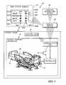
- FIG. 7is a diagrammatic and perspective view of a fourth embodiment of a bed status system in accordance with the present disclosure showing the bed status system in an example of use;
- FIG. 8is a diagrammatic view of one embodiment of a controller in accordance with the present disclosure.
- FIG. 9is a diagrammatic view of one embodiment of a location unit in accordance with the present disclosure.
- FIG. 10is a diagrammatic view of one embodiment of a bed status module in accordance with the present disclosure.
- FIG. 11is a diagrammatic view of a fifth embodiment of a bed status system in accordance with the present disclosure.
- FIG. 12is a diagrammatic view of a sixth embodiment of a bed status system in accordance with the present disclosure.
- a bed status system 10 in accordance with the present disclosureincludes a patient support apparatus 12 , a location unit 14 , and a bed status module 16 as shown in FIGS. 1 and 2 .
- the patient support apparatus 12is located, for example, in a patient room 18 of a healthcare facility.
- the location unit 14is coupled to a wall 181 of the patient room and configured to transmit a location of the location unit 14 to a predetermined area 22 of the patient room 18 .
- the bed status module 16is located outside the patient room 18 and is configured to receive the location of the patient support apparatus 12 when the patient support apparatus 12 is located in the predetermined area 22 of the patient room 18 .
- the bed status module 16is also configured to receive information from the patient support apparatus 12 that is indicative of a status of various pieces of equipment and processes included in the patient support apparatus as shown in FIGS. 1 and 2 .
- the bed status system 10is configured to provide a caregiver located outside a patient room 18 with information associated with a status of equipment and processes included in the patient support apparatus 12 without the caregiver entering the patient room 18 as suggested in FIG. 2 .
- a caregiver in a facilitymay look down a hallway 20 in the facility and receive information from multiple bed status modules 16 located in the hallway 20 as suggested in FIG. 2 .
- the caregiveris then able to determine the status of all equipment and processes included in all the patient support apparatuses on the hallway 20 .
- the caregivermay only visit those patient rooms with issues identified by the bed status system 10 , and thus, minimize time and resources wasted entering each patient room to check on the status of each patient support apparatus located in the patient room.
- the patient support apparatus 12includes a patient support surface 24 , a patient support structure 26 , and a control system 28 .
- the patient support structure 26rests on ground underlying the patient support surface and is movable relative to the ground.
- the patient support surface 24is coupled to the patient support structure 26 and is adapted to support the patient resting on the patient support apparatus 12 .
- Control system 28is coupled to both the patient support structure 26 and the patient support surface 24 to control movement of the patient support structure 26 relative to ground, configuration of the patient support surface 24 , communicate with external components, and determine statuses of equipment and processes include in the patient support apparatus 12 .
- the control system 28includes a controller 30 , a communication link 32 , and a sensor as suggested in FIG. 1 .
- Communication link 32is configured to receive signals from the location unit 14 and transmit those signals to the controller 30 for processing.
- the location unit 14is coupled to a headwall of the patient room 18 and transmits location data to the predetermined area 22 of the patient room 18 as shown in FIG. 2 .
- the communication link 32receives the location data and transmits the location data to the controller 30 .
- Controller 30is configured to receive information from equipment, processes, and sensors included in the patient support apparatus 12 .
- Equipmentmay include an inflatable mattress included in the patient support surface 24 , an actuator included in the patient support structure 26 , braking device included in the patient support structure, and any other suitable pieces of equipment.
- Processesmay include a process for detecting bed exit, a process for providing a microclimate to the patient support surface, a process for monitoring patient movement, and any other suitable process.
- Sensorsmay include a head angle sensor that determine an angle of the patient's back and head relative to ground, a wetness sensor that detects an incontinence event, and any other suitable sensors which may be coupled to the patient or the patient support apparatus.
- Controller 30receives the data from the equipment, processes, and equipment and then determines a status of the equipment, processes, and sensors included in the patient support apparatus 12 . Controller 30 communicates this apparatus data including the various statues to the bed status module 16 by way of the communication link 32 . Controller 30 also sends location data from the location unit 14 to the bed status module 16 . Bed status module 16 then combines the apparatus data and location data to cause information to be provided to caregiver that communicates the location and the status of the patient support apparatus 12 as suggested in FIG. 1 .
- the controller 30includes a processor 30 A, memory 30 B, one or more inputs 30 C, and one or more outputs 30 D as shown in FIG. 8 .
- Status informationmay be received by processor 30 A via inputs 30 C and stored in memory 30 B.
- processor 30 Amay execute various processes such as a bed exit alarm process which monitors various inputs to determine if the bed exit alarm should activated. Once the processor 30 A makes such a determination, the processor 30 A sends commands via outputs 30 D to cause an alarm to sound or a visual indicator to be displayed.
- a sensormay be one of the inputs 30 C.
- Outputs 30 D of controller 30may be couple to actuators, blowers, etc. to control various equipment and processes included in the patient support apparatus.
- the processor 30 Amay store information received from inputs 30 C for additional processing, collection of additional data, or communication via communication link 32 .
- the controller 30may further include a power supply 30 F as shown in FIG. 8 .
- the power supply 30 Fmay be a battery which supplies power to the processor 30 A.
- the power supply 30 Fmay also be a wire which is coupled to a power supply included in the patient support apparatus.
- the power supply 30 Fmay also include a transformer which provides power from the patient support apparatus or an electrical wall socket to the processor 516 A at an appropriate voltage and frequency.
- a patient 50has lowered a siderail 34 included in the patient support apparatus 12 and is attempting to egress from the patient support apparatus 12 as shown in FIG. 7 .
- the patienthas configured the patient support surface 24 to be firm increasing chances for the development of pressure ulcer formation on the patient 50 .
- the patient support structure 26has been lowered previously to its lowest position by a caregiver to minimize damage to the patient 50 from a fall should the patient 50 attempt to exit the patient support apparatus 12 .
- Controller 30provides apparatus data which includes a siderail position, a surface configuration, bed-exit alarms, and a patient support structure position.
- the controller 30communicates the apparatus data by way of the communication link 32 to the bed status module 16 which in turn causes visual indicators 301 , 302 , 303 , 304 associated with each piece of equipment to change to the appropriate visual indicator for the status.
- bed status module 16causes a first visual indicator 301 associated with the siderails to change from green, indicating a desired status, to red, indication an undesired status as a result of the siderail 34 being in a lowered position.
- the bed status module 16also causes a second visual indicator 302 to remain green as the patient support structure 26 is in the lowered position.
- Bed status module 16causes a third visual indicator 303 associated with a bed-exit alarm to change from green to red as controller 30 had determined the patient 50 is attempting to exit the patient support apparatus 12 . Finally, the bed status module 16 causes a fourth visual indicator 304 associated with the patient support surface 24 to change from green to red because the patient support surface 24 is in a firm configuration.
- the controller 30provides apparatus information which includes a status for siderail position, patient support structure position, bed exit alarm, and patient support surface status.
- the status of other equipment included in the patient support apparatus 12may also be included in the apparatus information.
- Such status informationmay include, an angle of a patient's back and head relative to the patient support structure, the occurrence of an incontinence event, environment conditions such as temperature and humidity between the patient and the patient support surface, failure of a patient to move during a predetermined time period, equipment failure on the patient support apparatus, and any other suitable events, equipment, or processes.
- the bed status module 16may also include an audio output 305 which may sound if one ore more of the statuses are in an undesirable state as shown in FIGS. 1 and 7 .
- the audio outputmay be the same when any status becomes undesirable or specific patterns of sound may be emitted when various combinations of status are undesirable.
- the location unit 14is configured to transmit location data to the predetermined area 22 in the patient room 18 .
- the location unit 14transmits the location data wirelessly.
- Wireless transmissionmay be achieved by emitting an infrared beam, sending a wireless signal over an 802.11 local area network, sending a wireless signal via BLUETOOTH® technology, or any other suitable alternative.
- the communication link 32 included in the patient support apparatus 12is configured to receive location data from the location unit 14 and send both location data and apparatus data to the bed status module 16 or other device.
- the communication link 32may be configured to receive an infrared beam, a wireless signal over an 802.11 local area network, a wireless signal via BLUETOOTH® technology, or any other suitable alternative from the location unit 14 .
- the communication link 32may also be configured to send apparatus to the bed status module wireless via a wireless signal over an 802.11 local area network, a wireless signal via BLUETOOTH® technology, or any other suitable alternative.
- the bed status module 16may be provide information associated with one or more patient support apparatuses included in a patient room.
- a first patient support apparatus 12 Ais located in the patient room 18 .
- a second patient support apparatus 12 Bis located in spaced-apart relation to the first patient support apparatus 16 A in the patient room 18 .
- a first location unit 14 Ais mounted on a wall 181 of the patient room 18 and is configured to send location data to a first predetermined area 22 A in the patient room 18 .
- a second location unit 14 Bis mounted in spaced-apart relation on the wall 181 of the patient room and is configured to send location data to a second predetermined area 22 B in the patient room.
- Both patient support apparatuses 12 A, 12 Breceive location data from their associated location units 14 A, 14 B and then communicate associated apparatus data and location data to the bed status module 16 which is located in the hallway 20 .
- the bed status module 16may be configured to show a first set 36 A of visual indicators associated with the status of the first patient support apparatus 12 A when the first patient support apparatus 12 A is in the first predetermined area 22 A.
- the first set 36 A of visual indicatorsmay include first, second, third, and fourth visual indicators 301 A, 302 A, 303 A, 304 A associated with various equipment and programs included in the first patient support apparatus 12 A.
- the bed status module 16may also show a second set 36 B of visual indicators associated with the status of the second patient support apparatus 12 B when the second patient support apparatus 12 B is in the second predetermined area 22 B.
- the second set 36 B of visual indicatorsmay include first, second, third, and fourth visual indicators 301 B, 302 B, 303 B, 304 B associated with various equipment and programs included in the second patient support apparatus 12 B.
- the bed status system 110includes the patient support apparatus 12 , the location unit 14 , the bed status module 16 , and a remote server 138 .
- the controller 30 included in the patient support apparatus 12receives location data from the location unit 14 and determines apparatus data from the patient support apparatus 12 .
- the controller 30then communicates the location and apparatus data to the communication link 32 which sends the data to the remote server 138 as shown in FIG. 3 .
- the remote server 138may process the location data and the apparatus data and provide specific signals to the bed status module 16 .
- the bed status moduleonly includes relays which cause the sets 36 A, 36 B of visual indicators to change to the proper status.
- the remote server 138may also store the location and apparatus data for future review and auditing. As shown in FIG. 3 , the remote server 138 may also send the location and apparatus data to a hospital information system 40 where the data may be archived or entered into an electronic medical record associated with the patient.
- the bed status system 210includes the patient support apparatus 12 , the location unit 14 , and the bed status module 16 .
- the controller 30 included in the patient support apparatus 12receives location data from the location unit 14 via a wire 38 and determines apparatus data from the patient support apparatus 12 .
- the controller 30then communicates the location and apparatus data to the communication link 32 which sends the data to the remote server 138 via another wire 42 as shown in FIG. 4 .
- the location unit 14 and the communication link 32may be configured for wireless communication, they may also be configured to communicate across wired connections as shown in FIG. 4 .
- a first embodiment of the bed status module 16is shown for example in FIG. 5 .
- the bed status module 16may be located in the hallway 20 and coupled to a wall 44 above a doorway 46 that leads to the patient room 18 .
- the bed status module 16may be configured to communicate information about each patient support apparatus located in the patient room 18 to caregivers located outside the patient room 18 .
- the bed status module 16includes the first set 36 A of visual indicators 301 A, 302 A, 303 A, 304 A associated with the first patient support apparatus 12 A.
- the bed status module 16further includes the second set 36 B of visual indicators 301 B, 302 B, 303 B, 304 B associated with the second patient support apparatus 12 B.
- the bed status module 16also includes the audio output 305 .
- the bed status module 16may be used with any combination of bed status systems 10 , 110 , and 210 .
- FIG. 6Another embodiment of a bed status module 116 is shown in FIG. 6 .
- the bed status module 116is located in the hallway 20 and coupled to the wall 44 above the doorway 46 that leads to the patient room 18 .
- the bed status module 16is configured to communicate information about each patient support apparatus located in the patient room 18 to caregivers located outside the patient room 18 .
- this bed status module 116only provides an overall visual indicator for each patient support apparatus.
- the first patient support apparatus 12 Ahas a green visual indicator 116 A which means the status of all equipment and processes included in the first patient support apparatus are in a desirable state.
- the second patient support apparatus 12 Bhas a red visual indicator 116 B which means that at least one of the pieces of equipment or processes in the patient support apparatus have an undesirable status.
- the overall visual indicator 116 B for the second patient support apparatusis red.
- the bed status module 116may also include the audio output 305 .
- the bed status module 116may be used with any combination of bed status systems 10 , 110 , and 210 .
- the location unit 614is known as a smart location unit 614 as a result of the location unit 614 including a processor 614 A, memory 614 B, one or more inputs 614 C, and one or more outputs 614 D as shown in FIG. 9 .
- the apparatus datamay be communicated to the processor 614 A of the location unit 614 via one of the inputs 614 C.
- the location unit 614may communicate the location data via one of the outputs 614 D to the bed status module or the patient support apparatus.
- the location datamay be stored on the memory 614 B along with instructions for sending the location data to the predetermined area 22 . These instructions may include location, frequency, and information to be provided in the location data.
- the location unitmay also be a dumb location unit in which no processing occurs other than the communication of location data and relay of apparatus data.
- the location unit 614may further include a power supply 614 F as shown in FIG. 9 .
- the power supply 614 Fmay be a battery which supplies power to the processor 614 A.
- the power supply 614 Fmay also be a transformer and a power cord which provides power from an electrical wall socket to the transformer which provides power to the processor 614 A at an appropriate voltage and frequency.
- the bed status system 410includes the patient support apparatus 12 , a location unit 414 , and the bed status module 16 .
- the controller 30 included in the patient support apparatus 12provides apparatus data to the location unit 414 .
- the controller 30communicates wirelessly with the location unit 414 via the communication link 32 as shown in FIG. 11 .
- the location unit 414receives the apparatus data and provides both the apparatus data and location data to the bed status module 414 .
- the location unit 414may communicate with the bed status module wirelessly. While the location unit 14 and the communication link 32 may be configured for wireless communication, they may also be configured to communicate across wired connections as suggested in FIG. 4 .
- the bed status system 510includes the patient support apparatus 512 , a location unit 514 , and the bed status module 516 .
- the patient support apparatus 512is configured to provide apparatus data that includes status of various pieces of equipment and processes in the patient support apparatus 512 and an apparatus ID 502 which includes information which identifies the patient support apparatus.
- the controller 30 included in the patient support apparatus 512provides apparatus data, including the apparatus ID 502 , to the bed status system 510 .
- the location unit 514receives the apparatus ID 502 from the patient support apparatus 512 when the patient support apparatus 512 is in the predetermined area 22 .
- the location unit 514then communicates the location data and the apparatus ID 502 to the bed status module 516 as suggested in FIG. 12 .
- the bed status module 516receives the apparatus data, the location data, and the apparatus ID 502 from the patient support apparatus 512 and the location unit 514 as shown in FIG. 12 .
- the bed status modulethen combines the apparatus ID 502 received with the location data with the apparatus ID 502 received with the apparatus data and to cause the appropriate visual indicators to be displayed as suggested in FIG. 14 .
- the bed status module 516is known as a smart bed status module as a result of the bed status module 516 including a processor 516 A, memory 516 B, one or more inputs 516 C, and one or more outputs 516 D as shown in FIG. 10 .
- the apparatus data and the location datamay be received via inputs 516 C, processed by the processor 516 A, and stored in the memory 516 B.
- the processor 516 Awhen receiving apparatus data, may look up which visual indicators should be displayed in a table stored in the memory 516 B.
- the processor 516 Athen sends commands via one or more outputs 516 D that causes the appropriate visual indicators to
- the bed status module 516may also include a user interface 516 E which is coupled to the processor 516 A.
- the user interface 516 Emay be configured to display the visual indicators suggested in FIGS. 1-7, 11, and 12 .
- the user interface 516may also be configured to receive user input and communicate the user input back to the processor 516 A.
- the user interfacemay, in one illustrative example, be a touch screen interface which both provides visual output but also receives user input.
- the user interfacemay display that the bed egress alarm has been tripped.
- the caregivermay provide a delay input to the user interface 516 E of the bed status module 516 that causes the visual indicator associated with the bed egress alarm to be reset, put on hold for a predetermined period of time, or forwarded to another caregiver.
- the bed status modulemay also be a dumb bed status module in which no processing occurs other than the providing the appropriate visual indicator in response to receiving the location and apparatus data.
- the bed status module 516may further include a power supply 516 F as shown in FIG. 10 .
- the power supply 516 Fmay be a battery which supplies power to the processor 516 A.
- the power supply 516 Fmay also be a transformer and a power cord which provides power from an electrical wall socket to the transformer which provides power to the processor 516 A at an appropriate voltage and frequency.
Landscapes
- Health & Medical Sciences (AREA)
- Business, Economics & Management (AREA)
- Engineering & Computer Science (AREA)
- Life Sciences & Earth Sciences (AREA)
- Physics & Mathematics (AREA)
- Public Health (AREA)
- General Health & Medical Sciences (AREA)
- General Physics & Mathematics (AREA)
- Emergency Management (AREA)
- Veterinary Medicine (AREA)
- Animal Behavior & Ethology (AREA)
- General Business, Economics & Management (AREA)
- Medical Informatics (AREA)
- Biomedical Technology (AREA)
- Nursing (AREA)
- Epidemiology (AREA)
- Primary Health Care (AREA)
- Computer Security & Cryptography (AREA)
- Pathology (AREA)
- Biophysics (AREA)
- Molecular Biology (AREA)
- Heart & Thoracic Surgery (AREA)
- Surgery (AREA)
- Oral & Maxillofacial Surgery (AREA)
- Dentistry (AREA)
- Physiology (AREA)
- Automation & Control Theory (AREA)
- Invalid Beds And Related Equipment (AREA)
- Measuring And Recording Apparatus For Diagnosis (AREA)
- Alarm Systems (AREA)
Abstract
Description
Claims (20)
Priority Applications (1)
| Application Number | Priority Date | Filing Date | Title |
|---|---|---|---|
| US14/870,196US9489818B2 (en) | 2012-12-28 | 2015-09-30 | Bed status system for a patient support apparatus |
Applications Claiming Priority (3)
| Application Number | Priority Date | Filing Date | Title |
|---|---|---|---|
| US201261746742P | 2012-12-28 | 2012-12-28 | |
| US14/136,214US9177465B2 (en) | 2012-12-28 | 2013-12-20 | Bed status system for a patient support apparatus |
| US14/870,196US9489818B2 (en) | 2012-12-28 | 2015-09-30 | Bed status system for a patient support apparatus |
Related Parent Applications (1)
| Application Number | Title | Priority Date | Filing Date |
|---|---|---|---|
| US14/136,214ContinuationUS9177465B2 (en) | 2012-12-28 | 2013-12-20 | Bed status system for a patient support apparatus |
Publications (2)
| Publication Number | Publication Date |
|---|---|
| US20160019771A1 US20160019771A1 (en) | 2016-01-21 |
| US9489818B2true US9489818B2 (en) | 2016-11-08 |
Family
ID=49958196
Family Applications (2)
| Application Number | Title | Priority Date | Filing Date |
|---|---|---|---|
| US14/136,214Active2034-02-06US9177465B2 (en) | 2012-12-28 | 2013-12-20 | Bed status system for a patient support apparatus |
| US14/870,196ActiveUS9489818B2 (en) | 2012-12-28 | 2015-09-30 | Bed status system for a patient support apparatus |
Family Applications Before (1)
| Application Number | Title | Priority Date | Filing Date |
|---|---|---|---|
| US14/136,214Active2034-02-06US9177465B2 (en) | 2012-12-28 | 2013-12-20 | Bed status system for a patient support apparatus |
Country Status (3)
| Country | Link |
|---|---|
| US (2) | US9177465B2 (en) |
| EP (1) | EP2750060A1 (en) |
| BR (1) | BR102013033927A2 (en) |
Cited By (7)
| Publication number | Priority date | Publication date | Assignee | Title |
|---|---|---|---|---|
| US20140080413A1 (en)* | 2012-09-17 | 2014-03-20 | Stryker Corporation | Communication systems for patient support apparatuses |
| US10489661B1 (en) | 2016-03-08 | 2019-11-26 | Ocuvera LLC | Medical environment monitoring system |
| US10600204B1 (en) | 2016-12-28 | 2020-03-24 | Ocuvera | Medical environment bedsore detection and prevention system |
| US10786408B2 (en) | 2014-10-17 | 2020-09-29 | Stryker Corporation | Person support apparatuses with exit detection systems |
| US12186241B2 (en) | 2021-01-22 | 2025-01-07 | Hill-Rom Services, Inc. | Time-based wireless pairing between a medical device and a wall unit |
| US12279999B2 (en) | 2021-01-22 | 2025-04-22 | Hill-Rom Services, Inc. | Wireless configuration and authorization of a wall unit that pairs with a medical device |
| US12408845B2 (en) | 2019-08-20 | 2025-09-09 | Stryker Corporation | Person support apparatus with adjustable exit detection zones |
Families Citing this family (14)
| Publication number | Priority date | Publication date | Assignee | Title |
|---|---|---|---|---|
| US9838836B2 (en)* | 2005-03-29 | 2017-12-05 | Stryker Corporation | Patient support apparatus communication systems |
| US9937090B2 (en)* | 2005-03-29 | 2018-04-10 | Stryker Corporation | Patient support apparatus communication systems |
| US9177465B2 (en) | 2012-12-28 | 2015-11-03 | Hill-Rom Services, Inc. | Bed status system for a patient support apparatus |
| US20160307429A1 (en) | 2015-04-14 | 2016-10-20 | Hill-Rom Services, Inc. | Monitoring of patient supports |
| DE102015208215B4 (en) | 2015-05-04 | 2024-05-02 | Stabilus Gmbh | Electromechanical control arrangement for a chair |
| US11631480B1 (en) | 2015-08-03 | 2023-04-18 | Specialized Communications, Inc. | Communications system, devices, methods, and techniques |
| US10500401B2 (en)* | 2016-12-06 | 2019-12-10 | Stryker Corporation | Network communication for patient support apparatuses |
| US11172892B2 (en) | 2017-01-04 | 2021-11-16 | Hill-Rom Services, Inc. | Patient support apparatus having vital signs monitoring and alerting |
| US12154685B2 (en) | 2018-12-19 | 2024-11-26 | Stryker Corporation | System for managing patient support apparatuses and clinical rounds |
| CN112972154B (en)* | 2018-12-27 | 2022-04-15 | 艾感科技(广东)有限公司 | A method of early warning based on percussion signal |
| US11406287B2 (en) | 2019-03-29 | 2022-08-09 | Stryker Corporation | System for managing patient support apparatuses and bed sore risks |
| US11062585B2 (en) | 2019-03-29 | 2021-07-13 | Stryker Corporation | Patient care system |
| AU2020308856B2 (en) | 2019-06-28 | 2025-10-02 | Stryker Corporation | Caregiver assistance system |
| US12267710B2 (en)* | 2021-07-05 | 2025-04-01 | Mediatek Inc. | Method for configuring channel state information computation period for high mobility |
Citations (57)
| Publication number | Priority date | Publication date | Assignee | Title |
|---|---|---|---|---|
| US3991414A (en) | 1971-08-02 | 1976-11-09 | Moran Jack L | Health care signaling device |
| US4135241A (en) | 1971-02-22 | 1979-01-16 | Medelco, Incorporated | Inventory control, bed allocation and accounting data handling system |
| US4261109A (en) | 1979-09-26 | 1981-04-14 | Exxon Research & Engineering Company | Method and apparatus for controlling the operation of a magnetically stabilized fluidized bed by magnetic field measurement |
| US5561412A (en) | 1993-07-12 | 1996-10-01 | Hill-Rom, Inc. | Patient/nurse call system |
| US5699038A (en) | 1993-07-12 | 1997-12-16 | Hill-Rom, Inc. | Bed status information system for hospital beds |
| US5715548A (en) | 1994-01-25 | 1998-02-10 | Hill-Rom, Inc. | Chair bed |
| US5771511A (en) | 1995-08-04 | 1998-06-30 | Hill-Rom, Inc. | Communication network for a hospital bed |
| US5838223A (en) | 1993-07-12 | 1998-11-17 | Hill-Rom, Inc. | Patient/nurse call system |
| US6208250B1 (en) | 1999-03-05 | 2001-03-27 | Hill-Rom, Inc. | Patient position detection apparatus for a bed |
| US6566833B2 (en) | 2001-03-29 | 2003-05-20 | Kci Licensing, Inc. | Prone positioning therapeutic bed |
| US6611979B2 (en) | 1997-09-23 | 2003-09-02 | Hill-Rom Services, Inc. | Mattress having a retractable foot section |
| US6791460B2 (en) | 1999-03-05 | 2004-09-14 | Hill-Rom Services, Inc. | Patient position detection apparatus for a bed |
| US6876303B2 (en) | 2000-05-05 | 2005-04-05 | Hill-Rom Services, Inc. | Hospital monitoring and control system and method |
| US6897780B2 (en) | 1993-07-12 | 2005-05-24 | Hill-Rom Services, Inc. | Bed status information system for hospital beds |
| US6988012B2 (en) | 2001-09-24 | 2006-01-17 | Siemens Aktiengesellschaft | Medical-technical system and operating method therefor |
| US7017208B2 (en) | 1995-08-04 | 2006-03-28 | Hill-Rom Services, Inc. | Hospital bed |
| US7017211B2 (en) | 2001-03-29 | 2006-03-28 | Kci Licensing, Inc. | Head restraint for therapeutic bed |
| US7092376B2 (en)* | 2001-03-30 | 2006-08-15 | Hill-Rom Services, Inc. | Hospital bed and network system |
| US7126467B2 (en) | 2004-07-23 | 2006-10-24 | Innovalarm Corporation | Enhanced fire, safety, security, and health monitoring and alarm response method, system and device |
| US7129833B2 (en) | 2004-07-23 | 2006-10-31 | Innovalarm Corporation | Enhanced fire, safety, security and health monitoring and alarm response method, system and device |
| US7148797B2 (en) | 2004-07-23 | 2006-12-12 | Innovalarm Corporation | Enhanced fire, safety, security and health monitoring and alarm response method, system and device |
| US7154397B2 (en) | 2001-08-03 | 2006-12-26 | Hill Rom Services, Inc. | Patient point-of-care computer system |
| US7170404B2 (en) | 2004-07-23 | 2007-01-30 | Innovalarm Corporation | Acoustic alert communication system with enhanced signal to noise capabilities |
| US7173525B2 (en) | 2004-07-23 | 2007-02-06 | Innovalarm Corporation | Enhanced fire, safety, security and health monitoring and alarm response method, system and device |
| US7319386B2 (en) | 2004-08-02 | 2008-01-15 | Hill-Rom Services, Inc. | Configurable system for alerting caregivers |
| US7343302B2 (en) | 2002-02-11 | 2008-03-11 | Puresense Environmental Inc. | System and method for emergency response |
| US7629890B2 (en) | 2003-12-04 | 2009-12-08 | Hoana Medical, Inc. | System and methods for intelligent medical vigilance with bed exit detection |
| US7656287B2 (en) | 2004-07-23 | 2010-02-02 | Innovalarm Corporation | Alert system with enhanced waking capabilities |
| US7654948B2 (en) | 2003-02-28 | 2010-02-02 | Consolidate Research of Richmond, Inc. | Automated insomnia treatment system |
| US7690059B2 (en) | 2005-12-19 | 2010-04-06 | Stryker Corporation | Hospital bed |
| US7813941B2 (en) | 2006-07-26 | 2010-10-12 | Siemens Medical Solutions Usa, Inc. | Patient bed search system |
| US7834768B2 (en) | 1999-03-05 | 2010-11-16 | Hill-Rom Services, Inc. | Obstruction detection apparatus for a bed |
| US7852208B2 (en) | 2004-08-02 | 2010-12-14 | Hill-Rom Services, Inc. | Wireless bed connectivity |
| US7868740B2 (en) | 2007-08-29 | 2011-01-11 | Hill-Rom Services, Inc. | Association of support surfaces and beds |
| US7971300B2 (en) | 2007-10-09 | 2011-07-05 | Hill-Rom Services, Inc. | Air control system for therapeutic support surfaces |
| US8000977B2 (en) | 2004-03-11 | 2011-08-16 | Healthcare Charities, Inc. | System and method to develop health-care information systems |
| US7996935B1 (en) | 2010-03-17 | 2011-08-16 | Libin Chen | Credible and light foldable hanging bed |
| US8046625B2 (en) | 2008-02-22 | 2011-10-25 | Hill-Rom Services, Inc. | Distributed fault tolerant architecture for a healthcare communication system |
| US8082160B2 (en) | 2007-10-26 | 2011-12-20 | Hill-Rom Services, Inc. | System and method for collection and communication of data from multiple patient care devices |
| US8121856B2 (en) | 2005-06-28 | 2012-02-21 | Hill-Rom Services, Inc. | Remote access to healthcare device diagnostic information |
| US8266742B2 (en) | 2010-12-06 | 2012-09-18 | Hill-Rom Services, Inc. | Biometric bed configuration |
| US8280748B2 (en) | 2006-10-20 | 2012-10-02 | Hill-Rom Services, Inc. | Bed management |
| US8314781B2 (en) | 2010-02-26 | 2012-11-20 | Hill-Rom Services, Inc. | Hospital bed having multiple touchscreen displays |
| US8334777B2 (en)* | 2010-02-19 | 2012-12-18 | Hill-Rom Services, Inc. | Patient room and bed management apparatus and system |
| US8432287B2 (en) | 2010-07-30 | 2013-04-30 | Hill-Rom Services, Inc. | Apparatus for controlling room lighting in response to bed exit |
| US8461968B2 (en) | 2007-08-29 | 2013-06-11 | Hill-Rom Services, Inc. | Mattress for a hospital bed for use in a healthcare facility and management of same |
| US8512221B2 (en) | 2003-02-28 | 2013-08-20 | Consolidated Research Of Richmond, Inc. | Automated treatment system for sleep |
| US8525680B2 (en) | 2009-09-18 | 2013-09-03 | Hill-Rom Services, Inc. | Apparatuses for supporting and monitoring a condition of a person |
| US8537008B2 (en) | 2008-09-19 | 2013-09-17 | Hill-Rom Services, Inc. | Bed status indicators |
| US8544126B2 (en)* | 2005-12-19 | 2013-10-01 | Stryker Corporation | Patient support with improved control |
| US8560580B1 (en) | 1999-05-10 | 2013-10-15 | Teletracking Technologies, Inc. | Visual display of room information |
| US8571884B2 (en) | 2008-06-13 | 2013-10-29 | Aionex, Inc. | Healthcare communication and workflow management system and method |
| US8572778B2 (en) | 2007-03-30 | 2013-11-05 | Hill-Rom Services, Inc. | User interface for hospital bed |
| US8612252B1 (en) | 2008-02-25 | 2013-12-17 | Allscripts Software, Llc | Care management and transportation workflow |
| US8634981B1 (en) | 2012-09-28 | 2014-01-21 | Elwha Llc | Automated systems, devices, and methods for transporting and supporting patients |
| US20140184409A1 (en) | 2012-12-28 | 2014-07-03 | Hill-Rom Services, Inc. | Bed status system for a patient support apparatus |
| US8799011B2 (en) | 2010-02-19 | 2014-08-05 | Hill-Rom Services, Inc. | Patient room and bed management apparatus and system |
- 2013
- 2013-12-20USUS14/136,214patent/US9177465B2/enactiveActive
- 2013-12-23EPEP13199451.9Apatent/EP2750060A1/ennot_activeWithdrawn
- 2013-12-30BRBR102013033927Apatent/BR102013033927A2/ennot_activeApplication Discontinuation
- 2015
- 2015-09-30USUS14/870,196patent/US9489818B2/enactiveActive
Patent Citations (126)
| Publication number | Priority date | Publication date | Assignee | Title |
|---|---|---|---|---|
| US4135241A (en) | 1971-02-22 | 1979-01-16 | Medelco, Incorporated | Inventory control, bed allocation and accounting data handling system |
| US3991414A (en) | 1971-08-02 | 1976-11-09 | Moran Jack L | Health care signaling device |
| US4261109A (en) | 1979-09-26 | 1981-04-14 | Exxon Research & Engineering Company | Method and apparatus for controlling the operation of a magnetically stabilized fluidized bed by magnetic field measurement |
| US5561412A (en) | 1993-07-12 | 1996-10-01 | Hill-Rom, Inc. | Patient/nurse call system |
| US5699038A (en) | 1993-07-12 | 1997-12-16 | Hill-Rom, Inc. | Bed status information system for hospital beds |
| US6362725B1 (en) | 1993-07-12 | 2002-03-26 | Hill-Rom Services, Inc. | Bed status information system for hospital beds |
| US5838223A (en) | 1993-07-12 | 1998-11-17 | Hill-Rom, Inc. | Patient/nurse call system |
| US6147592A (en) | 1993-07-12 | 2000-11-14 | Hill-Rom, Inc. | Bed status information system for hospital beds |
| US6897780B2 (en) | 1993-07-12 | 2005-05-24 | Hill-Rom Services, Inc. | Bed status information system for hospital beds |
| US7538659B2 (en) | 1993-07-12 | 2009-05-26 | Hill-Rom Services, Inc. | Bed status information system for hospital beds |
| US7242308B2 (en) | 1993-07-12 | 2007-07-10 | Hill-Rom Services, Inc. | Bed status information system for hospital beds |
| US5715548A (en) | 1994-01-25 | 1998-02-10 | Hill-Rom, Inc. | Chair bed |
| US6163903A (en) | 1994-01-25 | 2000-12-26 | Hill-Rom Inc. | Chair bed |
| US6336235B1 (en) | 1994-01-25 | 2002-01-08 | Hill-Rom Services, Inc. | Chair bed |
| US5771511A (en) | 1995-08-04 | 1998-06-30 | Hill-Rom, Inc. | Communication network for a hospital bed |
| US7480951B2 (en) | 1995-08-04 | 2009-01-27 | Hill-Rom Services, Inc. | Patient care bed with network |
| US7213279B2 (en) | 1995-08-04 | 2007-05-08 | Weismiller Matthew W | Hospital bed and mattress having extendable foot section |
| US6279183B1 (en) | 1995-08-04 | 2001-08-28 | Hill-Rom, Inc. | Communication network for a hospital bed |
| US8065764B2 (en) | 1995-08-04 | 2011-11-29 | Hill-Rom Services, Inc. | Hospital bed |
| US7568246B2 (en) | 1995-08-04 | 2009-08-04 | Hill-Rom Services, Inc. | Bed with a networked alarm |
| US8413274B2 (en) | 1995-08-04 | 2013-04-09 | Hill-Rom Services, Inc. | Hospital bed |
| US7784128B2 (en) | 1995-08-04 | 2010-08-31 | Hill-Rom Services, Inc. | Hospital bed |
| US7237287B2 (en) | 1995-08-04 | 2007-07-03 | Hill-Rom Services, Inc. | Patient care bed with network |
| US7017208B2 (en) | 1995-08-04 | 2006-03-28 | Hill-Rom Services, Inc. | Hospital bed |
| US6611979B2 (en) | 1997-09-23 | 2003-09-02 | Hill-Rom Services, Inc. | Mattress having a retractable foot section |
| US8525682B2 (en) | 1999-03-05 | 2013-09-03 | Hill-Rom Services, Inc. | Hospital bed having alert light |
| US7834768B2 (en) | 1999-03-05 | 2010-11-16 | Hill-Rom Services, Inc. | Obstruction detection apparatus for a bed |
| US7978084B2 (en) | 1999-03-05 | 2011-07-12 | Hill-Rom Services, Inc. | Body position monitoring system |
| US7986242B2 (en) | 1999-03-05 | 2011-07-26 | Hill-Rom Services, Inc. | Electrical connector assembly suitable for a bed footboard |
| US6791460B2 (en) | 1999-03-05 | 2004-09-14 | Hill-Rom Services, Inc. | Patient position detection apparatus for a bed |
| US8400311B2 (en) | 1999-03-05 | 2013-03-19 | Hill-Rom Services, Inc. | Hospital bed having alert light |
| US8258963B2 (en) | 1999-03-05 | 2012-09-04 | Hill-Rom Services, Inc. | Body position monitoring system |
| US6320510B2 (en) | 1999-03-05 | 2001-11-20 | Douglas J. Menkedick | Bed control apparatus |
| US6208250B1 (en) | 1999-03-05 | 2001-03-27 | Hill-Rom, Inc. | Patient position detection apparatus for a bed |
| US8560580B1 (en) | 1999-05-10 | 2013-10-15 | Teletracking Technologies, Inc. | Visual display of room information |
| US6880189B2 (en) | 1999-12-29 | 2005-04-19 | Hill-Rom Services, Inc. | Patient support |
| US7454805B2 (en) | 1999-12-29 | 2008-11-25 | Hill-Rom Services, Inc. | Hospital bed |
| US7171708B2 (en) | 1999-12-29 | 2007-02-06 | Hill-Rom Services, Inc. | Foot controls for a bed |
| US6978500B2 (en) | 1999-12-29 | 2005-12-27 | Hill-Rom Services, Inc. | Foot controls for a bed |
| US6957461B2 (en) | 1999-12-29 | 2005-10-25 | Hill-Rom Services, Inc. | Hospital bed |
| US6691346B2 (en) | 1999-12-29 | 2004-02-17 | Hill-Rom Services, Inc. | Foot controls for a bed |
| US6658680B2 (en) | 1999-12-29 | 2003-12-09 | Hill-Rom Services, Inc. | Hospital bed |
| USRE43193E1 (en) | 1999-12-29 | 2012-02-21 | Hill-Rom Services, Inc. | Hospital bed |
| US8151387B2 (en) | 1999-12-29 | 2012-04-10 | Hill-Rom Services, Inc. | Hospital bed frame |
| US6876303B2 (en) | 2000-05-05 | 2005-04-05 | Hill-Rom Services, Inc. | Hospital monitoring and control system and method |
| US7443302B2 (en) | 2000-05-05 | 2008-10-28 | Hill-Rom Services, Inc. | Caregiver and equipment monitoring and control system |
| US8258965B2 (en) | 2000-05-05 | 2012-09-04 | Hill-Rom Services, Inc. | System for monitoring caregivers and equipment at a patient location |
| US8026821B2 (en) | 2000-05-05 | 2011-09-27 | Hill-Rom Services, Inc. | System for monitoring caregivers and equipment at a patient location |
| US8487774B2 (en) | 2000-05-05 | 2013-07-16 | Hill-Rom Services, Inc. | System for monitoring caregivers and equipment |
| US7472440B2 (en) | 2001-03-29 | 2009-01-06 | Kci Licensing, Inc. | Control member for therapeutic bed |
| US6566833B2 (en) | 2001-03-29 | 2003-05-20 | Kci Licensing, Inc. | Prone positioning therapeutic bed |
| US7017211B2 (en) | 2001-03-29 | 2006-03-28 | Kci Licensing, Inc. | Head restraint for therapeutic bed |
| US7715387B2 (en) | 2001-03-30 | 2010-05-11 | Hill-Rom Services, Inc. | Healthcare computer system with intra-room network |
| US7092376B2 (en)* | 2001-03-30 | 2006-08-15 | Hill-Rom Services, Inc. | Hospital bed and network system |
| US7831447B2 (en) | 2001-03-30 | 2010-11-09 | Hill-Rom Services, Inc. | Healthcare computer system |
| US7315535B2 (en) | 2001-03-30 | 2008-01-01 | Hill-Rom Services, Inc. | Information management system for bed data |
| US7154397B2 (en) | 2001-08-03 | 2006-12-26 | Hill Rom Services, Inc. | Patient point-of-care computer system |
| US7679520B2 (en) | 2001-08-03 | 2010-03-16 | Hill-Rom Services, Inc. | Patient point-of-care computer system |
| US8674839B2 (en) | 2001-08-03 | 2014-03-18 | Hill-Rom Services, Inc. | Hospital bed computer system for control of patient room environment |
| US8334779B2 (en) | 2001-08-03 | 2012-12-18 | Hill-Rom Services, Inc. | Touch screen control of a hospital bed |
| US7911349B2 (en) | 2001-08-03 | 2011-03-22 | Hill-Rom Services, Inc. | Hospital bed computer system |
| US8368545B2 (en) | 2001-08-03 | 2013-02-05 | Hill-Rom Services, Inc. | Hospital bed computer system with pharmacy interaction |
| US6988012B2 (en) | 2001-09-24 | 2006-01-17 | Siemens Aktiengesellschaft | Medical-technical system and operating method therefor |
| US7343302B2 (en) | 2002-02-11 | 2008-03-11 | Puresense Environmental Inc. | System and method for emergency response |
| US8512221B2 (en) | 2003-02-28 | 2013-08-20 | Consolidated Research Of Richmond, Inc. | Automated treatment system for sleep |
| US7654948B2 (en) | 2003-02-28 | 2010-02-02 | Consolidate Research of Richmond, Inc. | Automated insomnia treatment system |
| US7629890B2 (en) | 2003-12-04 | 2009-12-08 | Hoana Medical, Inc. | System and methods for intelligent medical vigilance with bed exit detection |
| US8000977B2 (en) | 2004-03-11 | 2011-08-16 | Healthcare Charities, Inc. | System and method to develop health-care information systems |
| US7477144B2 (en) | 2004-07-23 | 2009-01-13 | Innovalarm Corporation | Breathing sound monitoring and alarm response method, system and device |
| US7477143B2 (en) | 2004-07-23 | 2009-01-13 | Innovalarm Corporation | Enhanced personal monitoring and alarm response method and system |
| US7170404B2 (en) | 2004-07-23 | 2007-01-30 | Innovalarm Corporation | Acoustic alert communication system with enhanced signal to noise capabilities |
| US7391316B2 (en) | 2004-07-23 | 2008-06-24 | Innovalarm Corporation | Sound monitoring screen savers for enhanced fire, safety, security and health monitoring |
| US7126467B2 (en) | 2004-07-23 | 2006-10-24 | Innovalarm Corporation | Enhanced fire, safety, security, and health monitoring and alarm response method, system and device |
| US7403110B2 (en) | 2004-07-23 | 2008-07-22 | Innovalarm Corporation | Enhanced alarm monitoring using a sound monitoring screen saver |
| US7173525B2 (en) | 2004-07-23 | 2007-02-06 | Innovalarm Corporation | Enhanced fire, safety, security and health monitoring and alarm response method, system and device |
| US7656287B2 (en) | 2004-07-23 | 2010-02-02 | Innovalarm Corporation | Alert system with enhanced waking capabilities |
| US7129833B2 (en) | 2004-07-23 | 2006-10-31 | Innovalarm Corporation | Enhanced fire, safety, security and health monitoring and alarm response method, system and device |
| US7508307B2 (en) | 2004-07-23 | 2009-03-24 | Innovalarm Corporation | Home health and medical monitoring method and service |
| US7148797B2 (en) | 2004-07-23 | 2006-12-12 | Innovalarm Corporation | Enhanced fire, safety, security and health monitoring and alarm response method, system and device |
| US7522035B2 (en) | 2004-07-23 | 2009-04-21 | Innovalarm Corporation | Enhanced bedside sound monitoring and alarm response method, system and device |
| US8421606B2 (en) | 2004-08-02 | 2013-04-16 | Hill-Rom Services, Inc. | Wireless bed locating system |
| US7746218B2 (en) | 2004-08-02 | 2010-06-29 | Hill-Rom Services, Inc. | Configurable system for alerting caregivers |
| US8120471B2 (en) | 2004-08-02 | 2012-02-21 | Hill-Rom Services, Inc. | Hospital bed with network interface unit |
| US8536990B2 (en) | 2004-08-02 | 2013-09-17 | Hill-Rom Services, Inc. | Hospital bed with nurse call system interface unit |
| US8284047B2 (en) | 2004-08-02 | 2012-10-09 | Hill-Rom Services, Inc. | Wireless bed connectivity |
| US8604917B2 (en) | 2004-08-02 | 2013-12-10 | Hill-Rom Services, Inc. | Hospital bed having user input to enable and suspend remote monitoring of alert conditions |
| US7319386B2 (en) | 2004-08-02 | 2008-01-15 | Hill-Rom Services, Inc. | Configurable system for alerting caregivers |
| US8344860B2 (en) | 2004-08-02 | 2013-01-01 | Hill-Rom Services, Inc. | Patient support apparatus alert system |
| US7852208B2 (en) | 2004-08-02 | 2010-12-14 | Hill-Rom Services, Inc. | Wireless bed connectivity |
| US8121856B2 (en) | 2005-06-28 | 2012-02-21 | Hill-Rom Services, Inc. | Remote access to healthcare device diagnostic information |
| US8393026B2 (en) | 2005-11-07 | 2013-03-12 | Stryker Corporation | Hospital bed |
| US7805784B2 (en) | 2005-12-19 | 2010-10-05 | Stryker Corporation | Hospital bed |
| US8544126B2 (en)* | 2005-12-19 | 2013-10-01 | Stryker Corporation | Patient support with improved control |
| US7690059B2 (en) | 2005-12-19 | 2010-04-06 | Stryker Corporation | Hospital bed |
| US7962981B2 (en) | 2005-12-19 | 2011-06-21 | Stryker Corporation | Hospital bed |
| US7861334B2 (en) | 2005-12-19 | 2011-01-04 | Stryker Corporation | Hospital bed |
| US8219416B2 (en) | 2006-07-26 | 2012-07-10 | Siemens Medical Solutions Usa, Inc. | Patient bed search and management system |
| US7813941B2 (en) | 2006-07-26 | 2010-10-12 | Siemens Medical Solutions Usa, Inc. | Patient bed search system |
| US8280748B2 (en) | 2006-10-20 | 2012-10-02 | Hill-Rom Services, Inc. | Bed management |
| US8572778B2 (en) | 2007-03-30 | 2013-11-05 | Hill-Rom Services, Inc. | User interface for hospital bed |
| US8604916B2 (en) | 2007-08-29 | 2013-12-10 | Hill-Rom Services, Inc. | Association of support surfaces and beds |
| US7868740B2 (en) | 2007-08-29 | 2011-01-11 | Hill-Rom Services, Inc. | Association of support surfaces and beds |
| US8031057B2 (en) | 2007-08-29 | 2011-10-04 | Hill-Rom Services, Inc. | Association of support surfaces and beds |
| US8461968B2 (en) | 2007-08-29 | 2013-06-11 | Hill-Rom Services, Inc. | Mattress for a hospital bed for use in a healthcare facility and management of same |
| US7971300B2 (en) | 2007-10-09 | 2011-07-05 | Hill-Rom Services, Inc. | Air control system for therapeutic support surfaces |
| US8082160B2 (en) | 2007-10-26 | 2011-12-20 | Hill-Rom Services, Inc. | System and method for collection and communication of data from multiple patient care devices |
| US8456286B2 (en) | 2008-02-22 | 2013-06-04 | Hill-Rom Services, Inc. | User station for healthcare communication system |
| US8384526B2 (en) | 2008-02-22 | 2013-02-26 | Hill-Rom Services, Inc. | Indicator apparatus for healthcare communication system |
| US8046625B2 (en) | 2008-02-22 | 2011-10-25 | Hill-Rom Services, Inc. | Distributed fault tolerant architecture for a healthcare communication system |
| US8598995B2 (en) | 2008-02-22 | 2013-12-03 | Hill-Rom Services, Inc. | Distributed healthcare communication system |
| US8392747B2 (en) | 2008-02-22 | 2013-03-05 | Hill-Rom Services, Inc. | Distributed fault tolerant architecture for a healthcare communication system |
| US8169304B2 (en) | 2008-02-22 | 2012-05-01 | Hill-Rom Services, Inc. | User station for healthcare communication system |
| US8612252B1 (en) | 2008-02-25 | 2013-12-17 | Allscripts Software, Llc | Care management and transportation workflow |
| US8571884B2 (en) | 2008-06-13 | 2013-10-29 | Aionex, Inc. | Healthcare communication and workflow management system and method |
| US8593284B2 (en) | 2008-09-19 | 2013-11-26 | Hill-Rom Services, Inc. | System and method for reporting status of a bed |
| US8537008B2 (en) | 2008-09-19 | 2013-09-17 | Hill-Rom Services, Inc. | Bed status indicators |
| US8525680B2 (en) | 2009-09-18 | 2013-09-03 | Hill-Rom Services, Inc. | Apparatuses for supporting and monitoring a condition of a person |
| US8334777B2 (en)* | 2010-02-19 | 2012-12-18 | Hill-Rom Services, Inc. | Patient room and bed management apparatus and system |
| US8799011B2 (en) | 2010-02-19 | 2014-08-05 | Hill-Rom Services, Inc. | Patient room and bed management apparatus and system |
| US8314781B2 (en) | 2010-02-26 | 2012-11-20 | Hill-Rom Services, Inc. | Hospital bed having multiple touchscreen displays |
| US7996935B1 (en) | 2010-03-17 | 2011-08-16 | Libin Chen | Credible and light foldable hanging bed |
| US8432287B2 (en) | 2010-07-30 | 2013-04-30 | Hill-Rom Services, Inc. | Apparatus for controlling room lighting in response to bed exit |
| US8266742B2 (en) | 2010-12-06 | 2012-09-18 | Hill-Rom Services, Inc. | Biometric bed configuration |
| US8634981B1 (en) | 2012-09-28 | 2014-01-21 | Elwha Llc | Automated systems, devices, and methods for transporting and supporting patients |
| US20140184409A1 (en) | 2012-12-28 | 2014-07-03 | Hill-Rom Services, Inc. | Bed status system for a patient support apparatus |
| US9177465B2 (en) | 2012-12-28 | 2015-11-03 | Hill-Rom Services, Inc. | Bed status system for a patient support apparatus |
Non-Patent Citations (3)
| Title |
|---|
| EP Search Report for EP 13199451.9-1952, dated Feb. 18, 2014, 6 pages. |
| Notice from the European Patent Office, dated Oct. 1, 2007, Concerning Business Methods, Nov. 1, 2007, pp. 592-593, XP007905525, 2 pages. |
| Statement in Accordance with the Notice from the European Patent Office, dated Oct. 1 2007, Concerning Business Methods-EPC/Nov. 1, 2007, XP007905525, 1 page. |
Cited By (8)
| Publication number | Priority date | Publication date | Assignee | Title |
|---|---|---|---|---|
| US20140080413A1 (en)* | 2012-09-17 | 2014-03-20 | Stryker Corporation | Communication systems for patient support apparatuses |
| US9966997B2 (en)* | 2012-09-17 | 2018-05-08 | Stryker Corporation | Communication systems for patient support apparatuses |
| US10786408B2 (en) | 2014-10-17 | 2020-09-29 | Stryker Corporation | Person support apparatuses with exit detection systems |
| US10489661B1 (en) | 2016-03-08 | 2019-11-26 | Ocuvera LLC | Medical environment monitoring system |
| US10600204B1 (en) | 2016-12-28 | 2020-03-24 | Ocuvera | Medical environment bedsore detection and prevention system |
| US12408845B2 (en) | 2019-08-20 | 2025-09-09 | Stryker Corporation | Person support apparatus with adjustable exit detection zones |
| US12186241B2 (en) | 2021-01-22 | 2025-01-07 | Hill-Rom Services, Inc. | Time-based wireless pairing between a medical device and a wall unit |
| US12279999B2 (en) | 2021-01-22 | 2025-04-22 | Hill-Rom Services, Inc. | Wireless configuration and authorization of a wall unit that pairs with a medical device |
Also Published As
| Publication number | Publication date |
|---|---|
| EP2750060A1 (en) | 2014-07-02 |
| BR102013033927A2 (en) | 2015-12-08 |
| US9177465B2 (en) | 2015-11-03 |
| US20140184409A1 (en) | 2014-07-03 |
| US20160019771A1 (en) | 2016-01-21 |
Similar Documents
| Publication | Publication Date | Title |
|---|---|---|
| US9489818B2 (en) | Bed status system for a patient support apparatus | |
| US10632033B1 (en) | Bed-based safety protocol control | |
| AU2023204224B2 (en) | Patient support apparatuses with wireless headwall communication | |
| US10629052B2 (en) | Bed alert condition configuration using a remote computer device | |
| US20150281659A1 (en) | Image transmission or recording triggered by bed event | |
| US8432287B2 (en) | Apparatus for controlling room lighting in response to bed exit | |
| EP3103385A1 (en) | Image transmission or recording triggered by bed event | |
| EP3703074B1 (en) | Patient bed with interface for manual input of its location | |
| US20230390492A1 (en) | Communication system for patient support apparatuses | |
| US20230190132A1 (en) | Patient support apparatus with spectrometer | |
| US12042451B2 (en) | Cable-free bed with wireless pillow speaker | |
| US20240293074A1 (en) | Patient support apparatuses with patient monitoring | |
| US20240293277A1 (en) | System for locating patient support apparatuses | |
| AU2023215265A1 (en) | Communication system for patient support apparatuses | |
| EP3917176A1 (en) | Wireless location learning | |
| US20240268668A1 (en) | System for associating device data | |
| WO2025144590A1 (en) | Patient support apparatus and asset monitoring | |
| JP2025520241A (en) | COMMUNICATION SYSTEM FOR A PATIENT SUPPORT DEVICE - Patent application | |
| CA3241097A1 (en) | Badge and patient support apparatus communication system | |
| WO2025122553A1 (en) | Patient support apparatus with environmental interaction |
Legal Events
| Date | Code | Title | Description |
|---|---|---|---|
| AS | Assignment | Owner name:JPMORGAN CHASE BANK, N.A., AS COLLATERAL AGENT, ILLINOIS Free format text:SECURITY AGREEMENT;ASSIGNORS:HILL-ROM SERVICES, INC.;ASPEN SURGICAL PRODUCTS, INC.;ALLEN MEDICAL SYSTEMS, INC.;AND OTHERS;REEL/FRAME:040145/0445 Effective date:20160921 Owner name:JPMORGAN CHASE BANK, N.A., AS COLLATERAL AGENT, IL Free format text:SECURITY AGREEMENT;ASSIGNORS:HILL-ROM SERVICES, INC.;ASPEN SURGICAL PRODUCTS, INC.;ALLEN MEDICAL SYSTEMS, INC.;AND OTHERS;REEL/FRAME:040145/0445 Effective date:20160921 | |
| STCF | Information on status: patent grant | Free format text:PATENTED CASE | |
| AS | Assignment | Owner name:ALLEN MEDICAL SYSTEMS, INC., ILLINOIS Free format text:RELEASE BY SECURED PARTY;ASSIGNOR:JPMORGAN CHASE BANK, N.A.;REEL/FRAME:050254/0513 Effective date:20190830 Owner name:HILL-ROM COMPANY, INC., ILLINOIS Free format text:RELEASE BY SECURED PARTY;ASSIGNOR:JPMORGAN CHASE BANK, N.A.;REEL/FRAME:050254/0513 Effective date:20190830 Owner name:WELCH ALLYN, INC., NEW YORK Free format text:RELEASE BY SECURED PARTY;ASSIGNOR:JPMORGAN CHASE BANK, N.A.;REEL/FRAME:050254/0513 Effective date:20190830 Owner name:HILL-ROM, INC., ILLINOIS Free format text:RELEASE BY SECURED PARTY;ASSIGNOR:JPMORGAN CHASE BANK, N.A.;REEL/FRAME:050254/0513 Effective date:20190830 Owner name:VOALTE, INC., FLORIDA Free format text:RELEASE BY SECURED PARTY;ASSIGNOR:JPMORGAN CHASE BANK, N.A.;REEL/FRAME:050254/0513 Effective date:20190830 Owner name:ANODYNE MEDICAL DEVICE, INC., FLORIDA Free format text:RELEASE BY SECURED PARTY;ASSIGNOR:JPMORGAN CHASE BANK, N.A.;REEL/FRAME:050254/0513 Effective date:20190830 Owner name:MORTARA INSTRUMENT SERVICES, INC., WISCONSIN Free format text:RELEASE BY SECURED PARTY;ASSIGNOR:JPMORGAN CHASE BANK, N.A.;REEL/FRAME:050254/0513 Effective date:20190830 Owner name:HILL-ROM SERVICES, INC., ILLINOIS Free format text:RELEASE BY SECURED PARTY;ASSIGNOR:JPMORGAN CHASE BANK, N.A.;REEL/FRAME:050254/0513 Effective date:20190830 Owner name:MORTARA INSTRUMENT, INC., WISCONSIN Free format text:RELEASE BY SECURED PARTY;ASSIGNOR:JPMORGAN CHASE BANK, N.A.;REEL/FRAME:050254/0513 Effective date:20190830 | |
| AS | Assignment | Owner name:JPMORGAN CHASE BANK, N.A., ILLINOIS Free format text:SECURITY AGREEMENT;ASSIGNORS:HILL-ROM HOLDINGS, INC.;HILL-ROM, INC.;HILL-ROM SERVICES, INC.;AND OTHERS;REEL/FRAME:050260/0644 Effective date:20190830 | |
| MAFP | Maintenance fee payment | Free format text:PAYMENT OF MAINTENANCE FEE, 4TH YEAR, LARGE ENTITY (ORIGINAL EVENT CODE: M1551); ENTITY STATUS OF PATENT OWNER: LARGE ENTITY Year of fee payment:4 | |
| AS | Assignment | Owner name:HILL-ROM HOLDINGS, INC., ILLINOIS Free format text:RELEASE OF SECURITY INTEREST AT REEL/FRAME 050260/0644;ASSIGNOR:JPMORGAN CHASE BANK, N.A.;REEL/FRAME:058517/0001 Effective date:20211213 Owner name:BARDY DIAGNOSTICS, INC., ILLINOIS Free format text:RELEASE OF SECURITY INTEREST AT REEL/FRAME 050260/0644;ASSIGNOR:JPMORGAN CHASE BANK, N.A.;REEL/FRAME:058517/0001 Effective date:20211213 Owner name:VOALTE, INC., FLORIDA Free format text:RELEASE OF SECURITY INTEREST AT REEL/FRAME 050260/0644;ASSIGNOR:JPMORGAN CHASE BANK, N.A.;REEL/FRAME:058517/0001 Effective date:20211213 Owner name:HILL-ROM, INC., ILLINOIS Free format text:RELEASE OF SECURITY INTEREST AT REEL/FRAME 050260/0644;ASSIGNOR:JPMORGAN CHASE BANK, N.A.;REEL/FRAME:058517/0001 Effective date:20211213 Owner name:WELCH ALLYN, INC., NEW YORK Free format text:RELEASE OF SECURITY INTEREST AT REEL/FRAME 050260/0644;ASSIGNOR:JPMORGAN CHASE BANK, N.A.;REEL/FRAME:058517/0001 Effective date:20211213 Owner name:ALLEN MEDICAL SYSTEMS, INC., ILLINOIS Free format text:RELEASE OF SECURITY INTEREST AT REEL/FRAME 050260/0644;ASSIGNOR:JPMORGAN CHASE BANK, N.A.;REEL/FRAME:058517/0001 Effective date:20211213 Owner name:HILL-ROM SERVICES, INC., ILLINOIS Free format text:RELEASE OF SECURITY INTEREST AT REEL/FRAME 050260/0644;ASSIGNOR:JPMORGAN CHASE BANK, N.A.;REEL/FRAME:058517/0001 Effective date:20211213 Owner name:BREATHE TECHNOLOGIES, INC., CALIFORNIA Free format text:RELEASE OF SECURITY INTEREST AT REEL/FRAME 050260/0644;ASSIGNOR:JPMORGAN CHASE BANK, N.A.;REEL/FRAME:058517/0001 Effective date:20211213 | |
| MAFP | Maintenance fee payment | Free format text:PAYMENT OF MAINTENANCE FEE, 8TH YEAR, LARGE ENTITY (ORIGINAL EVENT CODE: M1552); ENTITY STATUS OF PATENT OWNER: LARGE ENTITY Year of fee payment:8 |