US9488994B2 - Method and system for configuring wireless sensors in an HVAC system - Google Patents
Method and system for configuring wireless sensors in an HVAC systemDownload PDFInfo
- Publication number
- US9488994B2 US9488994B2US13/434,778US201213434778AUS9488994B2US 9488994 B2US9488994 B2US 9488994B2US 201213434778 AUS201213434778 AUS 201213434778AUS 9488994 B2US9488994 B2US 9488994B2
- Authority
- US
- United States
- Prior art keywords
- wireless
- thermostat
- sensor
- display
- enrolled
- Prior art date
- Legal status (The legal status is an assumption and is not a legal conclusion. Google has not performed a legal analysis and makes no representation as to the accuracy of the status listed.)
- Active, expires
Links
Images


Classifications
- G—PHYSICS
- G05—CONTROLLING; REGULATING
- G05D—SYSTEMS FOR CONTROLLING OR REGULATING NON-ELECTRIC VARIABLES
- G05D23/00—Control of temperature
- G05D23/19—Control of temperature characterised by the use of electric means
- G05D23/1902—Control of temperature characterised by the use of electric means characterised by the use of a variable reference value
- G05D23/1905—Control of temperature characterised by the use of electric means characterised by the use of a variable reference value associated with tele control
- F24F11/001—
- F—MECHANICAL ENGINEERING; LIGHTING; HEATING; WEAPONS; BLASTING
- F24—HEATING; RANGES; VENTILATING
- F24F—AIR-CONDITIONING; AIR-HUMIDIFICATION; VENTILATION; USE OF AIR CURRENTS FOR SCREENING
- F24F11/00—Control or safety arrangements
- F24F11/30—Control or safety arrangements for purposes related to the operation of the system, e.g. for safety or monitoring
- F—MECHANICAL ENGINEERING; LIGHTING; HEATING; WEAPONS; BLASTING
- F24—HEATING; RANGES; VENTILATING
- F24F—AIR-CONDITIONING; AIR-HUMIDIFICATION; VENTILATION; USE OF AIR CURRENTS FOR SCREENING
- F24F11/00—Control or safety arrangements
- F24F11/50—Control or safety arrangements characterised by user interfaces or communication
- F24F11/52—Indication arrangements, e.g. displays
- F—MECHANICAL ENGINEERING; LIGHTING; HEATING; WEAPONS; BLASTING
- F24—HEATING; RANGES; VENTILATING
- F24F—AIR-CONDITIONING; AIR-HUMIDIFICATION; VENTILATION; USE OF AIR CURRENTS FOR SCREENING
- F24F11/00—Control or safety arrangements
- F24F11/50—Control or safety arrangements characterised by user interfaces or communication
- F24F11/56—Remote control
- F—MECHANICAL ENGINEERING; LIGHTING; HEATING; WEAPONS; BLASTING
- F24—HEATING; RANGES; VENTILATING
- F24F—AIR-CONDITIONING; AIR-HUMIDIFICATION; VENTILATION; USE OF AIR CURRENTS FOR SCREENING
- F24F11/00—Control or safety arrangements
- F24F11/62—Control or safety arrangements characterised by the type of control or by internal processing, e.g. using fuzzy logic, adaptive control or estimation of values
- F24F11/63—Electronic processing
- F24F11/65—Electronic processing for selecting an operating mode
- G—PHYSICS
- G05—CONTROLLING; REGULATING
- G05B—CONTROL OR REGULATING SYSTEMS IN GENERAL; FUNCTIONAL ELEMENTS OF SUCH SYSTEMS; MONITORING OR TESTING ARRANGEMENTS FOR SUCH SYSTEMS OR ELEMENTS
- G05B19/00—Programme-control systems
- G05B19/02—Programme-control systems electric
- G05B19/04—Programme control other than numerical control, i.e. in sequence controllers or logic controllers
- G05B19/042—Programme control other than numerical control, i.e. in sequence controllers or logic controllers using digital processors
- G05B19/0423—Input/output
- G—PHYSICS
- G05—CONTROLLING; REGULATING
- G05B—CONTROL OR REGULATING SYSTEMS IN GENERAL; FUNCTIONAL ELEMENTS OF SUCH SYSTEMS; MONITORING OR TESTING ARRANGEMENTS FOR SUCH SYSTEMS OR ELEMENTS
- G05B19/00—Programme-control systems
- G05B19/02—Programme-control systems electric
- G05B19/04—Programme control other than numerical control, i.e. in sequence controllers or logic controllers
- G05B19/048—Monitoring; Safety
- F24F2011/0068—
- F—MECHANICAL ENGINEERING; LIGHTING; HEATING; WEAPONS; BLASTING
- F24—HEATING; RANGES; VENTILATING
- F24F—AIR-CONDITIONING; AIR-HUMIDIFICATION; VENTILATION; USE OF AIR CURRENTS FOR SCREENING
- F24F2110/00—Control inputs relating to air properties
- F—MECHANICAL ENGINEERING; LIGHTING; HEATING; WEAPONS; BLASTING
- F24—HEATING; RANGES; VENTILATING
- F24F—AIR-CONDITIONING; AIR-HUMIDIFICATION; VENTILATION; USE OF AIR CURRENTS FOR SCREENING
- F24F2110/00—Control inputs relating to air properties
- F24F2110/10—Temperature
- F—MECHANICAL ENGINEERING; LIGHTING; HEATING; WEAPONS; BLASTING
- F24—HEATING; RANGES; VENTILATING
- F24F—AIR-CONDITIONING; AIR-HUMIDIFICATION; VENTILATION; USE OF AIR CURRENTS FOR SCREENING
- F24F2110/00—Control inputs relating to air properties
- F24F2110/20—Humidity
- F—MECHANICAL ENGINEERING; LIGHTING; HEATING; WEAPONS; BLASTING
- F24—HEATING; RANGES; VENTILATING
- F24F—AIR-CONDITIONING; AIR-HUMIDIFICATION; VENTILATION; USE OF AIR CURRENTS FOR SCREENING
- F24F2110/00—Control inputs relating to air properties
- F24F2110/50—Air quality properties
- G—PHYSICS
- G05—CONTROLLING; REGULATING
- G05B—CONTROL OR REGULATING SYSTEMS IN GENERAL; FUNCTIONAL ELEMENTS OF SUCH SYSTEMS; MONITORING OR TESTING ARRANGEMENTS FOR SUCH SYSTEMS OR ELEMENTS
- G05B2219/00—Program-control systems
- G05B2219/20—Pc systems
- G05B2219/26—Pc applications
- G05B2219/2614—HVAC, heating, ventillation, climate control
Definitions
- the present disclosurerelates generally to HVAC systems, and more particularly, to methods and systems for configuring wireless devices in an HVAC system.
- HVACHeating, ventilation, and/or air conditioning
- HVAC systemsare often used to control the comfort level within a building or other structure.
- Such HVAC systemstypically include an HVAC controller that controls various HVAC components of the HVAC system in order to affect and/or control one or more environmental conditions within the building.
- Some HVAC systemsrely on one or more sensors located at various locations in or around the building to facilitate control of the one or more environmental conditions within the building.
- an HVAC systemmay include a building controller (e.g. a thermostat) and one or more wireless devices, such as a temperature sensor, a humidity sensor, an equipment interface module and/or any other suitable wireless sensor or device.
- the building controllermay be configured to control one or more components of an HVAC system of a building.
- the building controllermay include a memory, a temperature sensor, an I/O block for sending and/or receiving signals to and/or from one or more components of the HVAC system including the one or more wireless devices, a controller, and a user interface having a display.
- the controllermay be coupled to the user interface, the memory, the temperature sensor, and the I/O block.
- the controllermay be configured to enroll the one or more wireless devices, and once the one or more wireless devices are enrolled, may solicit an identifier from a user for at least one of the one or more wireless devices via the user interface of the building controller. Upon acceptance of an identifier for the at least one of the one or more enrolled wireless devices, the controller may be configured to store the accepted identifiers(s) in the memory of the building controller. In some cases, the controller may be configured to display a sequence of two or more screens on the display, wherein each of the two or more screens solicit information about at least one of the one or more wireless devices. The two or more screens may prompt the user to enter an identifier, a location, a device type and/or function of one or more wireless devices.
- FIG. 1is a schematic view of an illustrative HVAC system servicing a building or structure
- FIG. 2is a schematic view of an illustrative HVAC controller
- FIG. 3is a front view of an illustrative HVAC controller
- FIG. 4is a schematic view of an HVAC system including a HVAC controller and a plurality of wireless devices connected to the HVAC controller;
- FIGS. 5-15show several illustrative screens that may be displayed on the display of the HVAC controllers of FIGS. 2 and 3 when in use;
- FIGS. 16A-18show several illustrative screens that may be displayed on the display of the HVAC controllers of FIGS. 2 and 3 for selecting one or more sensors to participate in sensor averaging for operation and control of an HVAC system;
- FIGS. 19 and 20A-20Bshow several illustrative screens that may be displayed on the display of the HVAC controllers of FIGS. 2 and 3 for viewing sensor data.
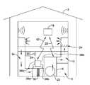
- FIG. 1is a schematic view of a building 2 having an illustrative heating, ventilation, and air conditioning (HVAC) system 4 . While FIG. 1 shows a typical forced air type HVAC system 4 , other types of HVAC systems are contemplated including, but not limited to, boiler systems, radiant heating systems, electric heating systems, cooling systems, heat pump systems, and/or any other suitable type of HVAC system 4 , as desired.
- the illustrative HVAC system 4 of FIG. 1includes one or more HVAC components 6 , a system of ductwork and air vents including a supply air duct 10 and a return air duct 14 , and at least one HVAC controller 18 .
- the one or more HVAC components 6may include, but are not limited to, a furnace, a heat pump, an electric heat pump, a geothermal heat pump, an electric heating unit, an air conditioning unit, a humidifier, a dehumidifier, an air exchanger, an air cleaner, a damper, a valve, and/or the like.
- the HVAC controller(s) 18may be configured to control the comfort level in the building or structure by activating and deactivating the HVAC component(s) 6 in a controlled manner.
- the HVAC controller(s) 18may be configured to control the HVAC component(s) 6 via a wired or wireless communication link 20 .
- the HVAC controller(s)may wirelessly communicate with the one or more HVAC components(s) 6 following a wireless protocol such as, for example, cellular communication, ZigBee, Bluetooth, WiFi, IrDA, dedicated short range communication (DSRC), EnOcean, or any other suitable wireless protocols, as desired.
- the HVAC controller(s) 18may be a thermostat, such as, for example, a wall mountable thermostat, but this is not required in all embodiments.
- a thermostatmay include (e.g. within the thermostat housing) or have access to a temperature sensor for sensing an ambient temperature at or near the thermostat.
- the HVAC controller(s) 18may be a zone controller, or may include multiple zone controllers each monitoring and/or controlling the comfort level within a particular zone in the building or other structure.
- HVAC controllerwhich is not meant to be limiting in any way, is disclosed in: US Published Patent Application No. 20090140062, entitled “HVAC CONTROLLER THAT SELECTIVELY REPLACES OPERATING INFORMATION ON A DISPLAY WITH SYSTEM STATUS INFORMATION”; US Published Application No. 20090143880, entitled “HVAC CONTROLLER WITH CONTEXT SENSITIVE HELP SCREENS”; US Published Application No. 20090143918, entitled “METHOD AND APPARATUS FOR CONFIGURING AN HVAC CONTROLLER”; US Published Application No.
- the HVAC component(s) 6may provide heated air (and/or cooled air) via the ductwork throughout the building 2 .
- the HVAC component(s) 6may be in fluid communication with every room and/or zone in the building 2 via the ductwork 10 and 14 , but this is not required.
- an HVAC component 6e.g. forced warm air furnace
- the heated airmay be forced through supply air duct 10 by a blower or fan 22 .
- the cooler air from each zonemay be returned to the HVAC component 6 (e.g. forced warm air furnace) for heating via return air ducts 14 .
- an HVAC component 6e.g. air conditioning unit
- the cooled airmay be forced through supply air duct 10 by the blower or fan 22 .
- the warmer air from each zonemay be returned to the HVAC component 6 (e.g. air conditioning unit) for cooling via return air ducts 14 .
- the HVAC system 4may include an optional communications gateway or other device 23 that may allow one or more of the HVAC components 6 , as described herein, to communicate wirelessly with one another in accordance with a wireless communications protocol such as, for example, cellular communication, ZigBee, Bluetooth, WiFi, IrDA, dedicated short range communication (DSRC), EnOcean, or any other suitable wireless protocols, as desired.
- a wireless communications protocolsuch as, for example, cellular communication, ZigBee, Bluetooth, WiFi, IrDA, dedicated short range communication (DSRC), EnOcean, or any other suitable wireless protocols, as desired.
- the communications gateway 23may facilitate communication between the various HVAC components 6 over a local area network (LAN), a wide area network (WAN), or the internet. These are just some examples.
- the system of vents or ductwork 10 and/or 14can include one or more dampers 24 to regulate the flow of air, but this is not required.
- one or more dampers 24may be coupled to one or more HVAC controller(s) 18 , and can be coordinated with the operation of one or more HVAC components 6 .
- the one or more HVAC controller(s) 18may actuate dampers 24 to an open position, a closed position, and/or a partially open position to modulate the flow of air from the one or more HVAC components 6 to an appropriate room and/or zone in the building or other structure.
- the dampers 24may be particularly useful in zoned HVAC systems, and may be used to control which zone(s) receives conditioned air from the HVAC component(s) 6 .
- one or more air filters 30may be used to remove dust and other pollutants from the air inside the building 2 .
- the air filter(s) 30is installed in the return air duct 14 , and may filter the air prior to the air entering the HVAC component 6 , but it is contemplated that any other suitable location for the air filter(s) 30 may be used.
- the presence of the air filter(s) 30may not only improve the indoor air quality, but may also protect the HVAC components 6 from dust and other particulate matter that would otherwise be permitted to enter the HVAC component 6 .
- the illustrative HVAC system 4may include an equipment interface module (EIM) 34 .
- the equipment interface module 34may be configured to measure or detect a change in a given parameter between the return air side and the discharge air side of the HVAC system 4 .
- the equipment interface module 34may be adapted to measure a difference in temperature, flow rate, pressure, or a combination of any one of these parameters between the return air side and the discharge air side of the HVAC system 4 .
- the equipment interface module 34may be adapted to measure the difference or change in temperature (delta T) between a return air side and discharge air side of the HVAC system 4 for the heating and/or cooling mode.
- the equipment interface module 34may be configured to communicate with the HVAC controller 18 via, for example, a wired or wireless communication link 42 .
- the equipment interface module 34may be incorporated or combined with the HVAC controller 18 .
- the equipment interface module 34may communicate, relay or otherwise transmit data regarding the selected parameter (e.g. temperature, pressure, flow rate, etc.) to the HVAC controller 18 .
- the HVAC controller 18may use the data from the equipment interface module 34 to evaluate the system's operation and/or performance.
- the HVAC controller 18may compare data related to the difference in temperature (delta T) between the return air side and the discharge air side of the HVAC system 4 to a previously determined delta T limit stored in the HVAC controller 18 to determine a current operating performance of the HVAC system 4 .
- delta Tdifference in temperature
- the equipment interface module 34may include a first temperature sensor 38 a located in the return (incoming) air duct 14 , and a second temperature sensor 38 b located in the discharge (outgoing or supply) air duct 10 .
- the equipment interface module 34may include a differential pressure sensor including a first pressure tap 39 a located in the return (incoming) air duct 14 , and a second pressure tap 39 b located downstream of the air filter 30 to measure a change in a parameter related to the amount of flow restriction through the air filter 30 .
- the equipment interface module 34when provided, may include at least one flow sensor that is capable of providing a measure that is related to the amount of air flow restriction through the air filter 30 .
- the equipment interface module 34may include an air filter monitor. These are just some examples.
- FIG. 2is a schematic view of an illustrative HVAC controller 18 .
- HVAC controller 18may be a thermostat and may include a temperature and/or humidity sensor, but this is not required.
- HVAC controller 18includes a controller (e.g. microprocessor, microcontroller, etc.) 44 , a temperature sensor and/or humidity sensor 46 , a user interface 48 , and a memory 52 .
- the HVAC controller 18may include an input/output block (I/O block) 58 for receiving one or more signals from the HVAC system and/or for providing one or more control signals to the HVAC system.
- the I/O block 58may communicate with one or more HVAC components 6 of the HVAC system 4 .
- the I/O block 58may communicate with another controller, which is in communication with one or more HVAC components 6 of the HVAC system 4 , such as a zone panel in a zoned HVAC system.
- the I/O block 58may also be configured to wirelessly communicate with one or more wireless devices.
- the controller 44may be coupled to the user interface 48 , the memory 52 , the temperature sensor 46 , and the I/O block 58 .
- the controller 44 of the illustrative HVAC controller 18may operate in accordance with an algorithm that controls or at least partially controls one or more HVAC components 6 of an HVAC system such as, for example, HVAC system 4 shown in FIG. 1 .
- the controller 44may, for example, operate in accordance with an algorithm that provides temperature set points, starting and/or ending times, and the like.
- HVAC controller 18may include a timer (not shown). The timer may be integral to the controller 44 or may be provided as a separate component.
- the user interface 48may be any suitable user interface that permits HVAC controller 18 to display and/or solicit information, as well as accept one or more user interactions with the HVAC controller 18 .
- the user interface 48may permit a user to enter data such as temperature set points, humidity set points, starting times, ending times, diagnostic limits, conditions under which diagnostic limits may be suspended, responses to alerts, and the like.
- the user interface 48may include a display and a distinct keypad.
- a displaymay be any suitable display.
- a displaymay include or may be a liquid crystal display (LCD), and in some cases a fixed segment display or a dot matrix LCD display.
- user interface 48may be a touch screen LCD panel that functions as both display and keypad.
- a touch screen LCD panelmay be adapted to solicit values for a number of operating parameters and/or to receive such values, but this is not required.
- the memory 52 of the illustrative HVAC controller 18may be in communication with the controller 44 .
- Memory 52may be used to store any desired information, such as the aforementioned control algorithm, set points, schedule times, diagnostic limits such as, for example, differential pressure limits, delta T limits, and the like.
- Memory 52may be any suitable type of storage device including, but not limited to, RAM, ROM, EPROM, flash memory, a hard drive, and/or the like.
- controller 44may store information within memory 52 , and may subsequently retrieve the stored information.
- HVAC controller 18may include a data port 56 .
- Data port 56may be a wireless port such as a BluetoothTM port or any other wireless protocol.
- data port 56may be a wired port such as a serial port, a parallel port, a CATS port, a USB (universal serial bus) port, and/or the like.
- data port 56may be a USB port and may be used to download and/or upload information from a USB flash drive or some other data source. Other remote devices may also be employed, as desired.
- Data port 56may be configured to communicate with controller 44 and may, if desired, be used to upload information to controller 44 and/or download information from controller 44 .
- Information that can be uploaded and/or downloadedmay include, for example, values of operating parameters.
- data port 56may be used to upload a previously-created thermostat configuration into HVAC controller 18 , thereby hastening the programming process.
- data port 56may be used to download a thermostat configuration that has been created using HVAC controller 18 , so that the thermostat configuration may be transferred to other similar thermostats, hastening their programming process.
- data port 56may be used to upload and/or download information pertaining to an HVAC dealer or contractor, if desired.
- data port 56may be used to download data stored within the memory 52 for analysis.
- data port 56may be used to download a faults and/or alerts log or parts thereof to a remote device such as a USB memory stick (also sometimes referred to as a thumb drive or jump drive), personal computer, laptop, iPAD® or other tablet computer, PDA, smart phone, or other remote device, as desired.
- a remote devicesuch as a USB memory stick (also sometimes referred to as a thumb drive or jump drive), personal computer, laptop, iPAD® or other tablet computer, PDA, smart phone, or other remote device, as desired.
- the datamay be convertible to an MS EXCEL®, MS WORD®, text, XNL, and/or Adobe PDF® file, but this is certainly not required.
- FIG. 3is a front view of an illustrative HVAC controller 18 .
- HVAC controller 18may be configured to provide substantial display and/or programming functionality.
- HVAC controller 18may include a display 62 that is disposed within a housing 66 but viewable externally from the housing 66 .
- display 62may be a touch screen LCD display.
- display 62may be a dot matrix touch screen LCD display.
- a dot matrix touch screen LCD displayis a touch screen LCD that permits images such as letters, numbers, graphics, images, and the like to be displayed anywhere on the LCD, rather than being confined to predetermined locations such as is the case with a fixed segment type of LCD display.
- Housing 66may be formed of any suitable material, such as a polymeric material. In some cases, the housing 66 may be formed such that it defines a data port 56 (see FIG. 2 ). The housing 66 may also include suitable wiring and/or other electrical connections 68 such that the HVAC controller 18 may be electrically coupled to the HVAC system 4 .
- the HVAC system 4may also include one or more wireless devices that may be configured to communicate and/or interact via a wireless communication link (e.g. I/O block 58 ) with the HVAC controller 18 .
- exemplary wireless devicesthat may be incorporated into the HVAC system 4 include, but are not limited to, temperature sensors, humidity sensors, gas sensors, an equipment interface module, another thermostat, a zone control panel, a damper, a valve, and/or any other suitable wireless sensor or device.
- the one or more wireless devicesmay operate on battery power.
- the one or more wireless devicesmay have a wired auxiliary source of back-up power in the event of battery failure.
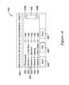
- FIG. 4is a schematic view of a portion of the HVAC system 4 including an HVAC controller 18 and a number of wireless devices 240 , 242 , 244 , 246 , 248 , and 250 in communication with the HVAC controller 18 .
- the one or more wireless devices 240 , 242 , 244 , 246 , 248 , and 250may include, but are not limited to, an indoor air temperature sensor 240 , an outdoor air temperature sensor 242 , an indoor humidity sensor 244 , an outdoor humidity sensor 246 , a remote control unit 248 , a wireless adapter 520 , and/or any other suitable wireless device or sensor.
- the HVAC system 4may include indoor air temperature sensors 240 located at different locations throughout the building or structure 2 .
- the HVAC system 4may include a wireless indoor air temperature sensor 40 mounted to a wall of the building or structure at a location that is remote from the HVAC controller(s) 18 .
- the HVAC system 4may also include an outdoor temperature sensor 242 and/or an outdoor humidity sensor 246 installed at a location external to the building or structure 2 .
- a remote control unit 248may be provided for communicating with and/or controlling the one or more wireless devices and/or HVAC controller 18 , if desired.
- the one or more wireless devices 240 , 242 , 244 , 246 , 428 , and/or 250may be configured to send commands to the HVAC controller 18 via a one-way, wireless communication link. In other cases, the one or more wireless devices 240 , 242 , 244 , 246 , 428 , and/or 250 may be configured to send and/or receive commands to and from the HVAC controller 18 via a two-way, wireless communication link.
- the communication link established between the one or more wireless devices 240 , 242 , 244 , 246 , 428 , and/or 250 and the one or more HVAC controllers 18may be a direct communication link, or alternatively, an indirect communication link where communication between the control unit and the one or more HVAC controllers 18 is routed through a communications device such as, for example, communications gateway 23 as shown in FIG. 1 .
- the one or more wireless devices 240 , 242 , 244 , 246 , 428 , and/or 250may be installed at the same time as the HVAC controller(s) 18 (e.g. new installation). In other instances, the one or more wireless devices 240 , 242 , 244 , 246 , 428 , and/or 250 may be installed in a building or structure that already has an existing HVAC controller(s) 18 (e.g. post-installation).
- a communication linkmay need to be established between the one or more wireless devices 240 , 242 , 244 , 246 , 428 , and/or 250 and the HVAC controller(s) 18 so that the HVAC controller(s) 18 may send and/or receive data and/or commands to and/or from the wireless devices.
- a communication link between the wireless sensor 240 and the HVAC controller 18may be established by selecting a connect button 252 provided on the wireless sensor 240 . Selection of the connect button 252 may cause the wireless sensor 240 to send a signal to the existing HVAC controller 18 , commanding the HVAC controller 18 to recognize and enroll the wireless sensor 240 as part of the HVAC system 4 , and establish a communication link between the wireless sensor 240 and the HVAC controller 18 .
- the connect button 252 on the wireless device 240is activated and the wireless device 240 is enrolled with the HVAC controller 18 , the newly enrolled wireless device 240 may be identified on the display 62 of the HVAC controller 18 . This feature may provide visual confirmation to the installer that the wireless device (e.g. wireless sensor 240 ) has been successfully enrolled with the HVAC controller 18 .
- the HVAC controllermay display one or more screens on the display 62 of the user interface 48 that may guide a user through establishing a communication link between the HVAC controller 18 and the one or more wireless devices.
- the communication linkmay be a one-way or a two-way communication link.
- FIGS. 5-12show several illustrative screens that may be displayed on the display 62 of an exemplary HVAC controller 18 during set-up of the HVAC controller 18 with one or more wireless devices such as, for example, wireless indoor air sensor 240 .
- the HVAC controller 18may display a user query screen 120 , as shown in FIG. 5 , that queries the user about any wireless devices such as, for example, wireless sensor 240 that may need to be connected to the HVAC controller 18 as a part of the controller set-up process.
- User query screen 120may include one or more options for responding to the user query presented on the user query screen 120 .
- user query screen 120may include a first option 124 labeled “Yes” and second option 126 labeled “No.” Selection of the first option 124 labeled “Yes” may cause the HVAC controller 18 to subsequently display a connection prompt screen 130 , as shown in FIG. 6 , which may prompt the user to take a certain action to facilitate connection of a selected wireless device (e.g. wireless sensor 240 ) with the HVAC controller 18 .
- a connection prompt screen 130as shown in FIG. 6
- connection prompt screen 130may include a first user message 134 that instructs to the user to press and release a connect button (e.g. connect button 252 shown in FIG. 4 ) of the wireless device (e.g. wireless sensor 240 ). Additional information that may be useful to the user may be optionally included within the first user message 134 .
- connection prompt screen 130may also include a status bar 138 that may display the amount of time that has lapsed since connection between the HVAC controller 18 and the wireless device (e.g. wireless sensor 240 ) was attempted but, this is not required. Upon successful connection of the HVAC controller 18 with the wireless device (e.g.
- the HVAC controller 18may display a second user message 140 on the connection prompt screen 130 indicating that a new device has been enrolled and added.
- the second user message 140may be displayed on another subsequent screen or a pop-up screen, but this is not required.
- selection of the button 144 labeled “Done” or “Finished”may cause the HVAC controller 18 to display additional screens related to setting up the HVAC controller 18 , but this is not required.
- selection of the “Done” button 144may cause the HVAC controller 18 to display a home screen such as shown in FIG. 13 , discussed in greater detail below. It will be understood that a similar set of screens may be displayed for any wired accessories needing connection to the HVAC controller 18 , if desired.
- the HVAC controller 18may display a first user prompt screen 150 that may prompt the user to name the wireless device that was just connected (see FIG. 7 ).
- screen 150may include a user message 154 which may prompt the user to name the wireless device.
- Screen 150may also include a keyboard 158 that may be used by the user to enter a name for the device.
- the keyboard 158may be a virtual keyboard.
- the keyboard 158may be a physical keyboard and may include hard buttons to facilitate entry of the device name.
- the device namemay be displayed in a name display region 162 positioned above or below the keyboard 158 .
- the device namemay be displayed in the name display region 162 as the user is entering the name of the device using keyboard 158 .
- Selection of button 166 labeled “ENTER” or “DONE”may cause the HVAC controller 18 to accept the device name entered by the user in name display region 162 , and to assign this name to the wireless device.
- Selection of the “DONE” button 166may also cause the HVAC controller 18 to display a second user prompt screen 170 that may prompt the user to identify the location of the wireless device (see FIG. 8 ).
- screen 170may include a user message 174 which may prompt the user to identify the location of the wireless device.
- Screen 170may also include a keyboard 178 that may be used by the user to enter the location associated with the wireless device.
- the keyboard 178may be a virtual keyboard.
- the keyboard 178may be a physical keyboard including hard buttons.
- the device locationmay be displayed in a location identification region 182 positioned above or below the keyboard 178 .
- the identified locationmay be displayed in the location identification region 182 as the user identifies the location of the wireless device using the keyboard 178 .
- Selection of button 186 labeled “ENTER” or “DONE”may cause the HVAC controller 18 to accept the identified location entered by the user and to associate the location with the wireless device.
- a usermay name a wireless indoor air temperature sensor 40 “Sensor1” and through screen 170 , the user may identify the location of “Sensor1” as the “Living Room.”
- the HVAC controller 18may then store the name of the wireless device and its location in the controller memory.
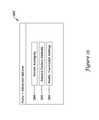
- Selection of button 186may cause the HVAC controller 18 to display a third user prompt screen 190 that may prompt the user to identify a function associated with the connected wireless device (see FIG. 9 ).
- screen 190may include a user prompt 192 that may prompt the user to select a device function.
- screen 190may provide a list of individually selectable device functions 194 for the user's selection. Exemplary device functions include, but are not limited to, temperature control, humidification control, dehumidification control, view only, read only, and none of the above.
- the “View Only” device function 194may be selected in certain cases where, for example, the wireless device is a temperature or a humidity sensor, but its temperature or humidity reading is not to be used to control the operation of the HVAC system 4 .
- Selection indicator boxes 196may be optionally displayed adjacent to each of the individually selectable device functions 194 .
- the selection indicator boxes 196may include a check mark, an “X”, a dot, filled in, or include any other suitable selection indicator as desired.
- more than one device functionmay be associated with a selected wireless device.
- Selection of the button 198 labeled “OK” or “DONE”may cause the HVAC controller 18 accept the selection and associate one or more device functions with the connected wireless device.
- Selection of the “Done” button 198may cause the HVAC controller 18 to display a user query screen 200 , as shown in FIG. 10 , which may query a user about additional devices to be connected.
- User query screen 200may include one or more options for responding to the user query presented on the user query screen 200 .
- user query screen 200may include a first option 204 labeled “Yes” and second option 206 labeled “No”. Selection of the first option 204 labeled “Yes” may cause the HVAC controller 18 to subsequently display screens 130 , 150 , 170 , and 190 as described above with reference to FIGS. 6-9 , which may prompt the user to connect an additional device (screen 130 of FIG.
- the usermay continue the steps outlined with reference to FIGS. 6-10 for connecting wireless devices to the HVAC controller 18 until all of the desired wireless devices are connected.
- the usermay select the second option 206 labeled “No” in response to the user query presented on user query screen 200 of FIG. 10 .
- thismay cause the HVAC controller 18 to display a subsequent user query screen 210 , as shown in FIG. 11 , which may query the user about viewing the connected devices.
- user query screen 210may include a first option 214 labeled “Yes” and a second option 216 labeled “No.” Selection of the second option 216 labeled “No” may cause the HVAC controller 18 to display a home screen such as, for example, home screen 300 shown in FIG. 13 .
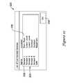
- Selection of the first option 214 labeled “Yes”may cause the HVAC controller 18 to display a subsequent screen 220 , as shown in FIG. 12 , which provides a list 224 of the connected devices, and may include the device name 228 and the device location 230 .
- the list 224may be presented in a table format.
- the tablemay be a scrolling table in which case, the screen 220 may also include a scroll bar or first and second arrows keys (not shown) for navigating the table.
- each device name 228may be individually selectable such that a user may select a device name to view more information about the selected device. For example, a user may select device name “Sensor1” to view the device function by simply touching “Sensor1”.
- the additional information about the selected devicemay be displayed on separate screen, or a “pop-up” screen that may be overlaid on screen 220 .
- the device functionmay be displayed adjacent the device name 228 and the device location 230 .
- the usermay select the button 234 labeled “OK” or “DONE” when they are finished viewing the list of connected devices. Selection of the button 234 labeled “OK” or “DONE” may cause the HVAC controller to display a home screen such as, for example, home screen 300 shown in FIG. 13 .
- Naming and identifying the location of each of the wireless devices connected to the HVAC controller 18may be useful under many circumstances. For example, in some circumstances, it may be useful to identify if the HVAC controller 18 is controlling the system according to temperature and/or humidity levels sensed by the HVAC controller 18 itself and/or according to temperature and/or humidity levels sensed by one or more sensors located at one or more remote locations. This information may be displayed on the display 62 of the HVAC controller 18 . In some cases, the information may be displayed as a brief informational statement on the display 62 adjacent the current temperature and/or humidity level reading.
- the brief information statementmay indicate that the HVAC controller 18 is “sensing from this device,” “sensing from remote location,” “sensing using average sensor value,” “sensing using weighted average sensor value,” and the like. These are just some examples. If sensing from a single location, the informational statement may specify the location.
- At least one of the wireless devicesmay be configured to send a signal indicative of a low battery condition when battery level in the wireless device is low.
- the HVAC controller 18may receive the signal indicative of a low battery condition from the wireless device and, in response, may display an alert on the display 62 of the HVAC controller 18 , indicative of a low battery condition in the wireless device.
- the alert displayed on the display 62 of the HVAC controller 18may identify the name of the wireless device having the low battery condition.
- the alertmay include the device name and/or the device location.
- the wireless devicemay be further configured to activate an alert on the wireless device itself that is indicative of the low battery condition.
- the alert that is activated on the wireless device itselfmay include, for example, a flashing or blinking light such as a light emitting diode (LED), which may be visible to the user.
- the alertmay include an intermittent beep or other audible sound that may indicate to the user that battery level in the wireless device is low.
- At least one of the wireless devicesmay be configured to detect a first low battery condition and to send a first signal indicative of the first low battery condition to the HVAC controller 18 .
- the at least one wireless devicemay be configured to detect a second low battery condition after further battery depletion, and to send a second signal indicative of the second low battery condition to the HVAC controller.
- the wireless devicemay activate an alert on the wireless device itself that is indicative of the second low battery condition.
- the alertmay be a visual or audible alert, as described above.
- the HVAC controller 18may also display an alert on the display 62 of the HVAC Controller 18 .
- the alert displayed on the display 62 of the HVAC controller 18 in response to the second low battery conditionmay be more urgent and/or noticeable than the alert displayed in response to the first low battery condition.
- the wireless devicemay not provide any alert (e.g. flashing light or audible alarm) in response to the first low battery condition, but may provide an alert in response to the second low battery condition.
- FIG. 13provides an example of a home screen 300 that may be displayed by an HVAC controller 18 on its display 62 when no data entry is underway for a period of time, when a user selects a home screen button or, in some cases, after the user has finished adding one or more wireless devices to the HVAC system 4 , as described above with reference to FIGS. 5-10 .
- the illustrative home screen 300 of FIG. 13may include a navigational bar 306 along the top. Navigational bar 306 may be considered as providing top level navigation. In some cases, if desired, navigational bar 306 may include one or more of a HOME button 308 , a FAN button 310 , a SYSTEM button 312 and/or a MENU button 314 .
- the usermay access one or more menus from which the user may make a temperature set point change, a humidity set point change, an indoor air quality change, a programmable schedule change, a system mode change, a fan setting change, an installer set-up change, an exit/entry remote setting change, among others.
- FIG. 14shows an example of a menu screen 320 that may be displayed when a user selects the MENU button 314 on home screen 300 of FIG. 13 .
- the illustrative menu screen 320may include a table 324 that includes one or more individually selectable menu options 328 that may be selected by the user.
- the table 324may be a scrolling table, in which case the menu screen 320 may also include a scroll bar 330 including first and second arrows 332 a , 322 b that may facilitate a user in scrolling through the available menu options 328 .
- a menu option 328 labeled “Advanced Options”may be provided.
- Selection of the menu option 328 labeled “Advanced Options”may cause the HVAC controller 18 to display an Advanced Options menu screen 340 , as shown in FIG. 15 .
- the Advanced Options menu screen 340may list one or more individually selectable installer options available for selection by the user, including an option 344 labeled “Sensor Averaging.”
- Selection of the “Sensor Averaging” option 344may cause the HVAC controller 18 to display a sequence of one or more screens which may allow a user to select which sensors participate in sensor averaging for operation and control of the HVAC system 4 .
- the sensors that may be available for sensor averagingmay include, but are not limited to, any external wired or wireless sensor and the HVAC controller's own internal sensor(s).
- the averaged sensor valuemay be used for temperature control, humidification control, dehumidification control, and/or any other suitable control.
- FIGS. 16A-18show several illustrative screens for selecting one or more sensors to participate in sensor averaging for operation and control of the HVAC system 4 .
- the sensor averagemay be calculated by dividing the sum of the individual sensor values by the number of selected sensors.
- weightsmay be used to weight the sensor values. For example, the sensor value sensed by the sensor in the HVAC controller 18 may be weighted higher than a sensor value sensed by a remotely located sensor.
- FIG. 16Ashows an illustrative screen 350 for selecting which sensor(s) are to be used for temperature control of the HVAC system 4
- FIG. 16Bshows an illustrative screen 600 for assigning a weight to each of the selected sensor(s) if using a weighted sensor average for temperature control
- FIG. 17Ashows an illustrative screen 380 for selecting which sensor(s) are to be used for humidification control
- FIG. 17Bshows an illustrative screen 700 for assigning a weight to each of the selected sensor(s) if using a weighted sensor average for humidification control
- FIG. 18shows an illustrative screen 420 for selecting which sensor(s) are to be used for dehumidification control of the HVAC system.
- all of the available sensorsmay be selected by default for temperature control, humidification control, and/or dehumidification control of the HVAC system 4 , as applicable.
- only the internal sensor(s) of the HVAC controller 18may be selected by default for temperature control, humidification control, and/or dehumidification control of the HVAC system 4 , as applicable.
- the HVAC controller 18may be configured to average the values sensed by the selected sensors and to use the average to control the desired parameter (e.g. temperature, humidification, or dehumidification).
- Sensor selection screen 350may include a user prompt 354 that prompts the user to select which sensor(s) are to be used for temperature control.
- Screen 350may also include a list 358 of the sensors 360 available for selection.
- each of the available sensors 360may be identified by their name and/or their location. In some cases, only the location is used to identify each of the available sensors 360 .
- the sensor name and/or location of each of the available sensors 360may be assigned during connection of the sensors to the HVAC system 4 as described above with reference to FIGS. 5-10 . Additionally, in some cases, only those sensors that have been previously identified as having a temperature control function are included in the list 358 .
- a particular sensorhas not been identified as having a temperature control function; it may not be included in the list 358 .
- the sensorhas been previously identified as “View Only” or “Read Only”, it may not be included in the list 358 of available sensors.
- Each of the available sensors 360 included in list 358may be individually selectable for use in sensor averaging, such that selection of one sensor does not affect selection of another sensor.
- Screen 350may include a scroll bar 366 and/or first and second arrow keys 368 a and 368 b for navigating through the list 358 of sensors available for selection 360 .
- selection indicator boxes 362may be provided adjacent to each of the sensors 360 available for selection included in the list 358 .
- the selection indicator boxes 362may include a check mark, an “X”, a dot, or be filled in to indicate selection. In the example shown, the user may deselect a previous selection by simply touching the selection indicator box 362 . In some cases, all of the sensors will be selected by default in which case, a user may need to deselect those sensors that they do not wish to contribute to the temperature control.
- Sensor selection screen 350may also include a “BACK” button 372 that, when selected, may cause HVAC controller 18 to display the previous screen. Additionally, sensor selection screen 350 may include a button 374 labeled “HELP” that, when selected, may cause HVAC controller 18 to display additional information about the current screen that may be useful to a user. Selection of button 376 labeled “DONE” may cause the HVAC controller 18 to accept the sensor selection(s), and to display a home screen such as home screen 300 of FIG. 13 . Selection of button 378 labeled “NEXT” may cause the HVAC controller 18 to display a sensor averaging screen 600 , as shown in FIG. 16B , for assigning a weight to each sensor used to produce a weighted sensor average, if applicable.
- Sensor averaging screen 600may include a user prompt 604 that prompts the user to assign a weight to each of the sensor(s) previously selected for use in temperature control.
- Screen 600may display a list 608 of those sensor(s) 360 previously selected for use in temperature control through sensor selection screen 350 as shown in FIG. 16A .
- each of the selected sensors 360may be identified by their name and/or their location. In some cases, only the location is used to identify each of the selected sensors 360 .
- a text entry box 612 for assigning a weight to a selected sensor 360may be displayed adjacent to each of the selected sensors 360 displayed in the 608 .
- Screen 600may include first and second arrow keys 616 a and 616 b for navigating through each of the text entry boxes 612 associated with each of the selected sensors 360 . Additionally, screen 600 may include a keyboard 620 that may be used by the user to enter the weight assigned to each of the selected sensors 360 . In some cases, the keyboard 620 may be a virtual keyboard. In other cases, the keyboard 620 may be a physical keyboard including hard buttons. In some cases, each of the sensors 360 displayed in list 608 will be assigned an equal weight by default.
- Sensor selection screen 600may also include a “BACK” button 624 that, when selected, may cause HVAC controller 18 to display the previous screen. Additionally, sensor selection screen 600 may include a button 628 labeled “HELP” that, when selected, may cause HVAC controller 18 to display additional information about the current screen that may be useful to a user. Selection of button 632 labeled “DONE” may cause the HVAC controller 18 to accept the assigned weights, and to display a home screen such as home screen 300 of FIG. 13 . Selection of button 636 labeled “NEXT” may cause the HVAC controller 18 to display another sensor selection screen 380 , as shown in FIG. 17A , for selecting which sensors will be used for humidification control, as applicable.
- Sensor selection screen 380may include a user prompt 384 that prompts the user to select which sensor(s) are to be used for humidification control.
- Screen 380may also include a list 388 of the sensors 390 available for selection.
- Each of the available sensors 390may be identified by their name and/or their location. In some cases, only the location is used to identify each of the available sensors. The sensor name and/or location of each of the available sensors may be assigned during connection of the sensors to the HVAC system 4 , as was described above with reference to FIGS. 5-10 . In some cases, only those sensors 390 that have been previously identified as having a humidification control function are included in the list 388 .
- a particular sensormay not be included in the list 388 .
- Each of the available sensors 390 included in list 388may be individually selectable for use in sensor averaging such that selection of one sensor does not affect selection of another sensor.
- Screen 380may include a scroll bar 396 and/or first and second arrow keys 398 a and 398 b for navigating through the list 388 of sensors available for selection 390 .
- selection indicator boxes 402may be provided adjacent to each of the sensors 390 available for selection included in the list 388 .
- the selection indicator boxes 402may include a check mark, an “X”, a dot, or be filled in to indicate selection.
- the usermay deselect a previous selection by simply touching the selection indicator box 402 .
- all of the sensorswill be selected by default in which case, a user may need to deselect those sensors that they do not wish to contribute to the temperature control.
- Sensor selection screen 380may also include a “BACK” button 404 that, when selected, may cause HVAC controller 18 to display the previous screen. Additionally, sensor selection screen 380 may include a button 408 labeled “HELP” that, when selected, may cause HVAC controller 18 to display additional information about the current screen that may be helpful to a useful to a user. Selection of button 412 labeled “DONE” may cause the HVAC controller 18 to accept the sensor selections and to display a home screen such as home screen 300 of FIG. 13 . Selection of button 416 labeled “NEXT” may cause the HVAC controller 18 to display a sensor averaging screen 700 , as shown in FIG. 17B , for assigning a weight to each of the selected sensors for a weighted sensor average, if applicable.
- Sensor averaging screen 700may include a user prompt 704 that prompts the user to assign a weight to each of the sensor(s) previously selected for use in humidity control.
- Screen 700may display a list 708 of those sensor(s) 390 previously selected for use in humidity control through sensor selection screen 380 as shown in FIG. 17A .
- each of the selected sensors 390may be identified by their name and/or their location. In some cases, only the location is used to identify each of the selected sensors 390 .
- a text entry box 712 for assigning a weight to a selected sensor 390may be displayed adjacent to each of the selected sensors 390 displayed in the 708 .
- Screen 700may include first and second arrow keys 716 a and 716 b for navigating through each of the text entry boxes 712 associated with each of the selected sensors 390 . Additionally, screen 700 may include a keyboard 720 that may be used by the user to enter the weight assigned to each of the selected sensors 390 . In some cases, the keyboard 720 may be a virtual keyboard. In other cases, the keyboard 720 may be a physical keyboard including hard buttons. In some cases, each of the sensors 390 displayed in list 708 will be assigned an equal weight by default.
- Sensor selection screen 700may also include a “BACK” button 724 that, when selected, may cause HVAC controller 18 to display the previous screen. Additionally, sensor selection screen 700 may include a button 728 labeled “HELP” that, when selected, may cause HVAC controller 18 to display additional information about the current screen that may be useful to a user. Selection of button 732 labeled “DONE” may cause the HVAC controller 18 to accept the assigned weights, and to display a home screen such as home screen 300 of FIG. 13 . Selection of button 737 labeled “NEXT” may cause the HVAC controller 18 to display another sensor selection screen 420 , as shown in FIG. 18 , for selecting which sensors will be used for dehumidification control.
- Sensor selection screen 420may include a user prompt 424 that prompts the user to select which sensor(s) are to be used for dehumidification control.
- Sensor selection screen 420may also include a list 428 of the sensors 430 available for selection.
- Each of the available sensors 430may be identified by their name and/or their location. In some cases, only the location is used to identify each of the available sensors 430 .
- the sensor name and/or location of each of the available sensors 430may be assigned during connection of the sensors to the HVAC system 4 , as was described above with reference to FIGS. 5-10 . Additionally, in some cases, only those sensors that have been previously identified as having a dehumidification control function may be included in the list 428 .
- a particular sensorhas not been identified as having a dehumidification control function; it may not be included in the list 358 .
- the sensorhas been previously identified as “View Only” or “Read Only”, it may not be included in the list 428 of available sensors for dehumidification control.
- Each of the available sensors 430 included in list 428may be individually selectable for use in sensor averaging such that selection of one sensor does not affect selection of another sensor.
- Screen 420may include a scroll bar 436 and/or first and second arrow keys 438 aa and 438 b for navigating through the list 428 of sensors available for selection 430 .
- selection indicator boxes 442may be provided adjacent to each of the sensors 430 available for selection included in the list 428 .
- the selection indicator boxes 442may include a check mark, an “X”, a dot, or be filled in to indicate selection. The user may deselect a previous selection by simply touching the selection indicator box 442 .
- none of the available sensors 430may be selected by default in which case, a user may need to select those sensors which the HVAC controller 18 may user for dehumidification control.
- Sensor selection screen 420may also include a “BACK” button 446 that, when selected, may cause HVAC controller 18 to display the previous screen. Additionally, sensor selection screen 420 may also include a button 448 labeled “HELP” that, when selected, may cause HVAC controller 18 to display additional information about the current screen that may be helpful to a useful to a user. Selection of button 452 labeled “DONE” may cause the HVAC controller 18 to accept the sensor selections and to display a home screen such as home screen 300 of FIG. 13 . It will be understood that if multiple sensors are selected for use in dehumidification control, then HVAC controller 18 may display a sensor averaging screen for assigning a weight to each of the selected sensors as discussed above in reference to FIGS. 16B and 17B .
- a usermay view the average sensor readings for temperature, humidification, and/or dehumidification control by, for example, selecting the menu option 328 labeled “View Sensors” provided on menu screen 320 , as shown in FIG. 14 .
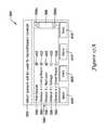
- Selection of the menu option 328 labeled “View Sensors”may cause the HVAC controller 18 to display a sensor data summary screen 460 , as shown in the example provided by FIG. 19 , which may provide a table 464 listing the individual temperature and/or humidity readings for each of the identified sensors.
- Sensor data summary screen 460may include a “BACK” button 468 that, when selected may cause the HVAC controller 18 to display the previous screen.
- Sensor data summary screen 460may also include a “HELP” button 470 that, when selected, may cause the HVAC controller 18 to display additional information about the current screen 460 that may be useful to a user. Additionally, sensor data summary screen 460 may include a “DONE” button 472 , that when selected, may cause the HVAC controller 18 to display menu screen 320 of FIG. 14 or, in some cases, a home screen such as, for example, home screen 300 of FIG. 13 .
- a “View Averages” option 476may also be provided on the sensor data summary screen 460 .
- the “View Averages” option 476when selected, may cause the HVAC controller 18 to display a sensor averages screen 480 a or 480 b as shown in FIGS. 20A and 20B .
- FIG. 20Ashows a sensor averages screen 480 a in which humidification and dehumidification are combined and presented as a single humidity reading.
- FIG. 20Bshows a sensor averages screen 480 b in which values related to humidification and dehumidification are separately displayed. As shown in FIGS.
- the sensor averages screens 480 a , 480 bmay include a first region 484 in which the average temperature and the average humidity (humidification and/or dehumidification, as applicable) are provided.
- Sensor averages screens 480 a , 480 bmay also include a second region 488 that may list the sensors used for temperature control, and that were used to calculate the reported temperature average.
- Sensor averages screens 480 a , 480 bmay also include a third region 492 , which may list the sensors used for humidification control, and which were used to calculate the reported average humidity.
- Sensor averages screen 480 bmay also include a fourth region 496 , which may list the sensors used for dehumidification control, and which were used to calculate the reported average humidity related to dehumidification.
- Sensor averages screens 480 a , 480 bmay also provide a list 498 of those sensors that were identified as “View Only” or “Read Only,” and which were not used for temperature control, humidification control, and/or dehumidification control.
- sensor averages screens 480 a , 480 bmay include a scroll bar 502 including first and second arrow keys 504 a , 504 for navigating through the data on the sensor averages screens 480 , 480 b .
- sensor averages screens 480 a , 480may include a “BACK” button 506 that, when selected, may cause the HVAC controller 18 to display a previous screen.
- Sensor averages screens 480 a , 480 bmay also include a “HELP” button 510 that, when selected, may cause the HVAC controller 18 to display additional information about the current screens that may be useful to a user.
- the “DONE” button 514when selected, may cause the HVAC controller 18 display a previous screen such as, for example, sensor data screen 460 of FIG. 19 or menu screen 320 of FIG. 14 or, in some cases, a home screen such as home screen 300 of FIG. 13 .
Landscapes
- Engineering & Computer Science (AREA)
- Chemical & Material Sciences (AREA)
- Combustion & Propulsion (AREA)
- Mechanical Engineering (AREA)
- General Engineering & Computer Science (AREA)
- Physics & Mathematics (AREA)
- Signal Processing (AREA)
- General Physics & Mathematics (AREA)
- Automation & Control Theory (AREA)
- Fuzzy Systems (AREA)
- Mathematical Physics (AREA)
- Human Computer Interaction (AREA)
- Air Conditioning Control Device (AREA)
Abstract
Description
Claims (20)
Priority Applications (3)
| Application Number | Priority Date | Filing Date | Title |
|---|---|---|---|
| US13/434,778US9488994B2 (en) | 2012-03-29 | 2012-03-29 | Method and system for configuring wireless sensors in an HVAC system |
| US15/340,756US9971364B2 (en) | 2012-03-29 | 2016-11-01 | Method and system for configuring wireless sensors in an HVAC system |
| US15/951,392US10635119B2 (en) | 2012-03-29 | 2018-04-12 | Method and system for configuring wireless sensors in an HVAC system |
Applications Claiming Priority (1)
| Application Number | Priority Date | Filing Date | Title |
|---|---|---|---|
| US13/434,778US9488994B2 (en) | 2012-03-29 | 2012-03-29 | Method and system for configuring wireless sensors in an HVAC system |
Related Child Applications (1)
| Application Number | Title | Priority Date | Filing Date |
|---|---|---|---|
| US15/340,756ContinuationUS9971364B2 (en) | 2012-03-29 | 2016-11-01 | Method and system for configuring wireless sensors in an HVAC system |
Publications (2)
| Publication Number | Publication Date |
|---|---|
| US20130261807A1 US20130261807A1 (en) | 2013-10-03 |
| US9488994B2true US9488994B2 (en) | 2016-11-08 |
Family
ID=49236058
Family Applications (3)
| Application Number | Title | Priority Date | Filing Date |
|---|---|---|---|
| US13/434,778Active2034-07-13US9488994B2 (en) | 2012-03-29 | 2012-03-29 | Method and system for configuring wireless sensors in an HVAC system |
| US15/340,756ActiveUS9971364B2 (en) | 2012-03-29 | 2016-11-01 | Method and system for configuring wireless sensors in an HVAC system |
| US15/951,392Active2032-04-27US10635119B2 (en) | 2012-03-29 | 2018-04-12 | Method and system for configuring wireless sensors in an HVAC system |
Family Applications After (2)
| Application Number | Title | Priority Date | Filing Date |
|---|---|---|---|
| US15/340,756ActiveUS9971364B2 (en) | 2012-03-29 | 2016-11-01 | Method and system for configuring wireless sensors in an HVAC system |
| US15/951,392Active2032-04-27US10635119B2 (en) | 2012-03-29 | 2018-04-12 | Method and system for configuring wireless sensors in an HVAC system |
Country Status (1)
| Country | Link |
|---|---|
| US (3) | US9488994B2 (en) |
Cited By (23)
| Publication number | Priority date | Publication date | Assignee | Title |
|---|---|---|---|---|
| US20150332150A1 (en)* | 2014-05-13 | 2015-11-19 | Carrier Corporation | Method to determine relay wiring required |
| US20150350359A1 (en)* | 2012-09-15 | 2015-12-03 | Honeywell International Inc. | Remote access gateway configurable control system |
| US9922580B2 (en) | 2013-04-30 | 2018-03-20 | Google Llc | Apparatus and method for the virtual demonstration of a smart phone controlled smart home using a website |
| US9971364B2 (en) | 2012-03-29 | 2018-05-15 | Honeywell International Inc. | Method and system for configuring wireless sensors in an HVAC system |
| US9998325B2 (en) | 2012-04-11 | 2018-06-12 | Google Llc | Apparatus and method for seamless commissioning of wireless devices |
| US10018372B2 (en) | 2013-11-22 | 2018-07-10 | Honeywell International Inc. | Method to control a communication rate between a thermostat and a cloud based server |
| US10075334B1 (en)* | 2012-04-11 | 2018-09-11 | Google Llc | Systems and methods for commissioning a smart hub device |
| US10088818B1 (en) | 2013-12-23 | 2018-10-02 | Google Llc | Systems and methods for programming and controlling devices with sensor data and learning |
| US10142122B1 (en)* | 2012-04-11 | 2018-11-27 | Google Llc | User interfaces, systems and methods for configuring smart devices for interoperability with a smart hub device |
| US10262210B2 (en) | 2014-09-30 | 2019-04-16 | Google Llc | Method and system for encrypting network credentials using password provided by remote server to provisioning device |
| US10320442B1 (en) | 2018-02-09 | 2019-06-11 | Ademco Inc. | High bandwidth channel in a frequency hopping system |
| US10397013B1 (en)* | 2012-04-11 | 2019-08-27 | Google Llc | User interfaces, systems and methods for configuring smart devices for interoperability with a smart hub device |
| US10404253B2 (en) | 2013-04-23 | 2019-09-03 | Ademco Inc. | Triac or bypass circuit and MOSFET power steal combination |
| US10429092B2 (en) | 2012-09-15 | 2019-10-01 | Ademco Inc. | Asynchronous reporting system |
| US10514713B2 (en) | 2012-09-15 | 2019-12-24 | Ademco Inc. | Mailbox data storage system |
| US10534383B2 (en) | 2011-12-15 | 2020-01-14 | Ademco Inc. | HVAC controller with performance log |
| US10601604B2 (en) | 2014-11-12 | 2020-03-24 | Google Llc | Data processing systems and methods for smart hub devices |
| US10613555B2 (en) | 2012-07-26 | 2020-04-07 | Ademco Inc. | HVAC controller with wireless network based occupancy detection and control |
| US10928087B2 (en) | 2012-07-26 | 2021-02-23 | Ademco Inc. | Method of associating an HVAC controller with an external web service |
| US10992494B2 (en) | 2012-09-15 | 2021-04-27 | Ademco Inc. | Gateway round-robin system |
| US20210247092A1 (en)* | 2020-02-07 | 2021-08-12 | Venstar, Inc. | Easy control to sensor select for hvac systems |
| US11713895B2 (en) | 2019-01-14 | 2023-08-01 | Research Products Corporation | Multi-zone environmental control system |
| US11796204B2 (en)* | 2019-10-04 | 2023-10-24 | Ademco Inc. | Determining an irregularity in connections for an HVAC controller based on geographic location |
Families Citing this family (55)
| Publication number | Priority date | Publication date | Assignee | Title |
|---|---|---|---|---|
| US8774947B2 (en)* | 2011-03-28 | 2014-07-08 | Emerson Electric Co. | Controller for a climate control system |
| US8892223B2 (en) | 2011-09-07 | 2014-11-18 | Honeywell International Inc. | HVAC controller including user interaction log |
| US10533761B2 (en) | 2011-12-14 | 2020-01-14 | Ademco Inc. | HVAC controller with fault sensitivity |
| US10139843B2 (en) | 2012-02-22 | 2018-11-27 | Honeywell International Inc. | Wireless thermostatic controlled electric heating system |
| US10094585B2 (en)* | 2013-01-25 | 2018-10-09 | Honeywell International Inc. | Auto test for delta T diagnostics in an HVAC system |
| US9806705B2 (en) | 2013-04-23 | 2017-10-31 | Honeywell International Inc. | Active triac triggering circuit |
| US9736616B2 (en)* | 2013-06-21 | 2017-08-15 | Savant Systems, Llc | Configuration connection device |
| US9983244B2 (en) | 2013-06-28 | 2018-05-29 | Honeywell International Inc. | Power transformation system with characterization |
| US10811892B2 (en) | 2013-06-28 | 2020-10-20 | Ademco Inc. | Source management for a power transformation system |
| US11054448B2 (en) | 2013-06-28 | 2021-07-06 | Ademco Inc. | Power transformation self characterization mode |
| EP3651136B1 (en)* | 2013-10-07 | 2022-12-07 | Google LLC | Smart-home hazard detector providing non-alarm status signals at opportune moments |
| JP5804018B2 (en)* | 2013-10-10 | 2015-11-04 | ダイキン工業株式会社 | Air conditioner |
| US9673811B2 (en) | 2013-11-22 | 2017-06-06 | Honeywell International Inc. | Low power consumption AC load switches |
| US9857091B2 (en) | 2013-11-22 | 2018-01-02 | Honeywell International Inc. | Thermostat circuitry to control power usage |
| US20150163945A1 (en) | 2013-12-11 | 2015-06-11 | Honeywell International Inc. | Hvac controller with thermistor biased against an outer housing |
| EP4167376A1 (en)* | 2013-12-17 | 2023-04-19 | Belimo Holding AG | Antenna extension system for an actuator of a heating, ventilation, air conditioning and cooling system |
| TWI580906B (en)* | 2014-05-08 | 2017-05-01 | 台達電子工業股份有限公司 | Controlling device, controlling system and controlling method for indoor apparatus |
| US9628074B2 (en) | 2014-06-19 | 2017-04-18 | Honeywell International Inc. | Bypass switch for in-line power steal |
| US9683749B2 (en) | 2014-07-11 | 2017-06-20 | Honeywell International Inc. | Multiple heatsink cooling system for a line voltage thermostat |
| US10677484B2 (en) | 2015-05-04 | 2020-06-09 | Johnson Controls Technology Company | User control device and multi-function home control system |
| US11216020B2 (en) | 2015-05-04 | 2022-01-04 | Johnson Controls Tyco IP Holdings LLP | Mountable touch thermostat using transparent screen technology |
| AU2016257459B2 (en) | 2015-05-04 | 2019-04-04 | Johnson Controls Technology Company | Multi-function home control system with control system hub and remote sensors |
| US20160370024A1 (en)* | 2015-06-16 | 2016-12-22 | Michael Robledo | Heating and Cooling Control System |
| US10410300B2 (en) | 2015-09-11 | 2019-09-10 | Johnson Controls Technology Company | Thermostat with occupancy detection based on social media event data |
| US10760809B2 (en) | 2015-09-11 | 2020-09-01 | Johnson Controls Technology Company | Thermostat with mode settings for multiple zones |
| US20170082327A1 (en)* | 2015-09-22 | 2017-03-23 | Wael Shahadha Abdulkareem | Solar energy powered air-conditioning and refrigerator system |
| JP6416441B1 (en)* | 2015-10-15 | 2018-10-31 | コーニンクレッカ フィリップス エヌ ヴェKoninklijke Philips N.V. | Air treatment system |
| US10345781B2 (en) | 2015-10-28 | 2019-07-09 | Johnson Controls Technology Company | Multi-function thermostat with health monitoring features |
| US10655881B2 (en) | 2015-10-28 | 2020-05-19 | Johnson Controls Technology Company | Thermostat with halo light system and emergency directions |
| US10546472B2 (en) | 2015-10-28 | 2020-01-28 | Johnson Controls Technology Company | Thermostat with direction handoff features |
| US11277893B2 (en) | 2015-10-28 | 2022-03-15 | Johnson Controls Technology Company | Thermostat with area light system and occupancy sensor |
| US10318266B2 (en) | 2015-11-25 | 2019-06-11 | Johnson Controls Technology Company | Modular multi-function thermostat |
| US11162702B2 (en)* | 2016-04-28 | 2021-11-02 | Trane International Inc. | Method of associating a diagnostic module to HVAC system components |
| US10488062B2 (en) | 2016-07-22 | 2019-11-26 | Ademco Inc. | Geofence plus schedule for a building controller |
| US10941951B2 (en) | 2016-07-27 | 2021-03-09 | Johnson Controls Technology Company | Systems and methods for temperature and humidity control |
| US10104549B2 (en) | 2016-09-30 | 2018-10-16 | Mitsubishi Electric Corporation | Network provisioning system and method for collection of endpoints |
| CN106907770A (en)* | 2017-03-08 | 2017-06-30 | 李世恩 | Based Intelligent Control negative oxygen ion air cleaner |
| US10458669B2 (en) | 2017-03-29 | 2019-10-29 | Johnson Controls Technology Company | Thermostat with interactive installation features |
| WO2018191510A1 (en) | 2017-04-14 | 2018-10-18 | Johnson Controls Technology Company | Multi-function thermostat with air quality display |
| US11162698B2 (en) | 2017-04-14 | 2021-11-02 | Johnson Controls Tyco IP Holdings LLP | Thermostat with exhaust fan control for air quality and humidity control |
| US10015658B1 (en)* | 2017-05-18 | 2018-07-03 | Motorola Solutions, Inc. | Method and apparatus for maintaining mission critical functionality in a portable communication system |
| CN109812929B (en) | 2017-11-20 | 2023-03-28 | 开利公司 | Air conditioning system |
| US11131474B2 (en) | 2018-03-09 | 2021-09-28 | Johnson Controls Tyco IP Holdings LLP | Thermostat with user interface features |
| WO2020039379A1 (en)* | 2018-08-24 | 2020-02-27 | Digitalair Technology (Pty) Ltd | Air quality assessment and treatment in an air conditioner |
| US11236923B2 (en)* | 2018-10-10 | 2022-02-01 | Ademco Inc. | Thermostat with sensor priority screen |
| US11112139B2 (en)* | 2018-12-03 | 2021-09-07 | Ademco Inc. | HVAC controller with a zone commissioning mode |
| US11107390B2 (en) | 2018-12-21 | 2021-08-31 | Johnson Controls Technology Company | Display device with halo |
| US11092346B2 (en)* | 2019-01-08 | 2021-08-17 | Johnson Controls Technology Company | Integrated zone control system |
| US11199338B2 (en)* | 2019-05-24 | 2021-12-14 | Ademco Inc. | Selecting a fallback temperature sensor for no occupancy |
| US11740601B2 (en) | 2019-06-04 | 2023-08-29 | Johnson Controls Tyco IP Holdings LLP | Building management system with universal serial bus (USB) building devices |
| US11713891B2 (en)* | 2019-10-10 | 2023-08-01 | Ademco Inc. | Carbon monoxide detection system |
| US11274844B2 (en)* | 2019-12-05 | 2022-03-15 | Johnson Controls Tyco IP Holdings LLP | Systems and methods for controlling a single-zone climate conditioning system in a multi-zoned manner |
| US20250101949A1 (en)* | 2020-09-07 | 2025-03-27 | Kirk Mills | Plenum resident wind turbine sustainable energy generating system |
| WO2022181658A1 (en)* | 2021-02-26 | 2022-09-01 | パナソニックIpマネジメント株式会社 | Air conditioning system |
| US20220381459A1 (en)* | 2021-06-01 | 2022-12-01 | Broan-Nutone Llc | Air quality management system and control therefor |
Citations (320)
| Publication number | Priority date | Publication date | Assignee | Title |
|---|---|---|---|---|
| US4079366A (en) | 1976-05-20 | 1978-03-14 | Gim Wong | Electronic timer and thermoswitch device |
| US4174807A (en) | 1978-08-10 | 1979-11-20 | Kimble George D | Autocycling control circuit for heating and/or air conditioning systems |
| US4206872A (en) | 1977-03-17 | 1980-06-10 | Levine Michael R | Electronic thermostat |
| US4224615A (en) | 1978-09-14 | 1980-09-23 | Texas Instruments Incorporated | Method of using a liquid crystal display device as a data input device |
| US4264034A (en) | 1979-08-16 | 1981-04-28 | Hyltin Tom M | Digital thermostat |
| US4296334A (en) | 1978-09-07 | 1981-10-20 | Gim Wong | Programmable electronic starting device for autos and the like with means selectable to actuate accessories |
| US4298946A (en) | 1978-12-18 | 1981-11-03 | Texas Instruments Incorporated | Electronically controlled programmable digital thermostat |
| US4308991A (en) | 1980-07-07 | 1982-01-05 | Emerson Electric Co. | Programmable electronic thermostat |
| US4332352A (en) | 1981-01-30 | 1982-06-01 | Honeywell Inc. | Multistage thermostat using integral initiation change means |
| US4337893A (en) | 1980-04-07 | 1982-07-06 | Energy Savings Parhelion | Multi-phase modular comfort controlled heating system |
| US4337822A (en) | 1979-08-16 | 1982-07-06 | Hyltin Tom M | Digital thermostat |
| US4373664A (en) | 1980-01-30 | 1983-02-15 | Robertshaw Controls Company | Wall thermostat and the like |
| US4379483A (en) | 1981-08-17 | 1983-04-12 | The Coleman Company, Inc. | Method of controlling heating and cooling sources |
| US4382544A (en) | 1980-08-08 | 1983-05-10 | J. T. Stewart Associates, Inc. | Energy management system with programmable thermostat |
| US4386649A (en) | 1980-07-15 | 1983-06-07 | Nuclear Systems, Inc. | Programmable thermostatic control device |
| US4388692A (en) | 1980-09-03 | 1983-06-14 | Texas Instruments Incorporated | Electronically controlled programmable digital thermostat having variable threshold hysteresis with time |
| US4431134A (en) | 1982-11-08 | 1984-02-14 | Microcomm Corporation | Digital thermostat with protection against power interruption |
| US4442972A (en) | 1981-09-14 | 1984-04-17 | Texas Instruments Incorporated | Electrically controlled programmable digital thermostat and method for regulating the operation of multistage heating and cooling systems |
| US4446913A (en) | 1983-07-05 | 1984-05-08 | The Trane Company | Auto changeover thermostat with means for handling temperature entry errors |
| US4479604A (en) | 1982-12-30 | 1984-10-30 | Didner Robert S | Zoned control system |
| US4503471A (en) | 1981-10-08 | 1985-03-05 | Sony Corporation | Control arrangement for electronic appliance |
| US4506827A (en) | 1983-10-17 | 1985-03-26 | Johnson Service Company | Battery powered thermostat |
| DE3334117A1 (en) | 1983-09-21 | 1985-04-04 | Siemens Ag | Method for inputting information items for process control with the aid of an input display interacting with an input pen |
| US4556169A (en) | 1984-06-07 | 1985-12-03 | Honeywell Inc. | On-off thermostat based modulating air flow controller |
| US4585164A (en) | 1984-09-24 | 1986-04-29 | Butkovich Joseph J | Portable energy level control system |
| US4606401A (en) | 1985-03-08 | 1986-08-19 | Honeywell, Inc. | Programmable thermostat |
| EP0070414B1 (en) | 1981-07-11 | 1986-10-29 | Robert Bosch Gmbh | Electronic control device for heating plants |
| US4621336A (en) | 1984-09-17 | 1986-11-04 | Emerson Electric Co. | Visual display of time schedule in a programmable thermostat |
| US4622544A (en) | 1985-05-13 | 1986-11-11 | Lifeline Systems, Inc. | Low battery indicator |
| US4628201A (en) | 1983-03-05 | 1986-12-09 | Dr. Johannes Heidenhain Gmbh | Scanning signal balancing circuit |
| US4646964A (en) | 1982-03-26 | 1987-03-03 | Parker Electronics, Inc. | Temperature control system |
| US4717333A (en) | 1983-01-21 | 1988-01-05 | Advanced Mechanical Technology, Inc. | Burner ignition system |
| US4725001A (en) | 1986-10-17 | 1988-02-16 | Arnold D. Berkeley | Electronic thermostat employing adaptive cycling |
| US4837731A (en) | 1987-07-07 | 1989-06-06 | Honeywell Incorporated | System for time programming of states by communicating time data via a continuously rotatable potentiometer |
| US4881686A (en) | 1988-10-13 | 1989-11-21 | Hunter-Melnor, Inc. | Temperature recovery display device for an electronic programmable thermostat |
| US4918439A (en) | 1987-06-23 | 1990-04-17 | Cl 9, Inc. | Remote control device |
| US4942613A (en) | 1988-12-02 | 1990-07-17 | Heil-Quaker Corporation | Service thermostat |
| US4948040A (en) | 1987-06-11 | 1990-08-14 | Mitsubishi Denki Kabushiki Kaisha | Air conditioning system |
| US4969508A (en) | 1990-01-25 | 1990-11-13 | United Enertech Corporation | Wireless thermostat and room environment control system |
| US4992779A (en) | 1988-03-30 | 1991-02-12 | Canon Kabushiki Kaisha | Information input device |
| US4997029A (en) | 1985-12-27 | 1991-03-05 | Mitsubishi Denki Kabushiki Kaisha | Air conditioning apparatus |
| US5005365A (en) | 1988-12-02 | 1991-04-09 | Inter-City Products Corporation (Usa) | Thermostat speed bar graph for variable speed temperature control system |
| US5012973A (en) | 1988-08-26 | 1991-05-07 | Hunter Fan Company | Window air conditioning unit having a built-in programmable thermostat with remote temperature sensor |
| US5036698A (en) | 1990-05-04 | 1991-08-06 | Allied-Signal Inc. | Method and apparatus for predicting life of air filter cartridges |
| US5038851A (en) | 1988-10-13 | 1991-08-13 | Hunter Fan Company | Electronic programmable thermostat for a heating and cooling system with an oscillation control mechanism |
| US5053752A (en) | 1990-02-26 | 1991-10-01 | Jack Epstein | Smoke detector and method using elongated flexible low battery condition indicator member |
| US5065813A (en) | 1988-12-09 | 1991-11-19 | Arnold D. Berkeley | Interactive electronic thermostat with installation assistance |
| US5086385A (en) | 1989-01-31 | 1992-02-04 | Custom Command Systems | Expandable home automation system |
| US5088645A (en) | 1991-06-24 | 1992-02-18 | Ian Bell | Self-programmable temperature control system for a heating and cooling system |
| US5140310A (en) | 1989-11-29 | 1992-08-18 | Motorola, Inc. | Interrupting low battery indicator |
| US5161606A (en) | 1988-12-09 | 1992-11-10 | Arnold D. Berkeley | Interactive electronic thermostat with minimum and maximum temperature thermal limit switches |
| US5170935A (en) | 1991-11-27 | 1992-12-15 | Massachusetts Institute Of Technology | Adaptable control of HVAC systems |
| US5172565A (en) | 1990-05-21 | 1992-12-22 | Honeywell Inc. | Air handling system utilizing direct expansion cooling |
| US5181653A (en) | 1992-03-03 | 1993-01-26 | Foster Glenn D | Residential heating and air conditioning control system |
| US5187797A (en) | 1988-09-28 | 1993-02-16 | Solatrol, Inc. | Machine interface system with hierarchal menus allowing user sequencing and selection of menu items by actuation of three switches |
| US5230482A (en) | 1991-12-20 | 1993-07-27 | Honeywell Inc. | Electronic time thermostat with a temporary next period adjustment means |
| US5238184A (en) | 1991-09-30 | 1993-08-24 | Honeywell Inc. | Thermostat having simple battery level detection |
| US5251813A (en) | 1993-03-25 | 1993-10-12 | Emerson Electric Co. | Indication of low battery voltage condition by altering of temperature setpoint |
| US5259445A (en) | 1992-07-13 | 1993-11-09 | The Detroit Edison Company | Control for dual heating system including a heat pump and furnace |
| US5272477A (en) | 1989-06-20 | 1993-12-21 | Omron Corporation | Remote control card and remote control system |
| US5329991A (en) | 1992-11-05 | 1994-07-19 | Hunter Fan Company | Pre-programmed electronic programmable thermostat |
| US5348078A (en) | 1993-07-08 | 1994-09-20 | Steven D. Dushane | Dwelling heating and air conditioning system |
| US5351035A (en) | 1993-02-22 | 1994-09-27 | Ben A. Everson | Clogged filter indicator |
| US5386577A (en) | 1990-02-23 | 1995-01-31 | Kabushiki Kaisha Toshiba | Display control apparatus capable of changing luminance depending on conditions of power supply circuit |
| US5390206A (en) | 1991-10-01 | 1995-02-14 | American Standard Inc. | Wireless communication system for air distribution system |
| US5404934A (en) | 1992-05-19 | 1995-04-11 | Currise & Carlson, Inc. | Retrofit air conditioning system |
| US5414618A (en) | 1990-07-18 | 1995-05-09 | The Toro Company | Irrigation controller with analog data input devices |
| US5429649A (en) | 1992-04-14 | 1995-07-04 | Robin; Roger C. | Device for the detection of the clogging of an air filter |
| EP0434926B1 (en) | 1989-12-29 | 1995-08-23 | B.P.T. S.p.A. | A programmable thermostat with a temperature display |
| FR2711230B1 (en) | 1993-10-13 | 1995-12-29 | Atlantic Ste Fse Dev T | Heating control method and corresponding programmable device. |
| US5482209A (en) | 1994-06-01 | 1996-01-09 | Honeywell Inc. | Method and means for programming a programmable electronic thermostat |
| US5495887A (en) | 1993-05-21 | 1996-03-05 | Erie Manufacturing (Canada) Co. Limited | Temperature control system and controller therefor |
| US5506572A (en) | 1993-06-23 | 1996-04-09 | Lodgenet Entertainment Corporation | Low battery detection system |
| US5526422A (en) | 1994-06-20 | 1996-06-11 | At&T Corp. | System and method for cleaning the display screen of a touch screen device |
| US5537106A (en) | 1990-08-24 | 1996-07-16 | Sony Corporation | Remote controller |
| US5544036A (en) | 1992-03-25 | 1996-08-06 | Brown, Jr.; Robert J. | Energy management and home automation system |
| US5566879A (en) | 1993-12-06 | 1996-10-22 | Comptel Domotique Inc. | System for centralized controlling of a plurality of temperature regulating devices |
| US5570837A (en) | 1995-10-18 | 1996-11-05 | Emerson Electric Co. | Programmable digital thermostat with means for enabling temporary connection of a battery thereto |
| US5590831A (en) | 1994-10-19 | 1997-01-07 | Whirlpool Corporation | Menu driven remote control for a room air conditioner |
| US5603451A (en) | 1995-03-31 | 1997-02-18 | John W. Helander | Aesthetic thermostat |
| WO1997011448A1 (en) | 1995-09-18 | 1997-03-27 | Intellinet | User interface for home automation system |
| US5654813A (en) | 1995-03-10 | 1997-08-05 | Whitworth; Thomas W. | Infrared receiver and system for controlling a module |
| US5668535A (en) | 1995-12-07 | 1997-09-16 | Emerson Electric Co. | Filter condition sensor and indicator |
| US5671083A (en) | 1995-02-02 | 1997-09-23 | Texas Instruments Incorporated | Spatial light modulator with buried passive charge storage cell array |
| US5673850A (en) | 1996-07-22 | 1997-10-07 | Lux Products Corporation | Programmable thermostat with rotary dial program setting |
| US5679137A (en) | 1995-06-07 | 1997-10-21 | Honeywell Inc. | Optical dirty cell sensor for an electronic air cleaner |
| WO1997039392A1 (en) | 1996-04-17 | 1997-10-23 | Erwin Hanazeder | Device for regulating a heating installation, particularly in a residential building |
| US5682206A (en) | 1995-09-25 | 1997-10-28 | Thomson Consumer Electronics, Inc. | Consumer interface for programming device |
| US5711785A (en) | 1995-10-26 | 1998-01-27 | Ormet Corporation | Method and apparatus for controlling the cleaning cycle of air filter elements and for predicting the useful life thereof |
| US5732691A (en) | 1996-10-30 | 1998-03-31 | Rheem Manufacturing Company | Modulating furnace with two-speed draft inducer |
| US5761083A (en) | 1992-03-25 | 1998-06-02 | Brown, Jr.; Robert J. | Energy management and home automation system |
| US5782296A (en) | 1996-06-14 | 1998-07-21 | Hunter Fan Company | Auto-programmable electronic thermostat |
| US5810908A (en) | 1997-05-02 | 1998-09-22 | Bemis Manufacturing Company | Electronic control for air filtering apparatus |
| US5818428A (en) | 1993-01-21 | 1998-10-06 | Whirlpool Corporation | Appliance control system with configurable interface |
| US5831134A (en)* | 1993-04-20 | 1998-11-03 | Peroxid-Chemie Gmbh | Continuous production process of tertiary alcohols by radical addition of secondary alcohols to alkenes |
| US5833134A (en) | 1995-10-27 | 1998-11-10 | Ho; Tienhou Joseph | Wireless remote temperature sensing thermostat with adjustable register |
| US5839654A (en) | 1996-02-05 | 1998-11-24 | Innova Patent Trust | Portable air comfort system thermostat enabling personal localized control of room temperature |
| US5840094A (en) | 1996-07-31 | 1998-11-24 | Donaldson Company, Inc. | Air filter element; assembly; and, method |
| US5862737A (en) | 1996-04-10 | 1999-01-26 | Honeywell Consumer Products Inc. | Filter change indicator |
| US5873519A (en) | 1997-08-19 | 1999-02-23 | Heatcraft Inc. | Electronic thermostat with multiple program options |
| US5886697A (en) | 1993-05-24 | 1999-03-23 | Sun Microsystems, Inc. | Method and apparatus for improved graphical user interface having anthropomorphic characters |
| US5901183A (en) | 1996-09-25 | 1999-05-04 | Magellan Corporation | Signal correlation technique for a receiver of a spread spectrum signal including a pseudo-random noise code that reduces errors when a multipath signal is present |
| US5902183A (en) | 1996-11-15 | 1999-05-11 | D'souza; Melanius | Process and apparatus for energy conservation in buildings using a computer controlled ventilation system |
| US5909429A (en) | 1996-09-03 | 1999-06-01 | Philips Electronics North America Corporation | Method for installing a wireless network which transmits node addresses directly from a wireless installation device to the nodes without using the wireless network |
| US5917416A (en) | 1997-03-11 | 1999-06-29 | Read; Robert Michael | Easy to install temperature alarm system |
| US5917141A (en) | 1998-01-12 | 1999-06-29 | Naquin, Jr.; Clyde J. | Air filter monitoring device |
| US5915473A (en) | 1997-01-29 | 1999-06-29 | American Standard Inc. | Integrated humidity and temperature controller |
| US5937942A (en) | 1998-03-17 | 1999-08-17 | Hunter Fan Company | Electronic programmable thermostat with temporary reset |
| USD413328S (en) | 1997-05-21 | 1999-08-31 | Sony Corporation | Remote controller combined with wireless telephone |
| US5947372A (en) | 1996-11-01 | 1999-09-07 | Tiernan; Teresa Conaty | Combined fuel level monitor and thermostat |
| US5950709A (en) | 1995-07-21 | 1999-09-14 | Honeywell Inc. | Temperature control with stored multiple configuration programs |
| US6009355A (en) | 1997-01-28 | 1999-12-28 | American Calcar Inc. | Multimedia information and control system for automobiles |
| EP0678204B1 (en) | 1993-01-05 | 2000-03-01 | Honeywell Inc. | Multipurpose user interface |
| US6032867A (en) | 1998-04-21 | 2000-03-07 | Dushane; Steve | Flat plate thermostat and wall mounting method |
| EP0985994A1 (en) | 1998-09-11 | 2000-03-15 | Electrowatt Technology Innovation AG | Method and device for inputting process parameters |
| USD422594S (en) | 1998-05-19 | 2000-04-11 | Alps Electric Co., Ltd. | Data transmitter apparatus |
| US6059195A (en) | 1998-01-23 | 2000-05-09 | Tridelta Industries, Inc. | Integrated appliance control system |
| US6081197A (en) | 1996-04-04 | 2000-06-27 | Garrick; Gilbert Alain Lindsay | Fire detector silenceable low battery pre-alarm |
| US6084523A (en) | 1998-07-13 | 2000-07-04 | The United States Of America As Represented By The Secretary Of The Army | Non-intrusive battery status indicator and inventory system |
| US6101824A (en) | 1997-02-07 | 2000-08-15 | Honeywell Inc. | Flexible thermostat controller that permits various control point profiles when controlling multistage HVAC equipment |
| US6104963A (en) | 1998-04-03 | 2000-08-15 | Johnson Controls Technology Company | Communication system for distributed-object building automation system |
| EP1033641A1 (en) | 1999-03-02 | 2000-09-06 | Danfoss A/S | Control device for a heating system |
| US6119125A (en) | 1998-04-03 | 2000-09-12 | Johnson Controls Technology Company | Software components for a building automation system based on a standard object superclass |
| US6121875A (en) | 1996-02-08 | 2000-09-19 | Inform 2000 | Monitoring and alerting system for buildings |
| US6141595A (en) | 1998-04-03 | 2000-10-31 | Johnson Controls Technology Company | Common object architecture supporting application-centric building automation systems |
| US6140987A (en) | 1996-09-18 | 2000-10-31 | Intellinet, Inc. | User interface for home automation system |
| US6145751A (en) | 1999-01-12 | 2000-11-14 | Siemens Building Technologies, Inc. | Method and apparatus for determining a thermal setpoint in a HVAC system |
| US6149065A (en) | 1998-10-28 | 2000-11-21 | Harper-Wyman Company | Modulating thermostat for gas oven burner |
| US6152375A (en) | 1999-04-22 | 2000-11-28 | Robison; Jerry L. | Remote control thermostat system for controlling electric devices |
| US6154681A (en) | 1998-04-03 | 2000-11-28 | Johnson Controls Technology Company | Asynchronous distributed-object building automation system with support for synchronous object execution |
| WO2000043870A3 (en) | 1999-01-22 | 2000-11-30 | Pointset Corp | Method and apparatus for setting programmable features of an appliance |
| US6167316A (en) | 1998-04-03 | 2000-12-26 | Johnson Controls Technology Co. | Distributed object-oriented building automation system with reliable asynchronous communication |
| US6192282B1 (en) | 1996-10-01 | 2001-02-20 | Intelihome, Inc. | Method and apparatus for improved building automation |
| US6190442B1 (en) | 1999-08-31 | 2001-02-20 | Tishken Products Co. | Air filter gauge |
| US6196467B1 (en) | 1997-02-19 | 2001-03-06 | Dushane Steve | Wireless programming or programmable thermostat mobile unit for multiple separate controller or programmable fixed units and programming transmission method |
| US6208331B1 (en) | 1998-07-01 | 2001-03-27 | Ericsson Inc. | Cleaning touchscreens |
| US6216956B1 (en) | 1997-10-29 | 2001-04-17 | Tocom, Inc. | Environmental condition control and energy management system and method |
| US6236326B1 (en) | 1999-10-29 | 2001-05-22 | Vtech Telecommunications, Ltd. | Method and apparatus for intelligently signaling a battery charge condition in a wireless telephone |
| US6259074B1 (en) | 1999-10-26 | 2001-07-10 | Sims Level 1, Inc. | Apparatus for regulating the temperature of a fluid |
| US6260765B1 (en) | 2000-02-25 | 2001-07-17 | American Secure Care, Llc | Remotely controllable thermostat |
| US6285912B1 (en) | 1996-10-25 | 2001-09-04 | Hubbell Incorporated | System for physically mounting a multifunction user interface to a basic multifunction sensor to access and control various parameters of a control network environment |
| US6290140B1 (en) | 1999-03-04 | 2001-09-18 | Energyiq Systems, Inc. | Energy management system and method |
| US20010025349A1 (en) | 2000-01-07 | 2001-09-27 | Sharood John N. | Retrofit monitoring device |
| USD448757S1 (en) | 2000-06-14 | 2001-10-02 | Nippon Columbia Co., Ltd. | Remote control unit |
| EP1143232A1 (en) | 2000-04-07 | 2001-10-10 | FILTERWERK MANN & HUMMEL GMBH | Monitoring filter insertion |
| US20010029585A1 (en) | 2000-03-13 | 2001-10-11 | Theodore Simon | Integrated security and communications system with secure communications link |
| US6315211B1 (en) | 1999-12-03 | 2001-11-13 | Emerson Electric Co. | Hardwired or battery powered digital thermostat |
| US6318639B1 (en) | 1999-10-15 | 2001-11-20 | Emerson Electric Co. | Thermostat with temporary fan on function |
| US20010042684A1 (en) | 2000-02-04 | 2001-11-22 | Abdeltif Essalik | Gas component sensor for gas oxides |
| US6321637B1 (en) | 1999-12-30 | 2001-11-27 | Honeywell International Inc. | Low-profile air filter module |
| US6330806B1 (en) | 2000-03-03 | 2001-12-18 | York International Corporation | System and method for controlling an HVAC system using a flash mini-card |
| WO2001079952A8 (en) | 2000-03-30 | 2002-01-03 | Univ Delft Tech | Interface unit |
| US20020005435A1 (en) | 2000-07-11 | 2002-01-17 | Invensys Controls Italy Srl | Electronic device for regulating and controlling ambient temperatures, and relative setting method |
| US20020011923A1 (en) | 2000-01-13 | 2002-01-31 | Thalia Products, Inc. | Appliance Communication And Control System And Appliance For Use In Same |
| US6351693B1 (en) | 1999-01-22 | 2002-02-26 | Honeywell International Inc. | Computerized system for controlling thermostats |
| EP1074009B1 (en) | 1998-04-23 | 2002-03-13 | Digital Security Controls Ltd. | Programmable temperature sensor for security system |
| US6385510B1 (en) | 1997-12-03 | 2002-05-07 | Klaus D. Hoog | HVAC remote monitoring system |
| US6394359B1 (en) | 2000-07-12 | 2002-05-28 | Arthur Morgan | Remote control thermostat |
| US6398118B1 (en) | 1999-01-29 | 2002-06-04 | Howard B. Rosen | Thermostat incorporating thin film carbon dioxide sensor and environmental control system |
| WO2002023744A3 (en) | 2000-09-14 | 2002-06-20 | Gen Innovations Llc | System and method for remotely controlling home appliances |
| US20020082746A1 (en) | 2000-12-27 | 2002-06-27 | Honeywell International Inc. | Replaceable media with programmable device |
| US20020096572A1 (en) | 2001-01-22 | 2002-07-25 | Meritor Heavy Vehicle Technology, Llc | Individualized vehicle settings |
| US6449533B1 (en)* | 2000-05-25 | 2002-09-10 | Emerson Electric Co. | Thermostat and method for controlling an HVAC system with remote temperature sensor |
| US6448896B1 (en) | 2001-08-24 | 2002-09-10 | Carrier Corporation | Air filter monitor for HVAC units |
| US6449726B1 (en) | 1999-07-21 | 2002-09-10 | Spotware Technologies, Inc. | Method, system, software, and signal for estimating battery life in a remote control device |
| US6453687B2 (en) | 2000-01-07 | 2002-09-24 | Robertshaw Controls Company | Refrigeration monitor unit |
| US20020138184A1 (en) | 2001-02-05 | 2002-09-26 | The Boeing Company | Diagnostic system and method |
| US6460774B2 (en) | 1999-11-30 | 2002-10-08 | Daikin Industries, Ltd. | Remote controller for air-conditioning apparatus |
| US6466132B1 (en) | 1999-05-14 | 2002-10-15 | International Comfort Products Corporation (Usa) | Incipient failure indication apparatus for an environment control system |
| USD464948S1 (en) | 2001-05-30 | 2002-10-29 | Amx Corporation | Desktop remote controller |
| US6478233B1 (en) | 2000-12-29 | 2002-11-12 | Honeywell International Inc. | Thermal comfort controller having an integral energy savings estimator |
| US20020171624A1 (en) | 2001-05-03 | 2002-11-21 | Mitsubishi Digital Electronics America, Inc. | Control system and user interface for network of input devices |
| US20020173929A1 (en) | 2001-05-15 | 2002-11-21 | Seigel Lawrence J. | Method and system for evaluating the efficiency of an air conditioning apparatus |
| US20030000692A1 (en) | 2000-10-16 | 2003-01-02 | Takashi Okano | Setback timer of air conditioner, air conditioning system, and method of setting setback timer display |
| US6507282B1 (en) | 2000-01-14 | 2003-01-14 | The Holmes Group, Inc. | Filter monitoring system using a thermistor |
| US20030014179A1 (en) | 2001-07-13 | 2003-01-16 | Les Szukala | Engine diagnostic via PDA |
| US6518953B1 (en) | 1997-10-01 | 2003-02-11 | Brad A. Armstrong | Analog controls housed with electronic displays for remote controllers having feedback display screens |
| US6518957B1 (en) | 1999-08-13 | 2003-02-11 | Nokia Mobile Phones Limited | Communications device with touch sensitive screen |
| US20030033156A1 (en) | 2001-08-06 | 2003-02-13 | Mccall John E. | Method and system for providing advisory information to a field service provider |
| US20030033230A1 (en) | 2001-08-06 | 2003-02-13 | Mccall John E. | Method and system for presenting customized advisory information |
| US20030034897A1 (en) | 2001-08-20 | 2003-02-20 | Shamoon Charles G. | Thermostat and remote control apparatus |
| US20030034898A1 (en) | 2001-08-20 | 2003-02-20 | Shamoon Charles G. | Thermostat and remote control system and method |
| US6546419B1 (en) | 1998-05-07 | 2003-04-08 | Richard Humpleman | Method and apparatus for user and device command and control in a network |
| US20030070544A1 (en) | 2001-10-15 | 2003-04-17 | Hamilton Beach/Proctor-Silex, Inc. | System and method for determining filter condition |
| US20030074489A1 (en) | 2001-08-14 | 2003-04-17 | Steger Perry C. | Measurement system with modular measurement modules that convey interface information |
| US6556899B1 (en) | 2000-08-17 | 2003-04-29 | New Flyer Industries | Bus diagnostic and control system and method |
| US20030103075A1 (en) | 2001-12-03 | 2003-06-05 | Rosselot Robert Charles | System and method for control of conference facilities and equipment |
| US6578770B1 (en) | 2002-04-09 | 2003-06-17 | Howard B. Rosen | Thermostat incorporating a carbon dioxide sensor suitable for reading using potentiostat techniques, and environmental control system incorporating such thermostat |
| US6580950B1 (en) | 2000-04-28 | 2003-06-17 | Echelon Corporation | Internet based home communications system |
| US6581846B1 (en) | 2002-03-06 | 2003-06-24 | Howard B. Rosen | Thermostat including a vacation mode in which electrical devices within and proximate the conditioned space are operated by the thermostat to provide an occupied appearance |
| US20030121652A1 (en) | 2003-02-18 | 2003-07-03 | Emerson Electric Co. | Thermostat With One Button Programming Feature |
| US20030123224A1 (en) | 2001-12-13 | 2003-07-03 | Carter Group, Inc. | Electronic controller modules and methods for making and using same |
| US6596059B1 (en) | 2000-09-12 | 2003-07-22 | Skyline Products, Inc. | Automated filter changing device and method |
| US6595430B1 (en) | 2000-10-26 | 2003-07-22 | Honeywell International Inc. | Graphical user interface system for a thermal comfort controller |
| US20030136135A1 (en) | 2000-06-16 | 2003-07-24 | Lg Electronics Inc. | Refrigerator and method for controlling the same |
| US20030142121A1 (en) | 2002-01-30 | 2003-07-31 | Rosen Howard B. | Programmable thermostat system employing a touch screen unit for intuitive interactive interface with a user |
| USD478051S1 (en) | 2002-01-17 | 2003-08-05 | Kabushiki Kaisha Toshiba | Remote controller for household electric/electronic appliances |
| US20030150927A1 (en) | 2002-02-13 | 2003-08-14 | Howard Rosen | Thermostat system with location data |
| US20030150926A1 (en) | 2002-02-13 | 2003-08-14 | Rosen Howard B. | Thermostat system communicating with a remote correspondent for receiving and displaying diverse information |
| US6608560B2 (en) | 2001-06-05 | 2003-08-19 | James D. Abrams | Device and method for providing HVAC service assistance |
| US6621507B1 (en) | 2000-11-03 | 2003-09-16 | Honeywell International Inc. | Multiple language user interface for thermal comfort controller |
| US20030177012A1 (en) | 2002-03-13 | 2003-09-18 | Brett Drennan | Voice activated thermostat |
| US6624750B1 (en)* | 1998-10-06 | 2003-09-23 | Interlogix, Inc. | Wireless home fire and security alarm system |
| US20040074978A1 (en) | 2002-01-30 | 2004-04-22 | Howard Rosen | Programmable thermostat including a feature for providing a running total for the cost of energy consumed during a given period for heating and/or cooling a conditioned space |
| US6726112B1 (en) | 2003-03-07 | 2004-04-27 | Joseph Ho | Illuminating thermostat |
| USD492282S1 (en) | 2002-10-04 | 2004-06-29 | Comau S.P.A. | Device for controlling, programming and/or teaching automatic systems such as robots or the like |
| US20040133314A1 (en) | 2002-03-28 | 2004-07-08 | Ehlers Gregory A. | System and method of controlling an HVAC system |
| US20040193324A1 (en) | 2003-03-24 | 2004-09-30 | Hoog Klaus D. | Device and method for interactive programming of a thermostat |
| US6810307B1 (en) | 2003-11-14 | 2004-10-26 | Honeywell International, Inc. | Thermostat having a temperature stabilized superregenerative RF receiver |
| US6810397B1 (en) | 2000-06-29 | 2004-10-26 | Intel Corporation | Collecting event data and describing events |
| US20040245352A1 (en) | 2003-06-03 | 2004-12-09 | Tim Simon, Inc., A Corporation Of The State Of California | Thermostat with touch-screen display |
| US20040262410A1 (en) | 2003-04-11 | 2004-12-30 | Hull Gerry G. | Graphical thermostat and sensor |
| US6850252B1 (en)* | 1999-10-05 | 2005-02-01 | Steven M. Hoffberg | Intelligent electronic appliance system and method |
| US6868293B1 (en) | 2000-09-28 | 2005-03-15 | Itron, Inc. | System and method for energy usage curtailment |
| US20050083168A1 (en) | 2003-10-17 | 2005-04-21 | Breitenbach John M. | Modular thermostat system |
| USD512208S1 (en) | 2004-05-27 | 2005-12-06 | Asics Corporation | Pair of shoe outsoles |
| US20050270151A1 (en)* | 2003-08-22 | 2005-12-08 | Honeywell International, Inc. | RF interconnected HVAC system and security system |
| US20060032379A1 (en) | 2004-08-11 | 2006-02-16 | Lawrence Kates | Air filter monitoring system |
| US20060071086A1 (en) | 2004-10-06 | 2006-04-06 | Lawrence Kates | System and method for zone heating and cooling |
| USD520989S1 (en) | 2005-07-15 | 2006-05-16 | Thomson Licensing, S.A. | Touch screen remote control |
| US7050026B1 (en) | 2003-05-15 | 2006-05-23 | Howard Rosen | Reverse images in a dot matrix LCD for an environmental control device |
| US7055759B2 (en) | 2003-08-18 | 2006-06-06 | Honeywell International Inc. | PDA configuration of thermostats |
| US20060156392A1 (en)* | 2005-01-07 | 2006-07-13 | Baugher Mark J | System and method for localizing data and devices |
| US7080358B2 (en) | 2002-04-10 | 2006-07-18 | Sun Microsystems, Inc. | Mechanism for generating an execution log and coverage data for a set of computer code |
| US20060168342A1 (en) | 2003-01-15 | 2006-07-27 | Koninklijke Philips Electronics N.V. | Method and arrangement for assigning names to devices in a network |
| US7083109B2 (en) | 2003-08-18 | 2006-08-01 | Honeywell International Inc. | Thermostat having modulated and non-modulated provisions |
| US7083189B2 (en) | 2003-02-13 | 2006-08-01 | Toyoda Gosei Co., Ltd. | Airbag for head protection |
| US7084774B2 (en) | 2003-11-13 | 2006-08-01 | International Business Machines Corporation | Temperature control system |
| US7089088B2 (en) | 2003-01-24 | 2006-08-08 | Tecumseh Products Company | Integrated HVACR control and protection system |
| US20060186213A1 (en) | 2005-02-23 | 2006-08-24 | Carey Steven L | Variable capacity climate control system for multi-zone space |
| US20060196953A1 (en) | 2005-01-19 | 2006-09-07 | Tim Simon, Inc. | Multiple thermostat installation |
| US7108194B1 (en) | 2004-06-01 | 2006-09-19 | Hankins Ii Robert E | Remote controlled thermostat system for the sight-impaired |
| US20060219799A1 (en) | 2005-03-31 | 2006-10-05 | Honeywell International Inc. | Controller system user interface |
| US20060242591A1 (en) | 2005-04-22 | 2006-10-26 | Microsoft Corporation | File dialog user interfaces and creation of same |
| US7130720B2 (en) | 2004-06-23 | 2006-10-31 | Fisher James L | Radio frequency enabled control of environmental zones |
| USD531588S1 (en) | 2006-01-23 | 2006-11-07 | Koninklijke Philips Electronics, N.V. | Remote control unit |
| USD533515S1 (en) | 2005-11-07 | 2006-12-12 | Universal Electronics Inc. | Hand held device body |
| US7156318B1 (en) | 2003-09-03 | 2007-01-02 | Howard Rosen | Programmable thermostat incorporating a liquid crystal display selectively presenting adaptable system menus including changeable interactive virtual buttons |
| US20070013534A1 (en) | 2004-09-16 | 2007-01-18 | Dimaggio Edward G | Detection device for air filter |
| US20070029397A1 (en) | 2005-08-04 | 2007-02-08 | Mueller Carl J | Thermostat with touch screen feature |
| US20070045429A1 (en) | 2005-08-31 | 2007-03-01 | Ranco Incorporated Of Delaware | Time of day zoning climate control system and method |
| US7188002B2 (en) | 2004-01-08 | 2007-03-06 | Maple Chase Company | Appliance diagnostic display apparatus and network incorporating same |
| US7212887B2 (en) | 2004-01-20 | 2007-05-01 | Carrier Corporation | Service and diagnostic tool for HVAC systems |
| USD542236S1 (en) | 2005-11-07 | 2007-05-08 | Sandro David Klein | Hand held device key set |
| US20070114293A1 (en) | 2005-11-18 | 2007-05-24 | Gugenheim Stephen J | Thermostat Adjustment System |
| US20070114295A1 (en) | 2005-11-22 | 2007-05-24 | Robertshaw Controls Company | Wireless thermostat |
| US7225054B2 (en) | 2003-12-02 | 2007-05-29 | Honeywell International Inc. | Controller with programmable service event display mode |
| US7222800B2 (en) | 2003-08-18 | 2007-05-29 | Honeywell International Inc. | Controller customization management system |
| US7231605B1 (en) | 2000-04-07 | 2007-06-12 | Intel Corporation | Method and apparatus for mapping electronic devices coupled to a wireless network |
| US7261762B2 (en) | 2004-05-06 | 2007-08-28 | Carrier Corporation | Technique for detecting and predicting air filter condition |
| US7274973B2 (en) | 2003-12-08 | 2007-09-25 | Invisible Service Technicians, Llc | HVAC/R monitoring apparatus and method |
| US20070277061A1 (en) | 2006-03-07 | 2007-11-29 | Ashe George M | System, Method, Computer Program Product And Article Of Manufacture For Remote Fault Diagnosis And Correction In A Computer System |
| US20070278320A1 (en) | 2003-12-02 | 2007-12-06 | Honeywell International Inc. | Thermostat with electronic image display |
| US20070289731A1 (en) | 2006-05-30 | 2007-12-20 | Energate Inc. | Method for programming and user interface for environmental control |
| US20080015740A1 (en) | 2001-09-10 | 2008-01-17 | Osann Robert Jr | Temperature control system with multiple networked sensors |
| US20080052764A1 (en)* | 2006-08-25 | 2008-02-28 | Huotari Allen J | Apparatus and method for secure configuration of shared medium devices |
| US7341201B2 (en) | 2003-07-08 | 2008-03-11 | Daniel Stanimirovic | Fully articulated and comprehensive air and fluid distribution, metering, and control method and apparatus for primary movers, heat exchangers, and terminal flow devices |
| USRE40437E1 (en) | 2004-11-23 | 2008-07-15 | Howard Rosen | Thermostat system with remote data averaging |
| US7419532B2 (en) | 2004-10-05 | 2008-09-02 | Caterpillar Inc. | Deposition system and method |
| US20080211663A1 (en)* | 1999-11-15 | 2008-09-04 | G.E. Security, Inc. | Power line audio communication system |
| US7435278B2 (en) | 2002-05-06 | 2008-10-14 | Honeywell International Inc. | Deep filter element suitable for replacing a shallow filter element and having a support frame made from thin stock |
| US7451606B2 (en) | 2006-01-06 | 2008-11-18 | Johnson Controls Technology Company | HVAC system analysis tool |
| US7452396B2 (en) | 2006-03-01 | 2008-11-18 | Honeywell International Inc. | Collapsible auto expanding media filter |
| US20090045939A1 (en)* | 2007-07-31 | 2009-02-19 | Johnson Controls Technology Company | Locating devices using wireless communications |
| US7496627B2 (en) | 2006-03-16 | 2009-02-24 | Exceptional Innovation, Llc | Automation control system having digital logging |
| US20090143879A1 (en) | 2007-11-30 | 2009-06-04 | Honeywell International, Inc. | Hvac controller with parameter clustering |
| US20090140057A1 (en)* | 2007-11-30 | 2009-06-04 | Honeywell International, Inc. | Display for hvac systems in remote control units |
| US20090140059A1 (en)* | 2007-11-30 | 2009-06-04 | Honeywell International Inc. | Hvac remote control unit and methods of operation |
| US20090140054A1 (en)* | 2006-05-08 | 2009-06-04 | Giesecke & Devrient Gmbh | Personalisation of portable data supports |
| US20090140060A1 (en) | 2007-11-30 | 2009-06-04 | Honeywell International Inc. | Building control system with remote control unit and methods of operation |
| US20090165644A1 (en) | 2007-12-31 | 2009-07-02 | Campbell David F | Air Filter Apparatus with Self-Contained Detachable Programmable Clogging Indicator |
| US20090199212A1 (en) | 2008-02-04 | 2009-08-06 | Red Hat, Inc. | Configuration interface manager |
| US7594960B2 (en) | 2006-05-26 | 2009-09-29 | 3M Innovative Properties Company | Method and apparatus for monitoring the condition of a flexible filter |
| US7604046B2 (en) | 2003-12-01 | 2009-10-20 | Honeywell International Inc. | Controller interface with multiple day programming |
| US7617691B2 (en) | 2000-03-14 | 2009-11-17 | Hussmann Corporation | Refrigeration system and method of operating the same |
| US7644591B2 (en) | 2001-05-03 | 2010-01-12 | Emerson Retail Services, Inc. | System for remote refrigeration monitoring and diagnostics |
| US20100008422A1 (en) | 2006-10-30 | 2010-01-14 | Nippon Telegraph And Telephone Corporation | Video encoding method and decoding method, apparatuses therefor, programs therefor, and storage media which store the programs |
| US7665019B2 (en) | 2003-09-26 | 2010-02-16 | Nbor Corporation | Method for recording and replaying operations in a computer environment using initial conditions |
| WO2010021700A1 (en) | 2008-08-19 | 2010-02-25 | Thomson Licensing | A propagation map |
| US7676282B2 (en) | 2005-12-02 | 2010-03-09 | International Business Machines Corporation | Compression of servo control logging entries |
| US20100084482A1 (en) | 2007-03-23 | 2010-04-08 | Pro1 Iaq | Thermostat |
| US7707189B2 (en) | 2004-10-05 | 2010-04-27 | Microsoft Corporation | Log management system and method |
| US20100107112A1 (en) | 2008-10-27 | 2010-04-29 | Lennox Industries Inc. | System and method of use for a user interface dashboard of a heating, ventilation and air conditioning network |
| US7713339B2 (en) | 2006-05-26 | 2010-05-11 | 3M Innovative Properties Company | Filter change indicator |
| US7739282B1 (en) | 2001-10-18 | 2010-06-15 | Microsoft Corporation | Method and system for tracking client software use |
| US20100161574A1 (en) | 2008-12-23 | 2010-06-24 | Mark Davidson | Heterogeneous database management system |
| US7768420B2 (en)* | 2004-10-29 | 2010-08-03 | Intel Corporation | Operation and control of wireless appliance networks |
| US20100197238A1 (en) | 2007-10-23 | 2010-08-05 | Qualcomm Incorporated | Fielded Device Failure Tracking and Response |
| US7770242B2 (en) | 2006-07-26 | 2010-08-10 | Sell Timothy L | Collapsible potty |
| US20100204834A1 (en) | 2007-02-13 | 2010-08-12 | Comerford Timothy N | Lifestyle activity choice comfort settings |
| US7793056B2 (en) | 2002-12-23 | 2010-09-07 | Siemens Industry, Inc. | Method of maintaining a data log related to a Programmable Logic Controller (PLC) |
| US20100231361A1 (en)* | 2009-03-13 | 2010-09-16 | Tyco Safety Products Canada Ltd. | System and method for buffered wireless device enrollment in a security system |
| US20100280667A1 (en)* | 2008-07-14 | 2010-11-04 | John Douglas Steinberg | System and method for using a networked electronic device as an occupancy sensor for an energy management system |
| US7865252B2 (en) | 2007-01-26 | 2011-01-04 | Autani Corporation | Upgradeable automation devices, systems, architectures, and methods |
| US20110061527A1 (en) | 2009-09-16 | 2011-03-17 | Challen Sullivan | Direct replacement air filter with automatic filter media advance and wireless communications |
| US20110078515A1 (en) | 2009-09-28 | 2011-03-31 | Canon Kabushiki Kaisha | Information processing apparatus that records logs, and control method and storage medium therefor |
| US20110093424A1 (en) | 2009-10-19 | 2011-04-21 | Siemens Corporation | Heat Flow Model for Building Fault Detection and Diagnosis |
| US7941431B2 (en) | 2002-11-07 | 2011-05-10 | Thomson Reuters Global Resources | Electronic document repository management and access system |
| US7952485B2 (en) | 2008-11-21 | 2011-05-31 | Schechter Tech, Llc | Remote monitoring system |
| US7957775B2 (en) | 2007-11-05 | 2011-06-07 | International Business Machines Corporation | Low battery notification service for wireless device users |
| US7984220B2 (en) | 2004-09-02 | 2011-07-19 | International Business Machines Corporation | Exception tracking |
| US20110185895A1 (en) | 2010-02-03 | 2011-08-04 | Paul Freen | Filter apparatus and method of monitoring filter apparatus |
| US8280556B2 (en) | 2009-12-22 | 2012-10-02 | General Electric Company | Energy management of HVAC system |
| US8304699B2 (en)* | 2008-10-29 | 2012-11-06 | Be Intellectual Property, Inc. | Proximity sensor |
| US20120319851A1 (en) | 2011-06-20 | 2012-12-20 | Honeywell International Inc. | Filter change alert system for an hvac system |
| US20120318137A1 (en) | 2011-06-20 | 2012-12-20 | Honeywell International Inc. | Method and systems for setting an air filter change threshold value in an hvac system |
| US20120323377A1 (en) | 2011-06-20 | 2012-12-20 | Honeywell International Inc. | Methods and systems for monitoring an air filter of an hvac system |
| US20120323375A1 (en) | 2011-06-20 | 2012-12-20 | Honeywell International Inc. | Method and apparatus for configuring a filter change notification of an hvac controller |
| US20120323374A1 (en) | 2011-06-20 | 2012-12-20 | Honeywell International Inc. | Hvac controller with component change notification |
| US20120318073A1 (en) | 2011-06-20 | 2012-12-20 | Honeywell International Inc. | Hvac air filter monitor with sensor compensation |
| US20120318135A1 (en) | 2011-06-20 | 2012-12-20 | Honeywell International Inc. | Methods and systems of verifying a filter change in an hvac system |
| US20120318138A1 (en) | 2011-06-20 | 2012-12-20 | Honeywell International Inc. | Methods and systems for setting an air filter change threshold in an hvac system using a blocking panel |
| US8373553B2 (en)* | 2009-10-27 | 2013-02-12 | Tyco Safety Products Canada Ltd | System and method for automatic enrollment of two-way wireless sensors in a security system |
| US20130060387A1 (en)* | 2009-08-21 | 2013-03-07 | Kevin R. Imes | Proximity detection module on thermostat |
| US20130223279A1 (en)* | 2012-02-24 | 2013-08-29 | Peerapol Tinnakornsrisuphap | Sensor based configuration and control of network devices |
| EP2138919B1 (en) | 2008-06-27 | 2013-12-25 | ABB Research Ltd. | Wireless field device and method to configure same |
| US20140031991A1 (en)* | 2012-07-26 | 2014-01-30 | Honeywell International Inc. | Method of associating an hvac controller with an external web service |
| US8661515B2 (en)* | 2010-05-10 | 2014-02-25 | Intel Corporation | Audible authentication for wireless network enrollment |
| US8677342B1 (en)* | 2008-10-17 | 2014-03-18 | Honeywell International Inc. | System, method and apparatus for replacing wireless devices in a system |
| US9007168B2 (en)* | 2002-10-08 | 2015-04-14 | Gentex Corporation | System and method for enrollment of a remotely controlled device in a trainable transmitter |
Family Cites Families (28)
| Publication number | Priority date | Publication date | Assignee | Title |
|---|---|---|---|---|
| US4316256A (en) | 1979-12-31 | 1982-02-16 | Microcomm Corporation | Thermostat with automatic heat/air conditioning changeover |
| US4598355A (en) | 1983-10-27 | 1986-07-01 | Sundstrand Corporation | Fault tolerant controller |
| US5369597A (en) | 1992-12-21 | 1994-11-29 | Bujak, Jr.; Walter E. | System for controlling heating or cooling capacity in heating or air conditioning systems |
| US5892690A (en)* | 1997-03-10 | 1999-04-06 | Purechoice, Inc. | Environment monitoring system |
| JP3931811B2 (en)* | 2003-01-09 | 2007-06-20 | 株式会社デンソー | Sensor ID registration method for tire pressure monitoring device |
| US20070043478A1 (en) | 2003-07-28 | 2007-02-22 | Ehlers Gregory A | System and method of controlling an HVAC system |
| US6851621B1 (en) | 2003-08-18 | 2005-02-08 | Honeywell International Inc. | PDA diagnosis of thermostats |
| US7789317B2 (en) | 2005-09-14 | 2010-09-07 | Arzel Zoning Technology, Inc. | System and method for heat pump oriented zone control |
| US20090065596A1 (en)* | 2007-05-09 | 2009-03-12 | Johnson Controls Technology Company | Systems and methods for increasing building space comfort using wireless devices |
| US7963454B2 (en)* | 2007-08-27 | 2011-06-21 | Honeywell International Inc. | Remote HVAC control with remote sensor wiring diagram generation |
| EP3121999B1 (en)* | 2008-09-03 | 2019-08-07 | Siemens Industry, Inc. | Method for regulating temperatures in a wireless building management system |
| CN101585389B (en) | 2009-06-15 | 2011-09-28 | 邰举 | Folding scooter |
| US8682937B2 (en)* | 2010-05-08 | 2014-03-25 | Lester F. Ludwig | Energy and internal environment management information systems and methods for buildings and campuses |
| US8510255B2 (en)* | 2010-09-14 | 2013-08-13 | Nest Labs, Inc. | Occupancy pattern detection, estimation and prediction |
| US9092039B2 (en)* | 2010-11-19 | 2015-07-28 | Google Inc. | HVAC controller with user-friendly installation features with wire insertion detection |
| US8892223B2 (en) | 2011-09-07 | 2014-11-18 | Honeywell International Inc. | HVAC controller including user interaction log |
| US9822989B2 (en) | 2011-12-12 | 2017-11-21 | Vigilent Corporation | Controlling air temperatures of HVAC units |
| US10533761B2 (en) | 2011-12-14 | 2020-01-14 | Ademco Inc. | HVAC controller with fault sensitivity |
| US20130158714A1 (en) | 2011-12-14 | 2013-06-20 | Honeywell International Inc. | Hvac controller with user activated performance test |
| US20130158717A1 (en) | 2011-12-14 | 2013-06-20 | Honeywell International Inc. | Hvac controller with delta-t based diagnostics |
| US10747243B2 (en) | 2011-12-14 | 2020-08-18 | Ademco Inc. | HVAC controller with HVAC system failure detection |
| US8902071B2 (en) | 2011-12-14 | 2014-12-02 | Honeywell International Inc. | HVAC controller with HVAC system fault detection |
| US9206993B2 (en) | 2011-12-14 | 2015-12-08 | Honeywell International Inc. | HVAC controller with utility saver switch diagnostic feature |
| US9002523B2 (en) | 2011-12-14 | 2015-04-07 | Honeywell International Inc. | HVAC controller with diagnostic alerts |
| US20130158720A1 (en) | 2011-12-15 | 2013-06-20 | Honeywell International Inc. | Hvac controller with performance log |
| US9442500B2 (en) | 2012-03-08 | 2016-09-13 | Honeywell International Inc. | Systems and methods for associating wireless devices of an HVAC system |
| US10452084B2 (en) | 2012-03-14 | 2019-10-22 | Ademco Inc. | Operation of building control via remote device |
| US9488994B2 (en) | 2012-03-29 | 2016-11-08 | Honeywell International Inc. | Method and system for configuring wireless sensors in an HVAC system |
- 2012
- 2012-03-29USUS13/434,778patent/US9488994B2/enactiveActive
- 2016
- 2016-11-01USUS15/340,756patent/US9971364B2/enactiveActive
- 2018
- 2018-04-12USUS15/951,392patent/US10635119B2/enactiveActive
Patent Citations (365)
| Publication number | Priority date | Publication date | Assignee | Title |
|---|---|---|---|---|
| US4079366A (en) | 1976-05-20 | 1978-03-14 | Gim Wong | Electronic timer and thermoswitch device |
| US4206872A (en) | 1977-03-17 | 1980-06-10 | Levine Michael R | Electronic thermostat |
| US4174807A (en) | 1978-08-10 | 1979-11-20 | Kimble George D | Autocycling control circuit for heating and/or air conditioning systems |
| US4296334A (en) | 1978-09-07 | 1981-10-20 | Gim Wong | Programmable electronic starting device for autos and the like with means selectable to actuate accessories |
| US4224615A (en) | 1978-09-14 | 1980-09-23 | Texas Instruments Incorporated | Method of using a liquid crystal display device as a data input device |
| US4298946A (en) | 1978-12-18 | 1981-11-03 | Texas Instruments Incorporated | Electronically controlled programmable digital thermostat |
| US4337822A (en) | 1979-08-16 | 1982-07-06 | Hyltin Tom M | Digital thermostat |
| US4264034A (en) | 1979-08-16 | 1981-04-28 | Hyltin Tom M | Digital thermostat |
| US4373664A (en) | 1980-01-30 | 1983-02-15 | Robertshaw Controls Company | Wall thermostat and the like |
| US4337893A (en) | 1980-04-07 | 1982-07-06 | Energy Savings Parhelion | Multi-phase modular comfort controlled heating system |
| US4308991A (en) | 1980-07-07 | 1982-01-05 | Emerson Electric Co. | Programmable electronic thermostat |
| US4386649A (en) | 1980-07-15 | 1983-06-07 | Nuclear Systems, Inc. | Programmable thermostatic control device |
| US4382544A (en) | 1980-08-08 | 1983-05-10 | J. T. Stewart Associates, Inc. | Energy management system with programmable thermostat |
| US4388692A (en) | 1980-09-03 | 1983-06-14 | Texas Instruments Incorporated | Electronically controlled programmable digital thermostat having variable threshold hysteresis with time |
| US4332352A (en) | 1981-01-30 | 1982-06-01 | Honeywell Inc. | Multistage thermostat using integral initiation change means |
| EP0070414B1 (en) | 1981-07-11 | 1986-10-29 | Robert Bosch Gmbh | Electronic control device for heating plants |
| US4379483A (en) | 1981-08-17 | 1983-04-12 | The Coleman Company, Inc. | Method of controlling heating and cooling sources |
| US4442972A (en) | 1981-09-14 | 1984-04-17 | Texas Instruments Incorporated | Electrically controlled programmable digital thermostat and method for regulating the operation of multistage heating and cooling systems |
| US4503471A (en) | 1981-10-08 | 1985-03-05 | Sony Corporation | Control arrangement for electronic appliance |
| US4646964A (en) | 1982-03-26 | 1987-03-03 | Parker Electronics, Inc. | Temperature control system |
| US4431134A (en) | 1982-11-08 | 1984-02-14 | Microcomm Corporation | Digital thermostat with protection against power interruption |
| US4479604A (en) | 1982-12-30 | 1984-10-30 | Didner Robert S | Zoned control system |
| US4717333A (en) | 1983-01-21 | 1988-01-05 | Advanced Mechanical Technology, Inc. | Burner ignition system |
| US4628201A (en) | 1983-03-05 | 1986-12-09 | Dr. Johannes Heidenhain Gmbh | Scanning signal balancing circuit |
| US4446913A (en) | 1983-07-05 | 1984-05-08 | The Trane Company | Auto changeover thermostat with means for handling temperature entry errors |
| DE3334117A1 (en) | 1983-09-21 | 1985-04-04 | Siemens Ag | Method for inputting information items for process control with the aid of an input display interacting with an input pen |
| US4506827A (en) | 1983-10-17 | 1985-03-26 | Johnson Service Company | Battery powered thermostat |
| US4556169A (en) | 1984-06-07 | 1985-12-03 | Honeywell Inc. | On-off thermostat based modulating air flow controller |
| US4621336A (en) | 1984-09-17 | 1986-11-04 | Emerson Electric Co. | Visual display of time schedule in a programmable thermostat |
| US4585164A (en) | 1984-09-24 | 1986-04-29 | Butkovich Joseph J | Portable energy level control system |
| US4606401A (en) | 1985-03-08 | 1986-08-19 | Honeywell, Inc. | Programmable thermostat |
| US4622544A (en) | 1985-05-13 | 1986-11-11 | Lifeline Systems, Inc. | Low battery indicator |
| US4997029A (en) | 1985-12-27 | 1991-03-05 | Mitsubishi Denki Kabushiki Kaisha | Air conditioning apparatus |
| US4725001A (en) | 1986-10-17 | 1988-02-16 | Arnold D. Berkeley | Electronic thermostat employing adaptive cycling |
| US4948040A (en) | 1987-06-11 | 1990-08-14 | Mitsubishi Denki Kabushiki Kaisha | Air conditioning system |
| US4918439A (en) | 1987-06-23 | 1990-04-17 | Cl 9, Inc. | Remote control device |
| US4837731A (en) | 1987-07-07 | 1989-06-06 | Honeywell Incorporated | System for time programming of states by communicating time data via a continuously rotatable potentiometer |
| US4992779A (en) | 1988-03-30 | 1991-02-12 | Canon Kabushiki Kaisha | Information input device |
| US5012973A (en) | 1988-08-26 | 1991-05-07 | Hunter Fan Company | Window air conditioning unit having a built-in programmable thermostat with remote temperature sensor |
| US5187797A (en) | 1988-09-28 | 1993-02-16 | Solatrol, Inc. | Machine interface system with hierarchal menus allowing user sequencing and selection of menu items by actuation of three switches |
| US4881686A (en) | 1988-10-13 | 1989-11-21 | Hunter-Melnor, Inc. | Temperature recovery display device for an electronic programmable thermostat |
| US5038851A (en) | 1988-10-13 | 1991-08-13 | Hunter Fan Company | Electronic programmable thermostat for a heating and cooling system with an oscillation control mechanism |
| US5005365A (en) | 1988-12-02 | 1991-04-09 | Inter-City Products Corporation (Usa) | Thermostat speed bar graph for variable speed temperature control system |
| US4942613A (en) | 1988-12-02 | 1990-07-17 | Heil-Quaker Corporation | Service thermostat |
| US5065813A (en) | 1988-12-09 | 1991-11-19 | Arnold D. Berkeley | Interactive electronic thermostat with installation assistance |
| US5161606A (en) | 1988-12-09 | 1992-11-10 | Arnold D. Berkeley | Interactive electronic thermostat with minimum and maximum temperature thermal limit switches |
| US5086385A (en) | 1989-01-31 | 1992-02-04 | Custom Command Systems | Expandable home automation system |
| US5272477A (en) | 1989-06-20 | 1993-12-21 | Omron Corporation | Remote control card and remote control system |
| US5140310A (en) | 1989-11-29 | 1992-08-18 | Motorola, Inc. | Interrupting low battery indicator |
| EP0434926B1 (en) | 1989-12-29 | 1995-08-23 | B.P.T. S.p.A. | A programmable thermostat with a temperature display |
| US4969508A (en) | 1990-01-25 | 1990-11-13 | United Enertech Corporation | Wireless thermostat and room environment control system |
| US5386577A (en) | 1990-02-23 | 1995-01-31 | Kabushiki Kaisha Toshiba | Display control apparatus capable of changing luminance depending on conditions of power supply circuit |
| US5053752A (en) | 1990-02-26 | 1991-10-01 | Jack Epstein | Smoke detector and method using elongated flexible low battery condition indicator member |
| US5036698A (en) | 1990-05-04 | 1991-08-06 | Allied-Signal Inc. | Method and apparatus for predicting life of air filter cartridges |
| US5172565A (en) | 1990-05-21 | 1992-12-22 | Honeywell Inc. | Air handling system utilizing direct expansion cooling |
| US5414618A (en) | 1990-07-18 | 1995-05-09 | The Toro Company | Irrigation controller with analog data input devices |
| US5537106A (en) | 1990-08-24 | 1996-07-16 | Sony Corporation | Remote controller |
| US5088645A (en) | 1991-06-24 | 1992-02-18 | Ian Bell | Self-programmable temperature control system for a heating and cooling system |
| US5238184A (en) | 1991-09-30 | 1993-08-24 | Honeywell Inc. | Thermostat having simple battery level detection |
| US5390206A (en) | 1991-10-01 | 1995-02-14 | American Standard Inc. | Wireless communication system for air distribution system |
| US5170935A (en) | 1991-11-27 | 1992-12-15 | Massachusetts Institute Of Technology | Adaptable control of HVAC systems |
| US5230482A (en) | 1991-12-20 | 1993-07-27 | Honeywell Inc. | Electronic time thermostat with a temporary next period adjustment means |
| US5181653A (en) | 1992-03-03 | 1993-01-26 | Foster Glenn D | Residential heating and air conditioning control system |
| US5761083A (en) | 1992-03-25 | 1998-06-02 | Brown, Jr.; Robert J. | Energy management and home automation system |
| US5544036A (en) | 1992-03-25 | 1996-08-06 | Brown, Jr.; Robert J. | Energy management and home automation system |
| US5429649A (en) | 1992-04-14 | 1995-07-04 | Robin; Roger C. | Device for the detection of the clogging of an air filter |
| US5404934A (en) | 1992-05-19 | 1995-04-11 | Currise & Carlson, Inc. | Retrofit air conditioning system |
| US5259445A (en) | 1992-07-13 | 1993-11-09 | The Detroit Edison Company | Control for dual heating system including a heat pump and furnace |
| US5329991A (en) | 1992-11-05 | 1994-07-19 | Hunter Fan Company | Pre-programmed electronic programmable thermostat |
| EP0678204B1 (en) | 1993-01-05 | 2000-03-01 | Honeywell Inc. | Multipurpose user interface |
| US5818428A (en) | 1993-01-21 | 1998-10-06 | Whirlpool Corporation | Appliance control system with configurable interface |
| US5351035A (en) | 1993-02-22 | 1994-09-27 | Ben A. Everson | Clogged filter indicator |
| US5251813A (en) | 1993-03-25 | 1993-10-12 | Emerson Electric Co. | Indication of low battery voltage condition by altering of temperature setpoint |
| US5831134A (en)* | 1993-04-20 | 1998-11-03 | Peroxid-Chemie Gmbh | Continuous production process of tertiary alcohols by radical addition of secondary alcohols to alkenes |
| US5495887A (en) | 1993-05-21 | 1996-03-05 | Erie Manufacturing (Canada) Co. Limited | Temperature control system and controller therefor |
| US20020060701A1 (en) | 1993-05-24 | 2002-05-23 | Sun Microsystems, Inc. | Graphical user interface for displaying and navigating in a directed graph structure |
| US7240289B2 (en) | 1993-05-24 | 2007-07-03 | Sun Microsystems, Inc. | Graphical user interface for displaying and navigating in a directed graph structure |
| US6020881A (en) | 1993-05-24 | 2000-02-01 | Sun Microsystems | Graphical user interface with method and apparatus for interfacing to remote devices |
| US5886697A (en) | 1993-05-24 | 1999-03-23 | Sun Microsystems, Inc. | Method and apparatus for improved graphical user interface having anthropomorphic characters |
| US6344861B1 (en) | 1993-05-24 | 2002-02-05 | Sun Microsystems, Inc. | Graphical user interface for displaying and manipulating objects |
| US5506572A (en) | 1993-06-23 | 1996-04-09 | Lodgenet Entertainment Corporation | Low battery detection system |
| US5348078A (en) | 1993-07-08 | 1994-09-20 | Steven D. Dushane | Dwelling heating and air conditioning system |
| FR2711230B1 (en) | 1993-10-13 | 1995-12-29 | Atlantic Ste Fse Dev T | Heating control method and corresponding programmable device. |
| US5566879A (en) | 1993-12-06 | 1996-10-22 | Comptel Domotique Inc. | System for centralized controlling of a plurality of temperature regulating devices |
| US5482209A (en) | 1994-06-01 | 1996-01-09 | Honeywell Inc. | Method and means for programming a programmable electronic thermostat |
| US5526422A (en) | 1994-06-20 | 1996-06-11 | At&T Corp. | System and method for cleaning the display screen of a touch screen device |
| US5590831A (en) | 1994-10-19 | 1997-01-07 | Whirlpool Corporation | Menu driven remote control for a room air conditioner |
| US5671083A (en) | 1995-02-02 | 1997-09-23 | Texas Instruments Incorporated | Spatial light modulator with buried passive charge storage cell array |
| US5654813A (en) | 1995-03-10 | 1997-08-05 | Whitworth; Thomas W. | Infrared receiver and system for controlling a module |
| US5603451A (en) | 1995-03-31 | 1997-02-18 | John W. Helander | Aesthetic thermostat |
| US5679137A (en) | 1995-06-07 | 1997-10-21 | Honeywell Inc. | Optical dirty cell sensor for an electronic air cleaner |
| US5950709A (en) | 1995-07-21 | 1999-09-14 | Honeywell Inc. | Temperature control with stored multiple configuration programs |
| WO1997011448A1 (en) | 1995-09-18 | 1997-03-27 | Intellinet | User interface for home automation system |
| US5682206A (en) | 1995-09-25 | 1997-10-28 | Thomson Consumer Electronics, Inc. | Consumer interface for programming device |
| US5570837A (en) | 1995-10-18 | 1996-11-05 | Emerson Electric Co. | Programmable digital thermostat with means for enabling temporary connection of a battery thereto |
| US5711785A (en) | 1995-10-26 | 1998-01-27 | Ormet Corporation | Method and apparatus for controlling the cleaning cycle of air filter elements and for predicting the useful life thereof |
| US5833134A (en) | 1995-10-27 | 1998-11-10 | Ho; Tienhou Joseph | Wireless remote temperature sensing thermostat with adjustable register |
| US5668535A (en) | 1995-12-07 | 1997-09-16 | Emerson Electric Co. | Filter condition sensor and indicator |
| US5839654A (en) | 1996-02-05 | 1998-11-24 | Innova Patent Trust | Portable air comfort system thermostat enabling personal localized control of room temperature |
| US6121875A (en) | 1996-02-08 | 2000-09-19 | Inform 2000 | Monitoring and alerting system for buildings |
| US6081197A (en) | 1996-04-04 | 2000-06-27 | Garrick; Gilbert Alain Lindsay | Fire detector silenceable low battery pre-alarm |
| US5862737A (en) | 1996-04-10 | 1999-01-26 | Honeywell Consumer Products Inc. | Filter change indicator |
| US6013121A (en) | 1996-04-10 | 2000-01-11 | Honeywell Consumer Products, Inc. | Filter change indicator |
| WO1997039392A1 (en) | 1996-04-17 | 1997-10-23 | Erwin Hanazeder | Device for regulating a heating installation, particularly in a residential building |
| US5782296A (en) | 1996-06-14 | 1998-07-21 | Hunter Fan Company | Auto-programmable electronic thermostat |
| US5673850A (en) | 1996-07-22 | 1997-10-07 | Lux Products Corporation | Programmable thermostat with rotary dial program setting |
| US5840094A (en) | 1996-07-31 | 1998-11-24 | Donaldson Company, Inc. | Air filter element; assembly; and, method |
| US5909429A (en) | 1996-09-03 | 1999-06-01 | Philips Electronics North America Corporation | Method for installing a wireless network which transmits node addresses directly from a wireless installation device to the nodes without using the wireless network |
| US6140987A (en) | 1996-09-18 | 2000-10-31 | Intellinet, Inc. | User interface for home automation system |
| US5901183A (en) | 1996-09-25 | 1999-05-04 | Magellan Corporation | Signal correlation technique for a receiver of a spread spectrum signal including a pseudo-random noise code that reduces errors when a multipath signal is present |
| US6192282B1 (en) | 1996-10-01 | 2001-02-20 | Intelihome, Inc. | Method and apparatus for improved building automation |
| US6285912B1 (en) | 1996-10-25 | 2001-09-04 | Hubbell Incorporated | System for physically mounting a multifunction user interface to a basic multifunction sensor to access and control various parameters of a control network environment |
| US5732691A (en) | 1996-10-30 | 1998-03-31 | Rheem Manufacturing Company | Modulating furnace with two-speed draft inducer |
| US5947372A (en) | 1996-11-01 | 1999-09-07 | Tiernan; Teresa Conaty | Combined fuel level monitor and thermostat |
| US5902183A (en) | 1996-11-15 | 1999-05-11 | D'souza; Melanius | Process and apparatus for energy conservation in buildings using a computer controlled ventilation system |
| US6009355A (en) | 1997-01-28 | 1999-12-28 | American Calcar Inc. | Multimedia information and control system for automobiles |
| US5915473A (en) | 1997-01-29 | 1999-06-29 | American Standard Inc. | Integrated humidity and temperature controller |
| US6101824A (en) | 1997-02-07 | 2000-08-15 | Honeywell Inc. | Flexible thermostat controller that permits various control point profiles when controlling multistage HVAC equipment |
| US6196467B1 (en) | 1997-02-19 | 2001-03-06 | Dushane Steve | Wireless programming or programmable thermostat mobile unit for multiple separate controller or programmable fixed units and programming transmission method |
| US5917416A (en) | 1997-03-11 | 1999-06-29 | Read; Robert Michael | Easy to install temperature alarm system |
| US5810908A (en) | 1997-05-02 | 1998-09-22 | Bemis Manufacturing Company | Electronic control for air filtering apparatus |
| USD413328S (en) | 1997-05-21 | 1999-08-31 | Sony Corporation | Remote controller combined with wireless telephone |
| US5873519A (en) | 1997-08-19 | 1999-02-23 | Heatcraft Inc. | Electronic thermostat with multiple program options |
| US6518953B1 (en) | 1997-10-01 | 2003-02-11 | Brad A. Armstrong | Analog controls housed with electronic displays for remote controllers having feedback display screens |
| US6216956B1 (en) | 1997-10-29 | 2001-04-17 | Tocom, Inc. | Environmental condition control and energy management system and method |
| US6385510B1 (en) | 1997-12-03 | 2002-05-07 | Klaus D. Hoog | HVAC remote monitoring system |
| US5917141A (en) | 1998-01-12 | 1999-06-29 | Naquin, Jr.; Clyde J. | Air filter monitoring device |
| US6059195A (en) | 1998-01-23 | 2000-05-09 | Tridelta Industries, Inc. | Integrated appliance control system |
| US5937942A (en) | 1998-03-17 | 1999-08-17 | Hunter Fan Company | Electronic programmable thermostat with temporary reset |
| US6104963A (en) | 1998-04-03 | 2000-08-15 | Johnson Controls Technology Company | Communication system for distributed-object building automation system |
| US6119125A (en) | 1998-04-03 | 2000-09-12 | Johnson Controls Technology Company | Software components for a building automation system based on a standard object superclass |
| US6141595A (en) | 1998-04-03 | 2000-10-31 | Johnson Controls Technology Company | Common object architecture supporting application-centric building automation systems |
| US6154681A (en) | 1998-04-03 | 2000-11-28 | Johnson Controls Technology Company | Asynchronous distributed-object building automation system with support for synchronous object execution |
| US6167316A (en) | 1998-04-03 | 2000-12-26 | Johnson Controls Technology Co. | Distributed object-oriented building automation system with reliable asynchronous communication |
| US6032867A (en) | 1998-04-21 | 2000-03-07 | Dushane; Steve | Flat plate thermostat and wall mounting method |
| EP1074009B1 (en) | 1998-04-23 | 2002-03-13 | Digital Security Controls Ltd. | Programmable temperature sensor for security system |
| US6546419B1 (en) | 1998-05-07 | 2003-04-08 | Richard Humpleman | Method and apparatus for user and device command and control in a network |
| USD422594S (en) | 1998-05-19 | 2000-04-11 | Alps Electric Co., Ltd. | Data transmitter apparatus |
| US6208331B1 (en) | 1998-07-01 | 2001-03-27 | Ericsson Inc. | Cleaning touchscreens |
| US6084523A (en) | 1998-07-13 | 2000-07-04 | The United States Of America As Represented By The Secretary Of The Army | Non-intrusive battery status indicator and inventory system |
| EP0985994A1 (en) | 1998-09-11 | 2000-03-15 | Electrowatt Technology Innovation AG | Method and device for inputting process parameters |
| US6624750B1 (en)* | 1998-10-06 | 2003-09-23 | Interlogix, Inc. | Wireless home fire and security alarm system |
| US6149065A (en) | 1998-10-28 | 2000-11-21 | Harper-Wyman Company | Modulating thermostat for gas oven burner |
| US6145751A (en) | 1999-01-12 | 2000-11-14 | Siemens Building Technologies, Inc. | Method and apparatus for determining a thermal setpoint in a HVAC system |
| WO2000043870A3 (en) | 1999-01-22 | 2000-11-30 | Pointset Corp | Method and apparatus for setting programmable features of an appliance |
| US6351693B1 (en) | 1999-01-22 | 2002-02-26 | Honeywell International Inc. | Computerized system for controlling thermostats |
| US6398118B1 (en) | 1999-01-29 | 2002-06-04 | Howard B. Rosen | Thermostat incorporating thin film carbon dioxide sensor and environmental control system |
| EP1033641A1 (en) | 1999-03-02 | 2000-09-06 | Danfoss A/S | Control device for a heating system |
| US6290140B1 (en) | 1999-03-04 | 2001-09-18 | Energyiq Systems, Inc. | Energy management system and method |
| US6152375A (en) | 1999-04-22 | 2000-11-28 | Robison; Jerry L. | Remote control thermostat system for controlling electric devices |
| US6466132B1 (en) | 1999-05-14 | 2002-10-15 | International Comfort Products Corporation (Usa) | Incipient failure indication apparatus for an environment control system |
| US6449726B1 (en) | 1999-07-21 | 2002-09-10 | Spotware Technologies, Inc. | Method, system, software, and signal for estimating battery life in a remote control device |
| US6518957B1 (en) | 1999-08-13 | 2003-02-11 | Nokia Mobile Phones Limited | Communications device with touch sensitive screen |
| US6190442B1 (en) | 1999-08-31 | 2001-02-20 | Tishken Products Co. | Air filter gauge |
| US6850252B1 (en)* | 1999-10-05 | 2005-02-01 | Steven M. Hoffberg | Intelligent electronic appliance system and method |
| US6318639B1 (en) | 1999-10-15 | 2001-11-20 | Emerson Electric Co. | Thermostat with temporary fan on function |
| US6259074B1 (en) | 1999-10-26 | 2001-07-10 | Sims Level 1, Inc. | Apparatus for regulating the temperature of a fluid |
| US6236326B1 (en) | 1999-10-29 | 2001-05-22 | Vtech Telecommunications, Ltd. | Method and apparatus for intelligently signaling a battery charge condition in a wireless telephone |
| US20080211663A1 (en)* | 1999-11-15 | 2008-09-04 | G.E. Security, Inc. | Power line audio communication system |
| US6460774B2 (en) | 1999-11-30 | 2002-10-08 | Daikin Industries, Ltd. | Remote controller for air-conditioning apparatus |
| US6315211B1 (en) | 1999-12-03 | 2001-11-13 | Emerson Electric Co. | Hardwired or battery powered digital thermostat |
| US6321637B1 (en) | 1999-12-30 | 2001-11-27 | Honeywell International Inc. | Low-profile air filter module |
| US20020022991A1 (en) | 2000-01-07 | 2002-02-21 | Sharood John N. | Building marketing system |
| US20010025349A1 (en) | 2000-01-07 | 2001-09-27 | Sharood John N. | Retrofit monitoring device |
| US6453687B2 (en) | 2000-01-07 | 2002-09-24 | Robertshaw Controls Company | Refrigeration monitor unit |
| US20020011923A1 (en) | 2000-01-13 | 2002-01-31 | Thalia Products, Inc. | Appliance Communication And Control System And Appliance For Use In Same |
| WO2001052515A9 (en) | 2000-01-13 | 2002-10-24 | Thalia Products Inc | Appliance communication and control system and appliances for use in same |
| US6507282B1 (en) | 2000-01-14 | 2003-01-14 | The Holmes Group, Inc. | Filter monitoring system using a thermistor |
| US20010052459A1 (en) | 2000-02-04 | 2001-12-20 | Air Q, Llc | Gas component sensor for gas sulfur oxides |
| US20010042684A1 (en) | 2000-02-04 | 2001-11-22 | Abdeltif Essalik | Gas component sensor for gas oxides |
| US20020092779A1 (en) | 2000-02-04 | 2002-07-18 | Abdeltif Essalik | Drift compensation for gas component sensors |
| US7001495B2 (en) | 2000-02-04 | 2006-02-21 | Abdel Essalik | Gas component sensor for gas oxides |
| US6260765B1 (en) | 2000-02-25 | 2001-07-17 | American Secure Care, Llc | Remotely controllable thermostat |
| US6330806B1 (en) | 2000-03-03 | 2001-12-18 | York International Corporation | System and method for controlling an HVAC system using a flash mini-card |
| US20010029585A1 (en) | 2000-03-13 | 2001-10-11 | Theodore Simon | Integrated security and communications system with secure communications link |
| US7617691B2 (en) | 2000-03-14 | 2009-11-17 | Hussmann Corporation | Refrigeration system and method of operating the same |
| WO2001079952A8 (en) | 2000-03-30 | 2002-01-03 | Univ Delft Tech | Interface unit |
| US7231605B1 (en) | 2000-04-07 | 2007-06-12 | Intel Corporation | Method and apparatus for mapping electronic devices coupled to a wireless network |
| EP1143232A1 (en) | 2000-04-07 | 2001-10-10 | FILTERWERK MANN & HUMMEL GMBH | Monitoring filter insertion |
| US6580950B1 (en) | 2000-04-28 | 2003-06-17 | Echelon Corporation | Internet based home communications system |
| US6449533B1 (en)* | 2000-05-25 | 2002-09-10 | Emerson Electric Co. | Thermostat and method for controlling an HVAC system with remote temperature sensor |
| USD448757S1 (en) | 2000-06-14 | 2001-10-02 | Nippon Columbia Co., Ltd. | Remote control unit |
| US6842721B2 (en) | 2000-06-16 | 2005-01-11 | Lg Electronics Inc. | Refrigerator and method for controlling the same |
| US20030136135A1 (en) | 2000-06-16 | 2003-07-24 | Lg Electronics Inc. | Refrigerator and method for controlling the same |
| US6810397B1 (en) | 2000-06-29 | 2004-10-26 | Intel Corporation | Collecting event data and describing events |
| US6502758B2 (en) | 2000-07-11 | 2003-01-07 | Invensys Controls Italy Srl | Electronic device for regulating and controlling ambient temperatures, and relative setting method |
| US20020005435A1 (en) | 2000-07-11 | 2002-01-17 | Invensys Controls Italy Srl | Electronic device for regulating and controlling ambient temperatures, and relative setting method |
| US6394359B1 (en) | 2000-07-12 | 2002-05-28 | Arthur Morgan | Remote control thermostat |
| US6556899B1 (en) | 2000-08-17 | 2003-04-29 | New Flyer Industries | Bus diagnostic and control system and method |
| US6596059B1 (en) | 2000-09-12 | 2003-07-22 | Skyline Products, Inc. | Automated filter changing device and method |
| WO2002023744A3 (en) | 2000-09-14 | 2002-06-20 | Gen Innovations Llc | System and method for remotely controlling home appliances |
| US6868293B1 (en) | 2000-09-28 | 2005-03-15 | Itron, Inc. | System and method for energy usage curtailment |
| US6685098B2 (en) | 2000-10-16 | 2004-02-03 | Daikin Industries, Ltd. | Setback timer of air conditioner, air conditioning system, and method of setting setback timer display |
| US20030000692A1 (en) | 2000-10-16 | 2003-01-02 | Takashi Okano | Setback timer of air conditioner, air conditioning system, and method of setting setback timer display |
| US6595430B1 (en) | 2000-10-26 | 2003-07-22 | Honeywell International Inc. | Graphical user interface system for a thermal comfort controller |
| US6621507B1 (en) | 2000-11-03 | 2003-09-16 | Honeywell International Inc. | Multiple language user interface for thermal comfort controller |
| US20020082746A1 (en) | 2000-12-27 | 2002-06-27 | Honeywell International Inc. | Replaceable media with programmable device |
| US6478233B1 (en) | 2000-12-29 | 2002-11-12 | Honeywell International Inc. | Thermal comfort controller having an integral energy savings estimator |
| US6663010B2 (en) | 2001-01-22 | 2003-12-16 | Meritor Heavy Vehicle Technology, Llc | Individualized vehicle settings |
| US20020096572A1 (en) | 2001-01-22 | 2002-07-25 | Meritor Heavy Vehicle Technology, Llc | Individualized vehicle settings |
| US6574537B2 (en) | 2001-02-05 | 2003-06-03 | The Boeing Company | Diagnostic system and method |
| US20020138184A1 (en) | 2001-02-05 | 2002-09-26 | The Boeing Company | Diagnostic system and method |
| US20020171624A1 (en) | 2001-05-03 | 2002-11-21 | Mitsubishi Digital Electronics America, Inc. | Control system and user interface for network of input devices |
| US7644591B2 (en) | 2001-05-03 | 2010-01-12 | Emerson Retail Services, Inc. | System for remote refrigeration monitoring and diagnostics |
| US7814516B2 (en) | 2001-05-03 | 2010-10-12 | Mitsubishi Digital Electronics America, Inc. | Control system and user interface for network of input devices |
| US20020173929A1 (en) | 2001-05-15 | 2002-11-21 | Seigel Lawrence J. | Method and system for evaluating the efficiency of an air conditioning apparatus |
| US6973410B2 (en) | 2001-05-15 | 2005-12-06 | Chillergy Systems, Llc | Method and system for evaluating the efficiency of an air conditioning apparatus |
| USD464948S1 (en) | 2001-05-30 | 2002-10-29 | Amx Corporation | Desktop remote controller |
| US6608560B2 (en) | 2001-06-05 | 2003-08-19 | James D. Abrams | Device and method for providing HVAC service assistance |
| US6801849B2 (en) | 2001-07-13 | 2004-10-05 | Bombardier Recreational Products Inc. | Engine diagnostic via PDA |
| US20030014179A1 (en) | 2001-07-13 | 2003-01-16 | Les Szukala | Engine diagnostic via PDA |
| US7505914B2 (en) | 2001-08-06 | 2009-03-17 | Ecolab Inc. | Method and system for providing advisory information to a field service provider |
| US20030033230A1 (en) | 2001-08-06 | 2003-02-13 | Mccall John E. | Method and system for presenting customized advisory information |
| US20030033156A1 (en) | 2001-08-06 | 2003-02-13 | Mccall John E. | Method and system for providing advisory information to a field service provider |
| US20030074489A1 (en) | 2001-08-14 | 2003-04-17 | Steger Perry C. | Measurement system with modular measurement modules that convey interface information |
| US7542867B2 (en) | 2001-08-14 | 2009-06-02 | National Instruments Corporation | Measurement system with modular measurement modules that convey interface information |
| US20030034898A1 (en) | 2001-08-20 | 2003-02-20 | Shamoon Charles G. | Thermostat and remote control system and method |
| US20030034897A1 (en) | 2001-08-20 | 2003-02-20 | Shamoon Charles G. | Thermostat and remote control apparatus |
| US6448896B1 (en) | 2001-08-24 | 2002-09-10 | Carrier Corporation | Air filter monitor for HVAC units |
| US20080015740A1 (en) | 2001-09-10 | 2008-01-17 | Osann Robert Jr | Temperature control system with multiple networked sensors |
| US20030070544A1 (en) | 2001-10-15 | 2003-04-17 | Hamilton Beach/Proctor-Silex, Inc. | System and method for determining filter condition |
| US7739282B1 (en) | 2001-10-18 | 2010-06-15 | Microsoft Corporation | Method and system for tracking client software use |
| US20030103075A1 (en) | 2001-12-03 | 2003-06-05 | Rosselot Robert Charles | System and method for control of conference facilities and equipment |
| US6833990B2 (en) | 2001-12-13 | 2004-12-21 | Carter Group, Inc. | Electronic controller modules and methods for making and using same |
| US20030123224A1 (en) | 2001-12-13 | 2003-07-03 | Carter Group, Inc. | Electronic controller modules and methods for making and using same |
| USD478051S1 (en) | 2002-01-17 | 2003-08-05 | Kabushiki Kaisha Toshiba | Remote controller for household electric/electronic appliances |
| US7152806B1 (en) | 2002-01-30 | 2006-12-26 | Howard Rosen | Programmable thermostat incorporating a liquid crystal display and having a feature for mounting horizontally, vertically and any intermediate orientation |
| US20040074978A1 (en) | 2002-01-30 | 2004-04-22 | Howard Rosen | Programmable thermostat including a feature for providing a running total for the cost of energy consumed during a given period for heating and/or cooling a conditioned space |
| US6824069B2 (en) | 2002-01-30 | 2004-11-30 | Howard B. Rosen | Programmable thermostat system employing a touch screen unit for intuitive interactive interface with a user |
| US20030142121A1 (en) | 2002-01-30 | 2003-07-31 | Rosen Howard B. | Programmable thermostat system employing a touch screen unit for intuitive interactive interface with a user |
| US6786421B2 (en) | 2002-01-30 | 2004-09-07 | Howard Rosen | Programmable thermostat including a feature for providing a running total for the cost of energy consumed during a given period for heating and/or cooling a conditioned space |
| US6619555B2 (en) | 2002-02-13 | 2003-09-16 | Howard B. Rosen | Thermostat system communicating with a remote correspondent for receiving and displaying diverse information |
| US20030150926A1 (en) | 2002-02-13 | 2003-08-14 | Rosen Howard B. | Thermostat system communicating with a remote correspondent for receiving and displaying diverse information |
| US20030150927A1 (en) | 2002-02-13 | 2003-08-14 | Howard Rosen | Thermostat system with location data |
| US6789739B2 (en) | 2002-02-13 | 2004-09-14 | Howard Rosen | Thermostat system with location data |
| US6581846B1 (en) | 2002-03-06 | 2003-06-24 | Howard B. Rosen | Thermostat including a vacation mode in which electrical devices within and proximate the conditioned space are operated by the thermostat to provide an occupied appearance |
| US20030177012A1 (en) | 2002-03-13 | 2003-09-18 | Brett Drennan | Voice activated thermostat |
| US20040133314A1 (en) | 2002-03-28 | 2004-07-08 | Ehlers Gregory A. | System and method of controlling an HVAC system |
| US6578770B1 (en) | 2002-04-09 | 2003-06-17 | Howard B. Rosen | Thermostat incorporating a carbon dioxide sensor suitable for reading using potentiostat techniques, and environmental control system incorporating such thermostat |
| US7080358B2 (en) | 2002-04-10 | 2006-07-18 | Sun Microsystems, Inc. | Mechanism for generating an execution log and coverage data for a set of computer code |
| US7435278B2 (en) | 2002-05-06 | 2008-10-14 | Honeywell International Inc. | Deep filter element suitable for replacing a shallow filter element and having a support frame made from thin stock |
| USD492282S1 (en) | 2002-10-04 | 2004-06-29 | Comau S.P.A. | Device for controlling, programming and/or teaching automatic systems such as robots or the like |
| US9007168B2 (en)* | 2002-10-08 | 2015-04-14 | Gentex Corporation | System and method for enrollment of a remotely controlled device in a trainable transmitter |
| US7941431B2 (en) | 2002-11-07 | 2011-05-10 | Thomson Reuters Global Resources | Electronic document repository management and access system |
| US7793056B2 (en) | 2002-12-23 | 2010-09-07 | Siemens Industry, Inc. | Method of maintaining a data log related to a Programmable Logic Controller (PLC) |
| US20060168342A1 (en) | 2003-01-15 | 2006-07-27 | Koninklijke Philips Electronics N.V. | Method and arrangement for assigning names to devices in a network |
| US7089088B2 (en) | 2003-01-24 | 2006-08-08 | Tecumseh Products Company | Integrated HVACR control and protection system |
| US7083189B2 (en) | 2003-02-13 | 2006-08-01 | Toyoda Gosei Co., Ltd. | Airbag for head protection |
| US20030121652A1 (en) | 2003-02-18 | 2003-07-03 | Emerson Electric Co. | Thermostat With One Button Programming Feature |
| US6783079B2 (en) | 2003-02-18 | 2004-08-31 | Emerson Electric Co. | Thermostat with one button programming feature |
| US6726112B1 (en) | 2003-03-07 | 2004-04-27 | Joseph Ho | Illuminating thermostat |
| US7146253B2 (en) | 2003-03-24 | 2006-12-05 | Smartway Solutions, Inc. | Device and method for interactive programming of a thermostat |
| US20040193324A1 (en) | 2003-03-24 | 2004-09-30 | Hoog Klaus D. | Device and method for interactive programming of a thermostat |
| US20040262410A1 (en) | 2003-04-11 | 2004-12-30 | Hull Gerry G. | Graphical thermostat and sensor |
| US7232075B1 (en) | 2003-05-15 | 2007-06-19 | Howard Rosen | Thermostat system with touchscreen with user interfaces or operational algorithms via a remote correspondent |
| US7050026B1 (en) | 2003-05-15 | 2006-05-23 | Howard Rosen | Reverse images in a dot matrix LCD for an environmental control device |
| US7302642B2 (en) | 2003-06-03 | 2007-11-27 | Tim Simon, Inc. | Thermostat with touch-screen display |
| US20040245352A1 (en) | 2003-06-03 | 2004-12-09 | Tim Simon, Inc., A Corporation Of The State Of California | Thermostat with touch-screen display |
| US7341201B2 (en) | 2003-07-08 | 2008-03-11 | Daniel Stanimirovic | Fully articulated and comprehensive air and fluid distribution, metering, and control method and apparatus for primary movers, heat exchangers, and terminal flow devices |
| US7055759B2 (en) | 2003-08-18 | 2006-06-06 | Honeywell International Inc. | PDA configuration of thermostats |
| US7222800B2 (en) | 2003-08-18 | 2007-05-29 | Honeywell International Inc. | Controller customization management system |
| US7083109B2 (en) | 2003-08-18 | 2006-08-01 | Honeywell International Inc. | Thermostat having modulated and non-modulated provisions |
| US20050270151A1 (en)* | 2003-08-22 | 2005-12-08 | Honeywell International, Inc. | RF interconnected HVAC system and security system |
| US7156318B1 (en) | 2003-09-03 | 2007-01-02 | Howard Rosen | Programmable thermostat incorporating a liquid crystal display selectively presenting adaptable system menus including changeable interactive virtual buttons |
| US7665019B2 (en) | 2003-09-26 | 2010-02-16 | Nbor Corporation | Method for recording and replaying operations in a computer environment using initial conditions |
| US20050083168A1 (en) | 2003-10-17 | 2005-04-21 | Breitenbach John M. | Modular thermostat system |
| US7084774B2 (en) | 2003-11-13 | 2006-08-01 | International Business Machines Corporation | Temperature control system |
| US6810307B1 (en) | 2003-11-14 | 2004-10-26 | Honeywell International, Inc. | Thermostat having a temperature stabilized superregenerative RF receiver |
| US7604046B2 (en) | 2003-12-01 | 2009-10-20 | Honeywell International Inc. | Controller interface with multiple day programming |
| US20070278320A1 (en) | 2003-12-02 | 2007-12-06 | Honeywell International Inc. | Thermostat with electronic image display |
| US7225054B2 (en) | 2003-12-02 | 2007-05-29 | Honeywell International Inc. | Controller with programmable service event display mode |
| US7274973B2 (en) | 2003-12-08 | 2007-09-25 | Invisible Service Technicians, Llc | HVAC/R monitoring apparatus and method |
| US7188002B2 (en) | 2004-01-08 | 2007-03-06 | Maple Chase Company | Appliance diagnostic display apparatus and network incorporating same |
| US7212887B2 (en) | 2004-01-20 | 2007-05-01 | Carrier Corporation | Service and diagnostic tool for HVAC systems |
| US7261762B2 (en) | 2004-05-06 | 2007-08-28 | Carrier Corporation | Technique for detecting and predicting air filter condition |
| USD512208S1 (en) | 2004-05-27 | 2005-12-06 | Asics Corporation | Pair of shoe outsoles |
| US7108194B1 (en) | 2004-06-01 | 2006-09-19 | Hankins Ii Robert E | Remote controlled thermostat system for the sight-impaired |
| US7130720B2 (en) | 2004-06-23 | 2006-10-31 | Fisher James L | Radio frequency enabled control of environmental zones |
| US20060032379A1 (en) | 2004-08-11 | 2006-02-16 | Lawrence Kates | Air filter monitoring system |
| US7331187B2 (en) | 2004-08-11 | 2008-02-19 | Lawrence Kates | Intelligent thermostat system for monitoring a refrigerant-cycle apparatus |
| US7984220B2 (en) | 2004-09-02 | 2011-07-19 | International Business Machines Corporation | Exception tracking |
| US20070013534A1 (en) | 2004-09-16 | 2007-01-18 | Dimaggio Edward G | Detection device for air filter |
| US7707189B2 (en) | 2004-10-05 | 2010-04-27 | Microsoft Corporation | Log management system and method |
| US7419532B2 (en) | 2004-10-05 | 2008-09-02 | Caterpillar Inc. | Deposition system and method |
| US7163156B2 (en) | 2004-10-06 | 2007-01-16 | Lawrence Kates | System and method for zone heating and cooling |
| US20060071086A1 (en) | 2004-10-06 | 2006-04-06 | Lawrence Kates | System and method for zone heating and cooling |
| US7768420B2 (en)* | 2004-10-29 | 2010-08-03 | Intel Corporation | Operation and control of wireless appliance networks |
| USRE40437E1 (en) | 2004-11-23 | 2008-07-15 | Howard Rosen | Thermostat system with remote data averaging |
| US20060156392A1 (en)* | 2005-01-07 | 2006-07-13 | Baugher Mark J | System and method for localizing data and devices |
| US20060196953A1 (en) | 2005-01-19 | 2006-09-07 | Tim Simon, Inc. | Multiple thermostat installation |
| US20060186213A1 (en) | 2005-02-23 | 2006-08-24 | Carey Steven L | Variable capacity climate control system for multi-zone space |
| US7354005B2 (en) | 2005-02-23 | 2008-04-08 | Emerson Electric Co. | Variable capacity climate control system for multi-zone space |
| US20060219799A1 (en) | 2005-03-31 | 2006-10-05 | Honeywell International Inc. | Controller system user interface |
| US20060242591A1 (en) | 2005-04-22 | 2006-10-26 | Microsoft Corporation | File dialog user interfaces and creation of same |
| USD520989S1 (en) | 2005-07-15 | 2006-05-16 | Thomson Licensing, S.A. | Touch screen remote control |
| US7556207B2 (en) | 2005-08-04 | 2009-07-07 | Emerson Electric Co. | Thermostat with touch membrane feature |
| US20070029397A1 (en) | 2005-08-04 | 2007-02-08 | Mueller Carl J | Thermostat with touch screen feature |
| US20070045429A1 (en) | 2005-08-31 | 2007-03-01 | Ranco Incorporated Of Delaware | Time of day zoning climate control system and method |
| USD533515S1 (en) | 2005-11-07 | 2006-12-12 | Universal Electronics Inc. | Hand held device body |
| USD542236S1 (en) | 2005-11-07 | 2007-05-08 | Sandro David Klein | Hand held device key set |
| US20070114293A1 (en) | 2005-11-18 | 2007-05-24 | Gugenheim Stephen J | Thermostat Adjustment System |
| US20070114295A1 (en) | 2005-11-22 | 2007-05-24 | Robertshaw Controls Company | Wireless thermostat |
| US7676282B2 (en) | 2005-12-02 | 2010-03-09 | International Business Machines Corporation | Compression of servo control logging entries |
| US7451606B2 (en) | 2006-01-06 | 2008-11-18 | Johnson Controls Technology Company | HVAC system analysis tool |
| USD531588S1 (en) | 2006-01-23 | 2006-11-07 | Koninklijke Philips Electronics, N.V. | Remote control unit |
| US7452396B2 (en) | 2006-03-01 | 2008-11-18 | Honeywell International Inc. | Collapsible auto expanding media filter |
| US20070277061A1 (en) | 2006-03-07 | 2007-11-29 | Ashe George M | System, Method, Computer Program Product And Article Of Manufacture For Remote Fault Diagnosis And Correction In A Computer System |
| US7496627B2 (en) | 2006-03-16 | 2009-02-24 | Exceptional Innovation, Llc | Automation control system having digital logging |
| US20090140054A1 (en)* | 2006-05-08 | 2009-06-04 | Giesecke & Devrient Gmbh | Personalisation of portable data supports |
| US7713339B2 (en) | 2006-05-26 | 2010-05-11 | 3M Innovative Properties Company | Filter change indicator |
| US7594960B2 (en) | 2006-05-26 | 2009-09-29 | 3M Innovative Properties Company | Method and apparatus for monitoring the condition of a flexible filter |
| US20070289731A1 (en) | 2006-05-30 | 2007-12-20 | Energate Inc. | Method for programming and user interface for environmental control |
| US7770242B2 (en) | 2006-07-26 | 2010-08-10 | Sell Timothy L | Collapsible potty |
| US20080052764A1 (en)* | 2006-08-25 | 2008-02-28 | Huotari Allen J | Apparatus and method for secure configuration of shared medium devices |
| US20100008422A1 (en) | 2006-10-30 | 2010-01-14 | Nippon Telegraph And Telephone Corporation | Video encoding method and decoding method, apparatuses therefor, programs therefor, and storage media which store the programs |
| US7865252B2 (en) | 2007-01-26 | 2011-01-04 | Autani Corporation | Upgradeable automation devices, systems, architectures, and methods |
| US20100204834A1 (en) | 2007-02-13 | 2010-08-12 | Comerford Timothy N | Lifestyle activity choice comfort settings |
| US20100084482A1 (en) | 2007-03-23 | 2010-04-08 | Pro1 Iaq | Thermostat |
| US20090045939A1 (en)* | 2007-07-31 | 2009-02-19 | Johnson Controls Technology Company | Locating devices using wireless communications |
| US20100197238A1 (en) | 2007-10-23 | 2010-08-05 | Qualcomm Incorporated | Fielded Device Failure Tracking and Response |
| US7957775B2 (en) | 2007-11-05 | 2011-06-07 | International Business Machines Corporation | Low battery notification service for wireless device users |
| US20090140062A1 (en) | 2007-11-30 | 2009-06-04 | Honeywell International, Inc. | Hvac controller that selectively replaces operating information on a display with system status information |
| US20090140059A1 (en)* | 2007-11-30 | 2009-06-04 | Honeywell International Inc. | Hvac remote control unit and methods of operation |
| US8087593B2 (en) | 2007-11-30 | 2012-01-03 | Honeywell International Inc. | HVAC controller with quick select feature |
| US20090143916A1 (en) | 2007-11-30 | 2009-06-04 | Honeywell International, Inc. | Hvac controller having a parameter adjustment element with a qualitative indicator |
| US20090140060A1 (en) | 2007-11-30 | 2009-06-04 | Honeywell International Inc. | Building control system with remote control unit and methods of operation |
| US8167216B2 (en) | 2007-11-30 | 2012-05-01 | Honeywell International Inc. | User setup for an HVAC remote control unit |
| US20090143880A1 (en) | 2007-11-30 | 2009-06-04 | Honeywell International, Inc. | Hvac controller with context sensitive help screens |
| US20090140056A1 (en) | 2007-11-30 | 2009-06-04 | Honeywell International, Inc. | Hvac controller with quick select feature |
| US8032254B2 (en) | 2007-11-30 | 2011-10-04 | Honeywell International Inc. | Method and apparatus for configuring an HVAC controller |
| US20090140057A1 (en)* | 2007-11-30 | 2009-06-04 | Honeywell International, Inc. | Display for hvac systems in remote control units |
| US20090143879A1 (en) | 2007-11-30 | 2009-06-04 | Honeywell International, Inc. | Hvac controller with parameter clustering |
| US8091796B2 (en) | 2007-11-30 | 2012-01-10 | Honeywell International Inc. | HVAC controller that selectively replaces operating information on a display with system status information |
| US20090140063A1 (en)* | 2007-11-30 | 2009-06-04 | Honeywell International, Inc. | Hvac remote control unit |
| US20090165644A1 (en) | 2007-12-31 | 2009-07-02 | Campbell David F | Air Filter Apparatus with Self-Contained Detachable Programmable Clogging Indicator |
| US20090199212A1 (en) | 2008-02-04 | 2009-08-06 | Red Hat, Inc. | Configuration interface manager |
| EP2138919B1 (en) | 2008-06-27 | 2013-12-25 | ABB Research Ltd. | Wireless field device and method to configure same |
| US20100280667A1 (en)* | 2008-07-14 | 2010-11-04 | John Douglas Steinberg | System and method for using a networked electronic device as an occupancy sensor for an energy management system |
| WO2010021700A1 (en) | 2008-08-19 | 2010-02-25 | Thomson Licensing | A propagation map |
| US8677342B1 (en)* | 2008-10-17 | 2014-03-18 | Honeywell International Inc. | System, method and apparatus for replacing wireless devices in a system |
| US20100107112A1 (en) | 2008-10-27 | 2010-04-29 | Lennox Industries Inc. | System and method of use for a user interface dashboard of a heating, ventilation and air conditioning network |
| US8239066B2 (en) | 2008-10-27 | 2012-08-07 | Lennox Industries Inc. | System and method of use for a user interface dashboard of a heating, ventilation and air conditioning network |
| US8304699B2 (en)* | 2008-10-29 | 2012-11-06 | Be Intellectual Property, Inc. | Proximity sensor |
| US7952485B2 (en) | 2008-11-21 | 2011-05-31 | Schechter Tech, Llc | Remote monitoring system |
| US20100161574A1 (en) | 2008-12-23 | 2010-06-24 | Mark Davidson | Heterogeneous database management system |
| US20100231361A1 (en)* | 2009-03-13 | 2010-09-16 | Tyco Safety Products Canada Ltd. | System and method for buffered wireless device enrollment in a security system |
| US8659398B2 (en)* | 2009-03-13 | 2014-02-25 | Tyco Safety Products Canada Ltd. | System and method for buffered wireless device enrollment in a security system |
| US20130060387A1 (en)* | 2009-08-21 | 2013-03-07 | Kevin R. Imes | Proximity detection module on thermostat |
| US20110061527A1 (en) | 2009-09-16 | 2011-03-17 | Challen Sullivan | Direct replacement air filter with automatic filter media advance and wireless communications |
| US20110078515A1 (en) | 2009-09-28 | 2011-03-31 | Canon Kabushiki Kaisha | Information processing apparatus that records logs, and control method and storage medium therefor |
| US20110093424A1 (en) | 2009-10-19 | 2011-04-21 | Siemens Corporation | Heat Flow Model for Building Fault Detection and Diagnosis |
| US8373553B2 (en)* | 2009-10-27 | 2013-02-12 | Tyco Safety Products Canada Ltd | System and method for automatic enrollment of two-way wireless sensors in a security system |
| US8280556B2 (en) | 2009-12-22 | 2012-10-02 | General Electric Company | Energy management of HVAC system |
| US20110185895A1 (en) | 2010-02-03 | 2011-08-04 | Paul Freen | Filter apparatus and method of monitoring filter apparatus |
| US8661515B2 (en)* | 2010-05-10 | 2014-02-25 | Intel Corporation | Audible authentication for wireless network enrollment |
| US20120319851A1 (en) | 2011-06-20 | 2012-12-20 | Honeywell International Inc. | Filter change alert system for an hvac system |
| US20120323375A1 (en) | 2011-06-20 | 2012-12-20 | Honeywell International Inc. | Method and apparatus for configuring a filter change notification of an hvac controller |
| US20120323377A1 (en) | 2011-06-20 | 2012-12-20 | Honeywell International Inc. | Methods and systems for monitoring an air filter of an hvac system |
| US20120318137A1 (en) | 2011-06-20 | 2012-12-20 | Honeywell International Inc. | Method and systems for setting an air filter change threshold value in an hvac system |
| US20120323374A1 (en) | 2011-06-20 | 2012-12-20 | Honeywell International Inc. | Hvac controller with component change notification |
| US20120318138A1 (en) | 2011-06-20 | 2012-12-20 | Honeywell International Inc. | Methods and systems for setting an air filter change threshold in an hvac system using a blocking panel |
| US20120318135A1 (en) | 2011-06-20 | 2012-12-20 | Honeywell International Inc. | Methods and systems of verifying a filter change in an hvac system |
| US20120318073A1 (en) | 2011-06-20 | 2012-12-20 | Honeywell International Inc. | Hvac air filter monitor with sensor compensation |
| US20130223279A1 (en)* | 2012-02-24 | 2013-08-29 | Peerapol Tinnakornsrisuphap | Sensor based configuration and control of network devices |
| US20140031991A1 (en)* | 2012-07-26 | 2014-01-30 | Honeywell International Inc. | Method of associating an hvac controller with an external web service |
Non-Patent Citations (169)
| Title |
|---|
| "Comfort(TM) Programmable Owner's Manual," Carrier Touch-N-Go(TM), 60 pages, 2010. Catalog No. 0M-TCPHP-4CA, Replaces: OM-TCPHP-3CA. |
| "Comfort™ Programmable Owner's Manual," Carrier Touch-N-Go™, 60 pages, 2010. Catalog No. 0M-TCPHP-4CA, Replaces: OM-TCPHP-3CA. |
| "CorAccess Systems/In Home," http://web.archive.org/web20011212084427/www.coraccess.com/home.html, 1 page, copyright 2001, printed Aug. 19, 2004. |
| "HAI Company Background," http://www.homeauto.com/AboutHAI/abouthai-main.htm, 2 pages, printed Aug. 19, 2004. |
| "High-tech options take hold in new homes-200-08-28-Dallas Business Journal," http://bizjournals.com/dallas/stories/2000/08/28/focus4, 3 pages, dated Aug. 28, 2000, printed Aug. 19, 2004. |
| "Home Toys Review-TouchLinc", http://www.hometoys.com/htinews/aug99/reviews/touchlinc/touchlinc.htm, 3 pages, dated Aug. 1999, printed Aug. 20, 2004. |
| "HTI News Release," http://www.hometoys.com/htinews/apr99/releases/ha101.htm, 3 pages, Apr. 1999. |
| "Mark of Excellence Award Finalist Announced," http://64.233.167.104/search?Q=cache:ciOA2YtYaBIJ:www.hometoys.com/releases/mar . . . , 6 pages, Leopard Touchscreen on p. 2, dated prior to Mar. 4, 2000, printed Aug. 20, 2004. |
| "Product Review-Philips Pronto Remote Control," http://hometheaterhifi.com/volume-6-2/philipsprontoremotecontrol.html, 5 pages, dated May 1999, printed Aug. 20, 2004. |
| "RC X10 Automation Forum: Control your Heating and Cooling System with Pronto(1/1)," http://www.remotecentral.com/cgi-bin/mboard/rc-x10/thread.cgi?12, 2 pages, dated Apr. 23, 1999, printed Aug. 20, 2004. |
| "RCS X10 Thermostat Plug-In for Home Seer Beta Version," 25 pages, Downloaded Sep. 9, 2011. 2.0.105. |
| "Spotlight on integrated systems," Custom Builder, V8, N2, p. 66(6), Mar.-Apr. 1993. |
| "Vantage Expands Controls For Audio/Video, HVAC and Security," http://www.hometoys.com/htinews/aug99/releases/vantage03.htm, 2 pages, dated Aug. 3, 1999, printed Aug. 20, 2004. |
| ADI, "Leopard User Manual," 93 pages, 2001. |
| Adicon 2500, "The Automator," 4 pages, Oct.-Dec. 2000. |
| ADT Security Services, "iCenter Advanced User Interface 8142ADT," Installation and Setup Guide, 4 pages, May 2001; First Sale Feb. 2001. |
| AED Electronics, Inc., "Presenting Climatouch the Most Innovative Thermostat in the World!," 2 pages, prior to Nov. 30, 2007. |
| Andrews et al., "Clicky: User-Centric Input for Active Spaces," 17 pages, Aug. 2004. |
| Aprilaire Electronic Thermostats Models 8344, 8346, 8348, 8363, 8365, 8366 Operating Instructions, 8 pages, 2003. |
| Aube Technologies, Electronic Thermostat for Heating System Model TH135-01, 5 pages, Aug. 14, 2001. |
| Aube Technologies, TH140-28 Electronic Programmable Thermostat, Installation Instructions and User Guide, pp. 1-4, Jan. 22, 2004. |
| AutomatedBuildings.com Article-"Thin Client" Solutions, "Pressure, Air Flow, Temperature, Humidity & Valves," Dwyer Instruments, Inc., 5 pages, printed Sep. 20, 2004. |
| Blake et al., "Seng 310 Final Project Demo Program" Illustration, 3 pages, Apr. 6, 2001. |
| Blake et al., "Seng 310 Final Project" Report, dated Apr. 6, 2001. |
| Blister Pack Insert from a Ritetemp 8082 Touch Screen Thermostat Product, 2 pages, 2002. |
| Braeburn Model 3000 Owner's Manual, pp. 1-13, 2001. |
| Braeburn Model 5000 Owners Manual, pp. 1-17, 2001. |
| BRK Electronics Maximum Protection Plus Ultimate Convenience Smoke Alarm, 24 pages, Sep. 2000. |
| BRK First Alert, User's Manual, Smoke and Fire Alarms, pp. 1-7, Nov. 2002. |
| Business Wire, "MicroTouch Specialty Products Group to Capitalize on Growing Market for Low-Cost Digital Matrix Touchscreens," p. 1174 (2 pages), Jan. 6, 1999. |
| Cardio Manual, available at http://www.secant.ca/En/Documentation/Cardio2é-Manual.pdf, Cardio Home Automation Inc., 55 pages, printed Sep. 28, 2004. |
| Cardio, by Secant; http://www.hometoys.com/htinews/apr98/reviews/cardio.htm, "HTINews Review," Feb. 1998, 5 pages, printed Sep. 14, 2004. |
| Carrier Microelectronic Programmable Thermostat Owner's Manual, pp. 1-24, May 1994. |
| Carrier TSTATCCRF01 Programmable Digital Thermostat, pp. 1-21, prior to Apr. 21, 2005. |
| Carrier, "Edge Performance Programmable Owner's Manual," 64 pages, 2007. |
| Carrier, "Programmable Dual Fuel Thermostats," Installation, Start-Up & Operating Instructions, pp. 1-12, Oct. 1998. |
| Carrier, "Programmable Thermostats," Installation, Start-Up & Operating Instructions, pp. 1-16, Sep. 1998. |
| Carrier, "Standard Programmable Thermostat," Homeowner's Manual, pp. 1-8 pages, 1998. |
| Carrier, "Thermidistat Control," Installation, Start-Up, and Operating Instructions, pp. 1-12, Aug. 1999. |
| Climatouch, User Manual, Climatouch CT03TSB Thermostat, Climatouch CT03TSHB Thermostat with Humidity Control, Outdoor UHF Temperature Transmitter 217S31, 19 pages, Printed Sep. 15, 2004. |
| CorAccess, "Companion 6," User Guide, pp. 1-20, Jun. 17, 2002. |
| Danfoss RT51/51RF & RT52/52RF User Instructions, 2 pages, Jun. 2004. |
| DeKoven et al., "Designing Collaboration in Consumer Products," 2 pages, 2001. |
| DeKoven et al., "Measuring Task Models in Designing Intelligent Products," 2 pages, Jan. 13-16, 2002. |
| DESA Heating Products, "Wireless Hand-Held Remote Control Sets Models (C) GHRCB and (C)GHRCTB, Operating Instructions," 4 pages, May 2003. |
| Domotique Secant Home Automation-Web Page, available at http://www.secant.ca/En/Company/Default.asp, 1 page, printed Sep. 28, 2004. |
| Emme Core User Guide, Version 1.1, 47 pages, Jan. 2011. |
| Firex Smoke Alarm, Ionization Models AD, ADC Photoelectric Model Pad, 4 pages, prior to Apr. 21, 2005. |
| Fluke, "561 HVAC Pro" Infrared Thermometer Users Manual, 22 pages, Downloaded May 24, 2012. 11-99. |
| Freudenthal et al., "Communicating extensive smart home functionality to users of all ages: the design of a mixed-initiative multimodal thermostat-interface," pp. 34-39, Mar. 12-13, 2001. |
| Gentex Corporation, 9000 Series, Photoelectric Type Single Station/Multi-Station Smoke Alarms AC Powered With Battery Backup, Installation Instructions-Owner's Information, pp. 9-1 to 9-6, Jan. 1, 1993. |
| Gentex Corporation, HD135, 135° Fixed Temperature Heat Detector AC Pwered, 120V, 60Hz With Battery Backup, Installation Instructions-Owner's Information, pp. 1-5, Jun. 1, 1998. |
| Harris et al., "Optimizing Memory Transactions," Microsoft Research Havard University, 12 pages, May 25, 2012. |
| Honeywell Brivis Deluxe Programmable Thermostat, pp. 1-20, 2002. |
| Honeywell Brivis T8602C Chronotherm IV Deluxe Programmable Thermostats, Installation Instructions, pp. 1-12, 2002. |
| Honeywell CT8602C Professional Fuel Saver Thermostat, pp. 1-6, 1995. |
| Honeywell Electronic Programmable Thermostat, Owner's Guide, pp. 1-20, 2003. |
| Honeywell Electronic Programmable Thermostats, Installation Instructions, pp. 1-8, 2003. |
| Honeywell News Release, "Honeywell's New Sysnet Facilities Integration System for Boiler Plant and Combustion Safety Processes," 4 pages, Dec. 15, 1995. |
| Honeywell T8002 Programmable Thermostat, Installation Instructions, pp. 1-8, 2002. |
| Honeywell T8602A,B,C,D and TS8602A,C Chronotherm III Fuel Saver Thermostats, Installation Instructions, pp. 1-12, 1995. |
| Honeywell T8602D Chronotherm IV Deluxe Programmable Thermostats, Installation Instructions, pp. 112, 2002. |
| Honeywell TH8000 Series Programmable Thermostats, Owner's Guide, pp. 1-44, 2004. |
| Honeywell, "Excel Building Supervisor-Integrated R7044 and FS90 Ver. 2.0," Operator Manual, 70 pages, Apr. 1995. |
| Honeywell, "Installation Guide: Wireless Entry/Exit Remote," 12 pages, 2011. |
| Honeywell, "Introduction of the S7350A Honeywell WebPAD Information Appliance," Home and Building Control Bulletin, 2 pages, Aug. 29, 2000; Picture of WebPad Device with touch screen, 1 page; and screen shots of WebPad Device, 4 pages. |
| Honeywell, "RedLINK(TM) Wireless Comfort Systems," RedLINK Wireless Technology, 8 pages, Aug. 2011. 50-1194 PR. |
| Honeywell, "RedLINK™ Wireless Comfort Systems," RedLINK Wireless Technology, 8 pages, Aug. 2011. 50-1194 PR. |
| Honeywell, "Total Connect Online Help Guide," Revision A, 800-02577-TC, Mar. 2010. |
| Honeywell, "Total Connect User Guide," Revision B, 34 pages, May 15, 2012. K14741. |
| Honeywell, "VisionPRO® 8000 Thermostats," Homeywell International Inc., 2 pages, Downloaded May 24, 2012. http://yourhome.honeywell.com. |
| Honeywell, "W7006A Home Controller Gateway User Guide," 31 pages, Jul. 2001. |
| Honeywell, MagicStat® CT3200 Programmable Thermostat, Installation and Programming Instructions, pp. 1-24, 2001. |
| Honeywell, Wireless Entry/Exit Remote, Operating Manual, 9 pages, 2011. |
| http://hunter-thermostats.com/hunter-programmable-thermostats.html, Hunter Thermostat 44668 Specifications, and 44758 Specifications, 2 pages, Printed Jul. 13, 2011. |
| http://www.cc.gatech.edu/computing/classes/cs6751-94-fall/groupc/climate-2/node1.html, "Contents," 53 pages, printed Sep. 20, 2004. |
| http://www.ritetemp.info/rtMenu-13.html, Rite Temp 8082, 6 pages, printed Jun. 20, 2003. |
| http://www.thermostatsales.com, Robertshaw, "9610 Digital Programmable Thermostat," 3 pages, printed Jun. 17, 2004. |
| http://www.thermostatsales.com, Robertshaw, "9700 Deluxe Programmable Thermostat" 3 pages, printed Jun. 17, 2004. |
| http://www.thermostatsales.com, Robertshaw, "9710 Deluxe Programmable Thermostat," 3 pages, printed Jun. 17, 2004. |
| http://www.thermostatsales.com, Robertshaw, "9720 Deluxe Programmable Thermostat," 3 pages, printed Jun. 17, 2004. |
| Hunter, "44200/44250," Owner's Manual, 32 pages, prior to Jul. 7, 2004. |
| Hunter, "44300/44350," Owner's Manual, 35 pages, prior to Jul. 7, 2004. |
| Hunter, "Auto Saver 550", Owner's Manual Model 44550, 44 pages, prior to Jul. 7, 2004. |
| Hunter, "Model 44758 Remote Sensor," Owner's Manual, 2 pages, Revision Sep. 4, 2008. Form No. 44044-01. |
| Install Guide for Ritetemp Thermostat 8082, 6 pages, 2002. |
| Invensys(TM), "9700i 9701i 9715i 9720i Deluxe Programmable Thermostats," User's Manual, pp. 1-28, prior to Jul. 7, 2004. |
| Invensys™, "9700i 9701i 9715i 9720i Deluxe Programmable Thermostats," User's Manual, pp. 1-28, prior to Jul. 7, 2004. |
| Larsson, "Battery Supervision in Telephone Exchanges," Ericsson Components AB Sweden, 5 pages, Downloaded May 5, 2012. 9.14. |
| Lennox, "Network Control Panel (NCP)," User's Manual, 18 pages, Nov. 1999. |
| Lennox, "Prodigy Control System," Lennox Industries, 4 pages, May 25, 2012. (63W21)-01/11. |
| Logitech, "Harmony 880 Remote User Manual," v. 1, pp. 1-15, prior to Nov. 30, 2007. |
| Lux ELV1 Programmable Line Voltage Thermostat, Installation Instructions, 3 pages, prior to Jul. 7, 2004. |
| Lux TX500 Series Smart Temp Electronic Thermostat, 3 pages, prior to Jul. 7, 2004. |
| Lux TX9000 Installation, 3 pages, prior to Apr. 21, 2005. |
| Lux, "511 Series Smart Temp Electronic Thermostat," Owner's Manual, 3 pages, prior to Jul. 7, 2004. |
| Lux, "600 Series Smart Temp Electronic Thermostat," Owner's Manual, 3 pages, prior to Jul. 7, 2004. |
| Lux, "602 Series Multi-Stage Programmable Thermostat," Owner's Manual, 2 pages, prior to Jul. 7, 2004. |
| Lux, "605/2110 Series Programmable Heat Pump Thermostat," Owner's Manual, 3 pages, prior to Jul. 7, 2004. |
| Lux, "700/9000 Series Smart Temp Electronic Thermostat," Owner's Manual, 3 pages, prior to Jul. 7, 2004. |
| Lux, "9000RF Remote Instructions," 2 pages, prior to Nov. 30, 2007. |
| Lux, "PSPH521 Series Programmable Heat Pump Thermostat," Owner's Manual, 3 pages, prior to Jul. 7, 2004. |
| Lux, "TX1500 Series Smart Temp Electronic Thermostat," Owner's Manual, 6 pages, prior to Jul. 7, 2004. |
| METASYS, "HVAC PRO for Windows User's Manual," 308 pages, 1998. |
| Mounting Template for Ritetemp Thermostat 8082, 1 page, 2002. |
| OMRON Electronic Components, LLC, "Micro Tilt Sensor D6B," Cat. No. B02WAD1, 2 pages, Jun. 2002. |
| OMRON Electronic Components, LLC, "Micro Tilt Sensor D6B," Cat. No. JB301-E3-01, 6 pages, Mar. 2005. |
| Operation Manual for Ritetemp Touch Screen Thermostat 8082, 8 pages, 2002. |
| Proliphix, "Web Enabled IP Thermostats, Intelligent HVAC Control," Proliphix Inc., 2 pages, on or before Aug. 28, 2004. |
| Proliphix, "Web Enabled IP Thermostats, Ultimate in Energy Efficiency!," Proliphix Inc., 2 pages, on or before Aug. 28, 2004. |
| Proliphix, Inc., "NT10e & NT20e," 54 pages, on or before Aug. 30, 2005. |
| Quick Start Guide for Ritetemp Thermostat 8082, 1 page, 2002. |
| Remote Control Power Requirement for Ritetemp Thermostat 8082, 1 page, 2002. |
| Ritetemp Operation 8029, 3 pages, Jun. 19, 2002. |
| Ritetemp Operation 8050, 5 pages, Jun. 26, 2002. |
| Ritetemp Operation 8085, pp. 1-6, prior to Apr. 21, 2005. |
| Saravanan et al, "Reconfigurable Wireless Interface for Networking Sensors," IJCSNS International Journal of Computer Science and Network Security, vol. 8 No. 7, pp. 270-276. Revised Jul. 20, 2008. |
| Screenshot of http://lagotek.com/index.html?currentSection-TouchIt, Lagotek, 1 page, prior to Mar. 29, 2012. |
| Sealed Unit Parts Co., Inc., Supco & CTC Thermostats . . . loaded with features, designed for value!, 6 pages, prior to Apr. 21, 2005. |
| Sharp Corporation, "GP1S036HEZ Phototransistor Output, Transmissive Photointerrupter with Tilt Direction (4-Direction) Detecting," pp. 1-11, Oct. 3, 2005. |
| SmartAC, "Thermostat Programming Web Site Guide," PG-WC-7E, 2 pages, 2009. |
| Totaline Model P474-1035 Owner's Manual Programmable 5-2 Day Digital Thermostat, pp. 1-21, Apr. 2003. |
| Totaline Star CPE230RF, Commercial Programmable Thermostat Wireless Transmitter, Owner's Manual, pp. 1-16, Oct. 1998. |
| Totaline Star P/N P474-0130 Non-Programmable Digital Thermostat Owner's Manual, pp. 1-22, prior to Apr. 21, 2005. |
| Totaline, "1 For All Programmable Digital Thermostat," Owner's Manual P/N P374-1100, 24 pages, Apr. 2001. |
| Totaline, "1 For All Programmable Digital Thermostat," Owner's Manual P/N P374-1100FM, 23 pages, Nov. 1998. |
| Totaline, "1 For All Programmable Digital Thermostat," Owner's Manual P/N P474-1050, 21 pages, Nov. 1998. |
| Totaline, "Instructions P/N P474-1010", Manual, 2 pages, Dec. 1998. |
| Totaline, "Intellistat Combination Temperature and Humidity Control," Owner's Manual P/N P374-1600, 25 pages, Jun. 2001. |
| Totaline, "P/N P374-0431 Thermostat Remote Control and Receiver," Owner's Manual, 11 pages, prior to Nov. 30, 2007. |
| Totaline, "P474-1100RF, P474-1100REC Wireless Thermostat," 1 page, prior to Nov. 30, 2007. |
| Totaline, "Programmable Thermostat Configurable for Advanced Heat Pump or Dual Fuel Operation," Owner's Manual P/N P374-1500, 24 pages, Jun. 1999. |
| Totaline, "Programmable Thermostat", Homeowner's Guide, 27 pages, Dec. 1998. |
| Totaline, "Wireless Programmable Digital Thermostat," Owner's Manual 474-1100RF, 21 pages, 2000. |
| Totaline, "Wireless Remote Sensor, Model P474-0401-1RF/REC," 2 pages, prior to Nov. 30, 2007. |
| Trane, "System Programming, Tracer Summit Version 14, BMTW-SVP01D-EN," 623 pages, 2002. |
| Trane, "Wireless Zone Sensor. Where Will Wireless Technology Take You?," 4 pages, Feb. 2006. |
| Travis Industries, Remote Fireplace Thermostat, Part #99300651, 6 pages, printed Feb. 3, 2003. |
| Trouble Shooting Guide for Ritetemp Thermostat 8082, 1 page, 2002. |
| U.S. Appl. No. 13/227,395, filed Sep. 11, 2011. |
| U.S. Appl. No. 13/325,300, filed Dec. 14, 2011. |
| U.S. Appl. No. 13/325,315, filed Dec. 14, 2011. |
| U.S. Appl. No. 13/325,503, filed Dec. 14, 2011. |
| U.S. Appl. No. 13/325,515, filed Dec. 14, 2011. |
| U.S. Appl. No. 13/325,525, filed Dec. 14, 2011. |
| U.S. Appl. No. 13/325,554, filed Dec. 14, 2011. |
| U.S. Appl. No. 13/325,617, filed Dec. 14, 2011. |
| U.S. Appl. No. 13/326,553, filed Dec. 15, 2011. |
| U.S. Appl. No. 13/415,743, filed Mar. 8, 2012. |
| U.S. Appl. No. 13/420,120, filed Mar. 14, 2012. |
| Visor Handheld User Guide, 280 pages, Copyright 1999-2000. |
| Warmly Yours, "Model TH111GFCI-P (120 VAC)," Manual, pp. 1-4, prior to Jul. 7, 2004. |
| White-Rodgers 1F80-224 Programmable Electronic Digital Thermostat, Installation and Operation Instructions, 8 pages, prior to Apr. 21, 2005. |
| White-Rodgers Comfort-Set III Thermostat, pp. 1-44, prior to Jul. 7, 2004. |
| White-Rodgers Installation Instructions for Heating & Air Conditioning IF78 5/2 Day Programmable Thermostat, 7 pages, prior to Jul. 7, 2004. |
| White-Rodgers Installation Instructions for Heating & Air Conditioning IF78 Non-Programmable Thermostat, 6 pages, prior to Apr. 21, 2005. |
| White-Rodgers, "Comfort-Set 90 Series Thermostat," Manual, pp. 1-24, prior to Jul. 7, 2004. |
| White-Rodgers, "Installation Instructions for Heating & Air Conditioning IF72 5/2 Day Programmable Heat Pump Thermostat," 8 pages, prior to Jul. 7, 2004. |
| White-Rodgers, 1F80-240 "(for Heating Only systems) Programmable Electronic Digital Thermostat," Installation and Operation Instructions, 8 pages, prior to Jul. 7, 2004. |
| White-Rodgers, 1F80-241 "Programmable Electronic Digital Thermostat," Installation and Operation Instructions, 6 pages, prior to Jul. 7, 2004. |
| White-Rodgers, 1F80-261 "Programmable Electronic Digital Thermostat," Installation and Operation Instructions, 8 pages, prior to Jul. 7, 2004. |
| White-Rodgers, 1F81-261 "Programmable Electronic Digital Multi-Stage Thermostat," Installation and Operation Instructions, 8 pages, prior to Jul. 7, 2004. |
| White-Rodgers, 1F82-261 "Programmable Electronic Digital Heat Pump Thermostat," Installation and Operation Instructions, 8 pages, prior to Jul. 7, 2004. |
| White-Rodgers, Comfort-Set 90 Series Premium, 4 pages, prior to Apr. 21, 2005. |
| www.icmcontrols.com, Simplecomfort, SC3000 Single Stage Heat/Single Stage Cool or Single Stage Heat Pump/Manual Changeover, 1 page, prior to Jul. 7, 2004. |
| www.icmcontrols.com, Simplecomfort, SC3001 Single Stage Heat/Single Stage Cool or Single Stage Heat Pump/Manual Changeover, 1 page, prior to Jul. 7, 2004. |
| www.icmcontrols.com, Simplecomfort, SC3006 Single Stage Heat/Single Stage Cool or Single Stage Heat Pump/Manual Changeover, 1 page, prior to Jul. 7, 2004. |
| www.icmcontrols.com, Simplecomfort, SC3201 2 Stage Heat Pump Manual Changeover, 1 page, prior to Jul. 7, 2004. |
| www.icmcontrols.com, Simplecomfort, SC3801 2 Stage Heat/2 Stage Cool 2 Stage Heat Pump/Audio Changeover, 1 page, prior to Jul. 7, 2004. |
Cited By (38)
| Publication number | Priority date | Publication date | Assignee | Title |
|---|---|---|---|---|
| US10534383B2 (en) | 2011-12-15 | 2020-01-14 | Ademco Inc. | HVAC controller with performance log |
| US9971364B2 (en) | 2012-03-29 | 2018-05-15 | Honeywell International Inc. | Method and system for configuring wireless sensors in an HVAC system |
| US10635119B2 (en) | 2012-03-29 | 2020-04-28 | Ademco Inc. | Method and system for configuring wireless sensors in an HVAC system |
| US10142122B1 (en)* | 2012-04-11 | 2018-11-27 | Google Llc | User interfaces, systems and methods for configuring smart devices for interoperability with a smart hub device |
| US11050615B2 (en) | 2012-04-11 | 2021-06-29 | Google Llc | Apparatus and method for seamless commissioning of wireless devices |
| US9998325B2 (en) | 2012-04-11 | 2018-06-12 | Google Llc | Apparatus and method for seamless commissioning of wireless devices |
| US10075334B1 (en)* | 2012-04-11 | 2018-09-11 | Google Llc | Systems and methods for commissioning a smart hub device |
| US10764128B2 (en)* | 2012-04-11 | 2020-09-01 | Google Llc | Systems and methods for commissioning a smart hub device |
| US10505797B2 (en) | 2012-04-11 | 2019-12-10 | Google Llc | Apparatus and method for seamless commissioning of wireless devices |
| US10397013B1 (en)* | 2012-04-11 | 2019-08-27 | Google Llc | User interfaces, systems and methods for configuring smart devices for interoperability with a smart hub device |
| US12132608B2 (en) | 2012-04-11 | 2024-10-29 | Google Llc | Apparatus and method for seamless commissioning of wireless devices |
| US10928087B2 (en) | 2012-07-26 | 2021-02-23 | Ademco Inc. | Method of associating an HVAC controller with an external web service |
| US11493224B2 (en) | 2012-07-26 | 2022-11-08 | Ademco Inc. | Method of associating an HVAC controller with an external web service |
| US10613555B2 (en) | 2012-07-26 | 2020-04-07 | Ademco Inc. | HVAC controller with wireless network based occupancy detection and control |
| US10992494B2 (en) | 2012-09-15 | 2021-04-27 | Ademco Inc. | Gateway round-robin system |
| US9954968B2 (en)* | 2012-09-15 | 2018-04-24 | Honeywell International Inc. | Remote access gateway configurable control system |
| US10514713B2 (en) | 2012-09-15 | 2019-12-24 | Ademco Inc. | Mailbox data storage system |
| US10429092B2 (en) | 2012-09-15 | 2019-10-01 | Ademco Inc. | Asynchronous reporting system |
| US20150350359A1 (en)* | 2012-09-15 | 2015-12-03 | Honeywell International Inc. | Remote access gateway configurable control system |
| US10791193B2 (en) | 2012-09-15 | 2020-09-29 | Ademco Inc. | Remote access gateway configurable control system |
| US10404253B2 (en) | 2013-04-23 | 2019-09-03 | Ademco Inc. | Triac or bypass circuit and MOSFET power steal combination |
| US9922580B2 (en) | 2013-04-30 | 2018-03-20 | Google Llc | Apparatus and method for the virtual demonstration of a smart phone controlled smart home using a website |
| US11098913B2 (en) | 2013-11-22 | 2021-08-24 | Ademco Inc. | Method to control a communication rate between a thermostat and a cloud based server |
| US11768002B2 (en) | 2013-11-22 | 2023-09-26 | Ademco Inc. | Systems and methods to control a communication rate between a thermostat and a cloud based server |
| US10018372B2 (en) | 2013-11-22 | 2018-07-10 | Honeywell International Inc. | Method to control a communication rate between a thermostat and a cloud based server |
| US10088818B1 (en) | 2013-12-23 | 2018-10-02 | Google Llc | Systems and methods for programming and controlling devices with sensor data and learning |
| US10571877B2 (en) | 2013-12-23 | 2020-02-25 | Google Llc | Systems and methods for programming and controlling devices with sensor data and learning |
| US20150332150A1 (en)* | 2014-05-13 | 2015-11-19 | Carrier Corporation | Method to determine relay wiring required |
| US10896585B2 (en) | 2014-09-30 | 2021-01-19 | Google Llc | Method and system for provisioning an electronic device |
| US10262210B2 (en) | 2014-09-30 | 2019-04-16 | Google Llc | Method and system for encrypting network credentials using password provided by remote server to provisioning device |
| US10586112B2 (en) | 2014-09-30 | 2020-03-10 | Google Llc | Method and system for provisioning an electronic device |
| US10601604B2 (en) | 2014-11-12 | 2020-03-24 | Google Llc | Data processing systems and methods for smart hub devices |
| US10320442B1 (en) | 2018-02-09 | 2019-06-11 | Ademco Inc. | High bandwidth channel in a frequency hopping system |
| US11713895B2 (en) | 2019-01-14 | 2023-08-01 | Research Products Corporation | Multi-zone environmental control system |
| US12345431B2 (en) | 2019-01-14 | 2025-07-01 | Research Products Corporation | Multi-zone environmental control system |
| US11796204B2 (en)* | 2019-10-04 | 2023-10-24 | Ademco Inc. | Determining an irregularity in connections for an HVAC controller based on geographic location |
| US20210247092A1 (en)* | 2020-02-07 | 2021-08-12 | Venstar, Inc. | Easy control to sensor select for hvac systems |
| US11953221B2 (en)* | 2020-02-07 | 2024-04-09 | Venstar, Llc | Easy control to sensor select for HVAC systems |
Also Published As
| Publication number | Publication date |
|---|---|
| US20130261807A1 (en) | 2013-10-03 |
| US20170045899A1 (en) | 2017-02-16 |
| US9971364B2 (en) | 2018-05-15 |
| US20180231995A1 (en) | 2018-08-16 |
| US10635119B2 (en) | 2020-04-28 |
Similar Documents
| Publication | Publication Date | Title |
|---|---|---|
| US10635119B2 (en) | Method and system for configuring wireless sensors in an HVAC system | |
| US20210108817A1 (en) | Hvac controller with indoor air quality scheduling | |
| US11934214B2 (en) | Comfort controller with user feedback | |
| US9442500B2 (en) | Systems and methods for associating wireless devices of an HVAC system | |
| US9804611B2 (en) | HVAC controller with ventilation boost control | |
| US10094585B2 (en) | Auto test for delta T diagnostics in an HVAC system | |
| US10563876B2 (en) | Setup routine to facilitate user setup of an HVAC controller | |
| US10452084B2 (en) | Operation of building control via remote device | |
| US20140041846A1 (en) | Hvac system with multiple equipment interface modules | |
| US8892223B2 (en) | HVAC controller including user interaction log | |
| US8902071B2 (en) | HVAC controller with HVAC system fault detection | |
| US9002523B2 (en) | HVAC controller with diagnostic alerts | |
| US10533761B2 (en) | HVAC controller with fault sensitivity | |
| US9206993B2 (en) | HVAC controller with utility saver switch diagnostic feature | |
| US20140200718A1 (en) | Systems and methods for facilitating diagnostic testing of an hvac system | |
| US20140156087A1 (en) | Hvac controller that facilitates installer setup via a remote user interface | |
| US20130158714A1 (en) | Hvac controller with user activated performance test | |
| US20130158717A1 (en) | Hvac controller with delta-t based diagnostics | |
| US20130158715A1 (en) | Hvac controller with hvac system failure detection | |
| US11609017B2 (en) | HVAC controller with a zone commissioning mode |
Legal Events
| Date | Code | Title | Description |
|---|---|---|---|
| AS | Assignment | Owner name:HONEYWELL INTERNATIONAL INC., NEW JERSEY Free format text:ASSIGNMENT OF ASSIGNORS INTEREST;ASSIGNORS:ZYWICKI, STAN;LEEN, CARY;DEAN-HENDRICKS, BARBARA;AND OTHERS;SIGNING DATES FROM 20120229 TO 20120329;REEL/FRAME:029753/0514 | |
| STCF | Information on status: patent grant | Free format text:PATENTED CASE | |
| AS | Assignment | Owner name:JPMORGAN CHASE BANK, N.A., AS ADMINISTRATIVE AGENT, NEW YORK Free format text:SECURITY INTEREST;ASSIGNOR:ADEMCO INC.;REEL/FRAME:047337/0577 Effective date:20181025 Owner name:JPMORGAN CHASE BANK, N.A., AS ADMINISTRATIVE AGENT Free format text:SECURITY INTEREST;ASSIGNOR:ADEMCO INC.;REEL/FRAME:047337/0577 Effective date:20181025 | |
| AS | Assignment | Owner name:ADEMCO INC., MINNESOTA Free format text:ASSIGNMENT OF ASSIGNORS INTEREST;ASSIGNOR:HONEYWELL INTERNATIONAL INC.;REEL/FRAME:047785/0166 Effective date:20180729 | |
| MAFP | Maintenance fee payment | Free format text:PAYMENT OF MAINTENANCE FEE, 4TH YEAR, LARGE ENTITY (ORIGINAL EVENT CODE: M1551); ENTITY STATUS OF PATENT OWNER: LARGE ENTITY Year of fee payment:4 | |
| MAFP | Maintenance fee payment | Free format text:PAYMENT OF MAINTENANCE FEE, 8TH YEAR, LARGE ENTITY (ORIGINAL EVENT CODE: M1552); ENTITY STATUS OF PATENT OWNER: LARGE ENTITY Year of fee payment:8 | |
| AS | Assignment | Owner name:RESIDEO LLC, DELAWARE Free format text:CHANGE OF NAME;ASSIGNOR:ADEMCO INC.;REEL/FRAME:071546/0001 Effective date:20241227 |