US9488295B2 - Line pipe tray - Google Patents
Line pipe trayDownload PDFInfo
- Publication number
- US9488295B2 US9488295B2US14/556,857US201414556857AUS9488295B2US 9488295 B2US9488295 B2US 9488295B2US 201414556857 AUS201414556857 AUS 201414556857AUS 9488295 B2US9488295 B2US 9488295B2
- Authority
- US
- United States
- Prior art keywords
- walls
- line pipe
- tray
- pail
- disposed
- Prior art date
- Legal status (The legal status is an assumption and is not a legal conclusion. Google has not performed a legal analysis and makes no representation as to the accuracy of the status listed.)
- Active
Links
Images


Classifications
- F—MECHANICAL ENGINEERING; LIGHTING; HEATING; WEAPONS; BLASTING
- F16—ENGINEERING ELEMENTS AND UNITS; GENERAL MEASURES FOR PRODUCING AND MAINTAINING EFFECTIVE FUNCTIONING OF MACHINES OR INSTALLATIONS; THERMAL INSULATION IN GENERAL
- F16L—PIPES; JOINTS OR FITTINGS FOR PIPES; SUPPORTS FOR PIPES, CABLES OR PROTECTIVE TUBING; MEANS FOR THERMAL INSULATION IN GENERAL
- F16L3/00—Supports for pipes, cables or protective tubing, e.g. hangers, holders, clamps, cleats, clips, brackets
- F16L3/02—Supports for pipes, cables or protective tubing, e.g. hangers, holders, clamps, cleats, clips, brackets partly surrounding the pipes, cables or protective tubing
- F—MECHANICAL ENGINEERING; LIGHTING; HEATING; WEAPONS; BLASTING
- F16—ENGINEERING ELEMENTS AND UNITS; GENERAL MEASURES FOR PRODUCING AND MAINTAINING EFFECTIVE FUNCTIONING OF MACHINES OR INSTALLATIONS; THERMAL INSULATION IN GENERAL
- F16L—PIPES; JOINTS OR FITTINGS FOR PIPES; SUPPORTS FOR PIPES, CABLES OR PROTECTIVE TUBING; MEANS FOR THERMAL INSULATION IN GENERAL
- F16L1/00—Laying or reclaiming pipes; Repairing or joining pipes on or under water
- F16L1/024—Laying or reclaiming pipes on land, e.g. above the ground
- F16L1/0243—Laying or reclaiming pipes on land, e.g. above the ground above ground
- F16L1/0246—Laying or reclaiming pipes on land, e.g. above the ground above ground at a certain height off the ground
- F—MECHANICAL ENGINEERING; LIGHTING; HEATING; WEAPONS; BLASTING
- F16—ENGINEERING ELEMENTS AND UNITS; GENERAL MEASURES FOR PRODUCING AND MAINTAINING EFFECTIVE FUNCTIONING OF MACHINES OR INSTALLATIONS; THERMAL INSULATION IN GENERAL
- F16L—PIPES; JOINTS OR FITTINGS FOR PIPES; SUPPORTS FOR PIPES, CABLES OR PROTECTIVE TUBING; MEANS FOR THERMAL INSULATION IN GENERAL
- F16L3/00—Supports for pipes, cables or protective tubing, e.g. hangers, holders, clamps, cleats, clips, brackets
- F16L3/08—Supports for pipes, cables or protective tubing, e.g. hangers, holders, clamps, cleats, clips, brackets substantially surrounding the pipe, cable or protective tubing
- F16L3/12—Supports for pipes, cables or protective tubing, e.g. hangers, holders, clamps, cleats, clips, brackets substantially surrounding the pipe, cable or protective tubing comprising a member substantially surrounding the pipe, cable or protective tubing
- F16L3/1218—Supports for pipes, cables or protective tubing, e.g. hangers, holders, clamps, cleats, clips, brackets substantially surrounding the pipe, cable or protective tubing comprising a member substantially surrounding the pipe, cable or protective tubing the pipe being only supported and not fixed
- F—MECHANICAL ENGINEERING; LIGHTING; HEATING; WEAPONS; BLASTING
- F16—ENGINEERING ELEMENTS AND UNITS; GENERAL MEASURES FOR PRODUCING AND MAINTAINING EFFECTIVE FUNCTIONING OF MACHINES OR INSTALLATIONS; THERMAL INSULATION IN GENERAL
- F16L—PIPES; JOINTS OR FITTINGS FOR PIPES; SUPPORTS FOR PIPES, CABLES OR PROTECTIVE TUBING; MEANS FOR THERMAL INSULATION IN GENERAL
- F16L3/00—Supports for pipes, cables or protective tubing, e.g. hangers, holders, clamps, cleats, clips, brackets
- F16L3/22—Supports for pipes, cables or protective tubing, e.g. hangers, holders, clamps, cleats, clips, brackets specially adapted for supporting a number of parallel pipes at intervals
- F16L3/223—Supports for pipes, cables or protective tubing, e.g. hangers, holders, clamps, cleats, clips, brackets specially adapted for supporting a number of parallel pipes at intervals each support having one transverse base for supporting the pipes
- F16L3/2235—Supports for pipes, cables or protective tubing, e.g. hangers, holders, clamps, cleats, clips, brackets specially adapted for supporting a number of parallel pipes at intervals each support having one transverse base for supporting the pipes each pipe being supported by a common element fastened to the base
Definitions
- the present disclosureis related to the field of trays used to support pipe, in particular, trays used to support line pipe to or from a producing well, and that further comprise a basin for catching fluids that can spill from a union joint on the pipe.
- Line pipe traysare known. They are typically rectangular in structure, when viewed from the top, and can comprise upstanding walls on each side, forming a basin therebetween and therein. They can further comprise saddles disposed on an upper edge on the upstanding walls to cradle line pipe lying thereon. Such line pipe trays are designed to support a singular size of pipe.
- the line pipecan be used to carry produced substances from a well, or to carry fluids or gases, such as steam, to a well in aid of operations being conducted on the well, as well known to those skilled in the art.
- line pipe trayscan be placed on the ground underneath union joints between adjoining pieces of line pipe to support the pipe off of the ground.
- any fluids in the pipecan flow out of the ends of the pipe.
- the trayBy having a line pipe tray beneath a union joint, the tray can catch the released fluids. The captured fluids can then be dumped from the tray into another container or storage device for reuse, recycling or disposal, as required.
- a line pipe trayfor supporting a line pipe
- the line pipe traycomprising a pair of outer sidewalls each having bottom edges and top edges, the outer sidewalls being tilted towards each other wherein the distance between the bottom edges thereof is larger than the distance between the top edges thereof; a pair of outer end walls each having bottom edges and top edges, the outer end walls being tilted towards each other wherein the distance between the bottom edges thereof is larger than the distance between the top edges thereof, the outer end walls being operatively coupled to the outer sidewalls; a pair of inner sidewalls each having bottom edges and top edges, said top edges intersecting with, and operatively coupled to, the top edges of the outer sidewalls thereby forming a pair of sidewall top edges; a pair of inner end walls each having bottom edges and top edges, said top edges intersecting with, and operatively coupled to, the top edges of the outer end walls thereby forming a pair of end wall top edges, the inner end walls being operatively coupled to the inner sidewall
- the line pipe traycan further comprise a plurality of outer corner walls each having bottom edges and top edges, the outer corner walls operatively coupling the outer sidewalls to the outer end walls; and a plurality of inner corner walls each having bottom edges and top edges, said top edges intersecting with, and operatively coupled to, the top edges of the outer corner walls thereby forming corner wall top edges, the inner corner walls operatively coupling the inner sidewalls to the inner end walls.
- the line pipe traycan further comprise a pair of end wall pipe saddles, each end wall pipe saddle disposed on the end wall top edges.
- At least one of the end pipe saddlescan further comprise a pour lip, the pour lip extending outwardly from the outer end wall.
- the line pipe traycan further comprise a plurality of outer pipe saddles, each outer pipe saddle disposed on the sidewall top edges nearer the outer end walls.
- the line pipe traycan further comprise a pair of middle pipe saddles, each middle pipe saddle disposed on the sidewall top edges between the outer pipe saddles.
- At least one of the inner end wallscan further comprise a pour channel disposed thereon.
- the line pipe traycan further comprise a recess disposed on one or both of the outer end walls for a pail or fluid container.
- the line pipe traycan further comprise a first lifting handle disposed through one or both of the outer end walls.
- the line pipe traycan further comprise a tab disposed on the outer end wall extending into the first lifting handle for hooking onto a pail or fluid container.
- the line pipe traycan further comprise one or more second lifting handles disposed through one or both of the outer end walls.
- the line pipe traycan further comprise a traction rib disposed along the bottom edges of the outer sidewalls and the outer end walls.
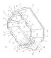
- FIG. 1is a perspective view depicting a line pipe tray
- FIG. 2is a side elevation view depicting the line pipe tray of FIG. 1 ;
- FIG. 3is an end elevation view depicting the line pipe tray of FIG. 1 ;
- FIG. 4is a top plan view depicting the line pipe tray of FIG. 1 ;
- FIG. 5is a bottom plan view depicting the line pipe tray of FIG. 1 ;
- FIG. 6is a cross-section elevation view depicting the line pipe tray of FIG. 4 along section line A-A;
- FIG. 7is a perspective view depicting the line pipe tray of FIG. 1 filled with fluid being poured into a pail.
- line pipe tray 10can comprise substantially parallel opposing outer sidewalls 12 and substantially parallel opposing end walls 14 , and complimentary inner sidewalls 20 and inner end walls 26 that can intersect and adjoin outer sidewalls 12 and outer end walls 14 along top edge 30 .
- line pipe tray 10can comprise traction rib 18 disposed therearound along a lower edge of outer sidewalls 12 and outer end walls 14 to provide stability and structural strength to line pipe tray 10 , and to provide grip or traction in multiple types of ground conditions such as ice, snow, mud, dirt, grass and gravel.
- outer sidewalls 12 and outer end walls 14can taper inwardly towards each other from traction rib 18 to top edge 30 , to provide additional stability and structural strength to line pipe tray 10 .
- line pipe tray 10can further comprise outer corner walls 16 operatively coupling outer sidewalls 12 to outer end walls 14 , and inner corner walls 28 operatively coupling inner sidewalls 24 to inner end walls 26 , wherein outer corner walls 16 and inner corner walls 28 intersect and adjoin along top edge 30 .
- traction rib 18can extend along a lower edge of outer corner walls 16 , and outer walls 16 can taper inwardly from traction rib 18 to top edge 30 .
- outer walls 16provide chamfered corners to line pipe tray 10 , at approximately 135 degrees relative to both of outer sidewalls 12 and outer end walls 14 , to provide additional stability and structural strength to line pipe tray 10 .
- line pipe tray 10can comprise substantially planar bottom surface 22 extending between inner sidewalls 24 , inner end walls 26 and inner corner walls 28 to form basin 20 therebetween.
- line pipe tray 10can further comprise pour channel 42 disposed on one or both of inner end walls 26 tapering outwardly from bottom surface 22 to top edge 30 , thereby forming channel edges 44 disposed between end walls 26 and pour channel 42 .
- pour channel 42can be configured or tapered for pouring fluids of high viscosity.
- pour channel 42can be configured or tapered for pouring fluids of low viscosity.
- line pipe tray 10can comprise pipe saddles 32 disposed on outer and inner end walls 14 and 26 along top edge 30 .
- one or both pipe saddles 32can further comprise pour lip 38 that can intersect with pour channel 42 wherein pour lip 38 can be configured to rest upon, and pour into, a secondary fluid container, such as a pail, when fluids are poured out of basin 20 along pour channel 42 .
- pipe saddles 32can be configured to support the weight of 6.5 inch heavy gauge pipe or lower.
- line pipe tray 10can comprise outer pipe saddles 34 disposed on opposing outer and inner sidewalls 12 and 24 along top edge 30 .
- outer pipe saddles 34can be configured to support the weight of 4 inch heavy gauge pipe or lower.
- line pipe traycan further comprise middle pipe saddles 36 disposed on opposing outer and inner sidewalls 12 and 24 along top edge 30 , and disposed between outer pipe saddles 34 .
- middle pipe saddlescan be configured to support the weight of 5 inch heavy gauge pipe or lower.
- line pipe tray 10can comprise one or more lifting holes or handles 52 disposed through one or both of outer end walls 14 , as shown in FIGS. 1, 3, 4 and 5 that allow personnel to lift and/or move line pipe tray 10 .
- lifting holes 52can be d-shaped in configuration although it is obvious to those skilled in the art that lifting holes 52 can comprise any suitable shape for lifting.
- line pipe tray 10can comprise lifting hole or handle 46 disposed through one or both of outer end walls 14 .
- lifting handle 46can be disposed between lifting handles 52 .
- line pipe tray 10can comprise recess 48 disposed on one or both of outer end walls 14 .
- Recess 48can be a concave depression formed on outer end wall 14 to allow line pipe tray 10 to be placed immediately beside a fluid container or pail prior to pouring fluids from basin 20 .
- lifting handle 46can be arc-shaped, and can further comprise tab 54 disposed therein, wherein tab 54 can be used to hook onto a container or pail to prevent the pail from sliding away from line pipe tray 10 when it is lifted and tilted to pour fluids from basin 20 into the pail. Referring to FIG. 7 , line pipe tray 10 is shown in a lifted and tilted position relative to pail 56 to pour fluids 60 from basin 20 into pail 56 . Lip 58 of pail 56 is inserted into lifting handle 46 , and pail tab 54 is shown hooked onto lip 58 to prevent pail 56 from sliding away from line pipe tray 10 as fluids 60 are being poured over pour lip 38 into pail 56 .
- line pipe tray 10can be comprised of high molecular weight plastic, which can be more resistant to ultra-violet light and can further allow line pipe tray 10 to last longer in outdoor conditions than other types of plastic, and can provide better flexibility.
- line pipe tray 10can be comprised of carbon fibre, fibreglass, composite materials or a combination of any or all of the materials disclosed herein.
- line pipe tray 10can be manufactured using rotational plastic manufacturing techniques, as well known to those skilled in the art. In some embodiments, line pipe tray 10 can be further configured such that multiple line pipe trays 10 can be stacked together when not in use.
Landscapes
- Engineering & Computer Science (AREA)
- General Engineering & Computer Science (AREA)
- Mechanical Engineering (AREA)
- Details Of Rigid Or Semi-Rigid Containers (AREA)
- Sewage (AREA)
Abstract
Description
This application is a continuation of U.S. patent application Ser. No. 13/546,019 filed Jul. 11, 2012, issued as U.S. Pat. No. 8,910,803 B2, which claims the benefit of U.S. Provisional Application No. 61/603,627, entitled “Line Pipe Tray” filed Feb. 27, 2012, and hereby incorporates the same by reference herein in their entirety.
The present disclosure is related to the field of trays used to support pipe, in particular, trays used to support line pipe to or from a producing well, and that further comprise a basin for catching fluids that can spill from a union joint on the pipe.
Line pipe trays are known. They are typically rectangular in structure, when viewed from the top, and can comprise upstanding walls on each side, forming a basin therebetween and therein. They can further comprise saddles disposed on an upper edge on the upstanding walls to cradle line pipe lying thereon. Such line pipe trays are designed to support a singular size of pipe. The line pipe can be used to carry produced substances from a well, or to carry fluids or gases, such as steam, to a well in aid of operations being conducted on the well, as well known to those skilled in the art.
Typically, line pipe trays can be placed on the ground underneath union joints between adjoining pieces of line pipe to support the pipe off of the ground. When a union joint between adjoining pieces of line pipe is uncoupled, any fluids in the pipe can flow out of the ends of the pipe. By having a line pipe tray beneath a union joint, the tray can catch the released fluids. The captured fluids can then be dumped from the tray into another container or storage device for reuse, recycling or disposal, as required.
Current designs of line pipe trays can be flimsy and not structurally sturdy to withstand the weight of the pipe they support or the fluids captured and/or may be physically difficult to handle or move so as to pour the fluids in the basin of the tray to another container.
It is, therefore, desirable to provide a line pipe tray that overcomes the shortcomings of prior art designs of line pipe trays.
Broadly stated, in some embodiments, a line pipe tray for supporting a line pipe is provided, the line pipe tray comprising a pair of outer sidewalls each having bottom edges and top edges, the outer sidewalls being tilted towards each other wherein the distance between the bottom edges thereof is larger than the distance between the top edges thereof; a pair of outer end walls each having bottom edges and top edges, the outer end walls being tilted towards each other wherein the distance between the bottom edges thereof is larger than the distance between the top edges thereof, the outer end walls being operatively coupled to the outer sidewalls; a pair of inner sidewalls each having bottom edges and top edges, said top edges intersecting with, and operatively coupled to, the top edges of the outer sidewalls thereby forming a pair of sidewall top edges; a pair of inner end walls each having bottom edges and top edges, said top edges intersecting with, and operatively coupled to, the top edges of the outer end walls thereby forming a pair of end wall top edges, the inner end walls being operatively coupled to the inner sidewalls; and a bottom surface disposed between and operatively coupled to the bottom edges of the inner sidewalls and the inner end walls, wherein a basin is formed therebetween. A pipe saddle may be disposed on each of the end wall top edges.
Broadly stated, in some embodiments, the line pipe tray can further comprise a plurality of outer corner walls each having bottom edges and top edges, the outer corner walls operatively coupling the outer sidewalls to the outer end walls; and a plurality of inner corner walls each having bottom edges and top edges, said top edges intersecting with, and operatively coupled to, the top edges of the outer corner walls thereby forming corner wall top edges, the inner corner walls operatively coupling the inner sidewalls to the inner end walls.
Broadly stated, in some embodiments, the line pipe tray can further comprise a pair of end wall pipe saddles, each end wall pipe saddle disposed on the end wall top edges.
Broadly stated, in some embodiments, at least one of the end pipe saddles can further comprise a pour lip, the pour lip extending outwardly from the outer end wall.
Broadly stated, in some embodiments, the line pipe tray can further comprise a plurality of outer pipe saddles, each outer pipe saddle disposed on the sidewall top edges nearer the outer end walls.
Broadly stated, in some embodiments, the line pipe tray can further comprise a pair of middle pipe saddles, each middle pipe saddle disposed on the sidewall top edges between the outer pipe saddles.
Broadly stated, in some embodiments, at least one of the inner end walls can further comprise a pour channel disposed thereon.
Broadly stated, in some embodiments, the line pipe tray can further comprise a recess disposed on one or both of the outer end walls for a pail or fluid container.
Broadly stated, in some embodiments, the line pipe tray can further comprise a first lifting handle disposed through one or both of the outer end walls.
Broadly stated, in some embodiments, the line pipe tray can further comprise a tab disposed on the outer end wall extending into the first lifting handle for hooking onto a pail or fluid container.
Broadly stated, in some embodiments, the line pipe tray can further comprise one or more second lifting handles disposed through one or both of the outer end walls.
Broadly stated, in some embodiments, the line pipe tray can further comprise a traction rib disposed along the bottom edges of the outer sidewalls and the outer end walls.
The foregoing aspects and many of the attendant advantages of this invention will become more readily appreciated as the same become better understood by reference to the following detailed description, when taken in conjunction with the accompanying drawings, wherein:
An improved line pipe tray is provided. Referring toFIGS. 1 to 6 , an embodiment ofline pipe tray 10 is shown. In some embodiments,line pipe tray 10 can comprise substantially parallel opposingouter sidewalls 12 and substantially parallelopposing end walls 14, and complimentaryinner sidewalls 20 andinner end walls 26 that can intersect and adjoinouter sidewalls 12 andouter end walls 14 alongtop edge 30. In some embodiments,line pipe tray 10 can comprisetraction rib 18 disposed therearound along a lower edge ofouter sidewalls 12 andouter end walls 14 to provide stability and structural strength toline pipe tray 10, and to provide grip or traction in multiple types of ground conditions such as ice, snow, mud, dirt, grass and gravel. In some embodiments,outer sidewalls 12 andouter end walls 14 can taper inwardly towards each other fromtraction rib 18 totop edge 30, to provide additional stability and structural strength toline pipe tray 10.
In some embodiments,line pipe tray 10 can further compriseouter corner walls 16 operatively couplingouter sidewalls 12 toouter end walls 14, andinner corner walls 28 operatively couplinginner sidewalls 24 toinner end walls 26, whereinouter corner walls 16 andinner corner walls 28 intersect and adjoin alongtop edge 30. In further embodiments,traction rib 18 can extend along a lower edge ofouter corner walls 16, andouter walls 16 can taper inwardly fromtraction rib 18 totop edge 30. In some embodiments,outer walls 16 provide chamfered corners toline pipe tray 10, at approximately 135 degrees relative to both ofouter sidewalls 12 andouter end walls 14, to provide additional stability and structural strength toline pipe tray 10.
In some embodiments,line pipe tray 10 can comprise substantiallyplanar bottom surface 22 extending betweeninner sidewalls 24,inner end walls 26 andinner corner walls 28 to formbasin 20 therebetween. In some embodiments,line pipe tray 10 can further comprise pourchannel 42 disposed on one or both ofinner end walls 26 tapering outwardly frombottom surface 22 totop edge 30, thereby formingchannel edges 44 disposed betweenend walls 26 and pourchannel 42. In some embodiments, pourchannel 42 can be configured or tapered for pouring fluids of high viscosity. In some embodiments, pourchannel 42 can be configured or tapered for pouring fluids of low viscosity.
In some embodiments,line pipe tray 10 can comprisepipe saddles 32 disposed on outer andinner end walls top edge 30. In some embodiments, one or bothpipe saddles 32 can further comprise pourlip 38 that can intersect withpour channel 42 wherein pourlip 38 can be configured to rest upon, and pour into, a secondary fluid container, such as a pail, when fluids are poured out ofbasin 20 along pourchannel 42. In some embodiments,pipe saddles 32 can be configured to support the weight of 6.5 inch heavy gauge pipe or lower.
In some embodiments,line pipe tray 10 can compriseouter pipe saddles 34 disposed on opposing outer andinner sidewalls top edge 30. In some embodiments,outer pipe saddles 34 can be configured to support the weight of 4 inch heavy gauge pipe or lower. In some embodiments, line pipe tray can further comprisemiddle pipe saddles 36 disposed on opposing outer andinner sidewalls top edge 30, and disposed betweenouter pipe saddles 34. In some embodiments, middle pipe saddles can be configured to support the weight of 5 inch heavy gauge pipe or lower.
In some embodiments,line pipe tray 10 can comprise one or more lifting holes orhandles 52 disposed through one or both ofouter end walls 14, as shown inFIGS. 1, 3, 4 and 5 that allow personnel to lift and/or moveline pipe tray 10. In some embodiments,lifting holes 52 can be d-shaped in configuration although it is obvious to those skilled in the art that liftingholes 52 can comprise any suitable shape for lifting. In some embodiments,line pipe tray 10 can comprise lifting hole orhandle 46 disposed through one or both ofouter end walls 14. In some embodiments, liftinghandle 46 can be disposed between lifting handles52.
In some embodiments,line pipe tray 10 can compriserecess 48 disposed on one or both ofouter end walls 14.Recess 48 can be a concave depression formed onouter end wall 14 to allowline pipe tray 10 to be placed immediately beside a fluid container or pail prior to pouring fluids frombasin 20. In some embodiments, liftinghandle 46 can be arc-shaped, and can further comprisetab 54 disposed therein, whereintab 54 can be used to hook onto a container or pail to prevent the pail from sliding away fromline pipe tray 10 when it is lifted and tilted to pour fluids frombasin 20 into the pail. Referring toFIG. 7 ,line pipe tray 10 is shown in a lifted and tilted position relative topail 56 to pourfluids 60 frombasin 20 intopail 56.Lip 58 ofpail 56 is inserted into liftinghandle 46, andpail tab 54 is shown hooked ontolip 58 to preventpail 56 from sliding away fromline pipe tray 10 asfluids 60 are being poured over pourlip 38 intopail 56.
In some embodiments,line pipe tray 10 can be comprised of high molecular weight plastic, which can be more resistant to ultra-violet light and can further allowline pipe tray 10 to last longer in outdoor conditions than other types of plastic, and can provide better flexibility. In some embodiments,line pipe tray 10 can be comprised of carbon fibre, fibreglass, composite materials or a combination of any or all of the materials disclosed herein.
In some embodiments,line pipe tray 10 can be manufactured using rotational plastic manufacturing techniques, as well known to those skilled in the art. In some embodiments,line pipe tray 10 can be further configured such that multipleline pipe trays 10 can be stacked together when not in use.
Although a few embodiments have been shown and described, it will be appreciated by those skilled in the art that various changes and modifications might be made without departing from the scope of the invention. The terms and expressions used in the preceding specification have been used herein as terms of description and not of limitation, and there is no intention in the use of such terms and expressions of excluding equivalents of the features shown and described or portions thereof, it being recognized that the invention is defined and limited only by the claims that follow.
Claims (3)
1. A line pipe tray for supporting a line pipe, the line pipe tray comprising:
a basin formed from a bottom surface disposed between and operatively coupled to a plurality of walls that include a first pair of walls and a second pair of walls;
a first pair of pipe saddles with each saddle disposed on respective walls of the first pair of walls; and
a first pour channel disposed on a wall of the plurality of walls with a tab that forms a hook extending outwardly on the wall below the first pour channel for hooking onto a container or pail to prevent the container or pail from sliding away when the line pipe tray is lifted and tilted to pour fluids from the line pipe tray into the container or pail, wherein the plurality of walls comprise outer walls having bottom edges and top edges, the outer walls tilted towards each other, wherein the distance between the bottom edges thereof is larger than the distance between the top edges thereof, and inner walls having bottom edges and top edges, said top edges intersecting with and operatively coupled to the top edges of the outer walls, thereby forming wall top edges, wherein the bottom surface is disposed between and operatively coupled to the bottom edges of the inner walls; and
further comprising at least a first lifting handle disposed through any one of the outer walls, wherein the tab extends into the first lifting handle.
2. A line pipe tray for supporting a line pipe, the line pipe tray comprising:
a basin formed from a bottom surface disposed between and operatively coupled to a plurality of walls that include a first pair of walls and a second pair of walls;
a first pair of pipe saddles with each saddle disposed on respective walls of the first pair of walls; and
a first pour channel disposed on a wall of the plurality of walls with a tab that forms a hook extending outwardly on the wall below the first pour channel for hooking onto a container or pail to prevent the container or pail from sliding away when the line pipe tray is lifted and tilted to pour fluids from the line pipe tray into the container or pail, wherein the tab extends from an arc-shaped opening disposed in the corresponding wall.
3. The line pipe tray ofclaim 2 , in which the arc-shaped opening has a concave lower edge shaped to fit a curved wall of the container or pail.
Priority Applications (1)
| Application Number | Priority Date | Filing Date | Title |
|---|---|---|---|
| US14/556,857US9488295B2 (en) | 2012-02-27 | 2014-12-01 | Line pipe tray |
Applications Claiming Priority (3)
| Application Number | Priority Date | Filing Date | Title |
|---|---|---|---|
| US201261603627P | 2012-02-27 | 2012-02-27 | |
| US13/546,019US8910803B2 (en) | 2012-02-27 | 2012-07-11 | Line pipe tray |
| US14/556,857US9488295B2 (en) | 2012-02-27 | 2014-12-01 | Line pipe tray |
Related Parent Applications (1)
| Application Number | Title | Priority Date | Filing Date |
|---|---|---|---|
| US13/546,019ContinuationUS8910803B2 (en) | 2012-02-27 | 2012-07-11 | Line pipe tray |
Publications (2)
| Publication Number | Publication Date |
|---|---|
| US20150144744A1 US20150144744A1 (en) | 2015-05-28 |
| US9488295B2true US9488295B2 (en) | 2016-11-08 |
Family
ID=49001704
Family Applications (2)
| Application Number | Title | Priority Date | Filing Date |
|---|---|---|---|
| US13/546,019ActiveUS8910803B2 (en) | 2012-02-27 | 2012-07-11 | Line pipe tray |
| US14/556,857ActiveUS9488295B2 (en) | 2012-02-27 | 2014-12-01 | Line pipe tray |
Family Applications Before (1)
| Application Number | Title | Priority Date | Filing Date |
|---|---|---|---|
| US13/546,019ActiveUS8910803B2 (en) | 2012-02-27 | 2012-07-11 | Line pipe tray |
Country Status (9)
| Country | Link |
|---|---|
| US (2) | US8910803B2 (en) |
| EP (1) | EP2820339B1 (en) |
| AR (1) | AR088080A1 (en) |
| BR (1) | BR112014021253B8 (en) |
| CA (1) | CA2778076C (en) |
| CO (1) | CO7141450A2 (en) |
| MX (1) | MX361319B (en) |
| TR (1) | TR201907968T4 (en) |
| WO (1) | WO2013126983A1 (en) |
Cited By (5)
| Publication number | Priority date | Publication date | Assignee | Title |
|---|---|---|---|---|
| USD889943S1 (en)* | 2019-01-10 | 2020-07-14 | Southwest Agri-Plastics, Inc. | Pipe support |
| USD941122S1 (en) | 2019-07-11 | 2022-01-18 | Southwest Agri-Plastics, Inc. | Pipe support |
| US11280430B2 (en)* | 2018-07-12 | 2022-03-22 | DuraPlas, LP | Pipe support |
| USD1002339S1 (en)* | 2020-05-11 | 2023-10-24 | DuraPlas, LP | Pipe stand |
| USD1002340S1 (en)* | 2020-06-26 | 2023-10-24 | DC Invents, LLC | Bracket insert |
Families Citing this family (32)
| Publication number | Priority date | Publication date | Assignee | Title |
|---|---|---|---|---|
| USD336891S (en)* | 1990-09-14 | 1993-06-29 | Hirose Electric Co., Ltd. | Terminal for an electrical connector |
| CA2778076C (en) | 2012-02-27 | 2017-10-31 | Katch Kan Holdings Ltd. | Line pipe tray |
| US9453392B1 (en) | 2012-05-04 | 2016-09-27 | D Ring Solutions, LLC | Rapid install environmental tray |
| US20140076910A1 (en)* | 2012-09-20 | 2014-03-20 | David McConnell | Carrier Devices And Carrier Systems For Carrying And Transporting Containers |
| US20150028177A1 (en)* | 2013-07-24 | 2015-01-29 | Michael Vargas | Trailer jack stand support |
| USD738711S1 (en) | 2013-08-30 | 2015-09-15 | Cooper Technologies Company | Rooftop support |
| US20150237839A1 (en)* | 2014-02-27 | 2015-08-27 | Alan A. Hermanson | Ice fishing tip-up holder |
| US20170020341A1 (en)* | 2015-07-20 | 2017-01-26 | Duane Farmer | Multi-function kitchen utensil |
| US10273694B2 (en) | 2017-03-03 | 2019-04-30 | Zsi-Foster, Inc. | Rooftop support system |
| FR3070990B1 (en)* | 2017-09-13 | 2019-08-30 | Yannick Joubeaux | POSITIONING AND SPLITTING DEVICE FOR PIPES INTENDED TO BE POSITIONED IN A TRENCH |
| USD839628S1 (en)* | 2018-02-28 | 2019-02-05 | Avraham Gilor | Razor stand |
| US11486516B2 (en)* | 2018-02-28 | 2022-11-01 | Earth Tek Construction Inc. | Concrete pump hose support |
| USD866302S1 (en)* | 2018-08-31 | 2019-11-12 | Ykk Corporation | Retaining box for slide fastener |
| USD873117S1 (en)* | 2018-09-06 | 2020-01-21 | MJR 2000 Holdings Ltd. | Electrical cord mount |
| USD926022S1 (en)* | 2018-09-12 | 2021-07-27 | Craig J. Luhrmann | Weight for submerged tubing |
| CA184239S (en)* | 2018-10-22 | 2019-10-18 | Cascades Canada Ulc | Bushing for a paper roll |
| USD879592S1 (en)* | 2018-10-30 | 2020-03-31 | MarketMakers (Aust.) Pty Ltd | Curtain cord guide |
| USD878906S1 (en)* | 2018-12-13 | 2020-03-24 | Marine Town Inc. | Swing locker |
| USD893285S1 (en)* | 2019-01-25 | 2020-08-18 | Bup Labs, LLC | Mount apparatus |
| US11083297B1 (en)* | 2019-02-11 | 2021-08-10 | Ricardo Alonzo | Portable easel |
| USD878907S1 (en)* | 2019-03-08 | 2020-03-24 | Prism Fitness, Inc. | Rope saddle and anchor for a rope caddy |
| USD880282S1 (en)* | 2019-03-29 | 2020-04-07 | Jarred Lee Wheeler | Hose guide for tires |
| US11560775B2 (en)* | 2019-10-01 | 2023-01-24 | Brandon Bullock | Catwalk fluid and ground protection recovery system |
| US11391395B2 (en) | 2020-03-11 | 2022-07-19 | Branson Sherman | Pipe-support device |
| US11840859B2 (en) | 2020-09-11 | 2023-12-12 | Illinois Tool Works Inc. | Wire strand attachment clip |
| USD979378S1 (en)* | 2020-09-11 | 2023-02-28 | Illinois Tool Works Inc. | Wire strand attachment clip |
| USD966081S1 (en)* | 2021-05-26 | 2022-10-11 | Hua Li | Cord management device |
| USD976690S1 (en)* | 2022-06-21 | 2023-01-31 | Jie Peng | Double hook |
| US20250060050A1 (en)* | 2023-08-17 | 2025-02-20 | Channel Master, Llc | Cable/tubular clamp and system using the same |
| US12275128B2 (en)* | 2023-08-29 | 2025-04-15 | Jun-Fan Chen | Tool holder |
| USD1085851S1 (en)* | 2023-10-09 | 2025-07-29 | Kevin Andrew Holder | Tubing holder |
| USD1067026S1 (en)* | 2023-12-18 | 2025-03-18 | Linpeng Jia | Cable clamp |
Citations (90)
| Publication number | Priority date | Publication date | Assignee | Title |
|---|---|---|---|---|
| CA86793A (en) | 1903-12-30 | 1904-04-26 | Seymour S. Cook | Evaporator |
| CA144032A (en) | 1912-09-13 | 1912-11-12 | William Leclair Jr. | Mail bag mechanism |
| US1298258A (en)* | 1915-08-19 | 1919-03-25 | Ric Wil Underground Pipe Covering Company | Drainage system. |
| US1531569A (en) | 1923-09-27 | 1925-03-31 | William C Rade | Combination cake pan |
| US1858101A (en)* | 1928-08-27 | 1932-05-10 | Robert W Mcafee | Sealing box, brace, and liner for underground pipes |
| US2314835A (en)* | 1940-12-19 | 1943-03-23 | Thomas H Johns | Bucket |
| US2849027A (en)* | 1953-12-23 | 1958-08-26 | John J Tetyak | Pipe shoe |
| US3026076A (en)* | 1960-10-07 | 1962-03-20 | Tejas Plastics Materials Suppl | Support for pipeline |
| US3292815A (en) | 1965-08-05 | 1966-12-20 | Wooster Brush Co | Pail |
| US3333727A (en)* | 1965-03-18 | 1967-08-01 | Owens Illinois Inc | Beverage bottle case |
| US3782582A (en)* | 1971-04-26 | 1974-01-01 | D Atwood | Core tray |
| US3829926A (en) | 1972-10-05 | 1974-08-20 | Action Inc | Paint bucket |
| US3993192A (en)* | 1975-11-10 | 1976-11-23 | Christopher Brian Bunn | Pipeline weight container and method |
| USD249233S (en) | 1976-11-15 | 1978-09-05 | Mobil Oil Corporation | Packaging tray or the like |
| US4475604A (en) | 1982-08-09 | 1984-10-09 | The Charles Machine Works, Inc. | Mobile machine for subterranean installation of piping and the like |
| US4484661A (en) | 1983-04-07 | 1984-11-27 | Evenson John L | Drip pan for vehicles |
| US4502653A (en)* | 1982-12-22 | 1985-03-05 | Miro Industries, Inc. | Pipe supporting device |
| US4513934A (en)* | 1982-11-03 | 1985-04-30 | Miro Industries, Inc. | Pipe-supporting device |
| US4651887A (en) | 1986-01-08 | 1987-03-24 | Ashland Oil, Inc. | Spill catch pan |
| US4687185A (en)* | 1985-06-14 | 1987-08-18 | Nippon Piston Ring Co., Ltd. | Tool for supporting a composite camshaft during sintering |
| US4899963A (en)* | 1989-02-06 | 1990-02-13 | Murphy Patrick J | Support saddle for elongate articles and interpositioning device for dissimilar surfaces |
| US4901870A (en)* | 1988-11-14 | 1990-02-20 | Wright Tim E | Spacer for support of cylindrical rolls |
| USD315668S (en)* | 1989-07-25 | 1991-03-26 | K&P Products, Inc. | Securing and support device for conduits, pipes, or the like |
| US5072901A (en)* | 1990-06-20 | 1991-12-17 | Lyle Scott | Pipe support stand |
| US5107654A (en)* | 1988-10-07 | 1992-04-28 | Nicola Leonardis | Foundation reinforcement chairs |
| US5207325A (en)* | 1991-07-11 | 1993-05-04 | Kennedy Patricia B | Instrument storage tray |
| USD363662S (en) | 1994-02-08 | 1995-10-31 | Good Humor Corporation | Container |
| CA2166265A1 (en) | 1995-12-28 | 1997-06-29 | Quinn Holtby | Method and Apparatus for Preventing Environmental Contamination Due to Fluid Leakage from a Wellhead |
| USD384778S (en) | 1996-04-29 | 1997-10-07 | Kennel-Aire, Inc. | Tray for a pet cage |
| USD389307S (en) | 1996-04-04 | 1998-01-20 | Wade Zimmerman | Stackable two-piece container for a cylinder head |
| US5729949A (en)* | 1996-09-09 | 1998-03-24 | Hartzheim; G. Douglas | Slab on grade chair |
| US5775869A (en) | 1996-10-15 | 1998-07-07 | Trans Environmental Systems, Inc. | Transportable spill containment pan |
| USD399727S (en)* | 1997-03-17 | 1998-10-20 | Herbert Richter | Holder for supporting rod-like objects |
| US5823382A (en) | 1994-12-19 | 1998-10-20 | Koninklijke Emballage Industrie Van Leer B.V. | Baseplate for a pallet container |
| USD408726S (en)* | 1996-05-31 | 1999-04-27 | Vallee Pipe Supports Ltd. | Pipe support |
| USD411674S (en)* | 1998-05-22 | 1999-06-29 | Rubbermaid Incorporated | Dual bucket |
| US5918751A (en)* | 1994-09-22 | 1999-07-06 | Tulip Corporation | Display tray |
| US5941410A (en)* | 1996-11-12 | 1999-08-24 | Mangano; Joy | Mop bucket having a mop stabilizing structure |
| US5975342A (en)* | 1997-03-28 | 1999-11-02 | Stephen E. Bradeen | Large mug and beverage container holder |
| USD420277S (en)* | 1999-03-03 | 2000-02-08 | First Services, L.L.C. | Stabilizer for elongated objects |
| US6065633A (en)* | 1997-06-25 | 2000-05-23 | Roller Coater, Inc. | Multi-purpose receptacle |
| US6102086A (en) | 1998-04-07 | 2000-08-15 | Holtby; Quinn | Drip tray |
| US6105813A (en)* | 1997-06-25 | 2000-08-22 | Roller Coater, Inc. | Multi purpose paint bucket |
| US6116266A (en) | 1997-11-17 | 2000-09-12 | Retriever Products Pty. Ltd. | Liquid collection tray |
| USD432361S (en) | 1998-02-13 | 2000-10-24 | Linpac Plastics Limited | Tray |
| USD436522S1 (en)* | 2000-02-02 | 2001-01-23 | Miro Industries, Inc. | Pipe supporting device |
| US6250591B1 (en)* | 1999-04-27 | 2001-06-26 | Michael E. Cunningham | Conduit support assembly |
| US6401960B1 (en)* | 2001-06-29 | 2002-06-11 | Norseman Plastics Limited | Two liter bottle crate |
| US6446827B1 (en) | 2001-10-03 | 2002-09-10 | R. W. Akins | Paint container and dispenser apparatus for use with a paint brush |
| US6520456B1 (en)* | 2000-03-31 | 2003-02-18 | Miro Industries, Inc. | Pipe supporting devices |
| US20030089829A1 (en)* | 2001-11-15 | 2003-05-15 | Michael Brandzel | Cable to frame fastener system |
| US6648281B1 (en)* | 2002-02-22 | 2003-11-18 | Western Oilfields Supply Co. | Portable spill containment bridge and hose and cable support system |
| CA102346S (en) | 2003-03-07 | 2004-02-20 | Heide William | Connector tray |
| USD493670S1 (en) | 2001-02-20 | 2004-08-03 | Dester .Acs Holding B.V. | Elongated tray |
| US6824115B1 (en)* | 2003-03-28 | 2004-11-30 | Richard Batson | Paint tray holder |
| USD500243S1 (en)* | 2004-01-15 | 2004-12-28 | James N. Turek, Sr. | Rebar, beam and mesh highchair |
| US6932449B2 (en)* | 2003-02-13 | 2005-08-23 | Maytag Corporation | Multi-functional beverage storage rack for a refrigerator |
| US7007978B1 (en)* | 2004-05-27 | 2006-03-07 | Erik Purdom | Skate activities rail support |
| US20060064843A1 (en)* | 2003-05-14 | 2006-03-30 | Maria Cornelissen Rudolphus Jo | Paint roller tray for placing on a paint container |
| US20060091265A1 (en)* | 2004-10-28 | 2006-05-04 | Freedom, Inc. | Support block system |
| USD521851S1 (en)* | 2004-03-09 | 2006-05-30 | Kenneth Smart | Gas tube block support |
| US20060131469A1 (en)* | 2004-12-20 | 2006-06-22 | Roy David E | Pipeline skid and a skid system for use in pipeline construction |
| USD525820S1 (en) | 2004-04-19 | 2006-08-01 | Oztiryakiler Madeni Esya Sanayi ve Ticaret Anonim Sirketi | Gastronorm basin |
| USD527506S1 (en)* | 2005-05-10 | 2006-08-29 | Harper Bursh Works, Inc, | Mop bucket |
| USD537996S1 (en)* | 2004-10-14 | 2007-03-06 | Lundy Michael J | Painter's bucket |
| USD543134S1 (en) | 2005-10-26 | 2007-05-22 | Cox L Courtney | Potting tray |
| USD573411S1 (en) | 2006-07-31 | 2008-07-22 | Innoware Plastic, Inc. | Food tray |
| US20080308556A1 (en)* | 2005-10-24 | 2008-12-18 | Akzo Nobel Coating International B.V. | Lidded Container |
| US7497405B2 (en)* | 2006-11-06 | 2009-03-03 | Weixiong Huo | ESL and P.V.C. pipe support |
| USD600113S1 (en) | 2006-12-20 | 2009-09-15 | Kraft Foods Global Brands Llc | Reclosable package |
| CA128113S (en) | 2008-10-16 | 2009-09-23 | Safety Spill Systems Inc | Line pipe tray |
| US7607619B2 (en)* | 2005-08-31 | 2009-10-27 | Freedom, Inc. | Slotted conduit support block system |
| US20090277913A1 (en)* | 2008-05-12 | 2009-11-12 | Bercom International, Llc | Ergonomic Paint Roller Tray With End Handles |
| USD604920S1 (en)* | 2009-02-10 | 2009-11-24 | Bercom International, Llc | Paint tray |
| US20090302563A1 (en)* | 2008-06-09 | 2009-12-10 | Thibault Richard R | Painters wheeled caddy |
| US7637387B1 (en) | 2007-09-21 | 2009-12-29 | Christopher Ralph Cantolino | Fluid collection and drain pan with integrated strength-enhancing structure |
| US7644819B2 (en)* | 2007-05-10 | 2010-01-12 | Genie Carriers Ltd. | Apparatus for secure transport of containers |
| US7731131B2 (en) | 2008-08-15 | 2010-06-08 | Dymotek, Inc. | Roof block |
| US7798920B1 (en)* | 2004-10-18 | 2010-09-21 | Cortes Dagoberto S | Sporting activity system |
| US20110101000A1 (en)* | 2009-11-03 | 2011-05-05 | Cutler Sr Willard G | Tray or pan |
| US20120152961A1 (en)* | 2010-12-16 | 2012-06-21 | Diblasi Mike | Paint pan and integrated utensil cleaner |
| US8281952B2 (en) | 2003-01-16 | 2012-10-09 | Valspar Sourcing, Inc. | Resealable containers having internal roller surface |
| US8292238B2 (en)* | 2004-12-08 | 2012-10-23 | General Electric Company | Thrust bearing support assembly for a gas turbine engine |
| US8479945B1 (en) | 2012-02-02 | 2013-07-09 | Simmons Inventions Llc | Universal drain pan |
| WO2013126983A1 (en) | 2012-02-27 | 2013-09-06 | Katch Kan Holdings Ltd. | Line pipe tray |
| US8613373B2 (en) | 2012-05-18 | 2013-12-24 | Quinn A. J. Holtby | Tubing tray and method for using same for collecting fluids draining from drill pipe |
| US8701923B2 (en) | 2010-06-30 | 2014-04-22 | S.C. Johnson & Son, Inc. | Containers with anti-buckling structural features |
| CA2777704C (en) | 2012-05-18 | 2014-08-26 | Katch Kan Holdings Ltd. | Tubing tray and method for using same for collecting fluids draining from drill pipe |
| USD715623S1 (en) | 2012-01-19 | 2014-10-21 | Katch Kan Holdings Ltd. | Heavy duty line pipe tray |
| USD718610S1 (en) | 2012-05-08 | 2014-12-02 | Katch Kan Holdings Ltd. | Tubing tray |
Family Cites Families (2)
| Publication number | Priority date | Publication date | Assignee | Title |
|---|---|---|---|---|
| CA102346A (en) | 1906-10-25 | 1906-12-04 | Edward J. Fuller | Metallic packing |
| CA128113A (en) | 1907-08-19 | 1910-09-13 | John E. Greenawalt | Process of subjecting materials to the action of air, etc. |
- 2012
- 2012-05-24CACA2778076Apatent/CA2778076C/enactiveActive
- 2012-05-25WOPCT/CA2012/000501patent/WO2013126983A1/enactiveApplication Filing
- 2012-05-25MXMX2014010313Apatent/MX361319B/enactiveIP Right Grant
- 2012-05-25TRTR2019/07968Tpatent/TR201907968T4/enunknown
- 2012-05-25EPEP12869820.6Apatent/EP2820339B1/enactiveActive
- 2012-05-25BRBR112014021253Apatent/BR112014021253B8/enactiveIP Right Grant
- 2012-07-11USUS13/546,019patent/US8910803B2/enactiveActive
- 2012-09-27ARARP120103595Apatent/AR088080A1/enactiveIP Right Grant
- 2014
- 2014-08-27COCO14188336Apatent/CO7141450A2/enunknown
- 2014-12-01USUS14/556,857patent/US9488295B2/enactiveActive
Patent Citations (94)
| Publication number | Priority date | Publication date | Assignee | Title |
|---|---|---|---|---|
| CA86793A (en) | 1903-12-30 | 1904-04-26 | Seymour S. Cook | Evaporator |
| CA144032A (en) | 1912-09-13 | 1912-11-12 | William Leclair Jr. | Mail bag mechanism |
| US1298258A (en)* | 1915-08-19 | 1919-03-25 | Ric Wil Underground Pipe Covering Company | Drainage system. |
| US1531569A (en) | 1923-09-27 | 1925-03-31 | William C Rade | Combination cake pan |
| US1858101A (en)* | 1928-08-27 | 1932-05-10 | Robert W Mcafee | Sealing box, brace, and liner for underground pipes |
| US2314835A (en)* | 1940-12-19 | 1943-03-23 | Thomas H Johns | Bucket |
| US2849027A (en)* | 1953-12-23 | 1958-08-26 | John J Tetyak | Pipe shoe |
| US3026076A (en)* | 1960-10-07 | 1962-03-20 | Tejas Plastics Materials Suppl | Support for pipeline |
| US3333727A (en)* | 1965-03-18 | 1967-08-01 | Owens Illinois Inc | Beverage bottle case |
| US3292815A (en) | 1965-08-05 | 1966-12-20 | Wooster Brush Co | Pail |
| US3782582A (en)* | 1971-04-26 | 1974-01-01 | D Atwood | Core tray |
| US3829926A (en) | 1972-10-05 | 1974-08-20 | Action Inc | Paint bucket |
| US3993192A (en)* | 1975-11-10 | 1976-11-23 | Christopher Brian Bunn | Pipeline weight container and method |
| USD249233S (en) | 1976-11-15 | 1978-09-05 | Mobil Oil Corporation | Packaging tray or the like |
| US4475604A (en) | 1982-08-09 | 1984-10-09 | The Charles Machine Works, Inc. | Mobile machine for subterranean installation of piping and the like |
| US4513934A (en)* | 1982-11-03 | 1985-04-30 | Miro Industries, Inc. | Pipe-supporting device |
| US4502653A (en)* | 1982-12-22 | 1985-03-05 | Miro Industries, Inc. | Pipe supporting device |
| US4484661A (en) | 1983-04-07 | 1984-11-27 | Evenson John L | Drip pan for vehicles |
| US4687185A (en)* | 1985-06-14 | 1987-08-18 | Nippon Piston Ring Co., Ltd. | Tool for supporting a composite camshaft during sintering |
| US4651887A (en) | 1986-01-08 | 1987-03-24 | Ashland Oil, Inc. | Spill catch pan |
| US5107654A (en)* | 1988-10-07 | 1992-04-28 | Nicola Leonardis | Foundation reinforcement chairs |
| US4901870A (en)* | 1988-11-14 | 1990-02-20 | Wright Tim E | Spacer for support of cylindrical rolls |
| US4899963A (en)* | 1989-02-06 | 1990-02-13 | Murphy Patrick J | Support saddle for elongate articles and interpositioning device for dissimilar surfaces |
| USD315668S (en)* | 1989-07-25 | 1991-03-26 | K&P Products, Inc. | Securing and support device for conduits, pipes, or the like |
| US5072901A (en)* | 1990-06-20 | 1991-12-17 | Lyle Scott | Pipe support stand |
| US5207325A (en)* | 1991-07-11 | 1993-05-04 | Kennedy Patricia B | Instrument storage tray |
| USD363662S (en) | 1994-02-08 | 1995-10-31 | Good Humor Corporation | Container |
| US5918751A (en)* | 1994-09-22 | 1999-07-06 | Tulip Corporation | Display tray |
| US5823382A (en) | 1994-12-19 | 1998-10-20 | Koninklijke Emballage Industrie Van Leer B.V. | Baseplate for a pallet container |
| CA2166265A1 (en) | 1995-12-28 | 1997-06-29 | Quinn Holtby | Method and Apparatus for Preventing Environmental Contamination Due to Fluid Leakage from a Wellhead |
| USD389307S (en) | 1996-04-04 | 1998-01-20 | Wade Zimmerman | Stackable two-piece container for a cylinder head |
| USD384778S (en) | 1996-04-29 | 1997-10-07 | Kennel-Aire, Inc. | Tray for a pet cage |
| USD408726S (en)* | 1996-05-31 | 1999-04-27 | Vallee Pipe Supports Ltd. | Pipe support |
| US5729949A (en)* | 1996-09-09 | 1998-03-24 | Hartzheim; G. Douglas | Slab on grade chair |
| US5775869A (en) | 1996-10-15 | 1998-07-07 | Trans Environmental Systems, Inc. | Transportable spill containment pan |
| US5941410A (en)* | 1996-11-12 | 1999-08-24 | Mangano; Joy | Mop bucket having a mop stabilizing structure |
| USD399727S (en)* | 1997-03-17 | 1998-10-20 | Herbert Richter | Holder for supporting rod-like objects |
| US5975342A (en)* | 1997-03-28 | 1999-11-02 | Stephen E. Bradeen | Large mug and beverage container holder |
| US6105813A (en)* | 1997-06-25 | 2000-08-22 | Roller Coater, Inc. | Multi purpose paint bucket |
| US6065633A (en)* | 1997-06-25 | 2000-05-23 | Roller Coater, Inc. | Multi-purpose receptacle |
| US6116266A (en) | 1997-11-17 | 2000-09-12 | Retriever Products Pty. Ltd. | Liquid collection tray |
| USD432361S (en) | 1998-02-13 | 2000-10-24 | Linpac Plastics Limited | Tray |
| US6102086A (en) | 1998-04-07 | 2000-08-15 | Holtby; Quinn | Drip tray |
| USD411674S (en)* | 1998-05-22 | 1999-06-29 | Rubbermaid Incorporated | Dual bucket |
| USD420277S (en)* | 1999-03-03 | 2000-02-08 | First Services, L.L.C. | Stabilizer for elongated objects |
| US6250591B1 (en)* | 1999-04-27 | 2001-06-26 | Michael E. Cunningham | Conduit support assembly |
| USD436522S1 (en)* | 2000-02-02 | 2001-01-23 | Miro Industries, Inc. | Pipe supporting device |
| US6520456B1 (en)* | 2000-03-31 | 2003-02-18 | Miro Industries, Inc. | Pipe supporting devices |
| USD493670S1 (en) | 2001-02-20 | 2004-08-03 | Dester .Acs Holding B.V. | Elongated tray |
| US6401960B1 (en)* | 2001-06-29 | 2002-06-11 | Norseman Plastics Limited | Two liter bottle crate |
| US6446827B1 (en) | 2001-10-03 | 2002-09-10 | R. W. Akins | Paint container and dispenser apparatus for use with a paint brush |
| US20030089829A1 (en)* | 2001-11-15 | 2003-05-15 | Michael Brandzel | Cable to frame fastener system |
| US6889944B2 (en)* | 2001-11-15 | 2005-05-10 | Michael Brandzel | Cable to frame fastener system |
| US6648281B1 (en)* | 2002-02-22 | 2003-11-18 | Western Oilfields Supply Co. | Portable spill containment bridge and hose and cable support system |
| US8281952B2 (en) | 2003-01-16 | 2012-10-09 | Valspar Sourcing, Inc. | Resealable containers having internal roller surface |
| US6932449B2 (en)* | 2003-02-13 | 2005-08-23 | Maytag Corporation | Multi-functional beverage storage rack for a refrigerator |
| CA102346S (en) | 2003-03-07 | 2004-02-20 | Heide William | Connector tray |
| US6824115B1 (en)* | 2003-03-28 | 2004-11-30 | Richard Batson | Paint tray holder |
| US20060064843A1 (en)* | 2003-05-14 | 2006-03-30 | Maria Cornelissen Rudolphus Jo | Paint roller tray for placing on a paint container |
| USD500243S1 (en)* | 2004-01-15 | 2004-12-28 | James N. Turek, Sr. | Rebar, beam and mesh highchair |
| USD521851S1 (en)* | 2004-03-09 | 2006-05-30 | Kenneth Smart | Gas tube block support |
| USD525820S1 (en) | 2004-04-19 | 2006-08-01 | Oztiryakiler Madeni Esya Sanayi ve Ticaret Anonim Sirketi | Gastronorm basin |
| US7007978B1 (en)* | 2004-05-27 | 2006-03-07 | Erik Purdom | Skate activities rail support |
| USD537996S1 (en)* | 2004-10-14 | 2007-03-06 | Lundy Michael J | Painter's bucket |
| US7798920B1 (en)* | 2004-10-18 | 2010-09-21 | Cortes Dagoberto S | Sporting activity system |
| US7441731B2 (en)* | 2004-10-28 | 2008-10-28 | Smart Kenneth L | Support block system |
| US20060091265A1 (en)* | 2004-10-28 | 2006-05-04 | Freedom, Inc. | Support block system |
| US8292238B2 (en)* | 2004-12-08 | 2012-10-23 | General Electric Company | Thrust bearing support assembly for a gas turbine engine |
| US7278613B2 (en)* | 2004-12-20 | 2007-10-09 | Roy David E | Pipeline skid and a skid system for use in pipeline construction |
| US20060131469A1 (en)* | 2004-12-20 | 2006-06-22 | Roy David E | Pipeline skid and a skid system for use in pipeline construction |
| USD527506S1 (en)* | 2005-05-10 | 2006-08-29 | Harper Bursh Works, Inc, | Mop bucket |
| US7607619B2 (en)* | 2005-08-31 | 2009-10-27 | Freedom, Inc. | Slotted conduit support block system |
| US20080308556A1 (en)* | 2005-10-24 | 2008-12-18 | Akzo Nobel Coating International B.V. | Lidded Container |
| USD543134S1 (en) | 2005-10-26 | 2007-05-22 | Cox L Courtney | Potting tray |
| USD573411S1 (en) | 2006-07-31 | 2008-07-22 | Innoware Plastic, Inc. | Food tray |
| US7497405B2 (en)* | 2006-11-06 | 2009-03-03 | Weixiong Huo | ESL and P.V.C. pipe support |
| USD600113S1 (en) | 2006-12-20 | 2009-09-15 | Kraft Foods Global Brands Llc | Reclosable package |
| US7644819B2 (en)* | 2007-05-10 | 2010-01-12 | Genie Carriers Ltd. | Apparatus for secure transport of containers |
| US7637387B1 (en) | 2007-09-21 | 2009-12-29 | Christopher Ralph Cantolino | Fluid collection and drain pan with integrated strength-enhancing structure |
| US20090277913A1 (en)* | 2008-05-12 | 2009-11-12 | Bercom International, Llc | Ergonomic Paint Roller Tray With End Handles |
| US20090302563A1 (en)* | 2008-06-09 | 2009-12-10 | Thibault Richard R | Painters wheeled caddy |
| US7731131B2 (en) | 2008-08-15 | 2010-06-08 | Dymotek, Inc. | Roof block |
| CA128113S (en) | 2008-10-16 | 2009-09-23 | Safety Spill Systems Inc | Line pipe tray |
| USD604920S1 (en)* | 2009-02-10 | 2009-11-24 | Bercom International, Llc | Paint tray |
| US20110101000A1 (en)* | 2009-11-03 | 2011-05-05 | Cutler Sr Willard G | Tray or pan |
| US8701923B2 (en) | 2010-06-30 | 2014-04-22 | S.C. Johnson & Son, Inc. | Containers with anti-buckling structural features |
| US20120152961A1 (en)* | 2010-12-16 | 2012-06-21 | Diblasi Mike | Paint pan and integrated utensil cleaner |
| USD715623S1 (en) | 2012-01-19 | 2014-10-21 | Katch Kan Holdings Ltd. | Heavy duty line pipe tray |
| US8479945B1 (en) | 2012-02-02 | 2013-07-09 | Simmons Inventions Llc | Universal drain pan |
| WO2013126983A1 (en) | 2012-02-27 | 2013-09-06 | Katch Kan Holdings Ltd. | Line pipe tray |
| US8910803B2 (en) | 2012-02-27 | 2014-12-16 | Katch Kan Holdings Ltd. | Line pipe tray |
| USD718610S1 (en) | 2012-05-08 | 2014-12-02 | Katch Kan Holdings Ltd. | Tubing tray |
| US8613373B2 (en) | 2012-05-18 | 2013-12-24 | Quinn A. J. Holtby | Tubing tray and method for using same for collecting fluids draining from drill pipe |
| CA2777704C (en) | 2012-05-18 | 2014-08-26 | Katch Kan Holdings Ltd. | Tubing tray and method for using same for collecting fluids draining from drill pipe |
Non-Patent Citations (21)
| Title |
|---|
| "3 More Innovative Ideas from Katch Kan Enterprises Ltd.," Katch Kan Enterprises Ltd., Edmonton, Alberta, Canada, at least as early as Apr. 30, 2013, 3 pages. |
| "Central Alberta Plastic Products,"Central Alberta Plastic Products, Edmonton, Alberta, Canada, May 30, 2013, , [retrieved Nov. 12, 2015], 2 pages. |
| "Central Alberta Plastic Products,"Central Alberta Plastic Products, Edmonton, Alberta, Canada, May 30, 2013, <https://web/archive/org/web/20130530092216/http://cappservice.com/>, [retrieved Nov. 12, 2015], 2 pages. |
| "Doghouse Poster v1.12-11," Katch Kan Ltd., Edmonton, Alberta, Canada, at least as early as May 13, 2015, 2 pages. |
| "Katch Kan Drip Trays," Katch Kan Ltd., Edmonton, Alberta, Canada, at least as early as Sep. 30, 2009, 2 pages. |
| "PN# 4281-Line Pipe Tray," Central Alberta Plastic Products, Edmonton, Alberta, Canada, Apr. 29, 2015, , 2 pages. |
| "PN# 4281-Line Pipe Tray," Central Alberta Plastic Products, Edmonton, Alberta, Canada, Apr. 29, 2015, <http://www.cappservice.com/linepipetray.html>, 2 pages. |
| "PN# 4281-Line Pipe Tray," Central Alberta Plastic Products, Feb. 12, 2005, , [retrieved Jan. 28, 2015], 2 pages |
| "PN# 4281-Line Pipe Tray," Central Alberta Plastic Products, Feb. 12, 2005, <http://web.archive.org/web/20050212185439/http://cappservice.com/linepipetray.shtml>, [retrieved Jan. 28, 2015], 2 pages |
| "PN#-4243 Valve Drain Tray," Central Alberta Plastic Products, Jul. 2, 2004, , [retrieved Jan. 28, 2015], 2 pages. |
| "PN#-4243 Valve Drain Tray," Central Alberta Plastic Products, Jul. 2, 2004, <http://web.archive.org/web/20040402140452/http://cappservice.com/valvetray.htm>, [retrieved Jan. 28, 2015], 2 pages. |
| "Rotational Molding," BROCH#100, Central Alberta Plastic Products, Edmonton, Alberta, Canada, at least as early as Apr. 30, 2013, 2 pages. |
| "Well Servicing ZSS(TM) Solution," Katch Kan Ltd., Edmonton, Alberta, Canada, at least as early as Feb. 1, 2013, 1 page. |
| "Well Servicing ZSS™ Solution," Katch Kan Ltd., Edmonton, Alberta, Canada, at least as early as Feb. 1, 2013, 1 page. |
| "ZSS(TM) Advantage," Katch Kan Ltd., Edmonton, Alberta, Canada, at least as early as Feb. 1, 2013, 1 page. |
| "ZSS™ Advantage," Katch Kan Ltd., Edmonton, Alberta, Canada, at least as early as Feb. 1, 2013, 1 page. |
| Excerpts from a Katch Kan brochure, Katch Kan Ltd., Edmonton, Alberta, Canada, at least as early as Dec. 31, 2007, 1 page. |
| Photo of a Hobblestone line pipe tray, at least as early as Nov. 29, 2007, 1 page. |
| Photo of a Paddle Plastics line pipe tray, at least as early as Nov. 29, 2007, 1 page. |
| Photos of line pipe trays, at least as early as Apr. 30, 2013, 16 pages. |
| Zero Spill Systems (Int'l) Inc. v. 614248 Alberta Ltd. (Lea-Der Coatings), 2013 FC 616. |
Cited By (6)
| Publication number | Priority date | Publication date | Assignee | Title |
|---|---|---|---|---|
| US11280430B2 (en)* | 2018-07-12 | 2022-03-22 | DuraPlas, LP | Pipe support |
| US11578818B2 (en) | 2018-07-12 | 2023-02-14 | DuraPlas, LP | Pipe support |
| USD889943S1 (en)* | 2019-01-10 | 2020-07-14 | Southwest Agri-Plastics, Inc. | Pipe support |
| USD941122S1 (en) | 2019-07-11 | 2022-01-18 | Southwest Agri-Plastics, Inc. | Pipe support |
| USD1002339S1 (en)* | 2020-05-11 | 2023-10-24 | DuraPlas, LP | Pipe stand |
| USD1002340S1 (en)* | 2020-06-26 | 2023-10-24 | DC Invents, LLC | Bracket insert |
Also Published As
| Publication number | Publication date |
|---|---|
| MX361319B (en) | 2018-10-29 |
| CA2778076C (en) | 2017-10-31 |
| BR112014021253A2 (en) | 2021-01-26 |
| US20130220955A1 (en) | 2013-08-29 |
| US8910803B2 (en) | 2014-12-16 |
| BR112014021253B1 (en) | 2021-07-06 |
| BR112014021253B8 (en) | 2022-02-15 |
| AR088080A1 (en) | 2014-05-07 |
| EP2820339B1 (en) | 2019-03-13 |
| TR201907968T4 (en) | 2019-06-21 |
| WO2013126983A1 (en) | 2013-09-06 |
| EP2820339A4 (en) | 2015-11-11 |
| CO7141450A2 (en) | 2014-12-12 |
| CA2778076A1 (en) | 2013-08-27 |
| US20150144744A1 (en) | 2015-05-28 |
| EP2820339A1 (en) | 2015-01-07 |
| MX2014010313A (en) | 2015-03-10 |
Similar Documents
| Publication | Publication Date | Title |
|---|---|---|
| US9488295B2 (en) | Line pipe tray | |
| US11578818B2 (en) | Pipe support | |
| US11173939B2 (en) | Bakery dolly | |
| US5617953A (en) | Stackable/nestable containers | |
| JP5941042B2 (en) | Container lid | |
| US9506235B2 (en) | Drainage trench unit and transport unit formed from such drainage trench units | |
| US20100224528A1 (en) | Stackable Boxes and a Storage Device | |
| US20230174288A1 (en) | Container including drainage features and handle | |
| US8613373B2 (en) | Tubing tray and method for using same for collecting fluids draining from drill pipe | |
| US20080116100A1 (en) | Bakery tray | |
| US8490251B2 (en) | Handle for pails | |
| US20190177039A1 (en) | Plastic container | |
| US20140361026A1 (en) | Bucket | |
| US20160209101A1 (en) | Adjustable water collection pan for appliances | |
| CA3131400A1 (en) | Container and seal assembly | |
| US20110232187A1 (en) | Nursery container | |
| US20120074033A1 (en) | Spill Containment Mat System | |
| US20090255178A1 (en) | Plant pail | |
| US7331453B2 (en) | Transportation case | |
| EP1786689B1 (en) | Container with integrated locking devices in its bottom | |
| US20170101216A1 (en) | System, method and apparatus for connecting containers | |
| CA2946855C (en) | Container with integrated handles | |
| CN110670542A (en) | Assembled ecological slope protection and construction method thereof | |
| CA2325833A1 (en) | E-trap |
Legal Events
| Date | Code | Title | Description |
|---|---|---|---|
| STCF | Information on status: patent grant | Free format text:PATENTED CASE | |
| FEPP | Fee payment procedure | Free format text:PAYOR NUMBER ASSIGNED (ORIGINAL EVENT CODE: ASPN); ENTITY STATUS OF PATENT OWNER: SMALL ENTITY | |
| MAFP | Maintenance fee payment | Free format text:PAYMENT OF MAINTENANCE FEE, 4TH YR, SMALL ENTITY (ORIGINAL EVENT CODE: M2551); ENTITY STATUS OF PATENT OWNER: SMALL ENTITY Year of fee payment:4 | |
| MAFP | Maintenance fee payment | Free format text:PAYMENT OF MAINTENANCE FEE, 8TH YR, SMALL ENTITY (ORIGINAL EVENT CODE: M2552); ENTITY STATUS OF PATENT OWNER: SMALL ENTITY Year of fee payment:8 |