US9486341B2 - Reduced-strain extra-vascular ring for treating aortic aneurysm - Google Patents
Reduced-strain extra-vascular ring for treating aortic aneurysmDownload PDFInfo
- Publication number
- US9486341B2 US9486341B2US14/001,641US201214001641AUS9486341B2US 9486341 B2US9486341 B2US 9486341B2US 201214001641 AUS201214001641 AUS 201214001641AUS 9486341 B2US9486341 B2US 9486341B2
- Authority
- US
- United States
- Prior art keywords
- structural member
- extra
- vascular ring
- longitudinal end
- aorta
- Prior art date
- Legal status (The legal status is an assumption and is not a legal conclusion. Google has not performed a legal analysis and makes no representation as to the accuracy of the status listed.)
- Expired - Fee Related, expires
Links
Images


Classifications
- A—HUMAN NECESSITIES
- A61—MEDICAL OR VETERINARY SCIENCE; HYGIENE
- A61F—FILTERS IMPLANTABLE INTO BLOOD VESSELS; PROSTHESES; DEVICES PROVIDING PATENCY TO, OR PREVENTING COLLAPSING OF, TUBULAR STRUCTURES OF THE BODY, e.g. STENTS; ORTHOPAEDIC, NURSING OR CONTRACEPTIVE DEVICES; FOMENTATION; TREATMENT OR PROTECTION OF EYES OR EARS; BANDAGES, DRESSINGS OR ABSORBENT PADS; FIRST-AID KITS
- A61F2/00—Filters implantable into blood vessels; Prostheses, i.e. artificial substitutes or replacements for parts of the body; Appliances for connecting them with the body; Devices providing patency to, or preventing collapsing of, tubular structures of the body, e.g. stents
- A61F2/82—Devices providing patency to, or preventing collapsing of, tubular structures of the body, e.g. stents
- A61F2/92—Stents in the form of a rolled-up sheet expanding after insertion into the vessel, e.g. with a spiral shape in cross-section
- A61F2/93—Stents in the form of a rolled-up sheet expanding after insertion into the vessel, e.g. with a spiral shape in cross-section circumferentially expandable by using ratcheting locks
- A—HUMAN NECESSITIES
- A61—MEDICAL OR VETERINARY SCIENCE; HYGIENE
- A61F—FILTERS IMPLANTABLE INTO BLOOD VESSELS; PROSTHESES; DEVICES PROVIDING PATENCY TO, OR PREVENTING COLLAPSING OF, TUBULAR STRUCTURES OF THE BODY, e.g. STENTS; ORTHOPAEDIC, NURSING OR CONTRACEPTIVE DEVICES; FOMENTATION; TREATMENT OR PROTECTION OF EYES OR EARS; BANDAGES, DRESSINGS OR ABSORBENT PADS; FIRST-AID KITS
- A61F2/00—Filters implantable into blood vessels; Prostheses, i.e. artificial substitutes or replacements for parts of the body; Appliances for connecting them with the body; Devices providing patency to, or preventing collapsing of, tubular structures of the body, e.g. stents
- A61F2/02—Prostheses implantable into the body
- A61F2/04—Hollow or tubular parts of organs, e.g. bladders, tracheae, bronchi or bile ducts
- A61F2/06—Blood vessels
- A61F2/07—Stent-grafts
- A—HUMAN NECESSITIES
- A61—MEDICAL OR VETERINARY SCIENCE; HYGIENE
- A61B—DIAGNOSIS; SURGERY; IDENTIFICATION
- A61B17/00—Surgical instruments, devices or methods
- A61B17/12—Surgical instruments, devices or methods for ligaturing or otherwise compressing tubular parts of the body, e.g. blood vessels or umbilical cord
- A61B17/12009—Implements for ligaturing other than by clamps or clips, e.g. using a loop with a slip knot
- A61B17/12013—Implements for ligaturing other than by clamps or clips, e.g. using a loop with a slip knot for use in minimally invasive surgery, e.g. endoscopic surgery
- A—HUMAN NECESSITIES
- A61—MEDICAL OR VETERINARY SCIENCE; HYGIENE
- A61F—FILTERS IMPLANTABLE INTO BLOOD VESSELS; PROSTHESES; DEVICES PROVIDING PATENCY TO, OR PREVENTING COLLAPSING OF, TUBULAR STRUCTURES OF THE BODY, e.g. STENTS; ORTHOPAEDIC, NURSING OR CONTRACEPTIVE DEVICES; FOMENTATION; TREATMENT OR PROTECTION OF EYES OR EARS; BANDAGES, DRESSINGS OR ABSORBENT PADS; FIRST-AID KITS
- A61F2/00—Filters implantable into blood vessels; Prostheses, i.e. artificial substitutes or replacements for parts of the body; Appliances for connecting them with the body; Devices providing patency to, or preventing collapsing of, tubular structures of the body, e.g. stents
- A61F2/82—Devices providing patency to, or preventing collapsing of, tubular structures of the body, e.g. stents
- A61F2/86—Stents in a form characterised by the wire-like elements; Stents in the form characterised by a net-like or mesh-like structure
- A61F2/89—Stents in a form characterised by the wire-like elements; Stents in the form characterised by a net-like or mesh-like structure the wire-like elements comprising two or more adjacent rings flexibly connected by separate members
- A—HUMAN NECESSITIES
- A61—MEDICAL OR VETERINARY SCIENCE; HYGIENE
- A61F—FILTERS IMPLANTABLE INTO BLOOD VESSELS; PROSTHESES; DEVICES PROVIDING PATENCY TO, OR PREVENTING COLLAPSING OF, TUBULAR STRUCTURES OF THE BODY, e.g. STENTS; ORTHOPAEDIC, NURSING OR CONTRACEPTIVE DEVICES; FOMENTATION; TREATMENT OR PROTECTION OF EYES OR EARS; BANDAGES, DRESSINGS OR ABSORBENT PADS; FIRST-AID KITS
- A61F2220/00—Fixations or connections for prostheses classified in groups A61F2/00 - A61F2/26 or A61F2/82 or A61F9/00 or A61F11/00 or subgroups thereof
- A61F2220/0025—Connections or couplings between prosthetic parts, e.g. between modular parts; Connecting elements
- A61F2220/0041—Connections or couplings between prosthetic parts, e.g. between modular parts; Connecting elements using additional screws, bolts, dowels or rivets, e.g. connecting screws
- A—HUMAN NECESSITIES
- A61—MEDICAL OR VETERINARY SCIENCE; HYGIENE
- A61F—FILTERS IMPLANTABLE INTO BLOOD VESSELS; PROSTHESES; DEVICES PROVIDING PATENCY TO, OR PREVENTING COLLAPSING OF, TUBULAR STRUCTURES OF THE BODY, e.g. STENTS; ORTHOPAEDIC, NURSING OR CONTRACEPTIVE DEVICES; FOMENTATION; TREATMENT OR PROTECTION OF EYES OR EARS; BANDAGES, DRESSINGS OR ABSORBENT PADS; FIRST-AID KITS
- A61F2220/00—Fixations or connections for prostheses classified in groups A61F2/00 - A61F2/26 or A61F2/82 or A61F9/00 or A61F11/00 or subgroups thereof
- A61F2220/0025—Connections or couplings between prosthetic parts, e.g. between modular parts; Connecting elements
- A61F2220/005—Connections or couplings between prosthetic parts, e.g. between modular parts; Connecting elements using adhesives
- A—HUMAN NECESSITIES
- A61—MEDICAL OR VETERINARY SCIENCE; HYGIENE
- A61F—FILTERS IMPLANTABLE INTO BLOOD VESSELS; PROSTHESES; DEVICES PROVIDING PATENCY TO, OR PREVENTING COLLAPSING OF, TUBULAR STRUCTURES OF THE BODY, e.g. STENTS; ORTHOPAEDIC, NURSING OR CONTRACEPTIVE DEVICES; FOMENTATION; TREATMENT OR PROTECTION OF EYES OR EARS; BANDAGES, DRESSINGS OR ABSORBENT PADS; FIRST-AID KITS
- A61F2220/00—Fixations or connections for prostheses classified in groups A61F2/00 - A61F2/26 or A61F2/82 or A61F9/00 or A61F11/00 or subgroups thereof
- A61F2220/0025—Connections or couplings between prosthetic parts, e.g. between modular parts; Connecting elements
- A61F2220/0066—Connections or couplings between prosthetic parts, e.g. between modular parts; Connecting elements stapled
- A—HUMAN NECESSITIES
- A61—MEDICAL OR VETERINARY SCIENCE; HYGIENE
- A61F—FILTERS IMPLANTABLE INTO BLOOD VESSELS; PROSTHESES; DEVICES PROVIDING PATENCY TO, OR PREVENTING COLLAPSING OF, TUBULAR STRUCTURES OF THE BODY, e.g. STENTS; ORTHOPAEDIC, NURSING OR CONTRACEPTIVE DEVICES; FOMENTATION; TREATMENT OR PROTECTION OF EYES OR EARS; BANDAGES, DRESSINGS OR ABSORBENT PADS; FIRST-AID KITS
- A61F2220/00—Fixations or connections for prostheses classified in groups A61F2/00 - A61F2/26 or A61F2/82 or A61F9/00 or A61F11/00 or subgroups thereof
- A61F2220/0025—Connections or couplings between prosthetic parts, e.g. between modular parts; Connecting elements
- A61F2220/0075—Connections or couplings between prosthetic parts, e.g. between modular parts; Connecting elements sutured, ligatured or stitched, retained or tied with a rope, string, thread, wire or cable
- A—HUMAN NECESSITIES
- A61—MEDICAL OR VETERINARY SCIENCE; HYGIENE
- A61F—FILTERS IMPLANTABLE INTO BLOOD VESSELS; PROSTHESES; DEVICES PROVIDING PATENCY TO, OR PREVENTING COLLAPSING OF, TUBULAR STRUCTURES OF THE BODY, e.g. STENTS; ORTHOPAEDIC, NURSING OR CONTRACEPTIVE DEVICES; FOMENTATION; TREATMENT OR PROTECTION OF EYES OR EARS; BANDAGES, DRESSINGS OR ABSORBENT PADS; FIRST-AID KITS
- A61F2220/00—Fixations or connections for prostheses classified in groups A61F2/00 - A61F2/26 or A61F2/82 or A61F9/00 or A61F11/00 or subgroups thereof
- A61F2220/0025—Connections or couplings between prosthetic parts, e.g. between modular parts; Connecting elements
- A61F2220/0083—Connections or couplings between prosthetic parts, e.g. between modular parts; Connecting elements using hook and loop-type fasteners
- A—HUMAN NECESSITIES
- A61—MEDICAL OR VETERINARY SCIENCE; HYGIENE
- A61F—FILTERS IMPLANTABLE INTO BLOOD VESSELS; PROSTHESES; DEVICES PROVIDING PATENCY TO, OR PREVENTING COLLAPSING OF, TUBULAR STRUCTURES OF THE BODY, e.g. STENTS; ORTHOPAEDIC, NURSING OR CONTRACEPTIVE DEVICES; FOMENTATION; TREATMENT OR PROTECTION OF EYES OR EARS; BANDAGES, DRESSINGS OR ABSORBENT PADS; FIRST-AID KITS
- A61F2230/00—Geometry of prostheses classified in groups A61F2/00 - A61F2/26 or A61F2/82 or A61F9/00 or A61F11/00 or subgroups thereof
- A61F2230/0002—Two-dimensional shapes, e.g. cross-sections
- A61F2230/0028—Shapes in the form of latin or greek characters
- A61F2230/0054—V-shaped
Definitions
- the present inventionrelates generally to implantable medical devices, and specifically implantable vascular bands.
- An aneurysmis a localized, blood-filled dilation (bulge) of a blood vessel caused by disease or weakening of the vessel wall. Left untreated, the aneurysm will frequently rupture, resulting in loss of blood through the rupture and death. Aneurysms are commonly classified by shape, structure and location. Aortic aneurysms are the most common form of arterial aneurysm and are life-threatening. It is common for an aortic aneurysm to occur in the portion of the abdominal aorta between the renal arteries and the iliac arteries. Aneurysms in the abdominal aorta are associated with particularly high mortality; accordingly, current medical standards call for urgent operative repair when aneurysm diameter is larger than 5 cm. Abdominal surgery, however, results in substantial stress to the body. Although the mortality rate for an aortic aneurysm is extremely high, there is also considerable mortality and morbidity associated with open surgical intervention to repair an aortic aneurysm.
- an aneurysmatic abdominal aortacomprising (a) an extra-vascular wrapping (EVW) comprising (i) at least one medical textile member adapted to at least partially encircle a segment of aorta in proximity to the renal arteries, and (ii) a structural member, wherein the EVW is adapted for laparoscopic delivery, and (b) an endovascular stent-graft (ESG) comprising (i) a compressible structural member, and (ii) a substantially fluid impervious fluid flow guide (FFG) attached thereto.
- ESGextra-vascular wrapping
- FFGsubstantially fluid impervious fluid flow guide
- EMRextra-vascular ring
- ESGextra-vascular stent-graft
- an extra-vascular ringfor deployment around a neck of an aneurysmal aorta, in order to create a generally cylindrical landing zone for an endovascular stent-graft.
- the endovascular stent-graftis endovascularly deployed in the aorta, spanning an aneurysm thereof, such that a portion of the endovascular stent-graft is positioned against an internal wall of aorta at the landing zone provided by the extra-vascular ring.
- the landing zonehelps create a non-leaking seal between the stent-graft and the wall of the aorta.
- the extra-vascular ringthus helps secure the aneurismal neck from widening and/or leaking.
- the extra-vascular ringis configured to evenly distribute the pressures and stresses on the partially-dilated tissue of the aortic aneurysm neck.
- a structural member of the ringis configured to assume an elongate hollow shape that has first and second longitudinal ends. At least the first longitudinal end has a profile that defines a series of curved portions and has no singularities or discontinuities, which profile extends around at least 50% of the first longitudinal end.
- the profileserves to homogeneously distribute the strain on the aortic tissue at the first longitudinal end of the ring.
- the profileprovides spaces into which the excess circumference of the aorta can expand, rather than folding inwardly.
- the profileis a corrugated profile that defines a series of smooth undulations.
- the smooth undulationsare shaped so as to define alternating curved peaks and curved valleys.
- the curved peaksare not sharp or traumatic; for example, they may have a radius of curvature equal to at least 3% of the length of the first longitudinal end, when the structural member is in a relaxed state.
- the structural membercomprises a plurality of stent struts.
- the structural memberis configured to generally not be longitudinally expansible if unrolled to a planar shape, one side of which is defined by the first longitudinal end of the structural member, and accordingly not to be radially expansible when the structural member has the elongate hollow shape.
- the alternating curved peaks and curved valleys of the corrugated profile of the longitudinal endare not configured to compress or stretch in a direction parallel to the longitudinal end. In other words, the curved peaks are not configured to bend or flex when the structural member is longitudinal stretched.
- the structural memberwhen the structural member has the planar shape, at least one of the stent struts extends completely alongside at least two of the undulations (i.e., two of the curved peaks and two of the curved valleys), such that the strut substantially prevents longitudinal stretching of the at least two of the undulations.
- the strutwhen the structural member has the planar shape, has a length equal to at least 90% of the length of the first longitudinal end.
- apparatus for attachment to an aorta of a patientincluding:
- an extra-vascular ringwhich includes a structural member, which is configured to assume an elongate hollow shape, which has first and second longitudinal ends, and is suitable for placement at least partially around the aorta so as to provide a generally cylindrical landing zone; and
- an endovascular stent-graftwhich is suitable for endovascular placement inside the aorta such that a portion of the endovascular stent-graft is positioned against an internal wall of the aorta at the landing zone provided by the structural member,
- one side of the planar shapeis defined by the first longitudinal end of the structural member, and at least the first longitudinal end has a profile that defines a series of curved portions and has no singularities or discontinuities, which profile extends along at least 50% of the first longitudinal end.
- the profileis a corrugated profile that defines a series of smooth undulations.
- the corrugated profilehas a substantially sinusoidal form.
- the first and second longitudinal endsare curved at least partially around a longitudinal axis defined by the elongate hollow shape, and the smooth undulations are shaped so as to define alternating curved peaks and curved valleys, which curved peaks extend in a direction away from the second longitudinal end and have a radius of curvature equal to at least 3% of a length of the first longitudinal end measured around the longitudinal axis, when the structural member is in a relaxed state.
- the smooth undulationsare shaped so as to define alternating curved peaks and curved valleys, which curved peaks extend in a direction away from the second longitudinal end, and, if the structural member is unrolled to the planar shape, a radius of curvature of the curved peaks changes by less than 10% if the structural member, while having the planar shape, is longitudinally stretched from a relaxed state by application of a greatest force that is insufficient to cause plastic deformation of the structural member.
- the structural memberincludes a plurality of stent struts, and, if the structural member is unrolled to a planar shape, at least one of the stent struts extends completely alongside at least two of the undulations, such that the strut substantially prevents longitudinal stretching of the at least two of the undulations.
- the at least one of the stent strutsgeometrically encompasses at least one straight line segment that is parallel to the one side and extends completely alongside the at least two of the undulations, when the structural member has the planar shape.
- the at least one of the stent strutsis straight when the structural has the planar shape.
- the structural memberhas the planar shape
- the at least one stent struthas a length, measured in a direction parallel to the one side, equal to at least 90% of a length of the one side.
- the first longitudinal end of the structural memberhas a length that varies by less than 20% if the structural member, while having the planar shape, is longitudinally stretched from a relaxed state by application of a greatest force that is insufficient to cause plastic deformation of the structural member.
- the profiledefines the series of curves interspersed with one or more straight portions.
- the structural membermay be configured to assume the elongate hollow shape when in a relaxed state.
- the structural membermay include a super-elastic material.
- the structural membermay include a shape memory material.
- the first longitudinal endmay have a length that is equal to between 30 and 120 mm; and the elongate hollow shape may have a longitudinal length, measured parallel to a central longitudinal axis of the elongate hollow shape, that equals between 10 and 40 mm.
- the structural memberwhen having the elongate hollow shape, is shaped so as to define a gap that extends longitudinally along an entire longitudinal length of the elongate hollow shape from the first longitudinal end to the second longitudinal end.
- the structural memberis shaped so as to define (a) a first extension, which first extension defines at least one slot, and (b) a second extension, which is shaped so as to define a tab adapted to fit into the at least one slot, such that inserting the tab into the slot closes the gap.
- the extra-vascular ringfurther includes one or more fastening elements for closing the gap.
- the apparatusmay further include a hollow, generally tubular delivery shaft, in which the extra-vascular ring is removably disposed with the structural member in a deformed state.
- the structural memberis configured to automatically transition from the deformed state to a relaxed state as the structural member is deployed from the delivery shaft.
- the elongate hollow shapemay be generally cylindrical.
- an extra-vascular ringwhich includes a structural member, which is configured to assume an elongate hollow shape, which has first and second longitudinal ends, wherein, if the structural member is unrolled to a planar shape, one side of the planar shape is defined by the first longitudinal end of the structural member, and at least the first longitudinal end has a profile that defines a series of curved portions and has no singularities or discontinuities, which profile extends along at least 50% of the first longitudinal end; and
- the extra-vascular ringat least partially around a neck of an aneurysmal aorta of a patient so as to provide a generally cylindrical landing zone, such that the profile homogenously distributes strain on aortic tissue at the first longitudinal end of the structural member.
- the methodfurther includes placing an endovascular stent-graft inside the aorta such that a portion of the endovascular stein-graft is positioned against an internal wall of the neck at the landing zone provided by the structural member.
- placing the extra-vascular ringincludes advancing, to an external surface of the aorta, a hollow, generally tubular delivery shaft, in which the extra-vascular ring is removably disposed with the structural member in a deformed state.
- advancing the delivery shaftincludes advancing the delivery shaft through a laparoscopic working channel to an abdominal location adjacent to renal arteries of the aorta, and laparoscopically placing the extra-vascular stent around the neck of the abdominal aorta in a vicinity of the renal arteries.
- placing the extra-vascular ringincludes identifying the patient as suffering from an aneurysm of an abdominal aorta, and treating the aortic aneurysm by placing the extra-vascular ring at least partially around the neck of the abdominal aorta.
- providing the extra-vascular ringincludes providing the extra-vascular ring in which the profile is a corrugated profile that defines a series of smooth undulations.
- providing the extra-vascular ringincludes providing the extra-vascular ring in which the corrugated profile has a substantially sinusoidal form.
- providing the extra-vascular ringincludes providing the extra-vascular ring in which the first and second longitudinal ends are curved at least partially around a longitudinal axis defined by the elongate hollow shape, and the smooth undulations are shaped so as to define alternating curved peaks and curved valleys, which curved peaks extend in a direction away from the second longitudinal end and have a radius of curvature equal to at least 3% of a length of the first longitudinal end measured around the longitudinal axis, when the structural member is in a relaxed state.
- providing the extra-vascular ringincludes providing the extra-vascular ring in which the smooth undulations are shaped so as to define alternating curved peaks and curved valleys, which curved peaks extend in a direction away from the second longitudinal end, and wherein, if the structural member is unrolled to the planar shape, a radius of curvature of the curved peaks changes by less than 10% if the structural member, while having the planar shape, is longitudinally stretched from a relaxed state by application of a greatest force that is insufficient to cause plastic deformation of the structural member.
- providing the extra-vascular ringincludes providing the extra-vascular ring in which the structural member includes a plurality of stent struts, and, if the structural member is unrolled to the planar shape, at least one of the stent struts extends completely alongside at least two of the undulations, such that the strut substantially prevents longitudinal stretching of the at least two of the undulations.
- providing the extra-vascular ringincludes providing the extra-vascular ring in which the at least one of the stent struts geometrically encompasses at least one straight line segment that is parallel to the one side and extends completely alongside the at least two of the undulations, when the structural member has the planar shape.
- providing the extra-vascular ringincludes providing the extra-vascular ring in which the at least one of the stent struts is straight when the structural has the planar shape.
- providing the extra-vascular ringincludes providing the extra-vascular ring in which, when the structural member has the planar shape, the at least one stent strut has a length, measured in a direction parallel to the one side, equal to at least 90% of a length of the one side.
- providing the extra-vascular ringincludes providing the extra-vascular ring characterized in that, if the structural member is unrolled to the planar shape, the first longitudinal end of the structural member has a length that varies by less than 20% if the structural member, while having the planar shape, is longitudinally stretched from a relaxed state by application of a greatest force that is insufficient to cause plastic deformation of the structural member.
- providing the extra-vascular ringincludes providing the extra-vascular ring in which the profile defines the series of curved portions interspersed with one or more straight portions.
- providing the extra-vascular ringincludes providing the extra-vascular ring in which the structural member is configured to assume the elongate hollow shape when in a relaxed state.
- providing the extra-vascular ringincludes providing the extra-vascular ring in which the elongate hollow shape is generally cylindrical.
- FIG. 1is a schematic illustration of an endovascular stent-graft system, in accordance with an application of the present invention
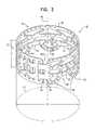
- FIG. 2is a schematic illustration of a structural member of an extra-vascular ring of the endovascular stent-graft system of FIG. 1 , in accordance with an application of the present invention
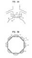
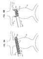
- FIGS. 3A-Bare schematic illustrations of the extra-vascular ring of FIG. 2 deployed around a neck of an aneurysmal aorta, in accordance with an application of the present invention
- FIGS. 3C-Dare schematic illustrations of another extra-vascular ring deployed around a neck of an aneurysmal aorta, in accordance with an application of the present invention.
- FIGS. 4A-Bare schematic illustrations of an extra-vascular ring deployed around a neck of an aneurysmal aorta, as known in the prior art;
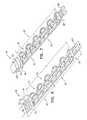
- FIG. 5is a schematic illustration of a structural member of the extra-vascular ring of FIG. 2 in a planar unrolled state, in accordance with an application of the present invention
- FIG. 6is a schematic illustration of another configuration of the structural member of the extra-vascular ring of FIG. 2 in the planar unrolled state, in accordance with an application of the present invention
- FIG. 7is a schematic illustration of yet another configuration of the structural member of the extra-vascular ring of FIG. 2 in the planar unrolled state, in accordance with an application of the present invention
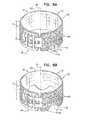
- FIGS. 8A-Bare schematic illustrations of two additional configurations of the extra-vascular ring of FIG. 2 , in accordance with respective applications of the present invention.
- FIGS. 9A-Dare schematic illustrations of a delivery system and method for delivering the extra-vascular ring of FIG. 2 around an aorta, in accordance with an application of the present invention.
- FIG. 1is a schematic illustration of an endovascular stent-graft system 10 , in accordance with an application of the present invention.
- System 10comprises an extra-vascular ring 12 and, for some applications, an endovascular stent-graft 14 .
- extra-vascular ring 12When deployed around a neck 16 of an aneurysmal aorta 20 , extra-vascular ring 12 creates a generally cylindrical landing zone for endovascular stent-graft 14 (which optionally is bifurcated, as shown).
- extra-vascular ring 12When deployed around a neck 16 of an aneurysmal aorta 20 , extra-vascular ring 12 creates a generally cylindrical landing zone for endovascular stent-graft 14 (which optionally is bifurcated, as shown).
- FIG. 1is a schematic illustration of an endovascular stent-graft system 10 , in accordance with an application of the present invention.
- System 10comprises an extra-vascular ring 12 and, for some applications
- endovascular stent-graft 14is endovascularly deployed in aorta 20 , spanning an aneurysm 22 thereof, such that a portion (e.g., a superior distal portion) of endovascular stent-graft 14 is positioned against an internal wall of aorta 20 at the landing zone provided by the extra-vascular ring.
- the landing zonehelps create a non-leaking seal between the stent-graft and the wall of the aorta.
- Extra-vascular ring 12thus helps secure the aneurismal neck from widening and/or leaking. Typically, the landing zone is generally resistant to dilation.
- Extra-vascular ring 12comprises a structural member 30 and, optionally, a textile member 402 , such as described hereinbelow with reference to FIGS. 8A-B .
- FIG. 2is a schematic illustration of structural member 30 of extra-vascular ring 12 , in accordance with an application of the present invention.
- Structural member 30is configured to assume an elongate hollow shape 32 , as shown in FIG. 2 , which, for example, may be generally cylindrical.
- Elongate hollow shape 32is suitable for placement at least partially around aorta 20 so as to provide the landing zone.
- Elongate hollow shape 32has first and second longitudinal ends 40 and 42 .
- Extra-vascular ring 12is configured to be placed around aorta 20 oriented with first longitudinal end 40 inferior to second longitudinal end 42 , typically with first longitudinal end 40 positioned at an inferior end of neck 16 and second longitudinal end 42 positioned at a superior end of neck 16 .
- At least first longitudinal end 40 of structural member 30has a profile that defines a series of curved portions and has no singularities or discontinuities, which profile extends around at least 50% of first longitudinal end 40 (i.e., along at least 50% of a length L 1 of first longitudinal end 40 measured around elongate hollow shape 32 ), such as at least 75%, or 100%.
- the curved portionsrise and fall with respect to a direction that is parallel to a longitudinal axis 48 defined by the elongate hollow shape 32 . Equivalently, if structural member 30 is unrolled to a planar shape 82 , such as described hereinbelow with reference to FIGS.
- first longitudinal end 40one side of planar shape 82 is defined by first longitudinal end 40 , and at least first longitudinal end 40 has the profile that defines the series of curved portions and has no singularities or discontinuities, and the profile extends along at least 50% of first longitudinal end 40 , such as at least 75%, or 100%.
- the profileextends around or along (depending on whether the structural member is rolled or unrolled) less than 100% of first longitudinal end 40 , the profile is provided along two or more portions that are non-contiguous around or along the first longitudinal end.
- the profilemay be provided along two portions that are non-contiguous with each other, each of which extends around or along between 20% and 40% of first longitudinal end 40 .
- the corrugate profileis provided on a single contiguous portion around or along a portion of the first longitudinal end.
- any portions of first longitudinal end 40 along which the profile is not providedare not shaped to have any singularities, discontinuities, or sharp changes in direction, e.g., are straight if structural member 30 is unrolled to planar shape 82 , such as described hereinbelow with reference to FIGS. 5-7 .
- the profileis a corrugated profile that defines a series of smooth undulations 46 .
- corrugatedmeans having any shape comprising a series of smooth undulations that have no singularities, discontinuities, or sharp changes in direction. Therefore, the corrugated profile does not include any sharp, and thus traumatic, features.
- the term “corrugated”does not include within its scope sawtooth and square-wave forms.
- the corrugated profileis provided along first longitudinal end 40 as described in the previous paragraph.
- the corrugated profilehas a substantially sinusoidal form (which includes the series of curved portions).
- at least first longitudinal end 40 of structural member 30has a waved profile.
- first and second longitudinal ends 40 and 42are curved at least partially around longitudinal axis 48 .
- Smooth undulations 46 of first longitudinal end 40are shaped so as to define alternating curved peaks 50 and curved valleys 52 .
- Peaks 50extend in a direction away from second longitudinal end 42 .
- each of the smooth undulationsis shaped so as to define exactly one of curved peaks 50 adjacent to exactly one of curved valleys 52 .
- the corrugated profileis shaped so as to define at least 3, no more than 10, and/or between 3 and 10 undulations 46 , each of which undulations is shaped so as to define exactly one curved peak 50 and exactly one curved valley 52 .
- curved peaks 50do not include any straight portions.
- curved valleys 52do not include any straight portions.
- curved peaks 50are not sharp or traumatic; for example, they may have a radius of curvature R C equal to at least 1.5% (e.g., at least 3%) of length L 1 of first longitudinal end 40 measured around longitudinal axis 48 , when structural member 30 is in a relaxed state (radius of curvature R C is measured along the outer surface of the curved peak, as indicated in FIG. 2 ).
- Length L 1is circumferential, i.e., curved, when structural member 30 has elongate hollow shape 32 , as shown in FIG. 2 .
- the lengthis also labeled in FIG.
- length L 1is at least 30 mm, no more than 120 mm, and/or between 30 and 120 mm, such as 85 mm.
- length L 1may be 80 mm, in which case radius of curvature R C may be at least 1.27 mm.
- elongate hollow shape 32has a longitudinal length (measured parallel to longitudinal axis 48 ) of at least 10 mm, no more than 40 mm, and/or between 10 and 40 mm, such as 15 mm.
- Elongate hollow shape 32has an inner diameter D suitable for surrounding a vessel, such as an aorta, e.g., a descending aorta, such as for treating an aortic aneurysm, i.e., large enough to surround the aorta at the point of attachment of extra-vascular ring 12 and small enough such that upon closure, the inner surface of the elongate hollow shape 32 (which may be cylindrical, as mentioned above) makes direct or indirect contact at least partially with the outer surface of the aorta being treated.
- extra-vascular ring 12further comprises a textile member 402 , such as described hereinbelow with reference to FIGS.
- elongate hollow shape 32makes indirect contact at least partially with the outer surface of the aorta being treated, via the textile member.
- inner diameter Dmay be at least 2 cm, no more than 4 cm, and/or between 2 and 4 cm.
- radius of curvature R C of curved peaks 50is equal to at least 5% (e.g., at least 10%) of inner diameter D when ring 12 is placed around neck 16 .
- FIGS. 3A-Bare schematic illustrations of extra-vascular ring 12 deployed around neck 16 of aneurysmal aorta 20 , in accordance with an application of the present invention.
- FIG. 3Bis a cross-sectional view of ring 12 and aorta 20 along line IIIB-IIIB of FIG. 3A .
- the corrugated profile of longitudinal end 40serves to evenly distribute the pressures and stresses on the partially-dilated tissue of neck 16 , in particular on the section of the aorta in the vicinity of longitudinal end 40 of ring 12 .
- the corrugated profileserves to homogeneously distribute the strain on the aortic tissue at the first longitudinal end of the ring. As can be seen in FIGS.
- the corrugated profileeffectively diffuses the strain on the aortic wall.
- the corrugated profileprovides spaces into which the excess circumference of the aorta can expand, rather than folding inwardly as described hereinbelow with reference to FIGS. 4A-B .
- FIGS. 3C-Dare schematic illustrations of an extra-vascular ring 112 deployed around neck 16 of aneurysmal aorta 20 , in accordance with an application of the present invention.
- FIG. 3Dis a cross-sectional view of ring 112 and aorta 20 along line IIID-IIID of FIG. 3C .
- extra-vascular ring 112is generally similar to extra-vascular ring 12 described hereinabove and hereinbelow, and may include any of the features of extra-vascular ring 12 described hereinabove and/or hereinbelow.
- the profile of first longitudinal end 40 of extra-vascular ring 112includes the series of curved portions interspersed with one or more straight portions 114 .
- the profiledoes not have any sharp changes in direction.
- one or more peaks of the undulationsmay be shaped so as to define a straight portion 114 A, and/or one or more valleys of the undulations may be shaped so as to define a straight portion 114 B.
- the profile of first longitudinal end 40 of extra-vascular ring 112is not a square-wave form, because there are no sharp changes in direction, such as right angles, in the profile.
- the profile of longitudinal end 40serves to minimize the pressures and stresses on the tissue of the aorta, in particular on the section of the aorta in the vicinity of longitudinal end 40 of ring 112 .
- the profileserves to homogeneously diffuse the strain on the aortic tissue at the longitudinal ends of the ring. As can be seen in FIGS. 3C-D , the profile effectively diffuses the strain on the aortic wall.
- the profileprovides spaces into which the excess circumference of the aorta can expand, rather than folding inwardly as described hereinbelow with reference to FIGS. 4A-B .
- FIGS. 4A-Bare schematic illustrations of an extra-vascular ring 70 deployed around neck 16 of aneurysmal aorta 20 , as known in the prior art.
- FIG. 4Bis a cross-sectional view of ring 70 and aorta 20 along line IVB-IVB of FIG. 4A .
- Both longitudinal ends 72 and 74 of ring 70have a straight profile, as known in the prior art.
- this straincan lead to collapse or deformation of part of the aortic wall, which may result, for example, in one or more portions 80 of the wall folding inwardly.
- FIG. 5is a schematic illustration of structural member 30 of extra-vascular ring 12 in a planar unrolled state, in accordance with an application of the present invention.
- Extra-vascular ring 12is shown in a relaxed state in FIG. 5 .
- extra-vascular ring 12is configured to transition between the open planar unrolled state shown in FIG. 5 (or the other configurations described hereinbelow with reference to FIG. 6 or 7 ), and the rolled state shown in FIGS. 1, 2, and 3A -B.
- extra-vascular ring 12is placed in the planar unrolled state for delivery in a catheter to the extra-aortic site, such as described hereinbelow with reference to FIG. 9A , and transitions (typically, automatically) to the rolled state around the aorta upon being deployed from the catheter, such as described hereinbelow with reference to FIGS. 9B-C .
- Structural member 30 of ring 12comprises a material suitable for use in treatment of aortic aneurysms and that is capable of being transitioned between an open planar state and a rolled state.
- structural member 30comprises a shape-memory material or a superelastic material.
- the shape-memory materialmay comprise a nickel-titanium alloy such as Nitinol, (which is also super-elastic over a defined temperature range).
- structural member 30is configured to assume the rolled, elongate hollow shape when in a relaxed state.
- structural member 30while in its open planar state is rolled into a ring (such as shown in FIG. 2 ) of a desired diameter and then heated to fix its dimensions (optionally, the structural member is quickly quenched, e.g., in water, to prevent aging effects).
- structural member 30comprises another material with properties that make it suitable for treatment of aortic aneurysm.
- propertiesinclude biocompatibility, tensile strength, flexibility, and workability.
- the structural membercomprises one or more of these materials (e.g., a biocompatible polymer), and is introduced into the patient by rolling the structural member into a cylinder of small enough diameter to enable introduction by laparoscopic methods, unrolling it in situ, wrapping it around the aorta, and securing it, such as using any of the methods described hereinbelow.
- structural member 30comprises a plurality of stent struts 80 .
- the stent strutshave a thickness of between 0.1 and 1 mm, such as 0.30 mm.
- one side 90 of the planar shapeis defined by first longitudinal end 40 of structural member 30
- another side 92 of the planar shapeis defined by second longitudinal end 42 of structural member 30 .
- length L 1 of side 90(corresponding to first longitudinal end 40 ) varies by less than 20% (e.g., less than 10%) if the structural member, while having planar shape 82 , is longitudinally stretched from a relaxed state by application of a greatest force that is insufficient to cause plastic deformation of the structural member. (Application of a force greater than this greatest force will result in plastic deformation of the structural member, in which case the length might increase substantially before breaking.)
- structural member 30is configured to generally not be longitudinally expansible when it has planar shape 82 , and accordingly not to be radially expansible when it has elongate hollow shape 32 .
- Alternating curved peaks 50 and curved valleys 52 of the corrugated profile of longitudinal end 40are not configured to compress or stretch in a direction parallel to longitudinal end 40 .
- undulations 46 of the corrugated profileare disposed about a straight line when the structural member has planar shape 82 ; the direction is parallel to this line; the term “parallel” should also be understood in this way hereinbelow and in the claims.
- radius of curvature R C of curved peaks 50changes by less than 10% (e.g., less than 5%) if the structural member, while having planar shape 82 , is longitudinally stretched from a relaxed state by application of a greatest force that is insufficient to cause plastic deformation of the structural member.
- curved peaks 50are not configured to bend or flex when the structural member is longitudinal stretched.
- At least one 84 of stent struts 80extends completely alongside at least two of undulations 46 (i.e., two of curved peaks 50 and two of curved valleys 52 ), such that strut 84 substantially prevents longitudinal stretching of the at least two of the undulations.
- strut 84has a length L 3 , measured in a direction parallel to side 90 , equal to at least 90% of length L 1 of side 90 , such as equal to length L 1 .
- a plurality of stent struts 80extend completely alongside at least two of undulations 46 , such as two of stent struts 80 , or three of stent struts 80 , as labeled struts 84 , 86 , and 88 in FIG. 5 .
- stent strut 84geometrically encompasses at least one straight line segment 94 that is parallel to side 90 and extends completely alongside the at least two of undulations 46 , when structural member 30 has planar shape 82 .
- strut 84is shaped such that a straight line segment could be drawn on the strut completely alongside the at least two of undulations 46 .
- straight line segment 94is an abstract geometric construct provided for purposes of describing the shape of strut 84 , rather than a physical element of structural member 30 , and thus is typically not actually drawn on the structural member.
- stent strut 84is straight when structural member 30 is unrolled to planar shape 82 .
- planar shape 82 of extra-vascular ring 12is generally rectangular, with two substantially parallel short sides 96 and 98 and two long sides 90 and 92 , each of which is substantially perpendicular to the short sides.
- side 92i.e., the side not shown as corrugated
- both long sides 90 and 92have respective corrugated profiles along at least 50% of their respective lengths, such as along at least 75%, e.g., 100%, of their respective lengths (configuration not shown).
- planar shape 82has rounded corners, as shown in FIG. 5 (and FIGS. 6 and 7 ).
- edges of stent struts 80are at least partially rounded smooth, such as by chemical erosion or electro-chemical erosion, as is known in the stent art. For clarity of illustration, this rounding is not shown in FIG. 5 (or FIGS. 2, 6, 7, and 8A -B).
- longitudinal axis 48is substantially parallel to short sides 96 and 98 of structural member 30 , and long sides 90 and 92 form upper and lower faces of elongate hollow shape 32 ; for applications in which elongate hollow shape 32 is cylindrical, the long sides form the (open) circular upper and lower faces of the cylinder.
- the corrugated profileis transverse to longitudinal axis 48 when structural member 30 is in its rolled state. As described below, the ring is brought to its final diameter after its insertion into the patient's body.
- stent struts 80are shaped so as to define a plurality of missing portions of structural member 30 , i.e., openings through structural member 30 .
- structural member 30is shaped so as to define an outer substantially contiguous border 105 , which may, for example have a width of about 1.50 ⁇ 0.05 mm.
- border 105is recessed by two rounded portions 115 , and may be narrower than the remainder of the border (e.g., 0.7 mm in width).
- a central portion of structural memberis shaped so as to define a plurality of missing portions 130 , two sides of which missing portions are substantially parallel to long side 92 .
- a blow-up in FIG. 5shows a detailed view of the edge of one of these missing portions 130 , including a separating stent strut 135 between them (in the configuration shown, this separating stent strut is curved and has a typical width of about 0.7 mm).
- structural member 30is shaped so as to define missing portions 140 along long side 90 (which has the profile), between undulations 46 and stent strut 84 (described above).
- structural member 30is shaped so as to define two missing portions 150 nearest short sides 96 and 98 , each of which may have the shape of a rectangle truncated by a curve along the side nearest first missing portion 140 .
- Detailed views of missing portions 140 and 150are shown in respective blow-ups in FIG. 5 , in accordance with respective applications of the present invention.
- structural member 30is shaped so as to define a series of triangular missing portions 160 with one side parallel to long side 92 and having alternating orientations, between central missing portions 130 and the inside of border 105 (e.g, between struts 86 and 88 , described hereinabove).
- structural member 30is shaped so as to define a plurality of small (e.g., circular) missing portions 170 , which may, for example have a typical diameter of 0.5+/ ⁇ 0.1 mm.
- missing portions 170are located on all areas of the structural member at which the material has a width sufficient to support these missing portions.
- missing portions 170are substantially centered with respect to the width of stent struts 80 .
- the missing portions described aboveserve one or more of four purposes.
- the missing portionsmay reduce the weight of structural member 30 .
- the missing portionsmay reduce the amount of material needed to construct structural member 30 .
- the missing portionsmay allow free tissue ingrowth therethrough.
- the missing portionsmay be arranged to enhance flexibility of the structural member. It is to be understood that the particular arrangement of missing portions 130 and 170 are shown in the figures by way of example and not limitation, and that other arrangements that achieve the same or similar purposes will be apparent to those skilled in the art who have read the present application, and are within the scope of the present invention.
- FIG. 6is a schematic illustration of another configuration of structural member 30 of extra-vascular ring 12 in the planar unrolled state, in accordance with an application of the present invention.
- structural member 30comprises, in addition to the elements described above with reference to FIGS. 1, 2, 3A -B, and 5 , a tab 200 at one of short sides 96 and 98 , and an extension 210 at the other one of short sides 96 and 98 .
- Extension 210is shaped so as to define a plurality of slots 220 .
- an overall length L 4 of structural member 30including tab 200 and extension 210 is at least 30 mm, no more than 150 mm, and/or between 30 and 150 mm, such as about 108 mm; for example, the tab may add about 13 mm to the length of the structural member, and the extension may add about 10 to 20 mm.
- a width W 1 of the tabis about 8.75 mm
- a width W 2 of slots 220is about 12 mm
- a height H of the slotsis about 1.5 mm.
- FIG. 7is a schematic illustration of yet another configuration of structural member 30 of extra-vascular ring 12 in the planar unrolled state, in accordance with an application of the present invention.
- structural member 30comprises a tab-and-slot assembly, which includes a tab 300 and an extension 310 .
- Extension 310is shaped so as to define slots 320 that include respective flexible flaps 322 that aid in securing tab 300 when the ring is closed.
- the overall dimensions of the configuration of FIG. 7are substantially the same as those of the configuration of FIG. 6 . (Length L 1 of first longitudinal end 40 is to be understood herein, including in the claims, as excluding the length of tab 300 and the length of extension 310 .)
- gap 400typically extends longitudinally along an entire longitudinal length of elongate hollow shape 32 from first longitudinal end 40 to second longitudinal end 42 . Short sides 96 and 98 are not brought into contact with each other, and the ring is not otherwise closed, until the ring has been put in place around the patient's aorta.
- the final closure of the ring(which closes gap 400 ) is effected after the ring has been put into place around the patient's aorta.
- the closureis effected by inserting tab 200 into slots 220
- the closureis effected by inserting tab 300 into slots 320 .
- Structural member 30may be made by any method known in the art.
- the structural membermay be fabricated from a rectangular blank by removing the missing portions by any standard means such as punching, stamping, milling, or laser cutting.
- the curved corners, if provided, and the profile of at least first longitudinal end 40may produced by any standard means such as cutting or stamping.
- the structural membermay be cast or molded on a form.
- Extra-vascular ring 12may implement either of these configurations in combination with any of the configurations described hereinabove, including with reference to FIGS. 2, 5, 6, and 7 .
- extra-vascular ring 12further comprises a textile member 402 , securely attached to and at least partially covering structural member 30 (typically an inner surface of the ring).
- Textile member 402comprises an implantable-grade, biologically-compatible fabric, and may comprise, for example, a polyester, a polyethylene (e.g., a poly-ethylene-terephthalate), a polypropylene mesh, a polymeric film material (e.g., polytetrafluoroethylene), a polymeric textile material (e.g., woven polyethylene terephthalate (PET)), natural tissue graft (e.g., saphenous vein or collagen), or a combination thereof.
- textile member 402comprises a macroporous medical textile member mention, such as described in US Patent Application Publication 2010/0292774 to Shalev, which is assigned to the assignee of the present application and is incorporated herein by reference.
- extra-vascular ring 12comprises an external microporous layer, such as described in the '774 publication.
- textile member 402is shaped so as to define portions 404 that extend between adjacent curved peaks 50 .
- Portions 404are configured to provide sufficient slack to allow the excess circumference to expand into the spaces provided by the corrugated profile, as described hereinabove with reference to FIGS. 3A-B .
- textile member 402does not define portions 404 , but rather is shaped so as to provide open areas between adjacent curved peaks 50 .
- the edge of the textile membermay coincide with and have the same shape as the corrugated profile; in this configuration, a first longitudinal end of extra-vascular ring 12 coincides with first longitudinal end 40 of structural member 30 , such that the first longitudinal end of extra-vascular ring 12 has the profile that defines the series of curved portions and has no singularities or discontinuities, e.g., the corrugated profile.
- the textile membermay partially extend between adjacent curved peaks 50 (configuration not shown).
- FIGS. 9A-Dare schematic illustrations of a delivery system 410 and method for delivering extra-vascular ring 12 around aorta 20 , in accordance with an application of the present invention.
- Delivery system 10may be used for delivering extra-vascular ring 12 around aorta 20 (as shown) or other tissue, such as an organ, e.g., as a tubular organ, e.g., another blood vessel or a nerve.
- Delivery system 410comprises a catheter 430 , which comprises an outer pull-back shaft 432 having generally rectangular cross sections. The outer pull-back shaft serves as a delivery shaft.
- Extra-vascular ring 12is initially removably disposed within outer pull-back shaft 432 , with the extra-vascular ring in a deformed generally planar state, as shown in FIG. 5, 6 , or 7 .
- extra-vascular ring 12is in a rolled state when initially disposed within the outer pull-back shaft (configuration not shown), in which case outer pull-back shaft 432 typically does not have generally rectangular cross sections.
- a surgeoncreates a working channel, typically laparoscopically or hand-assisted laparoscopically, to an external surface of a portion of a target organ, such as aorta 20 , e.g., neck 16 of an aneurysmal aorta, such as a sub-renal neck 16 immediately inferior (e.g., caudally adjacent) to the renal arteries, as shown in FIGS. 9A-D , or a supra-renal neck, an ascending aortic neck, or a neck adjacent the right subclavian artery (locations not shown).
- a target organsuch as aorta 20
- neck 16 of an aneurysmal aortasuch as a sub-renal neck 16 immediately inferior (e.g., caudally adjacent) to the renal arteries, as shown in FIGS. 9A-D , or a supra-renal neck, an ascending aortic neck, or a neck adjacent the right subclavian artery (
- the surgeonadvances a distal portion of delivery system 410 to the target organ, such as aorta 20 , as shown in FIG. 9A .
- the surgeonadvances a distal end 436 of outer pull-back shaft 432 slightly beyond the far side of the aorta, such that that outer pull-back shaft 432 is tangential to the aorta, as shown in FIG. 9A .
- the surgeonsubsequently proximally withdraws pull-back shaft 432 , while simultaneously preventing proximal movement of extra-vascular ring 12 using a stopper shaft.
- the stopper shaftis not shown in FIG. 9B ; the stopper shaft may be implemented using techniques described in PCT Application PCT/IL2012/000083, filed Feb. 16, 2012, entitled, “Vascular bands and delivery systems therefor,” which published as PCT Publication WO 2012/111006, is assigned to the assignee of the present application and is incorporated herein by reference, with reference to FIGS. 3A-14C thereof.
- the extra-vascular ringis configured to assume a curved shape upon deployment, and thus wraps around the organ, e.g., the aorta, as the ring is deployed, as shown in FIG. 9B .
- the ringis self-curling, and, to this end, typically comprises a shape memory material, such as a super-elastic metal, e.g., Nitinol, which is heat-set to assume the curled configuration, e.g., a circularly-, helically-, or spirally-bent configuration.
- structural member 30is configured to automatically transition from the deformed state to a relaxed state as the structural member is deployed from pull-back shaft 432 .
- FIG. 9Cshows pull-back shaft 432 and extra-vascular ring 12 after the ring has been fully deployed from the shaft.
- the ringencircles at least a portion of the organ, e.g., the aorta, such as only a portion of or the entire organ.
- the surgeonhas oriented ring 12 such that first longitudinal end 40 is inferior to second longitudinal end 42 , with first longitudinal end 40 positioned at an inferior end of neck 16 and second longitudinal end 42 positioned at a superior end of neck 16 .
- extra-vascular ring 12When deployed around neck 16 of an aneurysmal aorta, extra-vascular ring 12 creates a landing zone for endovascular stent-graft 14 (which optionally is bifurcated, as shown). As shown in FIG. 9D , endovascular stent-graft 40 is deployed in the aorta, spanning an aneurysm 22 thereof. A distal portion of the stent-graft is positioned against the internal wall of the aorta at the landing zone. The landing zone provided by extra-vascular ring 12 helps create a non-leaking seal between the stent-graft and the wall of the aorta. Extra-vascular ring 12 thus helps secure aneurismal neck 16 from widening and/or leaking.
- intra-vascular ring 12is secured or otherwise attached (optionally, reversibly) to intravascular stent-graft 14 , in order to prevent dislocation of the ring and the intravascular stent-graft along the aor
- endovascular stent-graft 14is implanted first, and subsequently extra-vascular ring 12 is placed around the aorta.
- elongate hollow shape 32 of extra-vascular ring 12subtends an arc of less than 360 degrees, i.e., does not fully surround the aorta.
- the elongate hollow shapeis circumferentially complete upon placement around the aorta.
- a method for treating an aortic aneurysmcomprises (a) identifying a subject having an aneurysm of the abdominal aorta; (b) providing extra-vascular ring 12 in any of the configurations described herein; and (c) positioning the ring around the aorta, inferior to the renal arteries, optionally laparoscopically.
- the ringis compressed to a deformed state during delivery and positioning.
- the methodmay further comprise providing intravascular stent-graft 14 , and placing the intravascular stent-graft into the aneurysmatic aorta in the subject, optionally laparoscopically.
- identifying the subject having the aneurysm of the abdominal aortacomprises identifying the subject having the aneurysm of the abdominal aorta that is likely to rupture. For some applications, identifying the subject having the aneurysm of the abdominal aorta that is likely to rupture defining an aneurysm of the abdominal aorta that is likely to rupture as an aneurysm that is located within about 2 cm of a renal artery, and determining that the abdominal aneurysm is within about 2 cm of a renal artery of the subject.
- the ringis closed using a closure assembly that comprises one or more fastening elements, such as tab 200 and extension 210 , described hereinabove with reference to FIG. 6 , or tab 300 and extension 310 , described hereinabove with reference to FIG. 7 .
- the ringmay be closed using other fastening techniques.
- the ringmay be closed using fastening elements selected from the group consisting of: threads, screws, hooks, zips, fasteners, clips, flaps, claspers, springs, claspers, staplers, grips, zippers, hooks and corresponding eyes, hook and loop reclosable fastener squares, hook and loop reclosable fastener strips, hook and loop reclosable fastener dots, hook-and-loop fasteners such as Velcro-type fasteners, straps, holes and string, sutures, wires, cables, tabs, poppers, nails, buttons and corresponding button holes, press button brackets, glues, adhesives, or any combination thereof.
- fastening elementsselected from the group consisting of: threads, screws, hooks, zips, fasteners, clips, flaps, claspers, springs, claspers, staplers, grips, zippers, hooks and corresponding eyes, hook and loop reclosable fastener squares, hook and loop reclosable fastener strips, hook and loop reclosable fast
- tubularmeans having the form of an elongate hollow object that defines a conduit therethrough.
- a “tubular” structuremay have varied cross-sections therealong, and the cross-sections are not necessarily circular.
- one or more of the cross-sectionsmay be generally circular, or generally elliptical but not circular, or circular.
- polygonal figurese.g., triangles or rectangles
- trianglesare to be understood as including substantially polygonal figures with rounded corners and/or substantially polygonal figures bounded by curves other than straight lines.
- triangleincludes shapes such as those of the triangular portions 160 , described hereinabove with reference to FIG. 5 , which have rounded corners.
- references to geometric shapes in terms of their ideal geometryare not intended to limit the invention to the ideal geometry, but may include deviations from the ideal geometry that are produced when the invention is used in practice.
- rolling a rectangle so that two opposite sides meetwill form a cylinder.
- the rolling of a substantially rectangular piece into a substantially cylindrical ringmay be treated as if the piece and the ring are ideal geometric figures.
- the scope of the inventionhowever includes cases where in practice the substantially cylindrical ring thus formed is oblique, such as because of imperfections in manufacturing or errors by the surgeon.
Landscapes
- Health & Medical Sciences (AREA)
- Engineering & Computer Science (AREA)
- Biomedical Technology (AREA)
- Cardiology (AREA)
- Oral & Maxillofacial Surgery (AREA)
- Transplantation (AREA)
- Heart & Thoracic Surgery (AREA)
- Vascular Medicine (AREA)
- Life Sciences & Earth Sciences (AREA)
- Animal Behavior & Ethology (AREA)
- General Health & Medical Sciences (AREA)
- Public Health (AREA)
- Veterinary Medicine (AREA)
- Gastroenterology & Hepatology (AREA)
- Pulmonology (AREA)
- Prostheses (AREA)
Abstract
Description
- PCT Application PCT/IL2008/000287, filed Mar. 5, 2008, which published as PCT Publication WO 2008/107885 to Shalev et al., and U.S. application Ser. No. 12/529,936 in the national stage thereof, which published as US Patent Application Publication 2010/0063575 to Shalev et al.
U.S. Provisional Application 60/892,885, filed Mar. 5, 2007- PCT Application PCT/IL2007/001312, filed Oct. 29, 2007, which published as PCT Publication WO/2008/053469 to Shalev, and U.S. application Ser. No. 12/447,684 in the national stage thereof, which published as US Patent Application Publication 2010/0070019 to Shalev
U.S. Provisional Application 60/991,726, filed Dec. 2, 2007- PCT Application PCT/IL2008/001621, filed Dec. 15, 2008, which published as PCT Publication WO 2009/078010, and U.S. application Ser. No. 12/808,037 in the national stage thereof, which published as US Patent Application Publication 2010/0292774
- U.S. Provisional Application 61/219,758, filed Jun. 23, 2009
- U.S. Provisional Application 61/221,074, filed Jun. 28, 2009
- PCT Application PCT/IB2010/052861, filed Jun. 23, 2010, which published as PCT Publication WO 2010/150208, and U.S application Ser. No. 13/380,278 in the national stage thereof, which issued as U.S Pat. No. 8,870,938
- PCT Application PCT/IL2010/000549, filed Jul. 8, 2010, which published as PCT Publication WO 2011/004374
- PCT Application PCT/IL2010/000564, filed Jul. 14, 2010, which published as PCT Publication WO 2011/007354, and U.S application Ser. No. 13/384,075 in the national stage thereof, which published as U.S Patent Application Publication 2012/0179236
- PCT Application PCT/IL2010/000917, filed Nov. 4, 2010, which published as PCT Publication WO 2011/055364
- PCT Application PCT/IL2010/000999, filed Nov. 30, 2010, which published as PCT Publication WO 2011/064782
- PCT Application PCT/IL2010/001018, filed Dec. 2, 2010, which published as PCT Publication WO 2011/067764
- PCT Application PCT/IL2010/001037, filed Dec. 8, 2010, which published as PCT Publication WO 2011/070576
- PCT Application PCT/IL2010/001087, filed Dec. 27, 2010, which published as PCT Publication WO 2011/080738
- PCT Application PCT/IL2011/000135, filed Feb. 8, 2011, which published as PCT Publication WO 2011/095979
- PCT Application PCT/IL2011/000801, filed Oct. 10, 2011, which published as PCT Publication WO 2012/049679
- U.S. application Ser. No. 13/031,871, filed Feb. 22, 2011, which published as US Patent Application Publication 2011/0208289
- PCT Application PCT/IL2012/000083, filed Feb. 16, 2012, which published as PCT Publication WO 2012/111006.
Claims (21)
Priority Applications (1)
| Application Number | Priority Date | Filing Date | Title |
|---|---|---|---|
| US14/001,641US9486341B2 (en) | 2011-03-02 | 2012-03-01 | Reduced-strain extra-vascular ring for treating aortic aneurysm |
Applications Claiming Priority (3)
| Application Number | Priority Date | Filing Date | Title |
|---|---|---|---|
| US201161448199P | 2011-03-02 | 2011-03-02 | |
| PCT/IL2012/000095WO2012117395A1 (en) | 2011-03-02 | 2012-03-01 | Reduced-strain extra- vascular ring for treating aortic aneurysm |
| US14/001,641US9486341B2 (en) | 2011-03-02 | 2012-03-01 | Reduced-strain extra-vascular ring for treating aortic aneurysm |
Publications (2)
| Publication Number | Publication Date |
|---|---|
| US20140052236A1 US20140052236A1 (en) | 2014-02-20 |
| US9486341B2true US9486341B2 (en) | 2016-11-08 |
Family
ID=46757407
Family Applications (1)
| Application Number | Title | Priority Date | Filing Date |
|---|---|---|---|
| US14/001,641Expired - Fee RelatedUS9486341B2 (en) | 2011-03-02 | 2012-03-01 | Reduced-strain extra-vascular ring for treating aortic aneurysm |
Country Status (3)
| Country | Link |
|---|---|
| US (1) | US9486341B2 (en) |
| EP (1) | EP2680788A4 (en) |
| WO (1) | WO2012117395A1 (en) |
Cited By (2)
| Publication number | Priority date | Publication date | Assignee | Title |
|---|---|---|---|---|
| US10888414B2 (en) | 2019-03-20 | 2021-01-12 | inQB8 Medical Technologies, LLC | Aortic dissection implant |
| WO2022076686A1 (en) | 2020-10-07 | 2022-04-14 | Canary Medical Switzerland Ag | Providing medical devices with sensing functionality |
Families Citing this family (21)
| Publication number | Priority date | Publication date | Assignee | Title |
|---|---|---|---|---|
| CA3009244C (en) | 2009-06-23 | 2020-04-28 | Endospan Ltd. | Vascular prostheses for treating aneurysms |
| US9468517B2 (en) | 2010-02-08 | 2016-10-18 | Endospan Ltd. | Thermal energy application for prevention and management of endoleaks in stent-grafts |
| CA2826022A1 (en) | 2011-02-03 | 2012-08-09 | Endospan Ltd. | Implantable medical devices constructed of shape memory material |
| WO2012111006A1 (en) | 2011-02-17 | 2012-08-23 | Endospan Ltd. | Vascular bands and delivery systems therefor |
| WO2012117395A1 (en) | 2011-03-02 | 2012-09-07 | Endospan Ltd. | Reduced-strain extra- vascular ring for treating aortic aneurysm |
| US8574287B2 (en) | 2011-06-14 | 2013-11-05 | Endospan Ltd. | Stents incorporating a plurality of strain-distribution locations |
| US8951298B2 (en) | 2011-06-21 | 2015-02-10 | Endospan Ltd. | Endovascular system with circumferentially-overlapping stent-grafts |
| US9254209B2 (en) | 2011-07-07 | 2016-02-09 | Endospan Ltd. | Stent fixation with reduced plastic deformation |
| US9839510B2 (en) | 2011-08-28 | 2017-12-12 | Endospan Ltd. | Stent-grafts with post-deployment variable radial displacement |
| US9427339B2 (en) | 2011-10-30 | 2016-08-30 | Endospan Ltd. | Triple-collar stent-graft |
| US9597204B2 (en) | 2011-12-04 | 2017-03-21 | Endospan Ltd. | Branched stent-graft system |
| WO2013171730A1 (en) | 2012-05-15 | 2013-11-21 | Endospan Ltd. | Stent-graft with fixation elements that are radially confined for delivery |
| US9993360B2 (en) | 2013-01-08 | 2018-06-12 | Endospan Ltd. | Minimization of stent-graft migration during implantation |
| WO2015075708A1 (en) | 2013-11-19 | 2015-05-28 | Endospan Ltd. | Stent system with radial-expansion locking |
| CN106029005B (en) | 2014-12-18 | 2018-01-19 | 恩都思潘有限公司 | The Endovascular stent-graft of horizontal conduit with tired resistance |
| WO2016113731A1 (en) | 2015-01-12 | 2016-07-21 | Endospan Ltd. | Self-curving stent-graft |
| WO2016125137A1 (en) | 2015-02-02 | 2016-08-11 | Endospan Ltd. | Self-orienting endovascular delivery system |
| US9687366B2 (en) | 2015-06-19 | 2017-06-27 | Cordis Corporation | Endoleak mitigator for aneurysm stent-graft |
| US20180369003A1 (en)* | 2015-11-11 | 2018-12-27 | Council Of Scientific & Industrial Research | Radially self-expandable rolled up tubular stent |
| WO2017081679A1 (en) | 2015-11-12 | 2017-05-18 | Endospan Ltd. | Stent-grafts systems with skirt |
| JP2020512914A (en) | 2017-03-21 | 2020-04-30 | エンドスパン リミテッド | Stent graft for sealing around external disturbances |
Citations (349)
| Publication number | Priority date | Publication date | Assignee | Title |
|---|---|---|---|---|
| US4355426A (en) | 1975-05-09 | 1982-10-26 | Macgregor David C | Porous flexible vascular graft |
| US4505767A (en) | 1983-10-14 | 1985-03-19 | Raychem Corporation | Nickel/titanium/vanadium shape memory alloy |
| US4562596A (en) | 1984-04-25 | 1986-01-07 | Elliot Kornberg | Aortic graft, device and method for performing an intraluminal abdominal aortic aneurysm repair |
| US4577631A (en) | 1984-11-16 | 1986-03-25 | Kreamer Jeffry W | Aneurysm repair apparatus and method |
| US4617932A (en) | 1984-04-25 | 1986-10-21 | Elliot Kornberg | Device and method for performing an intraluminal abdominal aortic aneurysm repair |
| US4665906A (en) | 1983-10-14 | 1987-05-19 | Raychem Corporation | Medical devices incorporating sim alloy elements |
| US4739762A (en) | 1985-11-07 | 1988-04-26 | Expandable Grafts Partnership | Expandable intraluminal graft, and method and apparatus for implanting an expandable intraluminal graft |
| US4787899A (en) | 1983-12-09 | 1988-11-29 | Lazarus Harrison M | Intraluminal graft device, system and method |
| US4816339A (en) | 1987-04-28 | 1989-03-28 | Baxter International Inc. | Multi-layered poly(tetrafluoroethylene)/elastomer materials useful for in vivo implantation |
| US4878906A (en) | 1986-03-25 | 1989-11-07 | Servetus Partnership | Endoprosthesis for repairing a damaged vessel |
| US4886062A (en) | 1987-10-19 | 1989-12-12 | Medtronic, Inc. | Intravascular radially expandable stent and method of implant |
| US4938740A (en) | 1988-05-25 | 1990-07-03 | Trustees Of The University Of Pennsylvania | Reducing stress at vascular graft anastomoses |
| US4969458A (en) | 1987-07-06 | 1990-11-13 | Medtronic, Inc. | Intracoronary stent and method of simultaneous angioplasty and stent implant |
| US5042707A (en) | 1990-10-16 | 1991-08-27 | Taheri Syde A | Intravascular stapler, and method of operating same |
| US5064435A (en) | 1990-06-28 | 1991-11-12 | Schneider (Usa) Inc. | Self-expanding prosthesis having stable axial length |
| US5104404A (en) | 1989-10-02 | 1992-04-14 | Medtronic, Inc. | Articulated stent |
| US5122136A (en) | 1990-03-13 | 1992-06-16 | The Regents Of The University Of California | Endovascular electrolytically detachable guidewire tip for the electroformation of thrombus in arteries, veins, aneurysms, vascular malformations and arteriovenous fistulas |
| US5133732A (en) | 1987-10-19 | 1992-07-28 | Medtronic, Inc. | Intravascular stent |
| US5234448A (en) | 1992-02-28 | 1993-08-10 | Shadyside Hospital | Method and apparatus for connecting and closing severed blood vessels |
| US5486183A (en) | 1990-10-09 | 1996-01-23 | Raychem Corporation | Device or apparatus for manipulating matter |
| US5507769A (en) | 1994-10-18 | 1996-04-16 | Stentco, Inc. | Method and apparatus for forming an endoluminal bifurcated graft |
| US5509923A (en) | 1989-08-16 | 1996-04-23 | Raychem Corporation | Device for dissecting, grasping, or cutting an object |
| US5522880A (en) | 1990-06-11 | 1996-06-04 | Barone; Hector D. | Method for repairing an abdominal aortic aneurysm |
| US5527322A (en) | 1993-11-08 | 1996-06-18 | Perclose, Inc. | Device and method for suturing of internal puncture sites |
| US5549662A (en) | 1994-11-07 | 1996-08-27 | Scimed Life Systems, Inc. | Expandable stent using sliding members |
| US5554181A (en) | 1994-05-04 | 1996-09-10 | Regents Of The University Of Minnesota | Stent |
| US5556413A (en) | 1994-03-11 | 1996-09-17 | Advanced Cardiovascular Systems, Inc. | Coiled stent with locking ends |
| US5562724A (en) | 1993-12-15 | 1996-10-08 | William Cook Europe A/S | Endovascular graft prosthesis and an implantation method for such a prosthesis |
| US5591229A (en) | 1990-06-11 | 1997-01-07 | Parodi; Juan C. | Aortic graft for repairing an abdominal aortic aneurysm |
| US5607445A (en) | 1992-06-18 | 1997-03-04 | American Biomed, Inc. | Stent for supporting a blood vessel |
| US5613974A (en) | 1992-12-10 | 1997-03-25 | Perclose, Inc. | Apparatus and method for vascular closure |
| US5632746A (en) | 1989-08-16 | 1997-05-27 | Medtronic, Inc. | Device or apparatus for manipulating matter |
| US5632763A (en) | 1995-01-19 | 1997-05-27 | Cordis Corporation | Bifurcated stent and method for implanting same |
| US5632772A (en) | 1993-10-21 | 1997-05-27 | Corvita Corporation | Expandable supportive branched endoluminal grafts |
| US5639278A (en) | 1993-10-21 | 1997-06-17 | Corvita Corporation | Expandable supportive bifurcated endoluminal grafts |
| US5643340A (en) | 1994-10-27 | 1997-07-01 | Nunokawa; Mioko | Synthetic vascular prosthesis |
| US5653743A (en) | 1994-09-09 | 1997-08-05 | Martin; Eric C. | Hypogastric artery bifurcation graft and method of implantation |
| US5676696A (en) | 1995-02-24 | 1997-10-14 | Intervascular, Inc. | Modular bifurcated intraluminal grafts and methods for delivering and assembling same |
| US5676697A (en) | 1996-07-29 | 1997-10-14 | Cardiovascular Dynamics, Inc. | Two-piece, bifurcated intraluminal graft for repair of aneurysm |
| WO1998006355A1 (en) | 1996-08-09 | 1998-02-19 | Edoga John K | Endoluminal graft replacement of abdominal aortic aneurysms |
| US5728134A (en) | 1996-09-17 | 1998-03-17 | Barak; Shlomo | Method and apparatus for hemostasis |
| US5749879A (en) | 1989-08-16 | 1998-05-12 | Medtronic, Inc. | Device or apparatus for manipulating matter |
| US5755774A (en) | 1994-06-27 | 1998-05-26 | Corvita Corporation | Bistable luminal graft endoprosthesis |
| US5755771A (en) | 1994-11-03 | 1998-05-26 | Divysio Solutions Ulc | Expandable stent and method of delivery of same |
| US5755770A (en) | 1995-01-31 | 1998-05-26 | Boston Scientific Corporatiion | Endovascular aortic graft |
| US5755781A (en) | 1996-08-06 | 1998-05-26 | Iowa-India Investments Company Limited | Embodiments of multiple interconnected stents |
| US5755777A (en) | 1991-10-25 | 1998-05-26 | Cook Incorporated | Expandable transluminal graft prosthesis for repair of aneurysm |
| US5769884A (en) | 1996-06-27 | 1998-06-23 | Cordis Corporation | Controlled porosity endovascular implant |
| US5769882A (en) | 1995-09-08 | 1998-06-23 | Medtronic, Inc. | Methods and apparatus for conformably sealing prostheses within body lumens |
| US5782903A (en) | 1987-10-19 | 1998-07-21 | Medtronic, Inc. | Intravascular stent and method |
| US5782906A (en) | 1994-08-25 | 1998-07-21 | Ethicon, Inc. | Combination arterial stent |
| US5824040A (en) | 1995-12-01 | 1998-10-20 | Medtronic, Inc. | Endoluminal prostheses and therapies for highly variable body lumens |
| US5827321A (en) | 1997-02-07 | 1998-10-27 | Cornerstone Devices, Inc. | Non-Foreshortening intraluminal prosthesis |
| US5843170A (en) | 1994-09-02 | 1998-12-01 | Ahn; Sam Seunghae | Apparatus and method for performing aneurysm repair |
| US5855600A (en) | 1997-08-01 | 1999-01-05 | Inflow Dynamics Inc. | Flexible implantable stent with composite design |
| US5876432A (en) | 1994-04-01 | 1999-03-02 | Gore Enterprise Holdings, Inc. | Self-expandable helical intravascular stent and stent-graft |
| US5906641A (en) | 1997-05-27 | 1999-05-25 | Schneider (Usa) Inc | Bifurcated stent graft |
| US5921994A (en) | 1995-06-15 | 1999-07-13 | Perclose, Inc. | Low profile intraluminal suturing device and method |
| WO1999034748A1 (en) | 1998-01-07 | 1999-07-15 | Boston Scientific, Limited | Implantable band and stent graft for treating a vessel aneurysm |
| US5976178A (en) | 1996-11-07 | 1999-11-02 | Vascular Science Inc. | Medical grafting methods |
| US5980552A (en) | 1994-03-17 | 1999-11-09 | Medinol Ltd. | Articulated stent |
| US6015431A (en) | 1996-12-23 | 2000-01-18 | Prograft Medical, Inc. | Endolumenal stent-graft with leak-resistant seal |
| US6033435A (en) | 1997-11-03 | 2000-03-07 | Divysio Solutions Ulc | Bifurcated stent and method for the manufacture and delivery of same |
| US6036725A (en) | 1998-06-10 | 2000-03-14 | General Science And Technology | Expandable endovascular support device |
| US6059824A (en) | 1998-12-23 | 2000-05-09 | Taheri; Syde A. | Mated main and collateral stent and method for treatment of arterial disease |
| US6077298A (en) | 1999-02-20 | 2000-06-20 | Tu; Lily Chen | Expandable/retractable stent and methods thereof |
| US6099497A (en) | 1998-03-05 | 2000-08-08 | Scimed Life Systems, Inc. | Dilatation and stent delivery system for bifurcation lesions |
| US6117145A (en) | 1994-06-01 | 2000-09-12 | Perclose, Inc. | Method and device for providing hemostasis at vascular penetration sites |
| US6152956A (en) | 1997-01-28 | 2000-11-28 | Pierce; George E. | Prosthesis for endovascular repair of abdominal aortic aneurysms |
| US6156064A (en) | 1998-08-14 | 2000-12-05 | Schneider (Usa) Inc | Stent-graft-membrane and method of making the same |
| US6168615B1 (en) | 1998-05-04 | 2001-01-02 | Micrus Corporation | Method and apparatus for occlusion and reinforcement of aneurysms |
| US6200339B1 (en) | 1999-02-23 | 2001-03-13 | Datascope Investment Corp. | Endovascular split-tube bifurcated graft prosthesis and an implantation method for such a prosthesis |
| US20010004705A1 (en) | 1998-03-04 | 2001-06-21 | Killion Douglas P. | Stent having variable properties and method of its use |
| US20010010006A1 (en) | 1997-04-23 | 2001-07-26 | St. Jude Medical Cardiovascular Goup Inc. | Medical grafting connectors and fasteners |
| US6270524B1 (en) | 1996-11-12 | 2001-08-07 | Medtronic, Inc. | Flexible, radially expansible luminal prostheses |
| US20010014823A1 (en) | 1998-03-16 | 2001-08-16 | Teramed, Inc. | Bifurcated prosthetic graft |
| US6290720B1 (en) | 1998-11-16 | 2001-09-18 | Endotex Interventional Systems, Inc. | Stretchable anti-buckling coiled-sheet stent |
| US6296661B1 (en) | 2000-02-01 | 2001-10-02 | Luis A. Davila | Self-expanding stent-graft |
| US6312458B1 (en) | 2000-01-19 | 2001-11-06 | Scimed Life Systems, Inc. | Tubular structure/stent/stent securement member |
| US20010044652A1 (en) | 1999-10-14 | 2001-11-22 | Moore Brian Edward | Stents with multi-layered struts |
| US20010044651A1 (en) | 1998-02-17 | 2001-11-22 | Steinke Thomas A. | Expandable stent with sliding and locking radial elements |
| US20010047198A1 (en) | 1999-04-26 | 2001-11-29 | Drasler William J. | Intravascular folded tubular endoprosthesis |
| US6325823B1 (en) | 1999-10-29 | 2001-12-04 | Revasc Corporation | Endovascular prosthesis accommodating torsional and longitudinal displacements and methods of use |
| US20010053930A1 (en) | 1999-12-03 | 2001-12-20 | Teramed, Inc. | Endovascular graft system |
| US6344056B1 (en) | 1999-12-29 | 2002-02-05 | Edwards Lifesciences Corp. | Vascular grafts for bridging a vessel side branch |
| US20020040236A1 (en) | 1994-09-08 | 2002-04-04 | Gore Enterprise Holdings, Inc. | Procedures for introducing stents and stent-grafts |
| US6406420B1 (en) | 1997-01-02 | 2002-06-18 | Myocor, Inc. | Methods and devices for improving cardiac function in hearts |
| US20020099438A1 (en) | 1998-04-15 | 2002-07-25 | Furst Joseph G. | Irradiated stent coating |
| US20020099441A1 (en) | 1999-12-29 | 2002-07-25 | Edwards Lifesciences, Llc | Towel graft means for enhancing tissue ingrowth in vascular grafts |
| US6428565B1 (en) | 1997-09-11 | 2002-08-06 | Medtronic Ave, Inc. | System and method for edoluminal grafting of bifurcated or branched vessels |
| US20020107564A1 (en) | 1999-04-22 | 2002-08-08 | Cox Daniel L. | Variable strength stent |
| US20020123791A1 (en) | 2000-12-28 | 2002-09-05 | Harrison William J. | Stent design with increased vessel coverage |
| JP2002253682A (en) | 2001-02-27 | 2002-09-10 | Inprest Co Ltd | Stent and stent member |
| US6451048B1 (en) | 1997-10-09 | 2002-09-17 | St. Jude Medical Atg, Inc. | Wire connector structures for tubular grafts |
| US20020156495A1 (en) | 1995-09-15 | 2002-10-24 | Rodney Brenneman | Apparatus and method for percutaneous sealing of blood vessel punctures |
| US6506211B1 (en) | 2000-11-13 | 2003-01-14 | Scimed Life Systems, Inc. | Stent designs |
| US20030040791A1 (en) | 2001-08-22 | 2003-02-27 | Oktay Hasan Semih | Flexible MEMS actuated controlled expansion stent |
| US20030057156A1 (en) | 2001-03-08 | 2003-03-27 | Dean Peterson | Atrial filter implants |
| US20030068296A1 (en) | 1999-03-19 | 2003-04-10 | Charlie Ricci | Methods for treating endoleaks during endovascular repair of abdominal aortic aneurysms |
| US20030093145A1 (en) | 2001-10-26 | 2003-05-15 | Cook Incorporated | Endoluminal graft |
| US6565597B1 (en) | 1999-07-16 | 2003-05-20 | Med Institute, Inc. | Stent adapted for tangle-free deployment |
| US20030114061A1 (en) | 2001-12-13 | 2003-06-19 | Kazuhisa Matsuda | Adhesion preventive membrane, method of producing a collagen single strand, collagen nonwoven fabric and method and apparatus for producing the same |
| US20030125796A1 (en) | 2001-07-03 | 2003-07-03 | Scimed Life Systems, Inc. | Low profile, high stretch, low dilation knit prosthetic device |
| US20030130720A1 (en) | 2002-01-08 | 2003-07-10 | Depalma Donald F. | Modular aneurysm repair system |
| US20030139802A1 (en) | 2001-12-06 | 2003-07-24 | Wulfman Edward I. | Medical device |
| US20030144725A1 (en) | 2000-02-14 | 2003-07-31 | Sylvie Lombardi | Stent matrix |
| US20030153968A1 (en) | 2002-02-14 | 2003-08-14 | Geis John S. | Vessel support, delivery system for vessel support and method for preventive treatment of aorta diseases |
| US20030163187A1 (en) | 2002-02-25 | 2003-08-28 | Jan Weber | Non-invasive heating of implanted vascular treatment device |
| US6613078B1 (en) | 2000-08-02 | 2003-09-02 | Hector Daniel Barone | Multi-component endoluminal graft assembly, use thereof and method of implanting |
| US20030191523A1 (en) | 1997-03-10 | 2003-10-09 | Hikmat Hojeibane | Articulated expandable intraluminal stent |
| US6635083B1 (en) | 2001-06-25 | 2003-10-21 | Advanced Cardiovascular Systems, Inc. | Stent with non-linear links and method of use |
| US20030199967A1 (en) | 2002-03-25 | 2003-10-23 | Cook Incorporated | Bifurcated/branch vessel prosthesis |
| US20030199968A1 (en) | 2000-05-03 | 2003-10-23 | Ainsworth Stephen D. | Intravascular stent |
| US20030204236A1 (en) | 2002-04-26 | 2003-10-30 | Michel Letort | Ballon-tipped, multi-lumen catheter for endoluminal repair of endoluminal leaks in aortic or aorto-iliac endoluminal grafts |
| US20030212449A1 (en) | 2001-12-28 | 2003-11-13 | Cox Daniel L. | Hybrid stent |
| US6648911B1 (en) | 2000-11-20 | 2003-11-18 | Avantec Vascular Corporation | Method and device for the treatment of vulnerable tissue site |
| US6648901B2 (en) | 1998-06-10 | 2003-11-18 | Converge Medical, Inc. | Anastomosis systems |
| US6652567B1 (en) | 1999-11-18 | 2003-11-25 | David H. Deaton | Fenestrated endovascular graft |
| US20030236567A1 (en) | 2002-06-25 | 2003-12-25 | Scimed Life Systems, Inc. | Implantable prosthesis with displaceabe skirt |
| US20040015229A1 (en) | 2002-07-22 | 2004-01-22 | Syntheon, Llc | Vascular stent with radiopaque markers |
| US20040015227A1 (en) | 1996-11-04 | 2004-01-22 | Gil Vardi | Extendible stent apparatus |
| US6692520B1 (en) | 1998-12-15 | 2004-02-17 | C. R. Bard, Inc. | Systems and methods for imbedded intramuscular implants |
| US6695833B1 (en) | 2000-09-27 | 2004-02-24 | Nellix, Inc. | Vascular stent-graft apparatus and forming method |
| WO2004017868A1 (en) | 2002-08-23 | 2004-03-04 | William A. Cook Australia Pty. Ltd. | Asymmetric stent graft attachment |
| CA2497704A1 (en) | 2002-09-03 | 2004-03-18 | Boston Scientific Limited | Elephant trunk thoracic endograft and delivery system |
| US6730117B1 (en) | 1998-03-05 | 2004-05-04 | Scimed Life Systems, Inc. | Intraluminal stent |
| US20040098091A1 (en) | 2000-11-17 | 2004-05-20 | Raimund Erbel | Endovascular prosthesis |
| WO2003099108A3 (en) | 2002-05-28 | 2004-05-27 | Cleveland Clinic Foundation | Minimally invasive treatment system for aortic aneurysms |
| US6743195B2 (en) | 2001-03-14 | 2004-06-01 | Cardiodex | Balloon method and apparatus for vascular closure following arterial catheterization |
| US20040106978A1 (en) | 2002-06-28 | 2004-06-03 | Cook Incorporated | Thoracic aortic aneurysm stent graft |
| US20040106972A1 (en) | 2000-11-20 | 2004-06-03 | Deaton David H. | Fenestrated endovascular graft |
| US6748953B2 (en) | 2002-06-11 | 2004-06-15 | Scimed Life Systems, Inc. | Method for thermal treatment of type II endoleaks in arterial aneurysms |
| US6752826B2 (en) | 2001-12-14 | 2004-06-22 | Thoratec Corporation | Layered stent-graft and methods of making the same |
| US20040133266A1 (en) | 1997-05-27 | 2004-07-08 | Clerc Claude O. | Stent and stent-graft for treating branched vessels |
| US6776794B1 (en) | 2001-11-28 | 2004-08-17 | Advanced Cardiovascular Systems, Inc. | Stent pattern with mirror image |
| US20040171978A1 (en) | 2002-12-16 | 2004-09-02 | Shalaby Shalaby W. | Composite vascular constructs with selectively controlled properties |
| US20040176832A1 (en) | 2002-12-04 | 2004-09-09 | Cook Incorporated | Method and device for treating aortic dissection |
| US20040181149A1 (en) | 2001-02-07 | 2004-09-16 | Ulrich Langlotz | Device and method for intraoperative navigation |
| US6808534B1 (en) | 2000-02-16 | 2004-10-26 | Endovascular Technologies, Inc. | Collapsible jacket guard |
| US20040215319A1 (en) | 2003-04-24 | 2004-10-28 | Humberto Berra | Stent graft tapered spring |
| US20040215327A1 (en) | 2003-04-25 | 2004-10-28 | Medtronic Ave, Inc. | Universal modular stent graft assembly to accommodate flow to collateral branches |
| US6814752B1 (en) | 2000-03-03 | 2004-11-09 | Endovascular Technologies, Inc. | Modular grafting system and method |
| US6814749B2 (en) | 1999-12-30 | 2004-11-09 | Advanced Cardiovascular Systems, Inc. | Stent designs for use in peripheral vessels |
| US6824560B2 (en) | 2001-06-13 | 2004-11-30 | Advanced Cardiovascular Systems, Inc. | Double-butted superelastic nitinol tubing |
| US6846321B2 (en) | 2000-06-21 | 2005-01-25 | Cardiodex, Ltd. | Mechanical method and apparatus for enhancing hemostatis following arterial catheterization |
| US20050033406A1 (en) | 2003-07-15 | 2005-02-10 | Barnhart William H. | Branch vessel stent and graft |
| WO2005002466A3 (en) | 2003-07-08 | 2005-03-03 | Ventor Technologies Ltd | Implantable prosthetic devices particularly for transarterial delivery in the treatment of aortic stenosis, and methods of implanting such devices |
| US20050049678A1 (en) | 2001-09-04 | 2005-03-03 | Graeme Cocks | Stent |
| US20050065545A1 (en) | 2003-09-23 | 2005-03-24 | Scimed Life Systems, Inc. | External activation of vaso-occlusive implants |
| US20050070995A1 (en) | 2003-04-28 | 2005-03-31 | Zilla Peter Paul | Compliant venous graft |
| US20050085900A1 (en) | 2003-07-31 | 2005-04-21 | Case Brian C. | Prosthetic valve for implantation in a body vessel |
| WO2005034809A1 (en) | 2003-10-10 | 2005-04-21 | William A. Cook Australia Pty. Ltd. | Stent graft fenestration |
| US20050102018A1 (en) | 2003-11-06 | 2005-05-12 | Carpenter Judith T. | Endovascular prosthesis, system and method |
| US20050102021A1 (en) | 2003-10-10 | 2005-05-12 | Cook Incorporated | Stretchable prosthesis fenestration |
| WO2005041781A1 (en) | 2003-10-30 | 2005-05-12 | Sunshine Heart Company Pty Ltd | Methods and devices for tensioning a wrap around a blood vessel |
| US6907285B2 (en) | 2001-01-16 | 2005-06-14 | Kenergy, Inc. | Implantable defibrillartor with wireless vascular stent electrodes |
| US6908477B2 (en) | 2000-10-13 | 2005-06-21 | Rex Medical, L.P. | Methods of implanting covered stents with side branch |
| US20050143802A1 (en) | 1998-04-30 | 2005-06-30 | Medtronic, Inc. | Implantable system with drug-eluting cells for on-demand local drug delivery |
| US20050149166A1 (en) | 2003-11-08 | 2005-07-07 | Schaeffer Darin G. | Branch vessel prosthesis with anchoring device and method |
| US20050154448A1 (en) | 1999-01-22 | 2005-07-14 | Gore Enterprise Holdings, Inc. | Biliary stent-graft |
| WO2005041783A8 (en) | 2003-10-30 | 2005-07-21 | Sunshine Heart Co Pty Ltd | A wrap |
| WO2005037138A3 (en) | 2003-10-14 | 2005-08-04 | James C Peacock Iii | Aneurysm treatment system and method |
| US20050177132A1 (en) | 2004-02-09 | 2005-08-11 | Lentz David J. | Catheter articulation segment with alternating cuts |
| US6929660B1 (en) | 2000-12-22 | 2005-08-16 | Advanced Cardiovascular Systems, Inc. | Intravascular stent |
| US6942691B1 (en) | 2000-04-27 | 2005-09-13 | Timothy A. M. Chuter | Modular bifurcated graft for endovascular aneurysm repair |
| US20050203606A1 (en) | 2004-03-09 | 2005-09-15 | Vancamp Daniel H. | Stent system for preventing restenosis |
| US20050216018A1 (en) | 2004-03-29 | 2005-09-29 | Sennett Andrew R | Orthopedic surgery access devices |
| US20050222669A1 (en) | 2004-03-31 | 2005-10-06 | Purdy James D | Fenestrated intraluminal stent system |
| US20050222667A1 (en) | 2004-03-31 | 2005-10-06 | Hunt James B | Stent-graft with graft to graft attachment |
| US20050222649A1 (en) | 2001-09-26 | 2005-10-06 | Leonilda Capuano | Method for treatment of aneurysms |
| US6953469B2 (en) | 2001-08-30 | 2005-10-11 | Ethicon, Inc, | Device and method for treating intraluminal tissue |
| US20050234542A1 (en) | 2004-03-31 | 2005-10-20 | Melsheimer Jeffry S | Endoluminal graft |
| US20050266042A1 (en) | 2004-05-27 | 2005-12-01 | Medtronic Vascular, Inc. | Methods and apparatus for treatment of aneurysmal tissue |
| US20050283188A1 (en) | 1998-05-29 | 2005-12-22 | By-Pass, Inc. | Vascular closure device |
| US6986774B2 (en) | 1989-08-16 | 2006-01-17 | Medtronic, Inc. | Method of manipulating matter in a mammalian body |
| WO2006007389A1 (en) | 2004-06-16 | 2006-01-19 | Cook Incorprated | Thoracic deployment device and stent graft |
| US20060015170A1 (en) | 2004-07-16 | 2006-01-19 | Jones Ryan A | Contrast coated stent and method of fabrication |
| WO2006028925A1 (en) | 2004-09-02 | 2006-03-16 | Med Institute, Inc. | Modular prosthesis and method for branch vessels |
| US20060069426A1 (en) | 2004-09-27 | 2006-03-30 | Weinberger Judah Z | Methods and devices for extravascular intervention |
| US20060095104A1 (en) | 1999-02-09 | 2006-05-04 | Michael Magers | System and method for patient temperature control employing temperature projection algorithm |
| US20060100684A1 (en) | 2003-02-26 | 2006-05-11 | Elliott Christopher J | Endoluminal device having enhanced affixation characteristics |
| US20060106406A1 (en) | 2004-09-27 | 2006-05-18 | Judah Weinberger | Methods and devices for extravascular intervention |
| US20060149360A1 (en) | 2003-07-08 | 2006-07-06 | Ventor Technologies Ltd. | Fluid flow prosthetic device |
| US20060155366A1 (en) | 2005-01-10 | 2006-07-13 | Laduca Robert | Apparatus and method for deploying an implantable device within the body |
| US20060155358A1 (en) | 2005-01-10 | 2006-07-13 | Laduca Robert | Methods for placing a stent in a branched vessel |
| US20060167476A1 (en) | 2000-11-06 | 2006-07-27 | Perclose, Inc | Systems, devices and methods for suturing patient tissue |
| US20060173530A1 (en) | 2005-01-28 | 2006-08-03 | Das Gladwin S | Flexible cells for interconnecting stent components |
| US20060193892A1 (en) | 2001-10-26 | 2006-08-31 | Icon Medical Corp. | Polymer biodegradable medical device |
| US7105020B2 (en) | 2003-01-14 | 2006-09-12 | The Cleveland Clinic Foundation | Branched vessel endoluminal device |
| US7112217B1 (en) | 1998-03-16 | 2006-09-26 | Cordis Corporation | Biluminal endovascular graft system |
| US7115127B2 (en) | 2003-02-04 | 2006-10-03 | Cardiodex, Ltd. | Methods and apparatus for hemostasis following arterial catheterization |
| US20060229709A1 (en) | 2005-03-30 | 2006-10-12 | Morris Liam G | Vascular graft |
| US20060271166A1 (en) | 2005-05-27 | 2006-11-30 | Heart Leaflet Technologies, Inc. | Stentless support structure |
| US20070021822A1 (en) | 2005-07-25 | 2007-01-25 | Cook Incorporated | Fenestrated endoluminal stent system |
| US20070043425A1 (en) | 2005-08-18 | 2007-02-22 | William A. Cook Australia Pty Ltd. | Assembly of stent grafts |
| US20070050011A1 (en) | 2005-08-26 | 2007-03-01 | Medlogics Device Corporation | Lumen-supporting stents and methods for creating lumen-supporting stents with various open/closed designs |
| US20070055358A1 (en) | 2005-08-22 | 2007-03-08 | Krolik Jeffrey A | Axially compressible flared stents and apparatus and methods for delivering them |
| US20070055350A1 (en) | 2005-09-02 | 2007-03-08 | Medtronic Vascular, Inc. | Modular branch vessel stent-graft assembly |
| US20070061002A1 (en) | 2005-09-01 | 2007-03-15 | Cook Incorporated | Attachment of material to an implantable frame by cross-linking |
| US20070060989A1 (en) | 2005-09-07 | 2007-03-15 | Deem Mark E | Apparatus and method for disrupting subcutaneous structures |
| US20070073373A1 (en) | 2005-09-28 | 2007-03-29 | Craig Bonsignore | Intraluminal medical device with nested interlocking segments |
| US20070088425A1 (en) | 2005-10-13 | 2007-04-19 | Cook Incorporated | Endoluminal prosthesis |
| US20070112344A1 (en) | 1997-10-14 | 2007-05-17 | Cardiometrix, Inc. | Endoluminal implant with therapeutic and diagnostic capability |
| US7223266B2 (en) | 2003-02-04 | 2007-05-29 | Cardiodex Ltd. | Methods and apparatus for hemostasis following arterial catheterization |
| US20070150051A1 (en) | 2005-01-10 | 2007-06-28 | Duke Fiduciary, Llc | Vascular implants and methods of fabricating the same |
| US20070156167A1 (en) | 2000-04-14 | 2007-07-05 | Connors Kevin G | Pressure attenuation device |
| WO2007084547A1 (en) | 2006-01-18 | 2007-07-26 | William A. Cook Australia Pty. Ltd. | Endoluminal delivery device |
| US20070179598A1 (en) | 2006-02-01 | 2007-08-02 | Duerig Thomas W | Method and system of attaching vessels to grafts |
| US7261733B1 (en) | 2002-06-07 | 2007-08-28 | Endovascular Technologies, Inc. | Endovascular graft with sensors design and attachment methods |
| US20070208410A1 (en) | 2005-09-02 | 2007-09-06 | Medtronic Vascular, Inc. | Methods and Apparatus for Treatment of Aneurysms Adjacent to Branch Arteries |
| US20070213805A1 (en) | 2006-03-09 | 2007-09-13 | Cook Incorporated | Expandable stent grafts and methods of use thereof |
| US7270675B2 (en) | 2002-05-10 | 2007-09-18 | Cordis Corporation | Method of forming a tubular membrane on a structural frame |
| US20070219610A1 (en) | 2006-03-20 | 2007-09-20 | Israel Henry M | Stent with flap |
| US20070219627A1 (en) | 2006-03-17 | 2007-09-20 | Medtronic Vascular, Inc. | Prosthesis Fixation Apparatus and Methods |
| US20070233229A1 (en) | 2005-09-01 | 2007-10-04 | Medtronic Vascular, Inc. | Methods and Apparatus for Treatment of Thoracic Aortic Aneurysms |
| US20070237973A1 (en) | 2006-02-21 | 2007-10-11 | Purdy James D | Graft material, stent graft and method |
| US20070239256A1 (en) | 2006-03-22 | 2007-10-11 | Jan Weber | Medical devices having electrical circuits with multilayer regions |
| US20070244542A1 (en) | 2006-04-18 | 2007-10-18 | Medtronic Vascular, Inc. | Stent Graft Having a Flexible, Articulable, and Axially Compressible Branch Graft |
| US20070244547A1 (en) | 2006-04-18 | 2007-10-18 | Medtronic Vascular, Inc., A Delaware Corporation | Device and Method for Controlling the Positioning of a Stent Graft Fenestration |
| US20070244543A1 (en) | 2006-04-18 | 2007-10-18 | Medtronic Vascular, Inc. A Delaware Corporation | Stent With Movable Crown |
| US20070250154A1 (en) | 2006-04-19 | 2007-10-25 | William A. Cook Australia Pty Ltd. | Twin bifurcated stent graft |
| US20070255388A1 (en) | 2004-03-31 | 2007-11-01 | Merlin Md Pte Ltd | Endovascular device with membrane |
| US7294147B2 (en) | 2002-08-23 | 2007-11-13 | Cook Incorporated | Composite prosthesis |
| EP1325716B1 (en) | 2002-01-08 | 2007-11-14 | Cordis Corporation | Thoracic aneurysm repair prosthesis and system |
| US7306623B2 (en) | 2005-01-13 | 2007-12-11 | Medtronic Vascular, Inc. | Branch vessel graft design and deployment method |
| WO2007144782A2 (en) | 2006-04-28 | 2007-12-21 | Younes Boudjemline | Vascular stents, methods of use and methods of manufacture |
| US20080002871A1 (en) | 2006-05-23 | 2008-01-03 | Konstanze Gunzert-Marx | Procedure for detecting a deviation in a x-ray system from a target position |
| US20080015673A1 (en) | 2006-07-10 | 2008-01-17 | Chuter Timothy A | Conformable end sealing stent |
| WO2008008291A2 (en) | 2006-07-13 | 2008-01-17 | Icon Medical Corp. | Stent |
| US20080033527A1 (en) | 2006-07-07 | 2008-02-07 | Anthony Nunez | Methods and systems for monitoring an endoprosthetic implant |
| US7341598B2 (en) | 1999-01-13 | 2008-03-11 | Boston Scientific Scimed, Inc. | Stent with protruding branch portion for bifurcated vessels |
| US20080064957A1 (en) | 2006-09-07 | 2008-03-13 | Spence Paul A | Ultrasonic implant, systems and methods related to diverting material in blood flow away from the head |
| WO2008035337A2 (en) | 2006-09-19 | 2008-03-27 | Ventor Technologies, Ltd. | Fixation member for valve |
| US20080086193A1 (en) | 2002-08-19 | 2008-04-10 | Jeffery Thramann | Methods for placement of vascular stents and vascular stents |
| WO2008047092A1 (en) | 2006-10-16 | 2008-04-24 | Anson Medical Ltd | System and method for positioning a stent graft |
| US20080109066A1 (en) | 2000-12-11 | 2008-05-08 | Quinn Stephen F | Bifurcated side-access intravascular stent graft |
| US20080114445A1 (en) | 2006-10-24 | 2008-05-15 | Cook Incorporated | Thoracic arch stent graft and method of delivery |
| WO2008042266A3 (en) | 2006-09-28 | 2008-05-22 | Cook Inc | Thoracic aortic aneurysm repair apparatus and method |
| US20080147173A1 (en) | 2006-12-18 | 2008-06-19 | Medtronic Vascular, Inc. | Prosthesis Deployment Apparatus and Methods |
| US20080167704A1 (en) | 2007-01-05 | 2008-07-10 | Medtronic Vascular, Inc. | Branch Vessel Graft Method and Delivery System |
| US7399313B2 (en) | 2002-06-07 | 2008-07-15 | Brown Peter S | Endovascular graft with separable sensors |
| US20080176271A1 (en) | 2000-05-15 | 2008-07-24 | Silver James H | Sensors for detecting substances indicative of stroke, ischemia, infection or inflammation |
| US7407509B2 (en) | 2003-01-14 | 2008-08-05 | The Cleveland Clinic Foundation | Branched vessel endoluminal device with fenestration |
| US20080195190A1 (en) | 2004-07-30 | 2008-08-14 | Angiomed Gmbh & Co. Medizintechnik Kg | Flexible Intravascular Implant |
| US20080195191A1 (en) | 2005-05-24 | 2008-08-14 | Qiyi Luo | Flexible Stent-Graft |
| US20080215134A1 (en) | 2007-03-02 | 2008-09-04 | William Cook Australia Pty. Ltd. | Vascular band |
| WO2008107885A2 (en) | 2007-03-05 | 2008-09-12 | Alon Shalev | Multi-component expandable supportive bifurcated endoluminal grafts and methods for using same |
| US20080269789A1 (en) | 2007-04-27 | 2008-10-30 | Uri Eli | Implantable device with miniature rotating portion for the treatment of atherosclerosis, especially vulnerable plaques |
| US20080275540A1 (en) | 2005-11-09 | 2008-11-06 | Ning Wen | Artificial Heart Valve Stent and Weaving Method Thereof |
| WO2008140796A1 (en) | 2007-05-11 | 2008-11-20 | William A. Cook Australia Pty. Ltd. | Stent grafts for the thoracic aorta |
| US20080288044A1 (en) | 2005-10-31 | 2008-11-20 | Osborne Thomas A | Composite Stent Graft |
| US20080300665A1 (en) | 2007-06-02 | 2008-12-04 | Biotronik Vi Patent Ag | Medical implant, in particular stent |
| US20080319528A1 (en) | 2007-06-25 | 2008-12-25 | Abbott Laboratories | Modular endoprosthesis with flexible interconnectors between modules |
| US7473272B2 (en) | 2005-08-17 | 2009-01-06 | Medtronic Vascular, Inc. | Recapturable stent with minimum crossing profile |
| US20090012602A1 (en) | 2003-10-10 | 2009-01-08 | Cardiaq Valve Technologies, Inc. | System and method for endoluminal grafting of bifurcated and branched vessels |
| US20090030502A1 (en) | 2007-07-26 | 2009-01-29 | Jichao Sun | Socket For Fenestrated Tubular Prosthesis |
| US20090048663A1 (en) | 2007-08-08 | 2009-02-19 | Greenberg Roy K | Branched stent graft system |
| US20090054967A1 (en) | 2005-01-28 | 2009-02-26 | Das Gladwin S | Flexible Cells for Axially Interconnecting Stent Components |
| US20090069882A1 (en) | 2006-02-17 | 2009-03-12 | Invatec S.R.L. | Endoluminal Prosthesis |
| US20090069881A1 (en) | 2007-09-12 | 2009-03-12 | Boston Scientific Scimed, Inc. | Bifurcated Stent with Open Ended Side Branch Support |
| US20090082841A1 (en) | 2007-09-26 | 2009-03-26 | Boston Scientific Corporation | Apparatus for securing stent barbs |
| US20090099648A1 (en) | 2006-11-09 | 2009-04-16 | Chun Ho Yu | Modular stent graft and delivery system |
| US20090099649A1 (en) | 2007-10-04 | 2009-04-16 | Chobotov Michael V | Modular vascular graft for low profile percutaneous delivery |
| US20090105809A1 (en) | 2007-10-19 | 2009-04-23 | Lee Michael J | Implantable and lumen-supporting stents and related methods of manufacture and use |
| US20090112233A1 (en) | 2007-10-30 | 2009-04-30 | Medtronic Vascular, Inc. | Prosthesis Fixation Apparatus and Methods |
| WO2008047354A3 (en) | 2006-10-16 | 2009-05-07 | Ventor Technologies Ltd | Transapical delivery system with ventriculo-arterial overflow bypass |
| US20090125096A1 (en) | 2007-11-12 | 2009-05-14 | Medtronic Vascular, Inc. | Stent Graft With Pins |
| US7537609B2 (en) | 1998-01-14 | 2009-05-26 | Boston Scientific Scimed, Inc. | Extendible stent apparatus |
| US7540881B2 (en) | 2005-12-22 | 2009-06-02 | Boston Scientific Scimed, Inc. | Bifurcation stent pattern |
| US7544160B2 (en) | 2005-02-10 | 2009-06-09 | Yossi Gross | Extracardiac blood flow amplification device |
| US20090149877A1 (en) | 2007-12-06 | 2009-06-11 | Cardiovascular Systems, Inc. | Rotational atherectomy device with pre-curved drive shaft |
| US20090164001A1 (en) | 2007-12-21 | 2009-06-25 | Biggs David P | Socket For Fenestrated Tubular Prosthesis |
| WO2009078010A2 (en) | 2007-12-15 | 2009-06-25 | Aneuwrap Ltd | Extra-vascular wrapping for treating aneurysmatic aorta in conjunction with endovascular stent-graft and methods thereof |
| WO2008053469A3 (en) | 2006-10-29 | 2009-09-03 | Alon Shalev | An extra-vascular wrapping for treating aneurysmatic aorta and methods thereof |
| US20090227997A1 (en) | 2006-01-19 | 2009-09-10 | The Regents Of The University Of Michigan | System and method for photoacoustic imaging and monitoring of laser therapy |
| WO2009116041A2 (en) | 2008-03-18 | 2009-09-24 | Ventor Technologies Ltd. | Valve suturing and implantation procedures |
| US20090240316A1 (en) | 2008-03-20 | 2009-09-24 | Medtronic Vascular, Inc. | Bloused Stent-Graft and Fenestration Method |
| WO2009118733A2 (en) | 2008-03-25 | 2009-10-01 | K.M.B.Y. Ltd. | Drill-aiming method and apparatus |
| US20090248134A1 (en) | 2007-12-26 | 2009-10-01 | Med Institute, Inc. | Stent with polished eyelet |
| US20090254170A1 (en) | 2003-04-03 | 2009-10-08 | William A. Cook Australia Pty. Ltd. | Branch stent graft deployment and method |
| US20090259290A1 (en) | 2008-04-14 | 2009-10-15 | Medtronic Vascular, Inc. | Fenestration Segment Stent-Graft and Fenestration Method |
| US7616997B2 (en) | 2000-09-27 | 2009-11-10 | Kieval Robert S | Devices and methods for cardiovascular reflex control via coupled electrodes |
| US20090287145A1 (en) | 2008-05-15 | 2009-11-19 | Altura Interventional, Inc. | Devices and methods for treatment of abdominal aortic aneurysms |
| US7637939B2 (en) | 2005-06-30 | 2009-12-29 | Boston Scientific Scimed, Inc. | Hybrid stent |
| US20100004728A1 (en) | 2008-02-13 | 2010-01-07 | Nellix, Inc. | Graft endoframe having axially variable characteristics |
| US20100029608A1 (en) | 2004-08-23 | 2010-02-04 | Don Richard Finley | Histamine H3 Receptor Agents, Preparation and Therapeutic Uses |
| US7662168B2 (en) | 1999-09-13 | 2010-02-16 | Rex Medical, L.P. | Vascular closure |
| US7662161B2 (en) | 1999-09-13 | 2010-02-16 | Rex Medical, L.P | Vascular hole closure device |
| WO2010024879A1 (en) | 2008-08-26 | 2010-03-04 | William A. Cook Australia Pty. Ltd. | Thoracic aorta stent graft with access region |
| WO2010024869A1 (en) | 2008-08-26 | 2010-03-04 | William A. Cook Australia Pty. Ltd. | Thoracic introducer |
| WO2010027704A1 (en) | 2008-09-08 | 2010-03-11 | Weinberger Judah Z | Extravascular supports and methods |
| WO2009116042A3 (en) | 2008-03-18 | 2010-03-11 | Ventor Technologies Ltd. | Medical suturing device and method of use thereof |
| WO2010031060A1 (en) | 2008-09-15 | 2010-03-18 | Medtronic Ventor Technologies Ltd. | Prosthetic heart valve having identifiers for aiding in radiographic positioning |
| WO2010045238A2 (en) | 2008-10-13 | 2010-04-22 | Medtronic Ventor Technologies Ltd. | Prosthetic valve having tapered tip when compressed for delivery |
| US7708704B2 (en) | 2006-07-31 | 2010-05-04 | Codman & Shurtleff, Pc | Interventional medical device component having an interrupted spiral section and method of making the same |
| WO2010062355A1 (en) | 2008-10-31 | 2010-06-03 | William Cook Europe Aps | Introducer for deploying a stent graft in a curved lumen and stent graft therefor |
| US7731732B2 (en) | 2007-08-31 | 2010-06-08 | Ken Christopher G M | Closure medical device |
| US20100161026A1 (en) | 2007-12-26 | 2010-06-24 | David Brocker | Low profile non-symmetrical stent |
| WO2010088776A1 (en) | 2009-02-09 | 2010-08-12 | Evysio Medical Devices Ulc | Stent |
| US20100211159A1 (en) | 2007-01-26 | 2010-08-19 | Reva Medical, Inc. | Circumferentially nested expandable device |
| US7803178B2 (en) | 2004-01-30 | 2010-09-28 | Trivascular, Inc. | Inflatable porous implants and methods for drug delivery |
| US20100256725A1 (en) | 2009-04-07 | 2010-10-07 | William Cook Europe Aps | Introducer assembly and implantable medical device |
| US7815673B2 (en) | 2008-04-01 | 2010-10-19 | Medtronic Vascular, Inc. | Double-walled stent system |
| US20100274345A1 (en) | 2009-04-24 | 2010-10-28 | Medtronic Vascular, Inc. | Self-Flaring Active Fixation Element for a Stent Graft |
| WO2010128162A1 (en) | 2009-05-08 | 2010-11-11 | National University Of Ireland, Galway | A flexible intraluminal stent |
| WO2010150208A2 (en) | 2009-06-23 | 2010-12-29 | Endospan Ltd. | Vascular prostheses for treating aneurysms |
| WO2011004374A1 (en) | 2009-07-09 | 2011-01-13 | Endospan Ltd. | Apparatus for closure of a lumen and methods of using the same |
| WO2011007354A1 (en) | 2009-07-14 | 2011-01-20 | Endospan Ltd. | Sideport engagement and sealing mechanism for endoluminal stent-grafts |
| US20110022149A1 (en) | 2007-06-04 | 2011-01-27 | Cox Brian J | Methods and devices for treatment of vascular defects |
| US7887575B2 (en) | 2002-05-22 | 2011-02-15 | Boston Scientific Scimed, Inc. | Stent with segmented graft |
| US20110093002A1 (en) | 2009-10-20 | 2011-04-21 | Wilson-Cook Medical Inc. | Stent-within-stent arrangements |
| WO2011055364A1 (en) | 2009-11-04 | 2011-05-12 | Endospan Ltd. | Treatment of a main body lumen in the vicinity of a branching body lumen |
| US20110125251A1 (en) | 2009-05-14 | 2011-05-26 | Orbusneich Medical, Inc. | Self-Expanding Stent with Polygon Transition Zone |
| WO2011064782A2 (en) | 2009-11-30 | 2011-06-03 | Endospan Ltd. | Multi-component stent-graft system for implantation in a blood vessel with multiple branches |
| WO2011067764A1 (en) | 2009-12-02 | 2011-06-09 | Endospan Ltd. | Endovascular fenestrated stent-grafting |
| WO2011070576A1 (en) | 2009-12-08 | 2011-06-16 | Endospan Ltd. | Endovascular stent-graft system with fenestrated and crossing stent-grafts |
| WO2011080738A1 (en) | 2009-12-31 | 2011-07-07 | Endospan Ltd. | Endovascular flow direction indicator |
| WO2011095979A1 (en) | 2010-02-08 | 2011-08-11 | Endospan Ltd. | Thermal energy application for prevention and management of endoleaks in stent-grafts |
| US20110208297A1 (en) | 2010-02-24 | 2011-08-25 | Medtronic Ventor Technologies Ltd. | Mitral Prosthesis and Methods for Implantation |
| US20110208296A1 (en) | 2010-02-24 | 2011-08-25 | Medtronic Ventor Technologies Ltd. | Catheter Assembly with Valve Crimping Accessories |
| US20110208289A1 (en) | 2010-02-25 | 2011-08-25 | Endospan Ltd. | Flexible Stent-Grafts |
| US20110218607A1 (en) | 2003-09-03 | 2011-09-08 | Samuel Arbefeuille | Methods of Self-Aligning Stent Grafts |
| US8021418B2 (en) | 2003-06-19 | 2011-09-20 | Boston Scientific Scimed, Inc. | Sandwiched radiopaque marker on covered stent |
| US20110257725A1 (en) | 2010-04-20 | 2011-10-20 | Medtronic Vascular, Inc. | Blood Inflating Prosthesis |
| US20110262684A1 (en) | 2010-04-23 | 2011-10-27 | Biotronik Ag | Implant and method for producing the same |
| US20110264184A1 (en) | 2010-04-26 | 2011-10-27 | Paul Heltai | Sleeve and tubing device for restricting and constricting aneurysms and a system and method for using such a device |
| US8052741B2 (en) | 2009-03-23 | 2011-11-08 | Medtronic Vascular, Inc. | Branch vessel prosthesis with a roll-up sealing assembly |
| US8066755B2 (en) | 2007-09-26 | 2011-11-29 | Trivascular, Inc. | System and method of pivoted stent deployment |
| US8080026B2 (en) | 2003-01-21 | 2011-12-20 | Angioscore, Inc. | Apparatus and methods for treating hardened vascular lesions |
| US8080053B2 (en) | 2006-08-01 | 2011-12-20 | Merit Medical Systems, Inc. | Stent, stent removal and repositioning device, and associated methods |
| US8157810B2 (en) | 2003-02-26 | 2012-04-17 | Cook Medical Technologies Llc | Prosthesis adapted for placement under external imaging |
| WO2012049679A2 (en) | 2010-10-12 | 2012-04-19 | Endospan Ltd. | Accelerated bench-testing of medical devices |
| US8172892B2 (en) | 2002-02-26 | 2012-05-08 | Endovascular Technologies, Inc. | Endovascular graft device and methods for attaching components thereof |
| US20120143317A1 (en) | 2010-12-06 | 2012-06-07 | Tyco Healthcare Group Lp | Vascular remodeling device |
| US20120158038A1 (en) | 2010-12-20 | 2012-06-21 | Empire Technology Development Llc | Implantable apparatus for facilitating imaging-based diagnoses |
| WO2012111006A1 (en) | 2011-02-17 | 2012-08-23 | Endospan Ltd. | Vascular bands and delivery systems therefor |
| US8251963B2 (en) | 2005-12-08 | 2012-08-28 | Boston Scientific Scimed, Inc. | Flexible needle |
| WO2012117395A1 (en) | 2011-03-02 | 2012-09-07 | Endospan Ltd. | Reduced-strain extra- vascular ring for treating aortic aneurysm |
| WO2012104842A3 (en) | 2011-02-03 | 2012-11-22 | Endospan Ltd. | Implantable medical devices constructed of shape memory material |
| US20120323305A1 (en) | 2011-06-14 | 2012-12-20 | Endospan Ltd. | Stents incorporating a plurality of strain-distribution locations |
| WO2012176187A1 (en) | 2011-06-21 | 2012-12-27 | Endospan Ltd. | Endovascular system with circumferentially-overlapping stent-grafts |
| WO2013005207A1 (en) | 2011-07-07 | 2013-01-10 | Endospan Ltd. | Stent fixation with reduced plastic deformation |
| US8353898B2 (en) | 2009-05-29 | 2013-01-15 | Aesculap Ag | Surgical instrument |
| WO2013030818A2 (en) | 2011-08-28 | 2013-03-07 | Endospan Ltd. | Stent-grafts with post-deployment variable axial and radial displacement |
| WO2013030819A1 (en) | 2011-09-01 | 2013-03-07 | Endospan Ltd. | Cross-reference to related applications |
| WO2013065040A1 (en) | 2011-10-30 | 2013-05-10 | Endospan Ltd. | Triple-collar stent-graft |
| WO2013084235A2 (en) | 2011-12-04 | 2013-06-13 | Endospan Ltd. | Branched stent-graft system |
| WO2013171730A1 (en) | 2012-05-15 | 2013-11-21 | Endospan Ltd. | Stent-graft with fixation elements that are radially confined for delivery |
| US20140364930A1 (en) | 2011-11-04 | 2014-12-11 | Reverse Medical Corporation | Protuberant Aneurysm Bridging Device and Method of Use |
- 2012
- 2012-03-01WOPCT/IL2012/000095patent/WO2012117395A1/enactiveApplication Filing
- 2012-03-01EPEP12752054.2Apatent/EP2680788A4/ennot_activeWithdrawn
- 2012-03-01USUS14/001,641patent/US9486341B2/ennot_activeExpired - Fee Related
Patent Citations (393)
| Publication number | Priority date | Publication date | Assignee | Title |
|---|---|---|---|---|
| US4355426A (en) | 1975-05-09 | 1982-10-26 | Macgregor David C | Porous flexible vascular graft |
| US4505767A (en) | 1983-10-14 | 1985-03-19 | Raychem Corporation | Nickel/titanium/vanadium shape memory alloy |
| US4665906A (en) | 1983-10-14 | 1987-05-19 | Raychem Corporation | Medical devices incorporating sim alloy elements |
| US4787899A (en) | 1983-12-09 | 1988-11-29 | Lazarus Harrison M | Intraluminal graft device, system and method |
| US4562596A (en) | 1984-04-25 | 1986-01-07 | Elliot Kornberg | Aortic graft, device and method for performing an intraluminal abdominal aortic aneurysm repair |
| US4617932A (en) | 1984-04-25 | 1986-10-21 | Elliot Kornberg | Device and method for performing an intraluminal abdominal aortic aneurysm repair |
| US4577631A (en) | 1984-11-16 | 1986-03-25 | Kreamer Jeffry W | Aneurysm repair apparatus and method |
| US4739762A (en) | 1985-11-07 | 1988-04-26 | Expandable Grafts Partnership | Expandable intraluminal graft, and method and apparatus for implanting an expandable intraluminal graft |
| US4739762B1 (en) | 1985-11-07 | 1998-10-27 | Expandable Grafts Partnership | Expandable intraluminal graft and method and apparatus for implanting an expandable intraluminal graft |
| US4878906A (en) | 1986-03-25 | 1989-11-07 | Servetus Partnership | Endoprosthesis for repairing a damaged vessel |
| US4816339A (en) | 1987-04-28 | 1989-03-28 | Baxter International Inc. | Multi-layered poly(tetrafluoroethylene)/elastomer materials useful for in vivo implantation |
| US4969458A (en) | 1987-07-06 | 1990-11-13 | Medtronic, Inc. | Intracoronary stent and method of simultaneous angioplasty and stent implant |
| US4886062A (en) | 1987-10-19 | 1989-12-12 | Medtronic, Inc. | Intravascular radially expandable stent and method of implant |
| US5782903A (en) | 1987-10-19 | 1998-07-21 | Medtronic, Inc. | Intravascular stent and method |
| US5133732A (en) | 1987-10-19 | 1992-07-28 | Medtronic, Inc. | Intravascular stent |
| US4938740A (en) | 1988-05-25 | 1990-07-03 | Trustees Of The University Of Pennsylvania | Reducing stress at vascular graft anastomoses |
| US5509923A (en) | 1989-08-16 | 1996-04-23 | Raychem Corporation | Device for dissecting, grasping, or cutting an object |
| US7722626B2 (en) | 1989-08-16 | 2010-05-25 | Medtronic, Inc. | Method of manipulating matter in a mammalian body |
| US5632746A (en) | 1989-08-16 | 1997-05-27 | Medtronic, Inc. | Device or apparatus for manipulating matter |
| US20060052799A1 (en) | 1989-08-16 | 2006-03-09 | Medtronic Vascular, Inc. | Method of manipulating matter in a mammalian body |
| US5749879A (en) | 1989-08-16 | 1998-05-12 | Medtronic, Inc. | Device or apparatus for manipulating matter |
| US6986774B2 (en) | 1989-08-16 | 2006-01-17 | Medtronic, Inc. | Method of manipulating matter in a mammalian body |
| US5104404A (en) | 1989-10-02 | 1992-04-14 | Medtronic, Inc. | Articulated stent |
| US5122136A (en) | 1990-03-13 | 1992-06-16 | The Regents Of The University Of California | Endovascular electrolytically detachable guidewire tip for the electroformation of thrombus in arteries, veins, aneurysms, vascular malformations and arteriovenous fistulas |
| US5522880A (en) | 1990-06-11 | 1996-06-04 | Barone; Hector D. | Method for repairing an abdominal aortic aneurysm |
| US5591229A (en) | 1990-06-11 | 1997-01-07 | Parodi; Juan C. | Aortic graft for repairing an abdominal aortic aneurysm |
| US5064435A (en) | 1990-06-28 | 1991-11-12 | Schneider (Usa) Inc. | Self-expanding prosthesis having stable axial length |
| US5486183A (en) | 1990-10-09 | 1996-01-23 | Raychem Corporation | Device or apparatus for manipulating matter |
| US5042707A (en) | 1990-10-16 | 1991-08-27 | Taheri Syde A | Intravascular stapler, and method of operating same |
| US5755777A (en) | 1991-10-25 | 1998-05-26 | Cook Incorporated | Expandable transluminal graft prosthesis for repair of aneurysm |
| US5234448A (en) | 1992-02-28 | 1993-08-10 | Shadyside Hospital | Method and apparatus for connecting and closing severed blood vessels |
| US5607445A (en) | 1992-06-18 | 1997-03-04 | American Biomed, Inc. | Stent for supporting a blood vessel |
| US5860991A (en) | 1992-12-10 | 1999-01-19 | Perclose, Inc. | Method for the percutaneous suturing of a vascular puncture site |
| US5613974A (en) | 1992-12-10 | 1997-03-25 | Perclose, Inc. | Apparatus and method for vascular closure |
| US5632772A (en) | 1993-10-21 | 1997-05-27 | Corvita Corporation | Expandable supportive branched endoluminal grafts |
| US5639278A (en) | 1993-10-21 | 1997-06-17 | Corvita Corporation | Expandable supportive bifurcated endoluminal grafts |
| US20090138067A1 (en) | 1993-10-21 | 2009-05-28 | Leonard Pinchuk | Expandable supportive branched endoluminal grafts |
| US5527322A (en) | 1993-11-08 | 1996-06-18 | Perclose, Inc. | Device and method for suturing of internal puncture sites |
| US6206893B1 (en) | 1993-11-08 | 2001-03-27 | Perclose, Inc. | Device and method for suturing of internal puncture sites |
| US5562724A (en) | 1993-12-15 | 1996-10-08 | William Cook Europe A/S | Endovascular graft prosthesis and an implantation method for such a prosthesis |
| US5556413A (en) | 1994-03-11 | 1996-09-17 | Advanced Cardiovascular Systems, Inc. | Coiled stent with locking ends |
| US5980552A (en) | 1994-03-17 | 1999-11-09 | Medinol Ltd. | Articulated stent |
| US5876432A (en) | 1994-04-01 | 1999-03-02 | Gore Enterprise Holdings, Inc. | Self-expandable helical intravascular stent and stent-graft |
| US5554181A (en) | 1994-05-04 | 1996-09-10 | Regents Of The University Of Minnesota | Stent |
| US6117145A (en) | 1994-06-01 | 2000-09-12 | Perclose, Inc. | Method and device for providing hemostasis at vascular penetration sites |
| US5755774A (en) | 1994-06-27 | 1998-05-26 | Corvita Corporation | Bistable luminal graft endoprosthesis |
| US5782906A (en) | 1994-08-25 | 1998-07-21 | Ethicon, Inc. | Combination arterial stent |
| US5843170A (en) | 1994-09-02 | 1998-12-01 | Ahn; Sam Seunghae | Apparatus and method for performing aneurysm repair |
| US20020040236A1 (en) | 1994-09-08 | 2002-04-04 | Gore Enterprise Holdings, Inc. | Procedures for introducing stents and stent-grafts |
| US5653743A (en) | 1994-09-09 | 1997-08-05 | Martin; Eric C. | Hypogastric artery bifurcation graft and method of implantation |
| US5507769A (en) | 1994-10-18 | 1996-04-16 | Stentco, Inc. | Method and apparatus for forming an endoluminal bifurcated graft |
| US5643340A (en) | 1994-10-27 | 1997-07-01 | Nunokawa; Mioko | Synthetic vascular prosthesis |
| US5755771A (en) | 1994-11-03 | 1998-05-26 | Divysio Solutions Ulc | Expandable stent and method of delivery of same |
| US5549662A (en) | 1994-11-07 | 1996-08-27 | Scimed Life Systems, Inc. | Expandable stent using sliding members |
| US5632763A (en) | 1995-01-19 | 1997-05-27 | Cordis Corporation | Bifurcated stent and method for implanting same |
| US5755770A (en) | 1995-01-31 | 1998-05-26 | Boston Scientific Corporatiion | Endovascular aortic graft |
| US6016810A (en) | 1995-01-31 | 2000-01-25 | Boston Scientific Corporation | Endovasular aortic graft |
| US6964679B1 (en) | 1995-02-24 | 2005-11-15 | Endovascular Technologies, Inc. | Bifurcated graft with a superior extension |
| US5676696A (en) | 1995-02-24 | 1997-10-14 | Intervascular, Inc. | Modular bifurcated intraluminal grafts and methods for delivering and assembling same |
| US5921994A (en) | 1995-06-15 | 1999-07-13 | Perclose, Inc. | Low profile intraluminal suturing device and method |
| US5769882A (en) | 1995-09-08 | 1998-06-23 | Medtronic, Inc. | Methods and apparatus for conformably sealing prostheses within body lumens |
| US6656214B1 (en) | 1995-09-08 | 2003-12-02 | Medtronic Ave, Inc. | Methods and apparatus for conformably sealing prostheses within body lumens |
| US20020156495A1 (en) | 1995-09-15 | 2002-10-24 | Rodney Brenneman | Apparatus and method for percutaneous sealing of blood vessel punctures |
| US6283991B1 (en) | 1995-12-01 | 2001-09-04 | Medtronics Inc. | Endoluminal prostheses and therapies for highly variable body lumens |
| US5824040A (en) | 1995-12-01 | 1998-10-20 | Medtronic, Inc. | Endoluminal prostheses and therapies for highly variable body lumens |
| US5769884A (en) | 1996-06-27 | 1998-06-23 | Cordis Corporation | Controlled porosity endovascular implant |
| US5676697A (en) | 1996-07-29 | 1997-10-14 | Cardiovascular Dynamics, Inc. | Two-piece, bifurcated intraluminal graft for repair of aneurysm |
| US5755781A (en) | 1996-08-06 | 1998-05-26 | Iowa-India Investments Company Limited | Embodiments of multiple interconnected stents |
| WO1998006355A1 (en) | 1996-08-09 | 1998-02-19 | Edoga John K | Endoluminal graft replacement of abdominal aortic aneurysms |
| US5728134A (en) | 1996-09-17 | 1998-03-17 | Barak; Shlomo | Method and apparatus for hemostasis |
| US20040015227A1 (en) | 1996-11-04 | 2004-01-22 | Gil Vardi | Extendible stent apparatus |
| US20060241740A1 (en) | 1996-11-04 | 2006-10-26 | Advanced Stent Technologies, Inc. | Extendible stent apparatus |
| US5976178A (en) | 1996-11-07 | 1999-11-02 | Vascular Science Inc. | Medical grafting methods |
| US6270524B1 (en) | 1996-11-12 | 2001-08-07 | Medtronic, Inc. | Flexible, radially expansible luminal prostheses |
| US6015431A (en) | 1996-12-23 | 2000-01-18 | Prograft Medical, Inc. | Endolumenal stent-graft with leak-resistant seal |
| US6406420B1 (en) | 1997-01-02 | 2002-06-18 | Myocor, Inc. | Methods and devices for improving cardiac function in hearts |
| US6152956A (en) | 1997-01-28 | 2000-11-28 | Pierce; George E. | Prosthesis for endovascular repair of abdominal aortic aneurysms |
| US5827321A (en) | 1997-02-07 | 1998-10-27 | Cornerstone Devices, Inc. | Non-Foreshortening intraluminal prosthesis |
| US20070213807A1 (en) | 1997-02-07 | 2007-09-13 | Endosystems Llc | Non-foreshortening intraluminal prosthesis |
| US20030191523A1 (en) | 1997-03-10 | 2003-10-09 | Hikmat Hojeibane | Articulated expandable intraluminal stent |
| US20010010006A1 (en) | 1997-04-23 | 2001-07-26 | St. Jude Medical Cardiovascular Goup Inc. | Medical grafting connectors and fasteners |
| US5906641A (en) | 1997-05-27 | 1999-05-25 | Schneider (Usa) Inc | Bifurcated stent graft |
| US20040133266A1 (en) | 1997-05-27 | 2004-07-08 | Clerc Claude O. | Stent and stent-graft for treating branched vessels |
| US5855600A (en) | 1997-08-01 | 1999-01-05 | Inflow Dynamics Inc. | Flexible implantable stent with composite design |
| US6428565B1 (en) | 1997-09-11 | 2002-08-06 | Medtronic Ave, Inc. | System and method for edoluminal grafting of bifurcated or branched vessels |
| US6451048B1 (en) | 1997-10-09 | 2002-09-17 | St. Jude Medical Atg, Inc. | Wire connector structures for tubular grafts |
| US20070112344A1 (en) | 1997-10-14 | 2007-05-17 | Cardiometrix, Inc. | Endoluminal implant with therapeutic and diagnostic capability |
| US6033435A (en) | 1997-11-03 | 2000-03-07 | Divysio Solutions Ulc | Bifurcated stent and method for the manufacture and delivery of same |
| WO1999034748A1 (en) | 1998-01-07 | 1999-07-15 | Boston Scientific, Limited | Implantable band and stent graft for treating a vessel aneurysm |
| US7537609B2 (en) | 1998-01-14 | 2009-05-26 | Boston Scientific Scimed, Inc. | Extendible stent apparatus |
| US20010044651A1 (en) | 1998-02-17 | 2001-11-22 | Steinke Thomas A. | Expandable stent with sliding and locking radial elements |
| US20010004705A1 (en) | 1998-03-04 | 2001-06-21 | Killion Douglas P. | Stent having variable properties and method of its use |
| US6099497A (en) | 1998-03-05 | 2000-08-08 | Scimed Life Systems, Inc. | Dilatation and stent delivery system for bifurcation lesions |
| US6730117B1 (en) | 1998-03-05 | 2004-05-04 | Scimed Life Systems, Inc. | Intraluminal stent |
| US20010014823A1 (en) | 1998-03-16 | 2001-08-16 | Teramed, Inc. | Bifurcated prosthetic graft |
| US7112217B1 (en) | 1998-03-16 | 2006-09-26 | Cordis Corporation | Biluminal endovascular graft system |
| US20020099438A1 (en) | 1998-04-15 | 2002-07-25 | Furst Joseph G. | Irradiated stent coating |
| US20050143802A1 (en) | 1998-04-30 | 2005-06-30 | Medtronic, Inc. | Implantable system with drug-eluting cells for on-demand local drug delivery |
| US6168615B1 (en) | 1998-05-04 | 2001-01-02 | Micrus Corporation | Method and apparatus for occlusion and reinforcement of aneurysms |
| US20050283188A1 (en) | 1998-05-29 | 2005-12-22 | By-Pass, Inc. | Vascular closure device |
| US6648901B2 (en) | 1998-06-10 | 2003-11-18 | Converge Medical, Inc. | Anastomosis systems |
| US6036725A (en) | 1998-06-10 | 2000-03-14 | General Science And Technology | Expandable endovascular support device |
| US6156064A (en) | 1998-08-14 | 2000-12-05 | Schneider (Usa) Inc | Stent-graft-membrane and method of making the same |
| US6290720B1 (en) | 1998-11-16 | 2001-09-18 | Endotex Interventional Systems, Inc. | Stretchable anti-buckling coiled-sheet stent |
| US6692520B1 (en) | 1998-12-15 | 2004-02-17 | C. R. Bard, Inc. | Systems and methods for imbedded intramuscular implants |
| US6059824A (en) | 1998-12-23 | 2000-05-09 | Taheri; Syde A. | Mated main and collateral stent and method for treatment of arterial disease |
| US7341598B2 (en) | 1999-01-13 | 2008-03-11 | Boston Scientific Scimed, Inc. | Stent with protruding branch portion for bifurcated vessels |
| US20050154448A1 (en) | 1999-01-22 | 2005-07-14 | Gore Enterprise Holdings, Inc. | Biliary stent-graft |
| US20060095104A1 (en) | 1999-02-09 | 2006-05-04 | Michael Magers | System and method for patient temperature control employing temperature projection algorithm |
| US6077298A (en) | 1999-02-20 | 2000-06-20 | Tu; Lily Chen | Expandable/retractable stent and methods thereof |
| US6200339B1 (en) | 1999-02-23 | 2001-03-13 | Datascope Investment Corp. | Endovascular split-tube bifurcated graft prosthesis and an implantation method for such a prosthesis |
| US20030068296A1 (en) | 1999-03-19 | 2003-04-10 | Charlie Ricci | Methods for treating endoleaks during endovascular repair of abdominal aortic aneurysms |
| US20020107564A1 (en) | 1999-04-22 | 2002-08-08 | Cox Daniel L. | Variable strength stent |
| US20010047198A1 (en) | 1999-04-26 | 2001-11-29 | Drasler William J. | Intravascular folded tubular endoprosthesis |
| US6565597B1 (en) | 1999-07-16 | 2003-05-20 | Med Institute, Inc. | Stent adapted for tangle-free deployment |
| US7662168B2 (en) | 1999-09-13 | 2010-02-16 | Rex Medical, L.P. | Vascular closure |
| US7662161B2 (en) | 1999-09-13 | 2010-02-16 | Rex Medical, L.P | Vascular hole closure device |
| US20010044652A1 (en) | 1999-10-14 | 2001-11-22 | Moore Brian Edward | Stents with multi-layered struts |
| US6325823B1 (en) | 1999-10-29 | 2001-12-04 | Revasc Corporation | Endovascular prosthesis accommodating torsional and longitudinal displacements and methods of use |
| US6652567B1 (en) | 1999-11-18 | 2003-11-25 | David H. Deaton | Fenestrated endovascular graft |
| US20010053930A1 (en) | 1999-12-03 | 2001-12-20 | Teramed, Inc. | Endovascular graft system |
| US20020099441A1 (en) | 1999-12-29 | 2002-07-25 | Edwards Lifesciences, Llc | Towel graft means for enhancing tissue ingrowth in vascular grafts |
| US6344056B1 (en) | 1999-12-29 | 2002-02-05 | Edwards Lifesciences Corp. | Vascular grafts for bridging a vessel side branch |
| US6814749B2 (en) | 1999-12-30 | 2004-11-09 | Advanced Cardiovascular Systems, Inc. | Stent designs for use in peripheral vessels |
| US6312458B1 (en) | 2000-01-19 | 2001-11-06 | Scimed Life Systems, Inc. | Tubular structure/stent/stent securement member |
| US6296661B1 (en) | 2000-02-01 | 2001-10-02 | Luis A. Davila | Self-expanding stent-graft |
| US20030144725A1 (en) | 2000-02-14 | 2003-07-31 | Sylvie Lombardi | Stent matrix |
| US6808534B1 (en) | 2000-02-16 | 2004-10-26 | Endovascular Technologies, Inc. | Collapsible jacket guard |
| US6814752B1 (en) | 2000-03-03 | 2004-11-09 | Endovascular Technologies, Inc. | Modular grafting system and method |
| US20070156167A1 (en) | 2000-04-14 | 2007-07-05 | Connors Kevin G | Pressure attenuation device |
| US6942691B1 (en) | 2000-04-27 | 2005-09-13 | Timothy A. M. Chuter | Modular bifurcated graft for endovascular aneurysm repair |
| US20030199968A1 (en) | 2000-05-03 | 2003-10-23 | Ainsworth Stephen D. | Intravascular stent |
| US20080176271A1 (en) | 2000-05-15 | 2008-07-24 | Silver James H | Sensors for detecting substances indicative of stroke, ischemia, infection or inflammation |
| US6846321B2 (en) | 2000-06-21 | 2005-01-25 | Cardiodex, Ltd. | Mechanical method and apparatus for enhancing hemostatis following arterial catheterization |
| EP1177780B1 (en) | 2000-08-02 | 2008-03-26 | Hector Daniel Barone | Multi-component endoluminal graft assembly |
| US6613078B1 (en) | 2000-08-02 | 2003-09-02 | Hector Daniel Barone | Multi-component endoluminal graft assembly, use thereof and method of implanting |
| US7616997B2 (en) | 2000-09-27 | 2009-11-10 | Kieval Robert S | Devices and methods for cardiovascular reflex control via coupled electrodes |
| US6695833B1 (en) | 2000-09-27 | 2004-02-24 | Nellix, Inc. | Vascular stent-graft apparatus and forming method |
| US6908477B2 (en) | 2000-10-13 | 2005-06-21 | Rex Medical, L.P. | Methods of implanting covered stents with side branch |
| US20060167476A1 (en) | 2000-11-06 | 2006-07-27 | Perclose, Inc | Systems, devices and methods for suturing patient tissue |
| US6506211B1 (en) | 2000-11-13 | 2003-01-14 | Scimed Life Systems, Inc. | Stent designs |
| US7959662B2 (en) | 2000-11-17 | 2011-06-14 | Raimund Erbel | Endovascular prosthesis |
| US20040098091A1 (en) | 2000-11-17 | 2004-05-20 | Raimund Erbel | Endovascular prosthesis |
| US20040106972A1 (en) | 2000-11-20 | 2004-06-03 | Deaton David H. | Fenestrated endovascular graft |
| US6648911B1 (en) | 2000-11-20 | 2003-11-18 | Avantec Vascular Corporation | Method and device for the treatment of vulnerable tissue site |
| US20080109066A1 (en) | 2000-12-11 | 2008-05-08 | Quinn Stephen F | Bifurcated side-access intravascular stent graft |
| US6929660B1 (en) | 2000-12-22 | 2005-08-16 | Advanced Cardiovascular Systems, Inc. | Intravascular stent |
| US20020123791A1 (en) | 2000-12-28 | 2002-09-05 | Harrison William J. | Stent design with increased vessel coverage |
| US6907285B2 (en) | 2001-01-16 | 2005-06-14 | Kenergy, Inc. | Implantable defibrillartor with wireless vascular stent electrodes |
| US20040181149A1 (en) | 2001-02-07 | 2004-09-16 | Ulrich Langlotz | Device and method for intraoperative navigation |
| JP2002253682A (en) | 2001-02-27 | 2002-09-10 | Inprest Co Ltd | Stent and stent member |
| US20030057156A1 (en) | 2001-03-08 | 2003-03-27 | Dean Peterson | Atrial filter implants |
| US6743195B2 (en) | 2001-03-14 | 2004-06-01 | Cardiodex | Balloon method and apparatus for vascular closure following arterial catheterization |
| US7008441B2 (en) | 2001-03-14 | 2006-03-07 | Cardiodex | Balloon method and apparatus for vascular closure following arterial catheterization |
| US6824560B2 (en) | 2001-06-13 | 2004-11-30 | Advanced Cardiovascular Systems, Inc. | Double-butted superelastic nitinol tubing |
| US6635083B1 (en) | 2001-06-25 | 2003-10-21 | Advanced Cardiovascular Systems, Inc. | Stent with non-linear links and method of use |
| US20030125796A1 (en) | 2001-07-03 | 2003-07-03 | Scimed Life Systems, Inc. | Low profile, high stretch, low dilation knit prosthetic device |
| US20030040791A1 (en) | 2001-08-22 | 2003-02-27 | Oktay Hasan Semih | Flexible MEMS actuated controlled expansion stent |
| US6953469B2 (en) | 2001-08-30 | 2005-10-11 | Ethicon, Inc, | Device and method for treating intraluminal tissue |
| US20050049678A1 (en) | 2001-09-04 | 2005-03-03 | Graeme Cocks | Stent |
| US20050222649A1 (en) | 2001-09-26 | 2005-10-06 | Leonilda Capuano | Method for treatment of aneurysms |
| US20030093145A1 (en) | 2001-10-26 | 2003-05-15 | Cook Incorporated | Endoluminal graft |
| US20060193892A1 (en) | 2001-10-26 | 2006-08-31 | Icon Medical Corp. | Polymer biodegradable medical device |
| US6776794B1 (en) | 2001-11-28 | 2004-08-17 | Advanced Cardiovascular Systems, Inc. | Stent pattern with mirror image |
| US20030139802A1 (en) | 2001-12-06 | 2003-07-24 | Wulfman Edward I. | Medical device |
| US20030114061A1 (en) | 2001-12-13 | 2003-06-19 | Kazuhisa Matsuda | Adhesion preventive membrane, method of producing a collagen single strand, collagen nonwoven fabric and method and apparatus for producing the same |
| US6752826B2 (en) | 2001-12-14 | 2004-06-22 | Thoratec Corporation | Layered stent-graft and methods of making the same |
| US20030212449A1 (en) | 2001-12-28 | 2003-11-13 | Cox Daniel L. | Hybrid stent |
| US20030130720A1 (en) | 2002-01-08 | 2003-07-10 | Depalma Donald F. | Modular aneurysm repair system |
| EP1325716B1 (en) | 2002-01-08 | 2007-11-14 | Cordis Corporation | Thoracic aneurysm repair prosthesis and system |
| US20030153968A1 (en) | 2002-02-14 | 2003-08-14 | Geis John S. | Vessel support, delivery system for vessel support and method for preventive treatment of aorta diseases |
| US20030163187A1 (en) | 2002-02-25 | 2003-08-28 | Jan Weber | Non-invasive heating of implanted vascular treatment device |
| US8172892B2 (en) | 2002-02-26 | 2012-05-08 | Endovascular Technologies, Inc. | Endovascular graft device and methods for attaching components thereof |
| US20030199967A1 (en) | 2002-03-25 | 2003-10-23 | Cook Incorporated | Bifurcated/branch vessel prosthesis |
| US20030204236A1 (en) | 2002-04-26 | 2003-10-30 | Michel Letort | Ballon-tipped, multi-lumen catheter for endoluminal repair of endoluminal leaks in aortic or aorto-iliac endoluminal grafts |
| US7270675B2 (en) | 2002-05-10 | 2007-09-18 | Cordis Corporation | Method of forming a tubular membrane on a structural frame |
| US7887575B2 (en) | 2002-05-22 | 2011-02-15 | Boston Scientific Scimed, Inc. | Stent with segmented graft |
| WO2003099108A3 (en) | 2002-05-28 | 2004-05-27 | Cleveland Clinic Foundation | Minimally invasive treatment system for aortic aneurysms |
| US7261733B1 (en) | 2002-06-07 | 2007-08-28 | Endovascular Technologies, Inc. | Endovascular graft with sensors design and attachment methods |
| US7399313B2 (en) | 2002-06-07 | 2008-07-15 | Brown Peter S | Endovascular graft with separable sensors |
| US6748953B2 (en) | 2002-06-11 | 2004-06-15 | Scimed Life Systems, Inc. | Method for thermal treatment of type II endoleaks in arterial aneurysms |
| US20030236567A1 (en) | 2002-06-25 | 2003-12-25 | Scimed Life Systems, Inc. | Implantable prosthesis with displaceabe skirt |
| US7044962B2 (en) | 2002-06-25 | 2006-05-16 | Scimed Life Systems, Inc. | Implantable prosthesis with displaceable skirt |
| US20040106978A1 (en) | 2002-06-28 | 2004-06-03 | Cook Incorporated | Thoracic aortic aneurysm stent graft |
| US20040015229A1 (en) | 2002-07-22 | 2004-01-22 | Syntheon, Llc | Vascular stent with radiopaque markers |
| US20080086193A1 (en) | 2002-08-19 | 2008-04-10 | Jeffery Thramann | Methods for placement of vascular stents and vascular stents |
| US7294147B2 (en) | 2002-08-23 | 2007-11-13 | Cook Incorporated | Composite prosthesis |
| WO2004017868A1 (en) | 2002-08-23 | 2004-03-04 | William A. Cook Australia Pty. Ltd. | Asymmetric stent graft attachment |
| CA2497704A1 (en) | 2002-09-03 | 2004-03-18 | Boston Scientific Limited | Elephant trunk thoracic endograft and delivery system |
| US20040176832A1 (en) | 2002-12-04 | 2004-09-09 | Cook Incorporated | Method and device for treating aortic dissection |
| US20040171978A1 (en) | 2002-12-16 | 2004-09-02 | Shalaby Shalaby W. | Composite vascular constructs with selectively controlled properties |
| US7407509B2 (en) | 2003-01-14 | 2008-08-05 | The Cleveland Clinic Foundation | Branched vessel endoluminal device with fenestration |
| US7105020B2 (en) | 2003-01-14 | 2006-09-12 | The Cleveland Clinic Foundation | Branched vessel endoluminal device |
| US8080026B2 (en) | 2003-01-21 | 2011-12-20 | Angioscore, Inc. | Apparatus and methods for treating hardened vascular lesions |
| US7223266B2 (en) | 2003-02-04 | 2007-05-29 | Cardiodex Ltd. | Methods and apparatus for hemostasis following arterial catheterization |
| US7115127B2 (en) | 2003-02-04 | 2006-10-03 | Cardiodex, Ltd. | Methods and apparatus for hemostasis following arterial catheterization |
| US20060100684A1 (en) | 2003-02-26 | 2006-05-11 | Elliott Christopher J | Endoluminal device having enhanced affixation characteristics |
| US8157810B2 (en) | 2003-02-26 | 2012-04-17 | Cook Medical Technologies Llc | Prosthesis adapted for placement under external imaging |
| US20090254170A1 (en) | 2003-04-03 | 2009-10-08 | William A. Cook Australia Pty. Ltd. | Branch stent graft deployment and method |
| US20040215319A1 (en) | 2003-04-24 | 2004-10-28 | Humberto Berra | Stent graft tapered spring |
| US7279003B2 (en) | 2003-04-24 | 2007-10-09 | Medtronic Vascular, Inc. | Stent graft tapered spring |
| US20090012597A1 (en) | 2003-04-25 | 2009-01-08 | Medtronic Vascular, Inc. | Universal Modular Stent Graft Assembly to Accommodate Flow to Collateral Branches |
| US20040215327A1 (en) | 2003-04-25 | 2004-10-28 | Medtronic Ave, Inc. | Universal modular stent graft assembly to accommodate flow to collateral branches |
| US20050070995A1 (en) | 2003-04-28 | 2005-03-31 | Zilla Peter Paul | Compliant venous graft |
| US8021418B2 (en) | 2003-06-19 | 2011-09-20 | Boston Scientific Scimed, Inc. | Sandwiched radiopaque marker on covered stent |
| US7201772B2 (en) | 2003-07-08 | 2007-04-10 | Ventor Technologies, Ltd. | Fluid flow prosthetic device |
| US7442204B2 (en) | 2003-07-08 | 2008-10-28 | Ventor Technologies, Ltd. | Fluid flow prosthetic device |
| US7429269B2 (en) | 2003-07-08 | 2008-09-30 | Ventor Technologies Ltd. | Aortic prosthetic devices |
| US20070185565A1 (en) | 2003-07-08 | 2007-08-09 | Ventor Technologies Ltd. | Fluid flow prosthetic device |
| WO2005002466A3 (en) | 2003-07-08 | 2005-03-03 | Ventor Technologies Ltd | Implantable prosthetic devices particularly for transarterial delivery in the treatment of aortic stenosis, and methods of implanting such devices |
| US20060149360A1 (en) | 2003-07-08 | 2006-07-06 | Ventor Technologies Ltd. | Fluid flow prosthetic device |
| US20050033406A1 (en) | 2003-07-15 | 2005-02-10 | Barnhart William H. | Branch vessel stent and graft |
| US20050085900A1 (en) | 2003-07-31 | 2005-04-21 | Case Brian C. | Prosthetic valve for implantation in a body vessel |
| US20110218607A1 (en) | 2003-09-03 | 2011-09-08 | Samuel Arbefeuille | Methods of Self-Aligning Stent Grafts |
| US20050065545A1 (en) | 2003-09-23 | 2005-03-24 | Scimed Life Systems, Inc. | External activation of vaso-occlusive implants |
| US20090012602A1 (en) | 2003-10-10 | 2009-01-08 | Cardiaq Valve Technologies, Inc. | System and method for endoluminal grafting of bifurcated and branched vessels |
| US20050131517A1 (en) | 2003-10-10 | 2005-06-16 | William A. Cook Australia Pty. Ltd. | Stent graft fenestration |
| WO2005034809A1 (en) | 2003-10-10 | 2005-04-21 | William A. Cook Australia Pty. Ltd. | Stent graft fenestration |
| US20050102021A1 (en) | 2003-10-10 | 2005-05-12 | Cook Incorporated | Stretchable prosthesis fenestration |
| WO2005037138A3 (en) | 2003-10-14 | 2005-08-04 | James C Peacock Iii | Aneurysm treatment system and method |
| US20060281966A1 (en)* | 2003-10-14 | 2006-12-14 | Peacock James C Iii | Aneurysm treatment system and method |
| WO2005041781A1 (en) | 2003-10-30 | 2005-05-12 | Sunshine Heart Company Pty Ltd | Methods and devices for tensioning a wrap around a blood vessel |
| US20070135677A1 (en) | 2003-10-30 | 2007-06-14 | Sunshine Heart Company Pty Ltd | Wrap |
| WO2005041783A8 (en) | 2003-10-30 | 2005-07-21 | Sunshine Heart Co Pty Ltd | A wrap |
| US20070167898A1 (en) | 2003-10-30 | 2007-07-19 | Sunshine Heart Company Pty Ltd. | Methods and devices for tensioning a wrap around a blood vessel |
| US20050102018A1 (en) | 2003-11-06 | 2005-05-12 | Carpenter Judith T. | Endovascular prosthesis, system and method |
| US7144421B2 (en) | 2003-11-06 | 2006-12-05 | Carpenter Judith T | Endovascular prosthesis, system and method |
| US20050171598A1 (en) | 2003-11-08 | 2005-08-04 | Schaeffer Darin G. | Aorta and branch vessel stent grafts and method |
| US20050149166A1 (en) | 2003-11-08 | 2005-07-07 | Schaeffer Darin G. | Branch vessel prosthesis with anchoring device and method |
| US20050222668A1 (en) | 2003-11-08 | 2005-10-06 | Schaeffer Darin G | Flareable branch vessel prosthesis and method |
| US7803178B2 (en) | 2004-01-30 | 2010-09-28 | Trivascular, Inc. | Inflatable porous implants and methods for drug delivery |
| US20050177132A1 (en) | 2004-02-09 | 2005-08-11 | Lentz David J. | Catheter articulation segment with alternating cuts |
| US20050203606A1 (en) | 2004-03-09 | 2005-09-15 | Vancamp Daniel H. | Stent system for preventing restenosis |
| US20050216018A1 (en) | 2004-03-29 | 2005-09-29 | Sennett Andrew R | Orthopedic surgery access devices |
| US20050234542A1 (en) | 2004-03-31 | 2005-10-20 | Melsheimer Jeffry S | Endoluminal graft |
| US20050222669A1 (en) | 2004-03-31 | 2005-10-06 | Purdy James D | Fenestrated intraluminal stent system |
| US20070255388A1 (en) | 2004-03-31 | 2007-11-01 | Merlin Md Pte Ltd | Endovascular device with membrane |
| US20050222667A1 (en) | 2004-03-31 | 2005-10-06 | Hunt James B | Stent-graft with graft to graft attachment |
| US20050266042A1 (en) | 2004-05-27 | 2005-12-01 | Medtronic Vascular, Inc. | Methods and apparatus for treatment of aneurysmal tissue |
| WO2006007389A1 (en) | 2004-06-16 | 2006-01-19 | Cook Incorprated | Thoracic deployment device and stent graft |
| US20060015170A1 (en) | 2004-07-16 | 2006-01-19 | Jones Ryan A | Contrast coated stent and method of fabrication |
| US20080195190A1 (en) | 2004-07-30 | 2008-08-14 | Angiomed Gmbh & Co. Medizintechnik Kg | Flexible Intravascular Implant |
| US20100029608A1 (en) | 2004-08-23 | 2010-02-04 | Don Richard Finley | Histamine H3 Receptor Agents, Preparation and Therapeutic Uses |
| WO2006028925A1 (en) | 2004-09-02 | 2006-03-16 | Med Institute, Inc. | Modular prosthesis and method for branch vessels |
| US20060069426A1 (en) | 2004-09-27 | 2006-03-30 | Weinberger Judah Z | Methods and devices for extravascular intervention |
| US20060106406A1 (en) | 2004-09-27 | 2006-05-18 | Judah Weinberger | Methods and devices for extravascular intervention |
| WO2006070372A3 (en) | 2004-12-30 | 2006-11-16 | Ventor Technologies Ltd | Fluid flow prosthetic device |
| US20060155366A1 (en) | 2005-01-10 | 2006-07-13 | Laduca Robert | Apparatus and method for deploying an implantable device within the body |
| US20070150051A1 (en) | 2005-01-10 | 2007-06-28 | Duke Fiduciary, Llc | Vascular implants and methods of fabricating the same |
| US20080275542A1 (en) | 2005-01-10 | 2008-11-06 | Duke Fiduciary, Llc | Implantable devices for the treatment of intersecting lumens |
| US20060155358A1 (en) | 2005-01-10 | 2006-07-13 | Laduca Robert | Methods for placing a stent in a branched vessel |
| US20080058918A1 (en) | 2005-01-13 | 2008-03-06 | Medtronic Vascular, Inc. | Branch Vessel Graft Design and Deployment Method |
| US7306623B2 (en) | 2005-01-13 | 2007-12-11 | Medtronic Vascular, Inc. | Branch vessel graft design and deployment method |
| US20090054967A1 (en) | 2005-01-28 | 2009-02-26 | Das Gladwin S | Flexible Cells for Axially Interconnecting Stent Components |
| US20060173530A1 (en) | 2005-01-28 | 2006-08-03 | Das Gladwin S | Flexible cells for interconnecting stent components |
| US7544160B2 (en) | 2005-02-10 | 2009-06-09 | Yossi Gross | Extracardiac blood flow amplification device |
| US20060229709A1 (en) | 2005-03-30 | 2006-10-12 | Morris Liam G | Vascular graft |
| US20080195191A1 (en) | 2005-05-24 | 2008-08-14 | Qiyi Luo | Flexible Stent-Graft |
| US20060271166A1 (en) | 2005-05-27 | 2006-11-30 | Heart Leaflet Technologies, Inc. | Stentless support structure |
| US7637939B2 (en) | 2005-06-30 | 2009-12-29 | Boston Scientific Scimed, Inc. | Hybrid stent |
| US20070021822A1 (en) | 2005-07-25 | 2007-01-25 | Cook Incorporated | Fenestrated endoluminal stent system |
| US7473272B2 (en) | 2005-08-17 | 2009-01-06 | Medtronic Vascular, Inc. | Recapturable stent with minimum crossing profile |
| US20070142896A1 (en) | 2005-08-18 | 2007-06-21 | William A. Cook Australia Pty Ltd. | Design and assembly of fenestrated stent grafts |
| US20070043425A1 (en) | 2005-08-18 | 2007-02-22 | William A. Cook Australia Pty Ltd. | Assembly of stent grafts |
| US20070055358A1 (en) | 2005-08-22 | 2007-03-08 | Krolik Jeffrey A | Axially compressible flared stents and apparatus and methods for delivering them |
| US20070050011A1 (en) | 2005-08-26 | 2007-03-01 | Medlogics Device Corporation | Lumen-supporting stents and methods for creating lumen-supporting stents with various open/closed designs |
| US20070061002A1 (en) | 2005-09-01 | 2007-03-15 | Cook Incorporated | Attachment of material to an implantable frame by cross-linking |
| US20070233229A1 (en) | 2005-09-01 | 2007-10-04 | Medtronic Vascular, Inc. | Methods and Apparatus for Treatment of Thoracic Aortic Aneurysms |
| US20070208410A1 (en) | 2005-09-02 | 2007-09-06 | Medtronic Vascular, Inc. | Methods and Apparatus for Treatment of Aneurysms Adjacent to Branch Arteries |
| US20070055350A1 (en) | 2005-09-02 | 2007-03-08 | Medtronic Vascular, Inc. | Modular branch vessel stent-graft assembly |
| US20070060989A1 (en) | 2005-09-07 | 2007-03-15 | Deem Mark E | Apparatus and method for disrupting subcutaneous structures |
| US20070073373A1 (en) | 2005-09-28 | 2007-03-29 | Craig Bonsignore | Intraluminal medical device with nested interlocking segments |
| US20070088425A1 (en) | 2005-10-13 | 2007-04-19 | Cook Incorporated | Endoluminal prosthesis |
| US20080288044A1 (en) | 2005-10-31 | 2008-11-20 | Osborne Thomas A | Composite Stent Graft |
| US20080275540A1 (en) | 2005-11-09 | 2008-11-06 | Ning Wen | Artificial Heart Valve Stent and Weaving Method Thereof |
| US8251963B2 (en) | 2005-12-08 | 2012-08-28 | Boston Scientific Scimed, Inc. | Flexible needle |
| US7540881B2 (en) | 2005-12-22 | 2009-06-02 | Boston Scientific Scimed, Inc. | Bifurcation stent pattern |
| WO2007084547A1 (en) | 2006-01-18 | 2007-07-26 | William A. Cook Australia Pty. Ltd. | Endoluminal delivery device |
| US20090227997A1 (en) | 2006-01-19 | 2009-09-10 | The Regents Of The University Of Michigan | System and method for photoacoustic imaging and monitoring of laser therapy |
| US20070179598A1 (en) | 2006-02-01 | 2007-08-02 | Duerig Thomas W | Method and system of attaching vessels to grafts |
| US20090069882A1 (en) | 2006-02-17 | 2009-03-12 | Invatec S.R.L. | Endoluminal Prosthesis |
| US20070237973A1 (en) | 2006-02-21 | 2007-10-11 | Purdy James D | Graft material, stent graft and method |
| US20070213805A1 (en) | 2006-03-09 | 2007-09-13 | Cook Incorporated | Expandable stent grafts and methods of use thereof |
| US20070219627A1 (en) | 2006-03-17 | 2007-09-20 | Medtronic Vascular, Inc. | Prosthesis Fixation Apparatus and Methods |
| US20070219610A1 (en) | 2006-03-20 | 2007-09-20 | Israel Henry M | Stent with flap |
| US20070239256A1 (en) | 2006-03-22 | 2007-10-11 | Jan Weber | Medical devices having electrical circuits with multilayer regions |
| US20070244547A1 (en) | 2006-04-18 | 2007-10-18 | Medtronic Vascular, Inc., A Delaware Corporation | Device and Method for Controlling the Positioning of a Stent Graft Fenestration |
| US20070244543A1 (en) | 2006-04-18 | 2007-10-18 | Medtronic Vascular, Inc. A Delaware Corporation | Stent With Movable Crown |
| US20070244542A1 (en) | 2006-04-18 | 2007-10-18 | Medtronic Vascular, Inc. | Stent Graft Having a Flexible, Articulable, and Axially Compressible Branch Graft |
| US7678141B2 (en) | 2006-04-18 | 2010-03-16 | Medtronic Vascular, Inc. | Stent graft having a flexible, articulable, and axially compressible branch graft |
| US20070250154A1 (en) | 2006-04-19 | 2007-10-25 | William A. Cook Australia Pty Ltd. | Twin bifurcated stent graft |
| WO2007144782A2 (en) | 2006-04-28 | 2007-12-21 | Younes Boudjemline | Vascular stents, methods of use and methods of manufacture |
| US20080002871A1 (en) | 2006-05-23 | 2008-01-03 | Konstanze Gunzert-Marx | Procedure for detecting a deviation in a x-ray system from a target position |
| US20080033527A1 (en) | 2006-07-07 | 2008-02-07 | Anthony Nunez | Methods and systems for monitoring an endoprosthetic implant |
| US20080015673A1 (en) | 2006-07-10 | 2008-01-17 | Chuter Timothy A | Conformable end sealing stent |
| WO2008008291A2 (en) | 2006-07-13 | 2008-01-17 | Icon Medical Corp. | Stent |
| US7708704B2 (en) | 2006-07-31 | 2010-05-04 | Codman & Shurtleff, Pc | Interventional medical device component having an interrupted spiral section and method of making the same |
| US8080053B2 (en) | 2006-08-01 | 2011-12-20 | Merit Medical Systems, Inc. | Stent, stent removal and repositioning device, and associated methods |
| US20080064957A1 (en) | 2006-09-07 | 2008-03-13 | Spence Paul A | Ultrasonic implant, systems and methods related to diverting material in blood flow away from the head |
| WO2008035337A2 (en) | 2006-09-19 | 2008-03-27 | Ventor Technologies, Ltd. | Fixation member for valve |
| WO2008042266A3 (en) | 2006-09-28 | 2008-05-22 | Cook Inc | Thoracic aortic aneurysm repair apparatus and method |
| WO2008047354A3 (en) | 2006-10-16 | 2009-05-07 | Ventor Technologies Ltd | Transapical delivery system with ventriculo-arterial overflow bypass |
| WO2008047092A1 (en) | 2006-10-16 | 2008-04-24 | Anson Medical Ltd | System and method for positioning a stent graft |
| US20080114445A1 (en) | 2006-10-24 | 2008-05-15 | Cook Incorporated | Thoracic arch stent graft and method of delivery |
| WO2008053469A3 (en) | 2006-10-29 | 2009-09-03 | Alon Shalev | An extra-vascular wrapping for treating aneurysmatic aorta and methods thereof |
| US20100070019A1 (en) | 2006-10-29 | 2010-03-18 | Aneuwrap Ltd. | extra-vascular wrapping for treating aneurysmatic aorta and methods thereof |
| US20090099648A1 (en) | 2006-11-09 | 2009-04-16 | Chun Ho Yu | Modular stent graft and delivery system |
| US20080147173A1 (en) | 2006-12-18 | 2008-06-19 | Medtronic Vascular, Inc. | Prosthesis Deployment Apparatus and Methods |
| US20080167704A1 (en) | 2007-01-05 | 2008-07-10 | Medtronic Vascular, Inc. | Branch Vessel Graft Method and Delivery System |
| US20100211159A1 (en) | 2007-01-26 | 2010-08-19 | Reva Medical, Inc. | Circumferentially nested expandable device |
| US20080215134A1 (en) | 2007-03-02 | 2008-09-04 | William Cook Australia Pty. Ltd. | Vascular band |
| WO2008107885A2 (en) | 2007-03-05 | 2008-09-12 | Alon Shalev | Multi-component expandable supportive bifurcated endoluminal grafts and methods for using same |
| US20100063575A1 (en) | 2007-03-05 | 2010-03-11 | Alon Shalev | Multi-component expandable supportive bifurcated endoluminal grafts and methods for using same |
| US20080269789A1 (en) | 2007-04-27 | 2008-10-30 | Uri Eli | Implantable device with miniature rotating portion for the treatment of atherosclerosis, especially vulnerable plaques |
| WO2008140796A1 (en) | 2007-05-11 | 2008-11-20 | William A. Cook Australia Pty. Ltd. | Stent grafts for the thoracic aorta |
| US20080300665A1 (en) | 2007-06-02 | 2008-12-04 | Biotronik Vi Patent Ag | Medical implant, in particular stent |
| US20130274866A1 (en) | 2007-06-04 | 2013-10-17 | Sequent Medical Inc. | Methods and devices for treatment of vascular defects |
| US20110022149A1 (en) | 2007-06-04 | 2011-01-27 | Cox Brian J | Methods and devices for treatment of vascular defects |
| US20080319528A1 (en) | 2007-06-25 | 2008-12-25 | Abbott Laboratories | Modular endoprosthesis with flexible interconnectors between modules |
| US20090030502A1 (en) | 2007-07-26 | 2009-01-29 | Jichao Sun | Socket For Fenestrated Tubular Prosthesis |
| US20090048663A1 (en) | 2007-08-08 | 2009-02-19 | Greenberg Roy K | Branched stent graft system |
| US7731732B2 (en) | 2007-08-31 | 2010-06-08 | Ken Christopher G M | Closure medical device |
| US20090069881A1 (en) | 2007-09-12 | 2009-03-12 | Boston Scientific Scimed, Inc. | Bifurcated Stent with Open Ended Side Branch Support |
| US8066755B2 (en) | 2007-09-26 | 2011-11-29 | Trivascular, Inc. | System and method of pivoted stent deployment |
| US20090082841A1 (en) | 2007-09-26 | 2009-03-26 | Boston Scientific Corporation | Apparatus for securing stent barbs |
| US20090099649A1 (en) | 2007-10-04 | 2009-04-16 | Chobotov Michael V | Modular vascular graft for low profile percutaneous delivery |
| US20090105809A1 (en) | 2007-10-19 | 2009-04-23 | Lee Michael J | Implantable and lumen-supporting stents and related methods of manufacture and use |
| US20090112233A1 (en) | 2007-10-30 | 2009-04-30 | Medtronic Vascular, Inc. | Prosthesis Fixation Apparatus and Methods |
| US20090125096A1 (en) | 2007-11-12 | 2009-05-14 | Medtronic Vascular, Inc. | Stent Graft With Pins |
| US20090149877A1 (en) | 2007-12-06 | 2009-06-11 | Cardiovascular Systems, Inc. | Rotational atherectomy device with pre-curved drive shaft |
| US8486131B2 (en) | 2007-12-15 | 2013-07-16 | Endospan Ltd. | Extra-vascular wrapping for treating aneurysmatic aorta in conjunction with endovascular stent-graft and methods thereof |
| US20100292774A1 (en) | 2007-12-15 | 2010-11-18 | Endospan Ltd. | Extra-Vascular Wrapping for Treating Aneurysmatic Aorta in Conjunction with Endovascular Stent-Graft and Methods Thereof |
| WO2009078010A2 (en) | 2007-12-15 | 2009-06-25 | Aneuwrap Ltd | Extra-vascular wrapping for treating aneurysmatic aorta in conjunction with endovascular stent-graft and methods thereof |
| US20090164001A1 (en) | 2007-12-21 | 2009-06-25 | Biggs David P | Socket For Fenestrated Tubular Prosthesis |
| US20100161026A1 (en) | 2007-12-26 | 2010-06-24 | David Brocker | Low profile non-symmetrical stent |
| US20090248134A1 (en) | 2007-12-26 | 2009-10-01 | Med Institute, Inc. | Stent with polished eyelet |
| US20100004728A1 (en) | 2008-02-13 | 2010-01-07 | Nellix, Inc. | Graft endoframe having axially variable characteristics |
| WO2009116042A3 (en) | 2008-03-18 | 2010-03-11 | Ventor Technologies Ltd. | Medical suturing device and method of use thereof |
| WO2009116041A2 (en) | 2008-03-18 | 2009-09-24 | Ventor Technologies Ltd. | Valve suturing and implantation procedures |
| US20090240316A1 (en) | 2008-03-20 | 2009-09-24 | Medtronic Vascular, Inc. | Bloused Stent-Graft and Fenestration Method |
| WO2009118733A2 (en) | 2008-03-25 | 2009-10-01 | K.M.B.Y. Ltd. | Drill-aiming method and apparatus |
| US7815673B2 (en) | 2008-04-01 | 2010-10-19 | Medtronic Vascular, Inc. | Double-walled stent system |
| US20090259290A1 (en) | 2008-04-14 | 2009-10-15 | Medtronic Vascular, Inc. | Fenestration Segment Stent-Graft and Fenestration Method |
| US20090287145A1 (en) | 2008-05-15 | 2009-11-19 | Altura Interventional, Inc. | Devices and methods for treatment of abdominal aortic aneurysms |
| WO2010024869A1 (en) | 2008-08-26 | 2010-03-04 | William A. Cook Australia Pty. Ltd. | Thoracic introducer |
| WO2010024879A1 (en) | 2008-08-26 | 2010-03-04 | William A. Cook Australia Pty. Ltd. | Thoracic aorta stent graft with access region |
| WO2010027704A1 (en) | 2008-09-08 | 2010-03-11 | Weinberger Judah Z | Extravascular supports and methods |
| WO2010031060A1 (en) | 2008-09-15 | 2010-03-18 | Medtronic Ventor Technologies Ltd. | Prosthetic heart valve having identifiers for aiding in radiographic positioning |
| WO2010045238A2 (en) | 2008-10-13 | 2010-04-22 | Medtronic Ventor Technologies Ltd. | Prosthetic valve having tapered tip when compressed for delivery |
| WO2010062355A1 (en) | 2008-10-31 | 2010-06-03 | William Cook Europe Aps | Introducer for deploying a stent graft in a curved lumen and stent graft therefor |
| WO2010088776A1 (en) | 2009-02-09 | 2010-08-12 | Evysio Medical Devices Ulc | Stent |
| US8052741B2 (en) | 2009-03-23 | 2011-11-08 | Medtronic Vascular, Inc. | Branch vessel prosthesis with a roll-up sealing assembly |
| US20100256725A1 (en) | 2009-04-07 | 2010-10-07 | William Cook Europe Aps | Introducer assembly and implantable medical device |
| US20100274345A1 (en) | 2009-04-24 | 2010-10-28 | Medtronic Vascular, Inc. | Self-Flaring Active Fixation Element for a Stent Graft |
| WO2010128162A1 (en) | 2009-05-08 | 2010-11-11 | National University Of Ireland, Galway | A flexible intraluminal stent |
| US20110125251A1 (en) | 2009-05-14 | 2011-05-26 | Orbusneich Medical, Inc. | Self-Expanding Stent with Polygon Transition Zone |
| US8353898B2 (en) | 2009-05-29 | 2013-01-15 | Aesculap Ag | Surgical instrument |
| WO2010150208A2 (en) | 2009-06-23 | 2010-12-29 | Endospan Ltd. | Vascular prostheses for treating aneurysms |
| WO2011004374A1 (en) | 2009-07-09 | 2011-01-13 | Endospan Ltd. | Apparatus for closure of a lumen and methods of using the same |
| US20120179236A1 (en) | 2009-07-14 | 2012-07-12 | Endospan Ltd. | Sideport engagement and sealing mechanism for endoluminal stent-grafts |
| WO2011007354A1 (en) | 2009-07-14 | 2011-01-20 | Endospan Ltd. | Sideport engagement and sealing mechanism for endoluminal stent-grafts |
| US20110093002A1 (en) | 2009-10-20 | 2011-04-21 | Wilson-Cook Medical Inc. | Stent-within-stent arrangements |
| WO2011055364A1 (en) | 2009-11-04 | 2011-05-12 | Endospan Ltd. | Treatment of a main body lumen in the vicinity of a branching body lumen |
| WO2011064782A2 (en) | 2009-11-30 | 2011-06-03 | Endospan Ltd. | Multi-component stent-graft system for implantation in a blood vessel with multiple branches |
| WO2011067764A1 (en) | 2009-12-02 | 2011-06-09 | Endospan Ltd. | Endovascular fenestrated stent-grafting |
| WO2011070576A1 (en) | 2009-12-08 | 2011-06-16 | Endospan Ltd. | Endovascular stent-graft system with fenestrated and crossing stent-grafts |
| WO2011080738A1 (en) | 2009-12-31 | 2011-07-07 | Endospan Ltd. | Endovascular flow direction indicator |
| WO2011095979A1 (en) | 2010-02-08 | 2011-08-11 | Endospan Ltd. | Thermal energy application for prevention and management of endoleaks in stent-grafts |
| US20110208298A1 (en) | 2010-02-24 | 2011-08-25 | Medtronic Ventor Technologies Ltd | Mitral Prosthesis and Methods for Implantation |
| WO2011106532A1 (en) | 2010-02-24 | 2011-09-01 | Medtronic Ventor Technologies Ltd | Catheter assembly with valve crimping accessories |
| US20110208296A1 (en) | 2010-02-24 | 2011-08-25 | Medtronic Ventor Technologies Ltd. | Catheter Assembly with Valve Crimping Accessories |
| US20110208297A1 (en) | 2010-02-24 | 2011-08-25 | Medtronic Ventor Technologies Ltd. | Mitral Prosthesis and Methods for Implantation |
| WO2011106544A1 (en) | 2010-02-24 | 2011-09-01 | Medtronic Ventor Technologies Ltd | Mitral prosthesis |
| WO2011106533A9 (en) | 2010-02-24 | 2011-12-08 | Medtronic Ventor Technologies Ltd | Mitral prosthesis |
| US20110208289A1 (en) | 2010-02-25 | 2011-08-25 | Endospan Ltd. | Flexible Stent-Grafts |
| US20110257725A1 (en) | 2010-04-20 | 2011-10-20 | Medtronic Vascular, Inc. | Blood Inflating Prosthesis |
| US20110262684A1 (en) | 2010-04-23 | 2011-10-27 | Biotronik Ag | Implant and method for producing the same |
| US20110264184A1 (en) | 2010-04-26 | 2011-10-27 | Paul Heltai | Sleeve and tubing device for restricting and constricting aneurysms and a system and method for using such a device |
| WO2012049679A2 (en) | 2010-10-12 | 2012-04-19 | Endospan Ltd. | Accelerated bench-testing of medical devices |
| US20120143317A1 (en) | 2010-12-06 | 2012-06-07 | Tyco Healthcare Group Lp | Vascular remodeling device |
| US20120158038A1 (en) | 2010-12-20 | 2012-06-21 | Empire Technology Development Llc | Implantable apparatus for facilitating imaging-based diagnoses |
| WO2012104842A3 (en) | 2011-02-03 | 2012-11-22 | Endospan Ltd. | Implantable medical devices constructed of shape memory material |
| WO2012111006A1 (en) | 2011-02-17 | 2012-08-23 | Endospan Ltd. | Vascular bands and delivery systems therefor |
| WO2012117395A1 (en) | 2011-03-02 | 2012-09-07 | Endospan Ltd. | Reduced-strain extra- vascular ring for treating aortic aneurysm |
| US20120323305A1 (en) | 2011-06-14 | 2012-12-20 | Endospan Ltd. | Stents incorporating a plurality of strain-distribution locations |
| WO2012176187A1 (en) | 2011-06-21 | 2012-12-27 | Endospan Ltd. | Endovascular system with circumferentially-overlapping stent-grafts |
| WO2013005207A1 (en) | 2011-07-07 | 2013-01-10 | Endospan Ltd. | Stent fixation with reduced plastic deformation |
| WO2013030818A2 (en) | 2011-08-28 | 2013-03-07 | Endospan Ltd. | Stent-grafts with post-deployment variable axial and radial displacement |
| WO2013030819A1 (en) | 2011-09-01 | 2013-03-07 | Endospan Ltd. | Cross-reference to related applications |
| WO2013065040A1 (en) | 2011-10-30 | 2013-05-10 | Endospan Ltd. | Triple-collar stent-graft |
| US20140364930A1 (en) | 2011-11-04 | 2014-12-11 | Reverse Medical Corporation | Protuberant Aneurysm Bridging Device and Method of Use |
| WO2013084235A2 (en) | 2011-12-04 | 2013-06-13 | Endospan Ltd. | Branched stent-graft system |
| WO2013171730A1 (en) | 2012-05-15 | 2013-11-21 | Endospan Ltd. | Stent-graft with fixation elements that are radially confined for delivery |
Non-Patent Citations (61)
| Title |
|---|
| "E-vita® open plus" product brochure (JOTEC GmbH, Hechingen, Germany), 2010. |
| A Notice of Allowance dated May 22, 2013, which issued during the prosecution of U.S. Appl. No. 12/808,037. |
| A Restriction Requirement dated Mar. 21, 2012, which issued during the prosecution of U.S. Appl. No. 12/808,037. |
| A Written Opinion dated Dec. 3, 2010, which issued during the prosecution of Applicant's PCT/IL2010/000564. |
| A Written Opinion dated Feb. 4, 2011, which issued during the prosecution of Applicant's PCT/IB2010/052861. |
| A Written Opinion dated Jun. 30, 2009, which issued during the prosecution of Applicant's PCT/IL2008/001621. |
| A Written Opinion dated Mar. 11, 2009, which issued during the prosecution of Applicant's PCT/IL2007/001312. |
| A Written Opinion dated Nov. 5, 2010, which issued during the prosecution of Applicant's PCT/IL2010/000549. |
| A Written Opinion dated Sep. 29, 2008, which issued during the prosecution of Applicant's PCT/IL08/000287. |
| An English Abstract of JP2002-253682 published Sep. 10, 2002. |
| An English translation of an Office Action dated Aug. 25, 2011, which issued during the prosecution of Chinese Patent Application No. 200880014919.9. |
| An English translation of an Office Action dated Nov. 28, 2013 which issued during the prosecution of Chinese Patent Application No. 200880126889.0. |
| An Examiner Interview Summary Report dated Dec. 13, 2010, which issued during the prosecution of U.S. Appl. No. 12/447 684. |
| An Extended European Search Report dated Dec. 13, 2012, which issued during the prosecution of Applicant's European App No. 08719912.1. |
| An International Preliminary Report on Patentability dated Aug. 21, 2013, which issued during the prosecution of Applicant's PCT/IL2012/000083. |
| An International Preliminary Report on Patentability dated Aug. 4, 2009, which issued during the prosecution of Applicant's PCT/IL2007/001312. |
| An International Preliminary Report on Patentability dated Sep. 3, 2013, which issued during the prosecution of Applicant's PCT/IL2012/000095. |
| An International Search Report and a Written Opinion both dated Aug. 31, 2012, which issued during the prosecution of Applicant's PCT/IL2012/000148. |
| An International Search Report and a Written Opinion both dated Jul. 13, 2012, which issued during the prosecution of Applicant's PCT/IL2012/000083. |
| An International Search Report and a Written Opinion both dated Jul. 17, 2012, which issued during the prosecution of Applicant's PCT/IL2012/000095. |
| An International Search Report and a Written Opinion both dated Mar. 15. 2013, which issued during the prosecution of Applicant's PCT/IL2012/050424. |
| An International Search Report and a Written Opinion both dated Oct. 1, 2012, which issued during the prosecution of Applicant's PCT/IL2012/000241. |
| An International Search Report and a Written Opinion both dated Oct. 4, 2012, which issued during the prosecution of Applicant's PCT/IL2012/000269. |
| An International Search Report and a Written Opinion both dated Sep. 24, 2012, which issued during the prosecution of Applicant's PCT/IL2012/00060. |
| An International Search Report and a Written Opinion both dated Sep. 6, 2012, which issued during the prosecution of Applicant's PCT/IL2012/000190. |
| An International Search Report dated Apr. 18, 2011, which issued during the prosecution of Applicant's PCT/IL2010/001037. |
| An International Search Report dated Aug. 4, 2011, which issued during the prosecution of Applicant's PCT/IL2010/000999. |
| An International Search Report dated Dec. 3, 2010, which issued during the prosecution of Applicant's PCT/IL2010/000564. |
| An International Search Report dated Feb. 4, 2011, which issued during the prosecution of Applicant's PCT/IB2010/052861. |
| An International Search Report dated Jun. 28, 2011, which issued during the prosecution of Applicant's PCT/IL2011/000135. |
| An International Search Report dated Jun. 30, 2009, which issued during the prosecution of Applicant's PCT/IL2008/001621. |
| An International Search Report dated Mar. 10, 2011, which issued during the prosecution of Applicant's PCT/IL2010/000917. |
| An International Search Report dated Mar. 11, 2009, which issued during the prosecution of Applicant's PCT/IL2007/001312. |
| An International Search Report dated Mar. 30, 2011, which issued during the prosecution of Applicant's PCT/IL2010/001018. |
| An International Search Report dated May 23, 2011, which issued during the prosecution of Applicant's PCT/IL2010/001087. |
| An International Search Report dated Nov. 5, 2010, which issued during the prosecution of Applicant's PCT/IL2010/000549. |
| An International Search Report dated Sep. 29, 2008, which issued during the prosecution of Applicant's PCT/IL08/000287. |
| An Office Action dated Apr. 27. 2011, which issued during the prosecution of U.S. Appl. No. 12/447,684. |
| An Office Action dated Apr. 28, 2014, which issued during the prosecution of U.S. Appl. No. 13/939,798. |
| An Office Action dated Feb. 25, 2013, which issued during the prosecution of U.S. Appl. No. 13/031,871. |
| An Office Action dated Feb. 27, 2013, which issued during the prosecution of U.S. Appl. No. 12/808,037. |
| An Office Action dated Jun. 19, 2012, which issued during the prosecution of U.S. Appl. No. 12/808,037. |
| An Office Action dated Nov. 12, 2010, which issued during the prosecution of U.S. Appl. No. 12/447,684. |
| An Office Action dated Oct. 11, 2012, which issued during the prosecution of U.S. Appl. No. 13/031,871. |
| An Office Action together with its English Translation dated Feb. 16, 2013 which issued during the prosecution of Chinese Patent Application No. 200880126889.0. |
| Communication dated Aug. 12, 2015 from the U.S. Patent and Trademark Office in counterpart application No. 13/513397. |
| Communication dated Aug. 15, 2014, issued by the United States Patent and Trademark Office in counterpart Application No. 13939798. |
| Communication dated Feb. 3, 2015 from the United States Patent and Trademark Office in counterpart application No. 12/447,684. |
| Communication dated Jul. 30, 2015 from the U.S. Patent and Trademark Office in counterpart application No. 14/240600. |
| Communication dated Nov. 10, 2014, issued by the European Patent Office in counterpart Application No. 12752054.2. |
| Communication dated Nov. 28, 2014 from the European Patent Office in counterpart application No. 08861980.4. |
| Communication dated Oct. 2, 2015 from the U.S. Patent and Trademark Office in counterpart application No. 13/577161. |
| Communication dated Oct. 27, 2015 from the European Patent Office in counterpart application No. 10835608.0. |
| Communication dated Sep. 2, 2014, issued by the United States Patent and Trademark Office in counterpart Application No. 12447684. |
| Communication dated Sep. 23, 2015 from the U.S. Patent and Trademark Office in counterpart application No. 13/384075. |
| Fonseca A et al., "Intravascular ultrasound assessment of the novel AngioSculpt scoring balloon catheter for the treatment of complex coronary lesions," J Invasive Cardiol 20(1):21-7 (Jan. 2008). |
| Khlif H et al., "Contribution to the Improvement of Textile Vascular Prostheses Crimping," Trends in Applied Sciences Research 6(9):1019-1027 (2011). |
| U.S. Appl. No. 60/863,373, filed Oct. 29, 2006. |
| U.S. Appl. No. 61/014,031, filed Dec. 15, 2007. |
| U.S. Appl. No. 61/443,740, filed Feb. 17, 2011. |
| U.S. Appl. No. 61/448,199, filed Mar. 2, 2011. |
Cited By (2)
| Publication number | Priority date | Publication date | Assignee | Title |
|---|---|---|---|---|
| US10888414B2 (en) | 2019-03-20 | 2021-01-12 | inQB8 Medical Technologies, LLC | Aortic dissection implant |
| WO2022076686A1 (en) | 2020-10-07 | 2022-04-14 | Canary Medical Switzerland Ag | Providing medical devices with sensing functionality |
Also Published As
| Publication number | Publication date |
|---|---|
| WO2012117395A1 (en) | 2012-09-07 |
| EP2680788A1 (en) | 2014-01-08 |
| US20140052236A1 (en) | 2014-02-20 |
| EP2680788A4 (en) | 2014-12-10 |
Similar Documents
| Publication | Publication Date | Title |
|---|---|---|
| US9486341B2 (en) | Reduced-strain extra-vascular ring for treating aortic aneurysm | |
| US8486131B2 (en) | Extra-vascular wrapping for treating aneurysmatic aorta in conjunction with endovascular stent-graft and methods thereof | |
| US9855046B2 (en) | Vascular bands and delivery systems therefor | |
| US11717391B2 (en) | Endovascular graft for aneurysms involving major branch vessels | |
| EP1613242B1 (en) | Devices for treatment of abdominal aortic aneurysms | |
| JP5775527B2 (en) | Modular endograft device and related systems and methods | |
| EP2231067B1 (en) | Stent member | |
| CA3009244C (en) | Vascular prostheses for treating aneurysms | |
| EP2352465B1 (en) | Multi-section stent | |
| US20150265394A1 (en) | Devices and methods for treatment of abdominal aortic aneurysms | |
| JP2022132403A (en) | Low profile stent graft and delivery system | |
| US9993329B2 (en) | Stent and stent graft prosthesis | |
| AU2014350423B2 (en) | Chimney-graft stent | |
| WO2014096811A2 (en) | Graft with leg | |
| CN113476175B (en) | Vascular stent | |
| JP2016537168A5 (en) | ||
| WO2014096810A1 (en) | Modular fenestrated assembly | |
| GB2515731A (en) | Prosthesis | |
| EP4389069A1 (en) | Branchable stent graft |
Legal Events
| Date | Code | Title | Description |
|---|---|---|---|
| AS | Assignment | Owner name:ENDOSPAN LTD., ISRAEL Free format text:ASSIGNMENT OF ASSIGNORS INTEREST;ASSIGNOR:SHALEV, ALON;REEL/FRAME:031547/0937 Effective date:20130915 | |
| FEPP | Fee payment procedure | Free format text:PAYOR NUMBER ASSIGNED (ORIGINAL EVENT CODE: ASPN); ENTITY STATUS OF PATENT OWNER: LARGE ENTITY | |
| STCF | Information on status: patent grant | Free format text:PATENTED CASE | |
| AS | Assignment | Owner name:JAPAN LIFELINE, CO., LTD., JAPAN Free format text:ASSIGNMENT OF ASSIGNORS INTEREST;ASSIGNOR:ENDOSPAN LTD.;REEL/FRAME:050811/0390 Effective date:20191010 | |
| FEPP | Fee payment procedure | Free format text:ENTITY STATUS SET TO UNDISCOUNTED (ORIGINAL EVENT CODE: BIG.); ENTITY STATUS OF PATENT OWNER: LARGE ENTITY | |
| MAFP | Maintenance fee payment | Free format text:PAYMENT OF MAINTENANCE FEE, 4TH YEAR, LARGE ENTITY (ORIGINAL EVENT CODE: M1551); ENTITY STATUS OF PATENT OWNER: LARGE ENTITY Year of fee payment:4 | |
| LAPS | Lapse for failure to pay maintenance fees | Free format text:PATENT EXPIRED FOR FAILURE TO PAY MAINTENANCE FEES (ORIGINAL EVENT CODE: EXP.); ENTITY STATUS OF PATENT OWNER: LARGE ENTITY | |
| STCH | Information on status: patent discontinuation | Free format text:PATENT EXPIRED DUE TO NONPAYMENT OF MAINTENANCE FEES UNDER 37 CFR 1.362 | |
| FP | Lapsed due to failure to pay maintenance fee | Effective date:20241108 |