US9486286B2 - Medical laser user interface - Google Patents
Medical laser user interfaceDownload PDFInfo
- Publication number
- US9486286B2 US9486286B2US12/120,550US12055008AUS9486286B2US 9486286 B2US9486286 B2US 9486286B2US 12055008 AUS12055008 AUS 12055008AUS 9486286 B2US9486286 B2US 9486286B2
- Authority
- US
- United States
- Prior art keywords
- laser
- coagulation
- vaporization
- foot
- mode
- Prior art date
- Legal status (The legal status is an assumption and is not a legal conclusion. Google has not performed a legal analysis and makes no representation as to the accuracy of the status listed.)
- Active, expires
Links
- 230000008016vaporizationEffects0.000claimsabstractdescription47
- 238000009834vaporizationMethods0.000claimsabstractdescription47
- 230000015271coagulationEffects0.000claimsabstractdescription45
- 238000005345coagulationMethods0.000claimsabstractdescription45
- 239000000523sampleSubstances0.000claimsabstractdescription12
- 230000003287optical effectEffects0.000claimsabstractdescription10
- 230000004397blinkingEffects0.000claimsdescription3
- 238000000034methodMethods0.000description19
- 239000013307optical fiberSubstances0.000description14
- 210000001519tissueAnatomy0.000description14
- 239000013078crystalSubstances0.000description6
- 206010004446Benign prostatic hyperplasiaDiseases0.000description4
- 208000004403Prostatic HyperplasiaDiseases0.000description4
- 230000000007visual effectEffects0.000description4
- 230000000881depressing effectEffects0.000description3
- 238000002679ablationMethods0.000description2
- XBJJRSFLZVLCSE-UHFFFAOYSA-Nbarium(2+);diborateChemical compound[Ba+2].[Ba+2].[Ba+2].[O-]B([O-])[O-].[O-]B([O-])[O-]XBJJRSFLZVLCSE-UHFFFAOYSA-N0.000description2
- 230000000740bleeding effectEffects0.000description2
- 230000000994depressogenic effectEffects0.000description2
- 239000000835fiberSubstances0.000description2
- VCZFPTGOQQOZGI-UHFFFAOYSA-Nlithium bis(oxoboranyloxy)borinateChemical compound[Li+].[O-]B(OB=O)OB=OVCZFPTGOQQOZGI-UHFFFAOYSA-N0.000description2
- 230000004048modificationEffects0.000description2
- 238000012986modificationMethods0.000description2
- 230000008569processEffects0.000description2
- 210000002307prostateAnatomy0.000description2
- 229910052594sapphireInorganic materials0.000description2
- 239000010980sapphireSubstances0.000description2
- 230000007704transitionEffects0.000description2
- 229910052727yttriumInorganic materials0.000description2
- VWQVUPCCIRVNHF-UHFFFAOYSA-Nyttrium atomChemical compound[Y]VWQVUPCCIRVNHF-UHFFFAOYSA-N0.000description2
- 229910052779NeodymiumInorganic materials0.000description1
- 208000007097Urinary Bladder NeoplasmsDiseases0.000description1
- COQOFRFYIDPFFH-UHFFFAOYSA-N[K].[Gd]Chemical compound[K].[Gd]COQOFRFYIDPFFH-UHFFFAOYSA-N0.000description1
- 239000006096absorbing agentSubstances0.000description1
- 230000006978adaptationEffects0.000description1
- 238000010586diagramMethods0.000description1
- 238000010304firingMethods0.000description1
- 239000003193general anesthetic agentSubstances0.000description1
- 230000006872improvementEffects0.000description1
- VOJXYOKZECSYNV-UHFFFAOYSA-Nlanthanum(3+);scandium(3+);diborateChemical compound[Sc+3].[La+3].[O-]B([O-])[O-].[O-]B([O-])[O-]VOJXYOKZECSYNV-UHFFFAOYSA-N0.000description1
- HIQSCMNRKRMPJT-UHFFFAOYSA-Jlithium;yttrium(3+);tetrafluorideChemical compound[Li+].[F-].[F-].[F-].[F-].[Y+3]HIQSCMNRKRMPJT-UHFFFAOYSA-J0.000description1
- 239000000463materialSubstances0.000description1
- 229910021645metal ionInorganic materials0.000description1
- QEFYFXOXNSNQGX-UHFFFAOYSA-Nneodymium atomChemical compound[Nd]QEFYFXOXNSNQGX-UHFFFAOYSA-N0.000description1
- 230000000399orthopedic effectEffects0.000description1
- 230000003252repetitive effectEffects0.000description1
- 238000007493shaping processMethods0.000description1
- 210000004872soft tissueAnatomy0.000description1
- 229910052596spinelInorganic materials0.000description1
- 239000011029spinelSubstances0.000description1
- 238000001356surgical procedureMethods0.000description1
- 238000001931thermographyMethods0.000description1
- 210000000115thoracic cavityAnatomy0.000description1
- PBYZMCDFOULPGH-UHFFFAOYSA-NtungstateChemical compound[O-][W]([O-])(=O)=OPBYZMCDFOULPGH-UHFFFAOYSA-N0.000description1
- 201000001988urethral strictureDiseases0.000description1
Images


Classifications
- A—HUMAN NECESSITIES
- A61—MEDICAL OR VETERINARY SCIENCE; HYGIENE
- A61B—DIAGNOSIS; SURGERY; IDENTIFICATION
- A61B34/00—Computer-aided surgery; Manipulators or robots specially adapted for use in surgery
- A61B34/25—User interfaces for surgical systems
- A—HUMAN NECESSITIES
- A61—MEDICAL OR VETERINARY SCIENCE; HYGIENE
- A61B—DIAGNOSIS; SURGERY; IDENTIFICATION
- A61B18/00—Surgical instruments, devices or methods for transferring non-mechanical forms of energy to or from the body
- A61B18/18—Surgical instruments, devices or methods for transferring non-mechanical forms of energy to or from the body by applying electromagnetic radiation, e.g. microwaves
- A61B18/20—Surgical instruments, devices or methods for transferring non-mechanical forms of energy to or from the body by applying electromagnetic radiation, e.g. microwaves using laser
- A61B18/22—Surgical instruments, devices or methods for transferring non-mechanical forms of energy to or from the body by applying electromagnetic radiation, e.g. microwaves using laser the beam being directed along or through a flexible conduit, e.g. an optical fibre; Couplings or hand-pieces therefor
- A—HUMAN NECESSITIES
- A61—MEDICAL OR VETERINARY SCIENCE; HYGIENE
- A61B—DIAGNOSIS; SURGERY; IDENTIFICATION
- A61B17/00—Surgical instruments, devices or methods
- A61B2017/00017—Electrical control of surgical instruments
- A61B2017/00115—Electrical control of surgical instruments with audible or visual output
- A—HUMAN NECESSITIES
- A61—MEDICAL OR VETERINARY SCIENCE; HYGIENE
- A61B—DIAGNOSIS; SURGERY; IDENTIFICATION
- A61B17/00—Surgical instruments, devices or methods
- A61B2017/00973—Surgical instruments, devices or methods pedal-operated
- A—HUMAN NECESSITIES
- A61—MEDICAL OR VETERINARY SCIENCE; HYGIENE
- A61B—DIAGNOSIS; SURGERY; IDENTIFICATION
- A61B18/00—Surgical instruments, devices or methods for transferring non-mechanical forms of energy to or from the body
- A61B2018/00571—Surgical instruments, devices or methods for transferring non-mechanical forms of energy to or from the body for achieving a particular surgical effect
- A61B2018/00589—Coagulation
- A—HUMAN NECESSITIES
- A61—MEDICAL OR VETERINARY SCIENCE; HYGIENE
- A61B—DIAGNOSIS; SURGERY; IDENTIFICATION
- A61B18/00—Surgical instruments, devices or methods for transferring non-mechanical forms of energy to or from the body
- A61B2018/00571—Surgical instruments, devices or methods for transferring non-mechanical forms of energy to or from the body for achieving a particular surgical effect
- A61B2018/00625—Vaporization
- A—HUMAN NECESSITIES
- A61—MEDICAL OR VETERINARY SCIENCE; HYGIENE
- A61B—DIAGNOSIS; SURGERY; IDENTIFICATION
- A61B18/00—Surgical instruments, devices or methods for transferring non-mechanical forms of energy to or from the body
- A61B2018/0091—Handpieces of the surgical instrument or device
- A61B2018/00916—Handpieces of the surgical instrument or device with means for switching or controlling the main function of the instrument or device
- A61B2018/00958—Handpieces of the surgical instrument or device with means for switching or controlling the main function of the instrument or device for switching between different working modes of the main function
- A—HUMAN NECESSITIES
- A61—MEDICAL OR VETERINARY SCIENCE; HYGIENE
- A61B—DIAGNOSIS; SURGERY; IDENTIFICATION
- A61B18/00—Surgical instruments, devices or methods for transferring non-mechanical forms of energy to or from the body
- A61B18/18—Surgical instruments, devices or methods for transferring non-mechanical forms of energy to or from the body by applying electromagnetic radiation, e.g. microwaves
- A61B18/20—Surgical instruments, devices or methods for transferring non-mechanical forms of energy to or from the body by applying electromagnetic radiation, e.g. microwaves using laser
- A61B2018/2065—Multiwave; Wavelength mixing, e.g. using four or more wavelengths
- A61B2018/207—Multiwave; Wavelength mixing, e.g. using four or more wavelengths mixing two wavelengths
- A—HUMAN NECESSITIES
- A61—MEDICAL OR VETERINARY SCIENCE; HYGIENE
- A61B—DIAGNOSIS; SURGERY; IDENTIFICATION
- A61B18/00—Surgical instruments, devices or methods for transferring non-mechanical forms of energy to or from the body
- A61B18/18—Surgical instruments, devices or methods for transferring non-mechanical forms of energy to or from the body by applying electromagnetic radiation, e.g. microwaves
- A61B18/20—Surgical instruments, devices or methods for transferring non-mechanical forms of energy to or from the body by applying electromagnetic radiation, e.g. microwaves using laser
- A61B18/22—Surgical instruments, devices or methods for transferring non-mechanical forms of energy to or from the body by applying electromagnetic radiation, e.g. microwaves using laser the beam being directed along or through a flexible conduit, e.g. an optical fibre; Couplings or hand-pieces therefor
- A61B2018/225—Features of hand-pieces
Definitions
- This inventionrelates to the field of medical lasers utilizing optical fibers. More specifically, the present invention relates to the function of the control system as well as the use of visual and audible cues to select and confirm selection of a laser power mode.
- Medical lasershave been utilized in a variety of treatment procedures including, for example, urology, neurology, otorhinolaryngology, general anesthetic opthalmology, dentistry, gastroenterology, cardiology, gynecology, and thoracic and orthopedic procedures. Generally, these procedures require precisely controlled delivery of energy in order to successfully accomplish the desired procedure.
- a surgical probeis utilized to deliver laser energy to the body.
- the surgical probegenerally comprises an optical fiber coupled to a laser source wherein the probe can be positioned such that the tip of the probe is positioned adjacent the targeted tissue. Laser energy is directed out of the tip of the optical fiber onto desired portions of the targeted tissue.
- the laser optical fiber coupled to the laser sourceis required to be somewhat flexible such that the optical fiber can be manipulated.
- the medical professional performing the particular proceduremanipulates the optical fiber into position near the targeted tissue and sets the laser power and mode for vaporization of the targeted tissue.
- the power and mode settingsmust be changed from vaporization mode to coagulation mode if there is bleeding present and the laser is to be used to stop the bleeding.
- Lower power settingsare also required when treating certain tissue, for example, urethral strictures or bladder tumors. Manually changing between power levels and modes can be time-consuming, especially in the midst of performing treatment.
- the medical professional performing the medical procedurehas to inform the laser operator of the desired power level and mode setting, perhaps alternating a number of times during a single procedure.
- the medical laser user interface of the present inventiongenerally comprises a medical laser unit and a control system.
- the medical laser unitincludes an optical probe for delivering laser light to a patient's tissue.
- the control systemcontrols operation of the medical laser unit.
- the control systemprovides a foot pedal system that enables the user to switch between the delivery of a first wavelength of laser light and a second wavelength of laser light through depression of a foot pedal.
- a single foot pedalcan be used to toggle the wavelengths, where as in a second embodiment two foot pedals can be use, i.e., one for the first wavelength and one for the second wavelength.
- the two wavelengths providedinclude a wavelength for vaporization of tissue and a wavelength for coagulation.
- the control systemalso preferably includes another foot-operated control that allows the user to switch between a laser ready mode and a laser standby mode, once again a single pedal or two foot-operated pedals can be used.
- the control systemfurther preferably includes a touch screen interface that duplicates the operation of the foot pedal controls enabling the user to use one or the other as desired.
- An audible indication systemis also preferably incorporated into the control system whereby the audible indication system notifies the user through audible voice indicators that the medical laser unit is operating in ready mode or standby mode and is delivering the vaporization wavelength or the coagulation wavelength.
- a method of the present inventionincludes the method of operating a medical laser system.
- the medical laser systemincludes a medical laser unit having an optical probe for delivering laser light to a patient's tissue and further includes a foot-operable control system.
- the methodgenerally includes the steps of depressing a foot pedal to deliver a first wavelength of light from the medical laser unit and depressing the same or a second foot pedal to deliver a second wavelength of light from the medical laser unit.
- the first wavelength of lightis a vaporization wavelength and the second wavelength of light is a coagulation wavelength.
- the methodmay additionally include the step of depressing a foot pedal to switch the medical laser unit between a laser ready mode and a laser standby mode.
- FIG. 1is a schematic illustration of an embodiment of a laser system with a fiber optic attached to the laser unit.
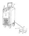
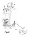
- FIG. 2is a perspective front view of a medical laser user interface system according to an embodiment of the present invention.
- FIG. 3is a plan view of an embodiment of a control panel display for use with the laser unit of FIG. 2 .
- the medical laser system user interface of the present inventionis intended to be used with the Greenlight PVP or HPS, a laser system for the treatment of soft tissues, particularly, a laser system for the photoselective vaporization of prostate tissue in the treatment of BPH (benign prostatic hyperplasia).
- the Greenlight PVP and HPS systemsare manufactured by American Medical Systems, Inc. and are generally described in U.S. Pat. Nos. 6,554,824 and 6,986,764, which are hereby incorporated by reference in their entirety.
- the medical laser user interface system of the present inventionis designed to control a high power medical surgical laser providing simple and intuitive controls and indicators. The interface is well suited for surgical procedures where a laser is used to vaporize and coagulate tissue at different laser power levels.
- FIG. 1is a block diagram depicting an exemplary laser system 100 which may be employed for implementing the present invention.
- Laser system 100includes a solid-state laser 102 , which is used to generate laser light for delivery through optical fiber 106 to target tissue 104 .
- Laser 102is capable of being operated in a continuous wave or pulsed-mode, wherein the laser light is emitted as macro-pulses having relatively long pulse durations.
- Laser 102more specifically comprises a laser element assembly 110 , pump source 112 , and frequency doubling crystal 122 .
- laser element 110outputs 1064 nm light which is focused into frequency doubling crystal 122 to create 532 nm light.
- laser element assembly 110may be neodymium doped YAG (Nd:YAG) crystal, which emits light having a wavelength of 1064 nm (infrared light) when excited by pump source 112 .
- Laser element 110may alternatively be fabricated from any suitable material wherein transition and lanthinide metal ions are disposed within a crystalline host (such as YAG, Lithium Yttrium Fluoride, Sapphire, Alexandrite, Spinel, Yttrium Orthoaluminate, Potassium Gadolinium Tungstate, Yttrium Orthovandate, or Lanthanum Scandium Borate).
- a crystalline hostsuch as YAG, Lithium Yttrium Fluoride, Sapphire, Alexandrite, Spinel, Yttrium Orthoaluminate, Potassium Gadolinium Tungstate, Yttrium Orthovandate, or Lanthanum Scandium Borate.
- Laser element 110is positioned proximal to pump source 112 and may be arranged in parallel relation therewith, although other geometries and configurations may be employed.
- Pump source 112may be any device or apparatus operable to excite laser element assembly 110 .
- Non-limiting examples of devices which may be used as pump source 112include: arc lamps, flashlamps, and laser diodes.
- a Q-switch 114 disposed within laser 102may be operated in a repetitive mode to cause a train of micro-pulses to be generated by laser 102 .
- the micro-pulsesare less than 1 microsecond in duration separated by about 40 microseconds, creating a quasi-continuous wave train.
- Q-switch 114is preferably of the acousto-optic type, but may alternatively comprise a mechanical device such as a rotating prism or aperture, an electro-optical device, or a saturable absorber.
- Control system 116for controlling and operating laser 102 .
- Control system 116will typically include a control processor which receives input from user controls (including but not limited to a beam on/off control, a beam power control, and a pulse duration control, and described in further detail below) and processes the input to accordingly generate output signals for adjusting characteristics of the output beam to match the user inputted values or conditions.
- control system 116applies an output signal to a power supply (not shown) driving pump source 112 which modulates the energy supplied thereto, in turn controlling the pulse duration of the output beam.
- FIG. 1shows an internal frequency doubled laser, it is only by way of example.
- the infrared lightcan be internally or externally frequency doubled using non-linear crystals such as KTP, Lithium Triborate (LBO), or Beta Barium Borate (BBO) to produce second harmonic 532 nm green light, and higher harmonics.
- non-linear crystalssuch as KTP, Lithium Triborate (LBO), or Beta Barium Borate (BBO) to produce second harmonic 532 nm green light, and higher harmonics.
- the frequency doubled, 532 nm wavelength and the shorter wavelength higher harmonic beamsare better absorbed by the tissue, and promote more efficient tissue ablation.
- the resonant cavity control systemis that described in U.S. Pat. No. 5,151,909, which is incorporated by reference as if fully set forth herein.
- Laser 102further includes an output port couplable to optical fiber 106 .
- Output port 118directs the light generated by laser 102 into optical fiber 106 for delivery to tissue 104 .
- Mirrors 124 , 126 , 128 , and 130direct light from the lasing element 110 to the frequency doubling crystal 122 , in addition to forming the resonant cavity of the laser.
- Mirrors 124 , 126 , 128 , and 130are configured for focusing the light to form an image just in front of the frequency doubling crystal 122 on the side closer to mirror 130 , and to compensate for thermal lensing in the lasing element.
- mirrors 124 , 126 , 128 , and 130are illustrated as flat and parallel to the walls of the laser, typically the focusing is achieved by curving and/or angling the mirrors. Alternatively transmissive optical elements could be used to focus the light and compensate for the thermal imaging.
- Mirrors 124 , 128 and 130reflect both the wavelength of light produced by the lasing element (e.g. 1064 nm) and the wavelength of the frequency doubled light (e.g. 532 nm).
- Mirror 126only reflects the light originating from the lasing element 110 (e.g. 1064 nm) but is transparent to the frequency doubled light (e.g. 532 nm), forming an output window.
- Higher harmonic outputsmay also be generated from the 1064 nm line, or other line amplified in the laser, including third and fourth harmonics, for shorter wavelengths.
- Other laser systemsmay be used, including but not limited to Sapphire lasers, diode lasers, and dye lasers, which are adapted to provide the output power and wavelengths described herein, including wavelengths in the ranges from 200 nm to 1000 nm and from 1100 nm to 1800 nm, for example.
- optical fiber 106preferably terminates in a tip 140 having optical elements for shaping and/or orienting the beam emitted by optical fiber 106 so as to optimize the tissue ablation process.
- the tipis preferably a side-firing tip.
- the laser system 100is preferably incorporated into a user console 150 and provides the user with a touch screen interface 152 as well as a foot control system 154 .
- the touch screen interface 152is depicted in detail in FIG. 3 .
- the touch screen interface 152preferably includes a vaporization power indicator 160 with corresponding power adjust buttons, (+) 162 and ( ⁇ ) 164 as well as a coagulation power indicator 166 with corresponding power adjust buttons, (+) 168 and ( ⁇ ) 170 .
- the touch screen interface 152additionally, preferably, includes button controls for READY 172 and STANDBY 174 that also advises the user of which mode is being used by lighting the button controls with indicator lights.
- Another feature of the touch screen user interfaceis the ability to provide the user with the lasing time, indicated in box 176 , and with an energy indicator, indicated in box 178 .
- a reset button 180enables the user to reset the energy and lasing time indicators.
- a set-up button 182enables the user to adjust set-up parameters.
- the foot control system 154preferably includes a READY/STANDBY button 184 that allows the user to toggle between modes with their foot rather than through use of the READY 172 and STANDBY 174 buttons of the touch screen interface.
- the foot control system 154also preferably includes vaporization (VAPOR) pedal 186 and a coagulation (COAG) pedal 188 that enables the user to activate either vaporization or coagulation mode with the touch of their foot rather than through the touch screen 152 .
- VAPOR pedal 186 and the COAG pedal 188are color-coded to the vaporization and coagulation power indicators 160 , 166 on the touch screen 152 .
- the laser system 100i.e., the GreenLight HPS system
- the touch screen 152 and the foot pedal system 154are controlled by the touch screen 152 and the foot pedal system 154 .
- Laser system parametersare selected and the system status is changed by using the touch screen 152 .
- the ready/standby button 184 on top of the foot pedal system 154may be used to go from READY to STANDBY laser status.
- An aiming beam from the laser system 100 that accompanies emission from the optical fiber 106is activated when the laser system 100 is changed from STANDBY to READY and the surgical beam from the optical fiber 106 is activated by pressing the foot pedal, pedal 186 for VAPOR and pedal 188 for COAG.
- Poweris set by touching the power adjust buttons ( 162 , 164 , 168 , 170 ) on the touch screen 152 .
- An audible toneis preferably heard when the maximum or minimum levels are reached. If at any time the laser is unable to deliver the requested power, an alert tone is preferably sounded and the actual power being delivered is displayed in by the vaporization power indicator 160 or the coagulation power indicator 166 , as appropriate to the operational mode.
- the touch screen 152preferably prompts the user to attach the optical fiber 106 .
- the usermay then select the treatment parameters for vaporization and coagulation by touching the power adjust buttons ( 162 , 164 , 168 , 170 ) under the vaporization indicator 160 and the coagulation indicator 166 .
- treatment powermay be changed at any time by touching the power adjust buttons ( 162 , 164 , 168 , 170 ).
- the laser system 100has both an automatic joule counter (energy indicator 178 ) and lasing time indicator 176 , which display the accumulated Joules and the lasing time. To reset both counters, the reset button 180 is preferably pressed.
- the laser system 100is now configured for operation in a treatment procedure, e.g., vaporization of prostate tissue as treatment for BPH.
- the READY button 172is pressed to activate the aiming beam and set up the laser for emission.
- the READY button 172preferably changes color, i.e., to orange, to indicate system readiness.
- Laser energywill now be emitted when one or the other of the footswitches is depressed, pedal 186 for Vaporization and pedal 188 for Coagulation.
- the aiming beamis preferably provided in a blinking mode during coagulation and in a steady mode during vaporization to provide the physician with yet another indicator as to which mode the laser system 100 is operating in.
- An audio toneis preferably heard during emission so that the physician is aware that the laser is emitting, different tones for vaporization and coagulation are preferably used to provide the physician with still another indicator of which mode the laser system 100 is operating in. Additionally, an audio indicator is preferably provided announcing the words corresponding to transitions of the laser system from STANDBY, READY, VAPORIZATION and COAGULATION.
- the laser system 100Upon ending a procedure, the laser system 100 will preferably return to a STANDBY mode after a number of minutes, e.g., two minutes, without any laser emissions.
- the STANDBY button 174 on the touch screen 152can be depressed or the READY/STANDBY footswitch 184 can be pressed. This will disable laser emission and will turn off the aiming beam.
- the laser system 100provides uncomplicated and intuitive controls/indicators in the form of both visual and audible cues, to simplify use of the laser system 100 by the medical professional. These visual and audible cues ensure that the physician has positive indicator for the selected mode even when the laser console is not directly in the visual field of the surgeon.
- the medical laser user interface of the present inventionprovides the user with the ability to rapidly switch between vaporization and coagulation by simply pressing the corresponding foot pedal; a significant improvement over previous laser system that required a single power control to be adjusted when switching between these modes.
- a dedicated laser operatorwould be required to make these adjustments at the laser console incurring the additional expense of the dedicated operator and increasing the opportunity for miscommunication between physician and operator.
- footswitch control of vaporization, coagulation, and ready/standby modesprovides complete control of these functions without the need to access corresponding controls on the laser console itself, which is typically located outside the sterile field.
Landscapes
- Health & Medical Sciences (AREA)
- Surgery (AREA)
- Life Sciences & Earth Sciences (AREA)
- Engineering & Computer Science (AREA)
- Physics & Mathematics (AREA)
- Animal Behavior & Ethology (AREA)
- General Health & Medical Sciences (AREA)
- Biomedical Technology (AREA)
- Heart & Thoracic Surgery (AREA)
- Medical Informatics (AREA)
- Molecular Biology (AREA)
- Nuclear Medicine, Radiotherapy & Molecular Imaging (AREA)
- Public Health (AREA)
- Veterinary Medicine (AREA)
- Optics & Photonics (AREA)
- Electromagnetism (AREA)
- Otolaryngology (AREA)
- Robotics (AREA)
- Human Computer Interaction (AREA)
- Laser Surgery Devices (AREA)
Abstract
Description
Claims (20)
Priority Applications (2)
| Application Number | Priority Date | Filing Date | Title |
|---|---|---|---|
| US12/120,550US9486286B2 (en) | 2007-05-14 | 2008-05-14 | Medical laser user interface |
| US15/291,624US10383690B2 (en) | 2007-05-14 | 2016-10-12 | Medical laser user interface |
Applications Claiming Priority (2)
| Application Number | Priority Date | Filing Date | Title |
|---|---|---|---|
| US91775107P | 2007-05-14 | 2007-05-14 | |
| US12/120,550US9486286B2 (en) | 2007-05-14 | 2008-05-14 | Medical laser user interface |
Related Child Applications (1)
| Application Number | Title | Priority Date | Filing Date |
|---|---|---|---|
| US15/291,624ContinuationUS10383690B2 (en) | 2007-05-14 | 2016-10-12 | Medical laser user interface |
Publications (2)
| Publication Number | Publication Date |
|---|---|
| US20090105698A1 US20090105698A1 (en) | 2009-04-23 |
| US9486286B2true US9486286B2 (en) | 2016-11-08 |
Family
ID=40564210
Family Applications (2)
| Application Number | Title | Priority Date | Filing Date |
|---|---|---|---|
| US12/120,550Active2033-09-03US9486286B2 (en) | 2007-05-14 | 2008-05-14 | Medical laser user interface |
| US15/291,624Active2028-06-08US10383690B2 (en) | 2007-05-14 | 2016-10-12 | Medical laser user interface |
Family Applications After (1)
| Application Number | Title | Priority Date | Filing Date |
|---|---|---|---|
| US15/291,624Active2028-06-08US10383690B2 (en) | 2007-05-14 | 2016-10-12 | Medical laser user interface |
Country Status (1)
| Country | Link |
|---|---|
| US (2) | US9486286B2 (en) |
Cited By (17)
| Publication number | Priority date | Publication date | Assignee | Title |
|---|---|---|---|---|
| US20170027644A1 (en)* | 2007-05-14 | 2017-02-02 | Boston Scientific Scimed, Inc. | Medical laser user interface |
| US11389241B2 (en) | 2019-01-15 | 2022-07-19 | Boston Scientific Scimed, Inc. | Alignment method and tools |
| US11406447B2 (en) | 2019-08-05 | 2022-08-09 | Gyrus Acmi, Inc. | Target identification with optical feedback signal splitter |
| US11622808B2 (en) | 2019-08-05 | 2023-04-11 | Gyrus Acmi, Inc. | Endoscopic laser energy delivery system and methods of use |
| US11666382B2 (en) | 2019-08-05 | 2023-06-06 | Gyrus Acmi, Inc. | Laser control using a spectrometer |
| US11723720B2 (en) | 2019-08-05 | 2023-08-15 | Gyrus Acmi, Inc. | Endoscopic laser system with laser interlock |
| US11819195B2 (en) | 2019-08-05 | 2023-11-21 | Gyrus Acmi, Inc. | Signal coordinated delivery of laser therapy |
| US11882994B2 (en) | 2020-07-24 | 2024-01-30 | Gyrus Acmi, Inc. | Systems and methods for image reconstruction and endoscopic tracking |
| US11957410B2 (en) | 2019-08-05 | 2024-04-16 | Gyrus Acmi, Inc. | Laser fiber-to-target distance control |
| US20240148437A1 (en)* | 2021-02-28 | 2024-05-09 | Coloplast A/S | Electronic device for the operation of an endourological laser surgery system and associated method |
| US12023097B2 (en) | 2019-08-05 | 2024-07-02 | Gyrus Acmi, Inc. | Selective laser firing for tissue safety |
| US12053149B2 (en) | 2020-08-05 | 2024-08-06 | Gyrus Acmi, Inc. | Depth and contour detection for targets |
| US12137878B2 (en) | 2019-08-05 | 2024-11-12 | Gyrus Acmi, Inc. | Multi-fiber medical optical system |
| US12150623B2 (en) | 2020-08-05 | 2024-11-26 | Gyrus Acmi, Inc. | Techniques for composition identification of an anatomical target |
| US12279812B2 (en) | 2019-08-05 | 2025-04-22 | Gyrus Acmi, Inc. | Laser fiber varying lateral position and intensity |
| US12357382B2 (en) | 2020-07-21 | 2025-07-15 | Gyrus Acmi, Inc. | Laser treatment using acoustic feedback |
| US12440087B2 (en) | 2023-11-21 | 2025-10-14 | Gyrus Acmi, Inc. | Systems and methods for endoscopic image reconstruction |
Families Citing this family (18)
| Publication number | Priority date | Publication date | Assignee | Title |
|---|---|---|---|---|
| WO2010111604A1 (en)* | 2009-03-27 | 2010-09-30 | Ams Research Corporation | Laser modulation for coagulation |
| EP2512322A4 (en) | 2009-12-17 | 2013-09-18 | Alcon Res Ltd | Photonic lattice leds for ophthalmic illumination |
| WO2011078958A1 (en)* | 2009-12-23 | 2011-06-30 | Alcon Research, Ltd. | Enhanced led illuminator |
| US9314374B2 (en) | 2010-03-19 | 2016-04-19 | Alcon Research, Ltd. | Stroboscopic ophthalmic illuminator |
| US8573801B2 (en) | 2010-08-30 | 2013-11-05 | Alcon Research, Ltd. | LED illuminator |
| US8672929B2 (en) | 2010-12-15 | 2014-03-18 | Ams Research Corporation | Laser probe tip |
| US8685011B2 (en) | 2010-12-15 | 2014-04-01 | Ams Research Corporation | Tunica ablation |
| US20140018782A1 (en)* | 2011-03-29 | 2014-01-16 | Gregory Flynn | System, Method, and Apparatus for Performing Surgery using High Power Light Energy |
| US9968403B2 (en)* | 2012-10-16 | 2018-05-15 | Boston Scientific Scimed, Inc. | Surgical laser system and laser fiber |
| WO2014072806A1 (en)* | 2012-11-09 | 2014-05-15 | Biolitec Pharma Marketing Ltd. | Device and method for laser treatments |
| US9808639B2 (en)* | 2012-12-26 | 2017-11-07 | Koninklijke Philips N.V. | Intuitive overlaid readiness indicator for defibrillators |
| US11583462B2 (en)* | 2013-03-12 | 2023-02-21 | Biolase, Inc. | Dental laser unit with communication link to assistance center |
| CN105266892A (en)* | 2015-10-16 | 2016-01-27 | 中国人民解放军第四军医大学 | Bipolar electric condenser adjustment and control device |
| US11172560B2 (en) | 2016-08-25 | 2021-11-09 | Alcon Inc. | Ophthalmic illumination system with controlled chromaticity |
| WO2018053241A1 (en)* | 2016-09-16 | 2018-03-22 | Boston Scientific Scimed, Inc. | Dual-wavelength laser treatment |
| AU2018347507B2 (en)* | 2017-10-13 | 2024-01-25 | Boston Scientific Scimed, Inc. | Medical systems, devices, and related methods |
| JP2024511183A (en)* | 2021-03-26 | 2024-03-12 | シー・アール・バード・インコーポレーテッド | Medical device projection system |
| WO2023107364A1 (en)* | 2021-12-06 | 2023-06-15 | Covidien Lp | Graphic user interface foot pedals for a surgical robotic system |
Citations (27)
| Publication number | Priority date | Publication date | Assignee | Title |
|---|---|---|---|---|
| US3769963A (en)* | 1972-03-31 | 1973-11-06 | L Goldman | Instrument for performing laser micro-surgery and diagnostic transillumination of living human tissue |
| US4388924A (en)* | 1981-05-21 | 1983-06-21 | Weissman Howard R | Method for laser depilation |
| US5139494A (en)* | 1988-11-10 | 1992-08-18 | Premier Laser Systems, Inc. | Multiwavelength medical laser method |
| US6254601B1 (en) | 1998-12-08 | 2001-07-03 | Hysterx, Inc. | Methods for occlusion of the uterine arteries |
| US6267779B1 (en)* | 1999-03-29 | 2001-07-31 | Medelaser, Llc | Method and apparatus for therapeutic laser treatment |
| US20020026225A1 (en)* | 1992-04-24 | 2002-02-28 | Segal Kim Robin | Diode laser irradiation and electrotherapy system for biological tissue stimulation |
| US20020165579A1 (en) | 2001-03-28 | 2002-11-07 | Burbank Fred H. | Multi-axial uterine artery identification, characterization, and occlusion devices and methods |
| US6506156B1 (en) | 2000-01-19 | 2003-01-14 | Vascular Control Systems, Inc | Echogenic coating |
| US6546933B1 (en) | 2000-06-29 | 2003-04-15 | Inbae Yoon | Occlusion apparatus and method for necrotizing anatomical tissue structures |
| US6550482B1 (en) | 2000-04-21 | 2003-04-22 | Vascular Control Systems, Inc. | Methods for non-permanent occlusion of a uterine artery |
| US20030120306A1 (en) | 2000-04-21 | 2003-06-26 | Vascular Control System | Method and apparatus for the detection and occlusion of blood vessels |
| US20030120286A1 (en) | 2001-03-28 | 2003-06-26 | Vascular Control System | Luminal clip applicator with sensor |
| US6635065B2 (en) | 2000-11-16 | 2003-10-21 | Vascular Control Systems, Inc. | Doppler directed suture ligation device and method |
| US6638286B1 (en) | 2000-11-16 | 2003-10-28 | Vascular Control Systems, Inc. | Doppler directed suture ligation device and method |
| US20040049180A1 (en)* | 1996-07-16 | 2004-03-11 | Arthrocare Corporation | Systems and methods for electrosurgical prevention of disc herniations |
| US20040092979A1 (en) | 2001-03-28 | 2004-05-13 | Vascular Control System | Occlusion device with deployable paddles for detection and occlusion of blood vessels |
| US20040097961A1 (en) | 2002-11-19 | 2004-05-20 | Vascular Control System | Tenaculum for use with occlusion devices |
| US20040202694A1 (en) | 2003-04-11 | 2004-10-14 | Vascular Control Systems, Inc. | Embolic occlusion of uterine arteries |
| US20050043828A1 (en)* | 2003-08-19 | 2005-02-24 | Olympus Corporation | Control device for a medical system and control method for medical system |
| US7172603B2 (en) | 2002-11-19 | 2007-02-06 | Vascular Control Systems, Inc. | Deployable constrictor for uterine artery occlusion |
| US7180922B2 (en)* | 2003-11-12 | 2007-02-20 | Ceramoptec Industries, Inc. | Safety system for focused energy applications |
| US7207996B2 (en) | 2002-04-04 | 2007-04-24 | Vascular Control Systems, Inc. | Doppler directed suturing and compression device and method |
| US7223279B2 (en) | 2000-04-21 | 2007-05-29 | Vascular Control Systems, Inc. | Methods for minimally-invasive, non-permanent occlusion of a uterine artery |
| US7325546B2 (en) | 2003-11-20 | 2008-02-05 | Vascular Control Systems, Inc. | Uterine artery occlusion device with cervical receptacle |
| US7329265B2 (en) | 2003-01-30 | 2008-02-12 | Vascular Control Systems, Inc. | Uterine artery occlusion clamp |
| US20080086117A1 (en)* | 2004-09-22 | 2008-04-10 | Cao Group, Inc. | Modular Surgical Laser Systems |
| US8465473B2 (en)* | 2007-03-28 | 2013-06-18 | Novartis Ag | Surgical footswitch with movable shroud |
Family Cites Families (3)
| Publication number | Priority date | Publication date | Assignee | Title |
|---|---|---|---|---|
| US5151909A (en)* | 1990-10-16 | 1992-09-29 | Laserscope | Frequency doubled solid state laser having programmable pump power modes and method for controllable lasers |
| DE102005013466B3 (en)* | 2005-03-21 | 2006-10-05 | Netzsch-Mohnopumpen Gmbh | jig |
| US9486286B2 (en)* | 2007-05-14 | 2016-11-08 | Boston Scientific Scimed, Inc. | Medical laser user interface |
- 2008
- 2008-05-14USUS12/120,550patent/US9486286B2/enactiveActive
- 2016
- 2016-10-12USUS15/291,624patent/US10383690B2/enactiveActive
Patent Citations (30)
| Publication number | Priority date | Publication date | Assignee | Title |
|---|---|---|---|---|
| US3769963A (en)* | 1972-03-31 | 1973-11-06 | L Goldman | Instrument for performing laser micro-surgery and diagnostic transillumination of living human tissue |
| US4388924A (en)* | 1981-05-21 | 1983-06-21 | Weissman Howard R | Method for laser depilation |
| US5139494A (en)* | 1988-11-10 | 1992-08-18 | Premier Laser Systems, Inc. | Multiwavelength medical laser method |
| US20020026225A1 (en)* | 1992-04-24 | 2002-02-28 | Segal Kim Robin | Diode laser irradiation and electrotherapy system for biological tissue stimulation |
| US20040049180A1 (en)* | 1996-07-16 | 2004-03-11 | Arthrocare Corporation | Systems and methods for electrosurgical prevention of disc herniations |
| US6254601B1 (en) | 1998-12-08 | 2001-07-03 | Hysterx, Inc. | Methods for occlusion of the uterine arteries |
| US6602251B2 (en) | 1998-12-08 | 2003-08-05 | Vascular Control Systems, Inc. | Device and methods for occlusion of the uterine artieries |
| US6267779B1 (en)* | 1999-03-29 | 2001-07-31 | Medelaser, Llc | Method and apparatus for therapeutic laser treatment |
| US6506156B1 (en) | 2000-01-19 | 2003-01-14 | Vascular Control Systems, Inc | Echogenic coating |
| US7223279B2 (en) | 2000-04-21 | 2007-05-29 | Vascular Control Systems, Inc. | Methods for minimally-invasive, non-permanent occlusion of a uterine artery |
| US20030120306A1 (en) | 2000-04-21 | 2003-06-26 | Vascular Control System | Method and apparatus for the detection and occlusion of blood vessels |
| US6550482B1 (en) | 2000-04-21 | 2003-04-22 | Vascular Control Systems, Inc. | Methods for non-permanent occlusion of a uterine artery |
| US6546933B1 (en) | 2000-06-29 | 2003-04-15 | Inbae Yoon | Occlusion apparatus and method for necrotizing anatomical tissue structures |
| US6638286B1 (en) | 2000-11-16 | 2003-10-28 | Vascular Control Systems, Inc. | Doppler directed suture ligation device and method |
| US6635065B2 (en) | 2000-11-16 | 2003-10-21 | Vascular Control Systems, Inc. | Doppler directed suture ligation device and method |
| US20030120286A1 (en) | 2001-03-28 | 2003-06-26 | Vascular Control System | Luminal clip applicator with sensor |
| US20040092979A1 (en) | 2001-03-28 | 2004-05-13 | Vascular Control System | Occlusion device with deployable paddles for detection and occlusion of blood vessels |
| US20020165579A1 (en) | 2001-03-28 | 2002-11-07 | Burbank Fred H. | Multi-axial uterine artery identification, characterization, and occlusion devices and methods |
| US7229465B2 (en) | 2001-03-28 | 2007-06-12 | Vascular Control Systems, Inc. | Method and apparatus for the detection and ligation of uterine arteries |
| US7207996B2 (en) | 2002-04-04 | 2007-04-24 | Vascular Control Systems, Inc. | Doppler directed suturing and compression device and method |
| US20040097961A1 (en) | 2002-11-19 | 2004-05-20 | Vascular Control System | Tenaculum for use with occlusion devices |
| US20040158262A1 (en) | 2002-11-19 | 2004-08-12 | Vascular Control Systems, Inc. | Tenaculum-like device for intravaginal instrument delivery |
| US7172603B2 (en) | 2002-11-19 | 2007-02-06 | Vascular Control Systems, Inc. | Deployable constrictor for uterine artery occlusion |
| US7329265B2 (en) | 2003-01-30 | 2008-02-12 | Vascular Control Systems, Inc. | Uterine artery occlusion clamp |
| US20040202694A1 (en) | 2003-04-11 | 2004-10-14 | Vascular Control Systems, Inc. | Embolic occlusion of uterine arteries |
| US20050043828A1 (en)* | 2003-08-19 | 2005-02-24 | Olympus Corporation | Control device for a medical system and control method for medical system |
| US7180922B2 (en)* | 2003-11-12 | 2007-02-20 | Ceramoptec Industries, Inc. | Safety system for focused energy applications |
| US7325546B2 (en) | 2003-11-20 | 2008-02-05 | Vascular Control Systems, Inc. | Uterine artery occlusion device with cervical receptacle |
| US20080086117A1 (en)* | 2004-09-22 | 2008-04-10 | Cao Group, Inc. | Modular Surgical Laser Systems |
| US8465473B2 (en)* | 2007-03-28 | 2013-06-18 | Novartis Ag | Surgical footswitch with movable shroud |
Non-Patent Citations (3)
| Title |
|---|
| Burbank, et al, "Uterine Artery Occlusion by Embolization or Surgery for the Treatment of Fibroids: A Unifying Hypothesis-Transient Uterine Ischemia," The Journal of the American Association of Gynecologic Laparoscopists, Nov. 2000, vol. 7, No. 4 Supplement, pp. S3-S49. |
| Harmanli, MD et al, "Trans-vaginal Uterine Artery Ligation in a Woman with Uterine Leiomyomas", Journal of Reproductive Medicine, May 2003, vol. 48; pp. 384-386. |
| Ravina et al, "Arterial Embolization to Treat Uterine Myomata", Lancet, 1995; vol. 344: pp. 671-692. |
Cited By (26)
| Publication number | Priority date | Publication date | Assignee | Title |
|---|---|---|---|---|
| US10383690B2 (en)* | 2007-05-14 | 2019-08-20 | Boston Scientific Scimed, Inc. | Medical laser user interface |
| US20170027644A1 (en)* | 2007-05-14 | 2017-02-02 | Boston Scientific Scimed, Inc. | Medical laser user interface |
| US11844494B2 (en) | 2019-01-15 | 2023-12-19 | Boston Scientific Scimed, Inc. | Alignment method and tools |
| US11389241B2 (en) | 2019-01-15 | 2022-07-19 | Boston Scientific Scimed, Inc. | Alignment method and tools |
| US12171491B2 (en) | 2019-08-05 | 2024-12-24 | Gyrus Acmi, Inc. | Endoscopic laser energy delivery system and methods of use |
| US11957410B2 (en) | 2019-08-05 | 2024-04-16 | Gyrus Acmi, Inc. | Laser fiber-to-target distance control |
| US11666382B2 (en) | 2019-08-05 | 2023-06-06 | Gyrus Acmi, Inc. | Laser control using a spectrometer |
| US11723720B2 (en) | 2019-08-05 | 2023-08-15 | Gyrus Acmi, Inc. | Endoscopic laser system with laser interlock |
| US11819195B2 (en) | 2019-08-05 | 2023-11-21 | Gyrus Acmi, Inc. | Signal coordinated delivery of laser therapy |
| US11523865B2 (en) | 2019-08-05 | 2022-12-13 | Gyrus Acmi, Inc. | Target identification with optical feedback signal splitter |
| US11622808B2 (en) | 2019-08-05 | 2023-04-11 | Gyrus Acmi, Inc. | Endoscopic laser energy delivery system and methods of use |
| US12207869B2 (en) | 2019-08-05 | 2025-01-28 | Gyrus Acmi, Inc. | Target identification with optical feedback signal splitter |
| US11406447B2 (en) | 2019-08-05 | 2022-08-09 | Gyrus Acmi, Inc. | Target identification with optical feedback signal splitter |
| US11980350B2 (en) | 2019-08-05 | 2024-05-14 | Gyrus Acmi, Inc. | Laser system with illumination control |
| US12023097B2 (en) | 2019-08-05 | 2024-07-02 | Gyrus Acmi, Inc. | Selective laser firing for tissue safety |
| US12279812B2 (en) | 2019-08-05 | 2025-04-22 | Gyrus Acmi, Inc. | Laser fiber varying lateral position and intensity |
| US12137878B2 (en) | 2019-08-05 | 2024-11-12 | Gyrus Acmi, Inc. | Multi-fiber medical optical system |
| US12220166B2 (en) | 2019-08-05 | 2025-02-11 | Gyrus Acmi, Inc. | Target identification with optical feedback signal splitter |
| US12357382B2 (en) | 2020-07-21 | 2025-07-15 | Gyrus Acmi, Inc. | Laser treatment using acoustic feedback |
| US11882994B2 (en) | 2020-07-24 | 2024-01-30 | Gyrus Acmi, Inc. | Systems and methods for image reconstruction and endoscopic tracking |
| US12150623B2 (en) | 2020-08-05 | 2024-11-26 | Gyrus Acmi, Inc. | Techniques for composition identification of an anatomical target |
| US12053149B2 (en) | 2020-08-05 | 2024-08-06 | Gyrus Acmi, Inc. | Depth and contour detection for targets |
| US12402775B2 (en) | 2020-08-05 | 2025-09-02 | Gyrus Acmi, Inc. | Depth and contour detection for anatomical targets |
| US20240148437A1 (en)* | 2021-02-28 | 2024-05-09 | Coloplast A/S | Electronic device for the operation of an endourological laser surgery system and associated method |
| US12440087B2 (en) | 2023-11-21 | 2025-10-14 | Gyrus Acmi, Inc. | Systems and methods for endoscopic image reconstruction |
| US12440269B2 (en) | 2024-01-26 | 2025-10-14 | Gyrus Acmi, Inc. | Laser fiber-to-target distance control |
Also Published As
| Publication number | Publication date |
|---|---|
| US20170027644A1 (en) | 2017-02-02 |
| US20090105698A1 (en) | 2009-04-23 |
| US10383690B2 (en) | 2019-08-20 |
Similar Documents
| Publication | Publication Date | Title |
|---|---|---|
| US10383690B2 (en) | Medical laser user interface | |
| EP3694437B1 (en) | Medical systems, devices, and related methods | |
| US10653482B2 (en) | System for vaporization of tissue | |
| US10426547B2 (en) | Surgical laser system and laser fiber | |
| US7063694B2 (en) | Method and system for photoselective vaporization for gynecological treatments | |
| CA2248180C (en) | Laser surgical device and method of its use | |
| US6554824B2 (en) | Methods for laser treatment of soft tissue | |
| WO1996028212A1 (en) | Laser surgical device and method of its use | |
| JP2002011106A (en) | Laser therapeutic apparatus | |
| WO2016184215A1 (en) | Imaging dot matrix laser treatment instrument | |
| US20030130649A1 (en) | Method and system for treatment of benign prostatic hypertrophy (BPH) | |
| KR100876975B1 (en) | operation unit using laser | |
| JP2001008946A (en) | Laser surgery equipment | |
| Fortune et al. | Effect of laser-pulse structure and wavelength on wound healing | |
| JP2005111163A (en) | Laser therapy equipment |
Legal Events
| Date | Code | Title | Description |
|---|---|---|---|
| AS | Assignment | Owner name:AMS RESEARCH CORPORATION, MINNESOTA Free format text:ASSIGNMENT OF ASSIGNORS INTEREST;ASSIGNORS:HODEL, MICHAEL R.;SMITH, TERRY J.;REEL/FRAME:021602/0122 Effective date:20080618 | |
| AS | Assignment | Owner name:MORGAN STANLEY SENIOR FUNDING, INC., AS ADMINISTRA Free format text:SECURITY AGREEMENT;ASSIGNOR:AMS RESEARCH CORPORATION;REEL/FRAME:026632/0535 Effective date:20110617 | |
| AS | Assignment | Owner name:AMS RESEARCH CORPORATION, MINNESOTA Free format text:RELEASE OF PATENT SECURITY INTEREST;ASSIGNOR:MORGAN STANLEY SENIOR FUNDING, INC., AS ADMINISTRATIVE AGENT;REEL/FRAME:032380/0053 Effective date:20140228 | |
| AS | Assignment | Owner name:DEUTSCHE BANK AG NEW YORK BRANCH, AS COLLATERAL AGENT, NEW YORK Free format text:GRANT OF SECURITY INTEREST IN PATENTS;ASSIGNORS:ENDO PHARMACEUTICALS SOLUTIONS, INC.;ENDO PHARMACEUTICALS, INC.;AMS RESEARCH CORPORATION;AND OTHERS;REEL/FRAME:032491/0440 Effective date:20140228 Owner name:DEUTSCHE BANK AG NEW YORK BRANCH, AS COLLATERAL AG Free format text:GRANT OF SECURITY INTEREST IN PATENTS;ASSIGNORS:ENDO PHARMACEUTICALS SOLUTIONS, INC.;ENDO PHARMACEUTICALS, INC.;AMS RESEARCH CORPORATION;AND OTHERS;REEL/FRAME:032491/0440 Effective date:20140228 | |
| AS | Assignment | Owner name:AMERICAN MEDICAL SYSTEMS, LLC, MINNESOTA Free format text:RELEASE BY SECURED PARTY;ASSIGNOR:DEUTSCHE BANK AG NEW YORK BRANCH;REEL/FRAME:036285/0146 Effective date:20150803 Owner name:LASERSCOPE, CALIFORNIA Free format text:RELEASE BY SECURED PARTY;ASSIGNOR:DEUTSCHE BANK AG NEW YORK BRANCH;REEL/FRAME:036285/0146 Effective date:20150803 Owner name:AMS RESEARCH, LLC, MINNESOTA Free format text:RELEASE BY SECURED PARTY;ASSIGNOR:DEUTSCHE BANK AG NEW YORK BRANCH;REEL/FRAME:036285/0146 Effective date:20150803 | |
| FEPP | Fee payment procedure | Free format text:PAYOR NUMBER ASSIGNED (ORIGINAL EVENT CODE: ASPN); ENTITY STATUS OF PATENT OWNER: LARGE ENTITY | |
| AS | Assignment | Owner name:BOSTON SCIENTIFIC SCIMED, INC., MINNESOTA Free format text:ASSIGNMENT OF ASSIGNORS INTEREST;ASSIGNOR:AMERICAN MEDICAL SYSTEMS, LLC;REEL/FRAME:037902/0200 Effective date:20151210 Owner name:BOSTON SCIENTIFIC SCIMED, INC., MINNESOTA Free format text:ASSIGNMENT OF ASSIGNORS INTEREST;ASSIGNOR:AMS RESEARCH, LLC;REEL/FRAME:037902/0162 Effective date:20151210 | |
| AS | Assignment | Owner name:AMS RESEARCH, LLC, MINNESOTA Free format text:CHANGE OF NAME;ASSIGNOR:AMS RESEARCH COPORATION;REEL/FRAME:039050/0608 Effective date:20141217 | |
| STCF | Information on status: patent grant | Free format text:PATENTED CASE | |
| MAFP | Maintenance fee payment | Free format text:PAYMENT OF MAINTENANCE FEE, 4TH YEAR, LARGE ENTITY (ORIGINAL EVENT CODE: M1551); ENTITY STATUS OF PATENT OWNER: LARGE ENTITY Year of fee payment:4 | |
| MAFP | Maintenance fee payment | Free format text:PAYMENT OF MAINTENANCE FEE, 8TH YEAR, LARGE ENTITY (ORIGINAL EVENT CODE: M1552); ENTITY STATUS OF PATENT OWNER: LARGE ENTITY Year of fee payment:8 |