US9486264B2 - Systems and methods for the fixation or fusion of bone using compressive implants - Google Patents
Systems and methods for the fixation or fusion of bone using compressive implantsDownload PDFInfo
- Publication number
- US9486264B2 US9486264B2US14/274,486US201414274486AUS9486264B2US 9486264 B2US9486264 B2US 9486264B2US 201414274486 AUS201414274486 AUS 201414274486AUS 9486264 B2US9486264 B2US 9486264B2
- Authority
- US
- United States
- Prior art keywords
- bone
- implant
- joint
- anchor body
- anchor
- Prior art date
- Legal status (The legal status is an assumption and is not a legal conclusion. Google has not performed a legal analysis and makes no representation as to the accuracy of the status listed.)
- Expired - Lifetime
Links
- 239000007943implantSubstances0.000titleclaimsabstractdescription189
- 230000004927fusionEffects0.000titleclaimsdescription39
- 238000000034methodMethods0.000titleclaimsdescription36
- 210000000988bone and boneAnatomy0.000titleabstractdescription167
- 238000003780insertionMethods0.000claimsabstractdescription18
- 230000037431insertionEffects0.000claimsabstractdescription18
- 210000003131sacroiliac jointAnatomy0.000claimsdescription77
- 238000004873anchoringMethods0.000claimsdescription4
- 210000003405ileumAnatomy0.000claims7
- 238000007493shaping processMethods0.000claims3
- 238000005553drillingMethods0.000claims1
- 230000006835compressionEffects0.000abstractdescription83
- 238000007906compressionMethods0.000abstractdescription83
- 210000003692iliumAnatomy0.000description46
- 238000013459approachMethods0.000description43
- 208000010392Bone FracturesDiseases0.000description17
- 230000000712assemblyEffects0.000description17
- 238000000429assemblyMethods0.000description17
- 239000000463materialSubstances0.000description15
- 206010017076FractureDiseases0.000description14
- 238000002513implantationMethods0.000description13
- 210000004872soft tissueAnatomy0.000description11
- 210000003484anatomyAnatomy0.000description8
- 230000001012protectorEffects0.000description7
- 210000001519tissueAnatomy0.000description7
- 238000010521absorption reactionMethods0.000description6
- 239000000853adhesiveSubstances0.000description6
- 230000001070adhesive effectEffects0.000description6
- 238000003754machiningMethods0.000description6
- 229910052751metalInorganic materials0.000description6
- RTAQQCXQSZGOHL-UHFFFAOYSA-NTitaniumChemical compound[Ti]RTAQQCXQSZGOHL-UHFFFAOYSA-N0.000description5
- 239000000919ceramicSubstances0.000description5
- 230000000295complement effectEffects0.000description5
- 238000002595magnetic resonance imagingMethods0.000description5
- 239000002184metalSubstances0.000description5
- 239000010936titaniumSubstances0.000description5
- 229910052719titaniumInorganic materials0.000description5
- 230000015572biosynthetic processEffects0.000description4
- 210000001981hip boneAnatomy0.000description4
- 238000013508migrationMethods0.000description4
- 230000005012migrationEffects0.000description4
- 238000000465mouldingMethods0.000description4
- 238000001356surgical procedureMethods0.000description4
- 229910000684Cobalt-chromeInorganic materials0.000description3
- 208000002193PainDiseases0.000description3
- 229910001069Ti alloyInorganic materials0.000description3
- 208000027418Wounds and injuryDiseases0.000description3
- 238000004458analytical methodMethods0.000description3
- 239000012620biological materialSubstances0.000description3
- 238000002591computed tomographyMethods0.000description3
- 230000006378damageEffects0.000description3
- 201000010099diseaseDiseases0.000description3
- 208000037265diseases, disorders, signs and symptomsDiseases0.000description3
- 208000014674injuryDiseases0.000description3
- 238000010079rubber tappingMethods0.000description3
- 238000000926separation methodMethods0.000description3
- 210000002784stomachAnatomy0.000description3
- 229910000811surgical stainless steelInorganic materials0.000description3
- 229910052715tantalumInorganic materials0.000description3
- GUVRBAGPIYLISA-UHFFFAOYSA-Ntantalum atomChemical compound[Ta]GUVRBAGPIYLISA-UHFFFAOYSA-N0.000description3
- 238000007794visualization techniqueMethods0.000description3
- 101000911772Homo sapiens Hsc70-interacting proteinProteins0.000description2
- 206010039361SacroiliitisDiseases0.000description2
- 208000037873arthrodesisDiseases0.000description2
- 230000004323axial lengthEffects0.000description2
- 210000000845cartilageAnatomy0.000description2
- 239000003795chemical substances by applicationSubstances0.000description2
- CRQQGFGUEAVUIL-UHFFFAOYSA-NchlorothalonilChemical compoundClC1=C(Cl)C(C#N)=C(Cl)C(C#N)=C1ClCRQQGFGUEAVUIL-UHFFFAOYSA-N0.000description2
- 230000003412degenerative effectEffects0.000description2
- 230000009969flowable effectEffects0.000description2
- 238000007499fusion processingMethods0.000description2
- 239000011521glassSubstances0.000description2
- 230000035876healingEffects0.000description2
- 238000002347injectionMethods0.000description2
- 239000007924injectionSubstances0.000description2
- 238000012423maintenanceMethods0.000description2
- 210000005036nerveAnatomy0.000description2
- 238000005507sprayingMethods0.000description2
- 230000000087stabilizing effectEffects0.000description2
- 238000012360testing methodMethods0.000description2
- 241001631457CannulaSpecies0.000description1
- 208000008930Low Back PainDiseases0.000description1
- 206010031150Osteitis condensansDiseases0.000description1
- 206010049514Traumatic fractureDiseases0.000description1
- 239000003522acrylic cementSubstances0.000description1
- 230000001154acute effectEffects0.000description1
- 229910052782aluminiumInorganic materials0.000description1
- XAGFODPZIPBFFR-UHFFFAOYSA-NaluminiumChemical compound[Al]XAGFODPZIPBFFR-UHFFFAOYSA-N0.000description1
- 230000000845anti-microbial effectEffects0.000description1
- 230000002785anti-thrombosisEffects0.000description1
- 239000003146anticoagulant agentSubstances0.000description1
- 230000005540biological transmissionEffects0.000description1
- 239000008280bloodSubstances0.000description1
- 210000004369bloodAnatomy0.000description1
- 238000000576coating methodMethods0.000description1
- 238000010276constructionMethods0.000description1
- 238000013461designMethods0.000description1
- -1e.g.Substances0.000description1
- 239000012634fragmentSubstances0.000description1
- 230000036541healthEffects0.000description1
- 230000000642iatrogenic effectEffects0.000description1
- 210000001621ilium boneAnatomy0.000description1
- 238000010348incorporationMethods0.000description1
- 208000015181infectious diseaseDiseases0.000description1
- 230000002757inflammatory effectEffects0.000description1
- 238000009434installationMethods0.000description1
- 230000001788irregularEffects0.000description1
- 230000007794irritationEffects0.000description1
- 210000003141lower extremityAnatomy0.000description1
- 210000004705lumbosacral regionAnatomy0.000description1
- 230000013011matingEffects0.000description1
- 239000007769metal materialSubstances0.000description1
- 238000012986modificationMethods0.000description1
- 230000004048modificationEffects0.000description1
- 230000002138osteoinductive effectEffects0.000description1
- 210000004197pelvisAnatomy0.000description1
- 239000011148porous materialSubstances0.000description1
- 238000002360preparation methodMethods0.000description1
- 230000000284resting effectEffects0.000description1
- 238000007790scrapingMethods0.000description1
- 239000011343solid materialSubstances0.000description1
- 210000002435tendonAnatomy0.000description1
- 229910052720vanadiumInorganic materials0.000description1
- LEONUFNNVUYDNQ-UHFFFAOYSA-Nvanadium atomChemical compound[V]LEONUFNNVUYDNQ-UHFFFAOYSA-N0.000description1
- 238000012800visualizationMethods0.000description1
Images


Classifications
- A—HUMAN NECESSITIES
- A61—MEDICAL OR VETERINARY SCIENCE; HYGIENE
- A61B—DIAGNOSIS; SURGERY; IDENTIFICATION
- A61B17/00—Surgical instruments, devices or methods
- A61B17/16—Instruments for performing osteoclasis; Drills or chisels for bones; Trepans
- A61B17/1659—Surgical rasps, files, planes, or scrapers
- A—HUMAN NECESSITIES
- A61—MEDICAL OR VETERINARY SCIENCE; HYGIENE
- A61B—DIAGNOSIS; SURGERY; IDENTIFICATION
- A61B17/00—Surgical instruments, devices or methods
- A61B17/56—Surgical instruments or methods for treatment of bones or joints; Devices specially adapted therefor
- A61B17/58—Surgical instruments or methods for treatment of bones or joints; Devices specially adapted therefor for osteosynthesis, e.g. bone plates, screws or setting implements
- A61B17/68—Internal fixation devices, including fasteners and spinal fixators, even if a part thereof projects from the skin
- A61B17/84—Fasteners therefor or fasteners being internal fixation devices
- A61B17/86—Pins or screws or threaded wires; nuts therefor
- A61B17/8625—Shanks, i.e. parts contacting bone tissue
- A61B17/863—Shanks, i.e. parts contacting bone tissue with thread interrupted or changing its form along shank, other than constant taper
- A—HUMAN NECESSITIES
- A61—MEDICAL OR VETERINARY SCIENCE; HYGIENE
- A61B—DIAGNOSIS; SURGERY; IDENTIFICATION
- A61B17/00—Surgical instruments, devices or methods
- A61B17/16—Instruments for performing osteoclasis; Drills or chisels for bones; Trepans
- A61B17/17—Guides or aligning means for drills, mills, pins or wires
- A61B17/1739—Guides or aligning means for drills, mills, pins or wires specially adapted for particular parts of the body
- A61B17/1757—Guides or aligning means for drills, mills, pins or wires specially adapted for particular parts of the body for the spine
- A—HUMAN NECESSITIES
- A61—MEDICAL OR VETERINARY SCIENCE; HYGIENE
- A61B—DIAGNOSIS; SURGERY; IDENTIFICATION
- A61B17/00—Surgical instruments, devices or methods
- A61B17/16—Instruments for performing osteoclasis; Drills or chisels for bones; Trepans
- A61B17/1662—Instruments for performing osteoclasis; Drills or chisels for bones; Trepans for particular parts of the body
- A61B17/1671—Instruments for performing osteoclasis; Drills or chisels for bones; Trepans for particular parts of the body for the spine
- A—HUMAN NECESSITIES
- A61—MEDICAL OR VETERINARY SCIENCE; HYGIENE
- A61B—DIAGNOSIS; SURGERY; IDENTIFICATION
- A61B17/00—Surgical instruments, devices or methods
- A61B17/56—Surgical instruments or methods for treatment of bones or joints; Devices specially adapted therefor
- A61B17/58—Surgical instruments or methods for treatment of bones or joints; Devices specially adapted therefor for osteosynthesis, e.g. bone plates, screws or setting implements
- A61B17/68—Internal fixation devices, including fasteners and spinal fixators, even if a part thereof projects from the skin
- A61B17/686—Plugs, i.e. elements forming interface between bone hole and implant or fastener, e.g. screw
- A—HUMAN NECESSITIES
- A61—MEDICAL OR VETERINARY SCIENCE; HYGIENE
- A61B—DIAGNOSIS; SURGERY; IDENTIFICATION
- A61B17/00—Surgical instruments, devices or methods
- A61B17/56—Surgical instruments or methods for treatment of bones or joints; Devices specially adapted therefor
- A61B17/58—Surgical instruments or methods for treatment of bones or joints; Devices specially adapted therefor for osteosynthesis, e.g. bone plates, screws or setting implements
- A61B17/68—Internal fixation devices, including fasteners and spinal fixators, even if a part thereof projects from the skin
- A61B17/70—Spinal positioners or stabilisers, e.g. stabilisers comprising fluid filler in an implant
- A61B17/7055—Spinal positioners or stabilisers, e.g. stabilisers comprising fluid filler in an implant connected to sacrum, pelvis or skull
- A—HUMAN NECESSITIES
- A61—MEDICAL OR VETERINARY SCIENCE; HYGIENE
- A61B—DIAGNOSIS; SURGERY; IDENTIFICATION
- A61B17/00—Surgical instruments, devices or methods
- A61B17/56—Surgical instruments or methods for treatment of bones or joints; Devices specially adapted therefor
- A61B17/58—Surgical instruments or methods for treatment of bones or joints; Devices specially adapted therefor for osteosynthesis, e.g. bone plates, screws or setting implements
- A61B17/68—Internal fixation devices, including fasteners and spinal fixators, even if a part thereof projects from the skin
- A61B17/84—Fasteners therefor or fasteners being internal fixation devices
- A61B17/86—Pins or screws or threaded wires; nuts therefor
- A61B17/864—Pins or screws or threaded wires; nuts therefor hollow, e.g. with socket or cannulated
- A—HUMAN NECESSITIES
- A61—MEDICAL OR VETERINARY SCIENCE; HYGIENE
- A61B—DIAGNOSIS; SURGERY; IDENTIFICATION
- A61B17/00—Surgical instruments, devices or methods
- A61B17/56—Surgical instruments or methods for treatment of bones or joints; Devices specially adapted therefor
- A61B17/58—Surgical instruments or methods for treatment of bones or joints; Devices specially adapted therefor for osteosynthesis, e.g. bone plates, screws or setting implements
- A61B17/68—Internal fixation devices, including fasteners and spinal fixators, even if a part thereof projects from the skin
- A61B17/84—Fasteners therefor or fasteners being internal fixation devices
- A61B17/86—Pins or screws or threaded wires; nuts therefor
- A61B17/866—Material or manufacture
- A—HUMAN NECESSITIES
- A61—MEDICAL OR VETERINARY SCIENCE; HYGIENE
- A61B—DIAGNOSIS; SURGERY; IDENTIFICATION
- A61B17/00—Surgical instruments, devices or methods
- A61B17/56—Surgical instruments or methods for treatment of bones or joints; Devices specially adapted therefor
- A61B17/58—Surgical instruments or methods for treatment of bones or joints; Devices specially adapted therefor for osteosynthesis, e.g. bone plates, screws or setting implements
- A61B17/68—Internal fixation devices, including fasteners and spinal fixators, even if a part thereof projects from the skin
- A61B17/84—Fasteners therefor or fasteners being internal fixation devices
- A61B17/86—Pins or screws or threaded wires; nuts therefor
- A61B17/8665—Nuts
- A—HUMAN NECESSITIES
- A61—MEDICAL OR VETERINARY SCIENCE; HYGIENE
- A61B—DIAGNOSIS; SURGERY; IDENTIFICATION
- A61B17/00—Surgical instruments, devices or methods
- A61B17/56—Surgical instruments or methods for treatment of bones or joints; Devices specially adapted therefor
- A61B17/58—Surgical instruments or methods for treatment of bones or joints; Devices specially adapted therefor for osteosynthesis, e.g. bone plates, screws or setting implements
- A61B17/68—Internal fixation devices, including fasteners and spinal fixators, even if a part thereof projects from the skin
- A61B17/84—Fasteners therefor or fasteners being internal fixation devices
- A61B17/86—Pins or screws or threaded wires; nuts therefor
- A61B17/8685—Pins or screws or threaded wires; nuts therefor comprising multiple separate parts
- A—HUMAN NECESSITIES
- A61—MEDICAL OR VETERINARY SCIENCE; HYGIENE
- A61B—DIAGNOSIS; SURGERY; IDENTIFICATION
- A61B17/00—Surgical instruments, devices or methods
- A61B17/56—Surgical instruments or methods for treatment of bones or joints; Devices specially adapted therefor
- A61B17/58—Surgical instruments or methods for treatment of bones or joints; Devices specially adapted therefor for osteosynthesis, e.g. bone plates, screws or setting implements
- A61B17/68—Internal fixation devices, including fasteners and spinal fixators, even if a part thereof projects from the skin
- A61B17/84—Fasteners therefor or fasteners being internal fixation devices
- A61B17/86—Pins or screws or threaded wires; nuts therefor
- A61B17/8695—Washers
- A—HUMAN NECESSITIES
- A61—MEDICAL OR VETERINARY SCIENCE; HYGIENE
- A61B—DIAGNOSIS; SURGERY; IDENTIFICATION
- A61B17/00—Surgical instruments, devices or methods
- A61B17/56—Surgical instruments or methods for treatment of bones or joints; Devices specially adapted therefor
- A61B17/58—Surgical instruments or methods for treatment of bones or joints; Devices specially adapted therefor for osteosynthesis, e.g. bone plates, screws or setting implements
- A61B17/88—Osteosynthesis instruments; Methods or means for implanting or extracting internal or external fixation devices
- A61B17/8897—Guide wires or guide pins
- A—HUMAN NECESSITIES
- A61—MEDICAL OR VETERINARY SCIENCE; HYGIENE
- A61F—FILTERS IMPLANTABLE INTO BLOOD VESSELS; PROSTHESES; DEVICES PROVIDING PATENCY TO, OR PREVENTING COLLAPSING OF, TUBULAR STRUCTURES OF THE BODY, e.g. STENTS; ORTHOPAEDIC, NURSING OR CONTRACEPTIVE DEVICES; FOMENTATION; TREATMENT OR PROTECTION OF EYES OR EARS; BANDAGES, DRESSINGS OR ABSORBENT PADS; FIRST-AID KITS
- A61F2/00—Filters implantable into blood vessels; Prostheses, i.e. artificial substitutes or replacements for parts of the body; Appliances for connecting them with the body; Devices providing patency to, or preventing collapsing of, tubular structures of the body, e.g. stents
- A61F2/02—Prostheses implantable into the body
- A61F2/30—Joints
- A61F2/44—Joints for the spine, e.g. vertebrae, spinal discs
- A61F2/4455—Joints for the spine, e.g. vertebrae, spinal discs for the fusion of spinal bodies, e.g. intervertebral fusion of adjacent spinal bodies, e.g. fusion cages
- A—HUMAN NECESSITIES
- A61—MEDICAL OR VETERINARY SCIENCE; HYGIENE
- A61B—DIAGNOSIS; SURGERY; IDENTIFICATION
- A61B17/00—Surgical instruments, devices or methods
- A61B17/16—Instruments for performing osteoclasis; Drills or chisels for bones; Trepans
- A61B17/1613—Component parts
- A61B17/1615—Drill bits, i.e. rotating tools extending from a handpiece to contact the worked material
- A—HUMAN NECESSITIES
- A61—MEDICAL OR VETERINARY SCIENCE; HYGIENE
- A61B—DIAGNOSIS; SURGERY; IDENTIFICATION
- A61B17/00—Surgical instruments, devices or methods
- A61B17/16—Instruments for performing osteoclasis; Drills or chisels for bones; Trepans
- A61B17/1662—Instruments for performing osteoclasis; Drills or chisels for bones; Trepans for particular parts of the body
- A61B17/1664—Instruments for performing osteoclasis; Drills or chisels for bones; Trepans for particular parts of the body for the hip
- A—HUMAN NECESSITIES
- A61—MEDICAL OR VETERINARY SCIENCE; HYGIENE
- A61B—DIAGNOSIS; SURGERY; IDENTIFICATION
- A61B17/00—Surgical instruments, devices or methods
- A61B17/56—Surgical instruments or methods for treatment of bones or joints; Devices specially adapted therefor
- A61B17/58—Surgical instruments or methods for treatment of bones or joints; Devices specially adapted therefor for osteosynthesis, e.g. bone plates, screws or setting implements
- A61B17/68—Internal fixation devices, including fasteners and spinal fixators, even if a part thereof projects from the skin
- A61B17/683—Internal fixation devices, including fasteners and spinal fixators, even if a part thereof projects from the skin comprising bone transfixation elements, e.g. bolt with a distal cooperating element such as a nut
- A—HUMAN NECESSITIES
- A61—MEDICAL OR VETERINARY SCIENCE; HYGIENE
- A61B—DIAGNOSIS; SURGERY; IDENTIFICATION
- A61B17/00—Surgical instruments, devices or methods
- A61B17/56—Surgical instruments or methods for treatment of bones or joints; Devices specially adapted therefor
- A61B17/58—Surgical instruments or methods for treatment of bones or joints; Devices specially adapted therefor for osteosynthesis, e.g. bone plates, screws or setting implements
- A61B17/88—Osteosynthesis instruments; Methods or means for implanting or extracting internal or external fixation devices
- A61B17/8875—Screwdrivers, spanners or wrenches
- A61B17/8886—Screwdrivers, spanners or wrenches holding the screw head
- A61B17/8891—Screwdrivers, spanners or wrenches holding the screw head at its periphery
- A—HUMAN NECESSITIES
- A61—MEDICAL OR VETERINARY SCIENCE; HYGIENE
- A61B—DIAGNOSIS; SURGERY; IDENTIFICATION
- A61B17/00—Surgical instruments, devices or methods
- A61B17/56—Surgical instruments or methods for treatment of bones or joints; Devices specially adapted therefor
- A61B17/58—Surgical instruments or methods for treatment of bones or joints; Devices specially adapted therefor for osteosynthesis, e.g. bone plates, screws or setting implements
- A61B17/68—Internal fixation devices, including fasteners and spinal fixators, even if a part thereof projects from the skin
- A61B2017/681—Alignment, compression, or distraction mechanisms
- A—HUMAN NECESSITIES
- A61—MEDICAL OR VETERINARY SCIENCE; HYGIENE
- A61B—DIAGNOSIS; SURGERY; IDENTIFICATION
- A61B17/00—Surgical instruments, devices or methods
- A61B17/56—Surgical instruments or methods for treatment of bones or joints; Devices specially adapted therefor
- A61B17/58—Surgical instruments or methods for treatment of bones or joints; Devices specially adapted therefor for osteosynthesis, e.g. bone plates, screws or setting implements
- A61B17/68—Internal fixation devices, including fasteners and spinal fixators, even if a part thereof projects from the skin
- A61B17/84—Fasteners therefor or fasteners being internal fixation devices
- A61B17/86—Pins or screws or threaded wires; nuts therefor
- A61B17/8665—Nuts
- A61B2017/867—Nuts with integral locking or clamping means
- A61B2017/8675—Nuts with integral locking or clamping means clamping effect due to tapering, e.g. conical thread
- A—HUMAN NECESSITIES
- A61—MEDICAL OR VETERINARY SCIENCE; HYGIENE
- A61F—FILTERS IMPLANTABLE INTO BLOOD VESSELS; PROSTHESES; DEVICES PROVIDING PATENCY TO, OR PREVENTING COLLAPSING OF, TUBULAR STRUCTURES OF THE BODY, e.g. STENTS; ORTHOPAEDIC, NURSING OR CONTRACEPTIVE DEVICES; FOMENTATION; TREATMENT OR PROTECTION OF EYES OR EARS; BANDAGES, DRESSINGS OR ABSORBENT PADS; FIRST-AID KITS
- A61F2/00—Filters implantable into blood vessels; Prostheses, i.e. artificial substitutes or replacements for parts of the body; Appliances for connecting them with the body; Devices providing patency to, or preventing collapsing of, tubular structures of the body, e.g. stents
- A61F2/0077—Special surfaces of prostheses, e.g. for improving ingrowth
- A—HUMAN NECESSITIES
- A61—MEDICAL OR VETERINARY SCIENCE; HYGIENE
- A61F—FILTERS IMPLANTABLE INTO BLOOD VESSELS; PROSTHESES; DEVICES PROVIDING PATENCY TO, OR PREVENTING COLLAPSING OF, TUBULAR STRUCTURES OF THE BODY, e.g. STENTS; ORTHOPAEDIC, NURSING OR CONTRACEPTIVE DEVICES; FOMENTATION; TREATMENT OR PROTECTION OF EYES OR EARS; BANDAGES, DRESSINGS OR ABSORBENT PADS; FIRST-AID KITS
- A61F2/00—Filters implantable into blood vessels; Prostheses, i.e. artificial substitutes or replacements for parts of the body; Appliances for connecting them with the body; Devices providing patency to, or preventing collapsing of, tubular structures of the body, e.g. stents
- A61F2/02—Prostheses implantable into the body
- A61F2/28—Bones
- A—HUMAN NECESSITIES
- A61—MEDICAL OR VETERINARY SCIENCE; HYGIENE
- A61F—FILTERS IMPLANTABLE INTO BLOOD VESSELS; PROSTHESES; DEVICES PROVIDING PATENCY TO, OR PREVENTING COLLAPSING OF, TUBULAR STRUCTURES OF THE BODY, e.g. STENTS; ORTHOPAEDIC, NURSING OR CONTRACEPTIVE DEVICES; FOMENTATION; TREATMENT OR PROTECTION OF EYES OR EARS; BANDAGES, DRESSINGS OR ABSORBENT PADS; FIRST-AID KITS
- A61F2/00—Filters implantable into blood vessels; Prostheses, i.e. artificial substitutes or replacements for parts of the body; Appliances for connecting them with the body; Devices providing patency to, or preventing collapsing of, tubular structures of the body, e.g. stents
- A61F2/02—Prostheses implantable into the body
- A61F2/30—Joints
- A61F2/30767—Special external or bone-contacting surface, e.g. coating for improving bone ingrowth
- A—HUMAN NECESSITIES
- A61—MEDICAL OR VETERINARY SCIENCE; HYGIENE
- A61F—FILTERS IMPLANTABLE INTO BLOOD VESSELS; PROSTHESES; DEVICES PROVIDING PATENCY TO, OR PREVENTING COLLAPSING OF, TUBULAR STRUCTURES OF THE BODY, e.g. STENTS; ORTHOPAEDIC, NURSING OR CONTRACEPTIVE DEVICES; FOMENTATION; TREATMENT OR PROTECTION OF EYES OR EARS; BANDAGES, DRESSINGS OR ABSORBENT PADS; FIRST-AID KITS
- A61F2/00—Filters implantable into blood vessels; Prostheses, i.e. artificial substitutes or replacements for parts of the body; Appliances for connecting them with the body; Devices providing patency to, or preventing collapsing of, tubular structures of the body, e.g. stents
- A61F2/02—Prostheses implantable into the body
- A61F2/30—Joints
- A61F2/44—Joints for the spine, e.g. vertebrae, spinal discs
- A61F2/4455—Joints for the spine, e.g. vertebrae, spinal discs for the fusion of spinal bodies, e.g. intervertebral fusion of adjacent spinal bodies, e.g. fusion cages
- A61F2/4465—Joints for the spine, e.g. vertebrae, spinal discs for the fusion of spinal bodies, e.g. intervertebral fusion of adjacent spinal bodies, e.g. fusion cages having a circular or kidney shaped cross-section substantially perpendicular to the axis of the spine
- A—HUMAN NECESSITIES
- A61—MEDICAL OR VETERINARY SCIENCE; HYGIENE
- A61F—FILTERS IMPLANTABLE INTO BLOOD VESSELS; PROSTHESES; DEVICES PROVIDING PATENCY TO, OR PREVENTING COLLAPSING OF, TUBULAR STRUCTURES OF THE BODY, e.g. STENTS; ORTHOPAEDIC, NURSING OR CONTRACEPTIVE DEVICES; FOMENTATION; TREATMENT OR PROTECTION OF EYES OR EARS; BANDAGES, DRESSINGS OR ABSORBENT PADS; FIRST-AID KITS
- A61F2/00—Filters implantable into blood vessels; Prostheses, i.e. artificial substitutes or replacements for parts of the body; Appliances for connecting them with the body; Devices providing patency to, or preventing collapsing of, tubular structures of the body, e.g. stents
- A61F2/02—Prostheses implantable into the body
- A61F2/30—Joints
- A61F2/44—Joints for the spine, e.g. vertebrae, spinal discs
- A61F2/4455—Joints for the spine, e.g. vertebrae, spinal discs for the fusion of spinal bodies, e.g. intervertebral fusion of adjacent spinal bodies, e.g. fusion cages
- A61F2/447—Joints for the spine, e.g. vertebrae, spinal discs for the fusion of spinal bodies, e.g. intervertebral fusion of adjacent spinal bodies, e.g. fusion cages substantially parallelepipedal, e.g. having a rectangular or trapezoidal cross-section
- A—HUMAN NECESSITIES
- A61—MEDICAL OR VETERINARY SCIENCE; HYGIENE
- A61F—FILTERS IMPLANTABLE INTO BLOOD VESSELS; PROSTHESES; DEVICES PROVIDING PATENCY TO, OR PREVENTING COLLAPSING OF, TUBULAR STRUCTURES OF THE BODY, e.g. STENTS; ORTHOPAEDIC, NURSING OR CONTRACEPTIVE DEVICES; FOMENTATION; TREATMENT OR PROTECTION OF EYES OR EARS; BANDAGES, DRESSINGS OR ABSORBENT PADS; FIRST-AID KITS
- A61F2/00—Filters implantable into blood vessels; Prostheses, i.e. artificial substitutes or replacements for parts of the body; Appliances for connecting them with the body; Devices providing patency to, or preventing collapsing of, tubular structures of the body, e.g. stents
- A61F2/02—Prostheses implantable into the body
- A61F2/30—Joints
- A61F2002/30001—Additional features of subject-matter classified in A61F2/28, A61F2/30 and subgroups thereof
- A61F2002/30003—Material related properties of the prosthesis or of a coating on the prosthesis
- A61F2002/3006—Properties of materials and coating materials
- A61F2002/30062—(bio)absorbable, biodegradable, bioerodable, (bio)resorbable, resorptive
- A—HUMAN NECESSITIES
- A61—MEDICAL OR VETERINARY SCIENCE; HYGIENE
- A61F—FILTERS IMPLANTABLE INTO BLOOD VESSELS; PROSTHESES; DEVICES PROVIDING PATENCY TO, OR PREVENTING COLLAPSING OF, TUBULAR STRUCTURES OF THE BODY, e.g. STENTS; ORTHOPAEDIC, NURSING OR CONTRACEPTIVE DEVICES; FOMENTATION; TREATMENT OR PROTECTION OF EYES OR EARS; BANDAGES, DRESSINGS OR ABSORBENT PADS; FIRST-AID KITS
- A61F2/00—Filters implantable into blood vessels; Prostheses, i.e. artificial substitutes or replacements for parts of the body; Appliances for connecting them with the body; Devices providing patency to, or preventing collapsing of, tubular structures of the body, e.g. stents
- A61F2/02—Prostheses implantable into the body
- A61F2/30—Joints
- A61F2002/30001—Additional features of subject-matter classified in A61F2/28, A61F2/30 and subgroups thereof
- A61F2002/30108—Shapes
- A61F2002/3011—Cross-sections or two-dimensional shapes
- A61F2002/30138—Convex polygonal shapes
- A61F2002/30156—Convex polygonal shapes triangular
- A—HUMAN NECESSITIES
- A61—MEDICAL OR VETERINARY SCIENCE; HYGIENE
- A61F—FILTERS IMPLANTABLE INTO BLOOD VESSELS; PROSTHESES; DEVICES PROVIDING PATENCY TO, OR PREVENTING COLLAPSING OF, TUBULAR STRUCTURES OF THE BODY, e.g. STENTS; ORTHOPAEDIC, NURSING OR CONTRACEPTIVE DEVICES; FOMENTATION; TREATMENT OR PROTECTION OF EYES OR EARS; BANDAGES, DRESSINGS OR ABSORBENT PADS; FIRST-AID KITS
- A61F2/00—Filters implantable into blood vessels; Prostheses, i.e. artificial substitutes or replacements for parts of the body; Appliances for connecting them with the body; Devices providing patency to, or preventing collapsing of, tubular structures of the body, e.g. stents
- A61F2/02—Prostheses implantable into the body
- A61F2/30—Joints
- A61F2002/30001—Additional features of subject-matter classified in A61F2/28, A61F2/30 and subgroups thereof
- A61F2002/30108—Shapes
- A61F2002/3011—Cross-sections or two-dimensional shapes
- A61F2002/30159—Concave polygonal shapes
- A61F2002/30179—X-shaped
- A—HUMAN NECESSITIES
- A61—MEDICAL OR VETERINARY SCIENCE; HYGIENE
- A61F—FILTERS IMPLANTABLE INTO BLOOD VESSELS; PROSTHESES; DEVICES PROVIDING PATENCY TO, OR PREVENTING COLLAPSING OF, TUBULAR STRUCTURES OF THE BODY, e.g. STENTS; ORTHOPAEDIC, NURSING OR CONTRACEPTIVE DEVICES; FOMENTATION; TREATMENT OR PROTECTION OF EYES OR EARS; BANDAGES, DRESSINGS OR ABSORBENT PADS; FIRST-AID KITS
- A61F2/00—Filters implantable into blood vessels; Prostheses, i.e. artificial substitutes or replacements for parts of the body; Appliances for connecting them with the body; Devices providing patency to, or preventing collapsing of, tubular structures of the body, e.g. stents
- A61F2/02—Prostheses implantable into the body
- A61F2/30—Joints
- A61F2002/30001—Additional features of subject-matter classified in A61F2/28, A61F2/30 and subgroups thereof
- A61F2002/30108—Shapes
- A61F2002/30199—Three-dimensional shapes
- A61F2002/30224—Three-dimensional shapes cylindrical
- A61F2002/3023—Three-dimensional shapes cylindrical wedge-shaped cylinders
- A—HUMAN NECESSITIES
- A61—MEDICAL OR VETERINARY SCIENCE; HYGIENE
- A61F—FILTERS IMPLANTABLE INTO BLOOD VESSELS; PROSTHESES; DEVICES PROVIDING PATENCY TO, OR PREVENTING COLLAPSING OF, TUBULAR STRUCTURES OF THE BODY, e.g. STENTS; ORTHOPAEDIC, NURSING OR CONTRACEPTIVE DEVICES; FOMENTATION; TREATMENT OR PROTECTION OF EYES OR EARS; BANDAGES, DRESSINGS OR ABSORBENT PADS; FIRST-AID KITS
- A61F2/00—Filters implantable into blood vessels; Prostheses, i.e. artificial substitutes or replacements for parts of the body; Appliances for connecting them with the body; Devices providing patency to, or preventing collapsing of, tubular structures of the body, e.g. stents
- A61F2/02—Prostheses implantable into the body
- A61F2/30—Joints
- A61F2002/30001—Additional features of subject-matter classified in A61F2/28, A61F2/30 and subgroups thereof
- A61F2002/30108—Shapes
- A61F2002/30199—Three-dimensional shapes
- A61F2002/30224—Three-dimensional shapes cylindrical
- A61F2002/30235—Three-dimensional shapes cylindrical tubular, e.g. sleeves
- A—HUMAN NECESSITIES
- A61—MEDICAL OR VETERINARY SCIENCE; HYGIENE
- A61F—FILTERS IMPLANTABLE INTO BLOOD VESSELS; PROSTHESES; DEVICES PROVIDING PATENCY TO, OR PREVENTING COLLAPSING OF, TUBULAR STRUCTURES OF THE BODY, e.g. STENTS; ORTHOPAEDIC, NURSING OR CONTRACEPTIVE DEVICES; FOMENTATION; TREATMENT OR PROTECTION OF EYES OR EARS; BANDAGES, DRESSINGS OR ABSORBENT PADS; FIRST-AID KITS
- A61F2/00—Filters implantable into blood vessels; Prostheses, i.e. artificial substitutes or replacements for parts of the body; Appliances for connecting them with the body; Devices providing patency to, or preventing collapsing of, tubular structures of the body, e.g. stents
- A61F2/02—Prostheses implantable into the body
- A61F2/30—Joints
- A61F2002/30001—Additional features of subject-matter classified in A61F2/28, A61F2/30 and subgroups thereof
- A61F2002/30316—The prosthesis having different structural features at different locations within the same prosthesis; Connections between prosthetic parts; Special structural features of bone or joint prostheses not otherwise provided for
- A61F2002/30329—Connections or couplings between prosthetic parts, e.g. between modular parts; Connecting elements
- A61F2002/30405—Connections or couplings between prosthetic parts, e.g. between modular parts; Connecting elements made by screwing complementary threads machined on the parts themselves
- A—HUMAN NECESSITIES
- A61—MEDICAL OR VETERINARY SCIENCE; HYGIENE
- A61F—FILTERS IMPLANTABLE INTO BLOOD VESSELS; PROSTHESES; DEVICES PROVIDING PATENCY TO, OR PREVENTING COLLAPSING OF, TUBULAR STRUCTURES OF THE BODY, e.g. STENTS; ORTHOPAEDIC, NURSING OR CONTRACEPTIVE DEVICES; FOMENTATION; TREATMENT OR PROTECTION OF EYES OR EARS; BANDAGES, DRESSINGS OR ABSORBENT PADS; FIRST-AID KITS
- A61F2/00—Filters implantable into blood vessels; Prostheses, i.e. artificial substitutes or replacements for parts of the body; Appliances for connecting them with the body; Devices providing patency to, or preventing collapsing of, tubular structures of the body, e.g. stents
- A61F2/02—Prostheses implantable into the body
- A61F2/30—Joints
- A61F2002/30001—Additional features of subject-matter classified in A61F2/28, A61F2/30 and subgroups thereof
- A61F2002/30316—The prosthesis having different structural features at different locations within the same prosthesis; Connections between prosthetic parts; Special structural features of bone or joint prostheses not otherwise provided for
- A61F2002/30329—Connections or couplings between prosthetic parts, e.g. between modular parts; Connecting elements
- A61F2002/30476—Connections or couplings between prosthetic parts, e.g. between modular parts; Connecting elements locked by an additional locking mechanism
- A61F2002/305—Snap connection
- A—HUMAN NECESSITIES
- A61—MEDICAL OR VETERINARY SCIENCE; HYGIENE
- A61F—FILTERS IMPLANTABLE INTO BLOOD VESSELS; PROSTHESES; DEVICES PROVIDING PATENCY TO, OR PREVENTING COLLAPSING OF, TUBULAR STRUCTURES OF THE BODY, e.g. STENTS; ORTHOPAEDIC, NURSING OR CONTRACEPTIVE DEVICES; FOMENTATION; TREATMENT OR PROTECTION OF EYES OR EARS; BANDAGES, DRESSINGS OR ABSORBENT PADS; FIRST-AID KITS
- A61F2/00—Filters implantable into blood vessels; Prostheses, i.e. artificial substitutes or replacements for parts of the body; Appliances for connecting them with the body; Devices providing patency to, or preventing collapsing of, tubular structures of the body, e.g. stents
- A61F2/02—Prostheses implantable into the body
- A61F2/30—Joints
- A61F2002/30001—Additional features of subject-matter classified in A61F2/28, A61F2/30 and subgroups thereof
- A61F2002/30316—The prosthesis having different structural features at different locations within the same prosthesis; Connections between prosthetic parts; Special structural features of bone or joint prostheses not otherwise provided for
- A61F2002/30535—Special structural features of bone or joint prostheses not otherwise provided for
- A61F2002/30576—Special structural features of bone or joint prostheses not otherwise provided for with extending fixation tabs
- A—HUMAN NECESSITIES
- A61—MEDICAL OR VETERINARY SCIENCE; HYGIENE
- A61F—FILTERS IMPLANTABLE INTO BLOOD VESSELS; PROSTHESES; DEVICES PROVIDING PATENCY TO, OR PREVENTING COLLAPSING OF, TUBULAR STRUCTURES OF THE BODY, e.g. STENTS; ORTHOPAEDIC, NURSING OR CONTRACEPTIVE DEVICES; FOMENTATION; TREATMENT OR PROTECTION OF EYES OR EARS; BANDAGES, DRESSINGS OR ABSORBENT PADS; FIRST-AID KITS
- A61F2/00—Filters implantable into blood vessels; Prostheses, i.e. artificial substitutes or replacements for parts of the body; Appliances for connecting them with the body; Devices providing patency to, or preventing collapsing of, tubular structures of the body, e.g. stents
- A61F2/02—Prostheses implantable into the body
- A61F2/30—Joints
- A61F2002/30001—Additional features of subject-matter classified in A61F2/28, A61F2/30 and subgroups thereof
- A61F2002/30316—The prosthesis having different structural features at different locations within the same prosthesis; Connections between prosthetic parts; Special structural features of bone or joint prostheses not otherwise provided for
- A61F2002/30535—Special structural features of bone or joint prostheses not otherwise provided for
- A61F2002/30604—Special structural features of bone or joint prostheses not otherwise provided for modular
- A—HUMAN NECESSITIES
- A61—MEDICAL OR VETERINARY SCIENCE; HYGIENE
- A61F—FILTERS IMPLANTABLE INTO BLOOD VESSELS; PROSTHESES; DEVICES PROVIDING PATENCY TO, OR PREVENTING COLLAPSING OF, TUBULAR STRUCTURES OF THE BODY, e.g. STENTS; ORTHOPAEDIC, NURSING OR CONTRACEPTIVE DEVICES; FOMENTATION; TREATMENT OR PROTECTION OF EYES OR EARS; BANDAGES, DRESSINGS OR ABSORBENT PADS; FIRST-AID KITS
- A61F2/00—Filters implantable into blood vessels; Prostheses, i.e. artificial substitutes or replacements for parts of the body; Appliances for connecting them with the body; Devices providing patency to, or preventing collapsing of, tubular structures of the body, e.g. stents
- A61F2/02—Prostheses implantable into the body
- A61F2/30—Joints
- A61F2002/30001—Additional features of subject-matter classified in A61F2/28, A61F2/30 and subgroups thereof
- A61F2002/30621—Features concerning the anatomical functioning or articulation of the prosthetic joint
- A61F2002/30622—Implant for fusing a joint or bone material
- A—HUMAN NECESSITIES
- A61—MEDICAL OR VETERINARY SCIENCE; HYGIENE
- A61F—FILTERS IMPLANTABLE INTO BLOOD VESSELS; PROSTHESES; DEVICES PROVIDING PATENCY TO, OR PREVENTING COLLAPSING OF, TUBULAR STRUCTURES OF THE BODY, e.g. STENTS; ORTHOPAEDIC, NURSING OR CONTRACEPTIVE DEVICES; FOMENTATION; TREATMENT OR PROTECTION OF EYES OR EARS; BANDAGES, DRESSINGS OR ABSORBENT PADS; FIRST-AID KITS
- A61F2/00—Filters implantable into blood vessels; Prostheses, i.e. artificial substitutes or replacements for parts of the body; Appliances for connecting them with the body; Devices providing patency to, or preventing collapsing of, tubular structures of the body, e.g. stents
- A61F2/02—Prostheses implantable into the body
- A61F2/30—Joints
- A61F2/30767—Special external or bone-contacting surface, e.g. coating for improving bone ingrowth
- A61F2/30771—Special external or bone-contacting surface, e.g. coating for improving bone ingrowth applied in original prostheses, e.g. holes or grooves
- A61F2002/30772—Apertures or holes, e.g. of circular cross section
- A61F2002/30777—Oblong apertures
- A—HUMAN NECESSITIES
- A61—MEDICAL OR VETERINARY SCIENCE; HYGIENE
- A61F—FILTERS IMPLANTABLE INTO BLOOD VESSELS; PROSTHESES; DEVICES PROVIDING PATENCY TO, OR PREVENTING COLLAPSING OF, TUBULAR STRUCTURES OF THE BODY, e.g. STENTS; ORTHOPAEDIC, NURSING OR CONTRACEPTIVE DEVICES; FOMENTATION; TREATMENT OR PROTECTION OF EYES OR EARS; BANDAGES, DRESSINGS OR ABSORBENT PADS; FIRST-AID KITS
- A61F2/00—Filters implantable into blood vessels; Prostheses, i.e. artificial substitutes or replacements for parts of the body; Appliances for connecting them with the body; Devices providing patency to, or preventing collapsing of, tubular structures of the body, e.g. stents
- A61F2/02—Prostheses implantable into the body
- A61F2/30—Joints
- A61F2/30767—Special external or bone-contacting surface, e.g. coating for improving bone ingrowth
- A61F2/30771—Special external or bone-contacting surface, e.g. coating for improving bone ingrowth applied in original prostheses, e.g. holes or grooves
- A61F2002/30772—Apertures or holes, e.g. of circular cross section
- A61F2002/30784—Plurality of holes
- A61F2002/30785—Plurality of holes parallel
- A—HUMAN NECESSITIES
- A61—MEDICAL OR VETERINARY SCIENCE; HYGIENE
- A61F—FILTERS IMPLANTABLE INTO BLOOD VESSELS; PROSTHESES; DEVICES PROVIDING PATENCY TO, OR PREVENTING COLLAPSING OF, TUBULAR STRUCTURES OF THE BODY, e.g. STENTS; ORTHOPAEDIC, NURSING OR CONTRACEPTIVE DEVICES; FOMENTATION; TREATMENT OR PROTECTION OF EYES OR EARS; BANDAGES, DRESSINGS OR ABSORBENT PADS; FIRST-AID KITS
- A61F2/00—Filters implantable into blood vessels; Prostheses, i.e. artificial substitutes or replacements for parts of the body; Appliances for connecting them with the body; Devices providing patency to, or preventing collapsing of, tubular structures of the body, e.g. stents
- A61F2/02—Prostheses implantable into the body
- A61F2/30—Joints
- A61F2/30767—Special external or bone-contacting surface, e.g. coating for improving bone ingrowth
- A61F2/30771—Special external or bone-contacting surface, e.g. coating for improving bone ingrowth applied in original prostheses, e.g. holes or grooves
- A61F2002/30772—Apertures or holes, e.g. of circular cross section
- A61F2002/30784—Plurality of holes
- A61F2002/30787—Plurality of holes inclined obliquely with respect to each other
- A—HUMAN NECESSITIES
- A61—MEDICAL OR VETERINARY SCIENCE; HYGIENE
- A61F—FILTERS IMPLANTABLE INTO BLOOD VESSELS; PROSTHESES; DEVICES PROVIDING PATENCY TO, OR PREVENTING COLLAPSING OF, TUBULAR STRUCTURES OF THE BODY, e.g. STENTS; ORTHOPAEDIC, NURSING OR CONTRACEPTIVE DEVICES; FOMENTATION; TREATMENT OR PROTECTION OF EYES OR EARS; BANDAGES, DRESSINGS OR ABSORBENT PADS; FIRST-AID KITS
- A61F2/00—Filters implantable into blood vessels; Prostheses, i.e. artificial substitutes or replacements for parts of the body; Appliances for connecting them with the body; Devices providing patency to, or preventing collapsing of, tubular structures of the body, e.g. stents
- A61F2/02—Prostheses implantable into the body
- A61F2/30—Joints
- A61F2/30767—Special external or bone-contacting surface, e.g. coating for improving bone ingrowth
- A61F2/30771—Special external or bone-contacting surface, e.g. coating for improving bone ingrowth applied in original prostheses, e.g. holes or grooves
- A61F2002/3082—Grooves
- A—HUMAN NECESSITIES
- A61—MEDICAL OR VETERINARY SCIENCE; HYGIENE
- A61F—FILTERS IMPLANTABLE INTO BLOOD VESSELS; PROSTHESES; DEVICES PROVIDING PATENCY TO, OR PREVENTING COLLAPSING OF, TUBULAR STRUCTURES OF THE BODY, e.g. STENTS; ORTHOPAEDIC, NURSING OR CONTRACEPTIVE DEVICES; FOMENTATION; TREATMENT OR PROTECTION OF EYES OR EARS; BANDAGES, DRESSINGS OR ABSORBENT PADS; FIRST-AID KITS
- A61F2/00—Filters implantable into blood vessels; Prostheses, i.e. artificial substitutes or replacements for parts of the body; Appliances for connecting them with the body; Devices providing patency to, or preventing collapsing of, tubular structures of the body, e.g. stents
- A61F2/02—Prostheses implantable into the body
- A61F2/30—Joints
- A61F2/30767—Special external or bone-contacting surface, e.g. coating for improving bone ingrowth
- A61F2/30771—Special external or bone-contacting surface, e.g. coating for improving bone ingrowth applied in original prostheses, e.g. holes or grooves
- A61F2002/30841—Sharp anchoring protrusions for impaction into the bone, e.g. sharp pins, spikes
- A—HUMAN NECESSITIES
- A61—MEDICAL OR VETERINARY SCIENCE; HYGIENE
- A61F—FILTERS IMPLANTABLE INTO BLOOD VESSELS; PROSTHESES; DEVICES PROVIDING PATENCY TO, OR PREVENTING COLLAPSING OF, TUBULAR STRUCTURES OF THE BODY, e.g. STENTS; ORTHOPAEDIC, NURSING OR CONTRACEPTIVE DEVICES; FOMENTATION; TREATMENT OR PROTECTION OF EYES OR EARS; BANDAGES, DRESSINGS OR ABSORBENT PADS; FIRST-AID KITS
- A61F2/00—Filters implantable into blood vessels; Prostheses, i.e. artificial substitutes or replacements for parts of the body; Appliances for connecting them with the body; Devices providing patency to, or preventing collapsing of, tubular structures of the body, e.g. stents
- A61F2/02—Prostheses implantable into the body
- A61F2/30—Joints
- A61F2/30767—Special external or bone-contacting surface, e.g. coating for improving bone ingrowth
- A61F2/30771—Special external or bone-contacting surface, e.g. coating for improving bone ingrowth applied in original prostheses, e.g. holes or grooves
- A61F2002/3085—Special external or bone-contacting surface, e.g. coating for improving bone ingrowth applied in original prostheses, e.g. holes or grooves with a threaded, e.g. self-tapping, bone-engaging surface, e.g. external surface
- A—HUMAN NECESSITIES
- A61—MEDICAL OR VETERINARY SCIENCE; HYGIENE
- A61F—FILTERS IMPLANTABLE INTO BLOOD VESSELS; PROSTHESES; DEVICES PROVIDING PATENCY TO, OR PREVENTING COLLAPSING OF, TUBULAR STRUCTURES OF THE BODY, e.g. STENTS; ORTHOPAEDIC, NURSING OR CONTRACEPTIVE DEVICES; FOMENTATION; TREATMENT OR PROTECTION OF EYES OR EARS; BANDAGES, DRESSINGS OR ABSORBENT PADS; FIRST-AID KITS
- A61F2/00—Filters implantable into blood vessels; Prostheses, i.e. artificial substitutes or replacements for parts of the body; Appliances for connecting them with the body; Devices providing patency to, or preventing collapsing of, tubular structures of the body, e.g. stents
- A61F2/02—Prostheses implantable into the body
- A61F2/30—Joints
- A61F2/42—Joints for wrists or ankles; for hands, e.g. fingers; for feet, e.g. toes
- A61F2/4225—Joints for wrists or ankles; for hands, e.g. fingers; for feet, e.g. toes for feet, e.g. toes
- A61F2002/4238—Joints for wrists or ankles; for hands, e.g. fingers; for feet, e.g. toes for feet, e.g. toes for tarso-metatarsal joints, i.e. TMT joints
- A—HUMAN NECESSITIES
- A61—MEDICAL OR VETERINARY SCIENCE; HYGIENE
- A61F—FILTERS IMPLANTABLE INTO BLOOD VESSELS; PROSTHESES; DEVICES PROVIDING PATENCY TO, OR PREVENTING COLLAPSING OF, TUBULAR STRUCTURES OF THE BODY, e.g. STENTS; ORTHOPAEDIC, NURSING OR CONTRACEPTIVE DEVICES; FOMENTATION; TREATMENT OR PROTECTION OF EYES OR EARS; BANDAGES, DRESSINGS OR ABSORBENT PADS; FIRST-AID KITS
- A61F2/00—Filters implantable into blood vessels; Prostheses, i.e. artificial substitutes or replacements for parts of the body; Appliances for connecting them with the body; Devices providing patency to, or preventing collapsing of, tubular structures of the body, e.g. stents
- A61F2/02—Prostheses implantable into the body
- A61F2/30—Joints
- A61F2/44—Joints for the spine, e.g. vertebrae, spinal discs
- A61F2002/448—Joints for the spine, e.g. vertebrae, spinal discs comprising multiple adjacent spinal implants within the same intervertebral space or within the same vertebra, e.g. comprising two adjacent spinal implants
- A—HUMAN NECESSITIES
- A61—MEDICAL OR VETERINARY SCIENCE; HYGIENE
- A61F—FILTERS IMPLANTABLE INTO BLOOD VESSELS; PROSTHESES; DEVICES PROVIDING PATENCY TO, OR PREVENTING COLLAPSING OF, TUBULAR STRUCTURES OF THE BODY, e.g. STENTS; ORTHOPAEDIC, NURSING OR CONTRACEPTIVE DEVICES; FOMENTATION; TREATMENT OR PROTECTION OF EYES OR EARS; BANDAGES, DRESSINGS OR ABSORBENT PADS; FIRST-AID KITS
- A61F2210/00—Particular material properties of prostheses classified in groups A61F2/00 - A61F2/26 or A61F2/82 or A61F9/00 or A61F11/00 or subgroups thereof
- A61F2210/0004—Particular material properties of prostheses classified in groups A61F2/00 - A61F2/26 or A61F2/82 or A61F9/00 or A61F11/00 or subgroups thereof bioabsorbable
- A—HUMAN NECESSITIES
- A61—MEDICAL OR VETERINARY SCIENCE; HYGIENE
- A61F—FILTERS IMPLANTABLE INTO BLOOD VESSELS; PROSTHESES; DEVICES PROVIDING PATENCY TO, OR PREVENTING COLLAPSING OF, TUBULAR STRUCTURES OF THE BODY, e.g. STENTS; ORTHOPAEDIC, NURSING OR CONTRACEPTIVE DEVICES; FOMENTATION; TREATMENT OR PROTECTION OF EYES OR EARS; BANDAGES, DRESSINGS OR ABSORBENT PADS; FIRST-AID KITS
- A61F2220/00—Fixations or connections for prostheses classified in groups A61F2/00 - A61F2/26 or A61F2/82 or A61F9/00 or A61F11/00 or subgroups thereof
- A61F2220/0025—Connections or couplings between prosthetic parts, e.g. between modular parts; Connecting elements
- A—HUMAN NECESSITIES
- A61—MEDICAL OR VETERINARY SCIENCE; HYGIENE
- A61F—FILTERS IMPLANTABLE INTO BLOOD VESSELS; PROSTHESES; DEVICES PROVIDING PATENCY TO, OR PREVENTING COLLAPSING OF, TUBULAR STRUCTURES OF THE BODY, e.g. STENTS; ORTHOPAEDIC, NURSING OR CONTRACEPTIVE DEVICES; FOMENTATION; TREATMENT OR PROTECTION OF EYES OR EARS; BANDAGES, DRESSINGS OR ABSORBENT PADS; FIRST-AID KITS
- A61F2230/00—Geometry of prostheses classified in groups A61F2/00 - A61F2/26 or A61F2/82 or A61F9/00 or A61F11/00 or subgroups thereof
- A61F2230/0002—Two-dimensional shapes, e.g. cross-sections
- A61F2230/0017—Angular shapes
- A61F2230/0023—Angular shapes triangular
- A—HUMAN NECESSITIES
- A61—MEDICAL OR VETERINARY SCIENCE; HYGIENE
- A61F—FILTERS IMPLANTABLE INTO BLOOD VESSELS; PROSTHESES; DEVICES PROVIDING PATENCY TO, OR PREVENTING COLLAPSING OF, TUBULAR STRUCTURES OF THE BODY, e.g. STENTS; ORTHOPAEDIC, NURSING OR CONTRACEPTIVE DEVICES; FOMENTATION; TREATMENT OR PROTECTION OF EYES OR EARS; BANDAGES, DRESSINGS OR ABSORBENT PADS; FIRST-AID KITS
- A61F2230/00—Geometry of prostheses classified in groups A61F2/00 - A61F2/26 or A61F2/82 or A61F9/00 or A61F11/00 or subgroups thereof
- A61F2230/0002—Two-dimensional shapes, e.g. cross-sections
- A61F2230/0028—Shapes in the form of latin or greek characters
- A61F2230/0058—X-shaped
- A—HUMAN NECESSITIES
- A61—MEDICAL OR VETERINARY SCIENCE; HYGIENE
- A61F—FILTERS IMPLANTABLE INTO BLOOD VESSELS; PROSTHESES; DEVICES PROVIDING PATENCY TO, OR PREVENTING COLLAPSING OF, TUBULAR STRUCTURES OF THE BODY, e.g. STENTS; ORTHOPAEDIC, NURSING OR CONTRACEPTIVE DEVICES; FOMENTATION; TREATMENT OR PROTECTION OF EYES OR EARS; BANDAGES, DRESSINGS OR ABSORBENT PADS; FIRST-AID KITS
- A61F2230/00—Geometry of prostheses classified in groups A61F2/00 - A61F2/26 or A61F2/82 or A61F9/00 or A61F11/00 or subgroups thereof
- A61F2230/0063—Three-dimensional shapes
- A61F2230/0069—Three-dimensional shapes cylindrical
- A—HUMAN NECESSITIES
- A61—MEDICAL OR VETERINARY SCIENCE; HYGIENE
- A61F—FILTERS IMPLANTABLE INTO BLOOD VESSELS; PROSTHESES; DEVICES PROVIDING PATENCY TO, OR PREVENTING COLLAPSING OF, TUBULAR STRUCTURES OF THE BODY, e.g. STENTS; ORTHOPAEDIC, NURSING OR CONTRACEPTIVE DEVICES; FOMENTATION; TREATMENT OR PROTECTION OF EYES OR EARS; BANDAGES, DRESSINGS OR ABSORBENT PADS; FIRST-AID KITS
- A61F2310/00—Prostheses classified in A61F2/28 or A61F2/30 - A61F2/44 being constructed from or coated with a particular material
- A61F2310/00005—The prosthesis being constructed from a particular material
- A61F2310/00011—Metals or alloys
- A61F2310/00017—Iron- or Fe-based alloys, e.g. stainless steel
- A—HUMAN NECESSITIES
- A61—MEDICAL OR VETERINARY SCIENCE; HYGIENE
- A61F—FILTERS IMPLANTABLE INTO BLOOD VESSELS; PROSTHESES; DEVICES PROVIDING PATENCY TO, OR PREVENTING COLLAPSING OF, TUBULAR STRUCTURES OF THE BODY, e.g. STENTS; ORTHOPAEDIC, NURSING OR CONTRACEPTIVE DEVICES; FOMENTATION; TREATMENT OR PROTECTION OF EYES OR EARS; BANDAGES, DRESSINGS OR ABSORBENT PADS; FIRST-AID KITS
- A61F2310/00—Prostheses classified in A61F2/28 or A61F2/30 - A61F2/44 being constructed from or coated with a particular material
- A61F2310/00005—The prosthesis being constructed from a particular material
- A61F2310/00011—Metals or alloys
- A61F2310/00023—Titanium or titanium-based alloys, e.g. Ti-Ni alloys
- A—HUMAN NECESSITIES
- A61—MEDICAL OR VETERINARY SCIENCE; HYGIENE
- A61F—FILTERS IMPLANTABLE INTO BLOOD VESSELS; PROSTHESES; DEVICES PROVIDING PATENCY TO, OR PREVENTING COLLAPSING OF, TUBULAR STRUCTURES OF THE BODY, e.g. STENTS; ORTHOPAEDIC, NURSING OR CONTRACEPTIVE DEVICES; FOMENTATION; TREATMENT OR PROTECTION OF EYES OR EARS; BANDAGES, DRESSINGS OR ABSORBENT PADS; FIRST-AID KITS
- A61F2310/00—Prostheses classified in A61F2/28 or A61F2/30 - A61F2/44 being constructed from or coated with a particular material
- A61F2310/00005—The prosthesis being constructed from a particular material
- A61F2310/00011—Metals or alloys
- A61F2310/00029—Cobalt-based alloys, e.g. Co-Cr alloys or Vitallium
- A—HUMAN NECESSITIES
- A61—MEDICAL OR VETERINARY SCIENCE; HYGIENE
- A61F—FILTERS IMPLANTABLE INTO BLOOD VESSELS; PROSTHESES; DEVICES PROVIDING PATENCY TO, OR PREVENTING COLLAPSING OF, TUBULAR STRUCTURES OF THE BODY, e.g. STENTS; ORTHOPAEDIC, NURSING OR CONTRACEPTIVE DEVICES; FOMENTATION; TREATMENT OR PROTECTION OF EYES OR EARS; BANDAGES, DRESSINGS OR ABSORBENT PADS; FIRST-AID KITS
- A61F2310/00—Prostheses classified in A61F2/28 or A61F2/30 - A61F2/44 being constructed from or coated with a particular material
- A61F2310/00005—The prosthesis being constructed from a particular material
- A61F2310/00011—Metals or alloys
- A61F2310/00035—Other metals or alloys
- A61F2310/00131—Tantalum or Ta-based alloys
- A—HUMAN NECESSITIES
- A61—MEDICAL OR VETERINARY SCIENCE; HYGIENE
- A61F—FILTERS IMPLANTABLE INTO BLOOD VESSELS; PROSTHESES; DEVICES PROVIDING PATENCY TO, OR PREVENTING COLLAPSING OF, TUBULAR STRUCTURES OF THE BODY, e.g. STENTS; ORTHOPAEDIC, NURSING OR CONTRACEPTIVE DEVICES; FOMENTATION; TREATMENT OR PROTECTION OF EYES OR EARS; BANDAGES, DRESSINGS OR ABSORBENT PADS; FIRST-AID KITS
- A61F2310/00—Prostheses classified in A61F2/28 or A61F2/30 - A61F2/44 being constructed from or coated with a particular material
- A61F2310/00005—The prosthesis being constructed from a particular material
- A61F2310/00179—Ceramics or ceramic-like structures
- A—HUMAN NECESSITIES
- A61—MEDICAL OR VETERINARY SCIENCE; HYGIENE
- A61F—FILTERS IMPLANTABLE INTO BLOOD VESSELS; PROSTHESES; DEVICES PROVIDING PATENCY TO, OR PREVENTING COLLAPSING OF, TUBULAR STRUCTURES OF THE BODY, e.g. STENTS; ORTHOPAEDIC, NURSING OR CONTRACEPTIVE DEVICES; FOMENTATION; TREATMENT OR PROTECTION OF EYES OR EARS; BANDAGES, DRESSINGS OR ABSORBENT PADS; FIRST-AID KITS
- A61F2310/00—Prostheses classified in A61F2/28 or A61F2/30 - A61F2/44 being constructed from or coated with a particular material
- A61F2310/00005—The prosthesis being constructed from a particular material
- A61F2310/00329—Glasses, e.g. bioglass
- A—HUMAN NECESSITIES
- A61—MEDICAL OR VETERINARY SCIENCE; HYGIENE
- A61F—FILTERS IMPLANTABLE INTO BLOOD VESSELS; PROSTHESES; DEVICES PROVIDING PATENCY TO, OR PREVENTING COLLAPSING OF, TUBULAR STRUCTURES OF THE BODY, e.g. STENTS; ORTHOPAEDIC, NURSING OR CONTRACEPTIVE DEVICES; FOMENTATION; TREATMENT OR PROTECTION OF EYES OR EARS; BANDAGES, DRESSINGS OR ABSORBENT PADS; FIRST-AID KITS
- A61F2310/00—Prostheses classified in A61F2/28 or A61F2/30 - A61F2/44 being constructed from or coated with a particular material
- A61F2310/00389—The prosthesis being coated or covered with a particular material
- A61F2310/00592—Coating or prosthesis-covering structure made of ceramics or of ceramic-like compounds
- A61F2310/00796—Coating or prosthesis-covering structure made of a phosphorus-containing compound, e.g. hydroxy(l)apatite
- A—HUMAN NECESSITIES
- A61—MEDICAL OR VETERINARY SCIENCE; HYGIENE
- A61F—FILTERS IMPLANTABLE INTO BLOOD VESSELS; PROSTHESES; DEVICES PROVIDING PATENCY TO, OR PREVENTING COLLAPSING OF, TUBULAR STRUCTURES OF THE BODY, e.g. STENTS; ORTHOPAEDIC, NURSING OR CONTRACEPTIVE DEVICES; FOMENTATION; TREATMENT OR PROTECTION OF EYES OR EARS; BANDAGES, DRESSINGS OR ABSORBENT PADS; FIRST-AID KITS
- A61F2310/00—Prostheses classified in A61F2/28 or A61F2/30 - A61F2/44 being constructed from or coated with a particular material
- A61F2310/00389—The prosthesis being coated or covered with a particular material
- A61F2310/0097—Coating or prosthesis-covering structure made of pharmaceutical products, e.g. antibiotics
Definitions
- This applicationrelates generally to the fixation or fusion of bone.
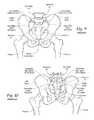
- the human hip girdle(see FIGS. 9 and 10 ) is made up of three large bones joined by three relatively immobile joints.
- One of the bonesis called the sacrum and it lies at the bottom of the lumbar spine, where it connects with the L5 vertebra.
- the other two bonesare commonly called “hip bones” and are technically referred to as the right ilium and the left ilium.
- the sacrumconnects with both hip bones at the sacroiliac joint (in shorthand, the SI-Joint).
- the SI-Jointfunctions in the transmission of forces from the spine to the lower extremities, and vice-versa.
- the SI-Jointhas been described as a pain generator for up to 22% of lower back pain.
- sacroiliac joint fusionis typically indicated as surgical treatment, e.g., for degenerative sacroiliitis, inflammatory sacroiliitis, iatrogenic instability of the sacroiliac joint, osteitis condensans ilii, or traumatic fracture dislocation of the pelvis.
- screw and screw with platesare used for sacro-iliac fusion.
- the cartilagehas to be removed from the “synovial joint” portion of the SI joint. This requires a large incision to approach the damaged, subluxed, dislocated, fractured, or degenerative joint.
- the inventionprovides bone fixation/fusion systems, devices, and related methods for stabilizing adjacent bone segments in a minimally invasive manner.
- the adjacent bone segmentscan comprise parts of the same bone that have been fractured, or two or more individual bones separated by a space or joint.
- bone segmentsor “adjacent bone regions” refer to either situation, i.e., a fracture line in a single bone (which the devices serve to fixate), or a space or joint between different bone segments (which the devices serve to arthrodese or fuse).
- the devicescan therefore serve to perform a fixation function between two or more individual bones, or a fusion function between two or more parts of the same bone, or both functions.
- One aspect of the inventionprovides assemblies and associated methods for the fixation or fusion of bone structures comprising first and second bone segments separated by a fracture line or joint.
- the assemblies and associated methodscomprise an anchor body sized and configured to be introduced into the first and second bone segments.
- the anchor bodyhas a distal end located in an interior region of the second bone segment; a proximal end located outside an exterior region of the first bone segment; and an intermediate region spanning the fracture line or joint between the first and second bone segments.
- the assemblies and associated methodsalso include a distal anchor secured to the interior region of the second bone segment and affixed to the distal end of the anchor body to anchor the distal end in the second bone segment.
- the assemblies and associated methodsfurther include a proximal anchor secured to the exterior region of the first bone segment and affixed to the proximal end of the anchor body, which, in concert with the distal anchor, places the anchor body in compression to compress and fixate the bone segments relative to the fracture line or joint.
- the assemblies and associated methodsalso include an elongated implant structure carried by the intermediate region of the anchor body and spanning the fracture line or joint between the bone segments.
- the elongated implant structureincludes an exterior surface region treated to provide bony in-growth or through-growth along the implant structure, to accelerate the fixation or fusion of the first and second bone segments held in compression and fixated by the anchor body.
- the bone fixation/fusion systems, devices, and related methodsare well suited for stabilizing adjacent bone segments in the SI-Joint.
- another aspect of the inventionprovides a method for the fusion of the sacral-iliac joint between an iliac and a sacrum.
- the methodcomprises creating an insertion path through the ilium, through the sacral-iliac joint, and into the sacrum.
- the methodincludes providing an anchor body sized and configured to be introduced through the insertion path laterally into the ilium and sacrum.
- the anchor bodyhas a distal end sized and configured to be located in an interior region of the sacrum; a proximal end sized and configured to be located outside an exterior region of the iliac; and an intermediate region sized and configured to span the sacral-iliac joint.
- the methodincludes providing an elongated implant structure sized and configured to be passed over the anchor body to span the sacral-iliac joint between the iliac and sacrum.
- the elongated implant structureincludes an exterior surface region treated to provide bony in-growth or through-growth along the implant structure.
- the methodincludes introducing the anchor body through the insertion path from the ilium, through the sacral-iliac joint, and into the sacrum.
- the methodincludes anchoring the distal end of the anchor body in the interior region of the sacrum.
- the methodincludes passing the elongated implant structure over the anchor body to span the sacral-iliac joint between the ilium and sacrum, and anchoring the proximal end of the anchor body to an exterior region of the ilium, which, in concert with the anchored distal end, places the anchor body in compression to compress and fixate the sacral-iliac joint.
- the bony in-growth or through-growth region of the implant structureaccelerates the fixation or fusion of the sacral-iliac joint held in compression and fixated by the anchor body.
- FIG. 1is a side section view of a compression stem assembly assembled in adjacent bone regions, which are shown in FIG. 1 in a diagrammatically fashion for the purpose of illustration, without anatomic detail, which is later shown, e.g., in FIG. 16 .
- FIG. 2is an exploded perspective view of the components of the compression stem assembly shown in FIG. 1 prior to assembly.
- FIGS. 3 to 7are alternative embodiments of an implant structure which forms a part of the compression stem assembly shown in FIGS. 1 and 2 , illustrating different cross-sectional geometries and configurations for the implant structure 20 .
- FIGS. 8A to 8Lare side section views of the introduction and assembly of the compression stem assembly shown in FIGS. 1 and 2 , which is shown in FIGS. 8A to 8L in a diagrammatically fashion for the purpose of illustration, without anatomic detail, as later shown, e.g., in FIG. 16 .
- FIGS. 9 and 10are, respectively, anterior and posterior anatomic views of the human hip girdle comprising the sacrum and the hip bones (the right ilium, and the left ilium), the sacrum being connected with both hip bones at the sacroiliac joint (in shorthand, the SI-Joint).
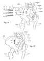
- FIGS. 11 to 13A and 13Bare anatomic views showing, respectively, in exploded perspective, assembled perspective, assembled anterior view, and assembled axial section view, the implantation of three implant structures, without association of a compression stem assembly, for the fixation of the SI-Joint using a lateral approach laterally through the ilium, the SI-Joint, and into the sacrum S 1 .
- FIGS. 14 to 16A and 16Bare anatomic views showing, respectively, in exploded perspective, assembled perspective, assembled anterior view, and assembled axial section view, the implantation of three implant structures, in association with a compression stem assembly, for the fixation of the SI-Joint using a lateral approach laterally through the ilium, the SI-Joint, and into the sacrum S 1 .
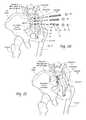
- FIGS. 17 to 19A and 19Bare anatomic views showing, respectively, in exploded perspective, assembled perspective, assembled lateral view, and assembled axial section view, the implantation of three implant structures, without association of a compression stem assembly, for the fixation of the SI-Joint using a postero-lateral approach entering from the posterior iliac spine of the ilium, angling through the SI-Joint, and terminating in the sacral alae.
- FIGS. 20 to 22A and 22Bare anatomic views showing, respectively, in exploded perspective, assembled perspective, assembled lateral view, and assembled axial section view, the implantation of three implant structures, in association with a compression stem assembly, for the fixation of the SI-Joint using a postero-lateral approach entering from the posterior iliac spine of the ilium, angling through the SI-Joint, and terminating in the sacral alae.
- FIGS. 23 and 24A and 24Bare anatomic views showing, respectively, in exploded perspective, assembled anterior view, and assembled axial section view, the implantation of a screw-like structure for the fixation of the SI-Joint using a lateral approach laterally through the ilium, the SI-Joint, and into the sacrum S 1 .
- FIGS. 25 and 26A and 26Bare anatomic views showing, respectively, in exploded perspective, assembled lateral view, and assembled axial section view, the implantation of a screw-like structure for the fixation of the SI-Joint using a postero-lateral approach entering from the posterior iliac spine of the ilium, angling through the SI-Joint, and terminating in the sacral alae.
- FIGS. 27 and 28A and 28Bare anatomic views showing, respectively, in exploded perspective, assembled anterior view, and assembled axial section view, the implantation of a fusion cage structure for the fixation of the SI-Joint using a lateral approach laterally through the ilium, the SI-Joint, and into the sacrum S 1 .
- FIGS. 29 and 30A and 30Bare anatomic views showing, respectively, in exploded perspective, assembled lateral view, and assembled axial section view, the implantation of a fusion cage structure for the fixation of the SI-Joint using a postero-lateral approach entering from the posterior iliac spine of the ilium, angling through the SI-Joint, and terminating in the sacral alae.
- FIG. 31is an exploded perspective view of the components of an alternative embodiment of a compression stem assembly prior to assembly.
- FIGS. 32 and 33are perspective views of the alternative embodiment of a compression stem assembly shown in FIG. 31 after assembly, showing rotation of an anchor plate associated with the assembly from an aligned position ( FIG. 32 ) to a bone-gripping position (shown in FIG. 33 ), to anchor the assembly in bone.
- FIG. 34is a side section view of the compression stem assembly shown in FIG. 31 assembled in adjacent bone regions, which are shown in FIG. 34 in a diagrammatically fashion for the purpose of illustration, without anatomic detail.
- FIGS. 35A and 35Bare side section views of an alternative embodiment of a compression stem assembly prior to assembly ( FIG. 35A ) and after assembly ( FIG. 35B ) in adjacent bone regions, which are shown in FIGS. 35A and 35B in a diagrammatically fashion for the purpose of illustration, without anatomic detail.
- FIGS. 36A and 36Bare side section views of a radially compressible implant prior to assembly ( FIG. 36A ) and after assembly ( FIG. 36B ) in adjacent bone regions, which are shown in FIGS. 36A and 36B in a diagrammatically fashion for the purpose of illustration, without anatomic detail.
- FIGS. 1 and 2show in assembled and exploded views, respectively, a representative configuration of a compression stem assembly 10 sized and configured for the fixation of bone fractures (i.e., fixation of parts of the same bone) or for the fixation of bones which are to be fused (arthrodesed) (i.e. fixation of two or more individual bones that are adjacent and/or jointed).
- the assembly 10will sometimes be called a bone fixation/fusion compression assembly, to indicate that it can perform a fixation function between two or more individual bones), or a fusion function between two or more parts of the same bone, or both functions.
- bone segmentsor “adjacent bone regions” refer to either situation, i.e., a fracture line in a single bone or a space or joint between different bone segments.
- FIG. 1the bone segment or adjacent bone regions are shown diagrammatically without anatomic detail for the purpose of illustration. Later, e.g., in FIGS. 13 to 16 and FIGS. 20 to 22 , the bone segments or adjacent bone regions are shown in a specific anatomic setting, comprising the joint between the sacrum and the ilium of the pelvis, also anatomically called the sacroiliac joint (SI-Joint).
- SI-Jointsacroiliac joint
- the compression stem assembly 10comprises an anchor body 12 , which (as shown in FIG. 1 ) is sized and configured to be placed in compression within bone segments or adjacent bone regions.
- the anchor body 12takes the form of a cylindrical anchor pin or rod. Still, the anchor body 12 can possess other geometries.
- the anchor body 12is anchored at a distal end to a distal anchor screw 14 coupled to an interior bone region in one side of the space or joint.
- the anchor body 12is secured at a proximal end, on the opposite side of the space or joint, to an exterior bone region by an anchor nut 16 and anchor washer 18 .
- the distal anchor screw 14 and anchor nut 16hold the anchor body 12 in compression and, in doing so, the anchor body 12 compresses and fixates the bone segments or adjacent bone regions.
- the anchor body 12carries within the bone regions or segments an elongated, stem-like, cannulated implant structure 20 .
- the implant structure 20includes an interior bore 22 that accommodates its placement by sliding over the anchor body 12 .
- the implant structure 20includes a region 24 formed along at least a portion of its length to promote bony in-growth onto or into surface of the structure and/or bony growth entirely through all or a portion of the structure.
- the bony-in-growth or through-growth region 24 along the surface of the implant structure 20accelerates bony in-growth or through-growth onto, into, or through the implant structure 20 .
- Bony in-growth or through-growth onto, into, or through the implant structure 20helps speed up the fusion process or fracture healing time of the bone segments or adjacent bone regions held in compression and fixated by the anchor body 12 .
- the anchor body 12 , nut 16 , and washer 18can be formed—e.g., by machining, molding, or extrusion—from a material usable in the prosthetic arts that is capable of being placed into and holding compressive forces and that is not subject to significant bio-absorption or resorption by surrounding bone or tissue over time.
- the anchor body 12 , nut 16 , and washer 18are intended to remain in place for a time sufficient to stabilize the fracture or fusion site. Examples of such materials include, but are not limited to, titanium, titanium alloys, tantalum, chrome cobalt, surgical steel, or any other total joint replacement metal and/or ceramic, sintered glass, artificial bone, any uncemented metal or ceramic surface, or a combination thereof.
- the anchor body 12is sized to span a distance through one adjacent bone segment or region, through the intervening space or joint, and at least partially into the other adjacent bone segment or region.
- the anchor body 12is sized on length and diameter according to the local anatomy.
- the morphology of the local structurescan be generally understood by medical professionals using textbooks of human skeletal anatomy along with their knowledge of the site and its disease or injury. The physician is also able to ascertain the dimensions of the anchor body 12 based upon prior analysis of the morphology of the targeted bone region using, for example, plain film x-ray, fluoroscopic x-ray, or MRI or CT scanning.
- a representative diameter for the anchor body 12can range between 3.2 mm to 3.5 mm.
- the proximal and distal regions of the anchor body 12include external helical ridges or screw threads 26 and 28 formed around the cylindrical body of the anchor body 12 .
- the anchor body 12if desired, can be threaded substantially along its entire length.
- the direction of the screw threads 26 and 28is the same at both proximal and distal regions of the anchor body 12 , e.g., they desirably comprise right-hand threads.
- the proximal region of the anchor body 12 carrying the threads 26is sized to extend, in use, a distance outside the one adjacent bone segment or region. In this way, the proximal region is, in use, exposed so that the proximal anchor nut 16 and washer 18 can be attached.
- the anchor nut 16includes complementary internal screw threads that are sized and configured to mate with the external screw threads 26 on the proximal region of the anchor body 12 .
- Representative diameters for an anchor nut 16 and anchor washer 18 for a 3.2 mm anchor body 12are, respectively, 3.2 mm and 8 mm.
- the distal region of the anchor body 12 carrying the threads 28is sized to extend at least partially into the other adjacent bone segment or region, where it is to be coupled to the anchor screw 14 , as will next be described.
- the anchor screw 14can likewise be formed—e.g., by machining, or molding—from a durable material usable in the prosthetic arts that is capable of being screwed into bone and that is not subject to significant bio-absorption or resorption by surrounding bone or tissue over time.
- the anchor screw 14like the other components of the compression assembly 10 , is intended to remain in place for a time sufficient to stabilize the fracture or fusion site. Examples of such materials include, but are not limited to, titanium, titanium alloys, tantalum, chrome cobalt, surgical steel, or any other total joint replacement metal and/or ceramic, or a combination thereof.
- the anchor screw 14is sized to span a distance within the other adjacent bone segment or region at the terminus of the threaded distal region 28 of the anchor body 12 .
- the anchor screw 14includes external helical ridges or screw threads 30 formed around the cylindrical body of the anchor screw 14 .
- the external screw threads 30are sized and configured to gain purchase in bone when rotated, so that the anchor screw 14 can be advanced and seated by rotation into bone in the bone segment or region.
- the anchor screw 14seated within the bone, resists axial migration and separation.
- a representative range of lengths for the anchor screw 14can be between 5 mm to 20 mm, again depending upon the demands of the local anatomy.
- a representative diameter for the anchor screw 14is about 7 mm.
- the anchor screw 14also includes internal helical ridges or screw threads 32 formed within a bore in the anchor screw 14 .
- the internal screw threads 32are sized and configured to mate with the complementary external screw threads 28 on the distal region of the anchor body 12 .
- the anchor screw 14anchors the distal region of the anchor body 12 to bone to resists axial migration of the anchor body 12 .
- the anchor screw 14 (on the distal end) and the anchor nut 16 and anchor washer 18 (on the proximal end)hold the anchor body 12 in compression, thereby compressing and fixating the bone segments or adjacent bone regions.
- an internally threaded component free external screw threadscan be is sized and configured to be securely affixed within the broached bore in the most distal bone segment where the broached bore terminates, e.g., by making an interference fit and/or otherwise being secured by the use of adhesives.
- the interference fit and/or adhesivesanchor the overall implant structure. Adhesives may also be used in combination with the anchor screw 14 .
- the implant structure 20can be formed—e.g., by machining, molding, or extrusion—from a durable material usable in the prosthetic arts that is not subject to significant bio-absorption or resorption by surrounding bone or tissue over time.
- the implant structure 20like the other components of the compression assembly 10 , is intended to remain in place for a time sufficient to stabilize the fracture or fusion site.
- Such materialsinclude, but are not limited to, titanium, titanium alloys, tantalum, tivanium (aluminum, vanadium, and titanium), chrome cobalt, surgical steel, or any other total joint replacement metal and/or ceramic, sintered glass, artificial bone, any uncemented metal or ceramic surface, or a combination thereof.
- the implant structure 20may be formed from a suitable durable biologic material or a combination of metal and biologic material, such as a biocompatible bone-filling material.
- the implant structure 20may be molded from a flowable biologic material, e.g., acrylic bone cement, that is cured, e.g., by UV light, to a non-flowable or solid material.
- the implant structure 20is sized according to the local anatomy.
- the morphology of the local structurescan be generally understood by medical professionals using textbooks of human skeletal anatomy along with their knowledge of the site and its disease or injury.
- the physicianis also able to ascertain the dimensions of the implant structure 20 based upon prior analysis of the morphology of the targeted bone region using, for example, plain film x-ray, fluoroscopic x-ray, or MRI or CT scanning.
- the implant structure 20can take various shapes and have various cross-sectional geometries.
- the implant structure 20can have, e.g., a generally curvilinear (i.e., round or oval) cross-section—as FIG. 3 shows for purposes of illustration—or a generally rectilinear cross section (i.e., square or rectangular or triangular—as FIG. 4 shows for purposes of illustration—or combinations thereof.
- the implant structure 20is shown to be triangular in cross section, which effectively resists rotation and micromotion once implanted.
- the implant structure 20can include a tapered region 34 at least along a portion of its axial length, meaning that the width or diameter of the implant structure 20 incrementally increases along its axial length.
- the tapered region 34corresponds with, in use, the proximal region of the implant structure 20 (i.e., the last part of the implant structure 20 to enter bone).
- the amount of the incremental increase in width or diametercan vary. As an example, for an implant structure 20 having a normal diameter of 7 mm, the magnitude of the incremental increase at its maximum can range between about 0.25 mm to 1.25 mm.
- the tapered region 34further enhances the creation and maintenance of compression between the bone segments or regions.
- the implant structure 20can include projecting bone-gripping surfaces 36 in the form of “teeth” or wings or the like.
- the teeth or wings 36can project, e.g., 2 to 4 mm from the surface of the implant structure 20 and face in the direction of the compression forces at proximal and distal ends of the implant structure 20 , taking purchase into the bone segments as they are compressed together by the compression assembly.
- the bony in-growth or through-growth region 24may extend along the entire outer surface of the implant structure 20 , as shown in FIG. 1 or 2 , or the bony in-growth or through-growth region 24 may cover just a specified distance on either side of the bone segments or fracture line.
- the bony in-growth region 24 or through-growthcan comprise, e.g., through holes, and/or various surface patterns, and/or various surface textures, and/or pores, or combinations thereof.
- the configuration of the bony in-growth or through-growth region 24can, of course, vary.
- the bony in-growth or through-growth region 24can comprise an open mesh configuration; or beaded configuration; or a trabecular configuration; or include holes or fenestrations. Any configuration conducive to bony in-growth and/or bony through-growth will suffice.
- the bony in-growth or through-growth region 24can be coated or wrapped or surfaced treated to provide the bony in-growth or through-growth region, or it can be formed from a material that itself inherently possesses a structure conducive to bony in-growth or through-growth, such as a porous mesh, hydroxyapetite, or other porous surface.
- the bony in-growth or through-growth regioncan include holes that allow bone to grow throughout the region.
- the bony in-growth region or through-growth region 24comprises a porous plasma spray coating on the implant structure 20 . This creates a biomechanically rigorous fixation/fusion system, designed to support reliable fixation/fusion and acute weight bearing capacity.
- the bony in-growth or through-growth region 24may further be covered with various other coatings such as antimicrobial, antithrombotic, and osteoinductive agents, or a combination thereof.
- the entire implant structure 20may be impregnated with such agents, if desired.
- FIGS. 8A to 8Ldiagrammatically, show for purposes of illustration, a representative procedure for implanting a compression stem assembly 10 . More detailed, anatomically-focused descriptions of particular implantation techniques of the compression stem assembly 10 in the SI-Joint will be described later.
- the physicianidentifies the bone segments or adjacent bone regions that are to be fixated or fused (arthrodesed) (see FIG. 8A ). Aided by conventional visualization techniques, e.g., using X-ray image intensifiers such as a C-arms or fluoroscopes to produce a live image feed which is displayed on a TV screen, a guide pin 38 is introduced by conventional means (see FIG. 8B ) through the one adjacent bone segment or region, through the intervening space or joint, and partially into the other adjacent bone segment or region.
- X-ray image intensifierssuch as a C-arms or fluoroscopes
- a cannulated drill bit 40is passed over the guide pin 38 (see FIG. 8C ), to form a pilot insertion path or bore 42 through the one adjacent bone segment or region, through the intervening space or joint, and partially into the other adjacent bone segment or region.
- a single drill bit or multiple drill bits 40can be employed to drill through bone fragments or bone surfaces to create a pilot bore 42 of the desired size and configuration.
- a region of bone distal to the pilot bore 42is left undrilled and native for seating of the anchor screw 14 .
- the pilot bore 42is completed, the cannulated drill bit 40 is removed.
- a broach 44 having the external geometry and dimensions matching the external geometry and dimensions of the implant structure 20(which, in the illustrated embodiment, is triangular) (see FIG. 8D ) is tapped over the guide pin 38 through the pilot bore 42 .
- the shaped broach 44cuts along the edges of the pilot bore 42 to form the desired profile (which, in the illustrated embodiment, is triangular) to accommodate the implant structure 20 through the one adjacent bone segment or region, through the intervening space or joint, and partially into the other adjacent bone segment or region.
- the broach 44is withdrawn (see FIG. 8E ), and the anchor screw 14 (its internal screw threads 32 mated to the distal end of a cannulated threaded screw driver 46 ) is passed over the guide pin 38 to the terminus of the broached bore 48 in the distal bone segment.
- the anchor screw 14is threaded by operation of the screw driver 46 (see FIG. 8F ) into the undrilled and native bone beyond the terminus of the broached bore 48 .
- the anchor screw 14can be advanced and buried in bone at least 5 mm beyond the terminus of the broached bore 48 .
- the threaded screw driver 46is unthreaded by reverse rotation from the anchor screw 14 , and the guide pin 38 is removed (see FIG. 8G ).
- the anchor body 12is inserted, and its threaded distal end 28 is threaded into and mated with the internal screw threads 32 of the anchor screw 14 (see FIG. 8H ).
- the implant structure 20is passed over the anchor body 12 by sliding it over the anchor body 12 .
- the length of the implant structure 20 selectedis less than the distance between the anchor screw 14 and the threaded proximal end 26 , such that, when initially inserted and before compression is applied to the anchor body 26 , the distal end of the implant structure 20 is spaced from the proximal end of the anchor screw 14 (see FIG. 8I ).
- the distancecan range, e.g., between about 4 mm to about 10 mm.
- the anchor washer 18is passed by sliding over the exposed threaded proximal end 26 of the anchor body 12 into abutment against an exterior bone surface (see FIG. 8J ).
- the anchor nut 16is threaded onto and mated to the threaded proximal end 26 of the anchor body 12 (see FIG. 8K ).
- the anchor nut 16is tightened against the anchor washer 18 using a hand (or powered) chuck 50 (see FIG. 8L ), until a desired amount of compression is applied to the bone regions by the assembly 10 .
- the compressionwill reduce the distance between the bone segments (as FIGS.
- more than one compression stem assembly 10can be implanted in a given bone segment.
- three such compression stem assembliescan be implanted to fuse a SI-Joint.
- FIGS. 31 to 33An alternative embodiment for the compression stem assembly 10 is shown in FIGS. 31 to 33 .
- the compression stem assembly 10is sized and configured to be implanted in adjoining bone segments, which are separated by a space or joint, for the purpose of bone fixation or joint fusion, as already described.
- the anchor body 12 , nut 16 , and washer 18are sized and configured as previously described.
- the implant structure 20is sized and configured with a generally rectilinear cross section, as also earlier described and shown in FIG. 4 .
- the distal end of the assembly 10is anchored into bone by a generally rectilinear anchor plate 58 .
- the anchor plate 58is formed—e.g., by machining, or molding—from a hard, durable material usable in the prosthetic arts that is capable of cutting into and gaining purchase in bone, and that is not subject to significant bio-absorption or resorption by surrounding bone or tissue over time.
- the rectilinear anchor plate 58is sized and configured to match the rectilinear cross section of the implant structure itself.
- the implant structure 20is generally triangular in cross section, and so, too, is the anchor plate 58 .
- the anchor plate 58includes apexes 64 .
- the sides of the anchor plate 58 between the apexesare sharpened to comprise bone cutting edges 72 .
- the anchor plate 58also includes a bore 60 in its geometric center (see FIG. 31 ). Internal helical ridges or screw threads 62 are formed within the bore 68 . The internal screw threads 62 are sized and configured to mate with the complementary external screw threads 28 on the distal region of the anchor body 12 . The distal region of the anchor body 12 can thereby be threaded to the anchor plate 58 (as shown in FIG. 32 ). When threaded to the anchor body 12 , the anchor plate 58 rotates in common with the anchor body 12 (as shown in FIG. 33 ).
- the anchor body 12Prior to introduction of the implant structure 20 into the broached bore 48 formed in the manner previously described (and as shown in FIGS. 8A to 8D ), the anchor body 12 is passed through the bore 22 of the implant structure 20 , and the anchor plate 58 is threaded to the distal threaded region 26 of the anchor body 12 , which is sized to project beyond the distal end of the implant structure 20 . Further, as FIG. 32 shows, the anchor plate 58 is additionally rotationally oriented in a position aligned with the distal end of the implant structure 20 . In the aligned position ( FIG. 32 ), the apexes 64 of the anchor plate 58 overlay and register with the apexes 66 of the distal end of the implant structure 20 .
- the implant structure 20 , anchor body 12 , and anchor plate 58are introduced as a unit through the broached bore 48 in the orientation shown in FIG. 32 .
- the anchor plate 58offers no resistance to passage of the implant structure 20 through the broached bore 48 .
- the proximal end of the anchor body 58Upon contacting the terminus of the broached bore, the proximal end of the anchor body 58 is rotated 60.degree. degrees (as shown in FIG. 33 ). The rotation moves the anchor plate 58 into an extended, bone-gripping position not longer aligned with the distal end of the implant structure 20 (as is shown in FIG. 33 ). In the extended, bone-gripping position, the apexes 64 of the triangular anchor plate 58 project radially outward from the triangular sides 68 of the implant structure 20 . The anchor plate 58 presents at the distal end of the implant structure 20 an enlarged lateral surface area, larger than the cross sectional area of the implant structure itself.
- the cutting edges 72 of the anchor plate 58advance into bone and cut bone, seating the anchor plate 58 into bone in the bone segment or region (see FIG. 34 ).
- the anchor plate 58anchors the distal end of the anchor body 12 into bone.
- the anchor plate 58resists axial migration and separation, in much the same fashion as the anchor screw 14 .
- the sides 68 of the implant structure 20 at the distal end of the structure 20preferably include cut-outs 70 (see FIGS. 31 and 32 ).
- the cut-outs 70are sized and configured so that, when the anchor plate 58 is rotated into its bone-gripping position, the body of the anchor plate 58 adjoining the apexes detents and comes to rest within the cut outs 70 , as FIG. 33 shows. Nested within the cut-outs 70 , further tightening of the anchor nut 16 and washer 18 at the proximal end of the anchor body 12 , as previously described, locks the anchor plate 58 in the bone-gripping, anchored position.
- FIGS. 35A and 35BAn alternative embodiment of a compressible implant structure is shown in FIGS. 35A and 35B .
- the implant structureis sized and configured to be implanted in adjoining bone segments, which are separated by a space or joint, for the purpose of bone fixation or joint fusion, as already described.
- the implant structurecan possess a circular or curvilinear cross section, as previously described.
- the implant structure 20 shown in FIG. 35Acomprises two mating implant components 74 and 78 .
- each implant component 74and can be formed—e.g., by machining, molding, or extrusion—from a durable material usable in the prosthetic arts that is not subject to significant bio-absorption or resorption by surrounding bone or tissue over time.
- Each implant component 74 and 78includes exterior bony in-growth or through-growth regions, as previously described.
- a broached boreis formed through the bone segments in the manner previously described, and is shown in FIGS. 8A to 8D .
- the implant component 74is sized and configured to be securely affixed within the broached bore in the most distal bone segment where the broached bore terminates, e.g., by making an interference fit and/or otherwise being secured by the use of adhesives.
- the implant component 74is intended to anchor the overall implant structure.
- the implant component 74further includes a post 76 that extends through the broached bore into the most proximal bone segment, where the broached bore originates.
- the post 76includes internal threads 80 .
- the second implant component 78is sized and configured to be introduced into the broached bore of the most proximal bone segment.
- the second implant componentincludes an interior bore, so that the implant component 78 is installed by sliding it over the post 76 of the first implant component 74 , as FIG. 35B shows.
- An anchor screw 16(desirably with a washer 18 ) includes external screw threads, which are sized and configured to mate with the complementary internal screw threads 80 within the post 76 . Tightening the anchor screw 16 draws the first and second implant components 74 and 78 together, reducing the space or joint between the first and second bone segments and putting the resulting implant structure into compression, as FIG. 35B shows.
- FIGS. 36A and 36BAn alternative embodiment of an implant structure 82 is shown in FIGS. 36A and 36B .
- the implant structure 82is sized and configured to be implanted in adjoining bone segments, which are separated by a space or joint, for the purpose of bone fixation or joint fusion, as already described.
- the implant structure 82is sized and configured to be placed into radial compression.
- the implant structure 82includes a body that can possess a circular or curvilinear cross section, as previously described. As before described, the implant structure 82 can be formed—e.g., by machining, molding, or extrusion—from a durable material usable in the prosthetic arts that is not subject to significant bio-absorption or resorption by surrounding bone or tissue over time.
- the implant structure 82includes one or more exterior bony in-growth or through-growth regions, as previously described.
- the proximal end of the implant structure 82includes an axial region of weakness comprising a split 84 .
- a self-tapping screw 16is included.
- the screw 16includes a tapered threaded body.
- the tapered bodyforms a wedge of increasing diameter in the direction toward the head of the screw 16 .
- the screw 16is self-tapping, being sized and configured to be progressively advanced when rotated into the split 84 , while creating its own thread, as FIG. 36B shows.
- a broached boreis formed through the bone segments in the manner previously described, and as shown in FIGS. 8A to 8D .
- the implant structure 84is introduced into the broached bore, as FIG. 36A shows.
- the implant structureis desirably sized and configured to be securely affixed within the broached bore in the most distal bone segment where the broached bore terminates, e.g., by making an interference fit and/or otherwise being secured by the use of adhesives.
- the interference fit and/or adhesivesanchor the overall implant structure 84 .
- the self-tapping screw 16(desirably with a washer 18 ) is progressively advanced by rotation into the split 84 .
- the wedge-shape of the threaded body of the screw 16progressively urges the body of the implant structure 84 to expand axially outward along the split 84 , as FIG. 36B shows.
- the expansion of the diameter of the body of the implant structure 82 about the split 84presses the proximal end of the implant structure 82 into intimate contact against adjacent bone.
- the radial expansion of the body of the implant structure 82 about the split 84radially compresses the proximal end of the implant structure 82 against bone.
- the radial compressionassures intimate contact between the bony in-growth region and bone within the broached bore, as well as resists both rotational and axial migration of the implant structure 82 within the bone segments.
- an elongated, stem-like, implant structure 20 having a bony in-growth and/or through-growth regioncan be sized and configured for the fixation of bone fractures (i.e., fixation of parts of the same bone) or for the fixation of bones which are to be fused (arthrodesed) throughout the body without association with a compression stem assembly 10 as just described, or without other means for achieving compression of the implant structure as just described.
- Elongated, stem-like implant structures 20 like that shown in FIG. 2make possible the fixation of the SI-Joint (shown in anterior and posterior views, respectively, in FIGS. 9 and 10 ) in a minimally invasive manner, with or without association with a compression stem assembly 10 .
- These implant structures 20can be effectively implanted through the use of two alternative surgical approaches; namely, (i) a Lateral Approach, or (ii) a Postero-Lateral Approach.
- A-Panterior-posterior
- one or more implant structures 20are introduced (without use of a compression stem assembly 10 ) laterally through the ilium, the SI-Joint, and into the sacrum S 1 .
- This path and resulting placement of the implant structures 20are best shown in FIGS. 12 and 13A /B.
- three implant structures 20are placed in this manner.
- the implant structures 20are triangular in cross section, but it should be appreciated that implant structures 20 of other cross sections as previously described can be used.
- the physicianBefore undertaking a lateral implantation procedure, the physician identifies the SI-Joint segments that are to be fixated or fused (arthrodesed) using, e.g., the Faber Test, or CT-guided injection, or X-ray/MRI of SI Joint.
- the physicianAided by lateral and anterior-posterior (A-P) c-arms, and with the patient lying in a prone position (on their stomach), the physician aligns the greater sciatic notches (using lateral visualization) to provide a true lateral position.
- a 3 cm incisionis made starting aligned with the posterior cortex of the sacral canal, followed by blood-tissue separation to the ilium.
- the guide pin 38(with sleeve) (e.g., a Steinmann Pin) is started resting on the ilium at a position inferior to the sacrum S 1 end plate and just anterior to the sacral canal.
- the guide pin 38In A-P and lateral views, the guide pin 38 should be parallel to the S 1 end plate at a shallow angle anterior (e.g., 15.degree. to 20.degree. off horizontal, as FIG. 13A shows). In a lateral view, the guide pin 38 should be posterior to the sacrum anterior wall. In the A-P view, the guide pin 38 should be superior to the S 1 inferior foramen and lateral of mid-line. This corresponds generally to the sequence shown diagrammatically in FIGS. 8A and 8B .
- a soft tissue protector(not shown) is desirably slipped over the guide pin 38 and firmly against the ilium before removing the guide pin 38 sleeve.
- the pilot bore 42is drilled in the manner previously described, as is diagrammatically shown in FIG. 8C .
- the pilot bore 42extends through the ilium, through the SI-Joint, and into the S 1 .
- the drill bit 40is removed.
- the shaped broach 44is tapped into the pilot bore 42 over the guide pin 38 (and through the soft tissue protector) to create a broached bore 48 with the desired profile for the implant structure 20 , which, in the illustrated embodiment, is triangular. This generally corresponds to the sequence shown diagrammatically in FIG. 8D .
- the triangular profile of the broached bore 48is also shown in FIG. 11 .
- a triangular implant structure 20can be now tapped (in this embodiment, without an associated compression sleeve assembly) through the soft tissue protector over the guide pin 38 through the ilium, across the SI-Joint, and into the S 1 , until the proximal end of the implant structure 20 is flush against the lateral wall of the ilium (see also FIGS. 13A and 13B ).
- the guide pin 38 and soft tissue protectorare withdrawn, leaving the implant structure 20 residing in the broached passageway, flush with the lateral wall of the ilium (see FIGS. 13A and 13B ).
- two additional implant structures 20are implanted in this manner, as FIG. 12 best shows.
- the implant structures 20are sized according to the local anatomy.
- representative implant structures 20can range in size, depending upon the local anatomy, from about 35 mm to about 55 mm in length, and about 7 mm diameter.
- the morphology of the local structurescan be generally understood by medical professionals using textbooks of human skeletal anatomy along with their knowledge of the site and its disease or injury. The physician is also able to ascertain the dimensions of the implant structure 20 based upon prior analysis of the morphology of the targeted bone using, for example, plain film x-ray, fluoroscopic x-ray, or MRI or CT scanning.
- the lateral approachalso lends itself to the introduction of one or more implant structures 20 in association with compression stem assemblies 10 , as previously described, laterally through the ilium, the SI-Joint, and into the sacrum S 1 .
- This path and resulting placement of the implant structuresare best shown in FIGS. 16A and 16B .
- three implant structures 20are placed in this manner.
- the implant structuresare triangular in cross section, but it still should be appreciated that implant structures having other cross sections, as previously described, can be used.
- the implant structure 20is not inserted immediately following the formation of the broached bore 48 . Instead, components of the compression stem assembly 10 are installed first in the broached bore 48 to receive the implant structure 20 .
- the guide pin 38is removed, while keeping the soft tissue protector in place.
- the anchor screw 14 of the compression stem assembly 10is seated in bone in the sacrum S 1 beyond the terminus of the broached bore 48 , in the manner generally shown in FIGS. 8E to 8G .
- an extent of bone in the sacrum S 1is left native and undrilled beyond the terminus of the pilot bore 42 and broached bore 48 .
- the anchor screw 14is advanced and buried in this extent of native and undrilled bone in the sacrum S 1 , as FIGS. 16A and 16B show, to be coupled to the threaded distal end 28 of the anchor body 12 .
- the threaded proximal end 28 of the anchor body 12is threaded into and mated to the anchor screw 14 within the sacrum S 1 , as previously described and as shown in FIG. 8H , with the remainder of the anchor body 12 extending proximally through the SI-Joint and ilium, to project an exposed distance outside the lateral wall of the ilium, as FIGS. 16A and 16B show.
- the implant structure 20is then placed by sliding it over the anchor body 12 , until flush against the lateral wall of the ilium, as previously described and as shown in FIG. 8I .
- the anchor washer 18 and nutare then installed and tightened on the proximal end of the anchor body 12 , as previously described and shown in FIGS. 8J to 8L , putting the assembly into compression.
- the resulting assemblyis shown in FIGS. 15 and 16A /B.
- three compression stem assemblies 10can be installed by lateral approach across the SI-Joint. As individual compression stem assemblies are placed into compression by tightening the anchor nut 16 , the implant structures of neighboring compression stem assemblies may advance to project slightly beyond the lateral wall of the ilium. If this occurs, the projecting implant structures 20 can be gently tapped further into the ilium over their respective anchor pins 12 .
- one or more implant structurescan be introduced (without use of a compression stem assembly 10 ) in a postero-lateral approach entering from the posterior iliac spine of the ilium, angling through the SI-Joint, and terminating in the sacral alae.
- This path and resulting placement of the implant structures 20are best shown in FIGS. 18 and 19A /B.
- three implant structures 20are placed in this manner.
- the implant structures 20are triangular in cross section, but it should be appreciated that implant structures 20 of other cross sections as previously described can be used.
- the postero-lateral approachinvolves less soft tissue disruption that the lateral approach, because there is less soft tissue overlying the entry point of the posterior iliac spine of the ilium. Introduction of the implant structure 20 from this region therefore makes possible a smaller, more mobile incision. Further, the implant structure 20 passes through more bone along the postero-lateral route than in a strictly lateral route, thereby involving more surface area of the SI-Joint and resulting in more fusion and better fixation of the SI-Joint. Employing the postero-lateral approach also makes it possible to bypass all nerve roots, including the L5 nerve root.
- the set-up for a postero-lateral approachis generally the same as for a lateral approach. It desirably involves the identification of the SI-Joint segments that are to be fixated or fused (arthrodesed) using, e.g., the Faber Test, or CT-guided injection, or X-ray/MRI of SI Joint. It is desirable performed with the patient lying in a prone position (on their stomach) and is aided by lateral and anterior-posterior (A-P) c-arms.
- A-Panterior-posterior
- pilot bore 42is formed over a guide pin 38 , except the path of the pilot bore 42 now starts from the posterior iliac spine of the ilium, angles through the SI-Joint, and terminates in the sacral alae.
- the pilot bore 42is shaped into the desired profile using a broach, as before described (shown in FIG. 17 ), and the implant structure 20 is inserted into the broached bore 48 the manner shown in FIGS. 18 and 19A /B.
- the triangular implant structure 20is tapped (in this embodiment, without an associated compression sleeve assembly 10 ) through the soft tissue protector over the guide pin 38 from the posterior iliac spine of the ilium, angling through the SI-Joint, and terminating in the sacral alae, until the proximal end of the implant structure 20 is flush against the posterior iliac spine of the ilium, as FIG. 18 shows.
- FIGS. 17 to 19A /Bthree implant structures 20 are introduced in this manner. Because of the anatomic morphology of the bone along the postero-lateral route, it may be advisable to introduce implant structures of difference sizes, with the most superior being the longest in length, and the others being smaller in length.
- the postero-lateral approachalso lends itself to the introduction of one or more implant structures 20 in association with compression stem assemblies 10 , as previously described, entering from the posterior iliac spine of the ilium, angling through the SI-Joint, and advancing into the sacral alae.
- This path and resulting placement of the implant structures 20 with compression stem assemblies 10are best shown in FIGS. 22A /B.
- three implant structures 20are placed in this-manner. Also, as in the embodiment shown in FIGS.
- the implant structures 20are triangular in cross section, but it still should be appreciated that implant structures 20 of other cross sections as previously described can be used.
- the implant structure 20is not inserted immediately following the formation of the broached bore 48 . Instead, components of the compression stem assembly 10 are installed in the broached bore 48 first to receive the implant structure 20 , as have been previously described as is shown in FIG. 20 .
- the set-up for a postero-lateral approachis generally the same as for a lateral approach. It is desirable performed with the patient lying in a prone position (on their stomach) and is aided by lateral and anterior-posterior (A-P) c-arms.
- A-Panterior-posterior
- the same surgical toolsare used to form the pilot bore 42 over a guide pin 38 that starts from the posterior iliac spine of the ilium, angles through the SI-Joint, and terminates in the sacral alae.
- the pilot bore 42is shaped into the desired profile using a broach 44 , as before described (and as shown in FIG. 20 ).
- an extent of bone in the sacral alaeis left native and undrilled beyond the terminus of the formed pilot bore 42 and broached bore 48 .
- the anchor screw 14is advanced and buried in this extent of native and undrilled bone in the sacral alae, as FIGS. 22A /B show, to be coupled to the threaded distal end 28 of the anchor body 12 . Due to the morphology of the sacral alae, the anchor screw 14 may be shorter than it would be if buried in the sacrum S 1 by the lateral approach.
- the threaded proximal end 28 of the anchor body 12is threaded into and mated to the anchor screw 14 within the sacral alae, as previously described and as shown in FIG. 8H , with the remainder of the anchor body 12 extending proximally through the SI-Joint to project an exposed distance outside the superior iliac spine of the ilium, as FIGS. 21 to 22A /B show.
- the implant structure 20is then placed by sliding it over the anchor body 12 , until flush against the superior iliac spine of the ilium, as previously described and as shown in FIG. 8I .
- the anchor washer 18 and nutare then installed and tightened on the proximal end of the anchor body 12 , as previously described and shown in FIGS. 8J to 8L , putting the assembly 10 into compression.
- the resulting assembly 10is shown in FIGS. 21 and 22A /B.
- three compression stem assemblies 10can be installed by postero-lateral approach across the SI-Joint. As before explained, as individual compression stem assemblies 10 are placed into compression by tightening the anchor nut 16 , the implant structures 20 of neighboring compression stem assemblies 10 may advance to project slightly beyond the superior iliac spine of the ilium. If this occurs, the projecting implant structures 20 can be gently tapped further into the superior iliac spine of the ilium over their respective anchor bodies 12 .
- one or more implant structures 20can be individually inserted in a minimally invasive fashion, with or without association of compression stem assemblies 10 , or combinations thereof, across the SI-Joint, as has been described.
- Conventional tissue access tools, obturators, cannulas, and/or drillscan be used for this purpose. No joint preparation, removal of cartilage, or scraping are required before formation of the insertion path or insertion of the implant structures 20 , so a minimally invasive insertion path sized approximately at or about the maximum outer diameter of the implant structures 20 need be formed.
- the implant structures 20with or without association of compression stem assemblies 10 , obviate the need for autologous bone graft material, additional pedicle screws and/or rods, hollow modular anchorage screws, cannulated compression screws, threaded cages within the joint, or fracture fixation screws.
- implant structures 20might be needed, depending on the size of the patient and the size of the implant structures 20 .
- the patientwould be advised to prevent loading of the SI-Joint while fusion occurs. This could be a six to twelve week period or more, depending on the health of the patient and his or her adherence to post-op protocol.
- the implant structures 20make possible surgical techniques that are less invasive than traditional open surgery with no extensive soft tissue stripping.
- the lateral approach and the postero-lateral approach to the SI-Jointprovide straightforward surgical approaches that complement the minimally invasive surgical techniques.
- the profile and design of the implant structures 20minimize rotation and micromotion.
- Rigid implant structures 20 made from titaniumprovide immediate post-op SI Joint stability.
- a bony in-growth region 24 comprising a porous plasma spray coating with irregular surfacesupports stable bone fixation/fusion.
- the implant structures 20 and surgical approachesmake possible the placement of larger fusion surface areas designed to maximize post-surgical weight bearing capacity and provide a biomechanically rigorous implant designed specifically to stabilize the heavily loaded SI-Joint.
- the Lateral Approach and the Postero-Lateral Approach to the SI-Jointaided by conventional lateral and/or anterior-posterior (A-P) visualization techniques, make possible the fixation of the SI-Joint in a minimally invasive manner using other forms of fixation/fusion structures. Either approach makes possible minimal incision size, with minimal soft tissue stripping, minimal tendon irritation, less pain, reduced risk of infection and complications, and minimal blood loss.
- A-Panterior-posterior
- one or more screw-like structures 52e.g., a hollow modular anchorage screw, or a cannulated compression screw, or a fracture fixation screw, can be introduced using the lateral approach described herein, being placed laterally through the ilium, the SI-Joint, and into the sacrum S 1 .
- This path and resulting placement of the screw-like structures 52are shown in FIGS. 23 and 24A /B.
- the screw-like structurecarry a bony in-growth material or a bony through-growth configuration, as described, as well as being sized and configured to resist rotation after implantation.
- one or more of the screw-like structures 52can be introduced using the postero-lateral approach described herein, entering from the posterior iliac spine of the ilium, angling through the SI-Joint, and terminating in the sacral alae. This path and resulting placement of the screw-like structure are shown in FIGS. 25 and 26A /B.
- the screw-like structures 52carry a bony in-growth material or a bony through-growth configuration, as described, as well as being sized and configured to resist rotation after implantation, as before described.
- one or more fusion cage structures 54 containing bone graft materialcan be introduced using the lateral approach described herein, being placed laterally through the ilium, the SI-Joint, and into the sacrum S 1 .
- This path and resulting placement of the fusion cage structures 54are shown in FIGS. 27 and 28A /B.
- Such a structure 54may include an anchor screw component 56 , to be seated in the sacrum S 1 , as shown in FIGS. 27 and 28A /B.
- one or more of the fusion cage structures 54can be introduced using the postero-lateral approach described herein, entering from the posterior iliac spine of the ilium, angling through the SI-Joint, and terminating in the sacral alae. This path and resulting placement of the fusion cage structures 54 are shown in FIGS. 29 and 30A /B.
- Such a structure 54may include an anchor screw component 56 , to be seated in the sacral alae, as shown in FIGS. 27 and 28A /B.
Landscapes
- Health & Medical Sciences (AREA)
- Orthopedic Medicine & Surgery (AREA)
- Life Sciences & Earth Sciences (AREA)
- Surgery (AREA)
- Biomedical Technology (AREA)
- Engineering & Computer Science (AREA)
- Veterinary Medicine (AREA)
- Heart & Thoracic Surgery (AREA)
- Animal Behavior & Ethology (AREA)
- General Health & Medical Sciences (AREA)
- Public Health (AREA)
- Medical Informatics (AREA)
- Molecular Biology (AREA)
- Nuclear Medicine, Radiotherapy & Molecular Imaging (AREA)
- Neurology (AREA)
- Oral & Maxillofacial Surgery (AREA)
- Dentistry (AREA)
- Cardiology (AREA)
- Transplantation (AREA)
- Vascular Medicine (AREA)
- Neurosurgery (AREA)
- Prostheses (AREA)
- Surgical Instruments (AREA)
Abstract
Description
Claims (9)
Priority Applications (7)
| Application Number | Priority Date | Filing Date | Title |
|---|---|---|---|
| US14/274,486US9486264B2 (en) | 2004-08-09 | 2014-05-09 | Systems and methods for the fixation or fusion of bone using compressive implants |
| US15/195,955US9949843B2 (en) | 2004-08-09 | 2016-06-28 | Apparatus, systems, and methods for the fixation or fusion of bone |
| US15/952,102US20180228621A1 (en) | 2004-08-09 | 2018-04-12 | Apparatus, systems, and methods for the fixation or fusion of bone |
| US16/930,174US12004961B2 (en) | 2005-05-24 | 2020-07-15 | Apparatus, systems, and methods for the fixation or fusion of bone |
| US16/932,001US11986397B2 (en) | 2005-05-24 | 2020-07-17 | Apparatus, systems, and methods for the fixation or fusion of bone |
| US16/933,108US20200345510A1 (en) | 2005-05-24 | 2020-07-20 | Apparatus, systems, and methods for the fixation or fusion of bone |
| US16/933,084US11633292B2 (en) | 2005-05-24 | 2020-07-20 | Apparatus, systems, and methods for the fixation or fusion of bone |
Applications Claiming Priority (6)
| Application Number | Priority Date | Filing Date | Title |
|---|---|---|---|
| US10/914,629US20060036251A1 (en) | 2004-08-09 | 2004-08-09 | Systems and methods for the fixation or fusion of bone |
| US11/136,141US7922765B2 (en) | 2004-08-09 | 2005-05-24 | Systems and methods for the fixation or fusion of bone |
| US12/924,784US8388667B2 (en) | 2004-08-09 | 2010-10-05 | Systems and methods for the fixation or fusion of bone using compressive implants |
| US12/924,782US8986348B2 (en) | 2004-08-09 | 2010-10-05 | Systems and methods for the fusion of the sacral-iliac joint |
| US13/786,037US8734462B2 (en) | 2004-08-09 | 2013-03-05 | Systems and methods for the fixation or fusion of bone using compressive implants |
| US14/274,486US9486264B2 (en) | 2004-08-09 | 2014-05-09 | Systems and methods for the fixation or fusion of bone using compressive implants |
Related Parent Applications (2)
| Application Number | Title | Priority Date | Filing Date |
|---|---|---|---|
| US13/786,037ContinuationUS8734462B2 (en) | 2004-08-09 | 2013-03-05 | Systems and methods for the fixation or fusion of bone using compressive implants |
| US13/858,814Continuation-In-PartUS9375323B2 (en) | 2004-08-09 | 2013-04-08 | Apparatus, systems, and methods for achieving trans-iliac lumbar fusion |
Related Child Applications (2)
| Application Number | Title | Priority Date | Filing Date |
|---|---|---|---|
| US10/914,629Continuation-In-PartUS20060036251A1 (en) | 2004-08-09 | 2004-08-09 | Systems and methods for the fixation or fusion of bone |
| US15/195,955Continuation-In-PartUS9949843B2 (en) | 2004-08-09 | 2016-06-28 | Apparatus, systems, and methods for the fixation or fusion of bone |
Publications (2)
| Publication Number | Publication Date |
|---|---|
| US20140249589A1 US20140249589A1 (en) | 2014-09-04 |
| US9486264B2true US9486264B2 (en) | 2016-11-08 |
Family
ID=57354022
Family Applications (6)
| Application Number | Title | Priority Date | Filing Date |
|---|---|---|---|
| US12/924,784Expired - LifetimeUS8388667B2 (en) | 2004-08-09 | 2010-10-05 | Systems and methods for the fixation or fusion of bone using compressive implants |
| US12/924,782Expired - LifetimeUS8986348B2 (en) | 2004-08-09 | 2010-10-05 | Systems and methods for the fusion of the sacral-iliac joint |
| US13/786,037Expired - LifetimeUS8734462B2 (en) | 2004-08-09 | 2013-03-05 | Systems and methods for the fixation or fusion of bone using compressive implants |
| US14/274,486Expired - LifetimeUS9486264B2 (en) | 2004-08-09 | 2014-05-09 | Systems and methods for the fixation or fusion of bone using compressive implants |
| US14/280,436Expired - LifetimeUS9039743B2 (en) | 2004-08-09 | 2014-05-16 | Systems and methods for the fusion of the sacral-iliac joint |
| US14/707,817Expired - Fee RelatedUS9662128B2 (en) | 2004-08-09 | 2015-05-08 | Systems and methods for the fusion of the sacral-iliac joint |
Family Applications Before (3)
| Application Number | Title | Priority Date | Filing Date |
|---|---|---|---|
| US12/924,784Expired - LifetimeUS8388667B2 (en) | 2004-08-09 | 2010-10-05 | Systems and methods for the fixation or fusion of bone using compressive implants |
| US12/924,782Expired - LifetimeUS8986348B2 (en) | 2004-08-09 | 2010-10-05 | Systems and methods for the fusion of the sacral-iliac joint |
| US13/786,037Expired - LifetimeUS8734462B2 (en) | 2004-08-09 | 2013-03-05 | Systems and methods for the fixation or fusion of bone using compressive implants |
Family Applications After (2)
| Application Number | Title | Priority Date | Filing Date |
|---|---|---|---|
| US14/280,436Expired - LifetimeUS9039743B2 (en) | 2004-08-09 | 2014-05-16 | Systems and methods for the fusion of the sacral-iliac joint |
| US14/707,817Expired - Fee RelatedUS9662128B2 (en) | 2004-08-09 | 2015-05-08 | Systems and methods for the fusion of the sacral-iliac joint |
Country Status (6)
| Country | Link |
|---|---|
| US (6) | US8388667B2 (en) |
| EP (1) | EP2624772B1 (en) |
| JP (2) | JP5771277B2 (en) |
| CN (1) | CN103237514B (en) |
| BR (1) | BR112013008227A2 (en) |
| WO (1) | WO2012048008A1 (en) |
Cited By (38)
| Publication number | Priority date | Publication date | Assignee | Title |
|---|---|---|---|---|
| US20180055521A1 (en)* | 2010-01-13 | 2018-03-01 | Jcbd, Llc | Methods of fusing a sacroiliac joint |
| US9956013B2 (en) | 2004-08-09 | 2018-05-01 | Si-Bone Inc. | Systems and methods for the fixation or fusion of bone |
| US10004547B2 (en) | 2004-08-09 | 2018-06-26 | Si-Bone Inc. | Systems and methods for the fixation or fusion of bone at or near a sacroiliac joint |
| US10194962B2 (en) | 2014-09-18 | 2019-02-05 | Si-Bone Inc. | Matrix implant |
| US10314710B2 (en) | 2010-01-13 | 2019-06-11 | Jcbd, Llc | Methods of fusing a sacroiliac joint |
| US10383664B2 (en) | 2013-07-30 | 2019-08-20 | Jcbd, Llc | Implants, systems, and methods for fusing a sacroiliac joint |
| US10433880B2 (en) | 2013-03-15 | 2019-10-08 | Jcbd, Llc | Systems and methods for fusing a sacroiliac joint and anchoring an orthopedic appliance |
| US10441318B2 (en) | 2010-01-13 | 2019-10-15 | Jcbd, Llc | Additively manufactured systems for low profile spinopelvic fixation and sacroiliac joint fusion for complex spinal deformities |
| US10492915B2 (en) | 2010-01-13 | 2019-12-03 | Jcbd, Llc | Sacroiliac joint fusion system |
| US10492802B2 (en) | 2013-07-30 | 2019-12-03 | Jcbd, Llc | Systems for and methods of preparing a sacroiliac joint for fusion |
| US10492688B2 (en) | 2014-05-27 | 2019-12-03 | Jcbd, Llc | Systems for and methods of diagnosing and treating a sacroiliac joint disorder |
| US10603055B2 (en) | 2017-09-15 | 2020-03-31 | Jcbd, Llc | Systems for and methods of preparing and fusing a sacroiliac joint |
| US10646236B2 (en) | 2010-01-13 | 2020-05-12 | Jcbd, Llc | Methods of fusing a sacroiliac joint with an additively manufactured sacroiliac joint implant |
| US20200345507A1 (en)* | 2005-05-24 | 2020-11-05 | Si-Bone Inc. | Apparatus, systems, and methods for the fixation or fusion of bone |
| US10952750B2 (en) | 2014-01-09 | 2021-03-23 | Surgalign Spine Technologies, Inc. | Undercutting system for use in conjunction with sacroiliac fusion |
| US10959758B2 (en) | 2013-03-15 | 2021-03-30 | Si-Bone Inc. | Implants for spinal fixation or fusion |
| US11116519B2 (en) | 2017-09-26 | 2021-09-14 | Si-Bone Inc. | Systems and methods for decorticating the sacroiliac joint |
| US11129655B2 (en) | 2018-07-20 | 2021-09-28 | Kic Ventures, Llc | System and method for bone fusing implants |
| US11147688B2 (en) | 2013-10-15 | 2021-10-19 | Si-Bone Inc. | Implant placement |
| US11173036B2 (en) | 2010-01-04 | 2021-11-16 | Surgalign Spine Technologies, Inc. | Sacroiliac fusion system |
| US11234830B2 (en) | 2019-02-14 | 2022-02-01 | Si-Bone Inc. | Implants for spinal fixation and or fusion |
| US11272967B2 (en) | 2018-07-11 | 2022-03-15 | Medline Industries, Lp | Bone plate system and method |
| US11291485B2 (en) | 2012-05-04 | 2022-04-05 | Si-Bone Inc. | Fenestrated implant |
| US11369419B2 (en) | 2019-02-14 | 2022-06-28 | Si-Bone Inc. | Implants for spinal fixation and or fusion |
| US11471286B2 (en) | 2012-03-09 | 2022-10-18 | Si-Bone Inc. | Systems, devices, and methods for joint fusion |
| USD967959S1 (en) | 2019-07-10 | 2022-10-25 | Medline Industries, Lp | Bone plate |
| US11571245B2 (en) | 2019-11-27 | 2023-02-07 | Si-Bone Inc. | Bone stabilizing implants and methods of placement across SI joints |
| US11684378B2 (en) | 2014-09-18 | 2023-06-27 | Si-Bone Inc. | Implants for bone fixation or fusion |
| US11752011B2 (en) | 2020-12-09 | 2023-09-12 | Si-Bone Inc. | Sacro-iliac joint stabilizing implants and methods of implantation |
| US11896211B2 (en) | 2019-09-11 | 2024-02-13 | Medline Industries, Lp | Orthopedic stabilization device, kit, and method |
| US11918474B2 (en) | 2005-12-06 | 2024-03-05 | The University Of Liverpool | Laser-produced porous surface |
| US12064154B2 (en) | 2019-07-18 | 2024-08-20 | Kic Ventures, Llc | System and method for bone fusing implants |
| US12083026B2 (en) | 2019-12-09 | 2024-09-10 | Si-Bone Inc. | Sacro-iliac joint stabilizing implants and methods of implantation |
| US12239310B2 (en) | 2022-04-27 | 2025-03-04 | Medline Industries, Lp | Orthopedic stabilization device, kit and method |
| US12419668B2 (en) | 2019-11-21 | 2025-09-23 | Si-Bone Inc. | Rod coupling assemblies for bone stabilization constructs |
| US12427028B2 (en) | 2018-03-28 | 2025-09-30 | Si-Bone Inc. | Threaded implants and methods of use across bone segments |
| US12433733B2 (en) | 2023-08-15 | 2025-10-07 | Si-Bone Inc. | Pelvic stabilization implants, methods of use and manufacture |
| US12433654B2 (en) | 2023-02-08 | 2025-10-07 | Medline Industries, Lp | Lisfranc reconstruction device, kit, and method |
Families Citing this family (169)
| Publication number | Priority date | Publication date | Assignee | Title |
|---|---|---|---|---|
| US7955357B2 (en) | 2004-07-02 | 2011-06-07 | Ellipse Technologies, Inc. | Expandable rod system to treat scoliosis and method of using the same |
| US9949843B2 (en) | 2004-08-09 | 2018-04-24 | Si-Bone Inc. | Apparatus, systems, and methods for the fixation or fusion of bone |
| US8444693B2 (en)* | 2004-08-09 | 2013-05-21 | Si-Bone Inc. | Apparatus, systems, and methods for achieving lumbar facet fusion |
| US8470004B2 (en) | 2004-08-09 | 2013-06-25 | Si-Bone Inc. | Apparatus, systems, and methods for stabilizing a spondylolisthesis |
| US8414648B2 (en)* | 2004-08-09 | 2013-04-09 | Si-Bone Inc. | Apparatus, systems, and methods for achieving trans-iliac lumbar fusion |
| US8388667B2 (en) | 2004-08-09 | 2013-03-05 | Si-Bone, Inc. | Systems and methods for the fixation or fusion of bone using compressive implants |
| US20060036251A1 (en) | 2004-08-09 | 2006-02-16 | Reiley Mark A | Systems and methods for the fixation or fusion of bone |
| US8425570B2 (en) | 2004-08-09 | 2013-04-23 | Si-Bone Inc. | Apparatus, systems, and methods for achieving anterior lumbar interbody fusion |
| WO2006034436A2 (en) | 2004-09-21 | 2006-03-30 | Stout Medical Group, L.P. | Expandable support device and method of use |
| FR2884406B1 (en) | 2005-04-14 | 2008-10-17 | Memometal Technologies Soc Par | INTRAMEDULAR OSTEOSYNTHESIS DEVICE OF TWO BONE PARTS, IN PARTICULAR HAND AND / OR FOOT |
| DE102005053819A1 (en)* | 2005-11-11 | 2007-05-16 | Khd Humboldt Wedag Gmbh | Rotary kiln burner |
| EP2023864B1 (en) | 2006-05-01 | 2019-07-10 | Stout Medical Group, L.P. | Expandable support device |
| US7862502B2 (en) | 2006-10-20 | 2011-01-04 | Ellipse Technologies, Inc. | Method and apparatus for adjusting a gastrointestinal restriction device |
| US11202707B2 (en) | 2008-03-25 | 2021-12-21 | Nuvasive Specialized Orthopedics, Inc. | Adjustable implant system |
| FR2935601B1 (en) | 2008-09-09 | 2010-10-01 | Memometal Technologies | INTRAMEDULLARY IMPLANT RESORBABLE BETWEEN TWO BONE OR TWO BONE FRAGMENTS |
| US8382756B2 (en) | 2008-11-10 | 2013-02-26 | Ellipse Technologies, Inc. | External adjustment device for distraction device |
| US20100211176A1 (en) | 2008-11-12 | 2010-08-19 | Stout Medical Group, L.P. | Fixation device and method |
| WO2010056895A1 (en) | 2008-11-12 | 2010-05-20 | Stout Medical Group, L.P. | Fixation device and method |
| US8349015B2 (en) | 2009-02-11 | 2013-01-08 | Howmedica Osteonics Corp. | Intervertebral implant with integrated fixation |
| US9241798B2 (en)* | 2009-03-20 | 2016-01-26 | David A. Petersen | Surgical methods and tools |
| US9622792B2 (en) | 2009-04-29 | 2017-04-18 | Nuvasive Specialized Orthopedics, Inc. | Interspinous process device and method |
| US9078701B2 (en)* | 2009-11-09 | 2015-07-14 | Centinel Spine, Inc. | System and method for stabilizing a posterior fusion over motion segments |
| US8348950B2 (en) | 2010-01-04 | 2013-01-08 | Zyga Technology, Inc. | Sacroiliac fusion system |
| WO2014015309A1 (en) | 2012-07-20 | 2014-01-23 | Jcbd, Llc | Orthopedic anchoring system and methods |
| EP2547292B1 (en) | 2010-03-16 | 2019-04-24 | Pinnacle Spine Group, LLC | Ntervertebral implants and graft delivery systems |
| US8900251B2 (en) | 2010-05-28 | 2014-12-02 | Zyga Technology, Inc | Radial deployment surgical tool |
| US9248043B2 (en) | 2010-06-30 | 2016-02-02 | Ellipse Technologies, Inc. | External adjustment device for distraction device |
| CA2806755C (en) | 2010-07-27 | 2018-07-10 | Richard S. Ginn | System for sacro-iliac stabilization |
| US12409039B2 (en)* | 2010-07-27 | 2025-09-09 | Tenon Medical, Inc. | Systems for sacroiliac joint stabilization |
| EP2608747A4 (en) | 2010-08-24 | 2015-02-11 | Flexmedex Llc | Support device and method for use |
| US9149286B1 (en) | 2010-11-12 | 2015-10-06 | Flexmedex, LLC | Guidance tool and method for use |
| US9138219B2 (en)* | 2010-12-29 | 2015-09-22 | Tarsus Medical Inc. | Methods and devices for treating a syndesmosis injury |
| WO2012112396A2 (en) | 2011-02-14 | 2012-08-23 | Ellipse Technologies, Inc. | Device and method for treating fractured bones |
| US9687278B2 (en)* | 2011-03-21 | 2017-06-27 | Ronald Childs | Sleeve for bone fixation device |
| US8900279B2 (en) | 2011-06-09 | 2014-12-02 | Zyga Technology, Inc. | Bone screw |
| EP2720628B1 (en) | 2011-06-17 | 2021-08-11 | Jcbd, Llc | Sacroiliac joint implant system |
| US8998925B2 (en) | 2011-06-20 | 2015-04-07 | Rdc Holdings, Llc | Fixation system for orthopedic devices |
| WO2012177759A1 (en) | 2011-06-20 | 2012-12-27 | Rdc Holdings, Llc | System and method for repairing joints |
| US9861411B2 (en) | 2011-06-28 | 2018-01-09 | Spinologics Inc. | Bone screw, and bone fixation system and method |
| US20130018427A1 (en)* | 2011-07-15 | 2013-01-17 | Khiem Pham | Screw Implants For Bone Fusion |
| US10925653B2 (en) | 2011-07-15 | 2021-02-23 | Globus Medical, Inc. | Screw implants for bone fusion |
| US10335216B2 (en) | 2011-07-15 | 2019-07-02 | Globus Medical, Inc. | Screw implants for bone fusion |
| FR2978343B1 (en)* | 2011-07-25 | 2013-08-23 | Medicrea International | ANCHORING BODY FOR VERTEBRAL OSTEOSYNTHESIS EQUIPMENT |
| EP2747682A4 (en) | 2011-08-23 | 2015-01-21 | Flexmedex Llc | Tissue removal device and method |
| US9113972B2 (en) | 2011-08-24 | 2015-08-25 | Pioneer Surgical Technology, Inc. | Apparatus and methods for immobilization and fusion of a synovial joint |
| US20130085535A1 (en)* | 2011-09-21 | 2013-04-04 | Flexmedex, LLC | Support device and method |
| US10743794B2 (en) | 2011-10-04 | 2020-08-18 | Nuvasive Specialized Orthopedics, Inc. | Devices and methods for non-invasive implant length sensing |
| WO2013052807A2 (en)* | 2011-10-05 | 2013-04-11 | H. Lee Moffitt Cancer Center And Research Institute, Inc. | Bone fusion system |
| US10799367B2 (en) | 2011-10-05 | 2020-10-13 | H. Lee Moffitt Cancer Center And Research Institute, Inc. | Bone fusion system |
| US9615856B2 (en)* | 2011-11-01 | 2017-04-11 | Imds Llc | Sacroiliac fusion cage |
| US10016220B2 (en) | 2011-11-01 | 2018-07-10 | Nuvasive Specialized Orthopedics, Inc. | Adjustable magnetic devices and methods of using same |
| US9380932B1 (en) | 2011-11-02 | 2016-07-05 | Pinnacle Spine Group, Llc | Retractor devices for minimally invasive access to the spine |
| US20130158610A1 (en)* | 2011-12-16 | 2013-06-20 | Depuy Mitek, Inc. | Bone graft fixation systems and methods |
| WO2013116452A2 (en) | 2012-01-31 | 2013-08-08 | The University Of Toledo | Bioactive fusion device |
| US20130245703A1 (en)* | 2012-03-02 | 2013-09-19 | Interventional Spine, Inc. | Method and apparatus for sacroiliac joint fixation |
| US20140276846A1 (en)* | 2013-03-15 | 2014-09-18 | Richard G. Mauldin | Systems and methods for implanting bone graft and implant |
| US8778026B2 (en) | 2012-03-09 | 2014-07-15 | Si-Bone Inc. | Artificial SI joint |
| US9044321B2 (en) | 2012-03-09 | 2015-06-02 | Si-Bone Inc. | Integrated implant |
| WO2013134678A1 (en)* | 2012-03-09 | 2013-09-12 | Si-Bone Inc. | Threaded implant |
| US20140012340A1 (en)* | 2012-07-05 | 2014-01-09 | Warsaw Orthopedic, Inc. | Sacro-iliac joint implant system and method |
| CN103536348A (en)* | 2012-07-10 | 2014-01-29 | 北京爱康宜诚医疗器材股份有限公司 | Integration anchoring bone nail |
| US20140031934A1 (en)* | 2012-07-26 | 2014-01-30 | Warsaw Orthopedic, Inc. | Sacro-iliac joint implant system and method |
| US9295488B2 (en) | 2012-08-09 | 2016-03-29 | Wilson T. Asfora | Joint fusion |
| US20140067069A1 (en) | 2012-08-30 | 2014-03-06 | Interventional Spine, Inc. | Artificial disc |
| DE202012103384U1 (en) | 2012-09-05 | 2012-09-24 | Signus Medizintechnik Gmbh | Pelvic ring implant |
| EP2911616B1 (en) | 2012-10-29 | 2020-10-07 | NuVasive Specialized Orthopedics, Inc. | Adjustable devices for treating arthritis of the knee |
| US9775648B2 (en)* | 2012-11-13 | 2017-10-03 | Louis E. Greenberg | Orthopedic implant having non-circular cross section and method of use thereof |
| US20140188179A1 (en)* | 2012-12-27 | 2014-07-03 | Wright Medical Technology, Inc. | Percutaneous flaring hammertoe fixation implant and instrument |
| US9962190B2 (en) | 2013-01-15 | 2018-05-08 | Friedrich Müller | MTV implantation set |
| WO2014159739A1 (en) | 2013-03-14 | 2014-10-02 | Pinnacle Spine Group, Llc | Interbody implants and graft delivery systems |
| US9186155B2 (en)* | 2013-03-14 | 2015-11-17 | NuTech Spine, Inc. | Sacroiliac joint stabilization method |
| US10245087B2 (en) | 2013-03-15 | 2019-04-02 | Jcbd, Llc | Systems and methods for fusing a sacroiliac joint and anchoring an orthopedic appliance |
| WO2014145772A2 (en)* | 2013-03-15 | 2014-09-18 | Si-Bone Inc. | Long implant for sacroiliac joint fusion |
| US9700356B2 (en) | 2013-07-30 | 2017-07-11 | Jcbd, Llc | Systems for and methods of fusing a sacroiliac joint |
| US9510872B2 (en) | 2013-03-15 | 2016-12-06 | Jcbd, Llc | Spinal stabilization system |
| US9119732B2 (en) | 2013-03-15 | 2015-09-01 | Orthocision, Inc. | Method and implant system for sacroiliac joint fixation and fusion |
| JP2015000208A (en)* | 2013-06-17 | 2015-01-05 | 株式会社ジーシー | Fracture part treatment member |
| CN105916458B (en)* | 2013-06-24 | 2019-09-27 | 托莱多大学 | Bioactive Fusion Devices |
| US9522028B2 (en) | 2013-07-03 | 2016-12-20 | Interventional Spine, Inc. | Method and apparatus for sacroiliac joint fixation |
| DE102013107881A1 (en) | 2013-07-23 | 2015-01-29 | Aesculap Ag | System for anchoring a pedicle screw, associated kit, spacer and Pedikelaugmentat |
| US9717538B2 (en)* | 2013-09-16 | 2017-08-01 | Spinefrontier, Inc | System and method for bone fusing implants and implant insertion tools |
| US10751094B2 (en) | 2013-10-10 | 2020-08-25 | Nuvasive Specialized Orthopedics, Inc. | Adjustable spinal implant |
| US9839448B2 (en)* | 2013-10-15 | 2017-12-12 | Si-Bone Inc. | Implant placement |
| WO2015095353A1 (en) | 2013-12-17 | 2015-06-25 | H. Lee Moffit Cancer Center And Research Institute, Inc. | Transdiscal screw |
| CN106456215B (en) | 2014-04-28 | 2020-04-10 | 诺威适骨科专科公司 | External adjustment device for adjusting a medical implant |
| WO2015168478A1 (en)* | 2014-05-01 | 2015-11-05 | Lorio Morgan Packard | Sacroiliac joint fastener, systems, and methods of using the same |
| US10064670B2 (en)* | 2014-05-12 | 2018-09-04 | DePuy Synthes Products, Inc. | Sacral fixation system |
| CA2949060A1 (en)* | 2014-05-12 | 2015-11-19 | DePuy Synthes Products, Inc. | Sacral fixation system |
| US10045803B2 (en) | 2014-07-03 | 2018-08-14 | Mayo Foundation For Medical Education And Research | Sacroiliac joint fusion screw and method |
| US10322009B2 (en) | 2014-08-01 | 2019-06-18 | H. Lee Moffitt Cancer Center And Research Institute, Inc. | Expandable intervertebral cage |
| US9907593B2 (en) | 2014-08-05 | 2018-03-06 | Woven Orthopedic Technologies, Llc | Woven retention devices, systems and methods |
| US10166022B2 (en) | 2014-09-29 | 2019-01-01 | Biomet C.V. | Method and apparatus for bone fixation |
| US9452056B2 (en)* | 2014-09-29 | 2016-09-27 | Biomet C.V. | Implants for fixation of the distal tibia |
| US10420652B2 (en) | 2014-10-09 | 2019-09-24 | Dr. Panagiotis Pedoulias | Bone scaffold improvements |
| US10383733B2 (en) | 2014-10-22 | 2019-08-20 | Biomet C.V. | Method and apparatus for bone fixation |
| US9974573B2 (en) | 2014-10-24 | 2018-05-22 | Mis Ip Holdings Llc | Minimally invasive approaches, methods and apparatuses to accomplish sacroiliac fusion |
| US9931141B2 (en) | 2014-11-26 | 2018-04-03 | Ex Technology, Llc | Method and apparatus for joint fusion |
| CN107530109B (en)* | 2014-12-22 | 2020-07-28 | 比肯生物医学有限公司 | Sacroiliac joint fusion systems and methods |
| ES2908064T3 (en) | 2014-12-26 | 2022-04-27 | Nuvasive Specialized Orthopedics Inc | distraction systems |
| AU2016200179B2 (en) | 2015-01-14 | 2020-09-17 | Stryker European Operations Holdings Llc | Spinal implant with porous and solid surfaces |
| AU2016200195B2 (en) | 2015-01-14 | 2020-07-02 | Vb Spine Us Opco Llc | Spinal implant with fluid delivery capabilities |
| US10238427B2 (en) | 2015-02-19 | 2019-03-26 | Nuvasive Specialized Orthopedics, Inc. | Systems and methods for vertebral adjustment |
| US9757168B2 (en) | 2015-03-03 | 2017-09-12 | Howmedica Osteonics Corp. | Orthopedic implant and methods of implanting and removing same |
| US9763800B2 (en)* | 2015-03-18 | 2017-09-19 | Biomet C. V. | Implant configured for hammertoe and small bone fixation |
| US10376206B2 (en) | 2015-04-01 | 2019-08-13 | Si-Bone Inc. | Neuromonitoring systems and methods for bone fixation or fusion procedures |
| JP6768001B2 (en) | 2015-04-29 | 2020-10-14 | インスティテュート フォー マスキュロスケレタル サイエンス アンド エジュケイション,リミテッド | Coiled implants and systems and how to make them |
| US10449051B2 (en) | 2015-04-29 | 2019-10-22 | Institute for Musculoskeletal Science and Education, Ltd. | Implant with curved bone contacting elements |
| US10492921B2 (en) | 2015-04-29 | 2019-12-03 | Institute for Musculoskeletal Science and Education, Ltd. | Implant with arched bone contacting elements |
| CA2930123A1 (en) | 2015-05-18 | 2016-11-18 | Stryker European Holdings I, Llc | Partially resorbable implants and methods |
| US10555758B2 (en) | 2015-08-05 | 2020-02-11 | Woven Orthopedic Technologies, Llc | Tapping devices, systems and methods for use in bone tissue |
| BR112018007347A2 (en) | 2015-10-16 | 2018-10-23 | Nuvasive Specialized Orthopedics, Inc. | adjustable devices for the treatment of knee arthritis |
| EP3367938A4 (en)* | 2015-10-27 | 2019-04-17 | Caploon, Konstantin, A. | AUTOCOMPRESSION IMPLANT |
| CN108601611B (en) | 2015-12-10 | 2021-11-02 | 诺威适骨科专科公司 | External adjustment device for stretcher |
| BR112018015504A2 (en) | 2016-01-28 | 2018-12-18 | Nuvasive Specialized Orthopedics, Inc. | bone transport systems |
| US10299837B2 (en) | 2016-03-08 | 2019-05-28 | West End Bay Partners, Llc | Sacroiliac joint stabilization and fixation devices and related methods |
| US9833321B2 (en) | 2016-04-25 | 2017-12-05 | Imds Llc | Joint fusion instrumentation and methods |
| US10413332B2 (en) | 2016-04-25 | 2019-09-17 | Imds Llc | Joint fusion implant and methods |
| EP3251621B1 (en) | 2016-06-03 | 2021-01-20 | Stryker European Holdings I, LLC | Intramedullary implant |
| EP3500218B1 (en) | 2016-06-23 | 2021-10-13 | Frank H. Boehm | Minimally invasive surgical systems for fusion of the sacroiliac joint |
| DE102016011947A1 (en)* | 2016-10-05 | 2018-04-05 | Bluewater Medical GmbH | Screw with a head part, a threaded part and a connecting part |
| US10478312B2 (en) | 2016-10-25 | 2019-11-19 | Institute for Musculoskeletal Science and Education, Ltd. | Implant with protected fusion zones |
| US11033394B2 (en) | 2016-10-25 | 2021-06-15 | Institute for Musculoskeletal Science and Education, Ltd. | Implant with multi-layer bone interfacing lattice |
| US10441317B2 (en) | 2016-10-26 | 2019-10-15 | SIGN Fracture Care International | Bone fixation system and method using a clamping instrument to guide fastener placement |
| US10667923B2 (en) | 2016-10-31 | 2020-06-02 | Warsaw Orthopedic, Inc. | Sacro-iliac joint implant system and method |
| WO2018107114A1 (en) | 2016-12-09 | 2018-06-14 | Woven Orthopedic Technologies, LLC. | Retention devices, lattices and related systems and methods |
| CN108236515A (en)* | 2016-12-23 | 2018-07-03 | 重庆润泽医药有限公司 | A kind of porous tantalum tantalum stick equipment |
| CN108236516A (en)* | 2016-12-23 | 2018-07-03 | 重庆润泽医药有限公司 | Porous tantalum tantalum stick equipment |
| CN108236519A (en)* | 2016-12-26 | 2018-07-03 | 重庆润泽医药有限公司 | For the tantalum bar device of operation |
| CN108236521A (en)* | 2016-12-26 | 2018-07-03 | 重庆润泽医药有限公司 | A kind of tantalum stick equipment for operation |
| CN108236523A (en)* | 2016-12-26 | 2018-07-03 | 重庆润泽医药有限公司 | For the tantalum bar system of operation |
| CN108236520A (en)* | 2016-12-26 | 2018-07-03 | 重庆润泽医药有限公司 | A kind of tantalum bar system for operation |
| CN108236522A (en)* | 2016-12-26 | 2018-07-03 | 重庆润泽医药有限公司 | A kind of tantalum bar device for operation |
| CN108236524A (en)* | 2016-12-26 | 2018-07-03 | 重庆润泽医药有限公司 | For the tantalum stick equipment of operation |
| CN108236525A (en)* | 2016-12-27 | 2018-07-03 | 重庆润泽医药有限公司 | A kind of bone surgery tantalum bar system |
| CN108245287A (en)* | 2016-12-28 | 2018-07-06 | 重庆润泽医药有限公司 | A kind of orthopedic operating tantalum stick equipment |
| CN108245286A (en)* | 2016-12-28 | 2018-07-06 | 重庆润泽医药有限公司 | A kind of orthopedic operating tantalum bar device |
| CN108245285A (en)* | 2016-12-28 | 2018-07-06 | 重庆润泽医药有限公司 | A kind of orthopedic operating tantalum bar system |
| CN108261267A (en)* | 2016-12-30 | 2018-07-10 | 重庆润泽医药有限公司 | Tantalum bar system with protection pipe |
| CN108261264A (en)* | 2016-12-30 | 2018-07-10 | 重庆润泽医药有限公司 | A kind of small-sized orthopedic operating tantalum bar device |
| CN108261265A (en)* | 2016-12-30 | 2018-07-10 | 重庆润泽医药有限公司 | A kind of small-sized orthopedic operating tantalum bar system |
| CN108261263A (en)* | 2016-12-30 | 2018-07-10 | 重庆润泽医药有限公司 | A kind of tantalum bar device with protection pipe |
| CN108261260A (en)* | 2016-12-30 | 2018-07-10 | 重庆润泽医药有限公司 | Small-sized orthopedic operating tantalum bar system |
| AU2018225123C1 (en) | 2017-02-21 | 2020-03-19 | Biomet Manufacturing, Llc | Implants for bridging osseous defects |
| US10512549B2 (en) | 2017-03-13 | 2019-12-24 | Institute for Musculoskeletal Science and Education, Ltd. | Implant with structural members arranged around a ring |
| US11452548B2 (en) | 2017-04-21 | 2022-09-27 | Stryker Corporation | Stabilization system, implant, and methods for preventing relative motion between sections of tissue |
| US20180303520A1 (en)* | 2017-04-21 | 2018-10-25 | Sharad Rajpal | Methods, implants, and tools for fusion of sacroiliac joints |
| AU2018265427B2 (en)* | 2017-05-12 | 2024-02-29 | Cutting Edge Spine Llc | Implants for tissue fixation and fusion |
| US11191645B2 (en)* | 2017-09-05 | 2021-12-07 | ExsoMed Corporation | Small bone tapered compression screw |
| US11147681B2 (en) | 2017-09-05 | 2021-10-19 | ExsoMed Corporation | Small bone angled compression screw |
| WO2019051260A1 (en) | 2017-09-08 | 2019-03-14 | Pioneer Surgical Technology, Inc. | Intervertebral implants, instruments, and methods |
| CN109481091A (en)* | 2017-09-13 | 2019-03-19 | 重庆润泽医药有限公司 | Tantalum stick |
| EP3459502B1 (en) | 2017-09-20 | 2024-05-22 | Stryker European Operations Holdings LLC | Spinal implants |
| USD907771S1 (en) | 2017-10-09 | 2021-01-12 | Pioneer Surgical Technology, Inc. | Intervertebral implant |
| US10744001B2 (en) | 2017-11-21 | 2020-08-18 | Institute for Musculoskeletal Science and Education, Ltd. | Implant with improved bone contact |
| US10940015B2 (en) | 2017-11-21 | 2021-03-09 | Institute for Musculoskeletal Science and Education, Ltd. | Implant with improved flow characteristics |
| US10864029B2 (en) | 2018-01-26 | 2020-12-15 | West End Bay Partners, Llc | Sacroiliac joint stabilization and fixation devices and related methods |
| DE102018113810A1 (en)* | 2018-06-11 | 2019-12-12 | Cortronik GmbH | Function marker element and method for its production |
| CN109363760A (en)* | 2018-10-19 | 2019-02-22 | 北京罗森博特科技有限公司 | A kind of hollow compression spike devices |
| US11564812B2 (en) | 2019-09-09 | 2023-01-31 | Warsaw Orthopedic, Inc. | Surgical instrument and method |
| US11344354B2 (en) | 2019-09-09 | 2022-05-31 | Warsaw Orthopedic, Inc. | Surgical instrument and method |
| US11154402B1 (en) | 2019-10-04 | 2021-10-26 | Pain TEQ, LLC | Instrumentation for fusing a sacroiliac joint |
| EP4037618A4 (en) | 2019-10-04 | 2023-12-13 | PTL Opco LLC | Allograft implant for fusing a sacroiliac joint |
| US11058550B2 (en) | 2019-10-04 | 2021-07-13 | Pain TEQ, LLC | Allograft implant for fusing a sacroiliac joint |
| TR2021015278A2 (en)* | 2021-09-30 | 2021-10-21 | Hakan Cici | ORTHOPEDIC EXPANDABLE BLADE SCREW ANCHOR SYSTEM |
| CN114028034A (en)* | 2021-11-10 | 2022-02-11 | 上海市第六人民医院 | An easy-to-install iliac wing filling block |
| US11931053B2 (en) | 2022-08-04 | 2024-03-19 | PTL Opco, LLC | Single-use joint decorticator apparatus |
| WO2024059246A2 (en)* | 2022-09-15 | 2024-03-21 | Sail Fusion, Llc | Sacroiliac fusion systems and methods |
| US12426926B2 (en) | 2022-12-06 | 2025-09-30 | Joseph Robbins | Hybrid approach methods for sacroiliac joint stabilization |
| US12295850B2 (en) | 2022-12-13 | 2025-05-13 | Spinal Simplicity, Llc | Systems, methods, and devices for lateral and posterior sacroiliac joint fusion |
Citations (395)
| Publication number | Priority date | Publication date | Assignee | Title |
|---|---|---|---|---|
| US1951278A (en) | 1932-02-13 | 1934-03-13 | Ericsson Ernst Axel Johan | Fracture nail |
| US2136471A (en) | 1937-06-30 | 1938-11-15 | Rudolph H Schneider | Bone pin |
| US2243717A (en) | 1938-09-20 | 1941-05-27 | Moreira Franciseo Elias Godoy | Surgical device |
| US2414882A (en) | 1943-09-24 | 1947-01-28 | Herschel Leiter H | Fracture reduction apparatus |
| US2562419A (en) | 1948-04-05 | 1951-07-31 | George L Ferris | Expansion nut setting tool |
| US2675801A (en) | 1954-04-20 | Intramedbllary nail | ||
| US2697433A (en) | 1951-12-04 | 1954-12-21 | Max A Zehnder | Device for accurately positioning and guiding guide wires used in the nailing of thefemoral neck |
| US3076453A (en) | 1961-01-16 | 1963-02-05 | Raymond G Tronzo | Hip nail |
| US3506982A (en) | 1965-06-21 | 1970-04-21 | Cleveland Clinic | Endoprosthetic joints |
| US3694821A (en) | 1970-11-02 | 1972-10-03 | Walter D Moritz | Artificial skeletal joint |
| US3709218A (en) | 1970-04-24 | 1973-01-09 | W Halloran | Combination intramedullary fixation and external bone compression apparatus |
| US4059115A (en) | 1976-06-14 | 1977-11-22 | Georgy Stepanovich Jumashev | Surgical instrument for operation of anterior fenestrated spondylodessis in vertebral osteochondrosis |
| US4156943A (en) | 1977-08-24 | 1979-06-05 | Collier John P | High-strength porous prosthetic device and process for making the same |
| US4292964A (en) | 1979-01-19 | 1981-10-06 | Ulrich Max B | Method of and apparatus for pinning a fractured pelvis |
| US4341206A (en) | 1978-12-19 | 1982-07-27 | Synthes Ag | Device for producing a hole in a bone |
| US4344190A (en) | 1979-07-25 | 1982-08-17 | University Of Exeter | Plugs for the medullary canal of a bone |
| US4399813A (en) | 1981-01-22 | 1983-08-23 | Barber Forest C | Apparatus and method for removing a prosthesis embedded in skeletal bone |
| US4423721A (en) | 1978-09-04 | 1984-01-03 | Schwarzkopf Development Corporation | Device for insertion and extraction of medullary nails |
| US4475545A (en) | 1982-12-06 | 1984-10-09 | Ender Hans G | Bone-nail |
| US4501269A (en) | 1981-12-11 | 1985-02-26 | Washington State University Research Foundation, Inc. | Process for fusing bone joints |
| US4569338A (en) | 1984-02-09 | 1986-02-11 | Edwards Charles C | Sacral fixation device |
| US4612918A (en) | 1984-10-16 | 1986-09-23 | Barclay Slocum | Method of eliminating canine cauda equina syndrome |
| US4622959A (en) | 1985-03-05 | 1986-11-18 | Marcus Randall E | Multi-use femoral intramedullary nail |
| US4630601A (en) | 1982-05-18 | 1986-12-23 | Howmedica International, Inc. | Bone nail for the treatment of fractures |
| US4638799A (en) | 1985-06-13 | 1987-01-27 | Moore Robert R | Needle guide apparatus for discolysis procedures |
| US4657550A (en) | 1984-12-21 | 1987-04-14 | Daher Youssef H | Buttressing device usable in a vertebral prosthesis |
| US4743256A (en) | 1985-10-04 | 1988-05-10 | Brantigan John W | Surgical prosthetic implant facilitating vertebral interbody fusion and method |
| US4773402A (en) | 1985-09-13 | 1988-09-27 | Isola Implants, Inc. | Dorsal transacral surgical implant |
| US4787378A (en) | 1986-09-08 | 1988-11-29 | Sodhi Jitendra S | Self-retaining nail for fracture of neck of femur |
| US4790303A (en) | 1987-03-11 | 1988-12-13 | Acromed Corporation | Apparatus and method for securing bone graft |
| US4834757A (en) | 1987-01-22 | 1989-05-30 | Brantigan John W | Prosthetic implant |
| US4846162A (en) | 1987-09-14 | 1989-07-11 | Moehring H David | Orthopedic nail and method of bone fracture fixation |
| US4877019A (en) | 1986-12-02 | 1989-10-31 | Pierre Vives | Intramedullary nail and apparatus for its insertion |
| US4898186A (en) | 1986-09-11 | 1990-02-06 | Gunze Limited | Osteosynthetic pin |
| US4904261A (en) | 1987-08-06 | 1990-02-27 | A. W. Showell (Surgicraft) Limited | Spinal implants |
| US4950270A (en) | 1989-02-03 | 1990-08-21 | Boehringer Mannheim Corporation | Cannulated self-tapping bone screw |
| US4961740A (en) | 1988-10-17 | 1990-10-09 | Surgical Dynamics, Inc. | V-thread fusion cage and method of fusing a bone joint |
| US4981481A (en) | 1987-10-06 | 1991-01-01 | Mecron Medizinische Produkte Gmbh | Marrow nail for the treatment of bone fractures according to the marrow cavity nailing procedure and marrow nail tool |
| US5034011A (en) | 1990-08-09 | 1991-07-23 | Advanced Spine Fixation Systems Incorporated | Segmental instrumentation of the posterior spine |
| US5035697A (en) | 1990-03-20 | 1991-07-30 | Synthes (U.S.A.) | Orthopedic medullary nail |
| US5041118A (en) | 1989-04-28 | 1991-08-20 | Implant Technology Inc. | Femoral broach |
| US5053035A (en) | 1990-05-24 | 1991-10-01 | Mclaren Alexander C | Flexible intramedullary fixation rod |
| US5059193A (en) | 1989-11-20 | 1991-10-22 | Spine-Tech, Inc. | Expandable spinal implant and surgical method |
| US5066296A (en) | 1989-02-02 | 1991-11-19 | Pfizer Hopsital Products Group, Inc. | Apparatus for treating a fracture |
| US5102414A (en) | 1988-12-10 | 1992-04-07 | Imz Fertigungs-Und Vertriebsgesellschaft Fur Dentale Technologie Mbh | Implantable fixing device for extraoral applications |
| US5108397A (en) | 1990-04-19 | 1992-04-28 | Joseph White | Method and apparatus for stabilization of pelvic fractures |
| US5122141A (en) | 1990-08-30 | 1992-06-16 | Zimmer, Inc. | Modular intramedullary nail |
| US5139498A (en) | 1988-10-18 | 1992-08-18 | Astudillo Ley Freddy R | Device for closing sternum in heart surgery |
| US5139500A (en) | 1989-05-08 | 1992-08-18 | Schwartz Nathan H | Bone attachment system |
| US5147367A (en) | 1991-02-22 | 1992-09-15 | Ellis Alfred B | Drill pin guide and method for orthopedic surgery |
| US5147402A (en) | 1990-12-05 | 1992-09-15 | Sulzer Brothers Limited | Implant for ingrowth of osseous tissue |
| US5190551A (en) | 1990-12-14 | 1993-03-02 | Zimmer, Inc. | Controlled apparatus and method for extracting cement mantles from bone recesses |
| US5197961A (en) | 1992-05-12 | 1993-03-30 | Castle Tris S | Toenail extender |
| JPH05176942A (en) | 1991-06-24 | 1993-07-20 | Howmedica Internatl Inc | Fracture fixture between intramedullary trochanter |
| US5242444A (en) | 1991-11-04 | 1993-09-07 | University Of Florida | Lumbosacral fixation and fusion method and device |
| US5298254A (en) | 1989-09-21 | 1994-03-29 | Osteotech, Inc. | Shaped, swollen demineralized bone and its use in bone repair |
| US5334205A (en)* | 1993-06-30 | 1994-08-02 | The United States Of America As Represented By The Secretary Of The Air Force | Sacroiliac joint fixation guide |
| US5380325A (en) | 1992-11-06 | 1995-01-10 | Biomat | Osteosynthesis device for spinal consolidation |
| US5390683A (en) | 1991-02-22 | 1995-02-21 | Pisharodi; Madhavan | Spinal implantation methods utilizing a middle expandable implant |
| US5433718A (en) | 1992-08-20 | 1995-07-18 | Brinker; Mark | Antibiotic eluding intramedullary nail apparatus |
| US5443466A (en) | 1991-12-13 | 1995-08-22 | Shah; Mrugesh K. | Method and apparatus for treating fractures of a bone |
| US5458638A (en) | 1989-07-06 | 1995-10-17 | Spine-Tech, Inc. | Non-threaded spinal implant |
| US5470334A (en) | 1991-03-05 | 1995-11-28 | Linvatec Corporation | Bioabsorbable interference bone fixation screw |
| US5480402A (en) | 1993-08-05 | 1996-01-02 | Kim; Andrew C. | Shoulder compression interlocking system |
| CN1128944A (en) | 1988-06-13 | 1996-08-14 | 卡林技术公司 | Apparatus and method of inserting spinal implants |
| US5569249A (en) | 1994-07-15 | 1996-10-29 | Smith & Nephew Richards Inc. | Cannulated modular intramedullary nail |
| US5591235A (en) | 1995-03-15 | 1997-01-07 | Kuslich; Stephen D. | Spinal fixation device |
| US5593409A (en) | 1988-06-13 | 1997-01-14 | Sofamor Danek Group, Inc. | Interbody spinal fusion implants |
| US5609636A (en) | 1994-05-23 | 1997-03-11 | Spine-Tech, Inc. | Spinal implant |
| US5626616A (en) | 1995-05-31 | 1997-05-06 | Speece; Conrad A. | Sacroiliac joint mobilization device |
| US5643264A (en) | 1995-09-13 | 1997-07-01 | Danek Medical, Inc. | Iliac screw |
| US5645599A (en) | 1994-07-26 | 1997-07-08 | Fixano | Interspinal vertebral implant |
| WO1997031517A2 (en) | 1995-03-27 | 1997-08-28 | Sdgi Holdings, Inc. | Spinal fusion implants and tools for insertion and revision |
| US5667510A (en) | 1995-08-03 | 1997-09-16 | Combs; C. Robert | Joint fixation system and method |
| US5669909A (en) | 1995-03-27 | 1997-09-23 | Danek Medical, Inc. | Interbody fusion device and method for restoration of normal spinal anatomy |
| US5672178A (en) | 1996-01-05 | 1997-09-30 | Petersen; Thomas D. | Fixation pin |
| US5683391A (en) | 1995-06-07 | 1997-11-04 | Danek Medical, Inc. | Anterior spinal instrumentation and method for implantation and revision |
| US5709683A (en) | 1995-12-19 | 1998-01-20 | Spine-Tech, Inc. | Interbody bone implant having conjoining stabilization features for bony fusion |
| US5713904A (en) | 1997-02-12 | 1998-02-03 | Third Millennium Engineering, Llc | Selectively expandable sacral fixation screw-sleeve device |
| US5716358A (en) | 1994-12-02 | 1998-02-10 | Johnson & Johnson Professional, Inc. | Directional bone fixation device |
| US5743912A (en) | 1995-08-23 | 1998-04-28 | Biomat | Upper femoral epiphysis osteosynthesis implant |
| US5759035A (en) | 1995-11-03 | 1998-06-02 | Ricci; Fernando | Bone fusion dental implant with hybrid anchor |
| US5766261A (en) | 1996-02-01 | 1998-06-16 | Osteonics Corp. | Femoral revision broach with modular trial components and method |
| US5766174A (en) | 1995-09-26 | 1998-06-16 | Orthologic Corporation | Intramedullary bone fixation device |
| US5788699A (en) | 1993-03-18 | 1998-08-04 | Endocare Ag | Drill section, as well as kirschner wires, bone routers and the like equipped with such a drill section |
| CN1190882A (en) | 1995-06-07 | 1998-08-19 | 加里·K·米切尔森 | Frusto-conical interbody spinal fusion implant |
| US5800440A (en) | 1997-03-18 | 1998-09-01 | Johnson & Johnson Professional, Inc. | Device for inserting a surgical pin |
| US5868749A (en) | 1996-04-05 | 1999-02-09 | Reed; Thomas M. | Fixation devices |
| US5928239A (en) | 1998-03-16 | 1999-07-27 | University Of Washington | Percutaneous surgical cavitation device and method |
| US5941885A (en) | 1996-10-08 | 1999-08-24 | Jackson; Roger P. | Tools for use in installing osteosynthesis apparatus utilizing set screw with break-off head |
| US5961554A (en) | 1996-12-31 | 1999-10-05 | Janson; Frank S | Intervertebral spacer |
| US5961522A (en) | 1997-11-10 | 1999-10-05 | Mehdizadeh; Hamid M. | Laminectomy chisel and guide apparatus |
| US6010507A (en) | 1998-07-24 | 2000-01-04 | Rudloff; David A. C. | Repair of bone fracture using flexible fully or partially cannulated compression/decompression fixation element |
| US6015409A (en) | 1994-05-25 | 2000-01-18 | Sdgi Holdings, Inc. | Apparatus and method for spinal fixation and correction of spinal deformities |
| US6053916A (en) | 1999-02-17 | 2000-04-25 | Moore; Michael R. | Sacroiliac implant |
| US6056749A (en) | 1999-03-15 | 2000-05-02 | Spineology, Inc. | Method and device for fixing and correcting spondylolisthesis anteriorly |
| US6086589A (en) | 1999-02-02 | 2000-07-11 | Spineology, Inc. | Method and device for fixing spondylolisthesis posteriorly |
| US6096080A (en) | 1998-05-06 | 2000-08-01 | Cortek, Inc. | Apparatus for spinal fusion using implanted devices |
| US6120504A (en) | 1998-12-10 | 2000-09-19 | Biomet Inc. | Intramedullary nail having dual distal bore formation |
| US6143031A (en) | 1995-10-20 | 2000-11-07 | Synthes (U.S.A.) | Intervertebral implant with compressible shaped hollow element |
| US6197062B1 (en) | 1999-01-11 | 2001-03-06 | Howmedica Osteonics, Corp. | Modular shoulder prosthesis system |
| US6210442B1 (en) | 1996-07-15 | 2001-04-03 | Aesculap Ag & Co. Kg | Implant for vertebral body fusion |
| US6214049B1 (en) | 1999-01-14 | 2001-04-10 | Comfort Biomedical, Inc. | Method and apparatus for augmentating osteointegration of prosthetic implant devices |
| US6221074B1 (en) | 1999-06-10 | 2001-04-24 | Orthodyne, Inc. | Femoral intramedullary rod system |
| US6224607B1 (en) | 1999-01-25 | 2001-05-01 | Gary K. Michelson | Instrumentation and method for creating an intervertebral space for receiving an implant |
| US6241732B1 (en) | 1998-11-03 | 2001-06-05 | David W. Overaker | Biocompatible absorbable rivets and pins for use in surgical procedures |
| US6264657B1 (en) | 1998-04-21 | 2001-07-24 | Depuy Acromed, Inc. | Method for removing devices from bone |
| US6270528B1 (en) | 1998-08-06 | 2001-08-07 | Sdgi Holdings, Inc. | Composited intervertebral bone spacers |
| US20010012942A1 (en) | 1998-04-09 | 2001-08-09 | Estes Bradley T. | Method and instrumentation for posterior interbody fusion |
| US6302885B1 (en) | 1998-01-15 | 2001-10-16 | Holger K. Essiger | Bone nail |
| US6302914B1 (en) | 1995-06-07 | 2001-10-16 | Gary Karlin Michelson | Lordotic interbody spinal fusion implants |
| US6306140B1 (en) | 2001-01-17 | 2001-10-23 | Synthes (Usa) | Bone screw |
| US6319253B1 (en) | 1998-03-05 | 2001-11-20 | Synthes (U.S.A) | Intramedullary nail with locking hole |
| US20010046518A1 (en) | 1998-08-14 | 2001-11-29 | Amarpreet S. Sawhney | Methods of using in situ hydration of hydrogel articles for sealing or augmentation of tissue or vessels |
| US20010047207A1 (en) | 1998-10-30 | 2001-11-29 | Michelson Gary K. | Self-broaching, rotatable, push-in interbody spinal fusion implant and method for deployment thereof |
| US20010049529A1 (en) | 1996-11-12 | 2001-12-06 | Cachia Victor V. | Bone fixation system |
| US20020038123A1 (en) | 2000-09-20 | 2002-03-28 | Visotsky Jeffrey L. | Osteotomy implant |
| US20020049497A1 (en) | 2000-10-11 | 2002-04-25 | Mason Michael D. | Graftless spinal fusion device |
| US20020077641A1 (en) | 1988-06-13 | 2002-06-20 | Michelson Gary Karlin | Apparatus and method of inserting spinal implants |
| US6409768B1 (en) | 2000-03-16 | 2002-06-25 | Slobodan Tepic | Screw anchored joint prosthesis |
| US20020082598A1 (en) | 2000-06-23 | 2002-06-27 | Teitelbaum George P. | Percutaneous vertebral fusion system |
| US20020087161A1 (en)* | 2001-01-03 | 2002-07-04 | Randall Bernard L. | Cannulated locking screw system especially for transiliac implant |
| WO2002038054A3 (en) | 2000-11-10 | 2002-07-04 | Biedermann Motech Gmbh | Bone screw |
| US20020120275A1 (en) | 2001-02-26 | 2002-08-29 | Arthrex, Inc. | Torque driver for interference screw |
| US20020128652A1 (en) | 1999-12-03 | 2002-09-12 | Ferree Bret A. | Version with markings to show changes made |
| US6451020B1 (en) | 1997-01-02 | 2002-09-17 | St. Francis Medical Technologies, Inc. | Spine distraction implant and method |
| US20020143334A1 (en) | 2001-03-30 | 2002-10-03 | Hoffmann Gerard Von | Method and apparatus for bone fixation with secondary compression |
| US20020151903A1 (en) | 2001-04-12 | 2002-10-17 | Asahi Kogaku Kogyo Kabushiki Kaisha | Surgical instrument |
| US6471707B1 (en) | 2001-05-11 | 2002-10-29 | Biomet | Bone screw having bioresorbable proximal shaft portion |
| US6485518B1 (en) | 1999-12-10 | 2002-11-26 | Nuvasive | Facet screw and bone allograft intervertebral support and fusion system |
| US20020183858A1 (en) | 2001-06-05 | 2002-12-05 | Contiliano Joseph H. | Attachment of absorbable tissue scaffolds to scaffold fixation devices |
| US6497707B1 (en) | 1999-07-23 | 2002-12-24 | Ethicon, Inc. | Graft fixation device combination |
| US20020198527A1 (en) | 2001-06-21 | 2002-12-26 | Helmut Muckter | Implantable screw for stabilization of a joint or a bone fracture |
| US20030018336A1 (en) | 2001-07-17 | 2003-01-23 | Mark Vandewalle | Intramedullary nail with modular sleeve |
| WO2003007839A2 (en) | 2001-07-16 | 2003-01-30 | Depuy Products, Inc. | Devices form naturally occurring biologically derived |
| US6517541B1 (en) | 1998-12-23 | 2003-02-11 | Nenad Sesic | Axial intramedullary screw for the osteosynthesis of long bones |
| US6520969B2 (en) | 1997-12-19 | 2003-02-18 | Stryker Technologies Corporation | Guide-pin placement device |
| US6524314B1 (en) | 2001-08-24 | 2003-02-25 | John C. Dean | Interlocking intramedullary nail |
| US6527775B1 (en) | 2000-09-22 | 2003-03-04 | Piper Medical, Inc. | Intramedullary interlocking fixation device for the distal radius |
| EP1287796A1 (en) | 2001-09-04 | 2003-03-05 | Biorthex Inc. | Intervertebral fusion device |
| US20030050642A1 (en) | 1997-02-12 | 2003-03-13 | Reinhold Schmieding | Transverse fixation technique for ACL reconstruction using bone-tendon-bone graft |
| US20030065332A1 (en) | 2001-09-28 | 2003-04-03 | Ethicon, Inc. | Self-tapping resorbable two-piece bone screw |
| US20030074000A1 (en) | 2001-10-17 | 2003-04-17 | Roth Christoph Andreas | Bone fixation system |
| US20030078660A1 (en) | 2001-02-15 | 2003-04-24 | Dale Clifford | Orthopedic implant and method for orthopedic treatment |
| US20030083688A1 (en) | 2001-10-30 | 2003-05-01 | Simonson Robert E. | Configured and sized cannula |
| US20030083668A1 (en) | 2001-10-30 | 2003-05-01 | Christopher Rogers | Slaphammer tool |
| US6558386B1 (en) | 2000-02-16 | 2003-05-06 | Trans1 Inc. | Axial spinal implant and method and apparatus for implanting an axial spinal implant within the vertebrae of the spine |
| US6565566B1 (en) | 2000-03-22 | 2003-05-20 | Spinal Concepts, Inc. | Sacral screw assembly and method |
| US20030097131A1 (en) | 2001-11-16 | 2003-05-22 | Schon Lew C. | Modular, blade-rod, intramedullary fixation device |
| US6575899B1 (en) | 1999-10-20 | 2003-06-10 | Sdgi Holdings, Inc. | Methods and instruments for endoscopic interbody surgical techniques |
| US6575991B1 (en) | 1999-06-17 | 2003-06-10 | Inrad, Inc. | Apparatus for the percutaneous marking of a lesion |
| US6579293B1 (en) | 2000-08-02 | 2003-06-17 | Rama E. Chandran | Intramedullary rod with interlocking oblique screw for tibio-calcaneal arthrodesis |
| US6582431B1 (en) | 1997-02-06 | 2003-06-24 | Howmedica Osteonics Corp. | Expandable non-threaded spinal fusion device |
| US6595998B2 (en) | 2001-03-08 | 2003-07-22 | Spinewave, Inc. | Tissue distraction device |
| US20030139815A1 (en) | 1997-08-27 | 2003-07-24 | University Of Florida Tissue Bank | Cortical bone-based composite implants |
| US6602293B1 (en) | 1996-11-01 | 2003-08-05 | The Johns Hopkins University | Polymeric composite orthopedic implant |
| US6605090B1 (en) | 2000-10-25 | 2003-08-12 | Sdgi Holdings, Inc. | Non-metallic implant devices and intra-operative methods for assembly and fixation |
| US6607530B1 (en) | 1999-05-10 | 2003-08-19 | Highgate Orthopedics, Inc. | Systems and methods for spinal fixation |
| US6620163B1 (en) | 1997-02-11 | 2003-09-16 | Gary K. Michelson | Anterior cervical plating system and bone screw |
| US20030181982A1 (en) | 2002-03-04 | 2003-09-25 | Spineology, Inc. | No-profile, lumbo-sacral fixation device and method |
| US20030199983A1 (en) | 1999-05-05 | 2003-10-23 | Michelson Gary K. | Interbody spinal fusion implants with end cap for locking vertebral body penetrating members |
| US20030229358A1 (en) | 2001-07-16 | 2003-12-11 | Errico Joseph P. | Wedge plate inserter/impactor and related methods for use in implanting an artificial intervertebral disc |
| US20030233147A1 (en) | 1998-05-06 | 2003-12-18 | Nicholson James E. | Device for spinal fusion |
| US20030233146A1 (en) | 2002-06-18 | 2003-12-18 | Alexander Grinberg | Intervertebral disc |
| US6666868B2 (en) | 2001-03-02 | 2003-12-23 | Medicinelodge, Inc. | Two-part orthopedic fastener |
| US6669529B1 (en) | 2003-02-25 | 2003-12-30 | Joseph L. Scaries | Turkey call |
| US6673075B2 (en) | 2001-02-23 | 2004-01-06 | Albert N. Santilli | Porous intervertebral spacer |
| WO2004002344A1 (en) | 2002-06-26 | 2004-01-08 | Synthes Ag Chur | Bone fixing element |
| US20040024458A1 (en) | 2000-12-22 | 2004-02-05 | Jacques Senegas | Intervertebral implant with deformable wedge |
| US6692501B2 (en) | 2000-12-14 | 2004-02-17 | Gary K. Michelson | Spinal interspace shaper |
| US20040034422A1 (en) | 2001-07-16 | 2004-02-19 | Errico Joseph P. | Intervertebral spacer device having a circumferentially buried wire mesh endplate attachment device |
| US20040073314A1 (en) | 2002-03-21 | 2004-04-15 | White John L. | Vertebral body and disc space replacement devices |
| US20040073216A1 (en) | 2000-10-05 | 2004-04-15 | The Cleveland Clinic Foundation | Apparatus and method for attaching adjacent bones |
| US6723099B1 (en) | 2001-11-08 | 2004-04-20 | Biomet, Inc. | Three sided tack for bone fixation |
| JP2004121841A (en) | 2002-10-04 | 2004-04-22 | Biedermann Motech Gmbh | Bone screw, bone fixing device, and retaining element for screwing into bone screw |
| US20040082955A1 (en) | 2001-03-30 | 2004-04-29 | Zirkle Lewis G. | Method and apparatus for locating and stabilizing an orthopedic implant |
| US20040087948A1 (en) | 2002-08-29 | 2004-05-06 | Loubert Suddaby | Spinal facet fixation device |
| US20040097927A1 (en) | 2001-02-13 | 2004-05-20 | Yeung Jeffrey E. | Intervertebral disc repair |
| US6740118B2 (en) | 2002-01-09 | 2004-05-25 | Sdgi Holdings, Inc. | Intervertebral prosthetic joint |
| US6743257B2 (en) | 2000-12-19 | 2004-06-01 | Cortek, Inc. | Dynamic implanted intervertebral spacer |
| US20040106925A1 (en) | 2002-11-25 | 2004-06-03 | Culbert Brad S. | Soft tissue anchor and method of using same |
| US20040117022A1 (en) | 2002-12-13 | 2004-06-17 | Theirry Marnay | Intervertebral implant, insertion tool and method of inserting same |
| US20040127990A1 (en) | 2002-12-31 | 2004-07-01 | Bartish, Charles M. | Novel banana cage |
| US20040138753A1 (en) | 2003-01-07 | 2004-07-15 | Ferree Bret A. | Artificial disc replacements with articulating components |
| US20040138750A1 (en) | 2002-10-29 | 2004-07-15 | St. Francis Medical Technologies, Inc. | Artificial vertebral disk replacement implant with a spacer and method |
| US20040147929A1 (en) | 2002-12-20 | 2004-07-29 | Biedermann Motech Gmbh | Tubular element for an implant for use in spine or bone surgery and implant having such an element |
| US20040176853A1 (en) | 2003-03-05 | 2004-09-09 | Sennett Andrew R. | Apparatus and method for spinal fusion using posteriorly implanted devices |
| US20040176287A1 (en) | 2001-06-08 | 2004-09-09 | Harrison Andrew James | Bmp binding proteins for use in bone or cartilage regeneration |
| US20040181282A1 (en) | 2002-10-29 | 2004-09-16 | Zucherman James F. | Interspinous process apparatus and method with a selectably expandable spacer |
| US6793656B1 (en) | 1992-03-17 | 2004-09-21 | Sdgi Holdings, Inc. | Systems and methods for fixation of adjacent vertebrae |
| US20040210221A1 (en) | 2000-10-25 | 2004-10-21 | Jeffrey Kozak | Anterior lumbar plate and method |
| US20040225360A1 (en) | 2000-12-14 | 2004-11-11 | Malone David G. | Devices and methods for facilitating controlled bone growth or repair |
| US6827740B1 (en) | 1999-12-08 | 2004-12-07 | Gary K. Michelson | Spinal implant surface configuration |
| US20040260286A1 (en) | 1999-10-08 | 2004-12-23 | Ferree Bret A. | Intradiscal devices with anti-extrusion keels |
| US20040267369A1 (en) | 2002-04-25 | 2004-12-30 | Matthew Lyons | Artificial intervertebral disc |
| US20050015059A1 (en) | 2003-07-15 | 2005-01-20 | Spinal Generations | Method and device for delivering medicine to bone |
| US20050015146A1 (en) | 2001-11-15 | 2005-01-20 | Rene Louis | Posterior vertebral joint prosthesis |
| WO2005009729A2 (en) | 2003-07-24 | 2005-02-03 | Tecomet, Inc. | Assembled non-random foams |
| US20050033435A1 (en) | 2003-08-04 | 2005-02-10 | Spine Next | Intervertebral disk prosthesis |
| US20050049590A1 (en) | 2003-03-07 | 2005-03-03 | Neville Alleyne | Spinal implant with securement spikes |
| US20050055023A1 (en) | 2002-07-23 | 2005-03-10 | Advanced Orthopaedic Solutions, Inc. | Intramedullary nail for long bone fractures |
| US20050075641A1 (en) | 2003-10-03 | 2005-04-07 | Linvatec Corporation | Osteotomy system |
| US20050080415A1 (en) | 2003-10-14 | 2005-04-14 | Keyer Thomas R. | Polyaxial bone anchor and method of spinal fixation |
| US20050107878A1 (en) | 2000-12-05 | 2005-05-19 | Stryker Spine | Spinal intervertebral implant adjustable in situ |
| US20050124993A1 (en) | 2002-12-02 | 2005-06-09 | Chappuis James L. | Facet fusion system |
| US20050131409A1 (en) | 2003-12-10 | 2005-06-16 | Alan Chervitz | Linked bilateral spinal facet implants and methods of use |
| US20050137605A1 (en) | 2003-10-23 | 2005-06-23 | Assell Robert L. | Guide pin for guiding instrumentation along a soft tissue tract to a point on the spine |
| US20050159749A1 (en) | 2004-01-16 | 2005-07-21 | Expanding Orthopedics, Inc. | Bone fracture treatment devices and methods of their use |
| US20050165398A1 (en) | 2004-01-26 | 2005-07-28 | Reiley Mark A. | Percutaneous spine distraction implant systems and methods |
| US20050192572A1 (en) | 2004-02-27 | 2005-09-01 | Custom Spine, Inc. | Medialised rod pedicle screw assembly |
| US20050228384A1 (en) | 1997-01-02 | 2005-10-13 | St. Francis Medical Technologies, Inc. | Spinous process implant with tethers |
| US20050246021A1 (en) | 2004-04-29 | 2005-11-03 | Ringeisen Timothy A | Compressed porous materials suitable for implant |
| US20050251146A1 (en) | 2002-07-19 | 2005-11-10 | Martz Erik O | Chisels and procedure for insertion of spinal implant in a spinal disc space |
| US6984235B2 (en) | 1993-01-21 | 2006-01-10 | Acumed Llc | System for fusing joints |
| WO2006003316A1 (en) | 2004-06-11 | 2006-01-12 | Perception Raisonnement Action En Medecine | Pin for attaching a support member to a bone |
| US6991461B2 (en) | 2001-12-28 | 2006-01-31 | Gittleman Neal B | Expandable dental implant apparatus |
| US20060036251A1 (en) | 2004-08-09 | 2006-02-16 | Reiley Mark A | Systems and methods for the fixation or fusion of bone |
| US20060036247A1 (en) | 1993-06-10 | 2006-02-16 | Karlin Technology, Inc. | Distractor for use in spinal surgery |
| US20060054171A1 (en) | 2004-09-15 | 2006-03-16 | Bruce Dall | Method and apparatus of approaching a joint |
| US20060058800A1 (en) | 2002-12-03 | 2006-03-16 | Trans1 Inc. | Methods and apparatus for provision of therapy to adjacent motion segments |
| US20060062825A1 (en) | 2004-04-19 | 2006-03-23 | Maria Maccecchini | Method of implanting a sterile, active agent-coated material and composition made according to same |
| US20060084986A1 (en) | 2004-09-30 | 2006-04-20 | Depuy Spine, Inc. | Instrument and method for the insertion and alignment of an intervertebral implant |
| US20060089656A1 (en) | 2004-10-22 | 2006-04-27 | Sdgi Holdings, Inc. | Revision instruments |
| US20060111779A1 (en) | 2004-11-22 | 2006-05-25 | Orthopedic Development Corporation, A Florida Corporation | Minimally invasive facet joint fusion |
| US20060129247A1 (en) | 1993-11-01 | 2006-06-15 | Bioment Manufacturing Corp. | Intramedullary compliant fixation |
| US20060142772A1 (en) | 2004-12-29 | 2006-06-29 | Ralph James D | Surgical fasteners and related implant devices having bioabsorbable components |
| US20060161163A1 (en) | 2003-07-11 | 2006-07-20 | Konsei Shino | Instrument for reconstructing ligament and method of reconstructing ligament |
| US20060178673A1 (en) | 2005-02-09 | 2006-08-10 | Arthrocare Corporation | Lockable slide hammer and gripping apparatus |
| US20060217717A1 (en) | 2005-03-24 | 2006-09-28 | Dale Whipple | Methods and devices for stabilizing a bone anchor |
| US7118579B2 (en) | 2001-02-04 | 2006-10-10 | Sdgi Holdings, Inc. | Instrumentation for inserting an expandable interbody spinal fusion implant |
| US20060241776A1 (en) | 2005-04-21 | 2006-10-26 | Biomet Manufacturing Corp. | Method and apparatus for use of porous implants |
| US20060271054A1 (en) | 2005-05-10 | 2006-11-30 | Sucec Matthew C | Bone connector with pivotable joint |
| US20060293662A1 (en) | 2005-06-13 | 2006-12-28 | Boyer Michael L Ii | Spinous process spacer |
| US7175663B1 (en) | 2003-10-08 | 2007-02-13 | Biomet Manufacturing Corp. | Shoulder implant assembly |
| US20070049933A1 (en) | 2005-08-30 | 2007-03-01 | Ahn Sae Y | Multi-axial spinal pedicle screw |
| US20070066977A1 (en) | 2004-10-22 | 2007-03-22 | Assell Robert L | Exchange system for axial spinal procedures |
| US20070088362A1 (en) | 2004-10-26 | 2007-04-19 | Bonutti,Ip, Llc | Apparatus and methods for surgery |
| US20070093841A1 (en) | 2005-09-23 | 2007-04-26 | Thomas Hoogland | Surgical drill, a set of surgical drills, a system for cutting bone and a method for removing bone |
| US7211085B2 (en) | 2001-03-01 | 2007-05-01 | Warsaw Orthopedic, Inc. | Dynamic lordotic guard with movable extensions for creating an implantation space posteriorly in the lumbar spine and method for use thereof |
| US7223269B2 (en) | 2002-12-02 | 2007-05-29 | Chappuis James L | Facet fusion system |
| US20070149976A1 (en) | 2003-08-29 | 2007-06-28 | Gerraspine A.G. | Method for resurfacing a lumbar articular facet |
| US20070156144A1 (en) | 2004-06-24 | 2007-07-05 | Dieter Ulrich | Intramedullary nail |
| US20070156246A1 (en) | 2003-08-29 | 2007-07-05 | Meswania Jayantilal M | Shoulder joint prosthetic system |
| US20070156241A1 (en) | 2004-08-09 | 2007-07-05 | Reiley Mark A | Systems and methods for the fixation or fusion of bone |
| US20070161989A1 (en) | 2005-12-20 | 2007-07-12 | Sdgi Holdings, Inc. | Vertebral implant inserter and method of use |
| US20070233146A1 (en) | 2006-01-27 | 2007-10-04 | Stryker Corporation | Low pressure delivery system and method for delivering a solid and liquid mixture into a target site for medical treatment |
| US20070250166A1 (en) | 2006-04-25 | 2007-10-25 | Sdgi Holdings, Inc. | Facet fusion implants and methods of use |
| US20070270879A1 (en) | 2006-04-19 | 2007-11-22 | Depuy Spine, Inc. | Sacroiliac joint fusion alignment guide |
| US20080021461A1 (en) | 2006-07-24 | 2008-01-24 | Warsaw Orthopedic Inc. | Spinal stabilization and reconstruction with fusion rods |
| US20080021480A1 (en) | 2006-07-21 | 2008-01-24 | Spinefrontier Lls | System and method for spine fixation |
| US20080021454A1 (en) | 2006-07-21 | 2008-01-24 | Depuy Spine, Inc. | Sacral or iliac connector |
| US20080021455A1 (en) | 2006-07-21 | 2008-01-24 | Depuy Spine, Inc. | Articulating Sacral or Iliac Connector |
| US20080021456A1 (en) | 2006-07-21 | 2008-01-24 | Depuy Spine, Inc. | Sacral or iliac cross connector |
| US7335205B2 (en) | 2001-03-02 | 2008-02-26 | Woodwelding Ag | Implants, device and method for joining tissue parts |
| US7338500B2 (en) | 2004-04-20 | 2008-03-04 | Chappuis James L | Internal pedicle insulator apparatus and method of use |
| US20080109083A1 (en) | 1995-10-16 | 2008-05-08 | Van Hoeck James E | Intervertebral spacers |
| US20080140082A1 (en) | 2006-07-17 | 2008-06-12 | Eren Erdem | Kit and methods for medical procedures within a sacrum |
| US20080147079A1 (en) | 2006-12-15 | 2008-06-19 | Spinefrontier Lls | Guidance system,tools and devices for spinal fixation |
| US20080154374A1 (en) | 2006-12-20 | 2008-06-26 | Robert David Labrom | Joint implant and a surgical method associated therewith |
| US20080161810A1 (en) | 2006-10-18 | 2008-07-03 | Warsaw Orthopedic, Inc. | Guide and Cutter for Contouring Facet Joints and Methods of Use |
| US20080234758A1 (en) | 2007-02-26 | 2008-09-25 | Depuy Spine, Inc. | Intra-facet fixation device and method of use |
| US20080255622A1 (en) | 2007-04-13 | 2008-10-16 | Depuy Spine, Inc. | Facet fixation and fusion screw and washer assembly and method of use |
| US20080255667A1 (en) | 2007-04-13 | 2008-10-16 | Horton Kenneth L | Allograft spinal facet fusion system |
| US20080255664A1 (en) | 2007-04-10 | 2008-10-16 | Mdesign International | Percutaneously deliverable orthopedic joint device |
| US20080255562A1 (en) | 2007-04-13 | 2008-10-16 | Warsaw Orthopedic, Inc. | Cutting instrument and method of use for preparing an osteochondral plug for implantation |
| US20080255618A1 (en) | 2007-04-13 | 2008-10-16 | Depuy Spine, Inc. | Articulating facet fusion screw |
| US20080255666A1 (en) | 2007-04-13 | 2008-10-16 | Depuy Spine, Inc. | Facet fixation and fusion wedge and method of use |
| US20080275454A1 (en) | 2007-05-04 | 2008-11-06 | Geibel Paul T | Lumbar pedicular-facet fixation system and instrumentation |
| US7452369B2 (en) | 2004-10-18 | 2008-11-18 | Barry Richard J | Spine microsurgery techniques, training aids and implants |
| US7452359B1 (en) | 1988-06-13 | 2008-11-18 | Warsaw Orthopedic, Inc. | Apparatus for inserting spinal implants |
| US20080306554A1 (en) | 2007-06-11 | 2008-12-11 | Mckinley Laurence M | Osseointegration and biointegration coatings for bone screw implants |
| US20090012529A1 (en) | 2007-07-02 | 2009-01-08 | Jason Blain | Device and method for delivery of multiple heterogenous orthopedic implants |
| US20090018660A1 (en) | 2007-07-13 | 2009-01-15 | Roush Thomas F | Hybrid fusion/arthroplasty device |
| US20090024174A1 (en) | 2007-07-17 | 2009-01-22 | Stark John G | Bone screws and particular applications to sacroiliac joint fusion |
| US7481831B2 (en) | 1999-08-09 | 2009-01-27 | Marctec, Llc. | Method of securing tissue |
| US20090036927A1 (en) | 2007-05-22 | 2009-02-05 | Tov Vestgaarden | Method and apparatus for spinal facet fusion |
| US20090043393A1 (en) | 2004-06-30 | 2009-02-12 | Synergy Disc Replacement, Inc. | Artificial Spinal Disc |
| WO2009029074A1 (en) | 2007-08-31 | 2009-03-05 | Ilion Medical Llc | Sacroiliac joint immobilzation |
| US20090082869A1 (en) | 2007-09-14 | 2009-03-26 | Slemker Tracy C | Double ended pyramid adapter |
| US20090099610A1 (en) | 2007-10-12 | 2009-04-16 | Donald Johnson | Methods of stabilizing the sacroiliac joint |
| US20090099602A1 (en) | 2007-09-11 | 2009-04-16 | Kamran Aflatoon | Method of lateral facet approach, decompression and fusion using screws and staples as well as arthroplasty |
| US20090105770A1 (en) | 2007-10-23 | 2009-04-23 | Gregory Berrevoets | Rod Coupling Assembly and Methods for Bone Fixation |
| US20090131986A1 (en) | 2007-11-19 | 2009-05-21 | David Lee | Method and apparatus for spinal facet joint fusion using irregularly shaped cortical bone implants |
| US7537616B1 (en) | 1999-10-20 | 2009-05-26 | Warsaw Orthopedic, Inc. | Impacted orthopedic bone support implant |
| US20090138053A1 (en) | 2007-09-25 | 2009-05-28 | Zyga Technology, Inc. | Method and apparatus for facet joint stabilization |
| US20090157119A1 (en) | 2007-10-29 | 2009-06-18 | Horace Winston Hale | Orthopedic fixation mechanism |
| US20090163920A1 (en) | 2007-07-03 | 2009-06-25 | Stephen Hochschuler | Facet fusion implant |
| US20090187247A1 (en) | 2008-01-23 | 2009-07-23 | Metcalf Jr Newton H | Spinal implant having a resorbable anchor device for temporarily securing an interbody device to adjacent upper and lower vertebrae |
| US7569059B2 (en) | 2005-04-20 | 2009-08-04 | Arthroscopic Innovations Llc | Method and apparatus for surgical repair |
| US7569054B2 (en) | 1988-06-13 | 2009-08-04 | Warsaw Orthopedic, Inc. | Tubular member having a passage and opposed bone contacting extensions |
| US20090216238A1 (en) | 2008-02-27 | 2009-08-27 | Stark John G | Tools for performing less invasive orthopedic joint procedures |
| US7601155B2 (en) | 2003-05-20 | 2009-10-13 | Petersen Thomas D | Instruments and method for minimally invasive surgery for total hips |
| US20090259261A1 (en) | 2004-08-09 | 2009-10-15 | Mark A Reiley | Systems and methods for the fixation or fusion of bone at or near a sacroiliac joint |
| US20090270929A1 (en) | 2008-04-24 | 2009-10-29 | Loubert Suddaby | Facet joint fixation device |
| US20090287254A1 (en) | 2008-05-13 | 2009-11-19 | Warsaw Orthopedic, Inc. | Ilio-Sacral Connector System and Method |
| US20090312798A1 (en) | 2008-06-16 | 2009-12-17 | Armando Varela | Transfacet fixation assembly and related surgical methods |
| US20090324678A1 (en) | 2004-07-16 | 2009-12-31 | Spinal Restoration, Inc. | Methods and kits for treating joints and soft tissues |
| US7648509B2 (en)* | 2003-03-10 | 2010-01-19 | Ilion Medical Llc | Sacroiliac joint immobilization |
| US20100076502A1 (en) | 2007-02-09 | 2010-03-25 | Alphatec Spine, Inc. | Curvilinear spinal access method and device |
| US20100081107A1 (en) | 2008-09-25 | 2010-04-01 | Frank Bagambisa | Apparatus for explanting a dental implant from a human or animal bone |
| US20100094290A1 (en) | 2008-10-09 | 2010-04-15 | Rahul Vaidya | Method for minimally invasive treatment of unstable pelvic ring injuries with an internal anterior fixator and posterior lliosacral screws |
| US20100094295A1 (en) | 2004-06-29 | 2010-04-15 | Depuy Products, Inc. | Minimally Invasive Bone Broach |
| US7699852B2 (en) | 2003-11-19 | 2010-04-20 | Zimmer Spine, Inc. | Fenestrated bone tap and method |
| US20100106195A1 (en) | 2005-03-24 | 2010-04-29 | Depuy Spine, Inc. | Low profile spinal tethering methods |
| US20100114317A1 (en) | 2007-09-07 | 2010-05-06 | Intrinsic Therapeutics, Inc. | Impaction grafting for vertebral fusion |
| US20100114174A1 (en) | 2008-10-30 | 2010-05-06 | Bryan Jones | Systems and Methods for Delivering Bone Cement to a Bone Anchor |
| US7727235B2 (en) | 2005-06-29 | 2010-06-01 | Ethicon, Inc. | Medical fixation devices with improved torsional drive head |
| US20100145461A1 (en) | 2002-03-11 | 2010-06-10 | Landry Michael E | Instrumentation and procedure for implanting spinal implant devices |
| JP2010137016A (en) | 2008-12-15 | 2010-06-24 | Kobayashi Pharmaceut Co Ltd | Osteosynthesis implement |
| US20100160977A1 (en) | 2008-10-14 | 2010-06-24 | Gephart Matthew P | Low Profile Dual Locking Fixation System and Offset Anchor Member |
| US7758646B2 (en) | 2002-12-17 | 2010-07-20 | Amedica Corporation | Total disc implant |
| US20100191292A1 (en) | 2004-02-17 | 2010-07-29 | Demeo Joseph | Oriented polymer implantable device and process for making same |
| CN101795632A (en) | 2008-08-27 | 2010-08-04 | 余志威 | Conical interspinous apparatus and a method of performing interspinous distraction |
| US7780704B2 (en) | 2006-03-10 | 2010-08-24 | Custom Spine, Inc. | Spinal cross-connector |
| WO2010105196A1 (en) | 2009-03-13 | 2010-09-16 | University Of Toledo | Removable anchoring pedicle screw |
| US20100268228A1 (en) | 2009-03-20 | 2010-10-21 | Minsurg International, Inc. | Surgical methods and tools |
| US20100280622A1 (en) | 2004-09-14 | 2010-11-04 | Aeolin, Llc | System and method for spinal fusion |
| US20100280619A1 (en) | 2006-09-15 | 2010-11-04 | Hansen Yuan | Systems and methods for sizing, inserting and securing an implant in intervertebral space |
| US20100286778A1 (en) | 2007-04-18 | 2010-11-11 | Lukas Eisermann | Textile-Based Spinal Implant and Related Methods |
| US7850732B2 (en) | 2006-12-11 | 2010-12-14 | Warsaw Orthopedic, Inc. | Sacral prosthesis and surgical method |
| US7857832B2 (en) | 2004-12-08 | 2010-12-28 | Interventional Spine, Inc. | Method and apparatus for spinal stabilization |
| US20100331893A1 (en) | 2009-06-26 | 2010-12-30 | Wyatt Drake Geist | K-Wire And Method For Surgical Procedures |
| US20100331851A1 (en) | 2009-06-24 | 2010-12-30 | Huene Donald | Surgical slap hammer |
| US20110009869A1 (en) | 2009-05-11 | 2011-01-13 | Marino James F | Transiliac-transsacral method of performing lumbar spinal interventions |
| US20110022089A1 (en) | 2009-07-24 | 2011-01-27 | Zyga Technology, Inc | Systems and methods for facet joint treatment |
| US20110040362A1 (en) | 2004-11-15 | 2011-02-17 | Neil Godara | Methods of Treating the Sacroiliac Region of a Patient's Body |
| US20110046737A1 (en) | 2009-08-19 | 2011-02-24 | Jacques Teisen | Method and apparatus for augmenting bone |
| US20110060375A1 (en) | 2004-10-26 | 2011-03-10 | Bonutti Peter M | Expandable introducer system and methods |
| US20110060373A1 (en) | 2009-09-09 | 2011-03-10 | Russell Thomas A | Bone screws and methods of use thereof |
| US20110066190A1 (en) | 2009-09-14 | 2011-03-17 | Konrad Schaller | Humeral Head Fixation Device for Osteoporotic Bone |
| US7909832B2 (en) | 2001-03-01 | 2011-03-22 | Warsaw Orthopedic, Inc. | Retractor for percutaneous surgery in a patient and method for use thereof |
| US20110087294A1 (en) | 2004-08-09 | 2011-04-14 | SI Bone, Inc. | Systems and methods for the fusion of the sacral-iliac joint |
| US20110093020A1 (en) | 2009-09-14 | 2011-04-21 | Yangguan Wu | Poly-porous hollow screw for target delivery of growth factors and stem cells:the design and potential clinical application |
| US20110098747A1 (en) | 2009-04-15 | 2011-04-28 | Synthes Usa, Llc | Arcuate fixation member |
| US20110098816A1 (en) | 2009-10-28 | 2011-04-28 | Warsaw Orthopedic, Inc. | Sacro-iliac joint implant system and method |
| US20110098817A1 (en) | 2009-10-28 | 2011-04-28 | Warsaw Orthopedic, Inc. | Sacro-iliac joint implant system and method |
| US20110106175A1 (en) | 2009-10-30 | 2011-05-05 | Warsaw Orthopedic, Inc. | Bone Engaging Implant With Adjustment Saddle |
| US7942879B2 (en) | 2003-12-30 | 2011-05-17 | Depuy Products, Inc. | Minimally invasive bone miller apparatus |
| US20110153018A1 (en) | 2003-10-15 | 2011-06-23 | Biomet Sports Medicine, Llc | Method and Apparatus for Graft Fixation |
| US20110184519A1 (en) | 2010-01-26 | 2011-07-28 | Warsaw Orthopedic, Inc. | Sacro-iliac joint implant system, method and instrument |
| US20110184520A1 (en) | 2010-01-27 | 2011-07-28 | Warsaw Orthopedic, Inc. | Sacro-iliac joint implant, method and apparatus |
| US20110184518A1 (en) | 2010-01-22 | 2011-07-28 | Warsaw Orthopedic, Inc. | Sacro-iliac joint implant |
| US20110196372A1 (en) | 2008-10-31 | 2011-08-11 | Robert Reid, Inc. | Bone Fixing Material and Thighbone Fixing System |
| WO2011110865A2 (en) | 2010-03-11 | 2011-09-15 | Biomet Ltd | Tibial prosthetic component for a partial or unicondylar bearing knee replacement, method of selecting such a tibial prosthetic component, method of implanting such a tibial prosthetic component and a kit for a surgeon |
| US20110230966A1 (en) | 2010-03-18 | 2011-09-22 | Warsaw Orthopedic, Inc. | Sacro-iliac implant system, method and apparatus |
| US20110238181A1 (en) | 2010-03-29 | 2011-09-29 | Warsaw Orthopedic, Inc., A Indiana Corporation | Sacro-iliac joint implant system and method |
| US20110257755A1 (en) | 2009-01-08 | 2011-10-20 | Philippe Bellemere | Orthopaedic implant for arthroplasty of the fingers |
| US20110264229A1 (en) | 2010-01-13 | 2011-10-27 | Jcbd, Llc | Sacroiliac joint fixation system |
| US8052728B2 (en) | 2007-07-31 | 2011-11-08 | Zimmer Spine, Inc. | Method for stabilizing a facet joint |
| US8066709B2 (en) | 1996-07-31 | 2011-11-29 | Warsaw Orthopedic, Inc. | Distractor with opening |
| US8066705B2 (en) | 1988-06-13 | 2011-11-29 | Warsaw Orthopedic, Inc. | Instrumentation for the endoscopic correction of spinal disease |
| US20110295272A1 (en) | 2010-05-28 | 2011-12-01 | Zyga Technology, Inc. | Radial deployment surgical tool |
| US20110295370A1 (en) | 2010-06-01 | 2011-12-01 | Sean Suh | Spinal Implants and Methods of Use Thereof |
| WO2011149557A1 (en) | 2010-05-27 | 2011-12-01 | Stout Medical Group, L.P. | Support device and method for use |
| US20110313532A1 (en) | 2010-06-18 | 2011-12-22 | Jessee Hunt | Bone implant interface system and method |
| US8142481B2 (en) | 2004-10-25 | 2012-03-27 | X-Spine Systems, Inc. | Pedicle screw systems and methods of assembling/installing the same |
| US20120083887A1 (en) | 2010-10-05 | 2012-04-05 | Alphatec Spine, Inc. | Intervertebral device and methods of use |
| US20120179256A1 (en) | 1999-10-22 | 2012-07-12 | Reiley Mark A | Facet Arthroplasty Devices and Methods |
| US20120271424A1 (en) | 2009-11-06 | 2012-10-25 | Mark Crawford | Spinal surgery apparatus and method |
| US20120296428A1 (en) | 2010-01-13 | 2012-11-22 | Jcbd, Llc | Systems for and methods of fusing a sacroiliac joint |
| US8317862B2 (en) | 2008-10-10 | 2012-11-27 | Marcus Troger | Method for replacing a ligament in a knee |
| US8348950B2 (en) | 2010-01-04 | 2013-01-08 | Zyga Technology, Inc. | Sacroiliac fusion system |
| US20130030456A1 (en) | 2010-01-04 | 2013-01-31 | Zyga Technology Inc. | Sacroiliac fusion system |
| US8398635B2 (en) | 2008-10-09 | 2013-03-19 | Rahul Vaidya | Method and apparatus for minimally invasive treatment of unstable pelvic ring injuries |
| US8414648B2 (en) | 2004-08-09 | 2013-04-09 | Si-Bone Inc. | Apparatus, systems, and methods for achieving trans-iliac lumbar fusion |
| US8425570B2 (en) | 2004-08-09 | 2013-04-23 | Si-Bone Inc. | Apparatus, systems, and methods for achieving anterior lumbar interbody fusion |
| US8430930B2 (en) | 2008-12-18 | 2013-04-30 | 4-Web, Inc. | Truss implant |
| US8444693B2 (en) | 2004-08-09 | 2013-05-21 | Si-Bone Inc. | Apparatus, systems, and methods for achieving lumbar facet fusion |
| US20130131678A1 (en) | 2010-06-03 | 2013-05-23 | The University Of North Carolina At Chapel Hill | Threaded elastic intramedullary nails devices and methods |
| US8470004B2 (en) | 2004-08-09 | 2013-06-25 | Si-Bone Inc. | Apparatus, systems, and methods for stabilizing a spondylolisthesis |
| US20130203088A1 (en) | 2010-08-16 | 2013-08-08 | Niklas Thomas Baerlecken | Methods and means for diagnosing spondylarthritis using autoantibody markers |
| US20130218215A1 (en) | 2010-07-27 | 2013-08-22 | Tenon Medical, Inc. | Method for sacro-iliac stabilization |
| US8529608B2 (en) | 2009-04-28 | 2013-09-10 | Osteomed Llc | Bone plate with a transfixation screw hole |
| US20130238093A1 (en) | 2012-03-09 | 2013-09-12 | Richard G. Mauldin | Integrated implant |
| US20130237988A1 (en) | 2012-03-09 | 2013-09-12 | Richard G. Mauldin | Revision tool and method |
| US20130245764A1 (en) | 2012-03-09 | 2013-09-19 | Richard G. Mauldin | Artificial si joint |
| US20130245763A1 (en) | 2012-03-09 | 2013-09-19 | Richard G. Mauldin | Threaded implant |
| US20130267989A1 (en) | 2012-03-09 | 2013-10-10 | Richard G. Mauldin | Tissue dilator and protector |
| US20130267961A1 (en) | 2012-03-09 | 2013-10-10 | Richard G. Mauldin | Impactor |
| US20130267836A1 (en) | 2012-03-09 | 2013-10-10 | Richard G. Mauldin | Guide pin |
| US20130296953A1 (en) | 2012-05-04 | 2013-11-07 | Richard G. Mauldin | Fenestrated implant |
| US8608802B2 (en) | 2009-11-20 | 2013-12-17 | Zimmer Knee Creations, Inc. | Implantable devices for subchondral treatment of joint pain |
| US20140031935A1 (en) | 2010-01-13 | 2014-01-30 | Jcbd, Llc | Systems for and methods of fusing a sacroiliac joint |
| US8641737B2 (en) | 2006-04-06 | 2014-02-04 | Biedermann Technologies Gmbh & Co. Kg | Bone anchoring device |
| US8672986B2 (en) | 2003-04-10 | 2014-03-18 | DePuy Synthes Products, LLC | Device for temporarily splinting toes |
| US20140088707A1 (en) | 2010-01-13 | 2014-03-27 | Jcbd, Llc | Systems and methods of fusing a sacroiliac joint |
| US20140142700A1 (en) | 2010-01-13 | 2014-05-22 | Jcbd, Llc | Sacroiliac joint implant system |
| US20140200618A1 (en) | 2010-01-13 | 2014-07-17 | Jcbd, Llc | Systems and methods for fusing a sacroiliac joint and anchoring an orthopedic appliance |
| US20140364917A1 (en) | 2010-01-22 | 2014-12-11 | Frontier Medical Devices, Inc. | Apparatus and method for stabilizing adjacent bone portions |
| US8945190B2 (en) | 2002-07-19 | 2015-02-03 | Interventional Spine, Inc. | Method and apparatus for spinal fixation |
| US8945193B2 (en) | 2010-07-20 | 2015-02-03 | X-Spine Systems, Inc. | Minimally invasive spinal facet compression screw and system for bone joint fusion and fixation |
| US8951254B2 (en) | 2008-10-21 | 2015-02-10 | Ww Technology Ag | Method for fusing a human or animal joint as well as fusion device and tool set for carrying out the method |
| US8951293B2 (en) | 2007-01-19 | 2015-02-10 | Nuvasive, Inc. | Orthopedic screw insert |
| US8951295B2 (en) | 2008-04-21 | 2015-02-10 | Total Connect Spine, Llc | Posterior spinal fastener |
| US20160022429A1 (en) | 2010-08-24 | 2016-01-28 | Flexmedex, LLC | Support device and method for use |
Family Cites Families (40)
| Publication number | Priority date | Publication date | Assignee | Title |
|---|---|---|---|---|
| US3744488A (en) | 1971-06-08 | 1973-07-10 | J Cox | Bone splint |
| JPS59200642A (en) | 1983-04-28 | 1984-11-14 | 三菱鉱業セメント株式会社 | Bone fixing nail |
| US5034013A (en) | 1989-04-24 | 1991-07-23 | Zimmer Inc. | Intramedullary nail |
| EP0523926A3 (en) | 1991-07-15 | 1993-12-01 | Smith & Nephew Richards Inc | Prosthetic implants with bioabsorbable coating |
| SE510158C2 (en) | 1992-10-29 | 1999-04-26 | Medevelop Ab | Anchorage elements for supporting prostheses and the use of such anchorage elements for fixing dentures |
| JPH09149906A (en) | 1995-11-29 | 1997-06-10 | Nagoya Rashi Seisakusho:Kk | Tool for curing bone disease |
| JP3263806B2 (en) | 1996-09-18 | 2002-03-11 | タキロン株式会社 | Osteosynthesis pin |
| US5897556A (en) | 1997-06-02 | 1999-04-27 | Sdgi Holdings, Inc. | Device for supporting weak bony structures |
| WO1999049792A1 (en) | 1998-04-01 | 1999-10-07 | Bionx Implants Oy | Bioabsorbable surgical fastener for tissue treatment |
| JPH11318931A (en) | 1998-05-20 | 1999-11-24 | Ikufumi Yamada | Intramedullary nail facilitating distal lateral fixing and nail pulling |
| US6406498B1 (en) | 1998-09-04 | 2002-06-18 | Bionx Implants Oy | Bioactive, bioabsorbable surgical composite material |
| US6673116B2 (en) | 1999-10-22 | 2004-01-06 | Mark A. Reiley | Intramedullary guidance systems and methods for installing ankle replacement prostheses |
| US20030130815A1 (en)* | 1999-11-05 | 2003-07-10 | Adam Cohen | Air flow sensing and control for animal confinement system |
| KR100810198B1 (en) | 2000-05-25 | 2008-03-06 | 오소플렉스 엘엘씨 | Fixtures for fixing objects to bones |
| US7527649B1 (en) | 2002-02-15 | 2009-05-05 | Nuvasive, Inc. | Intervertebral implant and related methods |
| US20040010315A1 (en) | 2002-03-29 | 2004-01-15 | Song John K. | Self-expanding intervertebral device |
| ES2343951T3 (en) | 2002-09-24 | 2010-08-13 | Bogomir Gorensek | STABILIZING DEVICE FOR INTERVERTEBRAL DISK AND METHODS FOR IT. |
| EP1572017A1 (en) | 2002-11-13 | 2005-09-14 | Orthoplex LLC | Anchoring system for fixing objects to bones |
| US7641677B2 (en) | 2002-11-20 | 2010-01-05 | Orthopediatrics Corp. | Compression bone fragment wire |
| USD493533S1 (en) | 2003-02-14 | 2004-07-27 | Nuvasive, Inc. | Intervertebral implant |
| US8062365B2 (en) | 2003-08-04 | 2011-11-22 | Warsaw Orthopedic, Inc. | Bone supporting devices with bio-absorbable end members |
| US20050149192A1 (en) | 2003-11-20 | 2005-07-07 | St. Francis Medical Technologies, Inc. | Intervertebral body fusion cage with keels and implantation method |
| KR20050088522A (en)* | 2004-03-02 | 2005-09-07 | 김영민 | Hybrid axis wind turbine syetem with single rotor |
| US7175626B2 (en) | 2004-06-15 | 2007-02-13 | Board Of Regents Of The University Of Nebraska | Dynamic compression device and driving tool |
| US20060089647A1 (en)* | 2004-08-20 | 2006-04-27 | Culbert Brad S | Method and apparatus for delivering an agent |
| WO2006034436A2 (en) | 2004-09-21 | 2006-03-30 | Stout Medical Group, L.P. | Expandable support device and method of use |
| FI20041340A0 (en)* | 2004-10-15 | 2004-10-15 | Jurilab Ltd Oy | Procedure and test package for detecting the risk of a sudden heart attack |
| US20060293667A1 (en) | 2005-05-19 | 2006-12-28 | Agnes Vignery | Bone implant device and methods of using same |
| EP1903949A2 (en) | 2005-07-14 | 2008-04-02 | Stout Medical Group, L.P. | Expandable support device and method of use |
| US20070027544A1 (en) | 2005-07-28 | 2007-02-01 | Altiva Corporation | Spinal cage implant |
| WO2007041648A2 (en) | 2005-10-03 | 2007-04-12 | Abdou Samy M | Devices and methods for inter-vertebral orthopedic device placement |
| JP5602739B2 (en) | 2008-09-02 | 2014-10-08 | ジンテス ゲゼルシャフト ミット ベシュレンクテル ハフツング | Intervertebral implant having blades for connection to adjacent vertebral bodies |
| US8868635B2 (en)* | 2009-08-24 | 2014-10-21 | Nbcuniversal Media, Llc | System and method for near-optimal media sharing |
| AU2011281934B2 (en) | 2010-07-23 | 2016-06-02 | Privelop-Spine Ag | Surgical implant |
| US20140276851A1 (en) | 2013-03-15 | 2014-09-18 | Bret W. SCHNEIDER | Systems and methods for removing an implant |
| US20140276846A1 (en) | 2013-03-15 | 2014-09-18 | Richard G. Mauldin | Systems and methods for implanting bone graft and implant |
| WO2014145725A2 (en) | 2013-03-15 | 2014-09-18 | Si-Bone Inc. | Implants for facet fusion |
| WO2014145772A2 (en) | 2013-03-15 | 2014-09-18 | Si-Bone Inc. | Long implant for sacroiliac joint fusion |
| WO2014145902A1 (en) | 2013-03-15 | 2014-09-18 | Si-Bone Inc. | Implants for spinal fixation or fusion |
| US9839448B2 (en) | 2013-10-15 | 2017-12-12 | Si-Bone Inc. | Implant placement |
- 2010
- 2010-10-05USUS12/924,784patent/US8388667B2/ennot_activeExpired - Lifetime
- 2010-10-05USUS12/924,782patent/US8986348B2/ennot_activeExpired - Lifetime
- 2011
- 2011-10-05WOPCT/US2011/054935patent/WO2012048008A1/enactiveApplication Filing
- 2011-10-05EPEP11831524.1Apatent/EP2624772B1/enactiveActive
- 2011-10-05BRBR112013008227Apatent/BR112013008227A2/ennot_activeIP Right Cessation
- 2011-10-05JPJP2013532916Apatent/JP5771277B2/enactiveActive
- 2011-10-05CNCN201180058533.XApatent/CN103237514B/ennot_activeExpired - Fee Related
- 2013
- 2013-03-05USUS13/786,037patent/US8734462B2/ennot_activeExpired - Lifetime
- 2014
- 2014-05-09USUS14/274,486patent/US9486264B2/ennot_activeExpired - Lifetime
- 2014-05-16USUS14/280,436patent/US9039743B2/ennot_activeExpired - Lifetime
- 2015
- 2015-05-08USUS14/707,817patent/US9662128B2/ennot_activeExpired - Fee Related
- 2015-06-01JPJP2015111540Apatent/JP2015211849A/enactivePending
Patent Citations (433)
| Publication number | Priority date | Publication date | Assignee | Title |
|---|---|---|---|---|
| US2675801A (en) | 1954-04-20 | Intramedbllary nail | ||
| US1951278A (en) | 1932-02-13 | 1934-03-13 | Ericsson Ernst Axel Johan | Fracture nail |
| US2136471A (en) | 1937-06-30 | 1938-11-15 | Rudolph H Schneider | Bone pin |
| US2243717A (en) | 1938-09-20 | 1941-05-27 | Moreira Franciseo Elias Godoy | Surgical device |
| US2414882A (en) | 1943-09-24 | 1947-01-28 | Herschel Leiter H | Fracture reduction apparatus |
| US2562419A (en) | 1948-04-05 | 1951-07-31 | George L Ferris | Expansion nut setting tool |
| US2697433A (en) | 1951-12-04 | 1954-12-21 | Max A Zehnder | Device for accurately positioning and guiding guide wires used in the nailing of thefemoral neck |
| US3076453A (en) | 1961-01-16 | 1963-02-05 | Raymond G Tronzo | Hip nail |
| US3506982A (en) | 1965-06-21 | 1970-04-21 | Cleveland Clinic | Endoprosthetic joints |
| US3709218A (en) | 1970-04-24 | 1973-01-09 | W Halloran | Combination intramedullary fixation and external bone compression apparatus |
| US3694821A (en) | 1970-11-02 | 1972-10-03 | Walter D Moritz | Artificial skeletal joint |
| US4059115A (en) | 1976-06-14 | 1977-11-22 | Georgy Stepanovich Jumashev | Surgical instrument for operation of anterior fenestrated spondylodessis in vertebral osteochondrosis |
| US4156943A (en) | 1977-08-24 | 1979-06-05 | Collier John P | High-strength porous prosthetic device and process for making the same |
| US4423721A (en) | 1978-09-04 | 1984-01-03 | Schwarzkopf Development Corporation | Device for insertion and extraction of medullary nails |
| US4341206A (en) | 1978-12-19 | 1982-07-27 | Synthes Ag | Device for producing a hole in a bone |
| US4292964A (en) | 1979-01-19 | 1981-10-06 | Ulrich Max B | Method of and apparatus for pinning a fractured pelvis |
| US4344190A (en) | 1979-07-25 | 1982-08-17 | University Of Exeter | Plugs for the medullary canal of a bone |
| US4399813A (en) | 1981-01-22 | 1983-08-23 | Barber Forest C | Apparatus and method for removing a prosthesis embedded in skeletal bone |
| US4501269A (en) | 1981-12-11 | 1985-02-26 | Washington State University Research Foundation, Inc. | Process for fusing bone joints |
| US4630601A (en) | 1982-05-18 | 1986-12-23 | Howmedica International, Inc. | Bone nail for the treatment of fractures |
| US4475545A (en) | 1982-12-06 | 1984-10-09 | Ender Hans G | Bone-nail |
| US4569338A (en) | 1984-02-09 | 1986-02-11 | Edwards Charles C | Sacral fixation device |
| US4612918A (en) | 1984-10-16 | 1986-09-23 | Barclay Slocum | Method of eliminating canine cauda equina syndrome |
| US4657550A (en) | 1984-12-21 | 1987-04-14 | Daher Youssef H | Buttressing device usable in a vertebral prosthesis |
| US4622959A (en) | 1985-03-05 | 1986-11-18 | Marcus Randall E | Multi-use femoral intramedullary nail |
| US4638799A (en) | 1985-06-13 | 1987-01-27 | Moore Robert R | Needle guide apparatus for discolysis procedures |
| US4773402A (en) | 1985-09-13 | 1988-09-27 | Isola Implants, Inc. | Dorsal transacral surgical implant |
| US4743256A (en) | 1985-10-04 | 1988-05-10 | Brantigan John W | Surgical prosthetic implant facilitating vertebral interbody fusion and method |
| US4787378A (en) | 1986-09-08 | 1988-11-29 | Sodhi Jitendra S | Self-retaining nail for fracture of neck of femur |
| US4898186A (en) | 1986-09-11 | 1990-02-06 | Gunze Limited | Osteosynthetic pin |
| US4877019A (en) | 1986-12-02 | 1989-10-31 | Pierre Vives | Intramedullary nail and apparatus for its insertion |
| US4834757A (en) | 1987-01-22 | 1989-05-30 | Brantigan John W | Prosthetic implant |
| US4878915A (en) | 1987-01-22 | 1989-11-07 | Brantigan John W | Surgical prosthetic implant facilitating vertebral interbody fusion |
| US4790303A (en) | 1987-03-11 | 1988-12-13 | Acromed Corporation | Apparatus and method for securing bone graft |
| US4904261A (en) | 1987-08-06 | 1990-02-27 | A. W. Showell (Surgicraft) Limited | Spinal implants |
| US4846162A (en) | 1987-09-14 | 1989-07-11 | Moehring H David | Orthopedic nail and method of bone fracture fixation |
| US4981481A (en) | 1987-10-06 | 1991-01-01 | Mecron Medizinische Produkte Gmbh | Marrow nail for the treatment of bone fractures according to the marrow cavity nailing procedure and marrow nail tool |
| US7452359B1 (en) | 1988-06-13 | 2008-11-18 | Warsaw Orthopedic, Inc. | Apparatus for inserting spinal implants |
| US20020077641A1 (en) | 1988-06-13 | 2002-06-20 | Michelson Gary Karlin | Apparatus and method of inserting spinal implants |
| US7534254B1 (en) | 1988-06-13 | 2009-05-19 | Warsaw Orthopedic, Inc. | Threaded frusto-conical interbody spinal fusion implants |
| US7569054B2 (en) | 1988-06-13 | 2009-08-04 | Warsaw Orthopedic, Inc. | Tubular member having a passage and opposed bone contacting extensions |
| US7686805B2 (en) | 1988-06-13 | 2010-03-30 | Warsaw Orthopedic, Inc. | Methods for distraction of a disc space |
| US8066705B2 (en) | 1988-06-13 | 2011-11-29 | Warsaw Orthopedic, Inc. | Instrumentation for the endoscopic correction of spinal disease |
| CN1128944A (en) | 1988-06-13 | 1996-08-14 | 卡林技术公司 | Apparatus and method of inserting spinal implants |
| US5593409A (en) | 1988-06-13 | 1997-01-14 | Sofamor Danek Group, Inc. | Interbody spinal fusion implants |
| US4961740A (en) | 1988-10-17 | 1990-10-09 | Surgical Dynamics, Inc. | V-thread fusion cage and method of fusing a bone joint |
| US4961740B1 (en) | 1988-10-17 | 1997-01-14 | Surgical Dynamics Inc | V-thread fusion cage and method of fusing a bone joint |
| US5139498A (en) | 1988-10-18 | 1992-08-18 | Astudillo Ley Freddy R | Device for closing sternum in heart surgery |
| US5102414A (en) | 1988-12-10 | 1992-04-07 | Imz Fertigungs-Und Vertriebsgesellschaft Fur Dentale Technologie Mbh | Implantable fixing device for extraoral applications |
| US5066296A (en) | 1989-02-02 | 1991-11-19 | Pfizer Hopsital Products Group, Inc. | Apparatus for treating a fracture |
| US4950270A (en) | 1989-02-03 | 1990-08-21 | Boehringer Mannheim Corporation | Cannulated self-tapping bone screw |
| US5041118A (en) | 1989-04-28 | 1991-08-20 | Implant Technology Inc. | Femoral broach |
| US5139500A (en) | 1989-05-08 | 1992-08-18 | Schwartz Nathan H | Bone attachment system |
| US5458638A (en) | 1989-07-06 | 1995-10-17 | Spine-Tech, Inc. | Non-threaded spinal implant |
| US6287343B1 (en) | 1989-07-06 | 2001-09-11 | Sulzer Spine-Tech, Inc. | Threaded spinal implant with bone ingrowth openings |
| US5298254A (en) | 1989-09-21 | 1994-03-29 | Osteotech, Inc. | Shaped, swollen demineralized bone and its use in bone repair |
| US5059193A (en) | 1989-11-20 | 1991-10-22 | Spine-Tech, Inc. | Expandable spinal implant and surgical method |
| US5035697A (en) | 1990-03-20 | 1991-07-30 | Synthes (U.S.A.) | Orthopedic medullary nail |
| US5108397A (en) | 1990-04-19 | 1992-04-28 | Joseph White | Method and apparatus for stabilization of pelvic fractures |
| US5053035A (en) | 1990-05-24 | 1991-10-01 | Mclaren Alexander C | Flexible intramedullary fixation rod |
| US5034011A (en) | 1990-08-09 | 1991-07-23 | Advanced Spine Fixation Systems Incorporated | Segmental instrumentation of the posterior spine |
| US5122141A (en) | 1990-08-30 | 1992-06-16 | Zimmer, Inc. | Modular intramedullary nail |
| US5147402A (en) | 1990-12-05 | 1992-09-15 | Sulzer Brothers Limited | Implant for ingrowth of osseous tissue |
| US5190551A (en) | 1990-12-14 | 1993-03-02 | Zimmer, Inc. | Controlled apparatus and method for extracting cement mantles from bone recesses |
| US5390683A (en) | 1991-02-22 | 1995-02-21 | Pisharodi; Madhavan | Spinal implantation methods utilizing a middle expandable implant |
| US5147367A (en) | 1991-02-22 | 1992-09-15 | Ellis Alfred B | Drill pin guide and method for orthopedic surgery |
| US5470334A (en) | 1991-03-05 | 1995-11-28 | Linvatec Corporation | Bioabsorbable interference bone fixation screw |
| JPH05176942A (en) | 1991-06-24 | 1993-07-20 | Howmedica Internatl Inc | Fracture fixture between intramedullary trochanter |
| US5242444A (en) | 1991-11-04 | 1993-09-07 | University Of Florida | Lumbosacral fixation and fusion method and device |
| US5443466A (en) | 1991-12-13 | 1995-08-22 | Shah; Mrugesh K. | Method and apparatus for treating fractures of a bone |
| US6793656B1 (en) | 1992-03-17 | 2004-09-21 | Sdgi Holdings, Inc. | Systems and methods for fixation of adjacent vertebrae |
| US5197961A (en) | 1992-05-12 | 1993-03-30 | Castle Tris S | Toenail extender |
| US5433718A (en) | 1992-08-20 | 1995-07-18 | Brinker; Mark | Antibiotic eluding intramedullary nail apparatus |
| US5380325A (en) | 1992-11-06 | 1995-01-10 | Biomat | Osteosynthesis device for spinal consolidation |
| US6984235B2 (en) | 1993-01-21 | 2006-01-10 | Acumed Llc | System for fusing joints |
| US5788699A (en) | 1993-03-18 | 1998-08-04 | Endocare Ag | Drill section, as well as kirschner wires, bone routers and the like equipped with such a drill section |
| US20060036247A1 (en) | 1993-06-10 | 2006-02-16 | Karlin Technology, Inc. | Distractor for use in spinal surgery |
| US20060058793A1 (en) | 1993-06-10 | 2006-03-16 | Karlin Technology, Inc. | Distractor for use in spinal surgery |
| US7887565B2 (en) | 1993-06-10 | 2011-02-15 | Warsaw Orthopedic, Inc. | Apparatus and method for sequential distraction |
| US5334205A (en)* | 1993-06-30 | 1994-08-02 | The United States Of America As Represented By The Secretary Of The Air Force | Sacroiliac joint fixation guide |
| US5480402A (en) | 1993-08-05 | 1996-01-02 | Kim; Andrew C. | Shoulder compression interlocking system |
| US20060129247A1 (en) | 1993-11-01 | 2006-06-15 | Bioment Manufacturing Corp. | Intramedullary compliant fixation |
| US5658337A (en) | 1994-05-23 | 1997-08-19 | Spine-Tech, Inc. | Intervertebral fusion implant |
| US5609636A (en) | 1994-05-23 | 1997-03-11 | Spine-Tech, Inc. | Spinal implant |
| US6015409A (en) | 1994-05-25 | 2000-01-18 | Sdgi Holdings, Inc. | Apparatus and method for spinal fixation and correction of spinal deformities |
| US5569249A (en) | 1994-07-15 | 1996-10-29 | Smith & Nephew Richards Inc. | Cannulated modular intramedullary nail |
| US5645599A (en) | 1994-07-26 | 1997-07-08 | Fixano | Interspinal vertebral implant |
| US5716358A (en) | 1994-12-02 | 1998-02-10 | Johnson & Johnson Professional, Inc. | Directional bone fixation device |
| US5591235A (en) | 1995-03-15 | 1997-01-07 | Kuslich; Stephen D. | Spinal fixation device |
| US5669909A (en) | 1995-03-27 | 1997-09-23 | Danek Medical, Inc. | Interbody fusion device and method for restoration of normal spinal anatomy |
| WO1997031517A2 (en) | 1995-03-27 | 1997-08-28 | Sdgi Holdings, Inc. | Spinal fusion implants and tools for insertion and revision |
| US5626616A (en) | 1995-05-31 | 1997-05-06 | Speece; Conrad A. | Sacroiliac joint mobilization device |
| US5683391A (en) | 1995-06-07 | 1997-11-04 | Danek Medical, Inc. | Anterior spinal instrumentation and method for implantation and revision |
| US6302914B1 (en) | 1995-06-07 | 2001-10-16 | Gary Karlin Michelson | Lordotic interbody spinal fusion implants |
| CN1190882A (en) | 1995-06-07 | 1998-08-19 | 加里·K·米切尔森 | Frusto-conical interbody spinal fusion implant |
| US5667510A (en) | 1995-08-03 | 1997-09-16 | Combs; C. Robert | Joint fixation system and method |
| US5743912A (en) | 1995-08-23 | 1998-04-28 | Biomat | Upper femoral epiphysis osteosynthesis implant |
| US5643264A (en) | 1995-09-13 | 1997-07-01 | Danek Medical, Inc. | Iliac screw |
| US5766174A (en) | 1995-09-26 | 1998-06-16 | Orthologic Corporation | Intramedullary bone fixation device |
| US20080109083A1 (en) | 1995-10-16 | 2008-05-08 | Van Hoeck James E | Intervertebral spacers |
| US6143031A (en) | 1995-10-20 | 2000-11-07 | Synthes (U.S.A.) | Intervertebral implant with compressible shaped hollow element |
| US5759035A (en) | 1995-11-03 | 1998-06-02 | Ricci; Fernando | Bone fusion dental implant with hybrid anchor |
| US5709683A (en) | 1995-12-19 | 1998-01-20 | Spine-Tech, Inc. | Interbody bone implant having conjoining stabilization features for bony fusion |
| US5672178A (en) | 1996-01-05 | 1997-09-30 | Petersen; Thomas D. | Fixation pin |
| US5766261A (en) | 1996-02-01 | 1998-06-16 | Osteonics Corp. | Femoral revision broach with modular trial components and method |
| US5868749A (en) | 1996-04-05 | 1999-02-09 | Reed; Thomas M. | Fixation devices |
| US6210442B1 (en) | 1996-07-15 | 2001-04-03 | Aesculap Ag & Co. Kg | Implant for vertebral body fusion |
| US8066709B2 (en) | 1996-07-31 | 2011-11-29 | Warsaw Orthopedic, Inc. | Distractor with opening |
| US5941885A (en) | 1996-10-08 | 1999-08-24 | Jackson; Roger P. | Tools for use in installing osteosynthesis apparatus utilizing set screw with break-off head |
| US6602293B1 (en) | 1996-11-01 | 2003-08-05 | The Johns Hopkins University | Polymeric composite orthopedic implant |
| US20010049529A1 (en) | 1996-11-12 | 2001-12-06 | Cachia Victor V. | Bone fixation system |
| US5961554A (en) | 1996-12-31 | 1999-10-05 | Janson; Frank S | Intervertebral spacer |
| US20050228384A1 (en) | 1997-01-02 | 2005-10-13 | St. Francis Medical Technologies, Inc. | Spinous process implant with tethers |
| US6451020B1 (en) | 1997-01-02 | 2002-09-17 | St. Francis Medical Technologies, Inc. | Spine distraction implant and method |
| US6582431B1 (en) | 1997-02-06 | 2003-06-24 | Howmedica Osteonics Corp. | Expandable non-threaded spinal fusion device |
| US6620163B1 (en) | 1997-02-11 | 2003-09-16 | Gary K. Michelson | Anterior cervical plating system and bone screw |
| US5713904A (en) | 1997-02-12 | 1998-02-03 | Third Millennium Engineering, Llc | Selectively expandable sacral fixation screw-sleeve device |
| US20030050642A1 (en) | 1997-02-12 | 2003-03-13 | Reinhold Schmieding | Transverse fixation technique for ACL reconstruction using bone-tendon-bone graft |
| US5800440A (en) | 1997-03-18 | 1998-09-01 | Johnson & Johnson Professional, Inc. | Device for inserting a surgical pin |
| US20030139815A1 (en) | 1997-08-27 | 2003-07-24 | University Of Florida Tissue Bank | Cortical bone-based composite implants |
| US5961522A (en) | 1997-11-10 | 1999-10-05 | Mehdizadeh; Hamid M. | Laminectomy chisel and guide apparatus |
| US6520969B2 (en) | 1997-12-19 | 2003-02-18 | Stryker Technologies Corporation | Guide-pin placement device |
| US6302885B1 (en) | 1998-01-15 | 2001-10-16 | Holger K. Essiger | Bone nail |
| US6319253B1 (en) | 1998-03-05 | 2001-11-20 | Synthes (U.S.A) | Intramedullary nail with locking hole |
| US5928239A (en) | 1998-03-16 | 1999-07-27 | University Of Washington | Percutaneous surgical cavitation device and method |
| US20010012942A1 (en) | 1998-04-09 | 2001-08-09 | Estes Bradley T. | Method and instrumentation for posterior interbody fusion |
| US6264657B1 (en) | 1998-04-21 | 2001-07-24 | Depuy Acromed, Inc. | Method for removing devices from bone |
| US20030233147A1 (en) | 1998-05-06 | 2003-12-18 | Nicholson James E. | Device for spinal fusion |
| US6096080A (en) | 1998-05-06 | 2000-08-01 | Cortek, Inc. | Apparatus for spinal fusion using implanted devices |
| US6010507A (en) | 1998-07-24 | 2000-01-04 | Rudloff; David A. C. | Repair of bone fracture using flexible fully or partially cannulated compression/decompression fixation element |
| US6270528B1 (en) | 1998-08-06 | 2001-08-07 | Sdgi Holdings, Inc. | Composited intervertebral bone spacers |
| US20010046518A1 (en) | 1998-08-14 | 2001-11-29 | Amarpreet S. Sawhney | Methods of using in situ hydration of hydrogel articles for sealing or augmentation of tissue or vessels |
| US20010047207A1 (en) | 1998-10-30 | 2001-11-29 | Michelson Gary K. | Self-broaching, rotatable, push-in interbody spinal fusion implant and method for deployment thereof |
| US6241732B1 (en) | 1998-11-03 | 2001-06-05 | David W. Overaker | Biocompatible absorbable rivets and pins for use in surgical procedures |
| US6120504A (en) | 1998-12-10 | 2000-09-19 | Biomet Inc. | Intramedullary nail having dual distal bore formation |
| US6517541B1 (en) | 1998-12-23 | 2003-02-11 | Nenad Sesic | Axial intramedullary screw for the osteosynthesis of long bones |
| US6197062B1 (en) | 1999-01-11 | 2001-03-06 | Howmedica Osteonics, Corp. | Modular shoulder prosthesis system |
| US6214049B1 (en) | 1999-01-14 | 2001-04-10 | Comfort Biomedical, Inc. | Method and apparatus for augmentating osteointegration of prosthetic implant devices |
| US6224607B1 (en) | 1999-01-25 | 2001-05-01 | Gary K. Michelson | Instrumentation and method for creating an intervertebral space for receiving an implant |
| US6086589A (en) | 1999-02-02 | 2000-07-11 | Spineology, Inc. | Method and device for fixing spondylolisthesis posteriorly |
| US6053916A (en) | 1999-02-17 | 2000-04-25 | Moore; Michael R. | Sacroiliac implant |
| US6056749A (en) | 1999-03-15 | 2000-05-02 | Spineology, Inc. | Method and device for fixing and correcting spondylolisthesis anteriorly |
| US20030199983A1 (en) | 1999-05-05 | 2003-10-23 | Michelson Gary K. | Interbody spinal fusion implants with end cap for locking vertebral body penetrating members |
| US6607530B1 (en) | 1999-05-10 | 2003-08-19 | Highgate Orthopedics, Inc. | Systems and methods for spinal fixation |
| US6221074B1 (en) | 1999-06-10 | 2001-04-24 | Orthodyne, Inc. | Femoral intramedullary rod system |
| US6575991B1 (en) | 1999-06-17 | 2003-06-10 | Inrad, Inc. | Apparatus for the percutaneous marking of a lesion |
| US6497707B1 (en) | 1999-07-23 | 2002-12-24 | Ethicon, Inc. | Graft fixation device combination |
| US7481831B2 (en) | 1999-08-09 | 2009-01-27 | Marctec, Llc. | Method of securing tissue |
| US20040260286A1 (en) | 1999-10-08 | 2004-12-23 | Ferree Bret A. | Intradiscal devices with anti-extrusion keels |
| US7537616B1 (en) | 1999-10-20 | 2009-05-26 | Warsaw Orthopedic, Inc. | Impacted orthopedic bone support implant |
| US6575899B1 (en) | 1999-10-20 | 2003-06-10 | Sdgi Holdings, Inc. | Methods and instruments for endoscopic interbody surgical techniques |
| US20120179256A1 (en) | 1999-10-22 | 2012-07-12 | Reiley Mark A | Facet Arthroplasty Devices and Methods |
| US20020128652A1 (en) | 1999-12-03 | 2002-09-12 | Ferree Bret A. | Version with markings to show changes made |
| US6827740B1 (en) | 1999-12-08 | 2004-12-07 | Gary K. Michelson | Spinal implant surface configuration |
| US6485518B1 (en) | 1999-12-10 | 2002-11-26 | Nuvasive | Facet screw and bone allograft intervertebral support and fusion system |
| US6558386B1 (en) | 2000-02-16 | 2003-05-06 | Trans1 Inc. | Axial spinal implant and method and apparatus for implanting an axial spinal implant within the vertebrae of the spine |
| US6409768B1 (en) | 2000-03-16 | 2002-06-25 | Slobodan Tepic | Screw anchored joint prosthesis |
| US6565566B1 (en) | 2000-03-22 | 2003-05-20 | Spinal Concepts, Inc. | Sacral screw assembly and method |
| US20020082598A1 (en) | 2000-06-23 | 2002-06-27 | Teitelbaum George P. | Percutaneous vertebral fusion system |
| US6579293B1 (en) | 2000-08-02 | 2003-06-17 | Rama E. Chandran | Intramedullary rod with interlocking oblique screw for tibio-calcaneal arthrodesis |
| US20020038123A1 (en) | 2000-09-20 | 2002-03-28 | Visotsky Jeffrey L. | Osteotomy implant |
| US6527775B1 (en) | 2000-09-22 | 2003-03-04 | Piper Medical, Inc. | Intramedullary interlocking fixation device for the distal radius |
| US20040073216A1 (en) | 2000-10-05 | 2004-04-15 | The Cleveland Clinic Foundation | Apparatus and method for attaching adjacent bones |
| US20020049497A1 (en) | 2000-10-11 | 2002-04-25 | Mason Michael D. | Graftless spinal fusion device |
| US20040210221A1 (en) | 2000-10-25 | 2004-10-21 | Jeffrey Kozak | Anterior lumbar plate and method |
| US6605090B1 (en) | 2000-10-25 | 2003-08-12 | Sdgi Holdings, Inc. | Non-metallic implant devices and intra-operative methods for assembly and fixation |
| JP2004512895A (en) | 2000-11-10 | 2004-04-30 | ビーダーマン・モテーク・ゲゼルシャフト・ミット・ベシュレンクタ・ハフツング | Bone screw |
| WO2002038054A3 (en) | 2000-11-10 | 2002-07-04 | Biedermann Motech Gmbh | Bone screw |
| US20050107878A1 (en) | 2000-12-05 | 2005-05-19 | Stryker Spine | Spinal intervertebral implant adjustable in situ |
| US20040225360A1 (en) | 2000-12-14 | 2004-11-11 | Malone David G. | Devices and methods for facilitating controlled bone growth or repair |
| US20070083265A1 (en) | 2000-12-14 | 2007-04-12 | Malone David G | Devices and methods for facilitating controlled bone growth or repair |
| US6692501B2 (en) | 2000-12-14 | 2004-02-17 | Gary K. Michelson | Spinal interspace shaper |
| US6743257B2 (en) | 2000-12-19 | 2004-06-01 | Cortek, Inc. | Dynamic implanted intervertebral spacer |
| US20040024458A1 (en) | 2000-12-22 | 2004-02-05 | Jacques Senegas | Intervertebral implant with deformable wedge |
| US6635059B2 (en) | 2001-01-03 | 2003-10-21 | Bernard L. Randall | Cannulated locking screw system especially for transiliac implant |
| US20020087161A1 (en)* | 2001-01-03 | 2002-07-04 | Randall Bernard L. | Cannulated locking screw system especially for transiliac implant |
| US6306140B1 (en) | 2001-01-17 | 2001-10-23 | Synthes (Usa) | Bone screw |
| US7118579B2 (en) | 2001-02-04 | 2006-10-10 | Sdgi Holdings, Inc. | Instrumentation for inserting an expandable interbody spinal fusion implant |
| US20040097927A1 (en) | 2001-02-13 | 2004-05-20 | Yeung Jeffrey E. | Intervertebral disc repair |
| US20030078660A1 (en) | 2001-02-15 | 2003-04-24 | Dale Clifford | Orthopedic implant and method for orthopedic treatment |
| US6673075B2 (en) | 2001-02-23 | 2004-01-06 | Albert N. Santilli | Porous intervertebral spacer |
| US20020120275A1 (en) | 2001-02-26 | 2002-08-29 | Arthrex, Inc. | Torque driver for interference screw |
| US7211085B2 (en) | 2001-03-01 | 2007-05-01 | Warsaw Orthopedic, Inc. | Dynamic lordotic guard with movable extensions for creating an implantation space posteriorly in the lumbar spine and method for use thereof |
| US7909832B2 (en) | 2001-03-01 | 2011-03-22 | Warsaw Orthopedic, Inc. | Retractor for percutaneous surgery in a patient and method for use thereof |
| US6666868B2 (en) | 2001-03-02 | 2003-12-23 | Medicinelodge, Inc. | Two-part orthopedic fastener |
| US7335205B2 (en) | 2001-03-02 | 2008-02-26 | Woodwelding Ag | Implants, device and method for joining tissue parts |
| US6595998B2 (en) | 2001-03-08 | 2003-07-22 | Spinewave, Inc. | Tissue distraction device |
| US20020143335A1 (en) | 2001-03-30 | 2002-10-03 | Von Hoffmann Gerard | Distal bone anchors for bone fixation with secondary compression |
| US20040082955A1 (en) | 2001-03-30 | 2004-04-29 | Zirkle Lewis G. | Method and apparatus for locating and stabilizing an orthopedic implant |
| US20020143334A1 (en) | 2001-03-30 | 2002-10-03 | Hoffmann Gerard Von | Method and apparatus for bone fixation with secondary compression |
| US20020151903A1 (en) | 2001-04-12 | 2002-10-17 | Asahi Kogaku Kogyo Kabushiki Kaisha | Surgical instrument |
| US6471707B1 (en) | 2001-05-11 | 2002-10-29 | Biomet | Bone screw having bioresorbable proximal shaft portion |
| US20020183858A1 (en) | 2001-06-05 | 2002-12-05 | Contiliano Joseph H. | Attachment of absorbable tissue scaffolds to scaffold fixation devices |
| US20040176287A1 (en) | 2001-06-08 | 2004-09-09 | Harrison Andrew James | Bmp binding proteins for use in bone or cartilage regeneration |
| US20020198527A1 (en) | 2001-06-21 | 2002-12-26 | Helmut Muckter | Implantable screw for stabilization of a joint or a bone fracture |
| US20030229358A1 (en) | 2001-07-16 | 2003-12-11 | Errico Joseph P. | Wedge plate inserter/impactor and related methods for use in implanting an artificial intervertebral disc |
| WO2003007839A2 (en) | 2001-07-16 | 2003-01-30 | Depuy Products, Inc. | Devices form naturally occurring biologically derived |
| US20030032961A1 (en) | 2001-07-16 | 2003-02-13 | Pelo Mark Joseph | Devices from naturally occurring biologically derived materials |
| US20040034422A1 (en) | 2001-07-16 | 2004-02-19 | Errico Joseph P. | Intervertebral spacer device having a circumferentially buried wire mesh endplate attachment device |
| US20030018336A1 (en) | 2001-07-17 | 2003-01-23 | Mark Vandewalle | Intramedullary nail with modular sleeve |
| US6524314B1 (en) | 2001-08-24 | 2003-02-25 | John C. Dean | Interlocking intramedullary nail |
| EP1287796A1 (en) | 2001-09-04 | 2003-03-05 | Biorthex Inc. | Intervertebral fusion device |
| US20030065332A1 (en) | 2001-09-28 | 2003-04-03 | Ethicon, Inc. | Self-tapping resorbable two-piece bone screw |
| US20030074000A1 (en) | 2001-10-17 | 2003-04-17 | Roth Christoph Andreas | Bone fixation system |
| US20030083668A1 (en) | 2001-10-30 | 2003-05-01 | Christopher Rogers | Slaphammer tool |
| US20030083688A1 (en) | 2001-10-30 | 2003-05-01 | Simonson Robert E. | Configured and sized cannula |
| US6723099B1 (en) | 2001-11-08 | 2004-04-20 | Biomet, Inc. | Three sided tack for bone fixation |
| US20050015146A1 (en) | 2001-11-15 | 2005-01-20 | Rene Louis | Posterior vertebral joint prosthesis |
| US20030097131A1 (en) | 2001-11-16 | 2003-05-22 | Schon Lew C. | Modular, blade-rod, intramedullary fixation device |
| US6991461B2 (en) | 2001-12-28 | 2006-01-31 | Gittleman Neal B | Expandable dental implant apparatus |
| US6740118B2 (en) | 2002-01-09 | 2004-05-25 | Sdgi Holdings, Inc. | Intervertebral prosthetic joint |
| US20030181982A1 (en) | 2002-03-04 | 2003-09-25 | Spineology, Inc. | No-profile, lumbo-sacral fixation device and method |
| US20100145461A1 (en) | 2002-03-11 | 2010-06-10 | Landry Michael E | Instrumentation and procedure for implanting spinal implant devices |
| US20040073314A1 (en) | 2002-03-21 | 2004-04-15 | White John L. | Vertebral body and disc space replacement devices |
| US20040267369A1 (en) | 2002-04-25 | 2004-12-30 | Matthew Lyons | Artificial intervertebral disc |
| US20030233146A1 (en) | 2002-06-18 | 2003-12-18 | Alexander Grinberg | Intervertebral disc |
| WO2004002344A1 (en) | 2002-06-26 | 2004-01-08 | Synthes Ag Chur | Bone fixing element |
| US8945190B2 (en) | 2002-07-19 | 2015-02-03 | Interventional Spine, Inc. | Method and apparatus for spinal fixation |
| US20050251146A1 (en) | 2002-07-19 | 2005-11-10 | Martz Erik O | Chisels and procedure for insertion of spinal implant in a spinal disc space |
| US20050055023A1 (en) | 2002-07-23 | 2005-03-10 | Advanced Orthopaedic Solutions, Inc. | Intramedullary nail for long bone fractures |
| US20040087948A1 (en) | 2002-08-29 | 2004-05-06 | Loubert Suddaby | Spinal facet fixation device |
| JP2004121841A (en) | 2002-10-04 | 2004-04-22 | Biedermann Motech Gmbh | Bone screw, bone fixing device, and retaining element for screwing into bone screw |
| US20040138750A1 (en) | 2002-10-29 | 2004-07-15 | St. Francis Medical Technologies, Inc. | Artificial vertebral disk replacement implant with a spacer and method |
| US20040181282A1 (en) | 2002-10-29 | 2004-09-16 | Zucherman James F. | Interspinous process apparatus and method with a selectably expandable spacer |
| US20040106925A1 (en) | 2002-11-25 | 2004-06-03 | Culbert Brad S. | Soft tissue anchor and method of using same |
| US7223269B2 (en) | 2002-12-02 | 2007-05-29 | Chappuis James L | Facet fusion system |
| US20050124993A1 (en) | 2002-12-02 | 2005-06-09 | Chappuis James L. | Facet fusion system |
| US20060058800A1 (en) | 2002-12-03 | 2006-03-16 | Trans1 Inc. | Methods and apparatus for provision of therapy to adjacent motion segments |
| US20110029019A1 (en) | 2002-12-03 | 2011-02-03 | Trans1 Inc. | Assemblies for provision of therapy to motion segments |
| US20040117022A1 (en) | 2002-12-13 | 2004-06-17 | Theirry Marnay | Intervertebral implant, insertion tool and method of inserting same |
| US7758646B2 (en) | 2002-12-17 | 2010-07-20 | Amedica Corporation | Total disc implant |
| US20040147929A1 (en) | 2002-12-20 | 2004-07-29 | Biedermann Motech Gmbh | Tubular element for an implant for use in spine or bone surgery and implant having such an element |
| US20040127990A1 (en) | 2002-12-31 | 2004-07-01 | Bartish, Charles M. | Novel banana cage |
| US20040138753A1 (en) | 2003-01-07 | 2004-07-15 | Ferree Bret A. | Artificial disc replacements with articulating components |
| US6669529B1 (en) | 2003-02-25 | 2003-12-30 | Joseph L. Scaries | Turkey call |
| US20040176853A1 (en) | 2003-03-05 | 2004-09-09 | Sennett Andrew R. | Apparatus and method for spinal fusion using posteriorly implanted devices |
| US20050049590A1 (en) | 2003-03-07 | 2005-03-03 | Neville Alleyne | Spinal implant with securement spikes |
| US7648509B2 (en)* | 2003-03-10 | 2010-01-19 | Ilion Medical Llc | Sacroiliac joint immobilization |
| US8672986B2 (en) | 2003-04-10 | 2014-03-18 | DePuy Synthes Products, LLC | Device for temporarily splinting toes |
| US7601155B2 (en) | 2003-05-20 | 2009-10-13 | Petersen Thomas D | Instruments and method for minimally invasive surgery for total hips |
| US20060161163A1 (en) | 2003-07-11 | 2006-07-20 | Konsei Shino | Instrument for reconstructing ligament and method of reconstructing ligament |
| US20050015059A1 (en) | 2003-07-15 | 2005-01-20 | Spinal Generations | Method and device for delivering medicine to bone |
| WO2005009729A2 (en) | 2003-07-24 | 2005-02-03 | Tecomet, Inc. | Assembled non-random foams |
| US20050033435A1 (en) | 2003-08-04 | 2005-02-10 | Spine Next | Intervertebral disk prosthesis |
| US20070156246A1 (en) | 2003-08-29 | 2007-07-05 | Meswania Jayantilal M | Shoulder joint prosthetic system |
| US20070149976A1 (en) | 2003-08-29 | 2007-06-28 | Gerraspine A.G. | Method for resurfacing a lumbar articular facet |
| US20050075641A1 (en) | 2003-10-03 | 2005-04-07 | Linvatec Corporation | Osteotomy system |
| US7175663B1 (en) | 2003-10-08 | 2007-02-13 | Biomet Manufacturing Corp. | Shoulder implant assembly |
| US20050080415A1 (en) | 2003-10-14 | 2005-04-14 | Keyer Thomas R. | Polyaxial bone anchor and method of spinal fixation |
| US20110153018A1 (en) | 2003-10-15 | 2011-06-23 | Biomet Sports Medicine, Llc | Method and Apparatus for Graft Fixation |
| US20050137605A1 (en) | 2003-10-23 | 2005-06-23 | Assell Robert L. | Guide pin for guiding instrumentation along a soft tissue tract to a point on the spine |
| US20080065093A1 (en) | 2003-10-23 | 2008-03-13 | Trans1 Inc. | Guide pin introducer for guiding instrumentation through soft tissue to a point on the spine |
| US7699852B2 (en) | 2003-11-19 | 2010-04-20 | Zimmer Spine, Inc. | Fenestrated bone tap and method |
| US20050131409A1 (en) | 2003-12-10 | 2005-06-16 | Alan Chervitz | Linked bilateral spinal facet implants and methods of use |
| US7942879B2 (en) | 2003-12-30 | 2011-05-17 | Depuy Products, Inc. | Minimally invasive bone miller apparatus |
| US20050159749A1 (en) | 2004-01-16 | 2005-07-21 | Expanding Orthopedics, Inc. | Bone fracture treatment devices and methods of their use |
| CN1909848A (en) | 2004-01-16 | 2007-02-07 | 扩展整形外科公司 | Fracture Treatment Device |
| US20050165398A1 (en) | 2004-01-26 | 2005-07-28 | Reiley Mark A. | Percutaneous spine distraction implant systems and methods |
| US20100191292A1 (en) | 2004-02-17 | 2010-07-29 | Demeo Joseph | Oriented polymer implantable device and process for making same |
| US20050192572A1 (en) | 2004-02-27 | 2005-09-01 | Custom Spine, Inc. | Medialised rod pedicle screw assembly |
| US20060062825A1 (en) | 2004-04-19 | 2006-03-23 | Maria Maccecchini | Method of implanting a sterile, active agent-coated material and composition made according to same |
| US7338500B2 (en) | 2004-04-20 | 2008-03-04 | Chappuis James L | Internal pedicle insulator apparatus and method of use |
| US20050246021A1 (en) | 2004-04-29 | 2005-11-03 | Ringeisen Timothy A | Compressed porous materials suitable for implant |
| WO2006003316A1 (en) | 2004-06-11 | 2006-01-12 | Perception Raisonnement Action En Medecine | Pin for attaching a support member to a bone |
| US20070156144A1 (en) | 2004-06-24 | 2007-07-05 | Dieter Ulrich | Intramedullary nail |
| US20100094295A1 (en) | 2004-06-29 | 2010-04-15 | Depuy Products, Inc. | Minimally Invasive Bone Broach |
| US20090043393A1 (en) | 2004-06-30 | 2009-02-12 | Synergy Disc Replacement, Inc. | Artificial Spinal Disc |
| US20090324678A1 (en) | 2004-07-16 | 2009-12-31 | Spinal Restoration, Inc. | Methods and kits for treating joints and soft tissues |
| US20110184478A1 (en) | 2004-08-09 | 2011-07-28 | Si-Bone, Inc. | Systems and methods for the fixation or fusion of bone |
| US8414648B2 (en) | 2004-08-09 | 2013-04-09 | Si-Bone Inc. | Apparatus, systems, and methods for achieving trans-iliac lumbar fusion |
| US20130131739A1 (en) | 2004-08-09 | 2013-05-23 | Si-Bone, Inc. | Systems and methods for the fixation or fusion of bone |
| US8470004B2 (en) | 2004-08-09 | 2013-06-25 | Si-Bone Inc. | Apparatus, systems, and methods for stabilizing a spondylolisthesis |
| US20090259261A1 (en) | 2004-08-09 | 2009-10-15 | Mark A Reiley | Systems and methods for the fixation or fusion of bone at or near a sacroiliac joint |
| US8444693B2 (en) | 2004-08-09 | 2013-05-21 | Si-Bone Inc. | Apparatus, systems, and methods for achieving lumbar facet fusion |
| US20060036251A1 (en) | 2004-08-09 | 2006-02-16 | Reiley Mark A | Systems and methods for the fixation or fusion of bone |
| US20130226301A1 (en) | 2004-08-09 | 2013-08-29 | Mark A. Reiley | Apparatus, systems, and methods for achieving trans-iliac lumbar fusion |
| US20080065215A1 (en) | 2004-08-09 | 2008-03-13 | Inbone Technologies, Inc. | Systems and methods for the fixation or fusion of bone |
| US7922765B2 (en) | 2004-08-09 | 2011-04-12 | Si-Bone, Inc. | Systems and methods for the fixation or fusion of bone |
| US8202305B2 (en) | 2004-08-09 | 2012-06-19 | Si-Bone Inc. | Systems and methods for the fixation or fusion of bone |
| US20130238031A1 (en) | 2004-08-09 | 2013-09-12 | Mark A. Reiley | Apparatus, systems and methods for achieving anterior lumbar interbody fusion |
| US8425570B2 (en) | 2004-08-09 | 2013-04-23 | Si-Bone Inc. | Apparatus, systems, and methods for achieving anterior lumbar interbody fusion |
| US20130253654A1 (en) | 2004-08-09 | 2013-09-26 | Mark A. Reiley | Apparatus, systems, and methods for achieving lumbar facet fusion |
| US20070156241A1 (en) | 2004-08-09 | 2007-07-05 | Reiley Mark A | Systems and methods for the fixation or fusion of bone |
| US8308779B2 (en) | 2004-08-09 | 2012-11-13 | Si-Bone, Inc. | Systems and methods for the fixation or fusion of bone |
| US8388667B2 (en) | 2004-08-09 | 2013-03-05 | Si-Bone, Inc. | Systems and methods for the fixation or fusion of bone using compressive implants |
| US20150238205A1 (en) | 2004-08-09 | 2015-08-27 | Mark A. Reiley | Systems and methods for the fusion of the sacral-iliac joint |
| US20130289625A1 (en) | 2004-08-09 | 2013-10-31 | Mark A. Reiley | Apparatus, systems, and methods for stabilizing a spondylolisthesis |
| US20110118796A1 (en) | 2004-08-09 | 2011-05-19 | Reiley Mark A | Systems and methods for the fixation or fusion of bone |
| US20110087294A1 (en) | 2004-08-09 | 2011-04-14 | SI Bone, Inc. | Systems and methods for the fusion of the sacral-iliac joint |
| US20140142644A1 (en) | 2004-08-09 | 2014-05-22 | Mark A. Reiley | Systems and methods for the fixation or fusion of bone |
| US8734462B2 (en) | 2004-08-09 | 2014-05-27 | Si-Bone Inc. | Systems and methods for the fixation or fusion of bone using compressive implants |
| US20150005832A1 (en) | 2004-08-09 | 2015-01-01 | Mark A. Reiley | Systems and methods for the fixation or fusion of bone |
| US20100280622A1 (en) | 2004-09-14 | 2010-11-04 | Aeolin, Llc | System and method for spinal fusion |
| US20060054171A1 (en) | 2004-09-15 | 2006-03-16 | Bruce Dall | Method and apparatus of approaching a joint |
| US20060084986A1 (en) | 2004-09-30 | 2006-04-20 | Depuy Spine, Inc. | Instrument and method for the insertion and alignment of an intervertebral implant |
| US7452369B2 (en) | 2004-10-18 | 2008-11-18 | Barry Richard J | Spine microsurgery techniques, training aids and implants |
| US20070066977A1 (en) | 2004-10-22 | 2007-03-22 | Assell Robert L | Exchange system for axial spinal procedures |
| US20060089656A1 (en) | 2004-10-22 | 2006-04-27 | Sdgi Holdings, Inc. | Revision instruments |
| US8142481B2 (en) | 2004-10-25 | 2012-03-27 | X-Spine Systems, Inc. | Pedicle screw systems and methods of assembling/installing the same |
| US20070088362A1 (en) | 2004-10-26 | 2007-04-19 | Bonutti,Ip, Llc | Apparatus and methods for surgery |
| US20110060375A1 (en) | 2004-10-26 | 2011-03-10 | Bonutti Peter M | Expandable introducer system and methods |
| US20100106194A1 (en) | 2004-10-26 | 2010-04-29 | P Tech, Llc | Stabilizing a spinal anatomical structure |
| US20110040362A1 (en) | 2004-11-15 | 2011-02-17 | Neil Godara | Methods of Treating the Sacroiliac Region of a Patient's Body |
| US7708761B2 (en) | 2004-11-22 | 2010-05-04 | Minsurg International, Inc. | Spinal plug for a minimally invasive facet joint fusion system |
| US20060111779A1 (en) | 2004-11-22 | 2006-05-25 | Orthopedic Development Corporation, A Florida Corporation | Minimally invasive facet joint fusion |
| US7857832B2 (en) | 2004-12-08 | 2010-12-28 | Interventional Spine, Inc. | Method and apparatus for spinal stabilization |
| US20060142772A1 (en) | 2004-12-29 | 2006-06-29 | Ralph James D | Surgical fasteners and related implant devices having bioabsorbable components |
| US20060178673A1 (en) | 2005-02-09 | 2006-08-10 | Arthrocare Corporation | Lockable slide hammer and gripping apparatus |
| US20060217717A1 (en) | 2005-03-24 | 2006-09-28 | Dale Whipple | Methods and devices for stabilizing a bone anchor |
| US20100106195A1 (en) | 2005-03-24 | 2010-04-29 | Depuy Spine, Inc. | Low profile spinal tethering methods |
| US7569059B2 (en) | 2005-04-20 | 2009-08-04 | Arthroscopic Innovations Llc | Method and apparatus for surgical repair |
| US20060241776A1 (en) | 2005-04-21 | 2006-10-26 | Biomet Manufacturing Corp. | Method and apparatus for use of porous implants |
| US20060271054A1 (en) | 2005-05-10 | 2006-11-30 | Sucec Matthew C | Bone connector with pivotable joint |
| US20060293662A1 (en) | 2005-06-13 | 2006-12-28 | Boyer Michael L Ii | Spinous process spacer |
| US7727235B2 (en) | 2005-06-29 | 2010-06-01 | Ethicon, Inc. | Medical fixation devices with improved torsional drive head |
| US20070049933A1 (en) | 2005-08-30 | 2007-03-01 | Ahn Sae Y | Multi-axial spinal pedicle screw |
| US20070093841A1 (en) | 2005-09-23 | 2007-04-26 | Thomas Hoogland | Surgical drill, a set of surgical drills, a system for cutting bone and a method for removing bone |
| US20070161989A1 (en) | 2005-12-20 | 2007-07-12 | Sdgi Holdings, Inc. | Vertebral implant inserter and method of use |
| US20070233146A1 (en) | 2006-01-27 | 2007-10-04 | Stryker Corporation | Low pressure delivery system and method for delivering a solid and liquid mixture into a target site for medical treatment |
| US7780704B2 (en) | 2006-03-10 | 2010-08-24 | Custom Spine, Inc. | Spinal cross-connector |
| US8641737B2 (en) | 2006-04-06 | 2014-02-04 | Biedermann Technologies Gmbh & Co. Kg | Bone anchoring device |
| US20070270879A1 (en) | 2006-04-19 | 2007-11-22 | Depuy Spine, Inc. | Sacroiliac joint fusion alignment guide |
| US20070250166A1 (en) | 2006-04-25 | 2007-10-25 | Sdgi Holdings, Inc. | Facet fusion implants and methods of use |
| US20080140082A1 (en) | 2006-07-17 | 2008-06-12 | Eren Erdem | Kit and methods for medical procedures within a sacrum |
| US20080021480A1 (en) | 2006-07-21 | 2008-01-24 | Spinefrontier Lls | System and method for spine fixation |
| US20080021456A1 (en) | 2006-07-21 | 2008-01-24 | Depuy Spine, Inc. | Sacral or iliac cross connector |
| US20080021455A1 (en) | 2006-07-21 | 2008-01-24 | Depuy Spine, Inc. | Articulating Sacral or Iliac Connector |
| US20080021454A1 (en) | 2006-07-21 | 2008-01-24 | Depuy Spine, Inc. | Sacral or iliac connector |
| US20080021461A1 (en) | 2006-07-24 | 2008-01-24 | Warsaw Orthopedic Inc. | Spinal stabilization and reconstruction with fusion rods |
| US20100280619A1 (en) | 2006-09-15 | 2010-11-04 | Hansen Yuan | Systems and methods for sizing, inserting and securing an implant in intervertebral space |
| US20080161810A1 (en) | 2006-10-18 | 2008-07-03 | Warsaw Orthopedic, Inc. | Guide and Cutter for Contouring Facet Joints and Methods of Use |
| US7850732B2 (en) | 2006-12-11 | 2010-12-14 | Warsaw Orthopedic, Inc. | Sacral prosthesis and surgical method |
| US20080147079A1 (en) | 2006-12-15 | 2008-06-19 | Spinefrontier Lls | Guidance system,tools and devices for spinal fixation |
| US20080154374A1 (en) | 2006-12-20 | 2008-06-26 | Robert David Labrom | Joint implant and a surgical method associated therewith |
| US8951293B2 (en) | 2007-01-19 | 2015-02-10 | Nuvasive, Inc. | Orthopedic screw insert |
| US20100076502A1 (en) | 2007-02-09 | 2010-03-25 | Alphatec Spine, Inc. | Curvilinear spinal access method and device |
| US20080234758A1 (en) | 2007-02-26 | 2008-09-25 | Depuy Spine, Inc. | Intra-facet fixation device and method of use |
| US20080255664A1 (en) | 2007-04-10 | 2008-10-16 | Mdesign International | Percutaneously deliverable orthopedic joint device |
| US20080255562A1 (en) | 2007-04-13 | 2008-10-16 | Warsaw Orthopedic, Inc. | Cutting instrument and method of use for preparing an osteochondral plug for implantation |
| US20080255622A1 (en) | 2007-04-13 | 2008-10-16 | Depuy Spine, Inc. | Facet fixation and fusion screw and washer assembly and method of use |
| US20080255667A1 (en) | 2007-04-13 | 2008-10-16 | Horton Kenneth L | Allograft spinal facet fusion system |
| US20080255618A1 (en) | 2007-04-13 | 2008-10-16 | Depuy Spine, Inc. | Articulating facet fusion screw |
| US20080255666A1 (en) | 2007-04-13 | 2008-10-16 | Depuy Spine, Inc. | Facet fixation and fusion wedge and method of use |
| US20100286778A1 (en) | 2007-04-18 | 2010-11-11 | Lukas Eisermann | Textile-Based Spinal Implant and Related Methods |
| US20080275454A1 (en) | 2007-05-04 | 2008-11-06 | Geibel Paul T | Lumbar pedicular-facet fixation system and instrumentation |
| US20090036927A1 (en) | 2007-05-22 | 2009-02-05 | Tov Vestgaarden | Method and apparatus for spinal facet fusion |
| US20080306554A1 (en) | 2007-06-11 | 2008-12-11 | Mckinley Laurence M | Osseointegration and biointegration coatings for bone screw implants |
| US20090012529A1 (en) | 2007-07-02 | 2009-01-08 | Jason Blain | Device and method for delivery of multiple heterogenous orthopedic implants |
| US20090163920A1 (en) | 2007-07-03 | 2009-06-25 | Stephen Hochschuler | Facet fusion implant |
| US20090018660A1 (en) | 2007-07-13 | 2009-01-15 | Roush Thomas F | Hybrid fusion/arthroplasty device |
| US20090024174A1 (en) | 2007-07-17 | 2009-01-22 | Stark John G | Bone screws and particular applications to sacroiliac joint fusion |
| US8052728B2 (en) | 2007-07-31 | 2011-11-08 | Zimmer Spine, Inc. | Method for stabilizing a facet joint |
| WO2009029074A1 (en) | 2007-08-31 | 2009-03-05 | Ilion Medical Llc | Sacroiliac joint immobilzation |
| US20100114317A1 (en) | 2007-09-07 | 2010-05-06 | Intrinsic Therapeutics, Inc. | Impaction grafting for vertebral fusion |
| US20090099602A1 (en) | 2007-09-11 | 2009-04-16 | Kamran Aflatoon | Method of lateral facet approach, decompression and fusion using screws and staples as well as arthroplasty |
| US20090082869A1 (en) | 2007-09-14 | 2009-03-26 | Slemker Tracy C | Double ended pyramid adapter |
| US20090138053A1 (en) | 2007-09-25 | 2009-05-28 | Zyga Technology, Inc. | Method and apparatus for facet joint stabilization |
| US20090099610A1 (en) | 2007-10-12 | 2009-04-16 | Donald Johnson | Methods of stabilizing the sacroiliac joint |
| US20090105770A1 (en) | 2007-10-23 | 2009-04-23 | Gregory Berrevoets | Rod Coupling Assembly and Methods for Bone Fixation |
| US20090157119A1 (en) | 2007-10-29 | 2009-06-18 | Horace Winston Hale | Orthopedic fixation mechanism |
| US20090131986A1 (en) | 2007-11-19 | 2009-05-21 | David Lee | Method and apparatus for spinal facet joint fusion using irregularly shaped cortical bone implants |
| US20090187247A1 (en) | 2008-01-23 | 2009-07-23 | Metcalf Jr Newton H | Spinal implant having a resorbable anchor device for temporarily securing an interbody device to adjacent upper and lower vertebrae |
| US20090216238A1 (en) | 2008-02-27 | 2009-08-27 | Stark John G | Tools for performing less invasive orthopedic joint procedures |
| US8951295B2 (en) | 2008-04-21 | 2015-02-10 | Total Connect Spine, Llc | Posterior spinal fastener |
| US20090270929A1 (en) | 2008-04-24 | 2009-10-29 | Loubert Suddaby | Facet joint fixation device |
| US20090287254A1 (en) | 2008-05-13 | 2009-11-19 | Warsaw Orthopedic, Inc. | Ilio-Sacral Connector System and Method |
| US20090312798A1 (en) | 2008-06-16 | 2009-12-17 | Armando Varela | Transfacet fixation assembly and related surgical methods |
| CN101795632A (en) | 2008-08-27 | 2010-08-04 | 余志威 | Conical interspinous apparatus and a method of performing interspinous distraction |
| US20100081107A1 (en) | 2008-09-25 | 2010-04-01 | Frank Bagambisa | Apparatus for explanting a dental implant from a human or animal bone |
| US20100094290A1 (en) | 2008-10-09 | 2010-04-15 | Rahul Vaidya | Method for minimally invasive treatment of unstable pelvic ring injuries with an internal anterior fixator and posterior lliosacral screws |
| US8398635B2 (en) | 2008-10-09 | 2013-03-19 | Rahul Vaidya | Method and apparatus for minimally invasive treatment of unstable pelvic ring injuries |
| US8317862B2 (en) | 2008-10-10 | 2012-11-27 | Marcus Troger | Method for replacing a ligament in a knee |
| US20100160977A1 (en) | 2008-10-14 | 2010-06-24 | Gephart Matthew P | Low Profile Dual Locking Fixation System and Offset Anchor Member |
| US8951254B2 (en) | 2008-10-21 | 2015-02-10 | Ww Technology Ag | Method for fusing a human or animal joint as well as fusion device and tool set for carrying out the method |
| US20100114174A1 (en) | 2008-10-30 | 2010-05-06 | Bryan Jones | Systems and Methods for Delivering Bone Cement to a Bone Anchor |
| US20110196372A1 (en) | 2008-10-31 | 2011-08-11 | Robert Reid, Inc. | Bone Fixing Material and Thighbone Fixing System |
| JP2010137016A (en) | 2008-12-15 | 2010-06-24 | Kobayashi Pharmaceut Co Ltd | Osteosynthesis implement |
| US8430930B2 (en) | 2008-12-18 | 2013-04-30 | 4-Web, Inc. | Truss implant |
| US20110257755A1 (en) | 2009-01-08 | 2011-10-20 | Philippe Bellemere | Orthopaedic implant for arthroplasty of the fingers |
| WO2010105196A1 (en) | 2009-03-13 | 2010-09-16 | University Of Toledo | Removable anchoring pedicle screw |
| US20100268228A1 (en) | 2009-03-20 | 2010-10-21 | Minsurg International, Inc. | Surgical methods and tools |
| US20110098747A1 (en) | 2009-04-15 | 2011-04-28 | Synthes Usa, Llc | Arcuate fixation member |
| US8529608B2 (en) | 2009-04-28 | 2013-09-10 | Osteomed Llc | Bone plate with a transfixation screw hole |
| US20110009869A1 (en) | 2009-05-11 | 2011-01-13 | Marino James F | Transiliac-transsacral method of performing lumbar spinal interventions |
| US20100331851A1 (en) | 2009-06-24 | 2010-12-30 | Huene Donald | Surgical slap hammer |
| US20100331893A1 (en) | 2009-06-26 | 2010-12-30 | Wyatt Drake Geist | K-Wire And Method For Surgical Procedures |
| US20110022089A1 (en) | 2009-07-24 | 2011-01-27 | Zyga Technology, Inc | Systems and methods for facet joint treatment |
| US20110046737A1 (en) | 2009-08-19 | 2011-02-24 | Jacques Teisen | Method and apparatus for augmenting bone |
| US20110060373A1 (en) | 2009-09-09 | 2011-03-10 | Russell Thomas A | Bone screws and methods of use thereof |
| US20110093020A1 (en) | 2009-09-14 | 2011-04-21 | Yangguan Wu | Poly-porous hollow screw for target delivery of growth factors and stem cells:the design and potential clinical application |
| US20110066190A1 (en) | 2009-09-14 | 2011-03-17 | Konrad Schaller | Humeral Head Fixation Device for Osteoporotic Bone |
| US20110098816A1 (en) | 2009-10-28 | 2011-04-28 | Warsaw Orthopedic, Inc. | Sacro-iliac joint implant system and method |
| US20110098817A1 (en) | 2009-10-28 | 2011-04-28 | Warsaw Orthopedic, Inc. | Sacro-iliac joint implant system and method |
| US20110106175A1 (en) | 2009-10-30 | 2011-05-05 | Warsaw Orthopedic, Inc. | Bone Engaging Implant With Adjustment Saddle |
| US20120271424A1 (en) | 2009-11-06 | 2012-10-25 | Mark Crawford | Spinal surgery apparatus and method |
| US8608802B2 (en) | 2009-11-20 | 2013-12-17 | Zimmer Knee Creations, Inc. | Implantable devices for subchondral treatment of joint pain |
| US20130030456A1 (en) | 2010-01-04 | 2013-01-31 | Zyga Technology Inc. | Sacroiliac fusion system |
| US8348950B2 (en) | 2010-01-04 | 2013-01-08 | Zyga Technology, Inc. | Sacroiliac fusion system |
| US20110264229A1 (en) | 2010-01-13 | 2011-10-27 | Jcbd, Llc | Sacroiliac joint fixation system |
| US20140142700A1 (en) | 2010-01-13 | 2014-05-22 | Jcbd, Llc | Sacroiliac joint implant system |
| US20120095560A1 (en) | 2010-01-13 | 2012-04-19 | Jcbd, Llc | Systems for and methods of fusing a sacroiliac joint |
| US20140088707A1 (en) | 2010-01-13 | 2014-03-27 | Jcbd, Llc | Systems and methods of fusing a sacroiliac joint |
| US20140200618A1 (en) | 2010-01-13 | 2014-07-17 | Jcbd, Llc | Systems and methods for fusing a sacroiliac joint and anchoring an orthopedic appliance |
| US20120296428A1 (en) | 2010-01-13 | 2012-11-22 | Jcbd, Llc | Systems for and methods of fusing a sacroiliac joint |
| US20140031935A1 (en) | 2010-01-13 | 2014-01-30 | Jcbd, Llc | Systems for and methods of fusing a sacroiliac joint |
| CN102361601A (en) | 2010-01-13 | 2012-02-22 | Jcbd公司 | Sacroiliac joint fixation and fusion system |
| US20140364917A1 (en) | 2010-01-22 | 2014-12-11 | Frontier Medical Devices, Inc. | Apparatus and method for stabilizing adjacent bone portions |
| US20110184518A1 (en) | 2010-01-22 | 2011-07-28 | Warsaw Orthopedic, Inc. | Sacro-iliac joint implant |
| US20110184519A1 (en) | 2010-01-26 | 2011-07-28 | Warsaw Orthopedic, Inc. | Sacro-iliac joint implant system, method and instrument |
| US20110184520A1 (en) | 2010-01-27 | 2011-07-28 | Warsaw Orthopedic, Inc. | Sacro-iliac joint implant, method and apparatus |
| WO2011110865A2 (en) | 2010-03-11 | 2011-09-15 | Biomet Ltd | Tibial prosthetic component for a partial or unicondylar bearing knee replacement, method of selecting such a tibial prosthetic component, method of implanting such a tibial prosthetic component and a kit for a surgeon |
| US20110230966A1 (en) | 2010-03-18 | 2011-09-22 | Warsaw Orthopedic, Inc. | Sacro-iliac implant system, method and apparatus |
| US20110238181A1 (en) | 2010-03-29 | 2011-09-29 | Warsaw Orthopedic, Inc., A Indiana Corporation | Sacro-iliac joint implant system and method |
| WO2011149557A1 (en) | 2010-05-27 | 2011-12-01 | Stout Medical Group, L.P. | Support device and method for use |
| US20110295272A1 (en) | 2010-05-28 | 2011-12-01 | Zyga Technology, Inc. | Radial deployment surgical tool |
| US20110295370A1 (en) | 2010-06-01 | 2011-12-01 | Sean Suh | Spinal Implants and Methods of Use Thereof |
| US20130131678A1 (en) | 2010-06-03 | 2013-05-23 | The University Of North Carolina At Chapel Hill | Threaded elastic intramedullary nails devices and methods |
| US20110313532A1 (en) | 2010-06-18 | 2011-12-22 | Jessee Hunt | Bone implant interface system and method |
| US8945193B2 (en) | 2010-07-20 | 2015-02-03 | X-Spine Systems, Inc. | Minimally invasive spinal facet compression screw and system for bone joint fusion and fixation |
| US20130218215A1 (en) | 2010-07-27 | 2013-08-22 | Tenon Medical, Inc. | Method for sacro-iliac stabilization |
| US20130231746A1 (en) | 2010-07-27 | 2013-09-05 | Tenon Medical, Inc. | System for sacro-iliac stabilization |
| US20130203088A1 (en) | 2010-08-16 | 2013-08-08 | Niklas Thomas Baerlecken | Methods and means for diagnosing spondylarthritis using autoantibody markers |
| US20160022429A1 (en) | 2010-08-24 | 2016-01-28 | Flexmedex, LLC | Support device and method for use |
| US20120083887A1 (en) | 2010-10-05 | 2012-04-05 | Alphatec Spine, Inc. | Intervertebral device and methods of use |
| US20130267836A1 (en) | 2012-03-09 | 2013-10-10 | Richard G. Mauldin | Guide pin |
| US20140330382A1 (en) | 2012-03-09 | 2014-11-06 | Richard G. Mauldin | Artificial si joint |
| US20130238093A1 (en) | 2012-03-09 | 2013-09-12 | Richard G. Mauldin | Integrated implant |
| US20130237988A1 (en) | 2012-03-09 | 2013-09-12 | Richard G. Mauldin | Revision tool and method |
| US20130245764A1 (en) | 2012-03-09 | 2013-09-19 | Richard G. Mauldin | Artificial si joint |
| US20130245763A1 (en) | 2012-03-09 | 2013-09-19 | Richard G. Mauldin | Threaded implant |
| US20130267989A1 (en) | 2012-03-09 | 2013-10-10 | Richard G. Mauldin | Tissue dilator and protector |
| US20130267961A1 (en) | 2012-03-09 | 2013-10-10 | Richard G. Mauldin | Impactor |
| US20130296953A1 (en) | 2012-05-04 | 2013-11-07 | Richard G. Mauldin | Fenestrated implant |
Non-Patent Citations (20)
| Title |
|---|
| ACUMED; Acutrak Headless Compressioin Screw (product information); 12 pgs; ©2005; retrieved Sep. 25, 2014 from http://www.rcsed.ac.uk/fellows/lvanrensburg/classification/surgtech/acumed/manuals/acutrak-brochure%200311.pdf. |
| Al-Khayer et al.; Percutaneous sacroiliac joint arthrodesis, a novel technique; J Spinal Disord Tech; vol. 21; No. 5; pp. 359-363; Jul. 2008. |
| Khurana et al.; Percutaneous fusion of the sacroiliac joint with hollow modular anchorage screws, clinical and radiological outcome; J Bone Joint Surg; vol. 91-B; No. 5; pp. 627-631; May 2009. |
| Mauldin et al.; U.S. Appl. No. 14/216,790 entitled "Systems and methods for implanting bone graft and implant," filed Mar. 17, 2014. |
| Mauldin et al.; U.S. Appl. No. 14/719,274 entitled "Integrated implant," filed May 21, 2015. |
| Mesiwala et al.; U.S. Appl. No. 14/216,863 entitled "Implants for spinal fixation or fusion," filed Mar. 17, 2014. |
| Peretz et al.; The internal bony architecture of the sacrum; Spine; 23(9); pp. 971-974; May 1, 1998. |
| Reckling et al.., U.S. Appl. No. 14/515,416 entitled "Implant Placement," filed Oct. 15, 2014. |
| Reckling et al.•, U.S. Appl. No. 14/515,416 entitled "Implant Placement," filed Oct. 15, 2014. |
| Reiley et al.; U.S. Appl. No. 14/859,046 entitled "Implants for bone fixation or fusion," filed Sep. 18, 2015. |
| Reiley, Mark A.; U.S. Appl. No. 12/357,483 entitled "Systems and methods for the fixation or fusion of bone in the hand and wrist," filed Jan. 22, 2009 (abandoned). |
| Reiley, Mark A.; U.S. Appl. No. 14/245,759 entitled "Systems and methods for the fixation or fusion of bone," filed Apr. 4, 2014. |
| Reiley, Mark A.; U.S. Appl. No. 14/280,360 entitled "Systems and methods for the fixation or fusion of bone at or near a sacroiliac joint," filed May 16, 2014. |
| Reiley, Mark A.; U.S. Appl. No. 14/280,436 entitled "Systems and methods for the fusion of the sacral-iliac joint," filed May 16, 2014. |
| Richards et al.; Bone density and cortical thickness in normal, osteopenic, and osteoporotic sacra; Journal of Osteoporosis; 2010(ID 504078); 5 pgs; Jun. 9, 2010. |
| Schneider et al.; U.S. Appl. No. 14/217,008 entitled "Systems and methods for removing an implant," filed Mar. 17, 2014. |
| Schneider et al.; U.S. Appl. No. 14/859,005 entitled "Matrix implant," filed Sep. 18, 2015. |
| Wise et al.; Minimally invasive sacroiliac arthrodesis, outcomes of a new technique; J Spinal Disord Tech; vol. 21; No. 8; pp. 579-584; Dec. 2008. |
| Yerby et al.; U.S. Appl. No. 14/216,938 entitled "Implants for facet fusion," filed Mar. 17, 2014. |
| Yerby et al.; U.S. Appl. No. 14/217,089 entitled "Long implant for sacroiliac joint fusion," filed Mar. 17, 2014. |
Cited By (66)
| Publication number | Priority date | Publication date | Assignee | Title |
|---|---|---|---|---|
| US9956013B2 (en) | 2004-08-09 | 2018-05-01 | Si-Bone Inc. | Systems and methods for the fixation or fusion of bone |
| US10004547B2 (en) | 2004-08-09 | 2018-06-26 | Si-Bone Inc. | Systems and methods for the fixation or fusion of bone at or near a sacroiliac joint |
| US20200345507A1 (en)* | 2005-05-24 | 2020-11-05 | Si-Bone Inc. | Apparatus, systems, and methods for the fixation or fusion of bone |
| US12004961B2 (en)* | 2005-05-24 | 2024-06-11 | Si-Bone Inc. | Apparatus, systems, and methods for the fixation or fusion of bone |
| US11986397B2 (en) | 2005-05-24 | 2024-05-21 | Si-Bone Inc. | Apparatus, systems, and methods for the fixation or fusion of bone |
| US11633292B2 (en) | 2005-05-24 | 2023-04-25 | Si-Bone Inc. | Apparatus, systems, and methods for the fixation or fusion of bone |
| US12011355B2 (en) | 2005-12-06 | 2024-06-18 | Howmedica Osteonics Corp. | Laser-produced porous surface |
| US11918474B2 (en) | 2005-12-06 | 2024-03-05 | The University Of Liverpool | Laser-produced porous surface |
| US11737882B2 (en) | 2010-01-04 | 2023-08-29 | Surgalign Spine Technologies, Inc. | Sacroiliac fusion system |
| US11173036B2 (en) | 2010-01-04 | 2021-11-16 | Surgalign Spine Technologies, Inc. | Sacroiliac fusion system |
| US10646258B2 (en) | 2010-01-13 | 2020-05-12 | Jcbd, Llc | Implant assembly for low profile spinopelvic fixation and sacroiliac joint fusion |
| US10314710B2 (en) | 2010-01-13 | 2019-06-11 | Jcbd, Llc | Methods of fusing a sacroiliac joint |
| US10517734B2 (en) | 2010-01-13 | 2019-12-31 | Jcbd, Llc | Single implant sacroiliac joint fusion system using a posterior approach for minimal tissue disruption |
| US20180055521A1 (en)* | 2010-01-13 | 2018-03-01 | Jcbd, Llc | Methods of fusing a sacroiliac joint |
| US10646236B2 (en) | 2010-01-13 | 2020-05-12 | Jcbd, Llc | Methods of fusing a sacroiliac joint with an additively manufactured sacroiliac joint implant |
| US10492915B2 (en) | 2010-01-13 | 2019-12-03 | Jcbd, Llc | Sacroiliac joint fusion system |
| US10292720B2 (en)* | 2010-01-13 | 2019-05-21 | Jcbd, Llc | Methods of fusing a sacroiliac joint |
| US10441318B2 (en) | 2010-01-13 | 2019-10-15 | Jcbd, Llc | Additively manufactured systems for low profile spinopelvic fixation and sacroiliac joint fusion for complex spinal deformities |
| US12213886B2 (en) | 2012-03-09 | 2025-02-04 | Si-Bone Inc. | Systems, devices, and methods for joint fusion |
| US11672664B2 (en) | 2012-03-09 | 2023-06-13 | Si-Bone Inc. | Systems, devices, and methods for joint fusion |
| US11471286B2 (en) | 2012-03-09 | 2022-10-18 | Si-Bone Inc. | Systems, devices, and methods for joint fusion |
| US12023079B2 (en) | 2012-05-04 | 2024-07-02 | Si-Bone Inc. | Fenestrated implant |
| US11478287B2 (en) | 2012-05-04 | 2022-10-25 | Si-Bone Inc. | Fenestrated implant |
| US11291485B2 (en) | 2012-05-04 | 2022-04-05 | Si-Bone Inc. | Fenestrated implant |
| US11446069B2 (en) | 2012-05-04 | 2022-09-20 | Si-Bone Inc. | Fenestrated implant |
| US10959758B2 (en) | 2013-03-15 | 2021-03-30 | Si-Bone Inc. | Implants for spinal fixation or fusion |
| US10433880B2 (en) | 2013-03-15 | 2019-10-08 | Jcbd, Llc | Systems and methods for fusing a sacroiliac joint and anchoring an orthopedic appliance |
| US11980399B2 (en) | 2013-03-15 | 2024-05-14 | Si-Bone Inc. | Implants for spinal fixation or fusion |
| US10492802B2 (en) | 2013-07-30 | 2019-12-03 | Jcbd, Llc | Systems for and methods of preparing a sacroiliac joint for fusion |
| US10383664B2 (en) | 2013-07-30 | 2019-08-20 | Jcbd, Llc | Implants, systems, and methods for fusing a sacroiliac joint |
| US11147688B2 (en) | 2013-10-15 | 2021-10-19 | Si-Bone Inc. | Implant placement |
| US12220326B2 (en) | 2013-10-15 | 2025-02-11 | Si-Bone Inc. | Implant placement |
| US11707285B2 (en) | 2014-01-09 | 2023-07-25 | Surgalign Spine Technologies, Inc. | Undercutting system for use in conjunction with sacroiliac fusion |
| US10952750B2 (en) | 2014-01-09 | 2021-03-23 | Surgalign Spine Technologies, Inc. | Undercutting system for use in conjunction with sacroiliac fusion |
| US10492688B2 (en) | 2014-05-27 | 2019-12-03 | Jcbd, Llc | Systems for and methods of diagnosing and treating a sacroiliac joint disorder |
| US11071573B2 (en)* | 2014-09-18 | 2021-07-27 | Si-Bone Inc. | Matrix implant |
| US20190159818A1 (en)* | 2014-09-18 | 2019-05-30 | Si-Bone Inc. | Matrix implant |
| US12161374B2 (en) | 2014-09-18 | 2024-12-10 | Si-Bone Inc. | Matrix implant |
| US11684378B2 (en) | 2014-09-18 | 2023-06-27 | Si-Bone Inc. | Implants for bone fixation or fusion |
| US10194962B2 (en) | 2014-09-18 | 2019-02-05 | Si-Bone Inc. | Matrix implant |
| US10603055B2 (en) | 2017-09-15 | 2020-03-31 | Jcbd, Llc | Systems for and methods of preparing and fusing a sacroiliac joint |
| US11877756B2 (en) | 2017-09-26 | 2024-01-23 | Si-Bone Inc. | Systems and methods for decorticating the sacroiliac joint |
| US11116519B2 (en) | 2017-09-26 | 2021-09-14 | Si-Bone Inc. | Systems and methods for decorticating the sacroiliac joint |
| US12427028B2 (en) | 2018-03-28 | 2025-09-30 | Si-Bone Inc. | Threaded implants and methods of use across bone segments |
| US11272967B2 (en) | 2018-07-11 | 2022-03-15 | Medline Industries, Lp | Bone plate system and method |
| US11896272B2 (en) | 2018-07-11 | 2024-02-13 | Medline Industries, Lp | Bone plate system and method |
| US11129655B2 (en) | 2018-07-20 | 2021-09-28 | Kic Ventures, Llc | System and method for bone fusing implants |
| US11826084B2 (en) | 2018-07-20 | 2023-11-28 | Kic Ventures, Llc | System and method for bone fusing implants |
| US12076251B2 (en) | 2019-02-14 | 2024-09-03 | Si-Bone Inc. | Implants for spinal fixation and or fusion |
| US11234830B2 (en) | 2019-02-14 | 2022-02-01 | Si-Bone Inc. | Implants for spinal fixation and or fusion |
| US11678997B2 (en) | 2019-02-14 | 2023-06-20 | Si-Bone Inc. | Implants for spinal fixation and or fusion |
| US12427034B2 (en) | 2019-02-14 | 2025-09-30 | Si-Bone Inc. | Implants for spinal fixation and or fusion |
| US11369419B2 (en) | 2019-02-14 | 2022-06-28 | Si-Bone Inc. | Implants for spinal fixation and or fusion |
| USD967959S1 (en) | 2019-07-10 | 2022-10-25 | Medline Industries, Lp | Bone plate |
| US12064154B2 (en) | 2019-07-18 | 2024-08-20 | Kic Ventures, Llc | System and method for bone fusing implants |
| US11896211B2 (en) | 2019-09-11 | 2024-02-13 | Medline Industries, Lp | Orthopedic stabilization device, kit, and method |
| US12419668B2 (en) | 2019-11-21 | 2025-09-23 | Si-Bone Inc. | Rod coupling assemblies for bone stabilization constructs |
| US11672570B2 (en) | 2019-11-27 | 2023-06-13 | Si-Bone Inc. | Bone stabilizing implants and methods of placement across SI Joints |
| US12201330B2 (en) | 2019-11-27 | 2025-01-21 | Si-Bone Inc. | Bone stabilizing implants and methods of placement across si joints |
| US11571245B2 (en) | 2019-11-27 | 2023-02-07 | Si-Bone Inc. | Bone stabilizing implants and methods of placement across SI joints |
| US12083026B2 (en) | 2019-12-09 | 2024-09-10 | Si-Bone Inc. | Sacro-iliac joint stabilizing implants and methods of implantation |
| US11752011B2 (en) | 2020-12-09 | 2023-09-12 | Si-Bone Inc. | Sacro-iliac joint stabilizing implants and methods of implantation |
| US12042402B2 (en) | 2020-12-09 | 2024-07-23 | Si-Bone Inc. | Sacro-iliac joint stabilizing implants and methods of implantation |
| US12239310B2 (en) | 2022-04-27 | 2025-03-04 | Medline Industries, Lp | Orthopedic stabilization device, kit and method |
| US12433654B2 (en) | 2023-02-08 | 2025-10-07 | Medline Industries, Lp | Lisfranc reconstruction device, kit, and method |
| US12433733B2 (en) | 2023-08-15 | 2025-10-07 | Si-Bone Inc. | Pelvic stabilization implants, methods of use and manufacture |
Also Published As
| Publication number | Publication date |
|---|---|
| EP2624772B1 (en) | 2018-11-21 |
| US9039743B2 (en) | 2015-05-26 |
| US8986348B2 (en) | 2015-03-24 |
| US20140257298A1 (en) | 2014-09-11 |
| JP2013542775A (en) | 2013-11-28 |
| BR112013008227A2 (en) | 2016-06-14 |
| CN103237514A (en) | 2013-08-07 |
| US20140249589A1 (en) | 2014-09-04 |
| US8734462B2 (en) | 2014-05-27 |
| US8388667B2 (en) | 2013-03-05 |
| CN103237514B (en) | 2016-04-13 |
| US20110087294A1 (en) | 2011-04-14 |
| EP2624772A4 (en) | 2017-09-20 |
| US20130184769A1 (en) | 2013-07-18 |
| US20110087296A1 (en) | 2011-04-14 |
| JP2015211849A (en) | 2015-11-26 |
| US20150238205A1 (en) | 2015-08-27 |
| JP5771277B2 (en) | 2015-08-26 |
| EP2624772A1 (en) | 2013-08-14 |
| US9662128B2 (en) | 2017-05-30 |
| WO2012048008A1 (en) | 2012-04-12 |
Similar Documents
| Publication | Publication Date | Title |
|---|---|---|
| US9486264B2 (en) | Systems and methods for the fixation or fusion of bone using compressive implants | |
| US11633292B2 (en) | Apparatus, systems, and methods for the fixation or fusion of bone | |
| US9949843B2 (en) | Apparatus, systems, and methods for the fixation or fusion of bone | |
| US12427028B2 (en) | Threaded implants and methods of use across bone segments | |
| US12213886B2 (en) | Systems, devices, and methods for joint fusion | |
| US11678997B2 (en) | Implants for spinal fixation and or fusion | |
| US11337821B2 (en) | Integrated implant | |
| US10004547B2 (en) | Systems and methods for the fixation or fusion of bone at or near a sacroiliac joint | |
| US20130245763A1 (en) | Threaded implant |
Legal Events
| Date | Code | Title | Description |
|---|---|---|---|
| AS | Assignment | Owner name:SI-BONE INC., CALIFORNIA Free format text:ASSIGNMENT OF ASSIGNORS INTEREST;ASSIGNORS:REILEY, MARK A.;LERMAN, JUSTIN;MAULDIN, RICHARD G.;REEL/FRAME:034909/0366 Effective date:20101201 | |
| STCF | Information on status: patent grant | Free format text:PATENTED CASE | |
| AS | Assignment | Owner name:BIOPHARMA CREDIT INVESTMENTS IV SUB LP, CAYMAN ISL Free format text:SECURITY INTEREST;ASSIGNOR:SI-BONE, INC.;REEL/FRAME:043975/0669 Effective date:20171027 | |
| MAFP | Maintenance fee payment | Free format text:PAYMENT OF MAINTENANCE FEE, 4TH YR, SMALL ENTITY (ORIGINAL EVENT CODE: M2551); ENTITY STATUS OF PATENT OWNER: SMALL ENTITY Year of fee payment:4 | |
| AS | Assignment | Owner name:SI-BONE, INC., CALIFORNIA Free format text:RELEASE OF SECURITY INTEREST IN PATENT COLLATERAL AT REEL/FRAME NO. 043975/0669;ASSIGNOR:BIOPHARMA CREDIT INVESTMENTS IV SUB LP;REEL/FRAME:052794/0423 Effective date:20200529 Owner name:SOLAR CAPITAL LTD., AS COLLATERAL AGENT, NEW YORK Free format text:INTELLECTUAL PROPERTY SECURITY AGREEMENT;ASSIGNOR:SI-BONE, INC.;REEL/FRAME:052795/0289 Effective date:20200529 | |
| AS | Assignment | Owner name:SI-BONE, INC., CALIFORNIA Free format text:RELEASE BY SECURED PARTY;ASSIGNOR:SLR INVESTMENT CORP. (F/K/A SOLAR CAPITAL LTD., AS COLLATERAL AGENT);REEL/FRAME:057182/0104 Effective date:20210812 | |
| MAFP | Maintenance fee payment | Free format text:PAYMENT OF MAINTENANCE FEE, 8TH YR, SMALL ENTITY (ORIGINAL EVENT CODE: M2552); ENTITY STATUS OF PATENT OWNER: SMALL ENTITY Year of fee payment:8 |