US9486256B1 - Rod reduction assemblies and related methods - Google Patents
Rod reduction assemblies and related methodsDownload PDFInfo
- Publication number
- US9486256B1 US9486256B1US14/217,101US201414217101AUS9486256B1US 9486256 B1US9486256 B1US 9486256B1US 201414217101 AUS201414217101 AUS 201414217101AUS 9486256 B1US9486256 B1US 9486256B1
- Authority
- US
- United States
- Prior art keywords
- rod
- reducer
- anchor
- distal
- ring
- Prior art date
- Legal status (The legal status is an assumption and is not a legal conclusion. Google has not performed a legal analysis and makes no representation as to the accuracy of the status listed.)
- Active, expires
Links
Images


Classifications
- A—HUMAN NECESSITIES
- A61—MEDICAL OR VETERINARY SCIENCE; HYGIENE
- A61B—DIAGNOSIS; SURGERY; IDENTIFICATION
- A61B17/00—Surgical instruments, devices or methods
- A61B17/56—Surgical instruments or methods for treatment of bones or joints; Devices specially adapted therefor
- A61B17/58—Surgical instruments or methods for treatment of bones or joints; Devices specially adapted therefor for osteosynthesis, e.g. bone plates, screws or setting implements
- A61B17/68—Internal fixation devices, including fasteners and spinal fixators, even if a part thereof projects from the skin
- A61B17/70—Spinal positioners or stabilisers, e.g. stabilisers comprising fluid filler in an implant
- A61B17/7074—Tools specially adapted for spinal fixation operations other than for bone removal or filler handling
- A61B17/7083—Tools for guidance or insertion of tethers, rod-to-anchor connectors, rod-to-rod connectors, or longitudinal elements
- A61B17/7086—Rod reducers, i.e. devices providing a mechanical advantage to allow a user to force a rod into or onto an anchor head other than by means of a rod-to-bone anchor locking element; rod removers
- A—HUMAN NECESSITIES
- A61—MEDICAL OR VETERINARY SCIENCE; HYGIENE
- A61B—DIAGNOSIS; SURGERY; IDENTIFICATION
- A61B17/00—Surgical instruments, devices or methods
- A61B17/56—Surgical instruments or methods for treatment of bones or joints; Devices specially adapted therefor
- A61B17/58—Surgical instruments or methods for treatment of bones or joints; Devices specially adapted therefor for osteosynthesis, e.g. bone plates, screws or setting implements
- A61B17/68—Internal fixation devices, including fasteners and spinal fixators, even if a part thereof projects from the skin
- A61B17/70—Spinal positioners or stabilisers, e.g. stabilisers comprising fluid filler in an implant
- A61B17/7074—Tools specially adapted for spinal fixation operations other than for bone removal or filler handling
- A61B17/7083—Tools for guidance or insertion of tethers, rod-to-anchor connectors, rod-to-rod connectors, or longitudinal elements
- A61B17/7085—Tools for guidance or insertion of tethers, rod-to-anchor connectors, rod-to-rod connectors, or longitudinal elements for insertion of a longitudinal element down one or more hollow screw or hook extensions, i.e. at least a part of the element within an extension has a component of movement parallel to the extension's axis
Definitions
- the present applicationrelates to the field of spinal surgery and spinal fixation devices, including instruments and associated methods for seating or reducing a spinal fixation rod into a fixation anchor during the installation of a spinal fixation construct.
- fixation constructsare utilized to provide stability to the spine. Most often the fixation construct is used as an adjunct to fusion surgery during which adjacent vertebrae are prepared to facilitate bone growth between them. Because motion between the vertebrae tends to inhibit bone growth, the fixation constructs are employed to prevent motion so that bone can grow and achieve a solid fusion. When the position of one or more vertebrae must be adjusted to restore a more natural alignment of the spinal column, the fixation construct also serves to maintain the new alignment until fusion is achieved.
- fixation constructs of various formsare known in the art, of which, rod based fixation constructs are one of the most common.
- multiple anchorsare coupled to a portion (e.g. the posterior elements) of two or more vertebrae and then connected by a fixation rod.
- the anchorsfurther include a rod housing in which the fixation rod is captured and locked.
- the rod housingmay be fixed or rotatably coupled to the anchor portion and generally includes a pair of upstanding arms separated by a rod channel.
- the fixation constructthe surgeon must align and seat the rod in the rod channel of each anchor, an undertaking that is generally referred to as “reduction”.
- Reductioncan be a challenge, particularly when one or more of the vertebrae to be connected are out of alignment with other vertebrae, and the reduction distance and force requirements can vary greatly from anchor to anchor.
- Known rod reduction instruments or reducerscan be bulky, time consuming or frustrating to employ, limited in achievable reduction depth, and other issues that can make them less than desirable.
- the various reduction instruments described hereinare directed towards facilitating simple and efficient rod reduction during installation of a fixation construct.
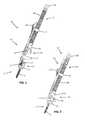
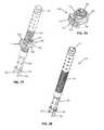
- FIG. 1is a perspective view of a rod reducer for urging a spinal rod to an anchor, according to a first example embodiment
- FIG. 2is a perspective of the example rod reducer of FIG. 1 with the rod in a fully reduced position within the anchor;
- FIG. 3is a side view of the example rod reducer of FIG. 1 ;
- FIG. 4is a backside view of the example rod reducer of FIG. 1 ;
- FIG. 5is a front side view of the example rod reducer of FIG. 1 ;
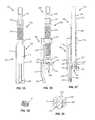
- FIG. 6is a perspective view of a coupling unit of the example rod reducer of FIG. 1 ;
- FIG. 7is a perspective view of a translating unit of the example rod reducer of FIG. 1 ;
- FIG. 8is another perspective view of the distal end of the translating unit of FIG. 7 ;
- FIG. 9is a perspective view of a translating coupler of the coupling unit of FIG. 6 ;
- FIGS. 10A-10Care side views of the example reducer of FIG. 1 depicting a sequence for reducing a rod, according to one example embodiment
- FIGS. 11-12are lateral and perspective views illustrating the final reduction position shown in 10 C in connection with a whole fixation construct fixing two adjacent vertebrae;
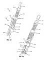
- FIG. 13is a perspective view of a rod reducer according to a second example embodiment
- FIG. 14is a different perspective view of the rod reducer of FIG. 13 ;
- FIG. 15is a back view of the example rod reducer of FIG. 13 ;
- FIG. 16is a side view of the example rod reducer of FIG. 13 ;
- FIG. 17is a cross-section view of the example rod reducer of FIG. 13 as viewed in FIG. 16 ;
- FIG. 18is a perspective view of an example embodiment of a locking cap for use with the reducers of FIGS. 1, 13, and 20 ;
- FIG. 19is a cross-section view of a the example locking cap of FIG. 18 preloaded onto the reducer of FIG. 13 , according to one example embodiment
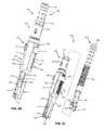
- FIG. 20is a perspective view of a rod reducer according to a third example embodiment
- FIG. 21is an exploded view illustrating a the coupling unit and translation unit of the example reducer of FIG. 20 ;
- FIG. 22is a side view of the example rod reducer of FIG. 20 ;
- FIG. 23is a front side view of the example rod reducer of FIG. 20 ;
- FIG. 24is a backside view of the example rod reducer of FIG. 20 ;
- FIG. 25is a cross-section view of the example rod reducer of FIG. 20 viewed in FIG. 22 ;
- FIG. 26is a cross-section view of the example rod reducer of FIG. 20 as viewed in FIG. 24 ;
- FIG. 27is a perspective view of a translating unit and translating coupler of the example rod reducer of FIG. 20 ;
- FIG. 28is a perspective view of the translating unit of FIG. 27 ;
- FIG. 29is a perspective view of the translating coupler of FIG. 27 ;
- FIGS. 30A-30Care side views of the example reducer of FIG. 20 depicting a sequence for reducing a rod, according to one example embodiment.
- the example reduction assembly, or reducer, embodiments described hereinare used during the installation of a fixation construct 10 onto the spine of a patient.
- the fixation construct 10includes anchor members 12 connected by a fixation rod 14 locked to each anchor 12 .
- An anchor 12is implanted in each vertebra to be fixed by the construct 10 .
- the anchor 12includes a bone anchor 18 and a housing 20 for capturing and locking a fixation rod 14 .
- the bone anchor 18may be a bone screw suitable for stable fixation to vertebral bone (e.g. pedicle or vertebral body), as shown.
- the bone anchor 18may also include other fixation devices (e.g. hooks, staples, clamps, etc. . . . ).
- the housing 20has a base that attaches with the bone anchor and a pair of upstanding arms that together form a rod channel 22 .
- the housingalso includes a mechanism 24 to lock the fixation rod 14 in position in the rod channel 22 .
- the mechanism 24may include a locking cap guide and advancement feature disposed on the interior face of each arm that interacts with a complementary feature on a locking cap 16 .
- the basemay be fixed to the anchor 18 or may be coupled such that the housing can rotate in one or more directions (e.g. polyaxial).
- the housingalso includes one or more instrument engagement features 26 for releasably coupling to one or more instruments during implantation.
- instrument engagement features 26for releasably coupling to one or more instruments during implantation.
- An anchorconfigured for use with the reducers described herein is shown and described in U.S. patent application Ser. No. 13/456,210, filed Apr. 25, 2012, the entire contents of which are incorporated herein by reference.
- the reducers described hereincan be engaged to one or more of the anchors 12 of the fixation construct 10 to facilitate alignment and advancement of the rod 14 into the rod channel 22 of each anchor.
- a reducer 100according to a first example embodiment is illustrated.
- the reducer 100is configured to couple to a single side or arm of anchor 12 (advantageously reducing bulk in the surgical corridor) and impart a downward force on the rod 14 .
- the downward force on the rodacts to draw the rod and anchor housing 20 together until the rod 14 fully seats in the rod channel 22 , as shown in FIG. 2 .
- a locking mechanismsuch as locking cap 16 (see FIG. 18 ), may then be at least partially engaged to capture the rod 14 in the housing 20 prior to decoupling the reducer 100 from the anchor 12 .
- the reducer 100includes a coupling unit 102 unit that connects to the anchor 12 and a translation unit 104 that translates relative to the coupling unit 102 to urge the rod 14 towards the anchor.
- the coupling unit 102includes a single anchor coupling arm 106 and a translation coupler 108 .
- the anchor coupling arm 106has a partially cylindrical profile with an inner face 110 and outer face 112 .
- a cavity 114 at the distal end of the coupling arm 106is dimensioned to snugly receive an arm of the anchor housing 20 therein.
- Included in the cavityis an engagement feature (not shown) that mates with the instrument engagement features 26 on the anchor to releasably fix the anchor housing 20 to the coupling arm 106 .
- the engagement featuremay be the same or similar to the engagement feature 216 of reducer 200 described below.
- the inner face 110has a lower elongated concave recess 116 with a central slot 118 extending deeper still towards the outer face 112 .
- a lower slot 120generally coinciding with the length of the recess 116 extends through the coupling arm 106 , opening near each edge of the outer face 112 and intersecting the central slot 118 .
- the inner face 110also includes an upper elongated concave recess 122 with a central slot 124 opening through the outer face.
- An upper slot 126generally coinciding with the length of the recess 122 extends through the coupling arm 106 , opening near each edge of the outer face 112 and intersecting the central slot 124 .
- the outer face 112includes a ridge track 128 , having a series of downward pointing ridges 130 . That is, the ridges 130 have an upper surface that slopes aggressively away and down from the outer face 112 .
- the lower surface of ridges 130may be perpendicular to the outer face, or preferably, may slope mildly also away and down from the outer face 112 .
- the translation coupler 108shown in FIG. 9 , includes an internally threaded ring 132 .
- a wing 134extends from the ring 132 through the central slot 124 and is pivotally connected to a switch 136 via pin 138 or other suitable mechanism.
- a stabilizing bar 140 situated in slot 126passes through an aperture 142 in the wing 134 to fix the translation coupler 108 to the coupling arm 106 while allowing the translation coupler to translate up and down along the slot 126 and upper recess 122 .
- a pawl 144 at the distal end of the switch 136engages the ridge track 128 to prevent upward or proximal translation without disengaging the pawl 144 .
- the switch 136is spring biased to the engaged pivot position.
- the application of downward forcecauses the pawl 144 to slide down the slope of the upper surface of each ridge 130 and automatically return to the engaged position when the pawl 144 passes the lower surface of the ridge 130 .
- the translation coupler 108can be advanced distally without manipulating the switch 136 but requires a user to manipulate the switch 136 to disengage the pawl 144 and allow proximal translation.
- the translation unit 104includes a threaded shaft 146 capped with a drive nut 148 at the proximal end and a foot 150 configured to engage and drive the rod 14 at the distal end.
- the threaded shaft 146engages the internal threading of the ring 132 to translate the translation unit 104 relative to the coupling unit 102 upon rotation of the shaft 146 .
- the drive nut 148can be engaged by a handle (not shown) to facilitate rotation.
- the foot 150includes a cylindrical body 152 that complements the lower recess 116 and that is coupled to the shaft 146 in such a way that the foot 150 and shaft 146 are fixed longitudinally but freely rotatable relative to each other.
- the distal end of the shaft 146can include flexible fingers having a ridge that is received in the internal groove of the cylindrical body 152 .
- a wing 154extends from the cylindrical body and is situated in the central slot 118 .
- a stabilizing bar 156 situated in slot 120passes through an aperture 158 in the wing 154 to stabilize the foot and eliminate any movement of the foot other than translation up and down along the slot 120 and lower recess 116 .
- a brim 160extends out and down from the portion of the cylindrical body 152 not in contact with the inner recess 116 .
- An inner cavity 162 enclosed by the brim 160is configured to receive a portion of the anchor housing 20 therein.
- the front of brim 160descends lower than the sides such that a rod recess 164 is formed between the coupling arm 102 and the brim front to help capture and guide the rod into the rod channel 22 .
- Passage 166extends through the translation unit 104 from the drive nut 148 to the foot 150 to receive locking cap 16 and a driver therethrough to engage the locking cap 16 to the housing 20 prior to removing the reducer 100 .
- the translation unit 104may further be configured to carry a preloaded locking cap, as illustrated below with respect to reducer 200 .
- Anchors 12are implanted in each of the vertebra to be fixed, including anchor 12 in vertebraV 1 which is the anchor to be reduced in this example, and the rod is inserted to the anchor housings.
- the rodrests above the housing 20 .
- the distal end of the coupling arm 102is advanced onto an arm of the anchor housing 20 until the engagement features on the coupling arm 102 engage with the engagement feature 26 of the housing 20 .
- the coupling arm 102is coupled to the housing with the foot 150 of the translation unit 104 spaced proximal to the housing 20 and the rod 14 .
- the translation coupler 108acts as quick-advance mechanism to advance the translation unit 104 without requiring the added effort and time required to threadingly advance the shaft 146 through the threaded ring 132 .
- the pawl 144engages each ridge 130 on the track 128 in turn to prevent unwanted proximal translation.
- the translation coupler 108 and translation unit 104can be advanced this way until the translation unit bottoms out on the slots 124 and/or 126 , the foot 150 reaches the rod 14 ( FIG. 10B ), or beyond that, the force required to further move the rod becomes too great.
- the threaded shaft 146is rotated to advance the threading through the threaded ring 132 until the rod is fully seated in the anchor housing 20 , as shown in FIG. 10C .
- FIGS. 11 and 12illustrate this final position shown in 10 C with the additional anchor 12 of fixation construct 10 implanted in adjacent vertebra V 2 . Though shown as a two level construct, additional anchors 12 can be implanted in additional vertebrae to extend the construct 10 over multiple levels.
- the construct 10may also be implanted bilaterally with additional anchors 12 and another rod 14 implanted on the contralateral side of the vertebrae V 1 and V 2 .
- the reducer 100may be used on any or all of the anchors 12 in the construct.
- a locking cap 16can be advanced through the passage 166 and engaged with the locking engagement feature 24 to capture and lock the rod 14 to the anchor 12 .
- the switch 136can then be manipulated to disengage the pawl 144 from the track 128 retract the translating unit 104 if desired, and the coupling arm 102 is disengaged from the housing 20 .
- Reducer 200is similar to reducer 100 and is also configured to couple to a single side or arm of anchor 12 .
- the reducer 200includes a coupling unit 202 that connects to the anchor 12 and a translation unit 204 that translates relative to the coupling unit 202 to urge the rod 14 towards the anchor.
- the coupling unit 202includes a single anchor coupling arm 206 .
- the anchor coupling arm 206has a partially cylindrical profile with an inner face 208 and an outer face 210 .
- a cavity 212 at the distal end of the coupling arm 206is dimensioned to snugly receive an arm of the anchor housing 20 therein.
- An engagement feature 214includes a flexible finger 216 formed in the coupling arm and having a distal ridge 218 that projects into the cavity 14 to engage the engagement features 26 of the housing 20 .
- the distal surface of the ridge 218is tapered to automatically deflect the finger 216 outward as the arm of housing 20 is advanced into cavity 212 , permitting the ridge 218 to pass the top of the housing until it engages the feature 26 .
- the inner face 208includes a central slot 220 and a slot 222 that extends through the coupling arm 206 opening near each edge of the outer face 210 and intersecting the central slot 220 .
- a fixed coupling body 224projects inward from the proximal end of the coupling arm 206 and encloses a threaded passage 226 .
- the translation unit 204includes a threaded shaft 228 capped with a drive nut 230 at the proximal end and a foot 232 configured to engage and drive the rod 14 at the distal end.
- the threaded shaft 228engages the internal threading of the passage 226 .
- the drive nut 230can be engaged by a handle (not shown) to facilitate rotation that translates the translation unit 204 relative to the coupling unit 202 .
- the foot 232includes a generally cylindrical body 234 that complements the inner face 208 and that is coupled to the shaft 228 in such a way that the foot 232 and shaft 228 are fixed translationally but freely rotatable relative to each other.
- a wing 236extends from the cylindrical body 234 and is situated in the central slot 220 .
- a stabilizing bar 238 situated in slot 222passes through an aperture in the wing 236 to stabilize the foot and eliminate any movement of the foot other than translation up and down.
- a brim 240extends out and down from the portion of the cylindrical body 152 not in contact with the inner face 208 .
- An inner cavity 242 enclosed by the brim 240is configured to receive a portion of the anchor housing 20 therein.
- the front of brim 240descends lower than the sides such that a rod recess 244 is formed between the coupling arm 202 and the brim front to help capture and guide the rod into the rod channel 22 .
- An opening 246 in the front of the foot 232provides a view into the foot to permit viewing of a preloaded locking cap 16 (not shown).
- the translation unit 204further includes a passage 248 extending from the drive nut 230 to the foot 232 in which a drive shaft 250 having a distal drive feature 252 is situated.
- a rim 254 above the drive featuremaintains the drive feature within the foot 232 .
- the drive shaftis permitted to freely translate a limited distance within the passage 248 such that the locking cap may be engaged and fully advanced into the anchor housing 20 .
- An expansion ring 256 situated in a groove just below the drive feature 252maintains the locking cap 16 on the drive feature 252 ( FIG. 19 ) until the locking cap 16 is engaged in the housing, after which the drive feature 252 may be removed from the locking cap by pulling up on the drive shaft.
- the reducer 200is used similarly to the reducer 100 but without the-quick advance translation.
- anchors 12are implanted in each of the vertebra to be fixed and the rod is inserted to the anchor housings.
- the distal end of the coupling arm 202is advanced onto an arm of the anchor housing 20 until the engagement features 216 on the coupling arm 202 engage with the engagement feature 26 of the housing 20 .
- the coupling arm 202is coupled to the housing with the foot 232 of the translation unit 204 spaced proximal to the housing 20 and the rod 14 .
- a handlemay be coupled to the drive nut 230 and the threaded shaft 228 rotated to advance the threading through the threaded passage 226 translating the foot 232 distally until the rod 14 is fully seated in the anchor housing 20 .
- additional anchorscan be implanted to extend the construct 10 over multiple levels and/or bi-laterally.
- a reducer 300according to a third example embodiment is illustrated.
- the reducer 300is configured to couple to an implanted anchor housing 20 and impart a downward force on the rod 14 .
- the downward force on the rodacts to draw the rod and housing 20 together until the rod 14 fully seats in the rod channel 22 .
- a locking mechanismsuch as locking cap 16 , may then be at least partially engaged to capture the rod 14 in the housing 20 prior to decoupling the reducer 100 from the anchor 12 .
- the reducer 300includes a coupling unit 302 unit that connects to the anchor 12 and a translation unit 304 that translates relative to the coupling unit 302 to urge the rod 14 towards the anchor.
- the coupling unit 302includes an outer sleeve 306 and a translation coupler 308 .
- the outer sleeve 306has a generally centralized and cylindrical body 310 .
- a connector mast 312extends proximally from the body 310 and a pair of anchor coupling arms 316 extend distally from the body.
- the connector mast 312is capped by a head 314 that is configured to engage with additional instruments if desired.
- the headis configured to mimic the proximal end of the minimally invasive guides described in U.S.
- the anchor coupling arms 316are separated by a channel 318 that aligns with the anchor rod channel 22 when the reducer 300 is coupled to the anchor 12 .
- a cavity 320 at the distal end of the coupling arms 316is dimensioned to snugly receive the arms of the anchor housing 20 therein.
- An engagement feature 322is included on each coupling arm.
- the engagement feature 322includes a flexible finger 324 formed in the coupling arm and having a distal ridge 326 that projects into the cavity 320 to engage the engagement features 26 of the housing 20 .
- the distal surface of the ridges 326are tapered to automatically deflect the finger 324 outward as the arms of housing 20 are advanced into cavity 320 , permitting the ridges 326 to pass the tops of the housing arms until they engages the anchor features 26 .
- the reducer 300can be positioned over the rod and quickly snapped onto and secured to the anchor with the simple application of downward pressure.
- an instrumentmay be advanced into the channel and manipulated to apply outward pressure to each of the fingers 324 .
- the body 310is split into four quadrants including a front wall 328 , a back wall 330 , and two sidewalls 332 .
- Four elongated side slots 334separate each wall from the next.
- An elongated front slot 336also runs through the middle of the front wall 328 .
- the back wall 330includes a ridge track 338 , having a series of downward pointing ridges 340 . That is, the ridges 340 have an upper surface that slopes aggressively away and down from the back wall 330 .
- the lower surface of ridges 340may be perpendicular to the outer face, or preferably, may slope mildly also away and down from the back wall 330 .
- the translation coupler 308shown in FIG. 29 , includes an internally threaded ring 342 surrounded by a front plate 344 and a back plate 346 .
- Bars 348couple the front plate 344 and back plate 346 together and engage cutouts in the outer surface of threaded ring 342 to longitudinally and rotationally fix the ring 342 in position relative to the front and back plates.
- the bars 348can slide along the ring 342 cutouts such that the front plate 344 can be moved towards the ring 342 causing the back plate 344 to move farther away from the ring 342 , and vice versa.
- the bars 348couple the front and back plates through the side slots 334 such that the translation coupler 308 is coupled to body 310 and can translate up and down along the body 310 with the front plate 344 moving along the front wall 328 and the back plate 346 moving along the back wall 330 .
- the inner surface of the back plate 346includes a row of ridges 350 that are complementary to the ridges 340 of ridge track 338 and thus, inhibit upward or proximal translation of the translation coupler 308 when the ridges 350 and 340 are engaged.
- the inner surface of the front plate 344includes a pair of cylindrical spring housings 352 situated centrally one on top of the other. The cylindrical spring housings 352 are dimensioned to pass through the front slot 336 .
- the springs 354 fitted in the housings 352engage the threaded ring 342 to bias the front plate 344 away from the front wall 328 and the back plate 346 into contact with the back wall 330 and hence the ridge track 338 .
- the application of downward forcecauses ridges 350 to slide down the sloped upper surfaces of each ridge 340 and automatically return to the engaged position when the ridge 350 passes the lower surface of the ridge 340 .
- the translation coupler 308can be advanced distally by the application of downward force, but requires a user to manipulate front plate 344 to disengage the back plate 346 from the back wall 330 and allow proximal translation.
- Other configurations for lockingly engaging the back plate 346 to the back wallare also contemplated.
- the side slots 334 adjacent the back wallcan have circular cutouts along the slot length.
- a pair of cylindrical barscan be used on each side to connect the front and back plates instead of the single flat bar 348 , the cylindrical bars passing through cylindrical cutouts in the threaded ring 342 , and connecting to the back plate 346 via enlarged cylindrical discs that are dimensioned to slide laterally into the circular cutouts but cannot pass from one cutout to the next along the slot 334 .
- the translation unit 304includes a shaft 356 capped with a drive nut 358 at the proximal end and a pusher member 360 ending in a pair of reduction arms 362 at the distal end.
- the reduction arms 362are situated between the coupling arms 316 and align with the channel 318 on each side.
- the distal ends of reduction arms 362are preferably concave in shape to contour to the rod.
- Protrusions 364 just above each reduction arm 360 on the pusher member 360slide along the channel 318 between the coupling arms 316 to prevent rotation of the pusher member 360 .
- the drive nut 148can be engaged by a handle (not shown) to facilitate rotation.
- the pusher member 360is coupled to the threaded shaft 356 in such a way that the pusher member and shaft are fixed longitudinally but freely rotatable relative to each other.
- the distal end of the threaded portionincludes flexible fingers 366 each having a ridge 370 that is received in an internal groove 368 of the pusher member 360 .
- a passage 372extends through the translation unit 104 from the drive nut 148 to reduction arms 360 to receive locking cap 16 and a driver therethrough to engage the locking cap 16 to the housing 20 prior to removing the reducer 300 .
- the translation unit 304may further be configured to carry a preloaded locking cap, for example, as described and illustrated with respect to reducer 200 .
- Anchors 12are implanted in each of the vertebra to be fixed, including anchor 12 in vertebraV 1 which is the anchor to be reduced in this example, and the rod is inserted to the anchor housings.
- the distal ends of the coupling arms 316are advanced over the rod such that the rod 14 is captured in the channel 318 and onto the anchor housing 20 until the engagement features 324 engage the features 26 on the housing.
- the usercan then direct force distally onto the translation unit 304 such that the translation coupler 308 translates distally along the body 310 (translating the translating unit 304 distally along with it).
- the translation coupler 308acts as quick-advance mechanism to advance the translation unit 304 without requiring the added effort and time required to threadingly advance the shaft 356 through the threaded ring 342 .
- the back plate ridges 350engage each ridge 340 on the track 338 in turn to prevent unwanted proximal translation.
- the translation coupler 308 and translation unit 304can be advanced this way until the translation unit bottoms out on the slots 334 , the reduction arms 360 reach the rod 14 ( FIG. 30B ), or beyond that, the force required to further move the rod becomes too great or a more controlled and precise reduction is desired.
- the threaded shaft 356is rotated to advance the threading through the threaded ring 342 until the rod is fully seated in the anchor housing 20 , as shown in FIG. 30C .
- additional anchors 12can be implanted in additional vertebrae to extend the construct 10 over multiple levels and/or bilaterally with additional anchors 12 and another rod 14 implanted on the contralateral side of the vertebrae.
- the reducer 300may be used on any or all of the anchors 12 in the construct.
- a locking cap 16can be engaged with the locking engagement feature 24 to capture and lock the rod 14 to the anchor 12 .
- the front plate 344can then be depressed to disengage the back plate from the track 338 to retract the translating unit 104 if desired, and the reducer 300 disengaged from the housing 20 .
Landscapes
- Health & Medical Sciences (AREA)
- Orthopedic Medicine & Surgery (AREA)
- Neurology (AREA)
- Life Sciences & Earth Sciences (AREA)
- Surgery (AREA)
- Heart & Thoracic Surgery (AREA)
- Engineering & Computer Science (AREA)
- Biomedical Technology (AREA)
- Nuclear Medicine, Radiotherapy & Molecular Imaging (AREA)
- Medical Informatics (AREA)
- Molecular Biology (AREA)
- Animal Behavior & Ethology (AREA)
- General Health & Medical Sciences (AREA)
- Public Health (AREA)
- Veterinary Medicine (AREA)
- Surgical Instruments (AREA)
Abstract
Description
Claims (13)
Priority Applications (5)
| Application Number | Priority Date | Filing Date | Title |
|---|---|---|---|
| US14/217,101US9486256B1 (en) | 2013-03-15 | 2014-03-17 | Rod reduction assemblies and related methods |
| US14/634,729US10136927B1 (en) | 2013-03-15 | 2015-02-28 | Rod reduction assemblies and related methods |
| US16/201,884US10898241B2 (en) | 2013-03-15 | 2018-11-27 | Rod reduction assemblies and related methods |
| US17/122,900US11660128B2 (en) | 2013-03-15 | 2020-12-15 | Rod reduction assemblies and related methods |
| US18/162,148US12232783B2 (en) | 2013-03-15 | 2023-01-31 | Rod reduction assemblies and related methods |
Applications Claiming Priority (2)
| Application Number | Priority Date | Filing Date | Title |
|---|---|---|---|
| US201361802046P | 2013-03-15 | 2013-03-15 | |
| US14/217,101US9486256B1 (en) | 2013-03-15 | 2014-03-17 | Rod reduction assemblies and related methods |
Related Child Applications (1)
| Application Number | Title | Priority Date | Filing Date |
|---|---|---|---|
| US14/634,729Continuation-In-PartUS10136927B1 (en) | 2013-03-15 | 2015-02-28 | Rod reduction assemblies and related methods |
Publications (1)
| Publication Number | Publication Date |
|---|---|
| US9486256B1true US9486256B1 (en) | 2016-11-08 |
Family
ID=57210921
Family Applications (1)
| Application Number | Title | Priority Date | Filing Date |
|---|---|---|---|
| US14/217,101Active2034-04-15US9486256B1 (en) | 2013-03-15 | 2014-03-17 | Rod reduction assemblies and related methods |
Country Status (1)
| Country | Link |
|---|---|
| US (1) | US9486256B1 (en) |
Cited By (16)
| Publication number | Priority date | Publication date | Assignee | Title |
|---|---|---|---|---|
| US20160183983A1 (en)* | 2014-12-09 | 2016-06-30 | John A. Heflin | Spine alignment system |
| US20170325856A1 (en)* | 2011-10-11 | 2017-11-16 | Globus Medical, Inc. | Rod reducing apparatus and associated methods |
| US20180036044A1 (en)* | 2016-08-05 | 2018-02-08 | Amendia, Inc. | Clip-on reducer |
| US20180070987A1 (en)* | 2016-09-12 | 2018-03-15 | Wiltrom Co., Ltd. | Spinal surgical instrument, method of guiding thereof and system for bone stabilization |
| US20180132911A1 (en)* | 2015-05-12 | 2018-05-17 | Shandong Weigao Orthopedic Device Company Ltd | Grasping end of frog-style forceps |
| US20190083149A1 (en)* | 2010-01-15 | 2019-03-21 | Pioneer Surgical Technology, Inc. | Low friction rod persuader |
| US20190125417A1 (en)* | 2016-04-11 | 2019-05-02 | Aesculap Ag | Instrument for guiding a rod into an implant receiving area |
| US10966762B2 (en) | 2017-12-15 | 2021-04-06 | Medos International Sarl | Unilateral implant holders and related methods |
| US20210282820A1 (en)* | 2018-06-13 | 2021-09-16 | Nuvasive, Inc. | Rod Reduction Assemblies and Related Methods |
| US11291482B2 (en) | 2019-03-21 | 2022-04-05 | Medos International Sarl | Rod reducers and related methods |
| US11291481B2 (en) | 2019-03-21 | 2022-04-05 | Medos International Sarl | Rod reducers and related methods |
| US11553947B2 (en) | 2019-07-16 | 2023-01-17 | Aesculap Implant Systems, Llc | Spinal deformity sequential persuader |
| US11730522B2 (en) | 2017-10-20 | 2023-08-22 | Spine Wave, Inc. | Threaded spinal rod reducer |
| USD1004774S1 (en) | 2019-03-21 | 2023-11-14 | Medos International Sarl | Kerrison rod reducer |
| WO2025076022A1 (en)* | 2023-10-03 | 2025-04-10 | Orthopediatrics Corp. | Rod reducer with cinch lock |
| US12318121B2 (en) | 2020-11-09 | 2025-06-03 | Medos International Sàrl | Biplanar forceps reducers and methods of use |
Citations (291)
| Publication number | Priority date | Publication date | Assignee | Title |
|---|---|---|---|---|
| US929067A (en)* | 1907-10-10 | 1909-07-27 | William J Williamson | Hose-coupling. |
| US4282217A (en) | 1979-12-28 | 1981-08-04 | Italfarmaco S.P.A. | Pharmaceutical compositions containing a corticosteroid substance |
| US4450899A (en) | 1980-10-27 | 1984-05-29 | Flakt Aktiebolag | Method of regulating an outdoor steam condensor and apparatus for performing said method |
| US4927425A (en) | 1988-12-21 | 1990-05-22 | Zimmer, Inc. | Surgical rod pusher instrument |
| US4955885A (en) | 1988-12-21 | 1990-09-11 | Zimmer, Inc. | Surgical slider instrument and method of using instrument |
| US5020519A (en) | 1990-12-07 | 1991-06-04 | Zimmer, Inc. | Sagittal approximator |
| FR2677242A1 (en) | 1991-06-05 | 1992-12-11 | Jeanson Jean Francois | Push-bar device for spinal support |
| US5217497A (en) | 1990-07-04 | 1993-06-08 | Mehdian Seyed M H | Apparatus for use in the treatment of spinal disorders |
| USD346217S (en) | 1992-07-13 | 1994-04-19 | Acromed Corporation | Combined hook holder and rod mover for spinal surgery |
| DE4238339A1 (en) | 1992-11-13 | 1994-05-19 | Peter Brehm | Fastening screw for spinal column support rod - has hollow slotted head with female thread to accommodate grub-screw to firmly clamp rod in place |
| US5360431A (en) | 1990-04-26 | 1994-11-01 | Cross Medical Products | Transpedicular screw system and method of use |
| US5496321A (en) | 1993-11-19 | 1996-03-05 | Cross Medical Products, Inc. | Rod anchor seat having a sliding interlocking rod connector |
| WO1996021396A1 (en) | 1995-01-12 | 1996-07-18 | Euros | Spinal fixator |
| US5616143A (en) | 1995-02-06 | 1997-04-01 | Schlapfer; Johannes F. | Surgical forceps |
| US5681319A (en) | 1995-03-01 | 1997-10-28 | Biedermann; Lutz | Locking tool |
| US5716356A (en) | 1994-07-18 | 1998-02-10 | Biedermann; Lutz | Anchoring member and adjustment tool therefor |
| US5720751A (en) | 1996-11-27 | 1998-02-24 | Jackson; Roger P. | Tools for use in seating spinal rods in open ended implants |
| US5782833A (en) | 1996-12-20 | 1998-07-21 | Haider; Thomas T. | Pedicle screw system for osteosynthesis |
| US5782831A (en) | 1996-11-06 | 1998-07-21 | Sdgi Holdings, Inc. | Method an device for spinal deformity reduction using a cable and a cable tensioning system |
| US5810878A (en) | 1997-02-12 | 1998-09-22 | Sdgi Holdings, Inc. | Rod introducer forceps |
| US5910141A (en) | 1997-02-12 | 1999-06-08 | Sdgi Holdings, Inc. | Rod introduction apparatus |
| US5941885A (en) | 1996-10-08 | 1999-08-24 | Jackson; Roger P. | Tools for use in installing osteosynthesis apparatus utilizing set screw with break-off head |
| US5944720A (en) | 1998-03-25 | 1999-08-31 | Lipton; Glenn E | Posterior spinal fixation system |
| US6004349A (en) | 1997-01-06 | 1999-12-21 | Jackson; Roger P. | Set screw for use with osteosynthesis apparatus |
| US6059786A (en) | 1998-10-22 | 2000-05-09 | Jackson; Roger P. | Set screw for medical implants |
| US6123707A (en) | 1999-01-13 | 2000-09-26 | Spinal Concepts, Inc. | Reduction instrument |
| US6139549A (en) | 1996-04-09 | 2000-10-31 | Waldemar Link (Gmbh & Co.) | Spinal fixing device |
| US6183472B1 (en) | 1998-04-09 | 2001-02-06 | Howmedica Gmbh | Pedicle screw and an assembly aid therefor |
| US6189422B1 (en) | 1998-07-17 | 2001-02-20 | Karl Storz Gmbh & Co. Kg | Screwdriver |
| US6224598B1 (en) | 2000-02-16 | 2001-05-01 | Roger P. Jackson | Bone screw threaded plug closure with central set screw |
| FR2801492A1 (en) | 1999-11-30 | 2001-06-01 | Jean Jacques Martin | Gliding joint device for spinal support to ensure vertebrae are correctly aligned and treatment of spinal conditions in which the vertebrae require support, has improved positioning mechanism using tightening wires |
| US6248107B1 (en) | 2000-03-15 | 2001-06-19 | Sdgi Holdings, Inc. | System for reducing the displacement of a vertebra |
| US6251111B1 (en) | 1999-10-20 | 2001-06-26 | Sdgi Holdings, Inc. | Jack for pulling a vertebral anchor |
| US6251112B1 (en) | 2000-04-18 | 2001-06-26 | Roger P. Jackson | Thin profile closure cap for open ended medical implant |
| US6258090B1 (en) | 2000-04-28 | 2001-07-10 | Roger P. Jackson | Closure for open ended medical implant and removal tool |
| US20020016595A1 (en) | 1999-05-05 | 2002-02-07 | Gary K. Michelson | Screws of cortical bone and method of manufacture thereof |
| US6379356B1 (en) | 2000-04-26 | 2002-04-30 | Roger P. Jackson | Closure for open ended medical implant |
| US20020072751A1 (en) | 2000-12-08 | 2002-06-13 | Jackson Roger P. | Closure plug for open-headed medical implant |
| US20020072750A1 (en) | 2000-12-08 | 2002-06-13 | Jackson Roger P. | Set screw for medical implant with gripping side slots |
| US20020095153A1 (en) | 2001-09-12 | 2002-07-18 | Jones Robert J. | Spinal rod translation instrument |
| US6440133B1 (en) | 2001-07-03 | 2002-08-27 | Sdgi Holdings, Inc. | Rod reducer instruments and methods |
| US6440132B1 (en) | 2000-05-24 | 2002-08-27 | Roger P. Jackson | Open head bone screw closure with threaded boss |
| US20020133159A1 (en) | 2000-12-08 | 2002-09-19 | Jackson Roger P. | Closure for open-headed medical implant |
| WO2002094114A1 (en) | 2001-05-21 | 2002-11-28 | Karl Storz Gmbh & Co. Kg | Manipulator for handling a pedicule screw |
| US20030023243A1 (en) | 2001-07-27 | 2003-01-30 | Biedermann Motech Gmbh | Bone screw and fastening tool for same |
| US20030028195A1 (en) | 2001-07-25 | 2003-02-06 | Stephane Bette | Ancillary for spinal osteosynthesis system and process for implanting a spinal osteosynthesis system using the said ancillary |
| US20030032957A1 (en) | 2001-08-13 | 2003-02-13 | Mckinley Laurence M. | Vertebral alignment and fixation assembly |
| US6554834B1 (en) | 1999-10-07 | 2003-04-29 | Stryker Spine | Slotted head pedicle screw assembly |
| US6575981B1 (en) | 1999-02-04 | 2003-06-10 | Sdgi Holdings, Inc. | Methods and instrumentation for vertebral interbody fusion |
| JP2003265492A (en) | 2002-03-19 | 2003-09-24 | Robert Reed Shokai Co Ltd | Operation tool for implant |
| US20030187445A1 (en) | 2000-04-04 | 2003-10-02 | Peter T. Keith | Devices and methods for annular repair of intervertebral discs |
| US20030199872A1 (en) | 2002-04-17 | 2003-10-23 | Stryker Spine | Rod persuader |
| US6648888B1 (en)* | 2002-09-06 | 2003-11-18 | Endius Incorporated | Surgical instrument for moving a vertebra |
| US20030225408A1 (en) | 2002-06-04 | 2003-12-04 | Howmedica Osteonics Corp. | Apparatus for securing a spinal rod system |
| US20030236529A1 (en) | 2002-06-24 | 2003-12-25 | Endius Incorporated | Surgical instrument for moving vertebrae |
| US20040039383A1 (en) | 2002-08-26 | 2004-02-26 | Jackson Roger P | Nested closure plug and set screw with break-off heads |
| US20040049196A1 (en) | 2002-09-06 | 2004-03-11 | Jackson Roger P. | Helical wound mechanically interlocking mating guide and advancement structure |
| US6740089B2 (en) | 2002-01-10 | 2004-05-25 | Thomas T. Haider | Orthopedic hook system |
| US6743231B1 (en) | 2000-10-02 | 2004-06-01 | Sulzer Spine-Tech Inc. | Temporary spinal fixation apparatuses and methods |
| US20040147936A1 (en) | 2003-01-28 | 2004-07-29 | Rosenberg William S. | Spinal rod approximator |
| US20040158247A1 (en) | 2003-02-07 | 2004-08-12 | Arthit Sitiso | Polyaxial pedicle screw system |
| US20040162560A1 (en) | 2003-02-19 | 2004-08-19 | Raynor Donald E. | Implant device including threaded locking mechanism |
| US20040167526A1 (en) | 2002-09-06 | 2004-08-26 | Roger P. Jackson | Closure for rod receiving orthopedic implant having left handed thread removal |
| US20040167523A1 (en) | 2000-12-08 | 2004-08-26 | Jackson Roger P. | Closure for rod receiving orthopedic implant having a pair of spaced apertures for removal |
| US20040167524A1 (en) | 2002-09-06 | 2004-08-26 | Jackson Roger P. | Anti-splay medical implant closure with central multi-surface insertion and removal aperture |
| US20040167525A1 (en) | 2002-09-06 | 2004-08-26 | Jackson Roger P. | Anti-splay medical implant closure with multi-stepped removal counterbore |
| US20040254576A1 (en) | 2003-06-16 | 2004-12-16 | Depuy Acromed, Inc. | Rod reduction nut and driver tool |
| US20040267275A1 (en) | 2003-06-26 | 2004-12-30 | Cournoyer John R. | Spinal implant holder and rod reduction systems and methods |
| US20050010220A1 (en) | 2003-04-24 | 2005-01-13 | Simon Casutt | Instrument system for pedicle screws |
| US20050038430A1 (en) | 2003-08-11 | 2005-02-17 | Mckinley Laurence M. | Low profile vertebral alignment and fixation assembly |
| US20050059969A1 (en) | 2003-09-17 | 2005-03-17 | Depuy Acromed, Inc. | Rod approximator |
| US6884244B1 (en) | 2000-06-06 | 2005-04-26 | Roger P. Jackson | Removable medical implant closure for open headed implants |
| US20050119667A1 (en) | 2003-12-02 | 2005-06-02 | Eurosurgical Sa | Clip-type surgical instrument for spinal implant |
| WO2005055843A1 (en) | 2003-12-02 | 2005-06-23 | Eurosurgical | Clipping-type surgical instrument for spinal implant |
| WO2005058141A2 (en) | 2003-12-17 | 2005-06-30 | Depuy Spine, Inc. | Instruments and methods for bone anchor engagement and spinal rod reduction |
| US20050149048A1 (en) | 2003-12-23 | 2005-07-07 | Eurosurgical Sa | Surgical instrument of the releaser type for a spinal implant |
| WO2005063135A1 (en) | 2003-12-23 | 2005-07-14 | Eurosurgical | Surgical instrument that can be unclipped and is used for a spinal implant |
| US20050171540A1 (en) | 2004-01-30 | 2005-08-04 | Roy Lim | Instruments and methods for minimally invasive spinal stabilization |
| US20050182410A1 (en) | 2002-09-06 | 2005-08-18 | Jackson Roger P. | Helical guide and advancement flange with radially loaded lip |
| US20050187549A1 (en) | 2000-06-06 | 2005-08-25 | Jackson Roger P. | Removable medical implant closure |
| US20050192579A1 (en) | 2004-02-27 | 2005-09-01 | Jackson Roger P. | Orthopedic implant rod reduction tool set and method |
| US20050192587A1 (en) | 2004-02-27 | 2005-09-01 | Lim Roy K. | Rod reducer |
| US20050228392A1 (en) | 2004-04-12 | 2005-10-13 | Keyer Thomas R | Rod persuader |
| US20050261687A1 (en) | 2004-04-20 | 2005-11-24 | Laszlo Garamszegi | Pedicle screw assembly |
| US20050261702A1 (en) | 2004-03-09 | 2005-11-24 | Showa Ika Kohgyo Co., Ltd. | Auxiliary instrument for fixing rod |
| US20060009775A1 (en) | 2004-07-06 | 2006-01-12 | Brian Dec | Spinal rod insertion instrument |
| US20060009773A1 (en) | 2002-09-06 | 2006-01-12 | Jackson Roger P | Helical interlocking mating guide and advancement structure |
| US20060025771A1 (en) | 2000-08-23 | 2006-02-02 | Jackson Roger P | Helical reverse angle guide and advancement structure with break-off extensions |
| US20060025769A1 (en) | 2004-07-30 | 2006-02-02 | Dick Jeffrey C | Surgical devices and methods for vertebral shifting utilizing spinal fixation systems |
| US20060025768A1 (en) | 2003-07-03 | 2006-02-02 | Andy Iott | Top loading spinal fixation device and instruments for loading and handling the same |
| US20060036260A1 (en) | 2004-08-06 | 2006-02-16 | Runco Thomas J | Instrument for guiding a rod into an implant in a spinal fixation system |
| US20060036254A1 (en) | 2004-08-10 | 2006-02-16 | Roy Lim | Reducing instrument for spinal surgery |
| US20060069391A1 (en) | 2004-02-27 | 2006-03-30 | Jackson Roger P | Spinal fixation tool attachment structure |
| US20060079909A1 (en) | 2003-12-17 | 2006-04-13 | Runco Thomas J | Instruments and methods for bone anchor engagement and spinal rod reduction |
| US20060083603A1 (en) | 2000-08-23 | 2006-04-20 | Jackson Roger P | Reverse angled threadform with anti-splay clearance |
| US20060089651A1 (en) | 2004-10-26 | 2006-04-27 | Trudeau Jeffrey L | Apparatus and method for anchoring a surgical rod |
| US20060095035A1 (en) | 2004-11-03 | 2006-05-04 | Jones Robert J | Instruments and methods for reduction of vertebral bodies |
| US20060111715A1 (en) | 2004-02-27 | 2006-05-25 | Jackson Roger P | Dynamic stabilization assemblies, tool set and method |
| US20060111730A1 (en) | 2004-11-23 | 2006-05-25 | Medical Innovators, Inc. | Deformity reduction instrument and method |
| US20060111713A1 (en) | 2004-11-23 | 2006-05-25 | Jackson Roger P | Spinal fixation tool set and method |
| US20060149235A1 (en) | 2004-12-20 | 2006-07-06 | Jackson Roger P | Medical implant fastener with nested set screw and method |
| US20060149238A1 (en) | 2005-01-04 | 2006-07-06 | Sherman Michael C | Systems and methods for spinal stabilization with flexible elements |
| US20060166534A1 (en) | 2005-01-26 | 2006-07-27 | Brumfield David L | Reducing instrument for spinal surgery |
| US20060184178A1 (en) | 2004-02-27 | 2006-08-17 | Jackson Roger P | Orthopedic implant rod reduction tool set and method |
| US20060247630A1 (en) | 2005-04-27 | 2006-11-02 | Andrew Iott | Percutaneous vertebral stabilization system |
| US20060253120A1 (en) | 2005-04-29 | 2006-11-09 | Sdgi Holdings, Inc. | Apparatus and method for positioning an implant during surgery |
| US20060264934A1 (en) | 2005-05-18 | 2006-11-23 | Medicinelodge, Inc. | System and method for orthopedic implant configuration |
| US20060271050A1 (en) | 2005-03-30 | 2006-11-30 | Gabriel Piza Vallespir | Instrumentation and methods for reducing spinal deformities |
| US20060276789A1 (en) | 2005-05-27 | 2006-12-07 | Jackson Roger P | Polyaxial bone screw with shank articulation pressure insert and method |
| US20060293690A1 (en) | 2005-05-23 | 2006-12-28 | Custom Spine, Inc. | Rod reducer |
| US20060293692A1 (en) | 2005-06-02 | 2006-12-28 | Whipple Dale E | Instruments and methods for manipulating a spinal fixation element |
| US20060293661A1 (en) | 2005-06-08 | 2006-12-28 | Rsb Spine Llc | Procedure for aligning and stabilizing bone elements |
| US20070032162A1 (en)* | 2004-11-23 | 2007-02-08 | Jackson Roger P | Spinal fixation tool set and method |
| US20070043378A1 (en) | 2005-07-21 | 2007-02-22 | Rakesh Kumar | Instrument for inserting, adjusting and removing a surgical implant |
| US20070093817A1 (en) | 2005-09-29 | 2007-04-26 | Michael Barrus | Spinal fixation system having locking and unlocking devices for use with a multi-planar, taper lock screw |
| US20070093849A1 (en) | 2005-09-29 | 2007-04-26 | Jones Scott A | Single action anti-torque rod reducer |
| US20070161998A1 (en) | 2005-10-28 | 2007-07-12 | Dale Whipple | Instruments and Methods For Manipulating A Spinal Rod |
| US20070162010A1 (en) | 2005-03-04 | 2007-07-12 | Chao Nam T | Instruments and methods for manipulating vertebra |
| US20070213714A1 (en) | 2006-02-07 | 2007-09-13 | Sdgi Holdings, Inc. | Surgical instruments and techniques for percutaneous placement of spinal stabilization elements |
| US20070213722A1 (en) | 2006-03-09 | 2007-09-13 | Jones Scott A | Dual action rod reducing and locking device and method |
| EP1839606A1 (en) | 2006-03-31 | 2007-10-03 | BIEDERMANN MOTECH GmbH | Locking assembly for securing a rod member in a receiver part for use in spinal or trauma surgery, bone anchoring device with such a locking assembly and tool therefor |
| US20070233072A1 (en) | 2006-03-01 | 2007-10-04 | Sdgi Holdings, Inc. | Modular fastener assemblies for spinal stabilization systems and methods |
| US20070255284A1 (en) | 2006-04-28 | 2007-11-01 | Sdgi Holdings, Inc. | Orthopedic implant apparatus |
| JP2007298123A (en) | 2006-05-01 | 2007-11-15 | Nippon Pillar Packing Co Ltd | Divided type mechanical seal |
| US20070270868A1 (en) | 2006-04-24 | 2007-11-22 | Sdgi Holdings, Inc. | Cam based reduction instrument |
| US20070270869A1 (en) | 2006-04-25 | 2007-11-22 | Young John S | Surgical instrumentation for rod reduction |
| US20070276379A1 (en) | 2005-02-09 | 2007-11-29 | Miller Keith E | Reducing instrument for spinal surgery |
| US20070282337A1 (en) | 2006-05-18 | 2007-12-06 | Laszlo Garamszegi | Rod reducer |
| US20070288002A1 (en) | 2006-05-30 | 2007-12-13 | Carls Thomas A | Locking device and method employing a posted member to control positioning of a stabilization member of a bone stabilization system |
| US20070299450A1 (en) | 2004-12-31 | 2007-12-27 | Ji-Hoon Her | Pedicle Screw and Device for Injecting Bone Cement into Bone |
| CN101103935A (en) | 2007-07-25 | 2008-01-16 | 朱大成 | Orthopedic vertebral body repositioning device |
| US20080015601A1 (en) | 2006-06-14 | 2008-01-17 | Michael Castro | Reduction device and method of use |
| US20080039848A1 (en) | 2002-09-06 | 2008-02-14 | Jackson Roger P | Anti-splay medical implant closure with multi-surface removal aperture |
| US20080045955A1 (en) | 2006-08-16 | 2008-02-21 | Berrevoets Gregory A | Spinal Rod Anchor Device and Method |
| US20080045950A1 (en) | 2006-08-17 | 2008-02-21 | Warsaw Orthopedic, Inc. | Reducing device |
| US20080045970A1 (en) | 2006-08-17 | 2008-02-21 | Sean Saidha | Push-off driver and method for inserting bone screws |
| US20080045953A1 (en) | 2006-07-14 | 2008-02-21 | Laszlo Garamszegi | Pedicle screw assembly with inclined surface seat |
| EP1891904A1 (en) | 2006-08-24 | 2008-02-27 | BIEDERMANN MOTECH GmbH | Bone anchoring device |
| US20080051781A1 (en) | 2006-08-04 | 2008-02-28 | Wyatt Drake Geist | Connecting rod for bone anchors having a bioresorbable tip |
| US20080051794A1 (en) | 2006-08-22 | 2008-02-28 | Brian Dec | Reduction sleeve |
| US20080091213A1 (en) | 2004-02-27 | 2008-04-17 | Jackson Roger P | Tool system for dynamic spinal implants |
| KR20080035999A (en) | 2007-02-06 | 2008-04-24 | 신세스 게엠바하 | Spinal rod insertion device |
| US20080119852A1 (en) | 2006-11-20 | 2008-05-22 | Dalton Brian E | Bone repair device and method |
| US20080154277A1 (en) | 2004-10-26 | 2008-06-26 | Scott Machalk | Tool apparatus for locking a spinal rod in an anchoring device therefor |
| US20080172062A1 (en) | 2007-01-12 | 2008-07-17 | Depuy Spine, Inc. | Bone anchor manipulation device |
| US20080177269A1 (en) | 2006-12-07 | 2008-07-24 | Seelig Matthew E | Apparatus and methods for reduction of vertebral bodies in a spine |
| US20080195155A1 (en) | 2007-02-12 | 2008-08-14 | Jeffrey Hoffman | Locking instrument for implantable fixation device |
| US20080221626A1 (en) | 2006-09-25 | 2008-09-11 | Stryker Spine | Force limiting persuader-reducer |
| US20080221583A1 (en) | 2007-01-18 | 2008-09-11 | Amir Ali Sharifi-Mehr | Polyaxial screwdriver for a pedicle screw system |
| US20080228233A1 (en) | 2007-02-12 | 2008-09-18 | Jeffrey Hoffman | Instrument for manipulating spinal implant system |
| US20080234678A1 (en) | 2007-03-20 | 2008-09-25 | Robert Gutierrez | Rod reducer |
| US20080234765A1 (en) | 2007-03-13 | 2008-09-25 | Depuy Spine, Inc. | Rod reduction methods and devices |
| US20080243190A1 (en) | 2007-03-29 | 2008-10-02 | Depuy Spine, Inc. | In-line rod reduction device and methods |
| US20080300638A1 (en) | 2006-11-20 | 2008-12-04 | Depuy Spine, Inc. | Break-off screw extensions |
| US20080319477A1 (en) | 2007-06-21 | 2008-12-25 | Justis Jeff R | Anchor extenders for minimally invasive surgical procedures |
| US20090018593A1 (en) | 2007-07-13 | 2009-01-15 | Michael Barrus | Rod reduction device and method of use |
| US7481813B1 (en) | 2004-11-19 | 2009-01-27 | Alphatec Spine, Inc. | Securing device and corresponding methods thereof for bone fixation systems |
| US20090030420A1 (en) | 2007-07-26 | 2009-01-29 | Depuy Spine, Inc. | Spinal rod reduction instruments and methods for use |
| US20090062858A1 (en) | 2007-08-31 | 2009-03-05 | Sara Dziedzic | Methods and instruments for approximating misaligned |
| US20090062859A1 (en) | 2007-08-31 | 2009-03-05 | Michael Mahoney | Method and system for securing a rod to a bone anchor with a connector |
| US20090062860A1 (en) | 2007-08-31 | 2009-03-05 | Frasier William J | Spinal fixation implants |
| FR2920663A1 (en) | 2007-09-10 | 2009-03-13 | Kiscomedica Sa | Spinal osteosynthesis system installation assisting instrument for connecting consecutive vertebrae, has rod mounted in translation in sleeve so that rod end penetrates in sleeve, and application unit applying forces between sleeve and rod |
| US20090088764A1 (en) | 2007-09-28 | 2009-04-02 | Depuy Spine, Inc. | Dual pivot instrument for reduction of a fixation element and method of use |
| US20090105712A1 (en) | 2007-10-23 | 2009-04-23 | Andrew Dauster | Rod persuader |
| US20090149887A1 (en) | 2005-09-23 | 2009-06-11 | Fridolin Schlaepfer | Bone support apparatus |
| EP2070485A1 (en) | 2007-12-13 | 2009-06-17 | Biedermann Motech GmbH | Anchoring device for anchoring a rod in bones or vertebrae |
| US20090157125A1 (en)* | 2007-02-14 | 2009-06-18 | Jeffrey Hoffman | Spinal Rod Reducer and Cap Insertion Apparatus |
| US20090163962A1 (en) | 2007-12-20 | 2009-06-25 | Aesculap Implant Systems, Inc. | Locking device introducer instrument |
| US20090228053A1 (en) | 2008-03-10 | 2009-09-10 | Eric Kolb | Derotation instrument with reduction functionality |
| US20090228055A1 (en) | 2004-09-24 | 2009-09-10 | Jackson Roger P | Spinal fixation tool set and method for rod reduction and fastener insertion |
| US20090228054A1 (en) | 2008-01-29 | 2009-09-10 | Jeffrey Hoffman | Rod Locking Instrument |
| US20090234395A1 (en) | 2006-08-16 | 2009-09-17 | Hoffman Jeffrey A | Insertion Instrument for a Spinal Fixation System |
| US20090240292A1 (en) | 2008-03-21 | 2009-09-24 | Butler Michael S | Spinal Rod Guide For A Vertebral Screw Spinal Rod Connector Assembly |
| US20090254125A1 (en) | 2008-04-03 | 2009-10-08 | Daniel Predick | Top Loading Polyaxial Spine Screw Assembly With One Step Lockup |
| CN201328875Y (en) | 2008-12-16 | 2009-10-21 | 刘锋卫 | Hypodermically buried thoracolumbar screw rod reduction and fixation nail |
| US20090281582A1 (en) | 2008-05-08 | 2009-11-12 | Raul Villa | Instrument for the reduction of a rod into position in a pedicle screw |
| US20090299414A1 (en) | 2003-04-09 | 2009-12-03 | Jackson Roger P | Polyaxial bone screw with uploaded threaded shank and method of assembly and use |
| US20090306721A1 (en) | 2008-06-06 | 2009-12-10 | X-Spine Systems, Inc. | Retraction tube for use with capless pedicle screw |
| US20100024487A1 (en) | 2008-07-31 | 2010-02-04 | Abbott Spine Inc. | Surgical Instrument With Integrated Reduction And Distraction Mechanisms |
| US20100036432A1 (en) | 2008-08-05 | 2010-02-11 | Abbott Spine Inc. | Twist off reduction screw |
| US20100036434A1 (en) | 2008-08-05 | 2010-02-11 | Abbott Spine Inc. | Rescue reduction bone anchor |
| FR2935093A1 (en) | 2008-08-20 | 2010-02-26 | Jean Pierre Huitema | Rod i.e. spinal rod, locking assembly for use in rod or pin placing instrument, has clip whose edge is rejoined by surface of zone, so as to create thrust effect on rod or pin for allowing distraction or contraction effect on implant |
| WO2010024787A1 (en) | 2008-08-26 | 2010-03-04 | Hays Saglik Urunleri Ic Ve Dis Ticaret Limited Sirketi | Long body polyaxial posterior cervical screw |
| US20100057126A1 (en) | 2008-09-04 | 2010-03-04 | Zimmer Spine, Inc. | Dynamic vertebral fastener |
| US20100063552A1 (en) | 2005-05-04 | 2010-03-11 | Spinefrontier, Inc | Spinal screw assembly and screw insertion tool |
| US20100121385A1 (en) | 2008-11-10 | 2010-05-13 | Spinal Elements, Inc. | Rod reducer instrument for spinal surgery |
| US20100121386A1 (en) | 2008-11-05 | 2010-05-13 | Warsaw Orthopedic, Inc. | Progressive Reduction Instrument for Reduction of a Vertebral Rod and Method of Use |
| US7717942B2 (en) | 2004-05-28 | 2010-05-18 | Aesculap Ag | Bone screw and osteosynthesis device |
| US20100137875A1 (en) | 2008-10-14 | 2010-06-03 | Marino James F | Insertion and reduction tool for pedicle screw assembly |
| CN101732086A (en) | 2009-11-14 | 2010-06-16 | 常州鼎健医疗器械有限公司 | Pedicle nail with shape correcting function |
| US20100160921A1 (en) | 2008-12-19 | 2010-06-24 | Arthrocare Corporation | Cancellous bone displacement system and methods of use |
| US20100179602A1 (en) | 2009-01-15 | 2010-07-15 | Aesculap Implant Systems, Inc. | Receiver body for spinal fixation system |
| US20100185248A1 (en) | 2009-01-22 | 2010-07-22 | David Barry | Rod Coercer |
| US20100198272A1 (en) | 2007-07-20 | 2010-08-05 | Thomas Keyer | Polyaxial bone fixation element |
| US20100228302A1 (en) | 2009-03-04 | 2010-09-09 | Aesculap Implant Systems, Inc. | Spinal rod manipulator instrument |
| US20100262198A1 (en) | 2009-03-26 | 2010-10-14 | Reto Braunschweiler | Instrument set for inserting a stabilization system into the spinal column of a body |
| US20100292742A1 (en) | 2009-05-13 | 2010-11-18 | Stad Shawn D | Torque Limited Instrument For Manipulating A Spinal Rod Relative to a Bone Anchor |
| US20100298838A1 (en) | 2009-05-19 | 2010-11-25 | Alphatec Spine, Inc. | Surgical screwdriver |
| US20100305625A1 (en) | 2009-05-27 | 2010-12-02 | Kyle Kuntz | Surgical instrument for fixing a clamp to a bone fixation device |
| US20100312279A1 (en) | 2006-08-23 | 2010-12-09 | Gephart Matthew P | Minimally Invasive Surgical System |
| CN201684006U (en) | 2010-03-24 | 2010-12-29 | 上海微创骨科医疗科技有限公司 | Spine reduction tool |
| US20110004222A1 (en) | 2009-04-07 | 2011-01-06 | Lutz Biedermann | Tool for Use with a Bone Anchor, in Particular for Spinal Surgery |
| US20110009910A1 (en) | 2004-11-10 | 2011-01-13 | Jackson Roger P | Polyaxial bone screw with helically wound capture connection |
| US20110034962A1 (en) | 2003-01-24 | 2011-02-10 | Dunbar Jr William L | Spinal Rod Approximator |
| US20110040328A1 (en) | 2009-08-11 | 2011-02-17 | Zimmer Spine Austin, Inc. | System and method for performing vertebral reduction using a sleeve |
| US20110040335A1 (en) | 2008-04-22 | 2011-02-17 | Synthes Usa, Llc | Bone fixation element with reduction tabs |
| US7922749B2 (en) | 2006-04-14 | 2011-04-12 | Warsaw Orthopedic, Inc. | Reducing device |
| US20110087298A1 (en) | 2008-06-11 | 2011-04-14 | K2M, Inc. | Rod reduction device |
| US7927334B2 (en) | 2006-04-11 | 2011-04-19 | Warsaw Orthopedic, Inc. | Multi-directional rod reducer instrument and method |
| US7927360B2 (en) | 2006-01-26 | 2011-04-19 | Warsaw Orthopedic, Inc. | Spinal anchor assemblies having extended receivers |
| RU2009136963A (en) | 2009-10-06 | 2011-04-20 | Владимир Дмитриевич Усиков (RU) | METHOD FOR RESTORING POSITION OF A DISPLACED VERBE IN SURGICAL TREATMENT OF SPONDYLOSIS |
| US20110093015A1 (en) | 2009-10-20 | 2011-04-21 | Ramsay Christopher L | Spinal implant with a flexible extension element |
| US20110118791A1 (en) | 2008-06-11 | 2011-05-19 | K2M, Inc. | Rod reduction device |
| US20110137358A1 (en) | 2009-12-07 | 2011-06-09 | Katherine Manninen | Derotation Apparatus For Treating Spinal Irregularities |
| US20110166606A1 (en) | 2008-09-12 | 2011-07-07 | Synthes Usa, Llc | Reduction tool |
| US20110166610A1 (en) | 2009-08-07 | 2011-07-07 | Moti Altarac | Systems and methods for stabilization of bone structures, including thorocolumbar stabilization systems and methods |
| US20110172714A1 (en) | 2008-06-27 | 2011-07-14 | K2M, Inc. | System and method for performing spinal surgery |
| US20110184469A1 (en) | 2010-01-28 | 2011-07-28 | Warsaw Orthopedic, Inc. | Set screw alignment tool |
| US20110186787A1 (en) | 2008-10-22 | 2011-08-04 | Ferro Corporation | Electrically Conductive Polymeric Compositions, Contacts, Assemblies and Methods |
| US20110202096A1 (en)* | 2010-02-12 | 2011-08-18 | John White | Spinal Rod and Screw Securing Apparatus and Method |
| US20110218583A1 (en) | 2010-03-05 | 2011-09-08 | Biomet Manufacturing Corp. | Assembly Tool for Modular Implants and Associated Method |
| RU2010108859A (en) | 2010-03-09 | 2011-09-20 | ГОУ ВПО Кубанский государственный медицинский университет Федерального агентства по здравоохранению и социальному развитию (RU) | METHOD FOR INTRAOPERATIVE REDUCTION OF A SLIPPING CALL |
| US20110257692A1 (en) | 2010-01-15 | 2011-10-20 | Sandstrom Jason P | Low Friction Rod Persuader |
| WO2011133160A1 (en) | 2010-04-23 | 2011-10-27 | Synthes Usa, Llc | Spinal surgery instrument sets and methods |
| US20110263945A1 (en) | 2010-04-23 | 2011-10-27 | Synthes Usa, Llc | Minimally invasive instrument set, devices and related methods |
| DE202011102890U1 (en) | 2011-05-25 | 2011-11-16 | Humantech Germany Gmbh | Instrument for introducing and repositioning a spinal rod in a posterior screw-rod implant |
| US20110282390A1 (en) | 2008-10-01 | 2011-11-17 | Sherwin Hua | Systems and methods for pedicle screw stabilization of spinal vertebrae |
| USD649243S1 (en) | 2011-05-05 | 2011-11-22 | Ebi, Llc | Pusher for a rod reduction device |
| CN202044328U (en) | 2011-03-22 | 2011-11-23 | 邱勇 | Spinal reduction device |
| US20110313470A1 (en) | 2010-06-18 | 2011-12-22 | Spine Wave, Inc. | Pedicle Screw Extension for Use in Percutaneous Spinal Fixation |
| US20110313464A1 (en) | 2010-06-18 | 2011-12-22 | Spine Wave, Inc. | Method for fixing a connecting rod to a thoracic spine |
| US20110319938A1 (en) | 2010-06-24 | 2011-12-29 | Warsaw Orthopedic, Inc. | Coplanar deformity correction system |
| US20120022594A1 (en) | 2010-07-26 | 2012-01-26 | Spinal USA LLC | Minimally invasive surgical tower access devices and related methods |
| CN202146354U (en) | 2011-05-30 | 2012-02-22 | 陈建庭 | Spondylolisthesis lift reset device and slippage vertebra lift reset device |
| US20120053643A1 (en) | 2010-09-01 | 2012-03-01 | Michael Harper | Rod Reducing Instrument and Methods of Use Thereof |
| US8128629B2 (en) | 2009-01-22 | 2012-03-06 | Ebi, Llc | Rod coercer |
| US20120078308A1 (en) | 2010-09-27 | 2012-03-29 | Sara Dziedzic | Rod reduction instrument and methods of rod reduction |
| US20120083853A1 (en) | 2010-10-01 | 2012-04-05 | K2M, Inc. | Devices, systems, and methods for performing spinal surgery |
| US20120100497A1 (en) | 2009-06-23 | 2012-04-26 | Sung Ho Joo | Burner using plasma |
| US20120123431A1 (en) | 2010-10-13 | 2012-05-17 | Daniel Rae Robinson | Driver for a surgical device |
| US20120123487A1 (en) | 2010-11-17 | 2012-05-17 | Alphatec Spine, Inc. | Spinal instruments with set screw loading and retention apparatus and methods of use |
| US20120143269A1 (en) | 2010-12-03 | 2012-06-07 | Zimmer Spine | Surgical instrument |
| EP2462889A1 (en) | 2010-12-13 | 2012-06-13 | Biedermann Technologies GmbH & Co. KG | Bone anchoring device |
| CN202342173U (en) | 2011-11-18 | 2012-07-25 | 北京纳通科技集团有限公司 | Vertebra orthopedic rod placing device |
| US20120191144A1 (en) | 2011-01-26 | 2012-07-26 | Warsaw Orthopedic, Inc | Instrument for reduction of a vertebral rod and method of use |
| US20120203288A1 (en) | 2009-10-05 | 2012-08-09 | Robert Lange | Spinal fixation system and screwdriver tool for use with the same |
| US20120203291A1 (en) | 2011-02-03 | 2012-08-09 | Alphatec Spine, Inc. | Spinal fixation rod adjustment system and method |
| US20120215266A1 (en) | 2011-02-22 | 2012-08-23 | K2M, Inc. | Single action anti-torque rod reducer |
| DE202012102895U1 (en) | 2012-07-31 | 2012-08-27 | Chih-Hsuan Wei | Clamping device for positioning a flexible connecting rod for minimally invasive surgery |
| WO2012127268A1 (en) | 2011-03-18 | 2012-09-27 | Scient'x | A fitting tool for a pedicular anchoring system |
| WO2012127267A1 (en) | 2011-03-18 | 2012-09-27 | Scient'x | A pedicular anchoring system |
| US20120271365A1 (en) | 2008-12-17 | 2012-10-25 | Synthese USA, LLC | Rod reducer apparatus for spinal corrective surgery |
| US20120277808A1 (en) | 2011-04-26 | 2012-11-01 | Warsaw Orthopedic, Inc. | Instrument and method for reducing elongate connecting elements |
| US20120283786A1 (en) | 2011-05-05 | 2012-11-08 | Warsaw Orthopedic, Inc. | Anchors extender assemblies and methods for using |
| DE102011103252A1 (en) | 2011-05-25 | 2012-11-29 | Human Tech Germany Gmbh | Instrument for insertion and repositioning of spinal rod in dorsal screw-rod implant to treat disease of patient, has module mechanism with spinal column rod insertion elements movably connected with rear handle of instrument by thread |
| US20120303062A1 (en) | 2011-05-27 | 2012-11-29 | Yann Amstutz | Minimally invasive spinal fixation system including vertebral alignment features |
| US20130018419A1 (en) | 2011-07-13 | 2013-01-17 | Warsaw Orthopedic, Inc. | Spinal rod system and method |
| US20130030445A1 (en) | 2011-07-29 | 2013-01-31 | Aesculap Inplant Systems, LLC | Surgical instrumentation for spinal surgery |
| US20130035729A1 (en) | 2011-08-02 | 2013-02-07 | Blackstone Medical, Inc. | Bayonet counter-torque wrench |
| US20130046345A1 (en) | 2010-08-20 | 2013-02-21 | K2M, Inc. | Spinal fixation system |
| US8388659B1 (en) | 2008-10-17 | 2013-03-05 | Theken Spine, Llc | Spondylolisthesis screw and instrument for implantation |
| US20130066385A1 (en) | 2011-09-14 | 2013-03-14 | Warsaw Orthopedic, Inc. | Connecting element reduction instrument and methods for using same |
| US20130079827A1 (en) | 2011-09-27 | 2013-03-28 | Douglas Wayne Neary | Spinal rod persuader |
| EP2574297A1 (en) | 2011-09-30 | 2013-04-03 | Biedermann Technologies GmbH & Co. KG | Bone anchoring device and tool cooperating with such a bone anchoring device |
| US20130090697A1 (en) | 2011-10-11 | 2013-04-11 | Milan George | Rod-Reducing Apparatus and Associated Methods |
| US20130110124A1 (en) | 2011-10-31 | 2013-05-02 | Joeseph Gleason | Pedicle screw extension system |
| US20130110184A1 (en) | 2011-10-26 | 2013-05-02 | Alphatec Spine, Inc. | Systems for vertebral adjustments and rod reduction |
| FR2985166A1 (en) | 2012-01-02 | 2013-07-05 | Iceram | PUSH-ROD INSTRUMENT USED DURING SPINAL OPERATION |
| US20130184763A1 (en) | 2012-01-16 | 2013-07-18 | K2M, Inc. | Rod reducer, compressor, distractor system |
| US20130190822A1 (en) | 2012-01-20 | 2013-07-25 | Warsaw Orthopedic, Inc. | Soinal implant system and method |
| WO2013112689A2 (en) | 2012-01-25 | 2013-08-01 | Spinal Usa, Inc. | Minimally invasive devices and methods for delivering fixation devices and implants into a spine |
| US20130245692A1 (en) | 2012-03-19 | 2013-09-19 | Kyle Hayes | Spondylolisthesis reduction system |
| US20130253598A1 (en) | 2004-02-27 | 2013-09-26 | Roger P. Jackson | Orthopedic implant rod reduction tool set and method |
| WO2013150232A1 (en) | 2012-04-02 | 2013-10-10 | Safe Orthopaedics | Spinal osteosynthesis instrument kit |
| WO2013187928A1 (en) | 2012-06-14 | 2013-12-19 | Spine Wave, Inc. | Pedicle screw extension for use in percutaneous spinal fixation |
| US20130345759A1 (en) | 2012-06-26 | 2013-12-26 | K2M, Inc. | Spinal rod locking holder |
| WO2014013203A1 (en) | 2012-07-19 | 2014-01-23 | Safe Orthopaedics | Device for guiding a surgical instrument into position on a bone-anchor element including a means for realigning a link rod with the anchor element, and related system of surgical instruments |
| US20140039567A1 (en) | 2012-08-01 | 2014-02-06 | Aesculap Ag | Surgical apparatus |
| US20140058464A1 (en) | 2012-08-23 | 2014-02-27 | Synthes Usa, Llc | Bi-planar persuader |
| US20140074105A1 (en) | 2012-09-12 | 2014-03-13 | Warsaw Orthopedic, Inc. | Spinal implant system and method |
| US20140074106A1 (en) | 2012-09-12 | 2014-03-13 | Gs Medical Co., Ltd. | Working tower, rod inserter, rod reducer, and compression-distraction tool for minimally invasive surgery system |
| KR20140035296A (en) | 2013-12-13 | 2014-03-21 | 주식회사 지에스메디칼 | Rod reducer for minimally invasive surgery system |
| US20140100613A1 (en) | 2005-04-27 | 2014-04-10 | Globus Medical, Inc | Percutaneous Vertebral Stabilization System |
| EP2719347A1 (en) | 2012-10-09 | 2014-04-16 | Biedermann Technologies GmbH & Co. KG | Instrument for assembling a polyaxial bone anchor |
| US20140148865A1 (en) | 2012-11-29 | 2014-05-29 | Warsaw Orthopedic, Inc. | Spinal implant system and method |
| US20140163625A1 (en) | 2012-08-03 | 2014-06-12 | Alphatec Spine, Inc. | Instrument and method for reducing and securing spinal rods |
| US8777953B1 (en) | 2010-10-06 | 2014-07-15 | Greatbatch Ltd. | Rocker mechanism |
| US20140214084A1 (en) | 2013-01-28 | 2014-07-31 | Roger P. Jackson | Polyaxial bone anchor with receiver with spheric edge for friction fit |
| US20140214097A1 (en) | 2013-01-28 | 2014-07-31 | Roger P. Jackson | Dual medical implant closure drive system |
| US8828006B2 (en) | 2010-02-17 | 2014-09-09 | Blackstone Medical, Inc. | Anti-splay apparatus |
| US8900248B2 (en) | 2008-06-13 | 2014-12-02 | The University Of Toledo | Insertion assembly for minimally invasive spinal surgery |
- 2014
- 2014-03-17USUS14/217,101patent/US9486256B1/enactiveActive
Patent Citations (402)
| Publication number | Priority date | Publication date | Assignee | Title |
|---|---|---|---|---|
| US929067A (en)* | 1907-10-10 | 1909-07-27 | William J Williamson | Hose-coupling. |
| US4282217A (en) | 1979-12-28 | 1981-08-04 | Italfarmaco S.P.A. | Pharmaceutical compositions containing a corticosteroid substance |
| US4450899A (en) | 1980-10-27 | 1984-05-29 | Flakt Aktiebolag | Method of regulating an outdoor steam condensor and apparatus for performing said method |
| US4927425A (en) | 1988-12-21 | 1990-05-22 | Zimmer, Inc. | Surgical rod pusher instrument |
| US4955885A (en) | 1988-12-21 | 1990-09-11 | Zimmer, Inc. | Surgical slider instrument and method of using instrument |
| US5360431A (en) | 1990-04-26 | 1994-11-01 | Cross Medical Products | Transpedicular screw system and method of use |
| US5624442A (en) | 1990-04-26 | 1997-04-29 | Cross Medical Products, Inc. | Transverse link for use with a spinal implant system |
| US5217497A (en) | 1990-07-04 | 1993-06-08 | Mehdian Seyed M H | Apparatus for use in the treatment of spinal disorders |
| US5020519A (en) | 1990-12-07 | 1991-06-04 | Zimmer, Inc. | Sagittal approximator |
| FR2677242A1 (en) | 1991-06-05 | 1992-12-11 | Jeanson Jean Francois | Push-bar device for spinal support |
| USD346217S (en) | 1992-07-13 | 1994-04-19 | Acromed Corporation | Combined hook holder and rod mover for spinal surgery |
| DE4238339A1 (en) | 1992-11-13 | 1994-05-19 | Peter Brehm | Fastening screw for spinal column support rod - has hollow slotted head with female thread to accommodate grub-screw to firmly clamp rod in place |
| US5496321A (en) | 1993-11-19 | 1996-03-05 | Cross Medical Products, Inc. | Rod anchor seat having a sliding interlocking rod connector |
| US5716356A (en) | 1994-07-18 | 1998-02-10 | Biedermann; Lutz | Anchoring member and adjustment tool therefor |
| WO1996021396A1 (en) | 1995-01-12 | 1996-07-18 | Euros | Spinal fixator |
| US5616143A (en) | 1995-02-06 | 1997-04-01 | Schlapfer; Johannes F. | Surgical forceps |
| US5681319A (en) | 1995-03-01 | 1997-10-28 | Biedermann; Lutz | Locking tool |
| US6139549A (en) | 1996-04-09 | 2000-10-31 | Waldemar Link (Gmbh & Co.) | Spinal fixing device |
| US5941885A (en) | 1996-10-08 | 1999-08-24 | Jackson; Roger P. | Tools for use in installing osteosynthesis apparatus utilizing set screw with break-off head |
| US5782831A (en) | 1996-11-06 | 1998-07-21 | Sdgi Holdings, Inc. | Method an device for spinal deformity reduction using a cable and a cable tensioning system |
| US5720751A (en) | 1996-11-27 | 1998-02-24 | Jackson; Roger P. | Tools for use in seating spinal rods in open ended implants |
| US5782833A (en) | 1996-12-20 | 1998-07-21 | Haider; Thomas T. | Pedicle screw system for osteosynthesis |
| US6004349A (en) | 1997-01-06 | 1999-12-21 | Jackson; Roger P. | Set screw for use with osteosynthesis apparatus |
| US5810878A (en) | 1997-02-12 | 1998-09-22 | Sdgi Holdings, Inc. | Rod introducer forceps |
| US5910141A (en) | 1997-02-12 | 1999-06-08 | Sdgi Holdings, Inc. | Rod introduction apparatus |
| US5944720A (en) | 1998-03-25 | 1999-08-31 | Lipton; Glenn E | Posterior spinal fixation system |
| US6183472B1 (en) | 1998-04-09 | 2001-02-06 | Howmedica Gmbh | Pedicle screw and an assembly aid therefor |
| US6189422B1 (en) | 1998-07-17 | 2001-02-20 | Karl Storz Gmbh & Co. Kg | Screwdriver |
| US6059786A (en) | 1998-10-22 | 2000-05-09 | Jackson; Roger P. | Set screw for medical implants |
| US6123707A (en) | 1999-01-13 | 2000-09-26 | Spinal Concepts, Inc. | Reduction instrument |
| US6575981B1 (en) | 1999-02-04 | 2003-06-10 | Sdgi Holdings, Inc. | Methods and instrumentation for vertebral interbody fusion |
| US20020016595A1 (en) | 1999-05-05 | 2002-02-07 | Gary K. Michelson | Screws of cortical bone and method of manufacture thereof |
| US6554834B1 (en) | 1999-10-07 | 2003-04-29 | Stryker Spine | Slotted head pedicle screw assembly |
| US6251111B1 (en) | 1999-10-20 | 2001-06-26 | Sdgi Holdings, Inc. | Jack for pulling a vertebral anchor |
| FR2801492A1 (en) | 1999-11-30 | 2001-06-01 | Jean Jacques Martin | Gliding joint device for spinal support to ensure vertebrae are correctly aligned and treatment of spinal conditions in which the vertebrae require support, has improved positioning mechanism using tightening wires |
| US6224598B1 (en) | 2000-02-16 | 2001-05-01 | Roger P. Jackson | Bone screw threaded plug closure with central set screw |
| US6248107B1 (en) | 2000-03-15 | 2001-06-19 | Sdgi Holdings, Inc. | System for reducing the displacement of a vertebra |
| US20030187445A1 (en) | 2000-04-04 | 2003-10-02 | Peter T. Keith | Devices and methods for annular repair of intervertebral discs |
| US6251112B1 (en) | 2000-04-18 | 2001-06-26 | Roger P. Jackson | Thin profile closure cap for open ended medical implant |
| US6379356B1 (en) | 2000-04-26 | 2002-04-30 | Roger P. Jackson | Closure for open ended medical implant |
| US6258090B1 (en) | 2000-04-28 | 2001-07-10 | Roger P. Jackson | Closure for open ended medical implant and removal tool |
| US6440132B1 (en) | 2000-05-24 | 2002-08-27 | Roger P. Jackson | Open head bone screw closure with threaded boss |
| US20050187549A1 (en) | 2000-06-06 | 2005-08-25 | Jackson Roger P. | Removable medical implant closure |
| US6884244B1 (en) | 2000-06-06 | 2005-04-26 | Roger P. Jackson | Removable medical implant closure for open headed implants |
| US20060083603A1 (en) | 2000-08-23 | 2006-04-20 | Jackson Roger P | Reverse angled threadform with anti-splay clearance |
| US20060025771A1 (en) | 2000-08-23 | 2006-02-02 | Jackson Roger P | Helical reverse angle guide and advancement structure with break-off extensions |
| US6743231B1 (en) | 2000-10-02 | 2004-06-01 | Sulzer Spine-Tech Inc. | Temporary spinal fixation apparatuses and methods |
| US20020133159A1 (en) | 2000-12-08 | 2002-09-19 | Jackson Roger P. | Closure for open-headed medical implant |
| US20040167523A1 (en) | 2000-12-08 | 2004-08-26 | Jackson Roger P. | Closure for rod receiving orthopedic implant having a pair of spaced apertures for removal |
| US20020072750A1 (en) | 2000-12-08 | 2002-06-13 | Jackson Roger P. | Set screw for medical implant with gripping side slots |
| US20020072751A1 (en) | 2000-12-08 | 2002-06-13 | Jackson Roger P. | Closure plug for open-headed medical implant |
| WO2002094114A1 (en) | 2001-05-21 | 2002-11-28 | Karl Storz Gmbh & Co. Kg | Manipulator for handling a pedicule screw |
| US6440133B1 (en) | 2001-07-03 | 2002-08-27 | Sdgi Holdings, Inc. | Rod reducer instruments and methods |
| US20030028195A1 (en) | 2001-07-25 | 2003-02-06 | Stephane Bette | Ancillary for spinal osteosynthesis system and process for implanting a spinal osteosynthesis system using the said ancillary |
| US6726692B2 (en) | 2001-07-25 | 2004-04-27 | Spinevision | Ancillary for spinal osteosynthesis system and process for implanting a spinal osteosynthesis system using the said ancillary |
| US20030023243A1 (en) | 2001-07-27 | 2003-01-30 | Biedermann Motech Gmbh | Bone screw and fastening tool for same |
| US20030032957A1 (en) | 2001-08-13 | 2003-02-13 | Mckinley Laurence M. | Vertebral alignment and fixation assembly |
| US6520963B1 (en) | 2001-08-13 | 2003-02-18 | Mckinley Lawrence M. | Vertebral alignment and fixation assembly |
| US20020095153A1 (en) | 2001-09-12 | 2002-07-18 | Jones Robert J. | Spinal rod translation instrument |
| US6740089B2 (en) | 2002-01-10 | 2004-05-25 | Thomas T. Haider | Orthopedic hook system |
| JP2003265492A (en) | 2002-03-19 | 2003-09-24 | Robert Reed Shokai Co Ltd | Operation tool for implant |
| US20030199872A1 (en) | 2002-04-17 | 2003-10-23 | Stryker Spine | Rod persuader |
| US6660006B2 (en) | 2002-04-17 | 2003-12-09 | Stryker Spine | Rod persuader |
| US20030225408A1 (en) | 2002-06-04 | 2003-12-04 | Howmedica Osteonics Corp. | Apparatus for securing a spinal rod system |
| US7278995B2 (en)* | 2002-06-04 | 2007-10-09 | Howmedica Osteonics Corp. | Apparatus for securing a spinal rod system |
| US20030236529A1 (en) | 2002-06-24 | 2003-12-25 | Endius Incorporated | Surgical instrument for moving vertebrae |
| US20040039383A1 (en) | 2002-08-26 | 2004-02-26 | Jackson Roger P | Nested closure plug and set screw with break-off heads |
| US20040167526A1 (en) | 2002-09-06 | 2004-08-26 | Roger P. Jackson | Closure for rod receiving orthopedic implant having left handed thread removal |
| US20040167524A1 (en) | 2002-09-06 | 2004-08-26 | Jackson Roger P. | Anti-splay medical implant closure with central multi-surface insertion and removal aperture |
| US20040167525A1 (en) | 2002-09-06 | 2004-08-26 | Jackson Roger P. | Anti-splay medical implant closure with multi-stepped removal counterbore |
| US20050182410A1 (en) | 2002-09-06 | 2005-08-18 | Jackson Roger P. | Helical guide and advancement flange with radially loaded lip |
| US20060009773A1 (en) | 2002-09-06 | 2006-01-12 | Jackson Roger P | Helical interlocking mating guide and advancement structure |
| US20080039848A1 (en) | 2002-09-06 | 2008-02-14 | Jackson Roger P | Anti-splay medical implant closure with multi-surface removal aperture |
| US20040049196A1 (en) | 2002-09-06 | 2004-03-11 | Jackson Roger P. | Helical wound mechanically interlocking mating guide and advancement structure |
| US6648888B1 (en)* | 2002-09-06 | 2003-11-18 | Endius Incorporated | Surgical instrument for moving a vertebra |
| US7985242B2 (en) | 2002-10-30 | 2011-07-26 | Zimmer Spine, Inc. | Instruments and methods for reduction of vertebral bodies |
| US20080009864A1 (en) | 2002-10-30 | 2008-01-10 | Charlie Forton | Instruments and methods for reduction of vertebral bodies |
| US20110034962A1 (en) | 2003-01-24 | 2011-02-10 | Dunbar Jr William L | Spinal Rod Approximator |
| US7988698B2 (en) | 2003-01-28 | 2011-08-02 | Depuy Spine, Inc. | Spinal rod approximator |
| US20040147936A1 (en) | 2003-01-28 | 2004-07-29 | Rosenberg William S. | Spinal rod approximator |
| US20040158247A1 (en) | 2003-02-07 | 2004-08-12 | Arthit Sitiso | Polyaxial pedicle screw system |
| US20040162560A1 (en) | 2003-02-19 | 2004-08-19 | Raynor Donald E. | Implant device including threaded locking mechanism |
| US20090299414A1 (en) | 2003-04-09 | 2009-12-03 | Jackson Roger P | Polyaxial bone screw with uploaded threaded shank and method of assembly and use |
| US20050010220A1 (en) | 2003-04-24 | 2005-01-13 | Simon Casutt | Instrument system for pedicle screws |
| US7156849B2 (en) | 2003-06-16 | 2007-01-02 | Depuy Spine, Inc. | Rod reduction nut and driver tool |
| US20040254576A1 (en) | 2003-06-16 | 2004-12-16 | Depuy Acromed, Inc. | Rod reduction nut and driver tool |
| US20040267275A1 (en) | 2003-06-26 | 2004-12-30 | Cournoyer John R. | Spinal implant holder and rod reduction systems and methods |
| US20060025768A1 (en) | 2003-07-03 | 2006-02-02 | Andy Iott | Top loading spinal fixation device and instruments for loading and handling the same |
| US20050038430A1 (en) | 2003-08-11 | 2005-02-17 | Mckinley Laurence M. | Low profile vertebral alignment and fixation assembly |
| US6981973B2 (en) | 2003-08-11 | 2006-01-03 | Mckinley Laurence M | Low profile vertebral alignment and fixation assembly |
| US20050059969A1 (en) | 2003-09-17 | 2005-03-17 | Depuy Acromed, Inc. | Rod approximator |
| US20050119667A1 (en) | 2003-12-02 | 2005-06-02 | Eurosurgical Sa | Clip-type surgical instrument for spinal implant |
| WO2005055843A1 (en) | 2003-12-02 | 2005-06-23 | Eurosurgical | Clipping-type surgical instrument for spinal implant |
| US20060079909A1 (en) | 2003-12-17 | 2006-04-13 | Runco Thomas J | Instruments and methods for bone anchor engagement and spinal rod reduction |
| WO2005058141A2 (en) | 2003-12-17 | 2005-06-30 | Depuy Spine, Inc. | Instruments and methods for bone anchor engagement and spinal rod reduction |
| US7824413B2 (en) | 2003-12-17 | 2010-11-02 | Depuy Spine, Inc. | Instruments and methods for bone anchor engagement and spinal rod reduction |
| US20050149048A1 (en) | 2003-12-23 | 2005-07-07 | Eurosurgical Sa | Surgical instrument of the releaser type for a spinal implant |
| WO2005063135A1 (en) | 2003-12-23 | 2005-07-14 | Eurosurgical | Surgical instrument that can be unclipped and is used for a spinal implant |
| US20050171540A1 (en) | 2004-01-30 | 2005-08-04 | Roy Lim | Instruments and methods for minimally invasive spinal stabilization |
| US7597694B2 (en) | 2004-01-30 | 2009-10-06 | Warsaw Orthopedic, Inc. | Instruments and methods for minimally invasive spinal stabilization |
| US7862587B2 (en) | 2004-02-27 | 2011-01-04 | Jackson Roger P | Dynamic stabilization assemblies, tool set and method |
| US20140031872A1 (en) | 2004-02-27 | 2014-01-30 | Roger P. Jackson | Spinal fixation tool set and method |
| US20060111715A1 (en) | 2004-02-27 | 2006-05-25 | Jackson Roger P | Dynamic stabilization assemblies, tool set and method |
| US7470279B2 (en) | 2004-02-27 | 2008-12-30 | Jackson Roger P | Orthopedic implant rod reduction tool set and method |
| US20080091213A1 (en) | 2004-02-27 | 2008-04-17 | Jackson Roger P | Tool system for dynamic spinal implants |
| US20090228056A1 (en) | 2004-02-27 | 2009-09-10 | Jackson Roger P | Orthopedic implant rod reduction tool set and method |
| US7611517B2 (en) | 2004-02-27 | 2009-11-03 | Warsaw Orthopedic, Inc. | Rod reducer |
| US9050139B2 (en) | 2004-02-27 | 2015-06-09 | Roger P. Jackson | Orthopedic implant rod reduction tool set and method |
| US20060184178A1 (en) | 2004-02-27 | 2006-08-17 | Jackson Roger P | Orthopedic implant rod reduction tool set and method |
| US20150142060A1 (en) | 2004-02-27 | 2015-05-21 | Roger P. Jackson | Spinal fixation tool attachment structure |
| US20050192587A1 (en) | 2004-02-27 | 2005-09-01 | Lim Roy K. | Rod reducer |
| US20130304130A1 (en) | 2004-02-27 | 2013-11-14 | Roger P. Jackson | Tool system for dynamic spinal implants |
| US20130253598A1 (en) | 2004-02-27 | 2013-09-26 | Roger P. Jackson | Orthopedic implant rod reduction tool set and method |
| US8292892B2 (en) | 2004-02-27 | 2012-10-23 | Jackson Roger P | Orthopedic implant rod reduction tool set and method |
| US8066739B2 (en) | 2004-02-27 | 2011-11-29 | Jackson Roger P | Tool system for dynamic spinal implants |
| US20050192579A1 (en) | 2004-02-27 | 2005-09-01 | Jackson Roger P. | Orthopedic implant rod reduction tool set and method |
| US20060069391A1 (en) | 2004-02-27 | 2006-03-30 | Jackson Roger P | Spinal fixation tool attachment structure |
| US7909835B2 (en) | 2004-03-09 | 2011-03-22 | Showa Ika Kohgyo Co., Ltd. | Auxiliary instrument for fixing rod |
| US20050261702A1 (en) | 2004-03-09 | 2005-11-24 | Showa Ika Kohgyo Co., Ltd. | Auxiliary instrument for fixing rod |
| US7491207B2 (en) | 2004-04-12 | 2009-02-17 | Synthes Usa, Llc | Rod persuader |
| US20050228392A1 (en) | 2004-04-12 | 2005-10-13 | Keyer Thomas R | Rod persuader |
| US7678139B2 (en) | 2004-04-20 | 2010-03-16 | Allez Spine, Llc | Pedicle screw assembly |
| US20050261687A1 (en) | 2004-04-20 | 2005-11-24 | Laszlo Garamszegi | Pedicle screw assembly |
| US7717942B2 (en) | 2004-05-28 | 2010-05-18 | Aesculap Ag | Bone screw and osteosynthesis device |
| US20060009775A1 (en) | 2004-07-06 | 2006-01-12 | Brian Dec | Spinal rod insertion instrument |
| US7371239B2 (en) | 2004-07-06 | 2008-05-13 | Synthes (U.S.A.) | Spinal rod insertion instrument |
| US20060025769A1 (en) | 2004-07-30 | 2006-02-02 | Dick Jeffrey C | Surgical devices and methods for vertebral shifting utilizing spinal fixation systems |
| US7591836B2 (en) | 2004-07-30 | 2009-09-22 | Zimmer Spine, Inc. | Surgical devices and methods for vertebral shifting utilizing spinal fixation systems |
| US7572281B2 (en) | 2004-08-06 | 2009-08-11 | Depuy Spine, Inc. | Instrument for guiding a rod into an implant in a spinal fixation system |
| US20060036260A1 (en) | 2004-08-06 | 2006-02-16 | Runco Thomas J | Instrument for guiding a rod into an implant in a spinal fixation system |
| US7462182B2 (en) | 2004-08-10 | 2008-12-09 | Warsaw Orthopedic, Inc. | Reducing instrument for spinal surgery |
| US20060036254A1 (en) | 2004-08-10 | 2006-02-16 | Roy Lim | Reducing instrument for spinal surgery |
| US7651502B2 (en) | 2004-09-24 | 2010-01-26 | Jackson Roger P | Spinal fixation tool set and method for rod reduction and fastener insertion |
| US20090228055A1 (en) | 2004-09-24 | 2009-09-10 | Jackson Roger P | Spinal fixation tool set and method for rod reduction and fastener insertion |
| US20080154277A1 (en) | 2004-10-26 | 2008-06-26 | Scott Machalk | Tool apparatus for locking a spinal rod in an anchoring device therefor |
| US20060089651A1 (en) | 2004-10-26 | 2006-04-27 | Trudeau Jeffrey L | Apparatus and method for anchoring a surgical rod |
| US20060095035A1 (en) | 2004-11-03 | 2006-05-04 | Jones Robert J | Instruments and methods for reduction of vertebral bodies |
| US20110009910A1 (en) | 2004-11-10 | 2011-01-13 | Jackson Roger P | Polyaxial bone screw with helically wound capture connection |
| US7481813B1 (en) | 2004-11-19 | 2009-01-27 | Alphatec Spine, Inc. | Securing device and corresponding methods thereof for bone fixation systems |
| US20060111730A1 (en) | 2004-11-23 | 2006-05-25 | Medical Innovators, Inc. | Deformity reduction instrument and method |
| US7621918B2 (en) | 2004-11-23 | 2009-11-24 | Jackson Roger P | Spinal fixation tool set and method |
| US20060111713A1 (en) | 2004-11-23 | 2006-05-25 | Jackson Roger P | Spinal fixation tool set and method |
| US20110015678A1 (en) | 2004-11-23 | 2011-01-20 | Jackson Roger P | Spinal fixation tool set and method |
| US20070032162A1 (en)* | 2004-11-23 | 2007-02-08 | Jackson Roger P | Spinal fixation tool set and method |
| US20060149235A1 (en) | 2004-12-20 | 2006-07-06 | Jackson Roger P | Medical implant fastener with nested set screw and method |
| US20070299450A1 (en) | 2004-12-31 | 2007-12-27 | Ji-Hoon Her | Pedicle Screw and Device for Injecting Bone Cement into Bone |
| US20060149238A1 (en) | 2005-01-04 | 2006-07-06 | Sherman Michael C | Systems and methods for spinal stabilization with flexible elements |
| US7815664B2 (en) | 2005-01-04 | 2010-10-19 | Warsaw Orthopedic, Inc. | Systems and methods for spinal stabilization with flexible elements |
| US7625376B2 (en) | 2005-01-26 | 2009-12-01 | Warsaw Orthopedic, Inc. | Reducing instrument for spinal surgery |
| US20060166534A1 (en) | 2005-01-26 | 2006-07-27 | Brumfield David L | Reducing instrument for spinal surgery |
| US7799031B2 (en) | 2005-02-09 | 2010-09-21 | Warsaw Orthopedic, Inc. | Reducing instrument for spinal surgery |
| US20070276379A1 (en) | 2005-02-09 | 2007-11-29 | Miller Keith E | Reducing instrument for spinal surgery |
| US20070162010A1 (en) | 2005-03-04 | 2007-07-12 | Chao Nam T | Instruments and methods for manipulating vertebra |
| US8147524B2 (en) | 2005-03-30 | 2012-04-03 | Warsaw Orthopedic, Inc. | Instrumentation and methods for reducing spinal deformities |
| US20060271050A1 (en) | 2005-03-30 | 2006-11-30 | Gabriel Piza Vallespir | Instrumentation and methods for reducing spinal deformities |
| US20060247630A1 (en) | 2005-04-27 | 2006-11-02 | Andrew Iott | Percutaneous vertebral stabilization system |
| US20140100613A1 (en) | 2005-04-27 | 2014-04-10 | Globus Medical, Inc | Percutaneous Vertebral Stabilization System |
| US20060253120A1 (en) | 2005-04-29 | 2006-11-09 | Sdgi Holdings, Inc. | Apparatus and method for positioning an implant during surgery |
| US20100063552A1 (en) | 2005-05-04 | 2010-03-11 | Spinefrontier, Inc | Spinal screw assembly and screw insertion tool |
| US20060264934A1 (en) | 2005-05-18 | 2006-11-23 | Medicinelodge, Inc. | System and method for orthopedic implant configuration |
| US20060293690A1 (en) | 2005-05-23 | 2006-12-28 | Custom Spine, Inc. | Rod reducer |
| US7608081B2 (en) | 2005-05-23 | 2009-10-27 | Custom Spine, Inc. | Rod reducer |
| US20060276789A1 (en) | 2005-05-27 | 2006-12-07 | Jackson Roger P | Polyaxial bone screw with shank articulation pressure insert and method |
| US20060293692A1 (en) | 2005-06-02 | 2006-12-28 | Whipple Dale E | Instruments and methods for manipulating a spinal fixation element |
| US20060293661A1 (en) | 2005-06-08 | 2006-12-28 | Rsb Spine Llc | Procedure for aligning and stabilizing bone elements |
| US7776074B2 (en) | 2005-06-08 | 2010-08-17 | Robert S. Bray, Jr. | Procedure for aligning and stabilizing bone elements |
| US20070043378A1 (en) | 2005-07-21 | 2007-02-22 | Rakesh Kumar | Instrument for inserting, adjusting and removing a surgical implant |
| US20090149887A1 (en) | 2005-09-23 | 2009-06-11 | Fridolin Schlaepfer | Bone support apparatus |
| US8197519B2 (en) | 2005-09-23 | 2012-06-12 | Synthes Usa, Llc | Bone support apparatus |
| US20070093817A1 (en) | 2005-09-29 | 2007-04-26 | Michael Barrus | Spinal fixation system having locking and unlocking devices for use with a multi-planar, taper lock screw |
| US20070093849A1 (en) | 2005-09-29 | 2007-04-26 | Jones Scott A | Single action anti-torque rod reducer |
| US7771430B2 (en) | 2005-09-29 | 2010-08-10 | K2M, Inc. | Single action anti-torque rod reducer |
| US7988694B2 (en) | 2005-09-29 | 2011-08-02 | K2M, Inc. | Spinal fixation system having locking and unlocking devices for use with a multi-planar, taper lock screw |
| US20070161998A1 (en) | 2005-10-28 | 2007-07-12 | Dale Whipple | Instruments and Methods For Manipulating A Spinal Rod |
| US7927360B2 (en) | 2006-01-26 | 2011-04-19 | Warsaw Orthopedic, Inc. | Spinal anchor assemblies having extended receivers |
| US20070213714A1 (en) | 2006-02-07 | 2007-09-13 | Sdgi Holdings, Inc. | Surgical instruments and techniques for percutaneous placement of spinal stabilization elements |
| US7520879B2 (en) | 2006-02-07 | 2009-04-21 | Warsaw Orthopedic, Inc. | Surgical instruments and techniques for percutaneous placement of spinal stabilization elements |
| US20070233072A1 (en) | 2006-03-01 | 2007-10-04 | Sdgi Holdings, Inc. | Modular fastener assemblies for spinal stabilization systems and methods |
| US20070213722A1 (en) | 2006-03-09 | 2007-09-13 | Jones Scott A | Dual action rod reducing and locking device and method |
| US7931654B2 (en) | 2006-03-09 | 2011-04-26 | K2M, Inc. | Dual action rod reducing and locking device and method |
| EP1839606A1 (en) | 2006-03-31 | 2007-10-03 | BIEDERMANN MOTECH GmbH | Locking assembly for securing a rod member in a receiver part for use in spinal or trauma surgery, bone anchoring device with such a locking assembly and tool therefor |
| US20090012567A1 (en) | 2006-03-31 | 2009-01-08 | Lutz Biedermann | Locking assembly for securing a rod member in a receiver part for use in spinal or trauma surgery, bone anchoring device with such a locking assembly and tool therefor |
| US7927334B2 (en) | 2006-04-11 | 2011-04-19 | Warsaw Orthopedic, Inc. | Multi-directional rod reducer instrument and method |
| US7922749B2 (en) | 2006-04-14 | 2011-04-12 | Warsaw Orthopedic, Inc. | Reducing device |
| US8216240B2 (en) | 2006-04-24 | 2012-07-10 | Warsaw Orthopedic | Cam based reduction instrument |
| US20070270868A1 (en) | 2006-04-24 | 2007-11-22 | Sdgi Holdings, Inc. | Cam based reduction instrument |
| US20070270869A1 (en) | 2006-04-25 | 2007-11-22 | Young John S | Surgical instrumentation for rod reduction |
| US7722617B2 (en) | 2006-04-25 | 2010-05-25 | Warsaw Orthopedic, Inc. | Surgical instrumentation for rod reduction |
| US20070255284A1 (en) | 2006-04-28 | 2007-11-01 | Sdgi Holdings, Inc. | Orthopedic implant apparatus |
| JP2007298123A (en) | 2006-05-01 | 2007-11-15 | Nippon Pillar Packing Co Ltd | Divided type mechanical seal |
| US8192438B2 (en) | 2006-05-18 | 2012-06-05 | Phygen, LLC. | Rod reducer |
| US20070282337A1 (en) | 2006-05-18 | 2007-12-06 | Laszlo Garamszegi | Rod reducer |
| US20070288002A1 (en) | 2006-05-30 | 2007-12-13 | Carls Thomas A | Locking device and method employing a posted member to control positioning of a stabilization member of a bone stabilization system |
| US20080015601A1 (en) | 2006-06-14 | 2008-01-17 | Michael Castro | Reduction device and method of use |
| US20080045953A1 (en) | 2006-07-14 | 2008-02-21 | Laszlo Garamszegi | Pedicle screw assembly with inclined surface seat |
| US20080051781A1 (en) | 2006-08-04 | 2008-02-28 | Wyatt Drake Geist | Connecting rod for bone anchors having a bioresorbable tip |
| US8439952B2 (en) | 2006-08-04 | 2013-05-14 | Integrity Intellect, Inc. | Connecting rod for bone anchors having a bioresorbable tip |
| US8512344B2 (en) | 2006-08-16 | 2013-08-20 | Pioneer Surgical Technology, Inc. | Insertion instrument for a spinal fixation system |
| US20080045955A1 (en) | 2006-08-16 | 2008-02-21 | Berrevoets Gregory A | Spinal Rod Anchor Device and Method |
| US20090234395A1 (en) | 2006-08-16 | 2009-09-17 | Hoffman Jeffrey A | Insertion Instrument for a Spinal Fixation System |
| US20080045970A1 (en) | 2006-08-17 | 2008-02-21 | Sean Saidha | Push-off driver and method for inserting bone screws |
| US20080045950A1 (en) | 2006-08-17 | 2008-02-21 | Warsaw Orthopedic, Inc. | Reducing device |
| US8663292B2 (en) | 2006-08-22 | 2014-03-04 | DePuy Synthes Products, LLC | Reduction sleeve |
| US20080051794A1 (en) | 2006-08-22 | 2008-02-28 | Brian Dec | Reduction sleeve |
| US20100312279A1 (en) | 2006-08-23 | 2010-12-09 | Gephart Matthew P | Minimally Invasive Surgical System |
| US8551141B2 (en) | 2006-08-23 | 2013-10-08 | Pioneer Surgical Technology, Inc. | Minimally invasive surgical system |
| US20080086132A1 (en) | 2006-08-24 | 2008-04-10 | Lutz Biedermann | Bone anchoring device |
| EP1891904A1 (en) | 2006-08-24 | 2008-02-27 | BIEDERMANN MOTECH GmbH | Bone anchoring device |
| US20080221626A1 (en) | 2006-09-25 | 2008-09-11 | Stryker Spine | Force limiting persuader-reducer |
| US8979848B2 (en) | 2006-09-25 | 2015-03-17 | Stryker Spine | Force limiting persuader-reducer |
| US20080119852A1 (en) | 2006-11-20 | 2008-05-22 | Dalton Brian E | Bone repair device and method |
| US20080300638A1 (en) | 2006-11-20 | 2008-12-04 | Depuy Spine, Inc. | Break-off screw extensions |
| US8679128B2 (en) | 2006-12-07 | 2014-03-25 | Zimmer Spine, Inc. | Apparatus and methods for reduction of vertebral bodies in a spine |
| US20080177269A1 (en) | 2006-12-07 | 2008-07-24 | Seelig Matthew E | Apparatus and methods for reduction of vertebral bodies in a spine |
| US20080172062A1 (en) | 2007-01-12 | 2008-07-17 | Depuy Spine, Inc. | Bone anchor manipulation device |
| US20080221583A1 (en) | 2007-01-18 | 2008-09-11 | Amir Ali Sharifi-Mehr | Polyaxial screwdriver for a pedicle screw system |
| KR20080035999A (en) | 2007-02-06 | 2008-04-24 | 신세스 게엠바하 | Spinal rod insertion device |
| US20080228233A1 (en) | 2007-02-12 | 2008-09-18 | Jeffrey Hoffman | Instrument for manipulating spinal implant system |
| US20080195155A1 (en) | 2007-02-12 | 2008-08-14 | Jeffrey Hoffman | Locking instrument for implantable fixation device |
| US20090157125A1 (en)* | 2007-02-14 | 2009-06-18 | Jeffrey Hoffman | Spinal Rod Reducer and Cap Insertion Apparatus |
| US8308774B2 (en) | 2007-02-14 | 2012-11-13 | Pioneer Surgical Technology, Inc. | Spinal rod reducer and cap insertion apparatus |
| US20080234765A1 (en) | 2007-03-13 | 2008-09-25 | Depuy Spine, Inc. | Rod reduction methods and devices |
| US20080234678A1 (en) | 2007-03-20 | 2008-09-25 | Robert Gutierrez | Rod reducer |
| US8096996B2 (en) | 2007-03-20 | 2012-01-17 | Exactech, Inc. | Rod reducer |
| US20080243190A1 (en) | 2007-03-29 | 2008-10-02 | Depuy Spine, Inc. | In-line rod reduction device and methods |
| US8172847B2 (en) | 2007-03-29 | 2012-05-08 | Depuy Spine, Inc. | In-line rod reduction device and methods |
| US7947046B2 (en) | 2007-06-21 | 2011-05-24 | Warsaw Orthopedic, Inc. | Anchor extenders for minimally invasive surgical procedures |
| US20080319477A1 (en) | 2007-06-21 | 2008-12-25 | Justis Jeff R | Anchor extenders for minimally invasive surgical procedures |
| US20090018593A1 (en) | 2007-07-13 | 2009-01-15 | Michael Barrus | Rod reduction device and method of use |
| US8961523B2 (en) | 2007-07-13 | 2015-02-24 | K2M, Inc. | Rod reduction device and method of use |
| US20100198272A1 (en) | 2007-07-20 | 2010-08-05 | Thomas Keyer | Polyaxial bone fixation element |
| CN101103935A (en) | 2007-07-25 | 2008-01-16 | 朱大成 | Orthopedic vertebral body repositioning device |
| US20090030420A1 (en) | 2007-07-26 | 2009-01-29 | Depuy Spine, Inc. | Spinal rod reduction instruments and methods for use |
| US20090062859A1 (en) | 2007-08-31 | 2009-03-05 | Michael Mahoney | Method and system for securing a rod to a bone anchor with a connector |
| US8888819B2 (en) | 2007-08-31 | 2014-11-18 | DePuy Synthes Products, LLC | Connector for securing an offset spinal fixation element |
| US20090062858A1 (en) | 2007-08-31 | 2009-03-05 | Sara Dziedzic | Methods and instruments for approximating misaligned |
| US8025682B2 (en) | 2007-08-31 | 2011-09-27 | Depuy Spine, Inc. | Method and system for securing a rod to a bone anchor with a connector |
| US8512343B2 (en) | 2007-08-31 | 2013-08-20 | DePuy Synthes Products, LLC | Methods and instruments for approximating misaligned vertebra |
| US20090062860A1 (en) | 2007-08-31 | 2009-03-05 | Frasier William J | Spinal fixation implants |
| FR2920663A1 (en) | 2007-09-10 | 2009-03-13 | Kiscomedica Sa | Spinal osteosynthesis system installation assisting instrument for connecting consecutive vertebrae, has rod mounted in translation in sleeve so that rod end penetrates in sleeve, and application unit applying forces between sleeve and rod |
| US20090088764A1 (en) | 2007-09-28 | 2009-04-02 | Depuy Spine, Inc. | Dual pivot instrument for reduction of a fixation element and method of use |
| US8790348B2 (en) | 2007-09-28 | 2014-07-29 | Depuy Spine, Inc. | Dual pivot instrument for reduction of a fixation element and method of use |
| US8540718B2 (en) | 2007-10-23 | 2013-09-24 | Aesculap Implant Systems, Llc | Rod persuader |
| US20090105712A1 (en) | 2007-10-23 | 2009-04-23 | Andrew Dauster | Rod persuader |
| US20090163956A1 (en) | 2007-12-13 | 2009-06-25 | Lutz Biedermann | Anchoring device for anchoring a rod in bones or vertebrae |
| EP2070485A1 (en) | 2007-12-13 | 2009-06-17 | Biedermann Motech GmbH | Anchoring device for anchoring a rod in bones or vertebrae |
| US20090163962A1 (en) | 2007-12-20 | 2009-06-25 | Aesculap Implant Systems, Inc. | Locking device introducer instrument |
| US8998958B2 (en) | 2007-12-20 | 2015-04-07 | Aesculap Implant Systems, Llc | Locking device introducer instrument |
| US20090228054A1 (en) | 2008-01-29 | 2009-09-10 | Jeffrey Hoffman | Rod Locking Instrument |
| US8235997B2 (en) | 2008-01-29 | 2012-08-07 | Pioneer Surgical Technology, Inc. | Rod locking instrument |
| US8608746B2 (en) | 2008-03-10 | 2013-12-17 | DePuy Synthes Products, LLC | Derotation instrument with reduction functionality |
| US20090228053A1 (en) | 2008-03-10 | 2009-09-10 | Eric Kolb | Derotation instrument with reduction functionality |
| US20090240292A1 (en) | 2008-03-21 | 2009-09-24 | Butler Michael S | Spinal Rod Guide For A Vertebral Screw Spinal Rod Connector Assembly |
| US20090254125A1 (en) | 2008-04-03 | 2009-10-08 | Daniel Predick | Top Loading Polyaxial Spine Screw Assembly With One Step Lockup |
| US20110040335A1 (en) | 2008-04-22 | 2011-02-17 | Synthes Usa, Llc | Bone fixation element with reduction tabs |
| US20090281582A1 (en) | 2008-05-08 | 2009-11-12 | Raul Villa | Instrument for the reduction of a rod into position in a pedicle screw |
| US8142436B2 (en) | 2008-06-06 | 2012-03-27 | X-Spine Systems, Inc. | Retraction tube for use with bone screw |
| US20090306721A1 (en) | 2008-06-06 | 2009-12-10 | X-Spine Systems, Inc. | Retraction tube for use with capless pedicle screw |
| US20110118791A1 (en) | 2008-06-11 | 2011-05-19 | K2M, Inc. | Rod reduction device |
| US8308729B2 (en) | 2008-06-11 | 2012-11-13 | K2M, Inc. | Rod reduction device |
| US8303595B2 (en) | 2008-06-11 | 2012-11-06 | K2M, Inc. | Rod reduction device |
| US20110087298A1 (en) | 2008-06-11 | 2011-04-14 | K2M, Inc. | Rod reduction device |
| US8900248B2 (en) | 2008-06-13 | 2014-12-02 | The University Of Toledo | Insertion assembly for minimally invasive spinal surgery |
| US20110172714A1 (en) | 2008-06-27 | 2011-07-14 | K2M, Inc. | System and method for performing spinal surgery |
| US8672944B2 (en) | 2008-06-27 | 2014-03-18 | K2M, Inc. | System and method for performing spinal surgery |
| US20100024487A1 (en) | 2008-07-31 | 2010-02-04 | Abbott Spine Inc. | Surgical Instrument With Integrated Reduction And Distraction Mechanisms |
| US9066763B2 (en) | 2008-07-31 | 2015-06-30 | Zimmer Spine, Inc. | Surgical instrument with integrated reduction and distraction mechanisms |
| US20100036432A1 (en) | 2008-08-05 | 2010-02-11 | Abbott Spine Inc. | Twist off reduction screw |
| US20100036434A1 (en) | 2008-08-05 | 2010-02-11 | Abbott Spine Inc. | Rescue reduction bone anchor |
| FR2935093A1 (en) | 2008-08-20 | 2010-02-26 | Jean Pierre Huitema | Rod i.e. spinal rod, locking assembly for use in rod or pin placing instrument, has clip whose edge is rejoined by surface of zone, so as to create thrust effect on rod or pin for allowing distraction or contraction effect on implant |
| WO2010024787A1 (en) | 2008-08-26 | 2010-03-04 | Hays Saglik Urunleri Ic Ve Dis Ticaret Limited Sirketi | Long body polyaxial posterior cervical screw |
| US20100057126A1 (en) | 2008-09-04 | 2010-03-04 | Zimmer Spine, Inc. | Dynamic vertebral fastener |
| US8317796B2 (en) | 2008-09-12 | 2012-11-27 | Synthes Usa, Llc | Reduction tool |
| US20110166606A1 (en) | 2008-09-12 | 2011-07-07 | Synthes Usa, Llc | Reduction tool |
| US20110282390A1 (en) | 2008-10-01 | 2011-11-17 | Sherwin Hua | Systems and methods for pedicle screw stabilization of spinal vertebrae |
| US8460308B2 (en) | 2008-10-14 | 2013-06-11 | Trinity Orthopedics, Llc. | Insertion and reduction tool for pedicle screw assembly |
| US20100137875A1 (en) | 2008-10-14 | 2010-06-03 | Marino James F | Insertion and reduction tool for pedicle screw assembly |
| US8388659B1 (en) | 2008-10-17 | 2013-03-05 | Theken Spine, Llc | Spondylolisthesis screw and instrument for implantation |
| US20110186787A1 (en) | 2008-10-22 | 2011-08-04 | Ferro Corporation | Electrically Conductive Polymeric Compositions, Contacts, Assemblies and Methods |
| US8246623B2 (en) | 2008-11-05 | 2012-08-21 | Warsaw Orthopedic | Progressive reduction instrument for reduction of a vertebral rod and method of use |
| WO2010054079A2 (en) | 2008-11-05 | 2010-05-14 | Warsaw Orthopedic, Inc. | Progressive reduction instrument for reduction of a vertebral rod and method of use |
| US20100121386A1 (en) | 2008-11-05 | 2010-05-13 | Warsaw Orthopedic, Inc. | Progressive Reduction Instrument for Reduction of a Vertebral Rod and Method of Use |
| US20100121385A1 (en) | 2008-11-10 | 2010-05-13 | Spinal Elements, Inc. | Rod reducer instrument for spinal surgery |
| US8864767B2 (en) | 2008-11-10 | 2014-10-21 | Spinal Elements, Inc. | Rod reducer instrument for spinal surgery |
| CN201328875Y (en) | 2008-12-16 | 2009-10-21 | 刘锋卫 | Hypodermically buried thoracolumbar screw rod reduction and fixation nail |
| US20120271365A1 (en) | 2008-12-17 | 2012-10-25 | Synthese USA, LLC | Rod reducer apparatus for spinal corrective surgery |
| US20100160921A1 (en) | 2008-12-19 | 2010-06-24 | Arthrocare Corporation | Cancellous bone displacement system and methods of use |
| US20100179602A1 (en) | 2009-01-15 | 2010-07-15 | Aesculap Implant Systems, Inc. | Receiver body for spinal fixation system |
| US9005260B2 (en) | 2009-01-15 | 2015-04-14 | Aesculap Implant Systems, Llc | Receiver body for spinal fixation system |
| US8449549B2 (en) | 2009-01-22 | 2013-05-28 | Ebi, Llc | Rod coercer |
| US8128629B2 (en) | 2009-01-22 | 2012-03-06 | Ebi, Llc | Rod coercer |
| US20100185248A1 (en) | 2009-01-22 | 2010-07-22 | David Barry | Rod Coercer |
| US20120197318A1 (en) | 2009-01-22 | 2012-08-02 | David Barry | Rod Coercer |
| US8211111B2 (en) | 2009-03-04 | 2012-07-03 | Aesculap Implant Systems, Llc | Spinal rod manipulator instrument |
| US20100228302A1 (en) | 2009-03-04 | 2010-09-09 | Aesculap Implant Systems, Inc. | Spinal rod manipulator instrument |
| US20100262198A1 (en) | 2009-03-26 | 2010-10-14 | Reto Braunschweiler | Instrument set for inserting a stabilization system into the spinal column of a body |
| US20130066386A1 (en) | 2009-04-07 | 2013-03-14 | Biedermann Technologies Gmbh & Co. Kg | Tool for use with a bone anchor, in particular for spinal surgery |
| US20110004222A1 (en) | 2009-04-07 | 2011-01-06 | Lutz Biedermann | Tool for Use with a Bone Anchor, in Particular for Spinal Surgery |
| EP2324787A1 (en) | 2009-04-07 | 2011-05-25 | BIEDERMANN MOTECH GmbH | Tool for use with a bone anchor, in particular for spinal surgery |
| US8206394B2 (en) | 2009-05-13 | 2012-06-26 | Depuy Spine, Inc. | Torque limited instrument for manipulating a spinal rod relative to a bone anchor |
| US20100292742A1 (en) | 2009-05-13 | 2010-11-18 | Stad Shawn D | Torque Limited Instrument For Manipulating A Spinal Rod Relative to a Bone Anchor |
| US20100298838A1 (en) | 2009-05-19 | 2010-11-25 | Alphatec Spine, Inc. | Surgical screwdriver |
| US20100305625A1 (en) | 2009-05-27 | 2010-12-02 | Kyle Kuntz | Surgical instrument for fixing a clamp to a bone fixation device |
| US8377065B2 (en) | 2009-05-27 | 2013-02-19 | Synthes Usa, Llc | Surgical instrument for fixing a clamp to a bone fixation device |
| US20120100497A1 (en) | 2009-06-23 | 2012-04-26 | Sung Ho Joo | Burner using plasma |
| US20110166610A1 (en) | 2009-08-07 | 2011-07-07 | Moti Altarac | Systems and methods for stabilization of bone structures, including thorocolumbar stabilization systems and methods |
| US20110040328A1 (en) | 2009-08-11 | 2011-02-17 | Zimmer Spine Austin, Inc. | System and method for performing vertebral reduction using a sleeve |
| US20120203288A1 (en) | 2009-10-05 | 2012-08-09 | Robert Lange | Spinal fixation system and screwdriver tool for use with the same |
| RU2009136963A (en) | 2009-10-06 | 2011-04-20 | Владимир Дмитриевич Усиков (RU) | METHOD FOR RESTORING POSITION OF A DISPLACED VERBE IN SURGICAL TREATMENT OF SPONDYLOSIS |
| US20110093015A1 (en) | 2009-10-20 | 2011-04-21 | Ramsay Christopher L | Spinal implant with a flexible extension element |
| US8236032B2 (en) | 2009-10-20 | 2012-08-07 | Depuy Spine, Inc. | Spinal implant with a flexible extension element |
| CN101732086A (en) | 2009-11-14 | 2010-06-16 | 常州鼎健医疗器械有限公司 | Pedicle nail with shape correcting function |
| WO2013059385A1 (en) | 2009-12-07 | 2013-04-25 | Globus Medical, Inc. | Derotation apparatus for treating spinal irregularities |
| US9005204B2 (en) | 2009-12-07 | 2015-04-14 | Globus Medical, Inc. | Derotation apparatus for treating spinal irregularities |
| US20120035668A1 (en) | 2009-12-07 | 2012-02-09 | Katherine Manninen | Derotation Apparatus For Treating Spinal Irregularities |
| US20110137358A1 (en) | 2009-12-07 | 2011-06-09 | Katherine Manninen | Derotation Apparatus For Treating Spinal Irregularities |
| US20110257692A1 (en) | 2010-01-15 | 2011-10-20 | Sandstrom Jason P | Low Friction Rod Persuader |
| US8545505B2 (en) | 2010-01-15 | 2013-10-01 | Pioneer Surgical Technology, Inc. | Low friction rod persuader |
| US20110184469A1 (en) | 2010-01-28 | 2011-07-28 | Warsaw Orthopedic, Inc. | Set screw alignment tool |
| US8900240B2 (en)* | 2010-02-12 | 2014-12-02 | Pioneer Surgical Technology, Inc. | Spinal rod and screw securing apparatus and method |
| US20110202096A1 (en)* | 2010-02-12 | 2011-08-18 | John White | Spinal Rod and Screw Securing Apparatus and Method |
| US8828006B2 (en) | 2010-02-17 | 2014-09-09 | Blackstone Medical, Inc. | Anti-splay apparatus |
| US20110218583A1 (en) | 2010-03-05 | 2011-09-08 | Biomet Manufacturing Corp. | Assembly Tool for Modular Implants and Associated Method |
| RU2010108859A (en) | 2010-03-09 | 2011-09-20 | ГОУ ВПО Кубанский государственный медицинский университет Федерального агентства по здравоохранению и социальному развитию (RU) | METHOD FOR INTRAOPERATIVE REDUCTION OF A SLIPPING CALL |
| CN201684006U (en) | 2010-03-24 | 2010-12-29 | 上海微创骨科医疗科技有限公司 | Spine reduction tool |
| WO2011133160A1 (en) | 2010-04-23 | 2011-10-27 | Synthes Usa, Llc | Spinal surgery instrument sets and methods |
| US8535318B2 (en) | 2010-04-23 | 2013-09-17 | DePuy Synthes Products, LLC | Minimally invasive instrument set, devices and related methods |
| US20110263945A1 (en) | 2010-04-23 | 2011-10-27 | Synthes Usa, Llc | Minimally invasive instrument set, devices and related methods |
| US8142437B2 (en) | 2010-06-18 | 2012-03-27 | Spine Wave, Inc. | System for percutaneously fixing a connecting rod to a spine |
| US20110313464A1 (en) | 2010-06-18 | 2011-12-22 | Spine Wave, Inc. | Method for fixing a connecting rod to a thoracic spine |
| US8454664B2 (en) | 2010-06-18 | 2013-06-04 | Spine Wave, Inc. | Method for fixing a connecting rod to a thoracic spine |
| US20110313470A1 (en) | 2010-06-18 | 2011-12-22 | Spine Wave, Inc. | Pedicle Screw Extension for Use in Percutaneous Spinal Fixation |
| US20110319938A1 (en) | 2010-06-24 | 2011-12-29 | Warsaw Orthopedic, Inc. | Coplanar deformity correction system |
| US8992536B2 (en) | 2010-06-24 | 2015-03-31 | Warsaw Orthopedic, Inc. | Coplanar deformity correction system |
| US20120022594A1 (en) | 2010-07-26 | 2012-01-26 | Spinal USA LLC | Minimally invasive surgical tower access devices and related methods |
| US8603094B2 (en) | 2010-07-26 | 2013-12-10 | Spinal Usa, Inc. | Minimally invasive surgical tower access devices and related methods |
| US20130046345A1 (en) | 2010-08-20 | 2013-02-21 | K2M, Inc. | Spinal fixation system |
| US20120053643A1 (en) | 2010-09-01 | 2012-03-01 | Michael Harper | Rod Reducing Instrument and Methods of Use Thereof |
| US8617165B2 (en) | 2010-09-01 | 2013-12-31 | Globus Medical, Inc. | Rod reducing instrument and methods of use thereof |
| US20120078308A1 (en) | 2010-09-27 | 2012-03-29 | Sara Dziedzic | Rod reduction instrument and methods of rod reduction |
| US8685029B2 (en) | 2010-09-27 | 2014-04-01 | DePuy Synthes Products, LLC | Rod reduction instrument and methods of rod reduction |
| US20120083853A1 (en) | 2010-10-01 | 2012-04-05 | K2M, Inc. | Devices, systems, and methods for performing spinal surgery |
| US8956360B2 (en) | 2010-10-01 | 2015-02-17 | K2M, Inc. | Devices, systems, and methods for performing spinal surgery |
| US8777953B1 (en) | 2010-10-06 | 2014-07-15 | Greatbatch Ltd. | Rocker mechanism |
| US20120123431A1 (en) | 2010-10-13 | 2012-05-17 | Daniel Rae Robinson | Driver for a surgical device |
| US20120123487A1 (en) | 2010-11-17 | 2012-05-17 | Alphatec Spine, Inc. | Spinal instruments with set screw loading and retention apparatus and methods of use |
| US8747409B2 (en) | 2010-12-03 | 2014-06-10 | Zimmer Spine | Surgical instrument for positioning a spinal rod |
| US20120143269A1 (en) | 2010-12-03 | 2012-06-07 | Zimmer Spine | Surgical instrument |
| EP2462889A1 (en) | 2010-12-13 | 2012-06-13 | Biedermann Technologies GmbH & Co. KG | Bone anchoring device |
| US20120185003A1 (en) | 2010-12-13 | 2012-07-19 | Lutz Biedermann | Bone anchoring device |
| US20120191144A1 (en) | 2011-01-26 | 2012-07-26 | Warsaw Orthopedic, Inc | Instrument for reduction of a vertebral rod and method of use |
| US20120203291A1 (en) | 2011-02-03 | 2012-08-09 | Alphatec Spine, Inc. | Spinal fixation rod adjustment system and method |
| US8764756B2 (en) | 2011-02-22 | 2014-07-01 | K2M, Inc. | Single action anti-torque rod reducer |
| US20120215266A1 (en) | 2011-02-22 | 2012-08-23 | K2M, Inc. | Single action anti-torque rod reducer |
| WO2012127267A1 (en) | 2011-03-18 | 2012-09-27 | Scient'x | A pedicular anchoring system |
| WO2012127268A1 (en) | 2011-03-18 | 2012-09-27 | Scient'x | A fitting tool for a pedicular anchoring system |
| CN202044328U (en) | 2011-03-22 | 2011-11-23 | 邱勇 | Spinal reduction device |
| US20120277808A1 (en) | 2011-04-26 | 2012-11-01 | Warsaw Orthopedic, Inc. | Instrument and method for reducing elongate connecting elements |
| US8556904B2 (en) | 2011-05-05 | 2013-10-15 | Warsaw Orthopedic, Inc. | Anchors extender assemblies and methods for using |
| USD649243S1 (en) | 2011-05-05 | 2011-11-22 | Ebi, Llc | Pusher for a rod reduction device |
| US20120283786A1 (en) | 2011-05-05 | 2012-11-08 | Warsaw Orthopedic, Inc. | Anchors extender assemblies and methods for using |
| DE202011102890U1 (en) | 2011-05-25 | 2011-11-16 | Humantech Germany Gmbh | Instrument for introducing and repositioning a spinal rod in a posterior screw-rod implant |
| DE102011103252A1 (en) | 2011-05-25 | 2012-11-29 | Human Tech Germany Gmbh | Instrument for insertion and repositioning of spinal rod in dorsal screw-rod implant to treat disease of patient, has module mechanism with spinal column rod insertion elements movably connected with rear handle of instrument by thread |
| US20120303062A1 (en) | 2011-05-27 | 2012-11-29 | Yann Amstutz | Minimally invasive spinal fixation system including vertebral alignment features |
| CN202146354U (en) | 2011-05-30 | 2012-02-22 | 陈建庭 | Spondylolisthesis lift reset device and slippage vertebra lift reset device |
| US20130018419A1 (en) | 2011-07-13 | 2013-01-17 | Warsaw Orthopedic, Inc. | Spinal rod system and method |
| US20130030445A1 (en) | 2011-07-29 | 2013-01-31 | Aesculap Inplant Systems, LLC | Surgical instrumentation for spinal surgery |
| WO2013019873A1 (en) | 2011-08-02 | 2013-02-07 | Blackstone Medical, Inc. | Bayonet counter-torque wrench |
| US20130035729A1 (en) | 2011-08-02 | 2013-02-07 | Blackstone Medical, Inc. | Bayonet counter-torque wrench |
| US20130066385A1 (en) | 2011-09-14 | 2013-03-14 | Warsaw Orthopedic, Inc. | Connecting element reduction instrument and methods for using same |
| US20130079827A1 (en) | 2011-09-27 | 2013-03-28 | Douglas Wayne Neary | Spinal rod persuader |
| US8932296B2 (en) | 2011-09-27 | 2015-01-13 | Oak Tree Engineering Llc | Spinal rod persuader |
| US20130085536A1 (en) | 2011-09-30 | 2013-04-04 | Biedermann Technologies Gmbh & Co. Kg | Bone anchoring device and tool cooperating with such a bone anchoring device |
| EP2574297A1 (en) | 2011-09-30 | 2013-04-03 | Biedermann Technologies GmbH & Co. KG | Bone anchoring device and tool cooperating with such a bone anchoring device |
| US20130090697A1 (en) | 2011-10-11 | 2013-04-11 | Milan George | Rod-Reducing Apparatus and Associated Methods |
| US8911442B2 (en) | 2011-10-26 | 2014-12-16 | Alphatec Spine, Inc. | Systems for vertebral adjustments and rod reduction |
| US20130110184A1 (en) | 2011-10-26 | 2013-05-02 | Alphatec Spine, Inc. | Systems for vertebral adjustments and rod reduction |
| US20130110124A1 (en) | 2011-10-31 | 2013-05-02 | Joeseph Gleason | Pedicle screw extension system |
| CN202342173U (en) | 2011-11-18 | 2012-07-25 | 北京纳通科技集团有限公司 | Vertebra orthopedic rod placing device |
| FR2985166A1 (en) | 2012-01-02 | 2013-07-05 | Iceram | PUSH-ROD INSTRUMENT USED DURING SPINAL OPERATION |
| US20130184763A1 (en) | 2012-01-16 | 2013-07-18 | K2M, Inc. | Rod reducer, compressor, distractor system |
| US20130190822A1 (en) | 2012-01-20 | 2013-07-25 | Warsaw Orthopedic, Inc. | Soinal implant system and method |
| US20150066042A1 (en) | 2012-01-25 | 2015-03-05 | Spinal Usa, Inc. | Minimally invasive devices and methods for delivering fixation devices and implants into a spine |
| WO2013112689A2 (en) | 2012-01-25 | 2013-08-01 | Spinal Usa, Inc. | Minimally invasive devices and methods for delivering fixation devices and implants into a spine |
| US20130245692A1 (en) | 2012-03-19 | 2013-09-19 | Kyle Hayes | Spondylolisthesis reduction system |
| WO2013150232A1 (en) | 2012-04-02 | 2013-10-10 | Safe Orthopaedics | Spinal osteosynthesis instrument kit |
| US20150066084A1 (en) | 2012-04-02 | 2015-03-05 | Safe Orthopaedics | Instrument Kit for Spinal Osteosynthesis |
| WO2013187928A1 (en) | 2012-06-14 | 2013-12-19 | Spine Wave, Inc. | Pedicle screw extension for use in percutaneous spinal fixation |
| US20130345759A1 (en) | 2012-06-26 | 2013-12-26 | K2M, Inc. | Spinal rod locking holder |
| WO2014013203A1 (en) | 2012-07-19 | 2014-01-23 | Safe Orthopaedics | Device for guiding a surgical instrument into position on a bone-anchor element including a means for realigning a link rod with the anchor element, and related system of surgical instruments |
| DE202012102895U1 (en) | 2012-07-31 | 2012-08-27 | Chih-Hsuan Wei | Clamping device for positioning a flexible connecting rod for minimally invasive surgery |
| US20140039567A1 (en) | 2012-08-01 | 2014-02-06 | Aesculap Ag | Surgical apparatus |
| US20140163625A1 (en) | 2012-08-03 | 2014-06-12 | Alphatec Spine, Inc. | Instrument and method for reducing and securing spinal rods |
| US20140058464A1 (en) | 2012-08-23 | 2014-02-27 | Synthes Usa, Llc | Bi-planar persuader |
| US20140074106A1 (en) | 2012-09-12 | 2014-03-13 | Gs Medical Co., Ltd. | Working tower, rod inserter, rod reducer, and compression-distraction tool for minimally invasive surgery system |
| US20140074105A1 (en) | 2012-09-12 | 2014-03-13 | Warsaw Orthopedic, Inc. | Spinal implant system and method |
| US20140107708A1 (en) | 2012-10-09 | 2014-04-17 | Biedermann Technologies Gmbh & Co.Kg | Instrument for assembling a polyaxial bone anchor |
| EP2719347A1 (en) | 2012-10-09 | 2014-04-16 | Biedermann Technologies GmbH & Co. KG | Instrument for assembling a polyaxial bone anchor |
| US20140148865A1 (en) | 2012-11-29 | 2014-05-29 | Warsaw Orthopedic, Inc. | Spinal implant system and method |
| US20140214097A1 (en) | 2013-01-28 | 2014-07-31 | Roger P. Jackson | Dual medical implant closure drive system |
| US20140214084A1 (en) | 2013-01-28 | 2014-07-31 | Roger P. Jackson | Polyaxial bone anchor with receiver with spheric edge for friction fit |
| KR20140035296A (en) | 2013-12-13 | 2014-03-21 | 주식회사 지에스메디칼 | Rod reducer for minimally invasive surgery system |
Cited By (30)
| Publication number | Priority date | Publication date | Assignee | Title |
|---|---|---|---|---|
| US10682167B2 (en)* | 2010-01-15 | 2020-06-16 | Pioneer Surgical Technology, Inc. | Low friction rod persuader |
| US20190083149A1 (en)* | 2010-01-15 | 2019-03-21 | Pioneer Surgical Technology, Inc. | Low friction rod persuader |
| US20170325856A1 (en)* | 2011-10-11 | 2017-11-16 | Globus Medical, Inc. | Rod reducing apparatus and associated methods |
| US10675066B2 (en)* | 2011-10-11 | 2020-06-09 | Globus Medical, Inc. | Rod reducing apparatus and associated methods |
| US11419637B2 (en) | 2014-12-09 | 2022-08-23 | John A. Heflin | Spine alignment system |
| US10736668B2 (en)* | 2014-12-09 | 2020-08-11 | John A. Heflin | Spine alignment system |
| US10034690B2 (en)* | 2014-12-09 | 2018-07-31 | John A. Heflin | Spine alignment system |
| US20160183983A1 (en)* | 2014-12-09 | 2016-06-30 | John A. Heflin | Spine alignment system |
| US20190239928A1 (en)* | 2014-12-09 | 2019-08-08 | John A. Heflin | Spine alignment system |
| US20180132911A1 (en)* | 2015-05-12 | 2018-05-17 | Shandong Weigao Orthopedic Device Company Ltd | Grasping end of frog-style forceps |
| US20190125417A1 (en)* | 2016-04-11 | 2019-05-02 | Aesculap Ag | Instrument for guiding a rod into an implant receiving area |
| US10716602B2 (en)* | 2016-04-11 | 2020-07-21 | Aesculap Ag | Instrument for guiding a rod into an implant receiving area |
| US10729477B2 (en) | 2016-08-05 | 2020-08-04 | Spinal Elements, Inc. | Clip-on reducer |
| US10080594B2 (en)* | 2016-08-05 | 2018-09-25 | Amendia, Inc. | Clip-on reducer |
| US12035948B2 (en)* | 2016-08-05 | 2024-07-16 | Spinal Elements, Inc. | Clip-on reducer |
| US20180036044A1 (en)* | 2016-08-05 | 2018-02-08 | Amendia, Inc. | Clip-on reducer |
| US20180070987A1 (en)* | 2016-09-12 | 2018-03-15 | Wiltrom Co., Ltd. | Spinal surgical instrument, method of guiding thereof and system for bone stabilization |
| US10568663B2 (en)* | 2016-09-12 | 2020-02-25 | Wiltrom Co., Ltd. | Spinal surgical instrument, method of guiding thereof and system for bone stabilization |
| US11730522B2 (en) | 2017-10-20 | 2023-08-22 | Spine Wave, Inc. | Threaded spinal rod reducer |
| US10966762B2 (en) | 2017-12-15 | 2021-04-06 | Medos International Sarl | Unilateral implant holders and related methods |
| US12336742B2 (en) | 2017-12-15 | 2025-06-24 | Medos International Sárl | Unilateral implant holders and related methods |
| US11832855B2 (en) | 2017-12-15 | 2023-12-05 | Medos International Sårl | Unilateral implant holders and related methods |
| US20210282820A1 (en)* | 2018-06-13 | 2021-09-16 | Nuvasive, Inc. | Rod Reduction Assemblies and Related Methods |
| US12369954B2 (en)* | 2018-06-13 | 2025-07-29 | Nuvasive, Inc. | Rod reduction assemblies and related methods |
| USD1004774S1 (en) | 2019-03-21 | 2023-11-14 | Medos International Sarl | Kerrison rod reducer |
| US11291481B2 (en) | 2019-03-21 | 2022-04-05 | Medos International Sarl | Rod reducers and related methods |
| US11291482B2 (en) | 2019-03-21 | 2022-04-05 | Medos International Sarl | Rod reducers and related methods |
| US11553947B2 (en) | 2019-07-16 | 2023-01-17 | Aesculap Implant Systems, Llc | Spinal deformity sequential persuader |
| US12318121B2 (en) | 2020-11-09 | 2025-06-03 | Medos International Sàrl | Biplanar forceps reducers and methods of use |
| WO2025076022A1 (en)* | 2023-10-03 | 2025-04-10 | Orthopediatrics Corp. | Rod reducer with cinch lock |
Similar Documents
| Publication | Publication Date | Title |
|---|---|---|
| US9486256B1 (en) | Rod reduction assemblies and related methods | |
| US12232783B2 (en) | Rod reduction assemblies and related methods | |
| US12108947B2 (en) | Minimally disruptive retractor and associated methods for spinal surgery | |
| US11278325B2 (en) | Surgical instrument and method | |
| US12349889B2 (en) | Tissue retractor, retraction modules, and associated methods | |
| US9517099B2 (en) | System for corrective spinal surgery and method of use | |
| US11241258B2 (en) | Bone screw | |
| US12369954B2 (en) | Rod reduction assemblies and related methods | |
| US9498261B2 (en) | Laminar hook insertion device | |
| US8535318B2 (en) | Minimally invasive instrument set, devices and related methods | |
| US10368923B2 (en) | Bone fixation system | |
| CA2581882A1 (en) | Connector transfer tool for internal structure stabilization systems | |
| US10973552B2 (en) | Surgical system for bone screw insertion and rod reduction | |
| US11559338B1 (en) | Spinal implant system and method | |
| US11490934B1 (en) | Spinal implant system and method | |
| US20220160402A1 (en) | Bone screw | |
| US20250221743A1 (en) | Pedicle screw stabilization systems and instruments | |
| US12324610B2 (en) | Lever reducer | |
| US20240065680A1 (en) | Tissue retractor having operative corridor formed by dilator and blades |
Legal Events
| Date | Code | Title | Description |
|---|---|---|---|
| AS | Assignment | Owner name:NUVASIVE, INC., CALIFORNIA Free format text:ASSIGNMENT OF ASSIGNORS INTEREST;ASSIGNORS:LISH, SCOTT;DOOSE, JUSTIN;SIGNING DATES FROM 20150716 TO 20150720;REEL/FRAME:036328/0130 | |
| STCF | Information on status: patent grant | Free format text:PATENTED CASE | |
| AS | Assignment | Owner name:BANK OF AMERICA, N.A., AS ADMINISTRATIVE AGENT, CALIFORNIA Free format text:NOTICE OF GRANT OF SECURITY INTEREST IN PATENTS;ASSIGNORS:NUVASIVE, INC.;IMPULSE MONITORING, INC.;REEL/FRAME:040634/0404 Effective date:20160208 Owner name:BANK OF AMERICA, N.A., AS ADMINISTRATIVE AGENT, CA Free format text:NOTICE OF GRANT OF SECURITY INTEREST IN PATENTS;ASSIGNORS:NUVASIVE, INC.;IMPULSE MONITORING, INC.;REEL/FRAME:040634/0404 Effective date:20160208 | |
| AS | Assignment | Owner name:BANK OF AMERICA, N.A., AS ADMINISTRATIVE AGENT, TE Free format text:NOTICE OF GRANT OF SECURITY INTEREST IN PATENTS;ASSIGNORS:NUVASIVE, INC.;BIOTRONIC NATIONAL, LLC;NUVASIVE CLINICAL SERVICES MONITORING, INC.;AND OTHERS;REEL/FRAME:042490/0236 Effective date:20170425 Owner name:BANK OF AMERICA, N.A., AS ADMINISTRATIVE AGENT, TEXAS Free format text:NOTICE OF GRANT OF SECURITY INTEREST IN PATENTS;ASSIGNORS:NUVASIVE, INC.;BIOTRONIC NATIONAL, LLC;NUVASIVE CLINICAL SERVICES MONITORING, INC.;AND OTHERS;REEL/FRAME:042490/0236 Effective date:20170425 | |
| AS | Assignment | Owner name:BANK OF AMERICA, N.A., AS ADMINISTRATIVE AGENT, NORTH CAROLINA Free format text:SECURITY INTEREST;ASSIGNORS:NUVASIVE, INC.;NUVASIVE CLINICAL SERVICES MONITORING, INC.;NUVASIVE CLINICAL SERVICES, INC.;AND OTHERS;REEL/FRAME:052918/0595 Effective date:20200224 | |
| MAFP | Maintenance fee payment | Free format text:PAYMENT OF MAINTENANCE FEE, 4TH YEAR, LARGE ENTITY (ORIGINAL EVENT CODE: M1551); ENTITY STATUS OF PATENT OWNER: LARGE ENTITY Year of fee payment:4 | |
| MAFP | Maintenance fee payment | Free format text:PAYMENT OF MAINTENANCE FEE, 8TH YEAR, LARGE ENTITY (ORIGINAL EVENT CODE: M1552); ENTITY STATUS OF PATENT OWNER: LARGE ENTITY Year of fee payment:8 |