US9486201B2 - Directionally specific bone anchors and method - Google Patents
Directionally specific bone anchors and methodDownload PDFInfo
- Publication number
- US9486201B2 US9486201B2US13/832,875US201313832875AUS9486201B2US 9486201 B2US9486201 B2US 9486201B2US 201313832875 AUS201313832875 AUS 201313832875AUS 9486201 B2US9486201 B2US 9486201B2
- Authority
- US
- United States
- Prior art keywords
- bone
- flexible body
- soft tissue
- anchor
- distal end
- Prior art date
- Legal status (The legal status is an assumption and is not a legal conclusion. Google has not performed a legal analysis and makes no representation as to the accuracy of the status listed.)
- Expired - Fee Related, expires
Links
- 210000000988bone and boneAnatomy0.000titleclaimsabstractdescription84
- 238000000034methodMethods0.000titleclaimsabstractdescription25
- 210000004872soft tissueAnatomy0.000claimsabstractdescription29
- 210000004095humeral headAnatomy0.000claimsdescription16
- 210000002435tendonAnatomy0.000claimsdescription15
- 230000037361pathwayEffects0.000claimsdescription14
- 210000000513rotator cuffAnatomy0.000claimsdescription8
- 230000008439repair processEffects0.000description7
- 210000001519tissueAnatomy0.000description4
- 229920000954PolyglycolidePolymers0.000description2
- 230000002745absorbentEffects0.000description2
- 239000002250absorbentSubstances0.000description2
- 230000004075alterationEffects0.000description2
- 230000037182bone densityEffects0.000description2
- 239000001506calcium phosphateSubstances0.000description2
- 239000000463materialSubstances0.000description2
- 238000012986modificationMethods0.000description2
- 230000004048modificationEffects0.000description2
- 239000004633polyglycolic acidSubstances0.000description2
- 239000004626polylactic acidSubstances0.000description2
- QORWJWZARLRLPR-UHFFFAOYSA-Htricalcium bis(phosphate)Chemical compound[Ca+2].[Ca+2].[Ca+2].[O-]P([O-])([O-])=O.[O-]P([O-])([O-])=OQORWJWZARLRLPR-UHFFFAOYSA-H0.000description2
- 229940078499tricalcium phosphateDrugs0.000description2
- 229910000391tricalcium phosphateInorganic materials0.000description2
- 235000019731tricalcium phosphateNutrition0.000description2
- 208000029725Metabolic bone diseaseDiseases0.000description1
- 239000004696Poly ether ether ketoneSubstances0.000description1
- RTAQQCXQSZGOHL-UHFFFAOYSA-NTitaniumChemical compound[Ti]RTAQQCXQSZGOHL-UHFFFAOYSA-N0.000description1
- JUPQTSLXMOCDHR-UHFFFAOYSA-Nbenzene-1,4-diol;bis(4-fluorophenyl)methanoneChemical compoundOC1=CC=C(O)C=C1.C1=CC(F)=CC=C1C(=O)C1=CC=C(F)C=C1JUPQTSLXMOCDHR-UHFFFAOYSA-N0.000description1
- 210000001124body fluidAnatomy0.000description1
- 230000007423decreaseEffects0.000description1
- 230000000694effectsEffects0.000description1
- 230000035876healingEffects0.000description1
- 208000014674injuryDiseases0.000description1
- 229910052500inorganic mineralInorganic materials0.000description1
- 229910052751metalInorganic materials0.000description1
- 239000002184metalSubstances0.000description1
- 239000011707mineralSubstances0.000description1
- 239000000203mixtureSubstances0.000description1
- 230000001009osteoporotic effectEffects0.000description1
- 229920000747poly(lactic acid)Polymers0.000description1
- 229920002530polyetherether ketonePolymers0.000description1
- 229910001220stainless steelInorganic materials0.000description1
- 239000010935stainless steelSubstances0.000description1
- 238000001356surgical procedureMethods0.000description1
- 230000017423tissue regenerationEffects0.000description1
- 239000010936titaniumSubstances0.000description1
- 229910052719titaniumInorganic materials0.000description1
- 230000008733traumaEffects0.000description1
Images


Classifications
- A—HUMAN NECESSITIES
- A61—MEDICAL OR VETERINARY SCIENCE; HYGIENE
- A61B—DIAGNOSIS; SURGERY; IDENTIFICATION
- A61B17/00—Surgical instruments, devices or methods
- A61B17/04—Surgical instruments, devices or methods for suturing wounds; Holders or packages for needles or suture materials
- A61B17/0401—Suture anchors, buttons or pledgets, i.e. means for attaching sutures to bone, cartilage or soft tissue; Instruments for applying or removing suture anchors
- A—HUMAN NECESSITIES
- A61—MEDICAL OR VETERINARY SCIENCE; HYGIENE
- A61F—FILTERS IMPLANTABLE INTO BLOOD VESSELS; PROSTHESES; DEVICES PROVIDING PATENCY TO, OR PREVENTING COLLAPSING OF, TUBULAR STRUCTURES OF THE BODY, e.g. STENTS; ORTHOPAEDIC, NURSING OR CONTRACEPTIVE DEVICES; FOMENTATION; TREATMENT OR PROTECTION OF EYES OR EARS; BANDAGES, DRESSINGS OR ABSORBENT PADS; FIRST-AID KITS
- A61F2/00—Filters implantable into blood vessels; Prostheses, i.e. artificial substitutes or replacements for parts of the body; Appliances for connecting them with the body; Devices providing patency to, or preventing collapsing of, tubular structures of the body, e.g. stents
- A61F2/02—Prostheses implantable into the body
- A61F2/08—Muscles; Tendons; Ligaments
- A61F2/0811—Fixation devices for tendons or ligaments
- A—HUMAN NECESSITIES
- A61—MEDICAL OR VETERINARY SCIENCE; HYGIENE
- A61B—DIAGNOSIS; SURGERY; IDENTIFICATION
- A61B17/00—Surgical instruments, devices or methods
- A61B17/04—Surgical instruments, devices or methods for suturing wounds; Holders or packages for needles or suture materials
- A61B17/0401—Suture anchors, buttons or pledgets, i.e. means for attaching sutures to bone, cartilage or soft tissue; Instruments for applying or removing suture anchors
- A61B2017/0409—Instruments for applying suture anchors
- A—HUMAN NECESSITIES
- A61—MEDICAL OR VETERINARY SCIENCE; HYGIENE
- A61B—DIAGNOSIS; SURGERY; IDENTIFICATION
- A61B17/00—Surgical instruments, devices or methods
- A61B17/04—Surgical instruments, devices or methods for suturing wounds; Holders or packages for needles or suture materials
- A61B17/0401—Suture anchors, buttons or pledgets, i.e. means for attaching sutures to bone, cartilage or soft tissue; Instruments for applying or removing suture anchors
- A61B2017/0412—Suture anchors, buttons or pledgets, i.e. means for attaching sutures to bone, cartilage or soft tissue; Instruments for applying or removing suture anchors having anchoring barbs or pins extending outwardly from suture anchor body
- A—HUMAN NECESSITIES
- A61—MEDICAL OR VETERINARY SCIENCE; HYGIENE
- A61B—DIAGNOSIS; SURGERY; IDENTIFICATION
- A61B17/00—Surgical instruments, devices or methods
- A61B17/04—Surgical instruments, devices or methods for suturing wounds; Holders or packages for needles or suture materials
- A61B17/0401—Suture anchors, buttons or pledgets, i.e. means for attaching sutures to bone, cartilage or soft tissue; Instruments for applying or removing suture anchors
- A61B2017/0419—H-fasteners
- A—HUMAN NECESSITIES
- A61—MEDICAL OR VETERINARY SCIENCE; HYGIENE
- A61B—DIAGNOSIS; SURGERY; IDENTIFICATION
- A61B17/00—Surgical instruments, devices or methods
- A61B17/04—Surgical instruments, devices or methods for suturing wounds; Holders or packages for needles or suture materials
- A61B17/0401—Suture anchors, buttons or pledgets, i.e. means for attaching sutures to bone, cartilage or soft tissue; Instruments for applying or removing suture anchors
- A61B2017/0427—Suture anchors, buttons or pledgets, i.e. means for attaching sutures to bone, cartilage or soft tissue; Instruments for applying or removing suture anchors having anchoring barbs or pins extending outwardly from the anchor body
- A—HUMAN NECESSITIES
- A61—MEDICAL OR VETERINARY SCIENCE; HYGIENE
- A61B—DIAGNOSIS; SURGERY; IDENTIFICATION
- A61B17/00—Surgical instruments, devices or methods
- A61B17/04—Surgical instruments, devices or methods for suturing wounds; Holders or packages for needles or suture materials
- A61B17/0469—Suturing instruments for use in minimally invasive surgery, e.g. endoscopic surgery
- A61B2017/0472—Multiple-needled, e.g. double-needled, instruments
- A—HUMAN NECESSITIES
- A61—MEDICAL OR VETERINARY SCIENCE; HYGIENE
- A61B—DIAGNOSIS; SURGERY; IDENTIFICATION
- A61B17/00—Surgical instruments, devices or methods
- A61B17/04—Surgical instruments, devices or methods for suturing wounds; Holders or packages for needles or suture materials
- A61B17/06—Needles ; Sutures; Needle-suture combinations; Holders or packages for needles or suture materials
- A61B2017/06052—Needle-suture combinations in which a suture is extending inside a hollow tubular needle, e.g. over the entire length of the needle
- A—HUMAN NECESSITIES
- A61—MEDICAL OR VETERINARY SCIENCE; HYGIENE
- A61B—DIAGNOSIS; SURGERY; IDENTIFICATION
- A61B17/00—Surgical instruments, devices or methods
- A61B17/04—Surgical instruments, devices or methods for suturing wounds; Holders or packages for needles or suture materials
- A61B17/06—Needles ; Sutures; Needle-suture combinations; Holders or packages for needles or suture materials
- A61B2017/06057—Double-armed sutures, i.e. sutures having a needle attached to each end
- A—HUMAN NECESSITIES
- A61—MEDICAL OR VETERINARY SCIENCE; HYGIENE
- A61B—DIAGNOSIS; SURGERY; IDENTIFICATION
- A61B17/00—Surgical instruments, devices or methods
- A61B17/04—Surgical instruments, devices or methods for suturing wounds; Holders or packages for needles or suture materials
- A61B17/06—Needles ; Sutures; Needle-suture combinations; Holders or packages for needles or suture materials
- A61B17/06166—Sutures
- A61B2017/06176—Sutures with protrusions, e.g. barbs
- A—HUMAN NECESSITIES
- A61—MEDICAL OR VETERINARY SCIENCE; HYGIENE
- A61F—FILTERS IMPLANTABLE INTO BLOOD VESSELS; PROSTHESES; DEVICES PROVIDING PATENCY TO, OR PREVENTING COLLAPSING OF, TUBULAR STRUCTURES OF THE BODY, e.g. STENTS; ORTHOPAEDIC, NURSING OR CONTRACEPTIVE DEVICES; FOMENTATION; TREATMENT OR PROTECTION OF EYES OR EARS; BANDAGES, DRESSINGS OR ABSORBENT PADS; FIRST-AID KITS
- A61F2/00—Filters implantable into blood vessels; Prostheses, i.e. artificial substitutes or replacements for parts of the body; Appliances for connecting them with the body; Devices providing patency to, or preventing collapsing of, tubular structures of the body, e.g. stents
- A61F2/02—Prostheses implantable into the body
- A61F2/08—Muscles; Tendons; Ligaments
- A61F2/0811—Fixation devices for tendons or ligaments
- A61F2002/0817—Structure of the anchor
- A—HUMAN NECESSITIES
- A61—MEDICAL OR VETERINARY SCIENCE; HYGIENE
- A61F—FILTERS IMPLANTABLE INTO BLOOD VESSELS; PROSTHESES; DEVICES PROVIDING PATENCY TO, OR PREVENTING COLLAPSING OF, TUBULAR STRUCTURES OF THE BODY, e.g. STENTS; ORTHOPAEDIC, NURSING OR CONTRACEPTIVE DEVICES; FOMENTATION; TREATMENT OR PROTECTION OF EYES OR EARS; BANDAGES, DRESSINGS OR ABSORBENT PADS; FIRST-AID KITS
- A61F2/00—Filters implantable into blood vessels; Prostheses, i.e. artificial substitutes or replacements for parts of the body; Appliances for connecting them with the body; Devices providing patency to, or preventing collapsing of, tubular structures of the body, e.g. stents
- A61F2/02—Prostheses implantable into the body
- A61F2/08—Muscles; Tendons; Ligaments
- A61F2/0811—Fixation devices for tendons or ligaments
- A61F2002/0847—Mode of fixation of anchor to tendon or ligament
- A—HUMAN NECESSITIES
- A61—MEDICAL OR VETERINARY SCIENCE; HYGIENE
- A61F—FILTERS IMPLANTABLE INTO BLOOD VESSELS; PROSTHESES; DEVICES PROVIDING PATENCY TO, OR PREVENTING COLLAPSING OF, TUBULAR STRUCTURES OF THE BODY, e.g. STENTS; ORTHOPAEDIC, NURSING OR CONTRACEPTIVE DEVICES; FOMENTATION; TREATMENT OR PROTECTION OF EYES OR EARS; BANDAGES, DRESSINGS OR ABSORBENT PADS; FIRST-AID KITS
- A61F2/00—Filters implantable into blood vessels; Prostheses, i.e. artificial substitutes or replacements for parts of the body; Appliances for connecting them with the body; Devices providing patency to, or preventing collapsing of, tubular structures of the body, e.g. stents
- A61F2/02—Prostheses implantable into the body
- A61F2/08—Muscles; Tendons; Ligaments
- A61F2/0811—Fixation devices for tendons or ligaments
- A61F2002/0876—Position of anchor in respect to the bone
- A61F2002/0888—Anchor in or on a blind hole or on the bone surface without formation of a tunnel
Definitions
- This applicationrelates to bone anchors and more specifically to bone anchors adapted for fixation within soft bone.
- a common surgical procedureis the attachment of soft tissue to bone. This is typically achieved by embedding a bone screw or anchor into the bone adjacent the soft tissue and then approximating the soft tissue to the bone via a length of suture attached to the anchor and passed through the bone.
- the anchoritself is attached to the soft tissue and embedded into the bone to affix the soft tissue to the bone.
- the present inventionovercomes these and other limitations of the prior art in a simple and elegant design.
- a method according to the present inventionprovides for attaching a piece of soft tissue to a bone.
- the methodcomprises the steps of: embedding a first anchor into the bone adjacent the soft tissue, the first anchor comprising a first distal end and a trailing elongated first flexible body, the first distal end being passed into the bone along a first pathway having a first entrance into the bone adjacent the soft tissue, a first section of the first pathway adjacent the first entrance comprising cancellous bone of a first density and a second section of the first pathway being deeper into the bone from its first section and having cancellous bone of a second density higher than the first density, the first distal end being positioned in the second section; and holding the soft tissue to the bone adjacent the first entrance via affixation of the soft tissue to the first flexible body.
- the methodpreferably further comprises embedding a second anchor into the bone adjacent the soft tissue, the second anchor comprising a second distal end and a trailing elongated second flexible body, the second distal end being passed into the bone along a second pathway having a second entrance into the bone adjacent the soft tissue, a first section of the second pathway adjacent the second entrance comprising cancellous bone of a third density and a second section of the second pathway being deeper into the bone from its first section and having cancellous bone of a fourth density higher than the third density, the second distal end being positioned in the second section of the second pathway; and holding the soft tissue to the bone adjacent the second entrance via affixation of the soft tissue to the second flexible body.
- the first flexible body and second flexible bodyare interconnected prior to being embedded into the bone.
- fixation of the first flexible body into the boneis enhanced with a plurality of barbs extending from the first flexible body and engaging the bone.
- the first flexible bodyis pushed into the bone via a rigid introducer connected to the first distal end, the introducer then being removed after the step of embedding the first anchor into the bone.
- the first distal endpreferably comprises a rigid tip having a proximally facing surface.
- the introduceris then pushed against the proximally facing surface to push the first flexible body into the bone.
- that portion of the introducer inserted into the bonehas a maximum size of about 15 gauge.
- a plurality of barbsextend from the first flexible body and are held in a retracted position against the first flexible body by the introducer.
- the first anchoris driven into the bone without first preparing a pilot hole for it.
- the first pathcurves.
- the soft tissueis a rotator cuff tendon and the bone is a humeral head.
- the first pathpreferably curves medially.
- the first pathextends at least half the width of the humeral head.
- FIG. 1is a top plan view of a suture anchor according to the present invention
- FIG. 2is a perspective view of an inserter for use with the suture anchor of FIG. 1 ;
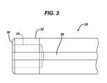
- FIG. 3is a side elevation view of the tip of the inserter of FIG. 2 ;
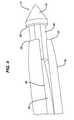
- FIG. 4is a side elevation view of tip of the inserter of FIG. 2 with the suture anchor of FIG. 1 loaded therein;
- FIG. 5is a perspective view of an alternative inserter according to the present invention for use with the suture anchor of FIG. 1 ;
- FIG. 6is a side elevation view of a humeral head showing the inserter of FIG. 5 in position for use;
- FIG. 7is a side elevation view of the humeral head of FIG. 6 in cross-section.
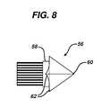
- FIG. 8is a side elevation view of an alternative embodiment of an anchor element of a suture anchor according to the present invention.
- FIG. 1shows a suture anchor 10 according to the present invention. It comprises a first anchor element 12 and second anchor element 14 interconnected by a flexible cord 16 .
- Each anchor member 12 , 14comprises a distal conical tip 18 and a proximal tubular body 20 swaged onto the cord 16 .
- a proximally facing annular flange 22interfaces between the tip 18 and the body 20 .
- a plurality of flexible barbs 24can optionally be disposed on the cord 16 adjacent the anchor elements 12 and 14 with a central section 25 being free of barbs.
- an inserter 26comprises an elongated shaft 28 having a proximal handle 30 and narrowing to a distal tip 32 .
- a distally facing socket 34is sized to receive the body 20 of one of the anchor elements 12 , 14 .
- An axial slotted cannulation 36runs from the tip 32 up the shaft 28 to accommodate and allow the lateral release of the cord 16 .
- a distal end 38 of the inserter, surrounding the socket 34is adapted to abut the flange 22 on the anchor elements 12 , 14 , as best seen in FIG. 4 .
- the anchor element 12is shown partially pulled out of the socket in FIG. 4 to more clearly show the flange 22 and distal end 38 . In use they will abut one another.
- the barbs 24are held in a retracted position within the cannulation 36 .
- FIG. 5shows an alternative embodiment of an inserter 40 having first and second parallel curved shafts 42 and 44 , and a handle 45 , with the first anchor element 12 loaded into a tip 46 of the first shaft 42 and the second anchor element 14 loaded into a tip 48 of the second shaft 44 .
- FIGS. 6 and 7illustrate a humeral head 50 and rotator cuff tendon 52 .
- the tendon 52is approximated to the desired location with a tendon grasper (not shown).
- the pre-loaded inserter 40is placed against the tendon and its angle adjusted to achieve a proper trajectory into the humeral head 50 .
- the inserter 40is then hammered to drive the shafts 42 and 44 into the humeral head 50 thereby driving the anchor elements 12 and 14 therein until the central section 25 of the cord 16 snugly holds the tendon 52 to the humeral head 50 .
- the anchor elements 12 and 14travel in from the tuberosity adjacent the tendon 52 and travel medially along a curved path but stop prior to breeching the articular surface and lodge deeply into the dense interior bone.
- the desired depth and anglecan be determined via pre-operative X-rays or other assessment of the geometry of the humeral head 50 . Depth markings, stops or other techniques can be employed to ensure proper depth.
- the inserter 40can be provided to a surgeon in various lengths and perhaps levels of curvature (including straight) so that the surgeon can choose based upon the geometry of the patient's humeral head 50 . After the anchor elements 12 and 14 are inserted to the desired location, the inserter 40 is removed leaving the suture anchor 10 in place.
- FIG. 7shows a typical bone density distribution in an osteoporotic bone, illustrating the advantages of the present invention.
- the bone density in the head 50 near tendon 52is significantly less than in a more medial bone area 54 .
- a typical prior suture anchorwould be placed into the less dense bone just below the tendon 52 or just lateral of its edge, also of low bone density.
- the suture anchor 10travels deeply and medially into the humeral head into the more dense bone area 54 .
- the anchor elements 12 and 14can be smaller than a traditional suture anchor which would be employed to hold the same tendon 52 due to the enhanced holding from their depth in the tissue and the superior bone into which they are placed. For a rotator cuff repair they may be sized to fit with an introducer the equivalent of a 15 to 18 gauge needle.
- the anchor elements 12 and 14can be formed of materials suitable for suture anchors such as stainless steel, titanium, PEEK, Polylactic Acid (PLA), Polylactic/polyglycolic Acid (PLGA), and mixtures with TriCalcium Phosphate (TCP) along with other materials as will be appreciated by those of skill in the art.
- an anchor element 56having a body 58 and sharp tip 60 with multiple barbs 62 to enhance the holding of the anchor element 56 into bone.
- an anchor elementcould be detachable from the cord 16 , such as being part of an inserter, or be quickly absorbable into the tissue, in either event to not add appreciable to the fixation but rather leave that function to the cord 16 .
- the cord 16can be standard suture, or barbed suture, of either the absorbent or non-absorbent varieties. ORTHOCORD suture available from DePuy Mitek of Raynham, Mass. could be employed.
- the cord 16could also be a metal wire, particularly a braided wire preferably with barbs. Alternatively, or additionally, the suture or wire could be treated or coated to enhance its coefficient of friction with bone.
- the inventionpreferably includes two or more anchor elements 12 and 14 interconnected by a cord 16 .
- a cord 16could comprise a single anchor element with a cord trailing therefrom.
- the cordcould be connected, such as after the anchor element is implanted, with another cord from another single anchor element, suture anchor or to a different type of suture anchor or to a suture from a different suture anchor.
- the cordcould be suture and it could be passed up from the implanted anchor element, out through the tendon 52 and over to a self-locking suture anchor (such as disclosed in U.S. Pat. No. 6,770,073) implanted at a different location, perhaps lateral of the tendon 52 , and then tensioned and locked to the self-locking anchor.
- One such self-locking anchoris the VERSALOK suture anchor available from DePuy Mitek of Raynham, Mass. While described most fully for a rotator cuff repair it is envisioned that the present invention would be useful for many other soft tissue repair procedures, especially where bone quality at the site of repair is degraded. It may also have utility for fracture or other bone repairs.
- the inventionhas been described with reference to the preferred embodiments. Obviously, modifications and alterations will occur to others upon reading and understanding the preceding detailed description. It is intended that the invention be construed as including all such modifications and alterations insofar as they come within the scope of the appended claims or the equivalents thereof.
- the cord 16could be of adjustable length or be separated into portions which could then be tied or otherwise connected together or to other suture anchors etc.
- barbs 24 and or even the anchor elements 12 and 14 fixationcould come from a portion of suture or attachment that expands in contact with bodily fluid.
- the anchor elements 12 and 14can comprise any type of body that an inserter can push against for delivery into the bone, e.g., an overhand knot, a folded suture, thermally reformed suture tips, etc.
Landscapes
- Health & Medical Sciences (AREA)
- Life Sciences & Earth Sciences (AREA)
- Surgery (AREA)
- Animal Behavior & Ethology (AREA)
- General Health & Medical Sciences (AREA)
- Engineering & Computer Science (AREA)
- Biomedical Technology (AREA)
- Heart & Thoracic Surgery (AREA)
- Veterinary Medicine (AREA)
- Public Health (AREA)
- Rheumatology (AREA)
- Medical Informatics (AREA)
- Molecular Biology (AREA)
- Nuclear Medicine, Radiotherapy & Molecular Imaging (AREA)
- Orthopedic Medicine & Surgery (AREA)
- Rehabilitation Therapy (AREA)
- Cardiology (AREA)
- Oral & Maxillofacial Surgery (AREA)
- Transplantation (AREA)
- Vascular Medicine (AREA)
- Surgical Instruments (AREA)
Abstract
Description
Claims (13)
Priority Applications (1)
| Application Number | Priority Date | Filing Date | Title |
|---|---|---|---|
| US13/832,875US9486201B2 (en) | 2012-09-27 | 2013-03-15 | Directionally specific bone anchors and method |
Applications Claiming Priority (2)
| Application Number | Priority Date | Filing Date | Title |
|---|---|---|---|
| US201261706199P | 2012-09-27 | 2012-09-27 | |
| US13/832,875US9486201B2 (en) | 2012-09-27 | 2013-03-15 | Directionally specific bone anchors and method |
Publications (2)
| Publication Number | Publication Date |
|---|---|
| US20140100609A1 US20140100609A1 (en) | 2014-04-10 |
| US9486201B2true US9486201B2 (en) | 2016-11-08 |
Family
ID=50433292
Family Applications (1)
| Application Number | Title | Priority Date | Filing Date |
|---|---|---|---|
| US13/832,875Expired - Fee RelatedUS9486201B2 (en) | 2012-09-27 | 2013-03-15 | Directionally specific bone anchors and method |
Country Status (1)
| Country | Link |
|---|---|
| US (1) | US9486201B2 (en) |
Citations (42)
| Publication number | Priority date | Publication date | Assignee | Title |
|---|---|---|---|---|
| US3981051A (en) | 1970-03-16 | 1976-09-21 | Brumlik George C | Bristle-like gripping device |
| US4198734A (en) | 1972-04-04 | 1980-04-22 | Brumlik George C | Self-gripping devices with flexible self-gripping means and method |
| US4738255A (en) | 1986-04-07 | 1988-04-19 | Biotron Labs, Inc. | Suture anchor system |
| US4899743A (en) | 1987-12-15 | 1990-02-13 | Mitek Surgical Products, Inc. | Suture anchor installation tool |
| US5053047A (en) | 1989-05-16 | 1991-10-01 | Inbae Yoon | Suture devices particularly useful in endoscopic surgery and methods of suturing |
| US5196022A (en) | 1988-12-12 | 1993-03-23 | Ethicon, Inc. | Ligature system for use in endoscopic surgery, ligature and handling instrument for said system |
| US5222976A (en) | 1989-05-16 | 1993-06-29 | Inbae Yoon | Suture devices particularly useful in endoscopic surgery |
| US5269783A (en) | 1991-05-13 | 1993-12-14 | United States Surgical Corporation | Device and method for repairing torn tissue |
| US5425747A (en) | 1993-10-12 | 1995-06-20 | Brotz; Gregory R. | Suture |
| US5584859A (en) | 1993-10-12 | 1996-12-17 | Brotz; Gregory R. | Suture assembly |
| US6146387A (en) | 1998-08-26 | 2000-11-14 | Linvatec Corporation | Cannulated tissue anchor system |
| US6241747B1 (en) | 1993-05-03 | 2001-06-05 | Quill Medical, Inc. | Barbed Bodily tissue connector |
| US6264675B1 (en) | 2000-02-04 | 2001-07-24 | Gregory R. Brotz | Single suture structure |
| US6328758B1 (en) | 1998-04-21 | 2001-12-11 | Tornier Sa | Suture anchor with reversible expansion |
| US6599310B2 (en) | 2001-06-29 | 2003-07-29 | Quill Medical, Inc. | Suture method |
| US6692499B2 (en) | 1997-07-02 | 2004-02-17 | Linvatec Biomaterials Oy | Surgical fastener for tissue treatment |
| US20040088003A1 (en) | 2002-09-30 | 2004-05-06 | Leung Jeffrey C. | Barbed suture in combination with surgical needle |
| US6770073B2 (en) | 1999-07-23 | 2004-08-03 | Depuy Mitek, Inc. | System and method for attaching soft tissue to bone |
| US6773450B2 (en) | 2002-08-09 | 2004-08-10 | Quill Medical, Inc. | Suture anchor and method |
| US20050182406A1 (en) | 2004-01-23 | 2005-08-18 | Orbay Jorge L. | System for stabilization of fractures of convex articular bone surfaces including subchondral support structure |
| US20050182405A1 (en) | 2004-01-23 | 2005-08-18 | Orbay Jorge L. | System for stabilization of fractures of convex articular bone surfaces including subchondral support structure |
| US20060235413A1 (en) | 2004-12-07 | 2006-10-19 | Arthrotek, Inc. | Expanding suture anchor having an actuator pin |
| US20060253119A1 (en)* | 2005-05-04 | 2006-11-09 | Sascha Berberich | Device for inserting an anchoring element and a suture thread into a bone |
| US20070005109A1 (en)* | 2005-06-29 | 2007-01-04 | Popadiuk Nicholas M | Barbed suture |
| US20070038249A1 (en)* | 2004-06-30 | 2007-02-15 | Alwin Kolster | Suture for wound closure, tissue approximation, tissue support, suspension and/or fixation |
| US20070038222A1 (en) | 2005-04-29 | 2007-02-15 | Jmea Corporation | Tissue Repair System |
| US20070093835A1 (en) | 2005-09-19 | 2007-04-26 | Orbay Jorge L | Bone Fixation Plate with Complex Suture Anchor Locations |
| US7303577B1 (en) | 2003-02-05 | 2007-12-04 | Dean John C | Apparatus and method for use in repairs of injured soft tissue |
| US20070293866A1 (en) | 2006-05-12 | 2007-12-20 | Dieter Stoeckel | Bone anchor system and method of use |
| US20080009871A1 (en) | 2006-06-27 | 2008-01-10 | Orbay Jorge L | Bone Plate Clamp |
| US7361179B2 (en) | 2004-04-22 | 2008-04-22 | Ethicon, Inc. | Sternal closure device and method |
| US20080161805A1 (en) | 2006-11-22 | 2008-07-03 | Sonoma Orthopedic Products, Inc. | Fracture fixation device, tools and methods |
| US20090118734A1 (en)* | 2005-04-29 | 2009-05-07 | Jmea Corporation | Implantation System for Tissue Repair |
| US20090125070A1 (en) | 2007-11-02 | 2009-05-14 | Sixto Jr Robert | Fracture Fixation Plate for the Coronoid of the Proximal Ulna |
| US20090192545A1 (en)* | 2008-01-30 | 2009-07-30 | William Buchanan Workman | Curved suture anchor guide and method of use |
| US7601164B2 (en) | 2004-04-07 | 2009-10-13 | Tze Liang Woffles Wu | Surgical thread |
| US20090287245A1 (en) | 2008-05-14 | 2009-11-19 | Isaac Ostrovsky | Surgical Composite Barbed Suture |
| US20100030135A1 (en) | 2006-05-11 | 2010-02-04 | Michael David Mitchell | Method and apparatus for anchoring bone screws and injecting many types of high viscosity materials in areas surrounding bone |
| US7662864B2 (en) | 2003-06-04 | 2010-02-16 | Rutgers, The State University Of New Jersey | Solution polymerization processes to prepare a polymer that degrades to release a physiologically active agent |
| US7691135B2 (en) | 1999-03-11 | 2010-04-06 | Endologix, Inc. | Single puncture bifurcation graft deployment system |
| US20110213417A1 (en)* | 2007-09-12 | 2011-09-01 | Foerster Seth A | Implant and delivery system for soft tissue repair |
| US20130006276A1 (en)* | 2009-07-17 | 2013-01-03 | Andrew Lantz | Method and apparatus for re-attaching the labrum to the acetabulum, including the provision and use of a novel suture anchor system |
- 2013
- 2013-03-15USUS13/832,875patent/US9486201B2/ennot_activeExpired - Fee Related
Patent Citations (48)
| Publication number | Priority date | Publication date | Assignee | Title |
|---|---|---|---|---|
| US3981051A (en) | 1970-03-16 | 1976-09-21 | Brumlik George C | Bristle-like gripping device |
| US4198734A (en) | 1972-04-04 | 1980-04-22 | Brumlik George C | Self-gripping devices with flexible self-gripping means and method |
| US4738255A (en) | 1986-04-07 | 1988-04-19 | Biotron Labs, Inc. | Suture anchor system |
| US4899743A (en) | 1987-12-15 | 1990-02-13 | Mitek Surgical Products, Inc. | Suture anchor installation tool |
| US5196022A (en) | 1988-12-12 | 1993-03-23 | Ethicon, Inc. | Ligature system for use in endoscopic surgery, ligature and handling instrument for said system |
| US5330503A (en) | 1989-05-16 | 1994-07-19 | Inbae Yoon | Spiral suture needle for joining tissue |
| US5222976A (en) | 1989-05-16 | 1993-06-29 | Inbae Yoon | Suture devices particularly useful in endoscopic surgery |
| US5053047A (en) | 1989-05-16 | 1991-10-01 | Inbae Yoon | Suture devices particularly useful in endoscopic surgery and methods of suturing |
| US5269783A (en) | 1991-05-13 | 1993-12-14 | United States Surgical Corporation | Device and method for repairing torn tissue |
| US5374268A (en) | 1991-05-13 | 1994-12-20 | United States Surgical Corporation | Device and method for repairing torn tissue |
| US7226468B2 (en) | 1993-05-03 | 2007-06-05 | Quill Medical, Inc. | Barbed bodily tissue connector |
| US6241747B1 (en) | 1993-05-03 | 2001-06-05 | Quill Medical, Inc. | Barbed Bodily tissue connector |
| US5425747A (en) | 1993-10-12 | 1995-06-20 | Brotz; Gregory R. | Suture |
| US5584859A (en) | 1993-10-12 | 1996-12-17 | Brotz; Gregory R. | Suture assembly |
| US6692499B2 (en) | 1997-07-02 | 2004-02-17 | Linvatec Biomaterials Oy | Surgical fastener for tissue treatment |
| US6328758B1 (en) | 1998-04-21 | 2001-12-11 | Tornier Sa | Suture anchor with reversible expansion |
| US6146387A (en) | 1998-08-26 | 2000-11-14 | Linvatec Corporation | Cannulated tissue anchor system |
| US6346109B1 (en) | 1998-08-26 | 2002-02-12 | Linvatec Corporation | Cannulated tissue anchor system |
| US6290702B1 (en) | 1998-08-26 | 2001-09-18 | Linvatec Corporation | Cannulated tissue anchor system |
| US7691135B2 (en) | 1999-03-11 | 2010-04-06 | Endologix, Inc. | Single puncture bifurcation graft deployment system |
| US6770073B2 (en) | 1999-07-23 | 2004-08-03 | Depuy Mitek, Inc. | System and method for attaching soft tissue to bone |
| US6264675B1 (en) | 2000-02-04 | 2001-07-24 | Gregory R. Brotz | Single suture structure |
| US6599310B2 (en) | 2001-06-29 | 2003-07-29 | Quill Medical, Inc. | Suture method |
| US6773450B2 (en) | 2002-08-09 | 2004-08-10 | Quill Medical, Inc. | Suture anchor and method |
| US20040088003A1 (en) | 2002-09-30 | 2004-05-06 | Leung Jeffrey C. | Barbed suture in combination with surgical needle |
| US7303577B1 (en) | 2003-02-05 | 2007-12-04 | Dean John C | Apparatus and method for use in repairs of injured soft tissue |
| US7662864B2 (en) | 2003-06-04 | 2010-02-16 | Rutgers, The State University Of New Jersey | Solution polymerization processes to prepare a polymer that degrades to release a physiologically active agent |
| US20050182405A1 (en) | 2004-01-23 | 2005-08-18 | Orbay Jorge L. | System for stabilization of fractures of convex articular bone surfaces including subchondral support structure |
| US20050182406A1 (en) | 2004-01-23 | 2005-08-18 | Orbay Jorge L. | System for stabilization of fractures of convex articular bone surfaces including subchondral support structure |
| US7601164B2 (en) | 2004-04-07 | 2009-10-13 | Tze Liang Woffles Wu | Surgical thread |
| US7361179B2 (en) | 2004-04-22 | 2008-04-22 | Ethicon, Inc. | Sternal closure device and method |
| US20070038249A1 (en)* | 2004-06-30 | 2007-02-15 | Alwin Kolster | Suture for wound closure, tissue approximation, tissue support, suspension and/or fixation |
| US20060235413A1 (en) | 2004-12-07 | 2006-10-19 | Arthrotek, Inc. | Expanding suture anchor having an actuator pin |
| US20070038222A1 (en) | 2005-04-29 | 2007-02-15 | Jmea Corporation | Tissue Repair System |
| US20090118734A1 (en)* | 2005-04-29 | 2009-05-07 | Jmea Corporation | Implantation System for Tissue Repair |
| US20060253119A1 (en)* | 2005-05-04 | 2006-11-09 | Sascha Berberich | Device for inserting an anchoring element and a suture thread into a bone |
| US20070005109A1 (en)* | 2005-06-29 | 2007-01-04 | Popadiuk Nicholas M | Barbed suture |
| US20070093835A1 (en) | 2005-09-19 | 2007-04-26 | Orbay Jorge L | Bone Fixation Plate with Complex Suture Anchor Locations |
| US7604657B2 (en) | 2005-09-19 | 2009-10-20 | Depuy Products, Inc. | Bone fixation plate with complex suture anchor locations |
| US20100030135A1 (en) | 2006-05-11 | 2010-02-04 | Michael David Mitchell | Method and apparatus for anchoring bone screws and injecting many types of high viscosity materials in areas surrounding bone |
| US20070293866A1 (en) | 2006-05-12 | 2007-12-20 | Dieter Stoeckel | Bone anchor system and method of use |
| US20080009871A1 (en) | 2006-06-27 | 2008-01-10 | Orbay Jorge L | Bone Plate Clamp |
| US20080161805A1 (en) | 2006-11-22 | 2008-07-03 | Sonoma Orthopedic Products, Inc. | Fracture fixation device, tools and methods |
| US20110213417A1 (en)* | 2007-09-12 | 2011-09-01 | Foerster Seth A | Implant and delivery system for soft tissue repair |
| US20090125070A1 (en) | 2007-11-02 | 2009-05-14 | Sixto Jr Robert | Fracture Fixation Plate for the Coronoid of the Proximal Ulna |
| US20090192545A1 (en)* | 2008-01-30 | 2009-07-30 | William Buchanan Workman | Curved suture anchor guide and method of use |
| US20090287245A1 (en) | 2008-05-14 | 2009-11-19 | Isaac Ostrovsky | Surgical Composite Barbed Suture |
| US20130006276A1 (en)* | 2009-07-17 | 2013-01-03 | Andrew Lantz | Method and apparatus for re-attaching the labrum to the acetabulum, including the provision and use of a novel suture anchor system |
Also Published As
| Publication number | Publication date |
|---|---|
| US20140100609A1 (en) | 2014-04-10 |
Similar Documents
| Publication | Publication Date | Title |
|---|---|---|
| US7217279B2 (en) | Suture loop anchor | |
| US9226743B2 (en) | Applicator for suture/button construct with positive retention and control | |
| US8348960B2 (en) | Applicator for suture/button construct | |
| EP2316379B1 (en) | Partial thickness rotator cuff repair system | |
| US8663279B2 (en) | Swivel anchor for knotless fixation of tissue | |
| US10016195B2 (en) | Suture leader | |
| US9907591B2 (en) | Strand for minimally invasive removal of T-anchor | |
| JP4717379B2 (en) | Suture securing device with improved drive head | |
| CN103892879B (en) | Multi-piece anchor inserter | |
| US20080109037A1 (en) | Press fit suture anchor and inserter assembly | |
| US20080275553A1 (en) | External bullet anchor apparatus and method for use in surgical repair of ligament or tendon | |
| JP2005144180A5 (en) | ||
| EP2316380A1 (en) | Dual cannula system for partial thickness rotator cuff repair | |
| JP6542917B2 (en) | Suture anchor system with threaded plug | |
| US20150088198A1 (en) | Self-assembling suture anchor assembly, surgical kit, and surgical repair method | |
| CN109077762B (en) | Fingerstall for collapsed suture loops | |
| US8114094B2 (en) | Device for introducing an anchor element into a bone | |
| US9486201B2 (en) | Directionally specific bone anchors and method | |
| CN106999181A (en) | Suture anchor with reinforcement with ribbing | |
| US20220338856A1 (en) | Knotless suture anchors |
Legal Events
| Date | Code | Title | Description |
|---|---|---|---|
| AS | Assignment | Owner name:DEPUY MITEK, LLC, MASSACHUSETTS Free format text:ASSIGNMENT OF ASSIGNORS INTEREST;ASSIGNOR:SPENCINER, DAVID B.;REEL/FRAME:030103/0633 Effective date:20130326 | |
| STCF | Information on status: patent grant | Free format text:PATENTED CASE | |
| AS | Assignment | Owner name:DEPUY SYNTHES SALES, INC., MASSACHUSETTS Free format text:ASSIGNMENT OF ASSIGNORS INTEREST;ASSIGNOR:DEPUY MITEK, LLC;REEL/FRAME:048197/0069 Effective date:20141229 Owner name:DEPUY SYNTHES PRODUCTS, INC., MASSACHUSETTS Free format text:ASSIGNMENT OF ASSIGNORS INTEREST;ASSIGNOR:DEPUY SYNTHES SALES INC.;REEL/FRAME:048197/0142 Effective date:20141229 Owner name:DEPUY MITEK HOLDING CORPORATION, MASSACHUSETTS Free format text:ASSIGNMENT OF ASSIGNORS INTEREST;ASSIGNOR:DEPUY MITEK, LLC;REEL/FRAME:048197/0861 Effective date:20141229 Owner name:DEPUY SYNTHES PRODUCTS, LLC, MASSACHUSETTS Free format text:ASSIGNMENT OF ASSIGNORS INTEREST;ASSIGNOR:DEPUY SPINE, LLC;REEL/FRAME:048198/0497 Effective date:20141229 Owner name:SYNTHES USA, LLC, PENNSYLVANIA Free format text:ASSIGNMENT OF ASSIGNORS INTEREST;ASSIGNOR:DEPUY MITEK HOLDING CORPORATION;REEL/FRAME:048198/0860 Effective date:20141219 Owner name:DEPUY SYNTHES PRODUCTS, INC, MASSACHUSETTS Free format text:CHANGE OF NAME;ASSIGNOR:DEPUY SYNTHES PRODUCTS, LLC;REEL/FRAME:048198/0563 Effective date:20141219 Owner name:DEPUY SPINE, LLC, MASSACHUSETTS Free format text:ASSIGNMENT OF ASSIGNORS INTEREST;ASSIGNOR:SYNTHES USA, LLC;REEL/FRAME:048829/0673 Effective date:20141229 | |
| MAFP | Maintenance fee payment | Free format text:PAYMENT OF MAINTENANCE FEE, 4TH YEAR, LARGE ENTITY (ORIGINAL EVENT CODE: M1551); ENTITY STATUS OF PATENT OWNER: LARGE ENTITY Year of fee payment:4 | |
| LAPS | Lapse for failure to pay maintenance fees | Free format text:PATENT EXPIRED FOR FAILURE TO PAY MAINTENANCE FEES (ORIGINAL EVENT CODE: EXP.); ENTITY STATUS OF PATENT OWNER: LARGE ENTITY | |
| STCH | Information on status: patent discontinuation | Free format text:PATENT EXPIRED DUE TO NONPAYMENT OF MAINTENANCE FEES UNDER 37 CFR 1.362 | |
| FP | Lapsed due to failure to pay maintenance fee | Effective date:20241108 |