US9486162B2 - Spatial needle guidance system and associated methods - Google Patents
Spatial needle guidance system and associated methodsDownload PDFInfo
- Publication number
- US9486162B2 US9486162B2US12/986,804US98680411AUS9486162B2US 9486162 B2US9486162 B2US 9486162B2US 98680411 AUS98680411 AUS 98680411AUS 9486162 B2US9486162 B2US 9486162B2
- Authority
- US
- United States
- Prior art keywords
- needle
- sheath
- hub
- position marker
- hollow shaft
- Prior art date
- Legal status (The legal status is an assumption and is not a legal conclusion. Google has not performed a legal analysis and makes no representation as to the accuracy of the status listed.)
- Expired - Fee Related, expires
Links
Images


Classifications
- A—HUMAN NECESSITIES
- A61—MEDICAL OR VETERINARY SCIENCE; HYGIENE
- A61B—DIAGNOSIS; SURGERY; IDENTIFICATION
- A61B5/00—Measuring for diagnostic purposes; Identification of persons
- A61B5/14—Devices for taking samples of blood ; Measuring characteristics of blood in vivo, e.g. gas concentration within the blood, pH-value of blood
- A61B5/1405—Devices for taking blood samples
- A61B5/1422—Devices for taking blood samples provided with indicating means, e.g. for vein entry
- A—HUMAN NECESSITIES
- A61—MEDICAL OR VETERINARY SCIENCE; HYGIENE
- A61B—DIAGNOSIS; SURGERY; IDENTIFICATION
- A61B10/00—Instruments for taking body samples for diagnostic purposes; Other methods or instruments for diagnosis, e.g. for vaccination diagnosis, sex determination or ovulation-period determination; Throat striking implements
- A61B10/02—Instruments for taking cell samples or for biopsy
- A61B10/0233—Pointed or sharp biopsy instruments
- A—HUMAN NECESSITIES
- A61—MEDICAL OR VETERINARY SCIENCE; HYGIENE
- A61B—DIAGNOSIS; SURGERY; IDENTIFICATION
- A61B17/00—Surgical instruments, devices or methods
- A61B17/34—Trocars; Puncturing needles
- A61B17/3403—Needle locating or guiding means
- A—HUMAN NECESSITIES
- A61—MEDICAL OR VETERINARY SCIENCE; HYGIENE
- A61B—DIAGNOSIS; SURGERY; IDENTIFICATION
- A61B17/00—Surgical instruments, devices or methods
- A61B17/34—Trocars; Puncturing needles
- A61B17/3415—Trocars; Puncturing needles for introducing tubes or catheters, e.g. gastrostomy tubes, drain catheters
- A—HUMAN NECESSITIES
- A61—MEDICAL OR VETERINARY SCIENCE; HYGIENE
- A61B—DIAGNOSIS; SURGERY; IDENTIFICATION
- A61B17/00—Surgical instruments, devices or methods
- A61B17/34—Trocars; Puncturing needles
- A61B17/3468—Trocars; Puncturing needles for implanting or removing devices, e.g. prostheses, implants, seeds, wires
- A—HUMAN NECESSITIES
- A61—MEDICAL OR VETERINARY SCIENCE; HYGIENE
- A61B—DIAGNOSIS; SURGERY; IDENTIFICATION
- A61B34/00—Computer-aided surgery; Manipulators or robots specially adapted for use in surgery
- A61B34/20—Surgical navigation systems; Devices for tracking or guiding surgical instruments, e.g. for frameless stereotaxis
- A—HUMAN NECESSITIES
- A61—MEDICAL OR VETERINARY SCIENCE; HYGIENE
- A61B—DIAGNOSIS; SURGERY; IDENTIFICATION
- A61B5/00—Measuring for diagnostic purposes; Identification of persons
- A61B5/15—Devices for taking samples of blood
- A61B5/150007—Details
- A61B5/150015—Source of blood
- A61B5/15003—Source of blood for venous or arterial blood
- A—HUMAN NECESSITIES
- A61—MEDICAL OR VETERINARY SCIENCE; HYGIENE
- A61B—DIAGNOSIS; SURGERY; IDENTIFICATION
- A61B5/00—Measuring for diagnostic purposes; Identification of persons
- A61B5/15—Devices for taking samples of blood
- A61B5/150007—Details
- A61B5/150374—Details of piercing elements or protective means for preventing accidental injuries by such piercing elements
- A61B5/150381—Design of piercing elements
- A61B5/150389—Hollow piercing elements, e.g. canulas, needles, for piercing the skin
- A61B5/150404—Specific design of proximal end
- A—HUMAN NECESSITIES
- A61—MEDICAL OR VETERINARY SCIENCE; HYGIENE
- A61B—DIAGNOSIS; SURGERY; IDENTIFICATION
- A61B5/00—Measuring for diagnostic purposes; Identification of persons
- A61B5/15—Devices for taking samples of blood
- A61B5/150007—Details
- A61B5/150374—Details of piercing elements or protective means for preventing accidental injuries by such piercing elements
- A61B5/150381—Design of piercing elements
- A61B5/150503—Single-ended needles
- A61B5/150519—Details of construction of hub, i.e. element used to attach the single-ended needle to a piercing device or sampling device
- A—HUMAN NECESSITIES
- A61—MEDICAL OR VETERINARY SCIENCE; HYGIENE
- A61B—DIAGNOSIS; SURGERY; IDENTIFICATION
- A61B5/00—Measuring for diagnostic purposes; Identification of persons
- A61B5/15—Devices for taking samples of blood
- A61B5/150007—Details
- A61B5/150374—Details of piercing elements or protective means for preventing accidental injuries by such piercing elements
- A61B5/150534—Design of protective means for piercing elements for preventing accidental needle sticks, e.g. shields, caps, protectors, axially extensible sleeves, pivotable protective sleeves
- A61B5/150572—Pierceable protectors, e.g. shields, caps, sleeves or films, e.g. for hygienic purposes
- A—HUMAN NECESSITIES
- A61—MEDICAL OR VETERINARY SCIENCE; HYGIENE
- A61B—DIAGNOSIS; SURGERY; IDENTIFICATION
- A61B5/00—Measuring for diagnostic purposes; Identification of persons
- A61B5/15—Devices for taking samples of blood
- A61B5/150007—Details
- A61B5/150748—Having means for aiding positioning of the piercing device at a location where the body is to be pierced
- A—HUMAN NECESSITIES
- A61—MEDICAL OR VETERINARY SCIENCE; HYGIENE
- A61B—DIAGNOSIS; SURGERY; IDENTIFICATION
- A61B5/00—Measuring for diagnostic purposes; Identification of persons
- A61B5/15—Devices for taking samples of blood
- A61B5/153—Devices specially adapted for taking samples of venous or arterial blood, e.g. with syringes
- A61B5/1535—Devices specially adapted for taking samples of venous or arterial blood, e.g. with syringes comprising means for indicating vein or arterial entry
- A—HUMAN NECESSITIES
- A61—MEDICAL OR VETERINARY SCIENCE; HYGIENE
- A61B—DIAGNOSIS; SURGERY; IDENTIFICATION
- A61B17/00—Surgical instruments, devices or methods
- A61B17/34—Trocars; Puncturing needles
- A61B17/3498—Valves therefor, e.g. flapper valves, slide valves
- A—HUMAN NECESSITIES
- A61—MEDICAL OR VETERINARY SCIENCE; HYGIENE
- A61B—DIAGNOSIS; SURGERY; IDENTIFICATION
- A61B17/00—Surgical instruments, devices or methods
- A61B2017/0046—Surgical instruments, devices or methods with a releasable handle; with handle and operating part separable
- A61B2017/00469—Surgical instruments, devices or methods with a releasable handle; with handle and operating part separable for insertion of instruments, e.g. guide wire, optical fibre
- A—HUMAN NECESSITIES
- A61—MEDICAL OR VETERINARY SCIENCE; HYGIENE
- A61B—DIAGNOSIS; SURGERY; IDENTIFICATION
- A61B17/00—Surgical instruments, devices or methods
- A61B17/34—Trocars; Puncturing needles
- A61B17/3403—Needle locating or guiding means
- A61B2017/3413—Needle locating or guiding means guided by ultrasound
- A—HUMAN NECESSITIES
- A61—MEDICAL OR VETERINARY SCIENCE; HYGIENE
- A61B—DIAGNOSIS; SURGERY; IDENTIFICATION
- A61B17/00—Surgical instruments, devices or methods
- A61B17/34—Trocars; Puncturing needles
- A61B2017/347—Locking means, e.g. for locking instrument in cannula
- A—HUMAN NECESSITIES
- A61—MEDICAL OR VETERINARY SCIENCE; HYGIENE
- A61B—DIAGNOSIS; SURGERY; IDENTIFICATION
- A61B34/00—Computer-aided surgery; Manipulators or robots specially adapted for use in surgery
- A61B34/20—Surgical navigation systems; Devices for tracking or guiding surgical instruments, e.g. for frameless stereotaxis
- A61B2034/2046—Tracking techniques
- A61B2034/2051—Electromagnetic tracking systems
- A—HUMAN NECESSITIES
- A61—MEDICAL OR VETERINARY SCIENCE; HYGIENE
- A61B—DIAGNOSIS; SURGERY; IDENTIFICATION
- A61B34/00—Computer-aided surgery; Manipulators or robots specially adapted for use in surgery
- A61B34/20—Surgical navigation systems; Devices for tracking or guiding surgical instruments, e.g. for frameless stereotaxis
- A61B2034/2046—Tracking techniques
- A61B2034/2055—Optical tracking systems
- A—HUMAN NECESSITIES
- A61—MEDICAL OR VETERINARY SCIENCE; HYGIENE
- A61B—DIAGNOSIS; SURGERY; IDENTIFICATION
- A61B90/00—Instruments, implements or accessories specially adapted for surgery or diagnosis and not covered by any of the groups A61B1/00 - A61B50/00, e.g. for luxation treatment or for protecting wound edges
- A61B90/36—Image-producing devices or illumination devices not otherwise provided for
- A61B90/37—Surgical systems with images on a monitor during operation
- A61B2090/378—Surgical systems with images on a monitor during operation using ultrasound
- A—HUMAN NECESSITIES
- A61—MEDICAL OR VETERINARY SCIENCE; HYGIENE
- A61B—DIAGNOSIS; SURGERY; IDENTIFICATION
- A61B90/00—Instruments, implements or accessories specially adapted for surgery or diagnosis and not covered by any of the groups A61B1/00 - A61B50/00, e.g. for luxation treatment or for protecting wound edges
- A61B90/39—Markers, e.g. radio-opaque or breast lesions markers
- A61B2090/3937—Visible markers
- A—HUMAN NECESSITIES
- A61—MEDICAL OR VETERINARY SCIENCE; HYGIENE
- A61B—DIAGNOSIS; SURGERY; IDENTIFICATION
- A61B90/00—Instruments, implements or accessories specially adapted for surgery or diagnosis and not covered by any of the groups A61B1/00 - A61B50/00, e.g. for luxation treatment or for protecting wound edges
- A61B90/39—Markers, e.g. radio-opaque or breast lesions markers
- A61B2090/397—Markers, e.g. radio-opaque or breast lesions markers electromagnetic other than visible, e.g. microwave
- A61B2090/3975—Markers, e.g. radio-opaque or breast lesions markers electromagnetic other than visible, e.g. microwave active
- A—HUMAN NECESSITIES
- A61—MEDICAL OR VETERINARY SCIENCE; HYGIENE
- A61B—DIAGNOSIS; SURGERY; IDENTIFICATION
- A61B5/00—Measuring for diagnostic purposes; Identification of persons
- A61B5/06—Devices, other than using radiation, for detecting or locating foreign bodies ; Determining position of diagnostic devices within or on the body of the patient
- A61B5/061—Determining position of a probe within the body employing means separate from the probe, e.g. sensing internal probe position employing impedance electrodes on the surface of the body
- A61B5/062—Determining position of a probe within the body employing means separate from the probe, e.g. sensing internal probe position employing impedance electrodes on the surface of the body using magnetic field
- A—HUMAN NECESSITIES
- A61—MEDICAL OR VETERINARY SCIENCE; HYGIENE
- A61B—DIAGNOSIS; SURGERY; IDENTIFICATION
- A61B5/00—Measuring for diagnostic purposes; Identification of persons
- A61B5/68—Arrangements of detecting, measuring or recording means, e.g. sensors, in relation to patient
- A61B5/6846—Arrangements of detecting, measuring or recording means, e.g. sensors, in relation to patient specially adapted to be brought in contact with an internal body part, i.e. invasive
- A61B5/6847—Arrangements of detecting, measuring or recording means, e.g. sensors, in relation to patient specially adapted to be brought in contact with an internal body part, i.e. invasive mounted on an invasive device
- A61B5/6848—Needles
- A61B5/6849—Needles in combination with a needle set
- A—HUMAN NECESSITIES
- A61—MEDICAL OR VETERINARY SCIENCE; HYGIENE
- A61B—DIAGNOSIS; SURGERY; IDENTIFICATION
- A61B8/00—Diagnosis using ultrasonic, sonic or infrasonic waves
- A61B8/08—Clinical applications
- A61B8/0833—Clinical applications involving detecting or locating foreign bodies or organic structures
- A61B8/0841—Clinical applications involving detecting or locating foreign bodies or organic structures for locating instruments
- A—HUMAN NECESSITIES
- A61—MEDICAL OR VETERINARY SCIENCE; HYGIENE
- A61B—DIAGNOSIS; SURGERY; IDENTIFICATION
- A61B8/00—Diagnosis using ultrasonic, sonic or infrasonic waves
- A61B8/42—Details of probe positioning or probe attachment to the patient
- A61B8/4245—Details of probe positioning or probe attachment to the patient involving determining the position of the probe, e.g. with respect to an external reference frame or to the patient
- A61B8/4254—Details of probe positioning or probe attachment to the patient involving determining the position of the probe, e.g. with respect to an external reference frame or to the patient using sensors mounted on the probe
- A—HUMAN NECESSITIES
- A61—MEDICAL OR VETERINARY SCIENCE; HYGIENE
- A61M—DEVICES FOR INTRODUCING MEDIA INTO, OR ONTO, THE BODY; DEVICES FOR TRANSDUCING BODY MEDIA OR FOR TAKING MEDIA FROM THE BODY; DEVICES FOR PRODUCING OR ENDING SLEEP OR STUPOR
- A61M5/00—Devices for bringing media into the body in a subcutaneous, intra-vascular or intramuscular way; Accessories therefor, e.g. filling or cleaning devices, arm-rests
- A61M5/42—Devices for bringing media into the body in a subcutaneous, intra-vascular or intramuscular way; Accessories therefor, e.g. filling or cleaning devices, arm-rests having means for desensitising skin, for protruding skin to facilitate piercing, or for locating point where body is to be pierced
- A61M5/427—Locating point where body is to be pierced, e.g. vein location means using ultrasonic waves, injection site templates
Definitions
- This inventionrelates to medical navigation technology. Embodiments of the invention have particular application in the fields of medical diagnosis and therapeutics involving the use of needles.
- Needlesare used in a wide range of medical applications. For example, needles are used in biopsy procedures.
- a biopsytypically involves identifying a tissue of interest, such as suspicious solid mass, a distortion in the structure of a body tissue, or an area of abnormal tissue change.
- a needlemay be inserted into the abnormality and used to withdraw a small tissue sample for investigation.
- needlesmay be used for biopsies.
- fine needle aspirationsmall hollow needles are used to extract cells from a location of interest.
- a core needleis a larger diameter needle which may be used to withdraw larger samples of tissue.
- Vacuum assisted devicesmay be used to collect multiple tissue samples during one needle insertion.
- medical imaging technologiesare used to assist in placing a guide wire into a location of interest to assist a surgeon in locating the abnormality for a surgical biopsy.
- a challenge in performing needle biopsies, or like proceduresis that the needle, or other thin member, and particularly the end thereof, must be placed at a desired location in the subject's body. Imaging of the subject's body and needle placed therein, such as ultrasound imaging or the like, may be used during needle insertion, and the resulting images used to help guide the needle to a desired location.
- imaging in any of these procedures, or like proceduresis that the needles are often very difficult to see in an image. This makes it difficult for a person taking the biopsy to ensure that the needle has reached its target.
- guiding the needle to place the tip of the needle at an area of a location shown in an imagecan take a significant amount of skill because the image does not always provide good feedback to the practitioner regarding exactly where the needle is placed and/or how the needle should be manipulated to cleanly enter tissue at the location. Also, the needle may not be visible in the image because all or part of the needle is out of the plane of the image.
- Accurate needle placementis also important in a variety of medical procedures that involve delivering substances into the body of a subject using needles. For example, accurate placement may be required for the introduction of a drug, such as an anesthetic, or a radioactive seed for cancer treatment or the like.
- a drugsuch as an anesthetic, or a radioactive seed for cancer treatment or the like.
- FIG. 1is a schematic view of an example ultrasound probe and biopsy assembly as may be used with the invention.
- FIG. 2is a side elevation view of a sheathed position marker assembly according to an example embodiment.
- FIG. 3Ais a cross-sectional view of a sheathed position marker assembly according to an example embodiment.
- FIG. 3Bis a cross-sectional view of a sheathed position marker assembly according to an example embodiment.
- FIG. 4is a cross-sectional view of a position tracked member assembly according to an example embodiment.
- FIG. 5Ais side elevation view of a connector base according to an example embodiment.
- FIG. 5Bis top plan view of the connector base depicted in FIG. 3A .
- FIG. 5Cis an end elevation view of the connector base depicted in FIG. 3A .
- FIG. 6Ais a side elevation view of a sheath according to an example embodiment.
- FIG. 6Bis a cross-section of the sheath depicted in FIG. 4A .
- FIG. 7is an isometric view of a nerve access needle according to an example embodiment.
- FIG. 8is an isometric view of a needle sheath assembly according to an example embodiment.
- FIG. 9is a cross section through a needle sheath assembly according to another example embodiment.
- FIGS. 10 and 10Aare cross sectional views through a needle sheath assembly with provision for the introduction of fluids according to another example embodiment.
- FIG. 11is an isometric exploded view of a needle sheath assembly according to another example embodiment.
- FIG. 12is a cross section through an example position sensor assembly showing how the position sensor assembly may be applied in combination with a sterile sleeve enclosure.
- One aspect of the inventionrelates to methods and apparatus to facilitate monitoring the location of the tip or other point on a thin elongate member such as a needle.
- Embodiments of such methods and apparatusmay be applied, for example, to monitor the position of the tip of a biopsy needle, the tip of a needle to be used to delivery anaesthetic or another fluid, the tip of a probe, the tip of a brachytherapy applicator, an electrode, a hollow guide for introducing other instruments, or the like.
- an image of tissues into which the needle is to be placedis registered to the coordinate system in which the position of the needle tip is to be monitored.
- the actual position of the needle tip, the desired location of the needle tip and anatomical structures within the tissuemay be displayed.
- FIG. 1shows an example application in which a position sensing system is provided.
- the position sensing systemmonitors positions of location markers that are associated with various implements.
- Various position sensing systemsare commercially available.
- a positioning sensing system 16monitors positions and orientations of an ultrasound probe 12 and a biopsy apparatus 19 .
- the position and orientation of probe 12are monitored by a 3D position sensor system 16 .
- the 3D position sensor system 16may include one or more position sensor base units and one or more markers carried on probe 12 .
- probe 12includes a plurality of position markers 15 .
- Position markers 15 A, 15 B, and 15 Care not located along a common line. Therefore, if the locations of position markers 15 A, 15 B, and 15 C are known, the position and orientation in space of probe 12 is uniquely determined. Since the particular cross section represented by an ultrasound image depends upon the current position and orientation of a transducer array 14 in probe 12 , the position and orientation of ultrasound images can be determined from the position and orientation in space of probe 12 .
- 3D position sensor system 16The positions of location markers 15 relative to a global coordinate system are measured by 3D position sensor system 16 .
- the sensor systemincludes a position base unit 17 .
- 3D position base unit 17 and position markers 15may comprise any suitable technology.
- 3D position base unit 17may detect electromagnetic or other fields emitted by position markers 15 or vice versa.
- position base unit 17generates a magnetic field that is sensed by position markers 15 .
- a 3D position sensing systemmay, for example, comprise a medSAFETM or drive BAYTM position sensor available from Ascension Technology corporation of Burlington, Vt., USA.
- Some 3D position sensing technologiespermit both the location and orientation of a single position marker to be determined. Where such 3D position sensing technologies are used, fewer position markers 15 are required to determine the location and orientation of an implement such as probe 12 than would be the case for position markers for which only position is determined.
- a single 6 degree of freedom position markermay be used in a compatible position sensor system to obtain both position and orientation information for a probe 12 .
- a 3 degree of freedom position markermay be used in a compatible position sensor system to obtain position information in three coordinate directions.
- one or more redundant position markers 15may be provided. In embodiments which provide more position markers than are required to identify position and orientation of probe 12 , positions of the additional position markers may be monitored by 3D position base unit 17 and used to provide information regarding the position and orientation of probe 12 of enhanced accuracy.
- the ultrasound systemmay generate images of tissues in the field of view of probe 12 .
- images of tissues in the field of view of probe 12For example, in so-called B-mode imaging, a 2D image of a selected cross-section of the patient's body is generated. Because the position and orientation of transducer array 14 is fixed in probe 12 , the particular cross section represented by an ultrasound image depends upon the current position and orientation of probe 12 relative to the patient's body. Moving probe 12 relative to the patient's body will result in a different cross section being imaged.
- FIG. 1shows two scattering locations, P 1 and P 2 .
- P 1is located at position R 1 , ⁇ 1 .
- P 2is at location R 2 , ⁇ 2 . These locations are both determined with reference to a coordinate system that can be considered to be attached to probe 12 .
- FIG. 1also shows a biopsy apparatus 19 which includes a handle 20 and a needle 21 .
- Biopsy apparatus 19includes one or more position markers 15 .
- there are two position markers 15individually identified as 15 D and 15 E.
- position markers 15 D and 15 Eare located so that they correspond to reference positions on an extension of a longitudinal axis of needle 21 . Neglecting rotations about the axis of needle 21 , the position and orientation of needle 21 can be uniquely determined if the positions of position markers 15 D and 15 E are known.
- the reference positions of location markers 15 D and 15 Eare monitored by 3D position sensor system 16 .
- the apparatus illustrated in FIG. 1may facilitate the placing of needle 21 into the body of patient P such that needle 21 may be used to acquire a tissue sample or place something at a desired location within patient P.
- needle 21may be used to acquire a tissue sample or place something at a desired location within patient P.
- an ultrasound image 23is generated from ultrasound data acquired by probe 12
- the precise location and orientation of needle 21 relative to that ultrasound imagecan be determined from the known locations of position markers 15 on probe 12 and biopsy assembly 19 . Having this information allows the location of needle 21 to be illustrated clearly on image 23 (even if the ultrasound echos do not provide a clear image of needle 21 ).
- needle 21is represented by a computer-generated line 24 that shows the position of needle 21 in image 23 , as calculated connector based on the relative positions of position markers 15 .
- the precise location and orientation of needle 21 , and of features thereon, relative to that ultrasound imagecan be determined from the known locations of position markers 15 on probe 12 and biopsy assembly 19 using procedures, such as those described in co-pending application 61/252,377 filed on 16 Oct. 2009 and entitled Ultrasound Systems Incorporating Spatial Position Sensors and Associated Methods, and in Freehand 3 D Ultrasound Calibration: A Review , P-W. Hsu, R. W. Prager A. H. Gee and G. M. Treece CUED/F-INFENG/TR 584, University of Cambridge Department of Engineering, December 2007, both of which are hereby incorporated herein by reference.
- position markers 15 D and 15 Eare built into a handle of biopsy apparatus 19 .
- Needle 21is detachably affixable to the handle.
- the position and orientation of needle 21 determined from the positions of position markers 15 D and 15 Eis accurate only if position markers 15 D and 15 E are located at their reference positions with respect to needle 21 .
- the accuracy of the position of the tip of needle 21 and the orientation of needle 21may suffer if needle 21 bends or is otherwise moved or deformed. It may be difficult or impossible to know if position markers 15 D and 15 E are located at their reference positions with respect to needle 21 when needle 21 is in use.
- One aspect of the inventionrelates to methods and apparatus for supporting a position marker at a pre-determined location within a casing that is configured for use with a thin elongate member.
- Embodiments of such methods and apparatusmay be applied, for example, to provide a position sensor system that may be used to monitor the position of the tip of a needle in a sterile environment.
- FIG. 2is a side elevation view of a sheathed position marker assembly 30 according to an example embodiment.
- a position marker 32 Ais located at the end of sensor cable 32 .
- the position of marker 32 Acan be detected by position sensor 34 .
- Position marker 32 Amay comprise a six-degree of freedom position marker that may be used with a compatible position sensor to obtain both position and orientation or a three-degree of freedom position marker that provides position information, for example.
- Sensor cable 32extends through an aperture 37 in connector base 36 into sheath 40 .
- Sheath 40comprises a hollow shaft 42 extending from a hub 44 . Tip 42 A of shaft 42 is closed.
- Position marker 32 Ais positioned inside hollow shaft 42 of sheath 40 .
- position marker 32 A inside sheath 40is fixed by the coupling of sensor cable 32 to connector base 36 by a releasable attachment device shown as clip 38 .
- clip 38comprises a cam 38 A configured for releasable locking frictional engagement with sensor cable 32 by the pivoting of clip 38 .
- clip 38may be pivoted so that cam 38 A clears aperture 37 .
- position marker 32 Amay be slid into shaft 42 of sheath 40 .
- Position marker 32 A and/or sensor cable 32may be placed in a predetermined spatial relationship with sheath 40 .
- the predetermined relationshipis defined, at least in part, by the abutment of sensor 32 A against tip 40 A of shaft 42 .
- clip 38may be pivoted so that cam 38 A develops locking friction against sensor cable 32 to clamp sensor cable 32 against connector base 36 and thereby securely fix the relative positions of position marker 32 A and sheath 40 .
- connector base 36is detachably coupled to hub 44 of sheath 40 .
- Thisis optional.
- the detachable couplingis provided by a threaded connection.
- Connector base 36 and hub 44may be detachably engageable by other types fittings.
- Connector base 36 and hub 44may comprise fittings commonly used in the medical and/or laboratory instruments.
- connector base 36comprises a male Luer type connector and hub 44 comprises a corresponding female Luer type connector.
- a variety of other connectorsmay be used to connect connector base 36 and hub 44 , such as, for example, Luer-LokTM, Luer-SlipTM connectors, or the like.
- hub 44is a standardized needle hub, such as, for example, a HartTM SG IV Hub.
- connector base 36may be omitted and means for fixing the relative positions of position marker 32 A and sheath 40 may be provided on sheath 40 .
- a clip similar to clip 38 or other suitable clamping mechanismmay be mounted on hub 44 .
- sensor cable 32comprises optional markings 45 indicative of the distance along sensor cable 32 from position marker is 32 A.
- markingsmay be used in locating position marker 32 A in sheath 40 .
- the alignment of markings on sensor cable 32 with a feature on connector base 36may correspond to pre-determined spatial relationships between position marker 32 A and sheath 40 .
- sensor cable 32 and position marker 32 Amay be used with sheaths having shafts of different lengths, such as the sheath having tip 42 B.
- Embodiments configured for such applicationsmay provide markings on sensor cable 32 that locate position marker 32 A near the ends of corresponding sheaths when the markings are aligned with connector base 36 .
- markings to locate position marker 32 A in sheath 40can help avoid damage to position marker 32 A that may be caused by contact between position marker 32 A and the end of sheath 40 .
- markingsare configured to locate position marker 32 A at a distance more than 0.25 centimeters from the end of sheath 40 .
- markingsare configured to locate position marker 32 A at a distance less than 2 centimeters from the end of sheath 40 . Markings may be coded by color, pattern or the like to indicate particular spatial relationships with position marker 32 A.
- sensor cable 32may have a wide range of constructions. Any suitably fine elongate member may be used for sensor cable 32 .
- position marker 32 Amay be provided on the end of a needle. The needle may be inserted into sheath 40 , causing position marker 32 A to move further along the sheath 40 . When position marker 32 A is aligned with the tip 42 A of sheath 40 , the needle may be locked in place at connector base 36 by cam 38 A, thereby fixing the location of position marker 32 A at tip 42 A.
- sensor cable 32comprises conductors for carrying signals from position marker 32 A to a position sensor (not shown in FIG. 2 ).
- a plurality of position markersmay be attached to sensor cable 32 . In some such embodiments, position markers may be attached at spaced apart locations along sensor cable 32 .
- Hollow shaft 42 of sheath 40may comprise rigid or flexible materials.
- hollow shaft 42is formed of resilient semi-rigid plastic.
- hollow shaft 42is formed of metal such as a suitable stainless steel.
- at least part of hollow shaftis transparent or translucent.
- hollow shafthas a gauge of less than 20.
- Hollow shaft 42may comprise characteristics of commonly available medical needles.
- tip 42 Amay comprise a trifacet trocar tip, a Franseen-type tip, a pencil tip stylet, or the like.
- sheath 40comprises a closed-ended hollow needle.
- FIGS. 3A and 3Bshow cross-sectional views of a sheathed position marker assembly 50 .
- Sheathed position marker assembly 50comprises a sheath 54 that encases a sensor cable 52 and a position marker 52 A located at the end of sensor cable 52 .
- Sheath 54comprises a hub 56 joined to a hollow shaft 57 and a tubiform cover 58 attached to hub 56 .
- cover 58is shown in a first configuration in which it extends from hub 56 to enclose shaft 57 of sheath 54 . While cover 58 is in the first configuration, sensor cable 52 and position marker 52 A may be inserted into sheath 54 and coupled to sheath 54 .
- shaft 57 and cover 58may be translucent or transparent to facilitate positioning of position marker 52 A in shaft 57 while cover 58 is in the first configuration.
- sheath 54is provided in a sterile first configuration in which end 58 A of cover 58 is closed to maintain a sterile condition within cover 58 .
- the sterile conditionmay comprise, for example, a condition in which hub 56 , shaft 57 , and the surface 58 B of cover 58 that faces shaft 57 are sterile.
- a non-sterile position marker 52 A and sensor cable 52may be inserted into sheath 54 while sheath 54 is in the first configuration.
- cover 58is shown in a second configuration in which it extends from hub 56 over the portion of sensor cable 52 that is outside of sheath 54 .
- Cover 58is changed from the first configuration to the second configuration by drawing end 58 A of cover 58 toward and past hub 56 .
- cover 58is turned inside-out, such that the surface 58 B of cover 58 that faces shaft 57 in the first configuration faces the surrounding environment in the second configuration.
- cover 58comprises a slit, a peel tab, or the like to facilitate opening end 58 A for changing cover 58 from the first configuration to the second configuration.
- cover 58may permit position marker 52 A to be located and fixed in sheath 54 while sheath 54 is in a non-sterile environment (for example, away from a patient), and the sheathed position marker assembly subsequently provided in a sterile condition as required.
- sheath 54is provided in a sterile first configuration in which end 58 A of cover 58 is open.
- Such embodimentsmay comprise a clip or the like for closing the open end 58 A of cover 58 .
- Cover 58may comprise any suitably flexible material.
- cover 58comprises elastic material.
- cover 58comprises a thin flexible plastic.
- a cover comprising elastic materialmay stretch when drawn past hub 56 , thereby facilitating the transition of the cover from the first configuration to the second configuration.
- a cover comprising elastic materialmay also conform to the portion of sensor cable 52 that extends outside of sheath, thereby providing a tidier assembly.
- Cover 58may be permanently or removably affixed to sheath 54 .
- cover 58comprises a circumferential elastic band that conforms to the surface of hub 56 .
- hub 56comprises a groove configured for seating the elastic band.
- a clip(not shown) is provided for retaining a section of cover 58 against hub 56 .
- cover 58may be permanently secured to sheath 54 by adhesive, thermal bonding, or the like.
- Sheathed position marker assemblies 30 and 50may be inserted into a hollow elongate member to form a position tracked member assembly. Where the sheath of the sheathed position marker assembly is in a known spatial relationship with the elongate member to be positioned then position information concerning the member may be obtained from the position of the marker as determined by the position sensor. Where information from the position sensor is used to generate a visual display of the location of the position marker, an image of a body showing an indication of the position of the position marker within the body, such as by a computer generated cursor, will incidentally indicate the position the member. Thus guidance information derived for the position marker may be used to position the elongate member at a desired location in the body of a subject. Guidance information may be generated and/or presented in a wide variety of forms, including any described in co-pending application 61/252,377.
- FIG. 4shows a cross-sectional view of an example position tracked instrument assembly 60 .
- Assembly 60comprises a sheath 64 that encases an end of a sensor cable 62 and a position marker 62 A located at the end of sensor cable 62 .
- Sheath 64is located in a hollow needle 68 .
- the tip 64 A of sheath 64is pointed and extends past the tip 68 A of hollow needle 68 .
- Tip 68 A of hollow needle 68is beveled.
- sheath 64is coupled to hollow needle 68 by the connection of fitting 66 A of hub 66 to fitting 69 of hollow needle 68 .
- Sheath 64 and needle 68are configured such that position marker 62 A in sheath 64 is substantially aligned with tip 68 A of needle 68 when fitting 66 A is connected with fitting 69 .
- Fitting 66 A and fitting 69may comprise, for example, fittings commonly used in medical and/or laboratory instruments.
- fitting 66 Acomprises a male Luer lock connector and fitting 69 comprises a female Luer lock connector.
- fitting 66 A and fitting 69may be used to connect fitting 66 A and fitting 69 , such as, for example, Luer-LokTM, Luer-SlipTM connectors, HartTM SG IV hub connectors.
- fitting 69with a type of fitting commonly used in medical and/or laboratory instruments may permit needle 68 to be connected to other medical and/or laboratory instruments when sheath 64 is removed.
- Needle 68may comprise a commercially available type of needle adapted for a particular purpose, such as, for example, a biopsy needle, a vascular needle, a nerve access needle, or the like. Proprietary couplings may also be used.
- Assembly 60may be used to position hollow needle 68 at a desired location in a body as described above. After hollow needle 68 has been positioned at the desired location, sheath 64 , sensor cable 62 and position marker 62 A may be removed from the body. Hollow needle 68 may then be used for a medical purpose, such as, for example, obtaining a biopsy sample at the location, guiding another instrument to the location, or delivering medication to the location. It will be appreciated that it is not necessary that hollow needle 68 be a needle, and that any suitably fine elongate hollow member into which sheath 64 may be inserted may be provided in place of hollow needle 68 . It will further be appreciated that it is not necessary that tip 68 A of hollow needle 68 be open for some applications.
- sheath 64 of assembly 60may be provided with a tubiform cover (not shown in FIG. 4 ), such as a cover like cover 58 shown in FIGS. 3A and 3B .
- sheath 64may be coupled to hollow needle 68 while the cover extends from hub 66 toward tip 64 A of sheath 64 .
- the covermay be provided after sheath 64 and hollow needle have been coupled. In this manner, a sheath having a sterile exterior can be coupled with a sterile hollow needle, and the sterile condition of the assembly formed thereby may be protected from contamination by the cover.
- FIGS. 5A, 5B and 5Care respectively, a top plan view, a side elevation view and an end elevation view of an example connector base 36 .
- Connector base 36comprises a transverse wall 72 .
- Hollow cylinder 74projects from a first side 72 A of wall 72 .
- the outside surface of the end of cylinder 74 remote from wall 72comprises a taper 74 A.
- Helical threads 75are provided on the exterior surface of cylinder 74 for mating with corresponding threads of a hub (not shown).
- U-shaped bracket 76projects from a second side 72 B of wall 72 opposite first side 72 A.
- Bracket 76comprises opposed bracket walls 76 A and 76 B and bottom portion 76 C.
- Transverse apertures 78are defined through bracket walls 76 A and 76 B for receiving tabs of a clip (not shown).
- a longitudinal aperture 79extends through connector base 36 and defines a channel 76 D in bottom portion 76 C of bracket 76 .
- Aperture 79 and channel 76 Dare configured for receiving a position marker and a sensor cable (not shown).
- FIG. 6Ais a side elevation view of sheath 80 according to an example embodiment.
- a hollow shaft 82extends from a hub 84 of sheath 80 .
- Tip 82 A of shaft 82comprises a trifacet trocar tip.
- FIG. 6Bshows a cross-sectional view of sheath 80 along line 6 B.
- the side of hub 84 adjacent shaft 82comprises a male Luer lock fitting 86 .
- the side of hub 84 opposite shaft 82comprises a female Luer lock fitting 88 .
- female Luer lock fitting 88is connectable to a male Luer lock fitting of a connector base (not shown).
- male Luer lock fitting 86is connectable to a female Luer lock fitting of a hollow elongate member (not shown).
- Shaft 82may be configured to have a length such that when connected to a particular hollow elongate member, tip 82 A is aligned with the end of the member. It will be appreciated that it is not necessary that the fittings on hub 84 be Luer lock fittings, or be the same style of fitting. It will be further appreciated that sheaths may be connected to connector bases and/or hollow elongate members with any suitable paired fittings.
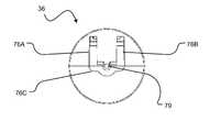
- FIG. 7is an isometric view of a nerve access needle 90 according to an example embodiment.
- a hollow shaft 92extends from a hub 94 of nerve access needle 90 .
- a catheter tube 96 and/or electrostimulator cable 97are connected to hub 94 for fluid communication with the lumen of shaft 92 .
- Hub 94comprises a sealing membrane 98 .
- a sheath assembly as described hereinmay be inserted into the lumen of needle 90 by piercing membrane 98 .
- the sensor needlemay be removed, and membrane 98 sealed. When membrane 98 is sealed, fluid from tube 96 may be delivered to the lumen of shaft 92 .
- membrane 98is a self-sealing membrane. In other embodiments, membrane 98 is sealable by the application of heat, adhesive or other means.
- hub 94has an aperture in place of membrane 98 , or a rim defining an aperture about membrane 98 .
- a stoppermay be provided for sealing the aperture after needle 90 has been positioned in the body of a patient and the sensor needle removed. In some such embodiments, the stopper may be tethered or otherwise attached to hub 94 .
- the stoppermay be shaped for sealing engagement with the aperture, and may comprise a fitting configured for engagement with a fitting about the aperture.
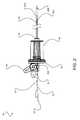
- FIG. 8is an isometric view of a position tracked instrument assembly 100 according to an example embodiment.
- a sensor cable 102 carrying a position marker(not shown) is inserted through connector base 106 into a sheath 110 .
- Sheath 110comprises a closed-ended hollow shaft 112 extending from a hub 114 .
- Connector base 116is securely engaged with hub 102 .
- Clip 108is pivotally mounted on connector base 106 for releasable locking frictional engagement with sensor cable 102 .
- a nerve access needle 120comprises a hollow shaft 122 extending from a hub 124 .
- Shaft 122 and hub 124 togetherare slightly shorter than shaft 112 so that a position marker at the end of shaft 112 will be located near or at the tip of shaft 122 .
- Hub 124comprises a sealing membrane 128 .
- Sheath 110can be inserted into needle 120 , and hub 114 positioned in abutment with hub 124 .
- the facing sides of hubs 114 and 124are configured for fitting engagement. Since shaft 122 and hub 124 together have slightly shorter than shaft 112 , placing hub 114 in abutment with hub 124 will cause shaft 112 to be coincident with shaft 122 for most of its length. It will be appreciated that shaft 112 need not extend all, or even most, of the length of shaft 112 .
- Sensor cable 102may be inserted into sheath 110 and aligned for coincidence with sheath 110 before or after sheath 110 is inserted into needle 120 .
- Connector base 106 and clip 108may be used to securely fix the position of sensor cable 102 relative to sheath 110 .
- a position marker(not shown) attached to the end of sensor cable 102 coincident with tip 112 A of sheath 110 and with tip 122 A of needle 120 .
- information from a position sensor 104may be used to position needle 120 at a desired location inside a subject's body. After needle 120 has been positioned at the desired location, sensor cable 102 and sheath 110 and may be removed, either together or in order.
- Connector base 106may be used to seal a puncture in membrane 128 .
- connector base 106comprises a fitting that is connectable to a fitting on hub 124 .
- clip 108is configured for sealing a puncture in membrane 128 when connector base 106 is connected to hub 124 .
- clip 108is configured for both frictional engagement with sensor cable 102 (in a first position) and for sealing a puncture in membrane 128 (in a second position).
- connector base 106may comprise other means for frictionally engaging sensor cable 102 and/or sealing a puncture in membrane 128 .
- Connector base 106may be used to seal an aperture of hub 124 that accommodates the insertion of sheath 110 into needle 120 .
- connector base 106comprises a fitting that is sealingly engageable to a fitting on hub 124 for sealing such an aperture.
- the aperturemay be sealed by connector base 106 independent of membrane 128 .
- clip 108is configured to seal a longitudinal aperture (not shown in FIG. 8 ) that extends through connector base 106 .
- clip 108is configured for both frictional engagement with sensor cable 102 (in a first position) and for sealing the longitudinal aperture of connector base 106 (in a second position). It will be appreciated that in alternative embodiments, connector base 106 may comprise other means for frictionally engaging sensor cable 102 and/or sealing the longitudinal aperture of connector base 106 .
- sheath 110may provide a barrier between sensor cable 102 and hollow needle 120 .
- sheath 110is disposable.
- shaft 112 of sheath 110comprises a plastic sleeve.
- connector base 106is reusable. It will be appreciated that a non-sterile connector base 106 , sensor cable 102 , and position marker (not shown) may be combined with a sheath 110 having a sterile exterior to form a sheathed position marker assembly suitable for use in a sterile medical environment.
- Appación of the inventionis not limited to taking biopsy samples.
- apparatus and methods described hereinmay be applied to positioning needles and other fine members at desired locations within a body for the introduction of a drug, such as a anesthetic, or a radioactive seed for cancer treatment or the like.
- a drugsuch as a anesthetic, or a radioactive seed for cancer treatment or the like.
- the systemmay be used to position a catheter to introduce an epidermal anesthetic.
- the systemmay also be used, for example, for inserting catheters into organs, vessels and other anatomical structures.
- the position markeris co-located with the same feature of the member being positioned that it is desired to place in a specific location.
- the featuremay be a tip of the member for example.
- the featuremay comprise an opening in a side of the member (such openings are found, for example, in some biopsy needles). Thus, certain calibration steps are avoided.
- the membermay be flexible. Even if the member flexes during insertion, the actual position of the tip or other feature of the member can be monitored.
- the sheath and any other parts of the apparatusdo not distort magnetic fields in a way that would interfere with the accuracy or reliability of position measurements. It is also desirable that the material(s) of the sheath and other parts that may contact a patient's tissues be all of: biocompatible; not damaged by commonly available sterilization protocols; and able to withstand expected mechanical forces with a suitable safety margin as is appropriate for invasive medical equipment.
- Nonmagnetic grades of stainless steelsuch as grade 304 stainless steel are available. However, even these grades tend to develop localized ferromagnetic properties when worked (as occurs, for example in making or modifying a stainless steel sheath or needle). This is a particular issue in applications in which it is desirable to deploy a position marker in an open-ended sheath or needle such that the cable or other assembly carrying the position marker must be sterile. In such cases it can be convenient to machine the tip of a stainless steel needle to serve as a biocompatible, sterile cover for a position marker and any associated cable. However, such machining can result in the stainless steel becoming magnetic in the vicinity of the machining operations.
- a position markeris received within a stainless steel cover.
- the stainless steel coveris annealed after any machining operations and before use. Annealing involves heating the stainless steel to a high temperature (e.g. 1010° C. to 1120° C.) and then rapidly cooling the stainless steel. In addition to returning the stainless steel to a non-magnetic state, annealing the mechanical properties of the stainless steel. Annealed stainless steel tends to bend more easily than non-annealed stainless steel. The enhanced bendability of annealed stainless steel would normally be a severe disadvantage in the case of a needle to be introduced into the human body.
- the position marker and its coverare received within a sheath, such as a needle, which supports the cover and provides the desired mechanical stiffness which prevents the assembly from kinking or becoming undesirably bent in normal use.
- the sheathmay, for example, comprise stainless steel in a hard state which has not been machined significantly and therefore does not require annealing to improve its magnetic properties.
- FIG. 9illustrates a position-tracked instrument assembly 200 according to an alternative embodiment.
- Assembly 200comprises a sheath 202 that receives a position sensor assembly 204 comprising a position marker 206 .
- sheath 202may comprise stainless steel in a non-annealed state and position sensor assembly 204 may comprise a cover 205 of annealed stainless steel that encloses position marker 206 and signal carrier(s) 207 (which may comprise, e.g. wires, optical fibers or the like) connected to position marker 206 .
- signal carrier(s) 207which may comprise, e.g. wires, optical fibers or the like
- sheath 202comprises a fitting 214 that engages a fitting 212 which is part of position sensor assembly 204 .
- Fitting 214may screw into threads on fitting 212 , for example, by way of external threads (not shown in FIG. 9 ) on fitting 214 .
- FIG. 10shows an assembly 220 in which fluid can be introduced through a fitting 221 .
- the fluidcan exit at the end of sheath 202 .
- Assembly 220includes a valve 222 through which position sensor assembly 204 can pass.
- Valve 222seals around position sensor assembly 204 to prevent fluid introduced by way of fitting 221 from exiting through the fitting at the proximal end of sheath 202 .
- Valve 222may, for example, comprise a duckbill valve.
- FIG. 10Ashow valve 222 in a closed state with position sensor assembly 204 removed. In this configuration,
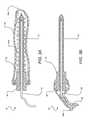
- FIG. 11shows an assembly 230 according to another alternative embodiment.
- Assembly 230is similar to assembly 100 shown in FIG. 8 with the addition of a sleeve 232 that limits how far position sensor 104 can be advanced into sheath 122 .
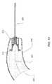
- FIG. 12illustrates one way in which position sensor assembly 204 may be used in a sterile environment.
- Cover 205is inserted through an aperture in a sterile flexible enclosure 240 .
- Enclosure 240may, for example comprise a sterile plastic sleeve.
- a sheath 202(not shown in FIG. 12 may then be slid over cover 205 .
- Enclosure 240is then held between fitting 212 of position sensor assembly 204 and a corresponding fitting (not shown in FIG. 12 ) connected to sheath 202 .
- Enclosure 240prevents signal carrier(s) 207 from coming into contact with the environment outside of enclosure 240 .
- the position markermay be located adjacent another feature of the member.
- the position markermay be located adjacent a radial opening in a vacuum biopsy needle, fire biopsy needle, or the like.
- one or more markingsare provided on a sensor cable that, when the markings are aligned with a feature of a sheath and the sheath is installed in a member, result in a position marker affixed to the sensor cable being located adjacent a particular feature of the member.
- Other example embodimentsmay be obtained, without limitation, by combining features of the disclosed embodiments.
Landscapes
- Health & Medical Sciences (AREA)
- Life Sciences & Earth Sciences (AREA)
- Surgery (AREA)
- Engineering & Computer Science (AREA)
- Veterinary Medicine (AREA)
- General Health & Medical Sciences (AREA)
- Public Health (AREA)
- Biomedical Technology (AREA)
- Heart & Thoracic Surgery (AREA)
- Medical Informatics (AREA)
- Molecular Biology (AREA)
- Animal Behavior & Ethology (AREA)
- Pathology (AREA)
- Physics & Mathematics (AREA)
- Biophysics (AREA)
- Hematology (AREA)
- Nuclear Medicine, Radiotherapy & Molecular Imaging (AREA)
- Vascular Medicine (AREA)
- Gastroenterology & Hepatology (AREA)
- Robotics (AREA)
- Surgical Instruments (AREA)
Abstract
Description
- U.S. Pat. No. 7,599,730 to Hunter et al.;
- U.S. Pat. No. 7,529,393 to Peszynski et al.;
- U.S. Pat. No. 7,366,562 to Dukesherer et al.;
- U.S. Pat. No. 7,221,972 to Jackson et al.;
- U.S. Pat. No. 7,174,202 to Bladen et al.;
- U.S. Pat. No. 6,920,347 to Simon et al.;
- U.S. Pat. No. 6,785,571 to Glossop;
- U.S. Pat. No. 6,764,449 to Lee et al.;
- U.S. Pat. No. 6,733,458 to Stein et al.;
- U.S. Pat. No. 6,317,616 to Glossop;
- U.S. Pat. No. 6,216,029 to Paltieli;
- U.S. Pat. No. 6,246,898 to Vesely et al.;
- U.S. Pat. No. 5,868,675 to Henrion et al.;
- U.S. Pat. No. 5,638,819 to Manwaring;
- U.S. Pat. No. 5,443,489 to Ben-haim;
- U.S. Pat. No. 5,211,165 to Dumoulin et al.;
- U.S. Pat. No. 5,161,536 to Vilkomerson et al.;
- U.S. Pat. No. 4,905,698 to Strohl Jr. et al.;
- U.S. Pat. No. 4,173,228 to Van Steenwyck et al.;
- U.S. Pat. No. RE41066 to Martinelli et al.;
- U.S. Pat. No. RE40852 to Martinelli et al.;
- US2009/0221908A1 to Glossop;
- US2008/0183071 to Strommer et al.
- US2007/0232882 to Glossop et al.;
- US2007/0167787 to Glossop et al.;
- US2006/0241577 to Balbierz et al.;
- US2006/0184016 to Glossop;
- US2005/0182295 to Soper et al.;
- US2005/0085793 to Glossop;
- US2004/097806 to Hunter et al.;
- US2004/0267121 to Sarvazyan et al.;
- WO 2007/067323 to Webler et al.;
- WO 99/59055 to Vesely et al.;
- WO 99/33406 to Hunter et al.;
- WO 99/27837 to Paltieli et al.;
- WO 97/03609 to Paltieli;
- WO 94/24933 to Bucholz;
- Freehand3D Ultrasound Calibration: A Review, P-W. Hsu, R. W. Prager A. H. Gee and G. M. Treece CUED/F-INFENG/TR 584, University of Cambridge Department of Engineering, December 2007
- obtaining biopsy samples;
- placing radioactive seeds for cancer treatment or the like;
- placing electrodes;
- injecting drugs at specific locations;
- inserting an epidural catheter, for example for the introduction of an anaesthetic;
- injecting epidural anaesthetic;
- positioning surgical tools for minimally-invasive surgery;
- etc.
Claims (21)
Priority Applications (1)
| Application Number | Priority Date | Filing Date | Title |
|---|---|---|---|
| US12/986,804US9486162B2 (en) | 2010-01-08 | 2011-01-07 | Spatial needle guidance system and associated methods |
Applications Claiming Priority (3)
| Application Number | Priority Date | Filing Date | Title |
|---|---|---|---|
| US29354610P | 2010-01-08 | 2010-01-08 | |
| US39378810P | 2010-10-15 | 2010-10-15 | |
| US12/986,804US9486162B2 (en) | 2010-01-08 | 2011-01-07 | Spatial needle guidance system and associated methods |
Publications (2)
| Publication Number | Publication Date |
|---|---|
| US20120016316A1 US20120016316A1 (en) | 2012-01-19 |
| US9486162B2true US9486162B2 (en) | 2016-11-08 |
Family
ID=45467501
Family Applications (1)
| Application Number | Title | Priority Date | Filing Date |
|---|---|---|---|
| US12/986,804Expired - Fee RelatedUS9486162B2 (en) | 2010-01-08 | 2011-01-07 | Spatial needle guidance system and associated methods |
Country Status (1)
| Country | Link |
|---|---|
| US (1) | US9486162B2 (en) |
Cited By (15)
| Publication number | Priority date | Publication date | Assignee | Title |
|---|---|---|---|---|
| US10235904B2 (en) | 2014-12-01 | 2019-03-19 | Truinject Corp. | Injection training tool emitting omnidirectional light |
| US10269266B2 (en) | 2017-01-23 | 2019-04-23 | Truinject Corp. | Syringe dose and position measuring apparatus |
| US10290232B2 (en) | 2014-03-13 | 2019-05-14 | Truinject Corp. | Automated detection of performance characteristics in an injection training system |
| US10441257B2 (en) | 2013-03-15 | 2019-10-15 | Cook Medical Technologies Llc | Vascular closure device suture tension limiting and indication mechanism |
| US10500340B2 (en) | 2015-10-20 | 2019-12-10 | Truinject Corp. | Injection system |
| US10643497B2 (en) | 2012-10-30 | 2020-05-05 | Truinject Corp. | System for cosmetic and therapeutic training |
| US10743942B2 (en) | 2016-02-29 | 2020-08-18 | Truinject Corp. | Cosmetic and therapeutic injection safety systems, methods, and devices |
| US10849688B2 (en) | 2016-03-02 | 2020-12-01 | Truinject Corp. | Sensory enhanced environments for injection aid and social training |
| US10896627B2 (en) | 2014-01-17 | 2021-01-19 | Truinjet Corp. | Injection site training system |
| US12004821B2 (en) | 2022-02-03 | 2024-06-11 | Medtronic Navigation, Inc. | Systems, methods, and devices for generating a hybrid image |
| US12217626B2 (en) | 2012-10-30 | 2025-02-04 | Truinject Corp. | Injection training apparatus using 3D position sensor |
| US12249099B2 (en) | 2022-02-03 | 2025-03-11 | Medtronic Navigation, Inc. | Systems, methods, and devices for reconstructing a three-dimensional representation |
| US12295797B2 (en) | 2022-02-03 | 2025-05-13 | Medtronic Navigation, Inc. | Systems, methods, and devices for providing an augmented display |
| US12415055B2 (en) | 2017-09-29 | 2025-09-16 | Terumo Kabushiki Kaisha | Catheter assembly and medical valve |
| US12426860B2 (en) | 2018-04-18 | 2025-09-30 | C.R. Bard, Inc. | Dual lumen coaxial introducer having integrated tissue marker delivery |
Families Citing this family (37)
| Publication number | Priority date | Publication date | Assignee | Title |
|---|---|---|---|---|
| US9216015B2 (en) | 2004-10-28 | 2015-12-22 | Vycor Medical, Inc. | Apparatus and methods for performing brain surgery |
| US20060287583A1 (en) | 2005-06-17 | 2006-12-21 | Pool Cover Corporation | Surgical access instruments for use with delicate tissues |
| US10524691B2 (en)* | 2007-11-26 | 2020-01-07 | C. R. Bard, Inc. | Needle assembly including an aligned magnetic element |
| ES2568225T3 (en) | 2011-09-06 | 2016-04-28 | Ezono Ag | Imaging probe and method to obtain position and / or orientation information |
| AU2013266007A1 (en) | 2012-05-21 | 2015-01-22 | The State Of Queensland Through The Department Of Health | Sampling apparatus and method |
| US9257220B2 (en) | 2013-03-05 | 2016-02-09 | Ezono Ag | Magnetization device and method |
| US9459087B2 (en) | 2013-03-05 | 2016-10-04 | Ezono Ag | Magnetic position detection system |
| GB201303917D0 (en) | 2013-03-05 | 2013-04-17 | Ezono Ag | System for image guided procedure |
| US9211110B2 (en) | 2013-03-15 | 2015-12-15 | The Regents Of The University Of Michigan | Lung ventillation measurements using ultrasound |
| EP2996587B1 (en)* | 2013-03-28 | 2022-08-24 | Koninklijke Philips N.V. | Instrument localization in guided high dose rate brachytherapy |
| WO2015095254A1 (en) | 2013-12-18 | 2015-06-25 | Stryker Corporation | Assembly for sequentially percutaneously applying an electrode and an anesthetic to tissue |
| CN103961140B (en)* | 2014-04-28 | 2016-08-24 | 广州三瑞医疗器械有限公司 | A kind of ultrasonic probe alignment sensor fixing device and method thereof |
| US10251670B2 (en) | 2014-05-09 | 2019-04-09 | Canon U.S.A., Inc. | Positioning apparatus |
| EP3142541A4 (en)* | 2014-05-13 | 2017-04-26 | Vycor Medical, Inc. | Guidance system mounts for surgical introducers |
| US20160007854A1 (en)* | 2014-07-09 | 2016-01-14 | Physical Sciences, Inc. | Apparatus and Method for Assessment of Interstitial Tissue |
| US11033297B2 (en) | 2015-11-08 | 2021-06-15 | Qin Wang | Paracentesis needle frame |
| EP3216415A1 (en)* | 2016-03-07 | 2017-09-13 | Deutsches Krebsforschungszentrum Stiftung des Öffentlichen Rechts | A system for navigated punction, biopsy or ablation comprising a needle-like instrument and a removable sensor carrier |
| US11344220B2 (en) | 2016-05-13 | 2022-05-31 | Becton, Dickinson And Company | Invasive medical device cover with magnet |
| US10327667B2 (en) | 2016-05-13 | 2019-06-25 | Becton, Dickinson And Company | Electro-magnetic needle catheter insertion system |
| US11826522B2 (en) | 2016-06-01 | 2023-11-28 | Becton, Dickinson And Company | Medical devices, systems and methods utilizing permanent magnet and magnetizable feature |
| US11116419B2 (en) | 2016-06-01 | 2021-09-14 | Becton, Dickinson And Company | Invasive medical devices including magnetic region and systems and methods |
| US20170347914A1 (en) | 2016-06-01 | 2017-12-07 | Becton, Dickinson And Company | Invasive Medical Devices Including Magnetic Region And Systems And Methods |
| US11413429B2 (en) | 2016-06-01 | 2022-08-16 | Becton, Dickinson And Company | Medical devices, systems and methods utilizing permanent magnet and magnetizable feature |
| US10032552B2 (en) | 2016-08-30 | 2018-07-24 | Becton, Dickinson And Company | Cover for tissue penetrating device with integrated magnets and magnetic shielding |
| US10376258B2 (en) | 2016-11-07 | 2019-08-13 | Vycor Medical, Inc. | Surgical introducer with guidance system receptacle |
| US10543016B2 (en) | 2016-11-07 | 2020-01-28 | Vycor Medical, Inc. | Surgical introducer with guidance system receptacle |
| US12178469B2 (en) | 2016-11-07 | 2024-12-31 | Vycor Medical Inc. | Surgical introducer with guidance system receptacle |
| US10376235B2 (en) | 2016-12-21 | 2019-08-13 | Industrial Technology Research Institute | Needle guide system and medical intervention system |
| CN106908297B (en)* | 2017-04-20 | 2023-06-20 | 首都医科大学附属北京友谊医院 | Shaping device for tissue specimens and method for shaping tissue specimens |
| WO2018208827A1 (en)* | 2017-05-08 | 2018-11-15 | Crossfire Medical Llc | Catheter systems and methods for ablating varicose veins |
| IT201800004953A1 (en)* | 2018-04-27 | 2019-10-27 | PROCEDURE AND DIAGNOSTIC SYSTEM | |
| BR112020019714A2 (en)* | 2018-04-04 | 2021-02-09 | S.I.T.-Sordina Iort Technologies S.P.A. | radiotherapy system |
| NL2022093B1 (en) | 2018-11-29 | 2020-06-26 | Sirius Medical Systems B V | The present disclosure relates to a magnetic field probe for determining a disposition of an implantable magnetic marker, a detection unit comprising the probe and a method of detecting the disposition of an implantable magnetic marker. |
| US10890918B2 (en)* | 2019-04-24 | 2021-01-12 | Innovation First, Inc. | Performance arena for robots with position location system |
| CN113456191B (en)* | 2021-07-30 | 2025-02-11 | 北京迈迪斯医疗技术有限公司 | Puncture instruments |
| CN116650081A (en)* | 2023-07-28 | 2023-08-29 | 浙江伽奈维医疗科技有限公司 | Coaxial puncture needle and puncture system based on electromagnetic navigation |
| CN118340564B (en)* | 2024-04-28 | 2025-03-14 | 磅客策(上海)智能医疗科技有限公司 | Puncture needle clamping device and puncture mechanism |
Citations (61)
| Publication number | Priority date | Publication date | Assignee | Title |
|---|---|---|---|---|
| US4173228A (en) | 1977-05-16 | 1979-11-06 | Applied Medical Devices | Catheter locating device |
| US4567896A (en) | 1984-01-20 | 1986-02-04 | Elscint, Inc. | Method and apparatus for calibrating a biopsy attachment for ultrasonic imaging apparatus |
| US4905698A (en) | 1988-09-13 | 1990-03-06 | Pharmacia Deltec Inc. | Method and apparatus for catheter location determination |
| US5078140A (en) | 1986-05-08 | 1992-01-07 | Kwoh Yik S | Imaging device - aided robotic stereotaxis system |
| US5095910A (en) | 1990-04-18 | 1992-03-17 | Advanced Technology Laboratories, Inc. | Ultrasonic imaging of biopsy needle |
| US5161536A (en) | 1991-03-22 | 1992-11-10 | Catheter Technology | Ultrasonic position indicating apparatus and methods |
| US5195526A (en)* | 1988-03-11 | 1993-03-23 | Michelson Gary K | Spinal marker needle |
| US5211165A (en) | 1991-09-03 | 1993-05-18 | General Electric Company | Tracking system to follow the position and orientation of a device with radiofrequency field gradients |
| WO1994024933A1 (en) | 1993-04-26 | 1994-11-10 | St. Louis University | Indicating the position of a surgical probe |
| US5379779A (en)* | 1993-08-16 | 1995-01-10 | Boston Scientific Corporation | Zebra exchange guidewire |
| US5425367A (en) | 1991-09-04 | 1995-06-20 | Navion Biomedical Corporation | Catheter depth, position and orientation location system |
| US5443489A (en) | 1993-07-20 | 1995-08-22 | Biosense, Inc. | Apparatus and method for ablation |
| US5515853A (en) | 1995-03-28 | 1996-05-14 | Sonometrics Corporation | Three-dimensional digital ultrasound tracking system |
| WO1997003609A1 (en) | 1995-07-16 | 1997-02-06 | Ultra-Guide Ltd. | Free-hand aiming of a needle guide |
| US5638819A (en) | 1995-08-29 | 1997-06-17 | Manwaring; Kim H. | Method and apparatus for guiding an instrument to a target |
| US5647373A (en) | 1993-11-07 | 1997-07-15 | Ultra-Guide Ltd. | Articulated needle guide for ultrasound imaging and method of using same |
| US5738632A (en)* | 1994-03-18 | 1998-04-14 | Olympus Optical Co., Ltd. | Device for use in combination with a magnetic resonance imaging apparatus |
| US5797849A (en) | 1995-03-28 | 1998-08-25 | Sonometrics Corporation | Method for carrying out a medical procedure using a three-dimensional tracking and imaging system |
| US5868675A (en) | 1989-10-05 | 1999-02-09 | Elekta Igs S.A. | Interactive system for local intervention inside a nonhumogeneous structure |
| US5879357A (en)* | 1995-10-20 | 1999-03-09 | United States Surgical Corporation | Apparatus for marking tissue location |
| WO1999027837A2 (en) | 1997-11-27 | 1999-06-10 | Ultraguide Ltd. | System and method for guiding the movements of a device to a target particularly for medical applications |
| WO1999033406A1 (en) | 1997-12-31 | 1999-07-08 | Surgical Navigation Technologies, Inc. | Wireless probe system for use with a stereotactic surgical device |
| WO1999058055A1 (en) | 1998-05-08 | 1999-11-18 | Sonometrics Corporation | A method for carrying out a medical procedure using a three-dimensional tracking and imaging system |
| WO1999059055A1 (en) | 1998-05-08 | 1999-11-18 | Infineon Technologies Ag | Method for analog-digital conversion of analog signals and corresponding analog-digital converter array |
| US6317616B1 (en) | 1999-09-15 | 2001-11-13 | Neil David Glossop | Method and system to facilitate image guided surgery |
| US20020188196A1 (en)* | 1999-02-02 | 2002-12-12 | Burbank Fred H. | Cavity-filling biopsy site markers |
| US6524247B2 (en) | 2001-05-15 | 2003-02-25 | U-Systems, Inc. | Method and system for ultrasound imaging of a biopsy needle |
| US6574497B1 (en)* | 2000-12-22 | 2003-06-03 | Advanced Cardiovascular Systems, Inc. | MRI medical device markers utilizing fluorine-19 |
| US6628977B2 (en) | 1999-12-28 | 2003-09-30 | Siemens Aktiengesellschaft | Method and system for visualizing an object |
| WO2004019799A2 (en) | 2002-08-29 | 2004-03-11 | Computerized Medical Systems, Inc. | Methods and systems for localizing of a medical imaging probe and of a biopsy needle |
| WO2004023103A2 (en) | 2002-09-09 | 2004-03-18 | Z-Kat, Inc. | Image guided interventional method and apparatus |
| US6733458B1 (en) | 2001-09-25 | 2004-05-11 | Acuson Corporation | Diagnostic medical ultrasound systems and methods using image based freehand needle guidance |
| US20040097806A1 (en) | 2002-11-19 | 2004-05-20 | Mark Hunter | Navigation system for cardiac therapies |
| US6764449B2 (en) | 2001-12-31 | 2004-07-20 | Medison Co., Ltd. | Method and apparatus for enabling a biopsy needle to be observed |
| US6785571B2 (en) | 2001-03-30 | 2004-08-31 | Neil David Glossop | Device and method for registering a position sensor in an anatomical body |
| US20040267121A1 (en) | 2003-06-12 | 2004-12-30 | Sarvazyan Armen P. | Device and method for biopsy guidance using a tactile breast imager |
| US6875179B2 (en) | 2002-06-17 | 2005-04-05 | Board Of Trustees Of The University Of Arkansas | Ultrasonic guided catheter deployment system |
| US6920347B2 (en) | 2000-04-07 | 2005-07-19 | Surgical Navigation Technologies, Inc. | Trajectory storage apparatus and method for surgical navigation systems |
| US20050182295A1 (en) | 2003-12-12 | 2005-08-18 | University Of Washington | Catheterscope 3D guidance and interface system |
| US20060009714A1 (en)* | 2004-07-09 | 2006-01-12 | Yoshio Higaki | Blood collection needle |
| US20060184016A1 (en) | 2005-01-18 | 2006-08-17 | Glossop Neil D | Method and apparatus for guiding an instrument to a target in the lung |
| US20060241577A1 (en) | 2000-03-31 | 2006-10-26 | Rita Medical Systems, Inc. | Tissue biopsy and treatment apparatus and method |
| US7142905B2 (en) | 2000-12-28 | 2006-11-28 | Guided Therapy Systems, Inc. | Visual imaging system for ultrasonic probe |
| US7174202B2 (en) | 1992-08-14 | 2007-02-06 | British Telecommunications | Medical navigation apparatus |
| US7221972B2 (en) | 2003-08-29 | 2007-05-22 | Siemens Medical Solutions Usa, Inc. | Ultrasound system with protocol-driven user interface |
| WO2007067323A2 (en) | 2005-12-02 | 2007-06-14 | Abbott Cardiovascular Systems Inc. | Image-guidance in medical image processing |
| US7244234B2 (en) | 2003-11-11 | 2007-07-17 | Soma Development Llc | Ultrasound guided probe device and method of using same |
| US20070167787A1 (en) | 2005-06-21 | 2007-07-19 | Glossop Neil D | Device and method for a trackable ultrasound |
| US20070232882A1 (en) | 2006-03-31 | 2007-10-04 | Glossop Neil D | System, Methods, and Instrumentation for Image Guided Prostate Treatment |
| US7366562B2 (en) | 2003-10-17 | 2008-04-29 | Medtronic Navigation, Inc. | Method and apparatus for surgical navigation |
| US20080132911A1 (en) | 2006-11-27 | 2008-06-05 | Mediguide Ltd. | System and method for navigating a surgical needle toward an organ of the body of a patient |
| US20080183071A1 (en) | 2007-01-10 | 2008-07-31 | Mediguide Lit. | System and method for superimposing a representation of the tip of a catheter on an image acquired by a moving imager |
| US20090093691A1 (en)* | 2006-02-09 | 2009-04-09 | Konklijke Philips Electronics N.V. | Device for monitoring the status of a patient and treatment based thereupon |
| WO2009049082A1 (en) | 2007-10-12 | 2009-04-16 | Gynesonics, Inc. | Methods and systems for controlled deployment of needles in tissue |
| US7529393B2 (en) | 2003-03-27 | 2009-05-05 | Koninklijke Philips Electronics, N.V. | Guidance of invasive medical devices by wide view three dimensional ultrasonic imaging |
| USRE40852E1 (en) | 1995-06-14 | 2009-07-14 | Medtronic Navigation, Inc. | Method and system for navigating a catheter probe |
| US20090221908A1 (en) | 2008-03-01 | 2009-09-03 | Neil David Glossop | System and Method for Alignment of Instrumentation in Image-Guided Intervention |
| US20090299176A1 (en)* | 2004-12-22 | 2009-12-03 | Koninklijke Philips Electronics, N.V. | Marker for position determination with a magnetic method |
| WO2009153723A1 (en) | 2008-06-20 | 2009-12-23 | Koninklijke Philips Electronics, N.V. | Method and system for performing biopsies |
| US20100041990A1 (en)* | 2008-08-13 | 2010-02-18 | John Schlitt | Needle Guides for Catheter Delivery |
| US20100298736A1 (en)* | 2009-05-15 | 2010-11-25 | Mayo Foundation For Medical Education And Research | Biopsy Needle Assemblies |
- 2011
- 2011-01-07USUS12/986,804patent/US9486162B2/ennot_activeExpired - Fee Related
Patent Citations (69)
| Publication number | Priority date | Publication date | Assignee | Title |
|---|---|---|---|---|
| US4173228A (en) | 1977-05-16 | 1979-11-06 | Applied Medical Devices | Catheter locating device |
| US4567896A (en) | 1984-01-20 | 1986-02-04 | Elscint, Inc. | Method and apparatus for calibrating a biopsy attachment for ultrasonic imaging apparatus |
| US5078140A (en) | 1986-05-08 | 1992-01-07 | Kwoh Yik S | Imaging device - aided robotic stereotaxis system |
| US5195526A (en)* | 1988-03-11 | 1993-03-23 | Michelson Gary K | Spinal marker needle |
| US4905698A (en) | 1988-09-13 | 1990-03-06 | Pharmacia Deltec Inc. | Method and apparatus for catheter location determination |
| US4905698B1 (en) | 1988-09-13 | 1991-10-01 | Pharmacia Deltec Inc | |
| US5868675A (en) | 1989-10-05 | 1999-02-09 | Elekta Igs S.A. | Interactive system for local intervention inside a nonhumogeneous structure |
| US5095910A (en) | 1990-04-18 | 1992-03-17 | Advanced Technology Laboratories, Inc. | Ultrasonic imaging of biopsy needle |
| US5161536A (en) | 1991-03-22 | 1992-11-10 | Catheter Technology | Ultrasonic position indicating apparatus and methods |
| US5211165A (en) | 1991-09-03 | 1993-05-18 | General Electric Company | Tracking system to follow the position and orientation of a device with radiofrequency field gradients |
| US5425367A (en) | 1991-09-04 | 1995-06-20 | Navion Biomedical Corporation | Catheter depth, position and orientation location system |
| US7174202B2 (en) | 1992-08-14 | 2007-02-06 | British Telecommunications | Medical navigation apparatus |
| WO1994024933A1 (en) | 1993-04-26 | 1994-11-10 | St. Louis University | Indicating the position of a surgical probe |
| US5443489A (en) | 1993-07-20 | 1995-08-22 | Biosense, Inc. | Apparatus and method for ablation |
| US5379779A (en)* | 1993-08-16 | 1995-01-10 | Boston Scientific Corporation | Zebra exchange guidewire |
| US5647373A (en) | 1993-11-07 | 1997-07-15 | Ultra-Guide Ltd. | Articulated needle guide for ultrasound imaging and method of using same |
| US5738632A (en)* | 1994-03-18 | 1998-04-14 | Olympus Optical Co., Ltd. | Device for use in combination with a magnetic resonance imaging apparatus |
| US5515853A (en) | 1995-03-28 | 1996-05-14 | Sonometrics Corporation | Three-dimensional digital ultrasound tracking system |
| US5797849A (en) | 1995-03-28 | 1998-08-25 | Sonometrics Corporation | Method for carrying out a medical procedure using a three-dimensional tracking and imaging system |
| WO1996031753A2 (en) | 1995-03-28 | 1996-10-10 | Sonometrics Corporation | Three-dimensional digital ultrasound tracking system |
| US6246898B1 (en) | 1995-03-28 | 2001-06-12 | Sonometrics Corporation | Method for carrying out a medical procedure using a three-dimensional tracking and imaging system |
| USRE40852E1 (en) | 1995-06-14 | 2009-07-14 | Medtronic Navigation, Inc. | Method and system for navigating a catheter probe |
| USRE41066E1 (en) | 1995-06-14 | 2009-12-29 | Metronic Navigation, Inc. | Method and system for navigating a catheter probe |
| US6216029B1 (en) | 1995-07-16 | 2001-04-10 | Ultraguide Ltd. | Free-hand aiming of a needle guide |
| WO1997003609A1 (en) | 1995-07-16 | 1997-02-06 | Ultra-Guide Ltd. | Free-hand aiming of a needle guide |
| US5638819A (en) | 1995-08-29 | 1997-06-17 | Manwaring; Kim H. | Method and apparatus for guiding an instrument to a target |
| US5879357A (en)* | 1995-10-20 | 1999-03-09 | United States Surgical Corporation | Apparatus for marking tissue location |
| WO1999027837A2 (en) | 1997-11-27 | 1999-06-10 | Ultraguide Ltd. | System and method for guiding the movements of a device to a target particularly for medical applications |
| WO1999033406A1 (en) | 1997-12-31 | 1999-07-08 | Surgical Navigation Technologies, Inc. | Wireless probe system for use with a stereotactic surgical device |
| EP1076512A1 (en) | 1998-05-08 | 2001-02-21 | Sonometrics Corporation | A method for carrying out a medical procedure using a three-dimensional tracking and imaging system |
| WO1999059055A1 (en) | 1998-05-08 | 1999-11-18 | Infineon Technologies Ag | Method for analog-digital conversion of analog signals and corresponding analog-digital converter array |
| WO1999058055A1 (en) | 1998-05-08 | 1999-11-18 | Sonometrics Corporation | A method for carrying out a medical procedure using a three-dimensional tracking and imaging system |
| US20020188196A1 (en)* | 1999-02-02 | 2002-12-12 | Burbank Fred H. | Cavity-filling biopsy site markers |
| US6317616B1 (en) | 1999-09-15 | 2001-11-13 | Neil David Glossop | Method and system to facilitate image guided surgery |
| US6628977B2 (en) | 1999-12-28 | 2003-09-30 | Siemens Aktiengesellschaft | Method and system for visualizing an object |
| US20060241577A1 (en) | 2000-03-31 | 2006-10-26 | Rita Medical Systems, Inc. | Tissue biopsy and treatment apparatus and method |
| US6920347B2 (en) | 2000-04-07 | 2005-07-19 | Surgical Navigation Technologies, Inc. | Trajectory storage apparatus and method for surgical navigation systems |
| US6574497B1 (en)* | 2000-12-22 | 2003-06-03 | Advanced Cardiovascular Systems, Inc. | MRI medical device markers utilizing fluorine-19 |
| US7142905B2 (en) | 2000-12-28 | 2006-11-28 | Guided Therapy Systems, Inc. | Visual imaging system for ultrasonic probe |
| US6785571B2 (en) | 2001-03-30 | 2004-08-31 | Neil David Glossop | Device and method for registering a position sensor in an anatomical body |
| US20050085793A1 (en) | 2001-03-30 | 2005-04-21 | Glossop Neil D. | Device and method for registering a position sensor in an anatomical body |
| US6524247B2 (en) | 2001-05-15 | 2003-02-25 | U-Systems, Inc. | Method and system for ultrasound imaging of a biopsy needle |
| US6733458B1 (en) | 2001-09-25 | 2004-05-11 | Acuson Corporation | Diagnostic medical ultrasound systems and methods using image based freehand needle guidance |
| US6764449B2 (en) | 2001-12-31 | 2004-07-20 | Medison Co., Ltd. | Method and apparatus for enabling a biopsy needle to be observed |
| US6875179B2 (en) | 2002-06-17 | 2005-04-05 | Board Of Trustees Of The University Of Arkansas | Ultrasonic guided catheter deployment system |
| WO2004019799A2 (en) | 2002-08-29 | 2004-03-11 | Computerized Medical Systems, Inc. | Methods and systems for localizing of a medical imaging probe and of a biopsy needle |
| WO2004023103A2 (en) | 2002-09-09 | 2004-03-18 | Z-Kat, Inc. | Image guided interventional method and apparatus |
| US20040097806A1 (en) | 2002-11-19 | 2004-05-20 | Mark Hunter | Navigation system for cardiac therapies |
| US7599730B2 (en) | 2002-11-19 | 2009-10-06 | Medtronic Navigation, Inc. | Navigation system for cardiac therapies |
| US7529393B2 (en) | 2003-03-27 | 2009-05-05 | Koninklijke Philips Electronics, N.V. | Guidance of invasive medical devices by wide view three dimensional ultrasonic imaging |
| US20040267121A1 (en) | 2003-06-12 | 2004-12-30 | Sarvazyan Armen P. | Device and method for biopsy guidance using a tactile breast imager |
| US7221972B2 (en) | 2003-08-29 | 2007-05-22 | Siemens Medical Solutions Usa, Inc. | Ultrasound system with protocol-driven user interface |
| US7366562B2 (en) | 2003-10-17 | 2008-04-29 | Medtronic Navigation, Inc. | Method and apparatus for surgical navigation |
| US7244234B2 (en) | 2003-11-11 | 2007-07-17 | Soma Development Llc | Ultrasound guided probe device and method of using same |
| US20050182295A1 (en) | 2003-12-12 | 2005-08-18 | University Of Washington | Catheterscope 3D guidance and interface system |
| US20060009714A1 (en)* | 2004-07-09 | 2006-01-12 | Yoshio Higaki | Blood collection needle |
| US20090299176A1 (en)* | 2004-12-22 | 2009-12-03 | Koninklijke Philips Electronics, N.V. | Marker for position determination with a magnetic method |
| US20060184016A1 (en) | 2005-01-18 | 2006-08-17 | Glossop Neil D | Method and apparatus for guiding an instrument to a target in the lung |
| US20070167787A1 (en) | 2005-06-21 | 2007-07-19 | Glossop Neil D | Device and method for a trackable ultrasound |
| WO2007067323A2 (en) | 2005-12-02 | 2007-06-14 | Abbott Cardiovascular Systems Inc. | Image-guidance in medical image processing |
| US20090093691A1 (en)* | 2006-02-09 | 2009-04-09 | Konklijke Philips Electronics N.V. | Device for monitoring the status of a patient and treatment based thereupon |
| US20070232882A1 (en) | 2006-03-31 | 2007-10-04 | Glossop Neil D | System, Methods, and Instrumentation for Image Guided Prostate Treatment |
| US20080132911A1 (en) | 2006-11-27 | 2008-06-05 | Mediguide Ltd. | System and method for navigating a surgical needle toward an organ of the body of a patient |
| US20080183071A1 (en) | 2007-01-10 | 2008-07-31 | Mediguide Lit. | System and method for superimposing a representation of the tip of a catheter on an image acquired by a moving imager |
| WO2009049082A1 (en) | 2007-10-12 | 2009-04-16 | Gynesonics, Inc. | Methods and systems for controlled deployment of needles in tissue |
| US20090221908A1 (en) | 2008-03-01 | 2009-09-03 | Neil David Glossop | System and Method for Alignment of Instrumentation in Image-Guided Intervention |
| WO2009153723A1 (en) | 2008-06-20 | 2009-12-23 | Koninklijke Philips Electronics, N.V. | Method and system for performing biopsies |
| US20100041990A1 (en)* | 2008-08-13 | 2010-02-18 | John Schlitt | Needle Guides for Catheter Delivery |
| US20100298736A1 (en)* | 2009-05-15 | 2010-11-25 | Mayo Foundation For Medical Education And Research | Biopsy Needle Assemblies |
Non-Patent Citations (1)
| Title |
|---|
| Hsu, P-W et al., "Freehand 3D Ultrasound Calibration: A Review", CUED/F-INFENG/TR 584, University of Cambridge Department of Engineering, Dec. 2007. |
Cited By (23)
| Publication number | Priority date | Publication date | Assignee | Title |
|---|---|---|---|---|
| US10902746B2 (en) | 2012-10-30 | 2021-01-26 | Truinject Corp. | System for cosmetic and therapeutic training |
| US12217626B2 (en) | 2012-10-30 | 2025-02-04 | Truinject Corp. | Injection training apparatus using 3D position sensor |
| US10643497B2 (en) | 2012-10-30 | 2020-05-05 | Truinject Corp. | System for cosmetic and therapeutic training |
| US11854426B2 (en) | 2012-10-30 | 2023-12-26 | Truinject Corp. | System for cosmetic and therapeutic training |
| US11403964B2 (en) | 2012-10-30 | 2022-08-02 | Truinject Corp. | System for cosmetic and therapeutic training |
| US10441257B2 (en) | 2013-03-15 | 2019-10-15 | Cook Medical Technologies Llc | Vascular closure device suture tension limiting and indication mechanism |
| US10896627B2 (en) | 2014-01-17 | 2021-01-19 | Truinjet Corp. | Injection site training system |
| US10290232B2 (en) | 2014-03-13 | 2019-05-14 | Truinject Corp. | Automated detection of performance characteristics in an injection training system |
| US10290231B2 (en) | 2014-03-13 | 2019-05-14 | Truinject Corp. | Automated detection of performance characteristics in an injection training system |
| US10235904B2 (en) | 2014-12-01 | 2019-03-19 | Truinject Corp. | Injection training tool emitting omnidirectional light |
| US10500340B2 (en) | 2015-10-20 | 2019-12-10 | Truinject Corp. | Injection system |
| US12070581B2 (en) | 2015-10-20 | 2024-08-27 | Truinject Corp. | Injection system |
| US10743942B2 (en) | 2016-02-29 | 2020-08-18 | Truinject Corp. | Cosmetic and therapeutic injection safety systems, methods, and devices |
| US10849688B2 (en) | 2016-03-02 | 2020-12-01 | Truinject Corp. | Sensory enhanced environments for injection aid and social training |
| US11730543B2 (en) | 2016-03-02 | 2023-08-22 | Truinject Corp. | Sensory enhanced environments for injection aid and social training |
| US11710424B2 (en) | 2017-01-23 | 2023-07-25 | Truinject Corp. | Syringe dose and position measuring apparatus |
| US10269266B2 (en) | 2017-01-23 | 2019-04-23 | Truinject Corp. | Syringe dose and position measuring apparatus |
| US12350472B2 (en) | 2017-01-23 | 2025-07-08 | Truinject Corp. | Syringe dose and position measuring apparatus |
| US12415055B2 (en) | 2017-09-29 | 2025-09-16 | Terumo Kabushiki Kaisha | Catheter assembly and medical valve |
| US12426860B2 (en) | 2018-04-18 | 2025-09-30 | C.R. Bard, Inc. | Dual lumen coaxial introducer having integrated tissue marker delivery |
| US12004821B2 (en) | 2022-02-03 | 2024-06-11 | Medtronic Navigation, Inc. | Systems, methods, and devices for generating a hybrid image |
| US12249099B2 (en) | 2022-02-03 | 2025-03-11 | Medtronic Navigation, Inc. | Systems, methods, and devices for reconstructing a three-dimensional representation |
| US12295797B2 (en) | 2022-02-03 | 2025-05-13 | Medtronic Navigation, Inc. | Systems, methods, and devices for providing an augmented display |
Also Published As
| Publication number | Publication date |
|---|---|
| US20120016316A1 (en) | 2012-01-19 |
Similar Documents
| Publication | Publication Date | Title |
|---|---|---|
| US9486162B2 (en) | Spatial needle guidance system and associated methods | |
| JP6703590B2 (en) | Needle guidance system for use with ultrasonic devices | |
| EP2364120B1 (en) | Em tracking systems for use with ultrasound and other imaging modalities | |
| EP3685774B1 (en) | Medical device having visible puncture apparatus | |
| CN107184272B (en) | Composite curve type navigation catheter | |
| EP1958588A2 (en) | Medical guide for guiding a medical instrument | |
| US10555719B2 (en) | Ultrasound assisted needle puncture mechanism | |
| US11311311B2 (en) | Devices and methods for guiding a surgical instrument | |
| US9492638B2 (en) | Implements for identifying sheath migration | |
| US8849382B2 (en) | Apparatus and display methods relating to intravascular placement of a catheter | |
| EP2337491B1 (en) | Apparatus and display methods relating to intravascular placement of a catheter | |
| EP2842487A1 (en) | Locatable catheter | |
| US20140188133A1 (en) | Iconic Representations for Guidance of an Indwelling Medical Device | |
| US20110015533A1 (en) | Stylets for use with apparatus for intravascular placement of a catheter | |
| KR20200047537A (en) | Detection system and method for automatic detection of surgical instruments | |
| CN116650081A (en) | Coaxial puncture needle and puncture system based on electromagnetic navigation | |
| EP2080478A1 (en) | Device for guiding an invasive medical instrument | |
| WO2015060711A2 (en) | A universal neurosurgical probe | |
| US20220370050A1 (en) | Medical needle guidance system | |
| EP3426178B1 (en) | A system for navigated punction, biopsy or ablation comprising a needle-like instrument and a removable sensor carrier |
Legal Events
| Date | Code | Title | Description |
|---|---|---|---|
| AS | Assignment | Owner name:ULTRASONIX MEDICAL CORPORATION, CANADA Free format text:ASSIGNMENT OF ASSIGNORS INTEREST;ASSIGNORS:ZHUANG, BO;PELISSIER, LAURENT;ANTONIO, ALEX;SIGNING DATES FROM 20110111 TO 20110120;REEL/FRAME:025734/0832 | |
| ZAAA | Notice of allowance and fees due | Free format text:ORIGINAL CODE: NOA | |
| ZAAB | Notice of allowance mailed | Free format text:ORIGINAL CODE: MN/=. | |
| STCF | Information on status: patent grant | Free format text:PATENTED CASE | |
| FEPP | Fee payment procedure | Free format text:PAYOR NUMBER ASSIGNED (ORIGINAL EVENT CODE: ASPN); ENTITY STATUS OF PATENT OWNER: LARGE ENTITY | |
| AS | Assignment | Owner name:ANALOGIC CANADA CORPORATION, CANADA Free format text:MERGER;ASSIGNOR:ULTRASONIX MEDICAL CORPORATION;REEL/FRAME:043673/0948 Effective date:20160801 | |
| AS | Assignment | Owner name:BK MEDICAL HOLDING COMPANY, INC., MASSACHUSETTS Free format text:MERGER;ASSIGNORS:ANALOGIC CORPORATION;ANALOGIC CANADA CORP.;REEL/FRAME:047135/0561 Effective date:20180926 | |
| AS | Assignment | Owner name:MIDCAP FINANCIAL TRUST, MARYLAND Free format text:SECURITY INTEREST;ASSIGNOR:BK MEDICAL HOLDING COMPANY, INC.;REEL/FRAME:051569/0525 Effective date:20200121 | |
| MAFP | Maintenance fee payment | Free format text:PAYMENT OF MAINTENANCE FEE, 4TH YEAR, LARGE ENTITY (ORIGINAL EVENT CODE: M1551); ENTITY STATUS OF PATENT OWNER: LARGE ENTITY Year of fee payment:4 | |
| AS | Assignment | Owner name:BK MEDICAL HOLDING COMPANY, INC., MASSACHUSETTS Free format text:RELEASE BY SECURED PARTY;ASSIGNOR:MIDCAP FINANCIAL TRUST;REEL/FRAME:058456/0749 Effective date:20211221 | |
| LAPS | Lapse for failure to pay maintenance fees | Free format text:PATENT EXPIRED FOR FAILURE TO PAY MAINTENANCE FEES (ORIGINAL EVENT CODE: EXP.); ENTITY STATUS OF PATENT OWNER: LARGE ENTITY | |
| STCH | Information on status: patent discontinuation | Free format text:PATENT EXPIRED DUE TO NONPAYMENT OF MAINTENANCE FEES UNDER 37 CFR 1.362 | |
| FP | Lapsed due to failure to pay maintenance fee | Effective date:20241108 |