US9484011B2 - Echo modulation methods and system - Google Patents
Echo modulation methods and systemDownload PDFInfo
- Publication number
- US9484011B2 US9484011B2US14/045,318US201314045318AUS9484011B2US 9484011 B2US9484011 B2US 9484011B2US 201314045318 AUS201314045318 AUS 201314045318AUS 9484011 B2US9484011 B2US 9484011B2
- Authority
- US
- United States
- Prior art keywords
- values
- samples
- cepstrum
- audio signal
- echo
- Prior art date
- Legal status (The legal status is an assumption and is not a legal conclusion. Google has not performed a legal analysis and makes no representation as to the accuracy of the status listed.)
- Active, expires
Links
- 238000000034methodMethods0.000titleclaimsabstractdescription95
- 230000005236sound signalEffects0.000claimsabstractdescription91
- 230000001131transforming effectEffects0.000claimsdescription5
- 230000001737promoting effectEffects0.000claimsdescription3
- 230000000737periodic effectEffects0.000abstractdescription6
- 238000002592echocardiographyMethods0.000description47
- 238000012937correctionMethods0.000description30
- 230000006870functionEffects0.000description20
- 238000009826distributionMethods0.000description16
- 238000001514detection methodMethods0.000description15
- 238000010586diagramMethods0.000description13
- 230000004075alterationEffects0.000description7
- 230000008569processEffects0.000description6
- 238000012545processingMethods0.000description6
- 230000005540biological transmissionEffects0.000description5
- 230000001934delayEffects0.000description5
- 230000015654memoryEffects0.000description5
- 239000000654additiveSubstances0.000description4
- 230000000996additive effectEffects0.000description4
- 238000004364calculation methodMethods0.000description3
- 239000004973liquid crystal related substanceSubstances0.000description2
- 230000001413cellular effectEffects0.000description1
- 238000006243chemical reactionMethods0.000description1
- 230000000694effectsEffects0.000description1
- 230000007274generation of a signal involved in cell-cell signalingEffects0.000description1
- 238000004519manufacturing processMethods0.000description1
- 238000012986modificationMethods0.000description1
- 230000004048modificationEffects0.000description1
- 230000003287optical effectEffects0.000description1
- 238000012797qualificationMethods0.000description1
- 230000003068static effectEffects0.000description1
- 238000003860storageMethods0.000description1
- 230000007704transitionEffects0.000description1
Images


Classifications
- G—PHYSICS
- G10—MUSICAL INSTRUMENTS; ACOUSTICS
- G10K—SOUND-PRODUCING DEVICES; METHODS OR DEVICES FOR PROTECTING AGAINST, OR FOR DAMPING, NOISE OR OTHER ACOUSTIC WAVES IN GENERAL; ACOUSTICS NOT OTHERWISE PROVIDED FOR
- G10K15/00—Acoustics not otherwise provided for
- G10K15/08—Arrangements for producing a reverberation or echo sound
- G—PHYSICS
- G10—MUSICAL INSTRUMENTS; ACOUSTICS
- G10L—SPEECH ANALYSIS TECHNIQUES OR SPEECH SYNTHESIS; SPEECH RECOGNITION; SPEECH OR VOICE PROCESSING TECHNIQUES; SPEECH OR AUDIO CODING OR DECODING
- G10L19/00—Speech or audio signals analysis-synthesis techniques for redundancy reduction, e.g. in vocoders; Coding or decoding of speech or audio signals, using source filter models or psychoacoustic analysis
- G10L19/02—Speech or audio signals analysis-synthesis techniques for redundancy reduction, e.g. in vocoders; Coding or decoding of speech or audio signals, using source filter models or psychoacoustic analysis using spectral analysis, e.g. transform vocoders or subband vocoders
- G10L19/022—Blocking, i.e. grouping of samples in time; Choice of analysis windows; Overlap factoring
- G—PHYSICS
- G10—MUSICAL INSTRUMENTS; ACOUSTICS
- G10L—SPEECH ANALYSIS TECHNIQUES OR SPEECH SYNTHESIS; SPEECH RECOGNITION; SPEECH OR VOICE PROCESSING TECHNIQUES; SPEECH OR AUDIO CODING OR DECODING
- G10L21/00—Speech or voice signal processing techniques to produce another audible or non-audible signal, e.g. visual or tactile, in order to modify its quality or its intelligibility
- G10L21/02—Speech enhancement, e.g. noise reduction or echo cancellation
- G10L21/0208—Noise filtering
- G10L2021/02082—Noise filtering the noise being echo, reverberation of the speech
- H—ELECTRICITY
- H04—ELECTRIC COMMUNICATION TECHNIQUE
- H04M—TELEPHONIC COMMUNICATION
- H04M9/00—Arrangements for interconnection not involving centralised switching
- H04M9/08—Two-way loud-speaking telephone systems with means for conditioning the signal, e.g. for suppressing echoes for one or both directions of traffic
- H04M9/082—Two-way loud-speaking telephone systems with means for conditioning the signal, e.g. for suppressing echoes for one or both directions of traffic using echo cancellers
Definitions
- the present applicationrelates generally to the technical field of signal processing.
- the present applicationmay relate to a method and system for echo modulation.
- Content signals including video and audiohave been encoded with data for a variety of different uses.
- the encoded datamay be encoded within the audio channel, the video channel, or both the audio and video channel of the content signal.
- encoding data into the content signalmay alter the content signal in a way where the encoding is perceptible when the encoded content signal is reproduced.
- FIG. 1is a block diagram of an example encoding system, according to an example embodiment
- FIG. 2is a block diagram of an example decoding system, according to an example embodiment
- FIG. 3is a block diagram of an example audio encoder that may be deployed within the encoding system of FIG. 1 , according to an example embodiment
- FIG. 4is a block diagram of an example detection device that may be deployed within the decoding system of FIG. 2 , according to an example embodiment
- FIG. 5is a block diagram of an example audio encoding subsystem that may be deployed within the audio encoder of FIG. 3 , according to an example embodiment
- FIG. 6is a block diagram of an example audio decoding subsystem that may be deployed within the detection device of FIG. 4 , according to an example embodiment
- FIG. 7Ais a block diagram of a flowchart illustrating method for audio encoding, according to an example embodiment
- FIG. 7Bis a block diagram of a flowchart illustrating method for bit selection, according to an example embodiment
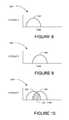
- FIGS. 8-10are illustrations of windows, according to example embodiments.
- FIG. 11is an illustration of the application of a periodic boundary condition, according to an example embodiment
- FIGS. 12-16are illustrations of charts, according to example embodiments.
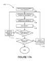
- FIGS. 17A and Bare block diagrams of flowcharts illustrating methods for audio decoding, according to example embodiments.
- FIGS. 18 and 19are illustrations, according to example embodiments.
- FIG. 20is a block diagram of a flowchart illustrating a method for audio decoding, according to an example embodiment
- FIG. 21is a block diagram of a flowchart illustrating method for calculating cepstrum values, according to an example embodiment.
- FIG. 22is a block diagram of a machine in the example form of a computer system within which a set of instructions for causing the machine to perform any one or more of the methodologies discussed herein may be executed.
- Example methods and systems for echo modulationare described.
- numerous specific detailsare set forth in order to provide a thorough understanding of example embodiments. It will be evident, however, to one of ordinary skill in the art that embodiments of the inventive subject matter may be practiced without these specific details.
- a series of bits (1's and 0's) in a digital audio signalare encoded by adding echoes to the audio signal so that, in some embodiments, the encoding is imperceptible.
- the decoding of the modulated audio signalmay recover the encoded bits.
- An error correction methodmay be used in conjunction with the encoding method to handle the forms of noise encountered in real applications.
- the echo modulationis based on Bender's echo hiding technique.
- One example applicationis for embedding an information bit sequence into a multichannel audio signal.
- the embeddingmay be perceptually transparent.
- the watermarked audio signalmay then be compressed and transmitted to a stereo system or a home theater.
- a microphone in the same roomcaptures the sound wave, which is then digitized and processed for extracting the embedded bit sequence.
- Another embodimentmay involve decoding a signal that is decoded after captured by a sound card.
- the original audio signalmay be a portion of a video signal, may be combined with other data, or may only include audio.
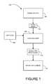
- FIG. 1illustrates an example encoding system 100 .
- the encoding system 100is an example platform in which one or more embodiments of an encoding method may be used. However, the encoding may also be performed within other platforms.
- An audio signal 104may be provided from a signal source 102 to an audio encoder 106 in the encoding system 100 .
- the audio signal 104is described by a set of numerical values samples.
- the audio signal 104is in a digital format.
- the audio signalis in an analog format. In such embodiments, the analog signal may be digitized prior to further processing (e.g., encoding or decoding).
- the audio signal 104may be a portion of a video signal that includes standard definition (SD) and/or high definition (HD) content signals in NTSC (National Television Standards Committee), PAL (Phase Alternation Line), SECAM (Systeme Electronique Couleur Avec Memoire), a MPEG (Moving Picture Experts Group) signal, a sequence of JPEGs (Joint Photographic Experts Group), a sequence of bitmaps, or other signal formats that transport of a sequence of images.
- the audio signal 104may be a single channel audio signal, a two channel audio signal, or a greater than two channel audio signal (e.g., 5.1 surround sound or 7.1 surround sound).
- the form of the audio signal 104may be modified to enable implementations involving various formats and qualities.
- the signal source 102is a unit that is capable of providing and/or reproducing audio electrically in the form of the audio signal 104 .
- the signal source 102may be, by way of examples, a digital audio tape (DAT) player with a DAT, a tape player with a cassette tape, a compact disc (CD) player with a CD, or the like.
- Examples of the signal source 102 when the audio signal 104 is a part of a video signalincludes a professional grade video tape player with a video tape, a camcorder, a video file server, a computer with an output port, a digital versatile disc (DVD) player with a DVD disc, and the like.
- An operator 108may interact with the audio encoder 106 to control operation of the audio encoder 106 to encode echoes in the audio signal 104 , thereby producing a modulated audio signal 112 that may be provided to a broadcast source 114 .
- the operator 108may include a person that interacts with the audio encoder 106 through the use of a computer or other electronic control device.
- the operator 108may consist entirely of hardware, firmware, and/or software, or other electronic control device that directs operation of the audio encoder 106 in an automated manner.
- the modulated audio signal 112may be provided to the broadcast source 114 for distribution and/or transmission to an end-user that may listen to the audio content associated with the modulated audio signal 112 .
- the broadcast source 114may deliver the modulated audio signal 112 to one or more listeners in formats including analog and/or digital audio or video by storage medium such as DVD, tapes, and other fixed medium and/or by transmission sources such as television broadcast stations, cable, satellite, wireless and Internet sources that broadcast or otherwise transmit content.
- the broadcast source 114may be a computer system.
- the modulated audio signal 112is encoded at the broadcast source 114 prior to delivering the modulated audio signal 112 to the one or more viewers.
- additional encodinge.g., MPEG encoding
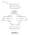
- FIG. 2illustrates an example decoding system 200 .
- the decoding system 200is an example platform in which one or more embodiments of a decoding method may be used. However, the decoding may also be performed within other platforms.
- the detection system 200may send the modulated content signal 112 from the broadcast source 114 (see FIG. 1 ) to an audio receiver 202 and/or a display device 204 .
- the audio receiver 202may receive an audio transmission from the broadcast source 114 that includes the modulated audio signal 112
- the display device 204may receive a video transmission from the broadcast source 114 that includes the modulated audio signal 112 .
- Examples of the audio receiver 202include a portable radio player, a stereo receiver, a computer radio player, or the like.
- Examples of the display device 204include projection televisions, plasma televisions, liquid crystal displays (LCD), personal computer (PC) screens, digital light processing (DLP), stadium displays, digital recorders (e.g., digital video recorders (DVRs)), devices that may incorporate displays such as toys and personal electronics, and the like.
- the detection device 206is made integral with the audio receiver 202 or the display device 204 .
- the detection device 206when in positioned in proximity to the audio receiver 202 , the display device 204 , or both, receives the modulated audio signal 112 and seeks to detect and/or decode the echo modulation.
- the detection device 206may receive the modulated audio signal 112 through the use of an integrated microphone, a direct connection (e.g., through a wired or wireless connectivity), or otherwise received.
- any resulting datamay be used for a wide variety of purposes.
- the datamay represent, by way of example, a web site address, identification data (e.g., who owns a movie, who bought a movie, who produced a movie, where a movie was purchased, etc.), a promotional opportunity (e.g., an electronic coupon), authentication data (e.g., that a user is authorized to receive the content signal), non-pictorial data, and the like.
- the datamay be used to track content (e.g., the showing of commercials).
- the datamay provide an indication of a presence of rights associated with the modulated audio signal 112 , provide electronic game play enhancement, be a uniform resource locator (URL), be an electronic coupon, provide an index to a database, or the like. Multiple representations may be encoded within the modulated audio signal 112 .
- FIG. 3illustrates an example audio encoder 106 that may be deployed in the encoding system 100 (see FIG. 1 ), or otherwise deployed in another system.
- the audio encoder 106is shown to include an audio encoding subsystem 302 to modulated the audio signal 104 with echoes to create the modulated audio signal 112 .
- FIG. 4illustrates an example detection device 206 that may be deployed in the decoding system 200 (see FIG. 1 ), or otherwise deployed in another system.
- the detection device 206is shown to include an audio decoding subsystem 402 to detect and/or decode modulated echoes within the modulated audio signal 112 .
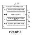
- FIG. 5illustrates an example audio encoding subsystem 302 that may be deployed in the audio encoder 106 , or otherwise deployed in another system.
- One or more modulesare included in the audio encoding subsystem 302 to enable modulation of echoes in the audio signal 104 .
- the modules of the audio encoding subsystem 302 that may be includedare a window selection module 502 , a sample module 504 , an echo value calculations module 506 , and/or a signal alteration module 508 . Other modules may also be included.
- the window selection module 502selects a number of samples for a window where modulation will occur.
- the sample module 504obtains intensity of sample values for the window of the audio signal 104 .
- a sampleis a single data point of the audio signal 104 in a single audio channel of the audio signal 104 .
- the echo value calculations module 506calculates echo values for the window.
- an echo valuehas a fraction of the intensity of a corresponding sample and is at a time delay from the corresponding sample.
- the signal alteration module 508alters the audio signal 104 in the window using a windowing function and echo values.
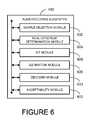
- FIG. 6illustrates an example audio decoding subsystem 402 that may be deployed in the electronic figurine 206 , or otherwise deployed in another system.
- One or more modulesare included in the audio decoding subsystem 402 to enable detecting and/or decoding of echoes in the modulated audio signals 112 .
- the modules of the audio decoding subsystem 402 that may be includedare a sample selection module 602 , a real cepstrum determination module 604 , a bit module 606 , an estimate module 608 , a decoder module 610 , and/or an acceptability module 612 .
- Other modulesmay also be included.
- the modulesmay include or represent hardware circuitry that includes and/or is coupled with one or more processors, microcontrollers, or other logic-based electronic hardware devices, such as circuits having logic hard-wired therein.
- the sample selection module 602selects a number of samples for a window of the modulated audio signal 112 .
- the modules 604 - 610(or a portion of the modules) may be used in an attempt to decode data from the modulated audio signal 112 .
- the sample selection module 602may select different samples of the window and again use the modules 604 - 612 (or a portion of the modules) in an attempt to decode data from the modulated audio signal 112 .
- the sample selection module 602may advance by ten samples (or any other number of samples) and continue to attempt to decode data from the modulated audio signal 112 .
- the sample selection module 602may continue to try different possible samples for a window until a certain qualification is met (e.g., less than a certain error rate), or may try all or a subset of the possible window sample selections and select the window sample selection with the smallest error rate. Other implementations may also be used.
- the real cepstrum determination module 604determines real cepstrum values for a window of the modulated audio signal 112 .
- the windowincludes a number of samples.
- the bit module 606compares the real cepstrum values to a threshold, identifies some of the real cepstrum values as being encoded with a positive echo based on the threshold comparison, identifies other real cepstrum values as being encoded with a negative echo based on the threshold comparison, and associates a first bit value (e.g., a bit of 1) with the real cepstrum values of the positive echo and a second bit value (e.g., a bit of 0) with the real cepstrum values of the negative echo.
- a first bit valuee.g., a bit of 1
- a second bit valuee.g., a bit of 0
- the estimate module 608estimates widths and/or means of underlying Gaussian distribution by the real cepstrum values for a number of windows.
- the decoding performed by the decoder module 610may be a soft decode or a hard decode. In some embodiments, the decoder module 610 decodes the bits obtained by the bit module 606 . In some embodiments, decoder module 610 performs a decode using the real cepstrum values, the widths of the underlying Gaussian distribution, and/or the means of the underlying Gaussian distribution using a Low Density Parity Check (LDPC) decoder based on an additive Gaussian white noise (AGWN) model.
- LDPCLow Density Parity Check
- FIG. 7Aillustrates a method 700 for audio modulation according to an example embodiment.
- the method 700adds echoes to the audio signal 104 .
- the method 700may be performed by the audio encoder 106 of the system 100 (see FIG. 1 ), or may be otherwise performed.
- An initial window of the audio signal 104may be selected at block 702 .
- Intensity values of samples in a windoware obtained at block 704 .
- the sampleis a numerical value that defines the characteristics of the audio signal 104 .
- the valuetells something (e.g., loudness) about the sound at the instant the sample was taken.
- the numeric valuemay be positive or negative and centered around zero such that zero corresponds to zero sound. In another embodiment, no sound may correspond to a numeric value of 16,000.
- the audiomay be associated with a compact disc and 44,100 samples may be taken per second of the digital audio signal.
- the audiomay be associated with a digital audio tape (DAT) and 48,000 samples may be taken per second of the digital audio signal.
- DATdigital audio tape
- the valuesmay be represented between ⁇ 0.5 and 0.5, an integer between 0 and 32,000, ⁇ 16,000 to 16,000, or the like.
- the range valuesmay be based on a format of the digital audio signal.
- a single sampleis associated with a fraction of a second for a particular channel of the audio signal 104 .
- a single sampleis associated with a fraction of a second for a particular channel of the audio signal 104 .
- a single sampleis associated with a fraction of a second for a particular channel of the audio signal 104 .
- there is one sample per fraction of a second for one channel for mono audiotwo samples per fraction of a second for two channels for stereo, and more than two samples per fraction of a second for more than two channels.
- Echo valuesare calculated for the selected window at block 706 .
- the encoding performed at block 710is, in one embodiment, performed by adding weak, windowed echoes to the given digital audio signal. If the samples are described by numbers centered so that zero corresponds to no sound, then echoing without windowing corresponds to adding a specified fraction (between 0 and 1 for a positive echo and between 0 and ⁇ 1 for a negative echo) offset by a specified time delay to the original signal sample numbers. This value may be designated as the encoding intensity parameter. If the samples are described by numbers not centered in this way, then such echoing corresponds to adding the specified fraction of the offset from the zero sound numerical value to the sample numbers. The larger the fraction, the more audible the resulting echo will be, but also the easier the resulting echo will be to decode. A specified fraction of 0 corresponds to no encoding.
- the modulated echoes that are added to the audio signal 104 at block 710may be positive echoes or negative echoes.
- a positive echois when a fraction of an intensity offset is added to a sample of a digital audio signal.
- a negative echois when a fraction of the intensity offset is subtracted from a sample of a digital audio signal.
- a positive echorepresents a data bit of 1 and a negative echo represents a data bit of 0.
- a positive echorepresents a data bit of 0 and a negative echo represents a data bit of 1.
- presence or absence of echoesare used to represent data.
- the presence of an echorepresents a data bit of 1 and the absence of an echo represents a data bit of zero.
- the presence of an echorepresents a data bit of 0 and the absence of the echo represents a data bit of 1.
- the fractionmay be a value between zero and one.
- the fractionis selected (e.g., by the audio encoder 106 or by a user of the audio encoder 106 ) based on characteristics of the underlying audio, the desired degree of perceptibility of the encoding, or both. However, other scaled values may also be used.
- the fractionis 0.15.
- the fraction of 0.15may be a value used when the resulting echo is at least substantially imperceptible. In other embodiments, the fraction is greater or less than 0.15. In some embodiments, the fraction may be calculated or otherwise altered on the fly.
- the resulting echo added to the modulated audio signal 112is at least substantially imperceptible, while in other embodiments the resulting echo is at least slightly perceptible.
- the modulating of the resulting echomay be substantially imperceptible, while the resulting echo for speech (e.g., a single person speaking) may be at least slightly perceptible.
- the added echo with the fraction of 0.15is typically around 0.03.
- the echoes of the method 700are constructed using “windows” so that the effect of modulating a specific bit is confined to the samples that are associated with a specific window.
- the windowis defined by a specified number of audio samples.
- the window lengthmay be identified as being of a particular length (N).
- the windowalso defines the wrap around length.
- the window or windowing regionspecifies a length and having a wraparound characteristic, quality or property
- the window lengthdefines a wrap-around length for the echoes.
- a (positive or negative) echoto all N samples at a time, with a time-offset of d samples. For the last d samples from the window, the time offset would lead to attempting to add to d samples which are beyond the end of the window.
- periodic boundary conditionsmay be used. For example, an echo is added to the first sample whenever the N+1 th sample would be added to (in the absence of wrap-around) and added to the m th sample whenever the N+m th sample would be used. In one embodiment, this procedure is carried out in Fourier space.
- the wrap aroundmeans that when the end of the window is reached, the echoes are added to the samples at the beginning of the window.
- This periodic boundary conditionuses the length of the window as the period.
- adding an echo or echo valueincludes taking the original signal and adding a portion of the echo at an offset in time or at a delay.
- the echois added to a sample of the audio signal 104 in a same channel.
- the echois added to a sample of the audio signal 104 in a different channel.
- the different channelmay have the same audio, at least substantially similar audio, or different audio than the channel from which the sample was taken.
- the offsetsmay be selected in advance or calculated on the fly.
- More than one echomay be added in each window, each echo corresponding to a different value of the time delay d and, in some embodiments, to a different encoding intensity parameter.
- the distinct echoesmay encode the same or distinct bits.
- double the informationmay be encoded.
- the increased informationmay be used for more accurate encoding, or transporting increased data.
- the data bits encoded in a particular windowmay be the same or different.
- the same datamay be encoded two or more times in a window. For example, a first data bit may be encoded with a delay of 48 samples, and a second one may be encoded with a delay of 96 samples. The delays need not be multiples of each other.
- the same fractionmay be used for the different echoes or multiple fractions may be used.
- different fractions and different offsetsmay be tried for audio signals in advance of decoding.
- a desired fraction and offsetmay then be selected by a user or a machine (e.g., the audio encoder 106 ) based on performance or one or more other criteria.
- the windowsmay be used so that the echo is added most strongly near the middle of the window and hardly at all at the end. This may be done to avoid audibility problems associated with wrap-around and with transitions from positive to negative echoes when different bits are encoded by distinct, neighboring windows.
- the windowingmay be carried out using overlapping windows such that that if the encoding intensity parameter is taken to be zero, then encoding using echoes in conjunction with the windowing method may lead to encoded audio that is almost unchanged (e.g., up to accuracy of computer arithmetic) from the un-encoded audio input.
- the process of using the overlapping windowsis performed in such a way that when the contributions of the overlapping windows are added, the signal is such that when decoding the un-encoded signal (up to the accuracy of computer arithmetic) would be recoverable if data were not encoded.
- the windowsmay overlap by 50%, 33%, or may otherwise overlap.
- the adding of the echo using a windowing functionreduces a possibility that the wrap around characteristic will be detected or otherwise noticed.
- the windowing functionis a sine wave of period 2 N or twice the number of samples N associated with a window that is slightly offset from zero. Other functions may be used, or other offsets may be used, or both.
- a determinationmay be made on whether to select another window. If a determination is made to select another window, another window may be selected at block 714 and the method 700 may return to block 704 . If a determination is made not to select another window at decision block 712 , the method 700 may terminate.
- a windowing function w(n)may be defined for N values associated with a window.
- the process of “windowing”includes multiplying each of the N audio sample values with the corresponding value of the w function.
- the windowing functionhas the property that the underlying audio signal is at least substantially unchanged when no echo is added.
- the windowing function w(n)satisfies two criteria.
- the first criterionis that the output of the function be small near both the beginning and the end of the series of N values for which it is defined.
- the second criterionis that applying the encoding algorithm will lead to the unchanged condition.
- H(k)is defined to be unity for all N distinct values of k.
- proportional to the encoding intensity value for a positive or negative echodepending on whether a “1” or a “0” is to be encoded in that echo. It may also be proportional to the discrete Fourier transform of the delta function ⁇ (n ⁇ d) where n is a sample index and d is the time delay offset for that echo measured in samples.
- multiplication of the Fourier space samples to be encoded by the corresponding H(k) terms of the samples, followed by additional windowing and performance of an inverse discrete Fourier transform on the results,is equivalent to adding echoes to the audio signal 104 with wrap-around.
- the Fourier transformis a fast Fourier transform.
- each sampleis be encoded twice—once in a window and once in an overlapping window that is offset by half the window length.
- the encoding of the samplesmay be schematically represented by overlapping arcs.
- An example embodiment of an implementation of the audio modulation methodis as follows: A sample is multiplied by the windowing function, the result is added to the echo, and that result is then multiplied by the windowing function again. The offset is then increased by half a window length and the process is repeated. Half of the samples in the window length will then be handled by both the first window and the second window. The answers from both of these components are then added.
- the number of echoes to be encoded in each set of samples of length Nmay be selected.
- a corresponding time delay for each of the echoesmay also be selected.
- two echoes in each set of N samples with time delays of 30 and 60 samplesmay be respectively selected.
- a method for determining the encoding intensity parametersmay be selected.
- the positive and negative parametersmay be of the same or different magnitude (though of different signs) for positive and negative echoes.
- the parametersmay be the same or different for each of the distinct echoes encoded in a set of N samples. They may be constant for an entire piece of audio content or else be determined adaptively, optionally having different values for different parts of the audio content. The values may be chosen depending on the characteristics of the audio content or on other factors, including the degree of audibility acceptable for the given application
- the bits to be encodedmay be selected.
- the bitsmay include both content bits and bits used for error correction.
- N samples of the audio content signalmay be obtained.
- bits to be encodedare selected.
- the N samplesare windowed.
- the discrete Fourier transform of the windowed samplesis calculated.
- the discrete inverse Fourier transform of result of the multiplicationis calculated.
- the resulting valuesare indexed N/2+1 to N inclusive, and the resulting values are stored.
- the resulting values indexed 1 to N/2 inclusiveare taken and added to the stored values obtained from the previous pass of this procedure.
- the resultsare the final encoded values for these N/2 samples.
- the procedureis repeated with N samples starting with an offset of N/2 samples from the previous samples, so that the samples indexed N/2+1 to N inclusive from this pass are used as the samples indexed 1 to N/2 inclusive during the next pass.
- the procedureis repeated one or more times to encode a portion or all of the entire audio content of the audio signal 104 , each time using a set of N samples which overlap the previous set by N/2 samples (or N/3 samples in another embodiment).
- the proceduremay be adapted for the first N/2 and final N/2 samples of content that as a result may or may not be encoded in an actual embodiment.
- the modulationmay be performed in any one channel, in a combination of several channels, or in all channels that are defined for the audio content of the audio signal 104 .
- bit value onemay be represented by an echo and the bit value zero may be represented by absence of echo. In one embodiment, the bit value zero may be represented by an echo and the bit value one may be represented by absence of echo.
- FIG. 7Billustrates a method 750 for bit selection according to an example embodiment.
- the method 750may be used to select bits for echo modulation of audio signal 104 .
- the method 750may be performed by the audio encoder 106 of the system 100 (see FIG. 1 ), or may be otherwise performed.
- one or more content bitsare selected for encoding.
- the number of content bitsmay be a few bits, tens of bits, hundreds of bits, or an even larger number of bits.
- content bitsare encoded using an LDPC method with the content bits as input and a larger number of bits as output. These bits are designated as the BASIC LDPC BITS.
- additional bitsmay be encoded as BASIC synchronization bits in a pattern that can be made known to the detection device 206 (see FIG. 2 ).
- the BASIC synchronization bitsare inserted into the bit stream of the output of the LDPC encoding step performed at block 754 in positions that may be made known to the detection device 206 .
- each bit from the output of the operations performed at block 758may be repeated several times at block 760 .
- each 1 bitmight be represented by the 4 bits 1010 in that order and each 0 bit might be represented by the 4 bits 0101 in that order.
- the repeated or generated bits obtained from the BASIC synchronization bitsmay be referred to as enhanced synchronization bits.
- the repeated or generated buts obtained from the basic LDPC bitsmay be referred to as enhanced LDPC bits.
- FIG. 8is an illustration 800 of a first window 802 , according to an example embodiment.
- the first window 802may be used in encoding, or may be otherwise used.
- the first window 802is shown as half a sine wave in a graph with intensity over time.
- FIG. 9is an illustration 900 of a second window 902 , according to an example embodiment.
- the second window 902may be used in encoding, or may be otherwise used.
- the second window 902is shown as half a sine wave in a graph with intensity over time.
- FIG. 10is an illustration 1000 of the overlapping of the first window 802 and the second window 902 , according to an example embodiment.
- the overlapping windows 802 , 902share an overlapping section 1002 .
- FIG. 11is an illustration 1100 of the application of a periodic boundary condition, according to an example embodiment.
- a first set of samples 1102are offset two samples from a second set of samples 1104 .
- the relationship between the samplesis such that the echo from sample 1 of the first set of samples 1102 would be added to sample 3 of the second set of samples 1104 , the echo from sample 2 of the first set of samples 1104 would be added to sample 4 of the second set of samples 1104 , and so on.
- These relationships 1106are shown in the illustration 1100 .
- FIG. 12is an illustration 1200 of a set of samples 1202 according to an example embodiment.
- the illustration 1200shows an initial signal for unencoded audio.
- the value of the intensity of the set of samples 1202is shown in the illustration 1200 as having a maximum value of 1.
- FIG. 13is an illustration 1300 of a set of samples 1302 according to an example embodiment.
- the set of samples 1302may be a positive echo of the set of samples 1202 (see FIG. 12 ).
- the value of the intensity of the set of samples 1302is shown in the illustration 1300 as having a maximum value of 1 ⁇ 2.
- FIG. 14is an illustration 1400 of a set of samples 1402 according to an example embodiment.
- the set of samples 1402may be a negative echo of the set of samples 1202 (see FIG. 12 ).
- the value of the intensity of the set of samples 1402is shown in the illustration 1400 as having a minimum value of ⁇ 1 ⁇ 2.
- FIG. 15is an illustration 1500 of the sets of samples 1202 , 1302 , 1402 , according to an example embodiment.
- the illustration 1500shows the initial with two echoes on the same scale.
- FIG. 16is an illustration 1600 of a result of adding the sets of samples 1202 , 1302 , 1402 together, according to an example embodiment.
- the result of the combination of the sets of samples 1202 , 1302 , 1402is an encoded signal 1602 .
- FIG. 17Aillustrates a method 1700 for audio decoding, according to an example embodiment.
- the method 1700may be performed by the detection device 206 of the system 200 (see FIG. 2 ), or may be otherwise performed.
- the method 1700determines whether echoes are present in the modulated audio signal 112 and, when present, whether the echoes are positive echoes or negative echoes.
- the encoded ones and zerosmay then be decoded by detecting positive or negative echoes.
- a starting sample for a windowmay be selected at block 1702 .
- the window lengthmay be taken at an arbitrary position for N samples at a time.
- a supposition of the start of windowmay be made and then either all the possibilities (e.g., incrementing the window by a sample at a time) or some of the possibilities may be tried. For example, a decoding attempt may be made every 1/10 of the window length. However, attempts may be made more or less frequently. The number of attempts that are made may be based on the type of application, particular decoding need, or both. Even when the supposition is not exactly correct, decoding may still be possible with error correction.
- the real cepstrum values for the windowmay be determined at block 1704 .
- a number of bit valuesmay be determined based on a comparison against a threshold value at block 1706 .
- a threshold valueFor example, real cepstrum values above a threshold may be determined to be one type of echo (e.g., a positive echo), while real cepstrum values equal to or below a threshold may be another type of echo (e.g., a negative echo).
- a cepstrum value that is greater than (or possibly equal to) some thresholdis taken as the evidence that the decoding of a bit that was encoded by a positive echo, and a cepstrum value that is less than (or possibly equal to) the same or different threshold is taken as evidence that the decoding of the bit that was encoded by a negative echo.
- the threshold usedmay be either a fixed value, or alternatively a value determined adaptively using, for example, the statistical properties of measured cepstrum values. Some cepstrum values may be designated as ambiguous if they lie between the threshold values.
- the mean of some subset of cepstrum valuesif it is assumed or otherwise known that an approximately equal number of positive and negative echoes were encoded in the corresponding audio samples.
- the subsetmay optionally (but need not) be the set associated with a particular data packet.
- itmay be the 25 th percentile of the measured distribution of some subset of cepstrum values if it is assumed or otherwise known that approximately 25% of the echoes encoded were negative echoes.
- the result of applying this threshold or these thresholds, together with knowledge of the relationship between positive and negative echoes,may then provide an estimated set of 0's and 1's and designated ambiguous values. These values may be used as input to a “hard” decode error correction decoder. Alternatively, the real cepstrum values may be used as inputs to a soft error correction decoder.
- the decodingis a hard decode where a number of occurrences of numbers above and below some threshold are counted to obtain a result. In other embodiments, the decoding is a soft decode where positive and negative numbers are added to obtain a result.
- a soft repetition codemay be used for decoding.
- the soft repetition codemay be used to recover the data when multiple echoes have been encoded in one or more windows with the same data.
- the soft repetition codemay be used by looking at real cepstrum numbers.
- the soft decode on the windowmay include adding the resulting numbers together.
- real valuesare added from the echoes in the multiple windows to obtain the cepstrum number.
- a first resulte.g., a data bit of one
- a second resultmay be decoded (e.g., a data bit of zero).
- further processingis performed on the cepstrum numbers before identifying a result.
- the type of decoding performedis blind decoding. A comparison to the original, unencoded audio is not performed during the decoding process. By not needing the original audio, additional opportunities for decoding in different environments may be available.
- the decoding methodmay further include a comparison between a first channel and a second channel.
- the bits encodedmay be both content bits and extra bits added to enable error correction. Methods of adding extra bits and the associated error correction methods that recover data encoded in this way are described. The methods may be combined and be used to provide a synchronization method.
- Two decoding methodsare “soft” decoding error correction methods in that they use combinations of the real values generated by the decoder (where the number of such real values is the same as the total number of content bits and extra bits added to enable error correction) to generate estimates of the content bits.
- “Hard” decodingwhich uses 1's and 0's as input to the decoder may also be used.
- FIG. 17Billustrates a method 1750 for audio decoding, according to an example embodiment.
- the method 1750may be performed by the detection device 206 of the system 200 (see FIG. 2 ), or may be otherwise performed.
- a candidate starting sample for a windowis selected at block 1752 .
- the real cepstrum values for a series of windows corresponding to the encoded bits for which a search is to be performedmay be obtained.
- the error correctionis always carried out at the operations performed at decision block 1756 may be omitted.
- the error correctionmay be performed depending on the characteristics of the audio as measured by the audio decoding subsystem 402 .
- the error correction decodemay be performed depending on the computer resources available to the audio decoding subsystem 402 at the time of decoding.
- the decision to perform the error correction decodeis based on the synchronization parameters. Using the known positions of the cepstrum values corresponding to the enhanced synchronization bits, and assuming the candidate starting sample is correct or approximately correct, generate the corresponding bit values of the synchronization bits. If these values are close enough to the values of the synchronization values as encoded then the error correction decode is performed.
- generate the basic synchronization bitsusing a hard decode for each value to generate the basic synchronization bits.
- a soft decodeis used to generate the basic synchronization bits.
- a comparison of the pattern of basic and/or enhanced synchronization bitsmay be performed with the error correction decode if the match is close enough to some threshold.
- more than one criterionmay be used.
- the criteria listed in other embodiments abovemay be used to determine whether the error correction decode should be performed.
- soft decoding methodsmay be used at block 1758 on the real cepstrum values corresponding to enhanced error correction bits to obtain real values corresponding to the basic error correction bits. These values may be used as inputs to the error correction soft decode.
- a soft decodemay be performed on the real cepstrum values at block 1758 corresponding to the enhanced bits to obtain real cepstrum values corresponding to the basic bits and threshold those values to obtain bit values to be used for a hard error correction decode.
- a determinationmay be made as to whether there is another sample. If a determination is made that there is another sample, a next window may be selected at block 1762 and the method 1700 may return to block 1754 . If a determination is made at decision block 1760 that there is not another sample, the method 1700 may terminate.
- one or more of the foregoing methodsmay be used as a quick-to-calculate method for generating candidates for alignment (synchronization).
- FIG. 18is an illustration 1800 of a windowing function 1802 , according to an example embodiment.
- the windowing function 1802may be used in decoding, or may be otherwise used.
- the windowing function 1802is shown as half a sine wave in a graph with intensity over time.
- FIG. 19is an illustration 1900 of cepstrum values, according to an example embodiment.
- the cepstrum values 1900are shows as cepstrum values 1902 , 1904 .
- the cepstrum values 1902 , 1904are shown in a graph with Q-intensity over Q-frequency. As shown the cepstrum values 1902 , 1904 reflect different echo time delays. While the cepstrum values 1902 , 1904 are represented in the illustration 1900 as Q values, they may also represent K values in other illustrations.
- FIG. 20illustrates a method 200 for audio decoding, according to an example embodiment.
- the method 1700may be performed by the detection device 206 of the system 200 (see FIG. 2 ), or may be otherwise performed.
- the method 2000determines whether echoes are present in the modulated audio signal 112 and, when present, whether the echoes are positive echoes or negative echoes.
- the encoded ones and zerosmay then be decoded by detecting positive or negative echoes or the absence of an echo may indicate an encoded zero or one depending on the protocol used to encode.
- a starting sample for a windowmay be selected at block 2002 .
- Real cepstrum values for the modulated audio signal 112are determined at block 2004 .
- estimates of the widths of underlying Gaussian distribution by the real cepstrum valuesare determined at block 2006 .
- estimates of the means of underlying Gaussian distribution by the real cepstrum valuesare determined at block 2008 .
- a soft decodedis performed at block 201 on the real cepstrum values, the widths of the underlying Gaussian distribution, and/or the means of the underlying Gaussian distribution using a Low Density Parity Check (LDPC) decoder based on an additive Gaussian white noise (AGWN) model.
- LDPCLow Density Parity Check
- AGWNadditive Gaussian white noise
- a low-density parity check (LDPC) codemay be used on the cepstrum numbers at block 2010 .
- the LDPC codemay be used by calculating an estimate of the width and/or means of a Gaussian distribution. The estimate or a value larger than the estimate may be used as an input to the LDPC with the real cepstrum numbers (e.g., resulting from the soft repetition code) used to estimate the encoded data bits.
- the LDPC codemay be used for error correction when the noise pattern from the modulated audio signal approximates additive white Gaussian noise (AWGN) or the distribution of the cepstrum values approximates samples drawn from two bell curves that may be offset from each other.
- the noise patternmay be from the underlying audio, the broadcasting path, digital to analog conversions, encoding, or the like.
- a repetition decodemay be performed as follows.
- the content bits to be encodedare repeated a known number of times.
- the copies of the content bits(to be regarded as “extra bits” used for error correction) are then arranged in a known order with regard to the content bits.
- the copiesmay or may not be contiguous to their original content bits. This combination of content and error bits is what was previously encoded.
- the real cepstrum valuesin one embodiment, associated with each content bit and its copies are added, to produce one combined real cepstrum value for each content bit.
- These combined real cepstrum valuesmay be used for thresholding to perform a hard decode or as values on which a soft decode is to be performed. In the case of hard decoding, the closeness of a combined (or not combined) real cepstrum value to the threshold may be used as a guide as to whether a particular bit should be ignored by the decoder.
- the content bitsmay be encoded using a Low Density Parity Check (LDPC) encoder or another encoder to produce content bits and additional bits (“parity bits”) to enable error correction.
- LDPCLow Density Parity Check
- the resulting bitsmay be encoded using repetition encoding.
- the resulting bit streamis then encoded as described above.
- the decoderfirst performs a repetition decoding on the real cepstrum values, returning one combined real cepstrum value for each content bit and one combined real cepstrum value for each parity bit. These combined real cepstrum values may be used as input to the relevant soft decoder (e.g.
- the repetition decodermay be used with thresholding and its output used as input to the relevant hard decoder (e.g. a hard LDPC decoder if the encoding was LDPC.).
- a LDPC decoder using a soft decode based on an additive white Gaussian noise modelmay be used for decoding audio signals that have or have not passed through broadcast channels, whether or not the data are strictly the sum of data taken from Gaussian distributions.
- the modeluses input of an estimate of the noise variance.
- One embodiment of estimating the varianceassumes that an approximately equal number of positive and negative echoes were encoded. The assumption is that the distribution of the input real cepstrum values (or combined real cepstrum values if a repetition encoder was used) is a sum of values drawn from two Gaussian or approximately Gaussian distributions which have different means and possibly different variances.
- the variance of the upper Gaussianis estimated by calculating the mean square distance from the 75.sup.th percentile of data between the 75 th and 100 th percentile of the combined distribution of the input real cepstrum values.
- the variance of the lower Gaussianis estimated by calculating the mean square distance from the 25 th percentile of data between the 0 th and 25 th percentile of the combined distribution of the input real cepstrum values. The larger of these values is used as a guide to the estimated variance to be input; being regarded as a lower bound on a suitable value to be used for the decoder.
- Another embodimentmay use a constant value for the variance based, for example, on knowledge of the transmission path of the audio since encoding.
- FIG. 21illustrates a method 2100 for calculating cepstrum values, according to an example embodiment.
- the method 2100may be performed at the block 1704 , block 2004 , or may be otherwise performed.
- a windowing functionis applied to a number of samples create windowed samples.
- a Fourier transformis performed windowed samples to create transformed samples.
- the Fourier transformis a Fast Fourier Transform.
- An absolute valueis calculated for the transformed samples to create absolute value samples at block 2106 .
- a determinationmay be made as to whether any of the absolute value samples have a zero value. If a determination is made that some of the absolute value samples have a zero value, the zero value of the absolute value samples may be replaced by a small number at block 2110 . If a determination made that none of the absolute values have a zero value at decision block 2108 or upon completion of the operations at block 2110 , the method 2100 may proceed to block 2112 .
- Logarithms of the absolute value samplesare calculated at block 2114 to create logged samples.
- Inverse Fourier transformsare performed on the logged samples at block 2116 to obtain cepstrum values.
- the inverse Fourier transformis an inverse Fast Fourier Transform.
- a real portion of the cepstrum valuesare selected at block 2118 as a real cepstrum values.
- the selection performed at block 2118includes selecting the cepstrum values that correspond to the echo time delays. For example, if the delays were 48 samples and 96 samples, take the 49 th and 97 th cepstrum values (not the 48 th and 96 th values).
- FIG. 22shows a block diagram of a machine in the example form of a computer system 2200 within which a set of instructions may be executed causing the machine to perform any one or more of the methods, processes, operations, or methodologies discussed herein.
- the signal source 102 , the broadcast source 112 , or bothmay operate on one or more computer systems 2200 .
- the audio encoder 106 , the audio receives 202 , the display device 204 , and/or the detection device 206may include the functionality of the one or more computer systems 2200 .
- the machineoperates as a standalone device or may be connected (e.g., networked) to other machines.
- the machinemay operate in the capacity of a server or a client machine in server-client network environment, or as a peer machine in a peer-to-peer (or distributed) network environment.
- the machinemay be a server computer, a client computer, a personal computer (PC), a tablet PC, a set-top box (STB), a Personal Digital Assistant (PDA), a cellular telephone, a web appliance, a network router, switch or bridge, a kiosk, a point of sale (POS) device, a cash register, an Automated Teller Machine (ATM), or any machine capable of executing a set of instructions (sequential or otherwise) that specify actions to be taken by that machine.
- POSpoint of sale
- ATMAutomated Teller Machine
- machineshall also be taken to include any collection of machines that individually or jointly execute a set (or multiple sets) of instructions to perform any one or more of the methodologies discussed herein.
- the example computer system 2200includes a processor 2212 (e.g., a central processing unit (CPU) a graphics processing unit (GPU) or both), a main memory 2204 and a static memory 2206 , which communicate with each other via a bus 2208 .
- the computer system 2200may further include a video display unit 2210 (e.g., a liquid crystal display (LCD) or a cathode ray tube (CRT)).
- the computer system 2200also includes an alphanumeric input device 2212 (e.g., a keyboard), a cursor control device 2214 (e.g., a mouse), a drive unit 2216 , a signal generation device 2218 (e.g., a speaker) and a network interface device 2220 .
- the drive unit 2216includes a computer-readable medium 2222 on which is stored one or more sets of instructions (e.g., software 2224 ) embodying any one or more of the methodologies or functions described herein.
- the software 2224may also reside, completely or at least partially, within the main memory 2204 and/or within the processor 2212 during execution thereof by the computer system 2200 , the main memory 2204 and the processor 2212 also constituting computer-readable media.
- the software 2224may further be transmitted or received over a network 2226 via the network interface device 2220 .
- While the computer-readable medium 2222is shown in an example embodiment to be a single medium, the term “computer-readable medium” should be taken to include a single medium or multiple media (e.g., a centralized or distributed database, and/or associated caches and servers) that store the one or more sets of instructions.
- the term “computer-readable medium”shall also be taken to include any medium that is capable of storing or encoding a set of instructions for execution by the machine and that cause the machine to perform any one or more of the methodologies of the inventive subject matter.
- the term “computer-readable medium”shall accordingly be taken to include, but not be limited to, solid-state memories, and optical media, and magnetic media.
- a modulemay be a unit of distinct functionality that may be presented in software, hardware, or combinations thereof.
- the functionality of a moduleis performed in any part through software, the module includes a computer-readable medium.
- the modulesmay be regarded as being communicatively coupled.
- inventive subject mattermay be represented in a variety of different embodiments of which there are many possible permutations.
Landscapes
- Engineering & Computer Science (AREA)
- Physics & Mathematics (AREA)
- Acoustics & Sound (AREA)
- Multimedia (AREA)
- Spectroscopy & Molecular Physics (AREA)
- Computational Linguistics (AREA)
- Signal Processing (AREA)
- Health & Medical Sciences (AREA)
- Audiology, Speech & Language Pathology (AREA)
- Human Computer Interaction (AREA)
- Two-Way Televisions, Distribution Of Moving Picture Or The Like (AREA)
- Signal Processing For Digital Recording And Reproducing (AREA)
Abstract
Description
w(n+N/2)2+w(n)2=1
w(n+2N/3)2+w(n+N/3)2+w(n)2=1
w(n)=sin(π(t−0.5)/N)
defined for n=1 to N inclusive.
Claims (18)
Priority Applications (1)
| Application Number | Priority Date | Filing Date | Title |
|---|---|---|---|
| US14/045,318US9484011B2 (en) | 2009-01-20 | 2013-10-03 | Echo modulation methods and system |
Applications Claiming Priority (3)
| Application Number | Priority Date | Filing Date | Title |
|---|---|---|---|
| US14577609P | 2009-01-20 | 2009-01-20 | |
| US12/690,814US8582781B2 (en) | 2009-01-20 | 2010-01-20 | Echo modulation methods and systems |
| US14/045,318US9484011B2 (en) | 2009-01-20 | 2013-10-03 | Echo modulation methods and system |
Related Parent Applications (1)
| Application Number | Title | Priority Date | Filing Date |
|---|---|---|---|
| US12/690,814ContinuationUS8582781B2 (en) | 2009-01-20 | 2010-01-20 | Echo modulation methods and systems |
Publications (2)
| Publication Number | Publication Date |
|---|---|
| US20140064505A1 US20140064505A1 (en) | 2014-03-06 |
| US9484011B2true US9484011B2 (en) | 2016-11-01 |
Family
ID=42336969
Family Applications (2)
| Application Number | Title | Priority Date | Filing Date |
|---|---|---|---|
| US12/690,814Active2032-09-14US8582781B2 (en) | 2009-01-20 | 2010-01-20 | Echo modulation methods and systems |
| US14/045,318Active2031-05-18US9484011B2 (en) | 2009-01-20 | 2013-10-03 | Echo modulation methods and system |
Family Applications Before (1)
| Application Number | Title | Priority Date | Filing Date |
|---|---|---|---|
| US12/690,814Active2032-09-14US8582781B2 (en) | 2009-01-20 | 2010-01-20 | Echo modulation methods and systems |
Country Status (1)
| Country | Link |
|---|---|
| US (2) | US8582781B2 (en) |
Families Citing this family (4)
| Publication number | Priority date | Publication date | Assignee | Title |
|---|---|---|---|---|
| US8582781B2 (en)* | 2009-01-20 | 2013-11-12 | Koplar Interactive Systems International, L.L.C. | Echo modulation methods and systems |
| US9305559B2 (en)* | 2012-10-15 | 2016-04-05 | Digimarc Corporation | Audio watermark encoding with reversing polarity and pairwise embedding |
| CN106847299B (en)* | 2017-02-24 | 2020-06-19 | 喜大(上海)网络科技有限公司 | Time delay estimation method and device |
| WO2019083845A1 (en) | 2017-10-26 | 2019-05-02 | Brian Handrigan | Online advertising and promotional coordination system |
Citations (78)
| Publication number | Priority date | Publication date | Assignee | Title |
|---|---|---|---|---|
| US3622108A (en)* | 1970-02-27 | 1971-11-23 | George A Mathewson | Safety device for disabled airplanes |
| US5893067A (en)* | 1996-05-31 | 1999-04-06 | Massachusetts Institute Of Technology | Method and apparatus for echo data hiding in audio signals |
| US6122610A (en) | 1998-09-23 | 2000-09-19 | Verance Corporation | Noise suppression for low bitrate speech coder |
| US6145081A (en) | 1998-02-02 | 2000-11-07 | Verance Corporation | Method and apparatus for preventing removal of embedded information in cover signals |
| US6175627B1 (en) | 1997-05-19 | 2001-01-16 | Verance Corporation | Apparatus and method for embedding and extracting information in analog signals using distributed signal features |
| US6430301B1 (en) | 2000-08-30 | 2002-08-06 | Verance Corporation | Formation and analysis of signals with common and transaction watermarks |
| US20020168087A1 (en) | 2001-05-11 | 2002-11-14 | Verance Corporation | Watermark position modulation |
| US20030014634A1 (en) | 2001-04-06 | 2003-01-16 | Verance Corporation | Methods and apparatus for embedding and recovering watermarking information based on host-matching codes |
| US20030018709A1 (en) | 2001-07-20 | 2003-01-23 | Audible Magic | Playlist generation method and apparatus |
| US20030033321A1 (en) | 2001-07-20 | 2003-02-13 | Audible Magic, Inc. | Method and apparatus for identifying new media content |
| US20030037010A1 (en) | 2001-04-05 | 2003-02-20 | Audible Magic, Inc. | Copyright detection and protection system and method |
| US20030135623A1 (en) | 2001-10-23 | 2003-07-17 | Audible Magic, Inc. | Method and apparatus for cache promotion |
| US20040073916A1 (en) | 2002-10-15 | 2004-04-15 | Verance Corporation | Media monitoring, management and information system |
| US20040163106A1 (en) | 2003-02-01 | 2004-08-19 | Audible Magic, Inc. | Method and apparatus to identify a work received by a processing system |
| US20040169581A1 (en) | 2000-02-16 | 2004-09-02 | Verance Corporation | Remote control signaling using audio watermarks |
| US6792542B1 (en) | 1998-05-12 | 2004-09-14 | Verance Corporation | Digital system for embedding a pseudo-randomly modulated auxiliary data sequence in digital samples |
| US6834308B1 (en) | 2000-02-17 | 2004-12-21 | Audible Magic Corporation | Method and apparatus for identifying media content presented on a media playing device |
| US6888943B1 (en) | 1998-04-21 | 2005-05-03 | Verance Corporation | Multimedia adaptive scrambling system (MASS) |
| US20050196051A1 (en) | 1998-05-28 | 2005-09-08 | Verance Corporation | Pre-processed information embedding system |
| US6947509B1 (en) | 1999-11-30 | 2005-09-20 | Verance Corporation | Oversampled filter bank for subband processing |
| US6968337B2 (en) | 2001-07-10 | 2005-11-22 | Audible Magic Corporation | Method and apparatus for identifying an unknown work |
| US20060034177A1 (en) | 2004-07-28 | 2006-02-16 | Audible Magic Corporation | System for distributing decoy content in a peer to peer network |
| US7046808B1 (en) | 2000-03-24 | 2006-05-16 | Verance Corporation | Method and apparatus for detecting processing stages applied to a signal |
| US20060239502A1 (en) | 2005-04-26 | 2006-10-26 | Verance Corporation | Methods and apparatus for enhancing the robustness of watermark extraction from digital host content |
| US20060239501A1 (en) | 2005-04-26 | 2006-10-26 | Verance Corporation | Security enhancements of digital watermarks for multi-media content |
| US20060239503A1 (en) | 2005-04-26 | 2006-10-26 | Verance Corporation | System reactions to the detection of embedded watermarks in a digital host content |
| US20070039018A1 (en) | 2005-08-09 | 2007-02-15 | Verance Corporation | Apparatus, systems and methods for broadcast advertising stewardship |
| US20070074147A1 (en) | 2005-09-28 | 2007-03-29 | Audible Magic Corporation | Method and apparatus for identifying an unknown work |
| US20070110237A1 (en) | 2005-07-07 | 2007-05-17 | Verance Corporation | Watermarking in an encrypted domain |
| US20080002854A1 (en) | 2003-10-08 | 2008-01-03 | Verance Corporation | Signal continuity assessment using embedded watermarks |
| US20090031326A1 (en) | 2007-07-27 | 2009-01-29 | Audible Magic Corporation | System for identifying content of digital data |
| US7519347B2 (en)* | 2005-04-29 | 2009-04-14 | Tandberg Telecom As | Method and device for noise detection |
| US7533266B2 (en) | 2002-02-01 | 2009-05-12 | Civolution B.V. | Watermark-based access control method and device |
| US7562012B1 (en) | 2000-11-03 | 2009-07-14 | Audible Magic Corporation | Method and apparatus for creating a unique audio signature |
| US7639599B2 (en) | 2001-11-16 | 2009-12-29 | Civolution B.V. | Embedding supplementary data in an information signal |
| US20100046606A1 (en) | 2007-01-12 | 2010-02-25 | Civolution B.V. | Video watermarking |
| US7779271B2 (en) | 2001-11-23 | 2010-08-17 | Civolution B.V. | Watermark embedding |
| US7844072B2 (en) | 2003-01-20 | 2010-11-30 | Civolution B.V. | Watermark embedding and detection of a motion image signal |
| US20110066723A1 (en) | 2008-03-18 | 2011-03-17 | Civolution B.V. | Generating statistics of popular content |
| US7996678B2 (en) | 2001-06-21 | 2011-08-09 | Civolution B.V. | Embedding and detection of watermark in a motion image signal |
| US8085935B2 (en) | 1997-05-19 | 2011-12-27 | Verance Corporation | Embedding and extraction of information from an embedded content using replica modulation |
| US20120072730A1 (en) | 2010-09-16 | 2012-03-22 | Verance Corporation | Context access management using watermark extraction information |
| US8180098B2 (en) | 2002-05-22 | 2012-05-15 | Civolution B.V. | Method of extracting a watermark |
| US8199651B1 (en) | 2009-03-16 | 2012-06-12 | Audible Magic Corporation | Method and system for modifying communication flows at a port level |
| US8259938B2 (en) | 2008-06-24 | 2012-09-04 | Verance Corporation | Efficient and secure forensic marking in compressed |
| US8355511B2 (en)* | 2008-03-18 | 2013-01-15 | Audience, Inc. | System and method for envelope-based acoustic echo cancellation |
| US8391471B2 (en)* | 2007-08-24 | 2013-03-05 | Fujitsu Limited | Echo suppressing apparatus, echo suppressing system, echo suppressing method and recording medium |
| US20130152210A1 (en) | 2011-12-13 | 2013-06-13 | Verance Corporation | Coordinated watermarking |
| US20130151856A1 (en) | 2011-12-13 | 2013-06-13 | Verance Corporation | Conditional access using embedded watermarks |
| US20130151855A1 (en) | 2011-12-13 | 2013-06-13 | Verance Corporation | Watermark embedding workflow improvements |
| US8467538B2 (en)* | 2008-03-03 | 2013-06-18 | Nippon Telegraph And Telephone Corporation | Dereverberation apparatus, dereverberation method, dereverberation program, and recording medium |
| US8560913B2 (en)* | 2008-05-29 | 2013-10-15 | Intrasonics S.A.R.L. | Data embedding system |
| US8582781B2 (en)* | 2009-01-20 | 2013-11-12 | Koplar Interactive Systems International, L.L.C. | Echo modulation methods and systems |
| US8601504B2 (en) | 2002-06-20 | 2013-12-03 | Verance Corporation | Secure tracking system and method for video program content |
| US8615104B2 (en) | 2011-11-03 | 2013-12-24 | Verance Corporation | Watermark extraction based on tentative watermarks |
| US20140032555A1 (en) | 2012-06-07 | 2014-01-30 | Honeywell International Inc. | System and method to classify telemetry from automation systems |
| US20140059591A1 (en) | 2011-02-24 | 2014-02-27 | Civolution B.V. | Broadcasting an information signal having special content for triggering an appropriate action in a user device |
| US20140067950A1 (en) | 2012-08-31 | 2014-03-06 | Verance Corporation | Social media viewing system |
| US20140075465A1 (en) | 2012-09-13 | 2014-03-13 | Verance Corporation | Time varying evaluation of multimedia content |
| US20140074855A1 (en) | 2012-09-13 | 2014-03-13 | Verance Corporation | Multimedia content tags |
| US20140075469A1 (en) | 2012-09-13 | 2014-03-13 | Verance Corporation | Content distribution including advertisements |
| US8682026B2 (en) | 2011-11-03 | 2014-03-25 | Verance Corporation | Efficient extraction of embedded watermarks in the presence of host content distortions |
| US20140089307A1 (en) | 2012-09-25 | 2014-03-27 | Audible Magic Corporation | Using digital fingerprints to associate data with a work |
| US8745403B2 (en) | 2011-11-23 | 2014-06-03 | Verance Corporation | Enhanced content management based on watermark extraction records |
| US20140196071A1 (en) | 2011-06-21 | 2014-07-10 | Civolution B.V. | Rendering device with content substitution |
| US20140267907A1 (en) | 2013-03-13 | 2014-09-18 | Verance Corporation | Multimedia presentation tracking in networked environment |
| US20140270337A1 (en) | 2013-03-14 | 2014-09-18 | Verance Corporation | Transactional video marking system |
| US20140279296A1 (en) | 2013-03-15 | 2014-09-18 | Verance Corporation | Referred sale system |
| US20140270340A1 (en) | 2011-10-10 | 2014-09-18 | Civolution B.V. | Watermark detection with payload |
| US8869222B2 (en) | 2012-09-13 | 2014-10-21 | Verance Corporation | Second screen content |
| US20140325673A1 (en) | 2013-04-25 | 2014-10-30 | Verance Corporation | Live broadcast content protection based on watermarking |
| US20140376723A1 (en) | 2013-06-20 | 2014-12-25 | Verance Corporation | Stego key management |
| US8923548B2 (en) | 2011-11-03 | 2014-12-30 | Verance Corporation | Extraction of embedded watermarks from a host content using a plurality of tentative watermarks |
| US20150019653A1 (en) | 2013-07-15 | 2015-01-15 | Civolution B.V. | Method and system for adding an identifier |
| US20150030200A1 (en) | 2013-07-23 | 2015-01-29 | Verance Corporation | Watermark extractor enhancements based on payload ranking |
| US20150043768A1 (en) | 2012-03-21 | 2015-02-12 | Civolution B.V. | Method and system for embedding and detecting a pattern |
| US9009482B2 (en) | 2005-07-01 | 2015-04-14 | Verance Corporation | Forensic marking using a common customization function |
| US20150121534A1 (en) | 2013-10-25 | 2015-04-30 | Verance Corporation | Content management using multiple abstraction layers |
Family Cites Families (5)
| Publication number | Priority date | Publication date | Assignee | Title |
|---|---|---|---|---|
| JP4345225B2 (en)* | 2000-11-27 | 2009-10-14 | 沖電気工業株式会社 | Echo canceller |
| FR2908003B1 (en)* | 2006-10-26 | 2009-04-03 | Parrot Sa | METHOD OF REDUCING RESIDUAL ACOUSTIC ECHO AFTER ECHO SUPPRESSION IN HANDS-FREE DEVICE |
| US8189766B1 (en)* | 2007-07-26 | 2012-05-29 | Audience, Inc. | System and method for blind subband acoustic echo cancellation postfiltering |
| US8208621B1 (en)* | 2007-10-12 | 2012-06-26 | Mediatek Inc. | Systems and methods for acoustic echo cancellation |
| US8472616B1 (en)* | 2009-04-02 | 2013-06-25 | Audience, Inc. | Self calibration of envelope-based acoustic echo cancellation |
- 2010
- 2010-01-20USUS12/690,814patent/US8582781B2/enactiveActive
- 2013
- 2013-10-03USUS14/045,318patent/US9484011B2/enactiveActive
Patent Citations (127)
| Publication number | Priority date | Publication date | Assignee | Title |
|---|---|---|---|---|
| US3622108A (en)* | 1970-02-27 | 1971-11-23 | George A Mathewson | Safety device for disabled airplanes |
| US5893067A (en)* | 1996-05-31 | 1999-04-06 | Massachusetts Institute Of Technology | Method and apparatus for echo data hiding in audio signals |
| US6175627B1 (en) | 1997-05-19 | 2001-01-16 | Verance Corporation | Apparatus and method for embedding and extracting information in analog signals using distributed signal features |
| US8085935B2 (en) | 1997-05-19 | 2011-12-27 | Verance Corporation | Embedding and extraction of information from an embedded content using replica modulation |
| US6145081A (en) | 1998-02-02 | 2000-11-07 | Verance Corporation | Method and apparatus for preventing removal of embedded information in cover signals |
| US6888943B1 (en) | 1998-04-21 | 2005-05-03 | Verance Corporation | Multimedia adaptive scrambling system (MASS) |
| US7460667B2 (en) | 1998-05-12 | 2008-12-02 | Verance Corporation | Digital hidden data transport (DHDT) |
| US6792542B1 (en) | 1998-05-12 | 2004-09-14 | Verance Corporation | Digital system for embedding a pseudo-randomly modulated auxiliary data sequence in digital samples |
| US20050196051A1 (en) | 1998-05-28 | 2005-09-08 | Verance Corporation | Pre-processed information embedding system |
| US6122610A (en) | 1998-09-23 | 2000-09-19 | Verance Corporation | Noise suppression for low bitrate speech coder |
| US6947509B1 (en) | 1999-11-30 | 2005-09-20 | Verance Corporation | Oversampled filter bank for subband processing |
| US20040169581A1 (en) | 2000-02-16 | 2004-09-02 | Verance Corporation | Remote control signaling using audio watermarks |
| US7500007B2 (en) | 2000-02-17 | 2009-03-03 | Audible Magic Corporation | Method and apparatus for identifying media content presented on a media playing device |
| US20130011008A1 (en) | 2000-02-17 | 2013-01-10 | Audible Magic Corporation | Method and apparatus for identifying media content presented on a media playing device |
| US9049468B2 (en) | 2000-02-17 | 2015-06-02 | Audible Magic Corporation | Method and apparatus for identifying media content presented on a media playing device |
| US6834308B1 (en) | 2000-02-17 | 2004-12-21 | Audible Magic Corporation | Method and apparatus for identifying media content presented on a media playing device |
| US20050044189A1 (en) | 2000-02-17 | 2005-02-24 | Audible Magic Corporation. | Method and apparatus for identifying media content presented on a media playing device |
| US7917645B2 (en) | 2000-02-17 | 2011-03-29 | Audible Magic Corporation | Method and apparatus for identifying media content presented on a media playing device |
| US20150234814A1 (en) | 2000-02-17 | 2015-08-20 | Audible Magic Corporation | Method and apparatus for identifying media content |
| US7046808B1 (en) | 2000-03-24 | 2006-05-16 | Verance Corporation | Method and apparatus for detecting processing stages applied to a signal |
| US6430301B1 (en) | 2000-08-30 | 2002-08-06 | Verance Corporation | Formation and analysis of signals with common and transaction watermarks |
| US7562012B1 (en) | 2000-11-03 | 2009-07-14 | Audible Magic Corporation | Method and apparatus for creating a unique audio signature |
| US8086445B2 (en) | 2000-11-03 | 2011-12-27 | Audible Magic Corporation | Method and apparatus for creating a unique audio signature |
| US20080155116A1 (en) | 2001-04-05 | 2008-06-26 | Audible Magic Corporation | Copyright detection and protection system and method |
| US7363278B2 (en) | 2001-04-05 | 2008-04-22 | Audible Magic Corporation | Copyright detection and protection system and method |
| US7565327B2 (en) | 2001-04-05 | 2009-07-21 | Audible Magic Corporation | Copyright detection and protection system and method |
| US20050154680A1 (en) | 2001-04-05 | 2005-07-14 | Audible Magic Corporation | Copyright detection and protection system and method |
| US8484691B2 (en) | 2001-04-05 | 2013-07-09 | Audible Magic Corporation | Copyright detection and protection system and method |
| US20130276138A1 (en) | 2001-04-05 | 2013-10-17 | Audible Magic Corporation | Copyright detection and protection system and method |
| US8645279B2 (en) | 2001-04-05 | 2014-02-04 | Audible Magic Corporation | Copyright detection and protection system and method |
| US20050154681A1 (en) | 2001-04-05 | 2005-07-14 | Audible Magic Corporation | Copyright detection and protection system and method |
| US20050154678A1 (en) | 2001-04-05 | 2005-07-14 | Audible Magic Corporation | Copyright detection and protection system and method |
| US7707088B2 (en) | 2001-04-05 | 2010-04-27 | Audible Magic Corporation | Copyright detection and protection system and method |
| US7711652B2 (en) | 2001-04-05 | 2010-05-04 | Audible Magic Corporation | Copyright detection and protection system and method |
| US7797249B2 (en) | 2001-04-05 | 2010-09-14 | Audible Magic Corporation | Copyright detection and protection system and method |
| US20080141379A1 (en) | 2001-04-05 | 2008-06-12 | Audible Magic Corporation | Copyright detection and protection system and method |
| US8775317B2 (en) | 2001-04-05 | 2014-07-08 | Audible Magic Corporation | Copyright detection and protection system and method |
| US20080154730A1 (en) | 2001-04-05 | 2008-06-26 | Audible Magic Corporation | Copyright detection and protection system and method |
| US20030037010A1 (en) | 2001-04-05 | 2003-02-20 | Audible Magic, Inc. | Copyright detection and protection system and method |
| US20140115716A1 (en) | 2001-04-05 | 2014-04-24 | Audible Magic Corporation | Copyright detection and protection system and method |
| US20030014634A1 (en) | 2001-04-06 | 2003-01-16 | Verance Corporation | Methods and apparatus for embedding and recovering watermarking information based on host-matching codes |
| US20020168087A1 (en) | 2001-05-11 | 2002-11-14 | Verance Corporation | Watermark position modulation |
| US7996678B2 (en) | 2001-06-21 | 2011-08-09 | Civolution B.V. | Embedding and detection of watermark in a motion image signal |
| US20110280436A1 (en) | 2001-06-21 | 2011-11-17 | Civolution B.V. | Embedding and detection of watermark in a motion image signal |
| US8452971B2 (en) | 2001-06-21 | 2013-05-28 | Civolution B.V. | Embedding and detection of watermark in a motion image signal |
| US8082150B2 (en) | 2001-07-10 | 2011-12-20 | Audible Magic Corporation | Method and apparatus for identifying an unknown work |
| US6968337B2 (en) | 2001-07-10 | 2005-11-22 | Audible Magic Corporation | Method and apparatus for identifying an unknown work |
| US8972481B2 (en) | 2001-07-20 | 2015-03-03 | Audible Magic, Inc. | Playlist generation method and apparatus |
| US20030033321A1 (en) | 2001-07-20 | 2003-02-13 | Audible Magic, Inc. | Method and apparatus for identifying new media content |
| US7877438B2 (en) | 2001-07-20 | 2011-01-25 | Audible Magic Corporation | Method and apparatus for identifying new media content |
| US20150154273A1 (en) | 2001-07-20 | 2015-06-04 | Audible Magic Corporation | Playlist generation method and apparatus |
| US20030018709A1 (en) | 2001-07-20 | 2003-01-23 | Audible Magic | Playlist generation method and apparatus |
| US20030135623A1 (en) | 2001-10-23 | 2003-07-17 | Audible Magic, Inc. | Method and apparatus for cache promotion |
| US7639599B2 (en) | 2001-11-16 | 2009-12-29 | Civolution B.V. | Embedding supplementary data in an information signal |
| US7779271B2 (en) | 2001-11-23 | 2010-08-17 | Civolution B.V. | Watermark embedding |
| US7533266B2 (en) | 2002-02-01 | 2009-05-12 | Civolution B.V. | Watermark-based access control method and device |
| US8180098B2 (en) | 2002-05-22 | 2012-05-15 | Civolution B.V. | Method of extracting a watermark |
| US8601504B2 (en) | 2002-06-20 | 2013-12-03 | Verance Corporation | Secure tracking system and method for video program content |
| US20040073916A1 (en) | 2002-10-15 | 2004-04-15 | Verance Corporation | Media monitoring, management and information system |
| US7844072B2 (en) | 2003-01-20 | 2010-11-30 | Civolution B.V. | Watermark embedding and detection of a motion image signal |
| US20040163106A1 (en) | 2003-02-01 | 2004-08-19 | Audible Magic, Inc. | Method and apparatus to identify a work received by a processing system |
| US8332326B2 (en) | 2003-02-01 | 2012-12-11 | Audible Magic Corporation | Method and apparatus to identify a work received by a processing system |
| US20080002854A1 (en) | 2003-10-08 | 2008-01-03 | Verance Corporation | Signal continuity assessment using embedded watermarks |
| US8130746B2 (en) | 2004-07-28 | 2012-03-06 | Audible Magic Corporation | System for distributing decoy content in a peer to peer network |
| US20060034177A1 (en) | 2004-07-28 | 2006-02-16 | Audible Magic Corporation | System for distributing decoy content in a peer to peer network |
| US20060239503A1 (en) | 2005-04-26 | 2006-10-26 | Verance Corporation | System reactions to the detection of embedded watermarks in a digital host content |
| US20060239501A1 (en) | 2005-04-26 | 2006-10-26 | Verance Corporation | Security enhancements of digital watermarks for multi-media content |
| US8538066B2 (en) | 2005-04-26 | 2013-09-17 | Verance Corporation | Asymmetric watermark embedding/extraction |
| US20060239502A1 (en) | 2005-04-26 | 2006-10-26 | Verance Corporation | Methods and apparatus for enhancing the robustness of watermark extraction from digital host content |
| US20120017091A1 (en) | 2005-04-26 | 2012-01-19 | Verance Corporation | Methods and apparatus for thwarting watermark detection circumvention |
| US7519347B2 (en)* | 2005-04-29 | 2009-04-14 | Tandberg Telecom As | Method and device for noise detection |
| US9009482B2 (en) | 2005-07-01 | 2015-04-14 | Verance Corporation | Forensic marking using a common customization function |
| US20070110237A1 (en) | 2005-07-07 | 2007-05-17 | Verance Corporation | Watermarking in an encrypted domain |
| US20070039018A1 (en) | 2005-08-09 | 2007-02-15 | Verance Corporation | Apparatus, systems and methods for broadcast advertising stewardship |
| US20070074147A1 (en) | 2005-09-28 | 2007-03-29 | Audible Magic Corporation | Method and apparatus for identifying an unknown work |
| US7529659B2 (en) | 2005-09-28 | 2009-05-05 | Audible Magic Corporation | Method and apparatus for identifying an unknown work |
| US20130279741A1 (en) | 2007-01-12 | 2013-10-24 | Civolution B.V. | Video watermarking |
| US20100046606A1 (en) | 2007-01-12 | 2010-02-25 | Civolution B.V. | Video watermarking |
| US8467445B2 (en) | 2007-01-12 | 2013-06-18 | Civolution B.V. | Video watermarking |
| US20090030651A1 (en) | 2007-07-27 | 2009-01-29 | Audible Magic Corporation | System for identifying content of digital data |
| US20090031326A1 (en) | 2007-07-27 | 2009-01-29 | Audible Magic Corporation | System for identifying content of digital data |
| US20120124679A1 (en) | 2007-07-27 | 2012-05-17 | Audible Magic Corporation | System for identifying content of digital data |
| US8732858B2 (en) | 2007-07-27 | 2014-05-20 | Audible Magic Corporation | System for identifying content of digital data |
| US8112818B2 (en) | 2007-07-27 | 2012-02-07 | Audible Magic Corporation | System for identifying content of digital data |
| US8006314B2 (en) | 2007-07-27 | 2011-08-23 | Audible Magic Corporation | System for identifying content of digital data |
| US20140215643A1 (en) | 2007-07-27 | 2014-07-31 | Audible Magic Corporation | System for identifying content of digital data |
| US8391471B2 (en)* | 2007-08-24 | 2013-03-05 | Fujitsu Limited | Echo suppressing apparatus, echo suppressing system, echo suppressing method and recording medium |
| US8467538B2 (en)* | 2008-03-03 | 2013-06-18 | Nippon Telegraph And Telephone Corporation | Dereverberation apparatus, dereverberation method, dereverberation program, and recording medium |
| US8959202B2 (en) | 2008-03-18 | 2015-02-17 | Civolution B.V. | Generating statistics of popular content |
| US8355511B2 (en)* | 2008-03-18 | 2013-01-15 | Audience, Inc. | System and method for envelope-based acoustic echo cancellation |
| US20110066723A1 (en) | 2008-03-18 | 2011-03-17 | Civolution B.V. | Generating statistics of popular content |
| US8560913B2 (en)* | 2008-05-29 | 2013-10-15 | Intrasonics S.A.R.L. | Data embedding system |
| US8259938B2 (en) | 2008-06-24 | 2012-09-04 | Verance Corporation | Efficient and secure forensic marking in compressed |
| US8582781B2 (en)* | 2009-01-20 | 2013-11-12 | Koplar Interactive Systems International, L.L.C. | Echo modulation methods and systems |
| US8199651B1 (en) | 2009-03-16 | 2012-06-12 | Audible Magic Corporation | Method and system for modifying communication flows at a port level |
| US20120072731A1 (en) | 2010-09-16 | 2012-03-22 | Verance Corporation | Secure and efficient content screening in a networked environment |
| US20120072730A1 (en) | 2010-09-16 | 2012-03-22 | Verance Corporation | Context access management using watermark extraction information |
| US8838978B2 (en) | 2010-09-16 | 2014-09-16 | Verance Corporation | Content access management using extracted watermark information |
| US8838977B2 (en) | 2010-09-16 | 2014-09-16 | Verance Corporation | Watermark extraction and content screening in a networked environment |
| US20140059591A1 (en) | 2011-02-24 | 2014-02-27 | Civolution B.V. | Broadcasting an information signal having special content for triggering an appropriate action in a user device |
| US20140196071A1 (en) | 2011-06-21 | 2014-07-10 | Civolution B.V. | Rendering device with content substitution |
| US20140270340A1 (en) | 2011-10-10 | 2014-09-18 | Civolution B.V. | Watermark detection with payload |
| US8923548B2 (en) | 2011-11-03 | 2014-12-30 | Verance Corporation | Extraction of embedded watermarks from a host content using a plurality of tentative watermarks |
| US8615104B2 (en) | 2011-11-03 | 2013-12-24 | Verance Corporation | Watermark extraction based on tentative watermarks |
| US8682026B2 (en) | 2011-11-03 | 2014-03-25 | Verance Corporation | Efficient extraction of embedded watermarks in the presence of host content distortions |
| US8745403B2 (en) | 2011-11-23 | 2014-06-03 | Verance Corporation | Enhanced content management based on watermark extraction records |
| US20130152210A1 (en) | 2011-12-13 | 2013-06-13 | Verance Corporation | Coordinated watermarking |
| US20130151856A1 (en) | 2011-12-13 | 2013-06-13 | Verance Corporation | Conditional access using embedded watermarks |
| US20130151855A1 (en) | 2011-12-13 | 2013-06-13 | Verance Corporation | Watermark embedding workflow improvements |
| US20150043768A1 (en) | 2012-03-21 | 2015-02-12 | Civolution B.V. | Method and system for embedding and detecting a pattern |
| US20140032555A1 (en) | 2012-06-07 | 2014-01-30 | Honeywell International Inc. | System and method to classify telemetry from automation systems |
| US20140067950A1 (en) | 2012-08-31 | 2014-03-06 | Verance Corporation | Social media viewing system |
| US20140074855A1 (en) | 2012-09-13 | 2014-03-13 | Verance Corporation | Multimedia content tags |
| US9106964B2 (en) | 2012-09-13 | 2015-08-11 | Verance Corporation | Enhanced content distribution using advertisements |
| US8869222B2 (en) | 2012-09-13 | 2014-10-21 | Verance Corporation | Second screen content |
| US20140075465A1 (en) | 2012-09-13 | 2014-03-13 | Verance Corporation | Time varying evaluation of multimedia content |
| US20140075469A1 (en) | 2012-09-13 | 2014-03-13 | Verance Corporation | Content distribution including advertisements |
| US20140089307A1 (en) | 2012-09-25 | 2014-03-27 | Audible Magic Corporation | Using digital fingerprints to associate data with a work |
| US9081778B2 (en) | 2012-09-25 | 2015-07-14 | Audible Magic Corporation | Using digital fingerprints to associate data with a work |
| US20140267907A1 (en) | 2013-03-13 | 2014-09-18 | Verance Corporation | Multimedia presentation tracking in networked environment |
| US20140270337A1 (en) | 2013-03-14 | 2014-09-18 | Verance Corporation | Transactional video marking system |
| US20140279296A1 (en) | 2013-03-15 | 2014-09-18 | Verance Corporation | Referred sale system |
| US20140325673A1 (en) | 2013-04-25 | 2014-10-30 | Verance Corporation | Live broadcast content protection based on watermarking |
| US20140376723A1 (en) | 2013-06-20 | 2014-12-25 | Verance Corporation | Stego key management |
| US20150019653A1 (en) | 2013-07-15 | 2015-01-15 | Civolution B.V. | Method and system for adding an identifier |
| US20150030200A1 (en) | 2013-07-23 | 2015-01-29 | Verance Corporation | Watermark extractor enhancements based on payload ranking |
| US20150121534A1 (en) | 2013-10-25 | 2015-04-30 | Verance Corporation | Content management using multiple abstraction layers |
Also Published As
| Publication number | Publication date |
|---|---|
| US8582781B2 (en) | 2013-11-12 |
| US20140064505A1 (en) | 2014-03-06 |
| US20100183162A1 (en) | 2010-07-22 |
Similar Documents
| Publication | Publication Date | Title |
|---|---|---|
| US8085975B2 (en) | Methods and apparatus for embedding watermarks | |
| US9704494B2 (en) | Down-mixing compensation for audio watermarking | |
| US7454034B2 (en) | Digital watermarking of tonal and non-tonal components of media signals | |
| JP4990162B2 (en) | How to embed a digital watermark in a useful signal | |
| TWI687918B (en) | Audio decoding device, audio decoding method, and audio encoding method | |
| JP4053424B2 (en) | Robust checksum | |
| US20140181991A1 (en) | Advanced multi-channel watermarking system and method | |
| US7131007B1 (en) | System and method of retrieving a watermark within a signal | |
| JP2008058953A (en) | Media program identification method and apparatus based on audio watermarking | |
| US9484011B2 (en) | Echo modulation methods and system | |
| Yan et al. | Steganography for MP3 audio by exploiting the rule of window switching | |
| AU2004258470B2 (en) | Methods and apparatus for embedding watermarks | |
| US20230238008A1 (en) | Audio watermark addition method, audio watermark parsing method, device, and medium | |
| US20160196631A1 (en) | Hybrid Automatic Content Recognition and Watermarking | |
| US20150221317A1 (en) | Method and apparatus for watermarking successive sections of an audio signal | |
| Li et al. | Parameterization of LSB in Self‐Recovery Speech Watermarking Framework in Big Data Mining | |
| Erfani et al. | New methods for transparent and accurate echo hiding by using the original audio cepstral content | |
| Rastegayev et al. | REVIEW OF METHODS FOR EMBEDDING DIGITAL WATERMARKS FOR AUDIO FILE PROTECTION | |
| CN115720277A (en) | A system and method for audio and video anti-theft recording based on ultrasonic waves | |
| Mitrea et al. | Informed audio watermarking in the wavelet domain | |
| Raul | LDPC Coded Watermarks for Audio: Algorithms Tolerant to Compression and Desynchronization | |
| HK1090476B (en) | Methods and apparatus for embedding watermarks | |
| HK1150090B (en) | Methods and apparatus for embedding watermarks |
Legal Events
| Date | Code | Title | Description |
|---|---|---|---|
| AS | Assignment | Owner name:KOPLAR INTERACTIVE SYSTEMS INTERNATIONAL, LLC, MIS Free format text:ASSIGNMENT OF ASSIGNORS INTEREST;ASSIGNORS:MOULIN, PIERRE;CANEL-KATZ, LILLY;SIGNING DATES FROM 20131023 TO 20131120;REEL/FRAME:031694/0143 | |
| STCF | Information on status: patent grant | Free format text:PATENTED CASE | |
| MAFP | Maintenance fee payment | Free format text:PAYMENT OF MAINTENANCE FEE, 4TH YR, SMALL ENTITY (ORIGINAL EVENT CODE: M2551); ENTITY STATUS OF PATENT OWNER: SMALL ENTITY Year of fee payment:4 | |
| AS | Assignment | Owner name:CRESCENT COVE CAPITAL II, LP, CALIFORNIA Free format text:SECURITY INTEREST;ASSIGNOR:ADVOCADO, INC.;REEL/FRAME:058236/0206 Effective date:20211117 | |
| AS | Assignment | Owner name:ADVOCADO, INC., MISSOURI Free format text:ASSIGNMENT OF ASSIGNORS INTEREST;ASSIGNOR:KOPLAR INTERACTIVE SYSTEMS INTERNATIONAL, LLC;REEL/FRAME:061395/0575 Effective date:20211105 | |
| FEPP | Fee payment procedure | Free format text:MAINTENANCE FEE REMINDER MAILED (ORIGINAL EVENT CODE: REM.); ENTITY STATUS OF PATENT OWNER: SMALL ENTITY | |
| AS | Assignment | Owner name:VEIL GLOBAL TECHNOLOGIES, INC., MISSOURI Free format text:CHANGE OF NAME;ASSIGNOR:ADVOCADO, INC.;REEL/FRAME:069173/0276 Effective date:20240624 | |
| FEPP | Fee payment procedure | Free format text:7.5 YR SURCHARGE - LATE PMT W/IN 6 MO, SMALL ENTITY (ORIGINAL EVENT CODE: M2555); ENTITY STATUS OF PATENT OWNER: SMALL ENTITY | |
| MAFP | Maintenance fee payment | Free format text:PAYMENT OF MAINTENANCE FEE, 8TH YR, SMALL ENTITY (ORIGINAL EVENT CODE: M2552); ENTITY STATUS OF PATENT OWNER: SMALL ENTITY Year of fee payment:8 |