US9482529B2 - Three-dimensional coordinate scanner and method of operation - Google Patents
Three-dimensional coordinate scanner and method of operationDownload PDFInfo
- Publication number
- US9482529B2 US9482529B2US13/932,267US201313932267AUS9482529B2US 9482529 B2US9482529 B2US 9482529B2US 201313932267 AUS201313932267 AUS 201313932267AUS 9482529 B2US9482529 B2US 9482529B2
- Authority
- US
- United States
- Prior art keywords
- light
- camera
- projector
- scanner
- pattern
- Prior art date
- Legal status (The legal status is an assumption and is not a legal conclusion. Google has not performed a legal analysis and makes no representation as to the accuracy of the status listed.)
- Expired - Fee Related, expires
Links
Images


Classifications
- G—PHYSICS
- G01—MEASURING; TESTING
- G01C—MEASURING DISTANCES, LEVELS OR BEARINGS; SURVEYING; NAVIGATION; GYROSCOPIC INSTRUMENTS; PHOTOGRAMMETRY OR VIDEOGRAMMETRY
- G01C11/00—Photogrammetry or videogrammetry, e.g. stereogrammetry; Photographic surveying
- G—PHYSICS
- G01—MEASURING; TESTING
- G01B—MEASURING LENGTH, THICKNESS OR SIMILAR LINEAR DIMENSIONS; MEASURING ANGLES; MEASURING AREAS; MEASURING IRREGULARITIES OF SURFACES OR CONTOURS
- G01B11/00—Measuring arrangements characterised by the use of optical techniques
- G01B11/002—Measuring arrangements characterised by the use of optical techniques for measuring two or more coordinates
- G—PHYSICS
- G01—MEASURING; TESTING
- G01B—MEASURING LENGTH, THICKNESS OR SIMILAR LINEAR DIMENSIONS; MEASURING ANGLES; MEASURING AREAS; MEASURING IRREGULARITIES OF SURFACES OR CONTOURS
- G01B11/00—Measuring arrangements characterised by the use of optical techniques
- G01B11/24—Measuring arrangements characterised by the use of optical techniques for measuring contours or curvatures
- G01B11/245—Measuring arrangements characterised by the use of optical techniques for measuring contours or curvatures using a plurality of fixed, simultaneously operating transducers
- G—PHYSICS
- G01—MEASURING; TESTING
- G01B—MEASURING LENGTH, THICKNESS OR SIMILAR LINEAR DIMENSIONS; MEASURING ANGLES; MEASURING AREAS; MEASURING IRREGULARITIES OF SURFACES OR CONTOURS
- G01B11/00—Measuring arrangements characterised by the use of optical techniques
- G01B11/24—Measuring arrangements characterised by the use of optical techniques for measuring contours or curvatures
- G01B11/25—Measuring arrangements characterised by the use of optical techniques for measuring contours or curvatures by projecting a pattern, e.g. one or more lines, moiré fringes on the object
- G01B11/2513—Measuring arrangements characterised by the use of optical techniques for measuring contours or curvatures by projecting a pattern, e.g. one or more lines, moiré fringes on the object with several lines being projected in more than one direction, e.g. grids, patterns
- G—PHYSICS
- G01—MEASURING; TESTING
- G01B—MEASURING LENGTH, THICKNESS OR SIMILAR LINEAR DIMENSIONS; MEASURING ANGLES; MEASURING AREAS; MEASURING IRREGULARITIES OF SURFACES OR CONTOURS
- G01B11/00—Measuring arrangements characterised by the use of optical techniques
- G01B11/24—Measuring arrangements characterised by the use of optical techniques for measuring contours or curvatures
- G01B11/25—Measuring arrangements characterised by the use of optical techniques for measuring contours or curvatures by projecting a pattern, e.g. one or more lines, moiré fringes on the object
- G01B11/2518—Projection by scanning of the object
- G—PHYSICS
- G01—MEASURING; TESTING
- G01B—MEASURING LENGTH, THICKNESS OR SIMILAR LINEAR DIMENSIONS; MEASURING ANGLES; MEASURING AREAS; MEASURING IRREGULARITIES OF SURFACES OR CONTOURS
- G01B11/00—Measuring arrangements characterised by the use of optical techniques
- G01B11/24—Measuring arrangements characterised by the use of optical techniques for measuring contours or curvatures
- G01B11/25—Measuring arrangements characterised by the use of optical techniques for measuring contours or curvatures by projecting a pattern, e.g. one or more lines, moiré fringes on the object
- G01B11/2545—Measuring arrangements characterised by the use of optical techniques for measuring contours or curvatures by projecting a pattern, e.g. one or more lines, moiré fringes on the object with one projection direction and several detection directions, e.g. stereo
- G—PHYSICS
- G01—MEASURING; TESTING
- G01C—MEASURING DISTANCES, LEVELS OR BEARINGS; SURVEYING; NAVIGATION; GYROSCOPIC INSTRUMENTS; PHOTOGRAMMETRY OR VIDEOGRAMMETRY
- G01C15/00—Surveying instruments or accessories not provided for in groups G01C1/00 - G01C13/00
- G01C15/002—Active optical surveying means
- G—PHYSICS
- G01—MEASURING; TESTING
- G01S—RADIO DIRECTION-FINDING; RADIO NAVIGATION; DETERMINING DISTANCE OR VELOCITY BY USE OF RADIO WAVES; LOCATING OR PRESENCE-DETECTING BY USE OF THE REFLECTION OR RERADIATION OF RADIO WAVES; ANALOGOUS ARRANGEMENTS USING OTHER WAVES
- G01S17/00—Systems using the reflection or reradiation of electromagnetic waves other than radio waves, e.g. lidar systems
- G01S17/02—Systems using the reflection of electromagnetic waves other than radio waves
- G01S17/06—Systems determining position data of a target
- G01S17/42—Simultaneous measurement of distance and other co-ordinates
- G—PHYSICS
- G01—MEASURING; TESTING
- G01S—RADIO DIRECTION-FINDING; RADIO NAVIGATION; DETERMINING DISTANCE OR VELOCITY BY USE OF RADIO WAVES; LOCATING OR PRESENCE-DETECTING BY USE OF THE REFLECTION OR RERADIATION OF RADIO WAVES; ANALOGOUS ARRANGEMENTS USING OTHER WAVES
- G01S17/00—Systems using the reflection or reradiation of electromagnetic waves other than radio waves, e.g. lidar systems
- G01S17/66—Tracking systems using electromagnetic waves other than radio waves
- G—PHYSICS
- G01—MEASURING; TESTING
- G01S—RADIO DIRECTION-FINDING; RADIO NAVIGATION; DETERMINING DISTANCE OR VELOCITY BY USE OF RADIO WAVES; LOCATING OR PRESENCE-DETECTING BY USE OF THE REFLECTION OR RERADIATION OF RADIO WAVES; ANALOGOUS ARRANGEMENTS USING OTHER WAVES
- G01S17/00—Systems using the reflection or reradiation of electromagnetic waves other than radio waves, e.g. lidar systems
- G01S17/88—Lidar systems specially adapted for specific applications
- G01S17/89—Lidar systems specially adapted for specific applications for mapping or imaging
- G—PHYSICS
- G01—MEASURING; TESTING
- G01S—RADIO DIRECTION-FINDING; RADIO NAVIGATION; DETERMINING DISTANCE OR VELOCITY BY USE OF RADIO WAVES; LOCATING OR PRESENCE-DETECTING BY USE OF THE REFLECTION OR RERADIATION OF RADIO WAVES; ANALOGOUS ARRANGEMENTS USING OTHER WAVES
- G01S7/00—Details of systems according to groups G01S13/00, G01S15/00, G01S17/00
- G01S7/48—Details of systems according to groups G01S13/00, G01S15/00, G01S17/00 of systems according to group G01S17/00
- G01S7/4808—Evaluating distance, position or velocity data
- G—PHYSICS
- G01—MEASURING; TESTING
- G01S—RADIO DIRECTION-FINDING; RADIO NAVIGATION; DETERMINING DISTANCE OR VELOCITY BY USE OF RADIO WAVES; LOCATING OR PRESENCE-DETECTING BY USE OF THE REFLECTION OR RERADIATION OF RADIO WAVES; ANALOGOUS ARRANGEMENTS USING OTHER WAVES
- G01S7/00—Details of systems according to groups G01S13/00, G01S15/00, G01S17/00
- G01S7/48—Details of systems according to groups G01S13/00, G01S15/00, G01S17/00 of systems according to group G01S17/00
- G01S7/481—Constructional features, e.g. arrangements of optical elements
- G01S7/4811—Constructional features, e.g. arrangements of optical elements common to transmitter and receiver
- G01S7/4813—Housing arrangements
- G—PHYSICS
- G01—MEASURING; TESTING
- G01S—RADIO DIRECTION-FINDING; RADIO NAVIGATION; DETERMINING DISTANCE OR VELOCITY BY USE OF RADIO WAVES; LOCATING OR PRESENCE-DETECTING BY USE OF THE REFLECTION OR RERADIATION OF RADIO WAVES; ANALOGOUS ARRANGEMENTS USING OTHER WAVES
- G01S7/00—Details of systems according to groups G01S13/00, G01S15/00, G01S17/00
- G01S7/48—Details of systems according to groups G01S13/00, G01S15/00, G01S17/00 of systems according to group G01S17/00
- G01S7/481—Constructional features, e.g. arrangements of optical elements
- G01S7/4818—Constructional features, e.g. arrangements of optical elements using optical fibres
- G—PHYSICS
- G01—MEASURING; TESTING
- G01S—RADIO DIRECTION-FINDING; RADIO NAVIGATION; DETERMINING DISTANCE OR VELOCITY BY USE OF RADIO WAVES; LOCATING OR PRESENCE-DETECTING BY USE OF THE REFLECTION OR RERADIATION OF RADIO WAVES; ANALOGOUS ARRANGEMENTS USING OTHER WAVES
- G01S7/00—Details of systems according to groups G01S13/00, G01S15/00, G01S17/00
- G01S7/48—Details of systems according to groups G01S13/00, G01S15/00, G01S17/00 of systems according to group G01S17/00
- G01S7/491—Details of non-pulse systems
Definitions
- the subject matter disclosed hereinrelates to a three-dimensional coordinate scanner and in particular to a triangulation-type scanner having multiple modalities of data acquisition.
- time-of-flight systemssuch as a laser tracker, total station, or time-of-flight scanner may direct a beam of light such as a laser beam toward a retroreflector target or a spot on the surface of the object.
- An absolute distance meteris used to determine the distance to the target or spot based on length of time it takes the light to travel to the target or spot and return. By moving the laser beam or the target over the surface of the object, the coordinates of the object may be ascertained.
- Time-of-flight systemshave advantages in having relatively high accuracy, but in some cases may be slower than some other systems since time-of-flight systems must usually measure each point on the surface individually.
- a scanner that uses triangulation to measure three-dimensional coordinatesprojects onto a surface either a pattern of light in a line (e.g. a laser line from a laser line probe) or a pattern of light covering an area (e.g. structured light) onto the surface.
- a camerais coupled to the projector in a fixed relationship, by attaching a camera and the projector to a common frame for example. The light emitted from the projector is reflected off of the surface and detected by the camera. Since the camera and projector are arranged in a fixed relationship, the distance to the object may be determined using trigonometric principles.
- triangulation systemsprovide advantages in quickly acquiring coordinate data over a large area.
- the resulting collection of three-dimensional coordinate values provided by the triangulation systemis referred to as a point cloud data or simply a point cloud.
- a number of issuesmay interfere with the acquisition of high accuracy point cloud data when using a laser scanner. These include, but are not limited to: variations in the level of light received over the camera image plane as a result in variations in the reflectance of the object surface or variations in the angle of incidence of the surface relative to the projected light; low resolution near edge, such as edges of holes; and multipath interference for example.
- the operatormay be unaware of or unable to eliminate a problem. In these cases, missing or faulty point cloud data is the result.
- a noncontact optical three-dimensional measuring devicecomprising: an assembly that includes a projector, a first camera, and a second camera, wherein the projector, the first camera, and the second camera are fixed in relation to one another, there being a first distance between the projector and the first camera and a second distance between the projector and the second camera, the projector having a light source, the projector configured to emit onto a surface of an object a first light having any of a plurality of spatially varying patterns, the first camera having a first lens and a first photosensitive array, the first camera configured to receive a first portion of the first light reflected off the surface and to produce a first digital signal in response, the first camera having a first field of view, the first field of view being a first angular viewing region of the first camera, the second camera having a second lens and a second photosensitive array, the second camera configured to receive a second portion of the first light reflected off the surface and to produce a first digital signal in response, the first camera having a first field of
- a method of determining three-dimensional coordinates on a surface of an objectcomprises: providing an assembly that includes a projector, a first camera, and a second camera, wherein the projector, the first camera, and the second camera are fixed in relation to one another, there being a first distance between the projector and the first camera and a second distance between the projector and the second camera, the projector having a light source, the projector configured to emit onto the surface a first light having any of a plurality of spatially varying patterns, the first camera having a first lens and a first photosensitive array, the first camera configured to receive a first portion of the first light reflected off the surface, the first camera having a first field of view, the first field of view being a first angular viewing region of the first camera, the second camera having a second lens and a second photosensitive array, the second camera configured to receive a second portion of the first light reflected off the surface, the second camera having a second field of view, the second
- FIG. 1is a top schematic view of a scanner in accordance with an embodiment of the invention
- FIG. 2is a flow chart showing a method of operating the scanner of FIG. 1 ;
- FIG. 3is a top schematic view of a scanner in accordance with another embodiment of the invention.
- FIG. 4is a flow chart showing a method of operating the scanner of FIG. 3 ;
- FIG. 5Ais a schematic view of elements within a laser scanner according to an embodiment
- FIG. 5Bis a flow chart showing a method of operating a scanner according to an embodiment
- FIG. 6is a top schematic view of a scanner in accordance with another embodiment of the invention.
- FIG. 7is a flow chart showing a method of operating the scanner according to an embodiment
- FIGS. 8A and 8Bare perspective views of a scanner used in conjunction with a remote probe device in accordance with an embodiment of the invention.
- FIG. 9is a flow chart showing a method of operating the scanner of FIG. 5 ;
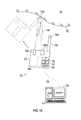
- FIG. 10is top schematic view of a scanner according to an embodiment
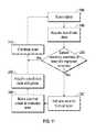
- FIG. 11is a flow chart showing a method of operating the scanner of FIG. 10 ;
- FIG. 12is a flow chart showing a diagnostic method according to an embodiment.
- Embodiments of the present inventionprovide advantages increasing the reliability and accuracy of three-dimensional coordinates of a data point cloud acquired by a scanner.
- Embodiments of the inventionprovide advantages in detecting anomalies in acquired data and automatically adjusting the operation of the scanner to acquire the desired results.
- Embodiments of the inventionprovide advantages in detecting anomalies in the acquired data and providing indication to the operator of areas where additional data acquisition is needed.
- Still further embodiments of the inventionprovide advantages in detecting anomalies in the acquired data and providing indication to the operator where additional data acquisition may be acquired with a remote probe.
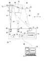
- a scanner 20 shown in FIG. 1has a housing 22 that includes a first camera 24 , a second camera 26 and a projector 28 .
- the projector 28emits light 30 onto a surface 32 of an object 34 .
- the projector 28uses a visible light source that illuminates a pattern generator.
- the visible light sourcemay be a laser, a superluminescent diode, an incandescent light, a Xenon lamp, a light emitting diode (LED), or other light emitting device for example.
- the pattern generatoris a chrome-on-glass slide having a structured light pattern etched thereon.
- the slidemay have a single pattern or multiple patterns that move in and out of position as needed.
- the slidemay be manually or automatically installed in the operating position.
- the source patternmay be light reflected off or transmitted by a digital micro-mirror device (DMD) such as a digital light projector (DLP) manufactured by Texas Instruments Corporation, a liquid crystal device (LCD), a liquid crystal on silicon (LCOS) device, or a similar device used in transmission mode rather than reflection mode.
- DMDdigital micro-mirror device
- DLPdigital light projector
- LCDliquid crystal device
- LCOSliquid crystal on silicon
- the projector 28may further include a lens system 36 that alters the outgoing light to cover the desired area.
- the projector 28is configurable to emit a structured light over an area 37 .
- structured lightrefers to a two-dimensional pattern of light projected onto an area of an object that conveys information which may be used to determine coordinates of points on the object.
- a structured light patternwill contain at least three non-collinear pattern elements disposed within the area. Each of the three non-collinear pattern elements conveys information which may be used to determine the point coordinates.
- a projectoris provided that is configurable to project both an area pattern as well as a line pattern.
- the projectoris a digital micromirror device (DMD), which is configured to switch back and forth between the two.
- the DMD projectormay also sweep a line or to sweep a point in a raster pattern.
- a coded light patternis one in which the three dimensional coordinates of an illuminated surface of the object are found by acquiring a single image. With a coded light pattern, it is possible to obtain and register point cloud data while the projecting device is moving relative to the object.
- One type of coded light patterncontains a set of elements (e.g. geometric shapes) arranged in lines where at least three of the elements are non-collinear. Such pattern elements are recognizable because of their arrangement.
- an uncoded structured light pattern as used hereinis a pattern that does not allow measurement through a single pattern.
- a series of uncoded light patternsmay be projected and imaged sequentially. For this case, it is usually necessary to hold the projector fixed relative to the object.
- the scanner 20may use either coded or uncoded structured light patterns.
- the structured light patternmay include the patterns disclosed in the journal article “DLP-Based Structured Light 3D Imaging Technologies and Applications” by Jason Geng published in the Proceedings of SPIE, Vol. 7932, which is incorporated herein by reference.
- the projector 28transmits a pattern formed a swept line of light or a swept point of light. Swept lines and points of light provide advantages over areas of light in identifying some types of anomalies such as multipath interference. Sweeping the line automatically while the scanner is held stationary also has advantages in providing a more uniform sampling of surface points.
- the first camera 24includes a photosensitive sensor 44 which generates a digital image/representation of the area 48 within the sensor's field of view.
- the sensormay be charged-coupled device (CCD) type sensor or a complementary metal-oxide-semiconductor (CMOS) type sensor for example having an array of pixels.
- CMOScomplementary metal-oxide-semiconductor
- the first camera 24may further include other components, such as but not limited to lens 46 and other optical devices for example.
- the lens 46has an associated first focal length.
- the sensor 44 and lens 46cooperate to define a first field of view “X”. In the exemplary embodiment, the first field of view “X” is 16 degrees (0.28 inch per inch).
- the second camera 26includes a photosensitive sensor 38 which generates a digital image/representation of the area 40 within the sensor's field of view.
- the sensormay be charged-coupled device (CCD) type sensor or a complementary metal-oxide-semiconductor (CMOS) type sensor for example having an array of pixels.
- CMOScomplementary metal-oxide-semiconductor
- the second camera 26may further include other components, such as but not limited to lens 42 and other optical devices for example.
- the lens 42has an associated second focal length, the second focal length being different than the first focal length.
- the sensor 38 and lens 42cooperate to define a second field of view “Y”.
- the second field of view “Y”is 50 degrees (0.85 inch per inch).
- the second field of view Yis larger than the first field of view X.
- the area 40is larger than the area 48 . It should be appreciated that a larger field of view allows acquired a given region of the object surface 32 to be measured faster; however, if the photosensitive arrays 44 and 38 have the same number of pixels, a smaller field of view will provide higher resolution.
- the projector 28 and the first camera 24are arranged in a fixed relationship at an angle such that the sensor 44 may receive light reflected from the surface of the object 34 .
- the projector 28 and the second camera 26are arranged in a fixed relationship at an angle such that the sensor 38 may receive light reflected from the surface 32 of object 34 . Since the projector 28 , first camera 24 and second camera 26 have fixed geometric relationships, the distance and the coordinates of points on the surface may be determined by their trigonometric relationships.
- the fields-of-view (FOVs) of the cameras 24 and 26are shown not to overlap in FIG. 1 , the FOVs may partially overlap or totally overlap.
- the projector 28 and cameras 24 , 26are electrically coupled to a controller 50 disposed within the housing 22 .
- the controller 50may include one or more microprocessors, digital signal processors, memory and signal conditioning circuits.
- the scanner 20may further include actuators (not shown) which may be manually activated by the operator to initiate operation and data capture by the scanner 20 .
- the image processing to determine the X, Y, Z coordinate data of the point cloud representing the surface 32 of object 34is performed by the controller 50 .
- the coordinate datamay be stored locally such as in a volatile or nonvolatile memory 54 for example.
- the memorymay be removable, such as a flash drive or a memory card for example.
- the scanner 20has a communications circuit 52 that allows the scanner 20 to transmit the coordinate data to a remote processing system 56 .
- the communications medium 58 between the scanner 20 and the remote processing system 56may be wired (e.g. Ethernet) or wireless (e.g. Bluetooth, IEEE 802.11).
- the coordinate datais determined by the remote processing system 56 based on acquired images transmitted by the scanner 20 over the communications medium 58 .
- a relative motionis possible between the object surface 32 and the scanner 20 , as indicated by the bidirectional arrow 47 .
- the scanneris a handheld scanner and the object 34 is fixed.
- Relative motionis provided by moving the scanner over the object surface.
- the scanneris attached to a robotic end effector.
- Relative motionis provided by the robot as it moves the scanner over the object surface.
- either the scanner 20 or the object 34is attached to a moving mechanical mechanism, for example, a gantry coordinate measurement machine or an articulated arm CMM.
- Relative motionis provided by the moving mechanical mechanism as it moves the scanner 20 over the object surface.
- motionis provided by the action of an operator and in other embodiments, motion is provided by a mechanism that is under computer control.
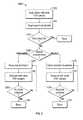
- the projector 28first emits a structured light pattern onto the area 37 of surface 32 of the object 34 .
- the light 30 from projector 28is reflected from the surface 32 as reflected light 62 received by the second camera 26 .
- the three-dimensional profile of the surface 32affects the image of the pattern captured by the photosensitive array 38 within the second camera 26 .
- the controller 50 or the remote processing system 56determines a one to one correspondence between the pixels of the photosensitive array 38 and pattern of light emitted by the projector 28 .
- triangulation principalsare used to determine the three-dimensional coordinates of points on the surface 32 .
- This acquisition of three-dimensional coordinate data(point cloud data) is shown in block 1264 .
- a point cloudmay be created of the entire object 34 .
- the controller 50 or remote processing system 56may detect an undesirable condition or problem in the point cloud data, as shown in block 1266 .
- the detected problemmay be an error in or absence of point cloud data in a particular area for example. This error in or absence of data may be caused by too little or too much light reflected from that area. Too little or too much reflected light may result from a difference in reflectance over the object surface, for example, as a result of high or variable angles of incidence of the light 30 on the object surface 32 or as a result of low reflectance (black or transparent) materials or shiny surfaces. Certain points on the object may be angled in such as way as to produce a very bright specular reflectance known as a glint.
- Another possible reason for an error in or absence of point cloud datais a lack of resolution in regions having fine features, sharp edges, or rapid changes in depth. Such lack of resolution may be the result of a hole, for example.
- Multipath interferenceoccurs when the light reaching the point on the surface 32 does not come only from the ray of light from the projector 28 but in addition, from secondary light is reflected off another portion of the surface 32 . Such secondary light may compromise the pattern of light received by the photosensitive array 38 , 44 , thereby preventing accurate determination of three-dimensional coordinates of the point.
- the controllerdetermines that the point cloud is all right in block 1266 , the procedure is finished. Otherwise, a determination is made in block 1268 of whether the scanner is used in a manual or automated mode. If the mode is manual, the operator is directed in block 1270 to move the scanner into the desired position.
- indicator lights on the scanner bodyindicate the desired direction of movement.
- a lightis projected onto the surface indicating the direction over which the operator is to move.
- a color of the projected lightmay indicate whether the scanner is too close or too far from the object.
- an indicationis made on display of the region to which the operator is to project the light.
- Such a displaymay be a graphical representation of point cloud data, a CAD model, or a combination of the two. The display may be presented on a computer monitor or on a display built into the scanning device.
- a method of determining the approximate position of the scanneris desired.
- the scannermay be attached to an articulated arm CMM that uses angular encoders in its joints to determine the position and orientation of the scanner attached to its end.
- the scannerincludes inertial sensors placed within the device. Inertial sensors may include gyroscopes, accelerometers, and magnetometers, for example.
- Another method of determining the approximate position of the scanneris to illuminate photogrammetric dots placed on or around the object as marker points. In this way, the wide FOV camera in the scanner can determine the approximate position of the scanner in relation to the object.
- a CAD model on a computer screenindicates the regions where additional measurements are desired, and the operator moves the scanner according by matching the features on the object to the features on the scanner.
- the operatormay be given rapid feedback whether the desired regions of the part have been measured.
- the resolution of the resulting three-dimensional coordinatesis improved and better capability is provided to characterize features such as holes and edges.
- the projector 28may illuminate a relatively smaller region. This has advantages in eliminating multipath interference since there is relatively fewer illuminated points on the object that can reflect light back onto the object. Having a smaller illuminated region may also make it easier to control exposure to obtain the optimum amount of light for a given reflectance and angle of incidence of the object under test.
- the procedureends at block 1276 ; otherwise it continues.
- the automated mechanismmoves the scanner into the desired position.
- the automated mechanismwill have sensors to provide information about the relative position of the scanner and object under test.
- the automated mechanismis a robot
- angular transducers within the robot jointsprovide information about the position and orientation of the robot end effector used to hold the scanner.
- linear encoders or a variety of other sensorsmay provide information on the relative position of the object and the scanner.
- the projector 28changes the structured light pattern when the scanner switches from acquiring data with the second camera 26 to the first camera 24 .
- the same structured light patternis used with both cameras 24 , 26 .
- the projector 28emits a pattern formed by a swept line or point when the data is acquired by the first camera 24 . After acquiring data with the first camera 24 , the process continues scanning using the second camera 26 . This process continues until the operator has either scanned the desired area of the part.
- FIG. 2it should be appreciated that while the process of FIG. 2 is shown as a linear or sequential process, in other embodiments one or more of the steps shown may be executed in parallel.
- the method shown in FIG. 2the method involved measuring the entire object first and then carrying out further detailed measurements according to an assessment of the acquired point cloud data.
- An alternative using the scanner 20is to begin by measuring detailed or critical regions using the camera 24 having the small FOV.
- the first coordinate acquisition system 76includes a first projector 80 and a first camera 82 .
- the projector 80emits light 84 onto a surface 32 of an object 34 .
- the projector 80uses a visible light source that illuminates a pattern generator.
- the visible light sourcemay be a laser, a superluminescent diode, an incandescent light, a light emitting diode (LED), or other light emitting device.
- the pattern generatoris a chrome-on-glass slide having a structured light pattern etched thereon.
- the slidemay have a single pattern or multiple patterns that move in and out of position as needed.
- the slidemay be manually or automatically installed in the operating position.
- the source patternmay be light reflected off or transmitted by a digital micro-mirror device (DMD) such as a digital light projector (DLP) manufactured by Texas Instruments Corporation, a liquid crystal device (LCD), a liquid crystal on silicon (LCOS) device, or a similar device used in transmission mode rather than reflection mode.
- DMDdigital micro-mirror device
- DLPdigital light projector
- LCDliquid crystal device
- LCOSliquid crystal on silicon
- the projector 80may further include a lens system 86 that alters the outgoing light to have the desired focal characteristics.
- the first camera 82includes a photosensitive array sensor 88 which generates a digital image/representation of the area 90 within the sensor's field of view.
- the sensormay be charged-coupled device (CCD) type sensor or a complementary metal-oxide-semiconductor (CMOS) type sensor for example having an array of pixels.
- CMOScomplementary metal-oxide-semiconductor
- the first camera 82may further include other components, such as but not limited to lens 92 and other optical devices for example.
- the first projector 80 and first camera 82are arranged at an angle in a fixed relationship such that the first camera 82 may detect light 85 from the first projector 80 reflected off of the surface 32 of object 34 .
- first camera 92 and first projector 80are arranged in a fixed relationship, the trigonometric principals discussed above may be used to determine coordinates of points on the surface 32 within the area 90 .
- FIG. 3is depicted as having the first camera 82 near to the first projector 80 , it should be appreciated that the camera could be placed nearer the other side of the housing 22 . By spacing the first camera 82 and first projector 80 farther apart, accuracy of 3D measurement is expected to improve.
- the second coordinate acquisition system 78includes a second projector 94 and a second camera 96 .
- the projector 94has a light source that may comprise a laser, a light emitting diode (LED), a superluminescent diode (SLED), a Xenon bulb, or some other suitable type of light source.
- a lens 98is used to focus the light received from the laser light source into a line of light 100 and may comprise one or more cylindrical lenses, or lenses of a variety of other shapes.
- the lensis also referred to herein as a “lens system” because it may include one or more individual lenses or a collection of lenses.
- the line of lightis substantially straight, i.e., the maximum deviation from a line will be less than about 1% of its length.
- One type of lens that may be utilized by an embodimentis a rod lens.
- Rod lensesare typically in the shape of a full cylinder made of glass or plastic polished on the circumference and ground on both ends. Such lenses convert collimated light passing through the diameter of the rod into a line.
- Another type of lens that may be usedis a cylindrical lens.
- a cylindrical lensis a lens that has the shape of a partial cylinder. For example, one surface of a cylindrical lens may be flat, while the opposing surface is cylindrical in form.
- the projector 94generates a two-dimensional pattern of light that covers an area of the surface 32 .
- the resulting coordinate acquisition system 78is then referred to as a structured light scanner.
- the second camera 96includes a sensor 102 such as a charge-coupled device (CCD) type sensor or a complementary metal-oxide-semiconductor (CMOS) type sensor for example.
- the second camera 96may further include other components, such as but not limited to lens 104 and other optical devices for example.
- the second projector 94 and second camera 96are arranged at an angle such that the second camera 96 may detect light 106 from the second projector 94 reflected off of the object 34 . It should be appreciated that since the second projector 94 and the second camera 96 are arranged in a fixed relationship, the trigonometric principles discussed above may be used to determine coordinates of points on the surface 32 on the line formed by light 100 . It should also be appreciated that the camera 96 and the projector 94 may be located on opposite sides of the housing 22 to increase 3D measurement accuracy.
- the second coordinate acquisition systemis configured to project a variety of patterns, which may include not only a fixed line of light but also a swept line of light, a swept point of light, a coded pattern of light (covering an area), or a sequential pattern of light (covering an area).
- a variety of projection patternmay include not only a fixed line of light but also a swept line of light, a swept point of light, a coded pattern of light (covering an area), or a sequential pattern of light (covering an area).
- Each type of projection patternhas different advantages such as speed, accuracy, and immunity to multipath interference.
- the distance from the second coordinate acquisition system 78 and the object surface 32is different than the distance from the first coordinate acquisition system 76 and the object surface 32 .
- the camera 96may be positioned closer to the object 32 than the camera 88 . In this way, the resolution and accuracy of the second coordinate acquisition system 78 can be improved relative to that of the first coordinate acquisition system 76 . In many cases, it is helpful to quickly scan a relatively large and smooth object with a lower resolution system 76 and then scan details including edges and holes with a higher resolution system 78 .
- a scanner 20may be used in a manual mode or in an automated mode.
- a manual modean operator is prompted to move the scanner nearer or farther from the object surface according to the acquisition system that is being used.
- the scanner 20may project a beam or pattern of light indicating to the operator the direction in which the scanner is to be moved.
- indicator lights on the devicemay indicate the direction in which the scanner should be moved.
- the scanner 20 or object 34may be automatically moved relative to one another according to the measurement requirements.
- the first coordinate acquisition system 76 and the second coordinate acquisition system 78are electrically coupled to a controller 50 disposed within the housing 22 .
- the controller 50may include one or more microprocessors, digital signal processors, memory and signal conditioning circuits.
- the scanner 20may further include actuators (not shown) which may be manually activated by the operator to initiate operation and data capture by the scanner 20 .
- the image processing to determine the X, Y, Z coordinate data of the point cloud representing the surface 32 of object 34is performed by the controller 50 .
- the coordinate datamay be stored locally such as in a volatile or nonvolatile memory 54 for example.
- the memorymay be removable, such as a flash drive or a memory card for example.
- the scanner 20has a communications circuit 52 that allows the scanner 20 to transmit the coordinate data to a remote processing system 56 .
- the communications medium 58 between the scanner 20 and the remote processing system 56may be wired (e.g. Ethernet) or wireless (e.g. Bluetooth, IEEE 802.11).
- the coordinate datais determined by the remote processing system 56 and the scanner 20 transmits acquired images on the communications medium 58 .
- the first projector 80 of the first coordinate acquisition system 76 of scanner 20emits a structured light pattern onto the area 90 of surface 32 of the object 34 .
- the light 84 from projector 80is reflected from the surface 32 and the reflected light 85 is received by the first camera 82 .
- the variations in the surface profile of the surface 32create distortions in the imaged pattern of light received by the first photosensitive array 88 .
- the controller 50 or the remote processing system 56determines a one to one correspondence between points on the surface 32 and the pixels in the photosensitive array 88 .
- Thisenables triangulation principles discussed above to be used in block 1404 to obtain point cloud data, which is to say to determine X, Y, Z coordinates of points on the surface 32 .
- point cloud dataBy moving the scanner 20 relative to the surface 32 , a point cloud may be created of the entire object 34 .
- the controller 50 or remote processing system 56determines whether the point cloud data possesses the desired data quality attributes or has a potential problem. The types of problems that may occur were discussed hereinabove in reference to FIG. 2 and this discussion is not repeated here. If the controller determines that the point cloud has the desired data quality attributes in block 1406 , the procedure is finished. Otherwise, a determination is made in block 1408 of whether the scanner is used in a manual or automated mode. If the mode is manual, the operator is directed in block 1410 to move the scanner to the desired position.
- methodsmay include attachment of the scanner 20 to an articulated arm CMM, use of inertial sensors within the scanner 20 , illumination of photogrammetric dots, or matching of features to a displayed image.
- the automated mechanismmoves the scanner into the desired position.
- an automated mechanismwill have sensors to provide information about the relative position of the scanner and object under test.
- angular transducers within the robot jointsprovide information about the position and orientation of the robot end effector used to hold the scanner.
- linear encoders or a variety of other sensorsmay provide information on the relative position of the object and the scanner.
- FIG. 4it should be appreciated that while the process of FIG. 4 is shown as a linear or sequential process, in other embodiments one or more of the steps shown may be executed in parallel.
- the method shown in FIG. 4the method involved measuring the entire object first and then carrying out further detailed measurements according to an assessment of the acquired point cloud data.
- An alternative using scanner 20is to begin by measuring detailed or critical regions using the second coordinate acquisition system 78 .
- An errormay occur in making scanner measurements as a result of multipath interference.
- the origin of multipath interferenceis now discussed, and a first method for eliminating or reducing multipath interference is described.
- the case of multipath interferenceoccurs when the some of the light that strikes the object surface is first scattered off another surface of the object before returning to the camera. For the point on the object that receives this scattered light, the light sent to the photosensitive array then corresponds not only to the light directly projected from the projector but also to the light sent to a different point on the projector and scattered off the object.
- the result of multipath interferenceespecially for the case of scanners that project two-dimensional (structured) light, may be to cause the distance calculated from the projector to the object surface at that point to be inaccurate.
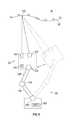
- a scanner 4570projects a line of light 4525 onto the surface 4510 A of an object.
- the line of light 4525is perpendicular to the plane of the paper.
- the rows of a photosensitive arrayare parallel to the plane of the paper and the columns are perpendicular to the plane of the paper.
- Each rowrepresents one point on the projected line 4525 in the direction perpendicular to the plane of the paper.
- the distance from the projector to the object for that point on the lineis found by first calculating the centroid for each row. For the surface point 4526 , the centroid on the photosensitive array 4541 is represented by the point 4546 .
- the position 4546 of the centroid on the photosensitive arraycan be used to calculate the distance from the camera perspective center 4544 to the object point 4526 . This calculation is based on trigonometric relationships according to the principles of triangulation. To perform these calculations, the baseline distance D from the camera perspective center 4544 to the projector perspective center 4523 is required. In addition, knowledge of the relative orientation of the projector system 4520 to the camera system 4540 is required.
- a secondary reflection from a point such as 4527is not usually as obvious as for light projected onto a line and hence is more likely to create an error in the measured 3D surface coordinates.
- the display element 4521might be a digital micro mechanical mirror (DMM) such as a digital light projector (DLP).
- DMMdigital micro mechanical mirror
- DLPdigital light projector
- Such devicescontain multiple small mirrors that are rapidly adjustable by means of an electrical signal to rapidly adjust a pattern of illumination.
- Other devices that can produce an electrically adjustable display patterninclude an LCD (liquid crystal display) and an LCOS (liquid crystal on silicon) display.
- a way of checking for multipath interference in a system that projects structured light over an areais to change the display to project a line of light.
- the presence of multiple centroids in a rowwill indicate that multipath interference is present.
- By sweeping the line of lightan area can be covered without requiring that the probe be moved by an operator.
- the line of lightcan be set to any desired angle by an electrically adjustable display. By changing the direction of the projected line of light, multipath interference can, in many cases, be eliminated.
- the electrically adjustable displaycan be used to sweep a point of light.
- a secondary reflectionmay be produced from a single point of light, but it is usually relatively easy to determine which of the reflected spots of light is valid.
- An electrically adjustable displaycan also be used to quickly switch between a coded and an uncoded pattern.
- a coded patternis used to make a 3D measurement based on a single frame of camera information.
- multiple patternsmay be used to obtain greater accuracy in the measured 3D coordinate values.
- electrically adjustable displayshave been used to project each of a series of patterns within a sequential pattern—for example, a series of gray scale line patterns followed by a sequence of sinusoidal patterns, each having a different phase.
- the present inventive methodprovides advantages over earlier methods in selecting those methods that identify or eliminate problems such as multipath interference and that indicate whether a single-shot pattern (for example, coded pattern) or a multiple-shot pattern is preferred to obtain the required accuracy as quickly as possible.
- a single-shot patternfor example, coded pattern
- a multiple-shot patternis preferred to obtain the required accuracy as quickly as possible.
- multipath interferenceFor the case of a line scanner, there is often a way to determine the presence of multipath interference.
- the light reflected by a point on the object surfaceis imaged in a single row onto a region of contiguous pixels. If there are two or more regions of a row receive a significant amount of light, multipath interference is indicated.
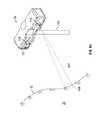
- FIG. 5AAn example of such a multipath interference condition and the resulting extra region of illumination on the photosensitive array are shown in FIG. 5A .
- the surface 4510 Anow has a greater curvature near the point of intersection 4526 .
- the surface normal at the point of intersectionis the line 4528 , and the angle of incidence is 4531 .
- the direction of the reflected line of light 4529is found from the angle of reflection 4532 , which is equal to the angle of incidence.
- the line of light 4529actually represents an overall direction for light that scatters over a range of angles.
- the center of the scattered lightstrikes the surface 4510 A at the point 4527 , which is imaged by the lens 4544 at the point 4548 on the photosensitive array.
- the unexpectedly high amount of light received in the vicinity of point 4548indicates that multipath interference is probably present.
- the main concern with multipath interferenceis not for the case shown in FIG. 5A , where the two spots 4546 and 4527 are separated by a considerable distance and can be analyzed separately but rather for the case in which the two spots overlap or smear together.
- a line scannerFor a projected line of light, in many cases, it is possible to eliminate multipath interference by changing the direction of the line.
- One possibilityis to make a line scanner using a projector having inherent two-dimensional capability, thereby enabling the line to be swept or to be automatically rotated to different directions.
- An example of such a projectoris one that makes use of a digital micromirror (DMD), as discussed hereinabove.
- DMDdigital micromirror
- a measurement systemcould be automatically configured to switch to a measurement method using a swept line of light.
- Another method to reduce, minimize or eliminate multipath interferenceis to sweep a point of light, rather than a line of light or an area of light, over those regions for which multipath interference has been indicated. By illuminating a single point of light, any light scattered from a secondary reflection can usually be readily identified.
- a measurementis first performed by projecting a coded pattern of light onto an object in a single shot.
- the three-dimensional coordinates of the surfaceare determined using the collected data, and the results analyzed to determine whether some regions have holes, edges, or features that require more detailed analysis.
- Such detailed analysismight be performed for example by using the narrow FOV camera 24 in FIG. 1 or the high resolution scanner system 78 in FIG. 3 .
- the coordinatesare also analyzed to determine the approximate distance to the target, thereby providing a starting distance for a more accurate measurement method such as a method that sequentially projects sinusoidal phase-shifted patterns of light onto a surface, as discussed hereinabove.
- Obtaining a starting distance for each point on the surface using the coded light patterneliminates the need to obtain this information by vary the pitch in multiple sinusoidal phase-shifted scans, thereby saving considerable time.
- the process 211starts in block 212 by scanning an object, such as object 34 , with a scanner 20 .
- the scanner 20may be a scanner such as those described in the embodiments of FIG. 1, 3, 5 and FIG. 7 for example having at least one projector and a camera.
- the scanner 20projects a first light pattern onto the object in block 212 .
- this first light patternis a coded structured light pattern.
- the process 211acquires and determines the three-dimensional coordinate data in block 214 .
- the coordinate datais analyzed in query block 216 to determine if there are any anomalies, such as the aforementioned multipath interference, low resolution around an element, or an absence of data due to surface angles or surface reflectance changes.
- the process 211proceeds to block 218 where the light pattern emitted by the projector is changed to a second light pattern.
- the second light patternis a swept line of light.
- the process 211proceeds to block 220 where the three-dimensional coordinate data is acquired and determined for the area where the anomaly was detected.
- the process 211loops back to query block 216 where it is determined if the anomaly has been resolved. If the query block 216 still detects an anomaly or lack or accuracy or resolution, the process loops back to block 218 and switches to a third light pattern.
- the third light patternis a sequential sinusoidal phase shift pattern. In another embodiment, the third light pattern is a swept point of light. This iterative procedure continues until the anomaly has been resolved.
- the process 211proceeds to block 222 where the emitted pattern is switched back to the first structured light pattern and the scanning process is continued.
- the process 211continues until the operator has scanned the desired area of the object.
- a problem of measuring with a tactile probemay be used.
- FIG. 6another embodiment of a scanner 20 is shown mounted to a movable apparatus 120 .
- the scanner 20has at least one projector 122 and at least one camera 124 that are arranged in a fixed geometric relationship such that trigonometric principles may be used to determine the three-dimensional coordinates of points on the surface 32 .
- the scanner 20may be the same scanner as described in reference to FIG. 1 or FIG. 3 for example. In one embodiment, the scanner is the same as the scanner of FIG. 10 having a tactile probe.
- the scanner used in the embodiment of FIG. 6may be any scanner such as a structured light or line scanner, for example, a scanner disclosed in commonly owned U.S. Pat. No.
- the scanner used in the embodiment of FIG. 6is a structured light scanner that projects light over an area on an object.
- the moveable apparatus 120is a robotic apparatus that provides automated movements by means of arm segments 126 , 128 that are connected by pivot and swivel joints 130 to allow the arm segments 126 , 128 to be moved, resulting in the scanner 20 moving from a first position to a second position (as indicated in dashed line in FIG. 6 ).
- the moveable apparatus 120may include actuators, such as motors (not shown), for example, that are coupled to the arm segments 126 , 128 to move the arm segments 126 , 128 from the first position to the second position.
- a movable apparatus 120 having articulated armsis for exemplary purposes and the claimed invention should not be so limited.
- the scanner 20may be mounted to a movable apparatus that moves the scanner 20 via rails, wheels, tracks, belts or cables or a combination of the foregoing for example.
- the robothas a different number of arm segments.
- the movable apparatusis an articulated arm coordinate measurement machine (AACMM) such as that described in commonly owned U.S. patent application Ser. No. 13/491,176 filed on Jan. 20, 2010.
- AACMMarticulated arm coordinate measurement machine
- the movement of the scanner 20 from the first position to the second positionmay involve the operator manually moving the arm segments 126 , 128 .
- the moveable apparatus 120further includes a controller 132 that is configured to energize the actuators to move the arm segments 126 , 128 .
- the controller 132communicates with a controller 134 .
- this arrangementallows the controller 132 to move the scanner 20 in response to an anomaly in the acquired data. It should be appreciated that the controllers 132 , 134 may be incorporated into a single processing unit or the functionality may be distributed among several processing units.
- a feature being measuredmay benefit from a desired direction of the scanner. For example, measurement of the diameter of a hole may be improved by orienting the scanner camera 124 to be approximately perpendicular to the hole.
- a scannermay be positioned so as to reduce or minimize the possibility of multipath interference.
- Such an analysismay be based on a CAD model available as a part of the diagnostic procedure or it may be based on data collected by the scanner in an initial position prior to a secondary movement of the scanner 20 by the apparatus 120 .
- the processcontinues to block 144 where the movable apparatus 120 moves the position of the scanner 20 , such as from the first position to the second position, and rescans the area of interest in block 146 to acquire three-dimensional coordinate data.
- the processloops back to query block 140 where it is determined whether there is still an anomaly in the coordinate data or if an improvement measurement accuracy is desired. If these cases, the scanner 20 is moved again and the process continues until the measurement results achieve a desired level. Once the coordinate data is obtained, the process proceeds from query block 140 to block 148 where the scanning process continues until the desired area has been scanned.
- the movement of the scanner from the first position to the second positionmay be arranged to contact the areas of interest with the tactile probe. Since the position of the scanner, and thus the tactile probe, may be determined from the position and orientation of the arm segments 126 , 128 the three-dimensional coordinates of the point on the surface 32 may be determined.
- measurement results obtained by the scanner 20 of FIGS. 8A, 8Bmay be corrupted by multipath interference.
- measurement resultsmay not provide the desired resolution or accuracy to properly measure some characteristics of the surface 32 , especially edges, holes, or intricate features.
- the scanner 20includes a projector 156 and cameras 154 , 155 arranged on an angle relative to the projector 156 such that light emitted by the projector 156 is reflected off of the surface 32 and received by one or both of the cameras 154 , 155 .
- the projector 156 and cameras 154 , 156are arranged in a fixed geometric relationship so that trigonometric principles may be used to determine the three-dimensional coordinates of points on the surface 32 .
- the projector 156is configured to emit a visible light 157 onto an area of interest 159 on the surface 32 of object 34 as shown in FIG. 8A .
- the three-dimensional coordinates of the illuminated area of interest 159may be confirmed using the image of the illuminated region 159 on one or both of the cameras 154 , 155 .
- the scanner 20is configured to cooperate with the remote probe 152 so that an operator may bring a probe tip 166 into contact with the object surface 132 at the illuminated region of interest 159 .
- the remote probe 152includes at least three non-collinear points of light 168 .
- the points of light 168may be spots of light produced, for example, by light emitting diodes (LED) or reflective dots of light illuminated by infrared or visible light source from the projector 156 or from another light source not depicted in FIG. 8B .
- the infrared or visible light sourcein this case may be attached to the scanner 20 or may be placed external to the scanner 20 .
- the position of the probe tip 166may be determined, thereby enabling the coordinates of the object surface 32 to be determined.
- a tactile probe used in this wayeliminates potential problems from multipath interference and also enables relatively accurate measurement of holes, edges, and detailed features.
- the probe 166is a tactile probe, which may be activated by pressing of an actuator button (not shown) on the probe, or the probe 166 may be a touch-trigger probe activated by contact with the surface 32 .
- a communications circuit(not shown) transmits a signal to the scanner 20 .
- the points of light 168are replaced with geometrical patterns of light, which may include lines or curves.
- FIG. 9a process is shown for acquiring coordinate data for points on the surface 32 of object 34 using a stationary scanner 20 of FIGS. 8A, 8B with a remote probe 152 .
- the processstarts in block 170 with the surface 32 of the object 34 being scanned.
- the processacquires and determines the three-dimensional coordinate data of the surface 32 in block 172 .
- the processdetermines in query block 174 whether there is an anomaly in the coordinate data of area 159 or whether there is a problem in accuracy or resolution of the area 159 .
- An anomalycould be invalid data that is discarded due to multipath interference for example.
- An anomalycould also be missing data due to surface reflectance or a lack of resolution around a feature such as an opening or hole for example. Details on a diagnostic procedure for detecting (identifying) multipath interference and related problems in given in reference to FIG. 12 .
- the scanner 20indicates in block 176 to the operator the coordinate data of area 159 may be acquired via the remote probe 152 .
- This area 159may be indicated by emitting a visible light 157 to illuminate the area 159 .
- the light 157is emitted by the projector 156 .
- the color of light 157may be changed to inform the operator of the type of anomaly or problem. For example, where multipath interference occurs, the light 157 may be colored red, while a low resolution may be colored green.
- the areamay further be indicated on a display having a graphical representation (e.g. a CAD model) of the object.
- the processthen proceeds to block 178 to acquire an image of the remote probe 152 when the sensor 166 touches the surface 32 .
- the points of light 168which may be LEDs or reflective targets, for example, are received by one of the cameras 154 , 155 .
- the scanner 20determines in block 180 the three-dimensional coordinates of the probe center from which three-dimensional coordinates of the object surface 32 are determined in block 180 . Once the points in the area 159 where the anomaly was detected have been acquired, the process may proceed to continue the scan of the object 34 in block 182 until the desired areas have been scanned.
- the housing 22may include a handle 186 that allows the operator to hold the scanner 20 during operation.
- the housing 22includes a projector 188 and a camera 190 arranged on an angle relative to each other such that the light 192 emitted by the projector is reflected off of the surface 32 and received by the camera 190 .
- the scanner 20 of FIG. 10operates in a manner substantially similar to the embodiments of FIG. 1 and FIG. 3 and acquires three-dimensional coordinate data of points on the surface 32 using trigonometric principles.
- the scanner 20further includes an integral probe member 184 .
- the probe member 184includes a sensor 194 on one end.
- the sensor 194is a tactile probe that may respond to pressing of an actuator button (not shown) by an operator or it may be a touch trigger probe that responds to contact with the surface 32 , for example.
- the probe member 184allows the operator to acquire coordinates of points on the surface 32 by contacting the sensor 194 to the surface 32 .
- the projector 188 , camera 190 and actuator circuit for the sensor 194are electrically coupled to a controller 50 disposed within the housing 22 .
- the controller 50may include one or more microprocessors, digital signal processors, memory and signal conditioning circuits.
- the scanner 20may further include actuators (not shown), such as on the handle 186 for example, which may be manually activated by the operator to initiate operation and data capture by the scanner 20 .
- the image processing to determine the X, Y, Z coordinate data of the point cloud representing the surface 32 of object 34is performed by the controller 50 .
- the coordinate datamay be stored locally such as in a volatile or nonvolatile memory 54 for example.
- the memorymay be removable, such as a flash drive or a memory card for example.
- the scanner 20has a communications circuit 52 that allows the scanner 20 to transmit the coordinate data to a remote processing system 56 .
- the communications medium 58 between the scanner 20 and the remote processing system 56may be wired (e.g. Ethernet) or wireless (e.g. Bluetooth, IEEE 802.11).
- the coordinate datais determined by the remote processing system 56 and the scanner 20 transmits acquired images on the communications medium 58 .
- the processbegins in block 196 with the operator scanning the surface 32 of the object 34 by manually moving the scanner 20 .
- the three-dimensional coordinatesare determined and acquired in block 198 .
- the area 204may be indicated by projecting a visible light 192 with the projector 188 onto the surface 32 . In one embodiment, the light 192 is colored to notify the operator of the type of anomaly detected.
- the sensor 194contacts the surface 32 .
- the position and orientation (to six degrees of freedom) of the scanner 20 in the second positionmay be determined using well known best-fit methods based on images acquired by the camera 190 . Since the dimensions and arrangement of the sensor 194 are known in relation to the mechanical structure of the scanner 20 , the three-dimensional coordinate data of the points in area 204 may be determined in block 208 .
- a general approachmay be used to evaluate not only multipath interference but also quality in general, including resolution and effect of material type, surface quality, and geometry.
- a method 4600may be carried out automatically under computer control.
- a step 4602is to determine whether information on three-dimensional coordinates of an object under test are available.
- a first type of three-dimensional informationis CAD data.
- CAD datausually indicates nominal dimensions of an object under test.
- a second type of three-dimensional informationis measured three-dimensional data—for example, data previously measured with a scanner or other device.
- the step 4602may include a further step of aligning the frame of reference of the coordinate measurement device, for example, laser tracker or six-DOF scanner accessory, with the frame of reference of the object. In an embodiment, this is done by measuring at least three points on the surface of the object with the laser tracker.
- step 4604the computer or processor is used to calculate the susceptibility of the object measurement to multipath interference. In an embodiment, this is done by projecting each ray of light emitted by the scanner projector, and calculating the angle or reflection for each case.
- the computer or softwareidentifies each region of the object surface that is susceptible to error as a result of multipath interference.
- the step 4604may also carry out an analysis of the susceptibility to multipath error for a variety of positions of the six-DOF probe relative to the object under test.
- multipath interferencemay be avoided or minimized by selecting a suitable position and orientation of the six-DOF probe relative to the object under test, as described hereinabove. If the answer to the question posed in step 4602 is that three-dimensional information is not available, then a step 4606 is to measure the three-dimensional coordinates of the object surface using any desired or preferred measurement method. Following the calculation of multipath interference, a step 4608 may be carried out to evaluate other aspects of expected scan quality. One such quality factor is whether the resolution of the scan is sufficient for the features of the object under test. For example, if the resolution of a device is 3 mm, and there are sub-millimeter features for which valid scan data is desired, then these problem regions of the object should be noted for later corrective action.
- Another quality factor related partly to resolutionis the ability to measure edges of the object and edges of holes. Knowledge of scanner performance will enable a determination of whether the scanner resolution is good enough for given edges. Another quality factor is the amount of light expected to be returned from a given feature. Little if any light may be expected to be returned to the scanner from inside a small hole, for example, or from a glancing angle. Also, little light may be expected from certain kinds and colors of materials. Certain types of materials may have a large depth of penetration for the light from the scanner, and in this case good measurement results would not be expected. In some cases, an automatic program may ask for user supplementary information.
- the step 4608may include a further step of obtaining material characteristics for the object under test.
- step 4610is to decide whether further diagnostic procedures should be carried out.
- a first example of a possible diagnostic procedureis the step 4612 of projecting a stripe at a preferred angle to note whether multipath interference is observed. The general indications of multipath interference for a projected line stripe were discussed hereinabove with reference to FIG. 5 .
- Another example of a diagnostic stepis step 4614 , which is to project a collection of lines aligned in the direction of epipolar lines on the source pattern of light, for example, the source pattern of light 30 from projector 36 in FIG. 1 .
- the step 4616is to select a combination of preferred actions based on the analyses and diagnostic procedure performed. If speed in a measurement is particularly important, a step 4618 of measuring using a 2D (structured) pattern of coded light may be preferred. If greater accuracy is more important, then a step 4620 of measuring using a 2D (structured) pattern of coded light using sequential patterns, for example, a sequence of sinusoidal patterns of varying phase and pitch, may be preferred. If the method 4618 or 4620 is selected, then it may be desirable to also select a step 4628 , which is to reposition the scanner, in other words to adjust the position and orientation of the scanner to the position that minimizes multipath interference and specular reflections (glints) as provided by the analysis of step 4604 .
- a step 4628is to reposition the scanner, in other words to adjust the position and orientation of the scanner to the position that minimizes multipath interference and specular reflections (glints) as provided by the analysis of step 4604 .
- Such indicationsmay be provided to a user by illuminating problem regions with light from the scanner projector or by displaying such regions on a monitor display.
- the next steps in the measurement proceduremay be automatically selected by a computer or processor. If the preferred scanner position does not eliminate multipath interference and glints, several options are available. In some cases, the measurement can be repeated with the scanner repositioned and the valid measurement results combined. In other cases, alternative measurement steps may be added to the procedure or performed instead of using structured light. As discussed previously, a step 4622 of scanning a stripe of light provides a convenient way of obtaining information over an area with reduced chance of having a problem from multipath interference.
- a step 4624 of sweeping a small spot of light over a region of interestfurther reduces the chance of problems from multipath interference.
- a step of measuring a region of an object surface with a tactile probeeliminates the possibility of multipath interference.
- a tactile probeprovides a known resolution based on the size of the probe tip, and it eliminates issues with low reflectance of light or large optical penetration depth, which might be found in some objects under test.
- the quality of the data collected in a combination of the steps 4618 - 4628may be evaluated in a step 4630 based on the data obtained from the measurements, combined with the results of the analyses carried out previously. If the quality is found to be acceptable in a step 4632 , the measurement is completed at a step 4634 . Otherwise, the analysis resumes at the step 4604 . In some cases, the 3D information may not have been as accurate as desired. In this case, repeating some of the earlier steps may be helpful.
Landscapes
- Engineering & Computer Science (AREA)
- Physics & Mathematics (AREA)
- General Physics & Mathematics (AREA)
- Radar, Positioning & Navigation (AREA)
- Remote Sensing (AREA)
- Computer Networks & Wireless Communication (AREA)
- Electromagnetism (AREA)
- Computer Vision & Pattern Recognition (AREA)
- Multimedia (AREA)
- Length Measuring Devices By Optical Means (AREA)
Abstract
Description
Claims (22)
Priority Applications (7)
| Application Number | Priority Date | Filing Date | Title |
|---|---|---|---|
| US13/932,267US9482529B2 (en) | 2011-04-15 | 2013-07-01 | Three-dimensional coordinate scanner and method of operation |
| DE112014001483.4TDE112014001483T5 (en) | 2013-03-15 | 2014-03-05 | Three-dimensional coordinate scanner and operating procedures |
| CN201480015935.5ACN105190232A (en) | 2013-03-15 | 2014-03-05 | Three-dimensional coordinate scanner and method of operation |
| JP2016500623AJP6355710B2 (en) | 2013-03-15 | 2014-03-05 | Non-contact optical three-dimensional measuring device |
| GB1518275.1AGB2527993B (en) | 2013-03-15 | 2014-03-05 | Three-Dimensional Coordinate Scanner And Method Of Operation |
| PCT/US2014/020481WO2014149702A1 (en) | 2013-03-15 | 2014-03-05 | Three-dimensional coordinate scanner and method of operation |
| US15/263,877US10119805B2 (en) | 2011-04-15 | 2016-09-13 | Three-dimensional coordinate scanner and method of operation |
Applications Claiming Priority (6)
| Application Number | Priority Date | Filing Date | Title |
|---|---|---|---|
| US201161475703P | 2011-04-15 | 2011-04-15 | |
| US201261592049P | 2012-01-30 | 2012-01-30 | |
| US13/443,956US9207309B2 (en) | 2011-04-15 | 2012-04-11 | Six degree-of-freedom laser tracker that cooperates with a remote line scanner |
| US13/443,946US9151830B2 (en) | 2011-04-15 | 2012-04-11 | Six degree-of-freedom laser tracker that cooperates with a remote structured-light scanner |
| US201361791797P | 2013-03-15 | 2013-03-15 | |
| US13/932,267US9482529B2 (en) | 2011-04-15 | 2013-07-01 | Three-dimensional coordinate scanner and method of operation |
Related Parent Applications (1)
| Application Number | Title | Priority Date | Filing Date |
|---|---|---|---|
| US13/443,946Continuation-In-PartUS9151830B2 (en) | 2011-04-15 | 2012-04-11 | Six degree-of-freedom laser tracker that cooperates with a remote structured-light scanner |
Related Child Applications (1)
| Application Number | Title | Priority Date | Filing Date |
|---|---|---|---|
| US15/263,877ContinuationUS10119805B2 (en) | 2011-04-15 | 2016-09-13 | Three-dimensional coordinate scanner and method of operation |
Publications (2)
| Publication Number | Publication Date |
|---|---|
| US20130293684A1 US20130293684A1 (en) | 2013-11-07 |
| US9482529B2true US9482529B2 (en) | 2016-11-01 |
Family
ID=49515110
Family Applications (2)
| Application Number | Title | Priority Date | Filing Date |
|---|---|---|---|
| US13/932,267Expired - Fee RelatedUS9482529B2 (en) | 2011-04-15 | 2013-07-01 | Three-dimensional coordinate scanner and method of operation |
| US15/263,877ActiveUS10119805B2 (en) | 2011-04-15 | 2016-09-13 | Three-dimensional coordinate scanner and method of operation |
Family Applications After (1)
| Application Number | Title | Priority Date | Filing Date |
|---|---|---|---|
| US15/263,877ActiveUS10119805B2 (en) | 2011-04-15 | 2016-09-13 | Three-dimensional coordinate scanner and method of operation |
Country Status (1)
| Country | Link |
|---|---|
| US (2) | US9482529B2 (en) |
Cited By (14)
| Publication number | Priority date | Publication date | Assignee | Title |
|---|---|---|---|---|
| US20140210949A1 (en)* | 2011-08-30 | 2014-07-31 | Rafael Advanced Defense Systems Ltd. | Combination of narrow-and wide-view images |
| US9858682B2 (en)* | 2012-12-14 | 2018-01-02 | Faro Technologies, Inc. | Device for optically scanning and measuring an environment |
| US20180059226A1 (en)* | 2015-06-10 | 2018-03-01 | Hewlett-Packard Development Company, L.P. | 3d scan tuning |
| US9964402B2 (en) | 2015-04-24 | 2018-05-08 | Faro Technologies, Inc. | Two-camera triangulation scanner with detachable coupling mechanism |
| US10119805B2 (en)* | 2011-04-15 | 2018-11-06 | Faro Technologies, Inc. | Three-dimensional coordinate scanner and method of operation |
| US10209059B2 (en) | 2010-04-21 | 2019-02-19 | Faro Technologies, Inc. | Method and apparatus for following an operator and locking onto a retroreflector with a laser tracker |
| US10267619B2 (en) | 2011-04-15 | 2019-04-23 | Faro Technologies, Inc. | Three-dimensional coordinate scanner and method of operation |
| US10302413B2 (en) | 2011-04-15 | 2019-05-28 | Faro Technologies, Inc. | Six degree-of-freedom laser tracker that cooperates with a remote sensor |
| US10357317B2 (en)* | 2015-07-29 | 2019-07-23 | Synaptive Medical (Barbados) Inc. | Handheld scanner for rapid registration in a medical navigation system |
| USD875573S1 (en) | 2018-09-26 | 2020-02-18 | Hexagon Metrology, Inc. | Scanning device |
| US11022434B2 (en) | 2017-11-13 | 2021-06-01 | Hexagon Metrology, Inc. | Thermal management of an optical scanning device |
| US11169268B1 (en) | 2017-12-12 | 2021-11-09 | Philip Raymond Schaefer | System and method for measuring the position of a moving object |
| WO2023139254A1 (en)* | 2022-01-24 | 2023-07-27 | Trinamix Gmbh | Enhanced material detection by stereo beam profile analysis |
| US12038507B1 (en)* | 2017-05-09 | 2024-07-16 | National Technology & Engineering Solutions Of Sandia, Llc | Systems and methods for optical measurement of cross-wind |
Families Citing this family (94)
| Publication number | Priority date | Publication date | Assignee | Title |
|---|---|---|---|---|
| US9482755B2 (en) | 2008-11-17 | 2016-11-01 | Faro Technologies, Inc. | Measurement system having air temperature compensation between a target and a laser tracker |
| US9628775B2 (en) | 2010-01-20 | 2017-04-18 | Faro Technologies, Inc. | Articulated arm coordinate measurement machine having a 2D camera and method of obtaining 3D representations |
| US9607239B2 (en) | 2010-01-20 | 2017-03-28 | Faro Technologies, Inc. | Articulated arm coordinate measurement machine having a 2D camera and method of obtaining 3D representations |
| US9879976B2 (en) | 2010-01-20 | 2018-01-30 | Faro Technologies, Inc. | Articulated arm coordinate measurement machine that uses a 2D camera to determine 3D coordinates of smoothly continuous edge features |
| US9400170B2 (en) | 2010-04-21 | 2016-07-26 | Faro Technologies, Inc. | Automatic measurement of dimensional data within an acceptance region by a laser tracker |
| US9377885B2 (en) | 2010-04-21 | 2016-06-28 | Faro Technologies, Inc. | Method and apparatus for locking onto a retroreflector with a laser tracker |
| GB2503390B (en) | 2011-03-03 | 2014-10-29 | Faro Tech Inc | Target apparatus and method |
| US9686532B2 (en) | 2011-04-15 | 2017-06-20 | Faro Technologies, Inc. | System and method of acquiring three-dimensional coordinates using multiple coordinate measurement devices |
| DE102011114674C5 (en)* | 2011-09-30 | 2020-05-28 | Steinbichler Optotechnik Gmbh | Method and device for determining the 3D coordinates of an object |
| WO2013112455A1 (en) | 2012-01-27 | 2013-08-01 | Faro Technologies, Inc. | Inspection method with barcode identification |
| US10036631B2 (en)* | 2012-05-01 | 2018-07-31 | Texas Department Of Transportation | System and method for measuring three-dimensional surface features |
| US9473760B2 (en)* | 2012-08-08 | 2016-10-18 | Makerbot Industries, Llc | Displays for three-dimensional printers |
| DE102012112322B4 (en) | 2012-12-14 | 2015-11-05 | Faro Technologies, Inc. | Method for optically scanning and measuring an environment |
| DE202012104890U1 (en) | 2012-12-14 | 2013-03-05 | Faro Technologies, Inc. | Device for optically scanning and measuring an environment |
| EP2801839B1 (en)* | 2013-05-10 | 2020-03-04 | Leica Geosystems AG | Handheld measuring aid for use with a 6-DoF laser tracker |
| US9772173B2 (en)* | 2013-06-27 | 2017-09-26 | Faro Technologies, Inc. | Method for measuring 3D coordinates of a surface with a portable articulated arm coordinate measuring machine having a camera |
| US9476695B2 (en)* | 2013-07-03 | 2016-10-25 | Faro Technologies, Inc. | Laser tracker that cooperates with a remote camera bar and coordinate measurement device |
| US9964401B2 (en)* | 2013-07-16 | 2018-05-08 | Polyrix Inc. | Inspection system for inspecting an object and inspection method for same |
| US9594250B2 (en) | 2013-12-18 | 2017-03-14 | Hexagon Metrology, Inc. | Ultra-portable coordinate measurement machine |
| US10089415B2 (en) | 2013-12-19 | 2018-10-02 | Faro Technologies, Inc. | Three-dimensional coordinate scanner and method of operation |
| JP6320051B2 (en) | 2014-01-17 | 2018-05-09 | キヤノン株式会社 | 3D shape measuring device, 3D shape measuring method |
| JP6468802B2 (en)* | 2014-01-20 | 2019-02-13 | キヤノン株式会社 | Three-dimensional measuring apparatus, three-dimensional measuring method and program |
| CA2936465C (en) | 2014-01-21 | 2020-06-09 | Vorum Research Corporation | Method and system for generating a three-dimensional scan of an object |
| DE102014207899A1 (en)* | 2014-04-28 | 2015-10-29 | Robert Bosch Gmbh | 3D fine laser scanner |
| DE102014207893A1 (en) | 2014-04-28 | 2015-10-29 | Robert Bosch Gmbh | 3D laser scanner |
| DE102014207896A1 (en)* | 2014-04-28 | 2015-10-29 | Robert Bosch Gmbh | 3D coarse laser scanner |
| US10021379B2 (en) | 2014-06-12 | 2018-07-10 | Faro Technologies, Inc. | Six degree-of-freedom triangulation scanner and camera for augmented reality |
| US9402070B2 (en) | 2014-06-12 | 2016-07-26 | Faro Technologies, Inc. | Coordinate measuring device with a six degree-of-freedom handheld probe and integrated camera for augmented reality |
| US9395174B2 (en) | 2014-06-27 | 2016-07-19 | Faro Technologies, Inc. | Determining retroreflector orientation by optimizing spatial fit |
| CN104165600B (en)* | 2014-07-03 | 2016-10-05 | 杭州鼎热科技有限公司 | A kind of wireless handheld 3D laser scanning system |
| WO2016044014A1 (en)* | 2014-09-15 | 2016-03-24 | Faro Technologies, Inc. | Articulated arm coordinate measurement machine having a 2d camera and method of obtaining 3d representations |
| ES2967886T3 (en) | 2014-09-19 | 2024-05-06 | Hexagon Metrology Inc | Multi-mode portable coordinate measuring machine |
| CA2962026A1 (en)* | 2014-09-24 | 2016-03-31 | Bombardier Inc. | Laser vision inspection system and method |
| US10176625B2 (en) | 2014-09-25 | 2019-01-08 | Faro Technologies, Inc. | Augmented reality camera for use with 3D metrology equipment in forming 3D images from 2D camera images |
| US10281264B2 (en)* | 2014-12-01 | 2019-05-07 | Canon Kabushiki Kaisha | Three-dimensional measurement apparatus and control method for the same |
| US9506744B2 (en)* | 2014-12-16 | 2016-11-29 | Faro Technologies, Inc. | Triangulation scanner and camera for augmented reality |
| US9816287B2 (en)* | 2014-12-22 | 2017-11-14 | Cyberoptics Corporation | Updating calibration of a three-dimensional measurement system |
| US9948920B2 (en) | 2015-02-27 | 2018-04-17 | Qualcomm Incorporated | Systems and methods for error correction in structured light |
| US10068338B2 (en) | 2015-03-12 | 2018-09-04 | Qualcomm Incorporated | Active sensing spatial resolution improvement through multiple receivers and code reuse |
| US9530215B2 (en) | 2015-03-20 | 2016-12-27 | Qualcomm Incorporated | Systems and methods for enhanced depth map retrieval for moving objects using active sensing technology |
| US11416805B1 (en) | 2015-04-06 | 2022-08-16 | Position Imaging, Inc. | Light-based guidance for package tracking systems |
| US11501244B1 (en) | 2015-04-06 | 2022-11-15 | Position Imaging, Inc. | Package tracking systems and methods |
| US10853757B1 (en) | 2015-04-06 | 2020-12-01 | Position Imaging, Inc. | Video for real-time confirmation in package tracking systems |
| US10148918B1 (en) | 2015-04-06 | 2018-12-04 | Position Imaging, Inc. | Modular shelving systems for package tracking |
| JP6465729B2 (en)* | 2015-04-20 | 2019-02-06 | 株式会社日立製作所 | Railway vehicle manufacturing method, measuring apparatus and measuring method |
| US9635339B2 (en) | 2015-08-14 | 2017-04-25 | Qualcomm Incorporated | Memory-efficient coded light error correction |
| US10444006B2 (en)* | 2015-08-19 | 2019-10-15 | Faro Technologies, Inc. | Three-dimensional imager |
| US10455216B2 (en)* | 2015-08-19 | 2019-10-22 | Faro Technologies, Inc. | Three-dimensional imager |
| US9846943B2 (en) | 2015-08-31 | 2017-12-19 | Qualcomm Incorporated | Code domain power control for structured light |
| EP3397921A1 (en) | 2015-12-30 | 2018-11-07 | Faro Technologies, Inc. | Registration of three-dimensional coordinates measured on interior and exterior portions of an object |
| WO2017138033A1 (en) | 2016-02-08 | 2017-08-17 | Denso Corporation | Time-of-flight distance measuring device and method for detecting multipath error |
| US10317199B2 (en)* | 2016-04-08 | 2019-06-11 | Shining 3D Tech Co., Ltd. | Three-dimensional measuring system and measuring method with multiple measuring modes |
| US10432907B2 (en)* | 2016-07-22 | 2019-10-01 | City University Of Hong Kong | Electronic system for creating an image and a method of creating an image |
| US10317194B2 (en)* | 2016-08-12 | 2019-06-11 | Symbol Technologies, Llc | Arrangement for, and method of, remotely dimensioning generally planar, target surfaces of objects |
| CN106200249A (en)* | 2016-08-30 | 2016-12-07 | 辽宁中蓝电子科技有限公司 | Structure light and RGB sensor module monoblock type integrated system 3D camera |
| US11436553B2 (en) | 2016-09-08 | 2022-09-06 | Position Imaging, Inc. | System and method of object tracking using weight confirmation |
| US10536684B2 (en) | 2016-12-07 | 2020-01-14 | Sony Corporation | Color noise reduction in 3D depth map |
| US12190542B2 (en) | 2017-01-06 | 2025-01-07 | Position Imaging, Inc. | System and method of calibrating a directional light source relative to a camera's field of view |
| US11120392B2 (en) | 2017-01-06 | 2021-09-14 | Position Imaging, Inc. | System and method of calibrating a directional light source relative to a camera's field of view |
| WO2018144930A1 (en)* | 2017-02-03 | 2018-08-09 | MODit3D, INC. | Three-dimensional scanning device and methods |
| US10495735B2 (en) | 2017-02-14 | 2019-12-03 | Sony Corporation | Using micro mirrors to improve the field of view of a 3D depth map |
| US10795022B2 (en) | 2017-03-02 | 2020-10-06 | Sony Corporation | 3D depth map |
| WO2018167999A1 (en)* | 2017-03-17 | 2018-09-20 | パナソニックIpマネジメント株式会社 | Projector and projector system |
| US10979687B2 (en) | 2017-04-03 | 2021-04-13 | Sony Corporation | Using super imposition to render a 3D depth map |
| US10726574B2 (en) | 2017-04-11 | 2020-07-28 | Dolby Laboratories Licensing Corporation | Passive multi-wearable-devices tracking |
| CN107020545A (en)* | 2017-04-30 | 2017-08-08 | 天津大学 | The apparatus and method for recognizing mechanical workpieces pose |
| CN107202554B (en)* | 2017-07-06 | 2018-07-06 | 杭州思看科技有限公司 | Handheld large-scale 3D measurement scanner system with both photogrammetry and 3D scanning functions |
| JP6689006B2 (en)* | 2017-08-25 | 2020-04-28 | ベイジン・ボイジャー・テクノロジー・カンパニー・リミテッド | Method and system for detecting environmental information of a vehicle |
| CN107631710B (en)* | 2017-10-26 | 2023-07-18 | 清华大学深圳研究生院 | Connecting device for inclined bridge type cross beam of fixed bridge type measuring machine |
| US10484667B2 (en) | 2017-10-31 | 2019-11-19 | Sony Corporation | Generating 3D depth map using parallax |
| KR20190055582A (en)* | 2017-11-15 | 2019-05-23 | 삼성전자주식회사 | Method for capturing an image of electronic device and electronic device thereof |
| CN107976157A (en)* | 2017-12-26 | 2018-05-01 | 天远三维(天津)科技有限公司 | A kind of wireless hand-held three-dimensional scanning device in acquisition object surface three-dimensional morphology |
| US20190285404A1 (en)* | 2018-03-16 | 2019-09-19 | Faro Technologies, Inc. | Noncontact three-dimensional measurement system |
| DE102018108939A1 (en)* | 2018-04-16 | 2019-10-17 | ATENSOR Engineering and Technology Systems GmbH | 3D sensor system |
| US10549186B2 (en) | 2018-06-26 | 2020-02-04 | Sony Interactive Entertainment Inc. | Multipoint SLAM capture |
| CN109141289B (en)* | 2018-08-01 | 2020-12-29 | 先临三维科技股份有限公司 | Three-dimensional scanning method and system |
| US11361536B2 (en) | 2018-09-21 | 2022-06-14 | Position Imaging, Inc. | Machine-learning-assisted self-improving object-identification system and method |
| US11089232B2 (en) | 2019-01-11 | 2021-08-10 | Position Imaging, Inc. | Computer-vision-based object tracking and guidance module |
| JP2021022807A (en)* | 2019-07-26 | 2021-02-18 | セイコーエプソン株式会社 | Method for controlling projector, and projector |
| JP7243510B2 (en)* | 2019-07-29 | 2023-03-22 | セイコーエプソン株式会社 | Projector control method and projector |
| US11467556B2 (en)* | 2019-09-04 | 2022-10-11 | Honda Motor Co., Ltd. | System and method for projection of light pattern on work-piece |
| JP7336927B2 (en)* | 2019-09-13 | 2023-09-01 | 株式会社トプコン | Three-dimensional surveying device, three-dimensional surveying method and three-dimensional surveying program |
| US11988889B2 (en)* | 2019-11-15 | 2024-05-21 | Faro Technologies, Inc. | Laser projector system |
| WO2021166809A1 (en)* | 2020-02-17 | 2021-08-26 | ファナック株式会社 | Three-dimensional measurement device for generating three-dimensional point position information |
| DE102020209849A1 (en) | 2020-08-05 | 2022-02-10 | Robert Bosch Gesellschaft mit beschränkter Haftung | Method for determining an optical crosstalk of a lidar sensor and lidar sensor |
| JP7563963B2 (en)* | 2020-12-10 | 2024-10-08 | 株式会社Subaru | Image projection type measuring device |
| US11635495B1 (en)* | 2021-03-26 | 2023-04-25 | Aeye, Inc. | Hyper temporal lidar with controllable tilt amplitude for a variable amplitude scan mirror |
| US11500093B2 (en) | 2021-03-26 | 2022-11-15 | Aeye, Inc. | Hyper temporal lidar using multiple matched filters to determine target obliquity |
| US11604264B2 (en) | 2021-03-26 | 2023-03-14 | Aeye, Inc. | Switchable multi-lens Lidar receiver |
| US20230148066A1 (en)* | 2021-03-26 | 2023-05-11 | Aeye, Inc. | Lidar Receiver with Adjustable Lens |
| US11686846B2 (en) | 2021-03-26 | 2023-06-27 | Aeye, Inc. | Bistatic lidar architecture for vehicle deployments |
| ES3004688T3 (en)* | 2021-06-29 | 2025-03-12 | Medit Corp | Method of compensating data and system for compensating data using same |
| EP4538635A4 (en)* | 2022-06-09 | 2025-09-17 | Nissan Motor | METHOD AND DEVICE FOR INSPECTING COMPONENTS |
| EP4386313B1 (en)* | 2022-12-15 | 2025-02-12 | Hexagon Technology Center GmbH | Open-loop distance adjustment for a coordinate measuring machine |
Citations (470)
| Publication number | Priority date | Publication date | Assignee | Title |
|---|---|---|---|---|
| US2484641A (en) | 1945-10-12 | 1949-10-11 | Western Electric Co | Method of separating adhering sheets by an air blast |
| US2612994A (en) | 1949-10-20 | 1952-10-07 | Norman J Woodland | Classifying apparatus and method |
| US2682804A (en) | 1950-09-26 | 1954-07-06 | Taylor Taylor & Hobson Ltd | Optical micrometer for alignment telescopes |
| US2784641A (en) | 1952-06-20 | 1957-03-12 | Keuffel & Esser Co | Alignment telescope |
| US3339457A (en) | 1964-06-26 | 1967-09-05 | Brevets Aero Mecaniques | Fire control systems |
| US3365717A (en) | 1965-09-03 | 1968-01-23 | South African Inventions | Method of and apparatus for providing a measure of the distance between two spaced points |
| US3464770A (en) | 1964-11-07 | 1969-09-02 | Leitz Ernst Gmbh | Combined sighting mechanism and laser range finder |
| US3497695A (en) | 1961-12-11 | 1970-02-24 | Raytheon Co | Radiant energy transmitting device |
| US3508828A (en) | 1963-11-11 | 1970-04-28 | Nat Res Dev | Distance measuring apparatus |
| US3619058A (en) | 1969-11-24 | 1971-11-09 | Hewlett Packard Co | Distance measuring apparatus |
| US3627429A (en) | 1968-08-14 | 1971-12-14 | Spectra Physics | Laser optical surveying instrument and method |
| US3658426A (en) | 1968-09-11 | 1972-04-25 | Itek Corp | Alignment telescope |
| US3728025A (en) | 1971-03-08 | 1973-04-17 | Cubic Corp | Optical distance measuring equipment |
| US3740141A (en) | 1971-09-20 | 1973-06-19 | Laser Systems & Electronics | Timing and measuring methods and means for laser distance measurements |
| US3779645A (en) | 1970-05-20 | 1973-12-18 | Nippon Kogaku Kk | Distance measuring device |
| US3813165A (en) | 1971-09-20 | 1974-05-28 | Laser Syst & Electronics Inc | Digital distance measuring apparatus employing modulated light beam |
| US3832056A (en) | 1972-03-13 | 1974-08-27 | Aga Corp | Distance measuring device using electro-optical techniques |
| US3900260A (en) | 1972-07-19 | 1975-08-19 | Mitec Moderne Ind Gmbh | Method and apparatus for measuring the distance and/or relative elevation between two points in an opto-electronic manner |
| US3914052A (en) | 1972-11-15 | 1975-10-21 | Aga Ab | Apparatus for use in equipment which measures physical quantities by sensing phased delays in electromagnetic radiation |
| DE7704949U1 (en) | 1977-02-18 | 1977-06-30 | Robert Bosch Gmbh, 7000 Stuttgart | PROJECTOR WITH RETRACTABLE HANDLE |
| CH589856A5 (en) | 1975-12-29 | 1977-07-15 | Kern & Co Ag | |
| US4113381A (en) | 1976-11-18 | 1978-09-12 | Hewlett-Packard Company | Surveying instrument and method |
| US4178515A (en) | 1978-05-12 | 1979-12-11 | Lockheed Electronics Co., Inc. | Optical signal communicating apparatus |
| US4297030A (en) | 1975-11-28 | 1981-10-27 | Mitec-Moderne-Industrietechnik Gmbh | Method and apparatus for measuring the distance and/or relative elevation between two points |
| JPS57147800U (en) | 1981-03-12 | 1982-09-17 | ||
| JPS5848881A (en) | 1981-06-09 | 1983-03-22 | エムテ−ツエ− メステヒニ−ク ウント オプトエレクトロニ−ク ア−ゲ− | Method and device for measuring distance |
| US4403857A (en) | 1979-10-23 | 1983-09-13 | South African Inventions Development Corporation | Distance measuring device and method |
| US4413907A (en) | 1980-11-07 | 1983-11-08 | Robert F. Deike | Remote control surveying |
| US4453825A (en) | 1979-12-07 | 1984-06-12 | Hewlett-Packard Company | Distance transducer |
| US4498764A (en) | 1981-06-09 | 1985-02-12 | Ludwig Bolkow | Dynamic control arrangement for a distance measuring apparatus |
| JPS6097288A (en) | 1983-11-01 | 1985-05-31 | Toshiba Corp | distance measuring device |
| US4521107A (en) | 1981-02-03 | 1985-06-04 | Mitec Moderne Industrietechnik Gmbh | Apparatus for measuring distances by measuring time of travel of a measuring light pulse |
| US4531833A (en) | 1981-08-31 | 1985-07-30 | Tokyo Kogaku Kikai Kabushiki Kaisha | Optical range finder |
| US4537475A (en) | 1983-04-01 | 1985-08-27 | The United States Of America As Represented By The United States Department Of Energy | Scattering apodizer for laser beams |
| US4560270A (en) | 1981-08-07 | 1985-12-24 | Geotronics Ab | Device included in a distance meter system |
| DE3530922A1 (en) | 1984-08-29 | 1986-04-30 | Optische Werke G. Rodenstock, 8000 München | Projection device for a guidance beam |
| US4632547A (en) | 1985-09-10 | 1986-12-30 | Broomer Research Corporation | Autocollimating alignment telescope |
| US4652130A (en) | 1983-12-22 | 1987-03-24 | Deutsche Forschungs- Und Versuchsanstalt Fur Luft- Und Raumfahrt E.V. | Method of and arrangement for an interferometer |
| US4689489A (en) | 1982-08-26 | 1987-08-25 | Shell Oil Company | Tank gauge system |
| US4692023A (en) | 1983-07-30 | 1987-09-08 | Tokyo Kagaku Kikai Kabushiki Kaisha | Optical adapter for a light-wave rangefinder |
| US4699508A (en) | 1981-06-09 | 1987-10-13 | Mtc Messtechnik Und Optelektronik Ag | Method of measuring the distance of a target and apparatus for its performance |
| US4707129A (en) | 1984-05-11 | 1987-11-17 | Hewlett-Packard Company | Three dimensional position measurement system using an interferometer |
| US4714339A (en) | 1986-02-28 | 1987-12-22 | The United States Of America As Represented By The Secretary Of Commerce | Three and five axis laser tracking systems |
| US4731879A (en) | 1983-08-05 | 1988-03-15 | Messerschmitt-Boelkow-Blohm Gmbh | Remote data monitoring system |
| US4731812A (en) | 1985-05-09 | 1988-03-15 | Telefonaktiebolaget Lm Ericsson | Installation with portable, wireless telephone sets |
| US4767257A (en) | 1985-12-23 | 1988-08-30 | Mitsubishi Denki Kabushiki Kaisha | Industrial robot |
| US4777660A (en) | 1984-11-06 | 1988-10-11 | Optelecom Incorporated | Retroreflective optical communication system |
| US4790651A (en) | 1987-09-30 | 1988-12-13 | Chesapeake Laser Systems, Inc. | Tracking laser interferometer |
| US4839507A (en) | 1987-11-06 | 1989-06-13 | Lance May | Method and arrangement for validating coupons |
| DE3827458A1 (en) | 1988-08-12 | 1990-02-15 | Michael H Dipl Ing Korte | Method and device for the determination of the spatial coordinates of any arbitrary measuring point |
| WO1990012284A1 (en) | 1989-04-06 | 1990-10-18 | Geotronics Ab | An arrangement for performing position determination |
| US4983021A (en) | 1988-08-10 | 1991-01-08 | Fergason James L | Modulated retroreflector system |
| JPH0331715A (en) | 1989-06-29 | 1991-02-12 | Hazama Gumi Ltd | Automatic method and device for measuring displacement of measuring point |
| JPH0371116A (en) | 1989-08-08 | 1991-03-26 | American Teleph & Telegr Co <Att> | Fiber amplifier-coupled device doped with erbium |
| US5002388A (en) | 1988-03-16 | 1991-03-26 | Tokyo Kogaku Kikai Kabushiki Kaisha | Optical distance measuring apparatus having a measurement error compensating function |
| US5051934A (en) | 1987-12-22 | 1991-09-24 | Geotronics Ab | Ancillary arrangement for inclusion in a distance measuring instrument |
| US5069524A (en) | 1988-03-07 | 1991-12-03 | Honda Giken Kogyo Kabushiki Kaisha | Robot hand optical fiber connector coupling assembly |
| US5082364A (en) | 1990-08-31 | 1992-01-21 | Russell James T | Rf modulated optical beam distance measuring system and method |
| US5090131A (en) | 1989-04-25 | 1992-02-25 | Renishaw Plc | Position determining apparatus |
| US5121242A (en) | 1991-02-04 | 1992-06-09 | Martin Marietta Corporation | Retro-reflective optical transceiver |
| US5137354A (en) | 1990-07-18 | 1992-08-11 | Spectra-Physics, Inc. | Computer aided three dimensional positioning sensing system and method |
| US5138154A (en) | 1990-04-04 | 1992-08-11 | Gyration Inc. | Shaft angle encoder with rotating off-axis interference pattern |
| US5162862A (en) | 1990-02-13 | 1992-11-10 | Optical Metrology Limited | Lightspeed-related measurement apparatus |
| US5198868A (en) | 1990-11-16 | 1993-03-30 | Sato Kogyo Co., Ltd. | Laser surveying system having a function of marking reference points |
| US5237384A (en) | 1990-07-05 | 1993-08-17 | Sato Kogyo Co., Ltd. | Laser positioner and marking method using the same |
| JPH05257005A (en) | 1992-02-06 | 1993-10-08 | Nec Corp | Light reflector |
| US5263103A (en) | 1992-11-16 | 1993-11-16 | At&T Bell Laboratories | Apparatus comprising a low reflection optical fiber termination |
| JPH05302976A (en) | 1992-04-24 | 1993-11-16 | Agency Of Ind Science & Technol | Distance measuring device |
| US5267014A (en) | 1992-04-21 | 1993-11-30 | Bodenseewerk Geratetechnik Gmbh | Position and orientation measurement device |
| US5301005A (en) | 1993-02-10 | 1994-04-05 | Spectra-Physics Laserplane, Inc. | Method and apparatus for determining the position of a retroreflective element |
| US5319434A (en) | 1992-12-30 | 1994-06-07 | Litton Systems, Inc. | Laser rangefinder apparatus with fiber optic interface |
| JPH06214186A (en) | 1992-11-27 | 1994-08-05 | Eastman Kodak Co | Reformation method of laser-beam brightness shape and shaping method of beam |
| JPH06229715A (en) | 1992-12-08 | 1994-08-19 | Sokkia Co Ltd | Three-dimensional coordinate measuring device |
| JPH0665818B2 (en) | 1987-05-30 | 1994-08-24 | 幸一郎 内藤 | Block conveyor for drainage |
| US5347306A (en) | 1993-12-17 | 1994-09-13 | Mitsubishi Electric Research Laboratories, Inc. | Animated electronic meeting place |
| JPH06265355A (en) | 1993-03-12 | 1994-09-20 | Aikoushiya:Kk | Surveying target, surveying method and steel tower for power transmission |
| JPH074967A (en) | 1993-06-15 | 1995-01-10 | Nikon Corp | Surveying apparatus |
| US5392521A (en) | 1993-06-10 | 1995-02-28 | Allen; Michael P. | Surveyor's prism target |
| US5400130A (en) | 1992-05-26 | 1995-03-21 | Nikon Corporation | Light wave distance measuring apparatus |
| US5402193A (en) | 1993-08-30 | 1995-03-28 | Optical Gaging Products, Inc. | Method and means for projecting images in a contour projector |
| US5416321A (en) | 1993-04-08 | 1995-05-16 | Coleman Research Corporation | Integrated apparatus for mapping and characterizing the chemical composition of surfaces |
| US5440326A (en) | 1990-03-21 | 1995-08-08 | Gyration, Inc. | Gyroscopic pointer |
| US5440112A (en) | 1993-02-12 | 1995-08-08 | Kabushiki Kaisha Topcon | Surveying instrument having mode judgement means |
| US5448505A (en) | 1993-11-24 | 1995-09-05 | Tbe Boeing Company | Feed through dimensional measurement system |
| US5455670A (en) | 1993-05-27 | 1995-10-03 | Associated Universities, Inc. | Optical electronic distance measuring apparatus with movable mirror |
| WO1995034849A1 (en) | 1994-06-13 | 1995-12-21 | Contractor Tools Ab | A method and a device for remote controlling of one or more working machines |
| US5500737A (en) | 1993-07-21 | 1996-03-19 | General Electric Company | Method for measuring the contour of a surface |
| JPH08145679A (en) | 1994-11-25 | 1996-06-07 | Nippon Tetsudo Kensetsu Kodan | Target for three-dimensional survey |
| US5532816A (en) | 1994-03-15 | 1996-07-02 | Stellar Industries, Inc. | Laser tracking wheel alignment measurement apparatus and method |
| US5534992A (en) | 1993-08-30 | 1996-07-09 | Hamamatsu Photonics K.K. | Optical measuring apparatus |
| US5594169A (en) | 1994-11-04 | 1997-01-14 | Gyration,Inc. | Optically sensed wire gyroscope apparatus and system, and methods for manufacture and cursor control |
| JPH0914965A (en) | 1995-06-27 | 1997-01-17 | Nikon Corp | Surveying target |
| USD378751S (en) | 1995-10-19 | 1997-04-08 | Gyration, Inc. | Graphic display controller |
| JPH09113223A (en) | 1995-10-18 | 1997-05-02 | Fuji Xerox Co Ltd | Non-contacting method and instrument for measuring distance and attitude |
| US5671160A (en) | 1995-06-05 | 1997-09-23 | Gcs Properties | Position sensing system |
| EP0797076A2 (en) | 1996-03-18 | 1997-09-24 | Kabushiki Kaisha Topcon | Surveying system |
| US5698784A (en) | 1996-01-24 | 1997-12-16 | Gyration, Inc. | Vibratory rate gyroscope and methods of assembly and operation |
| JPH102722A (en) | 1996-06-18 | 1998-01-06 | Nippon Telegr & Teleph Corp <Ntt> | 3D position measuring device |
| US5724264A (en) | 1993-07-16 | 1998-03-03 | Immersion Human Interface Corp. | Method and apparatus for tracking the position and orientation of a stylus and for digitizing a 3-D object |
| US5737068A (en) | 1995-02-08 | 1998-04-07 | Asahi Kogaku Kogyo Kabushiki Kaisha | Electronic distance measuring device using a phase difference detection method |
| US5742379A (en) | 1995-11-29 | 1998-04-21 | Reifer; Michael H. | Device and method for electronically measuring distances |
| JPH10107357A (en) | 1996-09-20 | 1998-04-24 | Hewlett Packard Co <Hp> | Double harmonic split frequency laser |
| US5754284A (en) | 1996-10-09 | 1998-05-19 | Exfo Electro-Optical Engineering Inc. | Optical time domain reflectometer with internal reference reflector |
| US5764360A (en) | 1995-11-15 | 1998-06-09 | Leica Ag | Electro-optical measuring device for absolute distances |
| US5767952A (en) | 1994-12-09 | 1998-06-16 | Kabushiki Kaisha Topcon | Surveying instrument |
| US5771623A (en) | 1994-10-31 | 1998-06-30 | Swarovski Optik Kg | Telescopic sight |
| US5817243A (en) | 1996-10-30 | 1998-10-06 | Shaffer; Wayne K. | Method for applying decorative contrast designs to automotive and motorcycle parts using lasers |
| US5825350A (en) | 1996-03-13 | 1998-10-20 | Gyration, Inc. | Electronic pointing apparatus and method |
| US5828057A (en) | 1995-09-14 | 1998-10-27 | Spectra Precision Ab | Method and arrangement for target seeking |
| JPH10317874A (en) | 1997-05-23 | 1998-12-02 | Mac Kk | Automatic drilling system |
| US5861956A (en) | 1997-05-27 | 1999-01-19 | Spatialmetrix Corporation | Retroreflector for use with tooling ball |
| US5880822A (en) | 1996-02-29 | 1999-03-09 | Kubo; Akio | Light wave distance measuring apparatus and method for determining distance of an object |
| US5886777A (en) | 1995-05-12 | 1999-03-23 | Asahi Kogaku Kogyo Kabushiki Kaisha | Electronic distance measuring device |
| US5886775A (en) | 1997-03-12 | 1999-03-23 | M+Ind | Noncontact digitizing imaging system |
| US5892575A (en) | 1996-05-10 | 1999-04-06 | Massachusetts Institute Of Technology | Method and apparatus for imaging a scene using a light detector operating in non-linear geiger-mode |
| US5893214A (en) | 1996-01-24 | 1999-04-13 | Leica Geosystems Ag | Measuring ball reflector |
| EP0919831A2 (en) | 1997-11-14 | 1999-06-02 | Kabushiki Kaisha TOPCON | Communication system for surveying instrument |
| US5926388A (en) | 1994-12-09 | 1999-07-20 | Kimbrough; Thomas C. | System and method for producing a three dimensional relief |
| US5930030A (en) | 1996-01-19 | 1999-07-27 | Sdl, Inc. | Apparatus for pumping an optical gain medium with multiple light wavelengths |
| US5957559A (en) | 1997-04-29 | 1999-09-28 | Virtek Vision Corporation | Laser scanned menu |
| US5973788A (en) | 1995-10-12 | 1999-10-26 | Metronor Asa | System for point-by-point measuring of spatial coordinates |
| JPH11304465A (en) | 1998-04-16 | 1999-11-05 | Nikon Corp | Surveyor and point setting method |
| EP0957336A2 (en) | 1998-05-11 | 1999-11-17 | Northrop Grumman Corporation (a Delaware Corporation) | System and method for aligning coordinate systems for assembling an aircraft |
| US5991011A (en) | 1996-11-14 | 1999-11-23 | Sick Ag | Laser distance finding apparatus |
| JPH11337642A (en) | 1998-05-26 | 1999-12-10 | Nikon Corp | Lightwave ranging device |
| US6017125A (en) | 1997-09-12 | 2000-01-25 | The Regents Of The University Of California | Bar coded retroreflective target |
| TW381361B (en) | 1998-06-29 | 2000-02-01 | Quarton Inc | Calibration method for the optical axis of laser apparatus |
| US6034722A (en) | 1997-11-03 | 2000-03-07 | Trimble Navigation Limited | Remote control and viewing for a total station |
| US6052190A (en) | 1997-09-09 | 2000-04-18 | Utoptics, Inc. | Highly accurate three-dimensional surface digitizing system and methods |
| USD427087S (en) | 1999-03-19 | 2000-06-27 | Asahi Seimitsu Kabushiki Kaisha | Measurement surveying device |
| US6085155A (en) | 1996-03-19 | 2000-07-04 | Kabushiki Kaisha Topcon | Laser remote command system and targets therefor |
| US6097897A (en) | 1998-01-30 | 2000-08-01 | Olympus Optical Co., Ltd. | Camera |
| US6097491A (en) | 1996-04-10 | 2000-08-01 | Fraunhofer-Gesellschaft Zur Forderung Der Angewandten Forschung E.V. | Device for measuring the co-ordinates of one or several retroreflectors applied on an object |
| US6100540A (en) | 1999-02-22 | 2000-08-08 | Visidyne, Inc. | Laser displacement measurement system |
| CN1263807A (en) | 2000-03-09 | 2000-08-23 | 北京邮电大学 | Six-freedom parallel mechanism with triaxial nearly orthogonal |
| US6111563A (en) | 1997-10-27 | 2000-08-29 | Hines; Stephen P. | Cordless retroreflective optical computer mouse |
| US6122058A (en) | 1997-12-22 | 2000-09-19 | Asm Lithography B.V. | Interferometer system with two wavelengths, and lithographic apparatus provided with such a system |
| JP2000275042A (en) | 1999-03-26 | 2000-10-06 | Topcon Corp | Automatic surveying machine |
| US6133998A (en) | 1997-08-01 | 2000-10-17 | Carl Zeiss Jena Gmbh | Method and device for target seeking for geodetic devices |
| US6171018B1 (en) | 1997-11-10 | 2001-01-09 | Kabushiki Kaisha Topcon | Automatic control system for construction machinery |
| EP1067363A2 (en) | 1999-07-09 | 2001-01-10 | Kabushiki Kaisha Topcon | Surveying system |
| JP2001013247A (en) | 1999-07-01 | 2001-01-19 | Nikon Corp | Automatic surveying system |
| WO2001009642A1 (en) | 1999-07-28 | 2001-02-08 | Leica Geosystems Ag | Method and device for determining spatial positions and orientations |
| US6193371B1 (en) | 2000-03-27 | 2001-02-27 | Richard Snook | Keratometer/pachymeter |
| CN1290850A (en) | 2000-10-31 | 2001-04-11 | 上海交通大学 | Non-contact six-freedom motion measuring and analysing system |
| US6222465B1 (en) | 1998-12-09 | 2001-04-24 | Lucent Technologies Inc. | Gesture-based computer interface |
| JP2001165662A (en) | 1999-12-08 | 2001-06-22 | Toshiyasu Kato | Correct aligning device for reflecting prism or the like |
| US6262801B1 (en) | 1995-05-25 | 2001-07-17 | Kabushiki Kaisha Topcon | Laser reference level setting device |
| US6295174B1 (en) | 1999-02-16 | 2001-09-25 | Kabushiki Kaisha Topcon | Reflective prism device |
| JP2001272468A (en) | 2000-03-27 | 2001-10-05 | Nikon Corp | Optical waveguide device and lightwave distance measuring device using the same |
| JP2001284317A (en) | 2000-03-29 | 2001-10-12 | Hitachi Ltd | Processing method of solid surface and semiconductor manufacturing apparatus and method of manufacturing semiconductor device using the same |
| WO2001077613A1 (en) | 2000-04-06 | 2001-10-18 | Bae Systems Plc | Measurement system and method |
| DE10022054A1 (en) | 2000-05-06 | 2001-11-15 | Leuze Electronic Gmbh & Co | Optical distance sensor |
| US6324024B1 (en) | 1997-12-05 | 2001-11-27 | Asahi Kogaku Kogyo Kabushiki Kaisha | Reflector for distance measurement |
| US6330379B1 (en) | 1997-08-01 | 2001-12-11 | Jds Uniphase Inc. | Cascaded optical switch comprising at least one gate |
| JP2001353112A (en) | 2000-06-15 | 2001-12-25 | Sanyo Electric Co Ltd | Electric vacuum cleaner |
| US6344846B1 (en) | 1997-10-27 | 2002-02-05 | Stephen P. Hines | Optical retroreflective remote control |
| US6347290B1 (en) | 1998-06-24 | 2002-02-12 | Compaq Information Technologies Group, L.P. | Apparatus and method for detecting and executing positional and gesture commands corresponding to movement of handheld computing device |
| US6353764B1 (en) | 1997-11-27 | 2002-03-05 | Matsushita Electric Industrial Co., Ltd. | Control method |
| US20020033940A1 (en)* | 2000-02-28 | 2002-03-21 | Hedges Tom M. | Apparatus and method for determining position |
| WO2002023121A1 (en) | 2000-09-13 | 2002-03-21 | Bae Systems Plc | Positioning in computer aided manufacturing by measuring both parts (cameras, retro reflectors) |
| JP2002089184A (en) | 2000-09-21 | 2002-03-27 | Ohbayashi Corp | Control method for marking device for mountain tunnel |
| JP2002098762A (en) | 2000-09-26 | 2002-04-05 | Nikon Corp | Lightwave ranging device |
| US6369794B1 (en) | 1998-09-09 | 2002-04-09 | Matsushita Electric Industrial Co., Ltd. | Operation indication outputting device for giving operation indication according to type of user's action |
| US6369880B1 (en) | 1998-12-01 | 2002-04-09 | Robert Bosch Gmbh | Device for measuring distance using a semiconductor laser in the visible wavelength range according to the running time method |
| WO2002037466A1 (en) | 2000-11-02 | 2002-05-10 | Essential Reality, Inc | Electronic user worn interface device |
| JP2002139310A (en) | 2000-11-06 | 2002-05-17 | Honda Motor Co Ltd | Three-dimensional measuring device and three-dimensional measuring method |
| DE10160090A1 (en) | 2000-12-07 | 2002-07-04 | Cooper Technologies Co | Modular fuse holder |
| US20020093646A1 (en) | 1999-03-26 | 2002-07-18 | Yoshiaki Muraoka | Surveying system |
| JP2002209361A (en) | 2001-01-10 | 2002-07-26 | Canon Electronics Inc | Motor |
| CN1362692A (en) | 2002-02-07 | 2002-08-07 | 天津大学 | Laser scannning and tracking instrument with six feedom measurement function |
| US6433866B1 (en) | 1998-05-22 | 2002-08-13 | Trimble Navigation, Ltd | High precision GPS/RTK and laser machine control |
| US6445446B1 (en) | 1998-12-16 | 2002-09-03 | Kabushiki Kaisha Topcon | Surveying instrument |
| US6463393B1 (en) | 1996-10-21 | 2002-10-08 | Leica Geosystems Ag | Device for calibrating distance-measuring apparatus |
| US20020148133A1 (en) | 2001-03-06 | 2002-10-17 | Bridges Robert E. | Scale-bar artifact and methods of use |
| WO2002084327A2 (en) | 2001-04-10 | 2002-10-24 | Faro Technologies, Inc. | Chopper-stabilized absolute distance meter |
| US6490027B1 (en) | 1999-07-27 | 2002-12-03 | Suzanne K. Rajchel | Reduced noise optical system and method for measuring distance |
| US20020179866A1 (en) | 2001-04-13 | 2002-12-05 | Frank Hoeller | System and method for determining a position or/and orientation of two objects relative to each other as well as beam guiding arrangement, interferometer arrangement and device for changing an optical path length for use in such a system and method |
| US20030014212A1 (en) | 2001-07-12 | 2003-01-16 | Ralston Stuart E. | Augmented vision system using wireless communications |
| US20030033041A1 (en) | 2001-08-13 | 2003-02-13 | The Boeing Company | System and method for producing an assembly by directly implementing three-dimensional computer-aided design component definitions |
| US20030035195A1 (en) | 2001-08-16 | 2003-02-20 | Ilan Blech | Enhance thermal stability through optical segmentation |
| US6532060B1 (en) | 1999-03-31 | 2003-03-11 | Olympus Optical Co., Ltd. | Distance measuring apparatus |
| US20030066202A1 (en) | 2001-04-17 | 2003-04-10 | Eaton Homer L. | Self-loading spatial reference point array |
| US6559931B2 (en) | 2001-02-08 | 2003-05-06 | Nkk Corporation | Three-dimensional (3-D) coordinate measuring method, 3-D coordinate measuring apparatus, and large-structure building method |
| US6563569B2 (en) | 2000-09-25 | 2003-05-13 | Agency Of Industrial Science & Technology, Ministry Of International Trade & Industry | Laser tracking interferometric length measuring instrument and method of measuring length and coordinates using the same |
| US6567101B1 (en) | 1999-10-13 | 2003-05-20 | Gateway, Inc. | System and method utilizing motion input for manipulating a display of data |
| US6573883B1 (en) | 1998-06-24 | 2003-06-03 | Hewlett Packard Development Company, L.P. | Method and apparatus for controlling a computing device with gestures |
| US6573981B2 (en) | 1999-03-17 | 2003-06-03 | Kabushiki Kaisha Topcon | Electronic level |
| US20030112449A1 (en) | 2001-12-19 | 2003-06-19 | General Electric Company | Method for the extraction of image features caused by structure light using image reconstruction |
| US6583862B1 (en) | 1999-06-10 | 2003-06-24 | Andreas Perger | Combined telescope and telemeter device |
| US6587244B1 (en) | 1998-10-08 | 2003-07-01 | Kabushiki Kaisha Topcon | Optical communication system for survey instrument |
| US20030125901A1 (en) | 2001-11-16 | 2003-07-03 | Kenneth Steffey | Method and system for assisting a user taking measurements using a coordinate measurement machine |
| US20030133092A1 (en) | 2001-04-13 | 2003-07-17 | Rogers Philip L. | Multi-function optical system and assembly |
| WO2003062744A1 (en) | 2002-01-16 | 2003-07-31 | Faro Technologies, Inc. | Laser-based coordinate measuring device and laser-based method for measuring coordinates |
| US6611617B1 (en) | 1995-07-26 | 2003-08-26 | Stephen James Crampton | Scanning apparatus and method |
| WO2003073121A1 (en) | 2002-02-22 | 2003-09-04 | Faro Laser Trackers, Llc | Spherically mounted light source with angle measuring device, tracking system, and method for determining coordinates |
| US6624916B1 (en) | 1997-02-11 | 2003-09-23 | Quantumbeam Limited | Signalling system |
| US6630993B1 (en)* | 1999-03-22 | 2003-10-07 | Arc Second Inc. | Method and optical receiver with easy setup means for use in position measurement systems |
| US6633367B2 (en) | 2000-02-14 | 2003-10-14 | Hilti Aktiengesellschaft | Method and device for optoelectronic distance measurement |
| US20030206285A1 (en) | 2002-05-06 | 2003-11-06 | Automated Precision, Inc. | Nine dimensional laser tracking system and method |
| US6646732B2 (en) | 2000-07-19 | 2003-11-11 | Kabushiki Kaisha Topcon | Position determination and adjustment system and light sensing device used for the same |
| US6668466B1 (en) | 2000-10-19 | 2003-12-30 | Sandia Corporation | Highly accurate articulated coordinate measuring machine |
| US6678059B2 (en) | 2001-04-24 | 2004-01-13 | Korean Advanced Institute Of Science And Technology | Apparatus for measuring 6-degree-of-freedom motions of rigid body by using three-facet mirror |
| US6681031B2 (en) | 1998-08-10 | 2004-01-20 | Cybernet Systems Corporation | Gesture-controlled interfaces for self-service machines and other applications |
| CN1474159A (en) | 2003-07-02 | 2004-02-11 | 西安交通大学 | Linear array photoelectric sensor tomographic scanning three-dimensional measurement method and device |
| US20040035277A1 (en) | 2002-08-20 | 2004-02-26 | Hubbs William O. | Track and punch SMR marking device |
| US20040041996A1 (en) | 2002-08-28 | 2004-03-04 | Fuji Xerox Co., Ltd. | Range finder and method |
| JP2004108939A (en) | 2002-09-18 | 2004-04-08 | Pentax Precision Co Ltd | Remote control system of survey airplane |
| US20040075823A1 (en) | 2002-04-15 | 2004-04-22 | Robert Lewis | Distance measurement device |
| US6727984B2 (en) | 2002-01-08 | 2004-04-27 | Zeiss Optronik Gmbh | Multichannel receiver system for angularly resolved laser ranging measurement |
| US6727985B2 (en) | 2000-09-27 | 2004-04-27 | Leica Geosystems Ag | System and method for signal acquisition in a distance meter |
| US20040100705A1 (en) | 2002-11-27 | 2004-05-27 | Hubbs William O. | Spherical retro-reflector mount negative |
| US6754370B1 (en) | 2000-08-14 | 2004-06-22 | The Board Of Trustees Of The Leland Stanford Junior University | Real-time structured light range scanning of moving scenes |
| US6765653B2 (en) | 2000-05-25 | 2004-07-20 | Pentax Corporation | Electronic distance meter |
| US20040170363A1 (en) | 2003-02-27 | 2004-09-02 | Comau S.P.A. | Industrial robot |
| US6802133B2 (en) | 2001-03-14 | 2004-10-12 | Tesa Sa | Dimension-measuring column and method for entering a command to switch the measure mode in such a column |
| DE202004004945U1 (en) | 2004-03-26 | 2004-10-21 | Aua-Map Gmbh | Plumb rod e.g. for survey systems, has rod body having RFID tag and mobile computer, with interfaces for mutual change of data are provided, in addition system is Bluetooth (RTM) enabled |
| US20040218104A1 (en) | 2003-05-01 | 2004-11-04 | Smith Gregory C. | Multimedia user interface |
| US20040223139A1 (en) | 2003-05-09 | 2004-11-11 | Michael Vogel | Method for determining the spatial location and position of a reflector rod in relation to a marked ground point |
| JP2005010585A (en) | 2003-06-20 | 2005-01-13 | Tdk Corp | Holographic optical element, its manufacturing method, and holographic recording system |
| US6859744B2 (en) | 2000-11-30 | 2005-02-22 | Leica Geosystems Ag | Method and device for carrying out frequency synthesis in a distance measuring device |
| US6864966B2 (en) | 2000-08-25 | 2005-03-08 | Leica Geosystems Ag | Method and device for measuring distances |
| US20050058179A1 (en) | 2001-11-02 | 2005-03-17 | Phipps Jack M. | Temperature sensor with enhanced ambient air temperature detection |
| EP1519141A2 (en) | 2003-09-25 | 2005-03-30 | Siemens Audiologische Technik GmbH | Omnidirectional scanner |
| CN1608212A (en) | 2001-08-22 | 2005-04-20 | 精密自动化股份有限公司 | Six dimensional laser tracking system and method |
| US20050147477A1 (en) | 2004-01-06 | 2005-07-07 | The Boeing Company | Laser-guided coordination hole drilling |
| US20050185182A1 (en) | 2004-02-24 | 2005-08-25 | Simon Raab | Retroreflector covered by window |
| US6935036B2 (en) | 2002-02-14 | 2005-08-30 | Faro Technologies, Inc. | Portable coordinate measurement machine |
| US20050197145A1 (en) | 2004-03-03 | 2005-09-08 | Samsung Electro-Mechanics Co., Ltd. | Mobile phone capable of input of phone number without manipulating buttons and method of inputting phone number to the same |
| DE102004024171A1 (en) | 2004-03-09 | 2005-09-29 | Thorsten Beckmann | Room measurement procedure uses photogrammetric instrument from successive computer selected positions to create virtual CAD room for furniture matching |
| JP2005265700A (en) | 2004-03-19 | 2005-09-29 | Aisin Seiki Co Ltd | Work temperature correction method for CMM |
| US6957493B2 (en) | 2002-11-22 | 2005-10-25 | Kabushiki Kaisha Topcon | Automatic tracking apparatus for reflector |
| US20050254043A1 (en) | 2004-05-14 | 2005-11-17 | Sokkia Co., Ltd. | Survey system |
| DE102005019058A1 (en) | 2004-05-14 | 2005-12-01 | Sokkia Co. Ltd., Atsugi | surveying system |
| EP1607767A1 (en) | 2004-06-15 | 2005-12-21 | Hokuyo Automatic Co., Ltd. | Light wave distance measuring apparatus |
| US6980881B2 (en) | 1996-06-06 | 2005-12-27 | The Boeing Company | Software for improving the accuracy of machines |
| US20050284937A1 (en) | 2004-06-25 | 2005-12-29 | Ning Xi | Automated dimensional inspection |
| US20060009929A1 (en) | 2004-07-06 | 2006-01-12 | Boyette Roger L Jr | In-service insulated tank certification |
| US6996912B2 (en) | 2002-02-14 | 2006-02-14 | Faro Technologies, Inc. | Method for improving measurement accuracy of a portable coordinate measurement machine |
| US6996914B1 (en) | 2004-08-09 | 2006-02-14 | Project Consulting Services, Inc. | Method and apparatus for best fitting two or more items |
| JP2006058091A (en) | 2004-08-18 | 2006-03-02 | Fuji Xerox Co Ltd | Three-dimensional image measuring device and method |
| US20060055685A1 (en) | 2004-09-13 | 2006-03-16 | Microsoft Corporation | Asynchronous and synchronous gesture recognition |
| JP2006084460A (en) | 2004-08-18 | 2006-03-30 | Tomohisa Oumoto | Indicating device, indicating method, installation information calculating device, and installation information calculation method |
| US20060066836A1 (en) | 2004-09-30 | 2006-03-30 | Bridges Robert E | Absolute distance meter that measures a moving retroreflector |
| US7023531B2 (en) | 2002-08-09 | 2006-04-04 | Hilti Aktiengesellschaft | Laser distance measuring device with phase delay measurement |
| US7022971B2 (en) | 2003-05-19 | 2006-04-04 | Soatec Inc. | Laser measurement apparatus |
| WO2006052259A1 (en) | 2004-11-11 | 2006-05-18 | Pierre Bierre | 3d point location system |
| US20060103853A1 (en) | 2004-11-12 | 2006-05-18 | The Boeing Company | Optical projection system |
| US7055253B2 (en) | 2002-10-25 | 2006-06-06 | Pentax Corporation | Surveying instrument |
| US20060132803A1 (en) | 2004-12-17 | 2006-06-22 | The Boeing Company | Method and apparatus for combining a targetless optical measurement function and optical projection of information |
| US20060140473A1 (en) | 2004-12-23 | 2006-06-29 | Brooksby Glen W | System and method for object measurement |
| US20060141435A1 (en) | 2004-12-15 | 2006-06-29 | Enhance Precision Electronics Co., Ltd. | Portable karaoke machine |
| US7072032B2 (en) | 2002-11-22 | 2006-07-04 | Kabushiki Kaisha Topcon | Automatic tracking apparatus for reflector |
| US20060145703A1 (en) | 2004-12-20 | 2006-07-06 | Marcus Steinbichler | Automatic component testing |
| US20060146009A1 (en) | 2003-01-22 | 2006-07-06 | Hanno Syrbe | Image control |
| US20060161379A1 (en) | 2001-01-24 | 2006-07-20 | Geovector Corporation | Pointing systems for addressing objects |
| US7095490B2 (en) | 2003-01-16 | 2006-08-22 | Kabushiki Kaisha Topcon | Electric distance meter |
| JP2006220514A (en) | 2005-02-09 | 2006-08-24 | Sokkia Co Ltd | Surveying system |
| US7099000B2 (en) | 2001-03-29 | 2006-08-29 | Michael Connolly | Laser leveling apparatus |
| US20060222314A1 (en) | 2005-03-29 | 2006-10-05 | Leica Geosystems Ag | Measurement system for determining six degrees of freedom of an object |
| US20060222237A1 (en) | 2005-02-05 | 2006-10-05 | The Chinese University Of Hong Kong | Method and apparatus for inspecting an object after stamping |
| US20060235611A1 (en) | 2005-04-18 | 2006-10-19 | Dataforensics, Llc | Systems and methods for recording and reporting data collected from a remote location |
| US7129927B2 (en) | 2000-03-13 | 2006-10-31 | Hans Arvid Mattson | Gesture recognition system |
| US7130035B2 (en) | 2004-09-27 | 2006-10-31 | Kabushiki Kaisha Topcon | Target for surveying instrument |
| US20060262001A1 (en) | 2005-05-16 | 2006-11-23 | Kabushiki Kaisha Toshiba | Appliance control apparatus |
| US20060279246A1 (en) | 2005-06-10 | 2006-12-14 | Fanuc Ltd | Robot controller |
| US20070016386A1 (en) | 2005-07-15 | 2007-01-18 | Ernie Husted | Coordinate tracking system, apparatus and method of use |
| US20070019212A1 (en) | 2002-12-20 | 2007-01-25 | Trimble A.B., A Corporation Of Sweden | Surveying systems and methods |
| US7168174B2 (en) | 2005-03-14 | 2007-01-30 | Trimble Navigation Limited | Method and apparatus for machine element control |
| US20070024842A1 (en) | 2004-09-30 | 2007-02-01 | National University Corporation Nagoya University | Distance measurement device and distance measurement method |
| CN1926400A (en) | 2003-12-29 | 2007-03-07 | 法罗技术公司 | Laser scanner, and method for the optical scanning and measurement of a laser scanner environment |
| US7193695B2 (en) | 2004-01-30 | 2007-03-20 | Kabushiki Kaisya Sokkia | Survey system |
| US7196776B2 (en) | 2003-05-21 | 2007-03-27 | Kabushiki Kaisha Topcon | Distance-measuring system |
| US20070090309A1 (en) | 2005-10-24 | 2007-04-26 | General Electric Company | Methods and apparatus for inspecting an object |
| US7222021B2 (en) | 2001-09-07 | 2007-05-22 | Kabushiki Kaisha Topcon | Operator guiding system |
| US7224444B2 (en) | 2002-08-03 | 2007-05-29 | Robert Bosch Gmbh | Method and device for optically measuring distance |
| US20070121095A1 (en) | 2005-11-28 | 2007-05-31 | Robert Lewis | Distance measurement device with short range optics |
| US20070127013A1 (en) | 2005-12-02 | 2007-06-07 | Trimble Ab | Surveying instrument and surveying method |
| US7230689B2 (en) | 2002-08-26 | 2007-06-12 | Lau Kam C | Multi-dimensional measuring system |
| US20070130785A1 (en) | 2005-10-07 | 2007-06-14 | Scott Bublitz | Ruggedized laser level |
| JP2007165331A (en) | 2000-10-18 | 2007-06-28 | Sharp Corp | Light-emitting display element |
| US7246030B2 (en) | 2002-02-14 | 2007-07-17 | Faro Technologies, Inc. | Portable coordinate measurement machine with integrated line laser scanner |
| WO2007079601A1 (en) | 2006-01-13 | 2007-07-19 | Leica Geosystems Ag | Tracking method and measuring system comprising a laser tracker |
| US7253891B2 (en) | 2003-01-09 | 2007-08-07 | Orbotech Ltd. | Method and apparatus for simultaneous 2-D and topographical inspection |
| US7256899B1 (en) | 2006-10-04 | 2007-08-14 | Ivan Faul | Wireless methods and systems for three-dimensional non-contact shape sensing |
| US7262863B2 (en) | 2002-08-28 | 2007-08-28 | Robert Bosch Gmbh | Distance measuring device |
| US7274802B2 (en) | 2002-11-22 | 2007-09-25 | Kabushiki Kaisha Topcon | Automatic tracking apparatus for reflector |
| JP2007256872A (en) | 2006-03-27 | 2007-10-04 | Hitachi Ltd | Plasma display device |
| US20070236452A1 (en) | 2006-04-11 | 2007-10-11 | Shalini Venkatesh | Free-standing input device |
| US7286246B2 (en) | 2003-03-31 | 2007-10-23 | Mitutoyo Corporation | Method and apparatus for non-contact three-dimensional surface measurement |
| US20070247615A1 (en) | 2006-04-21 | 2007-10-25 | Faro Technologies, Inc. | Camera based six degree-of-freedom target measuring and target tracking device with rotatable mirror |
| WO2007123604A1 (en) | 2006-03-30 | 2007-11-01 | Raytheon Company | Pointable optical system with coude optics having a short on-gimbal path length |
| WO2007124010A2 (en) | 2006-04-20 | 2007-11-01 | Faro Technologies, Inc. | Camera based six degree-of-freedom target measuring and target tracking device |
| US20070285672A1 (en) | 2006-06-08 | 2007-12-13 | Konica Minolta Sensing, Inc. | Three-dimensional shape measuring method, three-dimensional shape measuring apparatus, and focus adjusting method |
| US20080002866A1 (en) | 2006-06-29 | 2008-01-03 | Konica Minolta Holdings, Inc. | Face authentication system and face authentication method |
| US7321420B2 (en) | 2005-03-03 | 2008-01-22 | Sokkia Co., Ltd. | Survey system |
| US20080024795A1 (en) | 2006-07-25 | 2008-01-31 | Konica Minolta Sensing, Inc. | Three-dimensional shape measuring system, and three-dimensional shape measuring method |
| US7325326B1 (en) | 2004-08-09 | 2008-02-05 | Project Consulting Services, Inc. | Method and apparatus for best fitting two or more items |
| US7327446B2 (en) | 2003-09-05 | 2008-02-05 | Faro Technologies, Inc. | Self-compensating laser tracker |
| JP2008027308A (en) | 2006-07-24 | 2008-02-07 | Sharp Corp | Mode switching knob |
| US7336346B2 (en) | 2005-06-16 | 2008-02-26 | Sokkia Co., Ltd. | Distance measuring device and method thereof |
| US7339655B2 (en) | 2004-10-20 | 2008-03-04 | Sokkia Co., Ltd. | Electric optical distance wavelength meter |
| DE202006020299U1 (en) | 2006-05-16 | 2008-04-24 | Deutsches Zentrum für Luft- und Raumfahrt e.V. | 3D measurement arrangement |
| WO2008052348A1 (en) | 2006-11-02 | 2008-05-08 | Northern Digital Inc. | Integrated mapping system |
| US7372558B2 (en) | 2001-10-11 | 2008-05-13 | Laser Projection Technologies, Inc. | Method and system for visualizing surface errors |
| US20080122786A1 (en) | 1997-08-22 | 2008-05-29 | Pryor Timothy R | Advanced video gaming methods for education and play using camera based inputs |
| US7388658B2 (en) | 2005-01-12 | 2008-06-17 | Trimble Jena Gmbh | Inclination detection methods and apparatus |
| CN101203730A (en) | 2005-06-23 | 2008-06-18 | Faro科技有限公司 | Apparatus and method for repositioning an articulating arm coordinate measuring machine |
| US7401783B2 (en) | 1999-07-08 | 2008-07-22 | Pryor Timothy R | Camera based man machine interfaces |
| US20080203299A1 (en) | 2007-02-28 | 2008-08-28 | Hitachi High-Technologies Corporation | Charged Particle Beam Apparatus |
| US20080229592A1 (en) | 2005-06-13 | 2008-09-25 | Leica Geosystems Ag | Geodetic Target Object and Surveying System |
| US7429112B2 (en) | 2005-06-16 | 2008-09-30 | Land Instruments International Ltd. | Retro-reflector assembly and opacity monitor incorporating same |
| US20080239281A1 (en) | 2007-03-30 | 2008-10-02 | Faro Technologies, Inc. | Absolute distance meter |
| WO2008119073A2 (en) | 2007-03-28 | 2008-10-02 | Latham Plastics, Inc. | Portable optical measurement assembly and methods |
| US20080250659A1 (en) | 2007-04-16 | 2008-10-16 | Michel Bellerose | Method of making a part and related system |
| CN101297176A (en) | 2005-10-26 | 2008-10-29 | 特里伯耶拿有限公司 | Measurement method and instrument |
| US7446863B2 (en) | 2006-02-09 | 2008-11-04 | Sokkia Co., Ltd. | Automatic collimation device for surveying apparatus |
| US20080279446A1 (en) | 2002-05-21 | 2008-11-13 | University Of Kentucky Research Foundation | System and technique for retrieving depth information about a surface by projecting a composite image of modulated light patterns |
| US7453554B2 (en) | 2006-03-02 | 2008-11-18 | Asia Optical Co., Inc. | Phase measurement method and application thereof |
| US20080297808A1 (en) | 2005-12-06 | 2008-12-04 | Nabeel Agha Riza | Optical Sensor For Extreme Environments |
| US20080302200A1 (en) | 2007-06-06 | 2008-12-11 | Tobey Wayland E | Modular hybrid snake arm |
| US20080309949A1 (en) | 2007-06-13 | 2008-12-18 | Metris Canada Inc. | Laser metrology system and method |
| US20080316503A1 (en) | 2004-09-08 | 2008-12-25 | Smarsh Steven G | Automated Inspection Comparator/Shadowgraph System |
| US20080316497A1 (en) | 2007-06-20 | 2008-12-25 | Mitutoyo Corporation | Tracking type laser interferometer and method for resetting the same |
| US7471377B2 (en) | 2006-08-10 | 2008-12-30 | Asia Optical Co., Inc. | Laser distance measuring system with a shutter mechanism |
| US20090000136A1 (en) | 2005-08-08 | 2009-01-01 | Stephen James Crampton | Cmm Arm with Enhanced Manual Control |
| US7474388B2 (en) | 2005-06-06 | 2009-01-06 | Kabushiki Kaisha Topcon | Distance measuring device |
| US20090009747A1 (en) | 2006-03-23 | 2009-01-08 | Peter Wolf | Device for Optically Measuring Distance and Method for Operating Said Type of Device |
| US7480037B2 (en) | 2005-12-02 | 2009-01-20 | The Boeing Company | System for projecting flaws and inspection locations and associated method |
| JP2009014639A (en) | 2007-07-09 | 2009-01-22 | Sanyo Electric Co Ltd | Beam radiation unit and laser radar |
| US20090033621A1 (en) | 2005-12-09 | 2009-02-05 | Quinn Thomas J | Inertial Sensor-Based Pointing Device With Removable Transceiver |
| US7492444B2 (en) | 2007-03-22 | 2009-02-17 | Sokkia Co., Ltd. | Electric optical distance meter |
| US20090046271A1 (en) | 2007-01-19 | 2009-02-19 | Kim Theodore Constantikes | Fiber optically coupled, multiplexed, and chopped laser rangefinder |
| US7503123B2 (en) | 2006-07-03 | 2009-03-17 | Pentax Industrial Instruments Co., Ltd. | Surveying apparatus |
| US7511824B2 (en) | 2005-02-14 | 2009-03-31 | Digital Signal Corporation | Chirped coherent laser radar system and method |
| US7518709B2 (en) | 2004-01-29 | 2009-04-14 | Kabushiki Kaisha Topcon | Processing apparatus for pulsed signal and processing method for pulsed signal and program therefor |
| DE102007058692A1 (en) | 2007-12-06 | 2009-06-10 | BSH Bosch und Siemens Hausgeräte GmbH | Retractable handle device for a door of a household appliance and household appliance with such a handle device |
| JP2009134761A (en) | 2009-03-16 | 2009-06-18 | Hitachi Ltd | Non-contact input interface device and information terminal device |
| US20090157226A1 (en) | 2004-11-19 | 2009-06-18 | Dynalog ,Inc. | Robot-cell calibration |
| US20090153817A1 (en) | 2004-09-14 | 2009-06-18 | Nikon Corporation | Correction method and exposure apparatus |
| US7555766B2 (en) | 2000-09-29 | 2009-06-30 | Sony Corporation | Audience response determination |
| US20090171618A1 (en) | 2007-12-27 | 2009-07-02 | Kabushiki Kaisha Topcon | Surveying system |
| US7565216B2 (en) | 2006-09-11 | 2009-07-21 | Innovmetric Logiciels Inc. | Clearance measurement of manufactured parts |
| US7562459B2 (en) | 2006-01-06 | 2009-07-21 | Tcl Communication Technology Holdings, Ltd. | Method for entering commands and/or characters for a portable communication device equipped with a tilt sensor |
| US7564538B2 (en) | 2006-09-27 | 2009-07-21 | Kabushiki Kaisha Topcon | Measuring system |
| US20090187373A1 (en) | 2002-02-14 | 2009-07-23 | Faro Technologies, Inc. | Portable coordinate measurement machine with integrated line laser scanner |
| US20090190125A1 (en) | 2006-02-07 | 2009-07-30 | Stephen Foster | Device and Method for Spectrometric System |
| US20090205088A1 (en) | 2006-04-27 | 2009-08-13 | Metris N.V. | Optical Scanning Probe |
| US20090213073A1 (en) | 2002-04-12 | 2009-08-27 | Obermeyer Henry K | Multi-Axis Joystick and Transducer Means Therefore |
| US7583375B2 (en) | 2003-09-05 | 2009-09-01 | Faro Technologies, Inc. | Self-compensating laser tracker |
| US20090240372A1 (en) | 2008-03-21 | 2009-09-24 | Variation Reduction Solutions, Inc. | External system for robotic accuracy enhancement |
| US20090240461A1 (en) | 2006-03-14 | 2009-09-24 | Sony Corporation | Body movement detector, body movement detection method and body movement detection program |
| US20090239581A1 (en) | 2008-03-24 | 2009-09-24 | Shu Muk Lee | Accelerometer-controlled mobile handheld device |
| US20090240462A1 (en) | 2008-03-21 | 2009-09-24 | Analog Devices, Inc. | System and Method for Capturing an Event in MEMS Inertial Sensors |
| JP2009229350A (en) | 2008-03-25 | 2009-10-08 | Topcon Corp | Survey system |
| US7613501B2 (en) | 2005-06-16 | 2009-11-03 | Best Medical International, Inc. | System, tracker, and program product to facilitate and verify proper target alignment for radiation delivery, and related methods |
| US7634381B2 (en) | 2002-09-20 | 2009-12-15 | Trimble A.B. | Position control arrangement, especially for a surveying instrument, and a surveying instrument |
| US7634374B2 (en) | 2004-04-26 | 2009-12-15 | Orthosoft Inc. | Method for permanent calibration based on actual measurement |
| USD605959S1 (en) | 2008-07-23 | 2009-12-15 | Leica Geosystems Ag | Land surveying total station measuring device |
| EP2136178A1 (en) | 2007-04-05 | 2009-12-23 | Nikon Corporation | Geometry measurement instrument and method for measuring geometry |
| US20100025746A1 (en) | 2008-07-31 | 2010-02-04 | Micron Technology, Inc. | Methods, structures and systems for interconnect structures in an imager sensor device |
| US20100058252A1 (en) | 2008-08-28 | 2010-03-04 | Acer Incorporated | Gesture guide system and a method for controlling a computer system by a gesture |
| US20100091112A1 (en) | 2006-11-10 | 2010-04-15 | Stefan Veeser | Object position and orientation detection system |
| EP2177868A2 (en) | 2008-10-16 | 2010-04-21 | Hexagon Metrology, Inc | Articulating measuring arm with laser scanner |
| US7705830B2 (en) | 2001-02-10 | 2010-04-27 | Apple Inc. | System and method for packing multitouch gestures onto a hand |
| US20100103431A1 (en) | 2007-03-05 | 2010-04-29 | Andreas Haralambos Demopoulos | Determining Positions |
| US7724380B2 (en) | 2005-05-30 | 2010-05-25 | Konica Minolta Sensing, Inc. | Method and system for three-dimensional measurement |
| US20100128259A1 (en) | 2008-11-17 | 2010-05-27 | Faro Technologies, Inc. | Device and method for measuring six degrees of freedom |
| US7728963B2 (en) | 2004-11-19 | 2010-06-01 | Leica Geosystems Ag | Method for determining the orientation of an orientation indicator |
| US20100142798A1 (en) | 2007-08-17 | 2010-06-10 | Renishaw Plc | Non-contact measurement apparatus and method |
| US7738083B2 (en) | 2008-02-05 | 2010-06-15 | Asia Optical Co., Inc. | Distant measurement method and distant measurement system |
| US20100149518A1 (en) | 2007-03-08 | 2010-06-17 | Trimble Ab | Methods and instruments for estimating target motion |
| US20100149525A1 (en) | 2008-12-11 | 2010-06-17 | Lau Kam C | Multi-dimensional measuring system with measuring instrument having 360° angular working range |
| CN101750012A (en) | 2008-12-19 | 2010-06-23 | 中国科学院沈阳自动化研究所 | Device for measuring six-dimensional position poses of object |
| US20100158361A1 (en) | 2006-03-22 | 2010-06-24 | Refractory Intellectual Property Gmbh & Co. Kg | Method for determining the position and orientation of a measuring or repair device and a device working in accordance with the method |
| US7751654B2 (en) | 2005-03-04 | 2010-07-06 | Cornell Research Foundation, Inc. | Electro-optic modulation |
| CN101776982A (en) | 2010-01-21 | 2010-07-14 | 中国传媒大学 | Control method of portable equipment by using digital compass |
| US20100176270A1 (en) | 2009-01-09 | 2010-07-15 | Lau Kam C | Volumetric error compensation system with laser tracker and active target |
| US7765084B2 (en) | 2002-09-20 | 2010-07-27 | Trimble A.B. | Position control arrangement, especially for a surveying instrument, and a surveying instrument |
| CN201548192U (en) | 2009-10-19 | 2010-08-11 | 天津鼎成高新技术产业有限公司 | Six-degree-of-freedom real-time measuring device of compound motion mechanism |
| US20100207938A1 (en) | 2009-02-18 | 2010-08-19 | International Press Of Boston, Inc. | Simultaneous three-dimensional geometry and color texture acquisition using single color camera |
| US20100225746A1 (en) | 2009-03-05 | 2010-09-09 | Prime Sense Ltd | Reference image techniques for three-dimensional sensing |
| WO2010100043A1 (en) | 2009-03-06 | 2010-09-10 | Leica Geosystems Ag | Geodesic measurement system and method for identifying a target unit having a geodesic measurement device |
| US20100234094A1 (en) | 2007-11-09 | 2010-09-16 | Wms Gaming Inc. | Interaction with 3d space in a gaming system |
| US20100235786A1 (en) | 2009-03-13 | 2010-09-16 | Primesense Ltd. | Enhanced 3d interfacing for remote devices |
| US7800758B1 (en) | 1999-07-23 | 2010-09-21 | Faro Laser Trackers, Llc | Laser-based coordinate measuring device and laser-based method for measuring coordinates |
| WO2010107434A1 (en) | 2009-03-19 | 2010-09-23 | General Electric Company | Optical gage and three-dimensional surface profile measurement method |
| US20100245851A1 (en) | 2009-03-31 | 2010-09-30 | Micrometric Vision Technologies | Method and apparatus for high-speed unconstrained three-dimensional digitalization |
| US20100251148A1 (en) | 2009-03-31 | 2010-09-30 | Jerry G Brown | User Interface for Laser Targeting System |
| US20100250175A1 (en) | 2006-08-31 | 2010-09-30 | Faro Technologies, Inc. | Smart probe |
| US20100250188A1 (en) | 2009-03-31 | 2010-09-30 | Brown Jerry G | Laser Targeting System |
| US7812969B2 (en) | 2006-06-23 | 2010-10-12 | Konica Minolta Sensing, Inc. | Three-dimensional shape measuring apparatus |
| US7812736B2 (en) | 2001-02-02 | 2010-10-12 | Renishaw Plc | Machine tool probe |
| US20100265316A1 (en) | 2009-04-16 | 2010-10-21 | Primesense Ltd. | Three-dimensional mapping and imaging |
| US20100277747A1 (en) | 2003-09-10 | 2010-11-04 | Metris Canada Inc. | Laser projection systems and methods |
| US20100284082A1 (en) | 2008-01-21 | 2010-11-11 | Primesense Ltd. | Optical pattern projection |
| US20100299103A1 (en) | 2009-05-21 | 2010-11-25 | Canon Kabushiki Kaisha | Three dimensional shape measurement apparatus, three dimensional shape measurement method, and computer program |
| EP2259013A1 (en) | 2009-05-25 | 2010-12-08 | Siemens Aktiengesellschaft | Topographical measurement of an object |
| EP2259010A1 (en) | 2008-03-11 | 2010-12-08 | Nikon Corporation | Reference sphere detecting device, reference sphere position detecting device, and three-dimensional coordinate measuring device |
| WO2010141120A2 (en) | 2009-02-20 | 2010-12-09 | Digital Signal Corporation | System and method for generating three dimensional images using lidar and video measurements |
| USD629314S1 (en) | 2009-04-23 | 2010-12-21 | Nikon-Trimble Co., Ltd. | Electronic tacheometer |
| WO2010148525A1 (en) | 2009-06-23 | 2010-12-29 | Leica Geosystems Ag | Coordinate measuring device |
| WO2010148526A1 (en) | 2009-06-23 | 2010-12-29 | Leica Geosystem Ag | Tracking method and measuring system having a laser tracker |
| US20110003507A1 (en) | 2008-08-14 | 2011-01-06 | Andrew Llc | Multi-shot Connector Assembly and Method of Manufacture |
| US20110007154A1 (en) | 2008-02-12 | 2011-01-13 | Michael Vogel | Determining coordinates of a target in relation to a survey instrument having a camera |
| US20110013281A1 (en) | 2006-08-22 | 2011-01-20 | Nippon Carbide Kogyo Kabushiki Kaisha | Triangular pyramid type cube corner retroreflection article, and its manufacturing method |
| US20110025827A1 (en) | 2009-07-30 | 2011-02-03 | Primesense Ltd. | Depth Mapping Based on Pattern Matching and Stereoscopic Information |
| US20110023578A1 (en) | 2008-02-29 | 2011-02-03 | Graesser Christian | Automated calibration of a surveying instrument |
| US20110032509A1 (en) | 2009-08-07 | 2011-02-10 | Faro Technologies, Inc. | Absolute distance meter with optical switch |
| US20110035952A1 (en) | 2008-04-21 | 2011-02-17 | Carl Zeiss Industrielle Messtechnik Gmbh | Display of results of a measurement of workpieces as a function of the detection of the gesture of a user |
| US7894079B1 (en) | 2009-11-09 | 2011-02-22 | Mitutoyo Corporation | Linear displacement sensor using a position sensitive photodetector |
| US20110043620A1 (en) | 2008-02-29 | 2011-02-24 | Set Svanholm | Determining coordinates of a target in relation to a survey instrument having at least two cameras |
| US20110043808A1 (en)* | 2009-08-18 | 2011-02-24 | Hisashi Isozaki | Measuring apparatus |
| US20110052006A1 (en) | 2009-08-13 | 2011-03-03 | Primesense Ltd. | Extraction of skeletons from 3d maps |
| US7903237B1 (en) | 2009-08-13 | 2011-03-08 | Nen-Tsua Li | Laser rangefinder with a voice control function |
| DE102009040837A1 (en) | 2009-09-10 | 2011-03-17 | Carl Zeiss Ag | Devices and methods for position determination and surface measurement |
| US20110069322A1 (en) | 2009-09-21 | 2011-03-24 | Faro Technologies, Inc. | Laser pointing mechanism |
| US7929150B1 (en) | 2007-05-01 | 2011-04-19 | Lockheed Martin Corporation | Alignment interferometer telescope apparatus and method |
| WO2011057130A2 (en) | 2009-11-06 | 2011-05-12 | Hexagon Metrology Ab | Improved articulated arm |
| US20110109502A1 (en) | 2009-11-09 | 2011-05-12 | Sullivan Steven J | Apparatus, system and method for displaying construction-related documents |
| EP2322901A2 (en) | 2009-11-16 | 2011-05-18 | Riegl Laser Measurement Systems GmbH | Method for improving position and orientation measurement data |
| US20110123097A1 (en) | 2008-04-18 | 2011-05-26 | Bart Van Coppenolle | Method and computer program for improving the dimensional acquisition of an object |
| US20110128625A1 (en) | 2009-12-01 | 2011-06-02 | The Boeing Company | Low Power Retro-Reflective Communications System and Method |
| US20110166824A1 (en) | 2009-11-10 | 2011-07-07 | Projection Works, Inc. | Hole Measurement Apparatuses |
| US20110169924A1 (en) | 2009-11-09 | 2011-07-14 | Brett Stanton Haisty | Systems and methods for optically projecting three-dimensional text, images and/or symbols onto three-dimensional objects |
| US20110170534A1 (en) | 2010-01-11 | 2011-07-14 | Faro Technologies, Inc. | Method and apparatus for synchronizing measurements taken by multiple metrology devices |
| US20110173827A1 (en) | 2010-01-20 | 2011-07-21 | Faro Technologies, Inc. | Coordinate measurement machines with removable accessories |
| US20110176145A1 (en) | 2010-01-18 | 2011-07-21 | Faro Technologies, Inc | Sphere bar probe |
| US20110175745A1 (en) | 2010-01-20 | 2011-07-21 | Faro Technologies, Inc. | Embedded arm strain sensors |
| US20110179281A1 (en) | 2010-01-20 | 2011-07-21 | Apple Inc. | Hash function using a quasi-group operation |
| US7990550B2 (en) | 2005-03-17 | 2011-08-02 | Leica Geosystems Ag | Method and system for determining position and orientation of an object |
| US7990523B2 (en) | 2005-02-10 | 2011-08-02 | Carl Zeiss Sports Optics Gmbh | Aiming telescope having a range finder |
| JP2011158371A (en) | 2010-02-02 | 2011-08-18 | Shinryo Corp | Three-dimensional position measuring and marking system, and method of using the same |
| US20110260033A1 (en) | 2010-04-21 | 2011-10-27 | Faro Technologies, Inc. | Method and apparatus for using gestures to control a laser tracker |
| US20110301902A1 (en) | 2010-06-04 | 2011-12-08 | Apple Inc. | Inertial measurement unit calibration system |
| US8087315B2 (en) | 2006-10-10 | 2012-01-03 | Honeywell International Inc. | Methods and systems for attaching and detaching a payload device to and from, respectively, a gimbal system without requiring use of a mechanical tool |
| US8094212B2 (en) | 2002-01-30 | 2012-01-10 | Intel Corporation | Audio-based attention grabber for imaging devices |
| US20120050255A1 (en) | 2010-08-31 | 2012-03-01 | New River Kinematics, Inc. | Off-line graphical user interface system and method for three-dimensional measurement |
| US20120065928A1 (en) | 2010-04-22 | 2012-03-15 | Metronor | Optical measurement system |
| US20120062706A1 (en)* | 2010-09-15 | 2012-03-15 | Perceptron, Inc. | Non-contact sensing system having mems-based light source |
| US20120099117A1 (en) | 2010-10-26 | 2012-04-26 | Mike Hanchett | Single laser beam measurment system |
| US20120120415A1 (en) | 2010-04-21 | 2012-05-17 | Faro Technologies, Inc. | Method and apparatus for using gestures to control a laser tracker |
| US20120124850A1 (en) | 2010-06-16 | 2012-05-24 | Trimble Jena Gmbh | Geodetic target for a geodetic instrument |
| US8190030B2 (en) | 2005-11-10 | 2012-05-29 | Optical Air Data Systems, Llc | Single aperture multiple optical waveguide transceiver |
| US20120154577A1 (en) | 2010-12-15 | 2012-06-21 | Canon Kabushiki Kaisha | Image processing apparatus, method of controlling the same, distance measurement apparatus, and storage medium |
| US20120188559A1 (en) | 2009-07-22 | 2012-07-26 | Faro Technologies, Inc. | Device for optically scanning and measuring an environment |
| US8237934B1 (en) | 2009-11-18 | 2012-08-07 | The Boeing Company | Center marking nest for method of precision locating |
| US20120206808A1 (en) | 2011-02-14 | 2012-08-16 | Faro Technologies, Inc. | Cube corner retroreflector for measuring six degrees of freedom |
| US20120206716A1 (en) | 2011-02-14 | 2012-08-16 | Faro Technologies, Inc. | Target apparatus and method |
| US20120236320A1 (en) | 2011-03-14 | 2012-09-20 | Faro Technologies, Inc. | Automatic measurement of dimensional data with a laser tracker |
| US20120242795A1 (en) | 2011-03-24 | 2012-09-27 | Paul James Kane | Digital 3d camera using periodic illumination |
| US20120265479A1 (en) | 2011-04-15 | 2012-10-18 | Faro Technologies, Inc. | Six degree-of-freedom laser tracker that cooperates with a remote sensor |
| US8320708B2 (en) | 2004-04-02 | 2012-11-27 | K-Nfb Reading Technology, Inc. | Tilt adjustment for optical character recognition in portable reading machine |
| US20120317826A1 (en) | 2010-03-01 | 2012-12-20 | Renishaw Plc | Measurement method and apparatus |
| US8360240B2 (en) | 2006-08-21 | 2013-01-29 | Stabila Messgerate Gustav Ullrich Gmbh | Protective device |
| US8379224B1 (en) | 2009-09-18 | 2013-02-19 | The Boeing Company | Prismatic alignment artifact |
| US8387961B2 (en) | 2008-01-18 | 2013-03-05 | Kwon-Hyun Im | Vacuum chuck |
| US20130096873A1 (en) | 2011-10-17 | 2013-04-18 | Kla-Tencor Corporation | Acquisition of Information for a Construction Site |
| US20130100282A1 (en) | 2010-06-21 | 2013-04-25 | Leica Geosystems Ag | Optical measurement method and measurement system for determining 3d coordinates on a measurement object surface |
| US20130155386A1 (en) | 2011-02-14 | 2013-06-20 | Faro Technologies, Inc. | Laser tracker used with six degree-of-freedom probe having separable spherical retroreflector |
| US20130162469A1 (en) | 2010-09-16 | 2013-06-27 | Leica Geosystems Ag | Geodetic survey system having a camera integrated in a remote control unit |
| US8483512B2 (en) | 2007-05-10 | 2013-07-09 | Leica Geosystems Ag | Position determination method for a geodetic measuring device |
| US20130197852A1 (en) | 2012-01-27 | 2013-08-01 | Faro Technologies, Inc. | Measurement machine utilizing a barcode to identify an inspection plan for an object |
| US20130293684A1 (en) | 2011-04-15 | 2013-11-07 | Faro Technologies, Inc. | Three-dimensional coordinate scanner and method of operation |
| US20140002806A1 (en) | 2011-03-22 | 2014-01-02 | Leica Geosystems Ag | Electro-optical distance measuring device with a gesture-based measurement trigger that functions without contacting the measuring device |
| US20140028805A1 (en) | 2011-04-15 | 2014-01-30 | Faro Technologies, Inc. | System and method of acquiring three-dimensional coordinates using multiple coordinate measurment devices |
| US8699756B2 (en) | 2009-02-11 | 2014-04-15 | Leica Geosystems Ag | Geodetic measuring device |
| US20140267629A1 (en) | 2011-04-15 | 2014-09-18 | Faro Technologies, Inc. | Diagnosing multipath interference and eliminating multipath interference in 3d scanners using automated repositioning |
| WO2014149702A1 (en) | 2013-03-15 | 2014-09-25 | Faro Technologies, Inc. | Three-dimensional coordinate scanner and method of operation |
| JP5804881B2 (en) | 2011-09-30 | 2015-11-04 | ビアメカニクス株式会社 | Semiconductor laser module for direct writing exposure equipment |
Family Cites Families (48)
| Publication number | Priority date | Publication date | Assignee | Title |
|---|---|---|---|---|
| JPS584881A (en) | 1981-06-26 | 1983-01-12 | 三菱レイヨン株式会社 | Dyeing of triacetate fiber |
| US5175601A (en) | 1991-10-15 | 1992-12-29 | Electro-Optical Information Systems | High-speed 3-D surface measurement surface inspection and reverse-CAD system |
| DE4227492A1 (en) | 1992-08-20 | 1994-02-24 | Fritz Stahlecker | Drawing unit sliver guide - gives defined gap between sliver rod and clamping rollers with a reciprocating rod system |
| JPH0697288A (en) | 1992-09-09 | 1994-04-08 | Kawasaki Steel Corp | Manufacture of semiconductor device |
| US5402582A (en) | 1993-02-23 | 1995-04-04 | Faro Technologies Inc. | Three dimensional coordinate measuring apparatus |
| JPH06241779A (en) | 1993-02-23 | 1994-09-02 | Toshiba Corp | Micro positioning device |
| US5611147A (en) | 1993-02-23 | 1997-03-18 | Faro Technologies, Inc. | Three dimensional coordinate measuring apparatus |
| JPH07190772A (en) | 1993-12-24 | 1995-07-28 | Mitsui Constr Co Ltd | Surveying device |
| GB9718081D0 (en) | 1997-08-28 | 1997-10-29 | Ciba Geigy Ag | Fluorescent whitening agent |
| US7353954B1 (en)* | 1998-07-08 | 2008-04-08 | Charles A. Lemaire | Tray flipper and method for parts inspection |
| JP4223634B2 (en) | 1999-07-21 | 2009-02-12 | 株式会社 ソキア・トプコン | Surveying equipment |
| EP1211481A3 (en) | 2000-11-29 | 2004-05-19 | microSystems GmbH | Control device to check the contours and/or the position of constructional elements |
| US20060017720A1 (en) | 2004-07-15 | 2006-01-26 | Li You F | System and method for 3D measurement and surface reconstruction |
| DE102004052199A1 (en) | 2004-10-20 | 2006-04-27 | Universität Stuttgart | Optical strip projection-triangulation device for three-dimensional acquisition of e.g. face of people, has pupils for laminar illumination with structured electromagnetic radiation and for laminar detection |
| EP1681533A1 (en) | 2005-01-14 | 2006-07-19 | Leica Geosystems AG | Method and geodesic instrument for surveying at least one target |
| AT501507B1 (en) | 2005-01-27 | 2008-12-15 | Joanneum Res Forschungsgesells | METHOD FOR THE MOBILE TOUCH-FREE DETECTION, AND THE DETERMINATION AND EVALUATION OF BODY CONTOURS |
| CA2656163C (en)* | 2005-03-11 | 2011-07-19 | Creaform Inc. | Auto-referenced system and apparatus for three-dimensional scanning |
| CN101156044B (en) | 2005-04-11 | 2011-02-02 | Faro科技有限公司 | Three-dimensional coordinate measuring apparatus |
| DE102006049695A1 (en) | 2006-10-16 | 2008-04-24 | Fraunhofer-Gesellschaft zur Förderung der angewandten Forschung e.V. | Device and method for contactless detection of a three-dimensional contour |
| US8538166B2 (en)* | 2006-11-21 | 2013-09-17 | Mantisvision Ltd. | 3D geometric modeling and 3D video content creation |
| US8090194B2 (en)* | 2006-11-21 | 2012-01-03 | Mantis Vision Ltd. | 3D geometric modeling and motion capture using both single and dual imaging |
| AT506110B1 (en) | 2007-12-12 | 2011-08-15 | Nextsense Mess Und Pruefsysteme Gmbh | DEVICE AND METHOD FOR DETECTING BODY MEASURE DATA AND CONTOUR DATA |
| JP5150234B2 (en) | 2007-12-14 | 2013-02-20 | 株式会社トプコン | Surveying equipment |
| DE102008015499C5 (en) | 2008-03-25 | 2013-01-10 | Steinbichler Optotechnik Gmbh | Method and device for determining the 3D coordinates of an object |
| EP2108917B1 (en) | 2008-04-07 | 2012-10-03 | Leica Geosystems AG | Articulated arm coordinate measuring machine |
| US8531650B2 (en) | 2008-07-08 | 2013-09-10 | Chiaro Technologies LLC | Multiple channel locating |
| DE202008013217U1 (en) | 2008-10-04 | 2009-04-02 | Sick Ag | Illumination for generating a contrast pattern |
| FR2938374B1 (en) | 2008-11-10 | 2011-02-11 | Commissariat Energie Atomique | INTERNAL GAIN PHOTODETECTOR AND DETECTOR COMPRISING A MATRIX OF SUCH PHOTODETECTORS |
| EP2401575B1 (en)* | 2009-02-25 | 2019-12-25 | Dimensional Photonics International, Inc. | Method and apparatus for generating a display of a three-dimensional surface |
| US8773514B2 (en) | 2009-08-27 | 2014-07-08 | California Institute Of Technology | Accurate 3D object reconstruction using a handheld device with a projected light pattern |
| US8384760B2 (en) | 2009-10-29 | 2013-02-26 | Hewlett-Packard Development Company, L.P. | Systems for establishing eye contact through a display |
| US9008998B2 (en) | 2010-02-05 | 2015-04-14 | Trimble Navigation Limited | Systems and methods for processing mapping and modeling data |
| US9772394B2 (en) | 2010-04-21 | 2017-09-26 | Faro Technologies, Inc. | Method and apparatus for following an operator and locking onto a retroreflector with a laser tracker |
| US9377885B2 (en) | 2010-04-21 | 2016-06-28 | Faro Technologies, Inc. | Method and apparatus for locking onto a retroreflector with a laser tracker |
| CN101806574B (en) | 2010-04-23 | 2012-05-30 | 浙江大学 | Restructurable joint arm type coordinate measurer |
| CA2797302C (en) | 2010-04-28 | 2019-01-15 | Ryerson University | System and methods for intraoperative guidance feedback |
| US9014848B2 (en) | 2010-05-20 | 2015-04-21 | Irobot Corporation | Mobile robot system |
| US8485668B2 (en) | 2010-05-28 | 2013-07-16 | Microsoft Corporation | 3D interaction for mobile device |
| EP2400379A1 (en) | 2010-06-23 | 2011-12-28 | MFA Informatik AG | Graphical control of a computer by a user |
| WO2012023256A2 (en) | 2010-08-19 | 2012-02-23 | Canon Kabushiki Kaisha | Three-dimensional measurement apparatus, method for three-dimensional measurement, and computer program |
| JP5648692B2 (en) | 2010-10-27 | 2015-01-07 | 株式会社ニコン | Shape measuring apparatus, shape measuring method, structure manufacturing method and program |
| US8711206B2 (en) | 2011-01-31 | 2014-04-29 | Microsoft Corporation | Mobile camera localization using depth maps |
| JP5782786B2 (en) | 2011-04-01 | 2015-09-24 | 株式会社ニコン | Shape measuring device |
| JP5869281B2 (en) | 2011-04-11 | 2016-02-24 | 株式会社ミツトヨ | Optical probe |
| JP2012225869A (en) | 2011-04-22 | 2012-11-15 | Hitachi Plant Technologies Ltd | Measurement system |
| WO2012154822A1 (en) | 2011-05-09 | 2012-11-15 | Smart Inspection Systems, Llc | Portable optical metrology inspection station |
| US20130031106A1 (en) | 2011-07-29 | 2013-01-31 | Microsoft Corporation | Social network powered query suggestions |
| US9234742B2 (en) | 2013-05-01 | 2016-01-12 | Faro Technologies, Inc. | Method and apparatus for using gestures to control a laser tracker |
- 2013
- 2013-07-01USUS13/932,267patent/US9482529B2/ennot_activeExpired - Fee Related
- 2016
- 2016-09-13USUS15/263,877patent/US10119805B2/enactiveActive
Patent Citations (609)
| Publication number | Priority date | Publication date | Assignee | Title |
|---|---|---|---|---|
| US2484641A (en) | 1945-10-12 | 1949-10-11 | Western Electric Co | Method of separating adhering sheets by an air blast |
| US2612994A (en) | 1949-10-20 | 1952-10-07 | Norman J Woodland | Classifying apparatus and method |
| US2682804A (en) | 1950-09-26 | 1954-07-06 | Taylor Taylor & Hobson Ltd | Optical micrometer for alignment telescopes |
| US2784641A (en) | 1952-06-20 | 1957-03-12 | Keuffel & Esser Co | Alignment telescope |
| US3497695A (en) | 1961-12-11 | 1970-02-24 | Raytheon Co | Radiant energy transmitting device |
| US3508828A (en) | 1963-11-11 | 1970-04-28 | Nat Res Dev | Distance measuring apparatus |
| US3339457A (en) | 1964-06-26 | 1967-09-05 | Brevets Aero Mecaniques | Fire control systems |
| US3464770A (en) | 1964-11-07 | 1969-09-02 | Leitz Ernst Gmbh | Combined sighting mechanism and laser range finder |
| US3365717A (en) | 1965-09-03 | 1968-01-23 | South African Inventions | Method of and apparatus for providing a measure of the distance between two spaced points |
| US3627429A (en) | 1968-08-14 | 1971-12-14 | Spectra Physics | Laser optical surveying instrument and method |
| US3658426A (en) | 1968-09-11 | 1972-04-25 | Itek Corp | Alignment telescope |
| US3619058A (en) | 1969-11-24 | 1971-11-09 | Hewlett Packard Co | Distance measuring apparatus |
| US3779645A (en) | 1970-05-20 | 1973-12-18 | Nippon Kogaku Kk | Distance measuring device |
| US3728025A (en) | 1971-03-08 | 1973-04-17 | Cubic Corp | Optical distance measuring equipment |
| US3740141A (en) | 1971-09-20 | 1973-06-19 | Laser Systems & Electronics | Timing and measuring methods and means for laser distance measurements |
| US3813165A (en) | 1971-09-20 | 1974-05-28 | Laser Syst & Electronics Inc | Digital distance measuring apparatus employing modulated light beam |
| US3832056A (en) | 1972-03-13 | 1974-08-27 | Aga Corp | Distance measuring device using electro-optical techniques |
| US3900260A (en) | 1972-07-19 | 1975-08-19 | Mitec Moderne Ind Gmbh | Method and apparatus for measuring the distance and/or relative elevation between two points in an opto-electronic manner |
| US3914052A (en) | 1972-11-15 | 1975-10-21 | Aga Ab | Apparatus for use in equipment which measures physical quantities by sensing phased delays in electromagnetic radiation |
| US4297030A (en) | 1975-11-28 | 1981-10-27 | Mitec-Moderne-Industrietechnik Gmbh | Method and apparatus for measuring the distance and/or relative elevation between two points |
| CH589856A5 (en) | 1975-12-29 | 1977-07-15 | Kern & Co Ag | |
| GB1543636A (en) | 1975-12-29 | 1979-04-04 | Kern & Co Ag | Electro-optical range-finder |
| US4113381A (en) | 1976-11-18 | 1978-09-12 | Hewlett-Packard Company | Surveying instrument and method |
| DE7704949U1 (en) | 1977-02-18 | 1977-06-30 | Robert Bosch Gmbh, 7000 Stuttgart | PROJECTOR WITH RETRACTABLE HANDLE |
| US4178515A (en) | 1978-05-12 | 1979-12-11 | Lockheed Electronics Co., Inc. | Optical signal communicating apparatus |
| US4403857A (en) | 1979-10-23 | 1983-09-13 | South African Inventions Development Corporation | Distance measuring device and method |
| US4453825A (en) | 1979-12-07 | 1984-06-12 | Hewlett-Packard Company | Distance transducer |
| US4413907A (en) | 1980-11-07 | 1983-11-08 | Robert F. Deike | Remote control surveying |
| US4521107A (en) | 1981-02-03 | 1985-06-04 | Mitec Moderne Industrietechnik Gmbh | Apparatus for measuring distances by measuring time of travel of a measuring light pulse |
| EP0166106B1 (en) | 1981-02-03 | 1989-01-04 | MITEC Mikroelektronik Mikrotechnik Informatik GmbH | Receiver circuit for a distance-measuring apparatus according to the principles of transition time measurement of a light pulse |
| JPS57147800U (en) | 1981-03-12 | 1982-09-17 | ||
| JPS5848881A (en) | 1981-06-09 | 1983-03-22 | エムテ−ツエ− メステヒニ−ク ウント オプトエレクトロニ−ク ア−ゲ− | Method and device for measuring distance |
| US4498764A (en) | 1981-06-09 | 1985-02-12 | Ludwig Bolkow | Dynamic control arrangement for a distance measuring apparatus |
| US4699508A (en) | 1981-06-09 | 1987-10-13 | Mtc Messtechnik Und Optelektronik Ag | Method of measuring the distance of a target and apparatus for its performance |
| US4560270A (en) | 1981-08-07 | 1985-12-24 | Geotronics Ab | Device included in a distance meter system |
| US4531833A (en) | 1981-08-31 | 1985-07-30 | Tokyo Kogaku Kikai Kabushiki Kaisha | Optical range finder |
| US4689489A (en) | 1982-08-26 | 1987-08-25 | Shell Oil Company | Tank gauge system |
| US4537475A (en) | 1983-04-01 | 1985-08-27 | The United States Of America As Represented By The United States Department Of Energy | Scattering apodizer for laser beams |
| US4692023A (en) | 1983-07-30 | 1987-09-08 | Tokyo Kagaku Kikai Kabushiki Kaisha | Optical adapter for a light-wave rangefinder |
| US4731879A (en) | 1983-08-05 | 1988-03-15 | Messerschmitt-Boelkow-Blohm Gmbh | Remote data monitoring system |
| JPS6097288A (en) | 1983-11-01 | 1985-05-31 | Toshiba Corp | distance measuring device |
| US4652130A (en) | 1983-12-22 | 1987-03-24 | Deutsche Forschungs- Und Versuchsanstalt Fur Luft- Und Raumfahrt E.V. | Method of and arrangement for an interferometer |
| US4707129A (en) | 1984-05-11 | 1987-11-17 | Hewlett-Packard Company | Three dimensional position measurement system using an interferometer |
| DE3530922A1 (en) | 1984-08-29 | 1986-04-30 | Optische Werke G. Rodenstock, 8000 München | Projection device for a guidance beam |
| US4777660A (en) | 1984-11-06 | 1988-10-11 | Optelecom Incorporated | Retroreflective optical communication system |
| US4731812A (en) | 1985-05-09 | 1988-03-15 | Telefonaktiebolaget Lm Ericsson | Installation with portable, wireless telephone sets |
| US4632547A (en) | 1985-09-10 | 1986-12-30 | Broomer Research Corporation | Autocollimating alignment telescope |
| US4767257A (en) | 1985-12-23 | 1988-08-30 | Mitsubishi Denki Kabushiki Kaisha | Industrial robot |
| US4714339B2 (en) | 1986-02-28 | 2000-05-23 | Us Commerce | Three and five axis laser tracking systems |
| US4714339B1 (en) | 1986-02-28 | 1997-03-18 | Us Army | Three and five axis laser tracking systems |
| US4714339A (en) | 1986-02-28 | 1987-12-22 | The United States Of America As Represented By The Secretary Of Commerce | Three and five axis laser tracking systems |
| JPH0665818B2 (en) | 1987-05-30 | 1994-08-24 | 幸一郎 内藤 | Block conveyor for drainage |
| US4790651A (en) | 1987-09-30 | 1988-12-13 | Chesapeake Laser Systems, Inc. | Tracking laser interferometer |
| US4839507A (en) | 1987-11-06 | 1989-06-13 | Lance May | Method and arrangement for validating coupons |
| US5051934A (en) | 1987-12-22 | 1991-09-24 | Geotronics Ab | Ancillary arrangement for inclusion in a distance measuring instrument |
| US5069524A (en) | 1988-03-07 | 1991-12-03 | Honda Giken Kogyo Kabushiki Kaisha | Robot hand optical fiber connector coupling assembly |
| US5002388A (en) | 1988-03-16 | 1991-03-26 | Tokyo Kogaku Kikai Kabushiki Kaisha | Optical distance measuring apparatus having a measurement error compensating function |
| US4983021A (en) | 1988-08-10 | 1991-01-08 | Fergason James L | Modulated retroreflector system |
| DE3827458A1 (en) | 1988-08-12 | 1990-02-15 | Michael H Dipl Ing Korte | Method and device for the determination of the spatial coordinates of any arbitrary measuring point |
| WO1990012284A1 (en) | 1989-04-06 | 1990-10-18 | Geotronics Ab | An arrangement for performing position determination |
| JPH04504468A (en) | 1989-04-06 | 1992-08-06 | スペクトラ プレシジョン アクティエボラーグ | position measuring device |
| US5313409A (en) | 1989-04-06 | 1994-05-17 | Geotronics | Arrangement for performing position determination |
| US5090131A (en) | 1989-04-25 | 1992-02-25 | Renishaw Plc | Position determining apparatus |
| JPH0331715A (en) | 1989-06-29 | 1991-02-12 | Hazama Gumi Ltd | Automatic method and device for measuring displacement of measuring point |
| JPH0371116A (en) | 1989-08-08 | 1991-03-26 | American Teleph & Telegr Co <Att> | Fiber amplifier-coupled device doped with erbium |
| US5162862A (en) | 1990-02-13 | 1992-11-10 | Optical Metrology Limited | Lightspeed-related measurement apparatus |
| US5898421A (en) | 1990-03-21 | 1999-04-27 | Gyration, Inc. | Gyroscopic pointer and method |
| US5440326A (en) | 1990-03-21 | 1995-08-08 | Gyration, Inc. | Gyroscopic pointer |
| US5138154A (en) | 1990-04-04 | 1992-08-11 | Gyration Inc. | Shaft angle encoder with rotating off-axis interference pattern |
| US5237384A (en) | 1990-07-05 | 1993-08-17 | Sato Kogyo Co., Ltd. | Laser positioner and marking method using the same |
| US5137354A (en) | 1990-07-18 | 1992-08-11 | Spectra-Physics, Inc. | Computer aided three dimensional positioning sensing system and method |
| US5082364A (en) | 1990-08-31 | 1992-01-21 | Russell James T | Rf modulated optical beam distance measuring system and method |
| US5198868A (en) | 1990-11-16 | 1993-03-30 | Sato Kogyo Co., Ltd. | Laser surveying system having a function of marking reference points |
| US5121242A (en) | 1991-02-04 | 1992-06-09 | Martin Marietta Corporation | Retro-reflective optical transceiver |
| JPH05257005A (en) | 1992-02-06 | 1993-10-08 | Nec Corp | Light reflector |
| US5267014A (en) | 1992-04-21 | 1993-11-30 | Bodenseewerk Geratetechnik Gmbh | Position and orientation measurement device |
| JPH05302976A (en) | 1992-04-24 | 1993-11-16 | Agency Of Ind Science & Technol | Distance measuring device |
| US5400130A (en) | 1992-05-26 | 1995-03-21 | Nikon Corporation | Light wave distance measuring apparatus |
| US5263103A (en) | 1992-11-16 | 1993-11-16 | At&T Bell Laboratories | Apparatus comprising a low reflection optical fiber termination |
| EP0598523A1 (en) | 1992-11-16 | 1994-05-25 | AT&T Corp. | Apparatus comprising a low reflection optical fiber termination |
| JPH06214186A (en) | 1992-11-27 | 1994-08-05 | Eastman Kodak Co | Reformation method of laser-beam brightness shape and shaping method of beam |
| JPH06229715A (en) | 1992-12-08 | 1994-08-19 | Sokkia Co Ltd | Three-dimensional coordinate measuring device |
| US5319434A (en) | 1992-12-30 | 1994-06-07 | Litton Systems, Inc. | Laser rangefinder apparatus with fiber optic interface |
| US5301005A (en) | 1993-02-10 | 1994-04-05 | Spectra-Physics Laserplane, Inc. | Method and apparatus for determining the position of a retroreflective element |
| US5440112A (en) | 1993-02-12 | 1995-08-08 | Kabushiki Kaisha Topcon | Surveying instrument having mode judgement means |
| JPH06265355A (en) | 1993-03-12 | 1994-09-20 | Aikoushiya:Kk | Surveying target, surveying method and steel tower for power transmission |
| US5416321A (en) | 1993-04-08 | 1995-05-16 | Coleman Research Corporation | Integrated apparatus for mapping and characterizing the chemical composition of surfaces |
| US5455670A (en) | 1993-05-27 | 1995-10-03 | Associated Universities, Inc. | Optical electronic distance measuring apparatus with movable mirror |
| US5392521A (en) | 1993-06-10 | 1995-02-28 | Allen; Michael P. | Surveyor's prism target |
| JPH074967A (en) | 1993-06-15 | 1995-01-10 | Nikon Corp | Surveying apparatus |
| US5724264A (en) | 1993-07-16 | 1998-03-03 | Immersion Human Interface Corp. | Method and apparatus for tracking the position and orientation of a stylus and for digitizing a 3-D object |
| US5500737A (en) | 1993-07-21 | 1996-03-19 | General Electric Company | Method for measuring the contour of a surface |
| US5534992A (en) | 1993-08-30 | 1996-07-09 | Hamamatsu Photonics K.K. | Optical measuring apparatus |
| US5402193A (en) | 1993-08-30 | 1995-03-28 | Optical Gaging Products, Inc. | Method and means for projecting images in a contour projector |
| US5448505A (en) | 1993-11-24 | 1995-09-05 | Tbe Boeing Company | Feed through dimensional measurement system |
| US5347306A (en) | 1993-12-17 | 1994-09-13 | Mitsubishi Electric Research Laboratories, Inc. | Animated electronic meeting place |
| US5532816A (en) | 1994-03-15 | 1996-07-02 | Stellar Industries, Inc. | Laser tracking wheel alignment measurement apparatus and method |
| WO1995034849A1 (en) | 1994-06-13 | 1995-12-21 | Contractor Tools Ab | A method and a device for remote controlling of one or more working machines |
| US5771623A (en) | 1994-10-31 | 1998-06-30 | Swarovski Optik Kg | Telescopic sight |
| US5594169A (en) | 1994-11-04 | 1997-01-14 | Gyration,Inc. | Optically sensed wire gyroscope apparatus and system, and methods for manufacture and cursor control |
| JPH08145679A (en) | 1994-11-25 | 1996-06-07 | Nippon Tetsudo Kensetsu Kodan | Target for three-dimensional survey |
| US5926388A (en) | 1994-12-09 | 1999-07-20 | Kimbrough; Thomas C. | System and method for producing a three dimensional relief |
| US5767952A (en) | 1994-12-09 | 1998-06-16 | Kabushiki Kaisha Topcon | Surveying instrument |
| US5737068A (en) | 1995-02-08 | 1998-04-07 | Asahi Kogaku Kogyo Kabushiki Kaisha | Electronic distance measuring device using a phase difference detection method |
| US5886777A (en) | 1995-05-12 | 1999-03-23 | Asahi Kogaku Kogyo Kabushiki Kaisha | Electronic distance measuring device |
| US6262801B1 (en) | 1995-05-25 | 2001-07-17 | Kabushiki Kaisha Topcon | Laser reference level setting device |
| US5671160A (en) | 1995-06-05 | 1997-09-23 | Gcs Properties | Position sensing system |
| JPH0914965A (en) | 1995-06-27 | 1997-01-17 | Nikon Corp | Surveying target |
| US6611617B1 (en) | 1995-07-26 | 2003-08-26 | Stephen James Crampton | Scanning apparatus and method |
| US5828057A (en) | 1995-09-14 | 1998-10-27 | Spectra Precision Ab | Method and arrangement for target seeking |
| US6166809A (en) | 1995-10-12 | 2000-12-26 | Metronor Asa | System for point-by-point measuring of spatial coordinates |
| US5973788A (en) | 1995-10-12 | 1999-10-26 | Metronor Asa | System for point-by-point measuring of spatial coordinates |
| JPH09113223A (en) | 1995-10-18 | 1997-05-02 | Fuji Xerox Co Ltd | Non-contacting method and instrument for measuring distance and attitude |
| USD378751S (en) | 1995-10-19 | 1997-04-08 | Gyration, Inc. | Graphic display controller |
| US5764360A (en) | 1995-11-15 | 1998-06-09 | Leica Ag | Electro-optical measuring device for absolute distances |
| US5742379A (en) | 1995-11-29 | 1998-04-21 | Reifer; Michael H. | Device and method for electronically measuring distances |
| JP2000503476A (en) | 1996-01-19 | 2000-03-21 | エスディーエル インク. | Optical amplifier for providing high peak power with high energy level |
| US5930030A (en) | 1996-01-19 | 1999-07-27 | Sdl, Inc. | Apparatus for pumping an optical gain medium with multiple light wavelengths |
| US5698784A (en) | 1996-01-24 | 1997-12-16 | Gyration, Inc. | Vibratory rate gyroscope and methods of assembly and operation |
| US5893214A (en) | 1996-01-24 | 1999-04-13 | Leica Geosystems Ag | Measuring ball reflector |
| US5880822A (en) | 1996-02-29 | 1999-03-09 | Kubo; Akio | Light wave distance measuring apparatus and method for determining distance of an object |
| US5825350A (en) | 1996-03-13 | 1998-10-20 | Gyration, Inc. | Electronic pointing apparatus and method |
| US6023326A (en) | 1996-03-18 | 2000-02-08 | Kabushiki Kaisha Topcon | Surveying system |
| EP0797076A2 (en) | 1996-03-18 | 1997-09-24 | Kabushiki Kaisha Topcon | Surveying system |
| US6085155A (en) | 1996-03-19 | 2000-07-04 | Kabushiki Kaisha Topcon | Laser remote command system and targets therefor |
| US6097491A (en) | 1996-04-10 | 2000-08-01 | Fraunhofer-Gesellschaft Zur Forderung Der Angewandten Forschung E.V. | Device for measuring the co-ordinates of one or several retroreflectors applied on an object |
| US5892575A (en) | 1996-05-10 | 1999-04-06 | Massachusetts Institute Of Technology | Method and apparatus for imaging a scene using a light detector operating in non-linear geiger-mode |
| US6980881B2 (en) | 1996-06-06 | 2005-12-27 | The Boeing Company | Software for improving the accuracy of machines |
| JPH102722A (en) | 1996-06-18 | 1998-01-06 | Nippon Telegr & Teleph Corp <Ntt> | 3D position measuring device |
| JPH10107357A (en) | 1996-09-20 | 1998-04-24 | Hewlett Packard Co <Hp> | Double harmonic split frequency laser |
| US5754284A (en) | 1996-10-09 | 1998-05-19 | Exfo Electro-Optical Engineering Inc. | Optical time domain reflectometer with internal reference reflector |
| US6463393B1 (en) | 1996-10-21 | 2002-10-08 | Leica Geosystems Ag | Device for calibrating distance-measuring apparatus |
| US5817243A (en) | 1996-10-30 | 1998-10-06 | Shaffer; Wayne K. | Method for applying decorative contrast designs to automotive and motorcycle parts using lasers |
| US5991011A (en) | 1996-11-14 | 1999-11-23 | Sick Ag | Laser distance finding apparatus |
| US6624916B1 (en) | 1997-02-11 | 2003-09-23 | Quantumbeam Limited | Signalling system |
| US5886775A (en) | 1997-03-12 | 1999-03-23 | M+Ind | Noncontact digitizing imaging system |
| US5957559A (en) | 1997-04-29 | 1999-09-28 | Virtek Vision Corporation | Laser scanned menu |
| US6036319A (en) | 1997-04-29 | 2000-03-14 | Virtek Vision Corporation | Laser scanned menu |
| JPH10317874A (en) | 1997-05-23 | 1998-12-02 | Mac Kk | Automatic drilling system |
| US5861956A (en) | 1997-05-27 | 1999-01-19 | Spatialmetrix Corporation | Retroreflector for use with tooling ball |
| US6133998A (en) | 1997-08-01 | 2000-10-17 | Carl Zeiss Jena Gmbh | Method and device for target seeking for geodetic devices |
| US6330379B1 (en) | 1997-08-01 | 2001-12-11 | Jds Uniphase Inc. | Cascaded optical switch comprising at least one gate |
| US20080122786A1 (en) | 1997-08-22 | 2008-05-29 | Pryor Timothy R | Advanced video gaming methods for education and play using camera based inputs |
| US8405604B2 (en) | 1997-08-22 | 2013-03-26 | Motion Games, Llc | Advanced video gaming methods for education and play using camera based inputs |
| US6052190A (en) | 1997-09-09 | 2000-04-18 | Utoptics, Inc. | Highly accurate three-dimensional surface digitizing system and methods |
| US6017125A (en) | 1997-09-12 | 2000-01-25 | The Regents Of The University Of California | Bar coded retroreflective target |
| US6111563A (en) | 1997-10-27 | 2000-08-29 | Hines; Stephen P. | Cordless retroreflective optical computer mouse |
| US6344846B1 (en) | 1997-10-27 | 2002-02-05 | Stephen P. Hines | Optical retroreflective remote control |
| US6034722A (en) | 1997-11-03 | 2000-03-07 | Trimble Navigation Limited | Remote control and viewing for a total station |
| US6171018B1 (en) | 1997-11-10 | 2001-01-09 | Kabushiki Kaisha Topcon | Automatic control system for construction machinery |
| US20010045534A1 (en) | 1997-11-14 | 2001-11-29 | Kazuaki Kimura | Communication system for surveying instrument |
| EP0919831A2 (en) | 1997-11-14 | 1999-06-02 | Kabushiki Kaisha TOPCON | Communication system for surveying instrument |
| US6353764B1 (en) | 1997-11-27 | 2002-03-05 | Matsushita Electric Industrial Co., Ltd. | Control method |
| US6324024B1 (en) | 1997-12-05 | 2001-11-27 | Asahi Kogaku Kogyo Kabushiki Kaisha | Reflector for distance measurement |
| US6122058A (en) | 1997-12-22 | 2000-09-19 | Asm Lithography B.V. | Interferometer system with two wavelengths, and lithographic apparatus provided with such a system |
| JP2001513204A (en) | 1997-12-22 | 2001-08-28 | エイエスエム リトグラフィー ベスローテン フエンノートシャップ | Interferometer system using two wavelengths and a lithographic apparatus comprising such a system |
| US6097897A (en) | 1998-01-30 | 2000-08-01 | Olympus Optical Co., Ltd. | Camera |
| JPH11304465A (en) | 1998-04-16 | 1999-11-05 | Nikon Corp | Surveyor and point setting method |
| EP0957336A2 (en) | 1998-05-11 | 1999-11-17 | Northrop Grumman Corporation (a Delaware Corporation) | System and method for aligning coordinate systems for assembling an aircraft |
| US6317954B1 (en) | 1998-05-11 | 2001-11-20 | Vought Aircraft Industries, Inc. | System and method for aligning aircraft coordinate systems |
| US6433866B1 (en) | 1998-05-22 | 2002-08-13 | Trimble Navigation, Ltd | High precision GPS/RTK and laser machine control |
| JPH11337642A (en) | 1998-05-26 | 1999-12-10 | Nikon Corp | Lightwave ranging device |
| US6347290B1 (en) | 1998-06-24 | 2002-02-12 | Compaq Information Technologies Group, L.P. | Apparatus and method for detecting and executing positional and gesture commands corresponding to movement of handheld computing device |
| US6573883B1 (en) | 1998-06-24 | 2003-06-03 | Hewlett Packard Development Company, L.P. | Method and apparatus for controlling a computing device with gestures |
| US6351483B1 (en) | 1998-06-29 | 2002-02-26 | Quarton, Inc. | Laser optical axis correcting method |
| TW381361B (en) | 1998-06-29 | 2000-02-01 | Quarton Inc | Calibration method for the optical axis of laser apparatus |
| US6681031B2 (en) | 1998-08-10 | 2004-01-20 | Cybernet Systems Corporation | Gesture-controlled interfaces for self-service machines and other applications |
| US6369794B1 (en) | 1998-09-09 | 2002-04-09 | Matsushita Electric Industrial Co., Ltd. | Operation indication outputting device for giving operation indication according to type of user's action |
| US6587244B1 (en) | 1998-10-08 | 2003-07-01 | Kabushiki Kaisha Topcon | Optical communication system for survey instrument |
| US6369880B1 (en) | 1998-12-01 | 2002-04-09 | Robert Bosch Gmbh | Device for measuring distance using a semiconductor laser in the visible wavelength range according to the running time method |
| US6222465B1 (en) | 1998-12-09 | 2001-04-24 | Lucent Technologies Inc. | Gesture-based computer interface |
| US6445446B1 (en) | 1998-12-16 | 2002-09-03 | Kabushiki Kaisha Topcon | Surveying instrument |
| US6295174B1 (en) | 1999-02-16 | 2001-09-25 | Kabushiki Kaisha Topcon | Reflective prism device |
| US6100540A (en) | 1999-02-22 | 2000-08-08 | Visidyne, Inc. | Laser displacement measurement system |
| US6573981B2 (en) | 1999-03-17 | 2003-06-03 | Kabushiki Kaisha Topcon | Electronic level |
| USD427087S (en) | 1999-03-19 | 2000-06-27 | Asahi Seimitsu Kabushiki Kaisha | Measurement surveying device |
| US6630993B1 (en)* | 1999-03-22 | 2003-10-07 | Arc Second Inc. | Method and optical receiver with easy setup means for use in position measurement systems |
| JP2000275042A (en) | 1999-03-26 | 2000-10-06 | Topcon Corp | Automatic surveying machine |
| US6462810B1 (en) | 1999-03-26 | 2002-10-08 | Kabushiki Kaisha Topcon | Surveying system |
| US20020093646A1 (en) | 1999-03-26 | 2002-07-18 | Yoshiaki Muraoka | Surveying system |
| US6532060B1 (en) | 1999-03-31 | 2003-03-11 | Olympus Optical Co., Ltd. | Distance measuring apparatus |
| US6583862B1 (en) | 1999-06-10 | 2003-06-24 | Andreas Perger | Combined telescope and telemeter device |
| JP2001013247A (en) | 1999-07-01 | 2001-01-19 | Nikon Corp | Automatic surveying system |
| US7401783B2 (en) | 1999-07-08 | 2008-07-22 | Pryor Timothy R | Camera based man machine interfaces |
| US6437859B1 (en) | 1999-07-09 | 2002-08-20 | Kabushiki Kaisha Topcon | Device for detecting optical position |
| EP1067363A2 (en) | 1999-07-09 | 2001-01-10 | Kabushiki Kaisha Topcon | Surveying system |
| US7800758B1 (en) | 1999-07-23 | 2010-09-21 | Faro Laser Trackers, Llc | Laser-based coordinate measuring device and laser-based method for measuring coordinates |
| US20110001958A1 (en) | 1999-07-23 | 2011-01-06 | Faro Laser Trackers, Llc | Laser-based coordinate measuring device and laser-based method for measuring coordinates |
| US6490027B1 (en) | 1999-07-27 | 2002-12-03 | Suzanne K. Rajchel | Reduced noise optical system and method for measuring distance |
| WO2001009642A1 (en) | 1999-07-28 | 2001-02-08 | Leica Geosystems Ag | Method and device for determining spatial positions and orientations |
| JP2003506691A (en) | 1999-07-28 | 2003-02-18 | ライカ・ゲオジステームス・アクチェンゲゼルシャフト | Method and apparatus for determining spatial position and orientation |
| US6667798B1 (en) | 1999-07-28 | 2003-12-23 | Leica Geosystems Ag | Method and device for determining spatial positions and orientations |
| US6567101B1 (en) | 1999-10-13 | 2003-05-20 | Gateway, Inc. | System and method utilizing motion input for manipulating a display of data |
| JP2001165662A (en) | 1999-12-08 | 2001-06-22 | Toshiyasu Kato | Correct aligning device for reflecting prism or the like |
| US6633367B2 (en) | 2000-02-14 | 2003-10-14 | Hilti Aktiengesellschaft | Method and device for optoelectronic distance measurement |
| US6501543B2 (en)* | 2000-02-28 | 2002-12-31 | Arc Second, Inc. | Apparatus and method for determining position |
| US20020033940A1 (en)* | 2000-02-28 | 2002-03-21 | Hedges Tom M. | Apparatus and method for determining position |
| CN1263807A (en) | 2000-03-09 | 2000-08-23 | 北京邮电大学 | Six-freedom parallel mechanism with triaxial nearly orthogonal |
| US7129927B2 (en) | 2000-03-13 | 2006-10-31 | Hans Arvid Mattson | Gesture recognition system |
| US6193371B1 (en) | 2000-03-27 | 2001-02-27 | Richard Snook | Keratometer/pachymeter |
| JP2001272468A (en) | 2000-03-27 | 2001-10-05 | Nikon Corp | Optical waveguide device and lightwave distance measuring device using the same |
| JP2001284317A (en) | 2000-03-29 | 2001-10-12 | Hitachi Ltd | Processing method of solid surface and semiconductor manufacturing apparatus and method of manufacturing semiconductor device using the same |
| WO2001077613A1 (en) | 2000-04-06 | 2001-10-18 | Bae Systems Plc | Measurement system and method |
| US20030048459A1 (en) | 2000-04-06 | 2003-03-13 | Gooch Richard Michael | Measurement system and method |
| DE10022054A1 (en) | 2000-05-06 | 2001-11-15 | Leuze Electronic Gmbh & Co | Optical distance sensor |
| US6765653B2 (en) | 2000-05-25 | 2004-07-20 | Pentax Corporation | Electronic distance meter |
| JP2001353112A (en) | 2000-06-15 | 2001-12-25 | Sanyo Electric Co Ltd | Electric vacuum cleaner |
| US6646732B2 (en) | 2000-07-19 | 2003-11-11 | Kabushiki Kaisha Topcon | Position determination and adjustment system and light sensing device used for the same |
| US6754370B1 (en) | 2000-08-14 | 2004-06-22 | The Board Of Trustees Of The Leland Stanford Junior University | Real-time structured light range scanning of moving scenes |
| US6864966B2 (en) | 2000-08-25 | 2005-03-08 | Leica Geosystems Ag | Method and device for measuring distances |
| US20030090682A1 (en) | 2000-09-13 | 2003-05-15 | Gooch Richard Michael | Positioning in computer aided manufacturing by measuring both parts (cameras, retro reflectors) |
| WO2002023121A1 (en) | 2000-09-13 | 2002-03-21 | Bae Systems Plc | Positioning in computer aided manufacturing by measuring both parts (cameras, retro reflectors) |
| JP2002089184A (en) | 2000-09-21 | 2002-03-27 | Ohbayashi Corp | Control method for marking device for mountain tunnel |
| US6563569B2 (en) | 2000-09-25 | 2003-05-13 | Agency Of Industrial Science & Technology, Ministry Of International Trade & Industry | Laser tracking interferometric length measuring instrument and method of measuring length and coordinates using the same |
| US20030179362A1 (en) | 2000-09-25 | 2003-09-25 | Agency Of Ind Sci & Tech Min Of Int'l Trade & Ind | Method of measuring length and coordinates using laser tracking interferometric length measuring instruments |
| JP2002098762A (en) | 2000-09-26 | 2002-04-05 | Nikon Corp | Lightwave ranging device |
| US6727985B2 (en) | 2000-09-27 | 2004-04-27 | Leica Geosystems Ag | System and method for signal acquisition in a distance meter |
| US7555766B2 (en) | 2000-09-29 | 2009-06-30 | Sony Corporation | Audience response determination |
| JP2007165331A (en) | 2000-10-18 | 2007-06-28 | Sharp Corp | Light-emitting display element |
| US6668466B1 (en) | 2000-10-19 | 2003-12-30 | Sandia Corporation | Highly accurate articulated coordinate measuring machine |
| CN1290850A (en) | 2000-10-31 | 2001-04-11 | 上海交通大学 | Non-contact six-freedom motion measuring and analysing system |
| WO2002037466A1 (en) | 2000-11-02 | 2002-05-10 | Essential Reality, Inc | Electronic user worn interface device |
| JP2002139310A (en) | 2000-11-06 | 2002-05-17 | Honda Motor Co Ltd | Three-dimensional measuring device and three-dimensional measuring method |
| US6859744B2 (en) | 2000-11-30 | 2005-02-22 | Leica Geosystems Ag | Method and device for carrying out frequency synthesis in a distance measuring device |
| DE10160090A1 (en) | 2000-12-07 | 2002-07-04 | Cooper Technologies Co | Modular fuse holder |
| US6650222B2 (en) | 2000-12-07 | 2003-11-18 | Cooper Technologies Company | Modular fuseholder |
| JP2002209361A (en) | 2001-01-10 | 2002-07-26 | Canon Electronics Inc | Motor |
| US20060161379A1 (en) | 2001-01-24 | 2006-07-20 | Geovector Corporation | Pointing systems for addressing objects |
| US7812736B2 (en) | 2001-02-02 | 2010-10-12 | Renishaw Plc | Machine tool probe |
| US6559931B2 (en) | 2001-02-08 | 2003-05-06 | Nkk Corporation | Three-dimensional (3-D) coordinate measuring method, 3-D coordinate measuring apparatus, and large-structure building method |
| US7705830B2 (en) | 2001-02-10 | 2010-04-27 | Apple Inc. | System and method for packing multitouch gestures onto a hand |
| US20020148133A1 (en) | 2001-03-06 | 2002-10-17 | Bridges Robert E. | Scale-bar artifact and methods of use |
| US6964113B2 (en) | 2001-03-06 | 2005-11-15 | Faro Laser Trackers, Llc | Scale-bar artifact and methods of use |
| US6802133B2 (en) | 2001-03-14 | 2004-10-12 | Tesa Sa | Dimension-measuring column and method for entering a command to switch the measure mode in such a column |
| US7099000B2 (en) | 2001-03-29 | 2006-08-29 | Michael Connolly | Laser leveling apparatus |
| JP2004527751A (en) | 2001-04-10 | 2004-09-09 | ファロ テクノロジーズ インコーポレーテッド | Chopper stabilized absolute distance meter |
| WO2002084327A2 (en) | 2001-04-10 | 2002-10-24 | Faro Technologies, Inc. | Chopper-stabilized absolute distance meter |
| US6847436B2 (en) | 2001-04-10 | 2005-01-25 | Faro Laser Trackers, Llc | Chopper-stabilized absolute distance meter |
| CN1531659A (en) | 2001-04-10 | 2004-09-22 | �����ɷ� | Shutter stabilized absolute distance meter |
| US20030133092A1 (en) | 2001-04-13 | 2003-07-17 | Rogers Philip L. | Multi-function optical system and assembly |
| US20020179866A1 (en) | 2001-04-13 | 2002-12-05 | Frank Hoeller | System and method for determining a position or/and orientation of two objects relative to each other as well as beam guiding arrangement, interferometer arrangement and device for changing an optical path length for use in such a system and method |
| US20030066202A1 (en) | 2001-04-17 | 2003-04-10 | Eaton Homer L. | Self-loading spatial reference point array |
| US6678059B2 (en) | 2001-04-24 | 2004-01-13 | Korean Advanced Institute Of Science And Technology | Apparatus for measuring 6-degree-of-freedom motions of rigid body by using three-facet mirror |
| US20030014212A1 (en) | 2001-07-12 | 2003-01-16 | Ralston Stuart E. | Augmented vision system using wireless communications |
| US20030033041A1 (en) | 2001-08-13 | 2003-02-13 | The Boeing Company | System and method for producing an assembly by directly implementing three-dimensional computer-aided design component definitions |
| US20030035195A1 (en) | 2001-08-16 | 2003-02-20 | Ilan Blech | Enhance thermal stability through optical segmentation |
| CN1608212A (en) | 2001-08-22 | 2005-04-20 | 精密自动化股份有限公司 | Six dimensional laser tracking system and method |
| US7222021B2 (en) | 2001-09-07 | 2007-05-22 | Kabushiki Kaisha Topcon | Operator guiding system |
| US7372558B2 (en) | 2001-10-11 | 2008-05-13 | Laser Projection Technologies, Inc. | Method and system for visualizing surface errors |
| US20050058179A1 (en) | 2001-11-02 | 2005-03-17 | Phipps Jack M. | Temperature sensor with enhanced ambient air temperature detection |
| US20030125901A1 (en) | 2001-11-16 | 2003-07-03 | Kenneth Steffey | Method and system for assisting a user taking measurements using a coordinate measurement machine |
| US20030112449A1 (en) | 2001-12-19 | 2003-06-19 | General Electric Company | Method for the extraction of image features caused by structure light using image reconstruction |
| US6727984B2 (en) | 2002-01-08 | 2004-04-27 | Zeiss Optronik Gmbh | Multichannel receiver system for angularly resolved laser ranging measurement |
| WO2003062744A1 (en) | 2002-01-16 | 2003-07-31 | Faro Technologies, Inc. | Laser-based coordinate measuring device and laser-based method for measuring coordinates |
| US8094212B2 (en) | 2002-01-30 | 2012-01-10 | Intel Corporation | Audio-based attention grabber for imaging devices |
| CN1362692A (en) | 2002-02-07 | 2002-08-07 | 天津大学 | Laser scannning and tracking instrument with six feedom measurement function |
| US20060053647A1 (en) | 2002-02-14 | 2006-03-16 | Simon Raab | Method for improving measurement accuracy of a portable coordinate measurement machine |
| US6996912B2 (en) | 2002-02-14 | 2006-02-14 | Faro Technologies, Inc. | Method for improving measurement accuracy of a portable coordinate measurement machine |
| US6935036B2 (en) | 2002-02-14 | 2005-08-30 | Faro Technologies, Inc. | Portable coordinate measurement machine |
| US7246030B2 (en) | 2002-02-14 | 2007-07-17 | Faro Technologies, Inc. | Portable coordinate measurement machine with integrated line laser scanner |
| US20090187373A1 (en) | 2002-02-14 | 2009-07-23 | Faro Technologies, Inc. | Portable coordinate measurement machine with integrated line laser scanner |
| US6965843B2 (en) | 2002-02-14 | 2005-11-15 | Faro Technologies, Inc. | Portable coordinate measurement machine with integrated line laser scanner |
| US20030227616A1 (en) | 2002-02-22 | 2003-12-11 | Bridges Robert E. | Spherically mounted light source with angle measuring device, tracking system, and method for determining coordinates |
| US7248374B2 (en) | 2002-02-22 | 2007-07-24 | Faro Laser Trackers Llc | Spherically mounted light source with angle measuring device, tracking system, and method for determining coordinates |
| WO2003073121A1 (en) | 2002-02-22 | 2003-09-04 | Faro Laser Trackers, Llc | Spherically mounted light source with angle measuring device, tracking system, and method for determining coordinates |
| US8094121B2 (en) | 2002-04-12 | 2012-01-10 | Henry K. Obermeyer | Multi-axis joystick and transducer means therefore |
| US20090213073A1 (en) | 2002-04-12 | 2009-08-27 | Obermeyer Henry K | Multi-Axis Joystick and Transducer Means Therefore |
| US20040075823A1 (en) | 2002-04-15 | 2004-04-22 | Robert Lewis | Distance measurement device |
| US20030206285A1 (en) | 2002-05-06 | 2003-11-06 | Automated Precision, Inc. | Nine dimensional laser tracking system and method |
| US20080279446A1 (en) | 2002-05-21 | 2008-11-13 | University Of Kentucky Research Foundation | System and technique for retrieving depth information about a surface by projecting a composite image of modulated light patterns |
| US7224444B2 (en) | 2002-08-03 | 2007-05-29 | Robert Bosch Gmbh | Method and device for optically measuring distance |
| US7023531B2 (en) | 2002-08-09 | 2006-04-04 | Hilti Aktiengesellschaft | Laser distance measuring device with phase delay measurement |
| US20040035277A1 (en) | 2002-08-20 | 2004-02-26 | Hubbs William O. | Track and punch SMR marking device |
| US7230689B2 (en) | 2002-08-26 | 2007-06-12 | Lau Kam C | Multi-dimensional measuring system |
| US7262863B2 (en) | 2002-08-28 | 2007-08-28 | Robert Bosch Gmbh | Distance measuring device |
| US20040041996A1 (en) | 2002-08-28 | 2004-03-04 | Fuji Xerox Co., Ltd. | Range finder and method |
| JP2004108939A (en) | 2002-09-18 | 2004-04-08 | Pentax Precision Co Ltd | Remote control system of survey airplane |
| US7765084B2 (en) | 2002-09-20 | 2010-07-27 | Trimble A.B. | Position control arrangement, especially for a surveying instrument, and a surveying instrument |
| US7634381B2 (en) | 2002-09-20 | 2009-12-15 | Trimble A.B. | Position control arrangement, especially for a surveying instrument, and a surveying instrument |
| US7055253B2 (en) | 2002-10-25 | 2006-06-06 | Pentax Corporation | Surveying instrument |
| US6957493B2 (en) | 2002-11-22 | 2005-10-25 | Kabushiki Kaisha Topcon | Automatic tracking apparatus for reflector |
| US7072032B2 (en) | 2002-11-22 | 2006-07-04 | Kabushiki Kaisha Topcon | Automatic tracking apparatus for reflector |
| US7274802B2 (en) | 2002-11-22 | 2007-09-25 | Kabushiki Kaisha Topcon | Automatic tracking apparatus for reflector |
| US20040100705A1 (en) | 2002-11-27 | 2004-05-27 | Hubbs William O. | Spherical retro-reflector mount negative |
| US7423742B2 (en) | 2002-12-20 | 2008-09-09 | Trimble A.B. | Surveying systems and methods |
| US20070019212A1 (en) | 2002-12-20 | 2007-01-25 | Trimble A.B., A Corporation Of Sweden | Surveying systems and methods |
| US7307710B2 (en) | 2002-12-20 | 2007-12-11 | Trimble Navigation Limited | Surveying methods and apparatus |
| US7253891B2 (en) | 2003-01-09 | 2007-08-07 | Orbotech Ltd. | Method and apparatus for simultaneous 2-D and topographical inspection |
| US7095490B2 (en) | 2003-01-16 | 2006-08-22 | Kabushiki Kaisha Topcon | Electric distance meter |
| US20060146009A1 (en) | 2003-01-22 | 2006-07-06 | Hanno Syrbe | Image control |
| US20040170363A1 (en) | 2003-02-27 | 2004-09-02 | Comau S.P.A. | Industrial robot |
| US7286246B2 (en) | 2003-03-31 | 2007-10-23 | Mitutoyo Corporation | Method and apparatus for non-contact three-dimensional surface measurement |
| US20040218104A1 (en) | 2003-05-01 | 2004-11-04 | Smith Gregory C. | Multimedia user interface |
| US7233316B2 (en) | 2003-05-01 | 2007-06-19 | Thomson Licensing | Multimedia user interface |
| US20060164384A1 (en) | 2003-05-01 | 2006-07-27 | Smith Gregory C | Multimedia user interface |
| US7692628B2 (en) | 2003-05-01 | 2010-04-06 | Thomson Licensing | Multimedia user interface |
| US20060164386A1 (en) | 2003-05-01 | 2006-07-27 | Smith Gregory C | Multimedia user interface |
| US20060164385A1 (en) | 2003-05-01 | 2006-07-27 | Smith Gregory C | Multimedia user interface |
| US7710396B2 (en) | 2003-05-01 | 2010-05-04 | Thomson Licensing | Multimedia user interface |
| JP2006526844A (en) | 2003-05-01 | 2006-11-24 | トムソン ライセンシング | Multimedia user interface |
| US7782298B2 (en) | 2003-05-01 | 2010-08-24 | Thomson Licensing | Multimedia user interface |
| US20040223139A1 (en) | 2003-05-09 | 2004-11-11 | Michael Vogel | Method for determining the spatial location and position of a reflector rod in relation to a marked ground point |
| US7022971B2 (en) | 2003-05-19 | 2006-04-04 | Soatec Inc. | Laser measurement apparatus |
| US7196776B2 (en) | 2003-05-21 | 2007-03-27 | Kabushiki Kaisha Topcon | Distance-measuring system |
| JP2005010585A (en) | 2003-06-20 | 2005-01-13 | Tdk Corp | Holographic optical element, its manufacturing method, and holographic recording system |
| CN1474159A (en) | 2003-07-02 | 2004-02-11 | 西安交通大学 | Linear array photoelectric sensor tomographic scanning three-dimensional measurement method and device |
| US7466401B2 (en) | 2003-09-05 | 2008-12-16 | Faro Technologies, Inc. | Self-compensating laser tracker |
| US7327446B2 (en) | 2003-09-05 | 2008-02-05 | Faro Technologies, Inc. | Self-compensating laser tracker |
| US7583375B2 (en) | 2003-09-05 | 2009-09-01 | Faro Technologies, Inc. | Self-compensating laser tracker |
| US20100277747A1 (en) | 2003-09-10 | 2010-11-04 | Metris Canada Inc. | Laser projection systems and methods |
| EP1519141A2 (en) | 2003-09-25 | 2005-03-30 | Siemens Audiologische Technik GmbH | Omnidirectional scanner |
| CN1926400A (en) | 2003-12-29 | 2007-03-07 | 法罗技术公司 | Laser scanner, and method for the optical scanning and measurement of a laser scanner environment |
| US20050147477A1 (en) | 2004-01-06 | 2005-07-07 | The Boeing Company | Laser-guided coordination hole drilling |
| US7518709B2 (en) | 2004-01-29 | 2009-04-14 | Kabushiki Kaisha Topcon | Processing apparatus for pulsed signal and processing method for pulsed signal and program therefor |
| US7193695B2 (en) | 2004-01-30 | 2007-03-20 | Kabushiki Kaisya Sokkia | Survey system |
| US20050185182A1 (en) | 2004-02-24 | 2005-08-25 | Simon Raab | Retroreflector covered by window |
| US7388654B2 (en) | 2004-02-24 | 2008-06-17 | Faro Technologies, Inc. | Retroreflector covered by window |
| US20050197145A1 (en) | 2004-03-03 | 2005-09-08 | Samsung Electro-Mechanics Co., Ltd. | Mobile phone capable of input of phone number without manipulating buttons and method of inputting phone number to the same |
| DE102004024171A1 (en) | 2004-03-09 | 2005-09-29 | Thorsten Beckmann | Room measurement procedure uses photogrammetric instrument from successive computer selected positions to create virtual CAD room for furniture matching |
| JP2005265700A (en) | 2004-03-19 | 2005-09-29 | Aisin Seiki Co Ltd | Work temperature correction method for CMM |
| DE202004004945U1 (en) | 2004-03-26 | 2004-10-21 | Aua-Map Gmbh | Plumb rod e.g. for survey systems, has rod body having RFID tag and mobile computer, with interfaces for mutual change of data are provided, in addition system is Bluetooth (RTM) enabled |
| US8320708B2 (en) | 2004-04-02 | 2012-11-27 | K-Nfb Reading Technology, Inc. | Tilt adjustment for optical character recognition in portable reading machine |
| US7634374B2 (en) | 2004-04-26 | 2009-12-15 | Orthosoft Inc. | Method for permanent calibration based on actual measurement |
| US20050254043A1 (en) | 2004-05-14 | 2005-11-17 | Sokkia Co., Ltd. | Survey system |
| US7345748B2 (en) | 2004-05-14 | 2008-03-18 | Sokkia Co. Ltd. | Survey system capable of remotely controlling a surveying instrument |
| DE102005019058A1 (en) | 2004-05-14 | 2005-12-01 | Sokkia Co. Ltd., Atsugi | surveying system |
| JP2006003127A (en) | 2004-06-15 | 2006-01-05 | Hokuyo Automatic Co | Lightwave ranging device |
| US7177014B2 (en) | 2004-06-15 | 2007-02-13 | Hokuyo Automatic Co., Ltd. | Light wave distance measuring apparatus |
| EP1607767A1 (en) | 2004-06-15 | 2005-12-21 | Hokuyo Automatic Co., Ltd. | Light wave distance measuring apparatus |
| US20050284937A1 (en) | 2004-06-25 | 2005-12-29 | Ning Xi | Automated dimensional inspection |
| US20060009929A1 (en) | 2004-07-06 | 2006-01-12 | Boyette Roger L Jr | In-service insulated tank certification |
| US6996914B1 (en) | 2004-08-09 | 2006-02-14 | Project Consulting Services, Inc. | Method and apparatus for best fitting two or more items |
| US7086169B1 (en) | 2004-08-09 | 2006-08-08 | Project Consulting Services, Inc. | Method and apparatus for best fitting two or more items |
| US7325326B1 (en) | 2004-08-09 | 2008-02-05 | Project Consulting Services, Inc. | Method and apparatus for best fitting two or more items |
| JP2006084460A (en) | 2004-08-18 | 2006-03-30 | Tomohisa Oumoto | Indicating device, indicating method, installation information calculating device, and installation information calculation method |
| JP2006058091A (en) | 2004-08-18 | 2006-03-02 | Fuji Xerox Co Ltd | Three-dimensional image measuring device and method |
| US20080316503A1 (en) | 2004-09-08 | 2008-12-25 | Smarsh Steven G | Automated Inspection Comparator/Shadowgraph System |
| US20060055662A1 (en) | 2004-09-13 | 2006-03-16 | Microsoft Corporation | Flick gesture |
| US7761814B2 (en) | 2004-09-13 | 2010-07-20 | Microsoft Corporation | Flick gesture |
| US7614019B2 (en) | 2004-09-13 | 2009-11-03 | Microsoft Corporation | Asynchronous and synchronous gesture recognition |
| US20060055685A1 (en) | 2004-09-13 | 2006-03-16 | Microsoft Corporation | Asynchronous and synchronous gesture recognition |
| US20090153817A1 (en) | 2004-09-14 | 2009-06-18 | Nikon Corporation | Correction method and exposure apparatus |
| US7130035B2 (en) | 2004-09-27 | 2006-10-31 | Kabushiki Kaisha Topcon | Target for surveying instrument |
| JP2008514967A (en) | 2004-09-30 | 2008-05-08 | ファロ テクノロジーズ インコーポレーテッド | Absolute rangefinder to measure moving retroreflectors |
| US7352446B2 (en) | 2004-09-30 | 2008-04-01 | Faro Technologies, Inc. | Absolute distance meter that measures a moving retroreflector |
| US20070024842A1 (en) | 2004-09-30 | 2007-02-01 | National University Corporation Nagoya University | Distance measurement device and distance measurement method |
| US7535555B2 (en) | 2004-09-30 | 2009-05-19 | National University Corporation Nagoya University | Distance measurement device and distance measurement method |
| US7701559B2 (en) | 2004-09-30 | 2010-04-20 | Faro Technologies, Inc. | Absolute distance meter that measures a moving retroreflector |
| US20090066932A1 (en) | 2004-09-30 | 2009-03-12 | Faro Technologies, Inc. | Absolute distance meter that measures a moving retroreflector |
| CN101031817A (en) | 2004-09-30 | 2007-09-05 | Faro科技有限公司 | Absolute distance meter that measures a moving retroreflector |
| US20060066836A1 (en) | 2004-09-30 | 2006-03-30 | Bridges Robert E | Absolute distance meter that measures a moving retroreflector |
| US7339655B2 (en) | 2004-10-20 | 2008-03-04 | Sokkia Co., Ltd. | Electric optical distance wavelength meter |
| WO2006052259A1 (en) | 2004-11-11 | 2006-05-18 | Pierre Bierre | 3d point location system |
| US20060103853A1 (en) | 2004-11-12 | 2006-05-18 | The Boeing Company | Optical projection system |
| US7728963B2 (en) | 2004-11-19 | 2010-06-01 | Leica Geosystems Ag | Method for determining the orientation of an orientation indicator |
| US20090157226A1 (en) | 2004-11-19 | 2009-06-18 | Dynalog ,Inc. | Robot-cell calibration |
| US20060141435A1 (en) | 2004-12-15 | 2006-06-29 | Enhance Precision Electronics Co., Ltd. | Portable karaoke machine |
| US20060132803A1 (en) | 2004-12-17 | 2006-06-22 | The Boeing Company | Method and apparatus for combining a targetless optical measurement function and optical projection of information |
| US20060145703A1 (en) | 2004-12-20 | 2006-07-06 | Marcus Steinbichler | Automatic component testing |
| US20060140473A1 (en) | 2004-12-23 | 2006-06-29 | Brooksby Glen W | System and method for object measurement |
| US7388658B2 (en) | 2005-01-12 | 2008-06-17 | Trimble Jena Gmbh | Inclination detection methods and apparatus |
| US20060222237A1 (en) | 2005-02-05 | 2006-10-05 | The Chinese University Of Hong Kong | Method and apparatus for inspecting an object after stamping |
| JP2006220514A (en) | 2005-02-09 | 2006-08-24 | Sokkia Co Ltd | Surveying system |
| US7304729B2 (en) | 2005-02-09 | 2007-12-04 | Sokkia Co., Ltd. | Survey system |
| US7990523B2 (en) | 2005-02-10 | 2011-08-02 | Carl Zeiss Sports Optics Gmbh | Aiming telescope having a range finder |
| US7511824B2 (en) | 2005-02-14 | 2009-03-31 | Digital Signal Corporation | Chirped coherent laser radar system and method |
| US7321420B2 (en) | 2005-03-03 | 2008-01-22 | Sokkia Co., Ltd. | Survey system |
| US7751654B2 (en) | 2005-03-04 | 2010-07-06 | Cornell Research Foundation, Inc. | Electro-optic modulation |
| US7552539B2 (en) | 2005-03-14 | 2009-06-30 | Trimble Navigation Limited | Method and apparatus for machine element control |
| US7168174B2 (en) | 2005-03-14 | 2007-01-30 | Trimble Navigation Limited | Method and apparatus for machine element control |
| US7990550B2 (en) | 2005-03-17 | 2011-08-02 | Leica Geosystems Ag | Method and system for determining position and orientation of an object |
| US20060222314A1 (en) | 2005-03-29 | 2006-10-05 | Leica Geosystems Ag | Measurement system for determining six degrees of freedom of an object |
| JP2006276012A (en) | 2005-03-29 | 2006-10-12 | Leica Geosystems Ag | Measurement system for determining the six degrees of freedom of an object |
| US7312862B2 (en) | 2005-03-29 | 2007-12-25 | Leica Geosystems Ag | Measurement system for determining six degrees of freedom of an object |
| US20060235611A1 (en) | 2005-04-18 | 2006-10-19 | Dataforensics, Llc | Systems and methods for recording and reporting data collected from a remote location |
| US20060262001A1 (en) | 2005-05-16 | 2006-11-23 | Kabushiki Kaisha Toshiba | Appliance control apparatus |
| US7541965B2 (en) | 2005-05-16 | 2009-06-02 | Kabuhsiki Kaisha Toshiba | Appliance control apparatus |
| US7724380B2 (en) | 2005-05-30 | 2010-05-25 | Konica Minolta Sensing, Inc. | Method and system for three-dimensional measurement |
| US7474388B2 (en) | 2005-06-06 | 2009-01-06 | Kabushiki Kaisha Topcon | Distance measuring device |
| US20060279246A1 (en) | 2005-06-10 | 2006-12-14 | Fanuc Ltd | Robot controller |
| US20080229592A1 (en) | 2005-06-13 | 2008-09-25 | Leica Geosystems Ag | Geodetic Target Object and Surveying System |
| US7336346B2 (en) | 2005-06-16 | 2008-02-26 | Sokkia Co., Ltd. | Distance measuring device and method thereof |
| US7429112B2 (en) | 2005-06-16 | 2008-09-30 | Land Instruments International Ltd. | Retro-reflector assembly and opacity monitor incorporating same |
| US7613501B2 (en) | 2005-06-16 | 2009-11-03 | Best Medical International, Inc. | System, tracker, and program product to facilitate and verify proper target alignment for radiation delivery, and related methods |
| CN101203730A (en) | 2005-06-23 | 2008-06-18 | Faro科技有限公司 | Apparatus and method for repositioning an articulating arm coordinate measuring machine |
| US7804602B2 (en) | 2005-06-23 | 2010-09-28 | Faro Technologies, Inc. | Apparatus and method for relocating an articulating-arm coordinate measuring machine |
| US20070016386A1 (en) | 2005-07-15 | 2007-01-18 | Ernie Husted | Coordinate tracking system, apparatus and method of use |
| US7285793B2 (en) | 2005-07-15 | 2007-10-23 | Verisurf Software, Inc. | Coordinate tracking system, apparatus and method of use |
| US7954250B2 (en) | 2005-08-08 | 2011-06-07 | Nikon Metrology N.V. | CMM Arm with enhanced manual control |
| US20090000136A1 (en) | 2005-08-08 | 2009-01-01 | Stephen James Crampton | Cmm Arm with Enhanced Manual Control |
| US20070130785A1 (en) | 2005-10-07 | 2007-06-14 | Scott Bublitz | Ruggedized laser level |
| US20070090309A1 (en) | 2005-10-24 | 2007-04-26 | General Electric Company | Methods and apparatus for inspecting an object |
| CN101297176A (en) | 2005-10-26 | 2008-10-29 | 特里伯耶拿有限公司 | Measurement method and instrument |
| US8190030B2 (en) | 2005-11-10 | 2012-05-29 | Optical Air Data Systems, Llc | Single aperture multiple optical waveguide transceiver |
| US20070121095A1 (en) | 2005-11-28 | 2007-05-31 | Robert Lewis | Distance measurement device with short range optics |
| US7480037B2 (en) | 2005-12-02 | 2009-01-20 | The Boeing Company | System for projecting flaws and inspection locations and associated method |
| US20070127013A1 (en) | 2005-12-02 | 2007-06-07 | Trimble Ab | Surveying instrument and surveying method |
| US20080297808A1 (en) | 2005-12-06 | 2008-12-04 | Nabeel Agha Riza | Optical Sensor For Extreme Environments |
| US8217893B2 (en) | 2005-12-09 | 2012-07-10 | Thomson Licensing | Inertial sensor-based pointing device with removable transceiver |
| US20090033621A1 (en) | 2005-12-09 | 2009-02-05 | Quinn Thomas J | Inertial Sensor-Based Pointing Device With Removable Transceiver |
| US7562459B2 (en) | 2006-01-06 | 2009-07-21 | Tcl Communication Technology Holdings, Ltd. | Method for entering commands and/or characters for a portable communication device equipped with a tilt sensor |
| US8279430B2 (en) | 2006-01-13 | 2012-10-02 | Leica Geosystems Ag | Tracking method and measuring system comprising a laser tracker |
| US20110181872A1 (en) | 2006-01-13 | 2011-07-28 | Leica Geosystems Ag | Tracking method and measuring system comprising a laser tracker |
| US8125629B2 (en) | 2006-01-13 | 2012-02-28 | Leica Geosystems Ag | Tracking method and measuring system comprising a laser tracker |
| WO2007079601A1 (en) | 2006-01-13 | 2007-07-19 | Leica Geosystems Ag | Tracking method and measuring system comprising a laser tracker |
| CN101371160A (en) | 2006-01-13 | 2009-02-18 | 莱卡地球系统公开股份有限公司 | Tracking method and measuring system comprising a laser tracker |
| US20090190125A1 (en) | 2006-02-07 | 2009-07-30 | Stephen Foster | Device and Method for Spectrometric System |
| US7446863B2 (en) | 2006-02-09 | 2008-11-04 | Sokkia Co., Ltd. | Automatic collimation device for surveying apparatus |
| US7453554B2 (en) | 2006-03-02 | 2008-11-18 | Asia Optical Co., Inc. | Phase measurement method and application thereof |
| US7983872B2 (en) | 2006-03-14 | 2011-07-19 | Sony Corporation | Body movement detector, body movement detection method and body movement detection program |
| US20090240461A1 (en) | 2006-03-14 | 2009-09-24 | Sony Corporation | Body movement detector, body movement detection method and body movement detection program |
| US20100158361A1 (en) | 2006-03-22 | 2010-06-24 | Refractory Intellectual Property Gmbh & Co. Kg | Method for determining the position and orientation of a measuring or repair device and a device working in accordance with the method |
| US20090009747A1 (en) | 2006-03-23 | 2009-01-08 | Peter Wolf | Device for Optically Measuring Distance and Method for Operating Said Type of Device |
| JP2007256872A (en) | 2006-03-27 | 2007-10-04 | Hitachi Ltd | Plasma display device |
| WO2007123604A1 (en) | 2006-03-30 | 2007-11-01 | Raytheon Company | Pointable optical system with coude optics having a short on-gimbal path length |
| US7976387B2 (en) | 2006-04-11 | 2011-07-12 | Avago Technologies General Ip (Singapore) Pte. Ltd. | Free-standing input device |
| US20070236452A1 (en) | 2006-04-11 | 2007-10-11 | Shalini Venkatesh | Free-standing input device |
| WO2007124010A2 (en) | 2006-04-20 | 2007-11-01 | Faro Technologies, Inc. | Camera based six degree-of-freedom target measuring and target tracking device |
| US20070247615A1 (en) | 2006-04-21 | 2007-10-25 | Faro Technologies, Inc. | Camera based six degree-of-freedom target measuring and target tracking device with rotatable mirror |
| CN101427155A (en) | 2006-04-21 | 2009-05-06 | 法罗技术股份有限公司 | Camera-based 6DOF target measurement and target tracking device with rotatable mirror |
| US20090205088A1 (en) | 2006-04-27 | 2009-08-13 | Metris N.V. | Optical Scanning Probe |
| DE202006020299U1 (en) | 2006-05-16 | 2008-04-24 | Deutsches Zentrum für Luft- und Raumfahrt e.V. | 3D measurement arrangement |
| US20070285672A1 (en) | 2006-06-08 | 2007-12-13 | Konica Minolta Sensing, Inc. | Three-dimensional shape measuring method, three-dimensional shape measuring apparatus, and focus adjusting method |
| US7812969B2 (en) | 2006-06-23 | 2010-10-12 | Konica Minolta Sensing, Inc. | Three-dimensional shape measuring apparatus |
| US20080002866A1 (en) | 2006-06-29 | 2008-01-03 | Konica Minolta Holdings, Inc. | Face authentication system and face authentication method |
| US7503123B2 (en) | 2006-07-03 | 2009-03-17 | Pentax Industrial Instruments Co., Ltd. | Surveying apparatus |
| JP2008027308A (en) | 2006-07-24 | 2008-02-07 | Sharp Corp | Mode switching knob |
| US20080024795A1 (en) | 2006-07-25 | 2008-01-31 | Konica Minolta Sensing, Inc. | Three-dimensional shape measuring system, and three-dimensional shape measuring method |
| US7471377B2 (en) | 2006-08-10 | 2008-12-30 | Asia Optical Co., Inc. | Laser distance measuring system with a shutter mechanism |
| US8360240B2 (en) | 2006-08-21 | 2013-01-29 | Stabila Messgerate Gustav Ullrich Gmbh | Protective device |
| US20110013281A1 (en) | 2006-08-22 | 2011-01-20 | Nippon Carbide Kogyo Kabushiki Kaisha | Triangular pyramid type cube corner retroreflection article, and its manufacturing method |
| US20100250175A1 (en) | 2006-08-31 | 2010-09-30 | Faro Technologies, Inc. | Smart probe |
| US7565216B2 (en) | 2006-09-11 | 2009-07-21 | Innovmetric Logiciels Inc. | Clearance measurement of manufactured parts |
| US7564538B2 (en) | 2006-09-27 | 2009-07-21 | Kabushiki Kaisha Topcon | Measuring system |
| US7336375B1 (en) | 2006-10-04 | 2008-02-26 | Ivan Faul | Wireless methods and systems for three-dimensional non-contact shape sensing |
| US7256899B1 (en) | 2006-10-04 | 2007-08-14 | Ivan Faul | Wireless methods and systems for three-dimensional non-contact shape sensing |
| US8087315B2 (en) | 2006-10-10 | 2012-01-03 | Honeywell International Inc. | Methods and systems for attaching and detaching a payload device to and from, respectively, a gimbal system without requiring use of a mechanical tool |
| US20080107305A1 (en) | 2006-11-02 | 2008-05-08 | Northern Digital Inc. | Integrated mapping system |
| WO2008052348A1 (en) | 2006-11-02 | 2008-05-08 | Northern Digital Inc. | Integrated mapping system |
| US20100091112A1 (en) | 2006-11-10 | 2010-04-15 | Stefan Veeser | Object position and orientation detection system |
| US7586586B2 (en) | 2007-01-19 | 2009-09-08 | Associates Universities, Inc. | Fiber optically coupled, multiplexed, and chopped laser rangefinder |
| US20090046271A1 (en) | 2007-01-19 | 2009-02-19 | Kim Theodore Constantikes | Fiber optically coupled, multiplexed, and chopped laser rangefinder |
| US20080203299A1 (en) | 2007-02-28 | 2008-08-28 | Hitachi High-Technologies Corporation | Charged Particle Beam Apparatus |
| US20100103431A1 (en) | 2007-03-05 | 2010-04-29 | Andreas Haralambos Demopoulos | Determining Positions |
| US20100149518A1 (en) | 2007-03-08 | 2010-06-17 | Trimble Ab | Methods and instruments for estimating target motion |
| US7492444B2 (en) | 2007-03-22 | 2009-02-17 | Sokkia Co., Ltd. | Electric optical distance meter |
| WO2008119073A2 (en) | 2007-03-28 | 2008-10-02 | Latham Plastics, Inc. | Portable optical measurement assembly and methods |
| US20080246974A1 (en) | 2007-03-28 | 2008-10-09 | Jean Laurent Wilson | Portable Optical Measurement Assembly |
| WO2008121919A1 (en) | 2007-03-30 | 2008-10-09 | Faro Technologies, Inc. | Absolute distance meter |
| US20080239281A1 (en) | 2007-03-30 | 2008-10-02 | Faro Technologies, Inc. | Absolute distance meter |
| EP2136178A1 (en) | 2007-04-05 | 2009-12-23 | Nikon Corporation | Geometry measurement instrument and method for measuring geometry |
| US8244023B2 (en)* | 2007-04-05 | 2012-08-14 | Nikon Corporation | Shape measuring device and shape measuring method |
| US20100008543A1 (en) | 2007-04-05 | 2010-01-14 | Tomoaki Yamada | Shape measuring device and shape measuring method |
| US20080250659A1 (en) | 2007-04-16 | 2008-10-16 | Michel Bellerose | Method of making a part and related system |
| US7929150B1 (en) | 2007-05-01 | 2011-04-19 | Lockheed Martin Corporation | Alignment interferometer telescope apparatus and method |
| US8483512B2 (en) | 2007-05-10 | 2013-07-09 | Leica Geosystems Ag | Position determination method for a geodetic measuring device |
| US20080302200A1 (en) | 2007-06-06 | 2008-12-11 | Tobey Wayland E | Modular hybrid snake arm |
| US20080309949A1 (en) | 2007-06-13 | 2008-12-18 | Metris Canada Inc. | Laser metrology system and method |
| US7876457B2 (en) | 2007-06-13 | 2011-01-25 | Nikon Metrology Nv | Laser metrology system and method |
| US20080316497A1 (en) | 2007-06-20 | 2008-12-25 | Mitutoyo Corporation | Tracking type laser interferometer and method for resetting the same |
| JP2009014639A (en) | 2007-07-09 | 2009-01-22 | Sanyo Electric Co Ltd | Beam radiation unit and laser radar |
| US20100142798A1 (en) | 2007-08-17 | 2010-06-10 | Renishaw Plc | Non-contact measurement apparatus and method |
| US20100234094A1 (en) | 2007-11-09 | 2010-09-16 | Wms Gaming Inc. | Interaction with 3d space in a gaming system |
| DE102007058692A1 (en) | 2007-12-06 | 2009-06-10 | BSH Bosch und Siemens Hausgeräte GmbH | Retractable handle device for a door of a household appliance and household appliance with such a handle device |
| US7701566B2 (en) | 2007-12-27 | 2010-04-20 | Kabushiki Kaisha Topcon | Surveying system |
| US20090171618A1 (en) | 2007-12-27 | 2009-07-02 | Kabushiki Kaisha Topcon | Surveying system |
| JP5302976B2 (en) | 2008-01-18 | 2013-10-02 | クウォン−ヒュン イム, | Vacuum chuck |
| US8387961B2 (en) | 2008-01-18 | 2013-03-05 | Kwon-Hyun Im | Vacuum chuck |
| US20100284082A1 (en) | 2008-01-21 | 2010-11-11 | Primesense Ltd. | Optical pattern projection |
| US7738083B2 (en) | 2008-02-05 | 2010-06-15 | Asia Optical Co., Inc. | Distant measurement method and distant measurement system |
| US20110007154A1 (en) | 2008-02-12 | 2011-01-13 | Michael Vogel | Determining coordinates of a target in relation to a survey instrument having a camera |
| US20110023578A1 (en) | 2008-02-29 | 2011-02-03 | Graesser Christian | Automated calibration of a surveying instrument |
| US20110043620A1 (en) | 2008-02-29 | 2011-02-24 | Set Svanholm | Determining coordinates of a target in relation to a survey instrument having at least two cameras |
| US8314939B2 (en) | 2008-03-11 | 2012-11-20 | Nikon Corporation | Reference sphere detecting device, reference sphere position detecting device, and three-dimensional-coordinate measuring device |
| EP2259010A1 (en) | 2008-03-11 | 2010-12-08 | Nikon Corporation | Reference sphere detecting device, reference sphere position detecting device, and three-dimensional coordinate measuring device |
| US20090240372A1 (en) | 2008-03-21 | 2009-09-24 | Variation Reduction Solutions, Inc. | External system for robotic accuracy enhancement |
| US8509949B2 (en) | 2008-03-21 | 2013-08-13 | Variation Reduction Solutions, Inc. | External system for robotic accuracy enhancement |
| US20090240462A1 (en) | 2008-03-21 | 2009-09-24 | Analog Devices, Inc. | System and Method for Capturing an Event in MEMS Inertial Sensors |
| US20090239581A1 (en) | 2008-03-24 | 2009-09-24 | Shu Muk Lee | Accelerometer-controlled mobile handheld device |
| JP2009229350A (en) | 2008-03-25 | 2009-10-08 | Topcon Corp | Survey system |
| US20110123097A1 (en) | 2008-04-18 | 2011-05-26 | Bart Van Coppenolle | Method and computer program for improving the dimensional acquisition of an object |
| JP2011526706A (en) | 2008-04-21 | 2011-10-13 | カール・ツアイス・インダストリーエレ・メステクニク・ゲーエムベーハー | Display multiple results of a single measurement of a workpiece, depending on the detection result of the user's gesture |
| US20110035952A1 (en) | 2008-04-21 | 2011-02-17 | Carl Zeiss Industrielle Messtechnik Gmbh | Display of results of a measurement of workpieces as a function of the detection of the gesture of a user |
| US8638984B2 (en) | 2008-04-21 | 2014-01-28 | Carl Zeiss Industrielle Messtechnik Gmbh | Display of results of a measurement of workpieces as a function of the detection of the gesture of a user |
| USD605959S1 (en) | 2008-07-23 | 2009-12-15 | Leica Geosystems Ag | Land surveying total station measuring device |
| US20100025746A1 (en) | 2008-07-31 | 2010-02-04 | Micron Technology, Inc. | Methods, structures and systems for interconnect structures in an imager sensor device |
| US20110003507A1 (en) | 2008-08-14 | 2011-01-06 | Andrew Llc | Multi-shot Connector Assembly and Method of Manufacture |
| US20100058252A1 (en) | 2008-08-28 | 2010-03-04 | Acer Incorporated | Gesture guide system and a method for controlling a computer system by a gesture |
| EP2177868A2 (en) | 2008-10-16 | 2010-04-21 | Hexagon Metrology, Inc | Articulating measuring arm with laser scanner |
| US8438747B2 (en) | 2008-10-16 | 2013-05-14 | Hexagon Metrology, Inc. | Articulating measuring arm with laser scanner |
| US8525983B2 (en) | 2008-11-17 | 2013-09-03 | Faro Technologies, Inc. | Device and method for measuring six degrees of freedom |
| US8670114B2 (en) | 2008-11-17 | 2014-03-11 | Faro Technologies, Inc. | Device and method for measuring six degrees of freedom |
| US20100128259A1 (en) | 2008-11-17 | 2010-05-27 | Faro Technologies, Inc. | Device and method for measuring six degrees of freedom |
| US20100149525A1 (en) | 2008-12-11 | 2010-06-17 | Lau Kam C | Multi-dimensional measuring system with measuring instrument having 360° angular working range |
| CN101750012A (en) | 2008-12-19 | 2010-06-23 | 中国科学院沈阳自动化研究所 | Device for measuring six-dimensional position poses of object |
| US20100176270A1 (en) | 2009-01-09 | 2010-07-15 | Lau Kam C | Volumetric error compensation system with laser tracker and active target |
| US8699756B2 (en) | 2009-02-11 | 2014-04-15 | Leica Geosystems Ag | Geodetic measuring device |
| US20100207938A1 (en) | 2009-02-18 | 2010-08-19 | International Press Of Boston, Inc. | Simultaneous three-dimensional geometry and color texture acquisition using single color camera |
| US8717545B2 (en) | 2009-02-20 | 2014-05-06 | Digital Signal Corporation | System and method for generating three dimensional images using lidar and video measurements |
| WO2010141120A2 (en) | 2009-02-20 | 2010-12-09 | Digital Signal Corporation | System and method for generating three dimensional images using lidar and video measurements |
| US20100225746A1 (en) | 2009-03-05 | 2010-09-09 | Prime Sense Ltd | Reference image techniques for three-dimensional sensing |
| US8553212B2 (en) | 2009-03-06 | 2013-10-08 | Leica Geosystems Ag | Geodesic measurement system and method for identifying a target unit having a geodesic measurement device |
| WO2010100043A1 (en) | 2009-03-06 | 2010-09-10 | Leica Geosystems Ag | Geodesic measurement system and method for identifying a target unit having a geodesic measurement device |
| US20100235786A1 (en) | 2009-03-13 | 2010-09-16 | Primesense Ltd. | Enhanced 3d interfacing for remote devices |
| JP2009134761A (en) | 2009-03-16 | 2009-06-18 | Hitachi Ltd | Non-contact input interface device and information terminal device |
| WO2010107434A1 (en) | 2009-03-19 | 2010-09-23 | General Electric Company | Optical gage and three-dimensional surface profile measurement method |
| US20100245851A1 (en) | 2009-03-31 | 2010-09-30 | Micrometric Vision Technologies | Method and apparatus for high-speed unconstrained three-dimensional digitalization |
| US20100251148A1 (en) | 2009-03-31 | 2010-09-30 | Jerry G Brown | User Interface for Laser Targeting System |
| US20100250188A1 (en) | 2009-03-31 | 2010-09-30 | Brown Jerry G | Laser Targeting System |
| US20100265316A1 (en) | 2009-04-16 | 2010-10-21 | Primesense Ltd. | Three-dimensional mapping and imaging |
| USD629314S1 (en) | 2009-04-23 | 2010-12-21 | Nikon-Trimble Co., Ltd. | Electronic tacheometer |
| US20100299103A1 (en) | 2009-05-21 | 2010-11-25 | Canon Kabushiki Kaisha | Three dimensional shape measurement apparatus, three dimensional shape measurement method, and computer program |
| EP2259013A1 (en) | 2009-05-25 | 2010-12-08 | Siemens Aktiengesellschaft | Topographical measurement of an object |
| US8772719B2 (en) | 2009-06-23 | 2014-07-08 | Leica Geosystems Ag | Coordinate measuring device |
| WO2010148526A1 (en) | 2009-06-23 | 2010-12-29 | Leica Geosystem Ag | Tracking method and measuring system having a laser tracker |
| US20120105821A1 (en) | 2009-06-23 | 2012-05-03 | Leica Geosystems Ag | Tracking method and measuring system having a laser tracker |
| WO2010148525A1 (en) | 2009-06-23 | 2010-12-29 | Leica Geosystems Ag | Coordinate measuring device |
| US20120188559A1 (en) | 2009-07-22 | 2012-07-26 | Faro Technologies, Inc. | Device for optically scanning and measuring an environment |
| US20110025827A1 (en) | 2009-07-30 | 2011-02-03 | Primesense Ltd. | Depth Mapping Based on Pattern Matching and Stereoscopic Information |
| US20110032509A1 (en) | 2009-08-07 | 2011-02-10 | Faro Technologies, Inc. | Absolute distance meter with optical switch |
| US8659749B2 (en) | 2009-08-07 | 2014-02-25 | Faro Technologies, Inc. | Absolute distance meter with optical switch |
| US20110052006A1 (en) | 2009-08-13 | 2011-03-03 | Primesense Ltd. | Extraction of skeletons from 3d maps |
| US7903237B1 (en) | 2009-08-13 | 2011-03-08 | Nen-Tsua Li | Laser rangefinder with a voice control function |
| US20110043808A1 (en)* | 2009-08-18 | 2011-02-24 | Hisashi Isozaki | Measuring apparatus |
| DE102009040837A1 (en) | 2009-09-10 | 2011-03-17 | Carl Zeiss Ag | Devices and methods for position determination and surface measurement |
| US20120218563A1 (en) | 2009-09-10 | 2012-08-30 | Bernd Spruck | Devices and methods for position determination and surface measurement |
| US8379224B1 (en) | 2009-09-18 | 2013-02-19 | The Boeing Company | Prismatic alignment artifact |
| US20110069322A1 (en) | 2009-09-21 | 2011-03-24 | Faro Technologies, Inc. | Laser pointing mechanism |
| CN201548192U (en) | 2009-10-19 | 2010-08-11 | 天津鼎成高新技术产业有限公司 | Six-degree-of-freedom real-time measuring device of compound motion mechanism |
| US8151477B2 (en) | 2009-11-06 | 2012-04-10 | Hexagon Metrology Ab | CMM with modular functionality |
| US20110112786A1 (en) | 2009-11-06 | 2011-05-12 | Hexagon Metrology Ab | Cmm with improved sensors |
| US20110107614A1 (en) | 2009-11-06 | 2011-05-12 | Hexagon Metrology Ab | Enhanced position detection for a cmm |
| US20110107612A1 (en) | 2009-11-06 | 2011-05-12 | Hexagon Metrology Ab | Articulated arm |
| US20110107611A1 (en) | 2009-11-06 | 2011-05-12 | Hexagon Metrology Ab | Systems and methods for control and calibration of a cmm |
| WO2011057130A2 (en) | 2009-11-06 | 2011-05-12 | Hexagon Metrology Ab | Improved articulated arm |
| US20110107613A1 (en) | 2009-11-06 | 2011-05-12 | Hexagon Metrology Ab | Cmm with modular functionality |
| US20110169924A1 (en) | 2009-11-09 | 2011-07-14 | Brett Stanton Haisty | Systems and methods for optically projecting three-dimensional text, images and/or symbols onto three-dimensional objects |
| US20110109502A1 (en) | 2009-11-09 | 2011-05-12 | Sullivan Steven J | Apparatus, system and method for displaying construction-related documents |
| US7894079B1 (en) | 2009-11-09 | 2011-02-22 | Mitutoyo Corporation | Linear displacement sensor using a position sensitive photodetector |
| US20110166824A1 (en) | 2009-11-10 | 2011-07-07 | Projection Works, Inc. | Hole Measurement Apparatuses |
| EP2322901A2 (en) | 2009-11-16 | 2011-05-18 | Riegl Laser Measurement Systems GmbH | Method for improving position and orientation measurement data |
| US8237934B1 (en) | 2009-11-18 | 2012-08-07 | The Boeing Company | Center marking nest for method of precision locating |
| US20110128625A1 (en) | 2009-12-01 | 2011-06-02 | The Boeing Company | Low Power Retro-Reflective Communications System and Method |
| US8630314B2 (en) | 2010-01-11 | 2014-01-14 | Faro Technologies, Inc. | Method and apparatus for synchronizing measurements taken by multiple metrology devices |
| US20110170534A1 (en) | 2010-01-11 | 2011-07-14 | Faro Technologies, Inc. | Method and apparatus for synchronizing measurements taken by multiple metrology devices |
| US8773667B2 (en) | 2010-01-18 | 2014-07-08 | Faro Technologies, Inc. | Sphere bar probe |
| US20110176145A1 (en) | 2010-01-18 | 2011-07-21 | Faro Technologies, Inc | Sphere bar probe |
| WO2011112277A1 (en) | 2010-01-18 | 2011-09-15 | Faro Technologies, Inc. | Retroreflector probe adaptor for tracking hidden points |
| US20110175745A1 (en) | 2010-01-20 | 2011-07-21 | Faro Technologies, Inc. | Embedded arm strain sensors |
| US20110179281A1 (en) | 2010-01-20 | 2011-07-21 | Apple Inc. | Hash function using a quasi-group operation |
| US20110173827A1 (en) | 2010-01-20 | 2011-07-21 | Faro Technologies, Inc. | Coordinate measurement machines with removable accessories |
| CN101776982A (en) | 2010-01-21 | 2010-07-14 | 中国传媒大学 | Control method of portable equipment by using digital compass |
| JP2011158371A (en) | 2010-02-02 | 2011-08-18 | Shinryo Corp | Three-dimensional position measuring and marking system, and method of using the same |
| US8931183B2 (en) | 2010-03-01 | 2015-01-13 | Renishaw Plc | Measurement method and apparatus |
| US20120317826A1 (en) | 2010-03-01 | 2012-12-20 | Renishaw Plc | Measurement method and apparatus |
| US20130037694A1 (en) | 2010-04-21 | 2013-02-14 | Faro Technologies, Inc. | Method and apparatus for using gestures to control a laser tracker |
| US8537371B2 (en) | 2010-04-21 | 2013-09-17 | Faro Technologies, Inc. | Method and apparatus for using gestures to control a laser tracker |
| US20120120415A1 (en) | 2010-04-21 | 2012-05-17 | Faro Technologies, Inc. | Method and apparatus for using gestures to control a laser tracker |
| US20110260033A1 (en) | 2010-04-21 | 2011-10-27 | Faro Technologies, Inc. | Method and apparatus for using gestures to control a laser tracker |
| US8537375B2 (en) | 2010-04-21 | 2013-09-17 | Faro Technologies, Inc. | Method and apparatus for using gestures to control a laser tracker |
| US8467071B2 (en) | 2010-04-21 | 2013-06-18 | Faro Technologies, Inc. | Automatic measurement of dimensional data with a laser tracker |
| US20130128284A1 (en) | 2010-04-21 | 2013-05-23 | Faro Technologies, Inc. | Automatic measurement of dimensional data with a laser tracker |
| US8874406B2 (en) | 2010-04-22 | 2014-10-28 | Metronor As | Optical measurement system |
| US20120065928A1 (en) | 2010-04-22 | 2012-03-15 | Metronor | Optical measurement system |
| US20110301902A1 (en) | 2010-06-04 | 2011-12-08 | Apple Inc. | Inertial measurement unit calibration system |
| US20120124850A1 (en) | 2010-06-16 | 2012-05-24 | Trimble Jena Gmbh | Geodetic target for a geodetic instrument |
| US20130100282A1 (en) | 2010-06-21 | 2013-04-25 | Leica Geosystems Ag | Optical measurement method and measurement system for determining 3d coordinates on a measurement object surface |
| US20120050255A1 (en) | 2010-08-31 | 2012-03-01 | New River Kinematics, Inc. | Off-line graphical user interface system and method for three-dimensional measurement |
| US20120062706A1 (en)* | 2010-09-15 | 2012-03-15 | Perceptron, Inc. | Non-contact sensing system having mems-based light source |
| US20130162469A1 (en) | 2010-09-16 | 2013-06-27 | Leica Geosystems Ag | Geodetic survey system having a camera integrated in a remote control unit |
| US20120099117A1 (en) | 2010-10-26 | 2012-04-26 | Mike Hanchett | Single laser beam measurment system |
| US20120154577A1 (en) | 2010-12-15 | 2012-06-21 | Canon Kabushiki Kaisha | Image processing apparatus, method of controlling the same, distance measurement apparatus, and storage medium |
| US8467072B2 (en) | 2011-02-14 | 2013-06-18 | Faro Technologies, Inc. | Target apparatus and method of making a measurement with the target apparatus |
| US20130201470A1 (en) | 2011-02-14 | 2013-08-08 | Faro Technologies, Inc. | Target apparatus and method |
| US20130155386A1 (en) | 2011-02-14 | 2013-06-20 | Faro Technologies, Inc. | Laser tracker used with six degree-of-freedom probe having separable spherical retroreflector |
| US8593648B2 (en) | 2011-02-14 | 2013-11-26 | Faro Technologies, Inc. | Target method using indentifier element to obtain sphere radius |
| US8902408B2 (en) | 2011-02-14 | 2014-12-02 | Faro Technologies Inc. | Laser tracker used with six degree-of-freedom probe having separable spherical retroreflector |
| US20120206808A1 (en) | 2011-02-14 | 2012-08-16 | Faro Technologies, Inc. | Cube corner retroreflector for measuring six degrees of freedom |
| US20120206716A1 (en) | 2011-02-14 | 2012-08-16 | Faro Technologies, Inc. | Target apparatus and method |
| US8740396B2 (en) | 2011-02-14 | 2014-06-03 | Faro Technologies, Inc. | Cube corner retroreflector for measuring six degrees of freedom |
| GB2518769A (en) | 2011-03-03 | 2015-04-01 | Faro Tech Inc | Target apparatus and method |
| GB2518544A (en) | 2011-03-03 | 2015-03-25 | Faro Tech Inc | Target apparatus and method |
| GB2503390A (en) | 2011-03-03 | 2013-12-25 | Faro Tech Inc | Target apparatus and method |
| GB2518998A (en) | 2011-03-03 | 2015-04-08 | Faro Tech Inc | Target apparatus and method |
| US20120236320A1 (en) | 2011-03-14 | 2012-09-20 | Faro Technologies, Inc. | Automatic measurement of dimensional data with a laser tracker |
| US8619265B2 (en) | 2011-03-14 | 2013-12-31 | Faro Technologies, Inc. | Automatic measurement of dimensional data with a laser tracker |
| GB2516528A (en) | 2011-03-14 | 2015-01-28 | Faro Tech Inc | Automatic measurement of dimensional data with a laser tracker |
| GB2503179A (en) | 2011-03-14 | 2013-12-18 | Faro Tech Inc | Automatic measurement of dimensional data with a laser tracker |
| US20140002806A1 (en) | 2011-03-22 | 2014-01-02 | Leica Geosystems Ag | Electro-optical distance measuring device with a gesture-based measurement trigger that functions without contacting the measuring device |
| US20120242795A1 (en) | 2011-03-24 | 2012-09-27 | Paul James Kane | Digital 3d camera using periodic illumination |
| WO2012142074A2 (en) | 2011-04-15 | 2012-10-18 | Faro Technologies, Inc. | Six degree-of-freedom laser tracker that cooperates with a remote projector to convey information |
| US20120265479A1 (en) | 2011-04-15 | 2012-10-18 | Faro Technologies, Inc. | Six degree-of-freedom laser tracker that cooperates with a remote sensor |
| US20140267629A1 (en) | 2011-04-15 | 2014-09-18 | Faro Technologies, Inc. | Diagnosing multipath interference and eliminating multipath interference in 3d scanners using automated repositioning |
| US8848203B2 (en) | 2011-04-15 | 2014-09-30 | Faro Technologies, Inc. | Six degree-of-freedom laser tracker that cooperates with a remote projector to convey information |
| US9151830B2 (en) | 2011-04-15 | 2015-10-06 | Faro Technologies, Inc. | Six degree-of-freedom laser tracker that cooperates with a remote structured-light scanner |
| US20120262550A1 (en) | 2011-04-15 | 2012-10-18 | Faro Technologies, Inc. | Six degree-of-freedom laser tracker that cooperates with a remote structured-light scanner |
| US20130293684A1 (en) | 2011-04-15 | 2013-11-07 | Faro Technologies, Inc. | Three-dimensional coordinate scanner and method of operation |
| US20120262573A1 (en) | 2011-04-15 | 2012-10-18 | Faro Technologies, Inc. | Six degree-of-freedom laser tracker that cooperates with a remote line scanner |
| US20120262728A1 (en) | 2011-04-15 | 2012-10-18 | Faro Technologies, Inc. | Six degree-of-freedom laser tracker that cooperates with a remote projector to convey information |
| US20140028805A1 (en) | 2011-04-15 | 2014-01-30 | Faro Technologies, Inc. | System and method of acquiring three-dimensional coordinates using multiple coordinate measurment devices |
| JP5804881B2 (en) | 2011-09-30 | 2015-11-04 | ビアメカニクス株式会社 | Semiconductor laser module for direct writing exposure equipment |
| US20130096873A1 (en) | 2011-10-17 | 2013-04-18 | Kla-Tencor Corporation | Acquisition of Information for a Construction Site |
| US20130197852A1 (en) | 2012-01-27 | 2013-08-01 | Faro Technologies, Inc. | Measurement machine utilizing a barcode to identify an inspection plan for an object |
| WO2014143644A1 (en) | 2013-03-15 | 2014-09-18 | Faro Technologies, Inc. | Three-dimensional coordinate scanner and method of operation |
| WO2014149702A1 (en) | 2013-03-15 | 2014-09-25 | Faro Technologies, Inc. | Three-dimensional coordinate scanner and method of operation |
| WO2014149704A1 (en) | 2013-03-15 | 2014-09-25 | Faro Technologies, Inc. | Diagnosing multipath interference and eliminating multipath interference in 3d scanners using projection patterns |
| WO2014149706A1 (en) | 2013-03-15 | 2014-09-25 | Faro Technologies, Inc. | Diagnosing multipath interference and eliminating multipath interference in 3d scanners by directed probing |
| WO2014149701A1 (en) | 2013-03-15 | 2014-09-25 | Faro Technologies, Inc. | Three-dimensional coordinate scanner and method of operation |
| WO2014149705A1 (en) | 2013-03-15 | 2014-09-25 | Faro Technologies, Inc. | Diagnosing multipath interference and eliminating multipath interference in 3d scanners using automated repositioning |
Non-Patent Citations (82)
| Title |
|---|
| "DLP-Based Structured Light 3D Imaging Technologies and Applications" by J. Geng; Proceedings of SPIE, vol. 7932. Published Feb. 11, 2011, 15 pages. |
| "Fiber Optic Rotary Joints Product Guide"; Moog Inc; MS1071, rev. 2; p. 1-4; 2010; Retrieved on Nov. 13, 2013 from http://www.moog.com/literature/ICD/Moog-Fiber-Optic-Rotary-Joint-Catalog-en.pdf. |
| "Technical Brief: Fiber Optic Rotary Joint"; Document No. 303; Moog Inc; p. 1-6; 2008; Retrieved on Nov. 13, 2013 from http://www.moog.com/literature/MCG/FORJtechbrief.pdf. |
| 2×2 High Speed Lithium Niobate Interferometric Switch; [on-line]; JDS Uniphase Corporation; 2007; Retrieved from www.jdsu.com. |
| 2�2 High Speed Lithium Niobate Interferometric Switch; [on-line]; JDS Uniphase Corporation; 2007; Retrieved from www.jdsu.com. |
| AO Modulator-M040-8J-FxS; [online-technical data sheet]; Gooch & Housego; Nov. 2006; Retreived from http://www.goochandhousego.com/. |
| Automated Precision, Inc., Product Specifications, Radian, Featuring INNOVO Technology, info@apisensor.com, Copyright 2011. |
| Burge, James H., et al, Use of a commerical laser tracker for optical alignment, Proc, of SPIE vol. 6676, Sep. 21, 2007, pp. 66760E-1-6 6760E-12. |
| Cao, et al."VisionWand: Interaction Techniques for Large Displays using a Passive Wand Tracked in 3D", Proceedings of the 16th Annual ACM Symposium on User Interface Software and Technology, UIST, vol. 5, issue 2, pp. 173-182, (Jan. 2003). |
| Chen, Jihua, et al, Research on the Principle of 5/6-DOF Laser Tracking Metrology, Journal of Astronautic Metrology and Measurement vol. 27, No. 3, May 31, 2007, pp. 58-62. |
| Chen, Junewen, "Novel Laser Range Finding Algorithms", Proceedings of SPIE, vol. 6100, Jan. 1, 2006, pp. 61001Q-61001Q-8, XP55031002, ISSN: 0277-786X, DOI: 10.1117/12.645131, the whole document. |
| Computer Giants Embrace On-Chip Optics; Mar. 27, 2008; [on-line]; Optics.org; [Retreived on Apr. 2, 2008]; Retreived from http://optics.org/cws/article/research/33521. |
| Cuypers, et al "Optical Measurement Techniques for Mobile and Large-Scale Dimensional Metrology" (2009) ; Optics and Lasers in Engineering pp. 292-300; vol. 47; Elsevier Ltd. XP 25914917A. |
| EOSpace-High-Speed Swtiches; [on-line technical brochure]; [Retreived May 18, 2009]; Retreived from http://www.cospace.com/Switches.htm. |
| FARO Laser Tracker ION; 2 pages; revised Apr. 23, 2010; FARO Technologies, Inc., www.lasertracker.faro.com. |
| FARO Technical Institute, Basic Measurement Training Workbook, Version 1.0, FARO Laster Tracker, Jan. 2008, Students Book, FAO CAM2 Measure. |
| Hanwei Xiong et al: "The Development of Optical Fringe Measurement System Integrated with a CMM for Products Inspection." Proceedings of SPIE, vol. 7855, Nov. 3, 2010, pp. 78551W-7855W-8, XP055118356. ISSN: 0277-786X. |
| Hecht, Jeff, Photonic Frontiers: Gesture Recognition: Lasers Bring Gesture Recognition to the Home, Laser Focus World, pp. 1-5, [Retrieved On-Line Mar. 3, 2011], http://www.optoiq.com/optoiq-2/en-us/index/photonics-technologiesapplications/Ifw-display/Ifw. |
| Hui E et al: "Single-Step Assembly of Complex 3-D microstructures." Jan. 23, 2000, pp. 602-607, XP010377196. |
| Integrated Optical Amplitude Modulator; [on-line technical data sheet]; [Retreived Oct. 14, 2010]; Jenoptik; Retreived from http://www.jenoptik.com/cms/products.nsf/0/A6DF20B50AEE7819C12576FE0074E8E6/$File/amplitudemodulators-en.pdf?Open. |
| International Preliminary Report on Patentability for International Application No. PCT/US2014/020480 dated Sep. 15, 2015; Mailed Sep. 24, 2015; 8 pages. |
| International Preliminary Report on Patentability for International Application No. PCT/US2014/020485 dated Sep. 15, 2015; Mailed Sep. 24, 2015; 7 pages. |
| International Preliminary Report on Patentability for International Application No. PCT/US2014/020487 dated Sep. 15, 2015; Mailed Sep. 24, 2015; 7 pages. |
| International Preliminary Report on Patentability for International Application No. PCT/US2014/020488 dated Sep. 15, 2015; Mailed Sep. 24, 2015; 7 pages. |
| International Preliminary Report on Patentability for International Application No. PCT/US2014/027035 dated Sep. 15, 2015; Mailed Sep. 24, 2015; 7 pages. |
| International Preliminary Report on Patentability of the International Searching Authority for PCT No. PCT/US2012/024629; Date of report issuance Aug. 21, 2013. |
| International Search Report mailed Mar. 19, 2013 for International Application Serial No. PCT/US2013/022515; International filing date Jan. 22, 2013. |
| International Search report of the International Application No. PCT/US2013/049562 mailed Jun. 20, 2014. |
| International Search report of the International Application No. PCT/US2014/020481 mailed Jun. 20, 2014. |
| International Search report of the International Application No. PCT/US2014/020487 mailed Jun. 20, 2014. |
| International Search report of the International Application No. PCT/US2014/020488 mailed Jun. 23, 2014. |
| International Search report of the International Application No. PCT/US2014/027035 mailed Jun. 20, 2014. |
| International Search Report of the International Searching Authority for PCT No. PCT/US2012/024629; Date of Mailing May 15, 2012. |
| Jsladek et al: "The Hybrid Contact-Optical Coordinate Measuring System." Measurement, vol. 44, No. 3, Mar. 1, 2011, pp. 503-510, XPO55047404, ISSN: 0263-2241. |
| Katowski "Optical 3-D Measurement Techniques-Applications in inspection, quality control and robotic" Vienna, Austria, Sep. 18-20, 1989. |
| Kester, Walt, Practical Analog Design Techniques, Analog Devices, Section 5, Undersampling Applications, Copyright 1995, pp. 5-1 to 5-34. |
| Kollorz, et al., "Gesture recognition with a time-of-flight camera", International Journal of Intelligent Systems Technologies and Applications, vol. 5, No. 3/4, pp. 334-343, [Retreived Aug. 11, 2011; http://www5.informatik.unierlangen. |
| LaserTRACER-measureing sub-mircron in space; http://www.etalon-ag.com/index.php/en/products/lasertracer; 4 pages; Jun. 28, 2011; ETALON AG. |
| Leica Absolute Tracker AT401-ASME B89.4.19-2006 Specifications; Hexagon Metrology; Leica Geosystems Metrology Products, Switzerland; 2 pages; www.leica-geosystems.com/metrology. |
| Leica Geosystems AG ED-"Leica Laser Tracker System", Internet Citation, Jun. 28, 2012, XP002678836, Retrieved from the Internet: URL:http://www.a-solution.com.au/pages/downloads/LTD500-Brochure-EN.pdf. |
| Leica Geosystems Metrology, "Leica Absolute Tracker AT401, White Paper," Hexagon AB; 2010. |
| Leica Geosystems: "TPS1100 Professional Series", 1999, Retrieved from the Internet: URL:http://www.estig.ipbeja.pt/~legvm/top-civil/TPS1100%20-%20A%20New%20Generation%20of%20Total%20Stations.pdf, [Retrieved on Jul. 2012] the whole document. |
| Leica Geosystems: "TPS1100 Professional Series", 1999, Retrieved from the Internet: URL:http://www.estig.ipbeja.pt/˜legvm/top-civil/TPS1100%20-%20A%20New%20Generation%20of%20Total%20Stations.pdf, [Retrieved on Jul. 2012] the whole document. |
| Leica Laser Tracker System, Leica Geosystems AG, Jan. 1, 1999, XP002678836, Retrieved from the Internet: URL:http://www.a-solution.com.au/pages/downloads/LTD500-Brochure-EN.pdf [retrieved on 2012] the whole document. |
| Li, et al., "Real Time Hand Gesture Recognition using a Range Camera", Australasian Conference on Robotics and Automation (ACRA), [Retreived Aug. 10, 2011, http://www.araa.asn.au/acra/acra2009/papers/pap128s1.pdf] pp. 1-7 (2009). |
| Lightvision-High Speed Variable Optical Attenuators (VOA); [on-line]; A publication of Lightwaves 2020, Feb. 1, 2008; Retreived from http://www.lightwaves2020.com/home/. |
| Maekynen, A. J. et al., Tracking Laser Radar for 3-D Shape Measurements of Large Industrial Objects Based on Timeof-Flight Laser Rangefinding and Position-Sensitive Detection Techniques, IEEE Transactions on Instrumentation and Measurement, vol. 43, No. |
| Making the Big Step from Electronics to Photonics by Modulating a Beam of Light with Electricity; May 18, 2005; [online]; [Retreived May 7, 2009]; Cornell University News Service; Retreived from http://www.news.cornell.edu/stories/May05/LipsonElectroOptica. |
| MEMS Variable Optical Attenuators Single/Multi-Channel; [on-line]; Jan. 17, 2005; Retreived from www.ozoptics.com. |
| Nanona High Speed & Low Loss Optical Swtich; [on-line technical data sheet]; [Retreived Oct. 14, 2010]; Retreived from http://www.bostonati.com/products/PI-FOS.pdf. |
| New River Kinematics, SA Arm-The Ultimate Measurement Software for Arms, Software Release! SA Sep. 30, 2010, [On-line], http://www.kinematics.com/news/software-release-sa20100930.html (1 of 14), [Retrieved Apr. 13, 2011 11:40:47 AM]. |
| Newport Company "Fiber Optic Scribes" https://web.archive.org/web/20120903063012/http://www.newport.com/Fiber-Optic-Scribes/835171/1033/info.aspx; 2012, 2 pages. |
| Newport Corporation "Projects in Fiber Optics: Applications Handbook", 1986; 3 pages. |
| Non Final Office Action for U.S. Appl. No. 13/832,658, mailed on Oct. 2, 2014, 92 pages. |
| Notice of Allowance for U.S. Appl. No. 14/199,211 mailed Aug. 21, 2014, pp. 1-42. |
| Office Action for Application No. 112014001459.1 dated Feb. 11, 2016; Received Feb. 17, 2016; 6 pages. |
| Office Action for Application No. GB1513550.2 dated Sep. 30, 2015; Received on Nov. 11, 2015; 4 pages. |
| Office Action for Japanese Patent Application No. 2016-500622 dated Mar. 15, 2016; 3 pages. |
| Optical Circulator (3-Ports & 4-Ports); [on-line technical data sheet]; Alliance Fiber Optic Products, Inc. REV.D Jan. 15, 2004; Retreived from www.afop.com. |
| Optical Circulators Improve Bidirectional Fiber Systems; By Jay S. Van Delden; [online]; [Retreived May 18, 2009]; Laser Focus World; Retreived from http://www.laserfocusworld.com/display-article/28411/12/nonc/nonc/News/Opticalcirculators-improve-bidirecti. |
| Ou-Yang, Mang, et al., "High-Dynamic-Range Laser Range Finders Based on a Novel Multimodulated Frequency Method", Optical Engineering, vol. 45, No. 12, Jan. 1, 2006, p. 123603, XP55031001, ISSN: 0091-3286, DOI: 10.1117/1.2402517, the whole document. |
| Parker, et al "Instrument for Setting Radio Telescope Surfaces" (4 pp) XP 55055817A. |
| PCMM System Specifications Leica Absolute Tracker and Leica T-Products; Hexagon Metrology; Leica Geosystems Metrology Products, Switzerland; 8 pages; www.leica-geosystems.com/metrology. |
| Poujouly, Stephane, et al., "A Twofold Modulation Frequency Laser Range Finder; A Twofold Modulation Frequency Laser Range Finder", Journal of Optics. A, Pure and Applied Optics, Institute of Physics Publishing, Bristol, GB, vol. 4, No. 6, Nov. 1, 2 36. |
| Poujouly, Stephane, et al., Digital Laser Range Finder: Phase-Shift Estimation by Undersampling Technique; IEEE, Copyright 1999. |
| Rahman, et al., "Spatial-Geometric Approach to Physical Mobile Interaction Based on Accelerometer and IR Sensory Data Fusion", ACM Transactions on Multimedia Computing, Communications and Applications, vol. 6, No. 4, Article 28, Publication date: Nov. 2010. |
| RS Series Remote Controlled Optical Switch; [on-line technical data sheet]; Sercalo Microtechnology, Ltd. [Retreived Oct. 14, 2010]; Retreived from http://www.sercalo.com/document/PDFs/DataSheets/RS%20datasheet.pdf. |
| Stone, et al. "Automated Part Tracking on the Construction Job Site" 8 pp; XP 55055816A; National Institute of Standards and Technology. |
| Super-Nyquist Operation of the AD9912 Yields a High RF Output Signal; Analog Devices, Inc., AN-939 Application Note; www.analog.com; Copyright 2007. |
| Takeuchi et al., "Ultraprecision 3D Micromachining of Glass"; Annals of the CIRP; Jan. 4, 1996; vol. 45; 401-404 pages. |
| Thorlabs "Ruby Dualscribe Fiber Optic Scribe" a Mechanical Drawing, 2014, 1 page. |
| Tracker3; Ultra-Portable Laser Tracking System; 4 pages; 2010 Automated Precision Inc.; www.apisensor.com. |
| Turk, et al., "Perceptual Interfaces", UCSB Technical Report 2003-33, pp. 1-43 [Retreived Aug. 11, 2011, http://www.cs.ucsb.edu/research/tech-reports/reports/2003-33.pdf] (2003). |
| Written Opinion of the International Searching Authority for International Application No. PCT/US2014/020480 mailed Jun. 20, 2014. |
| Written Opinion of the International Searching Authority for International Application No. PCT/US2014/020481 mailed Jun. 20, 2014. |
| Written Opinion of the International Searching Authority for International Application No. PCT/US2014/020485 mailed Jun. 20, 2014. |
| Written Opinion of the International Searching Authority for International Application No. PCT/US2014/020487 mailed Jun. 20, 2014. |
| Written Opinion of the International Searching Authority for International Application No. PCT/US2014/020488 mailed Jun. 23, 2014. |
| Written Opinion of the International Searching Authority for International Application No. PCT/US2014/027035 mailed Jun. 20, 2014. |
| Written Opinion of the International Searching Authority for PCT No. PCT/US2012/024629; Date of Mailing May 15, 2012. |
| Written Opinion of the International Searching Authority for PCT/US2012/032715; Date of Mailing Jul. 5, 2012. |
| Written Opinion of the International Searching Authority mailed Mar. 19, 2013 for International Application Serial No. PCT/US2013/022515; International filing date Jan. 22, 2013. |
Cited By (22)
| Publication number | Priority date | Publication date | Assignee | Title |
|---|---|---|---|---|
| US10480929B2 (en) | 2010-04-21 | 2019-11-19 | Faro Technologies, Inc. | Method and apparatus for following an operator and locking onto a retroreflector with a laser tracker |
| US10209059B2 (en) | 2010-04-21 | 2019-02-19 | Faro Technologies, Inc. | Method and apparatus for following an operator and locking onto a retroreflector with a laser tracker |
| US10578423B2 (en) | 2011-04-15 | 2020-03-03 | Faro Technologies, Inc. | Diagnosing multipath interference and eliminating multipath interference in 3D scanners using projection patterns |
| US10119805B2 (en)* | 2011-04-15 | 2018-11-06 | Faro Technologies, Inc. | Three-dimensional coordinate scanner and method of operation |
| US10267619B2 (en) | 2011-04-15 | 2019-04-23 | Faro Technologies, Inc. | Three-dimensional coordinate scanner and method of operation |
| US10302413B2 (en) | 2011-04-15 | 2019-05-28 | Faro Technologies, Inc. | Six degree-of-freedom laser tracker that cooperates with a remote sensor |
| US20140210949A1 (en)* | 2011-08-30 | 2014-07-31 | Rafael Advanced Defense Systems Ltd. | Combination of narrow-and wide-view images |
| US9858682B2 (en)* | 2012-12-14 | 2018-01-02 | Faro Technologies, Inc. | Device for optically scanning and measuring an environment |
| US10444009B2 (en) | 2015-04-24 | 2019-10-15 | Faro Technologies, Inc. | Two-camera triangulation scanner with detachable coupling mechanism |
| US9964402B2 (en) | 2015-04-24 | 2018-05-08 | Faro Technologies, Inc. | Two-camera triangulation scanner with detachable coupling mechanism |
| US11262194B2 (en) | 2015-04-24 | 2022-03-01 | Faro Technologies, Inc. | Triangulation scanner with blue-light projector |
| US10866089B2 (en) | 2015-04-24 | 2020-12-15 | Faro Technologies, Inc. | Two-camera triangulation scanner with detachable coupling mechanism |
| US10852403B2 (en)* | 2015-06-10 | 2020-12-01 | Hewlett-Packard Development Company, L.P. | 3D scan tuning |
| US20180059226A1 (en)* | 2015-06-10 | 2018-03-01 | Hewlett-Packard Development Company, L.P. | 3d scan tuning |
| US10357317B2 (en)* | 2015-07-29 | 2019-07-23 | Synaptive Medical (Barbados) Inc. | Handheld scanner for rapid registration in a medical navigation system |
| US12038507B1 (en)* | 2017-05-09 | 2024-07-16 | National Technology & Engineering Solutions Of Sandia, Llc | Systems and methods for optical measurement of cross-wind |
| US11022434B2 (en) | 2017-11-13 | 2021-06-01 | Hexagon Metrology, Inc. | Thermal management of an optical scanning device |
| US11169268B1 (en) | 2017-12-12 | 2021-11-09 | Philip Raymond Schaefer | System and method for measuring the position of a moving object |
| USD875573S1 (en) | 2018-09-26 | 2020-02-18 | Hexagon Metrology, Inc. | Scanning device |
| WO2023139254A1 (en)* | 2022-01-24 | 2023-07-27 | Trinamix Gmbh | Enhanced material detection by stereo beam profile analysis |
| US20240011891A1 (en)* | 2022-01-24 | 2024-01-11 | Trinamix Gmbh | Enhanced material detection by stereo beam profile analysis |
| US11906421B2 (en)* | 2022-01-24 | 2024-02-20 | Trinamix Gmbh | Enhanced material detection by stereo beam profile analysis |
Also Published As
| Publication number | Publication date |
|---|---|
| US10119805B2 (en) | 2018-11-06 |
| US20130293684A1 (en) | 2013-11-07 |
| US20160377410A1 (en) | 2016-12-29 |
Similar Documents
| Publication | Publication Date | Title |
|---|---|---|
| US10119805B2 (en) | Three-dimensional coordinate scanner and method of operation | |
| US10578423B2 (en) | Diagnosing multipath interference and eliminating multipath interference in 3D scanners using projection patterns | |
| US10089415B2 (en) | Three-dimensional coordinate scanner and method of operation | |
| JP6355710B2 (en) | Non-contact optical three-dimensional measuring device | |
| US20150015701A1 (en) | Triangulation scanner having motorized elements | |
| EP3619498B1 (en) | Triangulation scanner having flat geometry and projecting uncoded spots | |
| US9188430B2 (en) | Compensation of a structured light scanner that is tracked in six degrees-of-freedom |
Legal Events
| Date | Code | Title | Description |
|---|---|---|---|
| AS | Assignment | Owner name:FARO TECHNOLOGIES, INC., FLORIDA Free format text:ASSIGNMENT OF ASSIGNORS INTEREST;ASSIGNORS:BECKER, BERND-DIETMAR;BRIDGES, ROBERT E.;SIGNING DATES FROM 20130711 TO 20130712;REEL/FRAME:030827/0797 | |
| STCF | Information on status: patent grant | Free format text:PATENTED CASE | |
| MAFP | Maintenance fee payment | Free format text:PAYMENT OF MAINTENANCE FEE, 4TH YEAR, LARGE ENTITY (ORIGINAL EVENT CODE: M1551); ENTITY STATUS OF PATENT OWNER: LARGE ENTITY Year of fee payment:4 | |
| FEPP | Fee payment procedure | Free format text:MAINTENANCE FEE REMINDER MAILED (ORIGINAL EVENT CODE: REM.); ENTITY STATUS OF PATENT OWNER: LARGE ENTITY | |
| LAPS | Lapse for failure to pay maintenance fees | Free format text:PATENT EXPIRED FOR FAILURE TO PAY MAINTENANCE FEES (ORIGINAL EVENT CODE: EXP.); ENTITY STATUS OF PATENT OWNER: LARGE ENTITY | |
| STCH | Information on status: patent discontinuation | Free format text:PATENT EXPIRED DUE TO NONPAYMENT OF MAINTENANCE FEES UNDER 37 CFR 1.362 | |
| FP | Lapsed due to failure to pay maintenance fee | Effective date:20241101 |