US9482069B2 - Consumable downhole packer or plug - Google Patents
Consumable downhole packer or plugDownload PDFInfo
- Publication number
- US9482069B2 US9482069B2US14/164,809US201414164809AUS9482069B2US 9482069 B2US9482069 B2US 9482069B2US 201414164809 AUS201414164809 AUS 201414164809AUS 9482069 B2US9482069 B2US 9482069B2
- Authority
- US
- United States
- Prior art keywords
- plug
- packer
- mandrel
- operable
- bha
- Prior art date
- Legal status (The legal status is an assumption and is not a legal conclusion. Google has not performed a legal analysis and makes no representation as to the accuracy of the status listed.)
- Expired - Fee Related, expires
Links
- 239000000203mixtureSubstances0.000claimsabstractdescription26
- 239000002131composite materialSubstances0.000claimsabstractdescription6
- 238000002485combustion reactionMethods0.000claimsabstractdescription4
- 239000012530fluidSubstances0.000claimsdescription36
- 239000000835fiberSubstances0.000claimsdescription35
- 238000004519manufacturing processMethods0.000claimsdescription32
- 239000002904solventSubstances0.000claimsdescription13
- 230000015572biosynthetic processEffects0.000claimsdescription11
- 229920000642polymerPolymers0.000claimsdescription11
- 239000002510pyrogenSubstances0.000claimsdescription10
- 230000005611electricityEffects0.000claimsdescription8
- 238000010304firingMethods0.000claimsdescription6
- 239000011159matrix materialSubstances0.000claimsdescription4
- 239000003832thermiteSubstances0.000claimsdescription2
- 238000000034methodMethods0.000claims1
- 238000012856packingMethods0.000description17
- 239000011347resinSubstances0.000description15
- 229920005989resinPolymers0.000description15
- 238000004804windingMethods0.000description14
- 239000003153chemical reaction reagentSubstances0.000description9
- 239000004519greaseSubstances0.000description9
- 238000005086pumpingMethods0.000description7
- 229920003235aromatic polyamidePolymers0.000description6
- 238000002156mixingMethods0.000description6
- 239000011521glassSubstances0.000description5
- 239000007788liquidSubstances0.000description5
- 239000003795chemical substances by applicationSubstances0.000description4
- 238000002347injectionMethods0.000description4
- 239000007924injectionSubstances0.000description4
- WSFSSNUMVMOOMR-UHFFFAOYSA-NFormaldehydeChemical compoundO=CWSFSSNUMVMOOMR-UHFFFAOYSA-N0.000description3
- 238000004891communicationMethods0.000description3
- 238000006073displacement reactionMethods0.000description3
- 229910052751metalInorganic materials0.000description3
- 239000002184metalSubstances0.000description3
- 238000003801millingMethods0.000description3
- 239000004576sandSubstances0.000description3
- 239000000126substanceSubstances0.000description3
- 238000005406washingMethods0.000description3
- XLYOFNOQVPJJNP-UHFFFAOYSA-NwaterSubstancesOXLYOFNOQVPJJNP-UHFFFAOYSA-N0.000description3
- OKTJSMMVPCPJKN-UHFFFAOYSA-NCarbonChemical compound[C]OKTJSMMVPCPJKN-UHFFFAOYSA-N0.000description2
- 239000004215Carbon black (E152)Substances0.000description2
- 239000004593EpoxySubstances0.000description2
- 241001331845Equus asinus x caballusSpecies0.000description2
- 239000004696Poly ether ether ketoneSubstances0.000description2
- 229910000831SteelInorganic materials0.000description2
- 239000000654additiveSubstances0.000description2
- 239000000956alloySubstances0.000description2
- 229910045601alloyInorganic materials0.000description2
- 239000004760aramidSubstances0.000description2
- 229910052799carbonInorganic materials0.000description2
- 239000002800charge carrierSubstances0.000description2
- 238000006243chemical reactionMethods0.000description2
- 239000011248coating agentSubstances0.000description2
- 238000000576coating methodMethods0.000description2
- 230000001010compromised effectEffects0.000description2
- 238000005474detonationMethods0.000description2
- 239000003085diluting agentSubstances0.000description2
- 229920001971elastomerPolymers0.000description2
- 239000000806elastomerSubstances0.000description2
- 238000001125extrusionMethods0.000description2
- 238000009730filament windingMethods0.000description2
- 229930195733hydrocarbonNatural products0.000description2
- 150000002430hydrocarbonsChemical group0.000description2
- 239000000463materialSubstances0.000description2
- VNWKTOKETHGBQD-UHFFFAOYSA-NmethaneChemical compoundCVNWKTOKETHGBQD-UHFFFAOYSA-N0.000description2
- 239000007800oxidant agentSubstances0.000description2
- 230000001590oxidative effectEffects0.000description2
- ISWSIDIOOBJBQZ-UHFFFAOYSA-Nphenol groupChemical groupC1(=CC=CC=C1)OISWSIDIOOBJBQZ-UHFFFAOYSA-N0.000description2
- 229920002530polyetherether ketonePolymers0.000description2
- -1polytetrafluoroethylenePolymers0.000description2
- 229920001343polytetrafluoroethylenePolymers0.000description2
- 239000004810polytetrafluoroethyleneSubstances0.000description2
- 239000000843powderSubstances0.000description2
- 239000002002slurrySubstances0.000description2
- 239000010959steelSubstances0.000description2
- 229910001018Cast ironInorganic materials0.000description1
- FYYHWMGAXLPEAU-UHFFFAOYSA-NMagnesiumChemical compound[Mg]FYYHWMGAXLPEAU-UHFFFAOYSA-N0.000description1
- 239000002253acidSubstances0.000description1
- 239000000853adhesiveSubstances0.000description1
- 230000001070adhesive effectEffects0.000description1
- 239000012298atmosphereSubstances0.000description1
- 238000009844basic oxygen steelmakingMethods0.000description1
- 235000019282butylated hydroxyanisoleNutrition0.000description1
- 239000003990capacitorSubstances0.000description1
- 239000004568cementSubstances0.000description1
- 230000006835compressionEffects0.000description1
- 238000007906compressionMethods0.000description1
- 239000010779crude oilSubstances0.000description1
- 238000009792diffusion processMethods0.000description1
- 238000005553drillingMethods0.000description1
- 150000002118epoxidesChemical class0.000description1
- 239000000446fuelSubstances0.000description1
- 239000007789gasSubstances0.000description1
- 238000010438heat treatmentMethods0.000description1
- 239000012948isocyanateSubstances0.000description1
- 150000002513isocyanatesChemical class0.000description1
- 229910052749magnesiumInorganic materials0.000description1
- 239000011777magnesiumSubstances0.000description1
- 239000002105nanoparticleSubstances0.000description1
- 239000003345natural gasSubstances0.000description1
- 239000008188pelletSubstances0.000description1
- 229920000768polyaminePolymers0.000description1
- 229920005862polyolPolymers0.000description1
- 150000003077polyolsChemical class0.000description1
- 229920002635polyurethanePolymers0.000description1
- 239000004814polyurethaneSubstances0.000description1
- 230000001681protective effectEffects0.000description1
- 230000003134recirculating effectEffects0.000description1
- 238000007789sealingMethods0.000description1
- 238000000926separation methodMethods0.000description1
- 238000005245sinteringMethods0.000description1
- 239000007787solidSubstances0.000description1
- 239000007921spraySubstances0.000description1
- 230000004936stimulating effectEffects0.000description1
Images


Classifications
- E—FIXED CONSTRUCTIONS
- E21—EARTH OR ROCK DRILLING; MINING
- E21B—EARTH OR ROCK DRILLING; OBTAINING OIL, GAS, WATER, SOLUBLE OR MELTABLE MATERIALS OR A SLURRY OF MINERALS FROM WELLS
- E21B33/00—Sealing or packing boreholes or wells
- E21B33/10—Sealing or packing boreholes or wells in the borehole
- E21B33/12—Packers; Plugs
- E21B33/1208—Packers; Plugs characterised by the construction of the sealing or packing means
- B—PERFORMING OPERATIONS; TRANSPORTING
- B29—WORKING OF PLASTICS; WORKING OF SUBSTANCES IN A PLASTIC STATE IN GENERAL
- B29C—SHAPING OR JOINING OF PLASTICS; SHAPING OF MATERIAL IN A PLASTIC STATE, NOT OTHERWISE PROVIDED FOR; AFTER-TREATMENT OF THE SHAPED PRODUCTS, e.g. REPAIRING
- B29C48/00—Extrusion moulding, i.e. expressing the moulding material through a die or nozzle which imparts the desired form; Apparatus therefor
- B29C48/03—Extrusion moulding, i.e. expressing the moulding material through a die or nozzle which imparts the desired form; Apparatus therefor characterised by the shape of the extruded material at extrusion
- B29C48/05—Filamentary, e.g. strands
- B—PERFORMING OPERATIONS; TRANSPORTING
- B29—WORKING OF PLASTICS; WORKING OF SUBSTANCES IN A PLASTIC STATE IN GENERAL
- B29C—SHAPING OR JOINING OF PLASTICS; SHAPING OF MATERIAL IN A PLASTIC STATE, NOT OTHERWISE PROVIDED FOR; AFTER-TREATMENT OF THE SHAPED PRODUCTS, e.g. REPAIRING
- B29C48/00—Extrusion moulding, i.e. expressing the moulding material through a die or nozzle which imparts the desired form; Apparatus therefor
- B29C48/15—Extrusion moulding, i.e. expressing the moulding material through a die or nozzle which imparts the desired form; Apparatus therefor incorporating preformed parts or layers, e.g. extrusion moulding around inserts
- B29C48/154—Coating solid articles, i.e. non-hollow articles
- E—FIXED CONSTRUCTIONS
- E21—EARTH OR ROCK DRILLING; MINING
- E21B—EARTH OR ROCK DRILLING; OBTAINING OIL, GAS, WATER, SOLUBLE OR MELTABLE MATERIALS OR A SLURRY OF MINERALS FROM WELLS
- E21B23/00—Apparatus for displacing, setting, locking, releasing or removing tools, packers or the like in boreholes or wells
- E—FIXED CONSTRUCTIONS
- E21—EARTH OR ROCK DRILLING; MINING
- E21B—EARTH OR ROCK DRILLING; OBTAINING OIL, GAS, WATER, SOLUBLE OR MELTABLE MATERIALS OR A SLURRY OF MINERALS FROM WELLS
- E21B29/00—Cutting or destroying pipes, packers, plugs or wire lines, located in boreholes or wells, e.g. cutting of damaged pipes, of windows; Deforming of pipes in boreholes or wells; Reconditioning of well casings while in the ground
- E21B29/02—Cutting or destroying pipes, packers, plugs or wire lines, located in boreholes or wells, e.g. cutting of damaged pipes, of windows; Deforming of pipes in boreholes or wells; Reconditioning of well casings while in the ground by explosives or by thermal or chemical means
- E—FIXED CONSTRUCTIONS
- E21—EARTH OR ROCK DRILLING; MINING
- E21B—EARTH OR ROCK DRILLING; OBTAINING OIL, GAS, WATER, SOLUBLE OR MELTABLE MATERIALS OR A SLURRY OF MINERALS FROM WELLS
- E21B33/00—Sealing or packing boreholes or wells
- E21B33/10—Sealing or packing boreholes or wells in the borehole
- E21B33/12—Packers; Plugs
- E—FIXED CONSTRUCTIONS
- E21—EARTH OR ROCK DRILLING; MINING
- E21B—EARTH OR ROCK DRILLING; OBTAINING OIL, GAS, WATER, SOLUBLE OR MELTABLE MATERIALS OR A SLURRY OF MINERALS FROM WELLS
- E21B43/00—Methods or apparatus for obtaining oil, gas, water, soluble or meltable materials or a slurry of minerals from wells
- E21B43/25—Methods for stimulating production
- E21B43/26—Methods for stimulating production by forming crevices or fractures
- B—PERFORMING OPERATIONS; TRANSPORTING
- B29—WORKING OF PLASTICS; WORKING OF SUBSTANCES IN A PLASTIC STATE IN GENERAL
- B29K—INDEXING SCHEME ASSOCIATED WITH SUBCLASSES B29B, B29C OR B29D, RELATING TO MOULDING MATERIALS OR TO MATERIALS FOR MOULDS, REINFORCEMENTS, FILLERS OR PREFORMED PARTS, e.g. INSERTS
- B29K2105/00—Condition, form or state of moulded material or of the material to be shaped
- B29K2105/06—Condition, form or state of moulded material or of the material to be shaped containing reinforcements, fillers or inserts
- B29K2105/08—Condition, form or state of moulded material or of the material to be shaped containing reinforcements, fillers or inserts of continuous length, e.g. cords, rovings, mats, fabrics, strands or yarns
- B—PERFORMING OPERATIONS; TRANSPORTING
- B29—WORKING OF PLASTICS; WORKING OF SUBSTANCES IN A PLASTIC STATE IN GENERAL
- B29L—INDEXING SCHEME ASSOCIATED WITH SUBCLASS B29C, RELATING TO PARTICULAR ARTICLES
- B29L2031/00—Other particular articles
- B29L2031/26—Sealing devices, e.g. packaging for pistons or pipe joints
- E—FIXED CONSTRUCTIONS
- E21—EARTH OR ROCK DRILLING; MINING
- E21B—EARTH OR ROCK DRILLING; OBTAINING OIL, GAS, WATER, SOLUBLE OR MELTABLE MATERIALS OR A SLURRY OF MINERALS FROM WELLS
- E21B43/00—Methods or apparatus for obtaining oil, gas, water, soluble or meltable materials or a slurry of minerals from wells
- E21B43/11—Perforators; Permeators
Definitions
- the present inventiongenerally relates to a consumable downhole packer or plug.
- Hydraulic fracturingis an operation for stimulating a subterranean formation to increase production of formation fluid, such as crude oil and/or natural gas.
- a fracturing fluidsuch as a slurry of proppant (i.e., sand), water, and chemical additives, is pumped into the wellbore to initiate and propagate fractures in the formation, thereby providing flow channels to facilitate movement of the formation fluid into the wellbore.
- the fracturing fluidis injected into the wellbore under sufficient pressure to penetrate and open the channels in the formation.
- the fracturing fluid injectionalso deposits the proppant in the open channels to prevent closure of the channels once the injection pressure has been relieved.
- a wellborewill intersect several hydrocarbon-bearing production zones. Each zone may have a different fracture pressure. To ensure that each zone is treated, each zone is treated separately while isolating a previously treated zone from the next zone to be treated using a frac plug.
- a packer or plug for use in a wellboreincludes: a tubular mandrel made from a composite material including a pyrotechnic composition; an expandable seal disposed on an outer surface of the mandrel; and an igniter operable to initiate combustion of the mandrel.
- a method of manufacturing a downhole packer or plugincludes: mixing polymer reagents and a pyrotechnic composition, thereby forming a resin; guiding fibers through the resin, thereby coating the fibers; consolidating the coated fibers into a fiber bundle; and rotating a winding mandrel to spool the fiber bundle, thereby forming a component of the packer or plug.
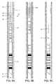
- FIGS. 1A and 1Billustrate a fracturing system, according to one embodiment of the present invention.
- FIG. 2illustrates a consumable frac plug of the system.
- FIG. 3Aillustrates an igniter of the frac plug.
- FIGS. 3B and 3Cillustrate a trigger of the igniter.
- FIGS. 4A and 4Billustrate a manufacturing system for a mandrel of the frac plug.
- FIGS. 5A-5Fillustrate a fracturing operation conducted using the system.
- FIG. 6Aillustrates an alternative consumable frac plug, according to another embodiment of the present invention.
- FIG. 6Billustrates an igniter of the alternative frac plug.
- FIG. 7Aillustrates an electronic trigger for use with either igniter, according to another embodiment of the present invention.
- FIG. 7Billustrates an alternative switch for the electronic trigger, according to another embodiment of the present invention.
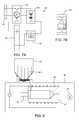
- FIG. 8illustrates an alternative manufacturing system for an alternative consumable mandrel, according to another embodiment of the present invention.
- FIGS. 1A and 1Billustrate a fracturing system 1 , according to one embodiment of the present invention.
- the fracturing system 1may include a lubricator 1 b , a fluid system 1 f , a production tree 1 p , a work line, such as wireline 1 w , and a bottomhole assembly (BHA) 1 h.
- BHAbottomhole assembly
- the work linemay be slick line or sand line.
- a work stringsuch as coiled tubing, may be used instead of the work line.
- a wellhead 2may be mounted on an outer casing string 3 o which has been deployed into a wellbore 4 drilled from a surface 5 s of the earth and cemented 6 o into the wellbore.
- An inner casing string 3 ihas been deployed into the wellbore 4 , hung from the wellhead 2 , and cemented 6 i into place.
- the outer casing string 3 omay extend to a depth adjacent a bottom of an upper formation 5 u and the inner casing string 3 i may extend through a lower formation 5 b .
- the upper formation 5 umay be non-productive and the lower formation 5 b may be a hydrocarbon-bearing reservoir having one or more production zones 7 (only one shown).
- the wellbore 4may include a vertical portion and a deviated, such as horizontal, portion.
- the production tree 1 pmay be installed on the wellhead 2 .
- the production tree 1 pmay include a master valve 8 m , a flow cross 9 , and a swab valve 8 s .
- Each component of the production tree 1 pmay be connected together, the production tree may be connected to the wellhead 2 and an injector head 10 , and the lubricator 1 b may be connected to the injector head, such as by flanges and studs or bolts and nuts.
- the fluid system 1 fmay include the injector head 10 , shutoff valve 11 , one or more gauges, such as the pressure gauges 12 p,t and a stroke counter 13 , a launcher 14 , a fracture pump 15 , and a fracture fluid mixer, such as a recirculating mixer 16 .
- the pressure gauge 12 tmay be connected to the flow cross 9 and may be operable to monitor wellhead pressure.
- the pressure gauge 12 pmay be connected between the fracture pump 15 and the valve 11 and may be operable to measure discharge pressure of the fracture pump 15 .
- the stroke counter 13may be operable to measure a flow rate of the fracture pump 15 .
- the gaugesmay be sensors in data communication with a programmable logic controller (PLC) (not shown) for automated or semi-automated control of the fracturing operation.
- PLCprogrammable logic controller
- the launcher 14may include a housing, a plunger, and an actuator.
- a pump-down plugsuch as a ball 17
- the plungermay be movable relative to the housing between a capture position and a release position.
- the plungermay be moved between the positions by the actuator.
- the actuatormay be hydraulic, such as a piston and cylinder assembly. In operation, a technician may release the ball 17 by operating the launcher actuator.
- the launcher actuatormay then move the plunger to the release position (not shown).
- the carrier and ball 17may then move into a discharge conduit connecting the fracture pump 15 to the injector head 10 .
- the pumped stream of fracturing fluid 19( FIG. 5C ) may then carry the ball 17 from the launcher 14 , into the wellhead 2 via the injector head 10 and tree 1 p , and to the frac plug 18 .
- the actuatormay be electric, pneumatic, or manual, such as a handwheel.
- the lubricator 1 bmay include a tool housing 20 (aka lubricator riser), a seal head 21 , one or more blowout preventers 22 , and the shutoff valve 8 f . Components of the lubricator 1 b may be connected, such as by flanged connections.
- the shutoff valve 8 fmay also have a lower flange for connecting to an upper flange of the injector head 10 .
- the seal head 21may include a stuffing box and a grease injector.
- the stuffing boxmay include a packing, a piston, and a housing.
- a portmay be formed through the housing in communication with the piston. The port may be connected to a hydraulic power unit (not shown) of a service truck (not shown) via a hydraulic conduit (not shown). When operated by hydraulic fluid, the piston may longitudinally compress the packing, thereby radially expanding the packing inward into engagement with the wireline 1 w.
- the grease injectormay include a housing integral with the stuffing box housing and one or more seal tubes. Each seal tube may have an inner diameter slightly larger than an outer diameter of the wireline 1 w , thereby serving as a controlled gap seal.
- An inlet port and an outlet portmay be formed through the grease injector/stuffing box housing.
- a grease conduit(not shown) may connect an outlet of a grease pump (of the service truck) with the inlet port and another grease conduit (not shown) may connect the outlet port with a grease reservoir.
- Grease(not shown) may be injected from the grease pump into the inlet port and along the slight clearance formed between the seal tube and the wireline 1 w to lubricate the wireline 1 w , reduce pressure load on the stuffing box packing, and increase service life of the stuffing box packing.
- the BHA 1 hmay include a cablehead 23 , a casing collar locator (CCL) 24 , a perforation gun 25 , a setting tool 26 , and the consumable frac plug 18 .
- the cablehead 23 , CCL 24 , and perforation gun 25may be connected together, such as by threaded connections or flanges and studs or bolts and nuts.
- the perforation gun 25may include a firing head and a charge carrier.
- the charge carriermay include a housing, a plurality (ten shown) of shaped charges, and detonation cord connecting the charges to the firing head.
- the firing headmay receive electricity from the wireline 1 w to operate an electric match thereof. The electric match may ignite the detonation cord to fire the shape charges.
- the setting tool 26may include a mandrel 26 m ( FIG. 2 ) and a piston 26 s longitudinally movable relative to the mandrel.
- the mandrel 26 mmay be connected to the perforation gun and fastened to a mandrel 27 of the frac plug 18 , such as by shearable pins 35 , screws, or ring.
- the setting tool 26may include a firing head and a power charge. In operation, the firing head may receive electricity from the wireline 1 w to operate an electric match thereof and fire the power charge. Combustion of the power charge may create high pressure gas which exerts a force on the setting piston 26 s.
- a hydraulic pumpmay be used instead of the power charge to drive the setting piston.
- coiled tubingis used instead of the wireline, high pressure fluid may be injected through the coiled tubing to drive the setting piston.
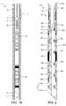
- FIG. 2illustrates the consumable frac plug 18 .
- the frac plug 18may include a consumable mandrel 27 , one or more anchors, such as upper 28 u and lower 28 b slips and respective upper 29 u and lower 29 b slip cones, an expandable sealing member, such as packing element 30 , and an igniter 31 .
- the frac plug 18may further include one or more packing supports, such as upper 32 u and lower 32 b expansion rings and respective upper 33 u and lower 33 b support cones.
- the frac plug 18may be made from one or more drillable materials.
- the cones 29 u,b and 33 u,bmay be made from a composite material.
- the composite materialmay include a polymer matrix reinforced by continuous fibers such as glass, carbon, or aramid (including para-aramids and meta-aramids).
- the polymer matrixmay be epoxy, polyurethane or phenolic.
- the slips 28 u,bmay be made from a non-steel metal or alloy, such as cast iron.
- the packing element 30may be made from a polymer, such as an elastomer or elastomer copolymer.
- the expansion rings 32 u,bmay be made from an engineering polymer, such as polytetrafluoroethylene (PTFE) or polyetheretherketone (PEEK).
- PTFEpolytetrafluoroethylene
- PEEKpolyetheretherketone
- the plug components 28 - 34may be disposed along an outer surface of the mandrel 27 .
- the packing element 30 and packing supports 32 u,b , 33 u,bmay be disposed between the slip cones 29 u,b and the upper 32 u , 33 u and lower 32 b , 33 b packing supports may straddle the packing element.
- a seal, such as an o-ring 34 u,bmay be disposed between each support cone 33 u,b and the mandrel 27 to seal the interface formed therebetween.
- the expansion rings 32 u,bmay be disposed along the mandrel 27 between the support cones 33 u,b , and the slip cones 29 u,b.
- the expansion rings 32 u,bmay each be an annular member having a base portion of a first diameter that steps up to a wedge portion of a second diameter. An inner surface of the wedge portion may taper outwardly from a longitudinal axis of the frac plug 18 .
- the expansion rings 32 u,bmay further have a shoulder may be formed between the two portions.
- Each support cone 33 u,bmay have a cone portion and a support portion.
- the cone portion of each support cone 33 u,bmay be complimentary tapered to the wedged portions of the respective expansion rigs 32 u,b .
- Equally spaced longitudinal cutsmay be fabricated in the wedge portion to create one or more wedges therebetween. The number of cuts may be determined by the size of the annulus to be sealed and the forces exerted on each expansion support ring 32 u,b.
- the angled wedgesmay pivot radially outward as each expansion ring 32 u,b moves along the outer surface of each respective support cone 33 u,b .
- the wedgesmay then sever from the base portion, and may extend radially to contact an inner surface of the inner casing 3 i ( FIG. 5A ).
- the extended wedgesmay serve as a brake that prevents slippage of the frac plug 18 relative to the inner casing 3 i .
- the support portion of each support cone 33 u,bmay abut the packing element 30 .
- a reaction force exerted on each support cone by extension of the wedgesmay serve to anchor the support cone in place along the mandrel 27 to prevent longitudinal slippage of the expanded packing element 30 .
- the mandrel 27may be a tubular member having a longitudinal bore formed therethrough.
- the mandrel 27may have a body portion 27 y , guide profile, such as a mule shoe 27 m , formed at a lower end thereof, a shoulder 27 s formed in an outer surface thereof for receiving the plug components 28 - 34 , and a seat 27 b formed in an inner surface thereof for receiving the ball 17 .
- the slips 28 u,bmay each be disposed along the mandrel 27 adjacent the respective slip cone 29 u,b .
- Each slip 28 u,bmay include an inner base portion having a tapered inner surface conforming to the respective slip cone 29 u,b and an outer wedge portion split into a plurality of wedges.
- An outer surface of each wedgemay have at least one outwardly extending serration to engage an inner surface of a the inner casing 3 i when the slips 28 u,b are driven radially outward from the mandrel 27 due to movement across the respective slip cones 29 u,b .
- the slip base portionsmay each be designed to fracture with radial stress.
- Each slip base portionmay include at least one recessed groove (not shown) milled therein to fracture under stress allowing the wedges to expand outward to engage the inner casing 3 i.
- Each slip cone 29 u,bmay be fastened to the mandrel 27 , such as by one or more respective shearable pins 36 u,b , screws, or ring.
- Each of the slip cones 29 u,bmay have an undercut formed in an end thereof for receiving the base portion of the respective expansion ring 32 u,b .
- a setting ring 37may be disposed along the mandrel 27 adjacent the upper slip 28 u for receiving the setting piston 26 s .
- the setting ring 37may be captured on the mandrel 27 by a stop 38 .
- the stop 38may be an annular member and fastened to the mandrel 27 , such as by one or more pins 39 a,b , screws, or snap ring.
- each support conemay be two separate tapered members and one member made from the engineering polymer such that it may extrude to fill voids between the wedges.
- the frac plugmay further include a ball cage and the ball trapped in the ball cage.
- the frac plugmay further include a bore plug disposed in the mandrel bore or a solid mandrel, thereby converting the frac plug to a bridge plug.
- FIG. 3Aillustrates the igniter 31 .
- FIGS. 3B and 3Cillustrate a trigger 47 of the igniter 31 .
- the igniter 31may include an upper portion of the mandrel body 27 y , an inner housing 41 , a pyrogen charge 45 , one or more (two shown) pyrotechnic composition charges (PCCs) 46 c , and the trigger 47 .
- the trigger 47may include a outer housing 40 , one or more strikers 44 , and one or more solute plugs 53 .
- Each striker 44may include a pressure relief device 48 , a plunger 50 , a solvent 51 , and a pressure port 54 .
- the outer housing 40 and inner housing 41may each be made from the non-steel metal or alloy.
- the inner housing 41may be connected to the mandrel 27 , such as by bonding with an adhesive.
- the inner housing 41may have upper and lower shoulders formed at ends thereof to engage the outer housing 40 , thereby defining an annular chamber between the inner and outer housings.
- the inner housing 41may also have one or more charge ports formed through a wall thereof for receiving the respective PCCs 46 c .
- the mandrel body 27 ymay also have one or more sockets formed in an outer surface thereof for receiving the respective PCCs 46 c .
- Each inner housing shouldermay also have a groove formed therein for receiving a seal, such as an o-ring 42 u,b .
- the outer housing 40may be fastened to the inner housing 41 , such as by a snap ring 43 or screws or bonded thereto.
- the pyrogen charge 45may be a powder or ribbons made from a water-reactive agent, such as magnesium, and having an ignition temperature sufficient to ignite the PCCs 46 c .
- the PCCs 46 cmay each be made from a pyrotechnic composition 46 m ( FIG. 4A ).
- the pyrotechnic composition 46 mmay include a fuel and an oxidant and may be thermite or thermate.
- Each PCC 46 cmay be a pellet of the pyrotechnic composition 46 m.
- the pyrogen chargemay further include an oxidant or be a mixture of the pyrotechnic composition and water-reactive agent.
- the pyrogen agentmay react with other components of wellbore fluid or chemicals injected into the well.
- the PCC 46 cmay be a tube made of the mandrel material (discussed below) and packed with the water-reactive agent and/or pyrotechnic composition. The alternative tube may also have diffusion holes formed through a wall thereof.
- the pressure relief device 48may include a rupture disk 48 d and a pair of flanges 48 i,o .
- the pressure port 54may be formed through a wall of the outer housing 40 .
- the pressure port 54may have a first shoulder formed therein for receiving the flanges 48 i,o and be threaded.
- One of the flanges 48 omay be threaded for fastening the pressure relief device 48 to the outer housing 40 .
- the rupture disk 48 dmay be metallic and have one or more scores formed in an inner surface thereof for reliably failing at a predetermined rupture pressure.
- the rupture disk 48 dmay be disposed between the flanges 48 i,o and the flanges connected together, such as by one or more fasteners 48 f .
- the flanges 48 i,omay carry one or more seals 48 s for preventing leakage around the rupture disk 48 d.
- the plunger 50may be disposed in the pressure port 54 and fastened to the outer housing 40 , such as by a shearable ring 49 r .
- the shearable ring 49 rmay be received by a second shoulder of the pressure port 54 .
- the plunger 50may have a cylindrical portion and a conical portion.
- the cylindrical portionmay have a first groove for receiving the shearable ring 49 r and a second groove for receiving a seal, such as an o-ring 49 s .
- the solvent 51may be contained in a frangible container, such as a glass vial.
- the glass vialmay be fastened to the outer housing 40 , such as by entrapment between a third shoulder of the pressure port 54 and a stop, such as snap ring 52 .
- the outer housing 40may further have one or more ignition ports formed through as wall thereof.
- a solute plug 53may be disposed in each ignition port and fastened to the housing, such as by a threaded connection.
- the rupture pressuremay correspond to a fracture pressure of the production zone 7 .
- the disk 48 dmay be operable to rupture at commencement of the fracturing operation thereby opening the pressure port 54 .
- the fracture pressuremay exert a fluid force on the plunger 50 , thereby fracturing the shearable ring 49 r and propelling the plunger into the glass vial containing the solvent 51 .
- the solvent 51may be expelled into the annular chamber in communication with the solute plugs 53 .
- the solvent 51 and solutemay be a soluble pair, such as an acid and metal.
- the solvent 51may gradually dissolve the solute plugs 53 until the pressure capability thereof is compromised, thereby leaking fracturing fluid 19 through the ignition ports and into the annular chamber.
- the solute plugs 53may be configured to withstand attack by the solvent 51 for a predetermined time period sufficient to complete the fracturing of the production zone 7 .
- the pyrogen charge 45may react with water in the fracturing fluid 19 , thereby combusting and heating the PCCs 46 c to ignition temperature.
- the PCCs 46 cmay in turn ignite the mandrel 27 .
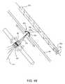
- FIGS. 4A and 4Billustrate a manufacturing system for the mandrel 27 .
- the manufacturing systemmay include two or more liquid tanks, a metering pump 55 p for each liquid tank, a metering hopper 55 h , and a mixing trough 55 t .
- An inlet of each metering pump 55 pmay be connected to the respective liquid tank.
- a first of the liquid tanksmay include a first polymer reagent, such as epoxide 54 m
- a second of the tanksmay include a second polymer reagent, such as polyamine 54 h .
- the metering hopper 55 hmay include the pyrotechnic composition 46 m in powder or nanoparticle form.
- the metering pumps 55 p and metering hopper 55 mmay be operated to dispense proportionate quantities of the reagents 54 m,h and the PCC 46 into the mixing trough 55 t .
- the mixing trough 55 tmay then mix the quantities into a resin 56 .
- the resin 56may include an uncured polymer, such as epoxy, infused with the pyrotechnic composition particulates.
- the first reagentmay be isocyanate and the second reagent may be polyol.
- the first reagentmay be phenol and the second reagent may be formaldehyde.
- the manufacturing systemmay include a third liquid tank containing a diluent and a third metering pump for dispensing the diluent into the mixing trough or one or both of the reagents may be pre-diluted.
- a blank 27 k of the mandrel 27may be formed by filament winding.
- Continuous fibers 57 fsuch as glass, carbon, or aramid (including para-aramids and meta-aramids) fibers, may be fed through the mixed resin 56 via one or more sheaves of the mixing trough 55 t , thereby coating the fibers with the resin.
- the coated fibers 57 cmay continue into a fiber placement hood 58 h .
- the fiber placement hood 58 hmay consolidate the multiple coated fibers 57 c into a fiber bundle 57 g and feed the fiber bundle to a winding mandrel 59 w , thereby forming the plug mandrel blank 27 k.
- the fiber placement hood 58 h and the winding mandrel 59 wmay be positioned parallel to one another.
- the fiber placement hood 58 hmay include a carriage 58 c and a track 58 t .
- the carriage 58 cmay be reciprocated along a longitudinal axis of the track 58 t , such as by a linear actuator (not shown).
- the winding mandrel 59 wmay be rotated about a winding axis 59 x , such as by an electric motor (not shown).
- the fiber placement hood 58 hmay dispense the fiber bundle 57 g to the winding mandrel at a winding angle 58 a relative to the winding axis 59 x .
- the winding angle 58 amay range from thirty to seventy degrees.
- the winding angle 58 a of the fiber placement hood 58 hmay be altered by adjusting the speed that the carriage 58 c translates along the track 58 t relative to the angular speed of the winding mandrel 59 w .
- Each pass of the carriage 58 c along the track 58 tmay form a respective layer of the mandrel blank 27 k and the carriage may be reciprocated until a desired outer diameter of the blank 27 k is formed.
- the mandrel blank and winding mandrel 59 wmay be placed in an oven (not shown) and heated and/or irradiated to cure the resin 56 . After curing, the mandrel blank 27 k may be removed from the winding mandrel 59 w and machined to form the plug mandrel 27 .
- the fibers 57 fmay be pre-impregnated with the resin 56 and dry wound or post-impregnated with the resin.
- the mandrel blank 27 kmay be formed by pultrusion.
- the mandrel blank 27may be compression molded, injection molded, or reaction injection molded using mats impregnated with the resin 56 or a mixture of the resin 56 and chopped fiber.
- other plug componentssuch as the cones 29 u,b , 33 u,b and/or fasteners 35 , 36 u,b , 39 a,b , may be made using the resin 56 or coated fibers 57 c .
- a tubular for a downhole toolmay be made instead of the mandrel blank 27 k.
- FIGS. 5A-5Fillustrate a fracturing operation conducted using the system 1 .
- the BHA 1 hmay be deployed into the wellbore 4 using the wireline 1 w with assistance from the fracture pump 15 .
- the fracture pump 15may be operated to pump displacement fluid (not shown) just before the BHA 1 h has been inserted into the wellbore 4 .
- Pumping of the displacement fluidmay increase pressure in the inner casing bore until a differential is sufficient to open a toe sleeve (not shown) of the inner casing string 3 i .
- the BHA 1 hmay be inserted into the wellbore 4 and continued pumping of the displacement fluid may drive the BHA 1 h to a setting depth below the production zone 7 .
- the displaced fluidmay be forced into the lower formation 5 b via the open toe sleeve.
- the frac plug 18may be set by supplying electricity to the BHA at a first polarity via the wireline 1 w to activate the setting tool 26 .
- the setting piston 26 smay be driven toward the mule shoe 27 m while the wireline 1 w restrains the setting mandrel 26 m and plug mandrel 27 , thereby compressing the packing element 30 and driving the slips 28 u,b along the respective slip cones 29 u,b .
- the packing element 30may be radially expanded into engagement with the inner casing string 3 i and the slips 28 u,b may be radially extended into engagement with the inner casing.
- a tensile forcemay then be exerted on the BHA 1 h by pulling the wireline 1 w from the surface 5 s to fracture the shearable pins 35 , thereby releasing the frac plug 18 from the rest of the BHA 23 - 26 .
- the remaining BHA 23 - 26may then be raised using the wireline 1 w until the perforation guns 25 are aligned with the production zone 7 .
- Electricitymay then be resupplied to the remaining BHA 23 - 26 via the wireline 1 w at a second polarity to fire the perforation guns 25 into the inner casing 3 i , thereby forming perforations 60 p .
- the remaining BHA 23 - 26may be retrieved to the lubricator 1 b and into the tool housing 20 using the wireline 1 w .
- the lubricator shutoff valve 8 fmay then be closed.
- the ball 17may then be released from the launcher 14 and the fracturing fluid 19 may be pumped from the mixer 16 into the injector head 10 via the valve 11 by the fracture pump 15 .
- the fracturing fluid 19may be a slurry including: proppant (i.e., sand), water, and chemical additives.
- proppanti.e., sand
- wateri.e., water
- chemical additivesi.e., water
- Continued pumping of the fracturing fluid 19may drive the ball 17 toward the frac plug 18 until the ball lands onto the plug mandrel seat 27 b , thereby closing the plug mandrel bore.
- Continued pumping of the fracturing fluid 19may exert pressure on the seated ball 17 until pressure in the inner casing string 3 i increases to force the fracturing fluid (above the seated ball) through the perforations 60 p , cement 6 i and into the production zone 7 by creating a fracture 60 f .
- the increased pressuremay also fracture the rupture disk 48 d and drive the plunger 50 into the solvent vial of the trigger 47 .
- the proppantmay be deposited into the fracture 60 f by the fracturing fluid 19 .
- Pumping of the fracturing fluid 19may continue until a desired quantity has been pumped into the production zone 7 .
- the igniter 31may initiate incineration 61 of the plug mandrel 27 .
- the plug mandrel 27has been incinerated 61 leaving only plug debris 18 d , one or more additional production zones (not shown) may be fractured using one or more additional respective BHAs (not shown) in a similar fashion.
- the lubricator 1 b and injector head 10may be removed from the tree 1 p .
- the flow cross 9may be connected to a disposal pit or tank (not shown) and fracturing fluid 19 allowed to flow from the wellbore 4 to the pit.
- a work string, such as coiled tubing 1 c , and an additional BHA 62 j,smay be deployed into the wellbore 4 using a coiled tubing unit (CTU) (not shown).
- the CTUmay include an injector, a reel of the coiled tubing 1 c , a tool housing, a stuffing box, one or more BOPs and a shutoff valve.
- the BHA 62 j,smay include a jetting tool 62 j and a guide shoe 62 s .
- the injectormay be operated to lower the coiled tubing 62 c and BHA 62 j,s into the wellbore 4 and the fracture pump 15 operated to inject washing fluid through the BHA 62 j,s to the jetting tool 62 j .
- the jetting tool 62 jmay spray the washing fluid against the inner casing string 3 i to dislodge the plug debris 18 d and the returning washing fluid may carry the plug debris to the surface for disposal.
- the BHA 62 j,s and coiled tubing 62 cmay then be retrieved to the surface 5 s and the CTU removed from the tree 1 p .
- a production choke(not shown) may be connected to the flow cross 9 and to a separation, treatment, and storage facility (not shown). Production of the fractured zones 7 may then commence.
- the CT BHAmay include a drilling motor, such as a mud motor, and one or more mill bits.
- the milling BHAmay then be operated by pumping milling fluid through the coiled tubing to mill the plug debris and the milling fluid may return the milled debris to the surface.
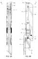
- FIG. 6Aillustrates an alternative consumable frac plug 68 , according to another embodiment of the present invention.
- FIG. 6Billustrates an igniter 71 of the alternative frac plug 68 .
- the frac plug 68may include a consumable mandrel 77 , the slips and the slip cones, the packing, and an igniter 71 .
- the igniter 71may include an upper portion of the mandrel body 77 y , a ball seat 75 , a inner housing 72 , the pyrogen charge 45 , the PCC 46 c , and a trigger.
- the triggermay include an outer housing 70 , one or more strikers, and a solute strip 73 .
- Each strikermay include the pressure relief device 48 , a plunger 50 , the solvent 51 , and a pressure port 74 .
- the alternative frac plug 68may operate in a similar fashion to the frac plug 18 .
- the pressure port 74may be a longitudinal passage formed through the housing 70 .
- the pressure portmay be a radial passage having the pressure relief device and plunger disposed therein and the longitudinal passage may be used for containing the solvent vial.
- FIG. 7Aillustrates an electronic trigger 80 for use with either igniter 31 , 71 , according to another embodiment of the present invention.
- the electronic trigger 80may include a timer battery 81 , a pressure switch 82 , an electronic timer switch 83 , an ignition battery 84 , and an ignition valve 85 .
- the trigger 80may function in a similar fashion to the trigger 47 .
- the pressure switch 82may close in response to fracture pressure. Closing of the pressure switch 82 may supply electricity to the electronic timer switch 83 from the timer battery 81 .
- the electronic timer switch 83may commence countdown in response to being powered and close at the end of countdown, thereby supplying electricity to the ignition valve 85 from the ignition battery 84 .
- the ignition valve 85may be an actuated shutoff valve disposed in each ignition port of the outer housing 40 instead of the respective solute plug 53 or in place of the solute disk 73 .
- the ignition valve 85may fail to the closed position and open in response to being powered by the ignition battery 84 .
- capacitors or inductorsmay be used instead of one or both of the batteries 81 , 84 .
- the triggermay include an electric match instead of the valve and the pyrogen may be a pyrotechnic composition.
- FIG. 7Billustrates an alternative switch 86 for the electronic trigger 80 , according to another embodiment of the present invention.
- the alternative switch 86may replace the pressure switch 86 and close in response to seating of the ball 17 in the ball seat 27 b , 75 .
- the switchmay close in response to disconnection of the setting tool from the frac plug.
- FIG. 8illustrates an alternative manufacturing system for an alternative consumable mandrel (not shown), according to another embodiment of the present invention.
- the manufacturing systemmay include the metering hopper 55 h , an extrusion die 91 , a press 92 , a heater 93 , and a spool 94 .
- the metering hopper 55 hmay dispense the pyrotechnic composition 46 m into the die 91 .
- a dispensing port of the diemay then be closed and a protective atmosphere 95 established around the die 91 and the spool 94 .
- the heater 93may be operated to heat the die 91 and pyrotechnic composition 46 m .
- the press 92may then be operated to extrude the heated pyrotechnic composition 46 m through an extrusion port of the die 91 , thereby sintering the pyrotechnic composition particulates into a fiber.
- the spool 94may then be rotated to wind the sintered fiber.
- the sintered pyrotechnic composition fibermay then be used instead of one of the fibers 57 f of the filament winding system of FIG. 4B with a non-infused resin.
- the pyrotechnic compositionmay be cold pressed into a billet and the billet loaded into the die 91 and then hot extruded into a sintered fiber.
- the sintered fibermay be used in conjunction with the infused resin 56 to manufacture the plug mandrel.
Landscapes
- Engineering & Computer Science (AREA)
- Geology (AREA)
- Life Sciences & Earth Sciences (AREA)
- Mining & Mineral Resources (AREA)
- Geochemistry & Mineralogy (AREA)
- Fluid Mechanics (AREA)
- Environmental & Geological Engineering (AREA)
- General Life Sciences & Earth Sciences (AREA)
- Physics & Mathematics (AREA)
- Mechanical Engineering (AREA)
- Chemical Kinetics & Catalysis (AREA)
- Chemical & Material Sciences (AREA)
- General Chemical & Material Sciences (AREA)
- Filling Or Discharging Of Gas Storage Vessels (AREA)
- Pressure Vessels And Lids Thereof (AREA)
- Air Bags (AREA)
- Structural Engineering (AREA)
- Textile Engineering (AREA)
Abstract
Description
Claims (20)
Priority Applications (3)
| Application Number | Priority Date | Filing Date | Title |
|---|---|---|---|
| US14/164,809US9482069B2 (en) | 2013-03-07 | 2014-01-27 | Consumable downhole packer or plug |
| PCT/US2014/021332WO2014138444A2 (en) | 2013-03-07 | 2014-03-06 | Consumable downhole packer or plug |
| US15/276,492US10415343B2 (en) | 2013-03-07 | 2016-09-26 | Consumable downhole packer or plug |
Applications Claiming Priority (2)
| Application Number | Priority Date | Filing Date | Title |
|---|---|---|---|
| US201361774137P | 2013-03-07 | 2013-03-07 | |
| US14/164,809US9482069B2 (en) | 2013-03-07 | 2014-01-27 | Consumable downhole packer or plug |
Related Child Applications (1)
| Application Number | Title | Priority Date | Filing Date |
|---|---|---|---|
| US15/276,492DivisionUS10415343B2 (en) | 2013-03-07 | 2016-09-26 | Consumable downhole packer or plug |
Publications (2)
| Publication Number | Publication Date |
|---|---|
| US20140251612A1 US20140251612A1 (en) | 2014-09-11 |
| US9482069B2true US9482069B2 (en) | 2016-11-01 |
Family
ID=51486406
Family Applications (2)
| Application Number | Title | Priority Date | Filing Date |
|---|---|---|---|
| US14/164,809Expired - Fee RelatedUS9482069B2 (en) | 2013-03-07 | 2014-01-27 | Consumable downhole packer or plug |
| US15/276,492Expired - Fee RelatedUS10415343B2 (en) | 2013-03-07 | 2016-09-26 | Consumable downhole packer or plug |
Family Applications After (1)
| Application Number | Title | Priority Date | Filing Date |
|---|---|---|---|
| US15/276,492Expired - Fee RelatedUS10415343B2 (en) | 2013-03-07 | 2016-09-26 | Consumable downhole packer or plug |
Country Status (2)
| Country | Link |
|---|---|
| US (2) | US9482069B2 (en) |
| WO (1) | WO2014138444A2 (en) |
Cited By (19)
| Publication number | Priority date | Publication date | Assignee | Title |
|---|---|---|---|---|
| US20160208575A1 (en)* | 2015-01-21 | 2016-07-21 | Trican Completion Solutions Ltd | Burst port sub with dissolvable barrier |
| US20160237781A1 (en)* | 2015-02-13 | 2016-08-18 | Weatherford Technology Holdings, Llc | Time Delay Toe Sleeve |
| US10415343B2 (en) | 2013-03-07 | 2019-09-17 | Weatherford Technology Holdings, Llc | Consumable downhole packer or plug |
| US10443331B1 (en) | 2018-12-27 | 2019-10-15 | Diamondback Industries, Inc. | Self-set full bore frac plug |
| US10927627B2 (en) | 2019-05-14 | 2021-02-23 | DynaEnergetics Europe GmbH | Single use setting tool for actuating a tool in a wellbore |
| US11204224B2 (en) | 2019-05-29 | 2021-12-21 | DynaEnergetics Europe GmbH | Reverse burn power charge for a wellbore tool |
| US11255147B2 (en) | 2019-05-14 | 2022-02-22 | DynaEnergetics Europe GmbH | Single use setting tool for actuating a tool in a wellbore |
| US11299957B2 (en) | 2018-08-30 | 2022-04-12 | Avalon Research Ltd. | Plug for a coiled tubing string |
| US11408279B2 (en) | 2018-08-21 | 2022-08-09 | DynaEnergetics Europe GmbH | System and method for navigating a wellbore and determining location in a wellbore |
| US11578549B2 (en) | 2019-05-14 | 2023-02-14 | DynaEnergetics Europe GmbH | Single use setting tool for actuating a tool in a wellbore |
| US11753889B1 (en) | 2022-07-13 | 2023-09-12 | DynaEnergetics Europe GmbH | Gas driven wireline release tool |
| US11761281B2 (en) | 2019-10-01 | 2023-09-19 | DynaEnergetics Europe GmbH | Shaped power charge with integrated initiator |
| US11808145B2 (en) | 2021-10-29 | 2023-11-07 | Halliburton Energy Services, Inc. | Downhole telemetry during fluid injection operations |
| US11808093B2 (en) | 2018-07-17 | 2023-11-07 | DynaEnergetics Europe GmbH | Oriented perforating system |
| US11946728B2 (en) | 2019-12-10 | 2024-04-02 | DynaEnergetics Europe GmbH | Initiator head with circuit board |
| USRE50204E1 (en) | 2013-08-26 | 2024-11-12 | DynaEnergetics Europe GmbH | Perforating gun and detonator assembly |
| US12139984B2 (en) | 2022-04-15 | 2024-11-12 | Dbk Industries, Llc | Fixed-volume setting tool |
| US12241326B2 (en) | 2019-05-14 | 2025-03-04 | DynaEnergetics Europe GmbH | Single use setting tool for actuating a tool in a wellbore |
| US12378833B2 (en) | 2022-07-13 | 2025-08-05 | DynaEnergetics Europe GmbH | Gas driven wireline release tool |
Families Citing this family (63)
| Publication number | Priority date | Publication date | Assignee | Title |
|---|---|---|---|---|
| US20090107684A1 (en) | 2007-10-31 | 2009-04-30 | Cooke Jr Claude E | Applications of degradable polymers for delayed mechanical changes in wells |
| US20040231845A1 (en) | 2003-05-15 | 2004-11-25 | Cooke Claude E. | Applications of degradable polymers in wells |
| US9587475B2 (en) | 2008-12-23 | 2017-03-07 | Frazier Ball Invention, LLC | Downhole tools having non-toxic degradable elements and their methods of use |
| US9217319B2 (en) | 2012-05-18 | 2015-12-22 | Frazier Technologies, L.L.C. | High-molecular-weight polyglycolides for hydrocarbon recovery |
| US9500061B2 (en) | 2008-12-23 | 2016-11-22 | Frazier Technologies, L.L.C. | Downhole tools having non-toxic degradable elements and methods of using the same |
| US9506309B2 (en) | 2008-12-23 | 2016-11-29 | Frazier Ball Invention, LLC | Downhole tools having non-toxic degradable elements |
| CA2755848C (en)* | 2011-10-19 | 2016-08-16 | Ten K Energy Service Ltd. | Insert assembly for downhole perforating apparatus |
| US10337279B2 (en) | 2014-04-02 | 2019-07-02 | Magnum Oil Tools International, Ltd. | Dissolvable downhole tools comprising both degradable polymer acid and degradable metal alloy elements |
| US9157288B2 (en) | 2012-07-19 | 2015-10-13 | General Plastics & Composites, L.P. | Downhole tool system and method related thereto |
| US9702680B2 (en) | 2013-07-18 | 2017-07-11 | Dynaenergetics Gmbh & Co. Kg | Perforation gun components and system |
| US9759040B2 (en) | 2013-12-20 | 2017-09-12 | Weatherford Technology Holdings, Llc | Autonomous selective shifting tool |
| US20150211328A1 (en)* | 2014-01-30 | 2015-07-30 | Olympic Research, Inc. | Well sealing via thermite reactions |
| US9394757B2 (en) | 2014-01-30 | 2016-07-19 | Olympic Research, Inc. | Well sealing via thermite reactions |
| US9228412B2 (en)* | 2014-01-30 | 2016-01-05 | Olympic Research, Inc. | Well sealing via thermite reactions |
| CA2935508C (en) | 2014-04-02 | 2020-06-09 | W. Lynn Frazier | Downhole plug having dissolvable metallic and dissolvable acid polymer elements |
| US10242312B2 (en) | 2014-06-06 | 2019-03-26 | Quantico Energy Solutions, Llc. | Synthetic logging for reservoir stimulation |
| US9745847B2 (en)* | 2014-08-27 | 2017-08-29 | Baker Hughes Incorporated | Conditional occlusion release device |
| WO2016069305A1 (en)* | 2014-10-31 | 2016-05-06 | Schlumberger Canada Limited | Non-explosive downhole perforating and cutting tools |
| US20160348464A1 (en)* | 2015-05-27 | 2016-12-01 | Wild Well Control, Inc. | Method of sealing wells by injection of sealant |
| CA2985098C (en)* | 2015-06-23 | 2020-10-06 | Weatherford Technology Holdings, Llc | Self-removing plug for pressure isolation in tubing of well |
| US20170044859A1 (en)* | 2015-08-10 | 2017-02-16 | Tyler W. Blair | Slip Element and Assembly for Oilfield Tubular Plug |
| US10214988B2 (en) | 2015-08-12 | 2019-02-26 | Csi Technologies Llc | Riserless abandonment operation using sealant and cement |
| US10670186B1 (en)* | 2015-11-18 | 2020-06-02 | Cornerstone Research Group, Inc. | Fiber reinforced energetic composite |
| NO20151689A1 (en)* | 2015-12-09 | 2017-06-12 | Interwell P&A As | Ignitor, system and method of electrical ignition of exothermic mixture |
| US11506013B2 (en)* | 2016-01-08 | 2022-11-22 | Sc Asset Corporation | Collet baffle system and method for fracking a hydrocarbon formation |
| GB201600468D0 (en)* | 2016-01-11 | 2016-02-24 | Paradigm Flow Services Ltd | Fluid discharge apparatus and method of use |
| WO2017123217A1 (en)* | 2016-01-13 | 2017-07-20 | Halliburton Energy Services, Inc. | High-pressure jetting and data communication during subterranean perforation operations |
| US10077626B2 (en)* | 2016-05-06 | 2018-09-18 | Baker Hughes, A Ge Company, Llc | Fracturing plug and method of fracturing a formation |
| US10807189B2 (en) | 2016-09-26 | 2020-10-20 | Schlumberger Technology Corporation | System and methodology for welding |
| US10364632B2 (en) | 2016-12-20 | 2019-07-30 | Baker Hughes, A Ge Company, Llc | Downhole assembly including degradable-on-demand material and method to degrade downhole tool |
| US10450840B2 (en) | 2016-12-20 | 2019-10-22 | Baker Hughes, A Ge Company, Llc | Multifunctional downhole tools |
| US10865617B2 (en) | 2016-12-20 | 2020-12-15 | Baker Hughes, A Ge Company, Llc | One-way energy retention device, method and system |
| US10364630B2 (en) | 2016-12-20 | 2019-07-30 | Baker Hughes, A Ge Company, Llc | Downhole assembly including degradable-on-demand material and method to degrade downhole tool |
| US10364631B2 (en)* | 2016-12-20 | 2019-07-30 | Baker Hughes, A Ge Company, Llc | Downhole assembly including degradable-on-demand material and method to degrade downhole tool |
| US10487615B2 (en)* | 2017-03-22 | 2019-11-26 | Nine Downhole Technologies, Llc | Cup plug having a large flow-through inside diameter |
| US10221641B2 (en) | 2017-03-29 | 2019-03-05 | Baker Hughes, A Ge Company, Llc | Downhole tools having controlled degradation and method |
| US10221642B2 (en) | 2017-03-29 | 2019-03-05 | Baker Hughes, A Ge Company, Llc | Downhole tools having controlled degradation and method |
| US10221643B2 (en) | 2017-03-29 | 2019-03-05 | Baker Hughes, A Ge Company, Llc | Downhole tools having controlled degradation and method |
| US10167691B2 (en) | 2017-03-29 | 2019-01-01 | Baker Hughes, A Ge Company, Llc | Downhole tools having controlled disintegration |
| US10227839B2 (en)* | 2017-04-07 | 2019-03-12 | Baker Hughes, A Ge Company, Llc | Pressure-triggered degradable-on-command component of a downhole tool and method |
| US10428261B2 (en) | 2017-06-08 | 2019-10-01 | Csi Technologies Llc | Resin composite with overloaded solids for well sealing applications |
| US10378299B2 (en) | 2017-06-08 | 2019-08-13 | Csi Technologies Llc | Method of producing resin composite with required thermal and mechanical properties to form a durable well seal in applications |
| US11015409B2 (en) | 2017-09-08 | 2021-05-25 | Baker Hughes, A Ge Company, Llc | System for degrading structure using mechanical impact and method |
| US10781676B2 (en) | 2017-12-14 | 2020-09-22 | Schlumberger Technology Corporation | Thermal cutter |
| US20200408055A1 (en)* | 2017-12-22 | 2020-12-31 | Ensign-Bickford Aerospace & Defense Company | Frac-ball with exothermic reaction constituents |
| US11053782B2 (en) | 2018-04-06 | 2021-07-06 | DynaEnergetics Europe GmbH | Perforating gun system and method of use |
| US10458213B1 (en) | 2018-07-17 | 2019-10-29 | Dynaenergetics Gmbh & Co. Kg | Positioning device for shaped charges in a perforating gun module |
| US10876374B2 (en) | 2018-11-16 | 2020-12-29 | Weatherford Technology Holdings, Llc | Degradable plugs |
| CN111502585B (en)* | 2019-01-30 | 2022-07-05 | 中国石油天然气股份有限公司 | Internal sealing tool for fireflooding |
| CA3147161A1 (en) | 2019-07-19 | 2021-01-28 | DynaEnergetics Europe GmbH | Ballistically actuated wellbore tool |
| CN110439522B (en)* | 2019-08-16 | 2022-03-18 | 中国石油化工集团有限公司 | Controllable dissolution opening device of the first stage fracturing channel and construction technology of fracturing staged operation |
| US12084962B2 (en) | 2020-03-16 | 2024-09-10 | DynaEnergetics Europe GmbH | Tandem seal adapter with integrated tracer material |
| CN112610182B (en)* | 2021-01-13 | 2021-10-12 | 大庆宏升石油机械设备制造有限公司 | Intelligent non-stop packing sealing device for pumping unit wellhead sucker rod |
| WO2022167297A1 (en) | 2021-02-04 | 2022-08-11 | DynaEnergetics Europe GmbH | Perforating gun assembly with performance optimized shaped charge load |
| US11499401B2 (en) | 2021-02-04 | 2022-11-15 | DynaEnergetics Europe GmbH | Perforating gun assembly with performance optimized shaped charge load |
| US11846171B2 (en)* | 2021-02-15 | 2023-12-19 | Vertice Oil Tools Inc. | Methods and systems for fracing and casing pressuring |
| US11555377B2 (en)* | 2021-02-15 | 2023-01-17 | Vertice Oil Tools Inc. | Methods and systems for fracing |
| US11713625B2 (en) | 2021-03-03 | 2023-08-01 | DynaEnergetics Europe GmbH | Bulkhead |
| WO2022184732A1 (en) | 2021-03-03 | 2022-09-09 | DynaEnergetics Europe GmbH | Bulkhead and tandem seal adapter |
| US12366142B2 (en) | 2021-03-03 | 2025-07-22 | DynaEnergetics Europe GmbH | Modular perforating gun system |
| US11732556B2 (en) | 2021-03-03 | 2023-08-22 | DynaEnergetics Europe GmbH | Orienting perforation gun assembly |
| CN113863913B (en)* | 2021-09-08 | 2022-11-25 | 西南石油大学 | Shale gas layer oxidation burst transformation method |
| US12253339B2 (en) | 2021-10-25 | 2025-03-18 | DynaEnergetics Europe GmbH | Adapter and shaped charge apparatus for optimized perforation jet |
Citations (16)
| Publication number | Priority date | Publication date | Assignee | Title |
|---|---|---|---|---|
| US6948535B2 (en) | 2004-01-15 | 2005-09-27 | Halliburton Energy Services, Inc. | Apparatus and method for accurately metering and conveying dry powder or granular materials to a blender in a substantially closed system |
| US20050281968A1 (en)* | 2004-06-16 | 2005-12-22 | Alliant Techsystems Inc. | Energetic structural material |
| US20070202001A1 (en) | 2004-04-15 | 2007-08-30 | Nv Bekaert Sa | Method Of Manufacturing Of A Sintered Metal Fiber Medium |
| US20080017379A1 (en)* | 2006-07-20 | 2008-01-24 | Halliburton Energy Services, Inc. | Method for removing a sealing plug from a well |
| US7383876B2 (en) | 2001-08-03 | 2008-06-10 | Weatherford/Lamb, Inc. | Cutting tool for use in a wellbore tubular |
| US20090011247A1 (en) | 2007-07-02 | 2009-01-08 | Oil States Industries, Inc. | Molded Composite Mandrel for a Downhole Zonal Isolation Tool |
| WO2010019252A1 (en) | 2008-08-13 | 2010-02-18 | Robertson Michael C | Consumable downhole tool |
| US7799408B2 (en) | 2001-01-24 | 2010-09-21 | Kaken Tech Co. Ltd. | Conductive powder, conductive composition, and producing method of the same |
| US7819048B2 (en) | 2005-04-08 | 2010-10-26 | Raytheon Company | Separable structure material method |
| US20110024103A1 (en) | 2009-07-28 | 2011-02-03 | Storm Jr Bruce H | Method and apparatus for providing a conductor in a tubular |
| US20110204299A1 (en) | 2008-10-31 | 2011-08-25 | Japan Ae Power Systems Corporation | Electrode material for vacuum circuit breaker and method of manufacturing the same |
| US8127856B1 (en) | 2008-08-15 | 2012-03-06 | Exelis Inc. | Well completion plugs with degradable components |
| US8268222B2 (en) | 2001-02-15 | 2012-09-18 | Integral Technologies, Inc. | Methods of making electrical motor components from conductive loaded resin-based materials |
| US8291970B2 (en) | 2006-06-08 | 2012-10-23 | Halliburton Energy Services Inc. | Consumable downhole tools |
| US20120292053A1 (en) | 2011-05-19 | 2012-11-22 | Baker Hughes Incorporated | Easy Drill Slip with Degradable Materials |
| US8322426B2 (en)* | 2010-04-28 | 2012-12-04 | Halliburton Energy Services, Inc. | Downhole actuator apparatus having a chemically activated trigger |
Family Cites Families (2)
| Publication number | Priority date | Publication date | Assignee | Title |
|---|---|---|---|---|
| KR100986468B1 (en)* | 2009-11-19 | 2010-10-08 | 엘지이노텍 주식회사 | Lense and light emitting apparatus including the lense |
| US9482069B2 (en) | 2013-03-07 | 2016-11-01 | Weatherford Technology Holdings, Llc | Consumable downhole packer or plug |
- 2014
- 2014-01-27USUS14/164,809patent/US9482069B2/ennot_activeExpired - Fee Related
- 2014-03-06WOPCT/US2014/021332patent/WO2014138444A2/enactiveApplication Filing
- 2016
- 2016-09-26USUS15/276,492patent/US10415343B2/ennot_activeExpired - Fee Related
Patent Citations (18)
| Publication number | Priority date | Publication date | Assignee | Title |
|---|---|---|---|---|
| US7799408B2 (en) | 2001-01-24 | 2010-09-21 | Kaken Tech Co. Ltd. | Conductive powder, conductive composition, and producing method of the same |
| US8268222B2 (en) | 2001-02-15 | 2012-09-18 | Integral Technologies, Inc. | Methods of making electrical motor components from conductive loaded resin-based materials |
| US7383876B2 (en) | 2001-08-03 | 2008-06-10 | Weatherford/Lamb, Inc. | Cutting tool for use in a wellbore tubular |
| US6948535B2 (en) | 2004-01-15 | 2005-09-27 | Halliburton Energy Services, Inc. | Apparatus and method for accurately metering and conveying dry powder or granular materials to a blender in a substantially closed system |
| US20070202001A1 (en) | 2004-04-15 | 2007-08-30 | Nv Bekaert Sa | Method Of Manufacturing Of A Sintered Metal Fiber Medium |
| US20050281968A1 (en)* | 2004-06-16 | 2005-12-22 | Alliant Techsystems Inc. | Energetic structural material |
| US7819048B2 (en) | 2005-04-08 | 2010-10-26 | Raytheon Company | Separable structure material method |
| US8291970B2 (en) | 2006-06-08 | 2012-10-23 | Halliburton Energy Services Inc. | Consumable downhole tools |
| US7591318B2 (en) | 2006-07-20 | 2009-09-22 | Halliburton Energy Services, Inc. | Method for removing a sealing plug from a well |
| US20080017379A1 (en)* | 2006-07-20 | 2008-01-24 | Halliburton Energy Services, Inc. | Method for removing a sealing plug from a well |
| US20090011247A1 (en) | 2007-07-02 | 2009-01-08 | Oil States Industries, Inc. | Molded Composite Mandrel for a Downhole Zonal Isolation Tool |
| US8235102B1 (en) | 2008-03-26 | 2012-08-07 | Robertson Intellectual Properties, LLC | Consumable downhole tool |
| WO2010019252A1 (en) | 2008-08-13 | 2010-02-18 | Robertson Michael C | Consumable downhole tool |
| US8127856B1 (en) | 2008-08-15 | 2012-03-06 | Exelis Inc. | Well completion plugs with degradable components |
| US20110204299A1 (en) | 2008-10-31 | 2011-08-25 | Japan Ae Power Systems Corporation | Electrode material for vacuum circuit breaker and method of manufacturing the same |
| US20110024103A1 (en) | 2009-07-28 | 2011-02-03 | Storm Jr Bruce H | Method and apparatus for providing a conductor in a tubular |
| US8322426B2 (en)* | 2010-04-28 | 2012-12-04 | Halliburton Energy Services, Inc. | Downhole actuator apparatus having a chemically activated trigger |
| US20120292053A1 (en) | 2011-05-19 | 2012-11-22 | Baker Hughes Incorporated | Easy Drill Slip with Degradable Materials |
Non-Patent Citations (3)
| Title |
|---|
| Donald R. Askeland; Excerpt from the Science and Engineering of Materials, Third Edition, PWS Publishing Company, Boston, MA, 1984, pp. 553 and 569. |
| Ebay Listing of Pencil: Rare Inert WWII U.S. Delay Time Pencil for Blasting (Mar. 6, 2011). |
| PCT International Search Report and Written Opinion dated Feb. 17, 2015, for International Application No. PCT/US2014/021332. |
Cited By (23)
| Publication number | Priority date | Publication date | Assignee | Title |
|---|---|---|---|---|
| US10415343B2 (en) | 2013-03-07 | 2019-09-17 | Weatherford Technology Holdings, Llc | Consumable downhole packer or plug |
| USRE50204E1 (en) | 2013-08-26 | 2024-11-12 | DynaEnergetics Europe GmbH | Perforating gun and detonator assembly |
| US20160208575A1 (en)* | 2015-01-21 | 2016-07-21 | Trican Completion Solutions Ltd | Burst port sub with dissolvable barrier |
| US10767443B2 (en)* | 2015-01-21 | 2020-09-08 | Trican Completion Solutions Ltd | Burst port sub with dissolvable barrier |
| US20160237781A1 (en)* | 2015-02-13 | 2016-08-18 | Weatherford Technology Holdings, Llc | Time Delay Toe Sleeve |
| US10036229B2 (en)* | 2015-02-13 | 2018-07-31 | Weatherford Technology Holdings, Llc | Time delay toe sleeve |
| US11808093B2 (en) | 2018-07-17 | 2023-11-07 | DynaEnergetics Europe GmbH | Oriented perforating system |
| US11408279B2 (en) | 2018-08-21 | 2022-08-09 | DynaEnergetics Europe GmbH | System and method for navigating a wellbore and determining location in a wellbore |
| US11299957B2 (en) | 2018-08-30 | 2022-04-12 | Avalon Research Ltd. | Plug for a coiled tubing string |
| US10443331B1 (en) | 2018-12-27 | 2019-10-15 | Diamondback Industries, Inc. | Self-set full bore frac plug |
| US10927627B2 (en) | 2019-05-14 | 2021-02-23 | DynaEnergetics Europe GmbH | Single use setting tool for actuating a tool in a wellbore |
| US11578549B2 (en) | 2019-05-14 | 2023-02-14 | DynaEnergetics Europe GmbH | Single use setting tool for actuating a tool in a wellbore |
| US11255147B2 (en) | 2019-05-14 | 2022-02-22 | DynaEnergetics Europe GmbH | Single use setting tool for actuating a tool in a wellbore |
| US12241326B2 (en) | 2019-05-14 | 2025-03-04 | DynaEnergetics Europe GmbH | Single use setting tool for actuating a tool in a wellbore |
| US11204224B2 (en) | 2019-05-29 | 2021-12-21 | DynaEnergetics Europe GmbH | Reverse burn power charge for a wellbore tool |
| US11761281B2 (en) | 2019-10-01 | 2023-09-19 | DynaEnergetics Europe GmbH | Shaped power charge with integrated initiator |
| US11946728B2 (en) | 2019-12-10 | 2024-04-02 | DynaEnergetics Europe GmbH | Initiator head with circuit board |
| US12332034B2 (en) | 2019-12-10 | 2025-06-17 | DynaEnergetics Europe GmbH | Initiator head with circuit board |
| US11808145B2 (en) | 2021-10-29 | 2023-11-07 | Halliburton Energy Services, Inc. | Downhole telemetry during fluid injection operations |
| US12139984B2 (en) | 2022-04-15 | 2024-11-12 | Dbk Industries, Llc | Fixed-volume setting tool |
| US11753889B1 (en) | 2022-07-13 | 2023-09-12 | DynaEnergetics Europe GmbH | Gas driven wireline release tool |
| US12065896B2 (en) | 2022-07-13 | 2024-08-20 | DynaEnergetics Europe GmbH | Gas driven wireline release tool |
| US12378833B2 (en) | 2022-07-13 | 2025-08-05 | DynaEnergetics Europe GmbH | Gas driven wireline release tool |
Also Published As
| Publication number | Publication date |
|---|---|
| US20140251612A1 (en) | 2014-09-11 |
| US20170009553A1 (en) | 2017-01-12 |
| US10415343B2 (en) | 2019-09-17 |
| WO2014138444A2 (en) | 2014-09-12 |
| WO2014138444A3 (en) | 2015-04-16 |
Similar Documents
| Publication | Publication Date | Title |
|---|---|---|
| US10415343B2 (en) | Consumable downhole packer or plug | |
| US7779926B2 (en) | Wellbore plug adapter kit and method of using thereof | |
| US8567501B2 (en) | System and method for stimulating multiple production zones in a wellbore with a tubing deployed ball seat | |
| US9835003B2 (en) | Frac plug | |
| US7168494B2 (en) | Dissolvable downhole tools | |
| EP3130746A1 (en) | Method of sealing wells by squeezing sealant | |
| NZ579534A (en) | Stimulating multiple production zones in a wellbore by selectively breaking down cement adjacent each production zone. | |
| CN103415674A (en) | System and method for servicing a wellbore | |
| CN103477028A (en) | A method for indivdually servicing a plurality of zones of a subterranean formation | |
| US11434715B2 (en) | Frac plug with collapsible plug body having integral wedge and slip elements | |
| US20210198974A1 (en) | Wireline well abandonment tool | |
| US11220879B2 (en) | Plug and plug and abandonment system | |
| US20170107790A1 (en) | Casing mounted metering device | |
| EP4448920B1 (en) | A device, system, and method for applying a rapidly solidifying sealant across highly fractured formations during drilling of oil and gas wells | |
| US20230349264A1 (en) | Methods to repair well liner hangers | |
| US12196053B2 (en) | Plug and abandonment system | |
| US9145744B2 (en) | Plug and perforate using casing profiles | |
| CN114575780B (en) | Casing well cementation sliding sleeve |
Legal Events
| Date | Code | Title | Description |
|---|---|---|---|
| AS | Assignment | Owner name:WEATHERFORD/LAMB, INC., TEXAS Free format text:ASSIGNMENT OF ASSIGNORS INTEREST;ASSIGNOR:POWERS, GEOFFREY;REEL/FRAME:032199/0714 Effective date:20140212 | |
| AS | Assignment | Owner name:WEATHERFORD TECHNOLOGY HOLDINGS, LLC, TEXAS Free format text:ASSIGNMENT OF ASSIGNORS INTEREST;ASSIGNOR:WEATHERFORD/LAMB, INC.;REEL/FRAME:034526/0272 Effective date:20140901 | |
| STCF | Information on status: patent grant | Free format text:PATENTED CASE | |
| AS | Assignment | Owner name:WELLS FARGO BANK NATIONAL ASSOCIATION AS AGENT, TEXAS Free format text:SECURITY INTEREST;ASSIGNORS:WEATHERFORD TECHNOLOGY HOLDINGS LLC;WEATHERFORD NETHERLANDS B.V.;WEATHERFORD NORGE AS;AND OTHERS;REEL/FRAME:051891/0089 Effective date:20191213 | |
| AS | Assignment | Owner name:DEUTSCHE BANK TRUST COMPANY AMERICAS, AS ADMINISTR Free format text:SECURITY INTEREST;ASSIGNORS:WEATHERFORD TECHNOLOGY HOLDINGS, LLC;WEATHERFORD NETHERLANDS B.V.;WEATHERFORD NORGE AS;AND OTHERS;REEL/FRAME:051419/0140 Effective date:20191213 Owner name:DEUTSCHE BANK TRUST COMPANY AMERICAS, AS ADMINISTRATIVE AGENT, NEW YORK Free format text:SECURITY INTEREST;ASSIGNORS:WEATHERFORD TECHNOLOGY HOLDINGS, LLC;WEATHERFORD NETHERLANDS B.V.;WEATHERFORD NORGE AS;AND OTHERS;REEL/FRAME:051419/0140 Effective date:20191213 | |
| MAFP | Maintenance fee payment | Free format text:PAYMENT OF MAINTENANCE FEE, 4TH YEAR, LARGE ENTITY (ORIGINAL EVENT CODE: M1551); ENTITY STATUS OF PATENT OWNER: LARGE ENTITY Year of fee payment:4 | |
| AS | Assignment | Owner name:WEATHERFORD NORGE AS, TEXAS Free format text:RELEASE BY SECURED PARTY;ASSIGNOR:WELLS FARGO BANK, NATIONAL ASSOCIATION;REEL/FRAME:053838/0323 Effective date:20200828 Owner name:WEATHERFORD CANADA LTD., TEXAS Free format text:RELEASE BY SECURED PARTY;ASSIGNOR:WELLS FARGO BANK, NATIONAL ASSOCIATION;REEL/FRAME:053838/0323 Effective date:20200828 Owner name:WEATHERFORD U.K. LIMITED, TEXAS Free format text:RELEASE BY SECURED PARTY;ASSIGNOR:WELLS FARGO BANK, NATIONAL ASSOCIATION;REEL/FRAME:053838/0323 Effective date:20200828 Owner name:WEATHERFORD SWITZERLAND TRADING AND DEVELOPMENT GMBH, TEXAS Free format text:RELEASE BY SECURED PARTY;ASSIGNOR:WELLS FARGO BANK, NATIONAL ASSOCIATION;REEL/FRAME:053838/0323 Effective date:20200828 Owner name:WEATHERFORD TECHNOLOGY HOLDINGS, LLC, TEXAS Free format text:RELEASE BY SECURED PARTY;ASSIGNOR:WELLS FARGO BANK, NATIONAL ASSOCIATION;REEL/FRAME:053838/0323 Effective date:20200828 Owner name:PRECISION ENERGY SERVICES ULC, TEXAS Free format text:RELEASE BY SECURED PARTY;ASSIGNOR:WELLS FARGO BANK, NATIONAL ASSOCIATION;REEL/FRAME:053838/0323 Effective date:20200828 Owner name:PRECISION ENERGY SERVICES, INC., TEXAS Free format text:RELEASE BY SECURED PARTY;ASSIGNOR:WELLS FARGO BANK, NATIONAL ASSOCIATION;REEL/FRAME:053838/0323 Effective date:20200828 Owner name:WEATHERFORD NETHERLANDS B.V., TEXAS Free format text:RELEASE BY SECURED PARTY;ASSIGNOR:WELLS FARGO BANK, NATIONAL ASSOCIATION;REEL/FRAME:053838/0323 Effective date:20200828 Owner name:HIGH PRESSURE INTEGRITY, INC., TEXAS Free format text:RELEASE BY SECURED PARTY;ASSIGNOR:WELLS FARGO BANK, NATIONAL ASSOCIATION;REEL/FRAME:053838/0323 Effective date:20200828 Owner name:WILMINGTON TRUST, NATIONAL ASSOCIATION, MINNESOTA Free format text:SECURITY INTEREST;ASSIGNORS:WEATHERFORD TECHNOLOGY HOLDINGS, LLC;WEATHERFORD NETHERLANDS B.V.;WEATHERFORD NORGE AS;AND OTHERS;REEL/FRAME:054288/0302 Effective date:20200828 | |
| AS | Assignment | Owner name:WILMINGTON TRUST, NATIONAL ASSOCIATION, MINNESOTA Free format text:SECURITY INTEREST;ASSIGNORS:WEATHERFORD TECHNOLOGY HOLDINGS, LLC;WEATHERFORD NETHERLANDS B.V.;WEATHERFORD NORGE AS;AND OTHERS;REEL/FRAME:057683/0706 Effective date:20210930 Owner name:WEATHERFORD U.K. LIMITED, TEXAS Free format text:RELEASE BY SECURED PARTY;ASSIGNOR:WILMINGTON TRUST, NATIONAL ASSOCIATION;REEL/FRAME:057683/0423 Effective date:20210930 Owner name:PRECISION ENERGY SERVICES ULC, TEXAS Free format text:RELEASE BY SECURED PARTY;ASSIGNOR:WILMINGTON TRUST, NATIONAL ASSOCIATION;REEL/FRAME:057683/0423 Effective date:20210930 Owner name:WEATHERFORD SWITZERLAND TRADING AND DEVELOPMENT GMBH, TEXAS Free format text:RELEASE BY SECURED PARTY;ASSIGNOR:WILMINGTON TRUST, NATIONAL ASSOCIATION;REEL/FRAME:057683/0423 Effective date:20210930 Owner name:WEATHERFORD CANADA LTD, TEXAS Free format text:RELEASE BY SECURED PARTY;ASSIGNOR:WILMINGTON TRUST, NATIONAL ASSOCIATION;REEL/FRAME:057683/0423 Effective date:20210930 Owner name:PRECISION ENERGY SERVICES, INC., TEXAS Free format text:RELEASE BY SECURED PARTY;ASSIGNOR:WILMINGTON TRUST, NATIONAL ASSOCIATION;REEL/FRAME:057683/0423 Effective date:20210930 Owner name:HIGH PRESSURE INTEGRITY, INC., TEXAS Free format text:RELEASE BY SECURED PARTY;ASSIGNOR:WILMINGTON TRUST, NATIONAL ASSOCIATION;REEL/FRAME:057683/0423 Effective date:20210930 Owner name:WEATHERFORD NORGE AS, TEXAS Free format text:RELEASE BY SECURED PARTY;ASSIGNOR:WILMINGTON TRUST, NATIONAL ASSOCIATION;REEL/FRAME:057683/0423 Effective date:20210930 Owner name:WEATHERFORD NETHERLANDS B.V., TEXAS Free format text:RELEASE BY SECURED PARTY;ASSIGNOR:WILMINGTON TRUST, NATIONAL ASSOCIATION;REEL/FRAME:057683/0423 Effective date:20210930 Owner name:WEATHERFORD TECHNOLOGY HOLDINGS, LLC, TEXAS Free format text:RELEASE BY SECURED PARTY;ASSIGNOR:WILMINGTON TRUST, NATIONAL ASSOCIATION;REEL/FRAME:057683/0423 Effective date:20210930 | |
| AS | Assignment | Owner name:WELLS FARGO BANK, NATIONAL ASSOCIATION, NORTH CAROLINA Free format text:PATENT SECURITY INTEREST ASSIGNMENT AGREEMENT;ASSIGNOR:DEUTSCHE BANK TRUST COMPANY AMERICAS;REEL/FRAME:063470/0629 Effective date:20230131 | |
| FEPP | Fee payment procedure | Free format text:MAINTENANCE FEE REMINDER MAILED (ORIGINAL EVENT CODE: REM.); ENTITY STATUS OF PATENT OWNER: LARGE ENTITY | |
| LAPS | Lapse for failure to pay maintenance fees | Free format text:PATENT EXPIRED FOR FAILURE TO PAY MAINTENANCE FEES (ORIGINAL EVENT CODE: EXP.); ENTITY STATUS OF PATENT OWNER: LARGE ENTITY | |
| STCH | Information on status: patent discontinuation | Free format text:PATENT EXPIRED DUE TO NONPAYMENT OF MAINTENANCE FEES UNDER 37 CFR 1.362 | |
| FP | Lapsed due to failure to pay maintenance fee | Effective date:20241101 |