US9480846B2 - Systems and methods for patient control of stimulation systems - Google Patents
Systems and methods for patient control of stimulation systemsDownload PDFInfo
- Publication number
- US9480846B2 US9480846B2US11/712,379US71237907AUS9480846B2US 9480846 B2US9480846 B2US 9480846B2US 71237907 AUS71237907 AUS 71237907AUS 9480846 B2US9480846 B2US 9480846B2
- Authority
- US
- United States
- Prior art keywords
- controller
- medical device
- module
- portable controller
- telemetry
- Prior art date
- Legal status (The legal status is an assumption and is not a legal conclusion. Google has not performed a legal analysis and makes no representation as to the accuracy of the status listed.)
- Active, expires
Links
- 230000000638stimulationEffects0.000titleabstractdescription25
- 238000000034methodMethods0.000titleabstractdescription15
- 230000001939inductive effectEffects0.000claimsabstractdescription19
- 238000004891communicationMethods0.000claimsdescription33
- 239000004973liquid crystal related substanceSubstances0.000claimsdescription3
- 230000001681protective effectEffects0.000claimsdescription3
- 230000003993interactionEffects0.000claims4
- 239000000853adhesiveSubstances0.000description8
- 230000001070adhesive effectEffects0.000description7
- 230000006870functionEffects0.000description7
- 238000012544monitoring processMethods0.000description7
- 239000007943implantSubstances0.000description6
- 239000000463materialSubstances0.000description6
- 210000005036nerveAnatomy0.000description6
- 238000010276constructionMethods0.000description5
- 238000012360testing methodMethods0.000description5
- 230000001225therapeutic effectEffects0.000description5
- 230000000994depressogenic effectEffects0.000description4
- 230000004048modificationEffects0.000description4
- 238000012986modificationMethods0.000description4
- 238000011282treatmentMethods0.000description4
- 230000000007visual effectEffects0.000description4
- 230000004913activationEffects0.000description3
- 230000008901benefitEffects0.000description3
- 210000003169central nervous systemAnatomy0.000description3
- 230000000694effectsEffects0.000description3
- 210000003205muscleAnatomy0.000description3
- 230000004044responseEffects0.000description3
- 238000002560therapeutic procedureMethods0.000description3
- 210000001519tissueAnatomy0.000description3
- 238000004804windingMethods0.000description3
- 201000007902Primary cutaneous amyloidosisDiseases0.000description2
- 238000010521absorption reactionMethods0.000description2
- 239000004676acrylonitrile butadiene styreneSubstances0.000description2
- 230000009471actionEffects0.000description2
- 230000008859changeEffects0.000description2
- 230000003247decreasing effectEffects0.000description2
- 230000005284excitationEffects0.000description2
- 230000006872improvementEffects0.000description2
- 230000001965increasing effectEffects0.000description2
- 238000002347injectionMethods0.000description2
- 239000007924injectionSubstances0.000description2
- 238000001746injection mouldingMethods0.000description2
- 238000011016integrity testingMethods0.000description2
- 230000037230mobilityEffects0.000description2
- 230000004118muscle contractionEffects0.000description2
- 238000004806packaging method and processMethods0.000description2
- 230000000737periodic effectEffects0.000description2
- 208000014670posterior cortical atrophyDiseases0.000description2
- 238000000513principal component analysisMethods0.000description2
- 230000008569processEffects0.000description2
- 238000012552reviewMethods0.000description2
- 229920003031santoprenePolymers0.000description2
- 229920002725thermoplastic elastomerPolymers0.000description2
- 238000011269treatment regimenMethods0.000description2
- 206010021639IncontinenceDiseases0.000description1
- 229920006382LustranPolymers0.000description1
- 208000016285Movement diseaseDiseases0.000description1
- 208000008238Muscle SpasticityDiseases0.000description1
- 208000002193PainDiseases0.000description1
- 208000018737Parkinson diseaseDiseases0.000description1
- 235000014676Phragmites communisNutrition0.000description1
- 239000004698PolyethyleneSubstances0.000description1
- 206010040880Skin irritationDiseases0.000description1
- 206010049447TachyarrhythmiaDiseases0.000description1
- 208000001871TachycardiaDiseases0.000description1
- XECAHXYUAAWDEL-UHFFFAOYSA-Nacrylonitrile butadiene styreneChemical compoundC=CC=C.C=CC#N.C=CC1=CC=CC=C1XECAHXYUAAWDEL-UHFFFAOYSA-N0.000description1
- 229920000122acrylonitrile butadiene styrenePolymers0.000description1
- 210000003423ankleAnatomy0.000description1
- 230000003466anti-cipated effectEffects0.000description1
- 230000009286beneficial effectEffects0.000description1
- 230000005540biological transmissionEffects0.000description1
- 210000004556brainAnatomy0.000description1
- 230000000747cardiac effectEffects0.000description1
- 230000002490cerebral effectEffects0.000description1
- 239000004020conductorSubstances0.000description1
- 238000011109contaminationMethods0.000description1
- 238000012937correctionMethods0.000description1
- 230000008878couplingEffects0.000description1
- 238000010168coupling processMethods0.000description1
- 238000005859coupling reactionMethods0.000description1
- 239000013078crystalSubstances0.000description1
- 125000004122cyclic groupChemical group0.000description1
- 230000009849deactivationEffects0.000description1
- 230000000881depressing effectEffects0.000description1
- 238000001514detection methodMethods0.000description1
- 238000012377drug deliveryMethods0.000description1
- 239000000428dustSubstances0.000description1
- 229920001971elastomerPolymers0.000description1
- 239000000806elastomerSubstances0.000description1
- 230000002996emotional effectEffects0.000description1
- 230000002708enhancing effectEffects0.000description1
- 206010015037epilepsyDiseases0.000description1
- 239000006260foamSubstances0.000description1
- 210000002683footAnatomy0.000description1
- 230000005021gaitEffects0.000description1
- 230000007774longtermEffects0.000description1
- 238000012423maintenanceMethods0.000description1
- 230000013011matingEffects0.000description1
- 238000003032molecular dockingMethods0.000description1
- 238000010137moulding (plastic)Methods0.000description1
- 230000000926neurological effectEffects0.000description1
- 230000004007neuromodulationEffects0.000description1
- 230000002232neuromuscularEffects0.000description1
- 230000003287optical effectEffects0.000description1
- 238000013021overheatingMethods0.000description1
- 239000004417polycarbonateSubstances0.000description1
- 229920000515polycarbonatePolymers0.000description1
- -1polyethylenePolymers0.000description1
- 229920000573polyethylenePolymers0.000description1
- 239000010453quartzSubstances0.000description1
- 230000008672reprogrammingEffects0.000description1
- 239000011347resinSubstances0.000description1
- 229920005989resinPolymers0.000description1
- 239000004065semiconductorSubstances0.000description1
- 230000035939shockEffects0.000description1
- VYPSYNLAJGMNEJ-UHFFFAOYSA-Nsilicon dioxideInorganic materialsO=[Si]=OVYPSYNLAJGMNEJ-UHFFFAOYSA-N0.000description1
- 229920002379silicone rubberPolymers0.000description1
- 239000004945silicone rubberSubstances0.000description1
- 230000036556skin irritationEffects0.000description1
- 231100000475skin irritationToxicity0.000description1
- 208000018198spasticityDiseases0.000description1
- 238000012549trainingMethods0.000description1
- 238000012546transferMethods0.000description1
- 230000002618waking effectEffects0.000description1
- 210000000707wristAnatomy0.000description1
Images


Classifications
- A—HUMAN NECESSITIES
- A61—MEDICAL OR VETERINARY SCIENCE; HYGIENE
- A61N—ELECTROTHERAPY; MAGNETOTHERAPY; RADIATION THERAPY; ULTRASOUND THERAPY
- A61N1/00—Electrotherapy; Circuits therefor
- A61N1/18—Applying electric currents by contact electrodes
- A61N1/32—Applying electric currents by contact electrodes alternating or intermittent currents
- A61N1/36—Applying electric currents by contact electrodes alternating or intermittent currents for stimulation
- A61N1/372—Arrangements in connection with the implantation of stimulators
- A61N1/37211—Means for communicating with stimulators
- A61N1/37235—Aspects of the external programmer
- A61N1/37247—User interfaces, e.g. input or presentation means
- A—HUMAN NECESSITIES
- A61—MEDICAL OR VETERINARY SCIENCE; HYGIENE
- A61N—ELECTROTHERAPY; MAGNETOTHERAPY; RADIATION THERAPY; ULTRASOUND THERAPY
- A61N1/00—Electrotherapy; Circuits therefor
- A61N1/02—Details
- A61N1/08—Arrangements or circuits for monitoring, protecting, controlling or indicating
- A—HUMAN NECESSITIES
- A61—MEDICAL OR VETERINARY SCIENCE; HYGIENE
- A61N—ELECTROTHERAPY; MAGNETOTHERAPY; RADIATION THERAPY; ULTRASOUND THERAPY
- A61N1/00—Electrotherapy; Circuits therefor
- A61N1/18—Applying electric currents by contact electrodes
- A61N1/32—Applying electric currents by contact electrodes alternating or intermittent currents
- A61N1/36—Applying electric currents by contact electrodes alternating or intermittent currents for stimulation
- A61N1/372—Arrangements in connection with the implantation of stimulators
- A61N1/37211—Means for communicating with stimulators
- A61N1/37217—Means for communicating with stimulators characterised by the communication link, e.g. acoustic or tactile
- A61N1/37223—Circuits for electromagnetic coupling
- A—HUMAN NECESSITIES
- A61—MEDICAL OR VETERINARY SCIENCE; HYGIENE
- A61N—ELECTROTHERAPY; MAGNETOTHERAPY; RADIATION THERAPY; ULTRASOUND THERAPY
- A61N1/00—Electrotherapy; Circuits therefor
- A61N1/18—Applying electric currents by contact electrodes
- A61N1/32—Applying electric currents by contact electrodes alternating or intermittent currents
- A61N1/36—Applying electric currents by contact electrodes alternating or intermittent currents for stimulation
- A61N1/372—Arrangements in connection with the implantation of stimulators
- A61N1/37211—Means for communicating with stimulators
- A61N1/37235—Aspects of the external programmer
- A—HUMAN NECESSITIES
- A61—MEDICAL OR VETERINARY SCIENCE; HYGIENE
- A61N—ELECTROTHERAPY; MAGNETOTHERAPY; RADIATION THERAPY; ULTRASOUND THERAPY
- A61N1/00—Electrotherapy; Circuits therefor
- A61N1/18—Applying electric currents by contact electrodes
- A61N1/32—Applying electric currents by contact electrodes alternating or intermittent currents
- A61N1/36—Applying electric currents by contact electrodes alternating or intermittent currents for stimulation
- A61N1/372—Arrangements in connection with the implantation of stimulators
- A61N1/37211—Means for communicating with stimulators
- A61N1/37252—Details of algorithms or data aspects of communication system, e.g. handshaking, transmitting specific data or segmenting data
- A61N1/37264—Changing the program; Upgrading firmware
- A—HUMAN NECESSITIES
- A61—MEDICAL OR VETERINARY SCIENCE; HYGIENE
- A61N—ELECTROTHERAPY; MAGNETOTHERAPY; RADIATION THERAPY; ULTRASOUND THERAPY
- A61N1/00—Electrotherapy; Circuits therefor
- A61N1/18—Applying electric currents by contact electrodes
- A61N1/32—Applying electric currents by contact electrodes alternating or intermittent currents
- A61N1/36—Applying electric currents by contact electrodes alternating or intermittent currents for stimulation
- A61N1/372—Arrangements in connection with the implantation of stimulators
- A61N1/378—Electrical supply
- A61N1/3787—Electrical supply from an external energy source
- G—PHYSICS
- G08—SIGNALLING
- G08C—TRANSMISSION SYSTEMS FOR MEASURED VALUES, CONTROL OR SIMILAR SIGNALS
- G08C17/00—Arrangements for transmitting signals characterised by the use of a wireless electrical link
- G08C17/02—Arrangements for transmitting signals characterised by the use of a wireless electrical link using a radio link
- H—ELECTRICITY
- H02—GENERATION; CONVERSION OR DISTRIBUTION OF ELECTRIC POWER
- H02J—CIRCUIT ARRANGEMENTS OR SYSTEMS FOR SUPPLYING OR DISTRIBUTING ELECTRIC POWER; SYSTEMS FOR STORING ELECTRIC ENERGY
- H02J50/00—Circuit arrangements or systems for wireless supply or distribution of electric power
- H02J50/20—Circuit arrangements or systems for wireless supply or distribution of electric power using microwaves or radio frequency waves
- H—ELECTRICITY
- H02—GENERATION; CONVERSION OR DISTRIBUTION OF ELECTRIC POWER
- H02J—CIRCUIT ARRANGEMENTS OR SYSTEMS FOR SUPPLYING OR DISTRIBUTING ELECTRIC POWER; SYSTEMS FOR STORING ELECTRIC ENERGY
- H02J50/00—Circuit arrangements or systems for wireless supply or distribution of electric power
- H02J50/90—Circuit arrangements or systems for wireless supply or distribution of electric power involving detection or optimisation of position, e.g. alignment
- H—ELECTRICITY
- H04—ELECTRIC COMMUNICATION TECHNIQUE
- H04W—WIRELESS COMMUNICATION NETWORKS
- H04W4/00—Services specially adapted for wireless communication networks; Facilities therefor
- H04W4/06—Selective distribution of broadcast services, e.g. multimedia broadcast multicast service [MBMS]; Services to user groups; One-way selective calling services
- A—HUMAN NECESSITIES
- A61—MEDICAL OR VETERINARY SCIENCE; HYGIENE
- A61N—ELECTROTHERAPY; MAGNETOTHERAPY; RADIATION THERAPY; ULTRASOUND THERAPY
- A61N1/00—Electrotherapy; Circuits therefor
- A61N1/18—Applying electric currents by contact electrodes
- A61N1/32—Applying electric currents by contact electrodes alternating or intermittent currents
- A61N1/36—Applying electric currents by contact electrodes alternating or intermittent currents for stimulation
- A61N1/3605—Implantable neurostimulators for stimulating central or peripheral nerve system
- G—PHYSICS
- G08—SIGNALLING
- G08C—TRANSMISSION SYSTEMS FOR MEASURED VALUES, CONTROL OR SIMILAR SIGNALS
- G08C2201/00—Transmission systems of control signals via wireless link
- G08C2201/10—Power supply of remote control devices
- G08C2201/11—Energy harvesting
- G—PHYSICS
- G08—SIGNALLING
- G08C—TRANSMISSION SYSTEMS FOR MEASURED VALUES, CONTROL OR SIMILAR SIGNALS
- G08C2201/00—Transmission systems of control signals via wireless link
- G08C2201/30—User interface
Definitions
- the inventionrelates generally to systems and methods for control of electronic devices. More specifically, the present invention relates to systems and methods for the programming and recharging of medical devices, and especially neurostimulating devices, either by the patient receiving treatment from the device or by a caregiver.
- Medical devicesare commonly used today to treat patients suffering from various ailments, including by way of example, pain, incontinence, movement disorders such as epilepsy, Parkinson's disease, and spasticity. Additional stimulation therapies appear promising to treat a variety of other medical conditions, including physiological, psychological, and emotional conditions. As the number of stimulation therapies increases, so do the demands placed on these medical devices.
- IPGimplantable pulse generator
- Neuromuscular stimulationthe electrical excitation of nerves and/or muscle to directly elicit the contraction of muscles
- neuromodulation stimulationthe electrical excitation of nerves, often afferent nerves, to indirectly affect the stability or performance of a physiological system
- brain stimulationthe stimulation of cerebral or other central nervous system tissue
- Implantable medical devicesmay be programmable and/or rechargeable, and the devices may log data, which are representative of the operating characteristics over a length of time.
- Implantable deviceshave provided an improvement in the portability of neurological stimulation devices, but there remains the need for continued improvement in the control of such devices either by the patient into whom a device is implanted or by a caregiver.
- Medical devicesare often controlled using microprocessors with resident operating system software. This operating system software may be further broken down into subgroups including system software and application software. The system software controls the operation of the medical device while the application software interacts with the system software to instruct the system software on what actions to take to control the medical device based upon the actual application of the medical device.
- system softwarehaving a versatile interface is needed to play an increasingly important role.
- This interfaceallows the system software to remain generally consistent based upon the particular medical device, and allows the application software to vary greatly depending upon the particular application.
- the application softwareis written so it can interact with the interface, and in turn the system software, the particular medical device can be used in a wide variety of applications with only changes to application specific software. This allows a platform device to be manufactured in large, more cost effective quantities, with application specific customization occurring at a later time.
- While handheld programmersare generally known in the art, the programmers are generally controlled only by a treating physician or clinician. Therefore, to modify device settings, an office visit is normally required. Such office visits are especially inefficient where the required adjustment of the medical device is such that the patient or caregiver could accomplish the adjustment with minimal training. Therefore, there exist many gaps in handheld controller devices and methods for the controlling and recharging of medical devices, especially those of the implanted type, either by the patient receiving treatment from the device or by a caregiver.
- the field of medical treatment by implantable medical deviceswould benefit from a portable apparatus that provides a patient or caregiver the ability to recharge and alter the parameters of an implanted medical device, while at the same time allowing the patient substantially unobstructed mobility.
- the present inventioncomprises a portable apparatus and associated method that provides a patient or caregiver the ability to recharge and alter the parameters of an implanted medical device, while at the same time allowing the patient substantially unobstructed mobility.
- FIG. 1is a perspective view of a first embodiment of a handheld controller.
- FIG. 2is a perspective exploded view primarily showing the main structural components of the first embodiment of FIG. 1 .
- FIG. 3is a front elevation view of the first embodiment of FIG. 1 .
- FIG. 4is a top plan view of the first embodiment of FIG. 1 .
- FIG. 5is a cross-section view of the first embodiment taken along line 5 - 5 of FIG. 4 .
- FIG. 6is a front elevation view of the first embodiment of FIG. 1 , further including charging coil and power supply accessories.
- FIG. 7is a side elevation view of the charging coil of FIG. 6 .
- FIG. 8is a perspective view of a second embodiment of a handheld controller.
- FIG. 9is a top plan view of a controller kit.
- FIG. 10is a first illustration of use of the embodiment of FIG. 1 .
- FIG. 11is an illustration of use of an alternative embodiment of the handheld controller.
- FIG. 12is a second illustration of use of the embodiment of FIG. 1 .
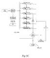
- FIG. 13is a third illustration of use of the embodiment of FIG. 1 .
- FIG. 14is an illustration of use of the embodiment of FIG. 8 .
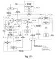
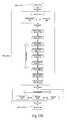
- FIG. 15is a diagrammatic illustration of an embodiment of software flow of software utilized by a microcontroller in the handheld controller.
- FIGS. 15A-Eprovide more specific embodiments of an implementation of the software flow embodiment of FIG. 15 .
- FIG. 1is a perspective view of a first embodiment of a handheld patient stimulator controller 100 .
- the controller 100comprises a base 102 , a bezel 104 , and a lens 106 , all of which, when assembled, form a protective shell 110 , which generally contains electronic circuitry.
- the base 102is generally a hollow, bowl-shaped component having a bottom 102 a and a continuous wall 102 b extending therefrom.
- the bezel 104has a first surface 104 a , which is desirably adapted to be placed and secured in a mating relationship to the base wall 102 b .
- the bezel 104may be secured to the base 102 by way of adhesive or even a locking physical structure, but more desirably by way of threaded fasteners.
- the bezel 104also has a second surface 104 b, which may be recessed, thereby providing a surface to which the lens 106 may anchor.
- Both the base 102 and the bezel 104are desirably molded to any desirable shape using injection molding of a suitable material such as Lustran® acrylonitrile-butadiene-styrene (ABS) 348 resin, or a polycarbonate ABS material that would allow thinner component construction and enhanced shock absorption.
- the lens 106has a first surface 106 a , which is adapted to rest against the bezel second surface 104 b .
- the lens first surface 106 amay be provided with an adhesive.
- the lens 106is desirably formed by injection molding of a material that can offer desired optical clarity.
- the shell 110is desirably appropriately sized to easily fit in a user's hand.
- a desirable shell 110may be about the size of other small personal electronic devices that may be about 7 centimeters long, about 4 centimeters wide, and about 1 centimeter thick.
- the user input interface 120desirably comprises a plurality of buttons; a power button 122 , a mode select pad 124 , and a parameter adjustment pad 126 .
- the power button 122is desirably a push button to power the controller 100 on and off.
- the mode select pad 124desirably provides two buttons; a mode up button 124 a and a mode down button 124 b .
- the adjustment pad 126also desirably provides two buttons; an increase button 126 a and a decrease button 126 b.
- buttons of the user input interface 120may be included as a part of the user input interface 120 , similar to the other buttons.
- the select buttoncould provide a means of affirmative indication by the user that a setting of the device 100 is acceptable.
- all buttons of the user input interface 120interface with at least one electronic component contained in the controller 100 .
- the buttonsare desirably injection molded silicone rubber.
- the controller 100comprises a user output interface 130 .
- the depicted controller 100is shown with a liquid crystal display (LCD) screen 131 as the user output interface 130 .
- the function of the user output interface 130is to provide some visual feedback such as a status or operating mode of the controller 100 , a status of a medical device, or a preview of programming parameters to be transferred to the medical device.
- LCDliquid crystal display
- Additional user output display componentsmay include other visual indicators such as simple light-emitting diodes (LEDs), or aural indicators such as piezo buzzers or variable audio tones.
- FIG. 2is a general exploded view of the controller 100 of FIG. 1 , showing the basic assembly of the controller 100 , and further showing a printed circuit assembly (PCA) 150 on which electronic circuitry contained in the shell 110 may be supported and interconnected.
- PCAprinted circuit assembly
- the controller 100may be supplied with at least one receptacle or port 140 for receiving plugs from external accessories or components.
- the one or more receptacles 140are electrically coupled to the appropriate electronic components. While a plurality of receptacles 140 could be provided, it is desirable to have only a single port 140 to allow the connection of only a single accessory at any given time. Where a single port 140 is meant to provide an interface for a variety of accessories, the port 140 and the accessory plugs may be keyed differently such that, by providing electrical contact surfaces in different locations in connection with the port 140 , the controller 100 is able to distinguish between connected accessories.
- the receptacle 140is desirably covered with a protective gasket 142 , which prevents the receptacle 140 from being contaminated with dust or other particulates, and may protect the receptacle 140 from exposure to moisture.
- the gasket 142is desirably injection molded out of any suitable material such as Santoprene® thermoplastic elastomer, available from Advanced Elastomer Systems, LP. The gasket 142 is held in place desirably by the clamping force holding the base 102 and bezel 104 together.
- FIG. 5diagrammatically depicts electrical components arranged, in no particular order, on the PCA 150 , shown in FIG. 2 , which is housed in the shell 110 .
- the controller 100desirably includes a power supply 152 , a programmable microcontroller 154 , an accessory controller 156 , a wireless telemetry module 158 , electrical connectors 157 , and user interface components 159 , all in operative electrical connection.
- the power supply 152may be a rechargeable battery 153 and associated charging and indication circuitry 155 .
- the rechargeable battery 153may be recharged when connected to a power source, such as when the controller 100 is connected by a power adaptor 300 to a wall outlet, or is docked on a docking station (not shown). Addressing safety concerns, the controller 100 desirably may not be used to recharge an IPG 18 while the controller 100 , itself, is being recharged through the power adaptor 300 .
- the charging and indication circuitry 155provides to the microcontroller 154 periodic updates of the status of the battery 153 and charging thereof.
- the battery 153is desirably secured in the shell so that it cannot be removed easily, so as to discourage accidental disposal by users.
- the programmable microcontroller 154provides the general intelligence of the controller 100 , and desirably includes a predetermined amount of memory to hold desirable software; however, the memory may also be supplied as a separate component.
- the microcontroller 154generally controls the operation of the user output interface 130 , the accessory controller 156 and the wireless telemetry module 158 , all depending upon the mode of operation as selected by the user input interface 120 or some other source.
- the accessory controller 156is desirably a slave to the microcontroller 154 and provides the requisite electronic control of an accessory, such as a charging coil 200 .
- the accessory controller 156is activated by the microcontroller 154 when the associated accessory is detected as being coupled to the controller 100 through the receptacle 140 .
- a single accessory controller 156may supply the requisite control of a plurality of accessories, or, alternatively, a plurality of accessory controllers 156 may be supplied.
- the telemetry module 158may incorporate a suitable wireless telemetry transceiver chip set that can operate in the Medical Implant Communications Service (MICS) band (402 MHz to 405 MHz) or other very high frequency (VHF) or ultra high frequency (UHF) low power, unlicensed bands.
- MIMSMedical Implant Communications Service
- VHFvery high frequency
- UHFultra high frequency
- a wireless telemetry link established between the controller 100 and an implanted medical deviceis especially useful in motor control applications where a user issues a command to an IPG to produce muscle contractions to achieve a functional goal (e.g., to stimulate ankle flexion to aid in the gait of an individual after a stroke).
- the wireless telemetryis desirably non-inductive radio frequency telemetry.
- a suitable transceiver chip that may be used for half duplex wireless communicationsis the AMIS-52100, available from AMI Semiconductor, Pocatello, Id. This transceiver chip is designed specifically for applications using the MICS band and the MICS European counter-part, the Ultra Low Power-Active Medical Implant (ULP-AMI) band.
- the electrical connectors 157 on the PCA 150may provide operative electrical interconnectivity between the PCA 150 and various electrical components, such as the LCD 131 , the receptacle 140 , other PCAs, or even a standardized test setup, such as a Joint Test Action Group (JTAG) interface.
- JTAGJoint Test Action Group
- User interface components 159convert user input to electrical signals to be used by the controller 100 and further convert electrical signals into indicators that are to be sensed by a user.
- As user interface components 160 to the user input interface 130it is desirable to provide a plurality of split electrical contacts 162 to indicate when a user has communicated through the user input interface 120 .
- the contacts 162are electrically coupled to the microcontroller 154 to indicate such user activity.
- An electrically conductive surfaceis provided on a bottom side of the plurality of buttons on the user input interface 120 , so as to connect both sides of the split contacts 162 when a button is depressed.
- the user interface components 160further comprise the parts of the user output interface 130 , such as the LCD 131 .
- FIG. 6shows the controller 100 with external accessories, which may include a charge coil 200 and a power adaptor 300 .
- the charge coil 200desirably includes a predetermined construction comprising a housing 202 , a coil cable 204 , and a winding (not shown).
- the housing 202is preferably formed to a desirable size out of a thermoplastic elastomer, such as Santoprene®. Such material aids in avoiding skin irritation that may arise as a result of long term exposure of a patient's skin to other materials.
- the windingcan be of various construction but is desirably 150 to 250 turns, and more desirably 200 turns, of six electrically parallel strands of #36 enameled magnetic wire, or the like.
- the charging coil outside diametermay be in a range of about 40 millimeters to about 70 millimeters, and desirably about 65 millimeters, although the diameter may vary.
- the thickness of the charging coil 104is desirably significantly less than its diameter, e.g., about three millimeters to about eleven millimeters, so as to allow the coil 200 to be embedded or laminated in the housing 202 to facilitate placement on or near the skin.
- Such a constructionallows for efficient power transfer and allows the charging coil 200 to maintain a safe operating temperature.
- the coil 200may be provided with an adhesive backing strip 208 to be removably coupled to a patient's skin.
- the strip 208may be formed of closed-cell polyethylene foam, which would prevent overheating of the patient's skin adjacent the coil 200 .
- the strip 208has a skin-side adhesive surface, which is desirably protected by a release liner 210 .
- the release liner 210prevents contamination of the adhesive strip 208 prior to application on the skin.
- the coil cable 204comprises insulated electrical conductors providing at least two conductive paths, operatively coupled to the coil winding at one end and to an electrical plug 206 at the other end. Therefore, one electrical path provides electrical current to the coil 200 while the other path provides a return current to the controller 100 .
- the electrical plug 206serves as the electrical connection point between the controller receptacle 140 and the coil 200 .
- the power adaptor 300provides the ability to recharge the controller battery 153 . It comprises a power plug 302 , converter 303 , and a power cord 304 .
- the power plug 302is a conventional power plug adapted to cooperate with any standard wall outlet socket.
- the converter 303receives alternating current power from the standard wall outlet socket, through the plug 302 , and presents the appropriate voltage required by the battery charging circuitry 155 in the controller 100 .
- the appropriate voltageis presented through the power cord 304 , which includes a power connector 306 , mateable with the controller receptacle 140 . Alternating current power cords are generally known in the art, and many variations are available.
- a second controller embodiment 400is shown in FIG. 8 .
- this controller 400has a user input interface 420 and a user output, or feedback, interface 430 .
- the user input interface 420comprises five buttons and a power switch 422 .
- the power switch 422 of this embodiment 400is desirably a single pole single throw slide switch 422 recessed below the outer surface of the controller shell 410 .
- the buttonsare divided into two pairs surrounding a center button 428 .
- One pair of buttonsdefines a mode pair 432 , 434 and the second pair of buttons defines an adjustment pair 442 , 444 .
- the center button. 428is desirably a general purpose “OK” or “Select” button. All buttons and switches of the user input interface 420 , are operationally coupled to at least some of the electronics contained in the controller 400 .
- the user output interface 430is provided desirably in the form of a plurality of light emitting diodes (LEDs) 431 - 435 .
- the LEDshave different display functionality depending upon the incident operating state of the electronic components within the controller 400 .
- the second embodiment 400contains various electronic components (not shown).
- the second embodiment 400desirably includes a non-rechargeable battery as its power supply and does not include an accessory controller. Therefore, the primary function of a reduced size controller, such as the second embodiment 400 , is the adjustment of stimulation parameters and monitoring of IPG status rather than recharging the IPG battery.
- the controller 100may take on any convenient shape, such as a ring on a finger, a watch on a wrist, or an attachment to a belt, for example. It may also be desirable to separate the functions of the controller 100 into a charger and a patient controller.
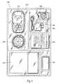
- FIG. 9depicts a controller kit 500 that may be provided in a packaging 510 and including a controller 100 , a charging coil 200 , a power adaptor 300 , a second controller 400 , a set of user instructions 520 , a carrying case 530 , record media 540 , and a remote device 600 .
- the remote device 600may be a simple magnet that enables transcutaneous activation and deactivation of an IPG 18 including magnetic controls, such as a reed switch.
- the record media 540may be paper or self-adhesive labels to be used by a patient or physician in conjunction with record keeping.
- the packaging 520can be made from any method now known in the art such as plastic molding.
- the kit 500may also be provided without the remote device 600 , the second controller 400 , the instructions 520 , the carrying case 530 or the record media 540 .
- the controller 100may be used with a variety of devices, the working example herein will concern use in conjunction with an implantable pulse generator (IPG) 18 .
- the IPG 18desirably incorporates a rechargeable battery that can be recharged transcutaneously and a non-inductive radio frequency (RF) wireless telemetry system to enable transcutaneous communication.
- RFradio frequency
- a patientmay control certain predefined parameters of the implantable pulse generator within a predefined limited range.
- the parametersmay include the operating modes/states, increasing/decreasing or optimizing stimulus patterns, or providing open or closed loop feedback from an external sensor or control source.
- Wireless telemetryalso desirably allows the user to interrogate the implantable pulse generator 18 as to the status of its internal battery.
- the full ranges within which these parameters may be adjusted by the userare desirably controlled, adjusted, and limited by a clinician, so the user may not be allowed the full range of possible adjustments. That is, while a given IPG parameter may be adjustable by a clinician over a number of settings, it is desirable that a patient have access to modify the parameters over only a limited range, less than the number of settings than a clinician has access to. Therefore, a clinician may develop a desirable treatment regimen for a given patient's condition and program the limited parameter range according to the treatment regimen.
- the rechargeable battery of the IPG 18may be recharged by the application of a transcutaneous low frequency RF magnetic field applied by a charging coil 200 mounted on a patient's skin or clothing and placed over or near the IPG 18 .
- the transcutaneous RF magnetic fieldmay have a frequency range of about 30 Khz to about 300 Khz.
- the charging coil 200is placed proximate the IPG 18 and connected by the coil cable 204 to the controller 100 , and electrically coupled to the accessory controller 156 through the controller receptacle 140 .
- the coil 200may be held in place manually, but it is desirable that the coil 200 be removably fastened to the skin by way of the adhesive backing strip ( 208 in FIG.
- the pouchbeing removably coupled to the skin.
- the pouchcould be coupled to a belt or other supporting structure, which is then worn by the user so as to properly position the coil 200 .
- FIG. 11portrays an alternative application, in which it is anticipated that a controller 100 may include an internal charging coil 200 .
- a user 1would then support or wear the controller 100 , which includes the internal charging coil 200 , over the IPG 18 to recharge the IPG 18 battery.
- the controller 100 and the IPG 18may also use wireless telemetry to provide a “smart charge” feature to indicate that charging is occurring and to make corrections to allow for optimal recharging and protect against overcharging.
- the smart chargecauses the controller 100 to issue commands to the IPG 18 at predetermined intervals, e.g., thirty seconds, to instruct the IPG 18 to confirm that the generated RF magnetic field is being received and is adequate for recharging the rechargeable battery. If the controller 100 does not receive a response from the IPG 18 to confirm that the generated RF magnetic field is being received, the controller 100 may stop generating the RF magnetic field.
- the IPG 18may transmit status information, such as an indication of the battery charge status and an indication of the magnitude of power recovered by the receive coil 200 , back to the controller 100 .
- the smart chargeallows the controller 100 to automatically adjust up or down the magnitude of the magnetic field and/or to instruct the user to reposition the charging coil 200 based on the status information to allow optimal recharging of the battery of the IPG 18 while minimizing unnecessary power consumption by the controller 100 and power dissipation in the IPG 18 (through circuit losses and/or through absorption by the implantable pulse generator case 20 and other components).
- the magnitude of the RF magnetic field 100may be automatically adjusted up to about 300 percent or more of the initial magnitude of the RF magnetic field and adjusted down until the controller 100 stops generating the RF magnetic field. Adjustment of the RF magnetic field 100 may also result from sensing a desirable temperature on the skin side of the charging coil 200 . That is, the magnitude may be increased or decreased if a sensed temperature is low enough or too high, respectively. Temperature sensing may be achieved by any general way known in the art, such as a thermistor or thermocouple.
- the instructions to the user to reposition the charging coil 200may be a visual instruction, such as a bar graph on the controller 100 , or a display on the controller 100 showing relative positions of the charging coil 200 and the IPG 18 , or an audio instruction, such as a varying tone to indicate relative position, or a combination of instructions.
- the IPG 18may incorporate wireless telemetry for a variety of functions, such as receipt and transmission of stimulus parameters and settings, receiving requests for and transmitting battery and operating status, allowing user control of the implantable pulse generator 18 , and for assisting in the control of the RF magnetic field generated by the controller 100 .
- each IPGmay have a unique signature that limits communication to only certain dedicated controllers. This signature could be a serial number that is stored in the IPG in non-volatile electronic memory or by other means. While an interface device or controller used by a clinician or physician may be configured for use with many patients and many IPGs by configuring the clinical programmer with various desired serial numbers, such broad functionality is not generally desirable for patients or caregivers.
- the controller 100is desirably the master of all wireless communications between it and an IPG 18 . Therefore, to begin a wireless communication, the controller 100 generates and sends a wireless telemetry communication to an IPG 18 , the communication including the IPG's unique serial number and data elements that indicate the communication is a command from an external controller 100 . Only the IPG 18 having the unique serial number responds to the communication from the controller 100 .
- the communication responseincludes elements that indicate the communication is a response to a command from an external controller 100 , and that the communication is not a command from a different external controller.
- Communications protocolsinclude appropriate received message integrity testing and message acknowledgment handshaking to assure the necessary accuracy and completeness of every message. Some operations (such as reprogramming or changing stimulus parameters) require rigorous message accuracy testing and acknowledgement. Other operations, such as a single user command value in a string of many consecutive values, might require less rigorous checking and no acknowledgement or a more loosely coupled acknowledgement. Integrity testing may be accomplished through the use of parity bits in the communication messages or even the use of a cyclic redundancy check (CRC) algorithm. Implementation of parity and CRC algorithms are generally known in the communications art.
- CRCcyclic redundancy check
- the timing with which an IPG enables its transceiver to search for RF telemetry from an external controllermay be precisely controlled (using a time base established by a quartz crystal) at a relatively low rate, e.g., the IPG may look for commands from the external controller for about two milliseconds at a rate of two (2) Hz or less. This equates to a monitoring interval of about 1 ⁇ 2 second or less. It is to be appreciated that an IPG's enabled transceiver rate and the monitoring rate may vary faster or slower depending on the application. This precise timing allows the external controller to synchronize its next command with the time that the IPG will be listening for commands.
- the communications sequencemay be configured to have the external controller issue commands in synchronization with the IPG listening for commands.
- the command set implementedmay be selected to minimize the number of messages necessary and the length of each message consistent with the appropriate level of error detection and message integrity monitoring. It is to be appreciated that the monitoring rate and level of message integrity monitoring may vary faster or slower depending on the application, and may vary over time within a given application.
- the wireless telemetry communicationsmay also be used in conjunction with the IPG battery charging function. It is especially useful in cases where two implant charger controllers 100 could be erroneously swapped, or where two or more IPGs 18 may be within wireless telemetry range of each other. For example, when two users live in the same home, a first IPG 18 could communicate with its controller 100 even when the charging coil 200 is erroneously positioned over another IPG 18 .
- the controller 100is configured to communicate and charge a specifically identified IPG, or a target IPG, which is identified by the unique signature or serial number. If the target IPG is wirelessly communicating with a controller 100 that is erroneously positioned, the target IPG communicates with the controller 100 to increase the magnitude of the RF magnetic field. This communication may continue until the magnitude of the RF magnetic field is at its maximum.
- the controller 100may periodically decrease the magnitude of the RF magnetic field and then wirelessly communicate with the target IPG 18 to determine whether the target IPG 18 sensed the decrease in the magnitude. If the charging coil 200 is erroneously positioned over an IPG other than the target IPG 18 , the target IPG 18 will not sense the decrease and will indicate to the controller 100 that it did not sense the decrease. The controller 100 will then restore the original RF magnetic field strength and retry the reduced RF magnetic field test. Multiple failures of the test may cause the controller 100 to suspend charging and notify the user 1 of the error. Similarly, should the IPG 18 not recover usable power from the RF magnetic field after a few minutes, the controller 100 will suspend charging and notify the user 1 of the error.
- the controller 100operates so as to provide an interface between an IPG and a patient in which the device is implanted, or a caregiver thereof.
- the controller 100provides the ability for the patient to recharge the IPG, query the IPG regarding its present settings, to adjust the IPG settings, and to recharge the controller 100 .
- an embodiment of the controller 100desirably has nine different operating modes: OFF, PROD_ID, IMP_STAT, REV_ADJ, LOC_COIL, IMP_CHG, CHG_DONE, CTRL_CHG, and SN_MOD.
- FIGS. 15A-Eprovide an exemplary software flow.
- the controller 100may enter the OFF mode from any other mode by a mere passage of time, or the user may affirmatively enter the OFF mode from any operating mode.
- controller power consumptionis minimal and the user output interface 130 is desirably deactivated.
- a simple “heartbeat” or other nominal indicationmay be shown on the output interface 130 to represent some state of the controller.
- the controller 100may enter the PROD_ID mode or the IMP_STAT mode.
- To enter the PROD_ID modethere are desirably two methods of removing the controller 100 from the OFF mode.
- a usercould depress the power button 122 . While depression of other buttons on the controller 100 could possibly turn the device 100 on, to minimize accidental activation, it is desirable that only one button, the power button 122 , activate the device 100 .
- the controller 100upon leaving the OFF mode, desirably enters the IMP_STAT mode with an error indicator displayed, as shown in one embodiment in FIG. 15E .
- PROD_IDThe controller 100 may enter the PROD_ID, or product identification, mode from the OFF mode.
- a temporary indicatorsuch as an informational screen, or “splash screen,” may be displayed, including information such as device information, manufacturer, software revision, date, time, etc. This screen or plurality of indicators remains active for a predetermined amount of time before entering the next mode.
- the controller 100may enter the following modes: IMP_STAT, LOC_COIL, or CTRL_CHG.
- the mode following the PROD_ID modedepends on whether an accessory is connected, and, if so, which accessory is connected. If no accessory is connected, the mode switches from PROD_ID to IMP_STAT. If the power adaptor 300 is connected through the controller receptacle 140 , the next mode is CTRL_CHG. Finally, if the charge coil 200 is connected through the controller receptacle 140 , the next mode is LOC_COIL.
- the controller 100may enter the IMP_STAT, or implant status, mode from the following modes: OFF, PROD_ID, REV_ADJ, LOC_COIL, IMP_CHG, or CTRL_CHG. If the controller 100 entered the OFF state during an error condition, powering on the controller 100 preferably places it in the IMP_STAT mode with an indication of the error state. Assuming no accessory is connected as the controller 100 is exiting the PROD_ID mode, the controller 100 enters the IMP_STAT mode.
- IMP_STATis entered by a mere passage of one of the following: a predetermined amount of time after REV_ADJ mode was entered; a predetermined amount of time after any parameter modifications are made; or, a predetermined amount of time after a predetermined combination of the mode buttons 124 a , 124 b are depressed.
- the controller 100may enter the IMP_STAT mode where a charge coil 200 is disconnected and fails to be reconnected within a predetermined amount of time.
- the controller 100enters the IMP_STAT mode if the power adaptor 300 is disconnected from the controller 100 .
- the predetermined amounts of timemay be anything greater than zero seconds, but is desirably between 3 and 30 seconds.
- the IMP_STAT modemay be a desirable base operating mode on top of which other modes may run.
- informationis displayed to the user. If the cause of entering this mode is a disconnected charge coil 200 , it is desirable to display an indication of the charge coil 200 disconnect that has occurred.
- the user output interface 130it is desirable to convey three pieces of information.
- One itemis the battery charge status of the controller 100 . The other two items depend on whether successful wireless communications can be established with the IPG 18 . If communications are not established, a message to that effect is desirably displayed. If communications can be established, the battery charge status of the IPG 18 is displayed, along with a present parameter setting, such as a stimulus intensity level. Rather than the three listed pieces of information, or in addition to that information, other status indicators or user commands could also be displayed through the user output interface 130 .
- the controllermay enter the following modes: OFF, REV_ADJ, LOC_COIL, and CTRL_CHG.
- the usermay do nothing, or may depress the power button 122 , for a predetermined period of time, and the controller 100 desirably proceeds to the OFF mode.
- the usermay depress a button on the mode select pad 124 to enter the REV_ADJ mode.
- the usermay connect a charge coil 200 to the controller receptacle 140 .
- the usermay connect a power adaptor 300 to the controller receptacle 140 and to an active wall socket to enter the CTRL_CHG mode.
- REV_ADJThe controller 100 may enter the REV_ADJ, or review and adjust settings, mode from the following modes: IMP_STAT or IMP_CHG. If the user is in either of these modes and depresses the mode select button 124 , the controller 100 will switch into the REV_ADJ mode.
- the userhas the option to adjust various settings both of the controller 100 and of the IPG 18 .
- the mode select button 124allows the user to scroll between parameters. For example, the user may wish to alter the volume of an audio indicator from the controller 100 . The user simply navigates to the volume parameter using the mode select button 124 and then changes the volume setting by using the parameter adjustment button 126 .
- Other parametersmay be adjusted, such as IPG stimulation intensity and IPG stimulation activation.
- the stimulation intensityis generally only a vague, abstract number to the patient. That is, the patient's physician will dictate the various stimulation profiles available to the patient through the use of the controller 100 in combination with the IPG 18 .
- the patientwill only see, desirably, a numerical indicator of which profile is activated and may possibly reference a correlative list of what those numerical indicators actually mean with regards to the technical settings of the IPG 18 , such as pulse width, amplitude and frequency of the stimulation. Therefore, as seen in FIG. 12 , the physician 2 may establish a “normal” or baseline stimulation level and the patient 1 may be able to adjust from the baseline plus or minus three steps, however those steps may be defined by the physician 2 . In the REV_ADJ mode, after the user has selected the desired value for the adjusted parameter, the controller 100 will indicate to the user that the parameter has been selected and is being transmitted to the IPG 18 .
- Such indicationcould be accomplished a variety of ways, such as specific iconic or textual displays, or even a simple change in the appearance of the screen, such as a flashing screen.
- the controller 100Upon communication of the changed parameters to the IPG 18 , or a predetermined amount of time thereafter, the controller 100 exits the REV_ADJ mode and returns to the IMP_STAT mode. The controller 100 may also exit the REV_ADJ mode after a predetermined input from the user input interface 120 . An embodiment of the flow through the REV_ADJ mode can be seen in FIG. 15B .
- an error messagemay be communicated through the user output interface 130 , as shown in FIG. 15D . The controller 100 may then attempt to restore communications with the IPG 18 .
- the controller 100may enter all of the modes from which the mode may have been entered: IMP_STAT or IMP_CHG.
- the mode to which the controller 100 proceedsdepends on which mode it was in before the REV_ADJ mode was entered. It may return to the mode from which it came by the mere passage of a predetermined period of inactivity, by the depression of the power button 122 .
- the controller 100may enter the LOC_COIL, or locate charging coil, mode from the following modes: PROD_ID, IMP_STAT or IMP_CHG. From the PROD_ID mode, if a charging coil 200 is coupled to the controller 100 , it enters the LOC_COIL mode automatically. From the IMP_STAT mode, rather than plug in the power adaptor 300 to the receptacle, the user could connect the charging coil 200 to the controller 100 causing it to enter the LOC_COIL mode. From the IMP_CHG mode, if the inductive coupling between the charge coil 200 and the IPG 18 becomes ineffective for purposes of charging, the controller 100 may be forced into the LOC_COIL mode. An implementation of the LOC_COIL mode can be seen in FIG. 15C .
- the screen 131displays a graphical indication of the quality of the charging coil 200 placement proximate the IPG 18 , and further includes an indicator, graphical or textual, that appears when the quality of the charging coil 200 placement is adequate to allow normal charging of the IPG battery. Desirably, depression of either the mode button 124 or the parameter adjustment button 126 has no effect on the controller 100 during the time it is locating the proper placement of the coil 200 . While maneuvering the coil 200 to locate the IPG 18 , and throughout charging, the user is informed as to the quality and status of the charging progress, desirably visually and aurally.
- the usershould especially be informed if the coil cable 204 becomes unplugged from the controller 100 . Once the locating tone and/or display indicate that the coil 200 is in proper charging position, the user can begin charging by pressing the power button 122 to enter the IMP_CHG mode.
- Two periods of inactivitywill cause the controller 100 to at least imply repositioning of the coil 200 and/or the controller 100 to enable proper charging.
- the controller 100warns the user of the lack of wireless communications with the IPG 18 .
- periodic updates of coil location qualityare calculated to provide adequate feedback to the user.
- the controller 100will not indicate to the user that placement of the coil 200 is adequate for normal charging.
- the controller 100may enter the following modes: OFF, IMP_STAT and IMP_CHG.
- the IMP_STAT modeis entered when a charge coil 200 is disconnected and fails to be reconnected within a predetermined amount of time.
- the IMP_CHG modeis entered when the user is satisfied with the positioning of the charging coil 200 and a triggering event occurs.
- the triggering eventcould be the depression of the power button 122 or the achievement of a predetermined charging power.
- the controllermay enter the IMP_CHG, or implant charging, mode from the following modes: LOC_COIL or REV_ADJ. Entry into this mode is caused by the occurrence of a triggering event.
- the triggering eventmay be a user-initiated event or an automatic reactive event.
- the user-initiated triggering eventmay be the depression of a button.
- the automatic reactive triggering eventmay be the mere passage of time, or even a sensed charge coil placement position.
- the IMP_CHG modedesirably runs on top of the IMP_STAT mode. Once in the IMP_CHG, an indication is displayed on the LCD 131 . While in this mode, the accessory controller 156 is driving the connected charging coil 200 . The user output interface 130 indicates to the user the fact that charging is taking place, and may also indicate the status of the IPG battery charge. While in this mode, the user may also alter the settings of the IPG 18 .
- the controller 100may enter the following modes of operation: OFF, IMP_STAT, REV_ADJ, LOC_COIL, CHG_DONE, or CTRL_CHG.
- the usermay affirmatively cancel the charging process, in which case the controller 100 desirably enters the OFF mode or IMP_STAT mode.
- Depression of the mode select button 124will cause the controller 100 to enter the REV_ADJ mode and provide indication to the user.
- the IMP_CHG modecompletes when the IPG is fully charged or when the charge in the controller battery 153 is insufficient to continue adequate charging.
- the controller 100enters the CHG_DONE mode.
- the controller 100may enter the CHG_DONE, or charge done, mode from the IMP_CHG mode.
- the CHG_DONE modeis entered upon the occurrence of either a completely charged IPG 18 battery or upon the depletion of the controller battery 153 to a point where further implant charging would be ineffective. Desirably, although continued IPG charging may not be allowed, the depletion point would allow enough controller battery 153 charge to allow basic operation of the controller 100 .
- the controller 100may proceed to the following modes: OFF or IMP_STAT.
- the power button 122is depressed for a predetermined period of time, or the controller could enter the OFF mode after a predetermined period of inactivity.
- the charge coilis removed from the controller 100 , it enters the IMP_STAT mode.
- CTRL_CHGThe controller 100 may enter the CTRL_CHG mode from the following modes: PROD_ID, IMP_STAT or IMP_CHG. Entering from either PROD_ID or IMP_STAT mode occurs if power is supplied to the controller 100 by a connected power adaptor 300 .
- the CTRL_CHG modeis entered from the IMP_CHG mode if the power adaptor 300 is coupled to the controller 100 within a predetermined amount of time from a disconnection of the charge coil 200 . In this case, the unplugged coil 200 status may be communication through the user output interface 130 prior to entering the CTRL_CHG mode.
- an indicatoris displayed to the user through the user output interface 130 .
- the indicatormay be a separate screen, or simply an indicator displayed in combination with other screens.
- the indication providedmay be that of the present controller battery 153 level and an indication that the battery is charging.
- the controller 100may enter the following modes: OFF, IMP_STAT, or SN_MOD.
- the controller 100enters the OFF mode if the power button 122 is depressed for a predetermined amount of time.
- the IMP_STAT modeis entered when the power adaptor 300 is disconnected from the controller 100 , or when the controller battery 153 has been charged to a predetermined level.
- the controller 100enters the SN_MOD mode when a certain combination of buttons is pressed.
- the controller 100may enter the SN_MOD, or serial number modification, mode from the CTRL_CHG mode.
- the SN_MOD modeis entered by depressing a certain combination of buttons on the face of the controller 100 within a predetermined time. This mode is desirably not available to the patient or caregiver and is supplied primarily for maintenance of the device or review of the device settings by a supervising physician.
- the physicianmay modify the serial number of the IPG with which the controller 100 should be communicating. This modification is accomplished by using the user input interface 120 and the user output interface 130 .
- the controller 100may enter either the OFF mode or the CTRL_CHG mode.
- the physicianmerely depresses the power button 122 for a predetermined period of time. If the power button 122 remains unpressed for a period of time, the controller 100 desirably returns to the CTRL_CHG mode from which it came to enter the SN_MOD mode.
- a userturns the controller 400 on with the power switch 422 to communicate with an IPG 18 .
- the userhas the ability to switch modes using the mode up button 424 a and the mode down button 424 b .
- Desirable modesare (1) query present setting of IPG 18 , (2) change stimulation setting of the IPG 18 , (3) query battery level of the IPG 18 , and (4) query battery level of the controller 400 .
- the default modeis mode 1 .
- the current modeis reflected by a predetermined patterned flash or constant light of the first LED 431 .
- the userpresses the center button 428 .
- the user feedback interface 430displays the result of the query.
- the LED corresponding to the current IPG settingwill flash a predetermined number of times.
- the user output interface 430will then display the mode it is in by maintaining an LED 431 lit.
- the user 1can scroll through the modes using the mode up button 424 a or mode down button 424 b .
- mode 2the user 1 can alter the stimulation profile with the profile up button 426 a or profile down button 426 b .
- the second LED 432flashes a predetermined number times, and then the LED corresponding to the current IPG setting illuminates steady for a predetermined amount of time. While the present setting LED remains illuminated, the user 1 may propose a new IPG setting by using the profile up button 426 a or profile down button 426 b .
- the proposed setting LEDflashes. For example, if the IPG 18 is currently set to stimulation profile 3 , the third LED 433 will remain lit. If the user 1 hits the profile up button 426 a , the fourth LED 434 will flash and the 3rd will remain lit. If, instead, the user 1 hits the profile down button 426 b , the second LED 432 will flash and the third 433 will remain lit.
- the user 1may hit the mode down button 424 b , which serves as a “Back” function. If the user 1 wishes to continue to the new setting, indicated by the flashing LED, the user can hit the center button 428 , which serves as an “OK” function.
- the LEDswhen the IPG battery power is queried, the LEDs would illuminate from left to right indicating percentage of battery life remaining. Thus, to indicate 80% IPG battery life, the four leftmost LEDs would illuminate. To indicate 40% IPG battery life, the two leftmost LEDs would illuminate. The LEDs would switch off at the earlier of a predetermined time or the turning off of the power switch.
- FIG. 13contemplates control of the handheld controller 100 by a remote computer 700 over an operative connection 702 .
- the operative connection 702may be a packet switched connection established over a local area network connection, a wide area network connection, a wireless network connection, an internet connection.
- the operative connection 702may be a more direct connection such as a serial RS-232 cable or USB cable.
- a supervising physician or other person with accessmay reprogram the handheld controller 100 or even query and modify parameters of an implanted medical device 18 .
Landscapes
- Engineering & Computer Science (AREA)
- Health & Medical Sciences (AREA)
- Biomedical Technology (AREA)
- Nuclear Medicine, Radiotherapy & Molecular Imaging (AREA)
- Radiology & Medical Imaging (AREA)
- Life Sciences & Earth Sciences (AREA)
- Animal Behavior & Ethology (AREA)
- General Health & Medical Sciences (AREA)
- Public Health (AREA)
- Veterinary Medicine (AREA)
- Computer Networks & Wireless Communication (AREA)
- Physics & Mathematics (AREA)
- Power Engineering (AREA)
- General Physics & Mathematics (AREA)
- Human Computer Interaction (AREA)
- Electromagnetism (AREA)
- Acoustics & Sound (AREA)
- Multimedia (AREA)
- Signal Processing (AREA)
- Electrotherapy Devices (AREA)
- Heart & Thoracic Surgery (AREA)
- Neurology (AREA)
Abstract
Description
Claims (36)
Priority Applications (6)
| Application Number | Priority Date | Filing Date | Title |
|---|---|---|---|
| US11/712,379US9480846B2 (en) | 2006-05-17 | 2007-02-28 | Systems and methods for patient control of stimulation systems |
| EP07777090.7AEP2029219B1 (en) | 2006-05-17 | 2007-05-16 | Implantable pulse generator systems |
| PCT/US2007/011735WO2007136657A2 (en) | 2006-05-17 | 2007-05-16 | Implantable pulse generator systems and methods for providing stimulation |
| EP08726120AEP2129427A4 (en) | 2007-02-28 | 2008-02-26 | Systems and methods for patient control of stimulation systems |
| PCT/US2008/002540WO2008106138A1 (en) | 2007-02-28 | 2008-02-26 | Systems and methods for patient control of stimulation systems |
| US15/339,596US10322287B2 (en) | 2006-05-17 | 2016-10-31 | Systems and methods for patient control of stimulation systems |
Applications Claiming Priority (3)
| Application Number | Priority Date | Filing Date | Title |
|---|---|---|---|
| US80100306P | 2006-05-17 | 2006-05-17 | |
| US11/516,890US20070060967A1 (en) | 2004-06-10 | 2006-09-07 | Implantable pulse generator systems and methods for providing functional and /or therapeutic stimulation of muscles and/or nerves and/or central nervous system tissue |
| US11/712,379US9480846B2 (en) | 2006-05-17 | 2007-02-28 | Systems and methods for patient control of stimulation systems |
Related Parent Applications (1)
| Application Number | Title | Priority Date | Filing Date |
|---|---|---|---|
| US11/516,890Continuation-In-PartUS20070060967A1 (en) | 2004-06-10 | 2006-09-07 | Implantable pulse generator systems and methods for providing functional and /or therapeutic stimulation of muscles and/or nerves and/or central nervous system tissue |
Related Child Applications (1)
| Application Number | Title | Priority Date | Filing Date |
|---|---|---|---|
| US15/339,596DivisionUS10322287B2 (en) | 2006-05-17 | 2016-10-31 | Systems and methods for patient control of stimulation systems |
Publications (2)
| Publication Number | Publication Date |
|---|---|
| US20070270921A1 US20070270921A1 (en) | 2007-11-22 |
| US9480846B2true US9480846B2 (en) | 2016-11-01 |
Family
ID=39758737
Family Applications (2)
| Application Number | Title | Priority Date | Filing Date |
|---|---|---|---|
| US11/712,379Active2028-11-16US9480846B2 (en) | 2006-05-17 | 2007-02-28 | Systems and methods for patient control of stimulation systems |
| US15/339,596Expired - Fee RelatedUS10322287B2 (en) | 2006-05-17 | 2016-10-31 | Systems and methods for patient control of stimulation systems |
Family Applications After (1)
| Application Number | Title | Priority Date | Filing Date |
|---|---|---|---|
| US15/339,596Expired - Fee RelatedUS10322287B2 (en) | 2006-05-17 | 2016-10-31 | Systems and methods for patient control of stimulation systems |
Country Status (3)
| Country | Link |
|---|---|
| US (2) | US9480846B2 (en) |
| EP (1) | EP2129427A4 (en) |
| WO (1) | WO2008106138A1 (en) |
Cited By (45)
| Publication number | Priority date | Publication date | Assignee | Title |
|---|---|---|---|---|
| US20160170776A1 (en)* | 2013-04-30 | 2016-06-16 | Sca Hygiene Products Ab | Event-driven transitions in absorbent article management |
| US20160175600A1 (en)* | 2014-12-22 | 2016-06-23 | Newpace Ltd. | Wireless recharging system and method for flexible implantable subcutaneous medical device |
| US20170143983A1 (en)* | 2006-05-17 | 2017-05-25 | Medtronic Urinary Solutions, Inc. | Systems and methods for patient control of stimulation systems |
| US9724526B2 (en) | 2004-06-10 | 2017-08-08 | Medtronic Urinary Solutions, Inc. | Implantable pulse generator systems and methods for operating the same |
| USD797949S1 (en)* | 2016-02-12 | 2017-09-19 | Axonics Modulation Technologies, Inc. | Patient remote |
| US10556112B1 (en) | 2013-11-07 | 2020-02-11 | Nevro Corp. | Spinal cord modulation for inhibiting pain via short pulse width waveforms, and associated systems and methods |
| US10603494B2 (en) | 2009-04-22 | 2020-03-31 | Nevro Corp. | Selective high frequency spinal cord modulation for inhibiting pain with reduced side effects, and associated systems and methods |
| US10751536B1 (en) | 2013-06-10 | 2020-08-25 | Nevro Corp. | Methods and systems for disease treatment using electrical stimulation |
| US10850104B2 (en) | 2015-07-10 | 2020-12-01 | Axonics Modulation Technologies, Inc. | Implantable nerve stimulator having internal electronics without ASIC and methods of use |
| US10918867B2 (en) | 2009-01-29 | 2021-02-16 | Nevro Corp. | Systems and methods for producing asynchronous neural responses to treat pain and/or other patient conditions |
| US10971950B2 (en) | 2013-07-29 | 2021-04-06 | The Alfred E. Mann Foundation For Scientific Research | Microprocessor controlled class E driver |
| US11083903B2 (en) | 2016-01-29 | 2021-08-10 | Axonics, Inc. | Methods and systems for frequency adjustment to optimize charging of implantable neurostimulator |
| US11100737B1 (en)* | 2020-01-19 | 2021-08-24 | Intellishot Holdings Inc. | Biometric sensor |
| US11110283B2 (en) | 2018-02-22 | 2021-09-07 | Axonics, Inc. | Neurostimulation leads for trial nerve stimulation and methods of use |
| US11116985B2 (en) | 2014-08-15 | 2021-09-14 | Axonics, Inc. | Clinician programmer for use with an implantable neurostimulation lead |
| US11123569B2 (en) | 2015-01-09 | 2021-09-21 | Axonics, Inc. | Patient remote and associated methods of use with a nerve stimulation system |
| US11213675B2 (en) | 2014-08-15 | 2022-01-04 | Axonics, Inc. | Implantable lead affixation structure for nerve stimulation to alleviate bladder dysfunction and other indication |
| US11229792B2 (en) | 2009-04-22 | 2022-01-25 | Nevro Corp. | Spinal cord modulation for inducing paresthetic and anesthetic effects, and associated systems and methods |
| US11247057B1 (en) | 2012-06-22 | 2022-02-15 | Nevro Corp. | Autonomic nervous system control via high frequency spinal cord modulation, and associated systems and methods |
| US11260236B2 (en) | 2016-02-12 | 2022-03-01 | Axonics, Inc. | External pulse generator device and affixation device for trial nerve stimulation and methods of use |
| US11298539B2 (en) | 2011-09-08 | 2022-04-12 | Nevro Corp. | Selective high frequency spinal cord modulation for inhibiting pain, including cephalic and/or total body pain with reduced side effects, and associated systems and methods |
| US11318310B1 (en) | 2015-10-26 | 2022-05-03 | Nevro Corp. | Neuromodulation for altering autonomic functions, and associated systems and methods |
| US11338144B2 (en) | 2013-03-15 | 2022-05-24 | Alfred E. Mann Foundation For Scientific Research | Current sensing multiple output current stimulators |
| USD952862S1 (en) | 2020-04-02 | 2022-05-24 | Scosche Industries, Inc. | Health sensor |
| USD957648S1 (en)* | 2018-10-12 | 2022-07-12 | Masimo Corporation | Dongle |
| US11389659B2 (en) | 2014-08-15 | 2022-07-19 | Axonics, Inc. | External pulse generator device and associated methods for trial nerve stimulation |
| US11439829B2 (en) | 2019-05-24 | 2022-09-13 | Axonics, Inc. | Clinician programmer methods and systems for maintaining target operating temperatures |
| US11478648B2 (en) | 2015-01-09 | 2022-10-25 | Axonics, Inc. | Antenna and methods of use for an implantable nerve stimulator |
| US11484723B2 (en) | 2015-01-09 | 2022-11-01 | Axonics, Inc. | Attachment devices and associated methods of use with a nerve stimulation charging device |
| US11502545B2 (en)* | 2020-05-29 | 2022-11-15 | Puthalath Koroth Raghuprasad | Watch charging assembly |
| US11497916B2 (en) | 2014-08-15 | 2022-11-15 | Axonics, Inc. | Electromyographic lead positioning and stimulation titration in a nerve stimulation system for treatment of overactive bladder |
| US11590352B2 (en) | 2019-01-29 | 2023-02-28 | Nevro Corp. | Ramped therapeutic signals for modulating inhibitory interneurons, and associated systems and methods |
| US11596798B2 (en) | 2016-01-25 | 2023-03-07 | Nevro Corp | Treatment of congestive heart failure with electrical stimulation, and associated systems and methods |
| US11631307B2 (en) | 2020-05-15 | 2023-04-18 | Intellishot Holdings Inc | Invisible acoustic safe |
| US11642537B2 (en) | 2019-03-11 | 2023-05-09 | Axonics, Inc. | Charging device with off-center coil |
| USD989327S1 (en) | 2018-10-12 | 2023-06-13 | Masimo Corporation | Holder |
| US11730411B2 (en) | 2014-08-15 | 2023-08-22 | Axonics, Inc. | Methods for determining neurostimulation electrode configurations based on neural localization |
| US11848090B2 (en) | 2019-05-24 | 2023-12-19 | Axonics, Inc. | Trainer for a neurostimulator programmer and associated methods of use with a neurostimulation system |
| USD1013179S1 (en)* | 2018-10-12 | 2024-01-30 | Masimo Corporation | Sensor device |
| US12070293B2 (en) | 2016-07-07 | 2024-08-27 | Masimo Corporation | Wearable pulse oximeter and respiration monitor |
| US12176100B2 (en) | 2021-08-23 | 2024-12-24 | Pacesetter, Inc. | System and method for implantable medical device remote programming |
| US12257022B2 (en) | 2018-10-12 | 2025-03-25 | Masimo Corporation | System for transmission of sensor data using dual communication protocol |
| US12268876B2 (en) | 2005-09-26 | 2025-04-08 | Flathead Partners, Llc | Neural blocking therapy |
| US12420103B1 (en) | 2020-08-20 | 2025-09-23 | Axonics, Inc. | Neurostimulation leads with reduced current leakage |
| US12440128B2 (en) | 2022-12-23 | 2025-10-14 | Masimo Corporation | Wrist and finger worn pulse oximetry system |
Families Citing this family (58)
| Publication number | Priority date | Publication date | Assignee | Title |
|---|---|---|---|---|
| US7761167B2 (en) | 2004-06-10 | 2010-07-20 | Medtronic Urinary Solutions, Inc. | Systems and methods for clinician control of stimulation systems |
| US8068918B2 (en) | 2007-03-09 | 2011-11-29 | Enteromedics Inc. | Remote monitoring and control of implantable devices |
| US8532787B2 (en) | 2007-05-31 | 2013-09-10 | Enteromedics Inc. | Implantable therapy system having multiple operating modes |
| US8131377B2 (en)* | 2007-07-11 | 2012-03-06 | Boston Scientific Neuromodulation Corporation | Telemetry listening window management for an implantable medical device |
| AU2012244268B2 (en)* | 2007-11-05 | 2014-06-05 | Boston Scientific Neuromodulation Corporation | External controller for an implantable medical device system with coupleable external charging coil assembly |
| US8498716B2 (en)* | 2007-11-05 | 2013-07-30 | Boston Scientific Neuromodulation Corporation | External controller for an implantable medical device system with coupleable external charging coil assembly |
| DK2231268T5 (en)* | 2007-12-21 | 2014-06-30 | Neurodan As | Mechanical control of an electrical nerve stimulation system for the treatment of pelvic related disorders |
| US8301236B2 (en)* | 2009-05-22 | 2012-10-30 | Biomedical Systems Corporation | System and method for high resolution wireless full disclosure ECG episode monitoring and analysis |
| US20100318159A1 (en)* | 2009-06-12 | 2010-12-16 | Boston Scientific Neuromodulation Corporation | Miniature remote controller for implantable medical device |
| US8594806B2 (en) | 2010-04-30 | 2013-11-26 | Cyberonics, Inc. | Recharging and communication lead for an implantable device |
| WO2012087819A2 (en) | 2010-12-20 | 2012-06-28 | Abiomed, Inc. | Transcutaneous energy transfer system with vibration inducing warning circuitry |
| JP2014502528A (en) | 2010-12-20 | 2014-02-03 | アビオメド インコーポレイティド | Method and apparatus for accurately tracking charge available in a transdermal energy transmission system |
| DK2654878T3 (en) | 2010-12-20 | 2019-07-22 | Abiomed Inc | TRANSCUTANT ENERGY TRANSFER SYSTEM WITH A MULTIPLE OF SECONDARY COILS |
| EP2697890B1 (en)* | 2011-04-14 | 2019-02-20 | Abiomed, Inc. | Transcutaneous energy transfer coil with integrated radio frequency antenna |
| US20130197607A1 (en) | 2011-06-28 | 2013-08-01 | Greatbatch Ltd. | Dual patient controllers |
| US20130006330A1 (en) | 2011-06-28 | 2013-01-03 | Greatbatch, Ltd. | Dual patient controllers |
| US8954148B2 (en) | 2011-06-28 | 2015-02-10 | Greatbatch, Ltd. | Key fob controller for an implantable neurostimulator |
| US8700175B2 (en) | 2011-07-19 | 2014-04-15 | Greatbatch Ltd. | Devices and methods for visually indicating the alignment of a transcutaneous energy transfer device over an implanted medical device |
| US8668345B2 (en) | 2011-11-30 | 2014-03-11 | Izi Medical Products | Retro-reflective marker with snap on threaded post |
| US9002468B2 (en) | 2011-12-16 | 2015-04-07 | Abiomed, Inc. | Automatic power regulation for transcutaneous energy transfer charging system |
| WO2013095799A1 (en) | 2011-12-21 | 2013-06-27 | Boston Scientific Neuromodulation Corporation | A system for an implantable medical device having an external charger coupleable to accessory charging coils |
| US9270134B2 (en)* | 2012-01-27 | 2016-02-23 | Medtronic, Inc. | Adaptive rate recharging system |
| US10682520B2 (en) | 2012-01-27 | 2020-06-16 | Medtronic, Inc. | Managing recharge power for implantable medical devices |
| US8661573B2 (en) | 2012-02-29 | 2014-03-04 | Izi Medical Products | Protective cover for medical device having adhesive mechanism |
| US9649165B2 (en)* | 2012-07-16 | 2017-05-16 | Cardiac Innovation, Llc | Medical device identifier |
| US8886333B2 (en) | 2012-07-19 | 2014-11-11 | Boston Scientific Neuromodulation Corporation | Self-affixing external charging system for an implantable medical device |
| US9343923B2 (en) | 2012-08-23 | 2016-05-17 | Cyberonics, Inc. | Implantable medical device with backscatter signal based communication |
| US9935498B2 (en) | 2012-09-25 | 2018-04-03 | Cyberonics, Inc. | Communication efficiency with an implantable medical device using a circulator and a backscatter signal |
| US9390619B1 (en)* | 2013-03-12 | 2016-07-12 | Smiths Detection-Watford Limited | Accessory for controlling activation of a device |
| US9867991B2 (en) | 2013-07-31 | 2018-01-16 | Nevro Corp. | Physician programmer with enhanced graphical user interface, and associated systems and methods |
| JP6640084B2 (en)* | 2013-08-09 | 2020-02-05 | インスパイア・メディカル・システムズ・インコーポレイテッドInspire Medical Systems, Inc. | Patient management system |
| GB2533503B (en)* | 2013-08-19 | 2020-09-16 | Fisher & Paykel Healthcare Ltd | A user interface and method of operating same |
| US9700227B2 (en)* | 2013-09-25 | 2017-07-11 | Bardy Diagnostics, Inc. | Ambulatory electrocardiography monitoring patch optimized for capturing low amplitude cardiac action potential propagation |
| EP3131601B1 (en) | 2014-04-15 | 2018-07-25 | Heartware, Inc. | Improvements in transcutaneous energy transfer systems |
| US9713453B2 (en)* | 2014-07-16 | 2017-07-25 | Neocoil, Llc | Method and apparatus for high reliability wireless communications |
| USD752763S1 (en) | 2014-08-08 | 2016-03-29 | Inspire Medical Systems, Inc. | Patient control |
| US9929584B2 (en) | 2014-10-30 | 2018-03-27 | Boston Scientific Neuromodulation Corporation | External charging coil assembly for charging a medical device |
| FR3031892A1 (en)* | 2015-01-23 | 2016-07-29 | Deleo | TOGETHER FOR NON-INVASIVE FATTY TREATMENT OF FATS BY COLD |
| US10105545B2 (en) | 2015-03-12 | 2018-10-23 | Boston Scientific Neuromodulation Corporation | Assembly with a coaxial audio connector for charging an implantable medical device |
| US9517344B1 (en) | 2015-03-13 | 2016-12-13 | Nevro Corporation | Systems and methods for selecting low-power, effective signal delivery parameters for an implanted pulse generator |
| US10300277B1 (en) | 2015-12-14 | 2019-05-28 | Nevro Corp. | Variable amplitude signals for neurological therapy, and associated systems and methods |
| USD801538S1 (en) | 2015-12-16 | 2017-10-31 | Inspire Medical Systems, Inc. | Patient control |
| USD810306S1 (en) | 2016-03-24 | 2018-02-13 | Inspire Medical Systems, Inc. | Patient control |
| EP3648833B1 (en)* | 2017-06-29 | 2021-08-04 | Hemoref, Inc. | Device using electrotherapy for the relief of hemorrhoid inflammation |
| US10589089B2 (en) | 2017-10-25 | 2020-03-17 | Epineuron Technologies Inc. | Systems and methods for delivering neuroregenerative therapy |
| CA3079849A1 (en) | 2017-10-25 | 2019-05-02 | Epineuron Technologies Inc. | Systems and methods for delivering neuroregenerative therapy |
| CN110314283A (en)* | 2018-03-28 | 2019-10-11 | 苏州景昱医疗器械有限公司 | A kind of method and apparatus of creation wireless communication |
| USD875691S1 (en)* | 2018-11-21 | 2020-02-18 | Shenzhen Chuse Beauty Management Co, Ltd. | Power controller |
| GB2580330B (en)* | 2018-12-31 | 2021-01-20 | Emda Ltd | Device to electromagnetically stimulate new organic cell proliferation |
| USD932637S1 (en)* | 2019-07-12 | 2021-10-05 | Raymond Hsu | TENS device |
| BR112022005384A2 (en)* | 2019-09-23 | 2022-06-21 | E Bio Corp | Electrical muscle controller system for monitoring and modulating uterine contraction |
| US11247043B2 (en) | 2019-10-01 | 2022-02-15 | Epineuron Technologies Inc. | Electrode interface devices for delivery of neuroregenerative therapy |
| US11883675B2 (en) | 2019-12-20 | 2024-01-30 | Medtronic, Inc. | Transcutaneous energy transfer system including alarm |
| US11051908B1 (en) | 2020-05-29 | 2021-07-06 | David Newsham | Patient anxiety management system and method of use |
| US11794020B2 (en) | 2021-01-11 | 2023-10-24 | Bardy Diagnostics, Inc. | System and method for data exchange and charging |
| USD1010831S1 (en) | 2021-02-23 | 2024-01-09 | Inspire Medical Systems, Inc. | Patient control |
| US20220271575A1 (en)* | 2021-02-24 | 2022-08-25 | Medtronic, Inc. | Learning algorithm for recharge system |
| USD989972S1 (en)* | 2021-07-02 | 2023-06-20 | Haifei Long | Transcutaneous electrical nerve muscle stimulation device |
Citations (287)
| Publication number | Priority date | Publication date | Assignee | Title |
|---|---|---|---|---|
| US3421511A (en) | 1965-12-10 | 1969-01-14 | Medtronic Inc | Implantable electrode for nerve stimulation |
| US3654933A (en) | 1968-11-18 | 1972-04-11 | Medtronic Inc | Implatable electrode |
| US3727616A (en) | 1971-06-15 | 1973-04-17 | Gen Dynamics Corp | Electronic system for the stimulation of biological systems |
| US3774618A (en) | 1972-07-03 | 1973-11-27 | Avery Labor Inc | Implantable nerve stimulation electrode |
| US3870051A (en) | 1972-04-27 | 1975-03-11 | Nat Res Dev | Urinary control |
| US3902501A (en) | 1973-06-21 | 1975-09-02 | Medtronic Inc | Endocardial electrode |
| US3926198A (en) | 1974-06-10 | 1975-12-16 | Arco Med Prod Co | Cardiac pacer |
| US3939843A (en) | 1974-03-04 | 1976-02-24 | Medtronic, Inc. | Transvenous electrode |
| US3939841A (en) | 1974-03-06 | 1976-02-24 | Dohring Albert A | Acupuncture needle guide and restraint |
| US3941136A (en) | 1973-11-21 | 1976-03-02 | Neuronyx Corporation | Method for artificially inducing urination, defecation, or sexual excitation |
| US3943932A (en) | 1975-01-17 | 1976-03-16 | Yen Kong Woo | Acupuncture needles and holder |
| US3943938A (en) | 1974-02-27 | 1976-03-16 | Paul Wexler | Anal sphincter device and barium enema plug |
| US4232679A (en) | 1977-01-26 | 1980-11-11 | Pacesetter Systems, Inc. | Programmable human tissue stimulator |
| US4254775A (en) | 1979-07-02 | 1981-03-10 | Mieczyslaw Mirowski | Implantable defibrillator and package therefor |
| US4257423A (en) | 1978-11-06 | 1981-03-24 | Medtronic, Inc. | Medical device |
| US4262678A (en) | 1979-06-28 | 1981-04-21 | Medtronic, Inc. | Pacing lead with tine protector |
| US4398545A (en) | 1979-10-10 | 1983-08-16 | Cyclotechnical Medical Industries, Inc. | Pain-blocking bandage |
| US4406288A (en) | 1981-04-06 | 1983-09-27 | Hugh P. Cash | Bladder control device and method |
| US4407303A (en) | 1980-04-21 | 1983-10-04 | Siemens Aktiengesellschaft | Endocardial electrode arrangement |
| US4512351A (en) | 1982-11-19 | 1985-04-23 | Cordis Corporation | Percutaneous lead introducing system and method |
| US4519404A (en) | 1983-09-28 | 1985-05-28 | Fleischhacker John J | Endocardial electrode lead with conical fixation mechanism |
| US4569351A (en) | 1984-12-20 | 1986-02-11 | University Of Health Sciences/The Chicago Medical School | Apparatus and method for stimulating micturition and certain muscles in paraplegic mammals |
| US4573481A (en) | 1984-06-25 | 1986-03-04 | Huntington Institute Of Applied Research | Implantable electrode array |
| US4585005A (en) | 1984-04-06 | 1986-04-29 | Regents Of University Of California | Method and pacemaker for stimulating penile erection |
| US4585013A (en) | 1981-04-20 | 1986-04-29 | Cordis Corporation | Lumenless pervenous electrical lead and method of implantation |
| US4590689A (en) | 1984-08-30 | 1986-05-27 | Vynalam, Ltd. | Air-trapping insoles |
| US4590946A (en) | 1984-06-14 | 1986-05-27 | Biomed Concepts, Inc. | Surgically implantable electrode for nerve bundles |
| US4592360A (en) | 1980-10-09 | 1986-06-03 | Cordis Corporation | Implantable externally programmable microprocessor-controlled tissue stimulator |
| US4602624A (en) | 1984-10-11 | 1986-07-29 | Case Western Reserve University | Implantable cuff, method of manufacture, and method of installation |
| US4607639A (en) | 1984-05-18 | 1986-08-26 | Regents Of The University Of California | Method and system for controlling bladder evacuation |
| US4628942A (en) | 1984-10-11 | 1986-12-16 | Case Western Reserve University | Asymmetric shielded two electrode cuff |
| US4649936A (en) | 1984-10-11 | 1987-03-17 | Case Western Reserve University | Asymmetric single electrode cuff for generation of unidirectionally propagating action potentials for collision blocking |
| US4658515A (en) | 1985-02-05 | 1987-04-21 | Oatman Donald S | Heat insulating insert for footwear |
| US4703755A (en) | 1984-05-18 | 1987-11-03 | The Regents Of The University Of California | Control system for the stimulation of two bodily functions |
| US4716888A (en) | 1985-06-17 | 1988-01-05 | Cordis Corporation | Tined leads |
| US4721118A (en) | 1981-04-20 | 1988-01-26 | Cordis Leads, Inc. | Pervenous electrical pacing lead with foldable fins |
| US4739764A (en) | 1984-05-18 | 1988-04-26 | The Regents Of The University Of California | Method for stimulating pelvic floor muscles for regulating pelvic viscera |
| US4741341A (en) | 1986-03-12 | 1988-05-03 | Siemens-Pacesetter, Inc. | Protection circuit and method for implanted ECG telemetry circuits |
| US4750499A (en) | 1986-08-20 | 1988-06-14 | Hoffer Joaquin A | Closed-loop, implanted-sensor, functional electrical stimulation system for partial restoration of motor functions |
| US4771779A (en) | 1984-05-18 | 1988-09-20 | The Regents Of The University Of California | System for controlling bladder evacuation |
| US4793353A (en) | 1981-06-30 | 1988-12-27 | Borkan William N | Non-invasive multiprogrammable tissue stimulator and method |
| US4835372A (en) | 1985-07-19 | 1989-05-30 | Clincom Incorporated | Patient care system |
| US4920979A (en) | 1988-10-12 | 1990-05-01 | Huntington Medical Research Institute | Bidirectional helical electrode for nerve stimulation |
| US4926875A (en) | 1988-01-25 | 1990-05-22 | Baylor College Of Medicine | Implantable and extractable biological sensor probe |
| US4934368A (en) | 1988-01-21 | 1990-06-19 | Myo/Kinetics Systems, Inc. | Multi-electrode neurological stimulation apparatus |
| US4940065A (en) | 1989-01-23 | 1990-07-10 | Regents Of The University Of California | Surgically implantable peripheral nerve electrode |
| US4989617A (en) | 1989-07-14 | 1991-02-05 | Case Western Reserve University | Intramuscular electrode for neuromuscular stimulation system |
| US5095905A (en) | 1990-06-07 | 1992-03-17 | Medtronic, Inc. | Implantable neural electrode |
| US5113869A (en) | 1990-08-21 | 1992-05-19 | Telectronics Pacing Systems, Inc. | Implantable ambulatory electrocardiogram monitor |
| US5154172A (en) | 1989-11-13 | 1992-10-13 | Cyberonics, Inc. | Constant current sources with programmable voltage source |
| US5215086A (en) | 1991-05-03 | 1993-06-01 | Cyberonics, Inc. | Therapeutic treatment of migraine symptoms by stimulation |
| US5222494A (en) | 1991-07-31 | 1993-06-29 | Cyberonics, Inc. | Implantable tissue stimulator output stabilization system |
| USD337820S (en) | 1991-09-26 | 1993-07-27 | Medtronic, Inc. | Implantable medical housing |
| US5235980A (en) | 1989-11-13 | 1993-08-17 | Cyberonics, Inc. | Implanted apparatus disabling switching regulator operation to allow radio frequency signal reception |
| US5257634A (en) | 1992-07-16 | 1993-11-02 | Angeion Corporation | Low impedence defibrillation catheter electrode |
| US5265608A (en) | 1990-02-22 | 1993-11-30 | Medtronic, Inc. | Steroid eluting electrode for peripheral nerve stimulation |
| US5282845A (en) | 1990-10-01 | 1994-02-01 | Ventritex, Inc. | Multiple electrode deployable lead |
| US5289821A (en) | 1993-06-30 | 1994-03-01 | Swartz William M | Method of ultrasonic Doppler monitoring of blood flow in a blood vessel |
| US5300107A (en) | 1992-10-22 | 1994-04-05 | Medtronic, Inc. | Universal tined myocardial pacing lead |
| US5324322A (en) | 1992-04-20 | 1994-06-28 | Case Western Reserve University | Thin film implantable electrode and method of manufacture |
| US5330515A (en) | 1992-06-17 | 1994-07-19 | Cyberonics, Inc. | Treatment of pain by vagal afferent stimulation |
| US5335664A (en) | 1991-09-17 | 1994-08-09 | Casio Computer Co., Ltd. | Monitor system and biological signal transmitter therefor |
| US5344439A (en) | 1992-10-30 | 1994-09-06 | Medtronic, Inc. | Catheter with retractable anchor mechanism |
| US5369257A (en) | 1993-07-08 | 1994-11-29 | Jmk International, Inc. | Windshield de-icing and defrosting mitt using microwave energy heating and method |
| US5370671A (en) | 1991-03-26 | 1994-12-06 | Empi, Inc. | Incontinence electrode apparatus |
| US5397338A (en) | 1993-03-29 | 1995-03-14 | Maven Labs, Inc. | Electrotherapy device |
| US5400784A (en) | 1993-10-15 | 1995-03-28 | Case Western Reserve University | Slowly penetrating inter-fascicular nerve cuff electrode and method of using |
| US5411537A (en) | 1993-10-29 | 1995-05-02 | Intermedics, Inc. | Rechargeable biomedical battery powered devices with recharging and control system therefor |
| US5449378A (en) | 1992-05-08 | 1995-09-12 | Schouenborg; Jens | Method and apparatus for the electric stimulation of skin receptors |
| US5454840A (en) | 1994-04-05 | 1995-10-03 | Krakovsky; Alexander A. | Potency package |
| CA2121219A1 (en) | 1994-04-11 | 1995-10-12 | Robert L. Erickson | Methods using repositionable instructions and kits containing same |
| US5461256A (en) | 1992-11-06 | 1995-10-24 | Mitsubishi Denki Kabushiki Kaisha | Portable semiconductor device with resin |
| US5476500A (en) | 1993-12-20 | 1995-12-19 | Ventritex, Inc. | Endocardial lead system with defibrillation electrode fixation |
| US5480416A (en) | 1994-09-22 | 1996-01-02 | Intermedics, Inc. | Cardiac pacemaker with universal coating |
| US5486202A (en) | 1993-12-17 | 1996-01-23 | Intermedics, Inc. | Cardiac stimulator lead connector |
| US5487756A (en) | 1994-12-23 | 1996-01-30 | Simon Fraser University | Implantable cuff having improved closure |
| US5505201A (en) | 1994-04-20 | 1996-04-09 | Case Western Reserve University | Implantable helical spiral cuff electrode |
| US5531778A (en) | 1994-09-20 | 1996-07-02 | Cyberonics, Inc. | Circumneural electrode assembly |
| US5540730A (en) | 1995-06-06 | 1996-07-30 | Cyberonics, Inc. | Treatment of motility disorders by nerve stimulation |
| US5562717A (en) | 1992-05-23 | 1996-10-08 | Axelgaard Manufacturing Company, Ltd. | Electrical stimulation for treatment of incontinence and other neuromuscular disorders |
| US5588960A (en) | 1994-12-01 | 1996-12-31 | Vidamed, Inc. | Transurethral needle delivery device with cystoscope and method for treatment of urinary incontinence |
| US5607461A (en) | 1995-10-20 | 1997-03-04 | Nexmed, Inc. | Apparatus and method for delivering electrical stimulus to tissue |
| US5645586A (en) | 1994-07-08 | 1997-07-08 | Ventritex, Inc. | Conforming implantable defibrillator |
| US5669161A (en) | 1990-02-26 | 1997-09-23 | Huang; Ing-Jing | Shock-absorbing cushion |
| US5683432A (en) | 1996-01-11 | 1997-11-04 | Medtronic, Inc. | Adaptive, performance-optimizing communication system for communicating with an implanted medical device |
| US5683447A (en) | 1995-12-19 | 1997-11-04 | Ventritex, Inc. | Lead with septal defibrillation and pacing electrodes |
| US5690693A (en) | 1995-06-07 | 1997-11-25 | Sulzer Intermedics Inc. | Transcutaneous energy transmission circuit for implantable medical device |
| US5702431A (en)* | 1995-06-07 | 1997-12-30 | Sulzer Intermedics Inc. | Enhanced transcutaneous recharging system for battery powered implantable medical device |
| US5713939A (en) | 1996-09-16 | 1998-02-03 | Sulzer Intermedics Inc. | Data communication system for control of transcutaneous energy transmission to an implantable medical device |
| US5716384A (en) | 1996-07-08 | 1998-02-10 | Pacesetter, Inc. | Method and system for organizing, viewing and manipulating information in implantable device programmer |
| US5722999A (en) | 1995-08-02 | 1998-03-03 | Pacesetter, Inc. | System and method for storing and displaying historical medical data measured by an implantable medical device |
| US5722482A (en) | 1992-07-14 | 1998-03-03 | Buckley; Theresa M. | Phase change thermal control materials, method and apparatus |
| US5733322A (en) | 1995-05-23 | 1998-03-31 | Medtronic, Inc. | Positive fixation percutaneous epidural neurostimulation lead |
| US5733313A (en)* | 1996-08-01 | 1998-03-31 | Exonix Corporation | RF coupled, implantable medical device with rechargeable back-up power source |
| US5741319A (en) | 1995-01-27 | 1998-04-21 | Medtronic, Inc. | Biocompatible medical lead |
| US5741313A (en) | 1996-09-09 | 1998-04-21 | Pacesetter, Inc. | Implantable medical device with a reduced volumetric configuration and improved shock stabilization |
| US5752977A (en) | 1997-04-15 | 1998-05-19 | Medtronic, Inc. | Efficient high data rate telemetry format for implanted medical device |
| US5755767A (en) | 1996-08-02 | 1998-05-26 | Pacesetter, Inc. | Anti-dislodgment and anti-perforation distal tip design for transvenous lead |
| US5759199A (en) | 1995-08-02 | 1998-06-02 | Pacesetter, Inc. | System and method for ambulatory monitoring and programming of an implantable medical device |
| US5807397A (en) | 1995-01-04 | 1998-09-15 | Plexus, Inc. | Implantable stimulator with replenishable, high value capacitive power source and method therefor |
| US5824027A (en) | 1997-08-14 | 1998-10-20 | Simon Fraser University | Nerve cuff having one or more isolated chambers |
| US5843141A (en) | 1997-04-25 | 1998-12-01 | Medronic, Inc. | Medical lead connector system |
| US5857968A (en) | 1997-11-24 | 1999-01-12 | Benja-Athon; Anuthep | Coupling device in electroacupuncture |
| US5861015A (en) | 1997-05-05 | 1999-01-19 | Benja-Athon; Anuthep | Modulation of the nervous system for treatment of pain and related disorders |
| US5861016A (en) | 1997-05-28 | 1999-01-19 | Swing; Fred P. | Method of wound healing using electrical stimulation and acupuncture needles |
| US5899933A (en) | 1997-06-16 | 1999-05-04 | Axon Engineering, Inc. | Nerve cuff electrode carrier |
| US5919220A (en) | 1994-09-16 | 1999-07-06 | Fraunhofer Gesellschaft Zur Foerderung Der Angewandten Forschung E.V. | Cuff electrode |
| US5922015A (en) | 1996-03-14 | 1999-07-13 | Biotronik Mess- Und Therapiegeraete Gmbh & Co. Ingenieurbuero Berlin | Implantable device which permits removal without traumatizing the surrounding tissue |
| US5938596A (en) | 1997-03-17 | 1999-08-17 | Medtronic, Inc. | Medical electrical lead |
| US5948006A (en) | 1998-10-14 | 1999-09-07 | Advanced Bionics Corporation | Transcutaneous transmission patch |
| US5957951A (en) | 1998-03-06 | 1999-09-28 | Cazaux; Patrick | Portable device for acupuncture-type percutaneous treatment |
| US5984854A (en) | 1996-02-15 | 1999-11-16 | Nihon Kohden Corporation | Method for treating urinary incontinence and an apparatus therefor |
| US6016451A (en) | 1998-06-24 | 2000-01-18 | Sanchez-Rodarte; Salvador | Neurological stabilizer device |
| US6026328A (en) | 1986-03-24 | 2000-02-15 | Case Western Reserve University | Functional neuromuscular stimulation system with shielded percutaneous interface |
| WO2000019939A1 (en) | 1998-10-06 | 2000-04-13 | Bio Control Medical, Ltd. | Control of urge incontinence |
| US6055456A (en) | 1999-04-29 | 2000-04-25 | Medtronic, Inc. | Single and multi-polar implantable lead for sacral nerve electrical stimulation |
| US6055457A (en) | 1998-03-13 | 2000-04-25 | Medtronic, Inc. | Single pass A-V lead with active fixation device |
| US6061596A (en) | 1995-11-24 | 2000-05-09 | Advanced Bionics Corporation | Method for conditioning pelvic musculature using an implanted microstimulator |
| US6091995A (en) | 1996-11-08 | 2000-07-18 | Surx, Inc. | Devices, methods, and systems for shrinking tissues |
| US6125645A (en) | 1997-06-12 | 2000-10-03 | Horn; Stephen T. | Moisture removal phase shift personal cooling Garment |
| US6126611A (en) | 1998-02-04 | 2000-10-03 | Medtronic, Inc. | Apparatus for management of sleep apnea |
| US6166518A (en)* | 1999-04-26 | 2000-12-26 | Exonix Corporation | Implantable power management system |
| US6169925B1 (en) | 1999-04-30 | 2001-01-02 | Medtronic, Inc. | Telemetry system for implantable medical devices |
| US6181973B1 (en) | 1999-04-02 | 2001-01-30 | Claudio Ceron | Anchoring structure for implantable electrodes |
| US6181965B1 (en) | 1996-02-20 | 2001-01-30 | Advanced Bionics Corporation | Implantable microstimulator system for prevention of disorders |
| US6185452B1 (en) | 1997-02-26 | 2001-02-06 | Joseph H. Schulman | Battery-powered patient implantable device |
| US6200265B1 (en) | 1999-04-16 | 2001-03-13 | Medtronic, Inc. | Peripheral memory patch and access method for use with an implantable medical device |
| US6208894B1 (en) | 1997-02-26 | 2001-03-27 | Alfred E. Mann Foundation For Scientific Research And Advanced Bionics | System of implantable devices for monitoring and/or affecting body parameters |
| US6212431B1 (en) | 1998-09-08 | 2001-04-03 | Advanced Bionics Corporation | Power transfer circuit for implanted devices |
| US6216038B1 (en) | 1998-04-29 | 2001-04-10 | Medtronic, Inc. | Broadcast audible sound communication of programming change in an implantable medical device |
| US6240317B1 (en) | 1999-04-30 | 2001-05-29 | Medtronic, Inc. | Telemetry system for implantable medical devices |
| US6240316B1 (en) | 1998-08-14 | 2001-05-29 | Advanced Bionics Corporation | Implantable microstimulation system for treatment of sleep apnea |
| US6249703B1 (en) | 1994-07-08 | 2001-06-19 | Medtronic, Inc. | Handheld patient programmer for implantable human tissue stimulator |
| US6257906B1 (en) | 1999-02-08 | 2001-07-10 | 3Com Corporation | Functionally illuminated electronic connector with improved light dispersion |
| US6266557B1 (en) | 1998-06-29 | 2001-07-24 | The Procter & Gamble Company | Biofeedback device for an incontinent person |
| US6275737B1 (en) | 1998-10-14 | 2001-08-14 | Advanced Bionics Corporation | Transcutaneous transmission pouch |
| US6292703B1 (en) | 1998-10-08 | 2001-09-18 | Biotronik Mess-Und Therapiegerate Gmbh & Co. | Neural electrode arrangement |
| US20010022719A1 (en) | 1998-07-31 | 2001-09-20 | Armitage David L. | Case for a modular tablet computer system |
| US6308101B1 (en) | 1998-07-31 | 2001-10-23 | Advanced Bionics Corporation | Fully implantable cochlear implant system |
| US6308105B1 (en) | 1999-07-15 | 2001-10-23 | Medtronic Inc. | Medical electrical stimulation system using an electrode assembly having opposing semi-circular arms |
| WO2001083029A1 (en) | 2000-04-28 | 2001-11-08 | Medtronic, Inc. | Battery recharge management for an implantable medical device |
| US6321124B1 (en) | 1997-05-28 | 2001-11-20 | Transneuronix, Inc. | Implant device for electrostimulation and/or monitoring of endo-abdominal cavity tissue |
| US6319599B1 (en) | 1992-07-14 | 2001-11-20 | Theresa M. Buckley | Phase change thermal control materials, method and apparatus |
| US6319208B1 (en) | 1998-12-04 | 2001-11-20 | The Johns Hopkins University | Telemetric in vivo bladder urine monitor system |
| US6338347B1 (en) | 2000-04-04 | 2002-01-15 | Yun-Yin Chung | Blood circulation stimulator |
| US20020007198A1 (en) | 2000-04-25 | 2002-01-17 | Haupert David J. | Interface devices for instruments in communication with implantable medical devices |
| US20020019652A1 (en) | 1999-07-08 | 2002-02-14 | Cyclotec Advanced Medical Technologies | Two part tens bandage |
| US20020026224A1 (en) | 2000-08-26 | 2002-02-28 | Medtronic, Inc. | Implantable medical device incorporating integrated circuit notch filters |
| US6370433B1 (en) | 1998-04-29 | 2002-04-09 | Medtronic, Inc. | Interrogation of an implantable medical device using broadcast audible sound communication |
| US6381496B1 (en) | 1999-10-01 | 2002-04-30 | Advanced Bionics Corporation | Parameter context switching for an implanted device |
| US20020055779A1 (en) | 1996-03-05 | 2002-05-09 | Brian J. Andrews | Neural prosthesis |
| US20020055761A1 (en) | 1998-07-06 | 2002-05-09 | Mann Carla M. | Implantable stimulator systems and methods for treatment of incontinence and pain |
| US20020077572A1 (en) | 1998-06-03 | 2002-06-20 | Neurocontrol Corporation | Percutaneous intramuscular stimulation system |
| US6409675B1 (en) | 1999-11-10 | 2002-06-25 | Pacesetter, Inc. | Extravascular hemodynamic monitor |
| US6432037B1 (en) | 2000-08-31 | 2002-08-13 | Flexiprobe Ltd. | Intravaginal device for electrically stimulating and/or for sensing electrical activity of muscles and/or nerves defining and surrounding the intravaginal cavity |
| US20020109621A1 (en) | 2000-04-18 | 2002-08-15 | Motorola, Inc. | Wireless system protocol for telemetry monitoring |
| US6442433B1 (en) | 1999-10-26 | 2002-08-27 | Medtronic, Inc. | Apparatus and method for remote troubleshooting, maintenance and upgrade of implantable device systems |
| US6442432B2 (en) | 1999-12-21 | 2002-08-27 | Medtronic, Inc. | Instrumentation and software for remote monitoring and programming of implantable medical devices (IMDs) |
| US6445955B1 (en) | 1999-07-08 | 2002-09-03 | Stephen A. Michelson | Miniature wireless transcutaneous electrical neuro or muscular-stimulation unit |
| US20020123672A1 (en) | 2000-10-26 | 2002-09-05 | Christophersom Mark A. | Externally worn transceiver for use with an implantable medical device |
| US6449512B1 (en) | 2001-08-29 | 2002-09-10 | Birinder R. Boveja | Apparatus and method for treatment of urological disorders using programmerless implantable pulse generator system |
| US6453198B1 (en) | 2000-04-28 | 2002-09-17 | Medtronic, Inc. | Power management for an implantable medical device |
| US6450172B1 (en) | 1998-04-29 | 2002-09-17 | Medtronic, Inc. | Broadcast audible sound communication from an implantable medical device |
| US6456866B1 (en) | 1999-09-28 | 2002-09-24 | Dustin Tyler | Flat interface nerve electrode and a method for use |
| US20020161403A1 (en) | 2000-02-15 | 2002-10-31 | Meadows Paul M. | Deep brain stimulation system for the treatment of parkinson's disease or other disorders |
| US6482154B1 (en) | 2000-08-02 | 2002-11-19 | Medtronic, Inc | Long range implantable medical device telemetry system with positive patient identification |
| US6493587B1 (en) | 1999-12-23 | 2002-12-10 | Intelligent Implants Gmbh | Device for the protected operation of neuroprostheses and method therefor |
| US6493881B1 (en) | 2001-08-07 | 2002-12-17 | Brooke Picotte | Head protector for infants and small children |
| US6505074B2 (en) | 1998-10-26 | 2003-01-07 | Birinder R. Boveja | Method and apparatus for electrical stimulation adjunct (add-on) treatment of urinary incontinence and urological disorders using an external stimulator |
| US6505077B1 (en) | 2000-06-19 | 2003-01-07 | Medtronic, Inc. | Implantable medical device with external recharging coil electrical connection |
| US6510347B2 (en) | 2000-08-17 | 2003-01-21 | William N. Borkan | Spinal cord stimulation leads |
| US20030018365A1 (en) | 2001-07-20 | 2003-01-23 | Loeb Gerald E. | Method and apparatus for the treatment of urinary tract dysfunction |
| US6516227B1 (en) | 1999-07-27 | 2003-02-04 | Advanced Bionics Corporation | Rechargeable spinal cord stimulator system |
| US6535766B1 (en) | 2000-08-26 | 2003-03-18 | Medtronic, Inc. | Implanted medical device telemetry using integrated microelectromechanical filtering |
| US6542776B1 (en) | 1999-04-14 | 2003-04-01 | Transneuronix Inc. | Gastric stimulator apparatus and method for installing |
| US20030065368A1 (en) | 2001-08-17 | 2003-04-03 | Martin Van Der Hoeven | Muscle stimulator apparatus |
| US20030074030A1 (en) | 2001-09-28 | 2003-04-17 | Vertis Neuroscience, Inc. | Method and apparatus for controlling percutaneous electrical signals |
| US6553263B1 (en) | 1999-07-30 | 2003-04-22 | Advanced Bionics Corporation | Implantable pulse generators using rechargeable zero-volt technology lithium-ion batteries |
| US20030078633A1 (en) | 2001-09-28 | 2003-04-24 | Firlik Andrew D. | Methods and implantable apparatus for electrical therapy |
| US20030088295A1 (en) | 2001-11-02 | 2003-05-08 | Cox Timothy J. | Frequency agile telemetry system for implantable medical device |
| US6567703B1 (en) | 2000-11-08 | 2003-05-20 | Medtronic, Inc. | Implantable medical device incorporating miniaturized circuit module |
| US20030100930A1 (en) | 2001-11-29 | 2003-05-29 | Biocontrol Medical Ltd. | Pelvic disorder treatment device |
| US6574510B2 (en) | 2000-11-30 | 2003-06-03 | Cardiac Pacemakers, Inc. | Telemetry apparatus and method for an implantable medical device |
| US6580947B1 (en) | 2000-03-10 | 2003-06-17 | Medtronic, Inc. | Magnetic field sensor for an implantable medical device |
| US20030114897A1 (en) | 2001-12-19 | 2003-06-19 | Von Arx Jeffrey A. | Implantable medical device with two or more telemetry systems |
| US20030114898A1 (en) | 2001-12-19 | 2003-06-19 | Von Arx Jeffrey A. | Telemetry duty cycle management system for an implantable medical device |
| US20030114905A1 (en) | 1999-10-01 | 2003-06-19 | Kuzma Janusz A. | Implantable microdevice with extended lead and remote electrode |
| US20030120259A1 (en) | 2000-10-24 | 2003-06-26 | Scimed Life Systems, Inc. | Deflectable tip guide in guide system |
| US6591137B1 (en) | 2000-11-09 | 2003-07-08 | Neuropace, Inc. | Implantable neuromuscular stimulator for the treatment of gastrointestinal disorders |
| US6597954B1 (en) | 1997-10-27 | 2003-07-22 | Neuropace, Inc. | System and method for controlling epileptic seizures with spatially separated detection and stimulation electrodes |
| US20030139783A1 (en) | 2001-10-16 | 2003-07-24 | Kilgore Kevin L. | Neural prosthesis |
| US6600956B2 (en) | 2001-08-21 | 2003-07-29 | Cyberonics, Inc. | Circumneural electrode assembly |
| US20030149459A1 (en) | 2002-02-07 | 2003-08-07 | Von Arx Jeffrey A. | Methods and apparatuses for implantable medical device telemetry power management |
| US6607500B2 (en) | 1999-07-08 | 2003-08-19 | Cyclotec Advanced Medical Technologies, Inc. | Integrated cast and muscle stimulation system |
| US6613953B1 (en) | 2002-03-22 | 2003-09-02 | Dan Altura | Insulator-conductor device for maintaining a wound near normal body temperature |
| US6622037B2 (en) | 2000-04-05 | 2003-09-16 | Polytronics, Ltd. | Transdermal administrating device |
| US6622048B1 (en) | 1999-12-06 | 2003-09-16 | Advanced Bionics Corporation | Implantable device programmer |
| US6643552B2 (en) | 2001-05-30 | 2003-11-04 | Foster-Miller, Inc. | Implantable devices having a liquid crystal polymer substrate |
| US6641533B2 (en)* | 1998-08-18 | 2003-11-04 | Medtronic Minimed, Inc. | Handheld personal data assistant (PDA) with a medical device and method of using the same |
| WO2003092227A1 (en) | 2002-04-23 | 2003-11-06 | Nec Corporation | Bit rate control method and device |
| US6650943B1 (en) | 2000-04-07 | 2003-11-18 | Advanced Bionics Corporation | Fully implantable neurostimulator for cavernous nerve stimulation as a therapy for erectile dysfunction and other sexual dysfunction |
| US20030220673A1 (en) | 2002-05-24 | 2003-11-27 | Snell Jeffrey D. | Multi-device telemetry architecture |
| US6658300B2 (en) | 2000-12-18 | 2003-12-02 | Biosense, Inc. | Telemetric reader/charger device for medical sensor |
| US6660265B1 (en) | 1999-10-15 | 2003-12-09 | The Brigham & Women's Hospital, Inc. | Fresh, cryopreserved, or minimally cardiac valvular xenografts |
| US6672895B2 (en) | 2001-11-26 | 2004-01-06 | Cardiac Pacemakers, Inc. | Marking system for lead connector and header |
| US6684109B1 (en) | 2000-09-13 | 2004-01-27 | Oscor Inc. | Endocardial lead |
| US6687543B1 (en) | 2001-06-06 | 2004-02-03 | Pacesetter, Inc. | Implantable cardiac stimulation device having reduced shelf current consumption and method |
| US6701188B2 (en) | 2001-09-06 | 2004-03-02 | Medtronic, Inc. | Controlling noise sources during telemetry |
| US20040059392A1 (en) | 2002-06-28 | 2004-03-25 | Jordi Parramon | Microstimulator having self-contained power source |
| US6721602B2 (en) | 2001-08-21 | 2004-04-13 | Medtronic, Inc. | Implantable medical device assembly and manufacturing method |
| US20040082977A1 (en) | 2002-10-25 | 2004-04-29 | Engmark David B. | Implantable medical device with air core antenna assembly |
| US20040088024A1 (en) | 2001-03-08 | 2004-05-06 | Firlik Andrew D. | Methods and apparatus for effectuating a lasting change in a neural-function of a patient |
| US6735474B1 (en) | 1998-07-06 | 2004-05-11 | Advanced Bionics Corporation | Implantable stimulator system and method for treatment of incontinence and pain |
| US6735475B1 (en) | 2001-01-30 | 2004-05-11 | Advanced Bionics Corporation | Fully implantable miniature neurostimulator for stimulation as a therapy for headache and/or facial pain |
| US6754538B2 (en) | 1999-10-29 | 2004-06-22 | Medtronic, Inc. | Apparatus and method for remote self-identification of components in medical device systems |
| US20040147886A1 (en) | 2002-11-06 | 2004-07-29 | Aram Bonni | Patient-adjustable incontinence device (AID) |
| US20040150963A1 (en) | 2003-01-31 | 2004-08-05 | Sonosite, Inc. | System for use with a modular apparatus for diagnostic ultrasound |
| US6775715B2 (en) | 2001-03-20 | 2004-08-10 | American Power Conversion | Multipurpose data port |
| US6804558B2 (en) | 1999-07-07 | 2004-10-12 | Medtronic, Inc. | System and method of communicating between an implantable medical device and a remote computer system or health care provider |
| US20040204744A1 (en) | 2003-04-14 | 2004-10-14 | Remon Medicaltechnologies Ltd. | Apparatus and methods using acoustic telemetry for intrabody communications |
| US20040209061A1 (en) | 2002-07-29 | 2004-10-21 | Brian Farnworth | Thermally insulating products for footwear and other apparel |
| US6836685B1 (en) | 1998-04-07 | 2004-12-28 | William R. Fitz | Nerve stimulation method and apparatus for pain relief |
| US6836684B1 (en) | 1998-10-30 | 2004-12-28 | Neurocon Aps | Method to control an overactive bladder |
| US20050004619A1 (en) | 2003-05-16 | 2005-01-06 | Wahlstrand Carl D. | Headset recharger for cranially implantable medical devices |
| US6845271B2 (en) | 1998-06-03 | 2005-01-18 | Neurocontrol Corporation | Treatment of shoulder dysfunction using a percutaneous intramuscular stimulation system |
| US6850803B1 (en) | 2000-06-16 | 2005-02-01 | Medtronic, Inc. | Implantable medical device with a recharging coil magnetic shield |
| US6856506B2 (en) | 2002-06-19 | 2005-02-15 | Motion Computing | Tablet computing device with three-dimensional docking support |
| US20050038491A1 (en) | 2003-08-11 | 2005-02-17 | Haack Scott Graham | Cardiac pacing lead having dual fixation and method of using the same |
| US6859364B2 (en) | 2000-06-06 | 2005-02-22 | Matsushita Refrigeration Company | Portable information appliance |
| US20050055063A1 (en) | 2001-07-20 | 2005-03-10 | Loeb Gerald E. | Method and apparatus for the treatment of urinary tract dysfunction |
| US6868288B2 (en) | 2000-08-26 | 2005-03-15 | Medtronic, Inc. | Implanted medical device telemetry using integrated thin film bulk acoustic resonator filtering |
| US20050080463A1 (en) | 2003-09-18 | 2005-04-14 | Stahmann Jeffrey E. | System and method for detecting an involuntary muscle movement disorder |
| US6891353B2 (en) | 2001-11-07 | 2005-05-10 | Quallion Llc | Safety method, device and system for an energy storage device |
| US6893395B1 (en) | 1999-06-25 | 2005-05-17 | Biotronik Mess- Und Therapiegeraete Gmbh & Co. Ingenieurbuero Berlin | Method and apparatus for data transmission between an electromedical implant and an external apparatus |
| US6904324B2 (en) | 1999-12-01 | 2005-06-07 | Meagan Medical, Inc. | Method and apparatus for deploying a percutaneous probe |
| US6907295B2 (en) | 2001-08-31 | 2005-06-14 | Biocontrol Medical Ltd. | Electrode assembly for nerve control |
| US6907293B2 (en) | 2001-03-30 | 2005-06-14 | Case Western Reserve University | Systems and methods for selectively stimulating components in, on, or near the pudendal nerve or its branches to achieve selective physiologic responses |
| US20050131493A1 (en) | 2001-04-19 | 2005-06-16 | Boveja Birinder R. | Method and system of remotely controlling electrical pulses provided to nerve tissue(s) by an implanted stimulator system for neuromodulation therapies |
| US20050143787A1 (en) | 2002-05-09 | 2005-06-30 | Boveja Birinder R. | Method and system for providing electrical pulses for neuromodulation of vagus nerve(s), using rechargeable implanted pulse generator |
| US6920539B2 (en) | 2002-06-26 | 2005-07-19 | Intel Corporation | Method and system to retrieve information |
| US6925330B2 (en) | 2002-07-10 | 2005-08-02 | Pacesetter, Inc. | Implantable medical device and method for detecting cardiac events without using of refractory or blanking periods |
| US6928320B2 (en) | 2001-05-17 | 2005-08-09 | Medtronic, Inc. | Apparatus for blocking activation of tissue or conduction of action potentials while other tissue is being therapeutically activated |
| US6937894B1 (en) | 2001-11-08 | 2005-08-30 | Pacesetter, Inc. | Method of recharging battery for an implantable medical device |
| US20050192526A1 (en) | 2002-04-19 | 2005-09-01 | Michael Biggs | Devices for maintaining surgically created openings |
| US6963780B2 (en) | 2002-01-31 | 2005-11-08 | Medtronic, Inc. | Implantable medical device including a surface-mount terminal array |
| US6974411B2 (en) | 2000-04-03 | 2005-12-13 | Neoguide Systems, Inc. | Endoscope with single step guiding apparatus |
| US20050278000A1 (en) | 2004-06-10 | 2005-12-15 | Strother Robert B | Implantable pulse generator for providing functional and/or therapeutic stimulation of muscles and/or nerves and/or central nervous system tissue |
| US20060004421A1 (en) | 2004-02-12 | 2006-01-05 | Bennett Maria E | Systems and methods for bilateral stimulation of left and right branches of the dorsal genital nerves to treat dysfunctions, such as urinary incontinence |
| US6990376B2 (en) | 2002-12-06 | 2006-01-24 | The Regents Of The University Of California | Methods and systems for selective control of bladder function |
| US20060025829A1 (en) | 2004-07-28 | 2006-02-02 | Armstrong Randolph K | Power supply monitoring for an implantable device |
| US6999819B2 (en) | 2001-08-31 | 2006-02-14 | Medtronic, Inc. | Implantable medical electrical stimulation lead fixation method and apparatus |
| US20060035054A1 (en) | 2004-01-05 | 2006-02-16 | Aspen Aerogels, Inc. | High performance vacuum-sealed insulations |
| US20060033720A1 (en) | 2004-06-04 | 2006-02-16 | Robbins Michael S | Control interface bezel |
| US7031768B2 (en) | 1998-08-31 | 2006-04-18 | Birch Point Medical, Inc. | Controlled dosage drug delivery |
| US20060085039A1 (en) | 2004-10-20 | 2006-04-20 | Hastings Roger N | Leadless cardiac stimulation systems |
| US20060100673A1 (en) | 2002-08-29 | 2006-05-11 | Michael Koinzer | Programmable device for an implant comprising a base station and a detachable hand set |
| US7047078B2 (en) | 2001-03-30 | 2006-05-16 | Case Western Reserve University | Methods for stimulating components in, on, or near the pudendal nerve or its branches to achieve selective physiologic responses |
| WO2006055547A2 (en)* | 2004-11-15 | 2006-05-26 | Izex Technologies, Inc. | Instrumented orthopedic and other medical implants |
| US20060113955A1 (en) | 2004-11-29 | 2006-06-01 | Patrick Nunally | Remote power charging of electronic devices |
| US20060122660A1 (en) | 1998-10-26 | 2006-06-08 | Boveja Birinder R | Method and system for modulating sacral nerves and/or its branches in a patient to provide therapy for urological disorders and/or fecal incontinence, using rectangular and/or complex electrical pulses |
| US7078359B2 (en) | 2000-12-22 | 2006-07-18 | Aspen Aerogels, Inc. | Aerogel composite with fibrous batting |
| US20060173507A1 (en) | 2004-06-10 | 2006-08-03 | Ndi Medical, Llc | Systems for electrical stimulation of nerves in adipose tissue regions |
| US7101607B2 (en) | 2002-08-21 | 2006-09-05 | The Research Foundation Of State University Of New York | Process for enhancing material properties and materials so enhanced |
| US7103923B2 (en) | 2001-08-07 | 2006-09-12 | Brooke Picotte | Head protector for infants, small children, senior citizens, adults or physically disabled individuals |
| US7118801B2 (en) | 2003-11-10 | 2006-10-10 | Gore Enterprise Holdings, Inc. | Aerogel/PTFE composite insulating material |
| US7136695B2 (en) | 2001-10-12 | 2006-11-14 | Pless Benjamin D | Patient-specific template development for neurological event detection |
| US7177690B2 (en) | 1999-07-27 | 2007-02-13 | Advanced Bionics Corporation | Implantable system having rechargeable battery indicator |
| US7187968B2 (en) | 2003-10-23 | 2007-03-06 | Duke University | Apparatus for acquiring and transmitting neural signals and related methods |
| US7187983B2 (en) | 2000-12-20 | 2007-03-06 | St. Jude Medical Ab | Electrode head fixation arrangement |
| US7191012B2 (en) | 2003-05-11 | 2007-03-13 | Boveja Birinder R | Method and system for providing pulsed electrical stimulation to a craniel nerve of a patient to provide therapy for neurological and neuropsychiatric disorders |
| US20070060980A1 (en) | 2004-06-10 | 2007-03-15 | Ndi Medical, Llc | Implantable pulse generator systems and methods for providing functional and/or therapeutic stimulation of muscles and/or nerves and/or central nervous system tissue |
| US20070100411A1 (en) | 2005-10-27 | 2007-05-03 | Medtronic, Inc. | Implantable medical electrical stimulation lead fixation method and apparatus |
| US7225032B2 (en) | 2003-10-02 | 2007-05-29 | Medtronic Inc. | External power source, charger and system for an implantable medical device having thermal characteristics and method therefore |
| US20070123952A1 (en) | 2004-02-12 | 2007-05-31 | Ndi Medical, Llc | Portable assemblies, systems, and methods for providing functional or therapeutic neurostimulation |
| US7254448B2 (en) | 2000-06-19 | 2007-08-07 | Medtronic, Inc. | Method of operating an implantable medical device telemetry processor |
| US7269457B2 (en) | 1996-04-30 | 2007-09-11 | Medtronic, Inc. | Method and system for vagal nerve stimulation with multi-site cardiac pacing |
| US7280872B1 (en) | 2003-10-16 | 2007-10-09 | Transoma Medical, Inc. | Wireless communication with implantable medical device |
| US20070239224A1 (en) | 2004-02-12 | 2007-10-11 | Ndi Medical, Inc. | Systems and methods for bilateral stimulation of left and right branches of the dorsal genital nerves to treat urologic dysfunctions |
| US7328068B2 (en) | 2003-03-31 | 2008-02-05 | Medtronic, Inc. | Method, system and device for treating disorders of the pelvic floor by means of electrical stimulation of the pudendal and associated nerves, and the optional delivery of drugs in association therewith |
| US7343202B2 (en) | 2004-02-12 | 2008-03-11 | Ndi Medical, Llc. | Method for affecting urinary function with electrode implantation in adipose tissue |
| US20080097564A1 (en) | 2003-07-18 | 2008-04-24 | Peter Lathrop | Electrotherapeutic Device |
| US7376467B2 (en) | 2004-02-12 | 2008-05-20 | Ndi Medical, Inc. | Portable assemblies, systems and methods for providing functional or therapeutic neuromuscular stimulation |
| US20080132969A1 (en) | 2004-02-12 | 2008-06-05 | Ndi Medical, Inc. | Systems and methods for bilateral stimulation of left and right branches of the dorsal genital nerves to treat urologic dysfunctions |
| US7475245B1 (en) | 2004-03-15 | 2009-01-06 | Cardiac Pacemakers, Inc. | System and method for providing secure exchange of sensitive information with an implantable medical device |
| US7499758B2 (en) | 2003-04-11 | 2009-03-03 | Cardiac Pacemakers, Inc. | Helical fixation elements for subcutaneous electrodes |
| WO2009058984A1 (en) | 2007-10-31 | 2009-05-07 | Medtronic Urinary Solutions, Inc. | Systems and methods for a trial stage and/or long-term treatment of disorders of the body using neurostimulation |
| US8195304B2 (en)* | 2004-06-10 | 2012-06-05 | Medtronic Urinary Solutions, Inc. | Implantable systems and methods for acquisition and processing of electrical signals |
Family Cites Families (11)
| Publication number | Priority date | Publication date | Assignee | Title |
|---|---|---|---|---|
| US4197850A (en) | 1978-11-03 | 1980-04-15 | Pacesetter Systems, Inc. | Implantable human tissue stimulator with memory protect means |
| US5314453A (en) | 1991-12-06 | 1994-05-24 | Spinal Cord Society | Position sensitive power transfer antenna |
| US6738663B2 (en) | 1999-04-09 | 2004-05-18 | Oncostim, A Minnesota Corporation | Implantable device and method for the electrical treatment of cancer |
| DE10016519A1 (en) | 2000-04-03 | 2001-10-11 | Implex Hear Tech Ag | Implantable energy storage arrangement for a medical implant and operating method therefor |
| DE10049727A1 (en) | 2000-09-28 | 2002-04-11 | Biotronik Mess & Therapieg | Electrically active implant |
| US7239921B2 (en) | 2003-06-23 | 2007-07-03 | Alfred E. Mann Foundation For Scientific Research | Housing for an implantable medical device |
| US8165692B2 (en) | 2004-06-10 | 2012-04-24 | Medtronic Urinary Solutions, Inc. | Implantable pulse generator power management |
| US9205255B2 (en) | 2004-06-10 | 2015-12-08 | Medtronic Urinary Solutions, Inc. | Implantable pulse generator systems and methods for providing functional and/or therapeutic stimulation of muscles and/or nerves and/or central nervous system tissue |
| US7774069B2 (en)* | 2005-04-29 | 2010-08-10 | Medtronic, Inc. | Alignment indication for transcutaneous energy transfer |
| US20070299483A1 (en) | 2005-06-10 | 2007-12-27 | Ndi Medical, Inc. | Implantable pulse generator for providing functional and/or therapeutic stimulation of muscles and/or nerves and/or central nervous system tissue |
| US9480846B2 (en)* | 2006-05-17 | 2016-11-01 | Medtronic Urinary Solutions, Inc. | Systems and methods for patient control of stimulation systems |
- 2007
- 2007-02-28USUS11/712,379patent/US9480846B2/enactiveActive
- 2008
- 2008-02-26EPEP08726120Apatent/EP2129427A4/ennot_activeWithdrawn
- 2008-02-26WOPCT/US2008/002540patent/WO2008106138A1/enactiveApplication Filing
- 2016
- 2016-10-31USUS15/339,596patent/US10322287B2/ennot_activeExpired - Fee Related
Patent Citations (320)
| Publication number | Priority date | Publication date | Assignee | Title |
|---|---|---|---|---|
| US3421511A (en) | 1965-12-10 | 1969-01-14 | Medtronic Inc | Implantable electrode for nerve stimulation |
| US3654933A (en) | 1968-11-18 | 1972-04-11 | Medtronic Inc | Implatable electrode |
| US3727616A (en) | 1971-06-15 | 1973-04-17 | Gen Dynamics Corp | Electronic system for the stimulation of biological systems |
| US3870051A (en) | 1972-04-27 | 1975-03-11 | Nat Res Dev | Urinary control |
| US3774618A (en) | 1972-07-03 | 1973-11-27 | Avery Labor Inc | Implantable nerve stimulation electrode |
| US3902501A (en) | 1973-06-21 | 1975-09-02 | Medtronic Inc | Endocardial electrode |
| US3941136A (en) | 1973-11-21 | 1976-03-02 | Neuronyx Corporation | Method for artificially inducing urination, defecation, or sexual excitation |
| US3943938A (en) | 1974-02-27 | 1976-03-16 | Paul Wexler | Anal sphincter device and barium enema plug |
| US3939843A (en) | 1974-03-04 | 1976-02-24 | Medtronic, Inc. | Transvenous electrode |
| US3939841A (en) | 1974-03-06 | 1976-02-24 | Dohring Albert A | Acupuncture needle guide and restraint |
| US3926198A (en) | 1974-06-10 | 1975-12-16 | Arco Med Prod Co | Cardiac pacer |
| US3943932A (en) | 1975-01-17 | 1976-03-16 | Yen Kong Woo | Acupuncture needles and holder |
| US4232679A (en) | 1977-01-26 | 1980-11-11 | Pacesetter Systems, Inc. | Programmable human tissue stimulator |
| US4232679B1 (en) | 1977-01-26 | 1988-05-31 | ||
| US4257423A (en) | 1978-11-06 | 1981-03-24 | Medtronic, Inc. | Medical device |
| US4262678A (en) | 1979-06-28 | 1981-04-21 | Medtronic, Inc. | Pacing lead with tine protector |
| US4254775A (en) | 1979-07-02 | 1981-03-10 | Mieczyslaw Mirowski | Implantable defibrillator and package therefor |
| US4398545A (en) | 1979-10-10 | 1983-08-16 | Cyclotechnical Medical Industries, Inc. | Pain-blocking bandage |
| US4407303A (en) | 1980-04-21 | 1983-10-04 | Siemens Aktiengesellschaft | Endocardial electrode arrangement |
| US4592360A (en) | 1980-10-09 | 1986-06-03 | Cordis Corporation | Implantable externally programmable microprocessor-controlled tissue stimulator |
| US4406288A (en) | 1981-04-06 | 1983-09-27 | Hugh P. Cash | Bladder control device and method |
| US4585013A (en) | 1981-04-20 | 1986-04-29 | Cordis Corporation | Lumenless pervenous electrical lead and method of implantation |
| US4721118A (en) | 1981-04-20 | 1988-01-26 | Cordis Leads, Inc. | Pervenous electrical pacing lead with foldable fins |
| US4793353A (en) | 1981-06-30 | 1988-12-27 | Borkan William N | Non-invasive multiprogrammable tissue stimulator and method |
| US4512351A (en) | 1982-11-19 | 1985-04-23 | Cordis Corporation | Percutaneous lead introducing system and method |
| US4519404A (en) | 1983-09-28 | 1985-05-28 | Fleischhacker John J | Endocardial electrode lead with conical fixation mechanism |
| US4585005A (en) | 1984-04-06 | 1986-04-29 | Regents Of University Of California | Method and pacemaker for stimulating penile erection |
| US4771779A (en) | 1984-05-18 | 1988-09-20 | The Regents Of The University Of California | System for controlling bladder evacuation |
| US4607639A (en) | 1984-05-18 | 1986-08-26 | Regents Of The University Of California | Method and system for controlling bladder evacuation |
| US4703755A (en) | 1984-05-18 | 1987-11-03 | The Regents Of The University Of California | Control system for the stimulation of two bodily functions |
| US4739764A (en) | 1984-05-18 | 1988-04-26 | The Regents Of The University Of California | Method for stimulating pelvic floor muscles for regulating pelvic viscera |
| US4590946A (en) | 1984-06-14 | 1986-05-27 | Biomed Concepts, Inc. | Surgically implantable electrode for nerve bundles |
| US4573481A (en) | 1984-06-25 | 1986-03-04 | Huntington Institute Of Applied Research | Implantable electrode array |
| US4590689A (en) | 1984-08-30 | 1986-05-27 | Vynalam, Ltd. | Air-trapping insoles |
| US4628942A (en) | 1984-10-11 | 1986-12-16 | Case Western Reserve University | Asymmetric shielded two electrode cuff |
| US4649936A (en) | 1984-10-11 | 1987-03-17 | Case Western Reserve University | Asymmetric single electrode cuff for generation of unidirectionally propagating action potentials for collision blocking |
| US4602624A (en) | 1984-10-11 | 1986-07-29 | Case Western Reserve University | Implantable cuff, method of manufacture, and method of installation |
| US4569351A (en) | 1984-12-20 | 1986-02-11 | University Of Health Sciences/The Chicago Medical School | Apparatus and method for stimulating micturition and certain muscles in paraplegic mammals |
| US4658515A (en) | 1985-02-05 | 1987-04-21 | Oatman Donald S | Heat insulating insert for footwear |
| US4716888A (en) | 1985-06-17 | 1988-01-05 | Cordis Corporation | Tined leads |
| US4835372A (en) | 1985-07-19 | 1989-05-30 | Clincom Incorporated | Patient care system |
| US4741341A (en) | 1986-03-12 | 1988-05-03 | Siemens-Pacesetter, Inc. | Protection circuit and method for implanted ECG telemetry circuits |
| US6026328A (en) | 1986-03-24 | 2000-02-15 | Case Western Reserve University | Functional neuromuscular stimulation system with shielded percutaneous interface |
| US4750499A (en) | 1986-08-20 | 1988-06-14 | Hoffer Joaquin A | Closed-loop, implanted-sensor, functional electrical stimulation system for partial restoration of motor functions |
| US4934368A (en) | 1988-01-21 | 1990-06-19 | Myo/Kinetics Systems, Inc. | Multi-electrode neurological stimulation apparatus |
| US4926875A (en) | 1988-01-25 | 1990-05-22 | Baylor College Of Medicine | Implantable and extractable biological sensor probe |
| US4920979A (en) | 1988-10-12 | 1990-05-01 | Huntington Medical Research Institute | Bidirectional helical electrode for nerve stimulation |
| US4940065A (en) | 1989-01-23 | 1990-07-10 | Regents Of The University Of California | Surgically implantable peripheral nerve electrode |
| US4989617A (en) | 1989-07-14 | 1991-02-05 | Case Western Reserve University | Intramuscular electrode for neuromuscular stimulation system |
| US5154172A (en) | 1989-11-13 | 1992-10-13 | Cyberonics, Inc. | Constant current sources with programmable voltage source |
| US5235980A (en) | 1989-11-13 | 1993-08-17 | Cyberonics, Inc. | Implanted apparatus disabling switching regulator operation to allow radio frequency signal reception |
| US5265608A (en) | 1990-02-22 | 1993-11-30 | Medtronic, Inc. | Steroid eluting electrode for peripheral nerve stimulation |
| US5669161A (en) | 1990-02-26 | 1997-09-23 | Huang; Ing-Jing | Shock-absorbing cushion |
| US5095905A (en) | 1990-06-07 | 1992-03-17 | Medtronic, Inc. | Implantable neural electrode |
| US5113869A (en) | 1990-08-21 | 1992-05-19 | Telectronics Pacing Systems, Inc. | Implantable ambulatory electrocardiogram monitor |
| US5282845A (en) | 1990-10-01 | 1994-02-01 | Ventritex, Inc. | Multiple electrode deployable lead |
| US5370671A (en) | 1991-03-26 | 1994-12-06 | Empi, Inc. | Incontinence electrode apparatus |
| US5215086A (en) | 1991-05-03 | 1993-06-01 | Cyberonics, Inc. | Therapeutic treatment of migraine symptoms by stimulation |
| US5222494A (en) | 1991-07-31 | 1993-06-29 | Cyberonics, Inc. | Implantable tissue stimulator output stabilization system |
| US5335664A (en) | 1991-09-17 | 1994-08-09 | Casio Computer Co., Ltd. | Monitor system and biological signal transmitter therefor |
| USD337820S (en) | 1991-09-26 | 1993-07-27 | Medtronic, Inc. | Implantable medical housing |
| US5324322A (en) | 1992-04-20 | 1994-06-28 | Case Western Reserve University | Thin film implantable electrode and method of manufacture |
| US5449378A (en) | 1992-05-08 | 1995-09-12 | Schouenborg; Jens | Method and apparatus for the electric stimulation of skin receptors |
| US5562717A (en) | 1992-05-23 | 1996-10-08 | Axelgaard Manufacturing Company, Ltd. | Electrical stimulation for treatment of incontinence and other neuromuscular disorders |
| US5330515A (en) | 1992-06-17 | 1994-07-19 | Cyberonics, Inc. | Treatment of pain by vagal afferent stimulation |
| US6464672B1 (en) | 1992-07-14 | 2002-10-15 | Theresa M. Buckley | Multilayer composite material and method for evaporative cooling |
| US6319599B1 (en) | 1992-07-14 | 2001-11-20 | Theresa M. Buckley | Phase change thermal control materials, method and apparatus |
| US20020164474A1 (en) | 1992-07-14 | 2002-11-07 | Buckley Theresa M. | Phase change material thermal capacitor footwear |
| US6855410B2 (en) | 1992-07-14 | 2005-02-15 | Theresa M. Buckley | Phase change material thermal capacitor clothing |
| US5722482A (en) | 1992-07-14 | 1998-03-03 | Buckley; Theresa M. | Phase change thermal control materials, method and apparatus |
| US6004662A (en) | 1992-07-14 | 1999-12-21 | Buckley; Theresa M. | Flexible composite material with phase change thermal storage |
| US5257634A (en) | 1992-07-16 | 1993-11-02 | Angeion Corporation | Low impedence defibrillation catheter electrode |
| US5300107A (en) | 1992-10-22 | 1994-04-05 | Medtronic, Inc. | Universal tined myocardial pacing lead |
| US5344439A (en) | 1992-10-30 | 1994-09-06 | Medtronic, Inc. | Catheter with retractable anchor mechanism |
| US5461256A (en) | 1992-11-06 | 1995-10-24 | Mitsubishi Denki Kabushiki Kaisha | Portable semiconductor device with resin |
| US5397338A (en) | 1993-03-29 | 1995-03-14 | Maven Labs, Inc. | Electrotherapy device |
| US5289821A (en) | 1993-06-30 | 1994-03-01 | Swartz William M | Method of ultrasonic Doppler monitoring of blood flow in a blood vessel |
| US5369257A (en) | 1993-07-08 | 1994-11-29 | Jmk International, Inc. | Windshield de-icing and defrosting mitt using microwave energy heating and method |
| US5634462A (en) | 1993-10-15 | 1997-06-03 | Case Western Reserve University | Corrugated inter-fascicular nerve cuff method and apparatus |
| US5400784A (en) | 1993-10-15 | 1995-03-28 | Case Western Reserve University | Slowly penetrating inter-fascicular nerve cuff electrode and method of using |
| US5411537A (en) | 1993-10-29 | 1995-05-02 | Intermedics, Inc. | Rechargeable biomedical battery powered devices with recharging and control system therefor |
| US5486202A (en) | 1993-12-17 | 1996-01-23 | Intermedics, Inc. | Cardiac stimulator lead connector |
| US5476500A (en) | 1993-12-20 | 1995-12-19 | Ventritex, Inc. | Endocardial lead system with defibrillation electrode fixation |
| US5454840A (en) | 1994-04-05 | 1995-10-03 | Krakovsky; Alexander A. | Potency package |
| CA2121219A1 (en) | 1994-04-11 | 1995-10-12 | Robert L. Erickson | Methods using repositionable instructions and kits containing same |
| US5505201A (en) | 1994-04-20 | 1996-04-09 | Case Western Reserve University | Implantable helical spiral cuff electrode |
| US5645586A (en) | 1994-07-08 | 1997-07-08 | Ventritex, Inc. | Conforming implantable defibrillator |
| US6249703B1 (en) | 1994-07-08 | 2001-06-19 | Medtronic, Inc. | Handheld patient programmer for implantable human tissue stimulator |
| US5919220A (en) | 1994-09-16 | 1999-07-06 | Fraunhofer Gesellschaft Zur Foerderung Der Angewandten Forschung E.V. | Cuff electrode |
| US5531778A (en) | 1994-09-20 | 1996-07-02 | Cyberonics, Inc. | Circumneural electrode assembly |
| US5480416A (en) | 1994-09-22 | 1996-01-02 | Intermedics, Inc. | Cardiac pacemaker with universal coating |
| US5588960A (en) | 1994-12-01 | 1996-12-31 | Vidamed, Inc. | Transurethral needle delivery device with cystoscope and method for treatment of urinary incontinence |
| US5487756A (en) | 1994-12-23 | 1996-01-30 | Simon Fraser University | Implantable cuff having improved closure |
| US5807397A (en) | 1995-01-04 | 1998-09-15 | Plexus, Inc. | Implantable stimulator with replenishable, high value capacitive power source and method therefor |
| US5741319A (en) | 1995-01-27 | 1998-04-21 | Medtronic, Inc. | Biocompatible medical lead |
| US5733322A (en) | 1995-05-23 | 1998-03-31 | Medtronic, Inc. | Positive fixation percutaneous epidural neurostimulation lead |
| US5540730A (en) | 1995-06-06 | 1996-07-30 | Cyberonics, Inc. | Treatment of motility disorders by nerve stimulation |
| US5702431A (en)* | 1995-06-07 | 1997-12-30 | Sulzer Intermedics Inc. | Enhanced transcutaneous recharging system for battery powered implantable medical device |
| US5690693A (en) | 1995-06-07 | 1997-11-25 | Sulzer Intermedics Inc. | Transcutaneous energy transmission circuit for implantable medical device |
| US5722999A (en) | 1995-08-02 | 1998-03-03 | Pacesetter, Inc. | System and method for storing and displaying historical medical data measured by an implantable medical device |
| US5759199A (en) | 1995-08-02 | 1998-06-02 | Pacesetter, Inc. | System and method for ambulatory monitoring and programming of an implantable medical device |
| US5607461A (en) | 1995-10-20 | 1997-03-04 | Nexmed, Inc. | Apparatus and method for delivering electrical stimulus to tissue |
| US6061596A (en) | 1995-11-24 | 2000-05-09 | Advanced Bionics Corporation | Method for conditioning pelvic musculature using an implanted microstimulator |
| US5683447A (en) | 1995-12-19 | 1997-11-04 | Ventritex, Inc. | Lead with septal defibrillation and pacing electrodes |
| US5683432A (en) | 1996-01-11 | 1997-11-04 | Medtronic, Inc. | Adaptive, performance-optimizing communication system for communicating with an implanted medical device |
| US5984854A (en) | 1996-02-15 | 1999-11-16 | Nihon Kohden Corporation | Method for treating urinary incontinence and an apparatus therefor |
| US6181965B1 (en) | 1996-02-20 | 2001-01-30 | Advanced Bionics Corporation | Implantable microstimulator system for prevention of disorders |
| US20020055779A1 (en) | 1996-03-05 | 2002-05-09 | Brian J. Andrews | Neural prosthesis |
| US20040093093A1 (en) | 1996-03-05 | 2004-05-13 | The Governors Of The University Of Alberta | Neural prosthesis |
| US5922015A (en) | 1996-03-14 | 1999-07-13 | Biotronik Mess- Und Therapiegeraete Gmbh & Co. Ingenieurbuero Berlin | Implantable device which permits removal without traumatizing the surrounding tissue |
| US7269457B2 (en) | 1996-04-30 | 2007-09-11 | Medtronic, Inc. | Method and system for vagal nerve stimulation with multi-site cardiac pacing |
| US5716384A (en) | 1996-07-08 | 1998-02-10 | Pacesetter, Inc. | Method and system for organizing, viewing and manipulating information in implantable device programmer |
| US5733313A (en)* | 1996-08-01 | 1998-03-31 | Exonix Corporation | RF coupled, implantable medical device with rechargeable back-up power source |
| US5755767A (en) | 1996-08-02 | 1998-05-26 | Pacesetter, Inc. | Anti-dislodgment and anti-perforation distal tip design for transvenous lead |
| US5741313A (en) | 1996-09-09 | 1998-04-21 | Pacesetter, Inc. | Implantable medical device with a reduced volumetric configuration and improved shock stabilization |
| US5713939A (en) | 1996-09-16 | 1998-02-03 | Sulzer Intermedics Inc. | Data communication system for control of transcutaneous energy transmission to an implantable medical device |
| US6091995A (en) | 1996-11-08 | 2000-07-18 | Surx, Inc. | Devices, methods, and systems for shrinking tissues |
| US6208894B1 (en) | 1997-02-26 | 2001-03-27 | Alfred E. Mann Foundation For Scientific Research And Advanced Bionics | System of implantable devices for monitoring and/or affecting body parameters |
| US6185452B1 (en) | 1997-02-26 | 2001-02-06 | Joseph H. Schulman | Battery-powered patient implantable device |
| US5938596A (en) | 1997-03-17 | 1999-08-17 | Medtronic, Inc. | Medical electrical lead |
| US5752977A (en) | 1997-04-15 | 1998-05-19 | Medtronic, Inc. | Efficient high data rate telemetry format for implanted medical device |
| US5843141A (en) | 1997-04-25 | 1998-12-01 | Medronic, Inc. | Medical lead connector system |
| US5861015A (en) | 1997-05-05 | 1999-01-19 | Benja-Athon; Anuthep | Modulation of the nervous system for treatment of pain and related disorders |
| US6321124B1 (en) | 1997-05-28 | 2001-11-20 | Transneuronix, Inc. | Implant device for electrostimulation and/or monitoring of endo-abdominal cavity tissue |
| US5861016A (en) | 1997-05-28 | 1999-01-19 | Swing; Fred P. | Method of wound healing using electrical stimulation and acupuncture needles |
| US6125645A (en) | 1997-06-12 | 2000-10-03 | Horn; Stephen T. | Moisture removal phase shift personal cooling Garment |
| US5899933A (en) | 1997-06-16 | 1999-05-04 | Axon Engineering, Inc. | Nerve cuff electrode carrier |
| US5824027A (en) | 1997-08-14 | 1998-10-20 | Simon Fraser University | Nerve cuff having one or more isolated chambers |
| US6597954B1 (en) | 1997-10-27 | 2003-07-22 | Neuropace, Inc. | System and method for controlling epileptic seizures with spatially separated detection and stimulation electrodes |
| US5857968A (en) | 1997-11-24 | 1999-01-12 | Benja-Athon; Anuthep | Coupling device in electroacupuncture |
| US6126611A (en) | 1998-02-04 | 2000-10-03 | Medtronic, Inc. | Apparatus for management of sleep apnea |
| US5957951A (en) | 1998-03-06 | 1999-09-28 | Cazaux; Patrick | Portable device for acupuncture-type percutaneous treatment |
| US6055457A (en) | 1998-03-13 | 2000-04-25 | Medtronic, Inc. | Single pass A-V lead with active fixation device |
| US6836685B1 (en) | 1998-04-07 | 2004-12-28 | William R. Fitz | Nerve stimulation method and apparatus for pain relief |
| US6450172B1 (en) | 1998-04-29 | 2002-09-17 | Medtronic, Inc. | Broadcast audible sound communication from an implantable medical device |
| US6216038B1 (en) | 1998-04-29 | 2001-04-10 | Medtronic, Inc. | Broadcast audible sound communication of programming change in an implantable medical device |
| US6370433B1 (en) | 1998-04-29 | 2002-04-09 | Medtronic, Inc. | Interrogation of an implantable medical device using broadcast audible sound communication |
| US20020077572A1 (en) | 1998-06-03 | 2002-06-20 | Neurocontrol Corporation | Percutaneous intramuscular stimulation system |
| US6845271B2 (en) | 1998-06-03 | 2005-01-18 | Neurocontrol Corporation | Treatment of shoulder dysfunction using a percutaneous intramuscular stimulation system |
| US6016451A (en) | 1998-06-24 | 2000-01-18 | Sanchez-Rodarte; Salvador | Neurological stabilizer device |
| US6266557B1 (en) | 1998-06-29 | 2001-07-24 | The Procter & Gamble Company | Biofeedback device for an incontinent person |
| US20020055761A1 (en) | 1998-07-06 | 2002-05-09 | Mann Carla M. | Implantable stimulator systems and methods for treatment of incontinence and pain |
| US6735474B1 (en) | 1998-07-06 | 2004-05-11 | Advanced Bionics Corporation | Implantable stimulator system and method for treatment of incontinence and pain |
| US20010022719A1 (en) | 1998-07-31 | 2001-09-20 | Armitage David L. | Case for a modular tablet computer system |
| US6308101B1 (en) | 1998-07-31 | 2001-10-23 | Advanced Bionics Corporation | Fully implantable cochlear implant system |
| US6240316B1 (en) | 1998-08-14 | 2001-05-29 | Advanced Bionics Corporation | Implantable microstimulation system for treatment of sleep apnea |
| US6345202B2 (en) | 1998-08-14 | 2002-02-05 | Advanced Bionics Corporation | Method of treating obstructive sleep apnea using implantable electrodes |
| US6641533B2 (en)* | 1998-08-18 | 2003-11-04 | Medtronic Minimed, Inc. | Handheld personal data assistant (PDA) with a medical device and method of using the same |
| US7031768B2 (en) | 1998-08-31 | 2006-04-18 | Birch Point Medical, Inc. | Controlled dosage drug delivery |
| US6212431B1 (en) | 1998-09-08 | 2001-04-03 | Advanced Bionics Corporation | Power transfer circuit for implanted devices |
| US6652449B1 (en) | 1998-10-06 | 2003-11-25 | Bio Control Medical, Ltd. | Control of urge incontinence |
| WO2000019939A1 (en) | 1998-10-06 | 2000-04-13 | Bio Control Medical, Ltd. | Control of urge incontinence |
| US6292703B1 (en) | 1998-10-08 | 2001-09-18 | Biotronik Mess-Und Therapiegerate Gmbh & Co. | Neural electrode arrangement |
| US5948006A (en) | 1998-10-14 | 1999-09-07 | Advanced Bionics Corporation | Transcutaneous transmission patch |
| US6275737B1 (en) | 1998-10-14 | 2001-08-14 | Advanced Bionics Corporation | Transcutaneous transmission pouch |
| US6505074B2 (en) | 1998-10-26 | 2003-01-07 | Birinder R. Boveja | Method and apparatus for electrical stimulation adjunct (add-on) treatment of urinary incontinence and urological disorders using an external stimulator |
| US20060122660A1 (en) | 1998-10-26 | 2006-06-08 | Boveja Birinder R | Method and system for modulating sacral nerves and/or its branches in a patient to provide therapy for urological disorders and/or fecal incontinence, using rectangular and/or complex electrical pulses |
| US6836684B1 (en) | 1998-10-30 | 2004-12-28 | Neurocon Aps | Method to control an overactive bladder |
| US6319208B1 (en) | 1998-12-04 | 2001-11-20 | The Johns Hopkins University | Telemetric in vivo bladder urine monitor system |
| US6257906B1 (en) | 1999-02-08 | 2001-07-10 | 3Com Corporation | Functionally illuminated electronic connector with improved light dispersion |
| US6181973B1 (en) | 1999-04-02 | 2001-01-30 | Claudio Ceron | Anchoring structure for implantable electrodes |
| US6542776B1 (en) | 1999-04-14 | 2003-04-01 | Transneuronix Inc. | Gastric stimulator apparatus and method for installing |
| US6200265B1 (en) | 1999-04-16 | 2001-03-13 | Medtronic, Inc. | Peripheral memory patch and access method for use with an implantable medical device |
| US6166518A (en)* | 1999-04-26 | 2000-12-26 | Exonix Corporation | Implantable power management system |
| US6055456A (en) | 1999-04-29 | 2000-04-25 | Medtronic, Inc. | Single and multi-polar implantable lead for sacral nerve electrical stimulation |
| US6360750B1 (en) | 1999-04-29 | 2002-03-26 | Medtronic, Inc. | Minimally invasive surgical techniques for implanting devices that deliver stimulant to the nervous system |
| US6240317B1 (en) | 1999-04-30 | 2001-05-29 | Medtronic, Inc. | Telemetry system for implantable medical devices |
| US6169925B1 (en) | 1999-04-30 | 2001-01-02 | Medtronic, Inc. | Telemetry system for implantable medical devices |
| US6893395B1 (en) | 1999-06-25 | 2005-05-17 | Biotronik Mess- Und Therapiegeraete Gmbh & Co. Ingenieurbuero Berlin | Method and apparatus for data transmission between an electromedical implant and an external apparatus |
| US6804558B2 (en) | 1999-07-07 | 2004-10-12 | Medtronic, Inc. | System and method of communicating between an implantable medical device and a remote computer system or health care provider |
| US6607500B2 (en) | 1999-07-08 | 2003-08-19 | Cyclotec Advanced Medical Technologies, Inc. | Integrated cast and muscle stimulation system |
| US20020019652A1 (en) | 1999-07-08 | 2002-02-14 | Cyclotec Advanced Medical Technologies | Two part tens bandage |
| US6445955B1 (en) | 1999-07-08 | 2002-09-03 | Stephen A. Michelson | Miniature wireless transcutaneous electrical neuro or muscular-stimulation unit |
| US6308105B1 (en) | 1999-07-15 | 2001-10-23 | Medtronic Inc. | Medical electrical stimulation system using an electrode assembly having opposing semi-circular arms |
| US6516227B1 (en) | 1999-07-27 | 2003-02-04 | Advanced Bionics Corporation | Rechargeable spinal cord stimulator system |
| US20050107841A1 (en) | 1999-07-27 | 2005-05-19 | Meadows Paul M. | Rechargeable spinal cord stimulator system |
| US6895280B2 (en) | 1999-07-27 | 2005-05-17 | Advanced Bionics Corporation | Rechargeable spinal cord stimulator system |
| US7177690B2 (en) | 1999-07-27 | 2007-02-13 | Advanced Bionics Corporation | Implantable system having rechargeable battery indicator |
| US6553263B1 (en) | 1999-07-30 | 2003-04-22 | Advanced Bionics Corporation | Implantable pulse generators using rechargeable zero-volt technology lithium-ion batteries |
| US6456866B1 (en) | 1999-09-28 | 2002-09-24 | Dustin Tyler | Flat interface nerve electrode and a method for use |
| US20030114905A1 (en) | 1999-10-01 | 2003-06-19 | Kuzma Janusz A. | Implantable microdevice with extended lead and remote electrode |
| US6381496B1 (en) | 1999-10-01 | 2002-04-30 | Advanced Bionics Corporation | Parameter context switching for an implanted device |
| US6660265B1 (en) | 1999-10-15 | 2003-12-09 | The Brigham & Women's Hospital, Inc. | Fresh, cryopreserved, or minimally cardiac valvular xenografts |
| US6442433B1 (en) | 1999-10-26 | 2002-08-27 | Medtronic, Inc. | Apparatus and method for remote troubleshooting, maintenance and upgrade of implantable device systems |
| US6754538B2 (en) | 1999-10-29 | 2004-06-22 | Medtronic, Inc. | Apparatus and method for remote self-identification of components in medical device systems |
| US6409675B1 (en) | 1999-11-10 | 2002-06-25 | Pacesetter, Inc. | Extravascular hemodynamic monitor |
| US6904324B2 (en) | 1999-12-01 | 2005-06-07 | Meagan Medical, Inc. | Method and apparatus for deploying a percutaneous probe |
| US6622048B1 (en) | 1999-12-06 | 2003-09-16 | Advanced Bionics Corporation | Implantable device programmer |
| US6442432B2 (en) | 1999-12-21 | 2002-08-27 | Medtronic, Inc. | Instrumentation and software for remote monitoring and programming of implantable medical devices (IMDs) |
| US6493587B1 (en) | 1999-12-23 | 2002-12-10 | Intelligent Implants Gmbh | Device for the protected operation of neuroprostheses and method therefor |
| US20020161403A1 (en) | 2000-02-15 | 2002-10-31 | Meadows Paul M. | Deep brain stimulation system for the treatment of parkinson's disease or other disorders |
| US6580947B1 (en) | 2000-03-10 | 2003-06-17 | Medtronic, Inc. | Magnetic field sensor for an implantable medical device |
| US6974411B2 (en) | 2000-04-03 | 2005-12-13 | Neoguide Systems, Inc. | Endoscope with single step guiding apparatus |
| US6338347B1 (en) | 2000-04-04 | 2002-01-15 | Yun-Yin Chung | Blood circulation stimulator |
| US6622037B2 (en) | 2000-04-05 | 2003-09-16 | Polytronics, Ltd. | Transdermal administrating device |
| US6650943B1 (en) | 2000-04-07 | 2003-11-18 | Advanced Bionics Corporation | Fully implantable neurostimulator for cavernous nerve stimulation as a therapy for erectile dysfunction and other sexual dysfunction |
| US20020109621A1 (en) | 2000-04-18 | 2002-08-15 | Motorola, Inc. | Wireless system protocol for telemetry monitoring |
| US20020007198A1 (en) | 2000-04-25 | 2002-01-17 | Haupert David J. | Interface devices for instruments in communication with implantable medical devices |
| WO2001083029A1 (en) | 2000-04-28 | 2001-11-08 | Medtronic, Inc. | Battery recharge management for an implantable medical device |
| US6453198B1 (en) | 2000-04-28 | 2002-09-17 | Medtronic, Inc. | Power management for an implantable medical device |
| US7167756B1 (en) | 2000-04-28 | 2007-01-23 | Medtronic, Inc. | Battery recharge management for an implantable medical device |
| US6859364B2 (en) | 2000-06-06 | 2005-02-22 | Matsushita Refrigeration Company | Portable information appliance |
| US6850803B1 (en) | 2000-06-16 | 2005-02-01 | Medtronic, Inc. | Implantable medical device with a recharging coil magnetic shield |
| US7254448B2 (en) | 2000-06-19 | 2007-08-07 | Medtronic, Inc. | Method of operating an implantable medical device telemetry processor |
| US6505077B1 (en) | 2000-06-19 | 2003-01-07 | Medtronic, Inc. | Implantable medical device with external recharging coil electrical connection |
| US6482154B1 (en) | 2000-08-02 | 2002-11-19 | Medtronic, Inc | Long range implantable medical device telemetry system with positive patient identification |
| US6510347B2 (en) | 2000-08-17 | 2003-01-21 | William N. Borkan | Spinal cord stimulation leads |
| US6535766B1 (en) | 2000-08-26 | 2003-03-18 | Medtronic, Inc. | Implanted medical device telemetry using integrated microelectromechanical filtering |
| US6539253B2 (en) | 2000-08-26 | 2003-03-25 | Medtronic, Inc. | Implantable medical device incorporating integrated circuit notch filters |
| US20020026224A1 (en) | 2000-08-26 | 2002-02-28 | Medtronic, Inc. | Implantable medical device incorporating integrated circuit notch filters |
| US6868288B2 (en) | 2000-08-26 | 2005-03-15 | Medtronic, Inc. | Implanted medical device telemetry using integrated thin film bulk acoustic resonator filtering |
| US6432037B1 (en) | 2000-08-31 | 2002-08-13 | Flexiprobe Ltd. | Intravaginal device for electrically stimulating and/or for sensing electrical activity of muscles and/or nerves defining and surrounding the intravaginal cavity |
| US20040030360A1 (en) | 2000-08-31 | 2004-02-12 | Meir Eini | Intravaginal device for electrically stimulating and/or for sensing electrical activity of muscles and or nerves defining and surrounding the intravaginal cavity |
| US6684109B1 (en) | 2000-09-13 | 2004-01-27 | Oscor Inc. | Endocardial lead |
| US20030120259A1 (en) | 2000-10-24 | 2003-06-26 | Scimed Life Systems, Inc. | Deflectable tip guide in guide system |
| US20020123672A1 (en) | 2000-10-26 | 2002-09-05 | Christophersom Mark A. | Externally worn transceiver for use with an implantable medical device |
| US6567703B1 (en) | 2000-11-08 | 2003-05-20 | Medtronic, Inc. | Implantable medical device incorporating miniaturized circuit module |
| US6591137B1 (en) | 2000-11-09 | 2003-07-08 | Neuropace, Inc. | Implantable neuromuscular stimulator for the treatment of gastrointestinal disorders |
| US6574510B2 (en) | 2000-11-30 | 2003-06-03 | Cardiac Pacemakers, Inc. | Telemetry apparatus and method for an implantable medical device |
| US6658300B2 (en) | 2000-12-18 | 2003-12-02 | Biosense, Inc. | Telemetric reader/charger device for medical sensor |
| US7187983B2 (en) | 2000-12-20 | 2007-03-06 | St. Jude Medical Ab | Electrode head fixation arrangement |
| US7078359B2 (en) | 2000-12-22 | 2006-07-18 | Aspen Aerogels, Inc. | Aerogel composite with fibrous batting |
| US6735475B1 (en) | 2001-01-30 | 2004-05-11 | Advanced Bionics Corporation | Fully implantable miniature neurostimulator for stimulation as a therapy for headache and/or facial pain |
| US20040088024A1 (en) | 2001-03-08 | 2004-05-06 | Firlik Andrew D. | Methods and apparatus for effectuating a lasting change in a neural-function of a patient |
| US6775715B2 (en) | 2001-03-20 | 2004-08-10 | American Power Conversion | Multipurpose data port |
| US6907293B2 (en) | 2001-03-30 | 2005-06-14 | Case Western Reserve University | Systems and methods for selectively stimulating components in, on, or near the pudendal nerve or its branches to achieve selective physiologic responses |
| US7047078B2 (en) | 2001-03-30 | 2006-05-16 | Case Western Reserve University | Methods for stimulating components in, on, or near the pudendal nerve or its branches to achieve selective physiologic responses |
| US20050131493A1 (en) | 2001-04-19 | 2005-06-16 | Boveja Birinder R. | Method and system of remotely controlling electrical pulses provided to nerve tissue(s) by an implanted stimulator system for neuromodulation therapies |
| US7369897B2 (en) | 2001-04-19 | 2008-05-06 | Neuro And Cardiac Technologies, Llc | Method and system of remotely controlling electrical pulses provided to nerve tissue(s) by an implanted stimulator system for neuromodulation therapies |
| US6928320B2 (en) | 2001-05-17 | 2005-08-09 | Medtronic, Inc. | Apparatus for blocking activation of tissue or conduction of action potentials while other tissue is being therapeutically activated |
| US6643552B2 (en) | 2001-05-30 | 2003-11-04 | Foster-Miller, Inc. | Implantable devices having a liquid crystal polymer substrate |
| US6687543B1 (en) | 2001-06-06 | 2004-02-03 | Pacesetter, Inc. | Implantable cardiac stimulation device having reduced shelf current consumption and method |
| US20050055063A1 (en) | 2001-07-20 | 2005-03-10 | Loeb Gerald E. | Method and apparatus for the treatment of urinary tract dysfunction |
| US20030018365A1 (en) | 2001-07-20 | 2003-01-23 | Loeb Gerald E. | Method and apparatus for the treatment of urinary tract dysfunction |
| US6493881B1 (en) | 2001-08-07 | 2002-12-17 | Brooke Picotte | Head protector for infants and small children |
| US7103923B2 (en) | 2001-08-07 | 2006-09-12 | Brooke Picotte | Head protector for infants, small children, senior citizens, adults or physically disabled individuals |
| US20030065368A1 (en) | 2001-08-17 | 2003-04-03 | Martin Van Der Hoeven | Muscle stimulator apparatus |
| US6600956B2 (en) | 2001-08-21 | 2003-07-29 | Cyberonics, Inc. | Circumneural electrode assembly |
| US6721602B2 (en) | 2001-08-21 | 2004-04-13 | Medtronic, Inc. | Implantable medical device assembly and manufacturing method |
| US6449512B1 (en) | 2001-08-29 | 2002-09-10 | Birinder R. Boveja | Apparatus and method for treatment of urological disorders using programmerless implantable pulse generator system |
| US6907295B2 (en) | 2001-08-31 | 2005-06-14 | Biocontrol Medical Ltd. | Electrode assembly for nerve control |
| US6999819B2 (en) | 2001-08-31 | 2006-02-14 | Medtronic, Inc. | Implantable medical electrical stimulation lead fixation method and apparatus |
| US6701188B2 (en) | 2001-09-06 | 2004-03-02 | Medtronic, Inc. | Controlling noise sources during telemetry |
| US20030078633A1 (en) | 2001-09-28 | 2003-04-24 | Firlik Andrew D. | Methods and implantable apparatus for electrical therapy |
| US20030074030A1 (en) | 2001-09-28 | 2003-04-17 | Vertis Neuroscience, Inc. | Method and apparatus for controlling percutaneous electrical signals |
| US7136695B2 (en) | 2001-10-12 | 2006-11-14 | Pless Benjamin D | Patient-specific template development for neurological event detection |
| US20030139783A1 (en) | 2001-10-16 | 2003-07-24 | Kilgore Kevin L. | Neural prosthesis |
| US20030088295A1 (en) | 2001-11-02 | 2003-05-08 | Cox Timothy J. | Frequency agile telemetry system for implantable medical device |
| US6891353B2 (en) | 2001-11-07 | 2005-05-10 | Quallion Llc | Safety method, device and system for an energy storage device |
| US6937894B1 (en) | 2001-11-08 | 2005-08-30 | Pacesetter, Inc. | Method of recharging battery for an implantable medical device |
| US6672895B2 (en) | 2001-11-26 | 2004-01-06 | Cardiac Pacemakers, Inc. | Marking system for lead connector and header |
| US6862480B2 (en) | 2001-11-29 | 2005-03-01 | Biocontrol Medical Ltd. | Pelvic disorder treatment device |
| US20030100930A1 (en) | 2001-11-29 | 2003-05-29 | Biocontrol Medical Ltd. | Pelvic disorder treatment device |
| US20030114898A1 (en) | 2001-12-19 | 2003-06-19 | Von Arx Jeffrey A. | Telemetry duty cycle management system for an implantable medical device |
| US20030114897A1 (en) | 2001-12-19 | 2003-06-19 | Von Arx Jeffrey A. | Implantable medical device with two or more telemetry systems |
| US6963780B2 (en) | 2002-01-31 | 2005-11-08 | Medtronic, Inc. | Implantable medical device including a surface-mount terminal array |
| US20030149459A1 (en) | 2002-02-07 | 2003-08-07 | Von Arx Jeffrey A. | Methods and apparatuses for implantable medical device telemetry power management |
| US6613953B1 (en) | 2002-03-22 | 2003-09-02 | Dan Altura | Insulator-conductor device for maintaining a wound near normal body temperature |
| US20050192526A1 (en) | 2002-04-19 | 2005-09-01 | Michael Biggs | Devices for maintaining surgically created openings |
| WO2003092227A1 (en) | 2002-04-23 | 2003-11-06 | Nec Corporation | Bit rate control method and device |
| US20050143787A1 (en) | 2002-05-09 | 2005-06-30 | Boveja Birinder R. | Method and system for providing electrical pulses for neuromodulation of vagus nerve(s), using rechargeable implanted pulse generator |
| US20050149146A1 (en) | 2002-05-09 | 2005-07-07 | Boveja Birinder R. | Method and system to provide therapy for obesity and other medical disorders, by providing electrical pules to symapthetic nerves or vagal nerve(s) with rechargeable implanted pulse generator |
| US20030220673A1 (en) | 2002-05-24 | 2003-11-27 | Snell Jeffrey D. | Multi-device telemetry architecture |
| US6856506B2 (en) | 2002-06-19 | 2005-02-15 | Motion Computing | Tablet computing device with three-dimensional docking support |
| US6920539B2 (en) | 2002-06-26 | 2005-07-19 | Intel Corporation | Method and system to retrieve information |
| US7177698B2 (en) | 2002-06-28 | 2007-02-13 | Advanced Bionics Corporation | Telemetry system for use with microstimulator |
| US20040059392A1 (en) | 2002-06-28 | 2004-03-25 | Jordi Parramon | Microstimulator having self-contained power source |
| US20040098068A1 (en) | 2002-06-28 | 2004-05-20 | Rafael Carbunaru | Chair pad charging and communication system for a battery-powered microstimulator |
| US6925330B2 (en) | 2002-07-10 | 2005-08-02 | Pacesetter, Inc. | Implantable medical device and method for detecting cardiac events without using of refractory or blanking periods |
| US20040209061A1 (en) | 2002-07-29 | 2004-10-21 | Brian Farnworth | Thermally insulating products for footwear and other apparel |
| US20050175799A1 (en) | 2002-07-29 | 2005-08-11 | Brian Farnworth | Thermally insulating products for footwear and other apparel |
| US7101607B2 (en) | 2002-08-21 | 2006-09-05 | The Research Foundation Of State University Of New York | Process for enhancing material properties and materials so enhanced |
| US20060100673A1 (en) | 2002-08-29 | 2006-05-11 | Michael Koinzer | Programmable device for an implant comprising a base station and a detachable hand set |
| US6931284B2 (en) | 2002-10-25 | 2005-08-16 | Medtronic, Inc. | Implantable medical device with air core antenna assembly |
| US20040082977A1 (en) | 2002-10-25 | 2004-04-29 | Engmark David B. | Implantable medical device with air core antenna assembly |
| US20040147886A1 (en) | 2002-11-06 | 2004-07-29 | Aram Bonni | Patient-adjustable incontinence device (AID) |
| US6990376B2 (en) | 2002-12-06 | 2006-01-24 | The Regents Of The University Of California | Methods and systems for selective control of bladder function |
| US20040150963A1 (en) | 2003-01-31 | 2004-08-05 | Sonosite, Inc. | System for use with a modular apparatus for diagnostic ultrasound |
| US7328068B2 (en) | 2003-03-31 | 2008-02-05 | Medtronic, Inc. | Method, system and device for treating disorders of the pelvic floor by means of electrical stimulation of the pudendal and associated nerves, and the optional delivery of drugs in association therewith |
| US7499758B2 (en) | 2003-04-11 | 2009-03-03 | Cardiac Pacemakers, Inc. | Helical fixation elements for subcutaneous electrodes |
| US20040204744A1 (en) | 2003-04-14 | 2004-10-14 | Remon Medicaltechnologies Ltd. | Apparatus and methods using acoustic telemetry for intrabody communications |
| US7198603B2 (en) | 2003-04-14 | 2007-04-03 | Remon Medical Technologies, Inc. | Apparatus and methods using acoustic telemetry for intrabody communications |
| US7191012B2 (en) | 2003-05-11 | 2007-03-13 | Boveja Birinder R | Method and system for providing pulsed electrical stimulation to a craniel nerve of a patient to provide therapy for neurological and neuropsychiatric disorders |
| US20050004619A1 (en) | 2003-05-16 | 2005-01-06 | Wahlstrand Carl D. | Headset recharger for cranially implantable medical devices |
| US7317947B2 (en) | 2003-05-16 | 2008-01-08 | Medtronic, Inc. | Headset recharger for cranially implantable medical devices |
| US20080097564A1 (en) | 2003-07-18 | 2008-04-24 | Peter Lathrop | Electrotherapeutic Device |
| US20050038491A1 (en) | 2003-08-11 | 2005-02-17 | Haack Scott Graham | Cardiac pacing lead having dual fixation and method of using the same |
| US20060184208A1 (en) | 2003-09-12 | 2006-08-17 | Case Western Reserve University | Apparatus for stimulating components in, on, or near the pudendal nerve or its branches to achieve selective physiologic responses |
| US20050080463A1 (en) | 2003-09-18 | 2005-04-14 | Stahmann Jeffrey E. | System and method for detecting an involuntary muscle movement disorder |
| US7225032B2 (en) | 2003-10-02 | 2007-05-29 | Medtronic Inc. | External power source, charger and system for an implantable medical device having thermal characteristics and method therefore |
| US7280872B1 (en) | 2003-10-16 | 2007-10-09 | Transoma Medical, Inc. | Wireless communication with implantable medical device |
| US7187968B2 (en) | 2003-10-23 | 2007-03-06 | Duke University | Apparatus for acquiring and transmitting neural signals and related methods |
| US7342793B2 (en) | 2003-11-10 | 2008-03-11 | Gore Enterprise Holdings, Inc. | Aerogel/PTFE composite insulating material |
| US7118801B2 (en) | 2003-11-10 | 2006-10-10 | Gore Enterprise Holdings, Inc. | Aerogel/PTFE composite insulating material |
| US20060035054A1 (en) | 2004-01-05 | 2006-02-16 | Aspen Aerogels, Inc. | High performance vacuum-sealed insulations |
| US20060004421A1 (en) | 2004-02-12 | 2006-01-05 | Bennett Maria E | Systems and methods for bilateral stimulation of left and right branches of the dorsal genital nerves to treat dysfunctions, such as urinary incontinence |
| US20070239224A1 (en) | 2004-02-12 | 2007-10-11 | Ndi Medical, Inc. | Systems and methods for bilateral stimulation of left and right branches of the dorsal genital nerves to treat urologic dysfunctions |
| US7343202B2 (en) | 2004-02-12 | 2008-03-11 | Ndi Medical, Llc. | Method for affecting urinary function with electrode implantation in adipose tissue |
| US7376467B2 (en) | 2004-02-12 | 2008-05-20 | Ndi Medical, Inc. | Portable assemblies, systems and methods for providing functional or therapeutic neuromuscular stimulation |
| US20080132969A1 (en) | 2004-02-12 | 2008-06-05 | Ndi Medical, Inc. | Systems and methods for bilateral stimulation of left and right branches of the dorsal genital nerves to treat urologic dysfunctions |
| US20080071322A1 (en) | 2004-02-12 | 2008-03-20 | Ndi Medical, Llc | Systems and methods including lead and electrode structures sized and configured for implantation in adipose tissue |
| US20070123952A1 (en) | 2004-02-12 | 2007-05-31 | Ndi Medical, Llc | Portable assemblies, systems, and methods for providing functional or therapeutic neurostimulation |
| US7565198B2 (en) | 2004-02-12 | 2009-07-21 | Medtronic Urinary Solutions, Inc. | Systems and methods for bilateral stimulation of left and right branches of the dorsal genital nerves to treat dysfunctions, such as urinary incontinence |
| US7475245B1 (en) | 2004-03-15 | 2009-01-06 | Cardiac Pacemakers, Inc. | System and method for providing secure exchange of sensitive information with an implantable medical device |
| US20060033720A1 (en) | 2004-06-04 | 2006-02-16 | Robbins Michael S | Control interface bezel |
| US20050277999A1 (en) | 2004-06-10 | 2005-12-15 | Ndi Medical, Llc | Implantable pulse generator for providing functional and/or therapeutic stimulation of muscles and /or nerves and/or central nervous system tissue |
| US20060173507A1 (en) | 2004-06-10 | 2006-08-03 | Ndi Medical, Llc | Systems for electrical stimulation of nerves in adipose tissue regions |
| US8195304B2 (en)* | 2004-06-10 | 2012-06-05 | Medtronic Urinary Solutions, Inc. | Implantable systems and methods for acquisition and processing of electrical signals |
| US20070060980A1 (en) | 2004-06-10 | 2007-03-15 | Ndi Medical, Llc | Implantable pulse generator systems and methods for providing functional and/or therapeutic stimulation of muscles and/or nerves and/or central nervous system tissue |
| US20070060967A1 (en) | 2004-06-10 | 2007-03-15 | Ndi Medical, Llc | Implantable pulse generator systems and methods for providing functional and /or therapeutic stimulation of muscles and/or nerves and/or central nervous system tissue |
| US20050278000A1 (en) | 2004-06-10 | 2005-12-15 | Strother Robert B | Implantable pulse generator for providing functional and/or therapeutic stimulation of muscles and/or nerves and/or central nervous system tissue |
| US20050277844A1 (en) | 2004-06-10 | 2005-12-15 | Ndi Medical, Inc. | Implantable system and methods for acquisition and processing of electrical signals from muscles and/or nerves and/or central nervous system tissue |
| US7239918B2 (en) | 2004-06-10 | 2007-07-03 | Ndi Medical Inc. | Implantable pulse generator for providing functional and/or therapeutic stimulation of muscles and/or nerves and/or central nervous system tissue |
| US20060025829A1 (en) | 2004-07-28 | 2006-02-02 | Armstrong Randolph K | Power supply monitoring for an implantable device |
| US20060085039A1 (en) | 2004-10-20 | 2006-04-20 | Hastings Roger N | Leadless cardiac stimulation systems |
| US20060271112A1 (en) | 2004-11-15 | 2006-11-30 | Martinson James B | Instrumented orthopedic and other medical implants |
| WO2006055547A2 (en)* | 2004-11-15 | 2006-05-26 | Izex Technologies, Inc. | Instrumented orthopedic and other medical implants |
| US20060113955A1 (en) | 2004-11-29 | 2006-06-01 | Patrick Nunally | Remote power charging of electronic devices |
| US20070100411A1 (en) | 2005-10-27 | 2007-05-03 | Medtronic, Inc. | Implantable medical electrical stimulation lead fixation method and apparatus |
| WO2009058984A1 (en) | 2007-10-31 | 2009-05-07 | Medtronic Urinary Solutions, Inc. | Systems and methods for a trial stage and/or long-term treatment of disorders of the body using neurostimulation |
Non-Patent Citations (114)
| Title |
|---|
| 2004 Advanced Bionics Corporation Patient System Handbook. |
| 2004 Advanced Bionics Corporation Physician Implant Manual. |
| 2004 Advanced Bionics Corporation Summary of Safety and Effectiveness, pp. 1-18. |
| 2005 Advanced Neuromodulation Systems, Inc., ANS Medical-Determining chronic pain causes and treatments; website: http://www.ans-meeical.com/medicalprofessional/physician/rechargeableipgsystems.cfm. |
| 2005 Cyberonics VNS Therapy website: http://www.vnstherapy.com/Epilepsy/hcp/forsurgeons/implantedcomponents.aspx. |
| A Breakthrough in Advanced Materials, Aspen Aerogels, Inc. (1 pg) www.aerogels.com, 2003. |
| Advisory Action dated Sep. 30, 2009 for U.S. Appl. No. 11/712,379 (3 pgs.). |
| Aug. 2002 Physician's Manual: Cyberonics Models 100 and 101 NeuroCybernetic Prosthesis System, NCP Pulse Generator, pp. 1-92. |
| Bemelmans, Bart L.H., et al., "Neuromodulation by Implant for Treating Lower Urinary Tract Symptoms and Dysfunction," Eur. Urol. Aug. 1999 36(2): 81-91. |
| Bower, W.F., et al., "A Urodynamic Study of Surface Neuromodulation versus Sham in Detrusor Instability and Sensory Urgency", J. Urology 1998; 160: 2133-2136. |
| Brindley, G., et al., "Sacral Anterior Root Stimulators for Bladder Control in Paraplegia", Paraplegia 1982; 20(6):365-381. |
| Caldwell, C. (1971) Multielectrode Electrical Stimulation of Nerve, in Development of Orthotic Systems using Functional Electrical Stimulation and Myoelectric Control, Final Report Project #19-P-58391-F-01, University of Lublinana, Faculty of Electrical Engineering, Lubjiana, Yugoslavia. |
| Corbett, Scott S., http://crisp.cit.nih.gov/ Abstract, High-Density Liquid Crystal Polymer Cochlear Electrodes, downloaded Sep. 18, 2006. |
| Craggs, M., and McFarlane, J.P., "Neuromodulation of the Lower Urinary Tract," Experimental Physiology, 84, 149-160 1999. |
| Craggs, M., et al., "Aberrant reflexes and function of the pelvic organs following spinal cord injury in man", Autonomic Neuroscience: Basic & Clinical, 126-127 (2006), 355-370. |
| Crampon et al., "Nerve Cuff Electrode with Shape Memory Alloy Armature: Design and Fabrication", Bio-Medical Materials and Engineering 12 (2002) 397-410. |
| Crampon et al., "New Easy to Install Nerve Cuff Electrode Using Shape Memory Alloy Armature", Artificial Organs, 23(5):392-395, 1999. |
| Dalmose, A.L., et al., "Conditional Stimulation of the Dorsal Penile/Clitoral Nerve", Neurourol Urodyn 2003; 22(2):130-137. |
| Decision on Appeal from U.S. Appl. No. 11/517,170, dated Sep. 15, 2014, 18 pp. |
| Decision on Appeal from U.S. Appl. No. 11/517,213, dated Dec. 12, 2014, 21 pp. |
| Edell, David J., PhD, Boston Healthcare Research Device, Feb. 15, 2006. |
| Examination Report dated Feb. 9, 2012 for European Patent Application No. 07777090.7-2305, 5 pgs.). |
| Final Office Action dated Oct. 13, 2011 for U.S. Appl. No. 12/825,089, (11 pgs.). |
| Final Office Action from U.S. Appl. No. 11/517,213, dated Sep. 18, 2015, 6 pp. |
| Final Office Action from U.S. Appl. No. 15/063,073, dated Aug. 12, 2016, 8 pp. |
| Fossberg, E., et al. "Maximal Electrical Stimulation in the Treatment of Unstable Detrusor and Urge Incontinence", Eur Urol 1990; 18:120-123. |
| Grill, et al., "Emerging clinical applications of electrical stimulation: opportunities for restoration of function", Journal of Rehabilitation Research and Development, vol. 38, No. 6, Nov./Dec. 2001. |
| Grill, W. M., Mortimer, J.T., (1996) Quantification of recruitment properties of multiple contact cuff electrodes, IEEE Transactions on Rehabilitation Engineering 4(2):49-62. |
| Grill, W.M., (2001) "Selective Activation of the Nervous System for Motor System Neural Prosthesis" in Intelligent Systems and Technologies in Rehabilitation Engineering, H-N.L. Teodorescu, L. C. Jain, Eds., CRC Press, pp. 211-241. |
| Gustafson, K., et al. "A Urethral Afferent Mediated Excitatory Bladder Reflex Exists in Humans", Neurosci Lett 2004: 360(1-2):9-12. |
| Gustafson, K., et al., "A Catheter Based Method to Activate Urethral Sensory Nerve Fibers", J Urol 2003: 170(1):126-129. |
| Jezernik, S., "Electrical Stimulation for the Treatment of Bladder Dysfunction: Current Status and Future Possibilities", Neurol. Res. 2002: 24:413-30. |
| Jezernik, S., et al., "Detection and inhibition of hyper-reflexia-like bladder contractions in the cat by sacral nerve root recording and electrical stimulation," Neurourology and Urodynamics, 20(2), 215-230 (2001). |
| Jiang, C., et al., "Prolonged Increase in Micturition Threshold Volume by Anogenital Afferent Stimulation in the Rat", Br J. Urol. 1998: 82(3):398-403. |
| Jiang, C-H., et al., "Prolonged enhancement of the micturition reflex in the cat by repetitive stimulation of bladder afferents," Journal of Physiology, 517.2 599-605 (1999). |
| Juenemann, K., et al., Clinical Significance of Sacral and Pudendal Nerve Anatomy:, J. Urol. 1988; 139(1):74-80. |
| Lee, Y.H., et al., "Self-Controlled dorsal penile nerve stimulation to inhibit bladder hyperreflexia in incomplete spinal injury: A case report," Arch Phys Med Rehabil., 83, 273-7 (2002). |
| Loeb et al., "Cuff Electrodes for Chronic Stimulation and Recording of Peripheral Nerve Activity", Journal of Neuroscience Methods, 64 (1996), 95-103. |
| Madersbacher, H., Urinary Urge and Reflex Incontinence:, Urologe A. 1991: 30(4): 215-222 (Abstract only, article in German). |
| Mar. 2002 Physician's Manual: Cyberonics Model 201 NeuroCybernetic Prosthesis (NCP) Programming Wand, pp. 1-18. |
| Mazieres, L., et al., "Bladder Parasympathetic Response to Electrical Stimulation of Urethral Afferents in the Cat", Neurol Urodynam 1997; 16:471-472. |
| Mazieres, L., et al., "The C Fibre Reflex of the Cat Urinary Bladder", J. Physiol 1998; 513 (Pt 2):531-541. |
| McNeal, D.R., (1974) Selective Stimulation, in Annual Reports of Progress, Rehabilitation Engineering Center, Ranchio Los Amigos Hospital, Downey, CA, pp. 24-25. |
| McNeal, D.R., Bowman, B.R., (1985) Selective activation of muscles using peripheral nerve electrodes. Med. and Biol. Eng. and Comp., 23:249-253. |
| MCP7381/2/3/4 Datasheet, "Advance Single or Dual Cell Lithium-Ion/Lithium-Polymer Charge Management Controllers," Microchip Technology Inc., 2004 (24 pgs.). |
| Modern Plastics Worldwide, Notables: 10 Waves of the Future by Modern Plastics Editorial Staff, Sample Molding in Progress: Sep. 1, 2005. |
| Nakamura, M., et al., "Bladder Inhibition by Penile Electrical Stimulation", Br J Urol 1984: 56:413-415. |
| Naples, et al., "A Spiral Nerve Cuff Electrode for Peripheral Nerve Stimulation", IEEE Transactions on Biomedical Engineering, vol. 35, No. 11, Nov. 1988. |
| NeuroControl Corp., NeuroControl StiM System brochure. |
| NeuroControl Corp., The NeuroControl StiM System, "World's First Miniturized Multi-Channel Programmable Neuromuscular Stimulator" brochure. |
| Nissenkorn, Israel, and De Jong, Peter R., 2005 Biocontrol Medical Article: "Lower Urinary Tract," pp. 1253-1258. |
| Notice of Allowance from U.S. Appl. No. 11/517,170, dated Apr. 13, 2015, 9 pp. |
| Notice of Allowance from U.S. Appl. No. 11/517,170, mailed Aug. 3, 2015, 9 pp. |
| Notice of Allowance from U.S. Appl. No. 11/517,213, mailed Nov. 30, 2015, 5 pp. |
| Notification of Transmission of IPRP dated Jun. 26, 2009 for PCT/US07/014396 (7 pgs.). |
| Notification of Transmittal of the International Search Report and the Written Opinion of the International Searching Authority, or the Declaration dated Jul. 18, 2008 for corresponding PCT Application No. PCT/US2008/002540 (10 pgs.). |
| Notification of Transmittal of the International Search Report and Written Opinion dated Jul. 18, 2008 for PCT/US08/002540 (10 pgs.). |
| Nov. 21, 2001 Advanced Neuromodulation Systems, Inc. (ANS) Summary of Safety and Effectivenss Data, pp. 1-17. |
| Oct. 2001 Advanced Neurostimulation Systems, Inc. ANS Genesis Neurosimulation System Programmer User's Guide. |
| Office Action dated Apr. 20, 2011 for U.S. Appl. No. 11/517,213, (18 pgs). |
| Office Action dated Dec. 22, 2008 for U.S. Appl. No. 11/712,379 (9 pgs.). |
| Office Action dated Dec. 9, 2010 for U.S. Appl. No. 11/517,213, (16 pgs). |
| Office Action dated Jan. 22, 2010 for U.S. Appl. No. 11/517,213 (16 pgs.). |
| Office Action dated Jul. 14, 2011 for U.S. Appl. No. 11/974,279, (17 pgs). |
| Office Action dated Jul. 6, 2009 for U.S. Appl. No. 11/712,379 (12 pgs.). |
| Office Action dated Jun. 25, 2010 for U.S. Appl. No. 11/517,213 (7 pgs.). |
| Office Action dated Jun. 26, 2009 for U.S. Appl. No. 11/824,931 (11 pgs.). |
| Office Action from U.S. Appl. No. 12/825,089, dated Dec. 5, 2013, 12 pp. |
| Oliver, S., et al., "Measuring the Sensations of Urge and Bladder Filling During Cystometry in Urge Incontinence and the Effects of Neuromodulation", Neurourol Urodyn 2003: 22:7-16. |
| PCT Search Report dated Feb. 2, 2009 for PCT/US08/081762 (7 pgs.). |
| PCT Written Opinion dated Feb. 2, 2009 for PCT/US08/081762 (10 pgs.). |
| Previnaire, J.G., "Short-Term Effect of Pudendal Nerve Electrical Stimulation on Detrusor Hyperreflexia in Spinal Cord Injury Patients: Importance of Current Strength", Paraplegia 1996: 34:95-99. |
| Reply to Written Opinion dated Nov. 13, 2008 for PCT/US07/014396 (13 pgs.). |
| Response dated Jun. 11, 2012 for European Application No. 07777090.7, (8 pgs.). |
| Response dated Jun. 20, 2011 for U.S. Appl. No. 11/517,213, (18 pgs). |
| Response dated Oct. 27, 2008 for U.S. Appl. No. 11/712,379 (1 pg.). |
| Response dated Oct. 8, 2009 for U.S. Appl. No. 11/517,213 (1 pg.). |
| Response to Office Action dated Mar. 30, 2015, from U.S. Appl. No. 11/517,213, filed Jun. 30, 2015, 12 pp. |
| Responsive Amendement dated Oct. 14, 2011 for U.S. Appl. No. 11/794,279, (20 pgs.). |
| Responsive Amendment dated Apr. 22, 2009 for U.S. Appl. No. 11/712,379 (11 pgs.). |
| Responsive Amendment dated Apr. 22, 2010 for U.S. Appl. No. 11/517,213 (21 pgs.). |
| Responsive Amendment dated Aug. 25, 2010 for U.S. Appl. No. 11/517,213 (17 pgs.). |
| Responsive Amendment dated Dec. 13, 2011 for U.S. Appl. No. 12/825,089, (14 pgs.). |
| Responsive Amendment dated Mar. 9, 2011 for U.S. Appl. No. 11/517,213, (17 pgs). |
| Responsive Amendment dated Sep. 8, 2009 for U.S. Appl. No. 11/712,379 (8 pgs.). |
| Respose to Communication dated May 10, 2011 for European Application No. 07777090.7 (2029219) filed Nov. 21, 2011, (37 pgs). |
| Restriction Requirement dated Jul. 25, 2008 for U.S. Appl. No. 11/712,379 (10 pgs.). |
| Restriction Requirement dated Sep. 9, 2009 for U.S. Appl. No. 11/517,213 (7 pgs.). |
| Rijkhoff, N., et al., "Urinary Bladder Control by Electrical Stimulation: Review of Electrical Stimulation Techniques in Spinal Cord Injury", Neurourol Urodyn 1997; 16(1):39-53. |
| Riley, George A., PhD, www.flipchips.com, Advanced Packaging-Water Level Hermetic Cavity Packaging, originally published in Advanced Packaging Magazine, May 2004. |
| Riley, George A., PhD, www.flipchips.com, Tutorial 31-Jun. 2003, A survey of Water Level Hermetic Cavity Chip Scale Packages for RF Applications. |
| Romero et al., "Neural Morphological Effects of Long-Term Implantation of the Self-Sizing Spiral Cuff Nerve Electrode", Medical & Biological Engineering & Computing, 2001, vol. 39, pp. 90-100. |
| Sahin et al., "Spiral Nerve Cuff Electrode for Recordings of Respiratory Output", The Spiral Nerve Cuff Electrode, 1997 American Physiological.Society, pp. 317-322. |
| Schmidt, R.A., "Applications of Neurostimulation in Urology", 1988; 7:585-92. |
| Spinelli, M., et al., "A New Minimally Invasive Procedure for Pudendal Nerve Stimulation to Treat Neurogenic Bladder: Description of the Method and Preliminary Data", Neurourol and Urodyn. 2005: 24:305-309. |
| Starbuck, D. L., Mortimer, J.T., Sheally, C.N., Reswick, J.B. (1966) An implantable electrodes system for nerve stimulation, Proc 19th Ann. Conf. on Eng. In Med. and Biol. 8:38. |
| Starbuck, D.L. (1965) Myo-electric control of paralyzed muscles. IEEE Transactions on Biomedical Engineering 12(3):169-172, Jul.-Oct. |
| Sundin, T., et al., "Detrusor inhibition induced from mechanical stimulation of the anal region and from electrical stimulation of pudendal nerve afferents," Investigative Urology, 5, 374-8 (1974). |
| Supplemental European Search Report dated Apr. 21, 2011 for European Application No. 07777090.7 (6 pgs.). |
| Supplemental Search Report dated Aug. 8, 2012 for European Application No. 08 72 61202, (8 pgs.). |
| Sweeney, et al., "A Nerve Cuff Technique for Selective Excitation of Peripheral Nerve Trunk Regions", IEEE Transactions on Biomedical Engineering, vol. 37, No. 7, Jul. 1990. |
| Talaat, M., "Afferent Impulses in the Nerves Supplying the Urinary Bladder", Journal of Physiology 1937: 89-1-13. |
| Tanagho, E.A., et al. "Electrical Stimulation in the Clinical Management of the Neurogenic Bladder", J. Urol. 1988; 140:1331-1339. |
| Tyler, et al., "Chronic Response of the Rat Sciatic Nerve to the Flat Interface Nerve Electrode", Annals of Biomedical Engineering, vol. 31, pp. 633-642, 2003. |
| U.S. Appl. No. 11/516,890, filed Sep. 7, 2006 by Strothers et al, entitled: Implantable Pulse Generator Systems and Methods for Providing Functional and/or Therapeutic Stimulation of Muscles and/or Nerves and/or central nervous system tissue. |
| U.S. Appl. No. 60/486,573, filed Jul. 11, 2003, Loeb et al. |
| Veraart, C., Grill, W.M., Mortimer, J.T., (1993) Selective control of muscle activation with a multipolar nerve cuff electrode, IEEE Trans. Biomed. Engineering 40:640-653. |
| Vodusek, D.B., et al. "Detrusor Inhibition Induced by Stimulation of Pudendal Nerve Afferents", Neuroul and Urodyn., 1986; 5:381-389. |
| Wheeler, et al., "Bladder inhibition by penile nerve stimulation in spinal cord injury patients", The Journal of Urology, 147(1), 100-3 (1992). |
| Wheeler, et al., "Management of Incontinent SCI patients with Penile Stimulation; Preliminary Results," J. Am. Paraplegia Soc. Apr. 1994: 17(2):55-9. |
| www.devicelink.com, MPMN, May 2004, Liquid-Crystal Polymer Meets the Challenges of RF Power Packaging; The plastic air-cavity packages are hermetically sealed using a proprietary process, Susan Wallace. |
| www.foster-miller.com, Project Examples, Packaging for Implantable Electronics, Foster-Miller, Inc. Feb. 15, 2006. |
| www.machinedesign.texterity.com, Vacuum-Formed Films for Fit and Function, High-Performance Films can Replace Injection-Molded Plastics When Space is at a Premium, David Midgley, Welch Fluorocarbon Inc., Dover, NH Oct. 7, 2004. |
| Yang, C., et al., "Peripheral Distribution of the Human Dorsal Nerve of the Penis", J. Urol 1998; 159(6):1912-6, discussion 1916. |
Cited By (76)
| Publication number | Priority date | Publication date | Assignee | Title |
|---|---|---|---|---|
| US9724526B2 (en) | 2004-06-10 | 2017-08-08 | Medtronic Urinary Solutions, Inc. | Implantable pulse generator systems and methods for operating the same |
| US10434320B2 (en) | 2004-06-10 | 2019-10-08 | Medtronic Urinary Solutions, Inc. | Implantable pulse generator systems and methods for providing functional and/or therapeutic stimulation of muscles and/or nerves and/or central nervous system tissue |
| US12268876B2 (en) | 2005-09-26 | 2025-04-08 | Flathead Partners, Llc | Neural blocking therapy |
| US10322287B2 (en)* | 2006-05-17 | 2019-06-18 | Medtronic Urinary Solutions, Inc. | Systems and methods for patient control of stimulation systems |
| US20170143983A1 (en)* | 2006-05-17 | 2017-05-25 | Medtronic Urinary Solutions, Inc. | Systems and methods for patient control of stimulation systems |
| US11883670B2 (en) | 2009-01-29 | 2024-01-30 | Nevro Corp. | Systems and methods for producing asynchronous neural responses to treat pain and/or other patient conditions |
| US10918867B2 (en) | 2009-01-29 | 2021-02-16 | Nevro Corp. | Systems and methods for producing asynchronous neural responses to treat pain and/or other patient conditions |
| US12285611B2 (en) | 2009-04-22 | 2025-04-29 | Nevro Corp. | Spinal cord modulation for inducing paresthetic and anesthetic effects, and associated systems and methods |
| US11759638B2 (en) | 2009-04-22 | 2023-09-19 | Nevro Corp. | Spinal cord modulation for inducing paresthetic and anesthetic effects, and associated systems and methods |
| US11786731B2 (en) | 2009-04-22 | 2023-10-17 | Nevro Corp. | Selective high frequency spinal cord modulation for inhibiting pain with reduced side effects, and associated systems and methods |
| US10603494B2 (en) | 2009-04-22 | 2020-03-31 | Nevro Corp. | Selective high frequency spinal cord modulation for inhibiting pain with reduced side effects, and associated systems and methods |
| US11229793B2 (en) | 2009-04-22 | 2022-01-25 | Nevro Corp. | Selective high frequency spinal cord modulation for inhibiting pain with reduced side effects, and associated systems and methods |
| US11229792B2 (en) | 2009-04-22 | 2022-01-25 | Nevro Corp. | Spinal cord modulation for inducing paresthetic and anesthetic effects, and associated systems and methods |
| US11883663B2 (en) | 2011-09-08 | 2024-01-30 | Nevro Corp. | Selective high frequency spinal cord modulation for inhibiting pain, including cephalic and/or total body pain with reduced side effects, and associated systems and methods |
| US11298539B2 (en) | 2011-09-08 | 2022-04-12 | Nevro Corp. | Selective high frequency spinal cord modulation for inhibiting pain, including cephalic and/or total body pain with reduced side effects, and associated systems and methods |
| US11247057B1 (en) | 2012-06-22 | 2022-02-15 | Nevro Corp. | Autonomic nervous system control via high frequency spinal cord modulation, and associated systems and methods |
| US12420098B1 (en) | 2012-06-22 | 2025-09-23 | Nevro Corp. | Autonomic nervous system control via high frequency spinal cord modulation, and associated systems and methods |
| US11338144B2 (en) | 2013-03-15 | 2022-05-24 | Alfred E. Mann Foundation For Scientific Research | Current sensing multiple output current stimulators |
| US9904562B2 (en)* | 2013-04-30 | 2018-02-27 | Sca Hygiene Products Ab | Event-driven transitions in absorbent article management |
| US20160170776A1 (en)* | 2013-04-30 | 2016-06-16 | Sca Hygiene Products Ab | Event-driven transitions in absorbent article management |
| US11998744B1 (en) | 2013-06-10 | 2024-06-04 | Nevro Corp. | Methods and systems for disease treatment using electrical stimulation |
| US10751536B1 (en) | 2013-06-10 | 2020-08-25 | Nevro Corp. | Methods and systems for disease treatment using electrical stimulation |
| US12280256B2 (en) | 2013-06-10 | 2025-04-22 | Nevro Corp. | Methods and systems for disease treatment using electrical stimulation |
| US10971950B2 (en) | 2013-07-29 | 2021-04-06 | The Alfred E. Mann Foundation For Scientific Research | Microprocessor controlled class E driver |
| US11722007B2 (en) | 2013-07-29 | 2023-08-08 | The Alfred E. Mann Foundation For Scientific Rsrch | Microprocessor controlled class E driver |
| US10556112B1 (en) | 2013-11-07 | 2020-02-11 | Nevro Corp. | Spinal cord modulation for inhibiting pain via short pulse width waveforms, and associated systems and methods |
| US12390645B1 (en) | 2013-11-07 | 2025-08-19 | Nevro Corp. | Spinal cord modulation for inhibiting pain via short pulse width waveforms, and associated systems and methods |
| US10576286B1 (en) | 2013-11-07 | 2020-03-03 | Nevro Corp. | Spinal cord modulation for inhibiting pain via short pulse width waveforms, and associated systems and methods |
| US10569089B1 (en) | 2013-11-07 | 2020-02-25 | Nevro Corp. | Spinal cord modulation for inhibiting pain via short pulse width waveforms, and associated systems and methods |
| US11116985B2 (en) | 2014-08-15 | 2021-09-14 | Axonics, Inc. | Clinician programmer for use with an implantable neurostimulation lead |
| US11730411B2 (en) | 2014-08-15 | 2023-08-22 | Axonics, Inc. | Methods for determining neurostimulation electrode configurations based on neural localization |
| US11389659B2 (en) | 2014-08-15 | 2022-07-19 | Axonics, Inc. | External pulse generator device and associated methods for trial nerve stimulation |
| US11213675B2 (en) | 2014-08-15 | 2022-01-04 | Axonics, Inc. | Implantable lead affixation structure for nerve stimulation to alleviate bladder dysfunction and other indication |
| US11497916B2 (en) | 2014-08-15 | 2022-11-15 | Axonics, Inc. | Electromyographic lead positioning and stimulation titration in a nerve stimulation system for treatment of overactive bladder |
| US10293174B2 (en) | 2014-12-22 | 2019-05-21 | Newpace Ltd. | Wireless recharging system and method for flexible implantable subcutaneous medical device |
| US20160175600A1 (en)* | 2014-12-22 | 2016-06-23 | Newpace Ltd. | Wireless recharging system and method for flexible implantable subcutaneous medical device |
| US9717922B2 (en)* | 2014-12-22 | 2017-08-01 | Newpace Ltd. | Wireless recharging system and method for flexible implantable subcutaneous medical device |
| US11484723B2 (en) | 2015-01-09 | 2022-11-01 | Axonics, Inc. | Attachment devices and associated methods of use with a nerve stimulation charging device |
| US11478648B2 (en) | 2015-01-09 | 2022-10-25 | Axonics, Inc. | Antenna and methods of use for an implantable nerve stimulator |
| US11123569B2 (en) | 2015-01-09 | 2021-09-21 | Axonics, Inc. | Patient remote and associated methods of use with a nerve stimulation system |
| US10850104B2 (en) | 2015-07-10 | 2020-12-01 | Axonics Modulation Technologies, Inc. | Implantable nerve stimulator having internal electronics without ASIC and methods of use |
| US11766568B2 (en) | 2015-07-10 | 2023-09-26 | Axonics, Inc. | Implantable nerve stimulator having internal electronics without ASIC and methods of use |
| US11318310B1 (en) | 2015-10-26 | 2022-05-03 | Nevro Corp. | Neuromodulation for altering autonomic functions, and associated systems and methods |
| US11596798B2 (en) | 2016-01-25 | 2023-03-07 | Nevro Corp | Treatment of congestive heart failure with electrical stimulation, and associated systems and methods |
| US11602638B2 (en) | 2016-01-29 | 2023-03-14 | Axonics, Inc. | Methods and systems for frequency adjustment to optimize charging of implantable neurostimulator |
| US11083903B2 (en) | 2016-01-29 | 2021-08-10 | Axonics, Inc. | Methods and systems for frequency adjustment to optimize charging of implantable neurostimulator |
| US12083349B2 (en) | 2016-01-29 | 2024-09-10 | Axonics, Inc. | Methods and systems for frequency adjustment to optimize charging of implantable neurostimulator |
| USD797949S1 (en)* | 2016-02-12 | 2017-09-19 | Axonics Modulation Technologies, Inc. | Patient remote |
| US12226643B2 (en) | 2016-02-12 | 2025-02-18 | Axonics, Inc. | External pulse generator device and affixation device for trial nerve stimulation and methods of use |
| US11260236B2 (en) | 2016-02-12 | 2022-03-01 | Axonics, Inc. | External pulse generator device and affixation device for trial nerve stimulation and methods of use |
| US12070293B2 (en) | 2016-07-07 | 2024-08-27 | Masimo Corporation | Wearable pulse oximeter and respiration monitor |
| US11511122B2 (en) | 2018-02-22 | 2022-11-29 | Axonics, Inc. | Neurostimulation leads for trial nerve stimulation and methods of use |
| US11110283B2 (en) | 2018-02-22 | 2021-09-07 | Axonics, Inc. | Neurostimulation leads for trial nerve stimulation and methods of use |
| US12042662B2 (en) | 2018-02-22 | 2024-07-23 | Axonics, Inc. | Neurostimulation leads for trial nerve stimulation and methods of use |
| USD989327S1 (en) | 2018-10-12 | 2023-06-13 | Masimo Corporation | Holder |
| USD957648S1 (en)* | 2018-10-12 | 2022-07-12 | Masimo Corporation | Dongle |
| US12257022B2 (en) | 2018-10-12 | 2025-03-25 | Masimo Corporation | System for transmission of sensor data using dual communication protocol |
| USD1013179S1 (en)* | 2018-10-12 | 2024-01-30 | Masimo Corporation | Sensor device |
| US11590352B2 (en) | 2019-01-29 | 2023-02-28 | Nevro Corp. | Ramped therapeutic signals for modulating inhibitory interneurons, and associated systems and methods |
| US11642537B2 (en) | 2019-03-11 | 2023-05-09 | Axonics, Inc. | Charging device with off-center coil |
| US11848090B2 (en) | 2019-05-24 | 2023-12-19 | Axonics, Inc. | Trainer for a neurostimulator programmer and associated methods of use with a neurostimulation system |
| US11439829B2 (en) | 2019-05-24 | 2022-09-13 | Axonics, Inc. | Clinician programmer methods and systems for maintaining target operating temperatures |
| US12268874B2 (en) | 2020-01-19 | 2025-04-08 | Intellishot Holdings Inc. | Variable electrostimulative behavior modification |
| US11642522B2 (en)* | 2020-01-19 | 2023-05-09 | Intellishot Holdings Inc. | Biometric sensor |
| US12161867B2 (en)* | 2020-01-19 | 2024-12-10 | Intellishot Holdings Inc. | Biometric sensor |
| US11642521B2 (en) | 2020-01-19 | 2023-05-09 | Intellishot Holdings Inc. | Variable electrostimulative behavior modification |
| US20230248971A1 (en)* | 2020-01-19 | 2023-08-10 | Intellishot Holdings Inc. | Biometric sensor |
| US20210379378A1 (en)* | 2020-01-19 | 2021-12-09 | Intellishot Holdings Inc. | Biometric Sensor |
| US11100737B1 (en)* | 2020-01-19 | 2021-08-24 | Intellishot Holdings Inc. | Biometric sensor |
| USD952862S1 (en) | 2020-04-02 | 2022-05-24 | Scosche Industries, Inc. | Health sensor |
| US11954987B2 (en) | 2020-05-15 | 2024-04-09 | Intellishot Holdings Inc. | Invisible acoustic safe |
| US11631307B2 (en) | 2020-05-15 | 2023-04-18 | Intellishot Holdings Inc | Invisible acoustic safe |
| US11502545B2 (en)* | 2020-05-29 | 2022-11-15 | Puthalath Koroth Raghuprasad | Watch charging assembly |
| US12420103B1 (en) | 2020-08-20 | 2025-09-23 | Axonics, Inc. | Neurostimulation leads with reduced current leakage |
| US12176100B2 (en) | 2021-08-23 | 2024-12-24 | Pacesetter, Inc. | System and method for implantable medical device remote programming |
| US12440128B2 (en) | 2022-12-23 | 2025-10-14 | Masimo Corporation | Wrist and finger worn pulse oximetry system |
Also Published As
| Publication number | Publication date |
|---|---|
| WO2008106138A1 (en) | 2008-09-04 |
| EP2129427A1 (en) | 2009-12-09 |
| EP2129427A4 (en) | 2012-09-05 |
| US20070270921A1 (en) | 2007-11-22 |
| US10322287B2 (en) | 2019-06-18 |
| US20170143983A1 (en) | 2017-05-25 |
Similar Documents
| Publication | Publication Date | Title |
|---|---|---|
| US10322287B2 (en) | Systems and methods for patient control of stimulation systems | |
| US20250161665A1 (en) | Wearable, ergonomic neurostimulation system | |
| AU2021212090B2 (en) | Systems and methods for wireless control of noninvasive electrotherapy | |
| US11364379B2 (en) | Systems and methods for therapeutic electrical stimulation | |
| US10071237B2 (en) | Systems and methods for therapeutic electrical stimulation |
Legal Events
| Date | Code | Title | Description |
|---|---|---|---|
| AS | Assignment | Owner name:NDI MEDICAL INC., OHIO Free format text:ASSIGNMENT OF ASSIGNORS INTEREST;ASSIGNORS:STROTHER, ROBERT B.;BARBER, JAMES E.;MRVA, JOSEPH J.;AND OTHERS;REEL/FRAME:019358/0841;SIGNING DATES FROM 20070503 TO 20070511 Owner name:NDI MEDICAL INC., OHIO Free format text:ASSIGNMENT OF ASSIGNORS INTEREST;ASSIGNORS:STROTHER, ROBERT B.;BARBER, JAMES E.;MRVA, JOSEPH J.;AND OTHERS;SIGNING DATES FROM 20070503 TO 20070511;REEL/FRAME:019358/0841 | |
| AS | Assignment | Owner name:MEDTRONIC URINARY SOLUTIONS, INC., MINNESOTA Free format text:CHANGE OF NAME;ASSIGNOR:NDI MEDICAL, INC.;REEL/FRAME:021118/0882 Effective date:20080521 Owner name:MEDTRONIC URINARY SOLUTIONS, INC.,MINNESOTA Free format text:CHANGE OF NAME;ASSIGNOR:NDI MEDICAL, INC.;REEL/FRAME:021118/0882 Effective date:20080521 | |
| FEPP | Fee payment procedure | Free format text:PAYOR NUMBER ASSIGNED (ORIGINAL EVENT CODE: ASPN); ENTITY STATUS OF PATENT OWNER: LARGE ENTITY | |
| STCF | Information on status: patent grant | Free format text:PATENTED CASE | |
| MAFP | Maintenance fee payment | Free format text:PAYMENT OF MAINTENANCE FEE, 4TH YEAR, LARGE ENTITY (ORIGINAL EVENT CODE: M1551); ENTITY STATUS OF PATENT OWNER: LARGE ENTITY Year of fee payment:4 | |
| MAFP | Maintenance fee payment | Free format text:PAYMENT OF MAINTENANCE FEE, 8TH YEAR, LARGE ENTITY (ORIGINAL EVENT CODE: M1552); ENTITY STATUS OF PATENT OWNER: LARGE ENTITY Year of fee payment:8 |