US9480587B2 - Implant with attached element and method of making such an implant - Google Patents
Implant with attached element and method of making such an implantDownload PDFInfo
- Publication number
- US9480587B2 US9480587B2US14/495,820US201414495820AUS9480587B2US 9480587 B2US9480587 B2US 9480587B2US 201414495820 AUS201414495820 AUS 201414495820AUS 9480587 B2US9480587 B2US 9480587B2
- Authority
- US
- United States
- Prior art keywords
- stent
- ring
- spoons
- marker
- stent according
- Prior art date
- Legal status (The legal status is an assumption and is not a legal conclusion. Google has not performed a legal analysis and makes no representation as to the accuracy of the status listed.)
- Expired - Fee Related
Links
Images


Classifications
- A—HUMAN NECESSITIES
- A61—MEDICAL OR VETERINARY SCIENCE; HYGIENE
- A61F—FILTERS IMPLANTABLE INTO BLOOD VESSELS; PROSTHESES; DEVICES PROVIDING PATENCY TO, OR PREVENTING COLLAPSING OF, TUBULAR STRUCTURES OF THE BODY, e.g. STENTS; ORTHOPAEDIC, NURSING OR CONTRACEPTIVE DEVICES; FOMENTATION; TREATMENT OR PROTECTION OF EYES OR EARS; BANDAGES, DRESSINGS OR ABSORBENT PADS; FIRST-AID KITS
- A61F2/00—Filters implantable into blood vessels; Prostheses, i.e. artificial substitutes or replacements for parts of the body; Appliances for connecting them with the body; Devices providing patency to, or preventing collapsing of, tubular structures of the body, e.g. stents
- A61F2/82—Devices providing patency to, or preventing collapsing of, tubular structures of the body, e.g. stents
- A61F2/86—Stents in a form characterised by the wire-like elements; Stents in the form characterised by a net-like or mesh-like structure
- A61F2/89—Stents in a form characterised by the wire-like elements; Stents in the form characterised by a net-like or mesh-like structure the wire-like elements comprising two or more adjacent rings flexibly connected by separate members
- A—HUMAN NECESSITIES
- A61—MEDICAL OR VETERINARY SCIENCE; HYGIENE
- A61F—FILTERS IMPLANTABLE INTO BLOOD VESSELS; PROSTHESES; DEVICES PROVIDING PATENCY TO, OR PREVENTING COLLAPSING OF, TUBULAR STRUCTURES OF THE BODY, e.g. STENTS; ORTHOPAEDIC, NURSING OR CONTRACEPTIVE DEVICES; FOMENTATION; TREATMENT OR PROTECTION OF EYES OR EARS; BANDAGES, DRESSINGS OR ABSORBENT PADS; FIRST-AID KITS
- A61F2/00—Filters implantable into blood vessels; Prostheses, i.e. artificial substitutes or replacements for parts of the body; Appliances for connecting them with the body; Devices providing patency to, or preventing collapsing of, tubular structures of the body, e.g. stents
- A61F2/82—Devices providing patency to, or preventing collapsing of, tubular structures of the body, e.g. stents
- A61F2/86—Stents in a form characterised by the wire-like elements; Stents in the form characterised by a net-like or mesh-like structure
- A61F2/90—Stents in a form characterised by the wire-like elements; Stents in the form characterised by a net-like or mesh-like structure characterised by a net-like or mesh-like structure
- A61F2/91—Stents in a form characterised by the wire-like elements; Stents in the form characterised by a net-like or mesh-like structure characterised by a net-like or mesh-like structure made from perforated sheets or tubes, e.g. perforated by laser cuts or etched holes
- A61F2/915—Stents in a form characterised by the wire-like elements; Stents in the form characterised by a net-like or mesh-like structure characterised by a net-like or mesh-like structure made from perforated sheets or tubes, e.g. perforated by laser cuts or etched holes with bands having a meander structure, adjacent bands being connected to each other
- A—HUMAN NECESSITIES
- A61—MEDICAL OR VETERINARY SCIENCE; HYGIENE
- A61L—METHODS OR APPARATUS FOR STERILISING MATERIALS OR OBJECTS IN GENERAL; DISINFECTION, STERILISATION OR DEODORISATION OF AIR; CHEMICAL ASPECTS OF BANDAGES, DRESSINGS, ABSORBENT PADS OR SURGICAL ARTICLES; MATERIALS FOR BANDAGES, DRESSINGS, ABSORBENT PADS OR SURGICAL ARTICLES
- A61L31/00—Materials for other surgical articles, e.g. stents, stent-grafts, shunts, surgical drapes, guide wires, materials for adhesion prevention, occluding devices, surgical gloves, tissue fixation devices
- A61L31/02—Inorganic materials
- A61L31/022—Metals or alloys
- A—HUMAN NECESSITIES
- A61—MEDICAL OR VETERINARY SCIENCE; HYGIENE
- A61L—METHODS OR APPARATUS FOR STERILISING MATERIALS OR OBJECTS IN GENERAL; DISINFECTION, STERILISATION OR DEODORISATION OF AIR; CHEMICAL ASPECTS OF BANDAGES, DRESSINGS, ABSORBENT PADS OR SURGICAL ARTICLES; MATERIALS FOR BANDAGES, DRESSINGS, ABSORBENT PADS OR SURGICAL ARTICLES
- A61L31/00—Materials for other surgical articles, e.g. stents, stent-grafts, shunts, surgical drapes, guide wires, materials for adhesion prevention, occluding devices, surgical gloves, tissue fixation devices
- A61L31/14—Materials characterised by their function or physical properties, e.g. injectable or lubricating compositions, shape-memory materials, surface modified materials
- A61L31/18—Materials at least partially X-ray or laser opaque
- A—HUMAN NECESSITIES
- A61—MEDICAL OR VETERINARY SCIENCE; HYGIENE
- A61F—FILTERS IMPLANTABLE INTO BLOOD VESSELS; PROSTHESES; DEVICES PROVIDING PATENCY TO, OR PREVENTING COLLAPSING OF, TUBULAR STRUCTURES OF THE BODY, e.g. STENTS; ORTHOPAEDIC, NURSING OR CONTRACEPTIVE DEVICES; FOMENTATION; TREATMENT OR PROTECTION OF EYES OR EARS; BANDAGES, DRESSINGS OR ABSORBENT PADS; FIRST-AID KITS
- A61F2/00—Filters implantable into blood vessels; Prostheses, i.e. artificial substitutes or replacements for parts of the body; Appliances for connecting them with the body; Devices providing patency to, or preventing collapsing of, tubular structures of the body, e.g. stents
- A61F2/82—Devices providing patency to, or preventing collapsing of, tubular structures of the body, e.g. stents
- A61F2/86—Stents in a form characterised by the wire-like elements; Stents in the form characterised by a net-like or mesh-like structure
- A61F2/90—Stents in a form characterised by the wire-like elements; Stents in the form characterised by a net-like or mesh-like structure characterised by a net-like or mesh-like structure
- A61F2/91—Stents in a form characterised by the wire-like elements; Stents in the form characterised by a net-like or mesh-like structure characterised by a net-like or mesh-like structure made from perforated sheets or tubes, e.g. perforated by laser cuts or etched holes
- A61F2/915—Stents in a form characterised by the wire-like elements; Stents in the form characterised by a net-like or mesh-like structure characterised by a net-like or mesh-like structure made from perforated sheets or tubes, e.g. perforated by laser cuts or etched holes with bands having a meander structure, adjacent bands being connected to each other
- A61F2002/91508—Stents in a form characterised by the wire-like elements; Stents in the form characterised by a net-like or mesh-like structure characterised by a net-like or mesh-like structure made from perforated sheets or tubes, e.g. perforated by laser cuts or etched holes with bands having a meander structure, adjacent bands being connected to each other the meander having a difference in amplitude along the band
- A—HUMAN NECESSITIES
- A61—MEDICAL OR VETERINARY SCIENCE; HYGIENE
- A61F—FILTERS IMPLANTABLE INTO BLOOD VESSELS; PROSTHESES; DEVICES PROVIDING PATENCY TO, OR PREVENTING COLLAPSING OF, TUBULAR STRUCTURES OF THE BODY, e.g. STENTS; ORTHOPAEDIC, NURSING OR CONTRACEPTIVE DEVICES; FOMENTATION; TREATMENT OR PROTECTION OF EYES OR EARS; BANDAGES, DRESSINGS OR ABSORBENT PADS; FIRST-AID KITS
- A61F2/00—Filters implantable into blood vessels; Prostheses, i.e. artificial substitutes or replacements for parts of the body; Appliances for connecting them with the body; Devices providing patency to, or preventing collapsing of, tubular structures of the body, e.g. stents
- A61F2/82—Devices providing patency to, or preventing collapsing of, tubular structures of the body, e.g. stents
- A61F2/86—Stents in a form characterised by the wire-like elements; Stents in the form characterised by a net-like or mesh-like structure
- A61F2/90—Stents in a form characterised by the wire-like elements; Stents in the form characterised by a net-like or mesh-like structure characterised by a net-like or mesh-like structure
- A61F2/91—Stents in a form characterised by the wire-like elements; Stents in the form characterised by a net-like or mesh-like structure characterised by a net-like or mesh-like structure made from perforated sheets or tubes, e.g. perforated by laser cuts or etched holes
- A61F2/915—Stents in a form characterised by the wire-like elements; Stents in the form characterised by a net-like or mesh-like structure characterised by a net-like or mesh-like structure made from perforated sheets or tubes, e.g. perforated by laser cuts or etched holes with bands having a meander structure, adjacent bands being connected to each other
- A61F2002/91525—Stents in a form characterised by the wire-like elements; Stents in the form characterised by a net-like or mesh-like structure characterised by a net-like or mesh-like structure made from perforated sheets or tubes, e.g. perforated by laser cuts or etched holes with bands having a meander structure, adjacent bands being connected to each other within the whole structure different bands showing different meander characteristics, e.g. frequency or amplitude
- A—HUMAN NECESSITIES
- A61—MEDICAL OR VETERINARY SCIENCE; HYGIENE
- A61F—FILTERS IMPLANTABLE INTO BLOOD VESSELS; PROSTHESES; DEVICES PROVIDING PATENCY TO, OR PREVENTING COLLAPSING OF, TUBULAR STRUCTURES OF THE BODY, e.g. STENTS; ORTHOPAEDIC, NURSING OR CONTRACEPTIVE DEVICES; FOMENTATION; TREATMENT OR PROTECTION OF EYES OR EARS; BANDAGES, DRESSINGS OR ABSORBENT PADS; FIRST-AID KITS
- A61F2/00—Filters implantable into blood vessels; Prostheses, i.e. artificial substitutes or replacements for parts of the body; Appliances for connecting them with the body; Devices providing patency to, or preventing collapsing of, tubular structures of the body, e.g. stents
- A61F2/82—Devices providing patency to, or preventing collapsing of, tubular structures of the body, e.g. stents
- A61F2/86—Stents in a form characterised by the wire-like elements; Stents in the form characterised by a net-like or mesh-like structure
- A61F2/90—Stents in a form characterised by the wire-like elements; Stents in the form characterised by a net-like or mesh-like structure characterised by a net-like or mesh-like structure
- A61F2/91—Stents in a form characterised by the wire-like elements; Stents in the form characterised by a net-like or mesh-like structure characterised by a net-like or mesh-like structure made from perforated sheets or tubes, e.g. perforated by laser cuts or etched holes
- A61F2/915—Stents in a form characterised by the wire-like elements; Stents in the form characterised by a net-like or mesh-like structure characterised by a net-like or mesh-like structure made from perforated sheets or tubes, e.g. perforated by laser cuts or etched holes with bands having a meander structure, adjacent bands being connected to each other
- A61F2002/91533—Stents in a form characterised by the wire-like elements; Stents in the form characterised by a net-like or mesh-like structure characterised by a net-like or mesh-like structure made from perforated sheets or tubes, e.g. perforated by laser cuts or etched holes with bands having a meander structure, adjacent bands being connected to each other characterised by the phase between adjacent bands
- A61F2002/91541—Adjacent bands are arranged out of phase
- A—HUMAN NECESSITIES
- A61—MEDICAL OR VETERINARY SCIENCE; HYGIENE
- A61F—FILTERS IMPLANTABLE INTO BLOOD VESSELS; PROSTHESES; DEVICES PROVIDING PATENCY TO, OR PREVENTING COLLAPSING OF, TUBULAR STRUCTURES OF THE BODY, e.g. STENTS; ORTHOPAEDIC, NURSING OR CONTRACEPTIVE DEVICES; FOMENTATION; TREATMENT OR PROTECTION OF EYES OR EARS; BANDAGES, DRESSINGS OR ABSORBENT PADS; FIRST-AID KITS
- A61F2/00—Filters implantable into blood vessels; Prostheses, i.e. artificial substitutes or replacements for parts of the body; Appliances for connecting them with the body; Devices providing patency to, or preventing collapsing of, tubular structures of the body, e.g. stents
- A61F2/82—Devices providing patency to, or preventing collapsing of, tubular structures of the body, e.g. stents
- A61F2/86—Stents in a form characterised by the wire-like elements; Stents in the form characterised by a net-like or mesh-like structure
- A61F2/90—Stents in a form characterised by the wire-like elements; Stents in the form characterised by a net-like or mesh-like structure characterised by a net-like or mesh-like structure
- A61F2/91—Stents in a form characterised by the wire-like elements; Stents in the form characterised by a net-like or mesh-like structure characterised by a net-like or mesh-like structure made from perforated sheets or tubes, e.g. perforated by laser cuts or etched holes
- A61F2/915—Stents in a form characterised by the wire-like elements; Stents in the form characterised by a net-like or mesh-like structure characterised by a net-like or mesh-like structure made from perforated sheets or tubes, e.g. perforated by laser cuts or etched holes with bands having a meander structure, adjacent bands being connected to each other
- A61F2002/9155—Adjacent bands being connected to each other
- A61F2002/91558—Adjacent bands being connected to each other connected peak to peak
- A—HUMAN NECESSITIES
- A61—MEDICAL OR VETERINARY SCIENCE; HYGIENE
- A61F—FILTERS IMPLANTABLE INTO BLOOD VESSELS; PROSTHESES; DEVICES PROVIDING PATENCY TO, OR PREVENTING COLLAPSING OF, TUBULAR STRUCTURES OF THE BODY, e.g. STENTS; ORTHOPAEDIC, NURSING OR CONTRACEPTIVE DEVICES; FOMENTATION; TREATMENT OR PROTECTION OF EYES OR EARS; BANDAGES, DRESSINGS OR ABSORBENT PADS; FIRST-AID KITS
- A61F2/00—Filters implantable into blood vessels; Prostheses, i.e. artificial substitutes or replacements for parts of the body; Appliances for connecting them with the body; Devices providing patency to, or preventing collapsing of, tubular structures of the body, e.g. stents
- A61F2/95—Instruments specially adapted for placement or removal of stents or stent-grafts
- A61F2/962—Instruments specially adapted for placement or removal of stents or stent-grafts having an outer sleeve
- A61F2/966—Instruments specially adapted for placement or removal of stents or stent-grafts having an outer sleeve with relative longitudinal movement between outer sleeve and prosthesis, e.g. using a push rod
- A61F2002/9665—Instruments specially adapted for placement or removal of stents or stent-grafts having an outer sleeve with relative longitudinal movement between outer sleeve and prosthesis, e.g. using a push rod with additional retaining means
- A—HUMAN NECESSITIES
- A61—MEDICAL OR VETERINARY SCIENCE; HYGIENE
- A61F—FILTERS IMPLANTABLE INTO BLOOD VESSELS; PROSTHESES; DEVICES PROVIDING PATENCY TO, OR PREVENTING COLLAPSING OF, TUBULAR STRUCTURES OF THE BODY, e.g. STENTS; ORTHOPAEDIC, NURSING OR CONTRACEPTIVE DEVICES; FOMENTATION; TREATMENT OR PROTECTION OF EYES OR EARS; BANDAGES, DRESSINGS OR ABSORBENT PADS; FIRST-AID KITS
- A61F2220/00—Fixations or connections for prostheses classified in groups A61F2/00 - A61F2/26 or A61F2/82 or A61F9/00 or A61F11/00 or subgroups thereof
- A61F2220/0025—Connections or couplings between prosthetic parts, e.g. between modular parts; Connecting elements
- A61F2220/005—Connections or couplings between prosthetic parts, e.g. between modular parts; Connecting elements using adhesives
- A—HUMAN NECESSITIES
- A61—MEDICAL OR VETERINARY SCIENCE; HYGIENE
- A61F—FILTERS IMPLANTABLE INTO BLOOD VESSELS; PROSTHESES; DEVICES PROVIDING PATENCY TO, OR PREVENTING COLLAPSING OF, TUBULAR STRUCTURES OF THE BODY, e.g. STENTS; ORTHOPAEDIC, NURSING OR CONTRACEPTIVE DEVICES; FOMENTATION; TREATMENT OR PROTECTION OF EYES OR EARS; BANDAGES, DRESSINGS OR ABSORBENT PADS; FIRST-AID KITS
- A61F2220/00—Fixations or connections for prostheses classified in groups A61F2/00 - A61F2/26 or A61F2/82 or A61F9/00 or A61F11/00 or subgroups thereof
- A61F2220/0025—Connections or couplings between prosthetic parts, e.g. between modular parts; Connecting elements
- A61F2220/0058—Connections or couplings between prosthetic parts, e.g. between modular parts; Connecting elements soldered or brazed or welded
- A—HUMAN NECESSITIES
- A61—MEDICAL OR VETERINARY SCIENCE; HYGIENE
- A61F—FILTERS IMPLANTABLE INTO BLOOD VESSELS; PROSTHESES; DEVICES PROVIDING PATENCY TO, OR PREVENTING COLLAPSING OF, TUBULAR STRUCTURES OF THE BODY, e.g. STENTS; ORTHOPAEDIC, NURSING OR CONTRACEPTIVE DEVICES; FOMENTATION; TREATMENT OR PROTECTION OF EYES OR EARS; BANDAGES, DRESSINGS OR ABSORBENT PADS; FIRST-AID KITS
- A61F2230/00—Geometry of prostheses classified in groups A61F2/00 - A61F2/26 or A61F2/82 or A61F9/00 or A61F11/00 or subgroups thereof
- A61F2230/0002—Two-dimensional shapes, e.g. cross-sections
- A61F2230/0028—Shapes in the form of latin or greek characters
- A61F2230/0054—V-shaped
- A—HUMAN NECESSITIES
- A61—MEDICAL OR VETERINARY SCIENCE; HYGIENE
- A61F—FILTERS IMPLANTABLE INTO BLOOD VESSELS; PROSTHESES; DEVICES PROVIDING PATENCY TO, OR PREVENTING COLLAPSING OF, TUBULAR STRUCTURES OF THE BODY, e.g. STENTS; ORTHOPAEDIC, NURSING OR CONTRACEPTIVE DEVICES; FOMENTATION; TREATMENT OR PROTECTION OF EYES OR EARS; BANDAGES, DRESSINGS OR ABSORBENT PADS; FIRST-AID KITS
- A61F2230/00—Geometry of prostheses classified in groups A61F2/00 - A61F2/26 or A61F2/82 or A61F9/00 or A61F11/00 or subgroups thereof
- A61F2230/0063—Three-dimensional shapes
- A61F2230/0067—Three-dimensional shapes conical
- A—HUMAN NECESSITIES
- A61—MEDICAL OR VETERINARY SCIENCE; HYGIENE
- A61F—FILTERS IMPLANTABLE INTO BLOOD VESSELS; PROSTHESES; DEVICES PROVIDING PATENCY TO, OR PREVENTING COLLAPSING OF, TUBULAR STRUCTURES OF THE BODY, e.g. STENTS; ORTHOPAEDIC, NURSING OR CONTRACEPTIVE DEVICES; FOMENTATION; TREATMENT OR PROTECTION OF EYES OR EARS; BANDAGES, DRESSINGS OR ABSORBENT PADS; FIRST-AID KITS
- A61F2250/00—Special features of prostheses classified in groups A61F2/00 - A61F2/26 or A61F2/82 or A61F9/00 or A61F11/00 or subgroups thereof
- A61F2250/0014—Special features of prostheses classified in groups A61F2/00 - A61F2/26 or A61F2/82 or A61F9/00 or A61F11/00 or subgroups thereof having different values of a given property or geometrical feature, e.g. mechanical property or material property, at different locations within the same prosthesis
- A61F2250/0039—Special features of prostheses classified in groups A61F2/00 - A61F2/26 or A61F2/82 or A61F9/00 or A61F11/00 or subgroups thereof having different values of a given property or geometrical feature, e.g. mechanical property or material property, at different locations within the same prosthesis differing in diameter
- A—HUMAN NECESSITIES
- A61—MEDICAL OR VETERINARY SCIENCE; HYGIENE
- A61F—FILTERS IMPLANTABLE INTO BLOOD VESSELS; PROSTHESES; DEVICES PROVIDING PATENCY TO, OR PREVENTING COLLAPSING OF, TUBULAR STRUCTURES OF THE BODY, e.g. STENTS; ORTHOPAEDIC, NURSING OR CONTRACEPTIVE DEVICES; FOMENTATION; TREATMENT OR PROTECTION OF EYES OR EARS; BANDAGES, DRESSINGS OR ABSORBENT PADS; FIRST-AID KITS
- A61F2250/00—Special features of prostheses classified in groups A61F2/00 - A61F2/26 or A61F2/82 or A61F9/00 or A61F11/00 or subgroups thereof
- A61F2250/0058—Additional features; Implant or prostheses properties not otherwise provided for
- A61F2250/0096—Markers and sensors for detecting a position or changes of a position of an implant, e.g. RF sensors, ultrasound markers
- A61F2250/0098—Markers and sensors for detecting a position or changes of a position of an implant, e.g. RF sensors, ultrasound markers radio-opaque, e.g. radio-opaque markers
Definitions
- This inventionrelates to an implant, such as a stent formed from a stent material, to which is attached at least one element, such as a marker, made from a different material, such as a material having a radiopacity greater than that of the implant material.
- the inventionalso relates to a method of making such an implant.
- the present inventionhas particular usefulness for attaching radiopaque markers to stents, it also has application to implants (filters, for example) other than stents, and to elements other than markers.
- implantsfilters, for example
- elementscould function as, for example, drug delivery vehicles, trauma inhibitors, or connectors to link the implant to another implant or to an implant extraction tool.
- WO-A-95/03010discloses a stent in the form of a metal tube having a long axis, a luminal surface and an abluminal surface, and a tube wall thickness, the tube carrying within the wall thickness a radiopaque marker made of a metal more radiopaque than the metal which forms the tube.
- the stent of WO 95/03010is created from a flat sheet of stainless steel material, by photochemical etching away of selected areas of the metal sheet, to leave behind an open lattice-work pattern, which is then rolled up into a tubular shape. A small round opening is provided at each end of the lattice area. Into each of these openings (called “eyelets”) can be pressed a radiopaque marker of material such as gold, platinum, tungsten or iridium. The markers are positioned in the eyelets by crimping.
- EP-A-800 800also addresses the problem of poor radiopacity of stents, but advocates a different solution.
- a nickel titanium shape memory alloy stentit is proposed to provide, at one end at least of the cylinder which defines the stent, at least one detection element which has the shape of a tongue extending substantially in the longitudinal direction of the stent, this detection element having a width, in the circumferential direction of the stent cylinder, which is greater than the characteristic width, in the circumferential direction of the stent, of each of the struts which make up the lattice work pattern of the stent. It is the greater circumferential width of the tongue which renders it more radiopaque than the thinner struts of the lattice of the stent.
- EP-A-847733 Biotronikdiscloses a stent which is an apertured cylinder of titanium, to each end of which is welded a meander-form ring of tantalum.
- the radiopacity of tantalumbeing much greater than that of titanium, this construction allows the locations of the ends of the stent cylinder to be determined radioscopically.
- WO-A-00/64375 ACSwas published Nov. 2, 2000, that is, after the present priority date. It discloses a stent made from wire or tube but with end rings of a material more radiopaque that its lengthwise centre section. Materials suggested for the centre section comprise Ni—Ti shape memory alloy (Nitinol) and stainless steel. Materials suggested for the end rings comprise tantalum, platinum, gold and platinum-iridium. To attach the end rings to the centre section, it is suggested to use, inter alia, laser welding.
- EP-A-709 068 Medinoldiscloses providing stent ends with “protrusions having enough metal therein to make them X-ray visible”. Gold and tantalum are mentioned as materials which are more visible under X-ray illumination than the stainless steel metal of the stent.
- U.S. Pat. No. 6,022,374is similar to that of WO-A-95/03010 mentioned above, in that it discloses an insert of radiopaque material within an eyelet formed in the stent.
- radiopaque materialsare gold, platinum and alloys thereof.
- DE-U-29904817discloses a stent with axially extending projections at one end, at least. These projections can exhibit a thickening at their outer cantilevered ends. This concept can be compared with the disclosure of EP-A-800800, mentioned above.
- U.S. Pat. No. 5,741,327 Frantzendiscloses a stent with radiopaque markers attached to the ends of the body of the stent.
- a circumferentially continuous serpentine marker elementis attached to each end of the stent.
- This marker elementcan be of gold, silver, platinum or an alloy thereof. It is disclosed that the body of the stent can be from a nickel-titanium alloy.
- the circumferential markeris radially expansible along with the body of the stent.
- a circumferential markeris attached to an end of the stent body using one of a number of techniques including brazing, mechanical fastening, weaving or epoxy adhesive.
- receiversthat extend from the ends of the stent body. These receivers are configured to receive “tabs” provided on the marker ring. Each tab has a neck and a knob at the end of the neck and the knob is received into a co-operating rounded space of the receiver of the stent body. A laser is used to achieve local melting so that the receiver and tab are fused together.
- WO 97/33534is similar to that of WO 95/03010, in that it includes radiopaque rivets set in a stent of less radiopaque material.
- a stentrecited in claim 1 below.
- an implantand, in a third aspect, a method of attaching elements to an implant is provided.
- a more or less complete ring of attached materialis presented in the radially compact delivery disposition of the stent, yielding potentially enhanced radiopacity.
- a relatively small number of wide area spoonssay four, delivers relatively good radiopacity.
- the radiopacity in the compact dispositionis particularly high, so that the present invention opens up the possibility to eliminate the previously indispensable radiopaque marker ring on the stent delivery system which reveals the location of an end of the stent. This in turn opens up the way to make delivery systems which are simpler in construction than the systems used up to now.
- This tapered form fitis particularly helpful when it is such that disengagement of the form-fit occurs by a radially-outward movement of the element relative to the stent cylinder. This is because, when the stent expands into its installed configuration, there is radially-inward pressure on the attached element from the surrounding bodily tissue, which resists its disengagement from the stent. This resistance complements and reinforces whatever other system is employed to fix the element to the stent.
- Systems to fix an element to an implantcan include welding, brazing, soldering, glueing, friction welding or variations of mechanical interlocks and press-fit configurations.
- tubular sheet starting materialis often considered advantageous.
- flat sheet materialalso is advantageous in some systems, such as those in which the stent element is rolled up like a carpet.
- a stentis formed from sheet material in the form of a tube, and is provided at each end with a plurality of marker carrier portions, to each of which is mounted a radiopaque marker of radiopaque material, in the form of a spoon.
- Each of the carriershas a luminal surface, an abluminal surface, and a peripheral surface through the thickness of the stent tube. It is this peripheral surface which provides one of two complementary mating surfaces for making the stent/marker attachment.
- the complementary markeritself has two major surfaces, one of which is luminal and the other is abluminal, and a peripheral surface around the major surfaces. However, within the area of the major surfaces is a cavity portion. The periphery of this cavity defines a female element for engagement with a male portion of the stent tube marker carrier portion, the male and female peripheral surfaces providing complementary tapering form-fit surfaces.
- each such ring of markershas four marker spoons in it. Increasing beyond four reduces the size of each marker. In the expanded configuration of the stent, visibility of the stent increases with the physical area of each separate marker, so large markers are preferred because they make the expanded stent more visible.
- the markerstogether make a more or less continuous ring around the stent in its small diameter configuration prior to its deployment by expansion.
- a tubular implantsuch as a stent, which expands, during its deployment, from a smaller radius delivery disposition to a larger radius deployed disposition, the method comprising the steps of:
- One of the problems involved in fixing radiopaque markers to stentsis the difficulty of aligning the markers with the stent in order to fix the markers to the stent in exactly the right orientation and position relative to the stent as such.
- This second aspect of the inventionameliorates this problem by presenting markers as terminal elements on one end of a cylindrical support of sheet material which has the same radius as the stent in its unexpanded disposition. This is because it is relatively easy to arrange in co-linear fashion the cylinder of the stent and the cylinder of the support and, with both of these items having the same radius, the cylindrical end surface of the support would be in abutment with the cylindrical end surface of the stent.
- the process of fixing these markers to the stentcan be effected by welding the elements to the end of the stent, while they are in end-to-end abutment with the stent end. Then, when this welding step has been completed, it should be a simple further step to part the marker elements from the support cylinder, for example, by laser-cutting through the thickness of the sheet material which forms the support.
- the terminal elementswill have the curvature of the support cylinder, which curvature will correspond to the curvature of the stent in its delivery disposition.
- these elementswill have a radius of curvature somewhat smaller than the radius of the expanded stent cylinder.
- this discrepancy in curvaturewill not be significant because the terminal elements will be, to a greater or lesser extent, embedded in the bodily tissue forming the wall of the lumen in which the stent is deployed. Indeed, the elements might have no curvature at all.
- the main stent manufacturing stepsare performed on flat sheet material, while it is planar, with the stent lattice then being rolled up for installation into a delivery system.
- the rolling up stepwould impart a curvature to the stent, but not necessarily to the attached elements.
- the inventionis particularly well adapted to the technical field of shape memory alloy stents, specifically those made of Nitinol, and the attachment to them of terminal marker elements of tantalum.
- Nitinol stentsIn order to make Nitinol stents more visible to radiation, by the provision of tantalum markers, one would wish to import a greater mass of tantalum, but without any increase in the wall thickness of the stent at the locations of the markers.
- the ideal stenthas minimal wall thickness, not only for keeping the stented bodily lumen as open to fluid as possible, but also to keep the stent delivery system with as small a cross-sectional profile as possible.
- the present inventionfurthers this objective, in the following way.
- the cylinder of sheet material which provides the terminal elements and support tubeis amenable to laser-cutting of the terminal elements out of the material of the tube. Accordingly, virtually all of the material forming the circumference of the tube is available for contribution to the making of the terminal elements.
- the terminal elementscan take up the entire circumference of the support tube, except for the thickness of the laser cuts between adjacent terminal elements around the circumference. Accordingly, for the stent in its small radius delivery disposition, there could be virtually an entire circumference of radiopaque tantalum marker material provided at each end of the stent, with the only breaks in the continuous ring around the circumference being the laser cuts between adjacent marker elements.
- Each of these marker elementstakes up virtually ninety degrees of the circumference of the stent in its delivery disposition.
- each terminal elementand the exact shape of the abutment surface on it which contacts the corresponding abutment surface of the end of the implant, is a matter of design freedom and choice.
- each elementwith more or less straight sides to face the adjacent marker elements around the circumference of the stent, but with an arcuate end surface and a female rebated internal abutment surface to receive a corresponding arrowhead shape male marker carrier portion on the end ring of the stent.
- a snap fit interengagement of the stent cylinder and support cylindercan be arranged, further helping to accomplish the objective of precise position and orientation of the marker elements relative to the stent cylinder.
- a convenient way to fix permanently and reliably the tantalum marker elements to a Nitinol stent cylinderis by laser-welding.
- the line of action of the laseris invariably on a radius of the tubular workpiece. If the co-operating surfaces of the stent, and of its spoons, end elements or markers, are both cut with a laser on a radial line of action, then there will tend to be a self-centering and self-aligning effect when the support tube is offered up, end-to-end to the stent in its small radius of compressed configuration. This effect enhances the value of the method of the present invention in building stent assemblies to precise tolerances and with its end elements securely attached.
- FIG. 1is a view from the side of a stent tube, looking along a line which intersects the long axis of the tube and is perpendicular to it the stent being in its smaller radius delivery configuration;
- FIG. 2is the view of FIG. 1 , but with the stent in its deployed, relatively large radius disposition;
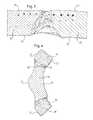
- FIG. 3is a micrograph taken on a section through the line III-III shown in FIG. 2 ;
- FIG. 4is a micrograph taken on a section through the line IV-IV shown in FIG. 2 ;
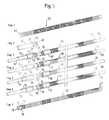
- FIG. 5shows schematically a stepwise manufacturing process.
- the material of the stent tube and its markerslies all in a circular cross-section with a wall thickness as small as possible, so as to be consistent with the objective of maintaining a bodily lumen as open as possible.
- the stent cylindercan be formed from seamless tubular starting material, or from flat material rolled into a tube (which thus exhibits some sort of seam).
- FIG. 1shows an expandable strut pattern in a form which is particularly preferred for the present Applicant, nevertheless any other strut pattern will have points in it which define an end to the cylinder of the stent, and therefore will have points at the ends of the stent cylinder where markers can be attached.
- each of the four markershas a circumferential length just less than the circumferential length of three cycles of the zigzag pattern which defines the end ring of the stent cylinder so that, when the stent cylinder is compressed, with all the struts of the zigzag ring laying close to each other, the adjacent radiopaque markers will also lie closely adjacent each other in the circumferential direction.
- the end ring 12 of the stent cylinder 10is constituted by a succession of struts 14 which zigzag their way around the full circumference of the ring 12 .
- a marker carrier portion 18is located at every third end vertex 16 , and fitted to each carrier portion 18 is a marker element 20 .
- the stentis made from Nitinol, nickel-titanium shape memory alloy, and each marker element is of tantalum.
- the stentcould be of stainless steel.
- the attached elementscould be of tantalum, platinum, gold or iridium, for example.
- the tantalum marker 20has a luminal surface 22 and an abluminal surface 24 , with the abluminal surface 24 being in line with the abluminal surface 26 of the stent cylinder and the luminal surface 22 of the marker being in line with the luminal surface 28 of the stent cylinder.
- FIG. 4shows that the peripheral surface 30 of the carrier portion 18 is tapered inwardly from the abluminal surface 26 to the luminal surface 28 of the stent cylinder.
- the marker 20has a co-operating complementary tapered mating surface 32 , therefore also defining part of a cone with its vertex lying radially inside the stent cylinder. It will be appreciated that achievement of the form fit-shown in FIG.
- surfaces 24 and 26face a bodily lumen wall.
- the stent cylinder 10 with its end ring 12 and its carrier portions 18are serving to hold back the bodily lumen wall tissue from radially inward encroachment (rightwards in FIG. 4 ).
- the tissuepresses radially inward also on the marker 20 , tending to dislodge the form-fit.
- melting and flow of Nitinol around the tantalum spoonachieves re-entrant locking surfaces, as can be seen on the photomicrograph, which effectively resist such dislodging.
- the present inventionaims to assist the attachment of tantalum markers to Nitinol stents, for example by laser-welding, and make it even more reliable and secure.
- the melting point of tantalumis around 3000° C., and that of Nitinol around 1200° C., rendering it difficult to achieve a good bond purely by welding.
- the tapered close fit between the two metals, and the flow of Nitinol around the tantalum during weldingachieves a secure mechanical interlock between the stent and the marker 20 .
- FIG. 1how the four markers 20 at each end of the stent cylinder form a virtually unbroken ring of material having a diameter exactly the same as that of the stent cylinder 10 in the delivery disposition of FIG. 1 .
- FIG. 5shows the four adjacent markers 56 are all cut from a single tube of tantalum material having the same radius as the stent cylinder 10 , a laser having been used to cut around the periphery of each marker, including the rebated portion in the centre of the marker which receives the marker portion 18 of the stent.
- the only place where the thus cut marker element 56 remains attached to the carrier tubeis at the central tip 40 ( FIG. 1 ) of the arcuate surface 42 which defines the peripheral end surface of the marker 20 remote from the stent cylinder 10 .
- a support cylinder 54which includes the four markers 20 , 56 attached at their tips 40 is offered up to the stent cylinder 10 , the two cylinders being co-linear and coaxial. There is then a snap fit of the marker portions 18 of the stent 10 into the receiving recess of each marker 20 . Once the marker portions 18 are secure within the recesses of the respective markers 20 , a laser can be deployed to produce a laser weld between the marker portion 18 and the marker 20 . During welding; the Nitinol adjacent the tantalum marker melts locally and to a limited extent flows around the tantalum, thereby effectively form-locking the marker to the stent.
- a lasercan then be brought into play, to part at marker tip 40 each individual marker 20 from the carrier tube 54 which has supported it up to that point. With this parting away of the markers 20 from their carrier tube, the stent can then be separated from the carrier tube, with the markers 20 securely welded to the stent 10 .
- the markers 20have the general form of a spoon. That is to say, the markers have two major dimensions and one minor dimension, namely, the thickness in the radial direction of the stent.
- the two major surfaceshave a length direction in the length direction of the stent and are more or less flat in that direction.
- the markersare curved so that they exhibit a luminal surface which is concave and an abluminal surface which is convex. This curvature is also exhibited in the transverse direction of a cutlery spoon.
- each marker 20has a near end surface in which is something akin to the shaft of a cutlery spoon, namely, the marker portion 18 of the stent. Opposite this end surface is another end surface, relatively remote from the stent, which is not attached to the stent and is arcuate on its periphery. This is pronounced of the arcuate (in the sense of presenting an outwardly convex shape) peripheral end surface of a cutlery spoon, remote from the shaft of the spoon.
- FIG. 5are shown seven steps, in FIGS. 5 ( 1 ) to 5 ( 7 ), of a process for manufacturing an implant in accordance with the invention, which is a stent of Nitinol having at each of its ends a ring of tantalum spoons.
- Step 1is to cut with a laser a tube of Nitinol material in order to produce a stent precursor 50 having at each ends a ring of four marker carrier portions 52 each having a shape which has some slight resemblance to an arrowhead shape.
- the Nitinol tubehas a wall thickness of 0.24 mm and a nominal diameter of 1.6 mm.
- FIG. 5 ( 2 ), showing step 2shows a tube of tantalum 54 which has the same 1.6 mm nominal diameter and 0.24 mm wall thickness but a shorter length than the stent precursor 50 .
- At one end of the tantalum tube 54has been laser-cut a ring of four spoons 56 .
- a narrow bridge of material 58 at the tip 40 on the arcuate end surface of each spoonconnects each spoon 56 to the tube 54 , and a similar narrow bridge 60 links each spoon 56 at its widest point to the corresponding point on the next adjacent spoon 56 on each side. In this way, the spoons are all linked up in a ring and each individually still part of the tantalum tube 54 .
- step 3 of the manufacturing processincludes placing a core 62 inside the tantalum tube 54 , and a surrounding sleeve 64 radially outside the tube 54 .
- the core 62 and sleeve 64do not extend as far as the ring of spoons 56 but terminate just short of that ring.
- Nitinol tube 50receives a core 66 and a surrounding sleeve 68 which again stop just short of the ring of carrier portions 52 .
- FIG. 5 ( 3 )shows each of the carrier portions 52 tilted slightly radially outwardly, to indicate that this is feasible, for offering up the carrier portions 52 into the corresponding recesses of the corresponding spoons 56 , as explained above, and as shown in FIG. 5 ( 4 ).
- FIG. 5 ( 4 )it is shown how manual manipulation of the carrier portions 52 can be used to get them into the corresponding recesses of the spoons 56 , when the cores 62 and 66 are brought closer to each other in the above-mentioned jig.
- This manual manipulation, of each individual carrier portion 52is carried out manually, under a microscope.
- FIG. 5 ( 5 )shows the carrier portions 52 duly fitted within the corresponding recesses of the spoons 56 .
- FIG. 5 ( 6 )differs from the preceding method step of FIG. 5 ( 5 ) by the presence of a welding bead 70 which connects each one of the spoons 56 with its corresponding carrier portion 52 , around the periphery of the arrowhead of the carrier portion 52 .
- This welding beadis a result of a laser-welding step which occurs between illustrated steps 5 and 6 but is not shown as such in FIG. 5 . In itself, it will be familiar to readers skilled in Nitinol stent manufacture.
- FIG. 5 ( 7 )differs from FIG. 5 ( 6 ) in that the cores 62 and 66 and the rings 64 and 68 have been removed, to leave a ring of spoons 56 duly welded to one end of the Nitinol tube stent precursor 50 .
- the bridges 58 and 60are cut through, so as to release each spoon from the tantalum tube 54 and the spoons adjacent to it.
- this precursor tubecan be subjected to the normal successor manufacturing steps, including the step of expanding the stent precursor to a desired larger diameter and then annealing it at that diameter in order to “set” a stent shape in the austenitic phase of the Nitinol material, which is the shape that it is desired the stent should revert to, in the body, upon deployment from a stent delivery system.
- a set shapemight include a central cylindrical portion of the stent, and flared portions at each end, with the ring of carrier portions 52 and spoons 56 themselves forming part of the flared portion of the end of the stent.
- tantalumhas a melting point so much higher than that of Nitinol, there is no likelihood that the Nitinol annealing step will in any way adversely affect the spoons and welding beads at each end of the stent cylinder.
Landscapes
- Health & Medical Sciences (AREA)
- Engineering & Computer Science (AREA)
- Biomedical Technology (AREA)
- General Health & Medical Sciences (AREA)
- Veterinary Medicine (AREA)
- Public Health (AREA)
- Heart & Thoracic Surgery (AREA)
- Vascular Medicine (AREA)
- Life Sciences & Earth Sciences (AREA)
- Animal Behavior & Ethology (AREA)
- Optics & Photonics (AREA)
- Physics & Mathematics (AREA)
- Cardiology (AREA)
- Transplantation (AREA)
- Oral & Maxillofacial Surgery (AREA)
- Surgery (AREA)
- Epidemiology (AREA)
- Chemical & Material Sciences (AREA)
- Inorganic Chemistry (AREA)
- Media Introduction/Drainage Providing Device (AREA)
- Prostheses (AREA)
- Materials For Medical Uses (AREA)
- Micromachines (AREA)
Abstract
Description
This application is a continuation of U.S. patent application Ser. No. 13/279,189, now U.S. Pat. No. 8,900,290, filed Oct. 21, 2011, which is a continuation of U.S. patent application Ser. No. 10/362,040, now U.S. Pat. No. 8,043,364, filed Feb. 18, 2003, which is a U.S. national stage application under 35 U.S.C. §371 of International Application No. PCT/EP01/09467, filed Aug. 16, 2001, claiming priority to United Kingdom Patent Application No. 0020491.7, filed Aug. 17, 2000, each of which is incorporated by reference in its entirety into this application.
This invention relates to an implant, such as a stent formed from a stent material, to which is attached at least one element, such as a marker, made from a different material, such as a material having a radiopacity greater than that of the implant material. The invention also relates to a method of making such an implant.
Although the present invention has particular usefulness for attaching radiopaque markers to stents, it also has application to implants (filters, for example) other than stents, and to elements other than markers. Such elements could function as, for example, drug delivery vehicles, trauma inhibitors, or connectors to link the implant to another implant or to an implant extraction tool.
WO-A-95/03010 discloses a stent in the form of a metal tube having a long axis, a luminal surface and an abluminal surface, and a tube wall thickness, the tube carrying within the wall thickness a radiopaque marker made of a metal more radiopaque than the metal which forms the tube.
The stent of WO 95/03010 is created from a flat sheet of stainless steel material, by photochemical etching away of selected areas of the metal sheet, to leave behind an open lattice-work pattern, which is then rolled up into a tubular shape. A small round opening is provided at each end of the lattice area. Into each of these openings (called “eyelets”) can be pressed a radiopaque marker of material such as gold, platinum, tungsten or iridium. The markers are positioned in the eyelets by crimping.
EP-A-800 800 also addresses the problem of poor radiopacity of stents, but advocates a different solution. In a nickel titanium shape memory alloy stent, it is proposed to provide, at one end at least of the cylinder which defines the stent, at least one detection element which has the shape of a tongue extending substantially in the longitudinal direction of the stent, this detection element having a width, in the circumferential direction of the stent cylinder, which is greater than the characteristic width, in the circumferential direction of the stent, of each of the struts which make up the lattice work pattern of the stent. It is the greater circumferential width of the tongue which renders it more radiopaque than the thinner struts of the lattice of the stent.
EP-A-847733 Biotronik discloses a stent which is an apertured cylinder of titanium, to each end of which is welded a meander-form ring of tantalum. The radiopacity of tantalum being much greater than that of titanium, this construction allows the locations of the ends of the stent cylinder to be determined radioscopically.
WO-A-00/64375 ACS was published Nov. 2, 2000, that is, after the present priority date. It discloses a stent made from wire or tube but with end rings of a material more radiopaque that its lengthwise centre section. Materials suggested for the centre section comprise Ni—Ti shape memory alloy (Nitinol) and stainless steel. Materials suggested for the end rings comprise tantalum, platinum, gold and platinum-iridium. To attach the end rings to the centre section, it is suggested to use, inter alia, laser welding.
EP-A-709 068 Medinol discloses providing stent ends with “protrusions having enough metal therein to make them X-ray visible”. Gold and tantalum are mentioned as materials which are more visible under X-ray illumination than the stainless steel metal of the stent.
The disclosure of U.S. Pat. No. 6,022,374 is similar to that of WO-A-95/03010 mentioned above, in that it discloses an insert of radiopaque material within an eyelet formed in the stent. Mentioned as radiopaque materials are gold, platinum and alloys thereof.
DE-U-29904817 discloses a stent with axially extending projections at one end, at least. These projections can exhibit a thickening at their outer cantilevered ends. This concept can be compared with the disclosure of EP-A-800800, mentioned above.
U.S. Pat. No. 5,741,327 Frantzen discloses a stent with radiopaque markers attached to the ends of the body of the stent. In one embodiment, a circumferentially continuous serpentine marker element is attached to each end of the stent. This marker element can be of gold, silver, platinum or an alloy thereof. It is disclosed that the body of the stent can be from a nickel-titanium alloy. The circumferential marker is radially expansible along with the body of the stent. A circumferential marker is attached to an end of the stent body using one of a number of techniques including brazing, mechanical fastening, weaving or epoxy adhesive. One specific system of attachment disclosed involves the use of “receivers” that extend from the ends of the stent body. These receivers are configured to receive “tabs” provided on the marker ring. Each tab has a neck and a knob at the end of the neck and the knob is received into a co-operating rounded space of the receiver of the stent body. A laser is used to achieve local melting so that the receiver and tab are fused together.
The disclosures of WO 97/33534 is similar to that of WO 95/03010, in that it includes radiopaque rivets set in a stent of less radiopaque material.
It is one object of the present invention to provide an implant, such as a stent, with an element of different material, securely fixed to the implant as such.
It is a more particular object of the present invention to provide a nickel-titanium shape memory alloy stent with a radiopaque marker which is compatible with the alloy of the stent; and biologically acceptable, and which is more effective and reliable than previous proposals.
According to one aspect of the present invention there is provided a stent recited inclaim 1 below. In a second aspect, there is provided an implant and, in a third aspect, a method of attaching elements to an implant is provided.
With a ring of elements in the form of spoons, attached at one end of a tubular implant such as a stent, a more or less complete ring of attached material is presented in the radially compact delivery disposition of the stent, yielding potentially enhanced radiopacity. Even in the expanded disposition of the stent, a relatively small number of wide area spoons, say four, delivers relatively good radiopacity. However, the radiopacity in the compact disposition is particularly high, so that the present invention opens up the possibility to eliminate the previously indispensable radiopaque marker ring on the stent delivery system which reveals the location of an end of the stent. This in turn opens up the way to make delivery systems which are simpler in construction than the systems used up to now.
If interfitting shapes of the stent ends and attached elements are cut by a laser with its line of action always radial to the stent cylinder, then a tapered or beveled form fit between the stent and each attached element is achieved, enhancing the security of attachment and the precision of placement of each element attached to the stent.
This tapered form fit is particularly helpful when it is such that disengagement of the form-fit occurs by a radially-outward movement of the element relative to the stent cylinder. This is because, when the stent expands into its installed configuration, there is radially-inward pressure on the attached element from the surrounding bodily tissue, which resists its disengagement from the stent. This resistance complements and reinforces whatever other system is employed to fix the element to the stent.
Systems to fix an element to an implant can include welding, brazing, soldering, glueing, friction welding or variations of mechanical interlocks and press-fit configurations.
When creating stent lattices from sheet material, tubular sheet starting material is often considered advantageous. However, flat sheet material also is advantageous in some systems, such as those in which the stent element is rolled up like a carpet. When laser-cutting the lattice, the above-mentioned tapered form fit can be readily engineered when cutting the sheet in planar form.
In a particularly advantageous embodiment, a stent is formed from sheet material in the form of a tube, and is provided at each end with a plurality of marker carrier portions, to each of which is mounted a radiopaque marker of radiopaque material, in the form of a spoon. Each of the carriers has a luminal surface, an abluminal surface, and a peripheral surface through the thickness of the stent tube. It is this peripheral surface which provides one of two complementary mating surfaces for making the stent/marker attachment. The complementary marker itself has two major surfaces, one of which is luminal and the other is abluminal, and a peripheral surface around the major surfaces. However, within the area of the major surfaces is a cavity portion. The periphery of this cavity defines a female element for engagement with a male portion of the stent tube marker carrier portion, the male and female peripheral surfaces providing complementary tapering form-fit surfaces.
Preferably each such ring of markers has four marker spoons in it. Increasing beyond four reduces the size of each marker. In the expanded configuration of the stent, visibility of the stent increases with the physical area of each separate marker, so large markers are preferred because they make the expanded stent more visible.
It is preferred that the markers together make a more or less continuous ring around the stent in its small diameter configuration prior to its deployment by expansion.
According to the second aspect of the present invention there is provided a method for making from sheet material a tubular implant, such as a stent, which expands, during its deployment, from a smaller radius delivery disposition to a larger radius deployed disposition, the method comprising the steps of:
1. providing at least one terminal element on one end of a support of sheet material arranged as a cylinder with its radius being that of the said delivery disposition;
2. presenting the tubular implant in its smaller radius, end-to-end with the support, such that the terminal element abuts the implant;
3. fixing the terminal element to the implant; and
4. parting the terminal element from the support.
One of the problems involved in fixing radiopaque markers to stents is the difficulty of aligning the markers with the stent in order to fix the markers to the stent in exactly the right orientation and position relative to the stent as such. This second aspect of the invention ameliorates this problem by presenting markers as terminal elements on one end of a cylindrical support of sheet material which has the same radius as the stent in its unexpanded disposition. This is because it is relatively easy to arrange in co-linear fashion the cylinder of the stent and the cylinder of the support and, with both of these items having the same radius, the cylindrical end surface of the support would be in abutment with the cylindrical end surface of the stent. Now, if the cylindrical end surface of the support exhibits a plurality of terminal elements which are destined to become elements attached to the stent, the process of fixing these markers to the stent can be effected by welding the elements to the end of the stent, while they are in end-to-end abutment with the stent end. Then, when this welding step has been completed, it should be a simple further step to part the marker elements from the support cylinder, for example, by laser-cutting through the thickness of the sheet material which forms the support.
It will be appreciated that the terminal elements will have the curvature of the support cylinder, which curvature will correspond to the curvature of the stent in its delivery disposition. Thus, when the stent expands to its deployed disposition, and the curvature of the terminal elements remains unchanged, these elements will have a radius of curvature somewhat smaller than the radius of the expanded stent cylinder. However, this discrepancy in curvature will not be significant because the terminal elements will be, to a greater or lesser extent, embedded in the bodily tissue forming the wall of the lumen in which the stent is deployed. Indeed, the elements might have no curvature at all. This would be the case if, for example, the main stent manufacturing steps are performed on flat sheet material, while it is planar, with the stent lattice then being rolled up for installation into a delivery system. The rolling up step would impart a curvature to the stent, but not necessarily to the attached elements.
The invention is particularly well adapted to the technical field of shape memory alloy stents, specifically those made of Nitinol, and the attachment to them of terminal marker elements of tantalum.
In order to make Nitinol stents more visible to radiation, by the provision of tantalum markers, one would wish to import a greater mass of tantalum, but without any increase in the wall thickness of the stent at the locations of the markers. The ideal stent has minimal wall thickness, not only for keeping the stented bodily lumen as open to fluid as possible, but also to keep the stent delivery system with as small a cross-sectional profile as possible. The present invention furthers this objective, in the following way.
The cylinder of sheet material which provides the terminal elements and support tube is amenable to laser-cutting of the terminal elements out of the material of the tube. Accordingly, virtually all of the material forming the circumference of the tube is available for contribution to the making of the terminal elements. The terminal elements can take up the entire circumference of the support tube, except for the thickness of the laser cuts between adjacent terminal elements around the circumference. Accordingly, for the stent in its small radius delivery disposition, there could be virtually an entire circumference of radiopaque tantalum marker material provided at each end of the stent, with the only breaks in the continuous ring around the circumference being the laser cuts between adjacent marker elements.
In one specific embodiment, there is laser-cut from the support tube a pattern of four terminal marker elements, each extending around one quarter of the circumference of the support tube. Each of these marker elements takes up virtually ninety degrees of the circumference of the stent in its delivery disposition.
The exact shape of the outline of each terminal element, and the exact shape of the abutment surface on it which contacts the corresponding abutment surface of the end of the implant, is a matter of design freedom and choice. At the moment, for implants which are stents, and attached elements which are radiopaque markers, it is contemplated to provide each element with more or less straight sides to face the adjacent marker elements around the circumference of the stent, but with an arcuate end surface and a female rebated internal abutment surface to receive a corresponding arrowhead shape male marker carrier portion on the end ring of the stent. Such a pattern of shape features is described in more detail below by reference to the accompanying drawings.
With a male/female interfit of the marker element and stent end ring carrier portions, with rebated surfaces, and with the respective peripheral mating surfaces extending along radial lines to the stent cylinder, a snap fit interengagement of the stent cylinder and support cylinder can be arranged, further helping to accomplish the objective of precise position and orientation of the marker elements relative to the stent cylinder.
In any event, a convenient way to fix permanently and reliably the tantalum marker elements to a Nitinol stent cylinder is by laser-welding. When laser-cutting the lattice of a stent from a cylinder of sheet material, the line of action of the laser is invariably on a radius of the tubular workpiece. If the co-operating surfaces of the stent, and of its spoons, end elements or markers, are both cut with a laser on a radial line of action, then there will tend to be a self-centering and self-aligning effect when the support tube is offered up, end-to-end to the stent in its small radius of compressed configuration. This effect enhances the value of the method of the present invention in building stent assemblies to precise tolerances and with its end elements securely attached.
For a better understanding of the present invention, and to show more clearly how the same may be carried into effect, reference will now be made, by way of example, to the accompanying drawings.
Skilled readers will appreciate that the material of the stent tube and its markers lies all in a circular cross-section with a wall thickness as small as possible, so as to be consistent with the objective of maintaining a bodily lumen as open as possible. The stent cylinder can be formed from seamless tubular starting material, or from flat material rolled into a tube (which thus exhibits some sort of seam).
Skilled readers will also be well aware that there have been a very large number of proposals for strut patterns in the tubular configurations of stents. WhereasFIG. 1 shows an expandable strut pattern in a form which is particularly preferred for the present Applicant, nevertheless any other strut pattern will have points in it which define an end to the cylinder of the stent, and therefore will have points at the ends of the stent cylinder where markers can be attached.
Readers will also appreciate that self-expanding stents are delivered to stenting locations in a radially compressed form, so that the aggregate length, in the circumferential direction, of all of the markers in any particular ring around the axis of the stent tube cannot exceed the circumference of the stent tube in its compressed delivery configuration. In the embodiment shown inFIG. 1 , each of the four markers has a circumferential length just less than the circumferential length of three cycles of the zigzag pattern which defines the end ring of the stent cylinder so that, when the stent cylinder is compressed, with all the struts of the zigzag ring laying close to each other, the adjacent radiopaque markers will also lie closely adjacent each other in the circumferential direction.
As can be seen inFIG. 1 , theend ring 12 of thestent cylinder 10 is constituted by a succession ofstruts 14 which zigzag their way around the full circumference of thering 12. There is avertex 16 where each two successive struts intersect, with the end of the stent cylinder being defined by the succession ofvertices 16. Amarker carrier portion 18 is located at everythird end vertex 16, and fitted to eachcarrier portion 18 is amarker element 20. In the illustrated embodiment, the stent is made from Nitinol, nickel-titanium shape memory alloy, and each marker element is of tantalum. In other embodiments, the stent could be of stainless steel. The attached elements could be of tantalum, platinum, gold or iridium, for example.
Referring now toFIGS. 3 and 4 together, thetantalum marker 20 has aluminal surface 22 and anabluminal surface 24, with theabluminal surface 24 being in line with theabluminal surface 26 of the stent cylinder and theluminal surface 22 of the marker being in line with theluminal surface 28 of the stent cylinder.FIG. 4 shows that theperipheral surface 30 of thecarrier portion 18 is tapered inwardly from theabluminal surface 26 to theluminal surface 28 of the stent cylinder. Themarker 20 has a co-operating complementary taperedmating surface 32, therefore also defining part of a cone with its vertex lying radially inside the stent cylinder. It will be appreciated that achievement of the form fit-shown inFIG. 4 is by advancing thecarrier portion 18 radially inwardly into the cavity defined bysurface 32 of themarker 20 until there is a tight fit between the two complementarytapered surfaces
InFIG. 4 surfaces stent cylinder 10 with itsend ring 12 and itscarrier portions 18 are serving to hold back the bodily lumen wall tissue from radially inward encroachment (rightwards inFIG. 4 ). The tissue presses radially inward also on themarker 20, tending to dislodge the form-fit. However, in laser-welding thetantalum spoon 20 to theNitinol carrier portion 18, melting and flow of Nitinol around the tantalum spoon achieves re-entrant locking surfaces, as can be seen on the photomicrograph, which effectively resist such dislodging.
The present invention aims to assist the attachment of tantalum markers to Nitinol stents, for example by laser-welding, and make it even more reliable and secure. The melting point of tantalum is around 3000° C., and that of Nitinol around 1200° C., rendering it difficult to achieve a good bond purely by welding. However, the tapered close fit between the two metals, and the flow of Nitinol around the tantalum during welding, achieves a secure mechanical interlock between the stent and themarker 20.
It is conventional to form the lattice patterns of Nitinol stents by laser-cutting. The line of action of a laser for cutting the tapered mating surfaces30 of thecarrier portion 18 in the stent are achieved by aligning the laser in the normal radial direction of intersecting the long axis of the stent tube
As to the number of markers in one circumference of the stent, optimum radiopacity is accomplished when the markers at each end of the stent make up a virtually unbroken solid ring of marker material around the full circumference. In the case shown there is a marker on every third end vertex of the stent, with 4 markers at each end of the stent, and 12 zigzag vertices around the circumference of the stent. This, however, is not to exclude the possibility of fewer markers at each end of the stent, including the extreme case, seen in wo 95/03010, mentioned at the beginning of this specification, that there is only one marker at each end of the stent cylinder.
Turning now to the second aspect of the invention, and to the assembly of themarkers 20 onto thestent 10, one can see fromFIG. 1 how the fourmarkers 20 at each end of the stent cylinder form a virtually unbroken ring of material having a diameter exactly the same as that of thestent cylinder 10 in the delivery disposition ofFIG. 1 .
Asupport cylinder 54 which includes the fourmarkers tips 40 is offered up to thestent cylinder 10, the two cylinders being co-linear and coaxial. There is then a snap fit of themarker portions 18 of thestent 10 into the receiving recess of eachmarker 20. Once themarker portions 18 are secure within the recesses of therespective markers 20, a laser can be deployed to produce a laser weld between themarker portion 18 and themarker 20. During welding; the Nitinol adjacent the tantalum marker melts locally and to a limited extent flows around the tantalum, thereby effectively form-locking the marker to the stent. With this laser welding accomplished, a laser can then be brought into play, to part atmarker tip 40 eachindividual marker 20 from thecarrier tube 54 which has supported it up to that point. With this parting away of themarkers 20 from their carrier tube, the stent can then be separated from the carrier tube, with themarkers 20 securely welded to thestent 10.
Readers will immediately appreciate from the above description, taken in conjunction with the drawings, that themarkers 20 have the general form of a spoon. That is to say, the markers have two major dimensions and one minor dimension, namely, the thickness in the radial direction of the stent. The two major surfaces have a length direction in the length direction of the stent and are more or less flat in that direction. However, in the transverse direction, circumferential with respect to the stent cylinder, the markers are curved so that they exhibit a luminal surface which is concave and an abluminal surface which is convex. This curvature is also exhibited in the transverse direction of a cutlery spoon.
Further, eachmarker 20 has a near end surface in which is something akin to the shaft of a cutlery spoon, namely, themarker portion 18 of the stent. Opposite this end surface is another end surface, relatively remote from the stent, which is not attached to the stent and is arcuate on its periphery. This is reminiscent of the arcuate (in the sense of presenting an outwardly convex shape) peripheral end surface of a cutlery spoon, remote from the shaft of the spoon.
InFIG. 5 are shown seven steps, inFIGS. 5 (1) to5(7), of a process for manufacturing an implant in accordance with the invention, which is a stent of Nitinol having at each of its ends a ring of tantalum spoons.
InFIG. 5 (3),step 3 of the manufacturing process includes placing acore 62 inside thetantalum tube 54, and a surroundingsleeve 64 radially outside thetube 54. Thecore 62 andsleeve 64 do not extend as far as the ring ofspoons 56 but terminate just short of that ring. Likewise,Nitinol tube 50 receives acore 66 and a surroundingsleeve 68 which again stop just short of the ring ofcarrier portions 52. In a jig, the two spacedcores carrier portions 52 and ring ofspoons 56 are themselves co-axial and co-linear.FIG. 5 (3) shows each of thecarrier portions 52 tilted slightly radially outwardly, to indicate that this is feasible, for offering up thecarrier portions 52 into the corresponding recesses of the correspondingspoons 56, as explained above, and as shown inFIG. 5 (4).
InFIG. 5 (4), it is shown how manual manipulation of thecarrier portions 52 can be used to get them into the corresponding recesses of thespoons 56, when thecores individual carrier portion 52 in turn, is carried out manually, under a microscope.
Clearly, if it desired to place a ring of spoons at the other end of thestent tube 50 then the process can be repeated at this other end. Indeed, inFIG. 5 , a ring ofcarrier portions 72 is shown at the other end of thestent tube 50.
Once the spoons have been placed as desired on theprecursor tube 50 of the stent, then this precursor tube can be subjected to the normal successor manufacturing steps, including the step of expanding the stent precursor to a desired larger diameter and then annealing it at that diameter in order to “set” a stent shape in the austenitic phase of the Nitinol material, which is the shape that it is desired the stent should revert to, in the body, upon deployment from a stent delivery system. Such a set shape might include a central cylindrical portion of the stent, and flared portions at each end, with the ring ofcarrier portions 52 andspoons 56 themselves forming part of the flared portion of the end of the stent. As tantalum has a melting point so much higher than that of Nitinol, there is no likelihood that the Nitinol annealing step will in any way adversely affect the spoons and welding beads at each end of the stent cylinder.
The scope of protection of the claims which follow is not to be limited to the embodiments described in detail above. Readers will appreciate that the detailed description is to assist in realising embodiments within the scope of the claim rather than to set a limit on the scope of protection.
Claims (12)
1. A stent, having:
an axial end; and
a ring of spoons connected to the axial end through a plurality of complementary male-female form-fitting portions, the ring of spoons comprising:
parallel straight side edges; and
a material different from a material composing the stent, wherein:
the stent expands from a delivery configuration to a deployed configuration and the diameter of the deployed configuration is greater than the diameter of the delivery configuration; and
each of the side edges lies within a first distance from a facing side edge of an adjacent spoon in the delivery configuration, and each of the side edges lies within a second distance, greater than the first distance, from the facing side edge of an adjacent spoon in the deployed configuration.
2. The stent according toclaim 1 , wherein the material of the ring of spoons is tantalum.
3. The stent according toclaim 2 , wherein the material composing the stent is either stainless steel or a nickel-titanium shape memory alloy.
4. The stent according toclaim 1 , wherein the ring of spoons is attached to the stent via laser-welding.
5. The stent according toclaim 1 , wherein each spoon of the ring of spoons has an axial length between a first end and a second end, the first end having the form-fitting portion and the second end having a convex shape.
6. The stent according toclaim 1 , wherein each spoon of the ring of spoons has a luminal major surface and an abluminal major surface, each of the major surfaces being arcuate and within a cylindrical envelope which corresponds to the delivery configuration.
7. The stent according toclaim 6 , wherein each spoon of the ring of spoons extends around about one quarter of a circumference of the stent.
8. The stent according toclaim 1 , wherein the ring of spoons are radiopaque markers.
9. The stent according toclaim 1 , wherein the complementary male-female formfitting portions have complementary tapered mating surfaces lying in a plane that intersects a longitudinal axis of the stent.
10. The stent according toclaim 9 , wherein the tapered mating surfaces constitute the female portion of the male-female form-fitting portions.
11. The stent according toclaim 10 , wherein each of the tapered mating surfaces has a barbed, arrowhead shape.
12. The stent according toclaim 11 , wherein the ring of spoons is attached to the stent via laser-welding.
Priority Applications (2)
| Application Number | Priority Date | Filing Date | Title |
|---|---|---|---|
| US14/495,820US9480587B2 (en) | 2000-08-17 | 2014-09-24 | Implant with attached element and method of making such an implant |
| US15/337,448US10213327B2 (en) | 2000-08-17 | 2016-10-28 | Implant with attached element and method of making such an implant |
Applications Claiming Priority (6)
| Application Number | Priority Date | Filing Date | Title |
|---|---|---|---|
| GB0020491.7 | 2000-08-18 | ||
| GBGB0020491.7AGB0020491D0 (en) | 2000-08-18 | 2000-08-18 | Stent with attached element and method of making such a stent |
| PCT/EP2001/009467WO2002015820A2 (en) | 2000-08-18 | 2001-08-16 | Implant with attached element and method of making such an implant |
| US10/362,040US8043364B2 (en) | 2000-08-18 | 2001-08-16 | Implant with attached element and method of making such an implant |
| US13/279,189US8900290B2 (en) | 2000-08-17 | 2011-10-21 | Implant with attached element and method of making such an implant |
| US14/495,820US9480587B2 (en) | 2000-08-17 | 2014-09-24 | Implant with attached element and method of making such an implant |
Related Parent Applications (1)
| Application Number | Title | Priority Date | Filing Date |
|---|---|---|---|
| US13/279,189ContinuationUS8900290B2 (en) | 2000-08-17 | 2011-10-21 | Implant with attached element and method of making such an implant |
Related Child Applications (1)
| Application Number | Title | Priority Date | Filing Date |
|---|---|---|---|
| US15/337,448DivisionUS10213327B2 (en) | 2000-08-17 | 2016-10-28 | Implant with attached element and method of making such an implant |
Publications (2)
| Publication Number | Publication Date |
|---|---|
| US20150073532A1 US20150073532A1 (en) | 2015-03-12 |
| US9480587B2true US9480587B2 (en) | 2016-11-01 |
Family
ID=9897949
Family Applications (5)
| Application Number | Title | Priority Date | Filing Date |
|---|---|---|---|
| US13/402,787Expired - Fee RelatedUSRE44463E1 (en) | 2000-08-18 | 2001-08-16 | Implant with attached element and method of making such an implant |
| US10/362,040CeasedUS8043364B2 (en) | 2000-08-17 | 2001-08-16 | Implant with attached element and method of making such an implant |
| US13/279,189Expired - Fee RelatedUS8900290B2 (en) | 2000-08-17 | 2011-10-21 | Implant with attached element and method of making such an implant |
| US14/495,820Expired - Fee RelatedUS9480587B2 (en) | 2000-08-17 | 2014-09-24 | Implant with attached element and method of making such an implant |
| US15/337,448Expired - LifetimeUS10213327B2 (en) | 2000-08-17 | 2016-10-28 | Implant with attached element and method of making such an implant |
Family Applications Before (3)
| Application Number | Title | Priority Date | Filing Date |
|---|---|---|---|
| US13/402,787Expired - Fee RelatedUSRE44463E1 (en) | 2000-08-18 | 2001-08-16 | Implant with attached element and method of making such an implant |
| US10/362,040CeasedUS8043364B2 (en) | 2000-08-17 | 2001-08-16 | Implant with attached element and method of making such an implant |
| US13/279,189Expired - Fee RelatedUS8900290B2 (en) | 2000-08-17 | 2011-10-21 | Implant with attached element and method of making such an implant |
Family Applications After (1)
| Application Number | Title | Priority Date | Filing Date |
|---|---|---|---|
| US15/337,448Expired - LifetimeUS10213327B2 (en) | 2000-08-17 | 2016-10-28 | Implant with attached element and method of making such an implant |
Country Status (11)
| Country | Link |
|---|---|
| US (5) | USRE44463E1 (en) |
| EP (2) | EP1634546B1 (en) |
| JP (1) | JP4933018B2 (en) |
| AT (2) | ATE318554T1 (en) |
| AU (1) | AU2001279819A1 (en) |
| CA (1) | CA2419830C (en) |
| DE (2) | DE60131305T2 (en) |
| EA (1) | EA004285B1 (en) |
| GB (1) | GB0020491D0 (en) |
| MX (1) | MXPA02012823A (en) |
| WO (1) | WO2002015820A2 (en) |
Families Citing this family (104)
| Publication number | Priority date | Publication date | Assignee | Title |
|---|---|---|---|---|
| US6503271B2 (en) | 1998-01-09 | 2003-01-07 | Cordis Corporation | Intravascular device with improved radiopacity |
| GB0003387D0 (en) | 2000-02-14 | 2000-04-05 | Angiomed Ag | Stent matrix |
| US20030114918A1 (en)* | 2000-04-28 | 2003-06-19 | Garrison Michi E. | Stent graft assembly and method |
| GB0020491D0 (en) | 2000-08-18 | 2000-10-11 | Angiomed Ag | Stent with attached element and method of making such a stent |
| US6863685B2 (en) | 2001-03-29 | 2005-03-08 | Cordis Corporation | Radiopacity intraluminal medical device |
| WO2002067782A2 (en)† | 2001-02-26 | 2002-09-06 | Ev3 Peripheral, Inc. | Implant delivery system with interlock |
| US8197535B2 (en) | 2001-06-19 | 2012-06-12 | Cordis Corporation | Low profile improved radiopacity intraluminal medical device |
| ATE415895T1 (en) | 2001-07-06 | 2008-12-15 | Angiomed Ag | DELIVERY SYSTEM HAVING A SELF-EXPANDING STENT SLIDE ASSEMBLY AND A QUICK-CHANGE CONFIGURATION |
| GB0123633D0 (en) | 2001-10-02 | 2001-11-21 | Angiomed Ag | Stent delivery system |
| GB0206061D0 (en) | 2002-03-14 | 2002-04-24 | Angiomed Ag | Metal structure compatible with MRI imaging, and method of manufacturing such a structure |
| AU2003239369A1 (en) | 2002-05-06 | 2003-11-17 | Abbott Laboratories | Endoprosthesis for controlled contraction and expansion |
| US7128756B2 (en) | 2002-05-08 | 2006-10-31 | Abbott Laboratories | Endoprosthesis having foot extensions |
| US6814746B2 (en) | 2002-11-01 | 2004-11-09 | Ev3 Peripheral, Inc. | Implant delivery system with marker interlock |
| EP1589903B1 (en) | 2003-01-15 | 2016-01-13 | Angiomed GmbH & Co. Medizintechnik KG | Trans-luminal surgical device |
| GB0309616D0 (en) | 2003-04-28 | 2003-06-04 | Angiomed Gmbh & Co | Loading and delivery of self-expanding stents |
| US7625398B2 (en) | 2003-05-06 | 2009-12-01 | Abbott Laboratories | Endoprosthesis having foot extensions |
| US7625401B2 (en) | 2003-05-06 | 2009-12-01 | Abbott Laboratories | Endoprosthesis having foot extensions |
| US20040236414A1 (en)* | 2003-05-23 | 2004-11-25 | Brar Balbir S. | Devices and methods for treatment of stenotic regions |
| US7226473B2 (en)* | 2003-05-23 | 2007-06-05 | Brar Balbir S | Treatment of stenotic regions |
| DE10325678A1 (en)* | 2003-06-02 | 2004-12-23 | Biotronik Meß- und Therapiegeräte GmbH & Co. Ingenieurbüro Berlin | Connection system for connecting a stent to a radio-opaque marker and method for establishing a connection between a stent and two or more radio-opaque markers |
| US8021418B2 (en)* | 2003-06-19 | 2011-09-20 | Boston Scientific Scimed, Inc. | Sandwiched radiopaque marker on covered stent |
| US20050060025A1 (en)* | 2003-09-12 | 2005-03-17 | Mackiewicz David A. | Radiopaque markers for medical devices |
| GB0322511D0 (en) | 2003-09-25 | 2003-10-29 | Angiomed Ag | Lining for bodily lumen |
| JP4546481B2 (en)* | 2003-09-30 | 2010-09-15 | アルヴィオラス,インコーポレイテッド | Removable stent |
| GB0400571D0 (en) | 2004-01-12 | 2004-02-11 | Angiomed Gmbh & Co | Implant |
| FR2867059B1 (en)* | 2004-03-03 | 2006-05-26 | Braun Medical | ENDOPROTHESIS WITH MARKERS FOR CONDUCTING A LIVING BODY |
| EP2336747B1 (en) | 2004-05-06 | 2017-08-30 | Nippon Telegraph And Telephone Corporation | Component concentration measuring device |
| US8313524B2 (en) | 2004-08-31 | 2012-11-20 | C. R. Bard, Inc. | Self-sealing PTFE graft with kink resistance |
| US9468704B2 (en) | 2004-09-07 | 2016-10-18 | Biotronik Vi Patent Ag | Implant made of a biodegradable magnesium alloy |
| US7695506B2 (en)* | 2004-09-21 | 2010-04-13 | Boston Scientific Scimed, Inc. | Atraumatic connections for multi-component stents |
| DE102004045994A1 (en)* | 2004-09-22 | 2006-03-30 | Campus Gmbh & Co. Kg | Stent for implantation in or around a hollow organ with marker elements made from a radiopaque material |
| GB0425152D0 (en)* | 2004-11-15 | 2004-12-15 | Middlesex Silver Co Ltd | Fabric structure |
| CN100348281C (en)* | 2005-01-06 | 2007-11-14 | 东南大学 | Large-radical-support-force medical stent |
| DE102005003632A1 (en) | 2005-01-20 | 2006-08-17 | Fraunhofer-Gesellschaft zur Förderung der angewandten Forschung e.V. | Catheter for the transvascular implantation of heart valve prostheses |
| DE102005019649A1 (en)* | 2005-04-26 | 2006-11-02 | Alveolus Inc. | Flexible stent for positioning in lumen of esophagus comprises tube and stabilization members defined circumferentially about tube, where each member extends inwardly in tube to define inner diameter that is less than inner diameter of tube |
| US8652193B2 (en) | 2005-05-09 | 2014-02-18 | Angiomed Gmbh & Co. Medizintechnik Kg | Implant delivery device |
| GB0512319D0 (en) | 2005-06-16 | 2005-07-27 | Angiomed Ag | Catheter device variable pusher |
| GB0512321D0 (en) | 2005-06-16 | 2005-07-27 | Angiomed Ag | Catheter device double swaging |
| GB0512320D0 (en) | 2005-06-16 | 2005-07-27 | Angiomed Ag | Catheter device FLEXX tube |
| JP2009501027A (en) | 2005-06-17 | 2009-01-15 | シー・アール・バード・インコーポレイテツド | Vascular graft with kinking resistance after tightening |
| EP2364676B1 (en) | 2005-06-30 | 2018-12-19 | Abbott Laboratories | Endoprosthesis having foot extensions |
| CA2626598A1 (en) | 2005-11-09 | 2007-05-18 | C.R. Bard Inc. | Grafts and stent grafts having a radiopaque marker |
| US20070156230A1 (en) | 2006-01-04 | 2007-07-05 | Dugan Stephen R | Stents with radiopaque markers |
| GB0609841D0 (en) | 2006-05-17 | 2006-06-28 | Angiomed Ag | Bend-capable tubular prosthesis |
| GB0609911D0 (en) | 2006-05-18 | 2006-06-28 | Angiomed Ag | Bend-capable stent prosthesis |
| US20130325107A1 (en) | 2006-05-26 | 2013-12-05 | Abbott Cardiovascular Systems Inc. | Stents With Radiopaque Markers |
| GB0613670D0 (en)* | 2006-07-10 | 2006-08-16 | Angiomed Ag | Tubular metal prosthesis and method of making it |
| DE102006038232A1 (en)* | 2006-08-07 | 2008-02-14 | Biotronik Vi Patent Ag | Endoprosthesis and method for producing such |
| GB0616729D0 (en)* | 2006-08-23 | 2006-10-04 | Angiomed Ag | Method of welding a component to a shape memory alloy workpiece |
| GB0616999D0 (en) | 2006-08-29 | 2006-10-04 | Angiomed Ag | Annular mesh |
| EP2063824B1 (en) | 2006-09-07 | 2020-10-28 | Angiomed GmbH & Co. Medizintechnik KG | Helical implant having different ends |
| US9198749B2 (en) | 2006-10-12 | 2015-12-01 | C. R. Bard, Inc. | Vascular grafts with multiple channels and methods for making |
| GB0622465D0 (en) | 2006-11-10 | 2006-12-20 | Angiomed Ag | Stent |
| GB0624419D0 (en) | 2006-12-06 | 2007-01-17 | Angiomed Ag | Stenting ring with marker |
| WO2008096512A1 (en) | 2007-02-09 | 2008-08-14 | Piolax Medical Devices, Inc. | Stent |
| GB0703379D0 (en) | 2007-02-21 | 2007-03-28 | Angiomed Ag | Stent with radiopaque marker |
| US8545548B2 (en) | 2007-03-30 | 2013-10-01 | DePuy Synthes Products, LLC | Radiopaque markers for implantable stents and methods for manufacturing the same |
| DE102007015670A1 (en) | 2007-03-31 | 2008-10-02 | Biotronik Vi Patent Ag | Stent with radially expandable body |
| GB0706499D0 (en) | 2007-04-03 | 2007-05-09 | Angiomed Ag | Bendable stent |
| US7896915B2 (en) | 2007-04-13 | 2011-03-01 | Jenavalve Technology, Inc. | Medical device for treating a heart valve insufficiency |
| US9138315B2 (en) | 2007-04-13 | 2015-09-22 | Jenavalve Technology Gmbh | Medical device for treating a heart valve insufficiency or stenosis |
| GB0717481D0 (en)* | 2007-09-07 | 2007-10-17 | Angiomed Ag | Self-expansible stent with radiopaque markers |
| BR112012021347A2 (en) | 2008-02-26 | 2019-09-24 | Jenavalve Tecnology Inc | stent for positioning and anchoring a valve prosthesis at an implantation site in a patient's heart |
| US9044318B2 (en) | 2008-02-26 | 2015-06-02 | Jenavalve Technology Gmbh | Stent for the positioning and anchoring of a valvular prosthesis |
| DE602008006079D1 (en) | 2008-09-30 | 2011-05-19 | Biotronik Vi Patent Ag | Implant made of a biodegradable magnesium alloy |
| GB0822106D0 (en) | 2008-12-03 | 2009-01-07 | Angiomed Ag | Retractable catheter |
| GB0901496D0 (en) | 2009-01-29 | 2009-03-11 | Angiomed Ag | Delivery device for delivering a stent device |
| GB0909319D0 (en) | 2009-05-29 | 2009-07-15 | Angiomed Ag | Transluminal delivery system |
| US8808353B2 (en) | 2010-01-30 | 2014-08-19 | Abbott Cardiovascular Systems Inc. | Crush recoverable polymer scaffolds having a low crossing profile |
| US8568471B2 (en) | 2010-01-30 | 2013-10-29 | Abbott Cardiovascular Systems Inc. | Crush recoverable polymer scaffolds |
| US10856978B2 (en) | 2010-05-20 | 2020-12-08 | Jenavalve Technology, Inc. | Catheter system |
| WO2011147849A1 (en) | 2010-05-25 | 2011-12-01 | Jenavalve Technology Inc. | Prosthetic heart valve and transcatheter delivered endoprosthesis comprising a prosthetic heart valve and a stent |
| US9028540B2 (en)* | 2011-03-25 | 2015-05-12 | Covidien Lp | Vascular stent with improved vessel wall apposition |
| US8726483B2 (en) | 2011-07-29 | 2014-05-20 | Abbott Cardiovascular Systems Inc. | Methods for uniform crimping and deployment of a polymer scaffold |
| JP6220386B2 (en) | 2012-05-14 | 2017-10-25 | シー・アール・バード・インコーポレーテッドC R Bard Incorporated | Uniformly expandable stent |
| US9233015B2 (en) | 2012-06-15 | 2016-01-12 | Trivascular, Inc. | Endovascular delivery system with an improved radiopaque marker scheme |
| US9254205B2 (en) | 2012-09-27 | 2016-02-09 | Covidien Lp | Vascular stent with improved vessel wall apposition |
| BR112015009302A2 (en)* | 2012-10-25 | 2017-07-04 | Arterial Remodeling Tech S A | Method of applying a radiopaque marker and apparatus |
| IN2014DE00462A (en)* | 2013-03-11 | 2015-06-12 | Depuy Synthes Products Llc | |
| USD723165S1 (en) | 2013-03-12 | 2015-02-24 | C. R. Bard, Inc. | Stent |
| US10561509B2 (en) | 2013-03-13 | 2020-02-18 | DePuy Synthes Products, Inc. | Braided stent with expansion ring and method of delivery |
| CN105491978A (en) | 2013-08-30 | 2016-04-13 | 耶拿阀门科技股份有限公司 | Radially collapsible frame for a prosthetic valve and method for manufacturing such a frame |
| US10206796B2 (en) | 2014-08-27 | 2019-02-19 | DePuy Synthes Products, Inc. | Multi-strand implant with enhanced radiopacity |
| US9999527B2 (en) | 2015-02-11 | 2018-06-19 | Abbott Cardiovascular Systems Inc. | Scaffolds having radiopaque markers |
| JP6546761B2 (en)* | 2015-03-18 | 2019-07-17 | 株式会社グッドマン | Stent |
| EP3270825B1 (en) | 2015-03-20 | 2020-04-22 | JenaValve Technology, Inc. | Heart valve prosthesis delivery system |
| US10709555B2 (en) | 2015-05-01 | 2020-07-14 | Jenavalve Technology, Inc. | Device and method with reduced pacemaker rate in heart valve replacement |
| US9700443B2 (en) | 2015-06-12 | 2017-07-11 | Abbott Cardiovascular Systems Inc. | Methods for attaching a radiopaque marker to a scaffold |
| WO2017195125A1 (en) | 2016-05-13 | 2017-11-16 | Jenavalve Technology, Inc. | Heart valve prosthesis delivery system and method for delivery of heart valve prosthesis with introducer sheath and loading system |
| US10076428B2 (en) | 2016-08-25 | 2018-09-18 | DePuy Synthes Products, Inc. | Expansion ring for a braided stent |
| US10292851B2 (en) | 2016-09-30 | 2019-05-21 | DePuy Synthes Products, Inc. | Self-expanding device delivery apparatus with dual function bump |
| EP3348239A1 (en)* | 2017-01-11 | 2018-07-18 | Biotronik AG | X-ray markers for scaffolds |
| WO2018138658A1 (en) | 2017-01-27 | 2018-08-02 | Jenavalve Technology, Inc. | Heart valve mimicry |
| US11426295B2 (en)* | 2017-07-07 | 2022-08-30 | Kaneka Corporation | Tubular medical instrument and transfer device for a tubular medical instrument |
| CN109966016B (en)* | 2017-12-27 | 2021-02-23 | 先健科技(深圳)有限公司 | Covered stent |
| CN110123406B (en)* | 2018-02-02 | 2024-05-17 | 微创神通医疗科技(上海)有限公司 | Implant delivery device |
| AU2019204522A1 (en) | 2018-07-30 | 2020-02-13 | DePuy Synthes Products, Inc. | Systems and methods of manufacturing and using an expansion ring |
| US10456280B1 (en) | 2018-08-06 | 2019-10-29 | DePuy Synthes Products, Inc. | Systems and methods of using a braided implant |
| US10278848B1 (en) | 2018-08-06 | 2019-05-07 | DePuy Synthes Products, Inc. | Stent delivery with expansion assisting delivery wire |
| CN109223265A (en)* | 2018-10-31 | 2019-01-18 | 胡冰 | A kind of opening balloon type biliary tract anti-countercurrent stent |
| US12088029B2 (en)* | 2021-07-20 | 2024-09-10 | Dell Products L.P. | Cable termination for information handling systems |
| CN114985907A (en)* | 2022-05-19 | 2022-09-02 | 深圳泰德激光技术股份有限公司 | Blood vessel stent and manufacturing method thereof |
| WO2024102411A1 (en) | 2022-11-09 | 2024-05-16 | Jenavalve Technology, Inc. | Catheter system for sequential deployment of an expandable implant |
| WO2024186762A1 (en)* | 2023-03-05 | 2024-09-12 | Edwards Lifesciences Corporation | Devices and systems for docking a heart valve |
Citations (149)
| Publication number | Priority date | Publication date | Assignee | Title |
|---|---|---|---|---|
| GB453944A (en) | 1935-04-10 | 1936-09-22 | John Walter Anderson | Improvements in couplings for vehicles |
| FR2626046A1 (en) | 1988-01-18 | 1989-07-21 | Caoutchouc Manuf Plastique | Device for joining panels or for producing conduits and its applications |
| US5091205A (en) | 1989-01-17 | 1992-02-25 | Union Carbide Chemicals & Plastics Technology Corporation | Hydrophilic lubricious coatings |
| EP0481365A1 (en) | 1990-10-13 | 1992-04-22 | Angiomed Ag | Device for expanding a stenosis in a body duct |
| US5312456A (en)* | 1991-01-31 | 1994-05-17 | Carnegie Mellon University | Micromechanical barb and method for making the same |
| WO1994017754A1 (en) | 1993-02-04 | 1994-08-18 | Angiomed Ag | Stent |
| WO1995003010A1 (en) | 1993-07-23 | 1995-02-02 | Cook Incorporated | A flexible stent having a pattern formed from a sheet of material |
| US5464419A (en) | 1993-03-22 | 1995-11-07 | Industrial Research B.V. | Expandable hollow sleeve for the local support and/or reinforcement of a body vessel, and method for the fabrication thereof |
| JPH07315147A (en) | 1994-05-23 | 1995-12-05 | Nishikawa Rubber Co Ltd | Drip weather strip mounting structure |
| EP0709068A2 (en) | 1994-10-27 | 1996-05-01 | Medinol Ltd. | X-ray visible stent |
| US5527353A (en) | 1993-12-02 | 1996-06-18 | Meadox Medicals, Inc. | Implantable tubular prosthesis |
| WO1996026689A1 (en) | 1995-03-01 | 1996-09-06 | Scimed Life Systems, Inc. | Improved longitudinally flexible expandable stent |
| US5591223A (en) | 1992-11-23 | 1997-01-07 | Children's Medical Center Corporation | Re-expandable endoprosthesis |
| DE29621207U1 (en) | 1996-12-06 | 1997-01-30 | MAN Roland Druckmaschinen AG, 63075 Offenbach | Fastening a heat sink on a printed circuit board |
| US5645532A (en) | 1996-03-04 | 1997-07-08 | Sil-Med Corporation | Radiopaque cuff peritoneal dialysis catheter |
| WO1997033534A1 (en) | 1996-03-13 | 1997-09-18 | Medtronic, Inc. | Radiopaque stent markers |
| EP0800800A1 (en) | 1996-04-10 | 1997-10-15 | Variomed AG | Stent for transluminal implantation in a hollow organ |
| US5725572A (en) | 1994-04-25 | 1998-03-10 | Advanced Cardiovascular Systems, Inc. | Radiopaque stent |
| US5741327A (en) | 1997-05-06 | 1998-04-21 | Global Therapeutics, Inc. | Surgical stent featuring radiopaque markers |
| WO1998020810A1 (en) | 1996-11-12 | 1998-05-22 | Medtronic, Inc. | Flexible, radially expansible luminal prostheses |
| US5759192A (en) | 1994-11-28 | 1998-06-02 | Advanced Cardiovascular Systems, Inc. | Method and apparatus for direct laser cutting of metal stents |
| EP0847733A1 (en) | 1996-12-10 | 1998-06-17 | BIOTRONIK Mess- und Therapiegeräte GmbH & Co Ingenieurbüro Berlin | Stent |
| US5800511A (en) | 1993-01-19 | 1998-09-01 | Schneider (Usa) Inc | Clad composite stent |
| EP0870483A2 (en) | 1997-03-14 | 1998-10-14 | Nozomu Kanesaka | Flexible stent |
| US5824059A (en) | 1997-08-05 | 1998-10-20 | Wijay; Bandula | Flexible stent |
| US5824042A (en) | 1996-04-05 | 1998-10-20 | Medtronic, Inc. | Endoluminal prostheses having position indicating markers |
| US5843118A (en) | 1995-12-04 | 1998-12-01 | Target Therapeutics, Inc. | Fibered micro vaso-occlusive devices |
| DE19728337A1 (en) | 1997-07-03 | 1999-01-07 | Inst Mikrotechnik Mainz Gmbh | Implantable stent |
| US5858556A (en) | 1997-01-21 | 1999-01-12 | Uti Corporation | Multilayer composite tubular structure and method of making |
| US5868783A (en) | 1997-04-16 | 1999-02-09 | Numed, Inc. | Intravascular stent with limited axial shrinkage |
| WO1999015108A2 (en) | 1997-09-24 | 1999-04-01 | Med Institute, Inc. | Radially expandable stent |
| DE29904817U1 (en) | 1999-03-16 | 1999-05-27 | amg Handelsgesellschaft für angewandte Medizin- und Gesundheitstechnik mbH, 46348 Raesfeld | Blood vessel support device |
| US5922020A (en) | 1996-08-02 | 1999-07-13 | Localmed, Inc. | Tubular prosthesis having improved expansion and imaging characteristics |
| WO1999038457A1 (en) | 1998-02-03 | 1999-08-05 | Jang G David | Tubular stent consisting of horizontal expansion struts and contralaterally attached diagonal-connectors |
| WO1999049928A1 (en) | 1998-03-30 | 1999-10-07 | Conor Medsystems, Inc. | Expandable medical device with ductile hinges |
| WO1999055253A1 (en) | 1998-04-27 | 1999-11-04 | Microval (S.A.R.L.) | Tubular and flexible vascular prosthesis |
| US6022374A (en)* | 1997-12-16 | 2000-02-08 | Cardiovasc, Inc. | Expandable stent having radiopaque marker and method |
| US6053940A (en) | 1995-10-20 | 2000-04-25 | Wijay; Bandula | Vascular stent |
| US6056187A (en) | 1996-06-25 | 2000-05-02 | International Business Machines Corporation | Modular wire band stent |
| US6086611A (en) | 1997-09-25 | 2000-07-11 | Ave Connaught | Bifurcated stent |
| US6099561A (en) | 1996-10-21 | 2000-08-08 | Inflow Dynamics, Inc. | Vascular and endoluminal stents with improved coatings |
| WO2000045742A1 (en) | 1999-02-02 | 2000-08-10 | C.R. Bard, Inc. | Covered stent with encapsulated ends |
| EP1029517A2 (en) | 1999-01-14 | 2000-08-23 | Medtronic Inc. | Staggered endoluminal stent |
| WO2000049971A1 (en) | 1999-02-26 | 2000-08-31 | Advanced Cardiovascular Systems, Inc. | Stent with customized flexibility |
| EP1034751A2 (en) | 1999-03-05 | 2000-09-13 | Terumo Kabushiki Kaisha | Implanting stent and dilating device |
| WO2000064375A1 (en) | 1999-04-22 | 2000-11-02 | Advanced Cardiovascular Systems, Inc. | Radiopaque stents |
| WO2001001889A1 (en) | 1999-07-02 | 2001-01-11 | Scimed Life Systems, Inc. | Spiral wound stent |
| US6174329B1 (en) | 1996-08-22 | 2001-01-16 | Advanced Cardiovascular Systems, Inc. | Protective coating for a stent with intermediate radiopaque coating |
| WO2001032102A1 (en) | 1999-10-29 | 2001-05-10 | Angiomed Gmbh & Co. Medizintechnik Kg | Method of making a stent |
| WO2001058384A1 (en) | 2000-02-14 | 2001-08-16 | Angiomed Gmbh & Co. Medizintechnik Kg | Stent matrix |
| WO2001076508A2 (en) | 2000-04-12 | 2001-10-18 | Angiomed Gmbh & Co. Medizintechnik Kg | Self-expanding memory metal stent and method of making it |
| EP1157673A2 (en) | 2000-05-26 | 2001-11-28 | Variomed AG | Stent, position's element and delivery catheter |
| US20020007212A1 (en) | 1995-03-01 | 2002-01-17 | Brown Brian J. | Longitudinally flexible expandable stent |
| WO2002015820A2 (en) | 2000-08-18 | 2002-02-28 | Angiomed Gmbh & Co. Medizintechnik Kg | Implant with attached element and method of making such an implant |
| EP1190685A2 (en) | 2000-09-22 | 2002-03-27 | Cordis Corporation | Stent with optimal strength and radiopacity characteristics |
| US6379381B1 (en) | 1999-09-03 | 2002-04-30 | Advanced Cardiovascular Systems, Inc. | Porous prosthesis and a method of depositing substances into the pores |
| US6387123B1 (en) | 1999-10-13 | 2002-05-14 | Advanced Cardiovascular Systems, Inc. | Stent with radiopaque core |
| EP1212991A2 (en) | 2000-12-07 | 2002-06-12 | Cordis Corporation | An intravascular device with improved radiopacity |
| WO2002049544A1 (en) | 2000-12-19 | 2002-06-27 | Vascular Architects, Inc. | Biologically active agent delivery apparatus and method |
| US20020116051A1 (en) | 1992-02-21 | 2002-08-22 | Cragg Andrew H. | Intraluminal stent and graft |
| US20020116044A1 (en) | 2000-05-22 | 2002-08-22 | Cottone, Robert John | Self-expanding stent |
| US6451047B2 (en) | 1995-03-10 | 2002-09-17 | Impra, Inc. | Encapsulated intraluminal stent-graft and methods of making same |
| US20020138136A1 (en) | 2001-03-23 | 2002-09-26 | Scimed Life Systems, Inc. | Medical device having radio-opacification and barrier layers |
| EP1245203A2 (en) | 2001-03-30 | 2002-10-02 | Terumo Kabushiki Kaisha | Stent |
| US6471721B1 (en) | 1999-12-30 | 2002-10-29 | Advanced Cardiovascular Systems, Inc. | Vascular stent having increased radiopacity and method for making same |
| US6475233B2 (en) | 1997-04-08 | 2002-11-05 | Interventional Technologies, Inc. | Stent having tapered struts |
| US6478816B2 (en) | 1998-07-08 | 2002-11-12 | Scimed Life Systems, Inc. | Stent |
| US20020193867A1 (en) | 2001-06-19 | 2002-12-19 | Gladdish Bennie W. | Low profile improved radiopacity intraluminal medical device |
| US20020198589A1 (en) | 2001-06-22 | 2002-12-26 | Leong Veronica Jade | Tessellated stent and method of manufacture |
| US20030055485A1 (en) | 2001-09-17 | 2003-03-20 | Intra Therapeutics, Inc. | Stent with offset cell geometry |
| US6540777B2 (en) | 2001-02-15 | 2003-04-01 | Scimed Life Systems, Inc. | Locking stent |
| US6547818B1 (en) | 2000-10-20 | 2003-04-15 | Endotex Interventional Systems, Inc. | Selectively thinned coiled-sheet stents and methods for making them |
| US6585757B1 (en) | 1999-09-15 | 2003-07-01 | Advanced Cardiovascular Systems, Inc. | Endovascular stent with radiopaque spine |
| WO2003055414A1 (en) | 2001-10-18 | 2003-07-10 | Advanced Stent Technologies, Inc. | Stent for vessel support, coverage and side branch accessibility |
| US20030135254A1 (en) | 1997-01-09 | 2003-07-17 | Maria Curcio | Stent for angioplasty and a production process therefor |
| DE10201151A1 (en) | 2002-01-15 | 2003-07-31 | Qualimed Innovative Med Prod | Surgical stent design of metal strut framework integrates marker between frame struts and of equal or lesser thickness than struts to identifiy stent position throughout service. |
| US6605110B2 (en) | 2001-06-29 | 2003-08-12 | Advanced Cardiovascular Systems, Inc. | Stent with enhanced bendability and flexibility |
| WO2003075797A2 (en) | 2002-03-14 | 2003-09-18 | Angiomed Gmbh & Co. Medizintechnik Kg | Mri compatible stent and method of manufacturing the same_______ |
| US6629994B2 (en) | 2001-06-11 | 2003-10-07 | Advanced Cardiovascular Systems, Inc. | Intravascular stent |
| US20030216807A1 (en) | 2002-05-16 | 2003-11-20 | Jones Donald K. | Intravascular stent device |
| US20030225448A1 (en) | 2002-05-28 | 2003-12-04 | Scimed Life Systems, Inc. | Polar radiopaque marker for stent |
| US20040015229A1 (en) | 2002-07-22 | 2004-01-22 | Syntheon, Llc | Vascular stent with radiopaque markers |
| US20040034402A1 (en) | 2002-07-26 | 2004-02-19 | Syntheon, Llc | Helical stent having flexible transition zone |
| US20040044401A1 (en) | 2002-08-30 | 2004-03-04 | Bales Thomas O. | Helical stent having improved flexibility and expandability |
| WO2004019820A1 (en) | 2002-08-30 | 2004-03-11 | Advanced Cardiovascular Systems, Inc. | Stent with nested rings |
| WO2004028408A1 (en) | 2002-09-26 | 2004-04-08 | Cardiovasc, Inc. | Stent graft assembly with attached security rings and method of use |
| US20040073291A1 (en) | 2002-10-09 | 2004-04-15 | Brian Brown | Intraluminal medical device having improved visibility |
| US20040073290A1 (en) | 2002-10-09 | 2004-04-15 | Scimed Life Systems, Inc. | Stent with improved flexibility |
| US20040117002A1 (en) | 2002-12-16 | 2004-06-17 | Scimed Life Systems, Inc. | Flexible stent with improved axial strength |
| EP1433438A2 (en) | 1994-02-09 | 2004-06-30 | Boston Scientific Limited | Endoluminal prosthesis having radiopaque marker |
| WO2004058384A1 (en) | 2002-12-17 | 2004-07-15 | Fluor Corporation | Configurations and methods for acid gas and contaminant removal with near zero emission |
| US6770089B1 (en) | 2000-12-28 | 2004-08-03 | Advanced Cardiovascular Systems, Inc. | Hybrid stent fabrication using metal rings and polymeric links |
| US20040230293A1 (en) | 2003-05-15 | 2004-11-18 | Yip Philip S. | Intravascular stent |
| US20040236409A1 (en) | 2003-05-20 | 2004-11-25 | Pelton Alan R. | Radiopacity intraluminal medical device |
| US6827734B2 (en) | 1994-07-25 | 2004-12-07 | Advanced Cardiovascular Systems, Inc. | High strength member for intracorporeal use |
| US20040254637A1 (en) | 2003-06-16 | 2004-12-16 | Endotex Interventional Systems, Inc. | Sleeve stent marker |
| DE202004014789U1 (en) | 2004-09-22 | 2005-01-27 | Campus Medizin & Technik Gmbh | Stent for implantation into or onto a hollow organ comprises a cutout serving as receptacle for a conical marker element which is X-ray opaque and is oriented radially relative to the stent axis |
| US20050049682A1 (en) | 2003-05-23 | 2005-03-03 | Scimed Life Systems, Inc. | Stents with attached looped ends |
| US20050060025A1 (en) | 2003-09-12 | 2005-03-17 | Mackiewicz David A. | Radiopaque markers for medical devices |
| US20050149168A1 (en) | 2003-12-30 | 2005-07-07 | Daniel Gregorich | Stent to be deployed on a bend |
| WO2005067816A1 (en) | 2004-01-12 | 2005-07-28 | Angiomed Gmbh & Co. Medizintechnik Kg | Mri compatible implant comprising electrically conductive closed loops |
| WO2005072652A1 (en) | 2004-01-27 | 2005-08-11 | Med Institute, Inc. | Anchoring barb for attachment to a medical prosthesis |
| US20050172471A1 (en) | 2004-02-09 | 2005-08-11 | Vietmeier Kristopher H. | Process method for attaching radio opaque markers to shape memory stent |
| US20050182477A1 (en) | 2001-12-20 | 2005-08-18 | White Geoffrey H. | Intraluminal stent and graft |
| US20050222667A1 (en) | 2004-03-31 | 2005-10-06 | Hunt James B | Stent-graft with graft to graft attachment |
| WO2005104991A1 (en) | 2004-05-05 | 2005-11-10 | Invatec S.R.L. | Endoluminal prosthesis |
| US20050278019A1 (en) | 2004-06-09 | 2005-12-15 | Boston Scientific Scimed, Inc. | Overlapped stents for scaffolding, flexibility and MRI compatibility |
| US6979346B1 (en) | 2001-08-08 | 2005-12-27 | Advanced Cardiovascular Systems, Inc. | System and method for improved stent retention |
| WO2006010636A1 (en) | 2004-07-30 | 2006-02-02 | Angiomed Gmbh & Co. Medizintechnik Kg | Flexible intravascular implant |
| WO2006010638A1 (en) | 2004-07-30 | 2006-02-02 | Angiomed Gmbh & Co. Medizintechnik Kg | Medical implant such as a stent |
| US20060030934A1 (en) | 2002-12-24 | 2006-02-09 | Novostent Corporation | Vascular prosthesis having improved flexibility and nested cell delivery configuration |
| WO2006014768A1 (en) | 2004-07-28 | 2006-02-09 | Cook Incorporated | Stent with an end member having a lateral extension |
| WO2006025847A2 (en) | 2004-01-09 | 2006-03-09 | United Technologies Corporation | Fanned trailing edge teardrop array |
| US20060064153A1 (en) | 2004-09-03 | 2006-03-23 | Carl Baasel Lasertechnik Gmbh & Co. Kg | Intravascular stent and method for producing the stent |
| DE102004045994A1 (en) | 2004-09-22 | 2006-03-30 | Campus Gmbh & Co. Kg | Stent for implantation in or around a hollow organ with marker elements made from a radiopaque material |
| WO2006036912A2 (en) | 2004-09-27 | 2006-04-06 | Echobio Llc | Systems, apparatus and methods related to helical, non-helical or removable stents with rectilinear ends |
| US7060093B2 (en) | 2000-10-30 | 2006-06-13 | Advanced Cardiovascular Systems, Inc. | Increased drug-loading and reduced stress drug delivery device |
| WO2006064153A1 (en) | 2004-12-14 | 2006-06-22 | Saint-Gobain Glass France | Complex partition glass consisting of at least two adjacent glass elements, and method for producing said complex partition glass |
| US20060216431A1 (en) | 2005-03-28 | 2006-09-28 | Kerrigan Cameron K | Electrostatic abluminal coating of a stent crimped on a balloon catheter |
| US20060241741A1 (en) | 2003-06-02 | 2006-10-26 | Daniel Lootz | connecting system for connecting a stent to a radiopaque marker and a process for the production of a connection between a stent and two or more radiopaque markers |
| US7135038B1 (en) | 2002-09-30 | 2006-11-14 | Advanced Cardiovascular Systems, Inc. | Drug eluting stent |
| US20060265049A1 (en) | 2005-05-19 | 2006-11-23 | Gray Robert W | Stent and MR imaging process and device |
| US7175654B2 (en) | 2003-10-16 | 2007-02-13 | Cordis Corporation | Stent design having stent segments which uncouple upon deployment |
| EP1767240A1 (en) | 2004-06-25 | 2007-03-28 | Zeon Corporation | Stent |
| US20070112421A1 (en) | 2005-11-14 | 2007-05-17 | O'brien Barry | Medical device with a grooved surface |
| WO2007073413A1 (en) | 2005-12-23 | 2007-06-28 | Boston Scientific Limited | Stent |
| WO2007131798A1 (en) | 2006-05-17 | 2007-11-22 | Angiomed Gmbh & Co. Medizintechnik Kg | Bend-capable tubular prosthesis |
| WO2006026778A3 (en) | 2004-09-01 | 2007-11-22 | Pst Llc | Stent and method for manufacturing the stent |
| WO2007135090A1 (en) | 2006-05-18 | 2007-11-29 | Angiomed Gmbh & Co. Medizintechnik Kg | Bend-capable stent prosthesis |
| WO2008006830A1 (en) | 2006-07-10 | 2008-01-17 | Angiomed Gmbh & Co. Medizintechnik Kg | Tubular metal prosthesis and method of making it |
| US20080051885A1 (en) | 2000-09-29 | 2008-02-28 | Llanos Gerard H | Medical Devices, Drug Coatings and Methods for Maintaining the Drug Coatings Thereon |
| WO2008022950A1 (en) | 2006-08-23 | 2008-02-28 | Angiomed Gmbh & Co. Medizintechnik Kg | Method of welding a component to a shape memory alloy workpiece with provision of an extra cut for compensating the variations of dimension of workpiece and component |
| WO2008022949A1 (en) | 2006-08-21 | 2008-02-28 | Angiomed Gmbh & Co. Kg Medizintechnik Kg | Self-expanding stent |
| WO2008025762A1 (en) | 2006-08-29 | 2008-03-06 | Angiomed Gmbh & Co. Medizintechnik Kg | Annular mesh |
| WO2008028964A2 (en) | 2006-09-07 | 2008-03-13 | Angiomed Gmbh & Co. Medizintechnik Kg | Helical implant having different ends |
| WO2008055980A1 (en) | 2006-11-10 | 2008-05-15 | Angiomed Gmbh & Co. Medizintechnik Kg | Stent |
| WO2008068279A1 (en) | 2006-12-06 | 2008-06-12 | Angiomed Gmbh & Co. Medizintechnik Kg | Stenting ring with marker |
| US20080188924A1 (en) | 2002-04-01 | 2008-08-07 | Advanced Cardiovascular Systems, Inc. | Hybrid stent and method of making |
| WO2008101987A1 (en) | 2007-02-21 | 2008-08-28 | Angiomed Gmbh & Co. Medizintechnik Kg | Stent with radiopaque marker |
| WO2008119837A2 (en) | 2007-04-03 | 2008-10-09 | Angiomed Gmbh & Co. Medizintechnik Kg | Bendable stent |
| US7479157B2 (en) | 2003-08-07 | 2009-01-20 | Boston Scientific Scimed, Inc. | Stent designs which enable the visibility of the inside of the stent during MRI |
| WO2009030748A2 (en) | 2007-09-07 | 2009-03-12 | Angiomed Gmbh & Co. Medizintechnik Kg | Self-expansible stent with radiopaque markers and method of making such a stent |
| US20090204203A1 (en) | 2008-02-07 | 2009-08-13 | Medtronic Vascular, Inc. | Bioabsorbable Stent Having a Radiopaque Marker |
| US20090264982A1 (en) | 2004-10-15 | 2009-10-22 | Krause Arthur A | Stent with auxiliary treatment structure |
| US7772659B2 (en) | 2006-10-23 | 2010-08-10 | Commissariat A L'energie Atomique | Magnetic device having perpendicular magnetization and interaction compensating interlayer |
| US7771463B2 (en) | 2003-03-26 | 2010-08-10 | Ton Dai T | Twist-down implant delivery technologies |
| US20100204784A1 (en) | 2005-05-16 | 2010-08-12 | Boston Scientific Scimed, Inc. | Medical devices including metallic films |
| US20110245905A1 (en) | 2010-04-06 | 2011-10-06 | Boston Scientific Scimed, Inc. | Endoprosthesis |
| US20110319977A1 (en) | 2010-06-21 | 2011-12-29 | Zorion Medical, Inc. | Bioabsorbable implants |
Family Cites Families (11)
| Publication number | Priority date | Publication date | Assignee | Title |
|---|---|---|---|---|
| US3597578A (en) | 1967-03-16 | 1971-08-03 | Nat Res Dev | Thermal cutting apparatus and method |
| US3943324A (en) | 1970-12-14 | 1976-03-09 | Arthur D. Little, Inc. | Apparatus for forming refractory tubing |
| DE4130431A1 (en) | 1991-09-13 | 1993-03-18 | Liselotte Dr Sachse | Plastics urethral prosthesis - consists of tube and reinforced with metal rings placed in tube mould or fitted within plastics layers of tube |
| CA2092497C (en) | 1993-03-25 | 1997-03-25 | Fritz Muller | Method of cutting an aperture in a device by means of a laser beam |
| US6273909B1 (en) | 1998-10-05 | 2001-08-14 | Teramed Inc. | Endovascular graft system |
| US6340368B1 (en)* | 1998-10-23 | 2002-01-22 | Medtronic Inc. | Implantable device with radiopaque ends |
| WO2000035378A1 (en)* | 1998-12-18 | 2000-06-22 | Cook Incorporated | Cannula stent |
| AU2003239369A1 (en) | 2002-05-06 | 2003-11-17 | Abbott Laboratories | Endoprosthesis for controlled contraction and expansion |
| US7128756B2 (en) | 2002-05-08 | 2006-10-31 | Abbott Laboratories | Endoprosthesis having foot extensions |
| US20060054604A1 (en) | 2004-09-10 | 2006-03-16 | Saunders Richard J | Laser process to produce drug delivery channel in metal stents |
| US8992761B2 (en) | 2012-07-13 | 2015-03-31 | Abbott Cardiovascular Systems, Inc. | Methods for passivating metallic implantable medical devices including radiopaque markers |
- 2000
- 2000-08-18GBGBGB0020491.7Apatent/GB0020491D0/ennot_activeCeased
- 2001
- 2001-08-16DEDE60131305Tpatent/DE60131305T2/ennot_activeExpired - Lifetime
- 2001-08-16USUS13/402,787patent/USRE44463E1/ennot_activeExpired - Fee Related
- 2001-08-16EPEP05026835Apatent/EP1634546B1/ennot_activeExpired - Lifetime
- 2001-08-16USUS10/362,040patent/US8043364B2/ennot_activeCeased
- 2001-08-16AUAU2001279819Apatent/AU2001279819A1/ennot_activeAbandoned
- 2001-08-16WOPCT/EP2001/009467patent/WO2002015820A2/enactiveIP Right Grant
- 2001-08-16DEDE60117563Tpatent/DE60117563T2/ennot_activeExpired - Lifetime
- 2001-08-16CACA002419830Apatent/CA2419830C/ennot_activeExpired - Lifetime
- 2001-08-16JPJP2002520735Apatent/JP4933018B2/ennot_activeExpired - Fee Related
- 2001-08-16ATAT01958078Tpatent/ATE318554T1/ennot_activeIP Right Cessation
- 2001-08-16EAEA200300276Apatent/EA004285B1/ennot_activeIP Right Cessation
- 2001-08-16EPEP01958078Apatent/EP1309292B1/ennot_activeExpired - Lifetime
- 2001-08-16ATAT05026835Tpatent/ATE377399T1/ennot_activeIP Right Cessation
- 2001-08-16MXMXPA02012823Apatent/MXPA02012823A/enactiveIP Right Grant
- 2011
- 2011-10-21USUS13/279,189patent/US8900290B2/ennot_activeExpired - Fee Related
- 2014
- 2014-09-24USUS14/495,820patent/US9480587B2/ennot_activeExpired - Fee Related
- 2016
- 2016-10-28USUS15/337,448patent/US10213327B2/ennot_activeExpired - Lifetime
Patent Citations (211)
| Publication number | Priority date | Publication date | Assignee | Title |
|---|---|---|---|---|
| GB453944A (en) | 1935-04-10 | 1936-09-22 | John Walter Anderson | Improvements in couplings for vehicles |
| FR2626046A1 (en) | 1988-01-18 | 1989-07-21 | Caoutchouc Manuf Plastique | Device for joining panels or for producing conduits and its applications |
| US5091205A (en) | 1989-01-17 | 1992-02-25 | Union Carbide Chemicals & Plastics Technology Corporation | Hydrophilic lubricious coatings |
| EP0481365A1 (en) | 1990-10-13 | 1992-04-22 | Angiomed Ag | Device for expanding a stenosis in a body duct |
| US5312456A (en)* | 1991-01-31 | 1994-05-17 | Carnegie Mellon University | Micromechanical barb and method for making the same |
| US20020116051A1 (en) | 1992-02-21 | 2002-08-22 | Cragg Andrew H. | Intraluminal stent and graft |
| US5591223A (en) | 1992-11-23 | 1997-01-07 | Children's Medical Center Corporation | Re-expandable endoprosthesis |
| US5824077A (en) | 1993-01-19 | 1998-10-20 | Schneider (Usa) Inc | Clad composite stent |
| US5800511A (en) | 1993-01-19 | 1998-09-01 | Schneider (Usa) Inc | Clad composite stent |
| WO1994017754A1 (en) | 1993-02-04 | 1994-08-18 | Angiomed Ag | Stent |
| US5464419A (en) | 1993-03-22 | 1995-11-07 | Industrial Research B.V. | Expandable hollow sleeve for the local support and/or reinforcement of a body vessel, and method for the fabrication thereof |
| US6409752B1 (en) | 1993-07-23 | 2002-06-25 | Cook Incorporated | Flexible stent having a pattern formed from a sheet of material |
| WO1995003010A1 (en) | 1993-07-23 | 1995-02-02 | Cook Incorporated | A flexible stent having a pattern formed from a sheet of material |
| US5527353A (en) | 1993-12-02 | 1996-06-18 | Meadox Medicals, Inc. | Implantable tubular prosthesis |
| EP1433438A2 (en) | 1994-02-09 | 2004-06-30 | Boston Scientific Limited | Endoluminal prosthesis having radiopaque marker |
| US5725572A (en) | 1994-04-25 | 1998-03-10 | Advanced Cardiovascular Systems, Inc. | Radiopaque stent |
| JPH07315147A (en) | 1994-05-23 | 1995-12-05 | Nishikawa Rubber Co Ltd | Drip weather strip mounting structure |
| US6827734B2 (en) | 1994-07-25 | 2004-12-07 | Advanced Cardiovascular Systems, Inc. | High strength member for intracorporeal use |
| EP0709068A2 (en) | 1994-10-27 | 1996-05-01 | Medinol Ltd. | X-ray visible stent |
| US5759192A (en) | 1994-11-28 | 1998-06-02 | Advanced Cardiovascular Systems, Inc. | Method and apparatus for direct laser cutting of metal stents |
| US20020007212A1 (en) | 1995-03-01 | 2002-01-17 | Brown Brian J. | Longitudinally flexible expandable stent |
| WO1996026689A1 (en) | 1995-03-01 | 1996-09-06 | Scimed Life Systems, Inc. | Improved longitudinally flexible expandable stent |
| US20090125092A1 (en) | 1995-03-10 | 2009-05-14 | C.R. Bard, Inc. | Methods for making an encapsulated stent and intraluminal delivery thereof |
| US6451047B2 (en) | 1995-03-10 | 2002-09-17 | Impra, Inc. | Encapsulated intraluminal stent-graft and methods of making same |
| US6797217B2 (en) | 1995-03-10 | 2004-09-28 | Bard Peripheral Vascular, Inc. | Methods for making encapsulated stent-grafts |
| US20110196473A1 (en) | 1995-03-10 | 2011-08-11 | Bard Peripheral Vascular, Inc. | Methods for making an encapsulated stent and intraluminal delivery thereof |
| US7468071B2 (en) | 1995-03-10 | 2008-12-23 | C. R. Bard, Inc. | Diametrically adaptable encapsulated stent and methods for deployment thereof |
| US20040236400A1 (en) | 1995-03-10 | 2004-11-25 | Bard Peripheral Vascular, Inc. | Diametrically adaptable encapsulated stent and methods for deployment thereof |
| US6053940A (en) | 1995-10-20 | 2000-04-25 | Wijay; Bandula | Vascular stent |
| US5843118A (en) | 1995-12-04 | 1998-12-01 | Target Therapeutics, Inc. | Fibered micro vaso-occlusive devices |
| US5645532A (en) | 1996-03-04 | 1997-07-08 | Sil-Med Corporation | Radiopaque cuff peritoneal dialysis catheter |
| US6334871B1 (en) | 1996-03-13 | 2002-01-01 | Medtronic, Inc. | Radiopaque stent markers |
| WO1997033534A1 (en) | 1996-03-13 | 1997-09-18 | Medtronic, Inc. | Radiopaque stent markers |
| US5824042A (en) | 1996-04-05 | 1998-10-20 | Medtronic, Inc. | Endoluminal prostheses having position indicating markers |
| US5861027A (en)* | 1996-04-10 | 1999-01-19 | Variomed Ag | Stent for the transluminal implantation in hollow organs |
| EP0800800A1 (en) | 1996-04-10 | 1997-10-15 | Variomed AG | Stent for transluminal implantation in a hollow organ |
| US6056187A (en) | 1996-06-25 | 2000-05-02 | International Business Machines Corporation | Modular wire band stent |
| US5922020A (en) | 1996-08-02 | 1999-07-13 | Localmed, Inc. | Tubular prosthesis having improved expansion and imaging characteristics |
| US6174329B1 (en) | 1996-08-22 | 2001-01-16 | Advanced Cardiovascular Systems, Inc. | Protective coating for a stent with intermediate radiopaque coating |
| US6099561A (en) | 1996-10-21 | 2000-08-08 | Inflow Dynamics, Inc. | Vascular and endoluminal stents with improved coatings |
| US6270524B1 (en) | 1996-11-12 | 2001-08-07 | Medtronic, Inc. | Flexible, radially expansible luminal prostheses |
| WO1998020810A1 (en) | 1996-11-12 | 1998-05-22 | Medtronic, Inc. | Flexible, radially expansible luminal prostheses |
| DE29621207U1 (en) | 1996-12-06 | 1997-01-30 | MAN Roland Druckmaschinen AG, 63075 Offenbach | Fastening a heat sink on a printed circuit board |
| EP0847733A1 (en) | 1996-12-10 | 1998-06-17 | BIOTRONIK Mess- und Therapiegeräte GmbH & Co Ingenieurbüro Berlin | Stent |
| US6312456B1 (en)* | 1996-12-10 | 2001-11-06 | Biotronik Mass-Und Therapiegeraete Gmbh & Co. Ingenieurbuero Berlin | Biocompatible stent with radiopaque markers |
| US20030135254A1 (en) | 1997-01-09 | 2003-07-17 | Maria Curcio | Stent for angioplasty and a production process therefor |
| US5858556A (en) | 1997-01-21 | 1999-01-12 | Uti Corporation | Multilayer composite tubular structure and method of making |
| EP0870483A2 (en) | 1997-03-14 | 1998-10-14 | Nozomu Kanesaka | Flexible stent |
| US6475233B2 (en) | 1997-04-08 | 2002-11-05 | Interventional Technologies, Inc. | Stent having tapered struts |
| US5868783A (en) | 1997-04-16 | 1999-02-09 | Numed, Inc. | Intravascular stent with limited axial shrinkage |
| US6293966B1 (en) | 1997-05-06 | 2001-09-25 | Cook Incorporated | Surgical stent featuring radiopaque markers |
| US5741327A (en) | 1997-05-06 | 1998-04-21 | Global Therapeutics, Inc. | Surgical stent featuring radiopaque markers |
| DE19728337A1 (en) | 1997-07-03 | 1999-01-07 | Inst Mikrotechnik Mainz Gmbh | Implantable stent |
| US5824059A (en) | 1997-08-05 | 1998-10-20 | Wijay; Bandula | Flexible stent |
| WO1999015108A2 (en) | 1997-09-24 | 1999-04-01 | Med Institute, Inc. | Radially expandable stent |
| US6086611A (en) | 1997-09-25 | 2000-07-11 | Ave Connaught | Bifurcated stent |
| US6022374A (en)* | 1997-12-16 | 2000-02-08 | Cardiovasc, Inc. | Expandable stent having radiopaque marker and method |
| WO1999038457A1 (en) | 1998-02-03 | 1999-08-05 | Jang G David | Tubular stent consisting of horizontal expansion struts and contralaterally attached diagonal-connectors |
| US6562065B1 (en) | 1998-03-30 | 2003-05-13 | Conor Medsystems, Inc. | Expandable medical device with beneficial agent delivery mechanism |
| US6241762B1 (en) | 1998-03-30 | 2001-06-05 | Conor Medsystems, Inc. | Expandable medical device with ductile hinges |
| WO1999049928A1 (en) | 1998-03-30 | 1999-10-07 | Conor Medsystems, Inc. | Expandable medical device with ductile hinges |
| WO1999055253A1 (en) | 1998-04-27 | 1999-11-04 | Microval (S.A.R.L.) | Tubular and flexible vascular prosthesis |
| US6478816B2 (en) | 1998-07-08 | 2002-11-12 | Scimed Life Systems, Inc. | Stent |
| EP1029517A2 (en) | 1999-01-14 | 2000-08-23 | Medtronic Inc. | Staggered endoluminal stent |
| US6355057B1 (en) | 1999-01-14 | 2002-03-12 | Medtronic, Inc. | Staggered endoluminal stent |
| WO2000045742A1 (en) | 1999-02-02 | 2000-08-10 | C.R. Bard, Inc. | Covered stent with encapsulated ends |
| WO2000049971A1 (en) | 1999-02-26 | 2000-08-31 | Advanced Cardiovascular Systems, Inc. | Stent with customized flexibility |
| EP1034751A2 (en) | 1999-03-05 | 2000-09-13 | Terumo Kabushiki Kaisha | Implanting stent and dilating device |
| DE29904817U1 (en) | 1999-03-16 | 1999-05-27 | amg Handelsgesellschaft für angewandte Medizin- und Gesundheitstechnik mbH, 46348 Raesfeld | Blood vessel support device |
| WO2000064375A1 (en) | 1999-04-22 | 2000-11-02 | Advanced Cardiovascular Systems, Inc. | Radiopaque stents |
| WO2001001889A1 (en) | 1999-07-02 | 2001-01-11 | Scimed Life Systems, Inc. | Spiral wound stent |
| US6379381B1 (en) | 1999-09-03 | 2002-04-30 | Advanced Cardiovascular Systems, Inc. | Porous prosthesis and a method of depositing substances into the pores |
| US6585757B1 (en) | 1999-09-15 | 2003-07-01 | Advanced Cardiovascular Systems, Inc. | Endovascular stent with radiopaque spine |
| US6387123B1 (en) | 1999-10-13 | 2002-05-14 | Advanced Cardiovascular Systems, Inc. | Stent with radiopaque core |
| US6676700B1 (en) | 1999-10-13 | 2004-01-13 | Advanced Cardiovascular Systems, Inc. | Stent with radiopaque core |
| WO2001032102A1 (en) | 1999-10-29 | 2001-05-10 | Angiomed Gmbh & Co. Medizintechnik Kg | Method of making a stent |
| US20020193869A1 (en) | 1999-12-30 | 2002-12-19 | Kenny Dang | Vascular stent having increased radiopacity and method for making same |
| US6471721B1 (en) | 1999-12-30 | 2002-10-29 | Advanced Cardiovascular Systems, Inc. | Vascular stent having increased radiopacity and method for making same |
| WO2001058384A1 (en) | 2000-02-14 | 2001-08-16 | Angiomed Gmbh & Co. Medizintechnik Kg | Stent matrix |
| US7462190B2 (en) | 2000-02-14 | 2008-12-09 | Angiomed Gmbh & Co. Medizintechnik Kg | Stent matrix |
| EP1255507A1 (en) | 2000-02-14 | 2002-11-13 | Angiomed GmbH & Co. Medizintechnik KG | Stent matrix |
| US20030144725A1 (en) | 2000-02-14 | 2003-07-31 | Sylvie Lombardi | Stent matrix |
| WO2001076508A2 (en) | 2000-04-12 | 2001-10-18 | Angiomed Gmbh & Co. Medizintechnik Kg | Self-expanding memory metal stent and method of making it |
| US20020116044A1 (en) | 2000-05-22 | 2002-08-22 | Cottone, Robert John | Self-expanding stent |
| EP1157673A2 (en) | 2000-05-26 | 2001-11-28 | Variomed AG | Stent, position's element and delivery catheter |
| US20040015228A1 (en) | 2000-08-17 | 2004-01-22 | Sylvie Lombardi | Implant with attached element and method of making such an implant |
| US20120041542A1 (en) | 2000-08-17 | 2012-02-16 | Angiomed Gmbh & Co. Medizintechnik Kg | Implant with attached element and method of making such an implant |
| JP2004506477A (en) | 2000-08-18 | 2004-03-04 | アンギオメット ゲゼルシャフト ミット ベシュレンクテル ハフツング ウント コムパニー メディツィンテヒニク コマンデイトゲゼルシャフト | IMPLANT WITH MOUNTED ELEMENT AND METHOD OF MANUFACTURING THE SAME |
| US8043364B2 (en) | 2000-08-18 | 2011-10-25 | Angiomed Gmbh & Co. Medizintechnik Kg | Implant with attached element and method of making such an implant |
| WO2002015820A2 (en) | 2000-08-18 | 2002-02-28 | Angiomed Gmbh & Co. Medizintechnik Kg | Implant with attached element and method of making such an implant |
| JP4933018B2 (en) | 2000-08-18 | 2012-05-16 | アンギオメット ゲゼルシャフト ミット ベシュレンクテル ハフツング ウント コムパニー メディツィンテヒニク コマンデイトゲゼルシャフト | Implant with attached element and method of manufacturing the same |
| EP1190685A2 (en) | 2000-09-22 | 2002-03-27 | Cordis Corporation | Stent with optimal strength and radiopacity characteristics |
| US20080051885A1 (en) | 2000-09-29 | 2008-02-28 | Llanos Gerard H | Medical Devices, Drug Coatings and Methods for Maintaining the Drug Coatings Thereon |
| US6547818B1 (en) | 2000-10-20 | 2003-04-15 | Endotex Interventional Systems, Inc. | Selectively thinned coiled-sheet stents and methods for making them |
| US7060093B2 (en) | 2000-10-30 | 2006-06-13 | Advanced Cardiovascular Systems, Inc. | Increased drug-loading and reduced stress drug delivery device |
| EP1212991A2 (en) | 2000-12-07 | 2002-06-12 | Cordis Corporation | An intravascular device with improved radiopacity |
| WO2002049544A1 (en) | 2000-12-19 | 2002-06-27 | Vascular Architects, Inc. | Biologically active agent delivery apparatus and method |
| US6770089B1 (en) | 2000-12-28 | 2004-08-03 | Advanced Cardiovascular Systems, Inc. | Hybrid stent fabrication using metal rings and polymeric links |
| US6540777B2 (en) | 2001-02-15 | 2003-04-01 | Scimed Life Systems, Inc. | Locking stent |
| US20020138136A1 (en) | 2001-03-23 | 2002-09-26 | Scimed Life Systems, Inc. | Medical device having radio-opacification and barrier layers |
| EP1245203A2 (en) | 2001-03-30 | 2002-10-02 | Terumo Kabushiki Kaisha | Stent |
| US6629994B2 (en) | 2001-06-11 | 2003-10-07 | Advanced Cardiovascular Systems, Inc. | Intravascular stent |
| US20020193867A1 (en) | 2001-06-19 | 2002-12-19 | Gladdish Bennie W. | Low profile improved radiopacity intraluminal medical device |
| US20020198589A1 (en) | 2001-06-22 | 2002-12-26 | Leong Veronica Jade | Tessellated stent and method of manufacture |
| US6605110B2 (en) | 2001-06-29 | 2003-08-12 | Advanced Cardiovascular Systems, Inc. | Stent with enhanced bendability and flexibility |
| US6979346B1 (en) | 2001-08-08 | 2005-12-27 | Advanced Cardiovascular Systems, Inc. | System and method for improved stent retention |
| US20030055485A1 (en) | 2001-09-17 | 2003-03-20 | Intra Therapeutics, Inc. | Stent with offset cell geometry |
| WO2003055414A1 (en) | 2001-10-18 | 2003-07-10 | Advanced Stent Technologies, Inc. | Stent for vessel support, coverage and side branch accessibility |
| US20050182477A1 (en) | 2001-12-20 | 2005-08-18 | White Geoffrey H. | Intraluminal stent and graft |
| DE10201151A1 (en) | 2002-01-15 | 2003-07-31 | Qualimed Innovative Med Prod | Surgical stent design of metal strut framework integrates marker between frame struts and of equal or lesser thickness than struts to identifiy stent position throughout service. |
| WO2003075797A2 (en) | 2002-03-14 | 2003-09-18 | Angiomed Gmbh & Co. Medizintechnik Kg | Mri compatible stent and method of manufacturing the same_______ |
| US20080188924A1 (en) | 2002-04-01 | 2008-08-07 | Advanced Cardiovascular Systems, Inc. | Hybrid stent and method of making |
| US7691461B1 (en) | 2002-04-01 | 2010-04-06 | Advanced Cardiovascular Systems, Inc. | Hybrid stent and method of making |
| US20110198327A1 (en) | 2002-04-01 | 2011-08-18 | Abbott Cardiovascular Systems Inc. | Hybrid stent and method of making |
| EP1356789A1 (en) | 2002-04-22 | 2003-10-29 | Cordis Corporation | Intraluminal medical device with radiopaque markers |
| US20030216807A1 (en) | 2002-05-16 | 2003-11-20 | Jones Donald K. | Intravascular stent device |
| US20030225448A1 (en) | 2002-05-28 | 2003-12-04 | Scimed Life Systems, Inc. | Polar radiopaque marker for stent |
| WO2003101343A1 (en) | 2002-05-28 | 2003-12-11 | Scimed Life Systems, Inc. | Polar radiopaque marker for stent |
| US20040015229A1 (en) | 2002-07-22 | 2004-01-22 | Syntheon, Llc | Vascular stent with radiopaque markers |
| US20040034402A1 (en) | 2002-07-26 | 2004-02-19 | Syntheon, Llc | Helical stent having flexible transition zone |
| WO2004019820A1 (en) | 2002-08-30 | 2004-03-11 | Advanced Cardiovascular Systems, Inc. | Stent with nested rings |
| US6878162B2 (en) | 2002-08-30 | 2005-04-12 | Edwards Lifesciences Ag | Helical stent having improved flexibility and expandability |
| US20040044401A1 (en) | 2002-08-30 | 2004-03-04 | Bales Thomas O. | Helical stent having improved flexibility and expandability |
| WO2004028408A1 (en) | 2002-09-26 | 2004-04-08 | Cardiovasc, Inc. | Stent graft assembly with attached security rings and method of use |
| US7135038B1 (en) | 2002-09-30 | 2006-11-14 | Advanced Cardiovascular Systems, Inc. | Drug eluting stent |
| US20040073291A1 (en) | 2002-10-09 | 2004-04-15 | Brian Brown | Intraluminal medical device having improved visibility |
| US20040073290A1 (en) | 2002-10-09 | 2004-04-15 | Scimed Life Systems, Inc. | Stent with improved flexibility |
| US20070219624A1 (en) | 2002-10-09 | 2007-09-20 | Boston Scientific Scimed, Inc. | Intraluminal medical device having improved visibility |
| WO2004032802A2 (en) | 2002-10-09 | 2004-04-22 | Scimed Life Systems, Inc. | Stent with improved flexibility |
| US20040117002A1 (en) | 2002-12-16 | 2004-06-17 | Scimed Life Systems, Inc. | Flexible stent with improved axial strength |
| WO2004058384A1 (en) | 2002-12-17 | 2004-07-15 | Fluor Corporation | Configurations and methods for acid gas and contaminant removal with near zero emission |
| US20060030934A1 (en) | 2002-12-24 | 2006-02-09 | Novostent Corporation | Vascular prosthesis having improved flexibility and nested cell delivery configuration |
| US7771463B2 (en) | 2003-03-26 | 2010-08-10 | Ton Dai T | Twist-down implant delivery technologies |
| US20040230293A1 (en) | 2003-05-15 | 2004-11-18 | Yip Philip S. | Intravascular stent |
| US20040236409A1 (en) | 2003-05-20 | 2004-11-25 | Pelton Alan R. | Radiopacity intraluminal medical device |
| US20050049682A1 (en) | 2003-05-23 | 2005-03-03 | Scimed Life Systems, Inc. | Stents with attached looped ends |
| US20060241741A1 (en) | 2003-06-02 | 2006-10-26 | Daniel Lootz | connecting system for connecting a stent to a radiopaque marker and a process for the production of a connection between a stent and two or more radiopaque markers |
| EP1488763A2 (en) | 2003-06-16 | 2004-12-22 | Endotex Interventional Systems, Inc. | Stent with attached sleeve marker |
| US20040254637A1 (en) | 2003-06-16 | 2004-12-16 | Endotex Interventional Systems, Inc. | Sleeve stent marker |
| US20090125099A1 (en) | 2003-08-07 | 2009-05-14 | Boston Scientific Scimed, Inc. | Stent designs which enable the visibility of the inside of the stent during mri |
| US7479157B2 (en) | 2003-08-07 | 2009-01-20 | Boston Scientific Scimed, Inc. | Stent designs which enable the visibility of the inside of the stent during MRI |
| WO2005032403A3 (en) | 2003-09-12 | 2005-12-01 | Guidant Endovascular Solutions | Radiopaque markers for medical devices |
| US20050060025A1 (en) | 2003-09-12 | 2005-03-17 | Mackiewicz David A. | Radiopaque markers for medical devices |
| JP2007504891A (en) | 2003-09-12 | 2007-03-08 | ガイダント エンドヴァスキュラー ソリューションズ | Radiopaque markers for medical devices |
| US7175654B2 (en) | 2003-10-16 | 2007-02-13 | Cordis Corporation | Stent design having stent segments which uncouple upon deployment |
| US20050149168A1 (en) | 2003-12-30 | 2005-07-07 | Daniel Gregorich | Stent to be deployed on a bend |
| WO2006025847A2 (en) | 2004-01-09 | 2006-03-09 | United Technologies Corporation | Fanned trailing edge teardrop array |
| WO2005067816A1 (en) | 2004-01-12 | 2005-07-28 | Angiomed Gmbh & Co. Medizintechnik Kg | Mri compatible implant comprising electrically conductive closed loops |
| WO2005072652A1 (en) | 2004-01-27 | 2005-08-11 | Med Institute, Inc. | Anchoring barb for attachment to a medical prosthesis |
| US20050172471A1 (en) | 2004-02-09 | 2005-08-11 | Vietmeier Kristopher H. | Process method for attaching radio opaque markers to shape memory stent |
| US20050222667A1 (en) | 2004-03-31 | 2005-10-06 | Hunt James B | Stent-graft with graft to graft attachment |
| WO2005104991A1 (en) | 2004-05-05 | 2005-11-10 | Invatec S.R.L. | Endoluminal prosthesis |
| US20050278019A1 (en) | 2004-06-09 | 2005-12-15 | Boston Scientific Scimed, Inc. | Overlapped stents for scaffolding, flexibility and MRI compatibility |
| EP1767240A1 (en) | 2004-06-25 | 2007-03-28 | Zeon Corporation | Stent |
| WO2006014768A1 (en) | 2004-07-28 | 2006-02-09 | Cook Incorporated | Stent with an end member having a lateral extension |
| WO2006010638A1 (en) | 2004-07-30 | 2006-02-02 | Angiomed Gmbh & Co. Medizintechnik Kg | Medical implant such as a stent |
| WO2006010636A1 (en) | 2004-07-30 | 2006-02-02 | Angiomed Gmbh & Co. Medizintechnik Kg | Flexible intravascular implant |
| WO2006026778A3 (en) | 2004-09-01 | 2007-11-22 | Pst Llc | Stent and method for manufacturing the stent |
| US20060064153A1 (en) | 2004-09-03 | 2006-03-23 | Carl Baasel Lasertechnik Gmbh & Co. Kg | Intravascular stent and method for producing the stent |
| DE202004014789U1 (en) | 2004-09-22 | 2005-01-27 | Campus Medizin & Technik Gmbh | Stent for implantation into or onto a hollow organ comprises a cutout serving as receptacle for a conical marker element which is X-ray opaque and is oriented radially relative to the stent axis |
| DE102004045994A1 (en) | 2004-09-22 | 2006-03-30 | Campus Gmbh & Co. Kg | Stent for implantation in or around a hollow organ with marker elements made from a radiopaque material |
| WO2006047977A1 (en) | 2004-09-22 | 2006-05-11 | Campus Gmbh & Co. Kg | Stent to be implanted in or around a hollow organ, comprising marker elements made of an x-ray opaque material |
| WO2006036912A2 (en) | 2004-09-27 | 2006-04-06 | Echobio Llc | Systems, apparatus and methods related to helical, non-helical or removable stents with rectilinear ends |
| US20090264982A1 (en) | 2004-10-15 | 2009-10-22 | Krause Arthur A | Stent with auxiliary treatment structure |
| WO2006064153A1 (en) | 2004-12-14 | 2006-06-22 | Saint-Gobain Glass France | Complex partition glass consisting of at least two adjacent glass elements, and method for producing said complex partition glass |
| US20060216431A1 (en) | 2005-03-28 | 2006-09-28 | Kerrigan Cameron K | Electrostatic abluminal coating of a stent crimped on a balloon catheter |
| US20100204784A1 (en) | 2005-05-16 | 2010-08-12 | Boston Scientific Scimed, Inc. | Medical devices including metallic films |
| US20060265049A1 (en) | 2005-05-19 | 2006-11-23 | Gray Robert W | Stent and MR imaging process and device |
| US20070112421A1 (en) | 2005-11-14 | 2007-05-17 | O'brien Barry | Medical device with a grooved surface |
| WO2007073413A1 (en) | 2005-12-23 | 2007-06-28 | Boston Scientific Limited | Stent |
| US7381217B2 (en) | 2005-12-23 | 2008-06-03 | Boston Scientific Scimed, Inc. | Serpentine stent pattern |
| WO2007131798A1 (en) | 2006-05-17 | 2007-11-22 | Angiomed Gmbh & Co. Medizintechnik Kg | Bend-capable tubular prosthesis |
| US20100298921A1 (en) | 2006-05-17 | 2010-11-25 | C. R. Bard, Inc. | Bend-capable tubular prosthesis |
| JP4827965B2 (en) | 2006-05-17 | 2011-11-30 | アンジオメト・ゲーエムベーハー・ウント・コンパニー・メディツィンテクニク・カーゲー | Bendable tubular prosthesis |
| US8403978B2 (en) | 2006-05-17 | 2013-03-26 | C. R. Bard, Inc. | Bend-capable tubular prosthesis |
| US20140067045A1 (en) | 2006-05-18 | 2014-03-06 | C. R. Bard, Inc. | Bend-Capable Stent Prosthesis |
| WO2007135090A1 (en) | 2006-05-18 | 2007-11-29 | Angiomed Gmbh & Co. Medizintechnik Kg | Bend-capable stent prosthesis |
| US8574286B2 (en) | 2006-05-18 | 2013-11-05 | C. R. Bard, Inc. | Bend-capable stent prosthesis |
| WO2008006830A1 (en) | 2006-07-10 | 2008-01-17 | Angiomed Gmbh & Co. Medizintechnik Kg | Tubular metal prosthesis and method of making it |
| US8152842B2 (en) | 2006-08-21 | 2012-04-10 | C. R. Bard, Inc. | Self-expanding stent |
| WO2008022949A1 (en) | 2006-08-21 | 2008-02-28 | Angiomed Gmbh & Co. Kg Medizintechnik Kg | Self-expanding stent |
| US20100234936A1 (en) | 2006-08-21 | 2010-09-16 | Martin Schlun | Self-expanding stent |
| US8322593B2 (en) | 2006-08-23 | 2012-12-04 | C. R. Bard, Inc. | Method of welding a component to a shape memory alloy workpiece with provision of an extra cut for compensating the variations of dimension of workpiece and component |
| US20090200360A1 (en) | 2006-08-23 | 2009-08-13 | C.R. Bard, Inc. | Method of welding a component to a shape memory alloy workpiece with provision of an extra cut for compensating the variations of dimension of workpiece and component |
| WO2008022950A1 (en) | 2006-08-23 | 2008-02-28 | Angiomed Gmbh & Co. Medizintechnik Kg | Method of welding a component to a shape memory alloy workpiece with provision of an extra cut for compensating the variations of dimension of workpiece and component |
| US20100016949A1 (en) | 2006-08-29 | 2010-01-21 | C.R.Bard, Inc. | Annular mesh |
| WO2008025762A1 (en) | 2006-08-29 | 2008-03-06 | Angiomed Gmbh & Co. Medizintechnik Kg | Annular mesh |
| US8500793B2 (en) | 2006-09-07 | 2013-08-06 | C. R. Bard, Inc. | Helical implant having different ends |
| WO2008028964A2 (en) | 2006-09-07 | 2008-03-13 | Angiomed Gmbh & Co. Medizintechnik Kg | Helical implant having different ends |
| US7772659B2 (en) | 2006-10-23 | 2010-08-10 | Commissariat A L'energie Atomique | Magnetic device having perpendicular magnetization and interaction compensating interlayer |
| US20100249903A1 (en) | 2006-11-10 | 2010-09-30 | C. R. Bard, Inc. | Stent |
| US8551156B2 (en) | 2006-11-10 | 2013-10-08 | C. R. Bard, Inc. | Stent |
| US20140033790A1 (en) | 2006-11-10 | 2014-02-06 | C. R. Bard, Inc. | Stent |
| WO2008055980A1 (en) | 2006-11-10 | 2008-05-15 | Angiomed Gmbh & Co. Medizintechnik Kg | Stent |
| US8475520B2 (en) | 2006-12-06 | 2013-07-02 | C. R. Bard, Inc. | Stenting ring with marker |
| US20100070021A1 (en) | 2006-12-06 | 2010-03-18 | C.R. Bard, Inc | Stenting Ring with Marker |
| WO2008068279A1 (en) | 2006-12-06 | 2008-06-12 | Angiomed Gmbh & Co. Medizintechnik Kg | Stenting ring with marker |
| WO2008101987A1 (en) | 2007-02-21 | 2008-08-28 | Angiomed Gmbh & Co. Medizintechnik Kg | Stent with radiopaque marker |
| US20100114298A1 (en) | 2007-02-21 | 2010-05-06 | C.R. Bard, Inc. | Stent with radiopaque marker |
| US8292950B2 (en) | 2007-02-21 | 2012-10-23 | C. R. Bard, Inc. | Stent with radiopaque marker |
| US8518101B2 (en) | 2007-04-03 | 2013-08-27 | C. R. Bard, Inc. | Bendable stent |
| US20100211161A1 (en) | 2007-04-03 | 2010-08-19 | C. R. Bard, Inc. | Bendable Stent |
| WO2008119837A2 (en) | 2007-04-03 | 2008-10-09 | Angiomed Gmbh & Co. Medizintechnik Kg | Bendable stent |
| EP2134301A2 (en) | 2007-04-03 | 2009-12-23 | Angiomed GmbH & Co. Medizintechnik KG | Bendable stent |
| US20100191321A1 (en) | 2007-09-07 | 2010-07-29 | C.R. Bard ,Inc. | Self-expansible stent with radiopaque markers and method of making such a stent |
| WO2009030748A2 (en) | 2007-09-07 | 2009-03-12 | Angiomed Gmbh & Co. Medizintechnik Kg | Self-expansible stent with radiopaque markers and method of making such a stent |
| US8721709B2 (en) | 2007-09-07 | 2014-05-13 | C. R. Bard, Inc. | Self-expansible stent with radiopaque markers and method of making such a stent |
| US20140239050A1 (en) | 2007-09-07 | 2014-08-28 | C. R. Bard, Inc. | Self-Expansible Stent with Radiopaque Markers and Method of Making Such a Stent |
| US20090204203A1 (en) | 2008-02-07 | 2009-08-13 | Medtronic Vascular, Inc. | Bioabsorbable Stent Having a Radiopaque Marker |
| US20110245905A1 (en) | 2010-04-06 | 2011-10-06 | Boston Scientific Scimed, Inc. | Endoprosthesis |
| US20110319977A1 (en) | 2010-06-21 | 2011-12-29 | Zorion Medical, Inc. | Bioabsorbable implants |
Non-Patent Citations (107)
| Title |
|---|
| Database Wikipedia, Sep. 11, 2007, "Lumen (anatomy)" XP 002453737 abstract. |
| EP 07787316.4 filed Jul. 10, 2007 Examination Report dated Dec. 23, 2011. |
| EP 07802603.6 filed Aug. 14, 2007 Office Action dated Dec. 13, 2010. |
| EP 07820066.4 filed Mar. 31, 2009 Examination Report dated Dec. 27, 2011. |
| EP 09177588 filed Aug. 14, 2007 Search Report dated Aug. 12, 2011. |
| EP 12174308.2 filed Apr. 3, 2008 European Search Report dated Sep. 10, 2012. |
| JP 2010-523512 filed Sep. 5, 2008 Office Action dated Sep. 25, 2012. |
| PCT/EP2001/009467 International Preliminary Examination Report Sep. 17, 2002. |
| PCT/EP2001/009467 International Search Report dated Feb. 18, 2002. |
| PCT/EP2007/004407 filed May 16, 2007 International Preliminary Report on Patentability dated Sep. 29, 2008. |
| PCT/EP2007/004407 filed May 16, 2007 Search Report dated Sep. 26, 2007. |
| PCT/EP2007/004407 filed May 16, 2007 Written Opinion dated Sep. 26, 2007. |
| PCT/EP2007/054822 filed on May 18, 2007 International Preliminary Report on Patentability dated Nov. 18, 2008. |
| PCT/EP2007/054822 filed on May 18, 2007 Search Report dated Sep. 18, 2007. |
| PCT/EP2007/054822 filed on May 18, 2007 Written Opinion dated Nov. 18, 2008. |
| PCT/EP2007/057041 filed Jul. 10, 2007 International Preliminary Report on Patentability dated Jan. 13, 2009. |
| PCT/EP2007/057041 filed Jul. 10, 2007 International Search Report dated Oct. 18, 2007. |
| PCT/EP2007/057041 filed Jul. 10, 2007 Written Opinion Jan. 10, 2009. |
| PCT/EP2007/058415 filed on Aug. 14, 2007 International Preliminary Report on Patentability dated Feb. 24, 2009. |
| PCT/EP2007/058415 filed on Aug. 14, 2007 Search Report dated Nov. 30, 2007. |
| PCT/EP2007/058415 filed on Aug. 14, 2007 Written Opinion dated Nov. 30, 2007. |
| PCT/EP2007/058416 filed Aug. 14, 2007 International Preliminary Report on Patentability dated Feb. 24, 2009. |
| PCT/EP2007/058416 filed Aug. 14, 2007 International Search Report dated Nov. 22, 2007. |
| PCT/EP2007/058416 filed Aug. 14, 2007 Written Opinion dated Feb. 23, 2009. |
| PCT/EP2007/058912 filed on Aug. 28, 2007 International Preliminary Report on Patentability dated Nov. 5, 2008. |
| PCT/EP2007/058912 filed on Aug. 28, 2007 Search Report dated Nov. 12, 2007. |
| PCT/EP2007/058912 filed on Aug. 28, 2007 Written Opinion dated Nov. 12, 2007. |
| PCT/EP2007/059407 filed Sep. 7, 2007 International Preliminary Report on Patentability and Written Opinion dated Mar. 10, 2009. |
| PCT/EP2007/059407 filed Sep. 7, 2007 International Search Report dated Jul. 3, 2008. |
| PCT/EP2007/059407 filed Sep. 7, 2007 Written Opinion dated Mar. 10, 2009. |
| PCT/EP2007/062155 filed on Nov. 9, 2007 International Preliminary Report on Patentability dated Oct. 15, 2008. |
| PCT/EP2007/062155 filed on Nov. 9, 2007 Search Report dated Mar. 12, 2008. |
| PCT/EP2007/062155 filed on Nov. 9, 2007 Written Opinion dated Mar. 12, 2009. |
| PCT/EP2007/063347 filed Dec. 5, 2007 Search Report dated Jun. 10, 2009. |
| PCT/EP2007/063347 filed Dec. 5, 2007 Written Opinion mailed Jun. 10, 2009. |
| PCT/EP2007/063347 filed on Dec. 5, 2007 Search Report mailed Feb. 4, 2008. |
| PCT/EP2008/052121 filed Feb. 21, 2008 International Preliminary Report on Patentability dated Aug. 26, 2009. |
| PCT/EP2008/052121 filed Feb. 21, 2008 International Search Report dated May 19, 2008. |
| PCT/EP2008/052121 filed Feb. 21, 2008 Written Opinion dated May 9, 2008. |
| PCT/EP2008/054007 filed Apr. 3, 2008 International Preliminary Report on Patentability dated Jul. 27, 2009. |
| PCT/EP2008/054007 filed Apr. 3, 2008 Search Report dated Jan. 30, 2009. |
| PCT/EP2008/054007 filed Apr. 3, 2008 Written Opinion dated Jan. 30, 2009. |
| PCT/EP2008/061775 filed Sep. 5, 2008 International Search Report dated Apr. 22, 2009. |
| PCT/EP2008/061775 filed Sep. 5, 2008 Written Opinion dated Apr. 22, 2009. |
| U.S. Appl. No. 10/362,040, filed Jun. 27, 2003 Advisory Action dated Dec. 16, 2010. |
| U.S. Appl. No. 10/362,040, filed Jun. 27, 2003 Advisory Action dated Jan. 9, 2009. |
| U.S. Appl. No. 10/362,040, filed Jun. 27, 2003 Advisory Action dated Nov. 29, 2006. |
| U.S. Appl. No. 10/362,040, filed Jun. 27, 2003 Final Office Action dated Aug. 30, 2010. |
| U.S. Appl. No. 10/362,040, filed Jun. 27, 2003 Notice of Allowance dated Jun. 22, 2011. |
| U.S. Appl. No. 10/362,040, filed Jun. 27, 2003 Office Action dated Aug. 18, 2008. |
| U.S. Appl. No. 10/362,040, filed Jun. 27, 2003 Office Action dated Aug. 2, 2006. |
| U.S. Appl. No. 10/362,040, filed Jun. 27, 2003 Office Action dated Dec. 10, 2007. |
| U.S. Appl. No. 10/362,040, filed Jun. 27, 2003 Office Action dated Feb. 23, 2010. |
| U.S. Appl. No. 10/362,040, filed Jun. 27, 2003 Office Action dated Jan. 10, 2006. |
| U.S. Appl. No. 10/362,040, filed Jun. 27, 2003 Office Action dated Jul. 15, 2009. |
| U.S. Appl. No. 10/362,040, filed Jun. 27, 2003 Office Action dated Jun. 23, 2005. |
| U.S. Appl. No. 10/362,040, filed Jun. 27, 2003 Office Action dated Jun. 5, 2007. |
| U.S. Appl. No. 12/300,985, filed Aug. 6, 2010 Final Office Action dated Aug. 15, 2012. |
| U.S. Appl. No. 12/300,985, filed Aug. 6, 2010 Non-Final Office Action dated Mar. 15, 2012. |
| U.S. Appl. No. 12/300,985, filed Aug. 6, 2010 Notice of Allowance dated Nov. 16, 2012. |
| U.S. Appl. No. 12/301,019, filed Feb. 2, 2009 Advisory Action dated Apr. 27, 2011. |
| U.S. Appl. No. 12/301,019, filed Feb. 2, 2009 Final Office Action dated Feb. 7, 2011. |
| U.S. Appl. No. 12/301,019, filed Feb. 2, 2009 Non-Final Office Action dated Sep. 3, 2010. |
| U.S. Appl. No. 12/373,116, filed Jul. 14, 2009 Advisory Action dated Jul. 26, 2011. |
| U.S. Appl. No. 12/373,116, filed Jul. 14, 2009 Examiners Answer dated Jan. 3, 2013. |
| U.S. Appl. No. 12/373,116, filed Jul. 14, 2009 Final Office Action dated Apr. 27, 2011. |
| U.S. Appl. No. 12/373,116, filed Jul. 14, 2009 Final Office Action dated Mar. 29, 2012. |
| U.S. Appl. No. 12/373,116, filed Jul. 14, 2009 Non-Final Office Action dated Nov. 10, 2010. |
| U.S. Appl. No. 12/373,116, filed Jul. 14, 2009 Non-Final Office Action dated Nov. 18, 2011. |
| U.S. Appl. No. 12/373,116, filed Jul. 14, 2009 Notice of Panel Decision dated Aug. 20, 2012. |
| U.S. Appl. No. 12/438,102, filed Feb. 19, 2009 Non-Final Office Action dated Nov. 15, 2010. |
| U.S. Appl. No. 12/438,330, filed Feb. 20, 2009 Advisory Action dated Oct. 14, 2010. |
| U.S. Appl. No. 12/438,330, filed Feb. 20, 2009 Advisory Action dated Oct. 20, 2011. |
| U.S. Appl. No. 12/438,330, filed Feb. 20, 2009 Final Office Action dated Aug. 11, 2011. |
| U.S. Appl. No. 12/438,330, filed Feb. 20, 2009 Non-Final Office Action dated Jun. 7, 2012. |
| U.S. Appl. No. 12/438,330, filed Feb. 20, 2009 Notice of Allowance dated Sep. 25, 2012. |
| U.S. Appl. No. 12/438,330, filed Feb. 20, 2009 Office Action dated Aug. 5, 2010. |
| U.S. Appl. No. 12/438,330, filed Feb. 20, 2009 Office Action dated Mar. 16, 2010. |
| U.S. Appl. No. 12/438,330, filed Feb. 20, 2009 Office Action dated Mar. 4, 2011. |
| U.S. Appl. No. 12/438,527, filed Feb. 23, 2009 Advisory Action dated May 24, 2012. |
| U.S. Appl. No. 12/438,527, filed Feb. 23, 2009 Final Office Action dated Mar. 7, 2012. |
| U.S. Appl. No. 12/438,527, filed Feb. 23, 2009 Non-Final Office Action dated Jul. 11, 2011. |
| U.S. Appl. No. 12/440,415, filed Mar. 6, 2009 Final Office Action dated Jan. 10, 2013. |
| U.S. Appl. No. 12/440,415, filed Mar. 6, 2009 Non-Final Office Action dated Jul. 2, 2012. |
| U.S. Appl. No. 12/440,415, filed Mar. 6, 2009 Notice of Allowance dated Apr. 3, 2013. |
| U.S. Appl. No. 12/514,177, filed May 8, 2009 Advisory Action dated Sep. 10, 2012. |
| U.S. Appl. No. 12/514,177, filed May 8, 2009 Final Office Action dated Apr. 27, 2011. |
| U.S. Appl. No. 12/514,177, filed May 8, 2009 Final Office Action dated Jul. 11, 2012. |
| U.S. Appl. No. 12/514,177, filed May 8, 2009 Non-Final Office Action dated Jan. 5, 2011. |
| U.S. Appl. No. 12/514,177, filed May 8, 2009 Non-Final Office Action dated Mar. 13, 2012. |
| U.S. Appl. No. 12/517,096, filed Jun. 1, 2009 Final Office Action dated Oct. 31, 2011. |
| U.S. Appl. No. 12/517,096, filed Jun. 1, 2009 Non-Final Office Action dated Jun. 18, 2012. |
| U.S. Appl. No. 12/517,096, filed Jun. 1, 2009 Non-Final Office Action dated May 6, 2011. |
| U.S. Appl. No. 12/517,096, filed Jun. 1, 2009 Non-Final Office Action dated Nov. 28, 2012. |
| U.S. Appl. No. 12/517,096, filed Jun. 1, 2009 Notice of Panel Decision dated Mar. 23, 2012. |
| U.S. Appl. No. 12/528,289, filed Aug. 26, 2009 Non-Final Office Action dated Jan. 27, 2012. |
| U.S. Appl. No. 12/594,531, filed Oct. 2, 2009 Advisory Action dated Jan. 10, 2012. |
| U.S. Appl. No. 12/594,531, filed Oct. 2, 2009 Final Office Action dated Nov. 4, 2011. |
| U.S. Appl. No. 12/594,531, filed Oct. 2, 2009 Non-Final Office Action dated Dec. 17, 2010. |
| U.S. Appl. No. 12/594,531, filed Oct. 2, 2009 Non-Final Office Action dated May 12, 2011. |
| U.S. Appl. No. 12/594,531, filed Oct. 2, 2009 Non-Final Office Action dated Oct. 2, 2012. |
| U.S. Appl. No. 12/676,584, filed Mar. 4, 2010 Non-Final Office Action dated May 24, 2013. |
| U.S. Appl. No. 12/676,584, filed Mar. 4, 2010 Notice of Allowance dated Dec. 27, 2013. |
| U.S. Appl. No. 13/279,189, filed Oct. 21, 2011 Examiner's Answer dated Feb. 14, 2014. |
| U.S. Appl. No. 13/279,189, filed Oct. 21, 2011 Final Office Action dated May 2, 2013. |
| U.S. Appl. No. 13/279,189, filed Oct. 21, 2011 Non-Final Office Action dated Oct. 17, 2012. |
| U.S. Appl. No. 13/975,147, filed Aug. 23, 2013 Non-Final Office Action dated May 15, 2014. |
Also Published As
| Publication number | Publication date |
|---|---|
| DE60131305D1 (en) | 2007-12-20 |
| WO2002015820A2 (en) | 2002-02-28 |
| US20040015228A1 (en) | 2004-01-22 |
| DE60117563D1 (en) | 2006-04-27 |
| MXPA02012823A (en) | 2004-04-02 |
| US8900290B2 (en) | 2014-12-02 |
| CA2419830C (en) | 2009-05-19 |
| DE60131305T2 (en) | 2008-08-28 |
| EP1634546A1 (en) | 2006-03-15 |
| EP1309292B1 (en) | 2006-03-01 |
| US8043364B2 (en) | 2011-10-25 |
| US20150073532A1 (en) | 2015-03-12 |
| ATE318554T1 (en) | 2006-03-15 |
| EP1309292A2 (en) | 2003-05-14 |
| ATE377399T1 (en) | 2007-11-15 |
| WO2002015820A3 (en) | 2002-05-16 |
| CA2419830A1 (en) | 2002-02-28 |
| DE60117563T2 (en) | 2006-11-09 |
| AU2001279819A1 (en) | 2002-03-04 |
| EP1634546B1 (en) | 2007-11-07 |
| GB0020491D0 (en) | 2000-10-11 |
| US10213327B2 (en) | 2019-02-26 |
| EA004285B1 (en) | 2004-02-26 |
| US20120041542A1 (en) | 2012-02-16 |
| US20170042709A1 (en) | 2017-02-16 |
| EA200300276A1 (en) | 2003-08-28 |
| JP4933018B2 (en) | 2012-05-16 |
| JP2004506477A (en) | 2004-03-04 |
| USRE44463E1 (en) | 2013-08-27 |
Similar Documents
| Publication | Publication Date | Title |
|---|---|---|
| US10213327B2 (en) | Implant with attached element and method of making such an implant | |
| AU760202B2 (en) | Expandable stent and method of use | |
| US8211160B2 (en) | Stent graft assembly and method | |
| EP1895938B1 (en) | Endoprosthesis having foot extensions | |
| US7291167B2 (en) | Stent having radiopaque markers and method of fabricating the same | |
| US7625398B2 (en) | Endoprosthesis having foot extensions | |
| US7993388B2 (en) | Stent with offset cell geometry | |
| EP1093771A2 (en) | Flexible medical stent | |
| EP2111194B1 (en) | Stent with improved flexibility and method for making same |
Legal Events
| Date | Code | Title | Description |
|---|---|---|---|
| STCF | Information on status: patent grant | Free format text:PATENTED CASE | |
| MAFP | Maintenance fee payment | Free format text:PAYMENT OF MAINTENANCE FEE, 4TH YEAR, LARGE ENTITY (ORIGINAL EVENT CODE: M1551); ENTITY STATUS OF PATENT OWNER: LARGE ENTITY Year of fee payment:4 | |
| FEPP | Fee payment procedure | Free format text:MAINTENANCE FEE REMINDER MAILED (ORIGINAL EVENT CODE: REM.); ENTITY STATUS OF PATENT OWNER: LARGE ENTITY | |
| LAPS | Lapse for failure to pay maintenance fees | Free format text:PATENT EXPIRED FOR FAILURE TO PAY MAINTENANCE FEES (ORIGINAL EVENT CODE: EXP.); ENTITY STATUS OF PATENT OWNER: LARGE ENTITY | |
| STCH | Information on status: patent discontinuation | Free format text:PATENT EXPIRED DUE TO NONPAYMENT OF MAINTENANCE FEES UNDER 37 CFR 1.362 | |
| FP | Lapsed due to failure to pay maintenance fee | Effective date:20241101 |