US9480528B2 - Devices and methods for cooling microwave antennas - Google Patents
Devices and methods for cooling microwave antennasDownload PDFInfo
- Publication number
- US9480528B2 US9480528B2US15/005,376US201615005376AUS9480528B2US 9480528 B2US9480528 B2US 9480528B2US 201615005376 AUS201615005376 AUS 201615005376AUS 9480528 B2US9480528 B2US 9480528B2
- Authority
- US
- United States
- Prior art keywords
- cooling
- antenna
- microwave antenna
- microwave
- fluid
- Prior art date
- Legal status (The legal status is an assumption and is not a legal conclusion. Google has not performed a legal analysis and makes no representation as to the accuracy of the status listed.)
- Expired - Fee Related
Links
Images


Classifications
- A—HUMAN NECESSITIES
- A61—MEDICAL OR VETERINARY SCIENCE; HYGIENE
- A61B—DIAGNOSIS; SURGERY; IDENTIFICATION
- A61B18/00—Surgical instruments, devices or methods for transferring non-mechanical forms of energy to or from the body
- A61B18/18—Surgical instruments, devices or methods for transferring non-mechanical forms of energy to or from the body by applying electromagnetic radiation, e.g. microwaves
- A61B18/1815—Surgical instruments, devices or methods for transferring non-mechanical forms of energy to or from the body by applying electromagnetic radiation, e.g. microwaves using microwaves
- A—HUMAN NECESSITIES
- A61—MEDICAL OR VETERINARY SCIENCE; HYGIENE
- A61B—DIAGNOSIS; SURGERY; IDENTIFICATION
- A61B18/00—Surgical instruments, devices or methods for transferring non-mechanical forms of energy to or from the body
- A61B18/18—Surgical instruments, devices or methods for transferring non-mechanical forms of energy to or from the body by applying electromagnetic radiation, e.g. microwaves
- A—HUMAN NECESSITIES
- A61—MEDICAL OR VETERINARY SCIENCE; HYGIENE
- A61N—ELECTROTHERAPY; MAGNETOTHERAPY; RADIATION THERAPY; ULTRASOUND THERAPY
- A61N5/00—Radiation therapy
- A61N5/02—Radiation therapy using microwaves
- A61N5/04—Radiators for near-field treatment
- A61N5/045—Radiators for near-field treatment specially adapted for treatment inside the body
- A—HUMAN NECESSITIES
- A61—MEDICAL OR VETERINARY SCIENCE; HYGIENE
- A61B—DIAGNOSIS; SURGERY; IDENTIFICATION
- A61B17/00—Surgical instruments, devices or methods
- A61B2017/00017—Electrical control of surgical instruments
- A61B2017/00022—Sensing or detecting at the treatment site
- A61B2017/00084—Temperature
- A—HUMAN NECESSITIES
- A61—MEDICAL OR VETERINARY SCIENCE; HYGIENE
- A61B—DIAGNOSIS; SURGERY; IDENTIFICATION
- A61B18/00—Surgical instruments, devices or methods for transferring non-mechanical forms of energy to or from the body
- A61B2018/00005—Cooling or heating of the probe or tissue immediately surrounding the probe
- A61B2018/00011—Cooling or heating of the probe or tissue immediately surrounding the probe with fluids
- A61B2018/00017—Cooling or heating of the probe or tissue immediately surrounding the probe with fluids with gas
- A—HUMAN NECESSITIES
- A61—MEDICAL OR VETERINARY SCIENCE; HYGIENE
- A61B—DIAGNOSIS; SURGERY; IDENTIFICATION
- A61B18/00—Surgical instruments, devices or methods for transferring non-mechanical forms of energy to or from the body
- A61B2018/00005—Cooling or heating of the probe or tissue immediately surrounding the probe
- A61B2018/00011—Cooling or heating of the probe or tissue immediately surrounding the probe with fluids
- A61B2018/00023—Cooling or heating of the probe or tissue immediately surrounding the probe with fluids closed, i.e. without wound contact by the fluid
- A—HUMAN NECESSITIES
- A61—MEDICAL OR VETERINARY SCIENCE; HYGIENE
- A61B—DIAGNOSIS; SURGERY; IDENTIFICATION
- A61B18/00—Surgical instruments, devices or methods for transferring non-mechanical forms of energy to or from the body
- A61B2018/00053—Mechanical features of the instrument of device
- A61B2018/00214—Expandable means emitting energy, e.g. by elements carried thereon
- A61B2018/0022—Balloons
- A—HUMAN NECESSITIES
- A61—MEDICAL OR VETERINARY SCIENCE; HYGIENE
- A61B—DIAGNOSIS; SURGERY; IDENTIFICATION
- A61B18/00—Surgical instruments, devices or methods for transferring non-mechanical forms of energy to or from the body
- A61B2018/00571—Surgical instruments, devices or methods for transferring non-mechanical forms of energy to or from the body for achieving a particular surgical effect
- A61B2018/00577—Ablation
- A—HUMAN NECESSITIES
- A61—MEDICAL OR VETERINARY SCIENCE; HYGIENE
- A61B—DIAGNOSIS; SURGERY; IDENTIFICATION
- A61B18/00—Surgical instruments, devices or methods for transferring non-mechanical forms of energy to or from the body
- A61B2018/00636—Sensing and controlling the application of energy
- A61B2018/00696—Controlled or regulated parameters
- A61B2018/00744—Fluid flow
- A—HUMAN NECESSITIES
- A61—MEDICAL OR VETERINARY SCIENCE; HYGIENE
- A61B—DIAGNOSIS; SURGERY; IDENTIFICATION
- A61B18/00—Surgical instruments, devices or methods for transferring non-mechanical forms of energy to or from the body
- A61B2018/00636—Sensing and controlling the application of energy
- A61B2018/00773—Sensed parameters
- A61B2018/00791—Temperature
- A—HUMAN NECESSITIES
- A61—MEDICAL OR VETERINARY SCIENCE; HYGIENE
- A61B—DIAGNOSIS; SURGERY; IDENTIFICATION
- A61B18/00—Surgical instruments, devices or methods for transferring non-mechanical forms of energy to or from the body
- A61B2018/00636—Sensing and controlling the application of energy
- A61B2018/00773—Sensed parameters
- A61B2018/00863—Fluid flow
- A—HUMAN NECESSITIES
- A61—MEDICAL OR VETERINARY SCIENCE; HYGIENE
- A61B—DIAGNOSIS; SURGERY; IDENTIFICATION
- A61B18/00—Surgical instruments, devices or methods for transferring non-mechanical forms of energy to or from the body
- A61B2018/00636—Sensing and controlling the application of energy
- A61B2018/00773—Sensed parameters
- A61B2018/00875—Resistance or impedance
- A—HUMAN NECESSITIES
- A61—MEDICAL OR VETERINARY SCIENCE; HYGIENE
- A61B—DIAGNOSIS; SURGERY; IDENTIFICATION
- A61B18/00—Surgical instruments, devices or methods for transferring non-mechanical forms of energy to or from the body
- A61B18/18—Surgical instruments, devices or methods for transferring non-mechanical forms of energy to or from the body by applying electromagnetic radiation, e.g. microwaves
- A61B18/1815—Surgical instruments, devices or methods for transferring non-mechanical forms of energy to or from the body by applying electromagnetic radiation, e.g. microwaves using microwaves
- A61B2018/183—Surgical instruments, devices or methods for transferring non-mechanical forms of energy to or from the body by applying electromagnetic radiation, e.g. microwaves using microwaves characterised by the type of antenna
- A61B2018/1838—Dipole antennas
Definitions
- the inventionrelates generally to microwave antennas which may be used in tissue ablation applications. More particularly, the invention relates to devices and methods for reducing or maintaining temperatures of microwave antennas used in such applications.
- microwave probesthere are several types of microwave probes in use, e.g., monopole, dipole, and helical, which may be inserted into a patient for the treatment of tumors by heating the tissue for a period of time sufficient to cause cell death and necrosis in the tissue region of interest.
- Such microwave probesmay be advanced into the patient, e.g., laparoscopically or percutaneously, and into or adjacent to the tumor to be treated.
- the probeis sometimes surrounded by a dielectric sleeve.
- the outer surface of the microwave antennastypically may heat up and unnecessarily necrose healthy tissue immediately adjacent the antenna outer surface.
- several different cooling methodologiesare conventionally employed. For instance, some microwave antennas utilize balloons which are inflatable around selective portions of the antenna to cool the surrounding tissue. Thus, the complications associated with tissue damaged by the application of microwave radiation to the region is minimized.
- the cooling system and the tissueare maintained in contact to ensure adequate cooling of the tissue.
- an effective microwave antennashould be implemented to efficiently transfer energy to the targeted tissue region while minimizing unnecessary tissue damage adjacent to the antenna outer surface.
- the cooling aspects along the antennashould be controllable to allow for different regions of cooling as well as to allow for the coagulation of adjacent tissue along selected regions of the antenna, if desired.
- microwave antenna assemblyIn minimally invasively treating diseased areas of tissue in a patient, trauma may be caused to the patient resulting in pain and other complications.
- One cause of traumamay result from excess tissue being unnecessarily ablated by the microwave antenna assembly.
- the microwave antennatransmits microwave energy
- the feedline or shaft of the antennamay increase in temperature and the contacting tissue may become charred or ablated unnecessarily.
- charred tissuemay decrease the effectiveness of the microwave antenna.
- the cooling systems, as described herein,may be used in conjunction with various types of microwave antennas, e.g., antennas having either a straight or looped radiating antenna portion, etc.
- an antenna cooling systemmay generally comprise a cooling handle assembly with an elongate outer jacket extending from the handle assembly and terminating at a tip which may be tapered.
- a microwave antennamay be positioned within the handle assembly and the outer jacket.
- An inflow tubingmay extend into the handle body and distally into at least a portion of the outer jacket.
- a corresponding outflow tubingmay also extend from within handle body such that the distal ends of the inflow tubing and the outflow tubing are in fluid communication with one another.
- a fluidmay be pumped into the handle body via a pump through the inflow tubing such that the fluid comes into contact directly along a portion of the length, or a majority of the length, or the entire length of the antenna to allow for direct convective cooling of the antenna shaft.
- the fluidmay exit the handle body through the outflow tubing.
- the cooling assemblyis effective in cooling the antenna through direct contact rather than cooling the tissue surrounding the antenna, although the surrounding tissue may also be indirectly cooled through conduction via the assembly.
- the cooling fluid usedmay vary depending upon desired cooling rates and the desired tissue impedance matching properties.
- Various fluidsmay be used, e.g., liquids including, but not limited to, water, saline, Fluorinert®, liquid chlorodifluoromethane, etc.
- gasessuch as nitrous oxide, nitrogen, carbon dioxide, etc.
- a combination of liquids and/or gases, as mentioned above,may be utilized as the cooling medium.
- the distal end of the microwave antennamay be optionally secured within the cooling jacket through various methods.
- the antennamay remain either electrically or mechanically unconnected to the cooling assembly tip or the two may be optionally joined via a mechanical connection.
- the antenna and tipmay be mechanically and electrically connected, just electrically connected, or just mechanically connected.
- Various mechanical fastening methodswhich may be utilized to mechanically connect the antenna and the tip may include, e.g., adhesives, welding, soldering, clamping, crimping, etc.
- cooling assembly variationsmay include an outer cooling jacket having an inlet tube externally located from the lumen of the outer jacket.
- the inlet tubemay be a separate tube member attached to the surface of the outer jacket or it may be integrally formed with the outer jacket.
- an inlet lumenmay be defined directly within the wall of the outer jacket.
- antenna cooling assemblymay include a cooling jacket modified to cover only the radiating portion of the microwave antenna. The cooling jacket may thus be configured to be shortened in length and may further omit a handle portion.
- another variationmay have a cooling tube coiled around at least a portion of the shaft.
- a microwave antennamay comprise a passively cooled balloon assembly typically comprising a microwave antenna shaft or feedline with an inflatable balloon over a length of the shaft.
- the balloon membermay be inflatable with a liquid or gas (or combination of both) and attached along the microwave antenna shaft through any variety of attachment methods, e.g., adhesives, crimping, etc.
- a separate inflatable balloonmay simply be placed over the antenna shaft and reside unattached to the microwave antenna.
- the microwave antennamay be advanced percutaneously or laparoscopically through the skin of a patient to position the antenna radiating portion within, near, or adjacent to a tumor. Once the radiating portion has been desirably positioned within the patient, the balloon may be inflated prior to or during microwave energy transmission through the antenna. The inflation of the balloon may dilate the tissue surrounding the shaft to urge the tissue out of contact with the shaft to prevent the tissue from overheating or becoming charred.
- Alternative cooling methods and devicesmay also comprise passive cooling sheaths generally comprising a tubular cooling pack defining a lumen into which the shaft of the antenna may be positioned.
- passive cooling sheathsgenerally comprising a tubular cooling pack defining a lumen into which the shaft of the antenna may be positioned.
- Another variationmay comprise a conformable cooling sheath having a proximal handle portion and a conformable portion which may be configured to spread over and cool the skin surface surrounding the area where the antenna shaft has been inserted.
- Another alternativemay comprise integrated cooling lumens defined through the length of the sheath.
- Optional barriersmay be defined through the length of sheath to divide the interior lumen into at least two separate volumes. Within these lumens, a first defined volume may hold a first chemical or liquid (e.g., water, saline, etc.) and a second defined volume may hold a second chemical or liquid (ammonium chloride, sodium nitrate, or potassium chloride, etc.).
- a first chemical or liquide.g., water, saline, etc.
- second defined volumemay hold a second chemical or liquid (ammonium chloride, sodium nitrate, or potassium chloride, etc.).
- the sheathmay be flexed slightly such that the barriers are broken or fractured within the sheath and allows for the mixing between the chemicals to result in an endothermic reaction.
- Another alternativemay include a slidable sheath assembly comprising an inner tube, which defines a first volume for holding a first chemical or liquid, and a concentric outer tube, which defines a second volume for holding a second chemical or liquid.
- Alternative variationsmay have the cooling sheath or tube integrated with or within the microwave antenna shaft.
- Cooling sheaths or jacketsmay be varied or tuned to match the requisite cooling for a given length of a microwave antenna.
- a typical microwave antennamay generally be divided into at least three different regions along the length of its shaft. For instance, a microwave antenna may be divided into a first region, second region, and third region. Accordingly, a multi-zone cooling assembly may be utilized to take advantage of optionally cooling multiple regions along the length of a microwave antenna.
- yet another variationmay include a microwave antenna in which the diameters of the inner conductor are modified so that proximal portions of the inner conductor functions as a heat sink to facilitate conductive cooling of the microwave antenna. This may be accomplished by creating an inner conductor having a larger proximal portion such that the proximal portion functions to draw and dissipate the heat at a faster rate.
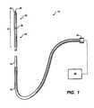
- FIG. 1shows an example of a microwave antenna assembly which may be utilized with the cooling systems described herein.
- FIGS. 2A and 2Bshow representative cross-sectional end and side views, respectively, of a microwave antenna assembly which may be utilized with the cooling systems described herein.
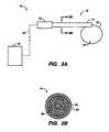
- FIG. 3Ashows a representative illustration of another variation of a microwave antenna assembly which may be utilized with the cooling systems described herein.
- FIG. 3Bshows a cross-sectional view of the antenna of FIG. 3A .
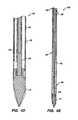
- FIGS. 4A and 4Bshow a cross-sectional side view and an end view, respectively, of one variation of an antenna cooling system.
- FIG. 4Cshows a detail view from FIG. 4A of the cooling system handle.
- FIGS. 4D and 4Eshow detail views from FIG. 4A of alternative cooling configurations for the antenna.
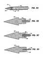
- FIG. 5Ashows a representative cross-sectional view of the distal end of the antenna within a cooling system.
- FIGS. 5B to 5Dshow cross-sectional side views of alternative attachments between the antenna and cooling system tip.
- FIG. 5Eshows a cross-sectional side view illustrating one variation in which the cooling system tip may be energized.
- FIG. 6shows a representative side view of another variation of the cooling system which may have an externally positioned fluid tube.
- FIG. 7shows a representative side view of yet another variation of the cooling system which may have an integrated fluid lumen defined within a wall of the outer jacket.
- FIG. 8shows a side view of yet another variation of the cooling system having a separate mandrel for structural support.
- FIGS. 9A to 9Cillustrate one variation in utilizing the device of FIG. 8 .
- FIG. 10shows yet another variation of a cooling system configured to be placed over only the radiating portion of a microwave antenna.
- FIG. 11shows yet another variation of a cooling system comprising a tube which may be coiled over the microwave antenna.
- FIGS. 12A and 12Bshow side and cross-sectional views, respectively, of a loop antenna variation configured to cool the antenna.
- FIGS. 13A to 13Cshow end, cross-sectional side, and perspective views, respectively, of another variation of the system configured as a cooling sheath.
- FIG. 14Ashows a sheath in one variation used with a straight probe microwave antenna.
- FIG. 14Bshows the sheath in another variation used with a looped probe microwave antenna.
- FIG. 14Cshows the sheath in yet another variation used with a looped probe microwave antenna configured to cool the radiating looped antenna portion.
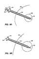
- FIG. 15shows a variation of a straight probe microwave antenna having a dilating balloon used to push surrounding tissue away from the antenna surface.
- FIG. 16shows another variation of a straight probe microwave antenna having multiple dilating balloons positioned along the length of the antenna.
- FIG. 17shows an exploded assembly view of another variation of the cooling system configured as a separate cooling sheath positionable over the microwave antenna shaft.
- FIG. 18shows a side view of yet another variation of a cooling sheath configured to conform at least partially to the tissue surface.
- FIGS. 19A and 19Bshow cross-sectional side and end views, respectively, of a cooling sheath.
- FIGS. 20A and 20Bshow cross-sectional side and end views, respectively, of another variation on the cooling sheath having a divider which may be breached to allow the intermixing of chemicals to create a cooling endothermic reaction.
- FIGS. 21A and 21Bshow cross-sectional side views of yet another variation on the cooling sheath in which slidable concentric tubes have openings which are alignable to allow for the intermixing of chemicals to create a cooling endothermic reaction.
- FIG. 21Cshows an end view of the cooling sheath of FIG. 21B where the openings are aligned.
- FIG. 22Ashows a perspective view of one example of a cooling sheath positioned over the microwave antenna.
- FIGS. 22B and 22Cshow perspective views of other variations of cooling sheaths having a number of fluid lumens defined between the sheath and antenna surface.
- FIG. 22Dshows a perspective view of another variation in which the dielectric between the inner and outer conductors may define a number of cooling lumens therethrough.
- FIG. 23Ashows a perspective view of a portion of a triaxial microwave antenna shaft.
- FIG. 23Bshows an example of cooling lumens which may be defined through the dielectric between the outer conductor and the choke layer.
- FIG. 24shows a side view of a straight microwave antenna probe delineating the various regions along the antenna shaft which may be in contact with various regions of tissue.
- FIG. 25shows yet another variation of a cooling system which may be configured to delineate multiple regions of varied cooling along the shaft of the microwave antenna.
- FIG. 26Ashows yet another variation in which a diameter of the coaxial cable may be non-uniform such that a larger cable may have improved power handling capabilities which facilitate a decrease in the generation of high temperatures.
- FIGS. 26B and 26Cshow cross-sectional side views of other transitional diameters for the inner conductor of FIG. 26A .
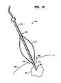
- FIG. 27shows a plot illustrating the temperature rise over time of an uncooled microwave antenna.
- FIG. 28shows a plot illustrating the decrease in microwave antenna temperature when the cooling system is activated.
- microwave antenna assemblies and cooling systemsare less traumatic than devices currently available and as described in further detail below.
- traumamay be caused to the patient resulting in pain and other complications.
- One cause of traumamay result from excess tissue being unnecessarily ablated by the microwave antenna assembly.
- the feedline or shaft of the antenna, as well as the radiation portionmay increase in temperature due to ohmic heating. Tissue in contact with a surface of the antenna may thus become charred or ablated unnecessarily. Aside from unnecessary trauma, charred tissue may decrease the effectiveness of the microwave antenna because of the changing impedance of the tissue as it dries out and becomes charred.
- the cooling systemsas described herein, may be used in conjunction with various types of microwave antennas.
- FIG. 1shows a representative diagram of a variation of a microwave antenna assembly 10 which may be used with a cooling system as described herein.
- the antenna assembly 10is generally comprised of radiating portion 12 which may be connected by feedline 14 (or shaft) via cable 16 to connector 18 , which may further connect the assembly 10 to a power generating source 30 , e.g., a generator.
- Assembly 10is a dipole microwave antenna assembly, but other antenna assemblies, e.g., monopole or leaky wave antenna assemblies, may also be utilized.
- Distal portion 22 of radiating portion 12preferably has a tapered end 26 which terminates at a tip 28 to allow for insertion into tissue with minimal resistance.
- tip 28may be rounded or flat.
- the antenna assembly 10 in FIG. 1shows a variation where a compressive load may be used to increase antenna strength.
- Proximal portion 24is located proximally of distal portion 22 , and junction member 20 is preferably located between both portions such that a compressive force is applied by distal and proximal portions 22 , 24 upon junction member 20 .
- Placing distal and proximal portions 22 , 24 in a pre-stressed condition prior to insertion into tissueenables assembly 10 to maintain a stiffness that is sufficient to allow for unaided insertion into the tissue while maintaining a minimal antenna diameter, as described in detail below.
- Feedline 14may electrically connect antenna assembly 10 via cable 16 to generator 30 and usually comprises a coaxial cable made of a conductive metal which may be semi-rigid or flexible. Feedline 14 may also have a variable length from a proximal end of radiating portion 12 to a distal end of cable 16 ranging between about 1 to 15 inches. Most feedlines may be constructed of copper, gold, or other conductive metals with similar conductivity values, but feedline 14 is preferably made of stainless steel. The metals may also be plated with other materials, e.g., other conductive materials, to improve their properties, e.g., to improve conductivity or decrease energy loss, etc.
- a feedline 14such as one made of stainless steel, preferably has an impedance of about 50 ⁇ and to improve its conductivity, the stainless steel may be coated with a layer of a conductive material such as copper or gold. Although stainless steel may not offer the same conductivity as other metals, it does offer strength required to puncture tissue and/or skin.
- FIGS. 2A and 2Bshow an end view and a cross-sectional view, respectively, of a conventional dipole microwave antenna assembly 40 which may be utilized with the cooling systems described herein.
- antenna assembly 40has a proximal end 42 which may be connected to a feedline 14 and terminates at distal end 44 .
- the radiating portion of antenna 40comprises proximal radiating portion 46 and distal radiating portion 48 .
- Proximal radiating portion 46may typically have an outer conductor 52 and an inner conductor 54 , each of which extends along a longitudinal axis. Between the outer and inner conductors 52 , 54 is typically a dielectric material 56 which is also disposed longitudinally between the conductors 52 , 54 to electrically separate them.
- a dielectric materialmay constitute any number of appropriate materials, including air.
- Distal portion 58is also made from a conductive material, as discussed below.
- Proximal and distal radiating portions 46 , 48align at junction 50 , which is typically made of a dielectric material, e.g., adhesives, and are also supported by inner conductor 54 which runs through junction opening 60 and at least partially through distal portion 58 .
- inner conductor 54which runs through junction opening 60 and at least partially through distal portion 58 .
- the construction of conventional antenna assembly 40is structurally weak at junction 50 .
- Microwave antenna assembly 70may comprise at least one microwave antenna 72 electrically connected to generator 82 .
- Microwave antenna 72preferably comprises shaft or feedline 74 with a distal end from which antenna or inner conductor 76 extends to define the ablation region 90 .
- the proximal end of feedline 74preferably comprises coupler 78 which electrically couples the antenna 72 to generator 82 via power transmission cable 80 .
- the cable 80is preferably a flexible cable which allows for the positioning of antenna 72 relative to a patient.
- Feedline 74is preferably a coaxial cable, as shown by the cross-section 3 B- 3 B in FIG. 3B taken from FIG. 3A .
- the feedline 74may be formed of outer conductor 84 surrounding inner conductor 86 .
- Conductors 84 , 86may be made of a conductive metal which may be semi-rigid or flexible.
- Most feedlines 84as described above, may be constructed of metals such as stainless steel. Alternatively, metals such as copper, gold, or other conductive metals with similar conductivity values may also be utilized.
- a dielectric material 88is preferably disposed between outer and inner conductors 84 , 86 , respectively, to provide insulation therebetween and may be comprised of any appropriate variety of conventional dielectric materials.
- FIGS. 4A and 4Bshow a cross-sectional side view and an end view, respectively, of one variation of an antenna cooling system which may be utilized with any number of conventional microwave antennas or the microwave antennas described herein, particularly the straight probe configuration as shown in FIGS. 1 and 2A-2B .
- Antenna cooling assembly 100may generally comprise a cooling handle assembly 102 and an elongate outer jacket 108 extending from handle assembly 102 . Outer jacket 108 may extend and terminate at tip 110 , which may be tapered to a sharpened point to facilitate insertion into and manipulation within tissue, if necessary.
- Microwave antenna 104may be positioned within handle assembly 102 such that the radiating portion 106 of antenna 104 extends distally into outer jacket 108 towards tip 110 .
- Inflow tubing 114may extend into a proximal end of handle body 112 and distally into a portion of outer jacket 108 .
- Outflow tubing 116may also extend from within handle body 112 such that the distal ends of inflow tubing 114 and outflow tubing 116 are in fluid communication with one another, as described in further detail below.
- FIG. 4Cshows handle assembly detail 118 from FIG. 4A .
- handle body 112may be comprised of proximal handle hub 122 , which encloses a proximal end of antenna 104 , and distal handle hub 124 , which may extend distally into outer jacket 108 .
- Proximal handle hub 122 and distal handle hub 124may each be configured to physically interfit with one another at hub interface 130 to preferably form a fluid tight seal.
- proximal handle hub 122may be configured to be received and secured within a correspondingly configured distal handle hub 124 , seen in the figure as a male-female connection.
- Proximal and distal handle hubs 122 , 124may each be formed from the same (or similar) or different materials. If hubs 122 , 124 are fabricated from the same material, a variety of non-conductive materials are preferably utilized, e.g., polymers, polyimides, plastics, etc. Alternatively, proximal handle hub 122 may be fabricated from a metal or alloy, e.g., stainless steel, platinum, nickel, nickel-titanium, etc., while distal handle hub 124 (or just the handle portion over the radiating portion of the microwave antenna) may be fabricated from one of the non-conductive materials previously mentioned.
- a metal or alloye.g., stainless steel, platinum, nickel, nickel-titanium, etc.
- inflow tubing 114 and outflow tubing 116may be positioned within handle body 112 such that fluid may be pumped into handle body 112 via a pump (not shown) through inflow tubing 114 .
- Fluid entering handle body 112may come into direct contact with at least a portion of the shaft of antenna 104 to allow for convective cooling of the antenna shaft to occur.
- the fluidmay be allowed to exit handle body 112 via outflow tubing 116 .
- An additional inlet tube 126may be positioned within antenna cooling assembly 100 to extend between handle body 112 and radiating portion 106 of antenna 104 and a corresponding outlet tube 128 may also extend between handle body 112 and radiating portion 106 .
- inlet tube 126may be in fluid communication with inflow tubing 114 to allow the cooling fluid to flow distally within outer jacket 108 towards antenna radiation portion 106 .
- inlet tube 126 and outlet tube 128may be omitted from cooling assembly 100 and outer jacket 108 may remain in direct fluid communication with inflow tubing 114 and outflow tubing 116 such that fluid contacts the antenna 104 directly along a portion of the length, or a majority of the length, or the entire length of antenna 104 .
- the cooling assembly 100is effective in cooling the antenna 104 directly rather than cooling the tissue surrounding the antenna 104 , although the surrounding tissue may also be conductively cooled via assembly 100 .
- FIGS. 4D and 4Eshows outer jacket detail variations 120 , 120 ′, respectively, from FIG. 4A
- FIG. 4Dshows one variation where the distal end 132 of inlet tube 126 may extend distally through outer jacket 108 .
- the opening at distal end 132may be positioned within outer jacket 108 near or at the distal end of outer jacket 108 such that distal end 132 opens to fluid channel 134 .
- the cooling fluidmay enter fluid channel 134 and fill the volume surrounding at least a portion of the antenna 104 , and preferably surrounding at least the radiation portion 106 .
- fluid channel 134As fluid enters fluid channel 134 , it may be withdrawn through a distal opening in outlet tube 128 , which is preferably located proximally of distal end 132 to allow for increased convective cooling between the cooling fluid and the antenna 104 .
- each of the distal ends of inlet tube 126 and outlet tube 128may be aligned with one another.
- the cooling fluidmay directly contact the outer surface of the antenna 104 and envelope the antenna 104 rather than being in conductive contact through some additional thermal interface. Allowing the direct fluid-to-antenna contact enables direct convective cooling to occur and may thereby facilitate the heat transfer from the antenna to the cooling fluid.
- the cooling fluidmay be pumped using positive pressure through inlet tube 126 ; alternatively, negative pressure may also be used to draw the fluid out of the region through outlet tube 128 . Negative pressure through outlet tube 128 may be utilized either alone or in conjunction with positive pressure through inlet tube 126 . Alternatively, positive pressure through inlet tube 126 may be utilized either alone or in conjunction with negative pressure through outlet tube 128 .
- the cooling fluidmay be passed through assembly 100 at a constant and uniform flow rate. In another variation, the flow may be intermittent such that a volume of cooling fluid may be pumped into fluid channel 134 and allowed to warm up by absorbing heat from the antenna.
- the warmed fluidmay be removed and displaced by additional cooling fluids.
- Temperature sensors(such as thermistors, thermocouples, etc.) may be incorporated within or upon the outer jacket 108 to sense the fluid and/or outer jacket 108 temperatures.
- the systemmay be configured to automatically pump additional cooling fluid into cooling assembly 100 once the sensed temperature reaches the predetermined level or it may be configured to notify the user via, e.g., an audible or visual alarm.
- the cooling fluid usedmay vary depending upon desired cooling rates and the desired tissue impedance matching properties.
- biocompatible fluidshaving sufficient specific heat values for absorbing heat generated by microwave ablation antennas may be utilized, e.g., liquids including, but not limited to, water, saline, Fluorinert®, liquid chlorodifluoromethane, etc.
- gasessuch as nitrous oxide, nitrogen, carbon dioxide, etc.
- an aperturemay be configured at the opening of distal end 132 to take advantage of the cooling effects from the Joule-Thompson effect, in which case a gas, e.g., nitrous oxide, may be passed through the aperture to expand and cool the enclosed antenna 104 .
- a combination of liquids and/or gasesas mentioned above, may be utilized as the cooling medium.
- FIG. 4Eshows another variation in detail 120 ′ within outer jacket 108 which incorporates a barrier or gasket 138 to separate the radiating portion 142 of antenna 106 from a proximal portion of the antenna shaft.
- Barrier 138may be, e.g., a polymeric or rubber material, configured to function as a gasket to maintain a fluid tight seal around the shaft of the antenna 106 .
- Fluid channel 140may be defined within outer jacket 108 distally of barrier 138 within which radiating portion 142 may be positioned.
- a fluidsuch as any one of the fluids mentioned above, may be maintained statically within fluid channel 140 to absorb heat generated by radiating portion 142 .
- channel 140may be filled with a fluid, high-temperature chemical, e.g., epoxy, for better impedance matching with the antenna 106 .
- a separate fluid channelmay be defined proximally of barrier 138 surrounding the remaining shaft portion of the antenna.
- An inlet tube 136may be positioned within this proximal channel to allow for the exchange of cooling fluids therewithin in a manner as described above such that the fluid is allowed to directly contact the antenna shaft surface.
- FIG. 5Ashows an illustrative cross-sectional view of cooling assembly distal end 150 which shows microwave antenna 154 positioned within outer jacket 152 .
- antenna 154may remain either electrically or mechanically unconnected to cooling assembly tip 156 , the two may optionally be joined via a connection 158 .
- FIG. 5Bshows one variation of connecting antenna 154 to tip 156 in which they may be mechanically and electrically connected.
- Tip 156may be fabricated from a metal or alloy, e.g., stainless steel, and define a contact channel at its proximal end for receiving antenna 160 , which may also be metallic.
- Antenna end 160may be secured into an electrically conductive connection 162 with tip 156 through various mechanical fastening methods, e.g., adhesives, welding, soldering, clamping, crimping, press-fit, etc., such that connection 162 is a mechanical joint sufficiently strong enough to resist failure when deployed into tissue while also providing for an electrical connection.
- various mechanical fastening methodse.g., adhesives, welding, soldering, clamping, crimping, press-fit, etc.
- FIG. 5Cshows another variation where antenna 164 may be mechanically connected to but electrically insulated from tip 156 .
- Antenna 164or at least the portion of antenna 164 in contact with tip 156 , may have an insulative layer 166 over its outer surface.
- tip 156may remain electrically insulated from antenna 164 yet retain the structural connection therebetween, as described above.
- FIG. 5Dshows a connection in which antenna 154 may be electrically connected to tip 156 via a wire or cable 168 . Such a connection may be used to provide for electrical communication between antenna 154 and tip 156 but does not provide for structural support between the two.
- FIG. 5Eshows a variation where electrical communication with tip 156 may be maintained with an externally located power source 161 to provide power for energizing tip 156 .
- Energized tip assembly 151shows antenna 164 structurally connected to tip 156 with insulative layer 166 positioned therebetween.
- Antenna 164is shown positioned within outer jacket 153 .
- wire 159may be connected to choke 155 such that power source 161 is electrically connected to tip 156 through choke 155 , in an alternative variation.
- power source 161may instead be electrically connected to tip 156 via outer conductor 157 through wire 159 .
- wire 159is connected to either choke 155 or outer conductor 157 , an electrical connection between antenna 164 and tip 156 is present.
- FIG. 6shows a side view of another cooling assembly variation 170 .
- outer jacket 172may have an inlet tube 176 externally located from the lumen of outer jacket 172 .
- Tube 176may be fabricated from the same or similar material as outer jacket 172 , as described above, or it may be made from a material different from outer jacket 172 , provided that it is preferably non-electrically conductive.
- Tube 176may be a completely separate tube member attached to the surface of outer jacket 172 .
- tube 176may be integrally formed with outer jacket 172 .
- cooling fluidmay be pumped through tube 176 to flow distally along outer jacket 172 , as shown by the arrows, until it passes through opening 180 , which may allow for the fluid communication between tube 176 and outlet channel 178 defined through the interior of outer jacket 172 .
- Opening 180may be defined between tube 176 and outlet channel 178 at a predetermined location along outer jacket 172 proximal to tip 174 . The location of opening 180 may depend upon the desired cooling effects and the desired location along the antenna over which the cooling fluid may flow.
- the cooling fluidmay be pumped into cooling jacket 172 through outlet channel 178 and the discharged fluid may be returned through tube 176 .
- FIG. 7shows a side view of another cooling assembly variation 190 .
- Outer jacket 192may be seen with tip 194 at its terminal end.
- inlet lumen 196may be defined directly within the wall of outer jacket 192 .
- Inlet lumen 196may terminate at opening 200 which may be in fluid communication with outlet channel 198 , within which a microwave antenna may be situated.
- opening 200is shown terminating at the distal end of outer jacket 192
- opening 200may be defined at some predetermined location along outer jacket 192 proximal to tip 194 between inlet lumen 196 and outlet channel 198 .
- outer jacket 192may be fabricated out of any one of the materials as described above.
- Cooling introducer assembly 210may comprise a polymeric tubing 212 having tubing hub 214 located at the proximal end of tubing 212 .
- Tip 216which may be tapered to facilitate assembly 210 introduction into tissue, may be located at the distal end of tubing 212 .
- a removable elongate mandrel 218may be inserted within tubing 212 to provide structural support and column strength to tubing 212 during insertion of assembly 210 into tissue.
- Mandrel 218may be fabricated from various materials having sufficient strength to withstand bending moments generated by tubing 212 during tissue insertion, e.g., stainless steel, and may be configured to slidably fit within lumen 220 .
- FIGS. 9A to 9Cshow one example of how assembly 210 may be used as an introducer and cooling jacket for the ablative treatment of tissue.
- Tubing 212with mandrel 218 positioned within, may be inserted into the tissue of a patient 230 until a distal portion of tubing 212 is positioned adjacent to or within a diseased region of tissue, e.g., tumor 232 , as shown in FIG. 9A .
- inner mandrel 218may be removed from tubing 212 while maintaining the position and orientation of tubing 212 within patient 230 , as shown in FIG. 9B .
- Microwave antenna 236may then be inserted within lumen 220 of tubing 212 and advanced distally therewithin such that radiating portion 238 of antenna 236 is positioned within the distal portion of tubing 212 which is adjacent to or within tumor 232 .
- the proximal end of antenna 236may have cooling hub 234 connected thereto and cable 240 extending proximally for connection to a microwave and/or RF power supply (not shown).
- the length of antenna 236may be configured to fit within tubing 212 such that tubing hub 214 and cooling hub 234 may come into contact with one another and locked together, as shown in FIG. 9C .
- One or both hubs 214 , 234may be configured to releasably lock together through any method of mechanical attachment.
- hubs 214 , 234may be threaded to screw onto one another, or hubs 214 , 234 may be configured to be secured via an interference fit, or any other mechanical fastening method known in the art may be utilized.
- a gasketmay be provided to fit in-between hubs 214 , 234 to provide for a fluid-tight seal therebetween.
- Cooling hub 234may be fluidly connected to a pump via inlet tube 242 and outlet tube 244 . Once hubs 214 , 234 have been secured together, cooling fluid may be introduced through inlet tube 242 and through hub 234 such that the fluid enters into lumen 220 to envelope and contact antenna 236 to cool antenna 236 , if desired. The fluid may be removed from lumen 220 via outlet tube 244 , which may also be in fluid communication with lumen 220 via hub 234 . Once the procedure has been completed, the entire assembly may be removed from the tissue.
- cooling jacket 256may be modified to cover only the radiating portion 254 of the microwave antenna. Cooling jacket 256 may thus be configured to be shortened in length from, e.g., cooling jacket 108 described above, and may further omit a handle portion to form cooling channel 262 around radiating portion 254 . Inlet tube 258 and outlet tube 260 may be incorporated with jacket 256 to provide the cooling fluid flow within cooling jacket 256 . The remainder of antenna shaft 252 may remain uncovered by cooling jacket 256 .
- FIG. 11shows another variation in cooling assembly 270 in which antenna shaft 272 may have cooling tube 276 coiled around at least a portion of shaft 272 .
- Cooling tube 276may have cooling fluid flowing therethrough via inlet tube 278 and outlet tube 280 connected to a pump.
- tube 276is coiled around a portion of antenna shaft 272 up to radiating portion 274 .
- tube 276may also be coiled around radiating portion 274 , in which case tube 276 , or the portion of tube 276 covering radiating portion 274 , is preferably fabricated from a polymeric or plastic material.
- tube 276may be coiled only over radiating portion 274 .
- An optional covering or sheathpreferably made from a polymeric material, e.g., PTFE, Pebax®, etc., may be formed or fitted over the coiled tube 276 (or a portion of the coiled tube 276 ) to provide a lubricious surface for assembly 270 for insertion into tissue.
- a polymeric materiale.g., PTFE, Pebax®, etc.
- FIGS. 12A and 12Bshow side and cross-sectional views, respectively, of a loop antenna variation 290 configured to cool the antenna.
- This variationis shown for a microwave antenna having a looped antenna, but the principles are applicable to straight antenna probes, as will be described in further detail below.
- antenna shaft 292may have fluid outer tube 294 positioned within antenna shaft 292 and fluid inner tube 296 coaxially positioned within outer tube 294 .
- the assembly of tubes 294 , 296may form inner conductor assembly 298 and each tube may extend through the length of antenna shaft 292 and beyond to form the curved antenna portion.
- the distal end of fluid inner tube 296may terminate proximally of the distal end of fluid outer tube 294 , which is preferably enclosed at its terminal end.
- the distal end of fluid inner tube 296may also define an opening to allow for fluid communication between tubes 294 , 296 .
- Fluid inner tube 296may define an inflow lumen 300 , as shown in FIG. 12B
- fluid outer tube 294may define an outflow lumen 302 in the space between tubes 294 , 296 .
- cooling fluidmay be circulated through the inner conductor 298 itself to cool the antenna during microwave energy transmission.
- Tubes 294 , 296may be formed from an electrically conductive material suitable for microwave transmission, e.g., stainless steel, platinum, gold, nickel, etc., or stainless steel plated with an electrically conductive material having a lower electrical resistivity than the stainless steel.
- Sheath assembly 310may generally comprise main tubular member 312 which defines an antenna lumen 316 therethrough.
- Tubular member 312may be fabricated of a polymeric or plastic material, as described above, and preferably defines a diameter sufficient to accommodate the shaft of a microwave antenna positioned within antenna lumen 316 .
- tubular member 312may be at least partially formed of a metallic material (preferably proximal to the radiating portion), or member 312 may be formed of a ceramic material.
- Tubular member 312is preferably wide enough to allow for direct contact or close contact against an outer surface of the microwave antenna when the antenna is positioned within to facilitate the heat transfer.
- the tubular member 312may also be formed of a material, e.g., heat-shrink polymers, which allow for tubular member 312 to conform to an outer surface of the microwave antenna to ensure close thermal contact.
- a thermally conductive and conformable materialsuch as a gel or fluid, may be poured or placed within the space, if present, between antenna lumen 316 and the inner wall of tubular member 312 to ensure consistent thermal contact between the two.
- a coaxially positioned fluid tube 314may be positioned around tubular member 312 and define fluid channel 322 , as seen in the cross-sectional view of FIG. 13B .
- Fluid tube 314may be formed as a common channel such that fluid contained therewithin envelopes or encompasses the outer surface of tubular member 312 .
- Fluid tube 314may also be varied in length to surround a majority of tubular member 312 or just a portion of it depending upon the desired cooling effects.
- Inlet tube 318may be positioned within fluid channel 322 such that the distal end of inlet tube 318 is positioned near or at the distal end of fluid tube 314 while the distal end of outlet tube 320 may be positioned near or at the proximal end of fluid tube 314 to facilitate the heat transfer.
- Fluid tube 314may be integrally fabricated with tubular member 312 ; however, fluid tube 314 may also be made of a material different from tubular member 312 and attached through one of any mechanical fastening methods.
- fluid channel 322may be formed as a common circumferential fluid channel. If cooling sheath assembly 310 is positioned over only the shaft portion of a microwave antenna, assembly 310 may be made from a metallic material such as stainless steel.
- assembly 310is also configured to be positioned over the radiating portion of an antenna, the entire assembly 310 , or at least the portion of the assembly 310 covering the antenna, is preferably made from a polymeric or plastic material, as described above.
- the distal end of assembly 310may be formed into a tapered or atraumatic end 324 to prevent damage to surrounding tissue when assembly 310 is inserted into a patient.
- FIG. 14Ashows a side view of a cooling sheath assembly in one variation 330 used with a straight probe microwave antenna.
- assembly 330may comprise cooling sheath 332 for placement over a length of antenna shaft 344 .
- the radiating portion 342is uncovered in this variation, although alternative sheath designs may be employed to entirely cover the radiating portion 342 as well.
- Assembly 330may also comprise hub 334 , through which inlet tube 338 and outlet tube 340 may be in fluid communication with sheath 332 to allow for circulation of the cooling fluid.
- An optional adjustable seeming membere.g., tightening knob 336
- Knob 336may be untightened as well to allow for removal or adjustment of sheath 332 over the antenna.
- Tightening knob 336is shown as a rotatable securing mechanism, e.g., a tightening screw, however, other tightening methods as known in the art may be employed for securing sheath 332 to antenna shaft 344 .
- FIG. 14Bshows a side view of the cooling sheath assembly of FIG. 14A in another variation 350 in which sheath 332 may be placed over the shaft 356 of a microwave antenna having a looped radiating portion 354 .
- sheath 332may be positioned over shaft 356 such that the portion of shaft 356 up to its distal end 352 is covered. Radiating portion 354 may remain uncovered in this variation.
- FIG. 14Cshows the cooling sheath assembly in yet another variation 360 used with a looped microwave antenna configured to cool the radiating looped antenna portion.
- sheath 332may be used with a looped microwave antenna having an inner conductor configured to have cooling lumens integrated within, as shown and described for FIGS. 12A and 12B above.
- a separate cooling balloon or sheath 362may be formed to surround the radiating portion 354 .
- Balloon or sheath 362is described in further detail in U.S. Pat. No. 7,197,363, which has been incorporated herein above.
- balloon or sheath 362may be disposed over the curved radiating portion 354 of the microwave antenna.
- Balloon or sheath 362may be in a deflated state during the deployment of the antenna through sheath 332 and/or within the tissue, but once the curved antenna 354 has been desirably positioned, balloon 362 may be filled with the cooling fluid, e.g., chilled saline, water, etc., until it has sufficiently inflated.
- the cooling fluide.g., chilled saline, water, etc.
- the size of balloon 362may be varied according to the desired radiative effects (for impedance matching purposes), the length of radiating portion 354 , as well as the type of tissue which the antenna is inserted within. Furthermore, the cooling fluid may be maintained statically within balloon 362 or it may be circulated in a manner as described above.
- FIG. 15Another alternative for cooling a microwave antenna and/or preventing unnecessary tissue damage by a heated antenna feedline or shaft is seen in FIG. 15 .
- the variation shownis a passively cooled balloon assembly 370 which may typically comprise microwave antenna shaft or feedline 372 with an inflatable balloon 374 positioned over a length of shaft 372 .
- FIG. 15shows balloon 374 in an inflated configuration over the microwave antenna.
- a balloon member 374which may be inflatable with a liquid or gas (or combination of both) such as saline, water, air, nitrogen, etc., may be attached along microwave antenna shaft 372 at proximal attachment region 376 and distal attachment region 378 through any variety of attachment methods, e.g., adhesives, crimping, etc.
- a separate inflatable balloonmay simply be placed over antenna shaft 372 and reside unattached to the microwave antenna.
- Balloon 374may reside along shaft 372 to cover the portion of the shaft 372 which may come into contact with tissue when inserted into a patient.
- Distal attachment region 378may be positioned proximally of antenna radiating portion 380 such that the entire radiating portion 380 is not covered by balloon 374 .
- distal attachment region 378may be positioned near or at the distal tip of the antenna so that a portion, or a majority of radiating portion 380 , is at least partially covered by balloon 374 .
- the microwave antennamay be advanced percutaneously or laparoscopically through the skin 382 of a patient to position antenna radiating portion 380 near or adjacent to tumor 384 .
- Balloon 374is preferably in a deflated configuration during the insertion through the skin 382 , although balloon 374 may alternatively be inflated prior to or during insertion through skin 382 , depending upon the circumstances.
- balloon 374may be inflated via an inlet tube prior to or during microwave energy transmission through the antenna. The inflation of balloon 374 may dilate the tissue 386 surrounding the shaft 372 and urge the tissue 386 out of contact with shaft 372 .
- the radiating portion 380may remain in direct contact with tumor 384 to effect microwave ablation treatment. Having balloon 374 move tissue 386 away from direct contact with antenna shaft 372 helps to prevent the tissue 386 from overheating or becoming ablated.
- the microwave antenna assembly 390may be divided into several, i.e., two or more, regions along its shaft.
- first antenna region 392 , second antenna region 394 , and third antenna region 396may each have a respective first balloon 400 , second balloon 402 , and third balloon 404 over each region such that each balloon 400 , 402 , 404 is adjacent to one another along the shaft outer surface.
- Each balloon 400 , 402 , 404may be attached to the microwave antenna distal of connector hub 414 at first, second, third, and fourth attachment regions 406 , 408 , 410 , 412 , respectively, through one of any attachment methods as described above.
- a balloonmay be positioned over radiating portion 398 or radiating portion 398 may be left exposed, as shown in the figure.
- the number of balloons in this exampleare merely illustrative and fewer or greater number of balloons may be utilized depending upon the desired configuration and cooling results.
- each balloon 400 , 402 , 404may be in fluid communication with one another in series such that all the balloons 400 , 402 , 404 may be inflated simultaneously.
- each balloon 400 , 402 , 404may be individually inflatable such that a single balloon, or a combination of balloons, may be inflated while the other balloons may remain un-inflated, depending upon the desired cooling results.
- each balloonmay be inflatable with a liquid or gas (or combination of both) such as saline, water, air, nitrogen, etc., as described above.
- a liquid or gassuch as saline, water, air, nitrogen, etc., as described above.
- a straight microwave antenna probeis shown in the figures, this is intended to be illustrative; alternatively, a microwave antenna having a curved radiating portion may also be utilized.
- Assembly 420may comprise a microwave antenna 422 having a radiating portion 424 ; in this example, a curved radiating portion 424 .
- a tubular cooling pack 426may define a lumen 428 into which the shaft of antenna 422 may be positioned. Both antenna 422 and cooling pack 426 may be positioned within a handle lumen 434 defined within handle 430 .
- An optional insulation layer 432e.g., foam, rubber, etc., may be disposed upon the inner surface of handle lumen 434 between cooling pack 426 and handle 430 .
- Cooling pack 426may simply be a plastic or polymeric tubular container of chilled or frozen water or saline, or another fluid which is preferably biocompatible, which may be cooled prior to use with the microwave antenna.
- cooling pack 426may contain gels or chemicals which may be mixed (e.g., a mixture of water, urea, and ammonium chloride; alternatively, a mixture of potassium chloride or sodium nitrate and water, etc.) such that an endothermic reaction results and cooling of the antenna 422 may be achieved.
- cooling pack 426may be configured to come into intimate contact with the shaft of antenna 422 to ensure good thermal contact.
- Handle 430may be molded from various materials, e.g., polymers, plastics, etc., and it may be configured as a simple tubular handle. Alternatively, it may be ergonomically molded to allow for better handling by the user.
- the handle lumen 434is preferably just wide enough to allow for the insertion of cooling pack 426 so that thermal contact between the two may occur.
- the cooling assembly 420may be assembled prior to use with the antenna 422 such that the entire assembly is inserted into the tissue altogether; alternatively, it may be assembled within the tissue during tissue ablation.
- conformable cooling sheath assembly 440may be inserted through a handle lumen 450 defined through conformable cooling sheath 440 .
- Cooling sheath 440may comprise a proximal handle portion 444 and a conformable portion 446 which may be configured to spread over and cool the skin surface 452 surrounding the area where the antenna shaft 442 has been inserted.
- Proximal handle portion 444may be comprised of a polymeric or plastic material which may be adapted to maintain its configuration while conformable portion 446 may be comprised of a polymeric material adapted to spread out and conform against skin surface 452 over contact surface 448 .
- Conformable sheath assembly 440may be filled with any one of the liquids, gases, and/or chemical mixtures as described above.
- FIGS. 20A to 21CAlternative cooling sheaths are further shown in FIGS. 20A to 21C .
- a cross-sectional side and end view of cooling sheath 460is shown in FIGS. 19A and 19B , respectively, for comparison purposes.
- a simple cooling sheath 460as described above, may define antenna lumen 462 therethrough.
- FIGS. 20A and 20Bshow cross-sectional side and end views of cooling sheath 470 .
- Antenna lumen 474may be defined through the length of sheath 470 .
- Barriers 472may be defined through the length of sheath 470 to divide the interior lumen into at least two separate volumes.
- a first defined volume 476may hold a first chemical or liquid (e.g., water, saline, etc.) and second defined volume 478 may hold a second chemical or liquid (ammonium chloride, sodium nitrate, or potassium chloride, etc.).
- first chemical or liquide.g., water, saline, etc.
- second defined volume 478may hold a second chemical or liquid (ammonium chloride, sodium nitrate, or potassium chloride, etc.).
- sheath 470may be flexed slightly such that barriers 472 may be broken or fractured within sheath 470 to allow for the mixing between the chemicals from first volume 476 and second volume 478 to result in an endothermic reaction.
- sheath assembly 480may comprise an inner tube 484 , which defines a first volume 492 for holding a first chemical or liquid, and a concentric outer tube 482 , which defines a second volume 494 for holding a second chemical or liquid.
- the composition of the first chemical and/or second chemical contained in their respective volumesmay include any of the chemicals and/or liquids mentioned above.
- Outer tube 482may define a plurality of openings 488 over its inner surface and inner tube 484 may also define a plurality of openings 490 over its outer surface.
- Openings 488 , 490may be defined in each of their respective tubes such that when inner tube 484 and outer tube 482 are in a first misaligned configuration relative to one another, their respective openings are blocked, as shown in FIG. 21A . However, inner tube 484 and outer tube 482 may be moved longitudinally and/or rotationally relative to one another into a second aligned configuration such that openings 488 , 490 may be aligned with one another and allow for the mixing of the respective chemicals to produce a cooling effect within antenna lumen 486 , as shown in FIGS. 21B and 21C . These variations are intended to be illustrative and any variations on the number of openings or the manner in which openings may be aligned to allow for the mixture of various chemicals or liquids are intended to be within the scope of the invention.
- FIG. 22Ashows a perspective view of a portion of a microwave antenna shaft assembly 500 in which outer tubing 508 may be formed as an integral part of the microwave antenna.
- the antennais shown as comprising, in part, outer conductor 502 coaxially surrounding inner conductor 504 with dielectric 506 disposed therebetween.
- Outer tubing 508which may be comprised of a metallic, e.g., stainless steel, or polymeric material, as described above, may surround the length, or at least a partial length of the microwave antenna.
- Outer tubing 508may define a cooling lumen 510 between the outer conductor 502 through which a cooling fluid may be pumped through or simply filled.
- FIG. 22Bshows another cooling tube variation 520 in which outer tubing 522 may surround the microwave antenna, as in assembly 500 of FIG. 22A .
- Tubing 522may include a barrier or divider 524 which separates the cooling lumen into at least a first lumen 526 and a second lumen 528 , which may act as inlet and outlet lumens, respectively, for a cooling fluid to be flowed through.
- Divider 524may be formed of the same or similar material as outer conductor 502 and/or outer tubing 522 .
- outer tube 532may comprise a number of longitudinally formed dividers 534 , 536 , 538 , 540 , and 542 to create a number of corresponding cooling lumens 544 , 546 , 548 , 550 , and 552 in the space between outer conductor 502 and outer tubing 532 .
- the cooling lumensmay be utilized as inlet lumens or outlet lumens or various combinations thereof depending upon the desired cooling results.
- the number of dividers and cooling lumensis intended merely to be illustrative of the various combinations and numbers of cooling lumens which may be formed.
- FIG. 22Dshows yet another variation 560 in which cooling lumens may be formed within the space between outer conductor 502 and inner conductor 504 , where a dielectric material is typically located.
- longitudinally defined dividers 564 , 566 , 568 , 570 , and 572may be formed of an electrically non-conductive material, e.g., polymers, to divide the space into a number of corresponding cooling lumens 574 , 576 , 578 , 580 , and 582 .
- An optional cooling tube 562may be utilized and positioned over outer conductor 502 .
- the cooling lumensmay be utilized as inlet lumens or outlet lumens or various combinations thereof depending upon the desired cooling results.
- the number of dividers and cooling lumensis intended merely to be illustrative and not limiting in scope.
- an electrical chokemay be utilized to improve the energy focus of an antenna assembly.
- the electrical choke and its useis described in further detail in U.S. Pat. Nos. 6,878,147 and 7,128,739, which have been incorporated herein by reference above.
- the chokemay be disposed on the antenna proximally of the radiating section.
- the chokeis preferably placed over a dielectric material which may be disposed over the antenna.
- the chokeis preferably a conductive layer and may be further covered by a tubing or coating.
- a cross-sectional view of a triaxial antenna 590may be seen in FIG. 23A having inner conductor 592 and outer conductor 594 with dielectric 596 disposed therebetween.
- FIG. 23Bshows a cooling choke variation 610 in which a number of longitudinally defined dividers 612 , 614 , 616 , 618 , and 620 may form a number of corresponding cooling lumens 622 , 624 , 626 , 628 , and 630 .
- the dividersmay be formed of an electrically non-conductive material, e.g., polymers, and the cooling lumens may be utilized as inlet lumens or outlet lumens or various combinations thereof depending upon the desired cooling results.
- Cooling sheaths or jacketsmay be varied or tuned to match the requisite cooling for a given length of a microwave antenna.
- a typical microwave antennamay generally be divided into at least three different regions along the length of its shaft. For instance, in FIG. 24 , a side view of microwave antenna 640 may be seen divided into a first region 642 , second region 644 , and third region 646 .
- First region 642may generally comprise the radiating antenna or the region of active heating during microwave ablation. It may be desirable to cool this region 642 to maintain optimal energy delivery by preventing the surrounding tissue from charring, which in turn may change the effective wavelength.
- Second region 644is generally the portion of antenna 640 which is in contact with the tissue surrounding a tumor or lesion to be ablated.
- This region 644typically becomes hot from ohmic heating and some conductive heating from first region 642 . It may be desirable to allow second region 644 to heat up in certain tissue regions where coagulation of the insertion tract may be desirable. However, it may also be desirable to cool this region 644 in other applications to protect surrounding sensitive tissue structures from heat damage.
- third region 646is generally the portion of antenna 640 which comes into contact with the skin of a patient. This region 646 typically heats up because of ohmic heating and it is generally desirable to keep this region cool when used in percutaneous or laparoscopic procedures to prevent heat damage to the skin surface. In other procedures, such as in applications where lesions are located deep within the tissue, it may be desirable to allow region 646 to become heated to allow for the coagulation of the insertion tract.
- a multi-zone cooling assembly 650such as the variation shown in FIG. 25 , may be utilized to take advantage of optionally cooling multiple regions along the length of a microwave antenna.
- Cooling jacket 652may surround the length of microwave antenna 660 and define a smooth outer surface for insertion into tissue.
- the interior of cooling jacket 652may define a distal first cooling region 654 , second cooling region 656 , and a proximal third cooling region 658 .
- cooling regions 654 , 656 , 658may correspond to and envelope the various regions of antenna 660 , e.g., first region 662 may be positioned within first cooling region 654 , second region 664 may be positioned within second cooling region 656 , and third region 666 may be positioned within third cooling region 658 .
- Each of the cooling regions 654 , 656 , 658may be divided from one another when antenna 660 is positioned within cooling jacket 652 via, e.g., electrically insulative gaskets such as rubber or polymers, to prevent fluid communication between the adjacent cooling regions.
- first divider 680may separate first and second cooling regions 654 , 656 ; second divider 682 may separate second and third cooling regions 656 , 658 ; and third divider 684 may separate third cooling region 658 from the remainder of cooling jacket 652 .
- each individual cooling regionmay thus be maintained at a different cooling rate than from an adjacent cooling region, depending upon the desired cooling profile.
- any of the various cooling methods described hereinmay be utilized; in particular, each cooling region may utilize its own fluid inlet and outlet tubes.
- first cooling region 654may have a first inlet tube 668 and first outlet tube 670 ;
- second cooling region 656may have a second inlet tube 672 and second outlet tube 674 ;
- third cooling region 658may have a third inlet tube 676 and third outlet tube 678 .
- Each pair of inlet and outlet tubesmay be connected to separate pumps or they may be connected to a common pump with individually controlled valves for maintaining each cooling region at a different flow rate, if desired.
- the number of cooling regionsis merely illustrative in this example and is not intended to be limiting.
- FIG. 26Ashows yet another variation in which the diameters of the inner conductor may be modified so that proximal portions of the inner conductor function as a heat sink to facilitate conductive cooling of the microwave antenna.
- Multi-diameter cable assembly 690may comprise an inner conductor assembly 692 having a proximal portion 694 with a first diameter and a distal portion 696 with a second diameter smaller than the first diameter. The two portions 694 , 696 may be joined via a tapered portion 698 .
- the inner conductor assembly 692may be surrounded by outer conductor 700 , which may also similarly taper from a first portion having a diameter, e.g., 0.141 inches, down into a second portion having a diameter, e.g., 0.070 inches, smaller that the first portion to facilitate insertion into tissue.
- This dual-diameter inner conductor assemblymay not only increase the pushability of the antenna portion into the tissue, but may also allow proximal portion 694 to function as a heat sink and to help conduct heat away proximally from the radiating portion.
- having a larger cablehelps to improve the power handling capabilities which in turn helps to facilitate a decrease in the generation of high temperatures which may be harmful to healthy tissue.
- the tapered portion 698may be created, e.g., by soldering the two portions 694 , 696 together.
- FIGS. 26B and 26Cshow cross-sectional side views of optional transitional diameters which may be utilized for the inner conductors.
- first portion 702may have a standard diameter of, e.g., 0.141 inches
- second distal portion 704may transition down to a portion having a diameter of, e.g., 0.070 inches.
- FIG. 26Cshows another example where first portion 702 may transition down to a second distal portion 706 having a diameter of, e.g., 0.085 inches.
- Other variationsmay utilize other diameters and these examples are shown for illustrative purposes only.
- FIG. 27shows a plot 710 over time of the heating which may occur in a microwave antenna which is uncooled.
- the temperature measurementswere taken along a middle portion of a microwave antenna having a diameter of about 0.047 inches. At 60 W of power, the measured temperature reaches approximately 100° C. in less than 9 seconds.
- FIG. 28shows an example in plot 720 of the cooling capacity of the same microwave antenna utilizing a cooling sheath as shown in FIGS. 13A to 13C , as described above. With the power initially off, temperature measurements were taken on the surface of the cooling sheath above the same location where measurements were taken on the microwave antenna.
- Slope 722indicates antenna heating at 60 W of power with no cooling fluid being pumped through the sheath.
- Slope 724indicates where the cooling fluid is being circulated through the sheath. Measurements indicated that the temperature of the antenna returned to normal levels within 6-8 seconds from when the cooling fluid was circulated. Cooling fluid was then shut off and a temperature rise 726 may be seen again.
- Slope 728indicates again where the fluid is restarted to circulate within the sheath.
Landscapes
- Health & Medical Sciences (AREA)
- Life Sciences & Earth Sciences (AREA)
- Surgery (AREA)
- Engineering & Computer Science (AREA)
- Biomedical Technology (AREA)
- Veterinary Medicine (AREA)
- Nuclear Medicine, Radiotherapy & Molecular Imaging (AREA)
- Animal Behavior & Ethology (AREA)
- General Health & Medical Sciences (AREA)
- Public Health (AREA)
- Heart & Thoracic Surgery (AREA)
- Physics & Mathematics (AREA)
- Electromagnetism (AREA)
- Otolaryngology (AREA)
- Medical Informatics (AREA)
- Molecular Biology (AREA)
- Radiology & Medical Imaging (AREA)
- Pathology (AREA)
- Surgical Instruments (AREA)
- Radiation-Therapy Devices (AREA)
- Details Of Aerials (AREA)
Abstract
Description
Claims (13)
Priority Applications (2)
| Application Number | Priority Date | Filing Date | Title |
|---|---|---|---|
| US15/005,376US9480528B2 (en) | 2003-07-18 | 2016-01-25 | Devices and methods for cooling microwave antennas |
| US15/296,161US20170035504A1 (en) | 2003-07-18 | 2016-10-18 | Devices and methods for cooling microwave antennas |
Applications Claiming Priority (4)
| Application Number | Priority Date | Filing Date | Title |
|---|---|---|---|
| US10/622,800US7311703B2 (en) | 2003-07-18 | 2003-07-18 | Devices and methods for cooling microwave antennas |
| US11/940,738US9468499B2 (en) | 2003-07-18 | 2007-11-15 | Devices and methods for cooling microwave antennas |
| US14/920,036US9820814B2 (en) | 2003-07-18 | 2015-10-22 | Devices and methods for cooling microwave antennas |
| US15/005,376US9480528B2 (en) | 2003-07-18 | 2016-01-25 | Devices and methods for cooling microwave antennas |
Related Parent Applications (1)
| Application Number | Title | Priority Date | Filing Date |
|---|---|---|---|
| US14/920,036ContinuationUS9820814B2 (en) | 2003-07-18 | 2015-10-22 | Devices and methods for cooling microwave antennas |
Related Child Applications (1)
| Application Number | Title | Priority Date | Filing Date |
|---|---|---|---|
| US15/296,161ContinuationUS20170035504A1 (en) | 2003-07-18 | 2016-10-18 | Devices and methods for cooling microwave antennas |
Publications (2)
| Publication Number | Publication Date |
|---|---|
| US20160228185A1 US20160228185A1 (en) | 2016-08-11 |
| US9480528B2true US9480528B2 (en) | 2016-11-01 |
Family
ID=34063249
Family Applications (8)
| Application Number | Title | Priority Date | Filing Date |
|---|---|---|---|
| US10/622,800Expired - Fee RelatedUS7311703B2 (en) | 2003-07-18 | 2003-07-18 | Devices and methods for cooling microwave antennas |
| US11/053,987Expired - LifetimeUS7875024B2 (en) | 2003-07-18 | 2005-02-08 | Devices and methods for cooling microwave antennas |
| US11/940,738Active2030-12-10US9468499B2 (en) | 2003-07-18 | 2007-11-15 | Devices and methods for cooling microwave antennas |
| US14/920,036Expired - LifetimeUS9820814B2 (en) | 2003-07-18 | 2015-10-22 | Devices and methods for cooling microwave antennas |
| US15/005,376Expired - Fee RelatedUS9480528B2 (en) | 2003-07-18 | 2016-01-25 | Devices and methods for cooling microwave antennas |
| US15/296,161AbandonedUS20170035504A1 (en) | 2003-07-18 | 2016-10-18 | Devices and methods for cooling microwave antennas |
| US15/296,394Expired - Fee RelatedUS10405921B2 (en) | 2003-07-18 | 2016-10-18 | Devices and methods for cooling microwave antennas |
| US15/805,290AbandonedUS20180071022A1 (en) | 2003-07-18 | 2017-11-07 | Devices and methods for cooling microwave antennas |
Family Applications Before (4)
| Application Number | Title | Priority Date | Filing Date |
|---|---|---|---|
| US10/622,800Expired - Fee RelatedUS7311703B2 (en) | 2003-07-18 | 2003-07-18 | Devices and methods for cooling microwave antennas |
| US11/053,987Expired - LifetimeUS7875024B2 (en) | 2003-07-18 | 2005-02-08 | Devices and methods for cooling microwave antennas |
| US11/940,738Active2030-12-10US9468499B2 (en) | 2003-07-18 | 2007-11-15 | Devices and methods for cooling microwave antennas |
| US14/920,036Expired - LifetimeUS9820814B2 (en) | 2003-07-18 | 2015-10-22 | Devices and methods for cooling microwave antennas |
Family Applications After (3)
| Application Number | Title | Priority Date | Filing Date |
|---|---|---|---|
| US15/296,161AbandonedUS20170035504A1 (en) | 2003-07-18 | 2016-10-18 | Devices and methods for cooling microwave antennas |
| US15/296,394Expired - Fee RelatedUS10405921B2 (en) | 2003-07-18 | 2016-10-18 | Devices and methods for cooling microwave antennas |
| US15/805,290AbandonedUS20180071022A1 (en) | 2003-07-18 | 2017-11-07 | Devices and methods for cooling microwave antennas |
Country Status (6)
| Country | Link |
|---|---|
| US (8) | US7311703B2 (en) |
| EP (2) | EP1659969B1 (en) |
| JP (3) | JP4630278B2 (en) |
| AU (1) | AU2010201894B2 (en) |
| CA (1) | CA2532979C (en) |
| WO (1) | WO2005011049A2 (en) |
Cited By (8)
| Publication number | Priority date | Publication date | Assignee | Title |
|---|---|---|---|---|
| USD875255S1 (en) | 2018-05-30 | 2020-02-11 | Avent, Inc. | Radiofrequency ablation pump |
| USD900322S1 (en) | 2018-12-28 | 2020-10-27 | Avent, Inc. | Radiofrequency ablation pump and generator assembly |
| USD900321S1 (en) | 2018-12-28 | 2020-10-27 | Avent, Inc. | Radiofrequency ablation pump assembly |
| USD900323S1 (en) | 2018-12-28 | 2020-10-27 | Avent, Inc. | Single head pump unit |
| US11490944B2 (en) | 2019-08-13 | 2022-11-08 | Avent, Inc. | System and method to map active RF channels to respective pump heads for cooled radiofrequency ablation |
| US11589914B2 (en) | 2018-12-28 | 2023-02-28 | Avent, Inc. | Pump and generator with channels as fluid guides |
| US11668295B2 (en) | 2018-12-28 | 2023-06-06 | Avent, Inc. | Pump head for a peristaltic pump |
| US11690665B2 (en) | 2018-12-28 | 2023-07-04 | Avent, Inc | Peristaltic pump assembly and system |
Families Citing this family (257)
| Publication number | Priority date | Publication date | Assignee | Title |
|---|---|---|---|---|
| US7137980B2 (en) | 1998-10-23 | 2006-11-21 | Sherwood Services Ag | Method and system for controlling output of RF medical generator |
| US7364577B2 (en) | 2002-02-11 | 2008-04-29 | Sherwood Services Ag | Vessel sealing system |
| US6306132B1 (en) | 1999-06-17 | 2001-10-23 | Vivant Medical | Modular biopsy and microwave ablation needle delivery apparatus adapted to in situ assembly and method of use |
| US6878147B2 (en) | 2001-11-02 | 2005-04-12 | Vivant Medical, Inc. | High-strength microwave antenna assemblies |
| US7128739B2 (en)* | 2001-11-02 | 2006-10-31 | Vivant Medical, Inc. | High-strength microwave antenna assemblies and methods of use |
| US7197363B2 (en) | 2002-04-16 | 2007-03-27 | Vivant Medical, Inc. | Microwave antenna having a curved configuration |
| US6752767B2 (en) | 2002-04-16 | 2004-06-22 | Vivant Medical, Inc. | Localization element with energized tip |
| US7799026B2 (en) | 2002-11-14 | 2010-09-21 | Covidien Ag | Compressible jaw configuration with bipolar RF output electrodes for soft tissue fusion |
| US7044948B2 (en) | 2002-12-10 | 2006-05-16 | Sherwood Services Ag | Circuit for controlling arc energy from an electrosurgical generator |
| AU2004235739B2 (en) | 2003-05-01 | 2010-06-17 | Covidien Ag | Method and system for programming and controlling an electrosurgical generator system |
| GB2403148C2 (en) | 2003-06-23 | 2013-02-13 | Microsulis Ltd | Radiation applicator |
| US7311703B2 (en)* | 2003-07-18 | 2007-12-25 | Vivant Medical, Inc. | Devices and methods for cooling microwave antennas |
| WO2005050151A1 (en) | 2003-10-23 | 2005-06-02 | Sherwood Services Ag | Thermocouple measurement circuit |
| US7396336B2 (en) | 2003-10-30 | 2008-07-08 | Sherwood Services Ag | Switched resonant ultrasonic power amplifier system |
| US9848938B2 (en) | 2003-11-13 | 2017-12-26 | Covidien Ag | Compressible jaw configuration with bipolar RF output electrodes for soft tissue fusion |
| US7367976B2 (en) | 2003-11-17 | 2008-05-06 | Sherwood Services Ag | Bipolar forceps having monopolar extension |
| US20060276781A1 (en)* | 2004-04-29 | 2006-12-07 | Van Der Weide Daniel W | Cannula cooling and positioning device |
| US20070016181A1 (en)* | 2004-04-29 | 2007-01-18 | Van Der Weide Daniel W | Microwave tissue resection tool |
| US20070055224A1 (en)* | 2004-04-29 | 2007-03-08 | Lee Fred T Jr | Intralumenal microwave device |
| US7467015B2 (en) | 2004-04-29 | 2008-12-16 | Neuwave Medical, Inc. | Segmented catheter for tissue ablation |
| US20070016180A1 (en)* | 2004-04-29 | 2007-01-18 | Lee Fred T Jr | Microwave surgical device |
| US7244254B2 (en)* | 2004-04-29 | 2007-07-17 | Micrablate | Air-core microwave ablation antennas |
| US20050245920A1 (en)* | 2004-04-30 | 2005-11-03 | Vitullo Jeffrey M | Cell necrosis apparatus with cooled microwave antenna |
| GB2415630C2 (en) | 2004-07-02 | 2007-03-22 | Microsulis Ltd | Radiation applicator and method of radiating tissue |
| US7156570B2 (en)* | 2004-12-30 | 2007-01-02 | Cotapaxi Custom Design And Manufacturing, Llc | Implement grip |
| US7799019B2 (en) | 2005-05-10 | 2010-09-21 | Vivant Medical, Inc. | Reinforced high strength microwave antenna |
| GB2434314B (en) | 2006-01-03 | 2011-06-15 | Microsulis Ltd | Microwave applicator with dipole antenna |
| AU2006269738A1 (en)* | 2005-07-14 | 2007-01-18 | Kimberly-Clark Inc. | Electrosurgical device and methods |
| US20070055326A1 (en)* | 2005-07-21 | 2007-03-08 | Farley Brian E | Method of treating a hollow anatomical structure with a thermal catheter |
| JP2007037932A (en)* | 2005-07-29 | 2007-02-15 | Sherwood Services Ag | Electrosurgery apparatus which reduces thermal damage to adjoining tissue |
| US20070083192A1 (en)* | 2005-10-07 | 2007-04-12 | Eric Welch | Apparatus and method for ablation of targeted tissue |
| US7947039B2 (en) | 2005-12-12 | 2011-05-24 | Covidien Ag | Laparoscopic apparatus for performing electrosurgical procedures |
| CA2574934C (en) | 2006-01-24 | 2015-12-29 | Sherwood Services Ag | System and method for closed loop monitoring of monopolar electrosurgical apparatus |
| US7826904B2 (en) | 2006-02-07 | 2010-11-02 | Angiodynamics, Inc. | Interstitial microwave system and method for thermal treatment of diseases |
| US10363092B2 (en)* | 2006-03-24 | 2019-07-30 | Neuwave Medical, Inc. | Transmission line with heat transfer ability |
| US8672932B2 (en) | 2006-03-24 | 2014-03-18 | Neuwave Medical, Inc. | Center fed dipole for use with tissue ablation systems, devices and methods |
| US11389235B2 (en)* | 2006-07-14 | 2022-07-19 | Neuwave Medical, Inc. | Energy delivery systems and uses thereof |
| US10376314B2 (en) | 2006-07-14 | 2019-08-13 | Neuwave Medical, Inc. | Energy delivery systems and uses thereof |
| US20080033422A1 (en)* | 2006-08-04 | 2008-02-07 | Turner Paul F | Microwave applicator with margin temperature sensing element |
| US20080221650A1 (en)* | 2006-08-04 | 2008-09-11 | Turner Paul F | Microwave applicator with adjustable heating length |
| US7794457B2 (en) | 2006-09-28 | 2010-09-14 | Covidien Ag | Transformer for RF voltage sensing |
| US8068921B2 (en) | 2006-09-29 | 2011-11-29 | Vivant Medical, Inc. | Microwave antenna assembly and method of using the same |
| AU2012200224B2 (en)* | 2006-09-29 | 2014-04-24 | Covidien Lp | Microwave antenna assembly and method of using the same |
| US7998139B2 (en)* | 2007-04-25 | 2011-08-16 | Vivant Medical, Inc. | Cooled helical antenna for microwave ablation |
| US8353901B2 (en) | 2007-05-22 | 2013-01-15 | Vivant Medical, Inc. | Energy delivery conduits for use with electrosurgical devices |
| US7777130B2 (en)* | 2007-06-18 | 2010-08-17 | Vivant Medical, Inc. | Microwave cable cooling |
| US9023024B2 (en) | 2007-06-20 | 2015-05-05 | Covidien Lp | Reflective power monitoring for microwave applications |
| US20090005766A1 (en)* | 2007-06-28 | 2009-01-01 | Joseph Brannan | Broadband microwave applicator |
| US9861424B2 (en) | 2007-07-11 | 2018-01-09 | Covidien Lp | Measurement and control systems and methods for electrosurgical procedures |
| US8992516B2 (en)* | 2007-07-19 | 2015-03-31 | Avedro, Inc. | Eye therapy system |
| US7594681B2 (en)* | 2007-07-19 | 2009-09-29 | Tyco Healthcare Group Lp | Fluid line coupling |
| US8202272B2 (en) | 2007-07-19 | 2012-06-19 | Avedro, Inc. | Eye therapy system |
| US8152800B2 (en) | 2007-07-30 | 2012-04-10 | Vivant Medical, Inc. | Electrosurgical systems and printed circuit boards for use therewith |
| US9345539B2 (en)* | 2007-08-17 | 2016-05-24 | Olympus Corporation | Treatment device |
| US7645142B2 (en) | 2007-09-05 | 2010-01-12 | Vivant Medical, Inc. | Electrical receptacle assembly |
| US8747398B2 (en) | 2007-09-13 | 2014-06-10 | Covidien Lp | Frequency tuning in a microwave electrosurgical system |
| US20090082762A1 (en)* | 2007-09-20 | 2009-03-26 | Ormsby Theodore C | Radio frequency energy transmission device for the ablation of biological tissues |
| US8651146B2 (en) | 2007-09-28 | 2014-02-18 | Covidien Lp | Cable stand-off |
| US9622813B2 (en) | 2007-11-01 | 2017-04-18 | Covidien Lp | Method for volume determination and geometric reconstruction |
| US8280525B2 (en)* | 2007-11-16 | 2012-10-02 | Vivant Medical, Inc. | Dynamically matched microwave antenna for tissue ablation |
| US8292880B2 (en) | 2007-11-27 | 2012-10-23 | Vivant Medical, Inc. | Targeted cooling of deployable microwave antenna |
| US7713076B2 (en)* | 2007-11-27 | 2010-05-11 | Vivant Medical, Inc. | Floating connector for microwave surgical device |
| US9057468B2 (en)* | 2007-11-27 | 2015-06-16 | Covidien Lp | Wedge coupling |
| US20090187173A1 (en)* | 2008-01-23 | 2009-07-23 | David Muller | System and method for reshaping an eye feature |
| US7642451B2 (en) | 2008-01-23 | 2010-01-05 | Vivant Medical, Inc. | Thermally tuned coaxial cable for microwave antennas |
| US8945111B2 (en)* | 2008-01-23 | 2015-02-03 | Covidien Lp | Choked dielectric loaded tip dipole microwave antenna |
| GB2457299B (en) | 2008-02-09 | 2013-04-24 | Uk Investments Associates Llc | Microwave applicator |
| US8965536B2 (en)* | 2008-03-03 | 2015-02-24 | Covidien Lp | Intracooled percutaneous microwave ablation probe |
| US9949794B2 (en) | 2008-03-27 | 2018-04-24 | Covidien Lp | Microwave ablation devices including expandable antennas and methods of use |
| US9198723B2 (en)* | 2008-03-31 | 2015-12-01 | Covidien Lp | Re-hydration antenna for ablation |
| AU2015203459B2 (en)* | 2008-03-31 | 2016-11-03 | Covidien Lp | Re-hydration antenna for ablation |
| AU2013242809B2 (en)* | 2008-03-31 | 2015-04-16 | Covidien Lp | Re-hydration antenna for ablation |
| US20090259103A1 (en)* | 2008-04-11 | 2009-10-15 | Yasuo Hirata | Endoscope cooling device and endoscope system |
| US8246614B2 (en) | 2008-04-17 | 2012-08-21 | Vivant Medical, Inc. | High-strength microwave antenna coupling |
| WO2009140511A1 (en) | 2008-05-14 | 2009-11-19 | J&J Solutions, Inc. | Systems and methods for safe medicament transport |
| AU2015261719B2 (en)* | 2008-05-29 | 2016-12-01 | Covidien Lp | Slidable choke microwave antenna |
| AU2014201120B2 (en)* | 2008-05-29 | 2015-09-03 | Covidien Lp | Slidable choke microwave antenna |
| US8059059B2 (en)* | 2008-05-29 | 2011-11-15 | Vivant Medical, Inc. | Slidable choke microwave antenna |
| US8192427B2 (en) | 2008-06-09 | 2012-06-05 | Tyco Healthcare Group Lp | Surface ablation process with electrode cooling methods |
| US8343149B2 (en)* | 2008-06-26 | 2013-01-01 | Vivant Medical, Inc. | Deployable microwave antenna for treating tissue |
| US9173706B2 (en)* | 2008-08-25 | 2015-11-03 | Covidien Lp | Dual-band dipole microwave ablation antenna |
| US20100045559A1 (en)* | 2008-08-25 | 2010-02-25 | Vivant Medical, Inc. | Dual-Band Dipole Microwave Ablation Antenna |
| AU2016200854B2 (en)* | 2008-08-25 | 2017-05-25 | Covidien Lp | Dual-band dipole microwave ablation antenna |
| US8251987B2 (en)* | 2008-08-28 | 2012-08-28 | Vivant Medical, Inc. | Microwave antenna |
| US8403924B2 (en) | 2008-09-03 | 2013-03-26 | Vivant Medical, Inc. | Shielding for an isolation apparatus used in a microwave generator |
| US8460278B2 (en)* | 2008-10-01 | 2013-06-11 | Avedro, Inc. | Eye therapy system |
| US8016827B2 (en) | 2008-10-09 | 2011-09-13 | Tyco Healthcare Group Lp | Apparatus, system, and method for performing an electrosurgical procedure |
| US9113924B2 (en) | 2008-10-17 | 2015-08-25 | Covidien Lp | Choked dielectric loaded tip dipole microwave antenna |
| US9318798B2 (en)* | 2008-10-20 | 2016-04-19 | Codman Neuro Sciences Sarl | Antenna insulation for an implantable medical device |
| JP2012508087A (en)* | 2008-11-11 | 2012-04-05 | アヴェドロ・インコーポレーテッド | Eye treatment system |
| US8262652B2 (en) | 2009-01-12 | 2012-09-11 | Tyco Healthcare Group Lp | Imaginary impedance process monitoring and intelligent shut-off |
| US8114122B2 (en) | 2009-01-13 | 2012-02-14 | Tyco Healthcare Group Lp | Apparatus, system, and method for performing an electrosurgical procedure |
| US8197473B2 (en) | 2009-02-20 | 2012-06-12 | Vivant Medical, Inc. | Leaky-wave antennas for medical applications |
| US8118808B2 (en)* | 2009-03-10 | 2012-02-21 | Vivant Medical, Inc. | Cooled dielectrically buffered microwave dipole antenna |
| EP2413832A1 (en)* | 2009-04-02 | 2012-02-08 | Avedro, INC. | Eye therapy system |
| US20100280509A1 (en)* | 2009-04-02 | 2010-11-04 | Avedro, Inc. | Eye Therapy System |
| WO2010115121A1 (en)* | 2009-04-02 | 2010-10-07 | Avedro, Inc. | Eye therapy system |
| US8728068B2 (en)* | 2009-04-09 | 2014-05-20 | Urologix, Inc. | Cooled antenna for device insertable into a body |
| US8187273B2 (en) | 2009-05-07 | 2012-05-29 | Tyco Healthcare Group Lp | Apparatus, system, and method for performing an electrosurgical procedure |
| US10022202B2 (en) | 2013-03-15 | 2018-07-17 | Triagenics, Llc | Therapeutic tooth bud ablation |
| CA2761652C (en) | 2009-05-11 | 2019-10-01 | Leigh E. Colby | Therapeutic tooth bud ablation |
| US8246615B2 (en)* | 2009-05-19 | 2012-08-21 | Vivant Medical, Inc. | Tissue impedance measurement using a secondary frequency |
| AU2013251230B2 (en)* | 2009-05-27 | 2015-04-23 | Covidien Lp | Narrow gauge high strength choked wet tip microwave ablation antenna |
| AU2015204318B2 (en)* | 2009-05-27 | 2017-01-05 | Covidien Lp | Narrow gauge high strength choked wet tip microwave ablation antenna |
| US8292881B2 (en) | 2009-05-27 | 2012-10-23 | Vivant Medical, Inc. | Narrow gauge high strength choked wet tip microwave ablation antenna |
| US8235981B2 (en) | 2009-06-02 | 2012-08-07 | Vivant Medical, Inc. | Electrosurgical devices with directional radiation pattern |
| US8323275B2 (en) | 2009-06-19 | 2012-12-04 | Vivant Medical, Inc. | Laparoscopic port with microwave rectifier |
| US8246618B2 (en) | 2009-07-08 | 2012-08-21 | Tyco Healthcare Group Lp | Electrosurgical jaws with offset knife |
| EP3549544B1 (en) | 2009-07-28 | 2021-01-06 | Neuwave Medical, Inc. | DEVICE FOR ABLATION |
| USD634010S1 (en) | 2009-08-05 | 2011-03-08 | Vivant Medical, Inc. | Medical device indicator guide |
| US8328800B2 (en)* | 2009-08-05 | 2012-12-11 | Vivant Medical, Inc. | Directive window ablation antenna with dielectric loading |
| US8328799B2 (en) | 2009-08-05 | 2012-12-11 | Vivant Medical, Inc. | Electrosurgical devices having dielectric loaded coaxial aperture with distally positioned resonant structure |
| US9031668B2 (en)* | 2009-08-06 | 2015-05-12 | Covidien Lp | Vented positioner and spacer and method of use |
| US8328801B2 (en)* | 2009-08-17 | 2012-12-11 | Vivant Medical, Inc. | Surface ablation antenna with dielectric loading |
| US20110054459A1 (en)* | 2009-08-27 | 2011-03-03 | Vivant Medical, Inc. | Ecogenic Cooled Microwave Ablation Antenna |
| US8409187B2 (en)* | 2009-09-08 | 2013-04-02 | Covidien Lp | Microwave antenna probe with high-strength ceramic coupler |
| US8069553B2 (en)* | 2009-09-09 | 2011-12-06 | Vivant Medical, Inc. | Method for constructing a dipole antenna |
| US8355803B2 (en) | 2009-09-16 | 2013-01-15 | Vivant Medical, Inc. | Perfused core dielectrically loaded dipole microwave antenna probe |
| US8984897B2 (en)* | 2009-09-16 | 2015-03-24 | International Business Machines Corporation | Endothermic reaction apparatus for removing excess heat in a datacenter |
| US8133254B2 (en) | 2009-09-18 | 2012-03-13 | Tyco Healthcare Group Lp | In vivo attachable and detachable end effector assembly and laparoscopic surgical instrument and methods therefor |
| US8394087B2 (en)* | 2009-09-24 | 2013-03-12 | Vivant Medical, Inc. | Optical detection of interrupted fluid flow to ablation probe |
| US8343145B2 (en)* | 2009-09-28 | 2013-01-01 | Vivant Medical, Inc. | Microwave surface ablation using conical probe |
| US8112871B2 (en) | 2009-09-28 | 2012-02-14 | Tyco Healthcare Group Lp | Method for manufacturing electrosurgical seal plates |
| US8906007B2 (en) | 2009-09-28 | 2014-12-09 | Covidien Lp | Electrosurgical devices, directional reflector assemblies coupleable thereto, and electrosurgical systems including same |
| US8568398B2 (en)* | 2009-09-29 | 2013-10-29 | Covidien Lp | Flow rate monitor for fluid cooled microwave ablation probe |
| US8876814B2 (en)* | 2009-09-29 | 2014-11-04 | Covidien Lp | Fluid cooled choke dielectric and coaxial cable dielectric |
| GB2474233A (en)* | 2009-10-06 | 2011-04-13 | Uk Investments Associates Llc | Cooling pump comprising a detachable head portion |
| US8568401B2 (en) | 2009-10-27 | 2013-10-29 | Covidien Lp | System for monitoring ablation size |
| US8382750B2 (en) | 2009-10-28 | 2013-02-26 | Vivant Medical, Inc. | System and method for monitoring ablation size |
| US8430871B2 (en) | 2009-10-28 | 2013-04-30 | Covidien Lp | System and method for monitoring ablation size |
| US8814853B2 (en)* | 2009-10-29 | 2014-08-26 | Cook Medical Technologies Llc | Thermochemical ablation needle |
| US20110125148A1 (en)* | 2009-11-17 | 2011-05-26 | Turner Paul F | Multiple Frequency Energy Supply and Coagulation System |
| US8394092B2 (en) | 2009-11-17 | 2013-03-12 | Vivant Medical, Inc. | Electromagnetic energy delivery devices including an energy applicator array and electrosurgical systems including same |
| US9993294B2 (en)* | 2009-11-17 | 2018-06-12 | Perseon Corporation | Microwave coagulation applicator and system with fluid injection |
| US8551083B2 (en) | 2009-11-17 | 2013-10-08 | Bsd Medical Corporation | Microwave coagulation applicator and system |
| US8414570B2 (en)* | 2009-11-17 | 2013-04-09 | Bsd Medical Corporation | Microwave coagulation applicator and system |
| US8882759B2 (en)* | 2009-12-18 | 2014-11-11 | Covidien Lp | Microwave ablation system with dielectric temperature probe |
| US20110172659A1 (en)* | 2010-01-13 | 2011-07-14 | Vivant Medical, Inc. | Ablation Device With User Interface at Device Handle, System Including Same, and Method of Ablating Tissue Using Same |
| US8764744B2 (en)* | 2010-01-25 | 2014-07-01 | Covidien Lp | System for monitoring ablation size |
| US8491579B2 (en) | 2010-02-05 | 2013-07-23 | Covidien Lp | Electrosurgical devices with choke shorted to biological tissue |
| US8568404B2 (en) | 2010-02-19 | 2013-10-29 | Covidien Lp | Bipolar electrode probe for ablation monitoring |
| US8968288B2 (en) | 2010-02-19 | 2015-03-03 | Covidien Lp | Ablation devices with dual operating frequencies, systems including same, and methods of adjusting ablation volume using same |
| US8617153B2 (en) | 2010-02-26 | 2013-12-31 | Covidien Lp | Tunable microwave ablation probe |
| US8777939B2 (en)* | 2010-02-26 | 2014-07-15 | Covidien Lp | Self-tuning microwave ablation probe |
| US9028474B2 (en) | 2010-03-25 | 2015-05-12 | Covidien Lp | Microwave surface coagulator with retractable blade |
| US8409188B2 (en) | 2010-03-26 | 2013-04-02 | Covidien Lp | Ablation devices with adjustable radiating section lengths, electrosurgical systems including same, and methods of adjusting ablation fields using same |
| EP2552366A1 (en)* | 2010-03-28 | 2013-02-06 | Kimberly Cull | Treating medical conditions in body cavities |
| ES2856026T3 (en)* | 2010-05-03 | 2021-09-27 | Neuwave Medical Inc | Power supply systems |
| US9561076B2 (en) | 2010-05-11 | 2017-02-07 | Covidien Lp | Electrosurgical devices with balun structure for air exposure of antenna radiating section and method of directing energy to tissue using same |
| US9192436B2 (en) | 2010-05-25 | 2015-11-24 | Covidien Lp | Flow rate verification monitor for fluid-cooled microwave ablation probe |
| US8652127B2 (en) | 2010-05-26 | 2014-02-18 | Covidien Lp | System and method for chemically cooling an ablation antenna |
| MX348044B (en) | 2010-05-27 | 2017-05-25 | J&J Solutions Inc | Closed fluid transfer system. |
| US8188435B2 (en) | 2010-06-03 | 2012-05-29 | Tyco Healthcare Group Lp | Specific absorption rate measurement and energy-delivery device characterization using thermal phantom and image analysis |
| US9377367B2 (en) | 2010-06-03 | 2016-06-28 | Covidien Lp | Specific absorption rate measurement and energy-delivery device characterization using thermal phantom and image analysis |
| US9468492B2 (en) | 2010-06-03 | 2016-10-18 | Covidien Lp | Specific absorption rate measurement and energy-delivery device characterization using image analysis |
| US20110306969A1 (en) | 2010-06-09 | 2011-12-15 | Tyco Healthcare Group Lp | System and method for directing energy to tissue and method of assessing ablation size as a function of temperature information associated with an energy applicator |
| US8740893B2 (en) | 2010-06-30 | 2014-06-03 | Covidien Lp | Adjustable tuning of a dielectrically loaded loop antenna |
| US8279604B2 (en) | 2010-08-05 | 2012-10-02 | Raytheon Company | Cooling system for cylindrical antenna |
| USD673685S1 (en) | 2010-09-08 | 2013-01-01 | Vivant Medical, Inc. | Microwave device spacer and positioner with arcuate slot |
| US8945144B2 (en) | 2010-09-08 | 2015-02-03 | Covidien Lp | Microwave spacers and method of use |
| US8968289B2 (en) | 2010-10-22 | 2015-03-03 | Covidien Lp | Microwave spacers and methods of use |
| WO2012061150A1 (en)* | 2010-10-25 | 2012-05-10 | Medtronic Ardian Luxembourg S.a.r.I. | Microwave catheter apparatuses, systems, and methods for renal neuromodulation |
| US9017319B2 (en) | 2011-01-05 | 2015-04-28 | Covidien Lp | Energy-delivery devices with flexible fluid-cooled shaft, inflow/outflow junctions suitable for use with same, and systems including same |
| US8932281B2 (en)* | 2011-01-05 | 2015-01-13 | Covidien Lp | Energy-delivery devices with flexible fluid-cooled shaft, inflow/outflow junctions suitable for use with same, and systems including same |
| US9011421B2 (en)* | 2011-01-05 | 2015-04-21 | Covidien Lp | Energy-delivery devices with flexible fluid-cooled shaft, inflow/outflow junctions suitable for use with same, and systems including same |
| US9770294B2 (en)* | 2011-01-05 | 2017-09-26 | Covidien Lp | Energy-delivery devices with flexible fluid-cooled shaft, inflow/outflow junctions suitable for use with same, and systems including same |
| US9113940B2 (en) | 2011-01-14 | 2015-08-25 | Covidien Lp | Trigger lockout and kickback mechanism for surgical instruments |
| US9028476B2 (en) | 2011-02-03 | 2015-05-12 | Covidien Lp | Dual antenna microwave resection and ablation device, system and method of use |
| US20120232549A1 (en) | 2011-03-09 | 2012-09-13 | Vivant Medical, Inc. | Systems for thermal-feedback-controlled rate of fluid flow to fluid-cooled antenna assembly and methods of directing energy to tissue using same |
| AU2014206157B2 (en)* | 2011-03-09 | 2015-12-24 | Covidien Lp | Systems for thermal-feedback-controlled rate of fluid flow to fluid-cooled antenna assembly and methods of directing energy to tissue using same |
| US10335230B2 (en) | 2011-03-09 | 2019-07-02 | Covidien Lp | Systems for thermal-feedback-controlled rate of fluid flow to fluid-cooled antenna assembly and methods of directing energy to tissue using same |
| JP5763263B2 (en)* | 2011-04-08 | 2015-08-12 | コビディエン エルピー | Flexible microwave catheter for natural or artificial lumens |
| US9579150B2 (en) | 2011-04-08 | 2017-02-28 | Covidien Lp | Microwave ablation instrument with interchangeable antenna probe |
| ES2864589T3 (en) | 2011-04-12 | 2021-10-14 | Thermedical Inc | Devices for conformal therapy in fluid-enhanced ablation |
| JP5769063B2 (en)* | 2011-04-15 | 2015-08-26 | 株式会社サクマアンテナ | antenna |
| US8992413B2 (en)* | 2011-05-31 | 2015-03-31 | Covidien Lp | Modified wet tip antenna design |
| US20120316557A1 (en)* | 2011-06-08 | 2012-12-13 | Tyco Healthcare Group Lp | Septoplasty Instrument |
| US9844384B2 (en) | 2011-07-11 | 2017-12-19 | Covidien Lp | Stand alone energy-based tissue clips |
| EP2742893B1 (en)* | 2011-08-10 | 2016-10-19 | National University Corporation Shiga University OF Medical Science | Microwave surgical instrument |
| GB201121436D0 (en)* | 2011-12-14 | 2012-01-25 | Emblation Ltd | A microwave applicator and method of forming a microwave applicator |
| US9192438B2 (en) | 2011-12-21 | 2015-11-24 | Neuwave Medical, Inc. | Energy delivery systems and uses thereof |
| US9375274B2 (en) | 2012-01-05 | 2016-06-28 | Covidien Lp | Ablation systems, probes, and methods for reducing radiation from an ablation probe into the environment |
| US9113931B2 (en) | 2012-01-06 | 2015-08-25 | Covidien Lp | System and method for treating tissue using an expandable antenna |
| US9119648B2 (en) | 2012-01-06 | 2015-09-01 | Covidien Lp | System and method for treating tissue using an expandable antenna |
| GB2514714A (en)* | 2012-03-29 | 2014-12-03 | Spiration Inc | Apparatuses, methods, and systems for the identification and treatment of pulmonary tissue |
| US8945113B2 (en) | 2012-04-05 | 2015-02-03 | Covidien Lp | Electrosurgical tissue ablation systems capable of detecting excessive bending of a probe and alerting a user |
| US20130324911A1 (en) | 2012-05-31 | 2013-12-05 | Covidien Lp | Ablation device with drug delivery component |
| US9066681B2 (en) | 2012-06-26 | 2015-06-30 | Covidien Lp | Methods and systems for enhancing ultrasonic visibility of energy-delivery devices within tissue |
| US10022176B2 (en) | 2012-08-15 | 2018-07-17 | Thermedical, Inc. | Low profile fluid enhanced ablation therapy devices and methods |
| US9333035B2 (en) | 2012-09-19 | 2016-05-10 | Denervx LLC | Cooled microwave denervation |
| WO2014065420A1 (en)* | 2012-10-25 | 2014-05-01 | Jx日鉱日石エネルギー株式会社 | Olefin and single-ring aromatic hydrocarbon production method, and ethylene production device |
| US9888956B2 (en) | 2013-01-22 | 2018-02-13 | Angiodynamics, Inc. | Integrated pump and generator device and method of use |
| US9610396B2 (en) | 2013-03-15 | 2017-04-04 | Thermedical, Inc. | Systems and methods for visualizing fluid enhanced ablation therapy |
| US9033972B2 (en) | 2013-03-15 | 2015-05-19 | Thermedical, Inc. | Methods and devices for fluid enhanced microwave ablation therapy |
| US9119650B2 (en)* | 2013-03-15 | 2015-09-01 | Covidien Lp | Microwave energy-delivery device and system |
| US9301723B2 (en)* | 2013-03-15 | 2016-04-05 | Covidien Lp | Microwave energy-delivery device and system |
| US9987087B2 (en) | 2013-03-29 | 2018-06-05 | Covidien Lp | Step-down coaxial microwave ablation applicators and methods for manufacturing same |
| US9872719B2 (en) | 2013-07-24 | 2018-01-23 | Covidien Lp | Systems and methods for generating electrosurgical energy using a multistage power converter |
| US9655670B2 (en) | 2013-07-29 | 2017-05-23 | Covidien Lp | Systems and methods for measuring tissue impedance through an electrosurgical cable |
| WO2015017858A1 (en) | 2013-08-02 | 2015-02-05 | J&J SOLUTIONS, INC. d.b.a CORVIDA MEDICAL | Compounding systems and methods for safe medicament transport |
| AU2014317930B2 (en) | 2013-09-06 | 2018-11-08 | Covidien Lp | Microwave ablation catheter, handle, and system |
| US10201265B2 (en) | 2013-09-06 | 2019-02-12 | Covidien Lp | Microwave ablation catheter, handle, and system |
| EP2860399A1 (en) | 2013-10-14 | 2015-04-15 | ECP Entwicklungsgesellschaft mbH | Method for operating a supply device that supplies a channel with a liquid, and supply device |
| US10390881B2 (en) | 2013-10-25 | 2019-08-27 | Denervx LLC | Cooled microwave denervation catheter with insertion feature |
| US20150209107A1 (en) | 2014-01-24 | 2015-07-30 | Denervx LLC | Cooled microwave denervation catheter configuration |
| US20150324317A1 (en) | 2014-05-07 | 2015-11-12 | Covidien Lp | Authentication and information system for reusable surgical instruments |
| CN106572884B (en)* | 2014-08-20 | 2020-06-12 | 柯惠有限合伙公司 | System and method for spherical ablation |
| US10624697B2 (en) | 2014-08-26 | 2020-04-21 | Covidien Lp | Microwave ablation system |
| AU2016323793B2 (en) | 2015-09-17 | 2021-03-11 | J&J SOLUTIONS, INC. d/b/a Corvida Medical | Medicament vial assembly |
| US10660691B2 (en) | 2015-10-07 | 2020-05-26 | Angiodynamics, Inc. | Multiple use subassembly with integrated fluid delivery system for use with single or dual-lumen peristaltic tubing |
| CA3001858C (en) | 2015-10-13 | 2021-03-23 | J&J SOLUTIONS, INC. d/b/a Corvida Medical | Automated compounding equipment for closed fluid transfer system |
| CN113367788B (en) | 2015-10-26 | 2024-09-06 | 纽韦弗医疗设备公司 | Energy delivery systems and uses thereof |
| US10213250B2 (en) | 2015-11-05 | 2019-02-26 | Covidien Lp | Deployment and safety mechanisms for surgical instruments |
| US11058486B2 (en) | 2016-02-11 | 2021-07-13 | Covidien Lp | Systems and methods for percutaneous microwave ablation |
| CN105596079B (en)* | 2016-02-18 | 2018-09-28 | 赛诺微医疗科技(浙江)有限公司 | For the antenna module of microwave ablation and using its microwave melt needle |
| US10813692B2 (en) | 2016-02-29 | 2020-10-27 | Covidien Lp | 90-degree interlocking geometry for introducer for facilitating deployment of microwave radiating catheter |
| EP3407794A4 (en) | 2016-04-14 | 2019-11-06 | Focal Therapeutics, Inc. | TISSUE LOCATION DEVICE AND METHOD OF USE |
| US10531917B2 (en) | 2016-04-15 | 2020-01-14 | Neuwave Medical, Inc. | Systems and methods for energy delivery |
| US11197715B2 (en) | 2016-08-02 | 2021-12-14 | Covidien Lp | Ablation cable assemblies and a method of manufacturing the same |
| US11000332B2 (en) | 2016-08-02 | 2021-05-11 | Covidien Lp | Ablation cable assemblies having a large diameter coaxial feed cable reduced to a small diameter at intended site |
| US10376309B2 (en) | 2016-08-02 | 2019-08-13 | Covidien Lp | Ablation cable assemblies and a method of manufacturing the same |
| US11065053B2 (en)* | 2016-08-02 | 2021-07-20 | Covidien Lp | Ablation cable assemblies and a method of manufacturing the same |
| US9743984B1 (en) | 2016-08-11 | 2017-08-29 | Thermedical, Inc. | Devices and methods for delivering fluid to tissue during ablation therapy |
| US10231360B2 (en) | 2016-11-09 | 2019-03-12 | Lockheed Martin Corporation | Dual-mode passive thermal management system and method |
| WO2018140816A1 (en)* | 2017-01-26 | 2018-08-02 | Broncus Medical Inc. | Bronchoscopic-based microwave ablation system and method |
| GB2566426B (en)* | 2017-01-27 | 2020-09-02 | Gyrus Medical Ltd | Microwave ablation applicators |
| EP3545889A1 (en)* | 2018-03-29 | 2019-10-02 | National University of Ireland Galway | An ablation probe |
| EP3381393A1 (en)* | 2017-03-31 | 2018-10-03 | National University of Ireland Galway | An ablation probe |
| CN106974725B (en)* | 2017-04-21 | 2019-12-27 | 四川大学华西医院 | Unilateral heating multiple-gap hemostatic needle |
| US10543036B2 (en)* | 2017-06-13 | 2020-01-28 | Covidien Lp | Systems and methods of cooling surgical instruments |
| US10716619B2 (en) | 2017-06-19 | 2020-07-21 | Covidien Lp | Microwave and radiofrequency energy-transmitting tissue ablation systems |
| US11672596B2 (en) | 2018-02-26 | 2023-06-13 | Neuwave Medical, Inc. | Energy delivery devices with flexible and adjustable tips |
| US11160600B2 (en) | 2018-03-01 | 2021-11-02 | Covidien Lp | Monopolar return electrode grasper with return electrode monitoring |
| EP3773293A1 (en)* | 2018-03-29 | 2021-02-17 | National University of Ireland Galway | An ablation probe |
| US11083871B2 (en) | 2018-05-03 | 2021-08-10 | Thermedical, Inc. | Selectively deployable catheter ablation devices |
| GB2573823A (en)* | 2018-05-19 | 2019-11-20 | Creo Medical Ltd | Electrosurgical ablation instrument |
| US20200015878A1 (en)* | 2018-07-11 | 2020-01-16 | Covidien Lp | Bounded electrosurgical energy systems and methods employing zone-based energy |
| US11918277B2 (en) | 2018-07-16 | 2024-03-05 | Thermedical, Inc. | Inferred maximum temperature monitoring for irrigated ablation therapy |
| US11540881B2 (en) | 2018-08-23 | 2023-01-03 | Boston Scientific Scimed, Inc. | Microwave ablation probe with radiofrequency impedance sensing |
| US11737823B2 (en)* | 2018-10-31 | 2023-08-29 | Intuitive Surgical Operations, Inc. | Antenna systems and methods of use |
| US11280863B2 (en)* | 2018-11-02 | 2022-03-22 | Intuitive Surgical Operations, Inc. | Coiled antenna with fluid cooling |
| US11382682B2 (en) | 2018-11-28 | 2022-07-12 | Boston Scientific Scimed, Inc. | Closed irrigated radiofrequency bipolar tined ablation probe |
| US11832880B2 (en) | 2018-12-13 | 2023-12-05 | Neuwave Medical, Inc. | Energy delivery devices and related systems and methods thereof |
| US11957409B2 (en) | 2018-12-19 | 2024-04-16 | Boston Scientific Scimed, Inc. | Irrigation cooling structure for microwave ablation tissue probe |
| GB201901211D0 (en)* | 2019-01-29 | 2019-03-20 | Emblation Ltd | Microwave apparatus and method |
| US11832879B2 (en) | 2019-03-08 | 2023-12-05 | Neuwave Medical, Inc. | Systems and methods for energy delivery |
| CN113924057B (en)* | 2019-05-24 | 2025-01-14 | 堪萨斯州立大学研究基金会 | Minimally invasive microwave ablation device |
| GB2588667A (en)* | 2019-11-01 | 2021-05-05 | Creo Medical Ltd | Introducer for electrosurgical instrument |
| US11844562B2 (en) | 2020-03-23 | 2023-12-19 | Covidien Lp | Electrosurgical forceps for grasping, treating, and/or dividing tissue |
| US12226143B2 (en) | 2020-06-22 | 2025-02-18 | Covidien Lp | Universal surgical footswitch toggling |
| WO2022051654A1 (en)* | 2020-09-03 | 2022-03-10 | Kansas State University Research Foundation | Microwave catheters for high-power thermal ablation |
| AU2020475251C1 (en)* | 2020-10-26 | 2024-09-19 | TriAgenics, Inc. | Ablation probe systems |
| IT202100005798A1 (en) | 2021-03-11 | 2022-09-11 | Biomedical S R L | APPLICATOR NEEDLE FOR MICROWAVE THERMAL LABEL |
| WO2023039178A2 (en)* | 2021-09-09 | 2023-03-16 | University Of Pittsburgh - Of The Commonwealth System Of Higher Education | Methods and systems for transient tissue temperature modulation |
| CN113974825A (en)* | 2021-10-29 | 2022-01-28 | 上海美微达医疗科技有限公司 | Microwave ablation electrode device with radio frequency needle channel hemostasis function, system and method |
| CN114569242B (en)* | 2022-03-05 | 2024-08-13 | 南京德文医学科技有限公司 | Non-water-cooled microwave ablation catheter |
| USD1084316S1 (en) | 2023-11-20 | 2025-07-15 | Angiodynamics, Inc. | Ferrule |
Citations (285)
| Publication number | Priority date | Publication date | Assignee | Title |
|---|---|---|---|---|
| DE2407559A1 (en) | 1974-02-16 | 1975-08-28 | Dornier System Gmbh | Tissue heat treatment probe - has water cooling system which ensures heat development only in treated tissues |
| US4140130A (en) | 1977-05-31 | 1979-02-20 | Storm Iii Frederick K | Electrode structure for radio frequency localized heating of tumor bearing tissue |
| US4311154A (en) | 1979-03-23 | 1982-01-19 | Rca Corporation | Nonsymmetrical bulb applicator for hyperthermic treatment of the body |
| US4375220A (en)* | 1980-05-09 | 1983-03-01 | Matvias Fredrick M | Microwave applicator with cooling mechanism for intracavitary treatment of cancer |
| US4409993A (en) | 1980-07-23 | 1983-10-18 | Olympus Optical Co., Ltd. | Endoscope apparatus |
| US4534347A (en) | 1983-04-08 | 1985-08-13 | Research Corporation | Microwave coagulating scalpel |
| US4557272A (en) | 1980-03-31 | 1985-12-10 | Microwave Associates, Inc. | Microwave endoscope detection and treatment system |
| US4583869A (en) | 1981-05-05 | 1986-04-22 | Centre National De La Recherche Scientifique | Method and apparatus for measuring the temperature of a body in microwaves |
| US4612940A (en) | 1984-05-09 | 1986-09-23 | Scd Incorporated | Microwave dipole probe for in vivo localized hyperthermia |
| US4621642A (en) | 1985-02-26 | 1986-11-11 | North China Research Institute Of Electro-Optics | Microwave apparatus for physiotherapeutic treatment of human and animal bodies |
| US4658836A (en) | 1985-06-28 | 1987-04-21 | Bsd Medical Corporation | Body passage insertable applicator apparatus for electromagnetic |
| US4700716A (en) | 1986-02-27 | 1987-10-20 | Kasevich Associates, Inc. | Collinear antenna array applicator |
| US4800899A (en) | 1984-10-22 | 1989-01-31 | Microthermia Technology, Inc. | Apparatus for destroying cells in tumors and the like |
| US4823812A (en) | 1986-05-12 | 1989-04-25 | Biodan Medical Systems Ltd. | Applicator for insertion into a body opening for medical purposes |
| US4841988A (en) | 1987-10-15 | 1989-06-27 | Marquette Electronics, Inc. | Microwave hyperthermia probe |
| US4945912A (en) | 1988-11-25 | 1990-08-07 | Sensor Electronics, Inc. | Catheter with radiofrequency heating applicator |
| US5097845A (en) | 1987-10-15 | 1992-03-24 | Labthermics Technologies | Microwave hyperthermia probe |
| US5122137A (en) | 1990-04-27 | 1992-06-16 | Boston Scientific Corporation | Temperature controlled rf coagulation |
| EP0521264A2 (en) | 1991-07-03 | 1993-01-07 | W.L. Gore & Associates GmbH | Antenna device with feed |
| US5218218A (en) | 1990-02-01 | 1993-06-08 | Mitsubishi Denki Kabushiki Kaisha | Semiconductor device and manufacturing method thereof |
| US5221269A (en) | 1990-10-15 | 1993-06-22 | Cook Incorporated | Guide for localizing a nonpalpable breast lesion |
| US5234004A (en) | 1988-11-21 | 1993-08-10 | Technomed International | Method and apparatus for the surgical treatment of tissues by thermal effect, and in particular the prostate, using a urethral microwave-emitting probe means |
| US5249585A (en) | 1988-07-28 | 1993-10-05 | Bsd Medical Corporation | Urethral inserted applicator for prostate hyperthermia |
| WO1993020768A1 (en) | 1992-04-13 | 1993-10-28 | Ep Technologies, Inc. | Steerable microwave antenna systems for cardiac ablation |
| WO1993020767A1 (en) | 1992-04-13 | 1993-10-28 | Ep Technologies, Inc. | Articulated unidirectional microwave antenna systems for cardiac ablation |
| US5275597A (en) | 1992-05-18 | 1994-01-04 | Baxter International Inc. | Percutaneous transluminal catheter and transmitter therefor |
| US5281217A (en) | 1992-04-13 | 1994-01-25 | Ep Technologies, Inc. | Steerable antenna systems for cardiac ablation that minimize tissue damage and blood coagulation due to conductive heating patterns |
| US5301687A (en) | 1991-06-06 | 1994-04-12 | Trustees Of Dartmouth College | Microwave applicator for transurethral hyperthermia |
| US5342355A (en) | 1992-10-19 | 1994-08-30 | Laser Centers Of America | Energy delivering cap element for end of optic fiber conveying laser energy |
| US5366490A (en) | 1992-08-12 | 1994-11-22 | Vidamed, Inc. | Medical probe device and method |
| US5370676A (en)* | 1992-04-08 | 1994-12-06 | Institut National De La Sante Et De La Recherche Medicale | Device for application of hyperthermia in a particular body using microwaves |
| US5383922A (en) | 1993-03-15 | 1995-01-24 | Medtronic, Inc. | RF lead fixation and implantable lead |
| US5405346A (en) | 1993-05-14 | 1995-04-11 | Fidus Medical Technology Corporation | Tunable microwave ablation catheter |
| US5413588A (en) | 1992-03-06 | 1995-05-09 | Urologix, Inc. | Device and method for asymmetrical thermal therapy with helical dipole microwave antenna |
| EP0667126A1 (en) | 1993-08-19 | 1995-08-16 | Vidamed, Inc. | Steerable medical probe with stylets |
| US5458597A (en) | 1993-11-08 | 1995-10-17 | Zomed International | Device for treating cancer and non-malignant tumors and methods |
| US5500012A (en) | 1992-07-15 | 1996-03-19 | Angeion Corporation | Ablation catheter system |
| US5507743A (en) | 1993-11-08 | 1996-04-16 | Zomed International | Coiled RF electrode treatment apparatus |
| US5509929A (en) | 1988-11-21 | 1996-04-23 | Technomed Medical Systems | Urethral probe and apparatus for the therapeutic treatment of the prostate by thermotherapy |
| US5520684A (en) | 1993-06-10 | 1996-05-28 | Imran; Mir A. | Transurethral radio frequency apparatus for ablation of the prostate gland and method |
| US5536267A (en) | 1993-11-08 | 1996-07-16 | Zomed International | Multiple electrode ablation apparatus |
| US5556377A (en) | 1992-08-12 | 1996-09-17 | Vidamed, Inc. | Medical probe apparatus with laser and/or microwave monolithic integrated circuit probe |
| WO1996034571A1 (en) | 1995-05-04 | 1996-11-07 | Cosman Eric R | Cool-tip electrode thermosurgery system |
| US5599295A (en) | 1992-08-12 | 1997-02-04 | Vidamed, Inc. | Medical probe apparatus with enhanced RF, resistance heating, and microwave ablation capabilities |
| US5628770A (en) | 1995-06-06 | 1997-05-13 | Urologix, Inc. | Devices for transurethral thermal therapy |
| US5683382A (en) | 1995-05-15 | 1997-11-04 | Arrow International Investment Corp. | Microwave antenna catheter |
| WO1997041924A1 (en) | 1996-05-06 | 1997-11-13 | Thermal Therapeutics, Inc. | Transcervical intrauterine applicator for intrauterine hyperthermia |
| WO1997048450A1 (en) | 1996-06-17 | 1997-12-24 | Urologix, Inc. | Device for transurethral thermal therapy with cooling balloon |
| WO1997048449A1 (en) | 1996-06-17 | 1997-12-24 | Urologix, Inc. | Microwave antenna for arterial microwave applicator |
| WO1997048451A1 (en) | 1996-06-17 | 1997-12-24 | Urologix, Inc. | Arterial microwave applicator with cooling |
| US5741249A (en) | 1996-10-16 | 1998-04-21 | Fidus Medical Technology Corporation | Anchoring tip assembly for microwave ablation catheter |
| WO1998030160A1 (en) | 1996-10-21 | 1998-07-16 | Lundquist Ingemar H | Rf intraluminal ablation device |
| US5810803A (en) | 1996-10-16 | 1998-09-22 | Fidus Medical Technology Corporation | Conformal positioning assembly for microwave ablation catheter |
| US5810804A (en) | 1995-08-15 | 1998-09-22 | Rita Medical Systems | Multiple antenna ablation apparatus and method with cooling element |
| US5829519A (en)* | 1997-03-10 | 1998-11-03 | Enhanced Energy, Inc. | Subterranean antenna cooling system |
| US5843144A (en) | 1995-06-26 | 1998-12-01 | Urologix, Inc. | Method for treating benign prostatic hyperplasia with thermal therapy |
| US5871523A (en) | 1993-10-15 | 1999-02-16 | Ep Technologies, Inc. | Helically wound radio-frequency emitting electrodes for creating lesions in body tissue |
| US5897554A (en) | 1997-03-01 | 1999-04-27 | Irvine Biomedical, Inc. | Steerable catheter having a loop electrode |
| US5904691A (en) | 1996-09-30 | 1999-05-18 | Picker International, Inc. | Trackable guide block |
| US5904709A (en) | 1996-04-17 | 1999-05-18 | The United States Of America As Represented By The Administrator Of The National Aeronautics And Space Administration | Microwave treatment for cardiac arrhythmias |
| US5931807A (en) | 1997-04-10 | 1999-08-03 | Sonique Surgical Systems, Inc. | Microwave-assisted liposuction apparatus |
| US5938692A (en) | 1996-03-26 | 1999-08-17 | Urologix, Inc. | Voltage controlled variable tuning antenna |
| US5951547A (en) | 1995-08-15 | 1999-09-14 | Rita Medical Systems, Inc. | Multiple antenna ablation apparatus and method |
| US5957969A (en) | 1993-05-14 | 1999-09-28 | Fidus Medical Technology Corporation | Tunable microwave ablation catheter system and method |
| US5964755A (en) | 1994-06-24 | 1999-10-12 | Vioacare International, Inc. | Thin layer ablation apparatus |
| US5974343A (en) | 1996-01-12 | 1999-10-26 | Bruker Sa | Probe, particulary a urethral probe, for heating of tissues by microwave and for the measurement of temperature by radiometry |
| US5980563A (en) | 1998-08-31 | 1999-11-09 | Tu; Lily Chen | Ablation apparatus and methods for treating atherosclerosis |
| WO1999056643A1 (en) | 1998-05-06 | 1999-11-11 | Microsulis Plc | Thermal sensor positioning in a microwave waveguide |
| WO1999056642A1 (en) | 1998-05-06 | 1999-11-11 | Microsulis Plc | Microwave applicator |
| WO1999056812A2 (en) | 1998-05-06 | 1999-11-11 | Atrionix, Inc. | Irrigated ablation device assembly |
| US5997532A (en) | 1997-07-03 | 1999-12-07 | Cardiac Pathways Corporation | Ablation catheter tip with a buffer layer covering the electrode |
| US6016811A (en) | 1998-09-01 | 2000-01-25 | Fidus Medical Technology Corporation | Method of using a microwave ablation catheter with a loop configuration |
| US6026331A (en) | 1993-07-27 | 2000-02-15 | Microsulis Limited | Treatment apparatus |
| US6047216A (en) | 1996-04-17 | 2000-04-04 | The United States Of America Represented By The Administrator Of The National Aeronautics And Space Administration | Endothelium preserving microwave treatment for atherosclerosis |
| US6056744A (en) | 1994-06-24 | 2000-05-02 | Conway Stuart Medical, Inc. | Sphincter treatment apparatus |
| US6059780A (en) | 1995-08-15 | 2000-05-09 | Rita Medical Systems, Inc. | Multiple antenna ablation apparatus and method with cooling element |
| US6063078A (en) | 1997-03-12 | 2000-05-16 | Medtronic, Inc. | Method and apparatus for tissue ablation |
| US6067475A (en) | 1998-11-05 | 2000-05-23 | Urologix, Inc. | Microwave energy delivery system including high performance dual directional coupler for precisely measuring forward and reverse microwave power during thermal therapy |
| US6073051A (en) | 1996-08-13 | 2000-06-06 | Oratec Interventions, Inc. | Apparatus for treating intervertebal discs with electromagnetic energy |
| US6080150A (en) | 1995-08-15 | 2000-06-27 | Rita Medical Systems, Inc. | Cell necrosis apparatus |
| US6097985A (en) | 1999-02-09 | 2000-08-01 | Kai Technologies, Inc. | Microwave systems for medical hyperthermia, thermotherapy and diagnosis |
| US6106518A (en) | 1998-04-09 | 2000-08-22 | Cryocath Technologies, Inc. | Variable geometry tip for a cryosurgical ablation device |
| WO2000049957A1 (en) | 1999-02-25 | 2000-08-31 | Microsulis Plc | Radiation applicator |
| US6122551A (en) | 1998-12-11 | 2000-09-19 | Urologix, Inc. | Method of controlling thermal therapy |
| WO2000057811A1 (en) | 1999-03-26 | 2000-10-05 | Urologix, Inc. | Thermal therapy catheter |
| US6146379A (en) | 1993-10-15 | 2000-11-14 | Ep Technologies, Inc. | Systems and methods for creating curvilinear lesions in body tissue |
| US6176856B1 (en) | 1998-12-18 | 2001-01-23 | Eclipse Surgical Technologies, Inc | Resistive heating system and apparatus for improving blood flow in the heart |
| US6181970B1 (en) | 1999-02-09 | 2001-01-30 | Kai Technologies, Inc. | Microwave devices for medical hyperthermia, thermotherapy and diagnosis |
| US6217528B1 (en) | 1999-02-11 | 2001-04-17 | Scimed Life Systems, Inc. | Loop structure having improved tissue contact capability |
| US6223085B1 (en)* | 1997-05-06 | 2001-04-24 | Urologix, Inc. | Device and method for preventing restenosis |
| US6233490B1 (en) | 1999-02-09 | 2001-05-15 | Kai Technologies, Inc. | Microwave antennas for medical hyperthermia, thermotherapy and diagnosis |
| US6235048B1 (en) | 1998-01-23 | 2001-05-22 | Innercool Therapies, Inc. | Selective organ hypothermia method and apparatus |
| US20010001819A1 (en) | 1995-08-15 | 2001-05-24 | Lee Kee S. | Cell necrosis apparatus and method |
| US6245064B1 (en) | 1997-07-08 | 2001-06-12 | Atrionix, Inc. | Circumferential ablation device assembly |
| US6251128B1 (en) | 1998-09-01 | 2001-06-26 | Fidus Medical Technology Corporation | Microwave ablation catheter with loop configuration |
| US20010008966A1 (en) | 1996-04-17 | 2001-07-19 | Government Of The United States Of America As Represented By The Administrator, Nasa | Computer program for microwave antenna |
| US6275738B1 (en) | 1999-08-19 | 2001-08-14 | Kai Technologies, Inc. | Microwave devices for medical hyperthermia, thermotherapy and diagnosis |
| US6277113B1 (en) | 1999-05-28 | 2001-08-21 | Afx, Inc. | Monopole tip for ablation catheter and methods for using same |
| WO2001060235A2 (en) | 2000-02-18 | 2001-08-23 | Fogarty Thomas J M D | Improved device for accurately marking tissue |
| US6290715B1 (en) | 1996-08-13 | 2001-09-18 | Oratec Interventions, Inc. | Method for delivering energy adjacent the inner wall of an intervertebral disc |
| US6306132B1 (en) | 1999-06-17 | 2001-10-23 | Vivant Medical | Modular biopsy and microwave ablation needle delivery apparatus adapted to in situ assembly and method of use |
| US20010037812A1 (en) | 1996-12-26 | 2001-11-08 | Dobak John D. | Cryosurgical probe with sheath |
| US6325796B1 (en) | 1999-05-04 | 2001-12-04 | Afx, Inc. | Microwave ablation instrument with insertion probe |
| US6330479B1 (en) | 1998-12-07 | 2001-12-11 | The Regents Of The University Of California | Microwave garment for heating and/or monitoring tissue |
| US6346104B2 (en) | 1996-04-30 | 2002-02-12 | Western Sydney Area Health Service | System for simultaneous unipolar multi-electrode ablation |
| US6347251B1 (en) | 1999-12-23 | 2002-02-12 | Tianquan Deng | Apparatus and method for microwave hyperthermia and acupuncture |
| US20020022832A1 (en) | 1998-06-19 | 2002-02-21 | Mikus Paul W. | Cryoprobe assembly with detachable sheath |
| US6350262B1 (en) | 1997-10-22 | 2002-02-26 | Oratec Interventions, Inc. | Method and apparatus for applying thermal energy to tissue asymetrically |
| US6383182B1 (en) | 1998-10-23 | 2002-05-07 | Afx Inc. | Directional microwave ablation instrument with off-set energy delivery portion |
| WO2002045790A2 (en) | 2000-12-08 | 2002-06-13 | Medtronic Ave, Inc. | Hyperthermia radiation apparatus and method for treatment of malignant tumors |
| US20020072742A1 (en) | 2000-07-06 | 2002-06-13 | Schaefer Dean A. | Tumor ablation needle with independently activated and independently traversing tines |
| US6405733B1 (en) | 2000-02-18 | 2002-06-18 | Thomas J. Fogarty | Device for accurately marking tissue |
| US20020087151A1 (en) | 2000-12-29 | 2002-07-04 | Afx, Inc. | Tissue ablation apparatus with a sliding ablation instrument and method |
| US20020133148A1 (en) | 2001-01-11 | 2002-09-19 | Daniel Steven A. | Bone-treatment instrument and method |
| WO2002078777A1 (en) | 2001-03-19 | 2002-10-10 | Micrus Corporation | Variable stiffness heating catheter |
| US20020147444A1 (en) | 2001-04-09 | 2002-10-10 | Krishan Shah | Intradiscal lesioning apparatus |
| US6471696B1 (en) | 2000-04-12 | 2002-10-29 | Afx, Inc. | Microwave ablation instrument with a directional radiation pattern |
| US6496738B2 (en) | 1995-09-06 | 2002-12-17 | Kenneth L. Carr | Dual frequency microwave heating apparatus |
| US20020193781A1 (en) | 2001-06-14 | 2002-12-19 | Loeb Marvin P. | Devices for interstitial delivery of thermal energy into tissue and methods of use thereof |
| US20020198520A1 (en) | 2001-06-20 | 2002-12-26 | Scimed Life Systems, Inc. | Irrigation sheath |
| US20030004506A1 (en) | 2001-06-28 | 2003-01-02 | Scimed Life Systems, Inc. | Catheter with an irrigated composite tip electrode |
| US6514251B1 (en) | 1998-08-14 | 2003-02-04 | K.U. Leuven Research & Development | Cooled-wet electrode |
| US20030032950A1 (en) | 1996-12-02 | 2003-02-13 | Altshuler Gregory B. | Cooling system for a photo cosmetic device |
| US6530922B2 (en) | 1993-12-15 | 2003-03-11 | Sherwood Services Ag | Cluster ablation electrode system |
| US20030065317A1 (en) | 2001-09-19 | 2003-04-03 | Rudie Eric N. | Microwave ablation device |
| US20030069578A1 (en) | 2000-04-25 | 2003-04-10 | Hall Jeffrey A. | Ablation catheter, system, and method of use thereof |
| US20030078573A1 (en) | 2001-10-18 | 2003-04-24 | Csaba Truckai | Electrosurgical working end for controlled energy delivery |
| WO2003034932A1 (en) | 2001-10-22 | 2003-05-01 | Boston Scientific Limited | Liquid cooled rf coagulation catheter |
| US20030088242A1 (en) | 2001-11-02 | 2003-05-08 | Mani Prakash | High-strength microwave antenna assemblies |
| US6569159B1 (en) | 1993-11-08 | 2003-05-27 | Rita Medical Systems, Inc. | Cell necrosis apparatus |
| WO2003047043A1 (en) | 2001-11-23 | 2003-06-05 | Medlennium Technologies, Inc. | Invasive therapeutic probe |
| US6575969B1 (en) | 1995-05-04 | 2003-06-10 | Sherwood Services Ag | Cool-tip radiofrequency thermosurgery electrode system for tumor ablation |
| US20030109862A1 (en) | 2001-11-02 | 2003-06-12 | Mani Prakash | High-strength microwave antenna assemblies and methods of use |
| US6589234B2 (en) | 2001-09-27 | 2003-07-08 | Cryocath Technologies Inc. | Cryogenic medical device with high pressure resistance tip |
| US20030195499A1 (en) | 2002-04-16 | 2003-10-16 | Mani Prakash | Microwave antenna having a curved configuration |
| WO2003088806A2 (en) | 2002-04-16 | 2003-10-30 | Vivant Medical, Inc. | Localization element with energized tip |
| US6663624B2 (en) | 1993-11-08 | 2003-12-16 | Rita Medical Systems, Inc. | RF treatment apparatus |
| US6685700B2 (en) | 1997-09-25 | 2004-02-03 | Radiotherapeutics Corporation | Method and system for heating solid tissue |
| US6699241B2 (en) | 2000-08-11 | 2004-03-02 | Northeastern University | Wide-aperture catheter-based microwave cardiac ablation antenna |
| US6722371B1 (en) | 2000-02-18 | 2004-04-20 | Thomas J. Fogarty | Device for accurately marking tissue |
| US20040078038A1 (en) | 2001-01-19 | 2004-04-22 | Kai Desinger | Device for the electrothermal treatment of the human or animal body |
| US6752767B2 (en) | 2002-04-16 | 2004-06-22 | Vivant Medical, Inc. | Localization element with energized tip |
| US20040167517A1 (en) | 2001-06-07 | 2004-08-26 | Kai Desinger | Probe arrangement |
| US20040225286A1 (en) | 2003-05-06 | 2004-11-11 | Elliott Christopher J. | Systems and methods for ablation of tissue |
| US20040243200A1 (en) | 2003-06-02 | 2004-12-02 | Turner Paul F. | Invasive microwave antenna array for hyperthermia and brachytherapy |
| US20050015081A1 (en) | 2003-07-18 | 2005-01-20 | Roman Turovskiy | Devices and methods for cooling microwave antennas |
| US20050065508A1 (en) | 2003-09-22 | 2005-03-24 | Michael Johnson | Medical device having integral traces and formed electrodes |
| US20050070895A1 (en) | 2003-09-30 | 2005-03-31 | Thomas Ryan | Electrosurgical instrument and method for transecting an organ |
| US20050107783A1 (en) | 1999-08-05 | 2005-05-19 | Broncus Technologies, Inc. | Devices for applying energy to tissue |
| US20050148836A1 (en) | 2003-11-26 | 2005-07-07 | Martin Kleen | Catheter device |
| US20050159741A1 (en) | 2004-01-16 | 2005-07-21 | Saurav Paul | Conforming-electrode catheter and method for ablation |
| EP1559377A1 (en) | 2004-01-29 | 2005-08-03 | Ethicon, Inc. | Bipolar electrosurgical snare |
| US20060217702A1 (en) | 2005-03-25 | 2006-09-28 | Boston Scientific Scimed, Inc. | Ablation probe having a plurality of arrays of electrodes |
| US20060259024A1 (en) | 2005-05-10 | 2006-11-16 | Roman Turovskiy | Reinforced high strength microwave antenna |
| US20060287649A1 (en) | 1998-12-14 | 2006-12-21 | Ormsby Theodore C | Radio-frequency based catheter system and method for ablating biological tissues |
| US7160296B2 (en) | 2001-05-10 | 2007-01-09 | Rita Medical Systems, Inc. | Tissue ablation apparatus and method |
| US20070027451A1 (en) | 2005-06-23 | 2007-02-01 | Kai Desinger | Method for treatment of hypertrophic palatine tonsils |
| US7174217B2 (en) | 2003-09-16 | 2007-02-06 | Scimed Life Systems, Inc. | Apparatus and methods for assisting ablation of tissue using magnetic beads |
| US20070049921A1 (en) | 2005-08-10 | 2007-03-01 | Olympus Medical Systems Corp. | High frequency treatment instrument |
| US7190989B1 (en) | 2001-06-21 | 2007-03-13 | Advanced Neuromodulation Systems, Inc. | Multi-channel flexible bio-probe and method of making the same |
| US7195630B2 (en) | 2003-08-21 | 2007-03-27 | Ethicon, Inc. | Converting cutting and coagulating electrosurgical device and method |
| US20070073282A1 (en) | 2005-09-26 | 2007-03-29 | Starion Instruments Corporation | Resistive heating device and method for turbinate ablation |
| US7207985B2 (en) | 2003-06-25 | 2007-04-24 | Endocare, Inc. | Detachable cryosurgical probe |
| US20070100405A1 (en) | 2005-07-21 | 2007-05-03 | Thompson Russell B | Systems and methods for treating a hollow anatomical structure |
| US7217282B2 (en) | 1993-02-10 | 2007-05-15 | Radiant Medical, Inc. | Methods and apparatus for regional and whole body temperature modification |
| US7220259B2 (en) | 1997-06-05 | 2007-05-22 | Adiana, Inc. | Method and apparatus for tubal occlusion |
| US20070118110A1 (en) | 2005-11-18 | 2007-05-24 | Boston Scientific Scimed, Inc. | Radio frequency lasso |
| US20070123765A1 (en) | 2005-10-07 | 2007-05-31 | Hetke Jamille F | Modular multichannel microelectrode array and methods of making same |
| US7228164B2 (en) | 2002-08-30 | 2007-06-05 | Biosense Webster Inc. | Catheter and method for mapping Purkinje fibers |
| US7226446B1 (en) | 1999-05-04 | 2007-06-05 | Dinesh Mody | Surgical microwave ablation assembly |
| US20070129710A1 (en) | 2003-07-28 | 2007-06-07 | Rudko Robert I | Endovascular tissue removal device |
| US20070129721A1 (en) | 1999-11-22 | 2007-06-07 | Phan Huy D | Apparatus For Mapping And Coagulating Soft Tissue In Or Around Body Orifices |
| US20070129715A1 (en) | 1992-01-07 | 2007-06-07 | Arthrocare Corporation | System and method for epidermal tissue ablation |
| US7231259B2 (en) | 2002-10-04 | 2007-06-12 | Pacesetter, Inc. | Body implantable lead comprising electrically conductive polymer conductors |
| US7229438B2 (en) | 2004-10-14 | 2007-06-12 | Boston Scientific Scimed, Inc. | Ablation probe with distal inverted electrode array |
| US20070135700A1 (en) | 2002-12-12 | 2007-06-14 | Boston Scientific Scimed, Inc. | La placian electrode |
| US20070135879A1 (en) | 2005-12-08 | 2007-06-14 | Mcintyre Jon T | Cylindrical device for delivering energy to tissue |
| US20070142829A1 (en) | 2005-12-20 | 2007-06-21 | Pohang University Of Science And Technology | In-vivo interstitial antennas |
| US7234977B2 (en) | 2000-12-15 | 2007-06-26 | Cardiac Pacemakers, Inc. | Multi-polar connector |
| US7234225B2 (en) | 2003-09-22 | 2007-06-26 | St. Jude Medical, Atrial Fibrillation Division, Inc. | Method for manufacturing medical device having embedded traces and formed electrodes |
| US7235070B2 (en) | 2003-07-02 | 2007-06-26 | St. Jude Medical, Atrial Fibrillation Division, Inc. | Ablation fluid manifold for ablation catheter |
| US20070149966A1 (en) | 1995-11-22 | 2007-06-28 | Arthrocare Corporation | Electrosurgical Apparatus and Methods for Treatment and Removal of Tissue |
| US20070149964A1 (en) | 2004-01-27 | 2007-06-28 | Takashi Kawabata | Ablation catheter |
| US20070149963A1 (en) | 2004-01-06 | 2007-06-28 | Akinori Matsukuma | Balloon catheter |
| US7238194B2 (en) | 2001-04-10 | 2007-07-03 | Dendron Gmbh | Device for implanting occlusion spirals |
| US7238166B2 (en) | 2001-05-31 | 2007-07-03 | Radiant Medical, Inc. | Moving heat exchange catheter system |
| US7238184B2 (en) | 2004-03-15 | 2007-07-03 | Boston Scientific Scimed, Inc. | Ablation probe with peltier effect thermal control |
| US20070156128A1 (en) | 2005-12-30 | 2007-07-05 | Eduardo Jimenez | System and method for selectively energizing catheter electrodes |
| US20070156132A1 (en) | 2005-12-30 | 2007-07-05 | Darrell Drysen | Injection molded irrigated tip electrode and catheter having the same |
| US20070156048A1 (en) | 1999-01-06 | 2007-07-05 | Dorin Panescu | Multi-Functional Medical Catheter And Methods Of Use |
| US20070156133A1 (en) | 2005-12-29 | 2007-07-05 | Mcdaniel Benjamin D | Deflectable catheter with a high modulus fiber puller element |
| US7241293B2 (en) | 1998-11-20 | 2007-07-10 | Arthrocare Corporation | Electrode screen enhanced electrosurgical apparatus and methods for ablating tissue |
| US7245955B2 (en) | 2004-02-23 | 2007-07-17 | St. Jude Medical, Atrial Fibrillation Division, Inc. | Electrophysiology/ablation catheter having deflection assembly |
| US7244254B2 (en) | 2004-04-29 | 2007-07-17 | Micrablate | Air-core microwave ablation antennas |
| US20070173680A1 (en) | 2005-12-29 | 2007-07-26 | Boston Scientific Scimed, Inc | Apparatus and method for performing therapeutic tissue ablation and brachytherapy |
| US20070173798A1 (en) | 2006-01-23 | 2007-07-26 | Adams Mark L | Minimally invasive methods for thermal treatment |
| US20070173812A1 (en) | 2001-09-24 | 2007-07-26 | Best Vascular, Inc. | Methods and apparatus employing ionizing radiation for treatment of cardiac arrhythmia |
| US20070179496A1 (en) | 2006-01-31 | 2007-08-02 | Medtronic, Inc. | Flexible catheter for ablation therapy |
| US20070179497A1 (en) | 1992-01-07 | 2007-08-02 | Arthrocare Corporation | System and method for electrosurgical cutting and ablation |
| US20070179491A1 (en) | 2006-01-31 | 2007-08-02 | Medtronic, Inc. | Sensing needle for ablation therapy |
| US20070179375A1 (en) | 2000-01-27 | 2007-08-02 | Biosense Webster, Inc. | Method for mapping a tubular region near the heart |
| US20070179494A1 (en) | 2003-05-16 | 2007-08-02 | Andre Faure | Medical device using a coiled electrode |
| US20070185483A1 (en) | 2004-03-05 | 2007-08-09 | Jean-Francois Butty | Saline-enhanced catheter for radiofrequency tumor ablation |
| US20070185478A1 (en) | 2006-02-08 | 2007-08-09 | Plasiatherm, Inc. | Device for local ablation of tissue |
| US7257435B2 (en) | 2003-06-02 | 2007-08-14 | Biosense Webster, Inc. | Catheter and method for mapping a pulmonary vein |
| US20070191825A1 (en) | 2003-10-03 | 2007-08-16 | Nigel Cronin | Device and method for the treatment of hollow anatomical structures |
| US7258690B2 (en) | 2003-03-28 | 2007-08-21 | Relievant Medsystems, Inc. | Windowed thermal ablation probe |
| US7261711B2 (en) | 1998-07-07 | 2007-08-28 | Medtronic, Inc. | Electrosurgical instrument |
| US7261712B2 (en) | 1998-09-01 | 2007-08-28 | Senorx, Inc. | Electrosurgical lesion location device |
| US20070203551A1 (en) | 2005-07-01 | 2007-08-30 | Microsulis Limited | Radiation applicator and method of radiating tissue |
| US7264619B2 (en) | 2002-03-20 | 2007-09-04 | Fogazzi Di Venturelli Andrea & C. S.N.C. | Catheter with flexible cooled electrode |
| US20070208335A1 (en) | 2006-03-02 | 2007-09-06 | Arthocare Corporation | Internally Located Return Electrode Electrosurgical Apparatus, System and Method |
| US20070208383A1 (en) | 2002-04-11 | 2007-09-06 | Williams Terrell M | Medical electrical lead body designs incorporating energy dissipating shunt |
| US20070213700A1 (en) | 2006-01-06 | 2007-09-13 | Arthrocare Corporation | Electrosurgical method and system for treating foot ulcer |
| US20070213703A1 (en) | 2006-03-13 | 2007-09-13 | Jang Hyun Naam | Electrode for radio frequency tissue ablation |
| US7270662B2 (en) | 2004-01-21 | 2007-09-18 | Naheed Visram | Surgical perforation device with electrocardiogram (ECG) monitoring ability and method of using ECG to position a surgical perforation device |
| US7270656B2 (en) | 2003-11-07 | 2007-09-18 | Visualase, Inc. | Cooled laser fiber for improved thermal therapy |
| US7270658B2 (en) | 2000-05-12 | 2007-09-18 | Arthrocare Corporation | Systems and methods for electrosurgery |
| US7271363B2 (en) | 2004-09-01 | 2007-09-18 | Noritsu Koki Co., Ltd. | Portable microwave plasma systems including a supply line for gas and microwaves |
| US7270659B2 (en) | 1995-06-07 | 2007-09-18 | Arthrocare Corporation | Methods for electrosurgical treatment of spinal tissue |
| US20070219546A1 (en) | 2006-03-17 | 2007-09-20 | Mody Dinesh I | Devices and methods for creating continuous lesions |
| US20070219551A1 (en) | 2003-09-22 | 2007-09-20 | Honour Kirk S | Medical device with flexible printed circuit |
| US7273480B2 (en) | 2004-08-30 | 2007-09-25 | Boston Scientific Scimed, Inc. | Composite material braided insulator |
| US20070225701A1 (en) | 2006-03-10 | 2007-09-27 | O'sullivan Martin F | Esophagus isolation device |
| US7276064B2 (en) | 2004-05-27 | 2007-10-02 | St. Jude Medical, Atrial Fibrillation Division, Inc. | Side-port sheath for catheter placement and translation |
| US20070233057A1 (en) | 2006-04-04 | 2007-10-04 | Namiki Seimitsu Houseki Kabushiki Kaisha | Radio frequency medical treatment device and system and usage method thereof |
| US20070232871A1 (en) | 2006-04-03 | 2007-10-04 | Edward Sinofsky | Method and system for determining tissue properties |
| US7282051B2 (en) | 2004-02-04 | 2007-10-16 | Boston Scientific Scimed, Inc. | Ablation probe for delivering fluid through porous structure |
| US7282049B2 (en) | 2004-10-08 | 2007-10-16 | Sherwood Services Ag | Electrosurgical system employing multiple electrodes and method thereof |
| US20070244529A1 (en) | 2006-04-18 | 2007-10-18 | Zoom Therapeutics, Inc. | Apparatus and methods for treatment of nasal tissue |
| US7285116B2 (en) | 2004-05-15 | 2007-10-23 | Irvine Biomedical Inc. | Non-contact tissue ablation device and methods thereof |
| US7285119B2 (en) | 1999-04-05 | 2007-10-23 | Medtronic, Inc. | Ablation catheter assembly and method for isolating a pulmonary vein |
| US20070250054A1 (en) | 2006-04-24 | 2007-10-25 | Sherwood Services Ag | System and method for ablating tissue |
| US20070250053A1 (en) | 2006-04-20 | 2007-10-25 | Boston Scientific Scimed, Inc. | Ablation probe with ribbed insulated sheath |
| US20070255276A1 (en) | 1996-10-22 | 2007-11-01 | St. Jude Medical, Atrial Fibrillation Division | Methods and devices for ablation |
| US20070260235A1 (en) | 2006-05-05 | 2007-11-08 | Sherwood Services Ag | Apparatus and method for electrode thermosurgery |
| US20070260234A1 (en) | 2006-05-03 | 2007-11-08 | Mccullagh Orla | Diamond-like carbon electrode coating |
| US7294125B2 (en) | 2003-08-22 | 2007-11-13 | Scimed Life Systems, Inc. | Methods of delivering energy to body portions to produce a therapeutic response |
| US7293562B2 (en) | 2003-03-27 | 2007-11-13 | Cierra, Inc. | Energy based devices and methods for treatment of anatomic tissue defects |
| US20070265610A1 (en) | 2006-05-12 | 2007-11-15 | Thapliyal Hira V | Device for Ablating Body Tissue |
| US20070270794A1 (en) | 2002-05-13 | 2007-11-22 | Cathrx Pty Ltd | Ablation catheter |
| US20070270789A1 (en) | 2003-10-20 | 2007-11-22 | The Johns Hopkins University | Catheter and Method for Ablation of Atrial Tissue |
| US20070270791A1 (en) | 2006-05-16 | 2007-11-22 | Huisun Wang | Ablation electrode assembly and methods for improved control of temperature and minimization of coagulation and tissue damage |
| US20070270679A1 (en) | 2006-05-17 | 2007-11-22 | Duy Nguyen | Deflectable variable radius catheters |
| US7300438B2 (en) | 2001-04-27 | 2007-11-27 | C.R. Bard, Inc. | Electrophysiology catheter for mapping and/or ablation |
| US20070276362A1 (en) | 2006-05-26 | 2007-11-29 | Boston Scientific Scimed, Inc. | Method of therapeutically treating tissue while preventing perfusion/ventilation of the tissue |
| US20070276361A1 (en) | 2003-03-28 | 2007-11-29 | Debbie Stevens-Wright | Method and apparatus for adjusting electrode dimensions |
| US20070282324A1 (en) | 1999-07-19 | 2007-12-06 | Matthias Vaska | Apparatus and method for diagnosis and therapy of electrophysiological disease |
| US20070282323A1 (en) | 2006-05-30 | 2007-12-06 | Arthrocare Corporation | Hard tissue ablation system |
| US7307131B2 (en) | 1999-03-11 | 2007-12-11 | Daikin Industries, Ltd. | Fluorinated allyl ether polymer |
| US7306591B2 (en) | 2000-10-02 | 2007-12-11 | Novasys Medical, Inc. | Apparatus and methods for treating female urinary incontinence |
| US7306592B2 (en) | 1999-05-11 | 2007-12-11 | Stryker Corporation | System and method for regulating an amount of thermal energy generated by an electrosurgical tool |
| US7306595B2 (en) | 2003-11-18 | 2007-12-11 | Boston Scientific Scimed, Inc. | System and method for tissue ablation |
| US20070287995A1 (en) | 2006-06-08 | 2007-12-13 | Washington University | Cooled Ablation Catheter and Method of Using the Same |
| US20070287998A1 (en) | 2006-06-13 | 2007-12-13 | Shiva Sharareh | Catheter with multi port tip for optical lesion evaluation |
| US20070287996A1 (en) | 2006-06-09 | 2007-12-13 | Boston Scientific Scimed, Inc. | Co-access foam/electrode introducer |
| US20070287999A1 (en) | 2004-06-21 | 2007-12-13 | Cierra, Inc. | Energy based devices and methods for treatment of anatomic tissue defects |
| US7309325B2 (en) | 1998-07-07 | 2007-12-18 | Medtronic, Inc. | Helical needle apparatus for creating a virtual electrode used for the ablation of tissue |
| US7309336B2 (en) | 1996-10-23 | 2007-12-18 | Oratec Interventions, Inc. | Catheter for delivery of energy to a surgical site |
| US20070293855A1 (en) | 2002-02-15 | 2007-12-20 | Sliwa John W Jr | Methods and devices for ablation |
| US20070293854A1 (en) | 1998-09-21 | 2007-12-20 | Benjamin Pless | Apparatus and method for ablating tissue |
| US20070293853A1 (en) | 1998-07-13 | 2007-12-20 | Cytyc Corporation | Apparatuses and Methods for Interstitial Tissue Removal |
| US7311705B2 (en) | 2002-02-05 | 2007-12-25 | Medtronic, Inc. | Catheter apparatus for treatment of heart arrhythmia |
| US7311702B2 (en) | 2002-01-18 | 2007-12-25 | Std Manufacturing, Inc. | Ablation technology for catheter based delivery systems |
| US20070299435A1 (en) | 2006-06-23 | 2007-12-27 | Crowe John E | Apparatus and method for ablating tissue |
| US20070299488A1 (en) | 2006-06-26 | 2007-12-27 | Carr Kenneth L | Integrated heating/sensing catheter apparatus for minimally invasive applications |
| US20070299434A1 (en) | 2003-03-27 | 2007-12-27 | Cierra, Inc. | Energy based devices and methods for treatment of patent foramen ovale |
| US20080004614A1 (en) | 2001-08-29 | 2008-01-03 | Acoustic Medsystems, Inc. | Ultrasound device for treatment of intervertebral disc |
| US7317949B2 (en) | 1996-11-08 | 2008-01-08 | Ams Research Corporation | Energy induced bulking and buttressing of tissues for incontinence |
| US7319904B2 (en) | 2000-02-08 | 2008-01-15 | Medtronic, Inc. | Percutaneous Surgical lead body |
| US7318822B2 (en) | 2004-09-03 | 2008-01-15 | Diros Technology Inc. | Hybrid cannula/electrode medical device and method |
| US7318823B2 (en) | 1995-04-13 | 2008-01-15 | Arthrocare Corporation | Methods for repairing damaged intervertebral discs |
| US7322938B2 (en) | 1998-03-03 | 2008-01-29 | Senorx, Inc. | Breast biopsy system and methods |
| US7326205B2 (en) | 2004-01-16 | 2008-02-05 | St. Jude Medical, Atrial Fibrillation Division, Inc. | Surgical device with brush electrode and methods for electrosurgical treatment |
| US7326208B2 (en) | 2003-01-21 | 2008-02-05 | St. Jude Medical, Atrial Fibrillation Division, Inc. | Ablation catheter having a virtual electrode comprising portholes and a porous conductor |
| US7326201B2 (en) | 2000-07-13 | 2008-02-05 | Prorhythm, Inc. | Thermal treatment methods and apparatus with focused energy application |
| US7326204B2 (en) | 2004-01-16 | 2008-02-05 | St. Jude Medical, Atrial Fibrillation Division, Inc. | Brush electrode and method for ablation |
| US7329253B2 (en) | 2003-12-09 | 2008-02-12 | Rubicor Medical, Inc. | Suction sleeve and interventional devices having such a suction sleeve |
| US7331957B2 (en) | 1993-05-10 | 2008-02-19 | Arthrocare Corporation | Electrosurgical apparatus and methods for laparoscopy |
| US7331959B2 (en) | 2004-05-27 | 2008-02-19 | St. Jude Medical, Atrial Fibrillation Division, Inc. | Catheter electrode and rail system for cardiac ablation |
| US7331960B2 (en) | 1996-04-08 | 2008-02-19 | Cardima, Inc. | Linear ablation assembly |
| US7337009B2 (en) | 2001-05-30 | 2008-02-26 | Cardiac Pacemakers, Inc. | Lead having composite tubing |
| US7335198B2 (en) | 1999-10-15 | 2008-02-26 | Intact Medical Corporation | Accurate cutting about and into tissue volumes with electrosurgically deployed electrodes |
| US7335197B2 (en) | 2004-10-13 | 2008-02-26 | Medtronic, Inc. | Transurethral needle ablation system with flexible catheter tip |
| US7335196B2 (en) | 1993-10-15 | 2008-02-26 | Ep Technologies, Inc. | Systems and methods for creating long, thin lesions in body tissue |
Family Cites Families (147)
| Publication number | Priority date | Publication date | Assignee | Title |
|---|---|---|---|---|
| US2022065A (en) | 1932-07-07 | 1935-11-26 | Frederick C Wappler | Therapeutic applicator device |
| US2047535A (en) | 1932-10-07 | 1936-07-14 | Frederick C Wappler | Surgical electrodes |
| US2974343A (en)* | 1959-09-25 | 1961-03-14 | Scovill Manufacturing Co | Suction cleaner cord storage means |
| US3320341A (en)* | 1960-02-24 | 1967-05-16 | William L Mackie | Method of manufacturing a lightweight microwave antenna |
| US3330278A (en) | 1964-06-22 | 1967-07-11 | Louis S Santomieri | Hypodermic needle for a cannula placement unit |
| US3516412A (en)* | 1965-08-16 | 1970-06-23 | Electro Catheter Corp | Bipolar electrode having irregularity at inserting end thereof and method of insertion |
| US3351463A (en) | 1965-08-20 | 1967-11-07 | Alexander G Rozner | High strength nickel-base alloys |
| US3753700A (en) | 1970-07-02 | 1973-08-21 | Raychem Corp | Heat recoverable alloy |
| US3714851A (en)* | 1971-03-23 | 1973-02-06 | H Orser | Plug insertion tool |
| US3890977A (en)* | 1974-03-01 | 1975-06-24 | Bruce C Wilson | Kinetic memory electrodes, catheters and cannulae |
| FR2300580A1 (en) | 1975-02-14 | 1976-09-10 | Ethicon Inc | NEEDLE SURGICAL ELECTRODES IMPROVEMENT |
| US4023618A (en)* | 1975-08-18 | 1977-05-17 | Union Carbide Corporation | Heat exchanger headering arrangement |
| US4010758A (en)* | 1975-09-03 | 1977-03-08 | Medtronic, Inc. | Bipolar body tissue electrode |
| US4103690A (en) | 1977-03-21 | 1978-08-01 | Cordis Corporation | Self-suturing cardiac pacer lead |
| US4274408A (en)* | 1979-03-26 | 1981-06-23 | Beatrice Nimrod | Method for guide-wire placement and novel syringe therefor |
| US4341226A (en) | 1980-09-22 | 1982-07-27 | Medtronic, Inc. | Temporary lead with insertion tool |
| US4402328A (en) | 1981-04-28 | 1983-09-06 | Telectronics Pty. Limited | Crista terminalis atrial electrode lead |
| JPS5957650A (en)* | 1982-09-27 | 1984-04-03 | 呉羽化学工業株式会社 | Probe for heating body cavity |
| JPS59135066A (en)* | 1983-01-24 | 1984-08-03 | 呉羽化学工業株式会社 | Medical heating apparatus |
| US4595007A (en)* | 1983-03-14 | 1986-06-17 | Ethicon, Inc. | Split ring type tissue fastener |
| CA1232814A (en)* | 1983-09-16 | 1988-02-16 | Hidetoshi Sakamoto | Guide wire for catheter |
| US4665906A (en)* | 1983-10-14 | 1987-05-19 | Raychem Corporation | Medical devices incorporating sim alloy elements |
| US5067957A (en) | 1983-10-14 | 1991-11-26 | Raychem Corporation | Method of inserting medical devices incorporating SIM alloy elements |
| US5190546A (en) | 1983-10-14 | 1993-03-02 | Raychem Corporation | Medical devices incorporating SIM alloy elements |
| DE8410768U1 (en)* | 1984-04-06 | 1986-05-07 | Osypka, Peter, Dr.-Ing., 7889 Grenzach-Wyhlen | Surgical electrode |
| US4592356A (en)* | 1984-09-28 | 1986-06-03 | Pedro Gutierrez | Localizing device |
| JPH0788093B2 (en) | 1984-11-19 | 1995-09-27 | キヤノン株式会社 | Inkjet printer |
| US4616656A (en) | 1985-03-19 | 1986-10-14 | Nicholson James E | Self-actuating breast lesion probe and method of using |
| US4682606A (en) | 1986-02-03 | 1987-07-28 | Decaprio Vincent H | Localizing biopsy apparatus |
| US4799495A (en) | 1987-03-20 | 1989-01-24 | National Standard Company | Localization needle assembly |
| US4869259A (en) | 1988-05-17 | 1989-09-26 | Vance Products Incorporated | Echogenically enhanced surgical instrument and method for production thereof |
| US5344435A (en)* | 1988-07-28 | 1994-09-06 | Bsd Medical Corporation | Urethral inserted applicator prostate hyperthermia |
| US4966583A (en) | 1989-02-03 | 1990-10-30 | Elie Debbas | Apparatus for locating a breast mass |
| US5301682A (en)* | 1989-02-03 | 1994-04-12 | Elie Debbas | Method for locating a breast mass |
| US5183463A (en)* | 1989-02-03 | 1993-02-02 | Elie Debbas | Apparatus for locating a breast mass |
| US4986279A (en) | 1989-03-01 | 1991-01-22 | National-Standard Company | Localization needle assembly with reinforced needle assembly |
| GB2230191B (en) | 1989-04-15 | 1992-04-22 | Robert Graham Urie | Lesion location device |
| EP0395997A1 (en) | 1989-05-05 | 1990-11-07 | Becton, Dickinson and Company | Electrically insulated breast lesion localization device |
| US5011473A (en)* | 1989-06-06 | 1991-04-30 | Mitek Surgical Products Inc. | Device for securing and positioning a wire to a needle |
| US5197482A (en)* | 1989-06-15 | 1993-03-30 | Research Corporation Technologies, Inc. | Helical-tipped lesion localization needle device and method of using the same |
| US5018530A (en)* | 1989-06-15 | 1991-05-28 | Research Corporation Technologies, Inc. | Helical-tipped lesion localization needle device and method of using the same |
| US5904690A (en)* | 1989-08-16 | 1999-05-18 | Medtronic, Inc. | Device or apparatus for manipulating matter |
| US5158084A (en) | 1989-11-22 | 1992-10-27 | Board Of Regents, The University Of Texas System | Modified localization wire for excisional biopsy |
| US6146657A (en) | 1989-12-22 | 2000-11-14 | Imarx Pharmaceutical Corp. | Gas-filled lipid spheres for use in diagnostic and therapeutic applications |
| US5205829A (en)* | 1990-02-09 | 1993-04-27 | Lituchy Andrew E | Safety disposable intravenous (I.V. assembly) |
| US5122136A (en) | 1990-03-13 | 1992-06-16 | The Regents Of The University Of California | Endovascular electrolytically detachable guidewire tip for the electroformation of thrombus in arteries, veins, aneurysms, vascular malformations and arteriovenous fistulas |
| US5353804A (en) | 1990-09-18 | 1994-10-11 | Peb Biopsy Corporation | Method and device for percutaneous exisional breast biopsy |
| US5282845A (en)* | 1990-10-01 | 1994-02-01 | Ventritex, Inc. | Multiple electrode deployable lead |
| ATE197906T1 (en) | 1990-10-09 | 2000-12-15 | Medtronic Inc | DEVICE FOR MANIPULATING MATTER |
| US5122138A (en)* | 1990-11-28 | 1992-06-16 | Manwaring Kim H | Tissue vaporizing accessory and method for an endoscope |
| US5127916A (en) | 1991-01-22 | 1992-07-07 | Medical Device Technologies, Inc. | Localization needle assembly |
| US5249586A (en)* | 1991-03-11 | 1993-10-05 | Philip Morris Incorporated | Electrical smoking |
| US5190548A (en)* | 1991-04-10 | 1993-03-02 | Linvatec Corporation | Surgical reamer |
| US5217027A (en)* | 1991-05-30 | 1993-06-08 | Medtronic, Inc. | Temporary cardiac lead |
| JPH0523606U (en)* | 1991-09-06 | 1993-03-26 | 日本鋼管株式会社 | Water cooled horn antenna |
| US5462062A (en) | 1991-12-13 | 1995-10-31 | Rubinstein; Daniel B. | Bone marrow biopsy needle with cutting and/or retaining device at distal end |
| US5281215A (en)* | 1992-04-16 | 1994-01-25 | Implemed, Inc. | Cryogenic catheter |
| US5300068A (en)* | 1992-04-21 | 1994-04-05 | St. Jude Medical, Inc. | Electrosurgical apparatus |
| US5281218A (en)* | 1992-06-05 | 1994-01-25 | Cardiac Pathways Corporation | Catheter having needle electrode for radiofrequency ablation |
| US5284801A (en) | 1992-07-22 | 1994-02-08 | Vlsi Technology, Inc. | Methods of moisture protection in semiconductor devices utilizing polyimides for inter-metal dielectric |
| AU666563B2 (en)* | 1992-08-07 | 1996-02-15 | Wisconsin Alumni Research Foundation | Preparation of 19-nor-vitamin D compounds |
| US5741225A (en)* | 1992-08-12 | 1998-04-21 | Rita Medical Systems | Method for treating the prostate |
| US5350419A (en) | 1992-09-18 | 1994-09-27 | Ethicon, Inc. | Cardiac pacing lead |
| US5700243A (en) | 1992-10-30 | 1997-12-23 | Pdt Systems, Inc. | Balloon perfusion catheter |
| CA2102084A1 (en)* | 1992-11-09 | 1994-05-10 | Howard C. Topel | Surgical cutting instrument for coring tissue affixed thereto |
| US5348554A (en) | 1992-12-01 | 1994-09-20 | Cardiac Pathways Corporation | Catheter for RF ablation with cooled electrode |
| US5405348A (en)* | 1993-02-12 | 1995-04-11 | Anspach, Jr.; William E. | Surgical cutting instrument |
| US5364352A (en)* | 1993-03-12 | 1994-11-15 | Heart Rhythm Technologies, Inc. | Catheter for electrophysiological procedures |
| US5409004A (en)* | 1993-06-11 | 1995-04-25 | Cook Incorporated | Localization device with radiopaque markings |
| US5464437A (en) | 1993-07-08 | 1995-11-07 | Urologix, Inc. | Benign prostatic hyperplasia treatment catheter with urethral cooling |
| US5556410A (en) | 1993-09-27 | 1996-09-17 | M3 Systems, Inc. | Surgical needle with stress-relocation means |
| US5928229A (en)* | 1993-11-08 | 1999-07-27 | Rita Medical Systems, Inc. | Tumor ablation apparatus |
| JP3325098B2 (en) | 1993-11-08 | 2002-09-17 | オリンパス光学工業株式会社 | Induction cautery equipment |
| US5472441A (en) | 1993-11-08 | 1995-12-05 | Zomed International | Device for treating cancer and non-malignant tumors and methods |
| US5683384A (en) | 1993-11-08 | 1997-11-04 | Zomed | Multiple antenna ablation apparatus |
| DE4424394B4 (en)* | 1994-07-13 | 2004-12-16 | Bip Acquisition Company Inc., Wilmington | Device for marking tissue sites |
| US5794626A (en) | 1994-08-18 | 1998-08-18 | Kieturakis; Maciej J. | Excisional stereotactic apparatus |
| US5609151A (en)* | 1994-09-08 | 1997-03-11 | Medtronic, Inc. | Method for R-F ablation |
| US5558673A (en) | 1994-09-30 | 1996-09-24 | Vidamed, Inc. | Medical probe device and method having a flexible resilient tape stylet |
| US5857997A (en) | 1994-11-14 | 1999-01-12 | Heart Rhythm Technologies, Inc. | Catheter for electrophysiological procedures |
| DE9418834U1 (en) | 1994-11-24 | 1995-01-26 | Richard Wolf Gmbh, 75438 Knittlingen | Injection device |
| US5951546A (en) | 1994-12-13 | 1999-09-14 | Lorentzen; Torben | Electrosurgical instrument for tissue ablation, an apparatus, and a method for providing a lesion in damaged and diseased tissue from a mammal |
| FR2731343B1 (en) | 1995-03-08 | 1997-08-22 | De La Joliniere Jean H Bouquet | DEVICE FOR LOCATING SUSPECTED BREAST INJURIES AND APPARATUS FOR PLACING SAME |
| US5795308A (en) | 1995-03-09 | 1998-08-18 | Russin; Lincoln D. | Apparatus for coaxial breast biopsy |
| US5868740A (en)* | 1995-03-24 | 1999-02-09 | Board Of Regents-Univ Of Nebraska | Method for volumetric tissue ablation |
| US5782771A (en) | 1995-04-17 | 1998-07-21 | Hussman; Karl L. | Dual, fused, and grooved optical localization fibers |
| US6019757A (en)* | 1995-07-07 | 2000-02-01 | Target Therapeutics, Inc. | Endoluminal electro-occlusion detection apparatus and method |
| US5672173A (en) | 1995-08-15 | 1997-09-30 | Rita Medical Systems, Inc. | Multiple antenna ablation apparatus and method |
| US5863290A (en)* | 1995-08-15 | 1999-01-26 | Rita Medical Systems | Multiple antenna ablation apparatus and method |
| US5800484A (en) | 1995-08-15 | 1998-09-01 | Rita Medical Systems, Inc. | Multiple antenna ablation apparatus with expanded electrodes |
| US5735847A (en)* | 1995-08-15 | 1998-04-07 | Zomed International, Inc. | Multiple antenna ablation apparatus and method with cooling element |
| US6090105A (en) | 1995-08-15 | 2000-07-18 | Rita Medical Systems, Inc. | Multiple electrode ablation apparatus and method |
| US5672174A (en) | 1995-08-15 | 1997-09-30 | Rita Medical Systems, Inc. | Multiple antenna ablation apparatus and method |
| US6330478B1 (en) | 1995-08-15 | 2001-12-11 | Rita Medical Systems, Inc. | Cell necrosis apparatus |
| US5709897A (en)* | 1995-09-12 | 1998-01-20 | Pearlstein; Leonard | Absorbent packaging for food products |
| CA2187975C (en)* | 1995-10-20 | 2001-05-01 | Lisa W. Heaton | Surgical apparatus and method for marking tissue location |
| US5709697A (en) | 1995-11-22 | 1998-01-20 | United States Surgical Corporation | Apparatus and method for removing tissue |
| SE9504334D0 (en) | 1995-12-04 | 1995-12-04 | Pacesetter Ab | Guidewire assembly |
| US20010051131A1 (en) | 1996-06-19 | 2001-12-13 | Evan C. Unger | Methods for delivering bioactive agents |
| US5853366A (en) | 1996-07-08 | 1998-12-29 | Kelsey, Inc. | Marker element for interstitial treatment and localizing device and method using same |
| US5902310A (en)* | 1996-08-12 | 1999-05-11 | Ethicon Endo-Surgery, Inc. | Apparatus and method for marking tissue |
| US5882316A (en)* | 1996-08-29 | 1999-03-16 | City Of Hope | Minimally invasive biopsy device |
| JP3788643B2 (en)* | 1996-10-22 | 2006-06-21 | 富士写真フイルム株式会社 | Photo printing system |
| US6051008A (en)* | 1996-12-02 | 2000-04-18 | Angiotrax, Inc. | Apparatus having stabilization members for percutaneously performing surgery and methods of use |
| US5954719A (en) | 1996-12-11 | 1999-09-21 | Irvine Biomedical, Inc. | System for operating a RF ablation generator |
| US5872174A (en)* | 1997-04-04 | 1999-02-16 | Ball Corporation | Plastic articles and processes |
| JPH10284961A (en)* | 1997-04-10 | 1998-10-23 | Sony Corp | Voltage controlled controller |
| US6245318B1 (en) | 1997-05-27 | 2001-06-12 | Mallinckrodt Inc. | Selectively binding ultrasound contrast agents |
| US5766222A (en)* | 1997-07-07 | 1998-06-16 | Petit; Michael G. | Nipple illuminator for photodynamic therapy |
| JP4255208B2 (en) | 1997-07-24 | 2009-04-15 | レックス メディカル リミテッド パートナーシップ | Device for resecting subcutaneous target tissue mass |
| JP2001514921A (en) | 1997-08-13 | 2001-09-18 | サークス, インコーポレイテッド | Non-invasive devices, methods, and systems for tissue contraction |
| US6080113A (en)* | 1998-09-11 | 2000-06-27 | Imagyn Medical Technologies California, Inc. | Incisional breast biopsy device |
| US6039735A (en)* | 1997-10-03 | 2000-03-21 | Megadyne Medical Products, Inc. | Electric field concentrated electrosurgical electrode |
| US6007968A (en)* | 1997-10-29 | 1999-12-28 | International Business Machines Corporation | Method for forming features using frequency doubling hybrid resist and device formed thereby |
| US6270464B1 (en) | 1998-06-22 | 2001-08-07 | Artemis Medical, Inc. | Biopsy localization method and device |
| US5961458A (en) | 1997-11-18 | 1999-10-05 | Carewise Medical Products Corporation | Minimally invasive surgical probe for tissue identification and retrieval and method of use |
| US6007495A (en) | 1998-01-22 | 1999-12-28 | United States Surgical Corporation | Biopsy apparatus and method |
| US6344026B1 (en) | 1998-04-08 | 2002-02-05 | Senorx, Inc. | Tissue specimen encapsulation device and method thereof |
| US6261241B1 (en) | 1998-03-03 | 2001-07-17 | Senorx, Inc. | Electrosurgical biopsy device and method |
| US6540693B2 (en) | 1998-03-03 | 2003-04-01 | Senorx, Inc. | Methods and apparatus for securing medical instruments to desired locations in a patients body |
| US6053925A (en)* | 1998-02-27 | 2000-04-25 | Barnhart; William H. | Lesion localization device and method |
| US6454727B1 (en) | 1998-03-03 | 2002-09-24 | Senorx, Inc. | Tissue acquisition system and method of use |
| US6363940B1 (en) | 1998-05-14 | 2002-04-02 | Calypso Medical Technologies, Inc. | System and method for bracketing and removing tissue |
| US6476212B1 (en)* | 1998-05-26 | 2002-11-05 | Incyte Genomics, Inc. | Polynucleotides and polypeptides derived from corn ear |
| US5941890A (en) | 1998-06-26 | 1999-08-24 | Ethicon Endo-Surgery, Inc. | Implantable surgical marker |
| US6179860B1 (en) | 1998-08-19 | 2001-01-30 | Artemis Medical, Inc. | Target tissue localization device and method |
| US6050954A (en)* | 1998-08-21 | 2000-04-18 | Manan Medical Products, Inc. | Biopsy needle orientation fixture |
| US6136014A (en) | 1998-09-01 | 2000-10-24 | Vivant Medical, Inc. | Percutaneous tissue removal device |
| US6022362A (en)* | 1998-09-03 | 2000-02-08 | Rubicor Medical, Inc. | Excisional biopsy devices and methods |
| US6640139B1 (en) | 1998-10-20 | 2003-10-28 | Dornier Medtech Holding International Gmbh | Thermal therapy with tissue protection |
| AU752639B2 (en) | 1998-10-23 | 2002-09-26 | United States Surgical Corporation | Site marker device |
| WO2000028913A1 (en) | 1998-11-18 | 2000-05-25 | Oncology Innovations, Inc. | Apparatus and method to encapsulate, kill and remove malignancies |
| US6053876A (en)* | 1999-06-09 | 2000-04-25 | Fisher; John | Apparatus and method for marking non-palpable lesions |
| FR2795710B1 (en)* | 1999-07-02 | 2001-09-21 | Colombus | CONVEYOR DEVICE FOR RESTORATION |
| ITMI991608A1 (en) | 1999-07-21 | 2001-01-21 | Thermo Med 2000 Kft | ELECTROSURGICAL PROBE FOR TREATMENT OF TUMORS BY RADIOFREQUENCY |
| US6607520B2 (en) | 1999-09-15 | 2003-08-19 | The General Hospital Corporation | Coiled ablation catheter system |
| US6513956B1 (en)* | 1999-09-30 | 2003-02-04 | Valeo Sylvania Llc | Lamp housing assembly |
| US6230060B1 (en)* | 1999-10-22 | 2001-05-08 | Daniel D. Mawhinney | Single integrated structural unit for catheter incorporating a microwave antenna |
| US7033352B1 (en) | 2000-01-18 | 2006-04-25 | Afx, Inc. | Flexible ablation instrument |
| US6776176B1 (en)* | 2000-05-26 | 2004-08-17 | Terastor Corporation | Applications of acoustic waves in data storage devices |
| JP2002035004A (en)* | 2000-07-24 | 2002-02-05 | Olympus Optical Co Ltd | Therapeutic device for heating prostate |
| US6564808B1 (en)* | 2000-08-11 | 2003-05-20 | Philip Morris Incorporated | Method for reduction of tobacco specific nitrosamines |
| JP2002181825A (en)* | 2000-12-14 | 2002-06-26 | Tsuneo Kobayashi | Cancer evaluation method using alp isozyme |
| US6678147B2 (en)* | 2001-01-09 | 2004-01-13 | Luxon Energy Devices Corporation | Electrochemical capacitor with electrode material for energy storage |
| JP2003052736A (en)* | 2001-08-09 | 2003-02-25 | Olympus Optical Co Ltd | Thermotherapy apparatus |
| US6853366B2 (en)* | 2002-10-11 | 2005-02-08 | James H. Bowen | Articulator and optical detection cursor positioning device |
| JP4138468B2 (en)* | 2002-12-06 | 2008-08-27 | アルフレッサファーマ株式会社 | Microwave surgical device |
- 2003
- 2003-07-18USUS10/622,800patent/US7311703B2/ennot_activeExpired - Fee Related
- 2004
- 2004-07-13JPJP2006520296Apatent/JP4630278B2/ennot_activeExpired - Lifetime
- 2004-07-13WOPCT/US2004/022555patent/WO2005011049A2/enactiveApplication Filing
- 2004-07-13CACA2532979Apatent/CA2532979C/ennot_activeExpired - Fee Related
- 2004-07-13EPEP04778192Apatent/EP1659969B1/ennot_activeExpired - Lifetime
- 2004-07-13EPEP10172634.7Apatent/EP2295000B1/ennot_activeExpired - Lifetime
- 2005
- 2005-02-08USUS11/053,987patent/US7875024B2/ennot_activeExpired - Lifetime
- 2007
- 2007-11-15USUS11/940,738patent/US9468499B2/enactiveActive
- 2010
- 2010-05-11AUAU2010201894Apatent/AU2010201894B2/ennot_activeCeased
- 2010-06-07JPJP2010130429Apatent/JP5183676B2/ennot_activeExpired - Fee Related
- 2010-06-07JPJP2010130430Apatent/JP2010252367A/enactivePending
- 2015
- 2015-10-22USUS14/920,036patent/US9820814B2/ennot_activeExpired - Lifetime
- 2016
- 2016-01-25USUS15/005,376patent/US9480528B2/ennot_activeExpired - Fee Related
- 2016-10-18USUS15/296,161patent/US20170035504A1/ennot_activeAbandoned
- 2016-10-18USUS15/296,394patent/US10405921B2/ennot_activeExpired - Fee Related
- 2017
- 2017-11-07USUS15/805,290patent/US20180071022A1/ennot_activeAbandoned
Patent Citations (356)
| Publication number | Priority date | Publication date | Assignee | Title |
|---|---|---|---|---|
| DE2407559A1 (en) | 1974-02-16 | 1975-08-28 | Dornier System Gmbh | Tissue heat treatment probe - has water cooling system which ensures heat development only in treated tissues |
| US4140130A (en) | 1977-05-31 | 1979-02-20 | Storm Iii Frederick K | Electrode structure for radio frequency localized heating of tumor bearing tissue |
| US4311154A (en) | 1979-03-23 | 1982-01-19 | Rca Corporation | Nonsymmetrical bulb applicator for hyperthermic treatment of the body |
| US4557272A (en) | 1980-03-31 | 1985-12-10 | Microwave Associates, Inc. | Microwave endoscope detection and treatment system |
| US4375220A (en)* | 1980-05-09 | 1983-03-01 | Matvias Fredrick M | Microwave applicator with cooling mechanism for intracavitary treatment of cancer |
| US4409993A (en) | 1980-07-23 | 1983-10-18 | Olympus Optical Co., Ltd. | Endoscope apparatus |
| US4583869A (en) | 1981-05-05 | 1986-04-22 | Centre National De La Recherche Scientifique | Method and apparatus for measuring the temperature of a body in microwaves |
| US4534347A (en) | 1983-04-08 | 1985-08-13 | Research Corporation | Microwave coagulating scalpel |
| US4612940A (en) | 1984-05-09 | 1986-09-23 | Scd Incorporated | Microwave dipole probe for in vivo localized hyperthermia |
| US4800899A (en) | 1984-10-22 | 1989-01-31 | Microthermia Technology, Inc. | Apparatus for destroying cells in tumors and the like |
| US4621642A (en) | 1985-02-26 | 1986-11-11 | North China Research Institute Of Electro-Optics | Microwave apparatus for physiotherapeutic treatment of human and animal bodies |
| US4658836A (en) | 1985-06-28 | 1987-04-21 | Bsd Medical Corporation | Body passage insertable applicator apparatus for electromagnetic |
| US4776086A (en) | 1986-02-27 | 1988-10-11 | Kasevich Associates, Inc. | Method and apparatus for hyperthermia treatment |
| US4700716A (en) | 1986-02-27 | 1987-10-20 | Kasevich Associates, Inc. | Collinear antenna array applicator |
| US4823812A (en) | 1986-05-12 | 1989-04-25 | Biodan Medical Systems Ltd. | Applicator for insertion into a body opening for medical purposes |
| US5190054A (en) | 1987-10-15 | 1993-03-02 | Labthermics Technologies, Inc. | Microwave hyperthermia probe |
| US4841988A (en) | 1987-10-15 | 1989-06-27 | Marquette Electronics, Inc. | Microwave hyperthermia probe |
| US4841988B1 (en) | 1987-10-15 | 1990-08-14 | Marquette Electronics Inc | |
| US5097845A (en) | 1987-10-15 | 1992-03-24 | Labthermics Technologies | Microwave hyperthermia probe |
| US5249585A (en) | 1988-07-28 | 1993-10-05 | Bsd Medical Corporation | Urethral inserted applicator for prostate hyperthermia |
| US5509929A (en) | 1988-11-21 | 1996-04-23 | Technomed Medical Systems | Urethral probe and apparatus for the therapeutic treatment of the prostate by thermotherapy |
| US5480417A (en)* | 1988-11-21 | 1996-01-02 | Technomed Medical Systems | Method and apparatus for the surgical treatment of tissues by thermal effect, and in particular the prostate, using a urethral microwave-emitting probe means |
| US5234004A (en) | 1988-11-21 | 1993-08-10 | Technomed International | Method and apparatus for the surgical treatment of tissues by thermal effect, and in particular the prostate, using a urethral microwave-emitting probe means |
| US5370644A (en) | 1988-11-25 | 1994-12-06 | Sensor Electronics, Inc. | Radiofrequency ablation catheter |
| US4945912A (en) | 1988-11-25 | 1990-08-07 | Sensor Electronics, Inc. | Catheter with radiofrequency heating applicator |
| US5246438A (en) | 1988-11-25 | 1993-09-21 | Sensor Electronics, Inc. | Method of radiofrequency ablation |
| US5218218A (en) | 1990-02-01 | 1993-06-08 | Mitsubishi Denki Kabushiki Kaisha | Semiconductor device and manufacturing method thereof |
| US5122137A (en) | 1990-04-27 | 1992-06-16 | Boston Scientific Corporation | Temperature controlled rf coagulation |
| US5221269A (en) | 1990-10-15 | 1993-06-22 | Cook Incorporated | Guide for localizing a nonpalpable breast lesion |
| US5301687A (en) | 1991-06-06 | 1994-04-12 | Trustees Of Dartmouth College | Microwave applicator for transurethral hyperthermia |
| US5344441A (en) | 1991-07-03 | 1994-09-06 | Volker Gronauer | Antenna arrangement with supply cable for medical applications |
| EP0521264A2 (en) | 1991-07-03 | 1993-01-07 | W.L. Gore & Associates GmbH | Antenna device with feed |
| US20070129715A1 (en) | 1992-01-07 | 2007-06-07 | Arthrocare Corporation | System and method for epidermal tissue ablation |
| US20070179497A1 (en) | 1992-01-07 | 2007-08-02 | Arthrocare Corporation | System and method for electrosurgical cutting and ablation |
| US5916240A (en) | 1992-03-06 | 1999-06-29 | Urologix, Inc. | Device and method for asymmetrical thermal therapy with helical dipole microwave antenna |
| US5755754A (en) | 1992-03-06 | 1998-05-26 | Urologix, Inc. | Device and method for asymmetrical thermal therapy with helical dipole microwave antenna |
| US5413588A (en) | 1992-03-06 | 1995-05-09 | Urologix, Inc. | Device and method for asymmetrical thermal therapy with helical dipole microwave antenna |
| US5545137A (en) | 1992-03-06 | 1996-08-13 | Urologix, Inc. | Device for asymmetrical thermal therapy with helical dipole microwave antenna |
| US5464445A (en) | 1992-03-06 | 1995-11-07 | Urologix, Inc. | Device and method for asymmetrical thermal therapy with helical dipole microwave antenna |
| US5370676A (en)* | 1992-04-08 | 1994-12-06 | Institut National De La Sante Et De La Recherche Medicale | Device for application of hyperthermia in a particular body using microwaves |
| US5281217A (en) | 1992-04-13 | 1994-01-25 | Ep Technologies, Inc. | Steerable antenna systems for cardiac ablation that minimize tissue damage and blood coagulation due to conductive heating patterns |
| US5314466A (en) | 1992-04-13 | 1994-05-24 | Ep Technologies, Inc. | Articulated unidirectional microwave antenna systems for cardiac ablation |
| WO1993020768A1 (en) | 1992-04-13 | 1993-10-28 | Ep Technologies, Inc. | Steerable microwave antenna systems for cardiac ablation |
| WO1993020767A1 (en) | 1992-04-13 | 1993-10-28 | Ep Technologies, Inc. | Articulated unidirectional microwave antenna systems for cardiac ablation |
| US5275597A (en) | 1992-05-18 | 1994-01-04 | Baxter International Inc. | Percutaneous transluminal catheter and transmitter therefor |
| US5500012A (en) | 1992-07-15 | 1996-03-19 | Angeion Corporation | Ablation catheter system |
| US5599294A (en) | 1992-08-12 | 1997-02-04 | Vidamed, Inc. | Microwave probe device and method |
| US5720718A (en) | 1992-08-12 | 1998-02-24 | Vidamed, Inc. | Medical probe apparatus with enhanced RF, resistance heating, and microwave ablation capabilities |
| US5366490A (en) | 1992-08-12 | 1994-11-22 | Vidamed, Inc. | Medical probe device and method |
| US5556377A (en) | 1992-08-12 | 1996-09-17 | Vidamed, Inc. | Medical probe apparatus with laser and/or microwave monolithic integrated circuit probe |
| US6852091B2 (en) | 1992-08-12 | 2005-02-08 | Medtronic Vidamed, Inc. | Medical probe device and method |
| US5599295A (en) | 1992-08-12 | 1997-02-04 | Vidamed, Inc. | Medical probe apparatus with enhanced RF, resistance heating, and microwave ablation capabilities |
| US5342355A (en) | 1992-10-19 | 1994-08-30 | Laser Centers Of America | Energy delivering cap element for end of optic fiber conveying laser energy |
| US7217282B2 (en) | 1993-02-10 | 2007-05-15 | Radiant Medical, Inc. | Methods and apparatus for regional and whole body temperature modification |
| US5383922A (en) | 1993-03-15 | 1995-01-24 | Medtronic, Inc. | RF lead fixation and implantable lead |
| US7331957B2 (en) | 1993-05-10 | 2008-02-19 | Arthrocare Corporation | Electrosurgical apparatus and methods for laparoscopy |
| US5957969A (en) | 1993-05-14 | 1999-09-28 | Fidus Medical Technology Corporation | Tunable microwave ablation catheter system and method |
| US5405346A (en) | 1993-05-14 | 1995-04-11 | Fidus Medical Technology Corporation | Tunable microwave ablation catheter |
| US5520684A (en) | 1993-06-10 | 1996-05-28 | Imran; Mir A. | Transurethral radio frequency apparatus for ablation of the prostate gland and method |
| US6026331A (en) | 1993-07-27 | 2000-02-15 | Microsulis Limited | Treatment apparatus |
| EP0667126A1 (en) | 1993-08-19 | 1995-08-16 | Vidamed, Inc. | Steerable medical probe with stylets |
| US6146379A (en) | 1993-10-15 | 2000-11-14 | Ep Technologies, Inc. | Systems and methods for creating curvilinear lesions in body tissue |
| US5871523A (en) | 1993-10-15 | 1999-02-16 | Ep Technologies, Inc. | Helically wound radio-frequency emitting electrodes for creating lesions in body tissue |
| US7335196B2 (en) | 1993-10-15 | 2008-02-26 | Ep Technologies, Inc. | Systems and methods for creating long, thin lesions in body tissue |
| US5536267A (en) | 1993-11-08 | 1996-07-16 | Zomed International | Multiple electrode ablation apparatus |
| US5458597A (en) | 1993-11-08 | 1995-10-17 | Zomed International | Device for treating cancer and non-malignant tumors and methods |
| US6663624B2 (en) | 1993-11-08 | 2003-12-16 | Rita Medical Systems, Inc. | RF treatment apparatus |
| US5507743A (en) | 1993-11-08 | 1996-04-16 | Zomed International | Coiled RF electrode treatment apparatus |
| US6569159B1 (en) | 1993-11-08 | 2003-05-27 | Rita Medical Systems, Inc. | Cell necrosis apparatus |
| US6530922B2 (en) | 1993-12-15 | 2003-03-11 | Sherwood Services Ag | Cluster ablation electrode system |
| US6056744A (en) | 1994-06-24 | 2000-05-02 | Conway Stuart Medical, Inc. | Sphincter treatment apparatus |
| US5964755A (en) | 1994-06-24 | 1999-10-12 | Vioacare International, Inc. | Thin layer ablation apparatus |
| US7318823B2 (en) | 1995-04-13 | 2008-01-15 | Arthrocare Corporation | Methods for repairing damaged intervertebral discs |
| US6506189B1 (en) | 1995-05-04 | 2003-01-14 | Sherwood Services Ag | Cool-tip electrode thermosurgery system |
| US6575969B1 (en) | 1995-05-04 | 2003-06-10 | Sherwood Services Ag | Cool-tip radiofrequency thermosurgery electrode system for tumor ablation |
| WO1996034571A1 (en) | 1995-05-04 | 1996-11-07 | Cosman Eric R | Cool-tip electrode thermosurgery system |
| US5683382A (en) | 1995-05-15 | 1997-11-04 | Arrow International Investment Corp. | Microwave antenna catheter |
| US5628770A (en) | 1995-06-06 | 1997-05-13 | Urologix, Inc. | Devices for transurethral thermal therapy |
| US7270659B2 (en) | 1995-06-07 | 2007-09-18 | Arthrocare Corporation | Methods for electrosurgical treatment of spinal tissue |
| US5843144A (en) | 1995-06-26 | 1998-12-01 | Urologix, Inc. | Method for treating benign prostatic hyperplasia with thermal therapy |
| US5810804A (en) | 1995-08-15 | 1998-09-22 | Rita Medical Systems | Multiple antenna ablation apparatus and method with cooling element |
| US5951547A (en) | 1995-08-15 | 1999-09-14 | Rita Medical Systems, Inc. | Multiple antenna ablation apparatus and method |
| US20010001819A1 (en) | 1995-08-15 | 2001-05-24 | Lee Kee S. | Cell necrosis apparatus and method |
| US6080150A (en) | 1995-08-15 | 2000-06-27 | Rita Medical Systems, Inc. | Cell necrosis apparatus |
| US6059780A (en) | 1995-08-15 | 2000-05-09 | Rita Medical Systems, Inc. | Multiple antenna ablation apparatus and method with cooling element |
| US6496738B2 (en) | 1995-09-06 | 2002-12-17 | Kenneth L. Carr | Dual frequency microwave heating apparatus |
| US7270661B2 (en) | 1995-11-22 | 2007-09-18 | Arthocare Corporation | Electrosurgical apparatus and methods for treatment and removal of tissue |
| US20070149966A1 (en) | 1995-11-22 | 2007-06-28 | Arthrocare Corporation | Electrosurgical Apparatus and Methods for Treatment and Removal of Tissue |
| US5974343A (en) | 1996-01-12 | 1999-10-26 | Bruker Sa | Probe, particulary a urethral probe, for heating of tissues by microwave and for the measurement of temperature by radiometry |
| US5938692A (en) | 1996-03-26 | 1999-08-17 | Urologix, Inc. | Voltage controlled variable tuning antenna |
| US6032078A (en) | 1996-03-26 | 2000-02-29 | Urologix, Inc. | Voltage controlled variable tuning antenna |
| US7331960B2 (en) | 1996-04-08 | 2008-02-19 | Cardima, Inc. | Linear ablation assembly |
| US6592579B2 (en) | 1996-04-17 | 2003-07-15 | The United States Of America As Represented By The Administrator Of The National Aeronautics And Space Administration | Method for selective thermal ablation |
| US6223086B1 (en) | 1996-04-17 | 2001-04-24 | The United States Of America As Represented By The Administrator Of The National Aeronautics And Space Administration | Endothelium preserving microwave treatment for atherosclerosis |
| US20010020178A1 (en) | 1996-04-17 | 2001-09-06 | National Aeronautics & Space Administration | Method for selective thermal ablation |
| US20010020180A1 (en) | 1996-04-17 | 2001-09-06 | National Aeronautics & Space Administration | Method of constructing a microwave antenna |
| US6289249B1 (en) | 1996-04-17 | 2001-09-11 | The United States Of America As Represented By The Administrator Of The National Aeronautics And Space Administration | Transcatheter microwave antenna |
| US6226553B1 (en) | 1996-04-17 | 2001-05-01 | The United States Of America As Represented By The Administrator Of The National Aeronautics And Space Administration | Endothelium preserving microwave treatment for atherosclerois |
| US6512956B2 (en) | 1996-04-17 | 2003-01-28 | The United States Of America As Represented By The Administrator Of The National Aeronautics And Space Administration | Method of constructing a microwave antenna |
| US20010008966A1 (en) | 1996-04-17 | 2001-07-19 | Government Of The United States Of America As Represented By The Administrator, Nasa | Computer program for microwave antenna |
| US5904709A (en) | 1996-04-17 | 1999-05-18 | The United States Of America As Represented By The Administrator Of The National Aeronautics And Space Administration | Microwave treatment for cardiac arrhythmias |
| US6047216A (en) | 1996-04-17 | 2000-04-04 | The United States Of America Represented By The Administrator Of The National Aeronautics And Space Administration | Endothelium preserving microwave treatment for atherosclerosis |
| US6675050B2 (en) | 1996-04-17 | 2004-01-06 | The United States Of America As Represented By The Administrator Of The National Aeronautics And Space Administration | Computer program for microwave antenna |
| US6134476A (en) | 1996-04-17 | 2000-10-17 | The United States Of America As Represented By The Administrator Of The National Aeronautics And Space Administration | Transcatheter antenna for microwave treatment |
| US6346104B2 (en) | 1996-04-30 | 2002-02-12 | Western Sydney Area Health Service | System for simultaneous unipolar multi-electrode ablation |
| US5902251A (en) | 1996-05-06 | 1999-05-11 | Vanhooydonk; Neil C. | Transcervical intrauterine applicator for intrauterine hyperthermia |
| WO1997041924A1 (en) | 1996-05-06 | 1997-11-13 | Thermal Therapeutics, Inc. | Transcervical intrauterine applicator for intrauterine hyperthermia |
| US5800486A (en) | 1996-06-17 | 1998-09-01 | Urologix, Inc. | Device for transurethral thermal therapy with cooling balloon |
| US5776176A (en) | 1996-06-17 | 1998-07-07 | Urologix Inc. | Microwave antenna for arterial for arterial microwave applicator |
| WO1997048451A1 (en) | 1996-06-17 | 1997-12-24 | Urologix, Inc. | Arterial microwave applicator with cooling |
| WO1997048449A1 (en) | 1996-06-17 | 1997-12-24 | Urologix, Inc. | Microwave antenna for arterial microwave applicator |
| WO1997048450A1 (en) | 1996-06-17 | 1997-12-24 | Urologix, Inc. | Device for transurethral thermal therapy with cooling balloon |
| US7282061B2 (en) | 1996-08-13 | 2007-10-16 | Oratec Interventions, Inc. | Method of treating intervertebral disc |
| US7267683B2 (en) | 1996-08-13 | 2007-09-11 | Oratec Interventions, Inc. | Method for treating intervertebral discs |
| US6290715B1 (en) | 1996-08-13 | 2001-09-18 | Oratec Interventions, Inc. | Method for delivering energy adjacent the inner wall of an intervertebral disc |
| US6073051A (en) | 1996-08-13 | 2000-06-06 | Oratec Interventions, Inc. | Apparatus for treating intervertebal discs with electromagnetic energy |
| US5904691A (en) | 1996-09-30 | 1999-05-18 | Picker International, Inc. | Trackable guide block |
| US5810803A (en) | 1996-10-16 | 1998-09-22 | Fidus Medical Technology Corporation | Conformal positioning assembly for microwave ablation catheter |
| US5741249A (en) | 1996-10-16 | 1998-04-21 | Fidus Medical Technology Corporation | Anchoring tip assembly for microwave ablation catheter |
| WO1998030160A1 (en) | 1996-10-21 | 1998-07-16 | Lundquist Ingemar H | Rf intraluminal ablation device |
| US20070255276A1 (en) | 1996-10-22 | 2007-11-01 | St. Jude Medical, Atrial Fibrillation Division | Methods and devices for ablation |
| US7309336B2 (en) | 1996-10-23 | 2007-12-18 | Oratec Interventions, Inc. | Catheter for delivery of energy to a surgical site |
| US7317949B2 (en) | 1996-11-08 | 2008-01-08 | Ams Research Corporation | Energy induced bulking and buttressing of tissues for incontinence |
| US20030032950A1 (en) | 1996-12-02 | 2003-02-13 | Altshuler Gregory B. | Cooling system for a photo cosmetic device |
| US20010037812A1 (en) | 1996-12-26 | 2001-11-08 | Dobak John D. | Cryosurgical probe with sheath |
| US5897554A (en) | 1997-03-01 | 1999-04-27 | Irvine Biomedical, Inc. | Steerable catheter having a loop electrode |
| US5829519A (en)* | 1997-03-10 | 1998-11-03 | Enhanced Energy, Inc. | Subterranean antenna cooling system |
| US6063078A (en) | 1997-03-12 | 2000-05-16 | Medtronic, Inc. | Method and apparatus for tissue ablation |
| US5931807A (en) | 1997-04-10 | 1999-08-03 | Sonique Surgical Systems, Inc. | Microwave-assisted liposuction apparatus |
| US6223085B1 (en)* | 1997-05-06 | 2001-04-24 | Urologix, Inc. | Device and method for preventing restenosis |
| US7220259B2 (en) | 1997-06-05 | 2007-05-22 | Adiana, Inc. | Method and apparatus for tubal occlusion |
| US20070215163A1 (en) | 1997-06-05 | 2007-09-20 | Adiana, Inc. | Method and Apparatus for Tubal Occlusion |
| US5997532A (en) | 1997-07-03 | 1999-12-07 | Cardiac Pathways Corporation | Ablation catheter tip with a buffer layer covering the electrode |
| US6245064B1 (en) | 1997-07-08 | 2001-06-12 | Atrionix, Inc. | Circumferential ablation device assembly |
| US6685700B2 (en) | 1997-09-25 | 2004-02-03 | Radiotherapeutics Corporation | Method and system for heating solid tissue |
| US6350262B1 (en) | 1997-10-22 | 2002-02-26 | Oratec Interventions, Inc. | Method and apparatus for applying thermal energy to tissue asymetrically |
| US6235048B1 (en) | 1998-01-23 | 2001-05-22 | Innercool Therapies, Inc. | Selective organ hypothermia method and apparatus |
| US7322938B2 (en) | 1998-03-03 | 2008-01-29 | Senorx, Inc. | Breast biopsy system and methods |
| US7322940B2 (en) | 1998-03-03 | 2008-01-29 | Senorx, Inc. | Breast biopsy system and methods |
| US7322939B2 (en) | 1998-03-03 | 2008-01-29 | Senorx, Inc. | Breast biopsy system and methods |
| US6106518A (en) | 1998-04-09 | 2000-08-22 | Cryocath Technologies, Inc. | Variable geometry tip for a cryosurgical ablation device |
| WO1999056643A1 (en) | 1998-05-06 | 1999-11-11 | Microsulis Plc | Thermal sensor positioning in a microwave waveguide |
| WO1999056642A1 (en) | 1998-05-06 | 1999-11-11 | Microsulis Plc | Microwave applicator |
| US7276061B2 (en) | 1998-05-06 | 2007-10-02 | Atrionix, Inc. | Irrigated ablation device assembly |
| WO1999056812A2 (en) | 1998-05-06 | 1999-11-11 | Atrionix, Inc. | Irrigated ablation device assembly |
| US20020022832A1 (en) | 1998-06-19 | 2002-02-21 | Mikus Paul W. | Cryoprobe assembly with detachable sheath |
| US7309325B2 (en) | 1998-07-07 | 2007-12-18 | Medtronic, Inc. | Helical needle apparatus for creating a virtual electrode used for the ablation of tissue |
| US7261711B2 (en) | 1998-07-07 | 2007-08-28 | Medtronic, Inc. | Electrosurgical instrument |
| US20070293853A1 (en) | 1998-07-13 | 2007-12-20 | Cytyc Corporation | Apparatuses and Methods for Interstitial Tissue Removal |
| US6514251B1 (en) | 1998-08-14 | 2003-02-04 | K.U. Leuven Research & Development | Cooled-wet electrode |
| US5980563A (en) | 1998-08-31 | 1999-11-09 | Tu; Lily Chen | Ablation apparatus and methods for treating atherosclerosis |
| US7261712B2 (en) | 1998-09-01 | 2007-08-28 | Senorx, Inc. | Electrosurgical lesion location device |
| US6016811A (en) | 1998-09-01 | 2000-01-25 | Fidus Medical Technology Corporation | Method of using a microwave ablation catheter with a loop configuration |
| US6251128B1 (en) | 1998-09-01 | 2001-06-26 | Fidus Medical Technology Corporation | Microwave ablation catheter with loop configuration |
| US20070293854A1 (en) | 1998-09-21 | 2007-12-20 | Benjamin Pless | Apparatus and method for ablating tissue |
| US6383182B1 (en) | 1998-10-23 | 2002-05-07 | Afx Inc. | Directional microwave ablation instrument with off-set energy delivery portion |
| US6067475A (en) | 1998-11-05 | 2000-05-23 | Urologix, Inc. | Microwave energy delivery system including high performance dual directional coupler for precisely measuring forward and reverse microwave power during thermal therapy |
| US7241293B2 (en) | 1998-11-20 | 2007-07-10 | Arthrocare Corporation | Electrode screen enhanced electrosurgical apparatus and methods for ablating tissue |
| US6330479B1 (en) | 1998-12-07 | 2001-12-11 | The Regents Of The University Of California | Microwave garment for heating and/or monitoring tissue |
| US6122551A (en) | 1998-12-11 | 2000-09-19 | Urologix, Inc. | Method of controlling thermal therapy |
| US20060287649A1 (en) | 1998-12-14 | 2006-12-21 | Ormsby Theodore C | Radio-frequency based catheter system and method for ablating biological tissues |
| US6176856B1 (en) | 1998-12-18 | 2001-01-23 | Eclipse Surgical Technologies, Inc | Resistive heating system and apparatus for improving blood flow in the heart |
| US20070156048A1 (en) | 1999-01-06 | 2007-07-05 | Dorin Panescu | Multi-Functional Medical Catheter And Methods Of Use |
| US6097985A (en) | 1999-02-09 | 2000-08-01 | Kai Technologies, Inc. | Microwave systems for medical hyperthermia, thermotherapy and diagnosis |
| US6233490B1 (en) | 1999-02-09 | 2001-05-15 | Kai Technologies, Inc. | Microwave antennas for medical hyperthermia, thermotherapy and diagnosis |
| US6181970B1 (en) | 1999-02-09 | 2001-01-30 | Kai Technologies, Inc. | Microwave devices for medical hyperthermia, thermotherapy and diagnosis |
| US6217528B1 (en) | 1999-02-11 | 2001-04-17 | Scimed Life Systems, Inc. | Loop structure having improved tissue contact capability |
| WO2000049957A1 (en) | 1999-02-25 | 2000-08-31 | Microsulis Plc | Radiation applicator |
| US7307131B2 (en) | 1999-03-11 | 2007-12-11 | Daikin Industries, Ltd. | Fluorinated allyl ether polymer |
| WO2000057811A1 (en) | 1999-03-26 | 2000-10-05 | Urologix, Inc. | Thermal therapy catheter |
| US6496737B2 (en) | 1999-03-26 | 2002-12-17 | Urologix, Inc. | Thermal therapy catheter |
| US7285119B2 (en) | 1999-04-05 | 2007-10-23 | Medtronic, Inc. | Ablation catheter assembly and method for isolating a pulmonary vein |
| US20070203480A1 (en) | 1999-05-04 | 2007-08-30 | Dinesh Mody | Surgical microwave ablation assembly |
| US7226446B1 (en) | 1999-05-04 | 2007-06-05 | Dinesh Mody | Surgical microwave ablation assembly |
| US6325796B1 (en) | 1999-05-04 | 2001-12-04 | Afx, Inc. | Microwave ablation instrument with insertion probe |
| US7306592B2 (en) | 1999-05-11 | 2007-12-11 | Stryker Corporation | System and method for regulating an amount of thermal energy generated by an electrosurgical tool |
| US6277113B1 (en) | 1999-05-28 | 2001-08-21 | Afx, Inc. | Monopole tip for ablation catheter and methods for using same |
| US6823218B2 (en) | 1999-05-28 | 2004-11-23 | Afx, Inc. | Monopole tip for ablation catheter and methods for using same |
| US6306132B1 (en) | 1999-06-17 | 2001-10-23 | Vivant Medical | Modular biopsy and microwave ablation needle delivery apparatus adapted to in situ assembly and method of use |
| US7160292B2 (en) | 1999-06-17 | 2007-01-09 | Vivant Medical, Inc. | Needle kit and method for microwave ablation, track coagulation, and biopsy |
| US20070161977A1 (en) | 1999-06-17 | 2007-07-12 | Moorman Jack W | Needle kit and method for microwave ablation, track coagulation, and biopsy |
| US6355033B1 (en) | 1999-06-17 | 2002-03-12 | Vivant Medical | Track ablation device and methods of use |
| US20070282324A1 (en) | 1999-07-19 | 2007-12-06 | Matthias Vaska | Apparatus and method for diagnosis and therapy of electrophysiological disease |
| US20050107783A1 (en) | 1999-08-05 | 2005-05-19 | Broncus Technologies, Inc. | Devices for applying energy to tissue |
| US6275738B1 (en) | 1999-08-19 | 2001-08-14 | Kai Technologies, Inc. | Microwave devices for medical hyperthermia, thermotherapy and diagnosis |
| US7335198B2 (en) | 1999-10-15 | 2008-02-26 | Intact Medical Corporation | Accurate cutting about and into tissue volumes with electrosurgically deployed electrodes |
| US20070129721A1 (en) | 1999-11-22 | 2007-06-07 | Phan Huy D | Apparatus For Mapping And Coagulating Soft Tissue In Or Around Body Orifices |
| US6347251B1 (en) | 1999-12-23 | 2002-02-12 | Tianquan Deng | Apparatus and method for microwave hyperthermia and acupuncture |
| US20070179375A1 (en) | 2000-01-27 | 2007-08-02 | Biosense Webster, Inc. | Method for mapping a tubular region near the heart |
| US7319904B2 (en) | 2000-02-08 | 2008-01-15 | Medtronic, Inc. | Percutaneous Surgical lead body |
| US6564806B1 (en) | 2000-02-18 | 2003-05-20 | Thomas J. Fogarty | Device for accurately marking tissue |
| US6405733B1 (en) | 2000-02-18 | 2002-06-18 | Thomas J. Fogarty | Device for accurately marking tissue |
| US20040168692A1 (en) | 2000-02-18 | 2004-09-02 | Thomas Fogarty | Device for accurately marking tissue |
| US6752154B2 (en) | 2000-02-18 | 2004-06-22 | Thomas J. Fogarty | Device for accurately marking tissue |
| WO2001060235A2 (en) | 2000-02-18 | 2001-08-23 | Fogarty Thomas J M D | Improved device for accurately marking tissue |
| US6722371B1 (en) | 2000-02-18 | 2004-04-20 | Thomas J. Fogarty | Device for accurately marking tissue |
| US6471696B1 (en) | 2000-04-12 | 2002-10-29 | Afx, Inc. | Microwave ablation instrument with a directional radiation pattern |
| US20030069578A1 (en) | 2000-04-25 | 2003-04-10 | Hall Jeffrey A. | Ablation catheter, system, and method of use thereof |
| US20080004615A1 (en) | 2000-05-12 | 2008-01-03 | Arthrocare Corporation | Systems and methods for electrosurgical spine surgery |
| US7270658B2 (en) | 2000-05-12 | 2007-09-18 | Arthrocare Corporation | Systems and methods for electrosurgery |
| US20020072742A1 (en) | 2000-07-06 | 2002-06-13 | Schaefer Dean A. | Tumor ablation needle with independently activated and independently traversing tines |
| US7326201B2 (en) | 2000-07-13 | 2008-02-05 | Prorhythm, Inc. | Thermal treatment methods and apparatus with focused energy application |
| US6699241B2 (en) | 2000-08-11 | 2004-03-02 | Northeastern University | Wide-aperture catheter-based microwave cardiac ablation antenna |
| US7306591B2 (en) | 2000-10-02 | 2007-12-11 | Novasys Medical, Inc. | Apparatus and methods for treating female urinary incontinence |
| WO2002045790A2 (en) | 2000-12-08 | 2002-06-13 | Medtronic Ave, Inc. | Hyperthermia radiation apparatus and method for treatment of malignant tumors |
| US7234977B2 (en) | 2000-12-15 | 2007-06-26 | Cardiac Pacemakers, Inc. | Multi-polar connector |
| US20020087151A1 (en) | 2000-12-29 | 2002-07-04 | Afx, Inc. | Tissue ablation apparatus with a sliding ablation instrument and method |
| US20020133148A1 (en) | 2001-01-11 | 2002-09-19 | Daniel Steven A. | Bone-treatment instrument and method |
| US20040078038A1 (en) | 2001-01-19 | 2004-04-22 | Kai Desinger | Device for the electrothermal treatment of the human or animal body |
| WO2002078777A1 (en) | 2001-03-19 | 2002-10-10 | Micrus Corporation | Variable stiffness heating catheter |
| US20020147444A1 (en) | 2001-04-09 | 2002-10-10 | Krishan Shah | Intradiscal lesioning apparatus |
| US7238194B2 (en) | 2001-04-10 | 2007-07-03 | Dendron Gmbh | Device for implanting occlusion spirals |
| US7300438B2 (en) | 2001-04-27 | 2007-11-27 | C.R. Bard, Inc. | Electrophysiology catheter for mapping and/or ablation |
| US7160296B2 (en) | 2001-05-10 | 2007-01-09 | Rita Medical Systems, Inc. | Tissue ablation apparatus and method |
| US7337009B2 (en) | 2001-05-30 | 2008-02-26 | Cardiac Pacemakers, Inc. | Lead having composite tubing |
| US7238166B2 (en) | 2001-05-31 | 2007-07-03 | Radiant Medical, Inc. | Moving heat exchange catheter system |
| US20040167517A1 (en) | 2001-06-07 | 2004-08-26 | Kai Desinger | Probe arrangement |
| US20020193781A1 (en) | 2001-06-14 | 2002-12-19 | Loeb Marvin P. | Devices for interstitial delivery of thermal energy into tissue and methods of use thereof |
| US20020198520A1 (en) | 2001-06-20 | 2002-12-26 | Scimed Life Systems, Inc. | Irrigation sheath |
| US7190989B1 (en) | 2001-06-21 | 2007-03-13 | Advanced Neuromodulation Systems, Inc. | Multi-channel flexible bio-probe and method of making the same |
| US20030004506A1 (en) | 2001-06-28 | 2003-01-02 | Scimed Life Systems, Inc. | Catheter with an irrigated composite tip electrode |
| US20080004614A1 (en) | 2001-08-29 | 2008-01-03 | Acoustic Medsystems, Inc. | Ultrasound device for treatment of intervertebral disc |
| US20030065317A1 (en) | 2001-09-19 | 2003-04-03 | Rudie Eric N. | Microwave ablation device |
| US20070173812A1 (en) | 2001-09-24 | 2007-07-26 | Best Vascular, Inc. | Methods and apparatus employing ionizing radiation for treatment of cardiac arrhythmia |
| US6589234B2 (en) | 2001-09-27 | 2003-07-08 | Cryocath Technologies Inc. | Cryogenic medical device with high pressure resistance tip |
| US20030078573A1 (en) | 2001-10-18 | 2003-04-24 | Csaba Truckai | Electrosurgical working end for controlled energy delivery |
| WO2003034932A1 (en) | 2001-10-22 | 2003-05-01 | Boston Scientific Limited | Liquid cooled rf coagulation catheter |
| US6878147B2 (en) | 2001-11-02 | 2005-04-12 | Vivant Medical, Inc. | High-strength microwave antenna assemblies |
| US20030088242A1 (en) | 2001-11-02 | 2003-05-08 | Mani Prakash | High-strength microwave antenna assemblies |
| US20030109862A1 (en) | 2001-11-02 | 2003-06-12 | Mani Prakash | High-strength microwave antenna assemblies and methods of use |
| US7128739B2 (en) | 2001-11-02 | 2006-10-31 | Vivant Medical, Inc. | High-strength microwave antenna assemblies and methods of use |
| US20060264923A1 (en) | 2001-11-02 | 2006-11-23 | Mani Prakash | High-strength microwave antenna assemblies |
| US7318824B2 (en) | 2001-11-02 | 2008-01-15 | Vivant Medical, Inc. | High-strength microwave antenna assemblies |
| US20050085881A1 (en) | 2001-11-02 | 2005-04-21 | Vivant Medical, Inc. | High-strength microwave antenna assemblies |
| US7147632B2 (en) | 2001-11-02 | 2006-12-12 | Vivant Medical Inc. | High-strength microwave antenna assemblies |
| WO2003039385A9 (en) | 2001-11-02 | 2004-02-12 | Vivant Medical Inc | High-strength microwave antenna assemblies and methods of use |
| US20060282069A1 (en) | 2001-11-02 | 2006-12-14 | Mani Prakash | High-strength microwave antenna assemblies and methods of use |
| US6706040B2 (en) | 2001-11-23 | 2004-03-16 | Medlennium Technologies, Inc. | Invasive therapeutic probe |
| WO2003047043A1 (en) | 2001-11-23 | 2003-06-05 | Medlennium Technologies, Inc. | Invasive therapeutic probe |
| US7311702B2 (en) | 2002-01-18 | 2007-12-25 | Std Manufacturing, Inc. | Ablation technology for catheter based delivery systems |
| US7311705B2 (en) | 2002-02-05 | 2007-12-25 | Medtronic, Inc. | Catheter apparatus for treatment of heart arrhythmia |
| US20070293855A1 (en) | 2002-02-15 | 2007-12-20 | Sliwa John W Jr | Methods and devices for ablation |
| US7264619B2 (en) | 2002-03-20 | 2007-09-04 | Fogazzi Di Venturelli Andrea & C. S.N.C. | Catheter with flexible cooled electrode |
| US20070208383A1 (en) | 2002-04-11 | 2007-09-06 | Williams Terrell M | Medical electrical lead body designs incorporating energy dissipating shunt |
| US20070198006A1 (en) | 2002-04-16 | 2007-08-23 | Mani Prakash | Microwave antenna having a curved configuration |
| US20040267156A1 (en) | 2002-04-16 | 2004-12-30 | Vivant Medical, Inc. | Localization element with energized tip |
| US20030195499A1 (en) | 2002-04-16 | 2003-10-16 | Mani Prakash | Microwave antenna having a curved configuration |
| WO2003088806A2 (en) | 2002-04-16 | 2003-10-30 | Vivant Medical, Inc. | Localization element with energized tip |
| US6752767B2 (en) | 2002-04-16 | 2004-06-22 | Vivant Medical, Inc. | Localization element with energized tip |
| WO2003088858A1 (en) | 2002-04-16 | 2003-10-30 | Vivant Medical, Inc. | Microwave antenna having a curved configuration |
| US20070270794A1 (en) | 2002-05-13 | 2007-11-22 | Cathrx Pty Ltd | Ablation catheter |
| US7228164B2 (en) | 2002-08-30 | 2007-06-05 | Biosense Webster Inc. | Catheter and method for mapping Purkinje fibers |
| US7231259B2 (en) | 2002-10-04 | 2007-06-12 | Pacesetter, Inc. | Body implantable lead comprising electrically conductive polymer conductors |
| US20070135700A1 (en) | 2002-12-12 | 2007-06-14 | Boston Scientific Scimed, Inc. | La placian electrode |
| US7326208B2 (en) | 2003-01-21 | 2008-02-05 | St. Jude Medical, Atrial Fibrillation Division, Inc. | Ablation catheter having a virtual electrode comprising portholes and a porous conductor |
| US20070299434A1 (en) | 2003-03-27 | 2007-12-27 | Cierra, Inc. | Energy based devices and methods for treatment of patent foramen ovale |
| US7293562B2 (en) | 2003-03-27 | 2007-11-13 | Cierra, Inc. | Energy based devices and methods for treatment of anatomic tissue defects |
| US20070260237A1 (en) | 2003-03-28 | 2007-11-08 | Jeffrey Sutton | Windowed thermal ablation probe |
| US7258690B2 (en) | 2003-03-28 | 2007-08-21 | Relievant Medsystems, Inc. | Windowed thermal ablation probe |
| US20070276361A1 (en) | 2003-03-28 | 2007-11-29 | Debbie Stevens-Wright | Method and apparatus for adjusting electrode dimensions |
| US20040225286A1 (en) | 2003-05-06 | 2004-11-11 | Elliott Christopher J. | Systems and methods for ablation of tissue |
| US20070179494A1 (en) | 2003-05-16 | 2007-08-02 | Andre Faure | Medical device using a coiled electrode |
| US7257435B2 (en) | 2003-06-02 | 2007-08-14 | Biosense Webster, Inc. | Catheter and method for mapping a pulmonary vein |
| US20040243200A1 (en) | 2003-06-02 | 2004-12-02 | Turner Paul F. | Invasive microwave antenna array for hyperthermia and brachytherapy |
| US7207985B2 (en) | 2003-06-25 | 2007-04-24 | Endocare, Inc. | Detachable cryosurgical probe |
| US7235070B2 (en) | 2003-07-02 | 2007-06-26 | St. Jude Medical, Atrial Fibrillation Division, Inc. | Ablation fluid manifold for ablation catheter |
| US20070250056A1 (en) | 2003-07-02 | 2007-10-25 | Guy Vanney | Ablation fluid manifold for ablation catheter |
| US20050015081A1 (en) | 2003-07-18 | 2005-01-20 | Roman Turovskiy | Devices and methods for cooling microwave antennas |
| US7311703B2 (en) | 2003-07-18 | 2007-12-25 | Vivant Medical, Inc. | Devices and methods for cooling microwave antennas |
| WO2005011049A3 (en) | 2003-07-18 | 2005-11-10 | Vivant Medical Inc | Devices and methods for cooling microwave antennas |
| US20070129710A1 (en) | 2003-07-28 | 2007-06-07 | Rudko Robert I | Endovascular tissue removal device |
| US7195630B2 (en) | 2003-08-21 | 2007-03-27 | Ethicon, Inc. | Converting cutting and coagulating electrosurgical device and method |
| US7294125B2 (en) | 2003-08-22 | 2007-11-13 | Scimed Life Systems, Inc. | Methods of delivering energy to body portions to produce a therapeutic response |
| US7174217B2 (en) | 2003-09-16 | 2007-02-06 | Scimed Life Systems, Inc. | Apparatus and methods for assisting ablation of tissue using magnetic beads |
| US20070250055A1 (en) | 2003-09-22 | 2007-10-25 | Michael Johnson | Medical device having integral traces and formed electrodes |
| US20080004618A1 (en) | 2003-09-22 | 2008-01-03 | Michael Johnson | Medical device having integral traces and formed electrodes |
| US7229437B2 (en) | 2003-09-22 | 2007-06-12 | St. Jude Medical, Atrial Fibrillation Division, Inc. | Medical device having integral traces and formed electrodes |
| US20070219551A1 (en) | 2003-09-22 | 2007-09-20 | Honour Kirk S | Medical device with flexible printed circuit |
| US20050065508A1 (en) | 2003-09-22 | 2005-03-24 | Michael Johnson | Medical device having integral traces and formed electrodes |
| US7234225B2 (en) | 2003-09-22 | 2007-06-26 | St. Jude Medical, Atrial Fibrillation Division, Inc. | Method for manufacturing medical device having embedded traces and formed electrodes |
| US20050070895A1 (en) | 2003-09-30 | 2005-03-31 | Thomas Ryan | Electrosurgical instrument and method for transecting an organ |
| US20070191825A1 (en) | 2003-10-03 | 2007-08-16 | Nigel Cronin | Device and method for the treatment of hollow anatomical structures |
| US20070270789A1 (en) | 2003-10-20 | 2007-11-22 | The Johns Hopkins University | Catheter and Method for Ablation of Atrial Tissue |
| US7270656B2 (en) | 2003-11-07 | 2007-09-18 | Visualase, Inc. | Cooled laser fiber for improved thermal therapy |
| US7306595B2 (en) | 2003-11-18 | 2007-12-11 | Boston Scientific Scimed, Inc. | System and method for tissue ablation |
| US20050148836A1 (en) | 2003-11-26 | 2005-07-07 | Martin Kleen | Catheter device |
| US7329253B2 (en) | 2003-12-09 | 2008-02-12 | Rubicor Medical, Inc. | Suction sleeve and interventional devices having such a suction sleeve |
| US20070149963A1 (en) | 2004-01-06 | 2007-06-28 | Akinori Matsukuma | Balloon catheter |
| US7326205B2 (en) | 2004-01-16 | 2008-02-05 | St. Jude Medical, Atrial Fibrillation Division, Inc. | Surgical device with brush electrode and methods for electrosurgical treatment |
| US7326204B2 (en) | 2004-01-16 | 2008-02-05 | St. Jude Medical, Atrial Fibrillation Division, Inc. | Brush electrode and method for ablation |
| US7326206B2 (en) | 2004-01-16 | 2008-02-05 | St. Jude Medical, Atrial Fibrillation Division, Inc. | Conforming-electrode catheter and method for ablation |
| US20050159741A1 (en) | 2004-01-16 | 2005-07-21 | Saurav Paul | Conforming-electrode catheter and method for ablation |
| US7270662B2 (en) | 2004-01-21 | 2007-09-18 | Naheed Visram | Surgical perforation device with electrocardiogram (ECG) monitoring ability and method of using ECG to position a surgical perforation device |
| US20070149964A1 (en) | 2004-01-27 | 2007-06-28 | Takashi Kawabata | Ablation catheter |
| EP1559377A1 (en) | 2004-01-29 | 2005-08-03 | Ethicon, Inc. | Bipolar electrosurgical snare |
| US7282051B2 (en) | 2004-02-04 | 2007-10-16 | Boston Scientific Scimed, Inc. | Ablation probe for delivering fluid through porous structure |
| US7245955B2 (en) | 2004-02-23 | 2007-07-17 | St. Jude Medical, Atrial Fibrillation Division, Inc. | Electrophysiology/ablation catheter having deflection assembly |
| US20070185483A1 (en) | 2004-03-05 | 2007-08-09 | Jean-Francois Butty | Saline-enhanced catheter for radiofrequency tumor ablation |
| US7238184B2 (en) | 2004-03-15 | 2007-07-03 | Boston Scientific Scimed, Inc. | Ablation probe with peltier effect thermal control |
| US7244254B2 (en) | 2004-04-29 | 2007-07-17 | Micrablate | Air-core microwave ablation antennas |
| US7285116B2 (en) | 2004-05-15 | 2007-10-23 | Irvine Biomedical Inc. | Non-contact tissue ablation device and methods thereof |
| US7331959B2 (en) | 2004-05-27 | 2008-02-19 | St. Jude Medical, Atrial Fibrillation Division, Inc. | Catheter electrode and rail system for cardiac ablation |
| US7276064B2 (en) | 2004-05-27 | 2007-10-02 | St. Jude Medical, Atrial Fibrillation Division, Inc. | Side-port sheath for catheter placement and translation |
| US20070293856A1 (en) | 2004-05-27 | 2007-12-20 | Saurav Paul | Side-port sheath for catheter placement and translation |
| US20070287999A1 (en) | 2004-06-21 | 2007-12-13 | Cierra, Inc. | Energy based devices and methods for treatment of anatomic tissue defects |
| US20070282325A1 (en) | 2004-08-30 | 2007-12-06 | Kimbolt Young | Composite material braided insulator |
| US7273480B2 (en) | 2004-08-30 | 2007-09-25 | Boston Scientific Scimed, Inc. | Composite material braided insulator |
| US7271363B2 (en) | 2004-09-01 | 2007-09-18 | Noritsu Koki Co., Ltd. | Portable microwave plasma systems including a supply line for gas and microwaves |
| US7318822B2 (en) | 2004-09-03 | 2008-01-15 | Diros Technology Inc. | Hybrid cannula/electrode medical device and method |
| US7282049B2 (en) | 2004-10-08 | 2007-10-16 | Sherwood Services Ag | Electrosurgical system employing multiple electrodes and method thereof |
| US7335197B2 (en) | 2004-10-13 | 2008-02-26 | Medtronic, Inc. | Transurethral needle ablation system with flexible catheter tip |
| US7229438B2 (en) | 2004-10-14 | 2007-06-12 | Boston Scientific Scimed, Inc. | Ablation probe with distal inverted electrode array |
| US20070203486A1 (en) | 2004-10-14 | 2007-08-30 | Boston Scientific Scimed, Inc. | Ablation probe with distal inverted electrode array |
| US20060217702A1 (en) | 2005-03-25 | 2006-09-28 | Boston Scientific Scimed, Inc. | Ablation probe having a plurality of arrays of electrodes |
| US20060259024A1 (en) | 2005-05-10 | 2006-11-16 | Roman Turovskiy | Reinforced high strength microwave antenna |
| US20070027451A1 (en) | 2005-06-23 | 2007-02-01 | Kai Desinger | Method for treatment of hypertrophic palatine tonsils |
| US20070203551A1 (en) | 2005-07-01 | 2007-08-30 | Microsulis Limited | Radiation applicator and method of radiating tissue |
| US20070100405A1 (en) | 2005-07-21 | 2007-05-03 | Thompson Russell B | Systems and methods for treating a hollow anatomical structure |
| US20070049921A1 (en) | 2005-08-10 | 2007-03-01 | Olympus Medical Systems Corp. | High frequency treatment instrument |
| US20070073282A1 (en) | 2005-09-26 | 2007-03-29 | Starion Instruments Corporation | Resistive heating device and method for turbinate ablation |
| US20070123765A1 (en) | 2005-10-07 | 2007-05-31 | Hetke Jamille F | Modular multichannel microelectrode array and methods of making same |
| US20070118110A1 (en) | 2005-11-18 | 2007-05-24 | Boston Scientific Scimed, Inc. | Radio frequency lasso |
| US20070135879A1 (en) | 2005-12-08 | 2007-06-14 | Mcintyre Jon T | Cylindrical device for delivering energy to tissue |
| US20070142829A1 (en) | 2005-12-20 | 2007-06-21 | Pohang University Of Science And Technology | In-vivo interstitial antennas |
| US20070173680A1 (en) | 2005-12-29 | 2007-07-26 | Boston Scientific Scimed, Inc | Apparatus and method for performing therapeutic tissue ablation and brachytherapy |
| US20070156133A1 (en) | 2005-12-29 | 2007-07-05 | Mcdaniel Benjamin D | Deflectable catheter with a high modulus fiber puller element |
| US20070156128A1 (en) | 2005-12-30 | 2007-07-05 | Eduardo Jimenez | System and method for selectively energizing catheter electrodes |
| US20070156132A1 (en) | 2005-12-30 | 2007-07-05 | Darrell Drysen | Injection molded irrigated tip electrode and catheter having the same |
| US20070213700A1 (en) | 2006-01-06 | 2007-09-13 | Arthrocare Corporation | Electrosurgical method and system for treating foot ulcer |
| US20070173798A1 (en) | 2006-01-23 | 2007-07-26 | Adams Mark L | Minimally invasive methods for thermal treatment |
| US20070179496A1 (en) | 2006-01-31 | 2007-08-02 | Medtronic, Inc. | Flexible catheter for ablation therapy |
| US20070179491A1 (en) | 2006-01-31 | 2007-08-02 | Medtronic, Inc. | Sensing needle for ablation therapy |
| US20070185478A1 (en) | 2006-02-08 | 2007-08-09 | Plasiatherm, Inc. | Device for local ablation of tissue |
| US20070208335A1 (en) | 2006-03-02 | 2007-09-06 | Arthocare Corporation | Internally Located Return Electrode Electrosurgical Apparatus, System and Method |
| US20070208334A1 (en) | 2006-03-02 | 2007-09-06 | Arthrocare Corporation | Internally located return electrode electrosurgical apparatus, system and method |
| US20070225701A1 (en) | 2006-03-10 | 2007-09-27 | O'sullivan Martin F | Esophagus isolation device |
| US20070213703A1 (en) | 2006-03-13 | 2007-09-13 | Jang Hyun Naam | Electrode for radio frequency tissue ablation |
| US20070219546A1 (en) | 2006-03-17 | 2007-09-20 | Mody Dinesh I | Devices and methods for creating continuous lesions |
| US20070232871A1 (en) | 2006-04-03 | 2007-10-04 | Edward Sinofsky | Method and system for determining tissue properties |
| US20070233057A1 (en) | 2006-04-04 | 2007-10-04 | Namiki Seimitsu Houseki Kabushiki Kaisha | Radio frequency medical treatment device and system and usage method thereof |
| US20070244529A1 (en) | 2006-04-18 | 2007-10-18 | Zoom Therapeutics, Inc. | Apparatus and methods for treatment of nasal tissue |
| US20070250053A1 (en) | 2006-04-20 | 2007-10-25 | Boston Scientific Scimed, Inc. | Ablation probe with ribbed insulated sheath |
| US20070250054A1 (en) | 2006-04-24 | 2007-10-25 | Sherwood Services Ag | System and method for ablating tissue |
| US20070260234A1 (en) | 2006-05-03 | 2007-11-08 | Mccullagh Orla | Diamond-like carbon electrode coating |
| US20070260235A1 (en) | 2006-05-05 | 2007-11-08 | Sherwood Services Ag | Apparatus and method for electrode thermosurgery |
| US20070265610A1 (en) | 2006-05-12 | 2007-11-15 | Thapliyal Hira V | Device for Ablating Body Tissue |
| US20070265609A1 (en) | 2006-05-12 | 2007-11-15 | Thapliyal Hira V | Method for Ablating Body Tissue |
| US20070270791A1 (en) | 2006-05-16 | 2007-11-22 | Huisun Wang | Ablation electrode assembly and methods for improved control of temperature and minimization of coagulation and tissue damage |
| US20070270679A1 (en) | 2006-05-17 | 2007-11-22 | Duy Nguyen | Deflectable variable radius catheters |
| US20070276362A1 (en) | 2006-05-26 | 2007-11-29 | Boston Scientific Scimed, Inc. | Method of therapeutically treating tissue while preventing perfusion/ventilation of the tissue |
| US20070282323A1 (en) | 2006-05-30 | 2007-12-06 | Arthrocare Corporation | Hard tissue ablation system |
| US20070287995A1 (en) | 2006-06-08 | 2007-12-13 | Washington University | Cooled Ablation Catheter and Method of Using the Same |
| US20070287996A1 (en) | 2006-06-09 | 2007-12-13 | Boston Scientific Scimed, Inc. | Co-access foam/electrode introducer |
| US20070287998A1 (en) | 2006-06-13 | 2007-12-13 | Shiva Sharareh | Catheter with multi port tip for optical lesion evaluation |
| US20070299435A1 (en) | 2006-06-23 | 2007-12-27 | Crowe John E | Apparatus and method for ablating tissue |
| US20070299488A1 (en) | 2006-06-26 | 2007-12-27 | Carr Kenneth L | Integrated heating/sensing catheter apparatus for minimally invasive applications |
Non-Patent Citations (8)
| Title |
|---|
| I Chou, C.K., "Radiofrequency Hyperthermia in Cancer Therapy," Biologic Effects of Nonionizing Electromagnetic Fields, Chapter 94, CRC Press, Inc., (1995), pp. 1424-1428. |
| International Search Report for International Application No. EP 07 01 8821 dated Jan. 14, 2008. |
| International Search Report from EP Application No. 08 01 5842 mailed Dec. 5, 2008 (3 pages). |
| International Search Report from EP Application No. 10 172 634.7 dated Nov. 9, 2010. |
| International Search Report from EP Application No. EP04 77 8192 mailed Jul. 1, 2009. |
| International Search Report-EP 06 00 9435 dated Jul. 13, 2006. |
| Urologix, Inc.-Medical Professionals: TargisTM Technology "Overcoming the Challenge" located at: , http://www.urologix.com!medicaUtechnology.html> last visited on Apr. 27, 2001, 3 pages. |
| US 5,326,343, 07/1994, Rudie et al. (withdrawn). |
Cited By (8)
| Publication number | Priority date | Publication date | Assignee | Title |
|---|---|---|---|---|
| USD875255S1 (en) | 2018-05-30 | 2020-02-11 | Avent, Inc. | Radiofrequency ablation pump |
| USD900322S1 (en) | 2018-12-28 | 2020-10-27 | Avent, Inc. | Radiofrequency ablation pump and generator assembly |
| USD900321S1 (en) | 2018-12-28 | 2020-10-27 | Avent, Inc. | Radiofrequency ablation pump assembly |
| USD900323S1 (en) | 2018-12-28 | 2020-10-27 | Avent, Inc. | Single head pump unit |
| US11589914B2 (en) | 2018-12-28 | 2023-02-28 | Avent, Inc. | Pump and generator with channels as fluid guides |
| US11668295B2 (en) | 2018-12-28 | 2023-06-06 | Avent, Inc. | Pump head for a peristaltic pump |
| US11690665B2 (en) | 2018-12-28 | 2023-07-04 | Avent, Inc | Peristaltic pump assembly and system |
| US11490944B2 (en) | 2019-08-13 | 2022-11-08 | Avent, Inc. | System and method to map active RF channels to respective pump heads for cooled radiofrequency ablation |
Also Published As
| Publication number | Publication date |
|---|---|
| AU2004260453A1 (en) | 2005-02-03 |
| US10405921B2 (en) | 2019-09-10 |
| US20080135217A1 (en) | 2008-06-12 |
| US7311703B2 (en) | 2007-12-25 |
| JP5183676B2 (en) | 2013-04-17 |
| CA2532979C (en) | 2013-10-22 |
| JP2010240457A (en) | 2010-10-28 |
| US20160038233A1 (en) | 2016-02-11 |
| WO2005011049A2 (en) | 2005-02-03 |
| EP1659969A2 (en) | 2006-05-31 |
| US20050015081A1 (en) | 2005-01-20 |
| JP2010252367A (en) | 2010-11-04 |
| JP4630278B2 (en) | 2011-02-09 |
| JP2007532024A (en) | 2007-11-08 |
| US20160228185A1 (en) | 2016-08-11 |
| CA2532979A1 (en) | 2005-02-03 |
| AU2010201894A1 (en) | 2010-06-03 |
| EP1659969A4 (en) | 2009-07-29 |
| US20180071022A1 (en) | 2018-03-15 |
| EP2295000A1 (en) | 2011-03-16 |
| AU2010201894B2 (en) | 2013-05-09 |
| EP1659969B1 (en) | 2012-10-31 |
| US20170035504A1 (en) | 2017-02-09 |
| US9820814B2 (en) | 2017-11-21 |
| WO2005011049A3 (en) | 2005-11-10 |
| US20170035505A1 (en) | 2017-02-09 |
| US7875024B2 (en) | 2011-01-25 |
| EP2295000B1 (en) | 2013-05-01 |
| US9468499B2 (en) | 2016-10-18 |
| US20050149010A1 (en) | 2005-07-07 |
Similar Documents
| Publication | Publication Date | Title |
|---|---|---|
| US10405921B2 (en) | Devices and methods for cooling microwave antennas | |
| JP3635086B2 (en) | Heat dissipation device | |
| KR100243503B1 (en) | Apparatus for ablation of a selected mass | |
| EP2377481B1 (en) | Directional reflector assembly | |
| EP2671529B1 (en) | Systems for thermal-feedback-controlled rate of fluid flow to fluid-cooled antenna assembly | |
| CN103431906B (en) | Electrosurgical tissue removal system capable of detecting excessive probe bending and alerting user | |
| EP1761185A2 (en) | Cell necrosis apparatus with cooled microwave antenna | |
| US20150272651A1 (en) | Wedge coupling | |
| AU2004260453B2 (en) | Devices and methods for cooling microwave antennas | |
| AU2014206157B2 (en) | Systems for thermal-feedback-controlled rate of fluid flow to fluid-cooled antenna assembly and methods of directing energy to tissue using same |
Legal Events
| Date | Code | Title | Description |
|---|---|---|---|
| AS | Assignment | Owner name:VIVANT MEDICAL, INC., COLORADO Free format text:ASSIGNMENT OF ASSIGNORS INTEREST;ASSIGNORS:PRAKASH, MANI N.;ROSSETTO, FRANCESCA;SIGNING DATES FROM 20081022 TO 20081023;REEL/FRAME:039164/0073 Owner name:VIVANT MEDICAL, INC., CALIFORNIA Free format text:ASSIGNMENT OF ASSIGNORS INTEREST;ASSIGNORS:TUROVSKIY, ROMAN;KIM, STEVEN;REEL/FRAME:039163/0968 Effective date:20031218 | |
| AS | Assignment | Owner name:COVIDIEN LP, MASSACHUSETTS Free format text:MERGER;ASSIGNOR:VIVANT MEDICAL LLC;REEL/FRAME:039476/0327 Effective date:20121228 Owner name:VIVANT MEDICAL LLC, COLORADO Free format text:CHANGE OF NAME;ASSIGNOR:VIVANT MEDICAL, INC.;REEL/FRAME:039735/0293 Effective date:20121226 Owner name:COVIDIEN LP, MASSACHUSETTS Free format text:ASSIGNMENT OF ASSIGNORS INTEREST;ASSIGNOR:VIVANT MEDICAL LLC;REEL/FRAME:039736/0758 Effective date:20121228 | |
| AS | Assignment | Owner name:VIVANT MEDICAL LLC, DELAWARE Free format text:CHANGE OF NAME;ASSIGNOR:VIVANT MEDICAL, INC.;REEL/FRAME:040028/0333 Effective date:20121226 | |
| STCF | Information on status: patent grant | Free format text:PATENTED CASE | |
| MAFP | Maintenance fee payment | Free format text:PAYMENT OF MAINTENANCE FEE, 4TH YEAR, LARGE ENTITY (ORIGINAL EVENT CODE: M1551); ENTITY STATUS OF PATENT OWNER: LARGE ENTITY Year of fee payment:4 | |
| FEPP | Fee payment procedure | Free format text:MAINTENANCE FEE REMINDER MAILED (ORIGINAL EVENT CODE: REM.); ENTITY STATUS OF PATENT OWNER: LARGE ENTITY | |
| LAPS | Lapse for failure to pay maintenance fees | Free format text:PATENT EXPIRED FOR FAILURE TO PAY MAINTENANCE FEES (ORIGINAL EVENT CODE: EXP.); ENTITY STATUS OF PATENT OWNER: LARGE ENTITY | |
| STCH | Information on status: patent discontinuation | Free format text:PATENT EXPIRED DUE TO NONPAYMENT OF MAINTENANCE FEES UNDER 37 CFR 1.362 | |
| FP | Lapsed due to failure to pay maintenance fee | Effective date:20241101 |