US9480505B2 - Bi-planar persuader - Google Patents
Bi-planar persuaderDownload PDFInfo
- Publication number
- US9480505B2 US9480505B2US13/592,526US201213592526AUS9480505B2US 9480505 B2US9480505 B2US 9480505B2US 201213592526 AUS201213592526 AUS 201213592526AUS 9480505 B2US9480505 B2US 9480505B2
- Authority
- US
- United States
- Prior art keywords
- screw
- holding sleeve
- stem
- threaded
- medical device
- Prior art date
- Legal status (The legal status is an assumption and is not a legal conclusion. Google has not performed a legal analysis and makes no representation as to the accuracy of the status listed.)
- Active, expires
Links
Images


Classifications
- A—HUMAN NECESSITIES
- A61—MEDICAL OR VETERINARY SCIENCE; HYGIENE
- A61B—DIAGNOSIS; SURGERY; IDENTIFICATION
- A61B17/00—Surgical instruments, devices or methods
- A61B17/56—Surgical instruments or methods for treatment of bones or joints; Devices specially adapted therefor
- A61B17/58—Surgical instruments or methods for treatment of bones or joints; Devices specially adapted therefor for osteosynthesis, e.g. bone plates, screws or setting implements
- A61B17/68—Internal fixation devices, including fasteners and spinal fixators, even if a part thereof projects from the skin
- A61B17/70—Spinal positioners or stabilisers, e.g. stabilisers comprising fluid filler in an implant
- A61B17/7074—Tools specially adapted for spinal fixation operations other than for bone removal or filler handling
- A61B17/7091—Tools specially adapted for spinal fixation operations other than for bone removal or filler handling for applying, tightening or removing longitudinal element-to-bone anchor locking elements, e.g. caps, set screws, nuts or wedges
- A—HUMAN NECESSITIES
- A61—MEDICAL OR VETERINARY SCIENCE; HYGIENE
- A61B—DIAGNOSIS; SURGERY; IDENTIFICATION
- A61B17/00—Surgical instruments, devices or methods
- A61B17/56—Surgical instruments or methods for treatment of bones or joints; Devices specially adapted therefor
- A61B17/58—Surgical instruments or methods for treatment of bones or joints; Devices specially adapted therefor for osteosynthesis, e.g. bone plates, screws or setting implements
- A61B17/68—Internal fixation devices, including fasteners and spinal fixators, even if a part thereof projects from the skin
- A61B17/70—Spinal positioners or stabilisers, e.g. stabilisers comprising fluid filler in an implant
- A61B17/7074—Tools specially adapted for spinal fixation operations other than for bone removal or filler handling
- A61B17/7083—Tools for guidance or insertion of tethers, rod-to-anchor connectors, rod-to-rod connectors, or longitudinal elements
- A61B17/7085—Tools for guidance or insertion of tethers, rod-to-anchor connectors, rod-to-rod connectors, or longitudinal elements for insertion of a longitudinal element down one or more hollow screw or hook extensions, i.e. at least a part of the element within an extension has a component of movement parallel to the extension's axis
- A—HUMAN NECESSITIES
- A61—MEDICAL OR VETERINARY SCIENCE; HYGIENE
- A61B—DIAGNOSIS; SURGERY; IDENTIFICATION
- A61B17/00—Surgical instruments, devices or methods
- A61B17/56—Surgical instruments or methods for treatment of bones or joints; Devices specially adapted therefor
- A61B17/58—Surgical instruments or methods for treatment of bones or joints; Devices specially adapted therefor for osteosynthesis, e.g. bone plates, screws or setting implements
- A61B17/68—Internal fixation devices, including fasteners and spinal fixators, even if a part thereof projects from the skin
- A61B17/70—Spinal positioners or stabilisers, e.g. stabilisers comprising fluid filler in an implant
- A61B17/7074—Tools specially adapted for spinal fixation operations other than for bone removal or filler handling
- A61B17/7083—Tools for guidance or insertion of tethers, rod-to-anchor connectors, rod-to-rod connectors, or longitudinal elements
- A61B17/7086—Rod reducers, i.e. devices providing a mechanical advantage to allow a user to force a rod into or onto an anchor head other than by means of a rod-to-bone anchor locking element; rod removers
- A61B17/7088—Rod reducers, i.e. devices providing a mechanical advantage to allow a user to force a rod into or onto an anchor head other than by means of a rod-to-bone anchor locking element; rod removers wherein the rod is moved transverse to the axis of the bone anchor
- A—HUMAN NECESSITIES
- A61—MEDICAL OR VETERINARY SCIENCE; HYGIENE
- A61B—DIAGNOSIS; SURGERY; IDENTIFICATION
- A61B17/00—Surgical instruments, devices or methods
- A61B17/56—Surgical instruments or methods for treatment of bones or joints; Devices specially adapted therefor
- A61B2017/567—Joint mechanisms or joint supports in addition to the natural joints and outside the joint gaps
- A—HUMAN NECESSITIES
- A61—MEDICAL OR VETERINARY SCIENCE; HYGIENE
- A61B—DIAGNOSIS; SURGERY; IDENTIFICATION
- A61B17/00—Surgical instruments, devices or methods
- A61B17/56—Surgical instruments or methods for treatment of bones or joints; Devices specially adapted therefor
- A61B17/58—Surgical instruments or methods for treatment of bones or joints; Devices specially adapted therefor for osteosynthesis, e.g. bone plates, screws or setting implements
- A61B17/68—Internal fixation devices, including fasteners and spinal fixators, even if a part thereof projects from the skin
- A61B2017/681—Alignment, compression, or distraction mechanisms
Definitions
- the spinal columnis a highly complex system of bones and connective tissues that provides support for the body and protects the delicate spinal cord and nerves.
- the spinal columnincludes a series of vertebral bodies stacked together.
- An intervertebral discis positioned between each vertebral body, and these intervertebral discs cushion and dampen compressive forces exerted upon the spinal column.
- Spinal column disordersinclude scoliosis, kyphosis, excess lordosis, spondylolisthesis, and other disorders caused by abnormalities, disease or trauma, such as ruptured or slipped discs, degenerative disc disease, fractured vertebra, and the like. Patients that suffer from such conditions usually experience extreme and debilitating pain, as well as diminished nerve function.
- Spinal fixationis one surgical technique that may be used to effectively treat the above-described conditions and, in many cases, to relieve pain.
- Spinal fixationinvolves the use of spinal implants and/or mechanical immobilization to fuse two or more vertebral bodies of the spinal column.
- spinal fixationmay be used to alter the alignment of adjacent vertebral bodies relative to one another so as to change the overall alignment of the spinal column.
- spinal fixation techniqueinvolves immobilizing the spine using orthopedic stabilizing rods, commonly referred to as spinal rods, which are positioned generally parallel to the spine.
- spinal rodswhich are positioned generally parallel to the spine.
- Each rodis attached to various vertebra along the length of the spine by way of vertebra engaging spinal implants which may include, but are not limited to, pedicle screws, pedicle hooks, transverse process hooks, sublaminar hooks, etc.
- the spinal implantscommonly include a U-shaped rod receiving channel for receiving the spinal rod therein.
- the rod receiving channeloften includes a means for receiving a fastening mechanism, for example, a set screw, a locking screw, or a cam, to subsequently clamp and fix the position of the spinal rod with respect to the spinal implant.
- Instrumentsare commonly used to insert the spinal rod into position in the receiving channel. Surgeons, however, have often encountered considerable difficulty when using these instruments because of problems associated with aligning the spinal rod(s) within the rod receiving channel(s) formed in the head(s) of the spinal implant(s).
- the heads of the spinal implantsmay be out of vertical and/or horizontal alignment with one another due to the curvature of the spine or the size and shape of each vertebrae.
- the present disclosurerelates to a medical device for reducing a spinal rod into the head of a screw, and methods for using such device. These devices and methods may be used with surgeries involving spinal fixation.
- An example medical device for reducing a spinal rod into the head of a pedicle screwincludes an implant holder and a handle assembly.
- the implant holderincludes a holding sleeve, which has a proximal end and a distal end.
- the holding sleeveis configured such that a securing foot is pivotally attached to the distal end.
- the proximal end of the holding sleeveincludes a threaded opening, into which a stem is inserted.
- the stemhas a proximal end and distal end. The stem drives the securing foot between a first position and a second position.
- the implant holderalso includes a threaded part that extends at a predetermined angle from the proximal end of the holding sleeve. This threaded part is adapted to engage a complementary threaded region of a reduction knob.
- the handle assemblyincludes two pivotally attached arms. A rod hook is connected to one of the arms, and a guide is attached to the other arm.
- the guideis adapted to slidably engage the threaded part.
- the rod hookis moveable in a first direction by threaded interaction of the reduction knob with the threaded part.
- the rod hookis moveable in a second direction that is different than the first direction through pivotal motion of the arms.
- the distal end of the stemmay optionally include a spherical shape and a ridge area, and the proximal end of the stem may include a securing cap.
- the securing capmay include a recessed portion, which has a known geometric shape for insertion of a tightening instrument, such as a T25 driver.
- the stemalso may include a threaded region for a predetermined distance on the part of the stem proximate to the securing cap. This predetermined distance is optionally less than the length of the stem.
- the securing footis moveable between a first position and a second position.
- the securing footis in the first position when the threaded regions of the stem and the holding sleeve are unthreaded.
- the securing footis optionally moveable to a second position when the stem is rotated therein the threaded opening of the holding sleeve.
- the rotation of the stem into the threaded opening of the holding sleevemay engage the securing foot to a screw head.
- the portion of the securing foot engaging the screwoptionally has a known geometry and is complementary to the known geometry of the screw.
- the distal end of the holding sleeveoptionally includes three sides, and one of the three sides may have a recessed portion.
- the two of the three unrecessed sides of the holding sleevemay include concave areas for engaging a screw.
- the distal end of the holding sleevemay also include a ridge portion for engaging a screw.
- a guidemay optionally be attached to the rod hook with a pivot screw.
- the distal end of the rod hookmay include two concave portions that may be used to engage a spinal rod.
- the spinal rodmay be moved in a first direction or a second direction.
- the first directionmay be defined as substantially parallel along an axis defining the threaded part.
- the second directionmay be defined by an axis that may be approximated by an arc, and the second direction is substantially perpendicular to the axis defining the first direction.
- the threaded part of the implant holdermay be positioned at a predetermined angle, and that predetermined angle may optionally be approximately 12°.
- an adapter rodmay also be provided.
- the adapter rodmay have a proximal end and a distal end, and both the proximal end and distal end may have a known geometry.
- the distal end of the adapter rodmay optionally be engaged with the recessed portion of the reduction knob.
- the adapter rodmay be rotated. This advancement of the reduction knob along the threaded part in a first direction optionally causes a spinal rod to engage a pedicle screw.
- the threaded part of the holding sleevemay include the use of a modified square thread measuring approximately 10°.
- the reduction knobmay optionally be comprised of polyether ether ketone (PEEK).
- PEEKpolyether ether ketone
- the threaded portion of the holding sleevemay be comprised of diamond-like carbon coating.
- the implant holderincludes a holding sleeve, which has a proximal end and a distal end.
- the holding sleeveis configured such that a securing foot is pivotally attached to the distal end.
- the proximal end of the holding sleeveincludes a threaded opening, into which a stem is inserted.
- the stemhas a proximal end and distal end. The stem drives the securing foot between a first position and a second position.
- the implant holderalso includes a threaded part that extends at a predetermined angle from the proximal end of the holding sleeve. This threaded part is adapted to engage a complementary threaded region of a reduction knob.
- the handle assemblyincludes two pivotally attached arms. A rod hook is connected to one of the arms, and a guide is attached to the other arm.
- the guideis adapted to slidably engage the threaded part.
- the rod hookis moveable in a first direction by threaded interaction of the reduction knob with the threaded part.
- the first directionis defined as substantially parallel along an axis defining the threaded part.
- the rod hookis also moveable in a second direction that is different than the first direction through pivotal motion of the arms.
- the second directionis defined as substantially parallel to an axis that may be approximated by an arc created by the movement of the rod hook.
- the second directionis substantially perpendicular to the axis defining the first direction.
- the methodincludes attaching a rod hook to a spinal rod.
- a securing footis then advanced from a first position to a second position, in order to attach the securing foot and holding sleeve to a screw.
- the methodalso includes moving the rod hook in the first direction, and then moving the rod hook in the second direction that is different than the first direction. The movement in the first direction and second direction may be iterative to achieve a final position of the rod.
- a locking capmay be optionally introduced to secure the spinal rod to the screw.
- the methodmay also include advancing the securing foot from the second position to the first position to detach the securing foot and holding sleeve from the screw.
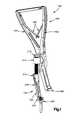
- FIG. 1is a perspective view showing an example medical device for reducing a rod into the head of a screw
- FIG. 2Ais a perspective view showing an example implant holder
- FIGS. 2B-2Care perspective views showing example holding sleeves
- FIG. 2Dis a perspective view showing an example securing foot
- FIG. 2Eis a schematic showing an example stem
- FIG. 2Fis a perspective view showing an example reduction knob
- FIG. 2Gis a schematic showing an example adapter rod
- FIGS. 3A-3Care perspective views showing example implant holders for engaging a screw
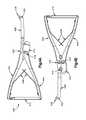
- FIGS. 4A-4Care perspective views showing example handle assemblies
- FIG. 5is a perspective view showing an example rod hook of FIGS. 4A-4C ;
- FIGS. 6A-6Gare perspective views showing example medical devices for reducing a rod into the head of a screw.
- FIG. 7illustrates an operational flow of reducing a rod into the head of a screw, as depicted in FIGS. 6A-6G .
- pedicle screws and rodsare components of rigid stabilization systems, which tend to be intrusive to surrounding tissue and vasculature systems.
- rigid stabilization systemsWhen working with these rigid stabilization systems, surgeons often use instruments to insert the spinal rod into position in the receiving channel of a screw. Surgeons, however, have often encountered considerable difficulty in maneuvering the spinal rod into position in the receiving channel.
- the present disclosureprovides devices and methods for urging spinal rods into the rod receiving channel formed in the spinal implants, which includes the capability to move the spinal rod in more than one direction. The surgeon is also able to use these disclosed devices and methods with only one hand.
- FIG. 1shows an example medical device 100 for reducing a rod into the head of a screw or other bone attachment device.
- the example medical device 100may include an implant holder 120 , a handle assembly 400 , a rod hook 408 , and a guide 410 .
- the implant holder 120includes a holding sleeve 200 with a securing foot 206 pivotally attached to a distal end of the holding sleeve 200 .
- the holding sleeve 200further includes a threaded opening 208 at a proximal end.
- the threaded opening 208is adapted to receive a stem 210 that drives the securing foot 206 between a first position and a second position.
- the implant holder 120also includes a threaded part 216 extending at a predetermined angle from the proximal end 202 of the holding sleeve 200 .
- the threaded part 216is adapted to engage a complementary threaded portion of a reduction knob (not shown in FIG. 1 ).
- the securing foot 206may be adapted to engage the head of a screw 304 .
- the implant holderIn order for the securing foot 206 to fully engage the head of a screw 304 , the implant holder is fully unthreaded so that the securing foot 206 is in the first or “open” position.
- the implant holder 120may then be engaged on the side of the screw head 304 opposite the rod 500 .
- the stem 210may be tightened by one's fingers or an appropriate driver. In order to ensure that the implant holder is securely fit atop of the screw head, the medical professional or other appropriate personnel may lightly pull up on the implant holder 120 .
- the handle assembly 400includes two pivotally attached arms 402 and 404 .
- a rod hook is 408is connected to arm 402 .
- the guide 410is attached to arm 404 .
- the guide 410is adapted to slidably engage the threaded part 216 , such that the rod hook 408 is moveable in a first direction. Movement in a first direction occurs by threaded interaction of the reduction knob with the threaded part 216 . Further, pivotal motion of the arms 402 and 404 causes the rod hook 408 to be moveable in a second direction different than the first direction.
- the handle assembly 400may be placed over the implant holder so that the rod hook 408 is positioned on the same side as the rod 600 .
- the handle assembly 400may be engaged with the implant holder 120 , and the medical professional or other appropriate personnel squeezes arms 402 and 404 of the handle assembly until the rod hook 408 meets the top of the rod 500 .
- the reduction knob 214(not shown) may then be threaded onto the proximal end of the implant holder 120 .
- the reduction knob 214may then be further advanced clockwise to achieve advancement of the rod hook 408 in the first direction.
- the arms 402 and 404 of the handle assemblymay be squeezed to advance the rod hook 408 in a second direction. Advancement in the first and/or second direction may continue until the rod 500 engages the bottom of the rod slot in the head of the screw 304 .
- a locking cap(not shown) may be introduced and tightened.
- the implant holder 120 , handle assembly 400 , rod hook 408 , and guide 410may then be removed by loosening the stem 210 on the implant holder to disengage the securing foot 206 from the head of the screw 304 .
- the example medical device 100may provide reduction of a rod into the head of a screw when the rod is out of alignment in up to two different planes during spinal surgery.
- This medical device 100may be used in the posterior thoracic and lumbar spine region for degenerative and deformity correction.
- the implant holder 120includes a holding sleeve 200 having a proximal end 202 and a distal end 204 .
- Example holding sleeves 200are shown in FIGS. 2B and 2C .
- the holding sleeve 200 and securing foot 206may be attached to a screw.
- the securing foot 206provides for a secure fit, as well as a fit that does not hinder a medical professional's access to all the desired features used on the screw. For example, once a rod is reduced into the head of the screw, the medical professional must be able to introduce some locking mechanism, including but not limited to a locking screw, to lock the rod and screw together. Because the holding sleeve 200 and securing foot 206 are secured to only one side of the screw, the holding sleeve 200 provides access to the screw for introduction of a locking mechanism, once the rod is reduced into the head of the screw.
- an example holding sleeve 200is shown with the distal end 204 of the holding sleeve 200 as optionally defined on three sides.
- One side of the three sidesmay have a recessed portion 236 .
- the two of the three unrecessed sides 238may include concave areas for engaging a screw.
- a securing foot 206is pivotally attached to the distal end 204 of the holding sleeve 200 .
- An example securing foot 206is shown in FIG. 2D .
- the portion of the securing foot 206 engaging the screwmay have a known geometry 218 .
- This known geometry 218 of the securing foot 206may be complementary to the known geometry of the screw to provide a secure fit between the securing foot 206 and the screw, as well as maximizes the contact area between the securing foot 206 and the screw.
- This known geometry 218may vary to accommodate various screw designs, architecture, and/or other screw embodiments.
- the holding sleeve 200further includes a threaded opening 208 at the proximal end 202 of the holding sleeve 200 .
- the threaded opening 208is adapted to receive a stem 210 that drives the securing foot 206 between a first position and a second position.
- An example stem 210is shown in FIG. 2E .
- the stem 210may include a proximal end 226 and a distal end 224 .
- the distal end 224 of the stem 210may optionally include a spherical shape 228 and a ridge area 230 .
- the shape on the distal end 224 of the stem 210provides for ease of use when a medical professional rotates the stem to engage the securing foot 206 with the head of a screw. Further, the shape on the distal end 224 of the stem 210 provides a uniform shape that does not change the position and/or shape of stem 210 as stem 210 advances.
- the stem 210may optionally provide a securing cap 232 on the proximal end 226 of the stem 210 .
- the superior portion of the securing cap 232may include a recessed portion 220 .
- the recessed portion 220may be adapted to a known geometric shape for insertion of a tightening instrument therein.
- a T25 driver 502(as shown in FIGS. 6E-6F ) may be used as a tightening instrument.
- Other appropriate or relevant tightening instrumentsmay be used.
- the recessed portion 220 of the stem 210may be adapted to any known geometric shape for use with any complementary tightening instrument.
- a portion of the stem 210 proximate to the securing cap 232may define a threaded region 234 for a predetermined distance, as shown in FIG. 2E .
- the predetermined distance of the threaded region 234is less than the length of the stem 210 . This predetermined distance ensures that the male threads exit the female threads in such a way that prevents the user from over-loosening the stem and damaging the instrument.
- the length 235 between the bottom of the securing cap 232 and the distal end 224is predefined to act as a safety stop in order to prevent over-tightening of the stem 210 within the implant holder 120 .
- the implant holder 120further includes a threaded part 216 extending at a predetermined angle 212 from the proximal end 202 of the holding sleeve 200 .
- the predetermined angle 212optionally measures approximately 12°. Access during spinal surgery may be limited, so the angle measurement of 12° allows a medical professional adequate access.
- the threaded part 216is adapted to engage a complementary threaded portion of a reduction knob 214 .
- An example reduction knob 214is shown in FIG. 2F .
- the adapter rod 250may have a proximal end 252 and distal end 254 . Both the proximal end 252 and distal end 254 of the adapter rod 250 may be defined in a known geometry. The distal end 254 may be engaged with the recessed portion 222 of the reduction knob 214 . Any known geometry may be chosen for the distal end 254 or proximal end 252 of the adapter rod 250 , or for the recessed portion 222 of the reduction knob 214 . The adapter rod 250 may be rotated to advance the reduction knob 214 along the threaded part 216 in the first direction.
- the threaded part 216may be defined by a modified square thread measuring approximately 10°.
- a modified square threadmay be used to allow medical professionals more efficiency and ease of use when engaging the complementary threads of the reduction knob 214 and threaded part 216 .
- the reduction knob 214may optionally be comprised of polyether ether ketone (PEEK).
- PEEKpolyether ether ketone
- This implant-grade PEEK materialprovides smooth threaded interaction along stainless steel and other metals.
- Implant-grade PEEK materialalso provides strength with minimized friction.
- the threaded portion 216 of the holding sleeve 200may be coated in diamond-like carbon (DLC) coating or any other surface treatment to minimize friction or wear. DLC coating provides minimized friction on the threaded part 216 , provides long-lasting threads, and protects the threaded part 216 (especially the parallel flat surfaces) as it slides through the guide 410 under extreme torque loads that result from maintaining the position of rod 500 .
- DLC coatingprovides minimized friction on the threaded part 216 , provides long-lasting threads, and protects the threaded part 216 (especially the parallel flat surfaces) as it slides through the guide 410 under extreme torque loads that result from maintaining the position of rod 500 .
- the securing foot 206may have a first position 300 or a second position 302 .
- the first position 300is optionally defined as wherein the threaded regions of the stem 210 and holding sleeve 200 are unthreaded.
- FIG. 3Ashows an example implant holder 120 with the threaded regions of the stem 210 and holding sleeve 200 as unthreaded, and the securing foot 206 is optionally in a disengaged position.
- FIG. 3Billustrates an example screw 304 engaged to a ridge portion 240 .
- the distal end 204 of the holding sleeve 200may include the ridge portion 240 for engaging a screw.
- a medical professionalmay engage a screw with holding sleeve 200 , and the ridge portion 240 may provide guidance to the medical professional to know when the holding sleeve 200 is seated atop the screw 304 .
- the securing foot 206may also be defined as in a second position 302 wherein the stem is rotated therein the threaded opening of the holding sleeve 200 .
- FIG. 3Can example implant holder is shown with the threaded region 234 of the stem 210 and holding sleeve 200 as engaged. For example, rotation of the stem 210 into the threaded opening 208 of the holding sleeve 200 engages the securing foot 206 to the head of a screw 304 .
- the handle assembly 400includes two pivotally attached arms 402 and 404 .
- a rod hook 408is connected to arm 402 .
- a guide 410is attached to arm 404 .
- the guide 410is adapted to slidably engage a threaded part of the implant holder ( FIG. 2A ), such that the rod hook 408 is pivotally moveable in the second direction when the guide 410 engages the threaded part.
- pivotal motion of the arms 402 and 404causes the rod hook 408 to be moveable in the second direction, which is different than the first direction.
- the first directionmay be defined as substantially parallel along an axis defining the threaded part.
- the second directionmay be defined as substantially parallel along an axis that may be approximated by an arc created by the movement of the rod hook 408 .
- the guide 410may be defined to cease travel of the rod hook 408 and the spinal rod in the second direction once the pivotally attached arms 402 and 404 are fully squeezed together.
- FIG. 5illustrates the rod hook 408 in greater detail. As shown in FIG. 5 , the distal end 418 of the rod hook 408 may include two concave portions 422 for engaging a spinal rod.
- a lever 412may also be provided with locking mechanisms along the length of lever 412 .
- Complementary locking groovesmay be provided on the proximal end of arm 404 to securely lock the handle assembly as the medical professional squeezes pivotally attached arms 402 and 404 . Once at a position to stop, the medical professional can release the squeezing force, and the handle assembly may optionally lock into the latest position. This feature allows the medical professional to maintain a one-handed operation during the spinal surgery.
- springs 406may be provided between arms 402 and 404 to ensure a spring-loaded effect once the lever 412 , if provided, is released from the locked position. When lever 412 is provided, the medical professional may engage and disengage lever 412 as necessary and as appropriate for the particular clinical situation.
- a guide 410is optionally attached to the rod hook 408 with a pivot screw 414 .
- the arms 402 and 404may be attached by screw 424 , as shown in FIG. 4B .
- Arm 402may be attached to rod hook 408 by screw 420 .
- the guide 410may be attached to the rod hook 408 by pivot screw 414 , and the guide 410 may optionally be attached to arm 404 by screw 416 .
- Screws 414 , 416 , 420 , and 424 at the respective connection jointsallow the rod hook 408 to move in the same direction as arms 402 and 404 when arms 402 and 404 are squeezed.
- the medical devicemay include an implant holder, a handle assembly, a rod hook, and a guide.
- the implant holderincludes a holding sleeve 200 , and the holding sleeve 200 has a proximal end 202 and a distal end 204 .
- a securing foot 206is pivotally attached to the distal end 204 of the holding sleeve 200 .
- the holding sleeve 200further includes a threaded opening 208 at the proximal end 202 of the holding sleeve 200 .
- the threaded opening 208is adapted to receive a stem 210 that drives the securing foot 206 between a first position and a second position.
- the implant holderfurther includes a threaded part 216 extending at a predetermined angle 212 from the proximal end 202 of the holding sleeve 200 .
- the threaded part 216is adapted to engage a complementary threaded portion of a reduction knob 214 .
- the handle assembly 400includes two pivotally attached arms 402 and 404 .
- a rod hook 208is connected to arm 402 .
- a guide 410is attached to arm 404 .
- the guide 410is adapted to slidably engage the threaded part 216 , such that the rod hook 408 is moveable in a first direction. Movement in a first direction occurs by threaded interaction of the reduction knob 214 with the threaded part 216 . Movement in the first direction is defined as substantially parallel along an axis defining the threaded part. Further, pivotal motion of the arms 402 and 404 causes the rod hook 408 to be moveable in a second direction different than the first direction, as described above.
- FIGS. 6A-6GExample methods are illustrated by FIGS. 6A-6G and an operational flow chart 700 in FIG. 7 .
- the securing foot 206 and holding sleeve 200may be attached a head of a screw 304 by the engaging stem ( FIG. 6A ; 702 ).
- the rod hook 408may then be attached to the rod 500 ( FIG. 6A ; 704 ).
- the rod 500may include any type of spinal rod.
- the methodfurther includes advancing a securing foot 206 from a first position to a second position to attach the securing foot 206 and holding sleeve 200 to a screw 304 ( FIG. 6A ; 706 ).
- the rod hook 408is moved in the first direction ( FIGS. 6B and 6C ; 708 ), and then moved in the second direction different than the first direction ( FIGS. 6C and 6D ; 710 ).
- the first directionmay be defined as substantially parallel along an axis defining the threaded part of the implant holder.
- the rod hook 408may be moved in the second direction by squeezing two pivotally attached arms 402 and 404 .
- a lever 412may also be provided with locking mechanisms along the length of lever 412 ( FIG. 6E ; 712 ).
- Complementary locking groovesmay be provided on the proximal end of arm 404 to securely lock the handle assembly as the medical professional squeezes pivotally attached arms 402 and 404 . Once at a position to stop, the medical professional can release the squeezing force, and the handle assembly may optionally lock into the latest position. This feature allows the medical professional to maintain a one-handed operation during spinal surgery.
- a guide 410may be adapted to slidably engage the threaded part 216 of the implant holder.
- the rod hook 408is optionally moveable in the first direction by threaded interaction of the reduction knob 214 with the threaded part 216 ( FIG. 6E ; 714 ). Advancement in the first direction may reduce a rod 600 into a screw 304 .
- a locking cap, or any other appropriate locking mechanism,may optionally be introduced to secure the rod 600 to the screw 304 ( FIG. 6F ; 716 ). Further, the securing foot 206 may be advanced from the second position to the first position to detach the securing foot 206 and holding sleeve 200 from the screw 304 ( FIG. 6G ; 718 ).
- advancement in the first directionmay occur prior to advancement in the second direction.
- advancement in the second directionmay occur prior to advancement in the first direction.
- the movement in the first and second directionmay be iterative.
- a medical professionalmay adjust advancements in the various directions based on his expertise and relevant clinical settings.
- the device 100has been described as being secured to the screw 304 by performing a sequence of steps to attach and secure the securing foot 206 to the head of the screw 304 . It is noted that the removal of the device 100 from screw 304 may be performed in a different reverse order than the order by which the device 100 was secured to the screw 304 . As such, the user is enabled to can remove the device from the surgical site much more quickly during use.
Landscapes
- Health & Medical Sciences (AREA)
- Orthopedic Medicine & Surgery (AREA)
- Neurology (AREA)
- Life Sciences & Earth Sciences (AREA)
- Surgery (AREA)
- Heart & Thoracic Surgery (AREA)
- Engineering & Computer Science (AREA)
- Biomedical Technology (AREA)
- Nuclear Medicine, Radiotherapy & Molecular Imaging (AREA)
- Medical Informatics (AREA)
- Molecular Biology (AREA)
- Animal Behavior & Ethology (AREA)
- General Health & Medical Sciences (AREA)
- Public Health (AREA)
- Veterinary Medicine (AREA)
- Surgical Instruments (AREA)
Abstract
Description
Claims (17)
Priority Applications (4)
| Application Number | Priority Date | Filing Date | Title |
|---|---|---|---|
| US13/592,526US9480505B2 (en) | 2012-08-23 | 2012-08-23 | Bi-planar persuader |
| US15/338,661US10376294B2 (en) | 2012-08-23 | 2016-10-31 | Bi-planar persuader |
| US16/538,170US11344340B2 (en) | 2012-08-23 | 2019-08-12 | Bi-planar persuader |
| US17/735,602US12433647B2 (en) | 2012-08-23 | 2022-05-03 | Bi-planar persuader |
Applications Claiming Priority (1)
| Application Number | Priority Date | Filing Date | Title |
|---|---|---|---|
| US13/592,526US9480505B2 (en) | 2012-08-23 | 2012-08-23 | Bi-planar persuader |
Related Child Applications (1)
| Application Number | Title | Priority Date | Filing Date |
|---|---|---|---|
| US15/338,661ContinuationUS10376294B2 (en) | 2012-08-23 | 2016-10-31 | Bi-planar persuader |
Publications (2)
| Publication Number | Publication Date |
|---|---|
| US20140058464A1 US20140058464A1 (en) | 2014-02-27 |
| US9480505B2true US9480505B2 (en) | 2016-11-01 |
Family
ID=50148690
Family Applications (4)
| Application Number | Title | Priority Date | Filing Date |
|---|---|---|---|
| US13/592,526Active2034-06-07US9480505B2 (en) | 2012-08-23 | 2012-08-23 | Bi-planar persuader |
| US15/338,661Active2033-02-19US10376294B2 (en) | 2012-08-23 | 2016-10-31 | Bi-planar persuader |
| US16/538,170Active2032-11-24US11344340B2 (en) | 2012-08-23 | 2019-08-12 | Bi-planar persuader |
| US17/735,602Active2034-06-10US12433647B2 (en) | 2012-08-23 | 2022-05-03 | Bi-planar persuader |
Family Applications After (3)
| Application Number | Title | Priority Date | Filing Date |
|---|---|---|---|
| US15/338,661Active2033-02-19US10376294B2 (en) | 2012-08-23 | 2016-10-31 | Bi-planar persuader |
| US16/538,170Active2032-11-24US11344340B2 (en) | 2012-08-23 | 2019-08-12 | Bi-planar persuader |
| US17/735,602Active2034-06-10US12433647B2 (en) | 2012-08-23 | 2022-05-03 | Bi-planar persuader |
Country Status (1)
| Country | Link |
|---|---|
| US (4) | US9480505B2 (en) |
Cited By (7)
| Publication number | Priority date | Publication date | Assignee | Title |
|---|---|---|---|---|
| US20160143668A1 (en)* | 2014-11-24 | 2016-05-26 | Aesculap Ag | Pedicle screw system and spinal stabilization system |
| US20170065306A1 (en)* | 2004-02-17 | 2017-03-09 | Globus Medical, Inc. | Facet joint replacement instruments and methods |
| US9956003B2 (en)* | 2015-09-18 | 2018-05-01 | Warsaw Orthopedic, Inc | Spinal implant system and methods of use |
| US10194960B1 (en)* | 2015-12-03 | 2019-02-05 | Nuvasive, Inc. | Spinal compression instrument and related methods |
| US11484349B2 (en)* | 2017-02-17 | 2022-11-01 | Warsaw Orthopedic, Inc. | Surgical system and method |
| US20220401135A1 (en)* | 2012-08-23 | 2022-12-22 | DePuy Synthes Products, Inc. | Bi-planar persuader |
| US11553947B2 (en) | 2019-07-16 | 2023-01-17 | Aesculap Implant Systems, Llc | Spinal deformity sequential persuader |
Families Citing this family (9)
| Publication number | Priority date | Publication date | Assignee | Title |
|---|---|---|---|---|
| EP2967555B1 (en)* | 2013-03-13 | 2018-12-26 | Stryker European Holdings I, LLC | Adjustable forceps for osteosynthesis clip |
| US10136927B1 (en) | 2013-03-15 | 2018-11-27 | Nuvasive, Inc. | Rod reduction assemblies and related methods |
| US9486256B1 (en) | 2013-03-15 | 2016-11-08 | Nuvasive, Inc. | Rod reduction assemblies and related methods |
| US9987053B2 (en)* | 2016-03-29 | 2018-06-05 | Stryker European Holdings I, Llc | Surgical instruments and methods |
| US10485590B2 (en) | 2017-01-18 | 2019-11-26 | K2M, Inc. | Rod reducing device |
| US10966762B2 (en) | 2017-12-15 | 2021-04-06 | Medos International Sarl | Unilateral implant holders and related methods |
| US10828072B2 (en)* | 2018-03-28 | 2020-11-10 | Warsaw Orthopedic, Inc. | Surgical instrument and method |
| US11051861B2 (en) | 2018-06-13 | 2021-07-06 | Nuvasive, Inc. | Rod reduction assemblies and related methods |
| EP4240262B1 (en)* | 2020-11-09 | 2024-12-04 | Medos International Sàrl | Biplanar forceps reducers |
Citations (65)
| Publication number | Priority date | Publication date | Assignee | Title |
|---|---|---|---|---|
| US4271836A (en)* | 1976-06-28 | 1981-06-09 | Wyzsza Szkola Inzynierska Im. Jurija Gagarina | Appliance for correction of spinal curvatures |
| US4411259A (en) | 1980-02-04 | 1983-10-25 | Drummond Denis S | Apparatus for engaging a hook assembly to a spinal column |
| US5020519A (en)* | 1990-12-07 | 1991-06-04 | Zimmer, Inc. | Sagittal approximator |
| US5616143A (en)* | 1995-02-06 | 1997-04-01 | Schlapfer; Johannes F. | Surgical forceps |
| US5720751A (en)* | 1996-11-27 | 1998-02-24 | Jackson; Roger P. | Tools for use in seating spinal rods in open ended implants |
| US5863293A (en)* | 1996-10-18 | 1999-01-26 | Spinal Innovations | Spinal implant fixation assembly |
| US5910141A (en)* | 1997-02-12 | 1999-06-08 | Sdgi Holdings, Inc. | Rod introduction apparatus |
| US6015413A (en)* | 1995-06-20 | 2000-01-18 | Orthofix S.R.L. | Device for the extraction of screw-threaded wires particularly for orthopaedic surgical operations |
| US6123707A (en)* | 1999-01-13 | 2000-09-26 | Spinal Concepts, Inc. | Reduction instrument |
| US20030028195A1 (en)* | 2001-07-25 | 2003-02-06 | Stephane Bette | Ancillary for spinal osteosynthesis system and process for implanting a spinal osteosynthesis system using the said ancillary |
| US6551316B1 (en) | 2001-03-02 | 2003-04-22 | Beere Precision Medical Instruments, Inc. | Selective compression and distraction instrument |
| US6648888B1 (en) | 2002-09-06 | 2003-11-18 | Endius Incorporated | Surgical instrument for moving a vertebra |
| EP1374786A2 (en) | 2002-06-04 | 2004-01-02 | Howmedica Osteonics Corp. | Apparatus for securing a spinal rod system |
| US6746449B2 (en)* | 2001-09-12 | 2004-06-08 | Spinal Concepts, Inc. | Spinal rod translation instrument |
| US6790208B2 (en)* | 2000-03-28 | 2004-09-14 | Showa Ika Kohgyo Co., Ltd. | Rod gripper |
| US20040249378A1 (en)* | 2001-10-04 | 2004-12-09 | Saint Martin Pierre Henri | Spinal osteosynthesis assembly comprising the head of an anchoring member and a tool for fixing said head |
| US20040267275A1 (en)* | 2003-06-26 | 2004-12-30 | Cournoyer John R. | Spinal implant holder and rod reduction systems and methods |
| US20050059969A1 (en)* | 2003-09-17 | 2005-03-17 | Depuy Acromed, Inc. | Rod approximator |
| US20060009775A1 (en)* | 2004-07-06 | 2006-01-12 | Brian Dec | Spinal rod insertion instrument |
| US20060025768A1 (en)* | 2003-07-03 | 2006-02-02 | Andy Iott | Top loading spinal fixation device and instruments for loading and handling the same |
| US7004947B2 (en) | 2002-06-24 | 2006-02-28 | Endius Incorporated | Surgical instrument for moving vertebrae |
| US20060111730A1 (en)* | 2004-11-23 | 2006-05-25 | Medical Innovators, Inc. | Deformity reduction instrument and method |
| US20060293692A1 (en)* | 2005-06-02 | 2006-12-28 | Whipple Dale E | Instruments and methods for manipulating a spinal fixation element |
| US20070161998A1 (en)* | 2005-10-28 | 2007-07-12 | Dale Whipple | Instruments and Methods For Manipulating A Spinal Rod |
| US20070162009A1 (en)* | 2005-03-04 | 2007-07-12 | Chao Nam T | Instruments and methods for manipulating vertebra |
| US20070270868A1 (en)* | 2006-04-24 | 2007-11-22 | Sdgi Holdings, Inc. | Cam based reduction instrument |
| US20070270869A1 (en)* | 2006-04-25 | 2007-11-22 | Young John S | Surgical instrumentation for rod reduction |
| US20070270867A1 (en)* | 2006-04-11 | 2007-11-22 | Sdgi Holdings, Inc. | Multi-directional rod reducer instrument and method |
| US20080154277A1 (en)* | 2004-10-26 | 2008-06-26 | Scott Machalk | Tool apparatus for locking a spinal rod in an anchoring device therefor |
| US20080195155A1 (en)* | 2007-02-12 | 2008-08-14 | Jeffrey Hoffman | Locking instrument for implantable fixation device |
| US20080221626A1 (en) | 2006-09-25 | 2008-09-11 | Stryker Spine | Force limiting persuader-reducer |
| US20080228233A1 (en)* | 2007-02-12 | 2008-09-18 | Jeffrey Hoffman | Instrument for manipulating spinal implant system |
| US7462182B2 (en)* | 2004-08-10 | 2008-12-09 | Warsaw Orthopedic, Inc. | Reducing instrument for spinal surgery |
| US20090018593A1 (en)* | 2007-07-13 | 2009-01-15 | Michael Barrus | Rod reduction device and method of use |
| US7572281B2 (en)* | 2004-08-06 | 2009-08-11 | Depuy Spine, Inc. | Instrument for guiding a rod into an implant in a spinal fixation system |
| US20090228055A1 (en) | 2004-09-24 | 2009-09-10 | Jackson Roger P | Spinal fixation tool set and method for rod reduction and fastener insertion |
| US20090228054A1 (en) | 2008-01-29 | 2009-09-10 | Jeffrey Hoffman | Rod Locking Instrument |
| US20090259262A1 (en) | 2008-04-15 | 2009-10-15 | Warsaw Orthopedic, Inc. | Surgical tool |
| US7611517B2 (en) | 2004-02-27 | 2009-11-03 | Warsaw Orthopedic, Inc. | Rod reducer |
| US20090281582A1 (en) | 2008-05-08 | 2009-11-12 | Raul Villa | Instrument for the reduction of a rod into position in a pedicle screw |
| US7625376B2 (en)* | 2005-01-26 | 2009-12-01 | Warsaw Orthopedic, Inc. | Reducing instrument for spinal surgery |
| US20100004695A1 (en) | 2008-07-07 | 2010-01-07 | Depuy Spine, Inc. | System and method for manipulating a spinal construct |
| US20100030283A1 (en) | 2008-07-31 | 2010-02-04 | Zimmer Spine Austin, Inc. | Surgical instrument with integrated compression and distraction mechanisms |
| US20100069972A1 (en) | 2004-12-02 | 2010-03-18 | Zimmer Spine, Inc. | Instruments and methods for adjusting separation distance of vertebral bodies with a minimally invasive spinal stabilization procedure |
| US7686814B2 (en) | 2004-07-06 | 2010-03-30 | Warsaw Orthopedic, Inc. | Systems and methods for compressing and distracting vertebrae of the spinal column |
| US20100121386A1 (en) | 2008-11-05 | 2010-05-13 | Warsaw Orthopedic, Inc. | Progressive Reduction Instrument for Reduction of a Vertebral Rod and Method of Use |
| US20100121385A1 (en) | 2008-11-10 | 2010-05-13 | Spinal Elements, Inc. | Rod reducer instrument for spinal surgery |
| US7758584B2 (en)* | 2006-04-11 | 2010-07-20 | Synthes Usa, Llc | Minimally invasive fixation system |
| US20100185242A1 (en) | 2009-01-22 | 2010-07-22 | David Barry | Rod Coercer |
| US20100185248A1 (en) | 2009-01-22 | 2010-07-22 | David Barry | Rod Coercer |
| US7776074B2 (en)* | 2005-06-08 | 2010-08-17 | Robert S. Bray, Jr. | Procedure for aligning and stabilizing bone elements |
| US20100228302A1 (en) | 2009-03-04 | 2010-09-09 | Aesculap Implant Systems, Inc. | Spinal rod manipulator instrument |
| US7799031B2 (en)* | 2005-02-09 | 2010-09-21 | Warsaw Orthopedic, Inc. | Reducing instrument for spinal surgery |
| US7824411B2 (en)* | 2003-12-17 | 2010-11-02 | Depuy Spine, Inc. | Instruments and methods for bone anchor engagement and spinal rod reduction |
| US7842044B2 (en)* | 2003-12-17 | 2010-11-30 | Depuy Spine, Inc. | Instruments and methods for bone anchor engagement and spinal rod reduction |
| US7887541B2 (en)* | 2007-07-26 | 2011-02-15 | Depuy Spine, Inc. | Spinal rod reduction instruments and methods for use |
| US7922749B2 (en)* | 2006-04-14 | 2011-04-12 | Warsaw Orthopedic, Inc. | Reducing device |
| US20110118791A1 (en)* | 2008-06-11 | 2011-05-19 | K2M, Inc. | Rod reduction device |
| US7988698B2 (en)* | 2003-01-28 | 2011-08-02 | Depuy Spine, Inc. | Spinal rod approximator |
| US8221474B2 (en)* | 2006-02-09 | 2012-07-17 | Warsaw Orthopedic, Inc. | Spinal derotation instruments and methods |
| US20130018419A1 (en)* | 2011-07-13 | 2013-01-17 | Warsaw Orthopedic, Inc. | Spinal rod system and method |
| USRE44296E1 (en)* | 2001-07-03 | 2013-06-11 | Warsaw Orthopedic, Inc. | Rod reducer instruments and methods |
| US8460300B2 (en)* | 2007-06-12 | 2013-06-11 | Zimmer Spine, Inc. | Instrumentation and associated techniques for minimally invasive vertebral rod installation |
| US8491588B2 (en)* | 2011-06-13 | 2013-07-23 | Warsaw Orthopedic, Inc. | Surgical instrument for securing a spinal rod |
| US8617165B2 (en)* | 2010-09-01 | 2013-12-31 | Globus Medical, Inc. | Rod reducing instrument and methods of use thereof |
Family Cites Families (18)
| Publication number | Priority date | Publication date | Assignee | Title |
|---|---|---|---|---|
| US20060089651A1 (en)* | 2004-10-26 | 2006-04-27 | Trudeau Jeffrey L | Apparatus and method for anchoring a surgical rod |
| US8603094B2 (en)* | 2010-07-26 | 2013-12-10 | Spinal Usa, Inc. | Minimally invasive surgical tower access devices and related methods |
| WO2012034005A2 (en)* | 2010-09-09 | 2012-03-15 | Synthes Usa, Llc | Vertebral adjustment systems for spine alignment |
| EP2460483B1 (en)* | 2010-12-03 | 2013-06-26 | Zimmer Spine | Surgical instrument |
| US8764756B2 (en)* | 2011-02-22 | 2014-07-01 | K2M, Inc. | Single action anti-torque rod reducer |
| US20120277808A1 (en)* | 2011-04-26 | 2012-11-01 | Warsaw Orthopedic, Inc. | Instrument and method for reducing elongate connecting elements |
| US20130066385A1 (en)* | 2011-09-14 | 2013-03-14 | Warsaw Orthopedic, Inc. | Connecting element reduction instrument and methods for using same |
| US9480505B2 (en)* | 2012-08-23 | 2016-11-01 | DePuy Synthes Products, Inc. | Bi-planar persuader |
| US10136927B1 (en)* | 2013-03-15 | 2018-11-27 | Nuvasive, Inc. | Rod reduction assemblies and related methods |
| US10772662B2 (en)* | 2014-10-23 | 2020-09-15 | Warsaw Orthopedic, Inc. | Surgical instrument and method |
| US9757167B2 (en)* | 2015-03-11 | 2017-09-12 | K2M, Inc. | Inserter and method for securing an implant to a spinal process with a flexible fastening system |
| US10568667B2 (en)* | 2016-07-13 | 2020-02-25 | Medos International Sàrl | Bone anchor assemblies and related instrumentation |
| JP7218360B2 (en)* | 2017-09-22 | 2023-02-06 | メドス・インターナショナル・エスエイアールエル | patient-worn surgical support |
| US10966762B2 (en)* | 2017-12-15 | 2021-04-06 | Medos International Sarl | Unilateral implant holders and related methods |
| US11406431B1 (en)* | 2021-05-10 | 2022-08-09 | Warsaw Orthopedic, Inc. | Systems and methods of use and modular instruments with a lateral reducer |
| US20220395302A1 (en)* | 2021-06-11 | 2022-12-15 | ZachMed LLC | Methods and systems for correcting or ameliorating spinal curvature deformities |
| WO2023081425A1 (en)* | 2021-11-05 | 2023-05-11 | Astura Medical Inc. | Lateral rod reducer |
| US20240081876A1 (en)* | 2022-09-13 | 2024-03-14 | Medos International Sarl | Surgical implant instruments and methods of use |
- 2012
- 2012-08-23USUS13/592,526patent/US9480505B2/enactiveActive
- 2016
- 2016-10-31USUS15/338,661patent/US10376294B2/enactiveActive
- 2019
- 2019-08-12USUS16/538,170patent/US11344340B2/enactiveActive
- 2022
- 2022-05-03USUS17/735,602patent/US12433647B2/enactiveActive
Patent Citations (99)
| Publication number | Priority date | Publication date | Assignee | Title |
|---|---|---|---|---|
| US4271836A (en)* | 1976-06-28 | 1981-06-09 | Wyzsza Szkola Inzynierska Im. Jurija Gagarina | Appliance for correction of spinal curvatures |
| US4411259A (en) | 1980-02-04 | 1983-10-25 | Drummond Denis S | Apparatus for engaging a hook assembly to a spinal column |
| US5020519A (en)* | 1990-12-07 | 1991-06-04 | Zimmer, Inc. | Sagittal approximator |
| US5616143A (en)* | 1995-02-06 | 1997-04-01 | Schlapfer; Johannes F. | Surgical forceps |
| US6015413A (en)* | 1995-06-20 | 2000-01-18 | Orthofix S.R.L. | Device for the extraction of screw-threaded wires particularly for orthopaedic surgical operations |
| US5863293A (en)* | 1996-10-18 | 1999-01-26 | Spinal Innovations | Spinal implant fixation assembly |
| US5720751A (en)* | 1996-11-27 | 1998-02-24 | Jackson; Roger P. | Tools for use in seating spinal rods in open ended implants |
| US5910141A (en)* | 1997-02-12 | 1999-06-08 | Sdgi Holdings, Inc. | Rod introduction apparatus |
| USRE43526E1 (en)* | 1997-02-12 | 2012-07-17 | Warsaw Orthopedic, Inc. | Rod introduction apparatus |
| US6123707A (en)* | 1999-01-13 | 2000-09-26 | Spinal Concepts, Inc. | Reduction instrument |
| US6790208B2 (en)* | 2000-03-28 | 2004-09-14 | Showa Ika Kohgyo Co., Ltd. | Rod gripper |
| US6551316B1 (en) | 2001-03-02 | 2003-04-22 | Beere Precision Medical Instruments, Inc. | Selective compression and distraction instrument |
| USRE44813E1 (en)* | 2001-07-03 | 2014-03-18 | Warsaw Orthopedic, Inc. | Rod reducer instruments and methods |
| USRE44296E1 (en)* | 2001-07-03 | 2013-06-11 | Warsaw Orthopedic, Inc. | Rod reducer instruments and methods |
| US6726692B2 (en)* | 2001-07-25 | 2004-04-27 | Spinevision | Ancillary for spinal osteosynthesis system and process for implanting a spinal osteosynthesis system using the said ancillary |
| US20030028195A1 (en)* | 2001-07-25 | 2003-02-06 | Stephane Bette | Ancillary for spinal osteosynthesis system and process for implanting a spinal osteosynthesis system using the said ancillary |
| US6746449B2 (en)* | 2001-09-12 | 2004-06-08 | Spinal Concepts, Inc. | Spinal rod translation instrument |
| US7090679B2 (en)* | 2001-10-04 | 2006-08-15 | Pierre Henri Saint-Martin | Spinal osteosynthesis assembly comprising the head of an anchoring member and a tool for fixing said head |
| US20040249378A1 (en)* | 2001-10-04 | 2004-12-09 | Saint Martin Pierre Henri | Spinal osteosynthesis assembly comprising the head of an anchoring member and a tool for fixing said head |
| EP1374786A2 (en) | 2002-06-04 | 2004-01-02 | Howmedica Osteonics Corp. | Apparatus for securing a spinal rod system |
| US20080004629A1 (en) | 2002-06-04 | 2008-01-03 | Howmedica Osteonics Corp. | Apparatus for securing a spinal rod system |
| US7278995B2 (en) | 2002-06-04 | 2007-10-09 | Howmedica Osteonics Corp. | Apparatus for securing a spinal rod system |
| US7004947B2 (en) | 2002-06-24 | 2006-02-28 | Endius Incorporated | Surgical instrument for moving vertebrae |
| US7618444B2 (en) | 2002-09-06 | 2009-11-17 | Zimmer Spine, Inc. | Surgical instrument for moving a vertebra |
| US6648888B1 (en) | 2002-09-06 | 2003-11-18 | Endius Incorporated | Surgical instrument for moving a vertebra |
| US8636776B2 (en)* | 2003-01-28 | 2014-01-28 | Depuy Spine, Inc. | Spinal rod approximator |
| US7988698B2 (en)* | 2003-01-28 | 2011-08-02 | Depuy Spine, Inc. | Spinal rod approximator |
| US20040267275A1 (en)* | 2003-06-26 | 2004-12-30 | Cournoyer John R. | Spinal implant holder and rod reduction systems and methods |
| US20060025768A1 (en)* | 2003-07-03 | 2006-02-02 | Andy Iott | Top loading spinal fixation device and instruments for loading and handling the same |
| US20050059969A1 (en)* | 2003-09-17 | 2005-03-17 | Depuy Acromed, Inc. | Rod approximator |
| US20110093022A1 (en)* | 2003-12-17 | 2011-04-21 | Runco Thomas J | Instruments and Methods for Bone Anchor Engagement and Spinal Rod Reduction |
| US7842044B2 (en)* | 2003-12-17 | 2010-11-30 | Depuy Spine, Inc. | Instruments and methods for bone anchor engagement and spinal rod reduction |
| US20130317558A1 (en)* | 2003-12-17 | 2013-11-28 | Michael Varieur | Instruments and Methods for Bone Anchor Engagement and Spinal Rod Reduction |
| US7824411B2 (en)* | 2003-12-17 | 2010-11-02 | Depuy Spine, Inc. | Instruments and methods for bone anchor engagement and spinal rod reduction |
| US7611517B2 (en) | 2004-02-27 | 2009-11-03 | Warsaw Orthopedic, Inc. | Rod reducer |
| US7686814B2 (en) | 2004-07-06 | 2010-03-30 | Warsaw Orthopedic, Inc. | Systems and methods for compressing and distracting vertebrae of the spinal column |
| US7371239B2 (en)* | 2004-07-06 | 2008-05-13 | Synthes (U.S.A.) | Spinal rod insertion instrument |
| US20060009775A1 (en)* | 2004-07-06 | 2006-01-12 | Brian Dec | Spinal rod insertion instrument |
| US7572281B2 (en)* | 2004-08-06 | 2009-08-11 | Depuy Spine, Inc. | Instrument for guiding a rod into an implant in a spinal fixation system |
| US7462182B2 (en)* | 2004-08-10 | 2008-12-09 | Warsaw Orthopedic, Inc. | Reducing instrument for spinal surgery |
| US20090228055A1 (en) | 2004-09-24 | 2009-09-10 | Jackson Roger P | Spinal fixation tool set and method for rod reduction and fastener insertion |
| US20080154277A1 (en)* | 2004-10-26 | 2008-06-26 | Scott Machalk | Tool apparatus for locking a spinal rod in an anchoring device therefor |
| US20060111730A1 (en)* | 2004-11-23 | 2006-05-25 | Medical Innovators, Inc. | Deformity reduction instrument and method |
| US20100069972A1 (en) | 2004-12-02 | 2010-03-18 | Zimmer Spine, Inc. | Instruments and methods for adjusting separation distance of vertebral bodies with a minimally invasive spinal stabilization procedure |
| US7811288B2 (en) | 2004-12-02 | 2010-10-12 | Zimmer Spine, Inc. | Instruments and methods for adjusting separation distance of vertebral bodies with a minimally invasive spinal stabilization procedure |
| US20100280560A1 (en) | 2005-01-26 | 2010-11-04 | Warsaw Orthopedic, Inc. | Reducing Instrument for Spinal Surgery |
| US8105329B2 (en)* | 2005-01-26 | 2012-01-31 | Warsaw Orthopedic, Inc. | Reducing instrument for spinal surgery |
| US7744598B2 (en) | 2005-01-26 | 2010-06-29 | Warsaw Orthopedic, Inc. | Reducing instrument for spinal surgery |
| US7625376B2 (en)* | 2005-01-26 | 2009-12-01 | Warsaw Orthopedic, Inc. | Reducing instrument for spinal surgery |
| US20110245884A9 (en) | 2005-01-26 | 2011-10-06 | Warsaw Orthopedic, Inc. | Reducing Instrument for Spinal Surgery |
| US20110054549A1 (en) | 2005-02-09 | 2011-03-03 | Miller Keith E | Reducing instrument for spinal surgery |
| US7799031B2 (en)* | 2005-02-09 | 2010-09-21 | Warsaw Orthopedic, Inc. | Reducing instrument for spinal surgery |
| US8246625B2 (en)* | 2005-02-09 | 2012-08-21 | Warsaw Orthopedic, Inc. | Reducing instrument for spinal surgery |
| US20070162009A1 (en)* | 2005-03-04 | 2007-07-12 | Chao Nam T | Instruments and methods for manipulating vertebra |
| US8647347B2 (en)* | 2005-06-02 | 2014-02-11 | DePuy Synthes Products, LLC | Instruments and methods for manipulating a spinal fixation element |
| US20060293692A1 (en)* | 2005-06-02 | 2006-12-28 | Whipple Dale E | Instruments and methods for manipulating a spinal fixation element |
| US20070260261A1 (en)* | 2005-06-02 | 2007-11-08 | Depuy Spine, Inc. | Instruments and methods for manipulating a spinal fixation element |
| US8216241B2 (en)* | 2005-06-02 | 2012-07-10 | Depuy Spine, Inc. | Instruments and methods for manipulating a spinal fixation element |
| US7776074B2 (en)* | 2005-06-08 | 2010-08-17 | Robert S. Bray, Jr. | Procedure for aligning and stabilizing bone elements |
| US20070161998A1 (en)* | 2005-10-28 | 2007-07-12 | Dale Whipple | Instruments and Methods For Manipulating A Spinal Rod |
| US8221474B2 (en)* | 2006-02-09 | 2012-07-17 | Warsaw Orthopedic, Inc. | Spinal derotation instruments and methods |
| US20110172723A1 (en) | 2006-04-11 | 2011-07-14 | Warsaw Orthopedic, Inc. | Multi-directional rod reducer instrument and method |
| US7927334B2 (en)* | 2006-04-11 | 2011-04-19 | Warsaw Orthopedic, Inc. | Multi-directional rod reducer instrument and method |
| US8556903B2 (en)* | 2006-04-11 | 2013-10-15 | Warsaw Orthopedic, Inc. | Multi-directional rod reducer instrument and method |
| US20070270867A1 (en)* | 2006-04-11 | 2007-11-22 | Sdgi Holdings, Inc. | Multi-directional rod reducer instrument and method |
| US7758584B2 (en)* | 2006-04-11 | 2010-07-20 | Synthes Usa, Llc | Minimally invasive fixation system |
| US7922749B2 (en)* | 2006-04-14 | 2011-04-12 | Warsaw Orthopedic, Inc. | Reducing device |
| US20070270868A1 (en)* | 2006-04-24 | 2007-11-22 | Sdgi Holdings, Inc. | Cam based reduction instrument |
| US7722617B2 (en)* | 2006-04-25 | 2010-05-25 | Warsaw Orthopedic, Inc. | Surgical instrumentation for rod reduction |
| US20070270869A1 (en)* | 2006-04-25 | 2007-11-22 | Young John S | Surgical instrumentation for rod reduction |
| US20080221626A1 (en) | 2006-09-25 | 2008-09-11 | Stryker Spine | Force limiting persuader-reducer |
| US20080195155A1 (en)* | 2007-02-12 | 2008-08-14 | Jeffrey Hoffman | Locking instrument for implantable fixation device |
| US20080228233A1 (en)* | 2007-02-12 | 2008-09-18 | Jeffrey Hoffman | Instrument for manipulating spinal implant system |
| US8460300B2 (en)* | 2007-06-12 | 2013-06-11 | Zimmer Spine, Inc. | Instrumentation and associated techniques for minimally invasive vertebral rod installation |
| US20090018593A1 (en)* | 2007-07-13 | 2009-01-15 | Michael Barrus | Rod reduction device and method of use |
| US7887541B2 (en)* | 2007-07-26 | 2011-02-15 | Depuy Spine, Inc. | Spinal rod reduction instruments and methods for use |
| US8636742B2 (en)* | 2007-07-26 | 2014-01-28 | Depuy Spine, Inc. | Spinal rod reduction instruments and methods for use |
| US20090228054A1 (en) | 2008-01-29 | 2009-09-10 | Jeffrey Hoffman | Rod Locking Instrument |
| US20090259262A1 (en) | 2008-04-15 | 2009-10-15 | Warsaw Orthopedic, Inc. | Surgical tool |
| US20090281582A1 (en) | 2008-05-08 | 2009-11-12 | Raul Villa | Instrument for the reduction of a rod into position in a pedicle screw |
| US20130046344A1 (en)* | 2008-06-11 | 2013-02-21 | K2M, Inc. | Rod reduction device |
| US20110118791A1 (en)* | 2008-06-11 | 2011-05-19 | K2M, Inc. | Rod reduction device |
| US8308729B2 (en)* | 2008-06-11 | 2012-11-13 | K2M, Inc. | Rod reduction device |
| US20100004695A1 (en) | 2008-07-07 | 2010-01-07 | Depuy Spine, Inc. | System and method for manipulating a spinal construct |
| US20100030283A1 (en) | 2008-07-31 | 2010-02-04 | Zimmer Spine Austin, Inc. | Surgical instrument with integrated compression and distraction mechanisms |
| US20100121386A1 (en) | 2008-11-05 | 2010-05-13 | Warsaw Orthopedic, Inc. | Progressive Reduction Instrument for Reduction of a Vertebral Rod and Method of Use |
| US8246623B2 (en)* | 2008-11-05 | 2012-08-21 | Warsaw Orthopedic | Progressive reduction instrument for reduction of a vertebral rod and method of use |
| US20100121385A1 (en) | 2008-11-10 | 2010-05-13 | Spinal Elements, Inc. | Rod reducer instrument for spinal surgery |
| US8137357B2 (en)* | 2009-01-22 | 2012-03-20 | Ebi, Llc | Rod coercer |
| US8128629B2 (en)* | 2009-01-22 | 2012-03-06 | Ebi, Llc | Rod coercer |
| US20130261636A1 (en)* | 2009-01-22 | 2013-10-03 | Ebi, Llc | Rod Coercer |
| US8449549B2 (en)* | 2009-01-22 | 2013-05-28 | Ebi, Llc | Rod coercer |
| US20100185242A1 (en) | 2009-01-22 | 2010-07-22 | David Barry | Rod Coercer |
| US20100185248A1 (en) | 2009-01-22 | 2010-07-22 | David Barry | Rod Coercer |
| US8211111B2 (en)* | 2009-03-04 | 2012-07-03 | Aesculap Implant Systems, Llc | Spinal rod manipulator instrument |
| US20100228302A1 (en) | 2009-03-04 | 2010-09-09 | Aesculap Implant Systems, Inc. | Spinal rod manipulator instrument |
| US8617165B2 (en)* | 2010-09-01 | 2013-12-31 | Globus Medical, Inc. | Rod reducing instrument and methods of use thereof |
| US8491588B2 (en)* | 2011-06-13 | 2013-07-23 | Warsaw Orthopedic, Inc. | Surgical instrument for securing a spinal rod |
| US20130018419A1 (en)* | 2011-07-13 | 2013-01-17 | Warsaw Orthopedic, Inc. | Spinal rod system and method |
Cited By (11)
| Publication number | Priority date | Publication date | Assignee | Title |
|---|---|---|---|---|
| US20170065306A1 (en)* | 2004-02-17 | 2017-03-09 | Globus Medical, Inc. | Facet joint replacement instruments and methods |
| US20220401135A1 (en)* | 2012-08-23 | 2022-12-22 | DePuy Synthes Products, Inc. | Bi-planar persuader |
| US12433647B2 (en)* | 2012-08-23 | 2025-10-07 | DePuy Synthes Products, Inc. | Bi-planar persuader |
| US20160143668A1 (en)* | 2014-11-24 | 2016-05-26 | Aesculap Ag | Pedicle screw system and spinal stabilization system |
| US9795417B2 (en)* | 2014-11-24 | 2017-10-24 | Aesculap Ag | Pedicle screw system and spinal stabilization system |
| US9956003B2 (en)* | 2015-09-18 | 2018-05-01 | Warsaw Orthopedic, Inc | Spinal implant system and methods of use |
| US10194960B1 (en)* | 2015-12-03 | 2019-02-05 | Nuvasive, Inc. | Spinal compression instrument and related methods |
| US11006983B2 (en) | 2015-12-03 | 2021-05-18 | Nuvasive, Inc. | Spinal compression instrument and related methods |
| US12070252B2 (en) | 2015-12-03 | 2024-08-27 | Nuvasive, Inc. | Spinal compression instrument and related methods |
| US11484349B2 (en)* | 2017-02-17 | 2022-11-01 | Warsaw Orthopedic, Inc. | Surgical system and method |
| US11553947B2 (en) | 2019-07-16 | 2023-01-17 | Aesculap Implant Systems, Llc | Spinal deformity sequential persuader |
Also Published As
| Publication number | Publication date |
|---|---|
| US20220401135A1 (en) | 2022-12-22 |
| US20140058464A1 (en) | 2014-02-27 |
| US11344340B2 (en) | 2022-05-31 |
| US12433647B2 (en) | 2025-10-07 |
| US20200038074A1 (en) | 2020-02-06 |
| US10376294B2 (en) | 2019-08-13 |
| US20170042590A1 (en) | 2017-02-16 |
Similar Documents
| Publication | Publication Date | Title |
|---|---|---|
| US12433647B2 (en) | Bi-planar persuader | |
| US12076060B2 (en) | Derotation apparatus for treating spinal irregularities | |
| US8298275B2 (en) | Direct control spinal implant | |
| US8992536B2 (en) | Coplanar deformity correction system | |
| US20150100098A1 (en) | Rod reducer | |
| EP2878276B1 (en) | System for corrective spinal surgery | |
| US20110257690A1 (en) | Transverse and Sagittal Adjusting Screw | |
| US20150100097A1 (en) | Rod reducer | |
| US10813670B2 (en) | Spinal stabilization system | |
| US10973552B2 (en) | Surgical system for bone screw insertion and rod reduction | |
| US9095378B2 (en) | Spinal stabilization system | |
| US20250017630A1 (en) | Spinal Implant And Methods Of Use Thereof | |
| US20170143385A1 (en) | Spinal rod reduction system | |
| KR20180134861A (en) | Tools to dynamically stabilize and locate intervertebral implants |
Legal Events
| Date | Code | Title | Description |
|---|---|---|---|
| AS | Assignment | Owner name:SYNTHES USA, LLC, PENNSYLVANIA Free format text:ASSIGNMENT OF ASSIGNORS INTEREST;ASSIGNOR:HUTCHENS, CHRISTOPHER;REEL/FRAME:029300/0956 Effective date:20121002 | |
| AS | Assignment | Owner name:HAND INNOVATIONS LLC, FLORIDA Free format text:ASSIGNMENT OF ASSIGNORS INTEREST;ASSIGNOR:DEPUY SPINE, LLC;REEL/FRAME:030359/0001 Effective date:20121230 Owner name:DEPUY SPINE, LLC, MASSACHUSETTS Free format text:ASSIGNMENT OF ASSIGNORS INTEREST;ASSIGNOR:SYNTHES USA, LLC;REEL/FRAME:030358/0945 Effective date:20121230 Owner name:DEPUY SYNTHES PRODUCTS, LLC, MASSACHUSETTS Free format text:CHANGE OF NAME;ASSIGNOR:HAND INNOVATIONS LLC;REEL/FRAME:030359/0036 Effective date:20121231 | |
| AS | Assignment | Owner name:DEPUY SYNTHES PRODUCTS, INC., MASSACHUSETTS Free format text:CHANGE OF NAME;ASSIGNOR:DEPUY SYNTHES PRODUCTS, LLC;REEL/FRAME:035074/0647 Effective date:20141219 | |
| STCF | Information on status: patent grant | Free format text:PATENTED CASE | |
| AS | Assignment | Owner name:HAND INNOVATIONS LLC, FLORIDA Free format text:CORRECTIVE ASSIGNMENT TO CORRECT THE INCORRECT APPL. NO. 13/486,591 PREVIOUSLY RECORDED AT REEL: 030359 FRAME: 0001. ASSIGNOR(S) HEREBY CONFIRMS THE ASSIGNMENT;ASSIGNOR:DEPUY SPINE, LLC;REEL/FRAME:042621/0565 Effective date:20121230 | |
| AS | Assignment | Owner name:DEPUY SPINE, LLC, MASSACHUSETTS Free format text:CORRECTIVE ASSIGNMENT TO CORRECT THE INCORRECT APPLICATION NO. US 13/486,591 PREVIOUSLY RECORDED ON REEL 030358 FRAME 0945. ASSIGNOR(S) HEREBY CONFIRMS THE ASSIGNMENT;ASSIGNOR:SYNTHES USA, LLC;REEL/FRAME:042687/0849 Effective date:20121230 | |
| MAFP | Maintenance fee payment | Free format text:PAYMENT OF MAINTENANCE FEE, 4TH YEAR, LARGE ENTITY (ORIGINAL EVENT CODE: M1551); ENTITY STATUS OF PATENT OWNER: LARGE ENTITY Year of fee payment:4 | |
| MAFP | Maintenance fee payment | Free format text:PAYMENT OF MAINTENANCE FEE, 8TH YEAR, LARGE ENTITY (ORIGINAL EVENT CODE: M1552); ENTITY STATUS OF PATENT OWNER: LARGE ENTITY Year of fee payment:8 |