US9480475B2 - Bone plate suture anchor - Google Patents
Bone plate suture anchorDownload PDFInfo
- Publication number
- US9480475B2 US9480475B2US13/829,171US201313829171AUS9480475B2US 9480475 B2US9480475 B2US 9480475B2US 201313829171 AUS201313829171 AUS 201313829171AUS 9480475 B2US9480475 B2US 9480475B2
- Authority
- US
- United States
- Prior art keywords
- crossbar
- suture anchor
- anchor insert
- sidewall
- bone plate
- Prior art date
- Legal status (The legal status is an assumption and is not a legal conclusion. Google has not performed a legal analysis and makes no representation as to the accuracy of the status listed.)
- Active, expires
Links
- 210000000988bone and boneAnatomy0.000titleclaimsabstractdescription61
- 230000006835compressionEffects0.000claimsdescription4
- 238000007906compressionMethods0.000claimsdescription4
- 208000010392Bone FracturesDiseases0.000description14
- 210000004872soft tissueAnatomy0.000description8
- 238000003780insertionMethods0.000description6
- 230000037431insertionEffects0.000description6
- 238000000926separation methodMethods0.000description6
- 238000000034methodMethods0.000description5
- 210000002435tendonAnatomy0.000description5
- 210000003041ligamentAnatomy0.000description4
- 230000006641stabilisationEffects0.000description4
- 238000011105stabilizationMethods0.000description4
- 238000004891communicationMethods0.000description3
- 238000010276constructionMethods0.000description2
- 239000012634fragmentSubstances0.000description2
- 230000035876healingEffects0.000description2
- 238000004873anchoringMethods0.000description1
- 238000006073displacement reactionMethods0.000description1
- 238000002474experimental methodMethods0.000description1
- 238000010348incorporationMethods0.000description1
- 238000005096rolling processMethods0.000description1
- 210000001519tissueAnatomy0.000description1
Images


Classifications
- A—HUMAN NECESSITIES
- A61—MEDICAL OR VETERINARY SCIENCE; HYGIENE
- A61B—DIAGNOSIS; SURGERY; IDENTIFICATION
- A61B17/00—Surgical instruments, devices or methods
- A61B17/064—Surgical staples, i.e. penetrating the tissue
- A61B17/0642—Surgical staples, i.e. penetrating the tissue for bones, e.g. for osteosynthesis or connecting tendon to bone
- A—HUMAN NECESSITIES
- A61—MEDICAL OR VETERINARY SCIENCE; HYGIENE
- A61B—DIAGNOSIS; SURGERY; IDENTIFICATION
- A61B17/00—Surgical instruments, devices or methods
- A61B17/04—Surgical instruments, devices or methods for suturing wounds; Holders or packages for needles or suture materials
- A61B17/0401—Suture anchors, buttons or pledgets, i.e. means for attaching sutures to bone, cartilage or soft tissue; Instruments for applying or removing suture anchors
- A—HUMAN NECESSITIES
- A61—MEDICAL OR VETERINARY SCIENCE; HYGIENE
- A61B—DIAGNOSIS; SURGERY; IDENTIFICATION
- A61B17/00—Surgical instruments, devices or methods
- A61B17/56—Surgical instruments or methods for treatment of bones or joints; Devices specially adapted therefor
- A61B17/58—Surgical instruments or methods for treatment of bones or joints; Devices specially adapted therefor for osteosynthesis, e.g. bone plates, screws or setting implements
- A61B17/68—Internal fixation devices, including fasteners and spinal fixators, even if a part thereof projects from the skin
- A61B17/84—Fasteners therefor or fasteners being internal fixation devices
- A61B17/842—Flexible wires, bands or straps
- A—HUMAN NECESSITIES
- A61—MEDICAL OR VETERINARY SCIENCE; HYGIENE
- A61B—DIAGNOSIS; SURGERY; IDENTIFICATION
- A61B17/00—Surgical instruments, devices or methods
- A61B17/56—Surgical instruments or methods for treatment of bones or joints; Devices specially adapted therefor
- A61B17/58—Surgical instruments or methods for treatment of bones or joints; Devices specially adapted therefor for osteosynthesis, e.g. bone plates, screws or setting implements
- A61B17/68—Internal fixation devices, including fasteners and spinal fixators, even if a part thereof projects from the skin
- A61B17/80—Cortical plates, i.e. bone plates; Instruments for holding or positioning cortical plates, or for compressing bones attached to cortical plates
- A—HUMAN NECESSITIES
- A61—MEDICAL OR VETERINARY SCIENCE; HYGIENE
- A61B—DIAGNOSIS; SURGERY; IDENTIFICATION
- A61B17/00—Surgical instruments, devices or methods
- A61B17/04—Surgical instruments, devices or methods for suturing wounds; Holders or packages for needles or suture materials
- A61B17/0401—Suture anchors, buttons or pledgets, i.e. means for attaching sutures to bone, cartilage or soft tissue; Instruments for applying or removing suture anchors
- A61B2017/0403—Dowels
- A—HUMAN NECESSITIES
- A61—MEDICAL OR VETERINARY SCIENCE; HYGIENE
- A61B—DIAGNOSIS; SURGERY; IDENTIFICATION
- A61B17/00—Surgical instruments, devices or methods
- A61B17/04—Surgical instruments, devices or methods for suturing wounds; Holders or packages for needles or suture materials
- A61B17/0401—Suture anchors, buttons or pledgets, i.e. means for attaching sutures to bone, cartilage or soft tissue; Instruments for applying or removing suture anchors
- A61B2017/0438—Suture anchors, buttons or pledgets, i.e. means for attaching sutures to bone, cartilage or soft tissue; Instruments for applying or removing suture anchors slotted, i.e. having a longitudinal slot for enhancing their elasticity
- A—HUMAN NECESSITIES
- A61—MEDICAL OR VETERINARY SCIENCE; HYGIENE
- A61B—DIAGNOSIS; SURGERY; IDENTIFICATION
- A61B17/00—Surgical instruments, devices or methods
- A61B17/04—Surgical instruments, devices or methods for suturing wounds; Holders or packages for needles or suture materials
- A61B17/0401—Suture anchors, buttons or pledgets, i.e. means for attaching sutures to bone, cartilage or soft tissue; Instruments for applying or removing suture anchors
- A61B2017/044—Suture anchors, buttons or pledgets, i.e. means for attaching sutures to bone, cartilage or soft tissue; Instruments for applying or removing suture anchors with a threaded shaft, e.g. screws
- A—HUMAN NECESSITIES
- A61—MEDICAL OR VETERINARY SCIENCE; HYGIENE
- A61B—DIAGNOSIS; SURGERY; IDENTIFICATION
- A61B17/00—Surgical instruments, devices or methods
- A61B17/04—Surgical instruments, devices or methods for suturing wounds; Holders or packages for needles or suture materials
- A61B17/0401—Suture anchors, buttons or pledgets, i.e. means for attaching sutures to bone, cartilage or soft tissue; Instruments for applying or removing suture anchors
- A61B2017/0445—Suture anchors, buttons or pledgets, i.e. means for attaching sutures to bone, cartilage or soft tissue; Instruments for applying or removing suture anchors cannulated, e.g. with a longitudinal through-hole for passage of an instrument
- A—HUMAN NECESSITIES
- A61—MEDICAL OR VETERINARY SCIENCE; HYGIENE
- A61B—DIAGNOSIS; SURGERY; IDENTIFICATION
- A61B17/00—Surgical instruments, devices or methods
- A61B17/04—Surgical instruments, devices or methods for suturing wounds; Holders or packages for needles or suture materials
- A61B17/0401—Suture anchors, buttons or pledgets, i.e. means for attaching sutures to bone, cartilage or soft tissue; Instruments for applying or removing suture anchors
- A61B2017/0446—Means for attaching and blocking the suture in the suture anchor
- A61B2017/0448—Additional elements on or within the anchor
- A—HUMAN NECESSITIES
- A61—MEDICAL OR VETERINARY SCIENCE; HYGIENE
- A61B—DIAGNOSIS; SURGERY; IDENTIFICATION
- A61B17/00—Surgical instruments, devices or methods
- A61B17/04—Surgical instruments, devices or methods for suturing wounds; Holders or packages for needles or suture materials
- A61B17/0401—Suture anchors, buttons or pledgets, i.e. means for attaching sutures to bone, cartilage or soft tissue; Instruments for applying or removing suture anchors
- A61B2017/0446—Means for attaching and blocking the suture in the suture anchor
- A61B2017/0458—Longitudinal through hole, e.g. suture blocked by a distal suture knot
Definitions
- Bone fracturesmay take many forms: complete, incomplete, simple, comminuted, closed, or open. Fractures may also be associated with separation of connections between soft tissue and bone. Fractures, with and without soft tissue separation, often require stabilization to promote faster healing and unimpaired function. Stabilization may return function and mobility for the injured area earlier than treatment without stabilization. Fracture fixation and stabilization procedures are generally of two types, internal or external. External fixation methods may include slings, splints, or casts. Internal fixation methods may employ wires, pins and screws, bone plates, and intramedullary nails or rods.
- Fractures treated with bone platesmay be treated by exposing the fracture site and reducing the bone fracture, then placing a plate onto the bone to secure the fracture for healing in the reduced position.
- the fracture and surrounding boneare realigned and positioned in the original bone position or a similar stable position.
- Bone platesmay be used in flexible fracture fixation or rigid fixation. Flexible fixation occurs where the fracture fragments displace in relation to each other when a load is applied across the fracture site.
- Rigid fixation techniquesemploy plates and screws in order to limit displacement of fracture fragments in relation to each other.
- the separationmay take the form of a separation of the soft tissue at the osseous junction or a fracture at a tuberosity. Tuberosities, the bone site for attachment between tendon and bone, may be displaced in a fracture. Ligaments and tendons may be detached from the bone at the fibro-osseous junction, which is the connection between the soft tissue and bone. Where a fracture is associated with a tendon or ligament separation, fixation of the fracture may require anchoring of the tendon or ligament to the bone.
- Suture anchorsare commonly used to anchor soft tissue to bone.
- Suture anchorsare generally implanted into the bone so as to secure one or more sutures extending from a body used to secure the soft tissue by holding the tissue in position to the bone.
- Bone plateshave also been used as a securing element for sutures. The sutures have been secured to the plate by threading the sutures through holes in the plate before the plate is secured to the bone. The use of bone plates to anchor sutures in this manner often limits the suture attachment locations available to a surgeon, particularly after the plate has been attached to the bone.
- FIG. 1is a perspective view of a bone plate with a suture anchor insert constructed in accordance with the inventive concepts disclosed herein.
- FIG. 2is a perspective view of the suture anchor insert constructed in accordance with the inventive concepts disclosed herein.
- FIG. 3is a top plan view of the suture anchor insert of FIG. 2 .
- FIG. 4Ais a sectional view taken along line 4 - 4 of FIG. 3 illustrating a crossbar in an unflexed condition.
- FIG. 4Bis a sectional view of the suture anchor insert of FIG. 4A illustrating the crossbar in a flexed condition.
- FIG. 5is a perspective view of the suture anchor insert of FIG. 2 shown being installed into a bone plate.
- FIG. 6is a perspective view of the suture anchor insert of FIG. 2 shown installed in the bone plate.
- FIG. 7is a sectional view of the suture anchor insert of FIG. 2 shown with a suture captured by the suture anchor insert.
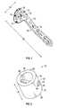
- FIG. 8is a perspective view of another embodiment of a suture anchor insert constructed in accordance with the inventive concepts disclosed herein.
- FIG. 9is a sectional view of the suture anchor insert of FIG. 8 shown inserted into a bone plate.
- FIG. 10is a sectional view of another embodiment of a suture anchor insert constructed in accordance with the inventive concepts disclosed herein.
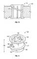
- FIG. 11is a perspective view of another embodiment of a suture anchor insert constructed in accordance with the inventive concepts disclosed herein.
- FIG. 12is a top plan view of the suture anchor insert of FIG. 11 shown inserted into a bone plate.
- FIG. 13is a sectional view taken along line 13 - 13 of FIG. 12 .
- FIG. 1a plurality of suture anchor inserts 10 constructed in accordance with the inventive concepts disclosed herein are shown inserted into a bone plate 12 .
- the plate 12has an upper surface 18 , a lower surface 20 , a length 22 , and a width 24 .
- the plate 12has a plurality of holes 16 formed therein extending through the plate 12 from the upper surface 18 to the lower surface 20 .
- the plurality of holes 16may comprise threaded holes, non-threaded holes, partially threaded holes, tapered holes, and straight holes, for example.
- the bone plate 12shown in FIG.
- the bone plate 12is an example of the bone plate 12 , however, it will be appreciated by one skilled in the art that the bone plate 12 may be provided in varying forms while being in accordance with the inventive concepts disclosed herein.
- the bone plate 12may be substantially rectangular or circular in shape.
- the bone plate 12may employ a “T”, “Y”, or “H” shape.
- the bone plate 12may be provided with holes 16 disposed in a single line, parallel lines, offset from one another, or staggered about the bone plate 12 .
- the bone plate 12may also have sections disposed at an angle to a plane of a remaining section of the bone plate 12 .
- the suture anchor insert 10has a body 14 configured to be slidably inserted into one of the holes 16 of the bone plate 12 .
- the body 14has a proximal end 26 , a distal end 28 , a length 30 extending between the proximal end 26 and the distal end 28 substantially corresponding to a thickness of the plate 12 , and a sidewall 32 extending between the proximal end 26 and the distal end 28 .
- the sidewall 32is provided with at least one plate engaging member 34 ( FIG. 6 ).
- the sidewall 32defines a recess 36 within the body 14 of the suture anchor insert 10 .
- the sidewall 32is further provided with a transverse edge 38 . Opposite the transverse edge 38 , the sidewall 32 is provided with a crossbar 40 .
- the crossbar 40extends inwardly therefrom across the recess 36 such that a free end 42 of the crossbar 40 is normally disposed distally of the transverse edge 38 ( FIG. 4A ).
- the crossbar 40is flexible such that when a distally directed force is applied to the crossbar 40 , the free end 42 of the crossbar 40 is positioned in the recess 36 ( FIG. 4B ) and when a proximally directed force is applied to the crossbar 40 such as by a suture which is looped over the crossbar 40 , the free end 42 of the crossbar 40 engages with the transverse edge 38 to limit proximal motion of the crossbar 40 .
- the sidewall 32 of the body 14may be provided with a crossbar window 44 which is in communication with the recess 36 .
- the crossbar window 44has a proximal side 46 and a distal side 48 where the proximal side 46 of the crossbar window 44 defines the transverse edge 38 .
- the crossbar 40extends across the recess 36 such that the free end 42 of the crossbar 40 is normally disposed in the crossbar window 44 .
- the plate engaging member 34is formed after insertion of the suture anchor insert 10 into the hole 16 of the plate 12 .
- FIG. 5illustrates, in this embodiment, the initial length 22 of the suture anchor insert 10 is greater than the thickness of the plate 12 , such that when initially inserted into the plate 12 , the proximal end 26 and the distal end 28 extend past the upper surface 18 and the lower surface 20 of the plate 12 , respectively.
- the proximal end 26 and distal end 28 of the suture anchor insert 10may be deformed.
- the proximal end 26may be deformed in a distal direction toward the upper surface 18 of the plate 12 until the proximal end 26 contacts the upper surface 18 , forming a first lip 50 extending outwardly at the proximal end 26 and engageable with the upper surface 18 of the plate 12 .
- the distal end 28may be deformed in a proximal direction toward the lower surface 20 of the plate 12 until the distal end 28 contacts the lower surface 20 , forming a second lip 52 extending outwardly at the distal end 28 and engageable with the lower surface 20 of the plate 12 .
- the proximal end 26 and distal end 28may be deformed, for example, by compressing, rolling, splitting, or capping the proximal end 26 and distal end 28 .
- One or more sutures 54may be attached to the suture anchor insert 10 after the suture anchor insert 10 has been inserted into the plate 12 and the first lip 50 and the second lip 52 have been formed on the upper surface 18 and the lower surface 20 , respectively, securing the suture anchor insert 10 in place in the hole 16 .
- the one or more sutures 54may be attached prior to insertion of the suture anchor insert 10 into the plate 12 .
- the one or more sutures 54may be attached to suture anchor insert 10 in any suitable fashion.
- the one or more sutures 54may be positioned about the crossbar 40 with a suture threader which is disclosed in U.S. Publication No. 2009/0088798, which is hereby expressly incorporated herein by reference.
- the suture anchor insert 10may be placed in selected locations on the plate 12 by inserting the suture anchor insert 10 into a selected one of the plurality of holes 16 of the bone plate 12 .
- the plurality of positions available for insertion of the suture anchor insert 10enable placement of one or more sutures 54 according to the needs of the surgeon at the time of placement of the plate 12 , the suture anchor insert 10 , and the sutures 54 . Maintaining the variability of the suture anchor insert 10 , the suture anchor insert 10 may be provided as a kit including the plate 12 and at least one suture anchor insert 10 .
- the suture anchor insert 60has a body 62 and a crossbar 63 .
- the body 62is configured to be slidably inserted into the hole 16 in the bone plate 12 .
- the body 62has a proximal end 68 , a distal end 70 , a length 72 extending between the proximal end 68 and the distal end 70 substantially corresponding to a thickness of the plate 12 , and a sidewall 74 extending between the proximal end 68 and the distal end 70 .
- the body 62 of the suture anchor insert 60is distally tapered from the proximal end 68 toward the distal end 70 to engage a hole 64 having a corresponding distal taper, the body 62 conforming to the contour of the hole 64 .
- the sidewall 74is provided with a plate engaging member 76 extending outwardly therefrom, and a transverse edge 78 .
- the sidewall 74defines a recess 80 within the body 62 of the suture anchor insert 60 .
- the crossbar 63extends inwardly from the sidewall 74 and across the recess 80 such that a free end 84 of the crossbar 63 is normally disposed distally of the transverse edge 78 .
- the crossbar 63is flexible such that when a distally directed force is applied to the crossbar 63 , the free end 84 of the crossbar 63 is positioned in the recess 80 and when a proximally directed force is applied to the crossbar 63 , the free end 84 of the crossbar 63 engages with the transverse edge 78 to limit proximal motion of the crossbar 63 .
- the sidewall 74may be provided with a crossbar window 86 which is in communication with the recess 80 .
- the crossbar window 86has a proximal side 88 and a distal side 90 where the proximal side 88 of the crossbar window 86 defines the transverse edge 78 .
- the crossbar 63extends across the recess 80 such that the free end 84 of the crossbar 63 is normally disposed in the crossbar window 86 .
- the sidewall 74is further provided with a pair of slots 92 .
- the slots 92are formed in a diametrically opposed relationship to one another and extend from the distal end 70 toward the proximal end 68 of the suture anchor insert 60 to enable compression of the body 62 such that the body 62 is moveable between a compressed position, wherein the suture anchor insert 60 is slidable into the hole 16 of the plate 12 , and an expanded position, wherein the suture anchor insert 60 is secured within the hole 16 in the plate 12 .
- the crossbar 63is moveable within the crossbar window 86 without limiting the compression of the body 62 .
- the sidewall 74has been shown to include two slots 92 , it will be appreciated that the number of slots 92 may vary and the slots 92 may be placed at varying positions and orientations relative to one another to facilitate compression of the body 62 .
- the plate engaging members 76is in the form of a first lip 104 extending outwardly at the proximal end 68 of the sidewall 74 and engageable with the upper surface 18 of the plate 12 , and a second lip 108 extending outwardly at the proximal end 68 of the sidewall 74 and engageable with the lower surface 20 of the plate 12 .
- the second lip 108may be curved at the distal end 70 of the suture anchor insert 60 to facilitate slidably inserting the suture anchor insert 60 into the plate 12 .
- the suture anchor insert 60is slidably inserted into the plate 12 by compressing the body 62 near the distal end 70 of the suture anchor insert 60 .
- the suture anchor insert 60is then positioned at the entrance of the hole 16 .
- the suture anchor insert 60is slidably inserted into the hole 16 by a distally directed force exerted on the suture anchor insert 60 .
- the suture anchor insert 60reverts to the expanded position, causing the first lip 104 to engage the upper surface 18 of the plate 12 and the second lip 108 to engage the lower surface 20 of the plate 12 , thereby securing the suture anchor insert 60 within the hole 16 of the plate 12 .
- One or more suturesmay be attached to the suture anchor insert 60 by disposing the one or more sutures about the crossbar 63 .
- the one or more suturesmay be attached to suture anchor insert 60 in any suitable fashion, as previously discussed, such as by use of a suture threader.
- the suture anchor insert 60may be placed in selected locations on the plate 12 by inserting the suture anchor insert 60 into one of the plurality of holes 16 of the plate 12 .
- the plurality of positions available for insertion of the suture anchor insert 60enable placement of sutures according to the needs of the surgeon at the time of placement of the sutures. Maintaining the variability of the suture anchor insert 60 , the suture anchor insert 60 may be provided as a kit including the plate 12 and at least one suture anchor insert 60 .
- FIG. 10Shown in FIG. 10 is another embodiment of a suture anchor insert 112 .
- the suture anchor insert 112is substantially similar in construction and function to the suture anchor insert 60 , except that suture anchor insert 112 has a body 114 with no distal taper. Thus, the body 114 is inserted into a hole 116 of a plate 118 which has a straight configuration.
- FIGS. 11-13illustrate another embodiment of a suture anchor insert 120 constructed in accordance with the inventive concepts disclosed herein.
- the suture anchor insert 120has a body 122 and a crossbar 124 .
- the body 122is configured to be inserted into a hole 126 in a bone plate 128 .
- the bone plate 128has an upper surface 130 , a lower surface 132 , a length 134 , and a width 136 .
- the plate 128has a plurality of holes 126 formed therein extending through the plate 128 from the upper surface 130 to the lower surface 132 .
- the plurality of holes 126may comprise threaded holes, non-threaded holes, partially threaded holes, tapered holes, and straight holes, for example. As shown in FIG.
- one or more of the plurality of holes 126are threaded holes, having a threaded portion 138 extending from the upper surface 130 toward the lower surface 132 and ending medially between the upper surface 130 and the lower surface 132 , and an open portion 140 extending from the ending of the threaded portion 138 medially between the upper surface 130 and the lower surface 132 and toward the lower surface 132 .
- the body 122is configured to be slidably inserted into one of the holes 126 of the bone plate 128 .
- the body 122has a proximal end 142 , a distal end 144 , a length 146 extending between the proximal end 142 and the distal end 144 substantially corresponding to a thickness of the plate 128 , and a sidewall 148 extending between the proximal end 142 and the distal end 144 .
- the sidewall 148is provided with plate engaging members 147 extending outwardly therefrom, and a transverse edge 150 .
- the sidewall 148defines a recess 154 within the body 122 of the suture anchor insert 120 .
- the crossbar 124extends inwardly from the sidewall 148 across the recess 154 such that a free end 152 of the crossbar 124 is normally disposed distally of the transverse edge 150 .
- the crossbar 124is flexible such that when a distally directed force is applied to the crossbar 124 , the free end 152 of the crossbar 124 is positioned in the recess 154 and when a proximally directed force is applied to the crossbar 124 , the free end 152 of the crossbar 124 engages with the transverse edge 150 to limit proximal motion of the crossbar 124 .
- the sidewall 148may be provided with a crossbar window 156 which is in communication with the recess 154 .
- the crossbar window 156has a proximal side 158 and a distal side 160 where the proximal side 158 of the crossbar window 156 defines the transverse edge 150 .
- the crossbar 124extends across the recess 154 such that the free end 152 of the crossbar 124 is normally disposed in the crossbar window 156 .
- the plate engaging members 147are in the form of a lip 162 extending outwardly at the proximal end 142 of the sidewall 148 and a helical thread 164 .
- the proximal end 142 of the suture anchor insert 120is configured to engage a driver to rotatably insert the suture anchor insert 120 into the plate 128 .
- the suture anchor insert 120is slidably inserted into the plate 128 by positioning the suture anchor insert 120 as the entrance of the hole 126 .
- a driverengages the suture anchor insert 120 at the proximal end 142 and the suture anchor insert 120 is slidably inserted into the hole 126 by applying a torsional force to the driver, causing the helical thread 164 of the suture anchor insert 120 to engage a threaded portion 166 of the hole 126 .
- the suture anchor insert 120is thus slidably inserted into the hole 126 such that the helical thread 164 is slidably inserted past the threaded portion 166 of the hole 126 .
- One or more suturesmay be attached to the suture anchor insert 120 , as discussed above, by disposing the one or more sutures about the crossbar 124 .
- the one or more suturesmay be attached to suture anchor insert 120 in any suitable fashion, such as by using a suture threader, as discussed above.
- the suture anchor insert 120may be placed in differing locations on the plate 128 by slidably inserting the suture anchor insert 120 into one of the plurality of holes 126 .
- the plurality of positions available for insertion of the suture anchor insert 120enable placement of one or more sutures according to the needs of the surgeon at the time of the sutures. Maintaining the variability of the suture anchor insert 120 , the suture anchor insert 120 may be provided as a kit including the plate 128 and at least one suture anchor insert 120 .
- Connecting a suture to a bone plate 12is accomplished as follows. First a bone and soft tissue in need of repair are accessed using any suitable instrument, such as a scalpel, forceps, retractor, or combinations thereof. The plate 12 is secured to a bone using any suitable method, such as bone screws installed through one or more of the plurality of holes 16 . At least one suture anchor insert 10 is slidably inserted into one of the holes 16 in the plate 12 . At least one suture is disposed about the crossbar 40 of the suture anchor insert 10 .
- suture anchor insert 10the suture anchor insert 10 is inserted prior to securing the plate 12 to the bone enabling the distal end 28 of the suture anchor insert 10 to be deformed to form the second lip 52 , engaging the lower surface 20 of the plate 12 .
- the embodiments of suture anchor insert 60 and suture anchor insert 120may be inserted into the plate 12 and plate 128 , respectively, prior or subsequent to securing the plate 12 and plate 128 , respectively, to the bone.
- the one or more sutures 54may be attached to the suture anchor insert 10 prior to insertion into the plate. Otherwise, the configuration of the suture anchor insert 10 enables the one or more sutures 54 to be attached to the suture anchor insert 10 after the suture anchor insert 10 has been inserted in the plate 12 , prior or subsequent to the plate 12 being secured to the bone.
- the sutures 54may be attached to the suture anchor insert 10 in any suitable fashion.
- the sutures 54may be positioned about the crossbar 40 with a suture threader, as previously described.
Landscapes
- Health & Medical Sciences (AREA)
- Surgery (AREA)
- Life Sciences & Earth Sciences (AREA)
- Orthopedic Medicine & Surgery (AREA)
- Heart & Thoracic Surgery (AREA)
- Nuclear Medicine, Radiotherapy & Molecular Imaging (AREA)
- Engineering & Computer Science (AREA)
- Biomedical Technology (AREA)
- Medical Informatics (AREA)
- Molecular Biology (AREA)
- Animal Behavior & Ethology (AREA)
- General Health & Medical Sciences (AREA)
- Public Health (AREA)
- Veterinary Medicine (AREA)
- Rheumatology (AREA)
- Neurology (AREA)
- Surgical Instruments (AREA)
Abstract
Description
Claims (8)
Priority Applications (2)
| Application Number | Priority Date | Filing Date | Title |
|---|---|---|---|
| US13/829,171US9480475B2 (en) | 2012-08-15 | 2013-03-14 | Bone plate suture anchor |
| US15/338,716US10182853B2 (en) | 2012-08-15 | 2016-10-31 | Bone plate suture anchor |
Applications Claiming Priority (2)
| Application Number | Priority Date | Filing Date | Title |
|---|---|---|---|
| US201261683382P | 2012-08-15 | 2012-08-15 | |
| US13/829,171US9480475B2 (en) | 2012-08-15 | 2013-03-14 | Bone plate suture anchor |
Related Child Applications (1)
| Application Number | Title | Priority Date | Filing Date |
|---|---|---|---|
| US15/338,716DivisionUS10182853B2 (en) | 2012-08-15 | 2016-10-31 | Bone plate suture anchor |
Publications (2)
| Publication Number | Publication Date |
|---|---|
| US20140052176A1 US20140052176A1 (en) | 2014-02-20 |
| US9480475B2true US9480475B2 (en) | 2016-11-01 |
Family
ID=49036648
Family Applications (2)
| Application Number | Title | Priority Date | Filing Date |
|---|---|---|---|
| US13/829,171Active2034-12-11US9480475B2 (en) | 2012-08-15 | 2013-03-14 | Bone plate suture anchor |
| US15/338,716Active2033-12-07US10182853B2 (en) | 2012-08-15 | 2016-10-31 | Bone plate suture anchor |
Family Applications After (1)
| Application Number | Title | Priority Date | Filing Date |
|---|---|---|---|
| US15/338,716Active2033-12-07US10182853B2 (en) | 2012-08-15 | 2016-10-31 | Bone plate suture anchor |
Country Status (8)
| Country | Link |
|---|---|
| US (2) | US9480475B2 (en) |
| EP (1) | EP2884925B1 (en) |
| JP (1) | JP6301333B2 (en) |
| KR (1) | KR102199524B1 (en) |
| CN (1) | CN104902831B (en) |
| BR (1) | BR112015003194B1 (en) |
| CA (1) | CA2882114C (en) |
| WO (1) | WO2014028689A2 (en) |
Cited By (2)
| Publication number | Priority date | Publication date | Assignee | Title |
|---|---|---|---|---|
| US20170042594A1 (en)* | 2012-08-15 | 2017-02-16 | DePuy Synthes Products, Inc. | Bone plate suture anchor |
| US10966764B2 (en) | 2017-06-12 | 2021-04-06 | Wright Medical Technology, Inc. | Knotless suture locking bone plate |
Families Citing this family (7)
| Publication number | Priority date | Publication date | Assignee | Title |
|---|---|---|---|---|
| US9138221B2 (en)* | 2012-09-20 | 2015-09-22 | Medos International Sarl | Anti-backup suture anchor |
| US11484301B2 (en)* | 2014-01-14 | 2022-11-01 | Simparo Inc. | Suture-locking washer for use with a bone anchor, and method for supporting the thumb of a patient after basal joint arthroplasty, and other novel orthopedic apparatus and other novel orthopedic procedures |
| US10265174B2 (en) | 2014-07-24 | 2019-04-23 | Xilloc Medical B.V. | Implant with suture anchors and method |
| PL3416575T3 (en)* | 2016-02-19 | 2020-06-01 | 41Medical Ag | Device for bone fixation |
| JP2019533564A (en)* | 2016-10-25 | 2019-11-21 | デピュイ・シンセス・プロダクツ・インコーポレイテッド | Bone plate suture connection system |
| US11944361B2 (en) | 2019-08-09 | 2024-04-02 | DePuy Synthes Products, Inc. | Bone plate with structures for attachment of sutures |
| US20240058042A1 (en)* | 2022-08-22 | 2024-02-22 | The Research Foundation For The State University Of New York | Surgical osteotomy fixation devices |
Citations (93)
| Publication number | Priority date | Publication date | Assignee | Title |
|---|---|---|---|---|
| US362183A (en) | 1887-05-03 | Teeeitoey | ||
| US1102485A (en) | 1914-02-24 | 1914-07-07 | Arthur W Ehlert | Railroad-spike. |
| US4590928A (en)* | 1980-09-25 | 1986-05-27 | South African Invention Development Corporation | Surgical implant |
| US5209756A (en) | 1989-11-03 | 1993-05-11 | Bahaa Botros Seedhom | Ligament fixation staple |
| US5217486A (en) | 1992-02-18 | 1993-06-08 | Mitek Surgical Products, Inc. | Suture anchor and installation tool |
| US5222961A (en) | 1989-12-26 | 1993-06-29 | Naomi Nakao | Endoscopic stapling device and related staple |
| EP0594002A1 (en) | 1992-10-09 | 1994-04-27 | United States Surgical Corporation | Suture retaining clip |
| WO1994015535A1 (en) | 1993-01-07 | 1994-07-21 | Hayhurst, John, O. | Clip for suture |
| US5441502A (en) | 1993-02-17 | 1995-08-15 | Mitek Surgical Products, Inc. | System and method for re-attaching soft tissue to bone |
| US5507754A (en) | 1993-08-20 | 1996-04-16 | United States Surgical Corporation | Apparatus and method for applying and adjusting an anchoring device |
| US5527343A (en) | 1993-05-14 | 1996-06-18 | Bonutti; Peter M. | Suture anchor |
| FR2731610A1 (en) | 1995-03-16 | 1996-09-20 | Amp Dev | Anchor component for implantation in bone surface cavity |
| US5681352A (en) | 1996-03-06 | 1997-10-28 | Kinetikos Medical Incorporated | Method and apparatus for anchoring surgical ties to bone |
| US5702397A (en) | 1996-02-20 | 1997-12-30 | Medicinelodge, Inc. | Ligament bone anchor and method for its use |
| US5718717A (en) | 1996-08-19 | 1998-02-17 | Bonutti; Peter M. | Suture anchor |
| US5782866A (en) | 1997-03-25 | 1998-07-21 | Ethicon, Inc. | System for anchoring tissue to bone |
| US5842478A (en) | 1991-12-03 | 1998-12-01 | Boston Scientific Technology, Inc. | Method of securing a bone anchor |
| US5891168A (en) | 1997-01-31 | 1999-04-06 | Thal; Raymond | Process for attaching tissue to bone using a captured-loop knotless suture anchor assembly |
| US5906624A (en) | 1997-01-03 | 1999-05-25 | Mitek Surgical Products, Inc. | Suture threader assembly, suture anchor assembly, and method for threading suture |
| US5957953A (en) | 1996-02-16 | 1999-09-28 | Smith & Nephew, Inc. | Expandable suture anchor |
| US5980558A (en) | 1997-09-30 | 1999-11-09 | Biomet Inc. | Suture anchor system |
| US6024758A (en) | 1998-02-23 | 2000-02-15 | Thal; Raymond | Two-part captured-loop knotless suture anchor assembly |
| US6077292A (en) | 1993-05-14 | 2000-06-20 | Bonutti; Peter M. | Method and apparatus for anchoring a suture |
| US6336928B1 (en) | 1996-10-18 | 2002-01-08 | Depuy France | Device for securing at least two vertebrae |
| US20020052629A1 (en) | 2000-09-12 | 2002-05-02 | Morgan Daniel E. | Apparatus and method for securing suture to bone |
| US20030120309A1 (en) | 2001-11-08 | 2003-06-26 | Dennis Colleran | Reattachment of tissue to base tissue |
| US6652563B2 (en) | 2001-10-02 | 2003-11-25 | Arthrex, Inc. | Suture anchor with internal suture loop |
| US20040010287A1 (en) | 1999-08-09 | 2004-01-15 | Bonutti Peter M. | Method and apparatus for securing tissue |
| US6702821B2 (en) | 2000-01-14 | 2004-03-09 | The Bonutti 2003 Trust A | Instrumentation for minimally invasive joint replacement and methods for using same |
| US6733506B1 (en) | 2000-11-16 | 2004-05-11 | Ethicon, Inc. | Apparatus and method for attaching soft tissue to bone |
| US20040098050A1 (en) | 2002-11-19 | 2004-05-20 | Opus Medical, Inc. | Devices and methods for repairing soft tissue |
| US20040133239A1 (en) | 2002-11-15 | 2004-07-08 | Wanis Singhatat | Knotless suture anchor |
| US20040153153A1 (en) | 2001-05-31 | 2004-08-05 | Elson Robert J. | Anterior cruciate ligament reconstruction system and method of implementing same |
| US6773437B2 (en) | 1999-04-23 | 2004-08-10 | Sdgi Holdings, Inc. | Shape memory alloy staple |
| US6855157B2 (en) | 2002-02-04 | 2005-02-15 | Arthrocare Corporation | Method and apparatus for attaching connective tissues to bone using a knotless suture anchoring device |
| US20050149027A1 (en) | 2000-06-26 | 2005-07-07 | Stryker Spine | Bone screw retaining system |
| US20050222618A1 (en) | 2004-04-06 | 2005-10-06 | Arthrex, Inc. | Fully threaded suture anchor with transverse anchor pin |
| US20050283158A1 (en) | 2004-06-22 | 2005-12-22 | West Hugh S Jr | Bone anchors for use in attaching soft tissue to a bone |
| US20060004364A1 (en) | 2004-06-02 | 2006-01-05 | Green Michael L | System and method for attaching soft tissue to bone |
| WO2006037131A2 (en) | 2004-09-28 | 2006-04-06 | Surgical Solutions Llc | Suture anchor |
| US20060161157A1 (en) | 2004-02-26 | 2006-07-20 | Lawrence Mosca | Bone plate system and methods |
| US7087073B2 (en) | 2000-05-03 | 2006-08-08 | Marctec, Llc | Method of securing body tissue |
| US20060229620A1 (en) | 2005-03-03 | 2006-10-12 | Accin Corporation | Method and apparatus for providing a retainer for a bone stabilization device |
| US20060259076A1 (en) | 2005-03-30 | 2006-11-16 | Burkhart Stephen S | Looped high strength suture chain for knotless fixation |
| US20060282081A1 (en) | 2004-04-16 | 2006-12-14 | Fanton Gary S | Apparatus and method for securing tissue to bone with a suture |
| US20070005068A1 (en) | 2005-02-07 | 2007-01-04 | Sklar Joseph H | Knotless suture anchor |
| EP1764053A1 (en) | 2005-09-19 | 2007-03-21 | DePuy Products, Inc. | Bone fixation plate with complex suture anchor locations |
| US20070073299A1 (en) | 1999-02-02 | 2007-03-29 | Arthrex, Inc. | Suture anchor with insert-molded eyelet shield |
| US7217279B2 (en) | 2003-11-14 | 2007-05-15 | Ethicon, Inc. | Suture loop anchor |
| US20070135843A1 (en) | 2005-03-30 | 2007-06-14 | Arthrex, Inc. | Knotless fixation of tissue to bone with suture chain |
| US20070270853A1 (en) | 2006-04-11 | 2007-11-22 | Ebi, L.P. | Contoured bone plate |
| US20070270849A1 (en) | 2006-04-21 | 2007-11-22 | Orbay Jorge L | Fixation Plate With Multifunctional Holes |
| US20080132944A1 (en) | 2006-12-01 | 2008-06-05 | Donald Walter Kress | Suture re-tensioning device |
| US20080188893A1 (en) | 2004-02-24 | 2008-08-07 | Depuy Mitek, Inc. | Methods and devices for repairing tissue |
| US7481825B2 (en) | 1998-02-06 | 2009-01-27 | Marctec, Llc. | Apparatus and method for treating a fracture of a bone |
| US20090082807A1 (en) | 2007-09-24 | 2009-03-26 | Miller M Todd | Suture anchor having a suture engaging structure and inserter arrangement |
| US20090088798A1 (en) | 2007-09-26 | 2009-04-02 | Snyder Nathan B | Method and apparatus for attaching soft tissue to bone |
| US20090088808A1 (en) | 2007-09-28 | 2009-04-02 | Warsaw Orthopedic, Inc, | Surgical implant with an anti-backout feature |
| WO2007078281A3 (en) | 2005-12-22 | 2009-04-09 | Hugh S West Jr | Bone anchors for use in attaching soft tissue to bone |
| US20090118776A1 (en) | 2004-09-24 | 2009-05-07 | Biomec, Inc. | Tissue anchors |
| US20090187218A1 (en) | 2008-01-17 | 2009-07-23 | Amedica Corporation | Bone fixation plate with wire members for resisting back out of bone anchors |
| US7566339B2 (en) | 2003-06-11 | 2009-07-28 | Imds. | Adjustable line locks and methods |
| US20090216270A1 (en) | 2008-02-27 | 2009-08-27 | Scott Humphrey | Fixable suture anchor plate and method for tendon-to-bone repair |
| US20090264936A1 (en) | 2008-04-17 | 2009-10-22 | Eduardo Gonzalez-Hernandez | Soft tissue attachment system and clip |
| US20090292313A1 (en) | 2008-05-20 | 2009-11-26 | Anspach Iii William E | Knotless suture anchor and receptacle combination |
| US20100094337A1 (en) | 2008-10-09 | 2010-04-15 | Tyco Healthcare Group Lp | Knotted suture end effector |
| US20100121355A1 (en) | 2008-10-24 | 2010-05-13 | The Foundry, Llc | Methods and devices for suture anchor delivery |
| US7806896B1 (en) | 2000-01-14 | 2010-10-05 | Marctec, Llc | Knee arthroplasty method |
| WO2010121234A1 (en) | 2009-04-17 | 2010-10-21 | Hodge W Andrew | Internal joint bracing system and suture anchoring assembly therefore |
| US20100292732A1 (en) | 2009-05-12 | 2010-11-18 | Foundry Newco Xi, Inc. | Suture anchors with one-way cinching mechanisms |
| US20110022083A1 (en) | 2009-07-24 | 2011-01-27 | Dimatteo Kristian | Methods and devices for repairing and anchoring damaged tissue |
| US20110022084A1 (en) | 2009-07-24 | 2011-01-27 | Mehmet Ziya Sengun | Methods and devices for repairing and anchoring damaged tissue |
| US20110054523A1 (en) | 2009-08-25 | 2011-03-03 | Tyco Healthcare Group Lp | System And Method For Creating End Effector |
| US7914574B2 (en) | 2005-08-02 | 2011-03-29 | Reva Medical, Inc. | Axially nested slide and lock expandable device |
| US7959650B2 (en) | 2006-09-29 | 2011-06-14 | Biomet Sports Medicine, Llc | Adjustable knotless loops |
| US20110152929A1 (en) | 1999-07-23 | 2011-06-23 | Depuy Mitek, Inc. | System and method for attaching soft tissue to bone |
| US20110160768A1 (en) | 2006-02-03 | 2011-06-30 | Biomet Sports Medicine, Llc | Soft Tissue Repair Device and Associated Methods |
| WO2011085272A1 (en) | 2010-01-08 | 2011-07-14 | Biomet Manufacturing Corp. | Variable angle locking screw |
| US20110208239A1 (en) | 2006-09-29 | 2011-08-25 | Biomet Sports Medicine, Llc | Method and Apparatus for Forming a Self-Locking Adjustable Loop |
| US20110264141A1 (en) | 2006-02-03 | 2011-10-27 | Biomet Sports Medicine, Llc | Flexible Anchors for Tissue Fixation |
| US20110313453A1 (en) | 2007-08-24 | 2011-12-22 | C2M Medical, Inc. | Bone anchor comprising a shape memory element and utilizing temperature transition to secure the bone anchor in bone |
| US8088163B1 (en) | 2008-02-06 | 2012-01-03 | Kleiner Jeffrey B | Tools and methods for spinal fusion |
| US8114081B2 (en) | 2003-11-18 | 2012-02-14 | Synthes Usa, Llc | Osteosynthesis plate set |
| US8118836B2 (en) | 2004-11-05 | 2012-02-21 | Biomet Sports Medicine, Llc | Method and apparatus for coupling soft tissue to a bone |
| WO2012024446A2 (en) | 2010-08-17 | 2012-02-23 | Redyns Medical Llc | Method and apparatus for attaching soft tissue to bone |
| US20120053622A1 (en) | 2010-08-25 | 2012-03-01 | Schulman Daniel S | Surgical System Including Suture Anchor and Insertion Device and Method for Using |
| US20120053630A1 (en) | 2006-02-03 | 2012-03-01 | Biomet Sports Medicine, Llc | Method and Apparatus for Forming a Self-Locking Adjustable Loop |
| DE102010042930A1 (en) | 2010-10-26 | 2012-04-26 | Dieter Marquardt Medizintechnik Gmbh | Osteosynthesis device for fixation of bone, has aligning sleeve screwed into ridge, lip, edge, threaded lip, threaded bar, threaded edge or threaded hole of bone plate, and bone screw comprising head that is provided in aligning sleeve |
| US20120130422A1 (en) | 2010-11-24 | 2012-05-24 | Arthrocare Corporation | Novel suture |
| US20120158051A1 (en) | 2010-12-17 | 2012-06-21 | Foerster Seth A | Re-tensionable knotless suture system |
| US20120165866A1 (en) | 2006-02-03 | 2012-06-28 | Biomet Sports Medicine, Llc | Method and Apparatus for Coupling Soft Tissue to Bone |
| US20120180291A1 (en) | 2011-01-13 | 2012-07-19 | Howmedica Osteonics Corp. | Toggle bolt assembly and method of assembly |
| WO2012135141A2 (en) | 2011-03-25 | 2012-10-04 | Redyns Medical Llc | Suture anchor |
Family Cites Families (8)
| Publication number | Priority date | Publication date | Assignee | Title |
|---|---|---|---|---|
| US2301244A (en)* | 1942-01-28 | 1942-11-10 | Archie G Bishop | Rivet |
| US5725529A (en)* | 1990-09-25 | 1998-03-10 | Innovasive Devices, Inc. | Bone fastener |
| DE602004001398T2 (en)* | 2003-03-20 | 2007-06-14 | Stryker Trauma S.A. | BONE CONNECTION DEVICE |
| ES2318391T3 (en)* | 2005-08-05 | 2009-05-01 | Biedermann Motech Gmbh | OSEO ANCHORAGE ELEMENT. |
| CN101854873B (en)* | 2007-11-13 | 2013-03-13 | 新特斯有限责任公司 | Periprosthetic fracture repair |
| KR101687435B1 (en)* | 2009-07-06 | 2016-12-19 | 신세스 게엠바하 | Expandable fixation assemblies |
| US9480475B2 (en)* | 2012-08-15 | 2016-11-01 | DePuy Synthes Products, Inc. | Bone plate suture anchor |
| US20140052177A1 (en)* | 2012-08-16 | 2014-02-20 | DePuy Synthes Products, LLC | Method and apparatus for attaching soft tissue to bone |
- 2013
- 2013-03-14USUS13/829,171patent/US9480475B2/enactiveActive
- 2013-08-15BRBR112015003194-3Apatent/BR112015003194B1/ennot_activeIP Right Cessation
- 2013-08-15EPEP13753384.0Apatent/EP2884925B1/ennot_activeNot-in-force
- 2013-08-15CNCN201380043592.9Apatent/CN104902831B/ennot_activeExpired - Fee Related
- 2013-08-15KRKR1020157006060Apatent/KR102199524B1/ennot_activeExpired - Fee Related
- 2013-08-15CACA2882114Apatent/CA2882114C/enactiveActive
- 2013-08-15WOPCT/US2013/055060patent/WO2014028689A2/enactiveApplication Filing
- 2013-08-15JPJP2015527622Apatent/JP6301333B2/ennot_activeExpired - Fee Related
- 2016
- 2016-10-31USUS15/338,716patent/US10182853B2/enactiveActive
Patent Citations (108)
| Publication number | Priority date | Publication date | Assignee | Title |
|---|---|---|---|---|
| US362183A (en) | 1887-05-03 | Teeeitoey | ||
| US1102485A (en) | 1914-02-24 | 1914-07-07 | Arthur W Ehlert | Railroad-spike. |
| US4590928A (en)* | 1980-09-25 | 1986-05-27 | South African Invention Development Corporation | Surgical implant |
| US5209756A (en) | 1989-11-03 | 1993-05-11 | Bahaa Botros Seedhom | Ligament fixation staple |
| US5222961A (en) | 1989-12-26 | 1993-06-29 | Naomi Nakao | Endoscopic stapling device and related staple |
| US5842478A (en) | 1991-12-03 | 1998-12-01 | Boston Scientific Technology, Inc. | Method of securing a bone anchor |
| US5217486A (en) | 1992-02-18 | 1993-06-08 | Mitek Surgical Products, Inc. | Suture anchor and installation tool |
| EP0594002A1 (en) | 1992-10-09 | 1994-04-27 | United States Surgical Corporation | Suture retaining clip |
| WO1994015535A1 (en) | 1993-01-07 | 1994-07-21 | Hayhurst, John, O. | Clip for suture |
| US5441502A (en) | 1993-02-17 | 1995-08-15 | Mitek Surgical Products, Inc. | System and method for re-attaching soft tissue to bone |
| US5527343A (en) | 1993-05-14 | 1996-06-18 | Bonutti; Peter M. | Suture anchor |
| US6500195B2 (en) | 1993-05-14 | 2002-12-31 | Peter M. Bonutti | Method and apparatus for anchoring a suture |
| US6077292A (en) | 1993-05-14 | 2000-06-20 | Bonutti; Peter M. | Method and apparatus for anchoring a suture |
| US5507754A (en) | 1993-08-20 | 1996-04-16 | United States Surgical Corporation | Apparatus and method for applying and adjusting an anchoring device |
| FR2731610A1 (en) | 1995-03-16 | 1996-09-20 | Amp Dev | Anchor component for implantation in bone surface cavity |
| US5957953A (en) | 1996-02-16 | 1999-09-28 | Smith & Nephew, Inc. | Expandable suture anchor |
| US5702397A (en) | 1996-02-20 | 1997-12-30 | Medicinelodge, Inc. | Ligament bone anchor and method for its use |
| US5681352A (en) | 1996-03-06 | 1997-10-28 | Kinetikos Medical Incorporated | Method and apparatus for anchoring surgical ties to bone |
| US5718717A (en) | 1996-08-19 | 1998-02-17 | Bonutti; Peter M. | Suture anchor |
| US5980559A (en) | 1996-08-19 | 1999-11-09 | Bonutti; Peter M. | Suture anchor |
| US20060015108A1 (en) | 1996-08-19 | 2006-01-19 | Bonutti Peter M | Tissue fixation device |
| US6336928B1 (en) | 1996-10-18 | 2002-01-08 | Depuy France | Device for securing at least two vertebrae |
| US5906624A (en) | 1997-01-03 | 1999-05-25 | Mitek Surgical Products, Inc. | Suture threader assembly, suture anchor assembly, and method for threading suture |
| US5891168A (en) | 1997-01-31 | 1999-04-06 | Thal; Raymond | Process for attaching tissue to bone using a captured-loop knotless suture anchor assembly |
| EP1011472A1 (en) | 1997-03-25 | 2000-06-28 | Ethicon, Inc. | System for anchoring tissue to bone |
| US5782866A (en) | 1997-03-25 | 1998-07-21 | Ethicon, Inc. | System for anchoring tissue to bone |
| US5980558A (en) | 1997-09-30 | 1999-11-09 | Biomet Inc. | Suture anchor system |
| US7481825B2 (en) | 1998-02-06 | 2009-01-27 | Marctec, Llc. | Apparatus and method for treating a fracture of a bone |
| US20120191140A1 (en) | 1998-02-06 | 2012-07-26 | Bonutti Peter M | Apparatus and method for securing a portion of a body |
| US6024758A (en) | 1998-02-23 | 2000-02-15 | Thal; Raymond | Two-part captured-loop knotless suture anchor assembly |
| US20070073299A1 (en) | 1999-02-02 | 2007-03-29 | Arthrex, Inc. | Suture anchor with insert-molded eyelet shield |
| US6773437B2 (en) | 1999-04-23 | 2004-08-10 | Sdgi Holdings, Inc. | Shape memory alloy staple |
| US20110152929A1 (en) | 1999-07-23 | 2011-06-23 | Depuy Mitek, Inc. | System and method for attaching soft tissue to bone |
| US20040010287A1 (en) | 1999-08-09 | 2004-01-15 | Bonutti Peter M. | Method and apparatus for securing tissue |
| US6702821B2 (en) | 2000-01-14 | 2004-03-09 | The Bonutti 2003 Trust A | Instrumentation for minimally invasive joint replacement and methods for using same |
| US7806896B1 (en) | 2000-01-14 | 2010-10-05 | Marctec, Llc | Knee arthroplasty method |
| US7087073B2 (en) | 2000-05-03 | 2006-08-08 | Marctec, Llc | Method of securing body tissue |
| US20050149027A1 (en) | 2000-06-26 | 2005-07-07 | Stryker Spine | Bone screw retaining system |
| US20020052629A1 (en) | 2000-09-12 | 2002-05-02 | Morgan Daniel E. | Apparatus and method for securing suture to bone |
| US6733506B1 (en) | 2000-11-16 | 2004-05-11 | Ethicon, Inc. | Apparatus and method for attaching soft tissue to bone |
| US20040153153A1 (en) | 2001-05-31 | 2004-08-05 | Elson Robert J. | Anterior cruciate ligament reconstruction system and method of implementing same |
| US6652563B2 (en) | 2001-10-02 | 2003-11-25 | Arthrex, Inc. | Suture anchor with internal suture loop |
| US20110152928A1 (en) | 2001-11-08 | 2011-06-23 | Smith & Nephew, Inc. | Reattachment of tissue to base tissue |
| US20030120309A1 (en) | 2001-11-08 | 2003-06-26 | Dennis Colleran | Reattachment of tissue to base tissue |
| US6855157B2 (en) | 2002-02-04 | 2005-02-15 | Arthrocare Corporation | Method and apparatus for attaching connective tissues to bone using a knotless suture anchoring device |
| US20040133239A1 (en) | 2002-11-15 | 2004-07-08 | Wanis Singhatat | Knotless suture anchor |
| US20040098050A1 (en) | 2002-11-19 | 2004-05-20 | Opus Medical, Inc. | Devices and methods for repairing soft tissue |
| US7566339B2 (en) | 2003-06-11 | 2009-07-28 | Imds. | Adjustable line locks and methods |
| US7217279B2 (en) | 2003-11-14 | 2007-05-15 | Ethicon, Inc. | Suture loop anchor |
| US8114081B2 (en) | 2003-11-18 | 2012-02-14 | Synthes Usa, Llc | Osteosynthesis plate set |
| US20080188893A1 (en) | 2004-02-24 | 2008-08-07 | Depuy Mitek, Inc. | Methods and devices for repairing tissue |
| US20060161157A1 (en) | 2004-02-26 | 2006-07-20 | Lawrence Mosca | Bone plate system and methods |
| US20050222618A1 (en) | 2004-04-06 | 2005-10-06 | Arthrex, Inc. | Fully threaded suture anchor with transverse anchor pin |
| US20060282081A1 (en) | 2004-04-16 | 2006-12-14 | Fanton Gary S | Apparatus and method for securing tissue to bone with a suture |
| US7585311B2 (en) | 2004-06-02 | 2009-09-08 | Kfx Medical Corporation | System and method for attaching soft tissue to bone |
| US20060004364A1 (en) | 2004-06-02 | 2006-01-05 | Green Michael L | System and method for attaching soft tissue to bone |
| US7322978B2 (en) | 2004-06-22 | 2008-01-29 | Hs West Investments, Llc | Bone anchors for use in attaching soft tissue to a bone |
| US20050283158A1 (en) | 2004-06-22 | 2005-12-22 | West Hugh S Jr | Bone anchors for use in attaching soft tissue to a bone |
| US20090118776A1 (en) | 2004-09-24 | 2009-05-07 | Biomec, Inc. | Tissue anchors |
| US8118835B2 (en) | 2004-09-28 | 2012-02-21 | Surgical Solutions, Llc | Suture anchor |
| US20060106423A1 (en) | 2004-09-28 | 2006-05-18 | Thomas Weisel | Suture anchor |
| WO2006037131A2 (en) | 2004-09-28 | 2006-04-06 | Surgical Solutions Llc | Suture anchor |
| US8118836B2 (en) | 2004-11-05 | 2012-02-21 | Biomet Sports Medicine, Llc | Method and apparatus for coupling soft tissue to a bone |
| US20070005068A1 (en) | 2005-02-07 | 2007-01-04 | Sklar Joseph H | Knotless suture anchor |
| US20060229620A1 (en) | 2005-03-03 | 2006-10-12 | Accin Corporation | Method and apparatus for providing a retainer for a bone stabilization device |
| US20060259076A1 (en) | 2005-03-30 | 2006-11-16 | Burkhart Stephen S | Looped high strength suture chain for knotless fixation |
| US20070135843A1 (en) | 2005-03-30 | 2007-06-14 | Arthrex, Inc. | Knotless fixation of tissue to bone with suture chain |
| US7914574B2 (en) | 2005-08-02 | 2011-03-29 | Reva Medical, Inc. | Axially nested slide and lock expandable device |
| JP2007083047A (en) | 2005-09-19 | 2007-04-05 | Depuy Products Inc | Bone fixation plate with complex suture anchor location |
| EP1764053A1 (en) | 2005-09-19 | 2007-03-21 | DePuy Products, Inc. | Bone fixation plate with complex suture anchor locations |
| US20070093835A1 (en) | 2005-09-19 | 2007-04-26 | Orbay Jorge L | Bone Fixation Plate with Complex Suture Anchor Locations |
| WO2007078281A3 (en) | 2005-12-22 | 2009-04-09 | Hugh S West Jr | Bone anchors for use in attaching soft tissue to bone |
| US20120053630A1 (en) | 2006-02-03 | 2012-03-01 | Biomet Sports Medicine, Llc | Method and Apparatus for Forming a Self-Locking Adjustable Loop |
| US20120165866A1 (en) | 2006-02-03 | 2012-06-28 | Biomet Sports Medicine, Llc | Method and Apparatus for Coupling Soft Tissue to Bone |
| US20110264141A1 (en) | 2006-02-03 | 2011-10-27 | Biomet Sports Medicine, Llc | Flexible Anchors for Tissue Fixation |
| US20110160768A1 (en) | 2006-02-03 | 2011-06-30 | Biomet Sports Medicine, Llc | Soft Tissue Repair Device and Associated Methods |
| US20070270853A1 (en) | 2006-04-11 | 2007-11-22 | Ebi, L.P. | Contoured bone plate |
| US20070270849A1 (en) | 2006-04-21 | 2007-11-22 | Orbay Jorge L | Fixation Plate With Multifunctional Holes |
| US7959650B2 (en) | 2006-09-29 | 2011-06-14 | Biomet Sports Medicine, Llc | Adjustable knotless loops |
| US20110208239A1 (en) | 2006-09-29 | 2011-08-25 | Biomet Sports Medicine, Llc | Method and Apparatus for Forming a Self-Locking Adjustable Loop |
| US20080132944A1 (en) | 2006-12-01 | 2008-06-05 | Donald Walter Kress | Suture re-tensioning device |
| US20110313453A1 (en) | 2007-08-24 | 2011-12-22 | C2M Medical, Inc. | Bone anchor comprising a shape memory element and utilizing temperature transition to secure the bone anchor in bone |
| US20090082807A1 (en) | 2007-09-24 | 2009-03-26 | Miller M Todd | Suture anchor having a suture engaging structure and inserter arrangement |
| US20090088798A1 (en) | 2007-09-26 | 2009-04-02 | Snyder Nathan B | Method and apparatus for attaching soft tissue to bone |
| US20090088808A1 (en) | 2007-09-28 | 2009-04-02 | Warsaw Orthopedic, Inc, | Surgical implant with an anti-backout feature |
| US20090187218A1 (en) | 2008-01-17 | 2009-07-23 | Amedica Corporation | Bone fixation plate with wire members for resisting back out of bone anchors |
| US8088163B1 (en) | 2008-02-06 | 2012-01-03 | Kleiner Jeffrey B | Tools and methods for spinal fusion |
| US20090216270A1 (en) | 2008-02-27 | 2009-08-27 | Scott Humphrey | Fixable suture anchor plate and method for tendon-to-bone repair |
| US8267973B2 (en) | 2008-02-27 | 2012-09-18 | Shoulder Options, Inc. | Fixable suture anchor plate and method for tendon-to-bone repair |
| US20090264936A1 (en) | 2008-04-17 | 2009-10-22 | Eduardo Gonzalez-Hernandez | Soft tissue attachment system and clip |
| US20090292313A1 (en) | 2008-05-20 | 2009-11-26 | Anspach Iii William E | Knotless suture anchor and receptacle combination |
| US20100094337A1 (en) | 2008-10-09 | 2010-04-15 | Tyco Healthcare Group Lp | Knotted suture end effector |
| US20100121355A1 (en) | 2008-10-24 | 2010-05-13 | The Foundry, Llc | Methods and devices for suture anchor delivery |
| WO2010121234A1 (en) | 2009-04-17 | 2010-10-21 | Hodge W Andrew | Internal joint bracing system and suture anchoring assembly therefore |
| US20100292732A1 (en) | 2009-05-12 | 2010-11-18 | Foundry Newco Xi, Inc. | Suture anchors with one-way cinching mechanisms |
| US20110022083A1 (en) | 2009-07-24 | 2011-01-27 | Dimatteo Kristian | Methods and devices for repairing and anchoring damaged tissue |
| US20110022084A1 (en) | 2009-07-24 | 2011-01-27 | Mehmet Ziya Sengun | Methods and devices for repairing and anchoring damaged tissue |
| US20110054523A1 (en) | 2009-08-25 | 2011-03-03 | Tyco Healthcare Group Lp | System And Method For Creating End Effector |
| WO2011085272A1 (en) | 2010-01-08 | 2011-07-14 | Biomet Manufacturing Corp. | Variable angle locking screw |
| WO2012024446A2 (en) | 2010-08-17 | 2012-02-23 | Redyns Medical Llc | Method and apparatus for attaching soft tissue to bone |
| US20120053622A1 (en) | 2010-08-25 | 2012-03-01 | Schulman Daniel S | Surgical System Including Suture Anchor and Insertion Device and Method for Using |
| DE102010042930A1 (en) | 2010-10-26 | 2012-04-26 | Dieter Marquardt Medizintechnik Gmbh | Osteosynthesis device for fixation of bone, has aligning sleeve screwed into ridge, lip, edge, threaded lip, threaded bar, threaded edge or threaded hole of bone plate, and bone screw comprising head that is provided in aligning sleeve |
| US20120130422A1 (en) | 2010-11-24 | 2012-05-24 | Arthrocare Corporation | Novel suture |
| US20120172930A1 (en) | 2010-11-24 | 2012-07-05 | Arthrocare Corporation | Novel suture |
| US20120209325A1 (en) | 2010-11-24 | 2012-08-16 | Arthrocare Corporation | Novel suture |
| US20120158051A1 (en) | 2010-12-17 | 2012-06-21 | Foerster Seth A | Re-tensionable knotless suture system |
| US20120180291A1 (en) | 2011-01-13 | 2012-07-19 | Howmedica Osteonics Corp. | Toggle bolt assembly and method of assembly |
| WO2012135141A2 (en) | 2011-03-25 | 2012-10-04 | Redyns Medical Llc | Suture anchor |
Non-Patent Citations (7)
| Title |
|---|
| Extended European Search Report (EP 08833893.4); Feb. 6, 2015. |
| International Search Report and Written Opinion (PCT/US2008/077997); Nov. 28, 2008. |
| International Search Report and Written Opinion (PCT/US2011/048149); Apr. 23, 2012. |
| International Search Report and Written Opinion (PCT/US2012/030608); Sep. 25, 2012. |
| International Search Report and Written Opinion (PCT/US2013/055060); Feb. 19, 2014. |
| Search Report, State Intellectual Property Office of the People Republic of China (CN201180040063.4); Dec. 2014. |
| Supplementary European Search Report (EP 12763219.8); Feb. 27, 2015. |
Cited By (3)
| Publication number | Priority date | Publication date | Assignee | Title |
|---|---|---|---|---|
| US20170042594A1 (en)* | 2012-08-15 | 2017-02-16 | DePuy Synthes Products, Inc. | Bone plate suture anchor |
| US10182853B2 (en)* | 2012-08-15 | 2019-01-22 | DePuy Synthes Products, Inc. | Bone plate suture anchor |
| US10966764B2 (en) | 2017-06-12 | 2021-04-06 | Wright Medical Technology, Inc. | Knotless suture locking bone plate |
Also Published As
| Publication number | Publication date |
|---|---|
| JP2015525655A (en) | 2015-09-07 |
| CA2882114C (en) | 2020-07-14 |
| US20170042594A1 (en) | 2017-02-16 |
| EP2884925A2 (en) | 2015-06-24 |
| WO2014028689A3 (en) | 2014-04-10 |
| JP6301333B2 (en) | 2018-03-28 |
| US10182853B2 (en) | 2019-01-22 |
| CN104902831B (en) | 2018-05-04 |
| WO2014028689A2 (en) | 2014-02-20 |
| EP2884925B1 (en) | 2017-09-27 |
| BR112015003194A2 (en) | 2017-08-08 |
| CA2882114A1 (en) | 2014-02-20 |
| KR102199524B1 (en) | 2021-01-11 |
| US20140052176A1 (en) | 2014-02-20 |
| CN104902831A (en) | 2015-09-09 |
| BR112015003194B1 (en) | 2021-06-01 |
| KR20150045460A (en) | 2015-04-28 |
Similar Documents
| Publication | Publication Date | Title |
|---|---|---|
| US10182853B2 (en) | Bone plate suture anchor | |
| US7780664B2 (en) | Endosteal nail | |
| US6409730B1 (en) | Humeral spiral blade | |
| US9247963B2 (en) | Bone compression device and methods | |
| US9855036B2 (en) | Staples for generating and applying compression within a body | |
| US20160166297A1 (en) | Bone plate with elevated suture hole structures | |
| US8915916B2 (en) | Intramedullary fixation device for small bone fractures | |
| JP2015525655A5 (en) | ||
| US8460343B2 (en) | Intramedullary tubular bone fixation | |
| EP3318208A2 (en) | Distal radius fracture fixation plate with integrated and adjustable volar ulnar facet support | |
| US20090275947A1 (en) | Bone plate system for bone restoration and methods of use thereof | |
| EP2135562A1 (en) | Wedged profile plate | |
| CN104159533A (en) | Device for compression across fractures | |
| US20160157897A1 (en) | Method for Minimally Invasive Treatment of Unstable Pelvic Ring Injuries with an Internal Posterior Iliosacral Screw and Bone Plate | |
| US20140228898A1 (en) | Universal method and apparatus for repairing bone, ligament and tendon | |
| WO2010111205A2 (en) | Fracture-specific distal radius plates | |
| US20130123864A1 (en) | Bone fixation pin | |
| US9730686B2 (en) | System and method of soft tissue anchoring to metaphyseal bone plate | |
| US20120016366A1 (en) | Proximal Radius Locking Plate | |
| CZ306140B6 (en) | Device for combined osteosynthesis of splintered fractures of ulna proximal section | |
| WO2014105742A1 (en) | Orthopedic bone plate and locking tab apparatus and method of use |
Legal Events
| Date | Code | Title | Description |
|---|---|---|---|
| AS | Assignment | Owner name:SYNTHES USA, LLC, PENNSYLVANIA Free format text:ASSIGNMENT OF ASSIGNORS INTEREST;ASSIGNORS:CONLEY, JORDAN P;MODI, ABHISHEK P;SIGNING DATES FROM 20120908 TO 20121009;REEL/FRAME:032163/0510 Owner name:HAND INNOVATIONS LLC, FLORIDA Free format text:ASSIGNMENT OF ASSIGNORS INTEREST;ASSIGNOR:DEPUY SPINE, LLC;REEL/FRAME:032164/0226 Effective date:20121230 Owner name:DEPUY SPINE, LLC, MASSACHUSETTS Free format text:ASSIGNMENT OF ASSIGNORS INTEREST;ASSIGNOR:SYNTHES USA, LLC;REEL/FRAME:032164/0118 Effective date:20121230 Owner name:DEPUY SYNTHES PRODUCTS, LLC, MASSACHUSETTS Free format text:CHANGE OF NAME;ASSIGNOR:HAND INNOVATIONS LLC;REEL/FRAME:032166/0606 Effective date:20121218 | |
| AS | Assignment | Owner name:DEPUY SYNTHES PRODUCTS, LLC, MASSACHUSETTS Free format text:CORRECTIVE ASSIGNMENT TO CORRECT THE EXECUTION DATE OF THE CONVEYING PARTY DATA PREVIOUSLY RECORDED ON REEL 032166 FRAME 0606. ASSIGNOR(S) HEREBY CONFIRMS THE CHANGE OF NAME;ASSIGNOR:HAND INNOVATIONS LLC;REEL/FRAME:032588/0200 Effective date:20121231 | |
| AS | Assignment | Owner name:DEPUY SYNTHES PRODUCTS, INC., MASSACHUSETTS Free format text:CHANGE OF NAME;ASSIGNOR:DEPUY SYNTHES PRODUCTS, LLC;REEL/FRAME:035074/0647 Effective date:20141219 | |
| STCF | Information on status: patent grant | Free format text:PATENTED CASE | |
| MAFP | Maintenance fee payment | Free format text:PAYMENT OF MAINTENANCE FEE, 4TH YEAR, LARGE ENTITY (ORIGINAL EVENT CODE: M1551); ENTITY STATUS OF PATENT OWNER: LARGE ENTITY Year of fee payment:4 | |
| MAFP | Maintenance fee payment | Free format text:PAYMENT OF MAINTENANCE FEE, 8TH YEAR, LARGE ENTITY (ORIGINAL EVENT CODE: M1552); ENTITY STATUS OF PATENT OWNER: LARGE ENTITY Year of fee payment:8 |