US9479667B1 - Aligning mechanism of 3D printer scanning device - Google Patents
Aligning mechanism of 3D printer scanning deviceDownload PDFInfo
- Publication number
- US9479667B1 US9479667B1US14/806,866US201514806866AUS9479667B1US 9479667 B1US9479667 B1US 9479667B1US 201514806866 AUS201514806866 AUS 201514806866AUS 9479667 B1US9479667 B1US 9479667B1
- Authority
- US
- United States
- Prior art keywords
- scan
- gear
- module
- positioning
- loading
- Prior art date
- Legal status (The legal status is an assumption and is not a legal conclusion. Google has not performed a legal analysis and makes no representation as to the accuracy of the status listed.)
- Expired - Fee Related
Links
- 230000000903blocking effectEffects0.000claimsdescription3
- 238000007639printingMethods0.000description13
- 2380000101463D printingMethods0.000description3
- 230000015572biosynthetic processEffects0.000description2
- 238000005516engineering processMethods0.000description2
- 239000000654additiveSubstances0.000description1
- 230000000996additive effectEffects0.000description1
- 230000005540biological transmissionEffects0.000description1
- 238000013461designMethods0.000description1
- 238000002474experimental methodMethods0.000description1
- 230000002452interceptive effectEffects0.000description1
- 238000004519manufacturing processMethods0.000description1
- 239000000463materialSubstances0.000description1
- 238000000034methodMethods0.000description1
- 238000012986modificationMethods0.000description1
- 230000004048modificationEffects0.000description1
- 238000011160researchMethods0.000description1
Images


Classifications
- H—ELECTRICITY
- H04—ELECTRIC COMMUNICATION TECHNIQUE
- H04N—PICTORIAL COMMUNICATION, e.g. TELEVISION
- H04N1/00—Scanning, transmission or reproduction of documents or the like, e.g. facsimile transmission; Details thereof
- H04N1/04—Scanning arrangements, i.e. arrangements for the displacement of active reading or reproducing elements relative to the original or reproducing medium, or vice versa
- H04N1/047—Detection, control or error compensation of scanning velocity or position
- B—PERFORMING OPERATIONS; TRANSPORTING
- B29—WORKING OF PLASTICS; WORKING OF SUBSTANCES IN A PLASTIC STATE IN GENERAL
- B29C—SHAPING OR JOINING OF PLASTICS; SHAPING OF MATERIAL IN A PLASTIC STATE, NOT OTHERWISE PROVIDED FOR; AFTER-TREATMENT OF THE SHAPED PRODUCTS, e.g. REPAIRING
- B29C64/00—Additive manufacturing, i.e. manufacturing of three-dimensional [3D] objects by additive deposition, additive agglomeration or additive layering, e.g. by 3D printing, stereolithography or selective laser sintering
- B29C64/10—Processes of additive manufacturing
- B29C64/106—Processes of additive manufacturing using only liquids or viscous materials, e.g. depositing a continuous bead of viscous material
- B29C64/118—Processes of additive manufacturing using only liquids or viscous materials, e.g. depositing a continuous bead of viscous material using filamentary material being melted, e.g. fused deposition modelling [FDM]
- B—PERFORMING OPERATIONS; TRANSPORTING
- B29—WORKING OF PLASTICS; WORKING OF SUBSTANCES IN A PLASTIC STATE IN GENERAL
- B29C—SHAPING OR JOINING OF PLASTICS; SHAPING OF MATERIAL IN A PLASTIC STATE, NOT OTHERWISE PROVIDED FOR; AFTER-TREATMENT OF THE SHAPED PRODUCTS, e.g. REPAIRING
- B29C64/00—Additive manufacturing, i.e. manufacturing of three-dimensional [3D] objects by additive deposition, additive agglomeration or additive layering, e.g. by 3D printing, stereolithography or selective laser sintering
- B29C64/20—Apparatus for additive manufacturing; Details thereof or accessories therefor
- B29C64/245—Platforms or substrates
- B—PERFORMING OPERATIONS; TRANSPORTING
- B29—WORKING OF PLASTICS; WORKING OF SUBSTANCES IN A PLASTIC STATE IN GENERAL
- B29C—SHAPING OR JOINING OF PLASTICS; SHAPING OF MATERIAL IN A PLASTIC STATE, NOT OTHERWISE PROVIDED FOR; AFTER-TREATMENT OF THE SHAPED PRODUCTS, e.g. REPAIRING
- B29C64/00—Additive manufacturing, i.e. manufacturing of three-dimensional [3D] objects by additive deposition, additive agglomeration or additive layering, e.g. by 3D printing, stereolithography or selective laser sintering
- B29C64/30—Auxiliary operations or equipment
- B—PERFORMING OPERATIONS; TRANSPORTING
- B33—ADDITIVE MANUFACTURING TECHNOLOGY
- B33Y—ADDITIVE MANUFACTURING, i.e. MANUFACTURING OF THREE-DIMENSIONAL [3-D] OBJECTS BY ADDITIVE DEPOSITION, ADDITIVE AGGLOMERATION OR ADDITIVE LAYERING, e.g. BY 3-D PRINTING, STEREOLITHOGRAPHY OR SELECTIVE LASER SINTERING
- B33Y30/00—Apparatus for additive manufacturing; Details thereof or accessories therefor
- H—ELECTRICITY
- H04—ELECTRIC COMMUNICATION TECHNIQUE
- H04N—PICTORIAL COMMUNICATION, e.g. TELEVISION
- H04N2201/00—Indexing scheme relating to scanning, transmission or reproduction of documents or the like, and to details thereof
- H04N2201/0077—Types of the still picture apparatus
- H04N2201/0081—Image reader
- H—ELECTRICITY
- H04—ELECTRIC COMMUNICATION TECHNIQUE
- H04N—PICTORIAL COMMUNICATION, e.g. TELEVISION
- H04N2201/00—Indexing scheme relating to scanning, transmission or reproduction of documents or the like, and to details thereof
- H04N2201/04—Scanning arrangements
- H04N2201/0402—Arrangements not specific to a particular one of the scanning methods covered by groups H04N1/04 - H04N1/207
- H04N2201/0422—Media holders, covers, supports, backgrounds; Arrangements to facilitate placing of the medium
- H—ELECTRICITY
- H04—ELECTRIC COMMUNICATION TECHNIQUE
- H04N—PICTORIAL COMMUNICATION, e.g. TELEVISION
- H04N2201/00—Indexing scheme relating to scanning, transmission or reproduction of documents or the like, and to details thereof
- H04N2201/04—Scanning arrangements
- H04N2201/0402—Arrangements not specific to a particular one of the scanning methods covered by groups H04N1/04 - H04N1/207
- H04N2201/0426—Scanning an image in a series of contiguous zones
- H—ELECTRICITY
- H04—ELECTRIC COMMUNICATION TECHNIQUE
- H04N—PICTORIAL COMMUNICATION, e.g. TELEVISION
- H04N2201/00—Indexing scheme relating to scanning, transmission or reproduction of documents or the like, and to details thereof
- H04N2201/04—Scanning arrangements
- H04N2201/0402—Arrangements not specific to a particular one of the scanning methods covered by groups H04N1/04 - H04N1/207
- H04N2201/0448—Arrangements not specific to a particular one of the scanning methods covered by groups H04N1/04 - H04N1/207 for positioning scanning elements not otherwise provided for; Aligning, e.g. using an alignment calibration pattern
Definitions
- the technical fieldrelates to a three-dimensional (3D) printer, more particularly to an aligning mechanism of a 3D printer scanning device.
- 3D Printingis a quick formation technology (also known as Additive Manufacturing (AM) or Layer Formation.
- AMAdditive Manufacturing
- a material contained in a pipeis squeezed uniformly out from the pipe and stacked into a 3D physical form according to an instruction of a computer graphic software program.
- a 3D scanning deviceis provided for obtaining the 3D space data of an object, and then the 3D space data are read to build the 3D printing object according to the instruction of the computer graphic software program.
- a detachable 3D scanning devicemay be added and installed to the 3D printer, and such arrangement is a solution for reducing the total volume of the present 3D printers.
- the present 3D scanning deviceincludes a load rotating module and a driving module, wherein a scanning object is put on the load rotating module, and the load rotating module is engaged with the driving module through a gear set and driven to rotate. Therefore, the load rotating module may be removed to facilitate the printing process when the scanning function is not used.
- the load rotating moduleis selectively combined with the driving module, so that if the load rotating module and the driving module are not securely positioned with respect to each other, then the gear set will be worn and damaged easily to affect the later operation. Therefore, it is a main subject for this disclosure to securely position the gear seat and the driving module of the load rotating module.
- a 3D printer scanning deviceincludes a body, a scan driving module and a scan loading module.
- the scan driving moduleis installed in the body and includes a base and a motor installed in the base, and the motor includes a driving gear, and each gear of the driving gear has a first rounded corner.
- the scan loading moduleis installed in the body and includes a loading table, a turntable combined with the loading table and an engaging gear connected to the turntable, and a side of the loading table has a notch and the engaging gear is exposed from the notch.
- the driving gear of the scan driving module and the engaging gear of the scan loading modulecan be engaged precisely with each other trough the first rounded corner, so that the driving gear can be engaged with the engaging gear precisely to drive the scan driving module to rotate the turntable of the scan loading module.
- a 3D printer scanning deviceincludes a body, a scan driving module and a scan loading module.
- the scan driving moduleis installed in the body and includes a base and a motor installed in the base, and the base includes a plurality of first positioning portions formed thereon, and the motor has a driving gear.
- the scan loading moduleis installed in the body and includes a loading table, a turntable combined with the loading table, and an engaging gear connected to the turntable, and a side of the loading table has a notch, and the engaging gear is exposed form the notch, and the loading table has a plurality of second positioning portions formed thereon and configured to be corresponsive to the first positioning portions respectively.
- the driving gear of the scan driving module and the engaging gear of the scan loading moduleare guided by the first positioning portion and the second positioning portion, so that the driving gear is engaged precisely with the engaging gear, and the scan driving module drives the rotation of the scan loading module.
- the 3D printer scanning device of this disclosureincludes the scan driving module and the scan loading module, and the scan driving module has the driving gear, and the scan loading module is exposed from the engaging gear.
- the design of the driving gear and the engaging gearallows the driving gear to be engaged with the engaging gear precisely through the rounded corner and the positioning portion, so that the scan driving module can drive the turntable of the scan loading module to rotate. Therefore, the scanning device can be engaged for the transmission to improve the convenience and practicality.
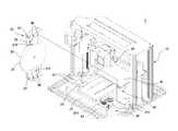
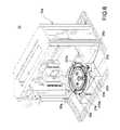
- FIG. 1is a schematic view of removing a scan loading module of a 3D printer of a first exemplary embodiment of this disclosure
- FIG. 2is a schematic view of aligning a driving gear of a 3D printer of the first exemplary embodiment
- FIG. 3is a perspective view of a 3D printer of the first exemplary embodiment
- FIG. 4is a partial schematic view of a scan loading module and a scan driving module combined with each other in accordance with the first exemplary embodiment
- FIG. 5is a schematic view of driving a scanning device of a 3D printer of the first exemplary embodiment
- FIG. 6is a perspective view of a scanning device of a 3D printer in accordance with a second exemplary embodiment of this disclosure
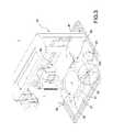
- FIG. 7is a schematic view of removing a scan loading module of a 3D printer of the second exemplary embodiment
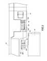
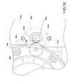
- FIG. 8is a schematic view of aligning a scanning device of a 3D printer of the second exemplary embodiment
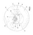
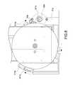
- FIG. 9is a schematic planar view of an aligned scanning device of a 3D printer of the second exemplary embodiment.
- FIG. 10is a schematic view of a scan loading module of a 3D printer driven by a scan driving module of the second exemplary embodiment.
- the 3D printer 1comprises a body 10 , a scan driving module 20 and a scan loading module 30 , wherein the scan driving module 20 and the scan loading module 30 are installed in the body 10 , and the scan loading module is detachably combined with the scan driving module 20 , so as to form a scanning device.
- the 3D printer 1further comprises a printing platform 40 and a printing module 50 .
- a scanning objectis placed onto the scanning device (including the scan driving module 20 and the scan loading module 30 ) and 3D space data of the object is obtained and inputted into a computer graphic software program, an instruction is inputted to control the printing platform 40 and the printing module 50 to execute a printing job.
- the printing platform 40 and the printing module 50are installed in the body 10 , and the printing platform 40 includes a movable printing carrier board 41 .
- the printing module 50is movable in the body 10 and with respect to the printing carrier board 41 .
- the scan driving module 20is installed in the body 10 without interfering the movement of the printing carrier board 41 . After the scan loading module 30 and the scan driving module 20 are positioned with respect to each other, the scan loading module 30 is driven by the scan driving module 20 to rotate.
- the positioning structure of the scan driving module 20 and the scan loading module 30are described specifically below.
- the scan driving module 20comprises a base 21 and a motor 22 installed in the base 21 .
- the motor 22has a driving gear 221 .
- Each gear of the driving gear 221has a first rounded corner 220 .
- the scan loading module 30comprises a loading table 31 , a turntable 32 combined with the loading table 31 and an engaging gear 33 connected to the turntable 32 .
- a side of the loading table 31has a notch 310 , and the engaging gear 33 is exposed from the notch 310 .
- each gear of the engaging gear 33has a second rounded corner 330 .
- the driving gear 221 of the scan driving module 20 and the engaging gear 33 of the scan loading module 30are guided by the first rounded corners 220 (and preferably with the second rounded corners 330 ) and engaged with each other. Therefore, the driving gear 221 is engaged precisely with the engaging gear 33 , such that the scan driving module 20 drives the turntable 32 of the scan loading module 30 to rotate.
- the scan driving module 20further comprises a sensor 23 installed at the base 21
- the scan loading module 30further comprises a blocking elastic arm 311 exposed from the bottom side of the loading table 31 to block the sensor 23 . Therefore, the sensor 23 and the blocking elastic arm 311 may be used to determine whether the loading table 31 has rotated a round with respect to the base 21 .
- each gear of the driving gear 221has a first rounded corner 220
- each gear of the engaging gear 33has a second rounded corner 330 .
- the first rounded corner 220 of the driving gear 221is extended from an end surface 222 of each gear towards a tooth tip 223 of the each gear.
- the second rounded corner 330is also extended from an end surface 223 of each gear towards a tooth tip 332 of each gear.
- the driving gear 221 and the engaging gear 33are engaged, the driving gear 221 and the engaging gear 33 are guided by the rounded corners 220 , 330 and engaged with each other securely. Therefore, the scan driving module 20 and the scan loading module 30 can be aligned precisely to facilitate the operation.
- the base 21 of the scan driving module 20has a plurality of snap members 211
- the scan loading module 30has a plurality of corresponsive snap structures 36 . After the scan driving module 20 and the scan loading module 30 are aligned precisely with each other, the scan loading module 30 is snapped with the snap members 211 through the snap structures 36 and stably combined with the base 21 of the scan driving module 20 .
- the scan loading module 30further has a press button 37 . When it is necessary to remove the scan loading module 30 , the press button 37 of the scan loading module 30 is pressed, so that the snap structures 36 are separated from the snap members 211 , and the scan loading module 30 can be removed from the scan driving module 20 .
- the scan loading module 30 of an exemplary embodimentfurther comprises a reduction gear set 34 connected to the engaging gear 33 and a rotary gear 35 connected to the reduction gear set 34 .
- the rotary gear 35is installed on the bottom side of the turntable 32 . Therefore, the driving gear 221 may be engaged to drive the engaging gear 33 , and the engaging gear 33 drives the reduction gear set 34 .
- the reduction gear set 34is engaged with the rotary gear 35 to drive the turntable 32 , so that the turntable 32 of the scan loading module 30 is driven by the scan driving module 20 to rotate.
- a 3D printer 1 acomprises a body 10 a , a scan driving module 20 a and a scan loading module 30 a , and the scan driving module 20 a and the scan loading module 30 a are detachably combined with the scan driving module 20 a , such that a scanning device is formed in the body 10 a.
- the scan driving module 20 acomprises a base 21 a and a motor 22 a installed in the base 21 a .
- the motor 22 ahas a driving gear 221 a .
- the scan loading module 30 aincludes a loading table 31 a , a turntable 32 a combined with the loading table 31 a and an engaging gear 33 a . Further, a side of the loading table 31 a has a notch 310 a , and the engaging gear 33 a is exposed from the notch 310 a . As shown in FIG.
- the difference between this embodiment and the previous embodimentresides on that the base 21 a has a plurality of first positioning portions 211 a (preferably three or more first positioning portions 211 a ) formed thereon, and the loading table 31 a has a plurality of second positioning portions 311 a (preferably three or more second positioning portions 311 a ) formed thereon and configured to be corresponsive to the first positioning portions 211 a respectively.
- the driving gear 221 a of the scan driving module 20 a and the engaging gear 33 a of the scan loading module 30 aare guided by the first positioning portions 211 a and the second positioning portions 311 a , such that the driving gear 221 a is engaged precisely with the engaging gear 33 a , and the scan driving module 20 a drives the turntable 32 a of the scan loading module 30 a to rotate.
- the first positioning portions 211 aare separated with an interval apart from each other and on the same plane of the base 21 a
- the second positioning portions 311 aare configured to be corresponsive to the first positioning portions 211 a and disposed on the same plane of the loading table 31 a.
- each first positioning portion 211 aincludes a positioning groove 2111 a
- each second positioning portion 311 aincludes a positioning member 3111 a
- the positioning member 3111 ais rotated into the positioning groove 2111 a , so that the base 21 a and the loading table 31 a are positioned with respect to each other.
- the implementation mode of the first positioning portion 211 a and the second positioning portion 311 ais not limited to the aforementioned arrangement only, but any structure capable of positioning the two can be used instead.
- the first positioning portion 211 amay be a positioning member
- the second positioning portion 311 amay be a positioning groove.
- each first positioning portion 211 afurther includes a plug gap 2112 a formed on a side of the positioning groove 2111 a
- each second positioning portion 311 afurther includes a pin 3112 a disposed on a side of the positioning member 3111 a , and the pin 3112 a is inserted into the plug gap 2112 a for the positioning purpose.
- some of the first positioning portions 211 afurther include an engaging hole 2113 a formed on a side of the positioning groove 2111 a
- some of the second positioning portions 311 afurther include a bump 3113 a formed on a side of the positioning member 3111 a , and the bump 3113 a is snapped into the engaging hole 2113 a for the positioning purpose. Therefore, the base 21 a and the loading table 31 a are positioned and combined with each other more precisely.
- the scan loading module 30 afurther comprises a rotary gear 35 a installed on the bottom side of the turntable 32 a .
- the driving gear 221 ais engaged to drive the engaging gear 33 a
- the engaging gear 33 ais engaged with the rotary gear 35 a to drive the turntable 32 a . Therefore, the turntable 32 a of the scan loading module 30 a is driven by the motor 22 a of the scan driving module 20 a to rotate.
Landscapes
- Engineering & Computer Science (AREA)
- Chemical & Material Sciences (AREA)
- Materials Engineering (AREA)
- Manufacturing & Machinery (AREA)
- Physics & Mathematics (AREA)
- Mechanical Engineering (AREA)
- Optics & Photonics (AREA)
- Multimedia (AREA)
- Signal Processing (AREA)
Abstract
Description
Claims (11)
Applications Claiming Priority (2)
| Application Number | Priority Date | Filing Date | Title |
|---|---|---|---|
| CN201510292835.3ACN106273442B (en) | 2015-06-01 | 2015-06-01 | 3D printer scanning device's counterpoint mechanism |
| CN201510292835 | 2015-06-01 |
Publications (1)
| Publication Number | Publication Date |
|---|---|
| US9479667B1true US9479667B1 (en) | 2016-10-25 |
Family
ID=55910784
Family Applications (1)
| Application Number | Title | Priority Date | Filing Date |
|---|---|---|---|
| US14/806,866Expired - Fee RelatedUS9479667B1 (en) | 2015-06-01 | 2015-07-23 | Aligning mechanism of 3D printer scanning device |
Country Status (4)
| Country | Link |
|---|---|
| US (1) | US9479667B1 (en) |
| EP (1) | EP3100845B1 (en) |
| CN (1) | CN106273442B (en) |
| ES (1) | ES2702997T3 (en) |
Cited By (10)
| Publication number | Priority date | Publication date | Assignee | Title |
|---|---|---|---|---|
| RU2649738C1 (en)* | 2017-03-31 | 2018-04-04 | Компания "ФИМАКО МАРКЕТИНГ СА" | 3d-printer |
| CN109068020A (en)* | 2018-08-09 | 2018-12-21 | 重庆工业职业技术学院 | A kind of legal documents quickly identify input device |
| RU2698353C1 (en)* | 2019-04-10 | 2019-08-26 | Георгий Георгиевич Теплинский | 3d-printer |
| CN110754678A (en)* | 2019-11-08 | 2020-02-07 | 内蒙古科技大学 | A parallel robotic arm turntable food 3D printer |
| USD956114S1 (en)* | 2020-01-03 | 2022-06-28 | Anatz Inc. | 3D printer |
| USD958236S1 (en)* | 2020-11-09 | 2022-07-19 | Shenzhen Anycubic Technology Co., Ltd. | 3D printer |
| USD1048121S1 (en)* | 2022-07-29 | 2024-10-22 | Shenzhen Snapmaker Technologies Co., Ltd. | 3D printer |
| USD1050203S1 (en)* | 2023-09-11 | 2024-11-05 | Shenzhen Tuozhu Technology Co., Ltd. | 3D printer |
| USD1050204S1 (en)* | 2023-07-27 | 2024-11-05 | Shenzhen Tuozhu Technology Co., Ltd. | 3D printer |
| USD1098216S1 (en)* | 2023-07-25 | 2025-10-14 | Shenzhen Tuozhu Technology Co., Ltd. | Automated material system for 3D printer |
Citations (16)
| Publication number | Priority date | Publication date | Assignee | Title |
|---|---|---|---|---|
| US20010019340A1 (en)* | 2000-02-29 | 2001-09-06 | Minolta, Co., Ltd. | Three-dimensional object printing apparatus and method |
| US20060147188A1 (en)* | 2005-01-06 | 2006-07-06 | Weng Jia D | Three-dimensional photographic shelf |
| US20070035539A1 (en)* | 2003-08-21 | 2007-02-15 | Koichi Matsumura | Image acquisition system for generation of three-dimensional models |
| US8285130B1 (en)* | 2011-06-17 | 2012-10-09 | Ortery Technologies, Inc. | Photography studio with turntable driving mechanism |
| US20140265034A1 (en)* | 2013-03-12 | 2014-09-18 | Orange Maker LLC | 3d printing using spiral buildup |
| US20140271964A1 (en)* | 2013-03-15 | 2014-09-18 | Matterrise, Inc. | Three-Dimensional Printing and Scanning System and Method |
| US20140374949A1 (en)* | 2013-06-25 | 2014-12-25 | Cal-Comp Precision (Singapore) Limited | Three-dimensional printing apparatus and pringing method thereof |
| US20150054918A1 (en)* | 2013-08-23 | 2015-02-26 | Xyzprinting, Inc. | Three-dimensional scanner |
| US20150057785A1 (en)* | 2013-08-23 | 2015-02-26 | Xyzprinting, Inc. | Three-dimensional printing apparatus and three-dimensional preview and printing method thereof |
| US20150110912A1 (en)* | 2013-10-18 | 2015-04-23 | Roland Dg Corporation | Three-dimensional printing apparatus |
| US20150170009A1 (en)* | 2013-12-17 | 2015-06-18 | International Business Machines Corporation | Pausing and resuming a three-dimensional printjob |
| US20150298395A1 (en)* | 2014-04-18 | 2015-10-22 | Delta Electronics, Inc. | 3d scanning-printing device |
| US20150319418A1 (en)* | 2012-12-02 | 2015-11-05 | Segoma Ltd. | Devices and methods for generating a 3d imaging dataset of an object |
| US20160052210A1 (en)* | 2014-08-19 | 2016-02-25 | National Taiwan University Of Science And Technology | Multifunctional 3d scanning and printing apparatus |
| US9358728B1 (en)* | 2014-11-13 | 2016-06-07 | Xyzprinting, Inc. | 3D printer |
| US20160176108A1 (en)* | 2014-12-23 | 2016-06-23 | NEA 3D Inc. | 3D printer and scanner mechanisms |
Family Cites Families (5)
| Publication number | Priority date | Publication date | Assignee | Title |
|---|---|---|---|---|
| CN101320473B (en)* | 2008-07-01 | 2011-07-20 | 上海大学 | Free multi-vision angle, real-time three-dimensional reconstruction system and method |
| US20160039149A1 (en)* | 2013-04-04 | 2016-02-11 | Leonard J. Cassara | Rapid prototype system having interchangeable modules |
| DE202013103446U1 (en)* | 2013-07-31 | 2013-08-26 | Tangible Engineering Gmbh | Compact apparatus for producing a three-dimensional object by solidifying a photo-hardening material |
| CN103729883B (en)* | 2013-12-30 | 2016-08-24 | 浙江大学 | A kind of three-dimensional environment information gathering and reconfiguration system and method |
| CN104299266B (en)* | 2014-10-23 | 2017-02-15 | 西安工业大学 | Scanning device of false tooth cavity preparation body with inverted recess |
- 2015
- 2015-06-01CNCN201510292835.3Apatent/CN106273442B/ennot_activeExpired - Fee Related
- 2015-07-23USUS14/806,866patent/US9479667B1/ennot_activeExpired - Fee Related
- 2016
- 2016-04-29EPEP16167714.1Apatent/EP3100845B1/ennot_activeNot-in-force
- 2016-04-29ESES16167714Tpatent/ES2702997T3/enactiveActive
Patent Citations (17)
| Publication number | Priority date | Publication date | Assignee | Title |
|---|---|---|---|---|
| US20010019340A1 (en)* | 2000-02-29 | 2001-09-06 | Minolta, Co., Ltd. | Three-dimensional object printing apparatus and method |
| US20070035539A1 (en)* | 2003-08-21 | 2007-02-15 | Koichi Matsumura | Image acquisition system for generation of three-dimensional models |
| US20060147188A1 (en)* | 2005-01-06 | 2006-07-06 | Weng Jia D | Three-dimensional photographic shelf |
| US8285130B1 (en)* | 2011-06-17 | 2012-10-09 | Ortery Technologies, Inc. | Photography studio with turntable driving mechanism |
| US20150319418A1 (en)* | 2012-12-02 | 2015-11-05 | Segoma Ltd. | Devices and methods for generating a 3d imaging dataset of an object |
| US20140265034A1 (en)* | 2013-03-12 | 2014-09-18 | Orange Maker LLC | 3d printing using spiral buildup |
| US20140271964A1 (en)* | 2013-03-15 | 2014-09-18 | Matterrise, Inc. | Three-Dimensional Printing and Scanning System and Method |
| US9364995B2 (en)* | 2013-03-15 | 2016-06-14 | Matterrise, Inc. | Three-dimensional printing and scanning system and method |
| US20140374949A1 (en)* | 2013-06-25 | 2014-12-25 | Cal-Comp Precision (Singapore) Limited | Three-dimensional printing apparatus and pringing method thereof |
| US20150054918A1 (en)* | 2013-08-23 | 2015-02-26 | Xyzprinting, Inc. | Three-dimensional scanner |
| US20150057785A1 (en)* | 2013-08-23 | 2015-02-26 | Xyzprinting, Inc. | Three-dimensional printing apparatus and three-dimensional preview and printing method thereof |
| US20150110912A1 (en)* | 2013-10-18 | 2015-04-23 | Roland Dg Corporation | Three-dimensional printing apparatus |
| US20150170009A1 (en)* | 2013-12-17 | 2015-06-18 | International Business Machines Corporation | Pausing and resuming a three-dimensional printjob |
| US20150298395A1 (en)* | 2014-04-18 | 2015-10-22 | Delta Electronics, Inc. | 3d scanning-printing device |
| US20160052210A1 (en)* | 2014-08-19 | 2016-02-25 | National Taiwan University Of Science And Technology | Multifunctional 3d scanning and printing apparatus |
| US9358728B1 (en)* | 2014-11-13 | 2016-06-07 | Xyzprinting, Inc. | 3D printer |
| US20160176108A1 (en)* | 2014-12-23 | 2016-06-23 | NEA 3D Inc. | 3D printer and scanner mechanisms |
Cited By (10)
| Publication number | Priority date | Publication date | Assignee | Title |
|---|---|---|---|---|
| RU2649738C1 (en)* | 2017-03-31 | 2018-04-04 | Компания "ФИМАКО МАРКЕТИНГ СА" | 3d-printer |
| CN109068020A (en)* | 2018-08-09 | 2018-12-21 | 重庆工业职业技术学院 | A kind of legal documents quickly identify input device |
| RU2698353C1 (en)* | 2019-04-10 | 2019-08-26 | Георгий Георгиевич Теплинский | 3d-printer |
| CN110754678A (en)* | 2019-11-08 | 2020-02-07 | 内蒙古科技大学 | A parallel robotic arm turntable food 3D printer |
| USD956114S1 (en)* | 2020-01-03 | 2022-06-28 | Anatz Inc. | 3D printer |
| USD958236S1 (en)* | 2020-11-09 | 2022-07-19 | Shenzhen Anycubic Technology Co., Ltd. | 3D printer |
| USD1048121S1 (en)* | 2022-07-29 | 2024-10-22 | Shenzhen Snapmaker Technologies Co., Ltd. | 3D printer |
| USD1098216S1 (en)* | 2023-07-25 | 2025-10-14 | Shenzhen Tuozhu Technology Co., Ltd. | Automated material system for 3D printer |
| USD1050204S1 (en)* | 2023-07-27 | 2024-11-05 | Shenzhen Tuozhu Technology Co., Ltd. | 3D printer |
| USD1050203S1 (en)* | 2023-09-11 | 2024-11-05 | Shenzhen Tuozhu Technology Co., Ltd. | 3D printer |
Also Published As
| Publication number | Publication date |
|---|---|
| EP3100845B1 (en) | 2018-10-31 |
| ES2702997T3 (en) | 2019-03-06 |
| EP3100845A1 (en) | 2016-12-07 |
| CN106273442B (en) | 2018-06-08 |
| CN106273442A (en) | 2017-01-04 |
Similar Documents
| Publication | Publication Date | Title |
|---|---|---|
| US9479667B1 (en) | Aligning mechanism of 3D printer scanning device | |
| KR101749795B1 (en) | Apparatus of separating flexible substrate from glass substrate and manufacturing equipment thereof | |
| CN205798724U (en) | Monochromatic light road many cutting heads tool | |
| CN105959450A (en) | Fixture, automatic testing mechanical arm and automatic testing system | |
| TWI617518B (en) | Flip device | |
| WO2015177834A1 (en) | Component mounting apparatus and method for arranging component mounting apparatus | |
| KR101493597B1 (en) | Tip holder storage body | |
| CN105690291A (en) | Fixing device | |
| US10259162B2 (en) | Laser module with detachable structures of three-dimensional printer | |
| CN106455473B (en) | Pallet conveying device and mounting device | |
| JP2018127332A (en) | Conveyance system | |
| CN206445374U (en) | The module tablet laser cutting upset tool of falling disk | |
| JP6254004B2 (en) | Feeder position determination device and electronic component mounting device having the same | |
| CN206316785U (en) | Four-sided milling fixture | |
| JP6552386B2 (en) | Component mounting machine, component mounting method | |
| JP2015135835A (en) | Alignment device for components | |
| CN207844322U (en) | Guide device | |
| JP2017052599A (en) | Transfer device and control method of transfer device | |
| JP6995515B2 (en) | Labeling device and labeling robot | |
| CN204397670U (en) | Camera lens circle accurate positioning device | |
| EP3923692A1 (en) | Mounting-related device and rail device | |
| WO2014129195A1 (en) | Component mounting device, and component mounting method | |
| JP2021064689A (en) | Transport method and transport device | |
| CN205199832U (en) | Gluing machine | |
| CN204549417U (en) | A kind of automatic loading and unloading mechanism |
Legal Events
| Date | Code | Title | Description |
|---|---|---|---|
| AS | Assignment | Owner name:XYZPRINTING, INC., TAIWAN Free format text:ASSIGNMENT OF ASSIGNORS INTEREST;ASSIGNORS:LEE, YANG-TEH;JUANG, JIA-YI;LIU, JEN-HSIANG;AND OTHERS;REEL/FRAME:036162/0601 Effective date:20150721 Owner name:KINPO ELECTRONICS, INC., TAIWAN Free format text:ASSIGNMENT OF ASSIGNORS INTEREST;ASSIGNORS:LEE, YANG-TEH;JUANG, JIA-YI;LIU, JEN-HSIANG;AND OTHERS;REEL/FRAME:036162/0601 Effective date:20150721 Owner name:CAL-COMP ELECTRONICS & COMMUNICATIONS COMPANY LIMI Free format text:ASSIGNMENT OF ASSIGNORS INTEREST;ASSIGNORS:LEE, YANG-TEH;JUANG, JIA-YI;LIU, JEN-HSIANG;AND OTHERS;REEL/FRAME:036162/0601 Effective date:20150721 | |
| ZAAA | Notice of allowance and fees due | Free format text:ORIGINAL CODE: NOA | |
| ZAAB | Notice of allowance mailed | Free format text:ORIGINAL CODE: MN/=. | |
| STCF | Information on status: patent grant | Free format text:PATENTED CASE | |
| MAFP | Maintenance fee payment | Free format text:PAYMENT OF MAINTENANCE FEE, 4TH YEAR, LARGE ENTITY (ORIGINAL EVENT CODE: M1551); ENTITY STATUS OF PATENT OWNER: LARGE ENTITY Year of fee payment:4 | |
| FEPP | Fee payment procedure | Free format text:MAINTENANCE FEE REMINDER MAILED (ORIGINAL EVENT CODE: REM.); ENTITY STATUS OF PATENT OWNER: LARGE ENTITY | |
| LAPS | Lapse for failure to pay maintenance fees | Free format text:PATENT EXPIRED FOR FAILURE TO PAY MAINTENANCE FEES (ORIGINAL EVENT CODE: EXP.); ENTITY STATUS OF PATENT OWNER: LARGE ENTITY | |
| STCH | Information on status: patent discontinuation | Free format text:PATENT EXPIRED DUE TO NONPAYMENT OF MAINTENANCE FEES UNDER 37 CFR 1.362 | |
| FP | Lapsed due to failure to pay maintenance fee | Effective date:20241025 |