US9479240B1 - Composite beamforming to coordinate concurrent WLAN links - Google Patents
Composite beamforming to coordinate concurrent WLAN linksDownload PDFInfo
- Publication number
- US9479240B1 US9479240B1US14/612,293US201514612293AUS9479240B1US 9479240 B1US9479240 B1US 9479240B1US 201514612293 AUS201514612293 AUS 201514612293AUS 9479240 B1US9479240 B1US 9479240B1
- Authority
- US
- United States
- Prior art keywords
- primary beam
- wap
- downlink
- nodes
- communications
- Prior art date
- Legal status (The legal status is an assumption and is not a legal conclusion. Google has not performed a legal analysis and makes no representation as to the accuracy of the status listed.)
- Active, expires
Links
- 239000002131composite materialSubstances0.000titleclaimsdescription19
- 238000004891communicationMethods0.000claimsabstractdescription135
- 230000002452interceptive effectEffects0.000claimsabstractdescription30
- 238000000034methodMethods0.000claimsdescription47
- 239000003999initiatorSubstances0.000claimsdescription28
- 230000000977initiatory effectEffects0.000claimsdescription11
- 230000004931aggregating effectEffects0.000claims4
- 230000008569processEffects0.000description31
- 238000010586diagramMethods0.000description25
- 239000011159matrix materialSubstances0.000description16
- 230000003071parasitic effectEffects0.000description9
- 230000000875corresponding effectEffects0.000description8
- 230000000694effectsEffects0.000description5
- 238000000926separation methodMethods0.000description5
- 238000012544monitoring processMethods0.000description4
- 238000012545processingMethods0.000description4
- 239000013598vectorSubstances0.000description4
- 230000005540biological transmissionEffects0.000description3
- 238000006243chemical reactionMethods0.000description3
- 238000013213extrapolationMethods0.000description3
- 230000002776aggregationEffects0.000description2
- 238000004220aggregationMethods0.000description2
- 230000008901benefitEffects0.000description2
- 239000000872bufferSubstances0.000description2
- 230000008859changeEffects0.000description2
- HPNSNYBUADCFDR-UHFFFAOYSA-NchromafenozideChemical compoundCC1=CC(C)=CC(C(=O)N(NC(=O)C=2C(=C3CCCOC3=CC=2)C)C(C)(C)C)=C1HPNSNYBUADCFDR-UHFFFAOYSA-N0.000description2
- 230000002596correlated effectEffects0.000description2
- 230000008878couplingEffects0.000description2
- 238000010168coupling processMethods0.000description2
- 238000005859coupling reactionMethods0.000description2
- 230000003247decreasing effectEffects0.000description2
- 238000013507mappingMethods0.000description2
- 239000000969carrierSubstances0.000description1
- 230000001351cycling effectEffects0.000description1
- 230000001419dependent effectEffects0.000description1
- 229920005994diacetyl cellulosePolymers0.000description1
- 238000011156evaluationMethods0.000description1
- 239000004744fabricSubstances0.000description1
- 230000006870functionEffects0.000description1
- 230000005055memory storageEffects0.000description1
- 238000012986modificationMethods0.000description1
- 230000004048modificationEffects0.000description1
- 230000000737periodic effectEffects0.000description1
- 230000004044responseEffects0.000description1
- 238000005070samplingMethods0.000description1
- 238000007493shaping processMethods0.000description1
- 238000012360testing methodMethods0.000description1
- 230000001960triggered effectEffects0.000description1
Images


Classifications
- H—ELECTRICITY
- H04—ELECTRIC COMMUNICATION TECHNIQUE
- H04B—TRANSMISSION
- H04B7/00—Radio transmission systems, i.e. using radiation field
- H04B7/02—Diversity systems; Multi-antenna system, i.e. transmission or reception using multiple antennas
- H04B7/04—Diversity systems; Multi-antenna system, i.e. transmission or reception using multiple antennas using two or more spaced independent antennas
- H04B7/06—Diversity systems; Multi-antenna system, i.e. transmission or reception using multiple antennas using two or more spaced independent antennas at the transmitting station
- H04B7/0613—Diversity systems; Multi-antenna system, i.e. transmission or reception using multiple antennas using two or more spaced independent antennas at the transmitting station using simultaneous transmission
- H04B7/0615—Diversity systems; Multi-antenna system, i.e. transmission or reception using multiple antennas using two or more spaced independent antennas at the transmitting station using simultaneous transmission of weighted versions of same signal
- H04B7/0617—Diversity systems; Multi-antenna system, i.e. transmission or reception using multiple antennas using two or more spaced independent antennas at the transmitting station using simultaneous transmission of weighted versions of same signal for beam forming
- H—ELECTRICITY
- H04—ELECTRIC COMMUNICATION TECHNIQUE
- H04B—TRANSMISSION
- H04B7/00—Radio transmission systems, i.e. using radiation field
- H04B7/02—Diversity systems; Multi-antenna system, i.e. transmission or reception using multiple antennas
- H04B7/022—Site diversity; Macro-diversity
- H04B7/024—Co-operative use of antennas of several sites, e.g. in co-ordinated multipoint or co-operative multiple-input multiple-output [MIMO] systems
- H—ELECTRICITY
- H04—ELECTRIC COMMUNICATION TECHNIQUE
- H04B—TRANSMISSION
- H04B7/00—Radio transmission systems, i.e. using radiation field
- H04B7/02—Diversity systems; Multi-antenna system, i.e. transmission or reception using multiple antennas
- H04B7/04—Diversity systems; Multi-antenna system, i.e. transmission or reception using multiple antennas using two or more spaced independent antennas
- H04B7/0413—MIMO systems
- H—ELECTRICITY
- H04—ELECTRIC COMMUNICATION TECHNIQUE
- H04B—TRANSMISSION
- H04B7/00—Radio transmission systems, i.e. using radiation field
- H04B7/02—Diversity systems; Multi-antenna system, i.e. transmission or reception using multiple antennas
- H04B7/04—Diversity systems; Multi-antenna system, i.e. transmission or reception using multiple antennas using two or more spaced independent antennas
- H04B7/06—Diversity systems; Multi-antenna system, i.e. transmission or reception using multiple antennas using two or more spaced independent antennas at the transmitting station
- H04B7/0602—Diversity systems; Multi-antenna system, i.e. transmission or reception using multiple antennas using two or more spaced independent antennas at the transmitting station using antenna switching
- H04B7/0608—Antenna selection according to transmission parameters
- H04B7/061—Antenna selection according to transmission parameters using feedback from receiving side
- H—ELECTRICITY
- H04—ELECTRIC COMMUNICATION TECHNIQUE
- H04B—TRANSMISSION
- H04B7/00—Radio transmission systems, i.e. using radiation field
- H04B7/02—Diversity systems; Multi-antenna system, i.e. transmission or reception using multiple antennas
- H04B7/04—Diversity systems; Multi-antenna system, i.e. transmission or reception using multiple antennas using two or more spaced independent antennas
- H04B7/06—Diversity systems; Multi-antenna system, i.e. transmission or reception using multiple antennas using two or more spaced independent antennas at the transmitting station
- H04B7/0613—Diversity systems; Multi-antenna system, i.e. transmission or reception using multiple antennas using two or more spaced independent antennas at the transmitting station using simultaneous transmission
- H04B7/0615—Diversity systems; Multi-antenna system, i.e. transmission or reception using multiple antennas using two or more spaced independent antennas at the transmitting station using simultaneous transmission of weighted versions of same signal
- H04B7/0619—Diversity systems; Multi-antenna system, i.e. transmission or reception using multiple antennas using two or more spaced independent antennas at the transmitting station using simultaneous transmission of weighted versions of same signal using feedback from receiving side
- H04B7/0621—Feedback content
- H04B7/0626—Channel coefficients, e.g. channel state information [CSI]
- H—ELECTRICITY
- H04—ELECTRIC COMMUNICATION TECHNIQUE
- H04L—TRANSMISSION OF DIGITAL INFORMATION, e.g. TELEGRAPHIC COMMUNICATION
- H04L27/00—Modulated-carrier systems
- H04L27/26—Systems using multi-frequency codes
- H04L27/2601—Multicarrier modulation systems
- H04L27/2626—Arrangements specific to the transmitter only
- H04L27/2646—Arrangements specific to the transmitter only using feedback from receiver for adjusting OFDM transmission parameters, e.g. transmission timing or guard interval length
- H04W72/042—
- H—ELECTRICITY
- H04—ELECTRIC COMMUNICATION TECHNIQUE
- H04W—WIRELESS COMMUNICATION NETWORKS
- H04W72/00—Local resource management
- H04W72/04—Wireless resource allocation
- H04W72/044—Wireless resource allocation based on the type of the allocated resource
- H—ELECTRICITY
- H04—ELECTRIC COMMUNICATION TECHNIQUE
- H04W—WIRELESS COMMUNICATION NETWORKS
- H04W74/00—Wireless channel access
- H04W74/08—Non-scheduled access, e.g. ALOHA
- H04W74/0808—Non-scheduled access, e.g. ALOHA using carrier sensing, e.g. carrier sense multiple access [CSMA]
- H04W74/0816—Non-scheduled access, e.g. ALOHA using carrier sensing, e.g. carrier sense multiple access [CSMA] with collision avoidance
- H—ELECTRICITY
- H04—ELECTRIC COMMUNICATION TECHNIQUE
- H04W—WIRELESS COMMUNICATION NETWORKS
- H04W84/00—Network topologies
- H04W84/02—Hierarchically pre-organised networks, e.g. paging networks, cellular networks, WLAN [Wireless Local Area Network] or WLL [Wireless Local Loop]
- H04W84/10—Small scale networks; Flat hierarchical networks
- H04W84/12—WLAN [Wireless Local Area Networks]
- H—ELECTRICITY
- H04—ELECTRIC COMMUNICATION TECHNIQUE
- H04L—TRANSMISSION OF DIGITAL INFORMATION, e.g. TELEGRAPHIC COMMUNICATION
- H04L27/00—Modulated-carrier systems
- H04L27/26—Systems using multi-frequency codes
- H04L27/2601—Multicarrier modulation systems
Definitions
- the field of the present inventionrelates in general to wireless local area networks including wireless access points (WAP) and wireless stations and methods of coordinating transmissions thereon.
- WAPwireless access points
- WLANwireless local area networks
- WAPWireless Access Points
- Each WAPwirelessly couples all associated devices, e.g. wireless stations such as: computers, printers, televisions, security cameras across the entire enterprise to one another and to the Internet.
- Most WAPsimplement the IEEE 802.11 standard which is a contention based standard for handling communications among multiple competing devices for a shared wireless communication medium on a selected one of a plurality of communication channels.
- the frequency range of each communication channelis specified in the corresponding one of the protocols, e.g. “a”, “b”, “g”, “n”, “ac”, “ad” specified in the IEEE 802.11 standard.
- Communicationsfollow a hub and spoke model with each WAP at the hub and the spokes corresponding to the wireless links to each ‘client’ device.
- a communication between from a transmitting WAP and one of its associated receiving stationsis identified as a downlink communication.
- a communication from a transmitting station to its receiving WAP with which it is associatedis identified as an uplink communication.
- CSMACollision Sense Multiple Access
- a WLAN operative in this manneris said to implement: CSMA ⁇ CA where the “CA” moniker signifies collision avoidance as the connectionless access coordination methodology.
- Communications on the single communication mediumare identified as “simplex” meaning, communications from a single source node to one target node at one time, with all remaining nodes capable of “listening” to the subject transmission.
- discrete communications to more than one target node at the same timemay take place using what is called Multi-User (MU) multiple-input multiple-output (MIMO) capability of the WAP.
- MU capabilitieswere added to the standard to enable the WAP to communicate with multiple single antenna single stream devices concurrently, thereby increasing the time available for discrete MIMO links to contending wireless devices.
- An Enterprise WLANmay consist of hundreds or thousands of WAPs each supporting communications of hundreds of associated wireless communication devices and the Internet on its own sub-net and all collectively operating under control of the central controller.
- Each WAPuses the same Service Set Identifier (SSID) for station association.
- SSIDService Set Identifier
- the central controllerwill typically assign the different channels to selected subsets of the WAPS. This allows concurrent communications to take place on different channels while still maintaining compliance with the CSMA ⁇ CA protocol.
- Unfortunately, such throughput improvements achieved by frequency separationcome at the price of decreased bandwidth for communications, which of course has its own countervailing effect on throughput. This tradeoff is particularly noticeable in the more recent IEEE 802.11 compliant protocols such as 802.11ac.
- This protocolallows channel aggregation of the many discrete 20 Mhz channels into aggregate channels totaling 160 Mhz. This broad bandwidth may be required for wireless video conferencing devices and other low latency high throughput enterprise devices. Thus the central controller is left with the tradeoffs between frequency separation between proximate WAPs at the price of decreased bandwidth.
- WLANwireless local area networks
- the present inventionprovides a system, method and apparatus for increasing overall communication throughput on wireless local area network (WLAN) comprising a plurality of multiple-input multiple-output (MIMO) Wireless Access Points (WAP)s communicating with associated stations which are all compliant, with one or more of the protocols e.g. “a”, “b”, “g”, “n”, “ac”, “ad” within the IEEE 802.11 standard.
- WLANwireless local area network
- MIMOmultiple-input multiple-output
- WAPWireless Access Points
- a system for coordinating a WLANincluding a plurality of MIMO WAP nodes each supporting WLAN communications with an associated set of station nodes on a shared OFDM communication channel.
- the systemcomprises a primary beam coordinator and the plurality of WAP nodes.
- the primary beam coordinatorcouples to the plurality of WAP nodes and is configured to aggregate channel state information (CSI) for communication links and crosslinks between each WAP node and both associated and non-associated station nodes thereof and to extrapolate therefrom spatially distinct primary beam pattern setup options to each of the plurality of WAP nodes to enable substantially non-interfering concurrent downlink communications between each WAP node and a corresponding subset of its associated station nodes within each associated spatially distinct primary beam.
- CSIchannel state information
- the plurality of WAP nodesare each coupled to the primary beam coordinator and configured to select a corresponding one of the primary beam options together with its associated stations as provided by the primary beam coordinator and to generate the corresponding selected primary beam option for subsequent downlink communications to at least one of the associated subset of station nodes; thereby increasing a downlink throughput of the WLAN via non-interfering concurrent downlink communications thereon.
- the inventionmay be implemented in hardware, firmware or software.
- FIGS. 1A-Dare respectively a prior art elevation view, plan view, network view and channel bandplan for a representative prior art Enterprise wireless local area network (WLAN);
- WLANwireless local area network
- FIGS. 2A-Care respectively a beamforming diagram and network diagrams for an embodiment of the invention for coordinating concurrent 1 Q Enterprise WLAN links;
- FIGS. 3A-Dare network diagrams of various stages of the coordination of concurrent Enterprise WLAN links in accordance with an embodiment of the invention.
- FIG. 4is a data structure diagram showing representative primary beam coordination data uploaded by a primary beam coordinator and the extrapolation of that data into spatially distinct primary beam setup options for distribution to each WAP;
- FIGS. 5A-Care detailed hardware block diagrams of a wireless access point (WAP) showing alternate embodiments of the invention for generating a composite beam for downlink communications including a primary beam specified by the primary beam coordinator and secondary beam determined by each WAP;
- WAPwireless access point
- FIG. 6is a hardware block diagram at a system level of both the primary beam coordinator coupled to all WAPs and the primary beam servo in each WAP in an embodiment of the current invention.
- FIGS. 7A-Bare process flow diagrams of the processes associated with coordinating concurrent WLAN links on both the primary beam coordinator coupled to all WAPs and the primary beam servo in each WAP, in accordance with an embodiment of the current invention.
- FIGS. 1A-Dare respectively a prior art elevation view, plan view, network view and channel bandplan for a representative prior art Enterprise wireless local area network (WLAN).
- WLANwireless local area network
- FIG. 1Ais the elevation view of a prior art enterprise WLAN deployed in a school or business auditorium 100 .
- WLAN serviceis provided to the thousands of people in the audience and their associated wireless devices via a grid of WAPs 120 - 190 positioned across the ceiling of the auditorium.
- FIG. 1Bshows the plan view of the prior art Enterprise WLAN shown in FIG. 1A .
- Each of WAPs 130 , 140 , 170 and 180operated on one of the selectable communication channels, e.g. Channel 8.
- Remaining WAPs 120 , 150 , 160 , 190operate on another of the selectable communication channels, e.g. Channel 6.
- This frequency separationallows for increased concurrency in WLAN communications at the expense of limited bandwidth.
- All WAPsare coupled to the Enterprise controller 102 which controls channel selection for all the WAPs.
- Each WAPservices its own associated set of stations 112 . All WAPs share a common Service Set Identifier (SSID).
- SSIDService Set Identifier
- FIG. 1Cshows the network view of the prior art Enterprise WLAN shown in FIG. 1B and specifically those WAPs 120 , 150 , 160 , 190 operating on Channel 6.
- WAP 150gains access to the medium, i.e. Channel 6, for a downlink communication 154 D to target station 156 D.
- Downlinks from each WAPare not limited to a single target station.
- MUmulti-user
- MIMOMultiple-Input Multiple-Output
- adjacent WAPs 120 and 160operate in a manner consistent with the Carrier Sense Multiple Access (CSMA) protocol identified as Collision Avoidance (CA), by detecting the energy from link 154 D and avoid access to the channel and resultant interference with link 154 D until that downlink is completed. Not all concurrent downlinks by different WAPs on the same channel are blocked.
- CSMACarrier Sense Multiple Access
- CACollision Avoidance
- WAPs 150 and 190 concurrent downlinkscan take place without mutual interference, e.g. downlink 194 F from WAP 190 to station 196 F. Nevertheless it remains the case with prior art Enterprise WEAN deployments that there any many blocked downlinks on adjacent WQAPS sharing the same communication channel.
- FIG. 1Dshows the network bandplan associated with a portion of the IEEE 802.11ac protocol.
- a number of 20 Mhz channels 150 , 152 , 154 , 156 , 158 , 160 , 162 , 164are shown.
- Each channelincludes multiple sub-carriers, a.k.a. tones, a.k.a. sub-channels, e.g. tones 150 A-B for channel 150 .
- These channelsmay be allocated individually to each WAP but doing so would reduce practicable throughput for video conference and other low latency and high throughput wireless devices to unacceptably low levels.
- channelscan be aggregated with a single 160 MHz channel being allocated to each WAP, with the problem of unacceptably high levels of collision between downlinks of adjacent WAPs sharing the 160 Mhz aggregate communication channel.
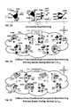
- FIGS. 2A-Care respectively a beamforming diagram and network diagrams for an embodiment of the invention for coordinating concurrent Enterprise WLAN links.
- FIG. 2Ais the beamforming diagram showing composite beamforms and associated RF signal strength patterns generated by WAP 200 at times t 0 -t 6 .
- Each composite beam shown at times t 0 , t 1 , t 5 , and t 6arises from the superposition of a primary beam shown in black and one or more secondary beams shown in grey and having a generally “tear drop” shape. These representations are illustrative only.
- Composite beamsare shown at times t 0 -t 6 .
- the primary beam and or its associated setup parametersis identified by the primary beam coordinator 212 shown in the following FIGS. 2B-2C as coupled to all the WAPs.
- the secondary beamsare determined by each WAP.
- WAP 200has generated a composite beam consisting of primary beam 202 A and a secondary beam 204 A.
- a number of stationsare associated with the WAP and only a cluster or subset 208 A thereof fall within the coverage of primary beam 202 A.
- the WAPdetermines which stations in the cluster to communicate with based on its own internal downlink demand indicators such as the depth of the associated transmit buffers for each target station in the cluster.
- At time t 0 WAP 200has generated a secondary beam 204 A to support the downlink communication with station 206 A.
- WAP 200has generated another secondary beam 204 B to support the downlink communication with station 206 B.
- Downlinks by WAP 200 to remaining ones of its associated stationsrequires a change in the spatial orientation of the primary beam which is shown to occur at time t 3 on the WAP 200 .
- a primary beam 202 Bis shown along with its associated subset or cluster 208 B of stations 206 C, 206 D, 206 E associated therewith.
- the WAPdetermines which stations in its associated cluster to communicate with based on its own internal downlink demand indicators such as the depth of the associated transmit buffers for each target station in the cluster.
- WAP 200has generated secondary beams 204 C, 204 E to support MU-MIMO downlink communication to stations 206 C, 206 E respectively.
- WAP 200chooses to communicate with another of the subset of stations which falls within the primary beam and in this case generates another secondary beam 204 D to link it to another of the subset of stations that fall within primary beam 2026 in this case station 206 D.
- FIGS. 2B-2Care network diagrams showing coordination by primary beam coordinator 212 of the primary beam portion of each composite beam across the entire Enterprise WLAN 214 serviced by WAPs 220 , 230 , 240 , 250 , 260 , 270 , 280 , 290 .
- FIGS. 2B and 2Cshow representative WLAN operation during the intervals t 7 -t 7+ ⁇ and t 8 -t 8+ ⁇ respectively.
- the entire WLANmaintains CSMA ⁇ CA compliance with significantly increased throughput due to primary beam coordination between WAPs sharing the channel which results in a significant increase of concurrent downlinks that do not interfere with one another. All WAPs are shown with multi user or single user concurrent downlinks.
- WAP 220obtains initial CSMA ⁇ CA access to channel 6 thus triggering the onset of coordinated concurrent downlinks by other temporarily “blocked” follower WAPs sharing the same channel, e.g. WAPs 250 , 260 , 290 .
- WAP 290generates downlinks on a primary beam and secondary beams 294 B, 294 D.
- WAP 220gains access to the medium, i.e. shared communication channel, e.g. channel “6”, the remaining WAPs sharing that channel and detecting the access by WAP 220 , back off trying to access the medium. This is consistent with CSMA ⁇ CA collision avoidance.
- the remaining WAPsreceive notification from the primary coordinator as to primary beam patterns they can generate which do not spatially overlap with the primary beam pattern 222 A used by WP 220 . Similar coordination applies to the activity on the WAPs sharing channel 8.
- WAP 270 on channel 8obtains initial CSMA access to the channel thus triggering the onset of coordinated concurrent downlinks by other temporarily “blocked” follower WAPs sharing the same channel.
- WAP 230generates MU-MIMO downlinks on a composite beam comprising primary beam 232 D and secondary beams 234 G, 234 H.
- This coordinating information triggered by the initiator WAP gaining access to the mediumtakes time to propagate through the network to the other WAPs in follower mode, e.g. WAPs 250 , 260 , 290 for channel 6 and WAPs 230 , 240 , 280 for channel 8. This time is on the order of one or two symbol intervals and is why the time intervals are represented with the delta terminology.
- WAP 250obtains initial CSMA ⁇ CA access to channel 6 and uses primary barn 252 D for its downlink. This triggers the onset of coordinated concurrent downlinks by other temporarily “blocked” follower WAPs sharing the same channel, e.g. WAPs 220 , 260 , 290 .
- Follower WAP 220generates MU-MIMO downlinks on its designated primary beam and secondary beams 224 E, 224 G. Similar coordination applies to the activity on the WAPs sharing Channel 8.
- WAP 240 on channel 8obtains initial CSMA access to the channel and generates a composite beam including primary beam 242 E and secondary beam 244 B. This triggers the onset of coordinated concurrent downlinks by other temporarily “blocked” follower WAPs sharing the same channel, e.g. WAPs 230 , 270 , 280 .
- FIGS. 3A-Dare network diagrams of various stages of the coordination of concurrent Enterprise WLAN links in accordance with an embodiment of the invention.
- a primary beam coordinator 302is shown coordinating downlink communications on the WLAN 304 including WAPs. 320 , 330 , 340 , 350 , 360 , 370 , 380 , 390 to all stations, e.g. stations
- FIG. 3Ais the network diagram of an aggregation stage in the coordination of concurrent Enterprise WLAN links in accordance with an embodiment of the invention.
- link and crosslink channel state informationis uploaded from each WAP to the primary beam coordinator.
- a crosslinkis an uplink from a transmitting station as monitored by a WAP with which it is not associated.
- the data uploaded 306 A-B by each WAP to the primary beam coordinatoris the slow varying relatively stable portion of the CSI data associated with each link and crosslink. This data is used by the primary beam coordinator to determine primary beams and associated station subsets that are spatially isolatable from one another.
- each WAPincludes an electronically steerable antenna array such as a phased array or an electronically steerable parasitic array.
- monitoringmay include cycling the receive antenna array of each WAP through different spatial orientations while sampling each uplink and crosslink.
- each WAPwill upload CSI information sufficient for the central beam coordinator to identify a channel covariance matrix for each link and crosslink. Alternately, in another embodiment of the invention this information may be determined on each WAP and uploaded to the primary beam coordinator.
- FIG. 3Ashows an embodiment of the invention in which WAP 340 includes an electronically steerable phased or parasitic array.
- WAP 340includes an electronically steerable phased or parasitic array.
- the WAPcycles its steerable directional receive array through each discrete or programmed receive sector 342 A-D and monitors the difference in CSI parameters such as signal strength from each associated and non-associated station. This information is uploaded to the primary beam coordinator.
- the spatial monitoring by WAP 340includes monitoring of an uplink 335 D from station 346 D to the WAP.
- WAP 340is also shown monitoring a cross link 344 X that it experiences as measurable energy or signal strength during the uplink 335 B of non-associated station 336 B to the WAP 330 with which it is associated.
- the crosslink interference 344 X fromis highest when the primary beam pattern utilized by WAP 340 is primary beam pattern 344 D.
- FIG. 3Bis the network diagram of a spatial coordination stage in the coordination of concurrent Enterprise WLAN links in accordance with an embodiment of the invention.
- the primary beam coordinatorincludes a memory or storage 312 in which it stores the primary beam compatibility tables 314 - 316 that it extrapolates 308 from the CSI data uploaded from each WAP.
- the primary beam coordinatoranalyzes this data to extrapolate spatially non-interfering combinations of primary beam patterns and subset of associated stations, a.k.a. clusters associated with each.
- the datais exhaustively analyzed to determine for each initiating WAP and target station(s) an optimal primary beam and for each follower WAP trying to obtain concurrent access to the shared communication channel a spatially non-overlapping primary beam and subset of prospective associated stations for a downlink which does not interfere with the downlink of the initiator WAP.
- Representative primary beam patterns 342 A-D for WAP 340 and the subset of associated stations covered by each primary beam patternare shown.
- FIG. 3Cis the network diagram of a distribution stage in the coordination of concurrent Enterprise WLAN links in accordance with an embodiment of the invention.
- the primary beam coordinatoris shown coupled to each WAP through a wired local area network (LAN) connection 303 .
- the primary beam coordinatordistributes 390 A-B primary beam coordination options 392 A-G to each WAP.
- the distributionmay be proactive or reactive.
- Proactive distributionis periodic unsolicited downloading of primary beam coordination data options to all WAPs by the primary beam coordinator. This allows each WAP to already have possession of the relevant data for coordinating itself with other WAPs on the network.
- Reactive distributionis distribution of primary beam coordination data options to the requesting WAP and all effected.
- WAPSsharing the same channel in response to notification 305 that a particular WAP, e.g. WAP 330 which has gained access to the shared communication channel, e.g. channel “8”.
- FIG. 3Dis the network diagram of an embodiment of the invention with a notification stage in the coordination of concurrent Enterprise WLAN links in accordance with an embodiment of the invention.
- the primary beam coordinatorhas already proactively distributed updated primary beam coordination options to each WAP.
- the notificatione.g. notification 331 from initiating WAP 330 , which has obtained CSMA ⁇ CA access to the channel, to the primary beam coordinator is simply a notification of a change from one primary beam pattern 339 A identified in the primary beam coordination options table 339 to a new pattern 339 B.
- the primary beam coordinatordisseminates 394 this information, e.g. new row pointers, to all follower WAPS for which the access to the shared channel “8” would otherwise be temporarily blocked.
- Follower WAP 340is shown with primary beam coordination options table 349 with a stale primary beam pattern pointer 349 A which the primary beam coordinator will update.
- follower WAP 370is shown with primary beam coordination options table 379 with a stale primary beam pattern pointer 379 A which the primary beam coordinator will update.
- follower WAP 380is shown with primary beam coordination options table 389 with a stale primary beam pattern pointer 389 A which the primary beam coordinator will update.
- notificationis made to the primary beam coordinator as well as directly from the initiating WAP to all follower WAPs in range of the wireless notification.
- IEEE 802.11 compliant virtual access control messagingsuch as Request to Send (RTS) and Clear to Send (CTS) packets can be used to achieve more granular changeovers of primary beams for the initiator and follower WAPS.
- FIG. 4is a data structure diagram showing representative primary beam coordination data uploaded by a primary beam coordinator and the extrapolation of that data into spatially distinct primary beam setup options for distribution to each WAP in accordance with an embodiment of the invention.
- the primary beam coordination data 400 , 410 , 420 , 430 uploaded by WAPs 330 , 340 , 370 , 380 respectively to the primary beam coordinatoris shown. It includes in this embodiment of the invention CSI information for each link with an associated station and each crosslink a.k.a. X-link from interfering stations for each of several primary beam patterns.
- the crosslinks from station 370are not shown even though they are on the same channel, because the stations 340 and 370 are so far apart as not to experience interference from one another.
- Each combination of crosslink and linkis ranked in terms of received signal strength for each of the primary beam patterns.
- the primary beam coordinatorproceeds to extrapolate the requisite primary beam setup options for the initiator WAP and each follower WAP as follows in an embodiment of the invention.
- the initiator WAPis WAP 330 which is initiating a downlink to station 336 B.
- the best primary beam option 402 with the highest signal strength, e.g. “4”is primary beam pattern 332 B.
- the stations associated with neighboring WAP 340are ranked in terms of interference.
- the station 346 Bappears to have no interference with the selected beam pattern 332 B and appears to qualify as an available concurrent downlink 404 once the associated WAP is notified.
- Remaining stations 346 A, 346 C, 346 Dall appear to present significant interference with beam pattern 332 B and thus are temporarily categorized as potentially prohibited concurrent downlinks 406 . Further evaluation of these potentially prohibited downlinks is however required and that is performed in conjunction with the associated primary beam coordination table 410 for neighboring WAP 340 .
- the optimal primary beam pattern for the station available for concurrent downlinke.g. station 346 B is determined 412 to be primary beam pattern 342 B.
- This extrapolated optionis the first included in the download of primary beam coordination options downloaded to this follower.
- the optimal beam patterns for the remaining options 414 involving potentially prohibited concurrent downlinksare also evaluated. Of those downlinks downlink to station 336 B using beam pattern 342 D appears to be prohibited 416 on the basis of significant interference with the initiators downlink.
- Remaining downlink options 418appear to be eligible for concurrent transmissions based on low levels of interference with the initiators downlink. All options and their relative interference levels are downloaded to the associated follower WAPs. This extrapolation of initiator and follower options varies each time a new WAP obtains access to the medium.
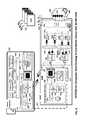
- FIGS. 5A-Care detailed hardware block diagrams of a wireless access point (WAP) showing alternate embodiments of the invention for generating a composite beam for downlink communications including a primary beam specified by the primary beam coordinator and secondary beam determined by each WAP.
- WAPwireless access point
- FIG. 5Ais a detailed hardware block diagram of the transmit portion of a WAP which includes an electronically steerable phased array coupled between the antenna 550 A-H and the radio frequency stage 530 for generating the steerable primary beam specified by the primary beam coordinator.
- the number of antennase.g. “8”, is significantly greater than the number of chains, e.g. “4”.
- the WAP 330 in this embodiment of the inventionincludes a wired Local Area Network (LAN) interface for coupling the WLAN stage 520 to the Internet and to the primary beam coordinator via a packet based bus 504 .
- the WLAN stageincludes a baseband portion 522 , a radio frequency portion 530 , and an electronically steerable or spatially selectable primary beam module 540 coupled to the MIMO antennas 550 A-H.
- LANLocal Area Network
- the WLAN stagesupports 4 chains each capable of handling different data.
- the baseband componentsinclude encoder and mappers 524 A-D each coupled to the spatial mapper 526 for frequency domain mapping of the secondary beam patterns onto the data transmitted on each tone or sub-channel.
- the transmitted data of each chainis converted from the frequency to the time domain in the Inverse Discrete Fourier Transform modules (IDFT) 528 A-D and presented to the RF stage 530 .
- IDFTInverse Discrete Fourier Transform modules
- each chainis subject to a digital-to-analog conversion (DAC) in DACs 532 A-D and subsequent upconversion in upconverters 536 A-D.
- DACdigital-to-analog conversion
- upconvertersare driven by a common oscillator 534 .
- Next each upconverted transmit chainis input to the primary beam module.
- the cross fabric switch 541 at the input thereofcouples each of the four chains to each of the eight antennas in discrete antenna drivers 542 A-H.
- Each driverallows adjustment of the phases and amplitudes of each of the four chains input via mixer to each antenna.
- Antenna driver 542 Aincludes phase adjusters 544 A-D coupled to power amplifiers 546 A-D the outputs of which are combined in mixer 548 A which is coupled to the associated one of the MIMO phased array antenna 550 A.
- the composite beamis generated from the superposition of the primary beams beamsteering matrix “B” and the secondary beams beamsteering matrices “P”.
- the slow varying frequency independent primary beamsteering matrix 543 “B”is used to drive the phase and amplitude adjustments of the primary beam module.
- the frequency dependent fast varying secondary beam(s)are generated with the secondary sub-channel beamsteering matrix “P”.
- the primary beam servo 506couples via the packet bus 504 to the primary beam module to control its operations using the primary beam setup options from the primary beam controller.
- the primary beam servois shown with an associated memory storage 518 which may be used to store the primary beam setup options 519 downloaded from the primary beam coordinator.
- the primary beam servo moduleis coupled to a primary beam coordinator via the primary beam coordinator interface 508 .
- the primary beam servo moduleis configured to accept therefrom spatially distinct primary beam pattern setup options and to select therefrom a corresponding one of the primary beam options together with its associated stations and to generate the corresponding selected primary beam option for subsequent downlink communications to at least one of the associated subset of stations; thereby increasing a downlink throughput of the WLAN via non-interfering concurrent downlink communications from each of the plurality of WAPs.
- the primary beam servoalso includes: a link and crosslink monitor 516 , a notifier 510 , a primary beam mode selector 512 , and a primary beam driver 514 .
- the link and crosslink monitor 516monitors channel state information (CSI) for communication links and crosslinks between each WAP node and both associated and non-associated station nodes thereof.
- the notifier 510is operative during initiation of a downlink to notify remaining ones of the plurality of WAPs of at least one of: the primary beam and station nodes associated with the downlink, and spatially distinct primary beams and associated stations compatible therewith, thereby avoiding a requirement for contact with the primary beam coordinator.
- the primary beam mode selector 512is operative in an initiator mode to gain initial access to the WLAN for a selected downlink to an associated at least one target station node via a first primary beam identified by the primary beam coordinator, and operative in a follower mode to gain subsequent access to the WLAN and to asynchronously initiate a concurrent WLAN downlink to another at least one associated target station node using another primary beam identified by the primary beam coordinator which is spatially distinct from the primary beam utilized by another one of the plurality of WAPs operative as an initiator for its discrete downlink.
- the primary beam mode selectoris also operative to generate a one primary beam pattern specified by the primary beam coordinator for downlink communications to the stations associated therewith, and in a follower mode to choose a subset of spatially distinct primary beam pattern setup options which are identified in the options as spatially consistent with the primary beam pattern selected by an initiating one of the WAPs for subsequent downlink communications to at least one of the associated station nodes; thereby allowing downlink follower WAPs to restrictively select downlink primary beam patterns from an identifiable subset of the setup options based on relative downlink demand between associated stations.
- the primary beam driverhandles the setup of the primary beam module 540 .
- FIG. 5Bis a detailed hardware block diagram of the transmit portion of an alternate-embodiment of a WAP which includes electronically steerable parasitic antennas (ESPAR) coupled with a primary beam module 560 between the radio frequency stage 530 and the four parasitic antennas 566 A-D. There is one steerable parasitic antenna for each chain. Each parasitic antenna includes a driven element 567 and parasitic elements 568 for shaping the resultant beam under control of the electronically tunable reactances in each antenna driver 562 A-D.
- the primary beam matrix “B”is used to drive the Primary beam module and the secondary beam matrix “P” is used to drive the spatial mapping of each tone in the spatial mapper 525 .
- FIG. 5Cis a detailed hardware block diagram of the transmit portion of an alternate embodiment of a WAP which includes a WAP with antennas 572 A-D driven by power amplifiers 570 A-D coupled to the aforesaid remaining RF components and baseband components discussed above.
- the number of streams of datamust be less then the number of chains in a configuration commonly referred to as massive MIMO configuration.
- the beamforming matrixis obtained at the baseband as the product of two matrices: “B” that depends on slowly-varying channel effects that are constant over time and frequency and “P” that depends on the instantaneous channel state information and that can depend on frequency.
- FIG. 6is a hardware block diagram at a system level of both a server 302 incorporating a primary beam coordinator 674 coupled to all WAPs 330 and 648 via a wired LAN connection 303 and the primary beam servo, e.g. servo 600 in WAP 303 .
- the WAP 330includes in this embodiment of the invention a LAN interface 618 coupled via a packet bus 620 to the WLAN stage 621 .
- the transmit and receive path components of the WLAN stageare shown.
- the transmit path componentsinclude encoder mappers 624 and spatial mapper 628 .
- the spatial mapperis driven with the secondary beamsteering matrix “P”.
- the output of each chainis converted from the frequency to the time domain by an associate IDFT 630 A-B.
- the output of the IDFTis input to the RF stage 632 for up conversion and input to the primary beam module 634 . That module accepts input of the primary beam's beamsteering matric 636 “B”.
- the primary beam moduleis coupled to phased array antennas 638 to transmit downlink communications over WLAN 640 to associated stations e.g. station 346 C.
- received communicationsare passed from the primary beam module to the RF module for down conversion.
- the received communicationsare transformed from the time to the frequency domain in the discrete Fourier transform (DFT) components 734 A-B.
- DFTdiscrete Fourier transform
- the received communications on each toneare then equalized in the equalizer and demapped and decoded in the demapper and decoder component 626 .
- a microprocessor 612is shown with associated memory 614 for storing the primary beam setup options 616 downloaded from the primary beam coordinator. The microprocessor is used to instantiate the primary beam servo 600 .
- the primary beam servoincludes: the primary beam coordinator interface 602 , the link and crosslink monitor 610 , the notifier 604 , the primary beam mode selector 606 and the primary beam driver 608 .
- the primary beam servoperforms identically to the modules discussed above in connection with FIG. 5A .
- the server 302is coupled to each WAP via the wired LAN connection 303 .
- the serverincludes microprocessor 650 and memory 652 for storing the correlated primary beam coordination tables 519 .
- the serverincludes a bus 654 coupling the microprocessor to read-only memory 656 , main memory 658 , a network interface 670 , and input ⁇ output device (I/O) interface 672 for interfacing with a keyboard and display for example.
- I/Oinput ⁇ output device
- the primary beam coordinatormay be instantiated via the microprocessor 650 . It includes the WAP interface 676 the link aggregator 678 , the cross correlator 680 for Primary beams and associated stations and links, and the distributor 682 for distributing primary beam options.
- the cross correlatoris used to correlate from the uploaded CSI information for communication links and crosslinks between each WAP node and both associated and non-associated station nodes thereof and extrapolate therefrom spatially distinct primary beam pattern setup options to each of the plurality of WAP nodes which enable substantially non-interfering concurrent downlink communications between each WAP node and a corresponding subset of its associated station nodes within each associated spatially distinct primary beam.
- FIGS. 7A-Bare process flow diagrams of the processes associated with coordinating concurrent WLAN links on both the primary beam coordinator coupled to all WAPs and the primary beam servo in each WAP, in accordance with an embodiment of the current invention.
- FIG. 7Ais the process flow diagram for each WAP's primary beam servo. Processing begins with the next link determination 700 . If the next link is an uplink control passes to process 710 . In process 710 the WAP monitors link and crosslink Channel State Information (CSI) from links of associated stations and from crosslinks from unassociated stations sharing the same WiFi channel as WAP. The WAP monitors slow varying semi-stable frequency independent channel characteristics such as signal strength or covariance Matrix [B] which will be used to evaluate primary beam patterns. Next in process 712 the monitored information from process 710 is uploaded to the Primary Beam Coordinator. Control then returns to decision process 700 .
- CSIChannel State Information
- decision process 720a determination is made as to whether the WAP is currently operative as an initiator who consistent with the CSMA ⁇ CA protocol has gained access to the channel or is a follower whose access to the channel is “blocked”. If a determination is made that the WAP is currently operative as an initiator then control passes to process 722 . In process 722 the WAP obtains the identifiable Primary Beam Setup Options for its target downlink station(s). In a reactive embodiment of the invention this may involve a request to the primary beam coordinator for download of the relevant primary beam setup options.
- the WAPidentifies that it already has a valid set of primary beam setup options previously downloaded from the primary beam coordinator.
- controlis passed to process 724 in which the WAP selects one of the primary beam options available to it for whichever station target(s) it wishes to downlink.
- the WAPgenerates a composite beam for the selected downlink including: the identified primary beam for the target station(s) and superimposed thereon whatever secondary beams are determined from channel soundings.
- Controlis then passed to process 728 . If notification to the primary beam coordinator is required as to which among the primary beam options was selected and what the downlink stations are, then that notification is performed in this step.
- a notificationmay be made by the WAP directly to follower WAPs as to which primary beam was selected by the WAP or alternately which primary beams should be selected by the followers. In any event, control then returns to decision process 700 for the processing of the next link.
- process 730the WAP obtains identifiable non-interfering primary beam setup options and associated prospective target station(s) from the primary beam controller by lookup of options previously downloaded therefrom.
- Controlis then passed to process 732 in which the WAP selects one of the non-interfering primary beam option(s) and associated target station(s) for downlink.
- the WAPgenerates the composite beam for the downlink including: a selected non-interfering primary beam for the associated target station(s) and superimposes that with the secondary beam(s) determined by channel soundings of the downlink. Control then returns to decision process 700 for the processing of the next link.
- FIG. 7Bis the process flow diagram for the server's primary beam coordinator. Processing begins with process 750 in which the primary beam coordinator aggregates the primary beam coordination data from WAPs for each link and crosslink to associated and unassociated station nodes. Next in process 752 the primary beam coordinator identifies for the CSMA initiator WAP the optimal primary beam pattern or shapes for the requested downlink target station(s). Control then passes to process 754 in which each primary beam and subset of associated stations for each initiator WAP is cross correlated with associated primary beam pattern(s) and downlink station(s) candidates for remaining follower WAPs on the WLAN grid sharing the same channel. Then control passes to process 756 for dissemination of primary beam setup options and associated parameters to the initiator WAP and all follower WAPs. Control then returns to process 750 .
- x[t,f]is the M-dimensional signal vector (complex I-Q coefficients) at OFDM symbol t, subcarrier f
- Vis the beamforming matrix for OFDM subcarrier f, constant over a frame of N OFDM symbols
- dis the S-dimensional information data vector (each component is a QAM modulation symbol to be transmitted at OFDM symbol t, subcarrier f.)
- the fundamental information about the channel statistics needed to compute B in the case of an antenna arrayis the channel sample covariance matrix, given by:
- the sample covariance matrixcan be obtained from a sufficiently large number m of quadratic projections, r i , in the form:
- the received signal powertakes again the form:
Landscapes
- Engineering & Computer Science (AREA)
- Computer Networks & Wireless Communication (AREA)
- Signal Processing (AREA)
- Mobile Radio Communication Systems (AREA)
Abstract
Description
x[t,f], t=1, 2, . . . , N
is transmitted over N OFDM symbols forming a slot (frame) from the M base station antennas. The beamforming matrix V is a function of the instantaneous Channel State Information (CSI), that changes from frame to frame and it is estimated via the uplink pilot signals. Specifically
x[t,f]=V[f]d[t,f], t=1,2, . . . ,N
where x[t,f] is the M-dimensional signal vector (complex I-Q coefficients) at OFDM symbol t, subcarrier f, V is the beamforming matrix for OFDM subcarrier f, constant over a frame of N OFDM symbols, and d is the S-dimensional information data vector (each component is a QAM modulation symbol to be transmitted at OFDM symbol t, subcarrier f.)
x[t,f]=BP[f]d[t,f], t=1, . . . , N
Since B is constant in frequency, it can be implemented in the time domain in the analog RF front end, either by a phased array or, under some constraints, through a set of reconfigurable beam-steering parasitic antennas.
Brief Description of Estimation of Slow Statistics
This can be obtained by estimating uplink channels from uplink pilot signals, and computing the above arithmetic mean summing both over time (frames) and over frequency (subcarriers) where T is the number of frames, F the number of subcarriers, and h is the channel matrix.
using appropriately defined “test vectors” ai, i=1 . . . m.
where now ai, i=1 . . . m, denotes the possible beam configurations of the ESPAR.
Claims (12)
Priority Applications (1)
| Application Number | Priority Date | Filing Date | Title |
|---|---|---|---|
| US14/612,293US9479240B1 (en) | 2014-01-31 | 2015-02-02 | Composite beamforming to coordinate concurrent WLAN links |
Applications Claiming Priority (3)
| Application Number | Priority Date | Filing Date | Title |
|---|---|---|---|
| US201461934147P | 2014-01-31 | 2014-01-31 | |
| US201461996096P | 2014-04-29 | 2014-04-29 | |
| US14/612,293US9479240B1 (en) | 2014-01-31 | 2015-02-02 | Composite beamforming to coordinate concurrent WLAN links |
Publications (1)
| Publication Number | Publication Date |
|---|---|
| US9479240B1true US9479240B1 (en) | 2016-10-25 |
Family
ID=57136619
Family Applications (1)
| Application Number | Title | Priority Date | Filing Date |
|---|---|---|---|
| US14/612,293Active2035-05-08US9479240B1 (en) | 2014-01-31 | 2015-02-02 | Composite beamforming to coordinate concurrent WLAN links |
Country Status (1)
| Country | Link |
|---|---|
| US (1) | US9479240B1 (en) |
Cited By (6)
| Publication number | Priority date | Publication date | Assignee | Title |
|---|---|---|---|---|
| US9647736B1 (en)* | 2015-03-05 | 2017-05-09 | Quantenna Communications, Inc. | Compressed training for massive MU-MIMO in a wireless local area network |
| US9743333B1 (en) | 2017-04-01 | 2017-08-22 | Quantenna Communications, Inc. | Arbitration of distributed services for wireless home networks |
| CN107579568A (en)* | 2017-07-27 | 2018-01-12 | 金虎林 | Utilize the wireless charging system of Beamforming antennas |
| US20190013983A1 (en)* | 2016-10-31 | 2019-01-10 | Southeast University | Systems and methods for wireless communication with per-beam signal synchronization |
| US10491288B2 (en)* | 2015-11-05 | 2019-11-26 | Sony Corporation | Wireless communication method and wireless communication device |
| US11399391B2 (en)* | 2018-02-14 | 2022-07-26 | Guangdong Oppo Mobile Telecommunications Corp., Ltd. | Method and device to provide a signal transmission between a sending node and receiving node in unlicensed frequency band |
Citations (38)
| Publication number | Priority date | Publication date | Assignee | Title |
|---|---|---|---|---|
| US5839053A (en) | 1995-08-02 | 1998-11-17 | Agence Spatiale Europeene | System for transmitting radio signals from mobile terminals to provide space diversity for uplink signals via geostationary communication satellites |
| US20020138511A1 (en) | 2001-03-23 | 2002-09-26 | Konstantinos Psounis | Method and system for class-based management of dynamic content in a networked environment |
| EP1447934A1 (en) | 2003-02-12 | 2004-08-18 | Institut Eurecom G.I.E. | Transmission and reception diversity process for wireless communications |
| EP1447936A1 (en) | 2003-02-11 | 2004-08-18 | Motorola Inc. | Data communication unit and method thereof for iterative decoding |
| US20060040707A1 (en) | 2004-08-18 | 2006-02-23 | Video54 Technologies, Inc. | System and method for transmission parameter control for an antenna apparatus with selectable elements |
| US7324442B1 (en) | 2000-02-28 | 2008-01-29 | The Board Of Trustees Of The Leland Stanford Junior University | Active queue management toward fair bandwidth allocation |
| US20090185607A1 (en) | 2008-01-22 | 2009-07-23 | Electronics And Telecommunications Research Institute | Method for channel state feedback by quantization of time-domain coefficients |
| US20100041408A1 (en) | 2008-08-15 | 2010-02-18 | Giuseppe Caire | Method for varying transmit power patterns in a multi-cell environment |
| US20100041407A1 (en) | 2008-08-13 | 2010-02-18 | Giuseppe Caire | Method of combined user and coordination pattern scheduling over varying antenna and base-station coordination patterns in a multi-cell environment |
| US20100040163A1 (en) | 2008-08-15 | 2010-02-18 | Giuseppe Caire | Channel classification and rate adaptation for su-mimo systems |
| US20100040006A1 (en) | 2008-08-13 | 2010-02-18 | Giuseppe Caire | Variable coordination pattern approach for improving performance in multi-cell or multi-antenna environments |
| US20100159930A1 (en)* | 2008-12-23 | 2010-06-24 | Bo Hagerman | Base station and method for vertical tilt antenna beam sweeping |
| US20100322327A1 (en) | 2009-06-23 | 2010-12-23 | Giuseppe Caire | Method of estimating and removing noise in OFDM systems |
| US20110002373A1 (en)* | 2008-03-11 | 2011-01-06 | Lg Electronics Inc. | Apparatus for performing beam tracking process and method thereof |
| US20110032849A1 (en)* | 2009-08-07 | 2011-02-10 | Fimax Technology Limited | Systems and methods for mitigating interference between access points |
| US20110110449A1 (en) | 2009-05-05 | 2011-05-12 | Ramprashad Sean A | Receiver terminal driven joint encoder and decoder mode adaptation for su-mimo systems |
| US20120039385A1 (en) | 2010-06-18 | 2012-02-16 | Ozgun Bursalioglu Yilmaz | System and method for lossy source-channel coding at the application layer |
| US20120113953A1 (en) | 2010-11-04 | 2012-05-10 | Haralabos Papadopoulos | Method and apparatus for the joint design and operation of scheduling and transmission for downlink multi-user mimo with reciprocity-based training |
| US20120127869A1 (en)* | 2010-11-22 | 2012-05-24 | Sharp Laboratories Of America, Inc. | Multiple channel state information (csi) reporting on the physical uplink shared channel (pusch) with carrier aggregation |
| US20130273950A1 (en) | 2011-01-10 | 2013-10-17 | Alcatel Lucent | Interference suppression method and apparatus in multi-point coordinated transmission system |
| WO2013176962A1 (en) | 2012-05-25 | 2013-11-28 | University Of Southern California | Airsync: enabling distributed multiuser mimo with full multiplexing gain |
| US20130331136A1 (en) | 2012-06-07 | 2013-12-12 | Kai Yang | Method And Apparatus For Coordinated Beamforming |
| US20130336270A1 (en)* | 2011-01-07 | 2013-12-19 | Ntt Docomo, Inc. | Radio base station apparatus, user terminal and radio communication method |
| US20140044041A1 (en)* | 2012-08-08 | 2014-02-13 | Golba Llc | Method and system for distributed transceivers for distributed access points connectivity |
| WO2014039098A1 (en) | 2012-09-04 | 2014-03-13 | Ntt Docomo, Inc. | Method and apparatus for internal relative transceiver calibration |
| US8675511B2 (en) | 2008-12-10 | 2014-03-18 | Qualcomm Incorporated | List elimination for distributed downlink coordinated multi-point (CoMP) framework |
| US20140094164A1 (en) | 2012-09-28 | 2014-04-03 | Qualcomm Incorporated | Iterative coordinated beamforming systems and methods |
| US20140113600A1 (en) | 2010-09-28 | 2014-04-24 | The Ohio State University | Predictive network system and method |
| US20140211779A1 (en) | 2013-01-31 | 2014-07-31 | University Of Southern California | Scalable synchronization for distributed multiuser mimo |
| US8824330B2 (en) | 2008-08-08 | 2014-09-02 | Furturewei Technologies, Inc. | System and method for synchronized and coordinated beam switching and scheduling in a wireless communications system |
| US20140362810A1 (en) | 2009-08-26 | 2014-12-11 | Hooman Shirani-Mehr | Method and apparatus for the joint design and operation of arq protocols with user scheduling for use with multiuser mimo in the downlink of wireless systems |
| US20150071368A1 (en)* | 2013-09-09 | 2015-03-12 | The Hong Kong University Of Science And Technology | Csi feedback reduction for mimo interference alignment |
| US20150110046A1 (en)* | 2013-10-17 | 2015-04-23 | Qualcomm Incorporated | Methods and apparatus for channel state information feedback |
| US20150124732A1 (en)* | 2012-05-15 | 2015-05-07 | Lg Electronics Inc. | Method for receiving downlink data, method for transmitting downlink data to user equipment, and base station |
| US20150124688A1 (en)* | 2013-11-04 | 2015-05-07 | Samsung Electronics Co., Ltd. | Multistage beamforming of multiple-antenna communication system |
| US9078153B1 (en)* | 2014-10-31 | 2015-07-07 | Quantenna Communications, Inc. | Wireless local area network with spatial diagnostics |
| US20160037560A1 (en)* | 2014-07-29 | 2016-02-04 | Futurewei Technologies, Inc. | Device, Network, and Method for Communications with Spatial-specific Sensing |
| US20160127019A1 (en)* | 2014-10-31 | 2016-05-05 | Quantenna Communications, Inc. | Unsolicited Channel Sounding in a Wireless Local Area Network |
- 2015
- 2015-02-02USUS14/612,293patent/US9479240B1/enactiveActive
Patent Citations (40)
| Publication number | Priority date | Publication date | Assignee | Title |
|---|---|---|---|---|
| US5839053A (en) | 1995-08-02 | 1998-11-17 | Agence Spatiale Europeene | System for transmitting radio signals from mobile terminals to provide space diversity for uplink signals via geostationary communication satellites |
| US7324442B1 (en) | 2000-02-28 | 2008-01-29 | The Board Of Trustees Of The Leland Stanford Junior University | Active queue management toward fair bandwidth allocation |
| US20020138511A1 (en) | 2001-03-23 | 2002-09-26 | Konstantinos Psounis | Method and system for class-based management of dynamic content in a networked environment |
| EP1447936A1 (en) | 2003-02-11 | 2004-08-18 | Motorola Inc. | Data communication unit and method thereof for iterative decoding |
| EP1447934A1 (en) | 2003-02-12 | 2004-08-18 | Institut Eurecom G.I.E. | Transmission and reception diversity process for wireless communications |
| US20060040707A1 (en) | 2004-08-18 | 2006-02-23 | Video54 Technologies, Inc. | System and method for transmission parameter control for an antenna apparatus with selectable elements |
| US20090185607A1 (en) | 2008-01-22 | 2009-07-23 | Electronics And Telecommunications Research Institute | Method for channel state feedback by quantization of time-domain coefficients |
| US20110002373A1 (en)* | 2008-03-11 | 2011-01-06 | Lg Electronics Inc. | Apparatus for performing beam tracking process and method thereof |
| US8824330B2 (en) | 2008-08-08 | 2014-09-02 | Furturewei Technologies, Inc. | System and method for synchronized and coordinated beam switching and scheduling in a wireless communications system |
| US20100041407A1 (en) | 2008-08-13 | 2010-02-18 | Giuseppe Caire | Method of combined user and coordination pattern scheduling over varying antenna and base-station coordination patterns in a multi-cell environment |
| US20100040006A1 (en) | 2008-08-13 | 2010-02-18 | Giuseppe Caire | Variable coordination pattern approach for improving performance in multi-cell or multi-antenna environments |
| US8472963B2 (en) | 2008-08-13 | 2013-06-25 | Ntt Docomo, Inc. | Variable coordination pattern approach for improving performance in multi-cell or multi-antenna environments |
| US20100040163A1 (en) | 2008-08-15 | 2010-02-18 | Giuseppe Caire | Channel classification and rate adaptation for su-mimo systems |
| US20100041408A1 (en) | 2008-08-15 | 2010-02-18 | Giuseppe Caire | Method for varying transmit power patterns in a multi-cell environment |
| US8675511B2 (en) | 2008-12-10 | 2014-03-18 | Qualcomm Incorporated | List elimination for distributed downlink coordinated multi-point (CoMP) framework |
| US20100159930A1 (en)* | 2008-12-23 | 2010-06-24 | Bo Hagerman | Base station and method for vertical tilt antenna beam sweeping |
| US20110110449A1 (en) | 2009-05-05 | 2011-05-12 | Ramprashad Sean A | Receiver terminal driven joint encoder and decoder mode adaptation for su-mimo systems |
| US20100322327A1 (en) | 2009-06-23 | 2010-12-23 | Giuseppe Caire | Method of estimating and removing noise in OFDM systems |
| US20110032849A1 (en)* | 2009-08-07 | 2011-02-10 | Fimax Technology Limited | Systems and methods for mitigating interference between access points |
| US20140362810A1 (en) | 2009-08-26 | 2014-12-11 | Hooman Shirani-Mehr | Method and apparatus for the joint design and operation of arq protocols with user scheduling for use with multiuser mimo in the downlink of wireless systems |
| US20120039385A1 (en) | 2010-06-18 | 2012-02-16 | Ozgun Bursalioglu Yilmaz | System and method for lossy source-channel coding at the application layer |
| US20140113600A1 (en) | 2010-09-28 | 2014-04-24 | The Ohio State University | Predictive network system and method |
| US20120113953A1 (en) | 2010-11-04 | 2012-05-10 | Haralabos Papadopoulos | Method and apparatus for the joint design and operation of scheduling and transmission for downlink multi-user mimo with reciprocity-based training |
| US8638746B2 (en) | 2010-11-04 | 2014-01-28 | Ntt Docomo, Inc. | Method and apparatus for the joint design and operation of scheduling and transmission for downlink multi-user MIMO with reciprocity-based training |
| US20120127869A1 (en)* | 2010-11-22 | 2012-05-24 | Sharp Laboratories Of America, Inc. | Multiple channel state information (csi) reporting on the physical uplink shared channel (pusch) with carrier aggregation |
| US20130336270A1 (en)* | 2011-01-07 | 2013-12-19 | Ntt Docomo, Inc. | Radio base station apparatus, user terminal and radio communication method |
| US20130273950A1 (en) | 2011-01-10 | 2013-10-17 | Alcatel Lucent | Interference suppression method and apparatus in multi-point coordinated transmission system |
| US20150124732A1 (en)* | 2012-05-15 | 2015-05-07 | Lg Electronics Inc. | Method for receiving downlink data, method for transmitting downlink data to user equipment, and base station |
| WO2013176962A1 (en) | 2012-05-25 | 2013-11-28 | University Of Southern California | Airsync: enabling distributed multiuser mimo with full multiplexing gain |
| US20130331136A1 (en) | 2012-06-07 | 2013-12-12 | Kai Yang | Method And Apparatus For Coordinated Beamforming |
| US20140044041A1 (en)* | 2012-08-08 | 2014-02-13 | Golba Llc | Method and system for distributed transceivers for distributed access points connectivity |
| WO2014039098A1 (en) | 2012-09-04 | 2014-03-13 | Ntt Docomo, Inc. | Method and apparatus for internal relative transceiver calibration |
| US20140094164A1 (en) | 2012-09-28 | 2014-04-03 | Qualcomm Incorporated | Iterative coordinated beamforming systems and methods |
| US20140211779A1 (en) | 2013-01-31 | 2014-07-31 | University Of Southern California | Scalable synchronization for distributed multiuser mimo |
| US20150071368A1 (en)* | 2013-09-09 | 2015-03-12 | The Hong Kong University Of Science And Technology | Csi feedback reduction for mimo interference alignment |
| US20150110046A1 (en)* | 2013-10-17 | 2015-04-23 | Qualcomm Incorporated | Methods and apparatus for channel state information feedback |
| US20150124688A1 (en)* | 2013-11-04 | 2015-05-07 | Samsung Electronics Co., Ltd. | Multistage beamforming of multiple-antenna communication system |
| US20160037560A1 (en)* | 2014-07-29 | 2016-02-04 | Futurewei Technologies, Inc. | Device, Network, and Method for Communications with Spatial-specific Sensing |
| US9078153B1 (en)* | 2014-10-31 | 2015-07-07 | Quantenna Communications, Inc. | Wireless local area network with spatial diagnostics |
| US20160127019A1 (en)* | 2014-10-31 | 2016-05-05 | Quantenna Communications, Inc. | Unsolicited Channel Sounding in a Wireless Local Area Network |
Non-Patent Citations (30)
| Title |
|---|
| A. Adhikary et al.; "Joint Spatial Division and Multiplexing for mm-Wave Channels"; IEEE Journal on Selected Areas in Communications, vol. 32, No. 6, Jun. 2014. |
| A. Adhikary et al.;"Joint Spatial Division and Multiplexing-The Large Scale Array Regime"; IEEE Transactions on Information Theory, vol. 59, No. 10, Oct. 2013. |
| A. Farajidana, et al.; "3GPP LTE Downlink System Performance", IEEE Globcom 2009. |
| A. Michaloliakos et al.;"Efficient MAC for Distributed Multiuser MIMO Systems"; Wireless On-Demand Network Systems and Services (WONS), 2013 10th Annual Converence on, Mar. 2013, Banff AB Canada. |
| E. J. Candes et al.; "Exact Matrix Completion via Convex Optimization"; Foundation of Computational Mathematics (2009) 9:717-772. |
| G. Caire et al.; "On the Achievable Throughput of a MultiAntenna Gaussian Broadcast Channel"; IEEE Transactions on Information Theory, vol. 49, No. 7, Jul. 2003. |
| H. Huh et al.; "Achieving 'Massive MIMO' Spectral Efficiency with a Not-so-Large Numer of Antennas"; IEEE Transactions on Wireless Communications, vol. 11, No. 9, Sep. 2012. |
| H. Rahul et al.; "JMB: Scaling Wireless Capacity with User Demands"; SIGCOMM'12 Helsinki Finland Aug. 2012. |
| H. V. Balan et al.; "Achieving High Data Rates in a Distributed MIMO System"; MobiCom '12 Autust 2012 Istanbul, Turkey. |
| H. V. Balan et al.; "Air Sync: Enabling Distributed Multiuser MIMO with Full Spatial Multiplexing"; IEEE ACM Transactions on Networking, 2012. |
| H. Weingarten et al.; "The Capacity Region of the Gaussian Multiple-Input Multiple-Output Broadcast Channel" IEEE Transactions on Information Theory, vol. 52, No. 9, Sep. 2006. |
| H. Yang et al.; "Performance of Conjugate and Zero-Forcing Beamforming in Large-Scale Antenna Systems"; IEEE Journal on Selected Areas in Communications, vol. 31, No. 2, Feb. 2003. |
| H.V . Balan et al.; "USC SDR, an Easy-to-Program, High Data Rate, Real Time Software Radio Platform"; SRIF'13 Aug. 2013 Hong Kong, China. |
| J. He et al.; "Online Robust Subspace Tracking from Partial Information"; arXiv:1109 .3827v2 [cs.IT] Sep. 2011. |
| J. Hoydis et al.; "Massive MIMO in the UL/DL of Cellular Networks: How Many Antennas do we Need?"; IEEE Journal on Selected Areas in Communications, vol. 31, No. 2, Feb. 2013. |
| J. Jose et al.; "Pilot Contamination and Precoding in Multi-Cell TDD Systems"; IEEE Transactions on Wireless Communications, vol. 10; No. 8 Aug. 2011. |
| J. Nam et al.; "Joint Spatial Division and Multiplexing: Opportunistic Beamforming, User Grouping and Simplified Downlink Scheduling" IEEE Journal of Selected Topics in Signal Processing, vol. 8, No. 5, Oct. 2014. |
| J. Nam et al.; "Joint Spatial Division and Multiplexing-: Realizing Massive MIMO Gains with Limited Channel State Information"; Information Sciences and Systems (CISS), 2012 46th Annual Conference on Mar. 2012. |
| JB Landre et al.; "Realistic Performance of HSDPA MIMO in Macro-Cell Environment"; Personal, Indoor and Mobile Radio Communications, 2009 IEEE 20th International Symposium on Sep. 2009, Tokyo. |
| L. Balzano et al.; "Online Identification and Tracking of Subspaces from Highly Incomplete Information"; arXiv:1006 .4046v2 [cs.IT] Jul. 2011. |
| P. Viswanath, et al.; "Sum Capacity of the Vector Gaussian Broadcast Channel and Uplink-Downlink Duality"; IEEE Transactions on Information Theory, vol. 49, No. 8 Aug. 2003. |
| S. Kumar et al.; "Bringing Cross-Layer MIMO to Today's Wirless LANs"; SIGCOMM Hong Kong, China, Aug. 2013. |
| S. Parkvall et al.; "LTE-Advanced-Evolving LTE towards IMT-Advanced"; Vehicular Technology Converence, 2008 VTC 2008-Fall. IEEE 68th Calbary BC Canada. |
| S. Vishwanath et al.;"Duality, Achievable Rates, and Sum-Rate Capacity of Gaussian MIMO Broadcast Channels"; IEEE Transactions on Information Theory, vol. 49, No. 10 Oct. 2003. |
| T. L. Marzetta; "Noncooperative Cellular Wireless with Unlimited Numbers of Base Station Antennas"; IEEE Transactions on Wireless Communications, vol. 9, No. 11, Nov. 2010. |
| W. Yu et al.; "Sum Capacity of Gaussian Vector Broadcast Channels"; IEEE Transactions on Information Theory, vol. 50, No. 9, Sep. 2004. |
| X. Liu et al.; "DIRC: Increasing Indoor Wireless Capacity using Directional Antennas"; SIGCOMM '09 Barcelona, Spain, Aug. 2009. |
| X. Zhang et al.; "NEMOx: Scalable Network MIMO for Wireless Networks"; MobiCom '13 Sep. 2013 Miami Florida. |
| Y. Chen et al.;"Exact and Stable Covariance Estimation from Quadratic Sampling via Convex Programming"; arXiv:1310. 0807v4 [cs.IT], Dec. 2013. |
| Z. Tan et al.;"Direction of Arrival Estimation Using Co-Prime Arrays: A Super Resolution Viewpoint"; arXiv:1312. 7793v1 [cs.IT], Dec. 2013. |
Cited By (8)
| Publication number | Priority date | Publication date | Assignee | Title |
|---|---|---|---|---|
| US9647736B1 (en)* | 2015-03-05 | 2017-05-09 | Quantenna Communications, Inc. | Compressed training for massive MU-MIMO in a wireless local area network |
| US10491288B2 (en)* | 2015-11-05 | 2019-11-26 | Sony Corporation | Wireless communication method and wireless communication device |
| US10637554B2 (en)* | 2015-11-05 | 2020-04-28 | Sony Corporation | Wireless communication method and wireless communication device |
| US20190013983A1 (en)* | 2016-10-31 | 2019-01-10 | Southeast University | Systems and methods for wireless communication with per-beam signal synchronization |
| US10541850B2 (en)* | 2016-10-31 | 2020-01-21 | Southeast University | Systems and methods for wireless communication with per-beam signal synchronization |
| US9743333B1 (en) | 2017-04-01 | 2017-08-22 | Quantenna Communications, Inc. | Arbitration of distributed services for wireless home networks |
| CN107579568A (en)* | 2017-07-27 | 2018-01-12 | 金虎林 | Utilize the wireless charging system of Beamforming antennas |
| US11399391B2 (en)* | 2018-02-14 | 2022-07-26 | Guangdong Oppo Mobile Telecommunications Corp., Ltd. | Method and device to provide a signal transmission between a sending node and receiving node in unlicensed frequency band |
Similar Documents
| Publication | Publication Date | Title |
|---|---|---|
| US9479240B1 (en) | Composite beamforming to coordinate concurrent WLAN links | |
| US12184360B2 (en) | User device beamforming training in wireless networks | |
| US10218478B2 (en) | Method for determining weight for beamforming in wireless communication system and apparatus therefor | |
| US11387959B2 (en) | WiFi antenna selection with beamforming | |
| US12206477B2 (en) | Hybrid sector selection and beamforming | |
| US10966220B2 (en) | Method and apparatus for scheduling, load balancing, and pilot-assignments in reciprocity-based MIMO cellular deployments | |
| US9271176B2 (en) | System and method for backhaul based sounding feedback | |
| US9467999B2 (en) | Base station configuration using massive multiple input multiple output (M-MIMO) | |
| US11876584B2 (en) | WAP uplink optimization by selection of MIMO antennas spatial states | |
| US20150270879A1 (en) | System and method for explicit channel sounding between access points | |
| KR20190016959A (en) | System and method for beamforming feedback in millimeter-wave wireless local area networks | |
| TW201840144A (en) | A method of wireless communication, an initiator device and a responder device | |
| US9941945B2 (en) | Method for performing mobility-based beamforming in wireless communication system, and apparatus therefor | |
| US20180145732A1 (en) | Methods and systems for multi-user beamforming | |
| CN110365460A (en) | Devices, networks and methods for communicating using space-specific sensing | |
| KR20140093446A (en) | Method and apparatus for transmitting channel state information reference signal and hybrid spatial mutiplexing and space division multiple access for wireless communication system using planar antenna array | |
| US11757518B2 (en) | Multi-level beam scheduling in a wireless communications circuit, particularly for a wireless communications system (WCS) | |
| US20180249506A1 (en) | Wap supporting complementary subnets in a wlan | |
| US10469151B2 (en) | Beam scanning method of terminal for hybrid beam forming in wireless communication system, and device for same | |
| US9992795B1 (en) | WAP supporting complementary subnets in a WLAN | |
| US10693528B1 (en) | Antenna array sharing in a multi-operator radio node in a communications system | |
| JP6812393B2 (en) | Heterogeneous multi-antenna system and how to operate it | |
| US20250056265A1 (en) | Interference reduction between wireless communication devices of overlapping basic service sets | |
| EP3782408B1 (en) | Multi-radio wireless transceiver power conservation | |
| US20160359606A1 (en) | Method and apparatus for interference alignment and multi-antenna signal process in wireless network |
Legal Events
| Date | Code | Title | Description |
|---|---|---|---|
| AS | Assignment | Owner name:QUANTENNA COMMUNICATIONS, INC., CALIFORNIA Free format text:ASSIGNMENT OF ASSIGNORS INTEREST;ASSIGNORS:CAIRE, GUISEPPE;PSOUNIS, KONSTANTINOS;SIGNING DATES FROM 20150212 TO 20150227;REEL/FRAME:035582/0863 | |
| AS | Assignment | Owner name:SILICON VALLEY BANK, CALIFORNIA Free format text:SECURITY AGREEMENT;ASSIGNOR:QUANTENNA COMMUNICATIONS, INC.;REEL/FRAME:038754/0371 Effective date:20160517 | |
| STCF | Information on status: patent grant | Free format text:PATENTED CASE | |
| AS | Assignment | Owner name:QUANTENNA COMMUNICATIONS, INC., CALIFORNIA Free format text:RELEASE BY SECURED PARTY;ASSIGNOR:SILICON VALLEY BANK;REEL/FRAME:049332/0372 Effective date:20190528 | |
| AS | Assignment | Owner name:DEUTSCHE BANK AG NEW YORK BRANCH, AS COLLATERAL AG Free format text:PATENT SECURITY AGREEMENT;ASSIGNOR:ON SEMICONDUCTOR CONNECTIVITY SOLUTIONS, INC.;REEL/FRAME:051426/0410 Effective date:20191220 Owner name:DEUTSCHE BANK AG NEW YORK BRANCH, AS COLLATERAL AGENT, NEW YORK Free format text:PATENT SECURITY AGREEMENT;ASSIGNOR:ON SEMICONDUCTOR CONNECTIVITY SOLUTIONS, INC.;REEL/FRAME:051426/0410 Effective date:20191220 | |
| MAFP | Maintenance fee payment | Free format text:PAYMENT OF MAINTENANCE FEE, 4TH YEAR, LARGE ENTITY (ORIGINAL EVENT CODE: M1551); ENTITY STATUS OF PATENT OWNER: LARGE ENTITY Year of fee payment:4 | |
| AS | Assignment | Owner name:ON SEMICONDUCTOR CONNECTIVITY SOLUTIONS, INC., CALIFORNIA Free format text:MERGER AND CHANGE OF NAME;ASSIGNORS:RAPTOR OPERATIONS SUB, INC.;QUANTENNA COMMUNICATIONS, INC.;REEL/FRAME:063271/0657 Effective date:20190619 Owner name:SEMICONDUCTOR COMPONENTS INDUSTRIES, LLC, ARIZONA Free format text:ASSIGNMENT OF ASSIGNORS INTEREST;ASSIGNOR:ON SEMICONDUCTOR CONNECTIVITY SOLUTIONS, INC.;REEL/FRAME:063280/0591 Effective date:20230406 | |
| AS | Assignment | Owner name:ON SEMICONDUCTOR CONNECTIVITY SOLUTIONS, INC., ARIZONA Free format text:RELEASE BY SECURED PARTY;ASSIGNOR:DEUTSCHE BANK AG NEW YORK BRANCH;REEL/FRAME:063516/0736 Effective date:20230501 | |
| AS | Assignment | Owner name:MAXLINEAR, INC., CALIFORNIA Free format text:ASSIGNMENT OF ASSIGNORS INTEREST;ASSIGNOR:SEMICONDUCTOR COMPONENTS INDUSTRIES, LLC;REEL/FRAME:063572/0701 Effective date:20230502 | |
| AS | Assignment | Owner name:ON SEMICONDUCTOR CONNECTIVITY SOLUTIONS, INC., AS GRANTOR, ARIZONA Free format text:RELEASE OF SECURITY INTEREST IN PATENTS, RECORDED AT REEL 051426, FRAME 0410;ASSIGNOR:DEUTSCHE BANK AG NEW YORK BRANCH, AS COLLATERAL AGENT;REEL/FRAME:064067/0340 Effective date:20230622 | |
| MAFP | Maintenance fee payment | Free format text:PAYMENT OF MAINTENANCE FEE, 8TH YEAR, LARGE ENTITY (ORIGINAL EVENT CODE: M1552); ENTITY STATUS OF PATENT OWNER: LARGE ENTITY Year of fee payment:8 |