US9477649B1 - Multi-layer telestration on a multi-touch display device - Google Patents
Multi-layer telestration on a multi-touch display deviceDownload PDFInfo
- Publication number
- US9477649B1 US9477649B1US12/652,632US65263210AUS9477649B1US 9477649 B1US9477649 B1US 9477649B1US 65263210 AUS65263210 AUS 65263210AUS 9477649 B1US9477649 B1US 9477649B1
- Authority
- US
- United States
- Prior art keywords
- display device
- annotation
- visual display
- input mechanism
- touch display
- Prior art date
- Legal status (The legal status is an assumption and is not a legal conclusion. Google has not performed a legal analysis and makes no representation as to the accuracy of the status listed.)
- Active, expires
Links
Images


Classifications
- G06F17/242—
- G—PHYSICS
- G06—COMPUTING OR CALCULATING; COUNTING
- G06F—ELECTRIC DIGITAL DATA PROCESSING
- G06F3/00—Input arrangements for transferring data to be processed into a form capable of being handled by the computer; Output arrangements for transferring data from processing unit to output unit, e.g. interface arrangements
- G06F3/01—Input arrangements or combined input and output arrangements for interaction between user and computer
- G06F3/048—Interaction techniques based on graphical user interfaces [GUI]
- G06F3/0484—Interaction techniques based on graphical user interfaces [GUI] for the control of specific functions or operations, e.g. selecting or manipulating an object, an image or a displayed text element, setting a parameter value or selecting a range
- G06F3/04845—Interaction techniques based on graphical user interfaces [GUI] for the control of specific functions or operations, e.g. selecting or manipulating an object, an image or a displayed text element, setting a parameter value or selecting a range for image manipulation, e.g. dragging, rotation, expansion or change of colour
- G—PHYSICS
- G06—COMPUTING OR CALCULATING; COUNTING
- G06F—ELECTRIC DIGITAL DATA PROCESSING
- G06F3/00—Input arrangements for transferring data to be processed into a form capable of being handled by the computer; Output arrangements for transferring data from processing unit to output unit, e.g. interface arrangements
- G06F3/01—Input arrangements or combined input and output arrangements for interaction between user and computer
- G06F3/048—Interaction techniques based on graphical user interfaces [GUI]
- G06F3/0487—Interaction techniques based on graphical user interfaces [GUI] using specific features provided by the input device, e.g. functions controlled by the rotation of a mouse with dual sensing arrangements, or of the nature of the input device, e.g. tap gestures based on pressure sensed by a digitiser
- G06F3/0488—Interaction techniques based on graphical user interfaces [GUI] using specific features provided by the input device, e.g. functions controlled by the rotation of a mouse with dual sensing arrangements, or of the nature of the input device, e.g. tap gestures based on pressure sensed by a digitiser using a touch-screen or digitiser, e.g. input of commands through traced gestures
- G06F3/04883—Interaction techniques based on graphical user interfaces [GUI] using specific features provided by the input device, e.g. functions controlled by the rotation of a mouse with dual sensing arrangements, or of the nature of the input device, e.g. tap gestures based on pressure sensed by a digitiser using a touch-screen or digitiser, e.g. input of commands through traced gestures for inputting data by handwriting, e.g. gesture or text
- G—PHYSICS
- G06—COMPUTING OR CALCULATING; COUNTING
- G06F—ELECTRIC DIGITAL DATA PROCESSING
- G06F40/00—Handling natural language data
- G06F40/10—Text processing
- G06F40/166—Editing, e.g. inserting or deleting
- G06F40/169—Annotation, e.g. comment data or footnotes
- G—PHYSICS
- G06—COMPUTING OR CALCULATING; COUNTING
- G06F—ELECTRIC DIGITAL DATA PROCESSING
- G06F40/00—Handling natural language data
- G06F40/10—Text processing
- G06F40/166—Editing, e.g. inserting or deleting
- G06F40/171—Editing, e.g. inserting or deleting by use of digital ink
- G—PHYSICS
- G06—COMPUTING OR CALCULATING; COUNTING
- G06V—IMAGE OR VIDEO RECOGNITION OR UNDERSTANDING
- G06V40/00—Recognition of biometric, human-related or animal-related patterns in image or video data
- G06V40/20—Movements or behaviour, e.g. gesture recognition
- G06V40/28—Recognition of hand or arm movements, e.g. recognition of deaf sign language
- G—PHYSICS
- G06—COMPUTING OR CALCULATING; COUNTING
- G06F—ELECTRIC DIGITAL DATA PROCESSING
- G06F2203/00—Indexing scheme relating to G06F3/00 - G06F3/048
- G06F2203/048—Indexing scheme relating to G06F3/048
- G06F2203/04808—Several contacts: gestures triggering a specific function, e.g. scrolling, zooming, right-click, when the user establishes several contacts with the surface simultaneously; e.g. using several fingers or a combination of fingers and pen
- G—PHYSICS
- G06—COMPUTING OR CALCULATING; COUNTING
- G06F—ELECTRIC DIGITAL DATA PROCESSING
- G06F9/00—Arrangements for program control, e.g. control units
- G06F9/06—Arrangements for program control, e.g. control units using stored programs, i.e. using an internal store of processing equipment to receive or retain programs
- G06F9/46—Multiprogramming arrangements
- G06F9/54—Interprogram communication
- G06K9/468—
Definitions
- This disclosurerelates to multi-layer telestration on a multi-touch display device.
- Multi-point input computing systemsreceive, recognize, and act upon multiple inputs at the same time.
- Multi-touch display devicesrepresent one particular class of multi-point input computing systems.
- touch-screen display devicesare capable of detecting input from a user by detecting the presence and location of a touch on, within, or within the vicinity of the surface of the display area. Some touch-screen display devices require that a user physically touch the surface of the display area, for example with a finger, stylus, or other input mechanism, in order to engage the surface of the touch-screen display device. Other touch-screen display devices are capable of receiving input by detecting that a user's finger, a stylus, or some other input mechanism has engaged the surface of the touch-screen display device by hovering around, or otherwise in the vicinity of, a particular location on the surface of the display area.
- Multi-touch display devicesoften adopt many of the characteristics of touch-screen display devices, and yet they are generally more sophisticated than traditional touch-screen display devices in that they are capable of detecting the presence and location of multiple touches on, within, or within the vicinity of the surface of the display area at the same time.
- some multi-touch display devicesrequire that a user physically touch the surface of the display area with one or more fingers, styluses, and/or other mechanisms in order to engage the surface of the multi-touch display device, while other multi-touch display devices are capable of receiving input by detecting that one or more fingers, styluses, and/or other input mechanisms have engaged the surface of the multi-touch display device by hovering around, or otherwise in the vicinity of, the surface of the display area.
- a multi-touch display deviceis configured to display multiple objects concurrently at various different layers thereby providing a sense of depth to the display.
- the multi-touch display devicealso is configured to enable a user to create annotations through interaction with the multi-touch display device. These annotations may be assigned to various of the different layers.
- the various aspects, implementations, and features disclosedmay be implemented using, for example, one or more of a method, an apparatus, a system, tool, or processing device for performing a method, a program or other set of instructions, an apparatus that includes a program or a set of instructions, and a computer program stored on a tangible, computer-readable storage medium.
- the tangible, computer-readable storage mediummay include, for example, instructions that, when executed, cause a computer to perform acts specified by the instructions.
- FIGS. 1A-1Bare diagrams a multi-touch display device that illustrate various user interactions with the multi-touch display device enabled by the multi-touch display device.
- FIGS. 2A-2Bare diagrams of a multi-touch display device configured to display multiple constituent virtual layers and annotations associated with different of these multiple constituent virtual layers.
- FIGS. 3A-3Jare diagrams of a multi-touch display device configured to be operated in either of a manipulation mode or an annotation mode that illustrate various user interactions with the multi-touch display device enabled by the multi-touch display device.
- FIGS. 4A-4Eare diagrams of a multi-touch display device configured to employ active regions to determine to which layer a received annotation is to be assigned.
- FIGS. 5A-5Fare diagrams of a multi-touch display device configured to receive multiple annotations concurrently.
- a multi-touch display deviceis configured to operate in either a telestration (annotation) mode or a manipulation mode.
- the multi-touch display devicedetects user interaction with the surface of the multi-touch display device and converts the detected interaction into annotations that are displayed by the multi-touch display device.
- the multi-touch display devicedetects user interaction with the surface of the multi-touch display device, interprets detected interactions as instructions to apply transformation operations on content displayed by the multi-touch display device, and, applies appropriate transformation operations in response.
- the multi-touch display deviceassigns displayed objects to different layers, thereby providing a sense of depth to the display.
- the multi-touch display deviceis configured to intelligently determine the layer to which it will apply detected user interactions with the surface of the multi-touch display device, and, depending on whether the device is operating in annotation or manipulation mode, whether to apply an annotation or a transformation to the appropriate layer (to the exclusion of other layers) based on the detected user interactions.
- the multi-touch display devicemay be configured to intelligently determine the object to which it will apply a detected user interaction, within any given layer, and to apply an annotation or a transformation to the appropriate object (to the exclusion of other objects, even within the same layer) based on the detected interaction.
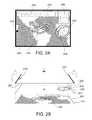
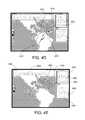
- FIG. 1Aillustrates an exemplary multi-touch display device 100 that is configured to operate in an annotation mode.
- the multi-touch display device 100is displaying informational window objects 104 , 106 , and 108 and a map object 102 .
- the multi-touch display device 100has assigned the informational window objects 104 , 106 , and 108 to a virtual layer (not shown) that is closer to the foreground of the display than the virtual layer (not shown) to which the multi-touch display device 100 has assigned the map object 102 .
- the multi-touch display device 100displays the informational window objects 104 , 106 , and 108 such that they appear in front of, or on top of, map object 102 .
- Multi-touch display device 100also is displaying a control object 110 at a virtual layer (not shown) that is closer to the foreground than either of the virtual layers to which the informational window objects 104 , 106 , and 108 or the map object 102 are assigned.
- the control object 110 provided by the multi-touch display device 100is actuatable to toggle the mode within which the multi-touch display device 100 is operating back and forth between the annotation mode and a manipulation mode. As illustrated in FIG. 1A , the multi-touch display device 100 is operating in the annotation mode. Consequently, in response to detecting user interaction with control object 110 , the multi-touch display device 100 is configured to transition the multi-touch display device 100 to the manipulation mode.
- commentators 118 and 122are interacting with the multi-touch display device 100 simultaneously. Specifically, commentator 118 is interacting with the multi-touch display device 100 in a top right-hand region of the multi-touch display device 100 that corresponds to informational window object 106 , and commentator 122 is interacting with the multi-touch display device 100 in a central region of the multi-touch display device 100 that corresponds to map object 102 .
- the multi-touch display device 100has detected input from commentator 118 as a result of commentator 118 engaging the surface of the multi-touch display device 100 with a finger.
- input from commentator 118is converted into an annotation, which the multi-touch display device 100 displays as annotation 130 .
- the detected position of the input received from commentator 118is related to the position of one or more objects and/or layers being displayed, such that the input received from commentator 118 is associated with one or more objects and/or layers presently displayed, informational window object 106 in the illustrated case.
- the multi-touch display device 100associates annotation 130 with the virtual layer to which informational window object 106 is assigned.
- the multi-touch display device 100concurrently applies the same transformation to annotation 130 as well, without requiring any additional input from commentator 118 or otherwise.
- the multi-touch display device 100also and concurrently detects input from commentator 122 as a result of commentator 122 engaging the surface of the multi-touch display device 100 .
- input from commentator 122is converted into an annotation, which the multi-touch display device 100 displays as annotation 132 .
- the detected position of the input received from commentator 122is itself related to the position of one or more objects or layers being displayed, such that the input received from commentator 122 is associated with one or more objects/layers presently displayed, map object 102 in the illustrated case.
- the multi-touch display device 100associates annotation 132 with the virtual layer to which map object 102 is assigned.
- the multi-touch display device 100concurrently applies the same transformation to annotation 132 as well, without requiring any additional input from commentator 122 or otherwise.
- the multi-touch display device 100is configured to transition between operating in the annotation mode and the manipulation mode in response to detecting that the user engaged the portion of the surface of the multi-touch display device 100 corresponding to control object 110 . Additionally or alternatively, the multi-touch display device 100 also may be configured to transition between operating in annotation mode and transformation mode in response to detecting that a user has applied a single tap (e.g., engaged the surface of the multi-touch display device 100 for less than a threshold distance and/or for less than a threshold period of time), a specific sequence of taps, a chorded tap, or any of various different system-defined gestures for transitioning operation modes to any location on the surface of the multi-touch display device 100 .
- a single tape.g., engaged the surface of the multi-touch display device 100 for less than a threshold distance and/or for less than a threshold period of time
- a specific sequence of tapse.g., engaged the surface of the multi-touch display device 100 for less than a threshold distance and/or for
- FIG. 1Billustrates the multi-touch display device 100 operating in manipulation mode.
- Commentator 122is interacting with the multi-touch display device 100 in a region of the multi-touch display device 100 that corresponds to map object 102 .
- the multi-touch display device 100detects input from commentator 122 as a result of commentator 122 engaging the surface of the multi-touch display device 100 with one finger from his left hand and one finger from his right hand. Based on the detected positions of the commentator's 122 two fingers, the multi-touch display device 100 determines to apply the input received from commentator 122 to map object 102 . Therefore, the multi-touch display device 100 interprets the input received from commentator 122 as a request to apply a transformation to the virtual layer to which map object 102 is assigned.
- the multi-touch display device 100detects that the commentator 122 is extending the distance between the two fingers with which commentator 122 is engaging the surface of the multi-touch display device 100 .
- the multi-touch display device 100uniformly increases the scale of (i.e. zooms in on) the layer to which map object 102 is assigned as well as its corresponding objects and annotations, including map object 102 and annotation 132 .
- the multi-touch display device 100maintains the visual relationships between the map object 102 and annotation 132 .
- the multi-touch display device 100applies the uniform scaling transformation operation on map object 102 and annotation 132 , but the multi-touch display device 100 does not similarly apply the uniform scaling transformation to any of the other virtual layers or their corresponding objects and annotations.
- informational window objects 104 , 106 , and 108 , annotation 130 , and control object 110remain unchanged from FIG. 1A despite the transformation operation applied to map object 102 and annotation 132 .
- informational window objects 104 , 106 , and 108 , annotation 130 , and control object 110correspond to different virtual layers than the virtual layer to which the transformation operation is applied.
- the multi-touch display device 100maintains the visuo-spatial depth of the displayed objects and annotations. For example, as the multi-touch display device 100 increases the scale of annotation 132 , annotation 132 extends into a region of the display that overlaps with the location of informational window object 108 .
- the multi-touch display device 100assigned informational window object 108 to a virtual layer (not shown) that is closer to the foreground than the virtual layer (not shown) with which the multi-touch display device 100 associated annotation 132 , the multi-touch display device displays informational window object 108 and annotation 132 such that the portion of informational window object 108 that overlaps with annotation 132 occludes the portion of annotation 132 with which it overlaps.
- multi-touch display devicesgenerally are described as universally operating in either the annotation mode or the manipulation mode.
- a multi-touch display devicemay be configured to support apportioning of the multi-touch display device into different virtual areas, each of which can be operated in a different mode.
- the surface of the multi-touch display device 100may be divided into virtual areas such that the multi-touch display device 100 interprets the detected input from user 118 as a received annotation while simultaneously interpreting the detected input from user 122 as an instruction to apply a transformation.
- a multi-touch display devicemay compose a rendered display out of multiple different virtual layers that are stacked on top of one another, thereby providing an element of depth to the display.
- a multi-touch display devicemay compose a rendered display out of any number of different virtual layers
- a multi-touch display devicecomposes a display out of a background layer, a mid-ground layer, and a foreground layer.
- the multi-touch display deviceassigns each individual object to be displayed to one of the three virtual layers.
- the multi-touch display devicethen renders the display by displaying objects assigned to the foreground layer such that they occlude, fully or partially, objects with which they overlap that are assigned to the mid-ground or background layers.
- the multi-touch display devicedisplays objects assigned to the mid-ground layer such that they occlude, fully or partially, objects with which they overlap that are assigned to the background layer.
- the multi-touch display devicealso or alternatively may support a logical ordering of the different constituent objects assigned to a single particular layer. In such cases, the multi-touch display device displays objects assigned to the same layer such that higher-ordered objects occlude lower-ordered objects assigned with which they overlap.
- the multi-touch display deviceWhen a multi-touch display device associates annotations with different layers, such as, for example, described above in connection with FIGS. 1A-1B , the multi-touch display device displays the annotations in a fashion that is consistent with the visuo-spatial depth of the layers to which the annotations are associated. In addition, for layers with which annotations have been associated, the multi-touch display device orders the annotations associated with the layer such that the annotations occupy higher levels within the layer than the objects assigned to the layer. As a result, when the multi-touch display device renders the display, annotations associated with a layer are visually overlaid on top of the objects assigned to the layer. Furthermore, the multi-touch display device also may apply a temporal ordering to the annotations associated with each layer such that recently received annotations associated with a layer occupy higher orders within the layer than older annotations associated with the layer.
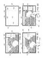
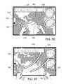
- FIGS. 2A-2Billustrate an exemplary multi-touch display device showing multiple constituent virtual layers and annotations associated with different of these multiple layers.
- FIG. 2Aillustrates multi-touch display device 200 as a user would perceive it.
- the multi-touch display device 200is displaying a map object 202 ; three informational window objects 204 , 206 , and 208 ; a control object 210 ; and two annotations B 30 and B 32 .
- the multi-touch display device 200may employ different techniques for assigning objects to and associating annotations with different layers. For present explanatory purposes, however, the assignments and associations are simply given and are illustrated in FIG. 2B .
- FIG. 2Bis an exploded view of FIG. 2A that illustrates the different constituent virtual layers within the display, the objects assigned to each layer, and the annotations associated with each layer or constituent objects therein.
- the multi-touch display device 200assigns the map object 202 to a lowest or background layer 212 , and it also associates the annotation B 30 with a lowest or background layer 212 .
- the multi-touch display device 200orders annotation B 30 , such that annotation B 30 occupies a higher order within layer 212 and thus overlays the map object 202 when the multi-touch display device 200 renders the display.
- the multi-touch display device 200assigns the informational window objects 204 , 206 , and 208 to a middle or mid-ground layer 214 , and it also associates the annotation B 32 with the middle or mid-ground layer 214 .
- the multi-touch display device 200orders annotation B 32 , such that annotation B 32 occupies a higher order within layer 214 and thus overlays informational window 208 when the multi-touch display device 200 renders the display.
- the multi-touch device 200assigns the control object 210 to a top or foreground layer 216 .
- FIGS. 3A-3Jare a series of figures of a user interacting with a multi-touch display device 300 that is configured to be operated in either of a manipulation mode or an annotation mode.
- the multi-touch display device 300is displaying a map object 302 at a first layer, three informational window objects 304 , 306 and 308 at a second layer, and a control object 310 at a third layer.
- FIG. 3Bschematically illustrates the different layers to which the multi-touch display device 300 has assigned each of the displayed objects.
- map object 302is assigned to layer 312
- the three information window objects ( 304 , 306 , 308 )are all assigned to layer 314
- the control object 300is assigned to layer 316 . Relative to layers 314 and 316 , layer 312 is further from the foreground.
- the multi-touch display device 300displays the information window objects ( 304 , 306 , and 308 ), which are assigned to layer 314 , and the control object 310 , which is assigned to layer 316 , such that the information window objects ( 304 , 306 , and 308 ) and the control object occlude the portions of the map object 302 with which they overlap.
- the multi-touch display device 300interprets detected input in different ways depending on the mode in which the multi-touch display device 300 is operating. When operating in the manipulation mode, the multi-touch display device 300 performs transformations on displayed objects in response to detecting user input. In contrast, when operating in the annotation mode, the multi-touch display device 300 interprets detected input as annotations to be applied to displayed objects or layers.
- the multi-touch display device 300provides control object 310 . Irrespective of the mode within which the multi-touch display device 300 is operating, the multi-touch display device 300 displays control object 310 at a layer that is higher than any other objects displayed by the multi-touch display device 300 .
- the visible boundary of control object 310also may define a region of the multi-touch display device 300 that is active only for receiving input to change between the transformation and annotation modes. That is to say, the visible boundary of control object 310 may define a region that is inactive for receiving input to transform or annotate an object and/or a layer.
- control object 310remains generally accessible to a user of the multi-touch display device 300 , irrespective of the mode within which the multi-touch display device is operating and other objects displayed by the multi-touch display device 300 .
- the multi-touch display device 300is configured to change the mode within which it is operating in response to detecting input in the region defined by the control object 310 .
- additional or alternative controlsmay define regions that are active only for receiving input related to such controls such that these controls, like control object 310 are immune from annotation and/or transformation.
- the multi-touch display device 300When in manipulation mode, the multi-touch display device 300 is configured to apply transformations to objects displayed on the multi-touch display device 300 in response to detecting inputs on the surface of the multi-touch display device 300 .
- the multi-touch display device 300may be configured to transform by translating, rotating, and/or uniformly scaling displayed objects in response to detecting inputs on the surface of the multi-touch display device 300 .
- the multi-touch display device 300applies such transformations on a per layer basis. As such, because the map object 302 and the information windows objects 304 , 306 , and 308 are displayed at different layers, the multi-touch display device 300 may apply a transformation to map object 302 without affecting the display of informational window objects 304 , 306 and 308 . Similarly, the multi-touch display device 300 may apply a transformation to informational window objects 304 , 306 , and 308 without affecting the display of map object 302 .
- FIGS. 3C-3Dillustrate the multi-touch display device 300 applying a transformation to an object assigned to one layer independently of objects assigned to different layers and the effect this transformation has on the other objects assigned to different layers.
- a user 318engages the multi-touch display device 300 by touching a finger 320 to its surface.
- the multi-touch display devicedetects the position at which the finger is touching its surface and determines, based on the detected position of the finger, with which layer to associate this input. In this example, the multi-touch display device 300 determines with which layer to associate the input by identifying the object that is displayed at the highest layer (i.e., closest to the foreground) at the position where the finger 320 first engaged the surface of the multi-touch display device 300 .
- the multi-touch display device 300then associates the input with the layer to which this object is assigned.
- the finger 320has engaged the surface of the multi-touch display device 300 at a position that corresponds to the map object 302 , because this is the object at the highest layer at the position on the multi-touch display device 300 engaged by the finger 320 .
- the multi-touch display device 300determines that the input is to be applied to layer 312 in response to detecting that the finger 320 engages the surface of the multi-touch display device 300 at the position corresponding to the map object 302 .
- the userhas dragged the finger 320 across the surface.
- the multi-touch display device 300detected the movement of the finger 320 and, in response, translated the map object 302 to a new position. Since the map object 302 is the only object assigned to layer 312 , the multi-touch display device translated the map object but did not manipulate any of the other objects (i.e. information window objects 304 , 306 and 308 , and control object 310 ) that are assigned to different layers.
- the usercan change the mode within which the multi-touch display device 300 is operating by engaging the portion of the surface of the multi-touch display device 300 in which control object 310 is displayed.
- the multi-touch display device 300detects the input and associates the position of the detected input with control object 310 . Since it has previously assigned control object 310 with layer 316 , the multi-touch display device 300 interprets this input as a control setting operation. As such, based on the position of the detected input, the multi-touch display device 300 will, for instance, set itself to a different mode. Therefore, in response to detecting that user 318 has engaged the surface of the multi-touch display device 300 in the location at which control object 310 is displayed, the multi-touch display device 300 transitions from manipulation mode to annotation mode.
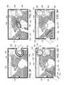
- FIGS. 3E-3Hillustrate operation of the multi-touch display device 300 in annotation mode.
- user 318engages the multi-touch display device 300 by touching a finger 320 to its surface.
- the multi-touch display device 300detects the position at which the finger 320 initially touches its surface and determines, based on the detected position of the finger, with which layer to associate this input. To establish this association, the multi-touch display device 300 determines how the initially detected position of the finger 320 relates to the visual positions of the objects being displayed by multi-touch display device 300 . In the case of FIG.
- the finger 320initially touches a position within the visual boundaries of informational window object 308 , which is assigned to layer 314 , and map object 302 , which is assigned to layer 312 . Due to the fact that layer 314 is higher (i.e., closer to the foreground) than layer 312 , the multi-touch display device 300 associates the detected input with layer 314 . Thereafter, based on the fact that the multi-touch display device 300 is operating in the annotation mode and due to having associated the input with layer 314 , the multi-touch display device 300 tracks the movement of the finger 320 and converts detected movement by the finger 320 into an annotation which the multi-touch display device 300 stores and displays as being associated with layer 314 .
- the multi-touch display device 300tracks the movement of the finger 320 and displays and stores this detected input as an annotation 330 that is associated with layer 314 .
- the multi-touch display device 300maintains this association between annotation 330 and layer 314 even though parts of the annotation 330 extend beyond the visual boundaries of informational window 308 , and thus, also extends into a region of the display that is not associated with layer 314 , but rather is associated with the map object 302 and layer 312 .
- the multi-touch display device 300treats the detected movement of the finger 320 as a single, continuous input irrespective of the fact that the movement of the finger 320 traveled beyond the visible boundaries of informational window 308 .
- the multi-touch display device 300displays the stored annotation 330 in a visuo-spatial manner that is consistent with the annotations association with layer 314 .
- the annotation 330visually occludes all objects assigned to and annotations previously associated with layer 314 and any layers visually lower (i.e. closer to the background) than layer 314 .
- annotation 330is illustrated in FIG. 3E as visually occluding informational window object 308 , which is assigned to layer 314 , and map object 302 , which is assigned to layer 312 , which is visually lower than layer 314 .
- FIG. 3Fshows user 318 moving finger 320 in a circular manner across a different part of the surface of the multi-touch display device 300 .
- the multi-touch display device 300detects that the initial position of the detected input is only within the visual boundaries of map object 302 . Therefore, because map object 302 is assigned to layer 312 , the multi-touch display device 300 associates the new detected input with layer 312 .
- the multi-touch display device 300tracks the movement of the finger 320 and converts detected movement of the finger 320 into an annotation 332 , which the multi-touch display device 300 displays and stores in a visuo-spatial manner that is consistent with layer 312 .
- Multi-touch display device 300is configured to detect multiple inputs at the same time. As illustrated in FIG. 3G , user 318 is moving finger 320 across the surface of the multi-touch display device 300 at the same time that user 322 is moving finger 324 across the surface of the multi-touch display device 300 . In response, the multi-touch display device 300 detects the circular input of finger 320 and associates the input with layer 314 by virtue of the finger 320 having initially engaged the surface of the multi-touch display device 300 in a position that is within the visual boundaries of informational window object 306 , which is assigned to layer 314 .
- the multi-touch display deviceconverts the detected circular input into an annotation 334 , which the multi-touch display device 300 displays and stores in a visuo-spatial manner that is consistent with the annotation's association with layer 314 .
- the multi-touch display device 300detects the linear input of finger 324 and associates the input with layer 312 by virtue of the finger 324 having initially engaged the surface of the multi-touch display device 300 in a position that is within the visual boundaries of map object 302 , which is assigned to layer 312 .
- the multi-touch display deviceconverts the detected linear input into an annotation 336 , which the multi-touch display device 300 displays and stores in a visuo-spatial manner that is consistent with the annotation's association with layer 314 .
- the multi-touch display device 300detects inputs and converts the detected inputs into annotations, the multi-touch display device 300 stores and displays the annotations as a function of the temporal order in which they were received. Specifically, the multi-touch display device 300 stores and displays the various different annotations associated with any given layer such that the annotations are visually stacked on top of one another in the order that they are received.
- the multi-touch display device 300detected that the initial position of the detected input fell only within the visual boundaries of map object 302 and no other object. Therefore, because map object 302 is assigned to layer 312 , the multi-touch display device 318 associated the detected input with layer 312 .
- the multi-touch display device 300converts the tracked movement of the finger 320 into an annotation 330 , which it stores and displays as being associated with layer 312 . As illustrated in FIG. 3H , as finger 320 traced this new line, finger 320 intersected previously stored and displayed annotation 336 . Consequently, because the multi-touch display device 300 is configured to store and display annotations associated with any given layer in a manner that reflects the temporal order in which they were received, the multi-touch display device 300 displays annotation 338 such that the portion of annotation 338 that overlaps with a portion of annotation 336 occludes the portion of annotation 336 that it overlaps.
- the multi-touch display devicemay not store and display annotations associated with a given layer in a manner that reflects the temporal order in which the annotations were received. Rather, for all annotations associated with a given layer, the multi-touch display device 300 may visually flatten the annotations such that they are combined into a single annotation.
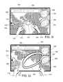
- FIGS. 3I-3Jillustrate the multi-touch display device 300 applying a transformation to layer 318 , along with its assigned objects and associated annotations, independently of other layers.
- the multi-touch display devicehas again detected that the user has engaged the surface of the multi-touch display device 300 in a position corresponding to the control object 310 , and, in response, the multi-touch display device has set itself to manipulation mode. Consequently, rather than converting received input into annotations, the multi-touch display device 300 again applies transformations to displayed layers and their assigned objects in response to detecting user interaction with the surface of the multi-touch display device 300 .
- the user 318is engaging the multi-touch display device 300 by touching two fingers 320 and 326 to its surface at the same time.
- the multi-touch display device 300detects the initial positions at which each of the two fingers 320 and 326 initially engaged its surface and determines, based on the detected initial positions of the fingers 320 and 326 , with which layer (or layers) to associate these inputs.
- the multi-touch display device 300detects that the positions at which fingers 320 and 326 initially engaged the surface of the multi-touch display device 300 correspond to positions that are located within the visual boundaries of the map object 302 , but no other objects.
- the multi-touch display device 300since map object 302 is assigned to layer 312 , the multi-touch display device 300 associated both detected inputs with layer 312 . Furthermore, since the multi-touch display device 300 associates both detected inputs with layer 312 , and because both fingers remain engaged with the multi-touch display device 300 concurrently, the multi-touch display device 300 processes and treats both detected inputs as a single input operation while both fingers remain concurrently engaged with the surface of the multi-touch display device 300 .
- the user 318is dragging finger 320 toward the lower left of the multi-touch display device 300 while simultaneously dragging finger 326 toward the lower right corner of the multi-touch display device 300 .
- the multi-touch display device 300detects the movement of the fingers 320 and 326 , and, in response, interprets the movement of the fingers as an instruction to apply a uniform scaling transform operation to layer 312 .
- the multi-touch display device 300uniformly increases the scale of (i.e., zooms in on) each object assigned to and each annotation associated with layer 312 (i.e., map object 302 and annotations 332 , 336 , and 338 ).
- the multi-touch display deviceapplies the transformation to the layer 312 as a whole, the positions of and the relationships between the objects assigned to and the annotations associated with layer 312 are preserved while the multi-touch display device 300 applies the transformation to layer 312 .
- the multi-touch display device 300zoomed in on the map object 302 , while also enlarging the annotations 332 , 336 , and 338 .
- the multi-touch display device 300maintained the spatial relationships between each of annotations 332 , 336 , and 338 and map object 302 . As such, annotations 336 and 338 are no longer visible due to the magnitude of the scale increase applied to layer 312 .
- annotation 332extends into a region of the display that overlaps with the location of informational window objects 306 and 308 , and annotation 330 .
- the multi-touch display device 300assign informational window objects 306 and 308 and annotation 330 to layer 314 , which is closer to the foreground than layer 312 , the layer to which the multi-touch display device 300 associated annotation 332 , the multi-touch display device 300 displays informational window objects 306 and 308 and annotations 330 and 332 such that the portions of informational window objects 306 and 308 and annotation 330 that overlap with annotation 332 occlude the portion of annotation 332 with which they overlap.
- a multi-touch display device that provides for multi-layer annotationmay employ various different rules to determine to which layer a received annotation is to be associated when operating in annotation mode. For example, as described above in connection with FIGS. 3C and 3E , in one implementation, a multi-touch display device identifies within which of the different objects, the visible boundaries of which the annotation was begun, is assigned to the highest layer (i.e., the layer closest to the foreground) and associates the annotation with the layer to which this object is assigned. In an alternative implementation, a multi-touch display device may extend the active region of a displayed object beyond the actual visual boundary of the object. In such an implementation, the multi-touch display device may associate a received annotation with a particular layer based on detecting that an annotation began within the extended active region of an object assigned to the particular layer.
- FIGS. 4A-4Dare a series of figures of a multi-touch display device that employs active regions that extend beyond the visual boundaries of displayed objects to determine to which layer a received annotation is to be assigned. These active regions effectively extend the boundaries of each object within which the initial position of an input may be detected so as to be associated with the object, and thus associated with the layer to which the object is assigned. Furthermore, in some implementations, in response to associating an annotation to a layer to which an initially engaged object corresponds, the multi-touch display device temporarily may extend the active region for the initially engaged object to temporarily include a region surrounding the newly stored and displayed annotation.
- the active region for the objecttemporarily may be extended to include a region surrounding the portion of the annotation stroke that extends beyond the active region of the object.
- any annotation stroke received within the extended active regionwill be treated as a continuation of the original annotation stroke, and thus will be associated with the same layer as the original annotation stroke.
- This functionalitymay prove useful in preserving the continuity of annotations that extend beyond the active regions of an object and that require a user to temporarily disengage the surface because the annotation requires multiple strokes (e.g., dotting an “i”, crossing a “t”, or drawing an arrowhead).
- FIG. 4Aillustrates the multi-touch display device 400 , operating in annotation mode, maintaining active regions around a subset of the objects being displayed.
- dotted linesare used to represent active regions 440 , 442 , and 444 which correspond to informational window objects 404 , 406 , and 408 , respectively, and which extend beyond the visual boundaries of the objects to which they correspond.
- the multi-touch display device 400may not actually display the dotted lines.
- finger 420has engaged the surface of the multi-touch display device 400 within active region 440 .
- the multi-touch display device 400detects the position of the input and its location within active region 440 , and determines that the input is to be applied to layer 414 , because the active region 440 is maintained around information window 404 , which is assigned to layer 414 .
- multi-touch display device 400detects the movement of the finger, converts the input into an annotation 450 , and stores and displays the annotation 450 in a manner that is visuo-spatially consistent with layer 414 .
- the multi-touch display device 400temporarily extends active region 440 to encompass an area around the annotation 450 for a specified period of time.
- the multi-touch display device 400allows a user to reposition the user's finger (or other input device) relative to the surface of the multi-touch display device 400 and later reengage the surface to continue providing input related to the annotation without losing the context of the annotation.
- finger 420engages the surface of the multi-touch display device 400 surrounding the initial annotation stroke within extended active region 440 during the temporary time period during which the multi-touch display device 400 maintains the extended active region 440 .
- Multi-touch display device 400detects the position of the input and its location within extended active region 440 , and determines that the input is to be associated with layer 414 , because the extended active region 440 corresponds to informational window object 404 , which is assigned to layer 414 . Therefore, referring to FIG.
- multi-touch display device 400detects the movement of the finger 420 , converts the input into an annotation 452 , and stores and displays annotation 452 in a manner that is visuo-spatially consistent with layer 414 . Thereafter, as illustrated in FIG. 4D , the multi-touch display device 400 again extends active region 440 , this time to temporarily encompass an area surrounding annotation 450 . As shown in FIG. 4E , however, after the specified period of time has elapsed, the multi-touch display 400 deactivates the extended active region 440 surrounding annotations 450 and 452 , and the active region 440 reverts to its original size.
- the multi-touch display 400would have associated these annotations differently. Specifically, the multi-touch display device 400 would have associated annotation 450 with layer 414 , because the position of the detected input responsible for annotation 450 would have fallen within the visual boundaries of object 404 , which is associated with layer 414 . However, the multi-touch display device 400 would have associated annotation 452 with layer 412 , because the position of the detected input responsible for annotation 452 would have only fallen within the visual boundaries of object 402 , which is associated with layer 412 . However, such associations may have prevented a user from inputting an arrow-shaped annotation as intended.
- Another example of a rule that may be employed to determine to which layer to associate a received annotationis to determine which displayed object the received annotation occupies the largest portion of and to associate the received annotation with the layer to which this object is assigned.
- multi-touch display device 400can establish active regions utilizing a number of different techniques.
- the multi-touch display device 400stores the active region(s) of each layer to represent an expansion of the visual boundaries of one, some or all of the objects assigned to that layer.
- These active regionsmay be established through a manual input process, in which the active region boundary is itself stored in addition to the visual boundary of the displayed object.
- the active region boundarymay be established by performing a mathematical operation on the boundary of a displayed object. For instance, an absolute scalar may be applied (e.g., added) to create an active boundary region that corresponds to a uniform expansion of the boundary otherwise associated with a displayed object. Implementations of these manual processes result in active regions such as those shown in FIG. 4A , which have a border that differs from the displayed border of a corresponding displayed object.
- Another manual input processinvolves establishing an active region boundary based on manual input from the user. For example, the active region associated with a displayed object that is being annotated may be expanded based on the annotation by including the annotation region as part of the object's active display region. Similarly, a user may indicate where the user wants the active region(s) to be created for each layer by drawing the active region(s) on the surface of the multi-touch display device 400 . The multi-touch display device 400 stores this input as active region(s) for the indicated layer.
- multi-touch display device 400stores the active region(s) of each layer as an expansion of the visual boundaries of one, some or all of the objects assigned to and annotations associated with that layer. Implementation of this second technique results in active regions similar to those shown in FIG. 4D , where boundaries may extend beyond the displayed object boundaries in non-uniform ways, according to the annotations applied to those objects, for instance.
- the multi-touch display device 400stores the active region(s) of each layer as a rectangle or other geometric shape encompassing each object(s) assigned to the layer.
- the active regions established in each of these techniquesmay be grown or expanded dynamically based on, for example, how frequently the active region is contacted, or the input of annotations, as discussed above in relation to FIGS. 4A-4E .
- the multi-touch display device 400interprets all detected inputs as encompassing an area around the position at which the input is detected. As such, the multi-touch display device 400 relates the detected input with the object associated with the highest (i.e. closest to the foreground) layer within a given radius of the position at which the input was detected, and associates the input with this highest layer.
- One example of a process that may be employed by a multi-touch display device to create an annotationinvolves detecting movement of a user's finger (or some other input mechanism) about the surface of the multi-touch display device. In response to detecting the tracked movement of the finger, the multi-touch display device converts the tracked movement of the user's finger into an image. In some implementations, as a user has traced a path across the surface of the multi-touch display device, the multi-touch display device frequently (e.g., 30 or 60 times per second) updates the converted image to reflect the additional movement of the user's finger such that the user perceives the annotation as following the path traced by the user's finger substantially in real time.
- the multi-touch display devicefrequently (e.g., 30 or 60 times per second) updates the converted image to reflect the additional movement of the user's finger such that the user perceives the annotation as following the path traced by the user's finger substantially in real time.
- the multi-touch display deviceassociates the image representing the annotation with a particular layer of the multi-touch display device (e.g., by assigning a layer ID to the image) and perhaps also a particular position within the associated layer (e.g., by assigning the image x- and y-coordinates). Furthermore, in some implementations, the multi-touch display device also may assign the image representing the annotation an order within the layer to which the image is associated (e.g., by assigning the image an order layer), thereby providing a sense of depth even within the layer.
- a multi-touch display devicemaintains, for example, within a memory storage component, one or more data structures for recording relationships between objects and annotations to be displayed by the multi-touch display device. As objects and annotations are added to the display, the multi-touch display device updates the data structure(s) appropriately.
- the multi-touch display device 300 or associated hardwaremay maintain a data structure that records relationships between each of the objects and annotations displayed by the multi-touch display device 300 .
- a data structurerecords a layer ID, an order ID, and location information for each object and annotation.
- the multi-touch display device 300adds the annotations and their Layer IDs, Order IDs, and position information to the stored data structure for subsequent access. Table 1 below provides a representative example of such a data structure.
- the data structurerecords the layer ID, the order ID, as well as position information for each object and each annotation displayed by the multi-touch display device 300 .
- the layer ID recorded for each object or annotationreflects the layer to which the corresponding object or annotation corresponds.
- the order ID for each object or annotationreflects the order of the object or annotation within the layer to which it corresponds.
- the multi-touch display device 300may assign order IDs to annotations associated with a given layer as a function of the temporal order in which the annotations associated with the given layer were received, with recently received annotations being assigned higher order IDs than earlier received annotations.
- the multi-touch display deviceis able to provide a sense of depth to the annotations associated with any given layer that is consistent with the temporal order within which the annotations associated with that given layer were received.
- the data structure reflected in Table 1also records position information for each displayed object or annotation that reveals information about the location of the object or annotation within the layer to which it corresponds.
- the multi-touch display device 300When operating in manipulation mode, in response to detecting receipt of user input, the multi-touch display device 300 associates received input with a particular one of layers 312 , 314 , and 316 and, thereafter, as a function of the received input, performs a transformation operation to the particular layer including any objects or annotations corresponding to the particular layer. In order to accomplish this, the multi-touch display device 300 accesses the data structure, searches for and identifies objects and annotations corresponding to the particular layer, and, thereafter, performs the appropriate transformation operation to each so-identified object or annotation. For example, referring to FIG. 3J , as discussed above, the multi-touch display device 300 associates the input imparted by the movement of fingers 320 and 326 to 312 .
- the multi-touch display device 300accesses the data structure and searches for all objects and annotations corresponding to layer 312 . In this case, the multi-touch display device 300 determines, based on the data structure, that map object 302 and annotations 332 , 336 , and 338 all correspond to layer 312 . Consequently, the multi-touch display device 300 applies the transformation to each of map object 312 and annotations 332 , 336 , and 338 .
- a multi-touch display device operating in the annotation modeis configured to concurrently receive multiple annotations to be associated with the same layer.
- the multi-touch display device 500detects the movement of finger 502 on the surface of the multi-touch display device 500 and converts the detected movement into annotation 504 , which the multi-touch display device associates with the virtual layer (not shown) to which informational window object 506 is assigned based on the location of the detected movement of finger 502 on the surface of the multi-touch display device 500 .
- the multi-touch display device 500detects the movement of fingers 520 and 522 and converts the detected movement of fingers 520 and 522 into annotations 524 and 526 , respectively. (Although fingers 520 and 522 are illustrated as concurrently engaging the surface of the multi-touch display device 500 in FIG. 5B , fingers 520 and 522 may or may not have initially engaged the surface of the multi-touch display device 500 at the same time.) In addition, based on the location of the detected movements of fingers 520 and 522 , the multi-touch display device 500 associates both annotation 524 and annotation 526 with the virtual level (not shown) to which map object 528 is assigned.
- the multi-touch display device 500detects subsequent movements of finger 522 and converts these subsequent movements into annotations 530 and 532 , which the multi-touch display device 500 associates with the virtual layer (not shown) to which map object 528 is assigned based on the locations of the detected subsequent movements of finger 522 .
- the multi-touch display device 500is illustrated as operating in the manipulation mode.
- fingers 502 and 522are engaging the surface of the multi-touch display device 500 concurrently.
- fingers 502 and 522did not necessarily initially engage the surface of the multi-touch display device 500 at the same time.
- the multi-touch display device 500detects the movements of fingers 502 and 522 while engaged with the surface of the multi-touch display device 500 .
- the multi-touch display device 500associates the received input with the virtual layer (not shown) to which map object 528 is assigned.
- the multi-touch display device 500applies a corresponding transformation to the virtual layer to which the map object 528 is assigned.
- the annotations 524 , 526 , 530 , and 532 and map object 528are transformed as a result, while the other displayed annotations and objects remain unchanged.
- the described systems, methods, and techniquesmay be implemented in digital electronic circuitry, computer hardware, firmware, software, or in combinations of these elements. Apparatuses embodying these techniques may include appropriate input and output devices, a computer processor, and a tangible computer-readable storage medium on which a computer program or other computer-readable instructions are stored for execution by one or more processing devices (e.g., a programmable processor).
- processing devicese.g., a programmable processor
- a process embodying these techniquesmay be performed by a programmable processor executing a program of instructions to perform desired functions by operating on input data and generating appropriate output.
- the techniquesmay be implemented in one or more computer programs that are executable on a programmable system including at least one programmable processor coupled to receive data and instructions from, and to transmit data and instructions to, a data storage system, at least one input device, and at least one output device.
- Each computer programmay be implemented in a high-level procedural or object-oriented programming language, or in assembly or machine language if desired; and in any case, the language may be a compiled or interpreted language.
- Suitable processorsinclude, by way of example, both general and special purpose microprocessors. Generally, a processor will receive instructions and data from a read-only memory and/or a random access memory.
- Storage devices suitable for storing computer program instructions and datainclude all forms of non-volatile memory, including by way of example semiconductor memory devices, such as Erasable Programmable Read-Only Memory (EPROM), Electrically Erasable Programmable Read-Only Memory (EEPROM), and flash memory devices; magnetic disks such as internal hard disks and removable disks; magneto-optical disks; and Compact Disc Read-Only Memory (CD-ROM). Any of the foregoing may be supplemented by, or incorporated in, specially-designed application-specific integrated circuits (ASICs).
- ASICsapplication-specific integrated circuits
- Multi-touch display devicesencompass a wide variety of display devices and associated systems and components. Some multi-touch display devices require physical contact with a surface of the multi-touch display device in order to receive input. For example, such a multi-touch display device may receive input by detecting contact with a surface of the multi-touch display device by a finger, a stylus, some other mechanical, electro-mechanical, or magnetic input mechanism and/or any combination of multiple such input mechanisms at the same time. Furthermore, some such multi-touch display devices may be configured such that the surface that receives input may appear to be the same surface on which the multi-touch display device displays objects (whether or not the surface that receives input actually is the same surface as the surface on which the multi-touch display device displays objects).
- multi-touch display devicesmay receive input on a surface that is clearly remote and distinct from the surface on which the multi-touch display device displays objects.
- a multi-touch display systemis a multi-point input capable standalone tablet that provides input to a remote and distinct display.
- multi-touch display devicesdo not require physical contact with the surface of the multi-touch display device in order to receive input.
- such multi-touch display devicesmay receive input by detecting the presence of a finger, a stylus, some other mechanical, electro-mechanical, or magnetic input mechanism and/or any combination of multiple such input mechanisms in the vicinity of the surface of the multi-touch display device even when such input mechanisms are not in physical contact with the surface of the multi-touch display device.
- the various different transformations and annotations disclosed hereinmay be implemented by any other type of multi-point computing system configured to receive multiple inputs at the same, including, for example, systems configured to receive concurrent input from multiple pointing devices (e.g., multiple computer mice) and/or concurrent input from one or more pointing devices and another input device (e.g., a keyboard).
- systemsconfigured to receive concurrent input from multiple pointing devices (e.g., multiple computer mice) and/or concurrent input from one or more pointing devices and another input device (e.g., a keyboard).
- some of the various different transformations and annotations disclosed hereinare not limited to implementation on a multi-touch device and thus may be implemented on a single-point device.
Landscapes
- Engineering & Computer Science (AREA)
- Theoretical Computer Science (AREA)
- General Engineering & Computer Science (AREA)
- Physics & Mathematics (AREA)
- General Physics & Mathematics (AREA)
- Human Computer Interaction (AREA)
- Health & Medical Sciences (AREA)
- General Health & Medical Sciences (AREA)
- Audiology, Speech & Language Pathology (AREA)
- Computational Linguistics (AREA)
- Artificial Intelligence (AREA)
- Computer Vision & Pattern Recognition (AREA)
- Psychiatry (AREA)
- Social Psychology (AREA)
- Multimedia (AREA)
- User Interface Of Digital Computer (AREA)
Abstract
Description
| TABLE 1 | ||||
| Object/Annotation ID | Layer ID | Order | Position Information | |
| 302 | 312 | 0 | a, | |
| 304 | 314 | 0 | c, | |
| 306 | 314 | 0 | e, | |
| 308 | 314 | 0 | g, | |
| 310 | 316 | 0 | i, | |
| 330 | 314 | 1 | k, | |
| 332 | 314 | 2 | m, | |
| 334 | 314 | 3 | o, | |
| 336 | 312 | 1 | q, | |
| 338 | 312 | 2 | s, t | |
As reflected in Table 1, the data structure records the layer ID, the order ID, as well as position information for each object and each annotation displayed by the
Claims (31)
Priority Applications (1)
| Application Number | Priority Date | Filing Date | Title |
|---|---|---|---|
| US12/652,632US9477649B1 (en) | 2009-01-05 | 2010-01-05 | Multi-layer telestration on a multi-touch display device |
Applications Claiming Priority (2)
| Application Number | Priority Date | Filing Date | Title |
|---|---|---|---|
| US14262509P | 2009-01-05 | 2009-01-05 | |
| US12/652,632US9477649B1 (en) | 2009-01-05 | 2010-01-05 | Multi-layer telestration on a multi-touch display device |
Publications (1)
| Publication Number | Publication Date |
|---|---|
| US9477649B1true US9477649B1 (en) | 2016-10-25 |
Family
ID=57136566
Family Applications (1)
| Application Number | Title | Priority Date | Filing Date |
|---|---|---|---|
| US12/652,632Active2033-08-29US9477649B1 (en) | 2009-01-05 | 2010-01-05 | Multi-layer telestration on a multi-touch display device |
Country Status (1)
| Country | Link |
|---|---|
| US (1) | US9477649B1 (en) |
Cited By (185)
| Publication number | Priority date | Publication date | Assignee | Title |
|---|---|---|---|---|
| US20140281932A1 (en)* | 2013-03-15 | 2014-09-18 | Google Inc. | Document scale and position optimization |
| US20150268828A1 (en)* | 2014-03-18 | 2015-09-24 | Panasonic Intellectual Property Management Co., Ltd. | Information processing device and computer program |
| US20180153542A1 (en)* | 2013-08-23 | 2018-06-07 | Ethicon Llc | Torque optimization for surgical instruments |
| US20180357212A1 (en)* | 2017-06-13 | 2018-12-13 | Microsoft Technology Licensing, Llc | Detecting occlusion of digital ink |
| US20190079664A1 (en)* | 2017-09-14 | 2019-03-14 | Sap Se | Hybrid gestures for visualizations |
| US10338736B1 (en)* | 2011-08-05 | 2019-07-02 | P4tents1, LLC | Devices, methods, and graphical user interfaces for manipulating user interface objects with visual and/or haptic feedback |
| US10671450B2 (en) | 2017-05-02 | 2020-06-02 | Facebook, Inc. | Coalescing events framework |
| US10691326B2 (en) | 2013-03-15 | 2020-06-23 | Google Llc | Document scale and position optimization |
| CN111506689A (en)* | 2020-04-13 | 2020-08-07 | 腾讯科技(深圳)有限公司 | Electronic map rendering method and device based on artificial intelligence and electronic equipment |
| US10937108B1 (en) | 2020-01-17 | 2021-03-02 | Pearl Inc. | Computer vision-based claims processing |
| US20210073977A1 (en)* | 2019-09-05 | 2021-03-11 | Pearl Inc. | Systems and methods for automated medical image annotation |
| US11055343B2 (en)* | 2015-10-05 | 2021-07-06 | Pinterest, Inc. | Dynamic search control invocation and visual search |
| US11069019B2 (en) | 2017-05-04 | 2021-07-20 | Facebook, Inc. | Multi-threaded asynchronous frame processing |
| US11126653B2 (en) | 2017-09-22 | 2021-09-21 | Pinterest, Inc. | Mixed type image based search results |
| US11389131B2 (en) | 2018-06-27 | 2022-07-19 | Denti.Ai Technology Inc. | Systems and methods for processing of dental images |
| US11609946B2 (en) | 2015-10-05 | 2023-03-21 | Pinterest, Inc. | Dynamic search input selection |
| US11620331B2 (en) | 2017-09-22 | 2023-04-04 | Pinterest, Inc. | Textual and image based search |
| US20230176718A1 (en)* | 2021-11-16 | 2023-06-08 | Figma, Inc. | Commenting feature for graphic design systems |
| US11676701B2 (en) | 2019-09-05 | 2023-06-13 | Pearl Inc. | Systems and methods for automated medical image analysis |
| US11684434B2 (en) | 2019-06-28 | 2023-06-27 | Cilag Gmbh International | Surgical RFID assemblies for instrument operational setting control |
| US11684361B2 (en) | 2008-09-23 | 2023-06-27 | Cilag Gmbh International | Motor-driven surgical cutting instrument |
| US11696757B2 (en) | 2021-02-26 | 2023-07-11 | Cilag Gmbh International | Monitoring of internal systems to detect and track cartridge motion status |
| US11696761B2 (en) | 2019-03-25 | 2023-07-11 | Cilag Gmbh International | Firing drive arrangements for surgical systems |
| US11696759B2 (en) | 2017-06-28 | 2023-07-11 | Cilag Gmbh International | Surgical stapling instruments comprising shortened staple cartridge noses |
| US11701111B2 (en) | 2019-12-19 | 2023-07-18 | Cilag Gmbh International | Method for operating a surgical stapling instrument |
| US11701115B2 (en) | 2016-12-21 | 2023-07-18 | Cilag Gmbh International | Methods of stapling tissue |
| US11701113B2 (en) | 2021-02-26 | 2023-07-18 | Cilag Gmbh International | Stapling instrument comprising a separate power antenna and a data transfer antenna |
| US11707273B2 (en) | 2012-06-15 | 2023-07-25 | Cilag Gmbh International | Articulatable surgical instrument comprising a firing drive |
| US11712244B2 (en) | 2015-09-30 | 2023-08-01 | Cilag Gmbh International | Implantable layer with spacer fibers |
| US11717291B2 (en) | 2021-03-22 | 2023-08-08 | Cilag Gmbh International | Staple cartridge comprising staples configured to apply different tissue compression |
| US11717297B2 (en) | 2014-09-05 | 2023-08-08 | Cilag Gmbh International | Smart cartridge wake up operation and data retention |
| US11717294B2 (en) | 2014-04-16 | 2023-08-08 | Cilag Gmbh International | End effector arrangements comprising indicators |
| US11723658B2 (en) | 2021-03-22 | 2023-08-15 | Cilag Gmbh International | Staple cartridge comprising a firing lockout |
| US11723662B2 (en) | 2021-05-28 | 2023-08-15 | Cilag Gmbh International | Stapling instrument comprising an articulation control display |
| US11723657B2 (en) | 2021-02-26 | 2023-08-15 | Cilag Gmbh International | Adjustable communication based on available bandwidth and power capacity |
| US11730477B2 (en) | 2008-10-10 | 2023-08-22 | Cilag Gmbh International | Powered surgical system with manually retractable firing system |
| US11730471B2 (en) | 2016-02-09 | 2023-08-22 | Cilag Gmbh International | Articulatable surgical instruments with single articulation link arrangements |
| US11730474B2 (en) | 2005-08-31 | 2023-08-22 | Cilag Gmbh International | Fastener cartridge assembly comprising a movable cartridge and a staple driver arrangement |
| US11730473B2 (en) | 2021-02-26 | 2023-08-22 | Cilag Gmbh International | Monitoring of manufacturing life-cycle |
| US11737751B2 (en) | 2020-12-02 | 2023-08-29 | Cilag Gmbh International | Devices and methods of managing energy dissipated within sterile barriers of surgical instrument housings |
| US11737754B2 (en) | 2010-09-30 | 2023-08-29 | Cilag Gmbh International | Surgical stapler with floating anvil |
| US11737749B2 (en) | 2021-03-22 | 2023-08-29 | Cilag Gmbh International | Surgical stapling instrument comprising a retraction system |
| US11744581B2 (en) | 2020-12-02 | 2023-09-05 | Cilag Gmbh International | Powered surgical instruments with multi-phase tissue treatment |
| US11749877B2 (en) | 2021-02-26 | 2023-09-05 | Cilag Gmbh International | Stapling instrument comprising a signal antenna |
| US11744593B2 (en) | 2019-06-28 | 2023-09-05 | Cilag Gmbh International | Method for authenticating the compatibility of a staple cartridge with a surgical instrument |
| US11744603B2 (en) | 2021-03-24 | 2023-09-05 | Cilag Gmbh International | Multi-axis pivot joints for surgical instruments and methods for manufacturing same |
| US11744583B2 (en) | 2021-02-26 | 2023-09-05 | Cilag Gmbh International | Distal communication array to tune frequency of RF systems |
| US11744588B2 (en) | 2015-02-27 | 2023-09-05 | Cilag Gmbh International | Surgical stapling instrument including a removably attachable battery pack |
| US11751869B2 (en) | 2021-02-26 | 2023-09-12 | Cilag Gmbh International | Monitoring of multiple sensors over time to detect moving characteristics of tissue |
| US11751867B2 (en) | 2017-12-21 | 2023-09-12 | Cilag Gmbh International | Surgical instrument comprising sequenced systems |
| US11759202B2 (en) | 2021-03-22 | 2023-09-19 | Cilag Gmbh International | Staple cartridge comprising an implantable layer |
| US11759208B2 (en) | 2015-12-30 | 2023-09-19 | Cilag Gmbh International | Mechanisms for compensating for battery pack failure in powered surgical instruments |
| US11771426B2 (en) | 2007-01-10 | 2023-10-03 | Cilag Gmbh International | Surgical instrument with wireless communication |
| US11776677B2 (en) | 2021-01-06 | 2023-10-03 | Pearl Inc. | Computer vision-based analysis of provider data |
| US11771419B2 (en) | 2019-06-28 | 2023-10-03 | Cilag Gmbh International | Packaging for a replaceable component of a surgical stapling system |
| US11779420B2 (en) | 2012-06-28 | 2023-10-10 | Cilag Gmbh International | Robotic surgical attachments having manually-actuated retraction assemblies |
| US11779336B2 (en) | 2016-02-12 | 2023-10-10 | Cilag Gmbh International | Mechanisms for compensating for drivetrain failure in powered surgical instruments |
| US11779330B2 (en) | 2020-10-29 | 2023-10-10 | Cilag Gmbh International | Surgical instrument comprising a jaw alignment system |
| US11786243B2 (en) | 2021-03-24 | 2023-10-17 | Cilag Gmbh International | Firing members having flexible portions for adapting to a load during a surgical firing stroke |
| US11786239B2 (en) | 2021-03-24 | 2023-10-17 | Cilag Gmbh International | Surgical instrument articulation joint arrangements comprising multiple moving linkage features |
| US11793518B2 (en) | 2006-01-31 | 2023-10-24 | Cilag Gmbh International | Powered surgical instruments with firing system lockout arrangements |
| US11793514B2 (en) | 2021-02-26 | 2023-10-24 | Cilag Gmbh International | Staple cartridge comprising sensor array which may be embedded in cartridge body |
| US11793512B2 (en) | 2005-08-31 | 2023-10-24 | Cilag Gmbh International | Staple cartridges for forming staples having differing formed staple heights |
| US11793509B2 (en) | 2012-03-28 | 2023-10-24 | Cilag Gmbh International | Staple cartridge including an implantable layer |
| US11793513B2 (en) | 2017-06-20 | 2023-10-24 | Cilag Gmbh International | Systems and methods for controlling motor speed according to user input for a surgical instrument |
| US11793516B2 (en) | 2021-03-24 | 2023-10-24 | Cilag Gmbh International | Surgical staple cartridge comprising longitudinal support beam |
| US11801047B2 (en) | 2008-02-14 | 2023-10-31 | Cilag Gmbh International | Surgical stapling system comprising a control circuit configured to selectively monitor tissue impedance and adjust control of a motor |
| US11806011B2 (en) | 2021-03-22 | 2023-11-07 | Cilag Gmbh International | Stapling instrument comprising tissue compression systems |
| US11811253B2 (en) | 2016-04-18 | 2023-11-07 | Cilag Gmbh International | Surgical robotic system with fault state detection configurations based on motor current draw |
| US11806013B2 (en) | 2012-06-28 | 2023-11-07 | Cilag Gmbh International | Firing system arrangements for surgical instruments |
| US11812958B2 (en) | 2014-12-18 | 2023-11-14 | Cilag Gmbh International | Locking arrangements for detachable shaft assemblies with articulatable surgical end effectors |
| US11812954B2 (en) | 2008-09-23 | 2023-11-14 | Cilag Gmbh International | Robotically-controlled motorized surgical instrument with an end effector |
| US11812965B2 (en) | 2010-09-30 | 2023-11-14 | Cilag Gmbh International | Layer of material for a surgical end effector |
| US11812964B2 (en) | 2021-02-26 | 2023-11-14 | Cilag Gmbh International | Staple cartridge comprising a power management circuit |
| US11826012B2 (en) | 2021-03-22 | 2023-11-28 | Cilag Gmbh International | Stapling instrument comprising a pulsed motor-driven firing rack |
| US11826042B2 (en) | 2021-03-22 | 2023-11-28 | Cilag Gmbh International | Surgical instrument comprising a firing drive including a selectable leverage mechanism |
| US11832816B2 (en) | 2021-03-24 | 2023-12-05 | Cilag Gmbh International | Surgical stapling assembly comprising nonplanar staples and planar staples |
| US11841735B2 (en) | 2017-09-22 | 2023-12-12 | Pinterest, Inc. | Object based image search |
| US11839352B2 (en) | 2007-01-11 | 2023-12-12 | Cilag Gmbh International | Surgical stapling device with an end effector |
| US11839375B2 (en) | 2005-08-31 | 2023-12-12 | Cilag Gmbh International | Fastener cartridge assembly comprising an anvil and different staple heights |
| US11849946B2 (en) | 2015-09-23 | 2023-12-26 | Cilag Gmbh International | Surgical stapler having downstream current-based motor control |
| US11849952B2 (en) | 2010-09-30 | 2023-12-26 | Cilag Gmbh International | Staple cartridge comprising staples positioned within a compressible portion thereof |
| US11849941B2 (en) | 2007-06-29 | 2023-12-26 | Cilag Gmbh International | Staple cartridge having staple cavities extending at a transverse angle relative to a longitudinal cartridge axis |
| US11850310B2 (en) | 2010-09-30 | 2023-12-26 | Cilag Gmbh International | Staple cartridge including an adjunct |
| US11849943B2 (en) | 2020-12-02 | 2023-12-26 | Cilag Gmbh International | Surgical instrument with cartridge release mechanisms |
| US11849944B2 (en) | 2021-03-24 | 2023-12-26 | Cilag Gmbh International | Drivers for fastener cartridge assemblies having rotary drive screws |
| US11849945B2 (en) | 2021-03-24 | 2023-12-26 | Cilag Gmbh International | Rotary-driven surgical stapling assembly comprising eccentrically driven firing member |
| US11857181B2 (en) | 2007-06-04 | 2024-01-02 | Cilag Gmbh International | Robotically-controlled shaft based rotary drive systems for surgical instruments |
| US11857187B2 (en) | 2010-09-30 | 2024-01-02 | Cilag Gmbh International | Tissue thickness compensator comprising controlled release and expansion |
| US11857183B2 (en) | 2021-03-24 | 2024-01-02 | Cilag Gmbh International | Stapling assembly components having metal substrates and plastic bodies |
| US11871925B2 (en) | 2020-07-28 | 2024-01-16 | Cilag Gmbh International | Surgical instruments with dual spherical articulation joint arrangements |
| US11871939B2 (en) | 2017-06-20 | 2024-01-16 | Cilag Gmbh International | Method for closed loop control of motor velocity of a surgical stapling and cutting instrument |
| US11871923B2 (en) | 2008-09-23 | 2024-01-16 | Cilag Gmbh International | Motorized surgical instrument |
| US11877748B2 (en) | 2006-10-03 | 2024-01-23 | Cilag Gmbh International | Robotically-driven surgical instrument with E-beam driver |
| US11883020B2 (en) | 2006-01-31 | 2024-01-30 | Cilag Gmbh International | Surgical instrument having a feedback system |
| US11883025B2 (en) | 2010-09-30 | 2024-01-30 | Cilag Gmbh International | Tissue thickness compensator comprising a plurality of layers |
| USD1013170S1 (en) | 2020-10-29 | 2024-01-30 | Cilag Gmbh International | Surgical instrument assembly |
| US11883026B2 (en) | 2014-04-16 | 2024-01-30 | Cilag Gmbh International | Fastener cartridge assemblies and staple retainer cover arrangements |
| US11882987B2 (en) | 2004-07-28 | 2024-01-30 | Cilag Gmbh International | Articulating surgical stapling instrument incorporating a two-piece E-beam firing mechanism |
| US11890015B2 (en) | 2015-09-30 | 2024-02-06 | Cilag Gmbh International | Compressible adjunct with crossing spacer fibers |
| US11890010B2 (en) | 2020-12-02 | 2024-02-06 | Cllag GmbH International | Dual-sided reinforced reload for surgical instruments |
| US11890008B2 (en) | 2006-01-31 | 2024-02-06 | Cilag Gmbh International | Surgical instrument with firing lockout |
| US11890012B2 (en) | 2004-07-28 | 2024-02-06 | Cilag Gmbh International | Staple cartridge comprising cartridge body and attached support |
| US11890029B2 (en) | 2006-01-31 | 2024-02-06 | Cilag Gmbh International | Motor-driven surgical cutting and fastening instrument |
| US11890005B2 (en) | 2017-06-29 | 2024-02-06 | Cilag Gmbh International | Methods for closed loop velocity control for robotic surgical instrument |
| US11896218B2 (en) | 2021-03-24 | 2024-02-13 | Cilag Gmbh International | Method of using a powered stapling device |
| US11896219B2 (en) | 2021-03-24 | 2024-02-13 | Cilag Gmbh International | Mating features between drivers and underside of a cartridge deck |
| US11896217B2 (en) | 2020-10-29 | 2024-02-13 | Cilag Gmbh International | Surgical instrument comprising an articulation lock |
| US11896222B2 (en) | 2017-12-15 | 2024-02-13 | Cilag Gmbh International | Methods of operating surgical end effectors |
| US11903582B2 (en) | 2021-03-24 | 2024-02-20 | Cilag Gmbh International | Leveraging surfaces for cartridge installation |
| US11903581B2 (en) | 2019-04-30 | 2024-02-20 | Cilag Gmbh International | Methods for stapling tissue using a surgical instrument |
| US11911027B2 (en) | 2010-09-30 | 2024-02-27 | Cilag Gmbh International | Adhesive film laminate |
| US11918222B2 (en) | 2014-04-16 | 2024-03-05 | Cilag Gmbh International | Stapling assembly having firing member viewing windows |
| US11918212B2 (en) | 2015-03-31 | 2024-03-05 | Cilag Gmbh International | Surgical instrument with selectively disengageable drive systems |
| US11918210B2 (en) | 2014-10-16 | 2024-03-05 | Cilag Gmbh International | Staple cartridge comprising a cartridge body including a plurality of wells |
| US11918220B2 (en) | 2012-03-28 | 2024-03-05 | Cilag Gmbh International | Tissue thickness compensator comprising tissue ingrowth features |
| US11918208B2 (en) | 2011-05-27 | 2024-03-05 | Cilag Gmbh International | Robotically-controlled shaft based rotary drive systems for surgical instruments |
| US11918215B2 (en) | 2016-12-21 | 2024-03-05 | Cilag Gmbh International | Staple cartridge with array of staple pockets |
| US11931034B2 (en) | 2016-12-21 | 2024-03-19 | Cilag Gmbh International | Surgical stapling instruments with smart staple cartridges |
| US11931038B2 (en) | 2014-10-29 | 2024-03-19 | Cilag Gmbh International | Cartridge assemblies for surgical staplers |
| USD1018577S1 (en) | 2017-06-28 | 2024-03-19 | Cilag Gmbh International | Display screen or portion thereof with a graphical user interface for a surgical instrument |
| US11931028B2 (en) | 2016-04-15 | 2024-03-19 | Cilag Gmbh International | Surgical instrument with multiple program responses during a firing motion |
| US11931025B2 (en) | 2020-10-29 | 2024-03-19 | Cilag Gmbh International | Surgical instrument comprising a releasable closure drive lock |
| US11937816B2 (en) | 2021-10-28 | 2024-03-26 | Cilag Gmbh International | Electrical lead arrangements for surgical instruments |
| US11944296B2 (en) | 2020-12-02 | 2024-04-02 | Cilag Gmbh International | Powered surgical instruments with external connectors |
| US11944300B2 (en) | 2017-08-03 | 2024-04-02 | Cilag Gmbh International | Method for operating a surgical system bailout |
| US11944338B2 (en) | 2015-03-06 | 2024-04-02 | Cilag Gmbh International | Multiple level thresholds to modify operation of powered surgical instruments |
| US11950777B2 (en) | 2021-02-26 | 2024-04-09 | Cilag Gmbh International | Staple cartridge comprising an information access control system |
| US11957339B2 (en) | 2018-08-20 | 2024-04-16 | Cilag Gmbh International | Method for fabricating surgical stapler anvils |
| US11957345B2 (en) | 2013-03-01 | 2024-04-16 | Cilag Gmbh International | Articulatable surgical instruments with conductive pathways for signal communication |
| US11963680B2 (en) | 2017-10-31 | 2024-04-23 | Cilag Gmbh International | Cartridge body design with force reduction based on firing completion |
| US11974742B2 (en) | 2017-08-03 | 2024-05-07 | Cilag Gmbh International | Surgical system comprising an articulation bailout |
| US11974746B2 (en) | 2014-04-16 | 2024-05-07 | Cilag Gmbh International | Anvil for use with a surgical stapling assembly |
| US11974747B2 (en) | 2011-05-27 | 2024-05-07 | Cilag Gmbh International | Surgical stapling instruments with rotatable staple deployment arrangements |
| US11980363B2 (en) | 2021-10-18 | 2024-05-14 | Cilag Gmbh International | Row-to-row staple array variations |
| US11980366B2 (en) | 2006-10-03 | 2024-05-14 | Cilag Gmbh International | Surgical instrument |
| US11980362B2 (en) | 2021-02-26 | 2024-05-14 | Cilag Gmbh International | Surgical instrument system comprising a power transfer coil |
| US11986183B2 (en) | 2008-02-14 | 2024-05-21 | Cilag Gmbh International | Surgical cutting and fastening instrument comprising a plurality of sensors to measure an electrical parameter |
| US11992214B2 (en) | 2013-03-14 | 2024-05-28 | Cilag Gmbh International | Control systems for surgical instruments |
| US11992213B2 (en) | 2016-12-21 | 2024-05-28 | Cilag Gmbh International | Surgical stapling instruments with replaceable staple cartridges |
| US11998206B2 (en) | 2008-02-14 | 2024-06-04 | Cilag Gmbh International | Detachable motor powered surgical instrument |
| US11998198B2 (en) | 2004-07-28 | 2024-06-04 | Cilag Gmbh International | Surgical stapling instrument incorporating a two-piece E-beam firing mechanism |
| US11998194B2 (en) | 2008-02-15 | 2024-06-04 | Cilag Gmbh International | Surgical stapling assembly comprising an adjunct applicator |
| US12011166B2 (en) | 2016-12-21 | 2024-06-18 | Cilag Gmbh International | Articulatable surgical stapling instruments |
| US12016564B2 (en) | 2014-09-26 | 2024-06-25 | Cilag Gmbh International | Circular fastener cartridges for applying radially expandable fastener lines |
| US12023022B2 (en) | 2014-03-26 | 2024-07-02 | Cilag Gmbh International | Systems and methods for controlling a segmented circuit |
| US12035913B2 (en) | 2019-12-19 | 2024-07-16 | Cilag Gmbh International | Staple cartridge comprising a deployable knife |
| US12053175B2 (en) | 2020-10-29 | 2024-08-06 | Cilag Gmbh International | Surgical instrument comprising a stowed closure actuator stop |
| US12067208B2 (en) | 2021-04-20 | 2024-08-20 | Figma, Inc. | Cursor text representation of user in a collaborative platform |
| US12076011B2 (en) | 2017-10-30 | 2024-09-03 | Cilag Gmbh International | Surgical stapler knife motion controls |
| US12076008B2 (en) | 2018-08-20 | 2024-09-03 | Cilag Gmbh International | Method for operating a powered articulatable surgical instrument |
| US12076017B2 (en) | 2014-09-18 | 2024-09-03 | Cilag Gmbh International | Surgical instrument including a deployable knife |
| US12076096B2 (en) | 2017-12-19 | 2024-09-03 | Cilag Gmbh International | Method for determining the position of a rotatable jaw of a surgical instrument attachment assembly |
| US12082806B2 (en) | 2007-01-10 | 2024-09-10 | Cilag Gmbh International | Surgical instrument with wireless communication between control unit and sensor transponders |
| US12089841B2 (en) | 2021-10-28 | 2024-09-17 | Cilag CmbH International | Staple cartridge identification systems |
| US12102323B2 (en) | 2021-03-24 | 2024-10-01 | Cilag Gmbh International | Rotary-driven surgical stapling assembly comprising a floatable component |
| US12108951B2 (en) | 2021-02-26 | 2024-10-08 | Cilag Gmbh International | Staple cartridge comprising a sensing array and a temperature control system |
| US12108950B2 (en) | 2014-12-18 | 2024-10-08 | Cilag Gmbh International | Surgical instrument assembly comprising a flexible articulation system |
| US12114859B2 (en) | 2014-12-10 | 2024-10-15 | Cilag Gmbh International | Articulatable surgical instrument system |
| US12137912B2 (en) | 2015-09-30 | 2024-11-12 | Cilag Gmbh International | Compressible adjunct with attachment regions |
| US12144500B2 (en) | 2016-04-15 | 2024-11-19 | Cilag Gmbh International | Surgical instrument with multiple program responses during a firing motion |
| US12156653B2 (en) | 2015-12-30 | 2024-12-03 | Cilag Gmbh International | Surgical instruments with motor control circuits |
| US12161320B2 (en) | 2013-04-16 | 2024-12-10 | Cilag Gmbh International | Powered surgical stapler |
| US12171508B2 (en) | 2006-03-23 | 2024-12-24 | Cilag Gmbh International | Robotically-controlled surgical instrument with selectively articulatable end effector |
| US12171507B2 (en) | 2016-08-16 | 2024-12-24 | Cilag Gmbh International | Surgical tool with manual control of end effector jaws |
| US12213671B2 (en) | 2008-02-14 | 2025-02-04 | Cilag Gmbh International | Motorized system having a plurality of power sources |
| US12213666B2 (en) | 2010-09-30 | 2025-02-04 | Cilag Gmbh International | Tissue thickness compensator comprising layers |
| US12232723B2 (en) | 2014-03-26 | 2025-02-25 | Cilag Gmbh International | Systems and methods for controlling a segmented circuit |
| US12239316B2 (en) | 2011-05-27 | 2025-03-04 | Cilag Gmbh International | Automated end effector component reloading system for use with a robotic system |
| US12245901B2 (en) | 2015-09-25 | 2025-03-11 | Cilag Gmbh International | Implantable layer comprising boundary indicators |
| US12245764B2 (en) | 2016-12-21 | 2025-03-11 | Cilag Gmbh International | Shaft assembly comprising a lockout |
| US12262888B2 (en) | 2018-08-20 | 2025-04-01 | Cilag Gmbh International | Surgical instruments with progressive jaw closure arrangements |
| US12285166B2 (en) | 2014-03-26 | 2025-04-29 | Cilag Gmbh International | Feedback algorithms for manual bailout systems for surgical instruments |
| US12324581B2 (en) | 2017-06-28 | 2025-06-10 | Cilag Gmbh International | Surgical instrument comprising selectively actuatable rotatable couplers |
| US12324580B2 (en) | 2021-02-26 | 2025-06-10 | Cilag Gmbh International | Method of powering and communicating with a staple cartridge |
| US12329381B2 (en) | 2019-04-30 | 2025-06-17 | Cilag Gmbh International | Stapling instrument comprising a mounted shaft orientation sensor |
| US12336705B2 (en) | 2017-12-21 | 2025-06-24 | Cilag Gmbh International | Continuous use self-propelled stapling instrument |
| US12383259B2 (en) | 2014-09-26 | 2025-08-12 | Cilag Gmbh International | Method for creating a flexible staple line |
| US12383267B2 (en) | 2012-06-28 | 2025-08-12 | Cilag Gmbh International | Robotically powered surgical device with manually-actuatable reversing system |
| US12414768B2 (en) | 2014-09-05 | 2025-09-16 | Cilag Gmbh International | Staple cartridge electrical contacts |
| US12432790B2 (en) | 2021-10-28 | 2025-09-30 | Cilag Gmbh International | Method and device for transmitting UART communications over a security short range wireless communication |
| US12429995B2 (en) | 2022-03-16 | 2025-09-30 | Figma, Inc. | Collaborative widget state synchronization |
| US12433627B2 (en) | 2013-03-01 | 2025-10-07 | Cilag Gmbh International | Surgical instrument soft stop |
| US12433584B2 (en) | 2006-01-31 | 2025-10-07 | Cilag Gmbh International | Robotically-controlled end effector |
| US12440208B2 (en) | 2023-08-23 | 2025-10-14 | Cilag Gmbh International | Powered surgical instrument |
Citations (6)
| Publication number | Priority date | Publication date | Assignee | Title |
|---|---|---|---|---|
| US20060031755A1 (en)* | 2004-06-24 | 2006-02-09 | Avaya Technology Corp. | Sharing inking during multi-modal communication |
| US20070260675A1 (en)* | 2006-05-08 | 2007-11-08 | Forlines Clifton L | Method and system for adapting a single-client, single-user application to a multi-user, multi-client environment |
| US20090076385A1 (en)* | 2004-10-08 | 2009-03-19 | Koninklijke Philips Electronics N.V. | Ultrasonic Imaging System With Body Marker Annotations |
| US20100023851A1 (en)* | 2008-07-24 | 2010-01-28 | Microsoft Corporation | Presenting annotations in hierarchical manner |
| US20100031202A1 (en)* | 2008-08-04 | 2010-02-04 | Microsoft Corporation | User-defined gesture set for surface computing |
| US8370869B2 (en)* | 1998-11-06 | 2013-02-05 | The Trustees Of Columbia University In The City Of New York | Video description system and method |
- 2010
- 2010-01-05USUS12/652,632patent/US9477649B1/enactiveActive
Patent Citations (6)
| Publication number | Priority date | Publication date | Assignee | Title |
|---|---|---|---|---|
| US8370869B2 (en)* | 1998-11-06 | 2013-02-05 | The Trustees Of Columbia University In The City Of New York | Video description system and method |
| US20060031755A1 (en)* | 2004-06-24 | 2006-02-09 | Avaya Technology Corp. | Sharing inking during multi-modal communication |
| US20090076385A1 (en)* | 2004-10-08 | 2009-03-19 | Koninklijke Philips Electronics N.V. | Ultrasonic Imaging System With Body Marker Annotations |
| US20070260675A1 (en)* | 2006-05-08 | 2007-11-08 | Forlines Clifton L | Method and system for adapting a single-client, single-user application to a multi-user, multi-client environment |
| US20100023851A1 (en)* | 2008-07-24 | 2010-01-28 | Microsoft Corporation | Presenting annotations in hierarchical manner |
| US20100031202A1 (en)* | 2008-08-04 | 2010-02-04 | Microsoft Corporation | User-defined gesture set for surface computing |
Cited By (269)
| Publication number | Priority date | Publication date | Assignee | Title |
|---|---|---|---|---|
| US11890012B2 (en) | 2004-07-28 | 2024-02-06 | Cilag Gmbh International | Staple cartridge comprising cartridge body and attached support |
| US11896225B2 (en) | 2004-07-28 | 2024-02-13 | Cilag Gmbh International | Staple cartridge comprising a pan |
| US12011165B2 (en) | 2004-07-28 | 2024-06-18 | Cilag Gmbh International | Surgical stapling instrument comprising replaceable staple cartridge |
| US12029423B2 (en) | 2004-07-28 | 2024-07-09 | Cilag Gmbh International | Surgical stapling instrument comprising a staple cartridge |
| US11882987B2 (en) | 2004-07-28 | 2024-01-30 | Cilag Gmbh International | Articulating surgical stapling instrument incorporating a two-piece E-beam firing mechanism |
| US11963679B2 (en) | 2004-07-28 | 2024-04-23 | Cilag Gmbh International | Articulating surgical stapling instrument incorporating a two-piece E-beam firing mechanism |
| US11998198B2 (en) | 2004-07-28 | 2024-06-04 | Cilag Gmbh International | Surgical stapling instrument incorporating a two-piece E-beam firing mechanism |
| US11839375B2 (en) | 2005-08-31 | 2023-12-12 | Cilag Gmbh International | Fastener cartridge assembly comprising an anvil and different staple heights |
| US11771425B2 (en) | 2005-08-31 | 2023-10-03 | Cilag Gmbh International | Stapling assembly for forming staples to different formed heights |
| US11793512B2 (en) | 2005-08-31 | 2023-10-24 | Cilag Gmbh International | Staple cartridges for forming staples having differing formed staple heights |
| US11730474B2 (en) | 2005-08-31 | 2023-08-22 | Cilag Gmbh International | Fastener cartridge assembly comprising a movable cartridge and a staple driver arrangement |
| US11890008B2 (en) | 2006-01-31 | 2024-02-06 | Cilag Gmbh International | Surgical instrument with firing lockout |
| US11883020B2 (en) | 2006-01-31 | 2024-01-30 | Cilag Gmbh International | Surgical instrument having a feedback system |
| US11944299B2 (en) | 2006-01-31 | 2024-04-02 | Cilag Gmbh International | Surgical instrument having force feedback capabilities |
| US11890029B2 (en) | 2006-01-31 | 2024-02-06 | Cilag Gmbh International | Motor-driven surgical cutting and fastening instrument |
| US11793518B2 (en) | 2006-01-31 | 2023-10-24 | Cilag Gmbh International | Powered surgical instruments with firing system lockout arrangements |
| US12433584B2 (en) | 2006-01-31 | 2025-10-07 | Cilag Gmbh International | Robotically-controlled end effector |
| US12161329B2 (en) | 2006-01-31 | 2024-12-10 | Cilag Gmbh International | Surgical systems comprising a control circuit including a timer |
| US12171508B2 (en) | 2006-03-23 | 2024-12-24 | Cilag Gmbh International | Robotically-controlled surgical instrument with selectively articulatable end effector |
| US12178434B2 (en) | 2006-10-03 | 2024-12-31 | Cilag Gmbh International | Surgical stapling system including control circuit to monitor clamping pressure |
| US11980366B2 (en) | 2006-10-03 | 2024-05-14 | Cilag Gmbh International | Surgical instrument |
| US11877748B2 (en) | 2006-10-03 | 2024-01-23 | Cilag Gmbh International | Robotically-driven surgical instrument with E-beam driver |
| US11937814B2 (en) | 2007-01-10 | 2024-03-26 | Cilag Gmbh International | Surgical instrument for use with a robotic system |
| US11812961B2 (en) | 2007-01-10 | 2023-11-14 | Cilag Gmbh International | Surgical instrument including a motor control system |
| US11849947B2 (en) | 2007-01-10 | 2023-12-26 | Cilag Gmbh International | Surgical system including a control circuit and a passively-powered transponder |
| US11918211B2 (en) | 2007-01-10 | 2024-03-05 | Cilag Gmbh International | Surgical stapling instrument for use with a robotic system |
| US11844521B2 (en) | 2007-01-10 | 2023-12-19 | Cilag Gmbh International | Surgical instrument for use with a robotic system |
| US11771426B2 (en) | 2007-01-10 | 2023-10-03 | Cilag Gmbh International | Surgical instrument with wireless communication |
| US12082806B2 (en) | 2007-01-10 | 2024-09-10 | Cilag Gmbh International | Surgical instrument with wireless communication between control unit and sensor transponders |
| US11931032B2 (en) | 2007-01-10 | 2024-03-19 | Cilag Gmbh International | Surgical instrument with wireless communication between a control unit of a robotic system and remote sensor |
| US12004743B2 (en) | 2007-01-10 | 2024-06-11 | Cilag Gmbh International | Staple cartridge comprising a sloped wall |
| US11839352B2 (en) | 2007-01-11 | 2023-12-12 | Cilag Gmbh International | Surgical stapling device with an end effector |
| US11911028B2 (en) | 2007-06-04 | 2024-02-27 | Cilag Gmbh International | Surgical instruments for use with a robotic surgical system |
| US12035906B2 (en) | 2007-06-04 | 2024-07-16 | Cilag Gmbh International | Surgical instrument including a handle system for advancing a cutting member |
| US11992208B2 (en) | 2007-06-04 | 2024-05-28 | Cilag Gmbh International | Rotary drive systems for surgical instruments |
| US11857181B2 (en) | 2007-06-04 | 2024-01-02 | Cilag Gmbh International | Robotically-controlled shaft based rotary drive systems for surgical instruments |
| US12023024B2 (en) | 2007-06-04 | 2024-07-02 | Cilag Gmbh International | Robotically-controlled shaft based rotary drive systems for surgical instruments |
| US11849941B2 (en) | 2007-06-29 | 2023-12-26 | Cilag Gmbh International | Staple cartridge having staple cavities extending at a transverse angle relative to a longitudinal cartridge axis |
| US12023025B2 (en) | 2007-06-29 | 2024-07-02 | Cilag Gmbh International | Surgical stapling instrument having a releasable buttress material |
| US11986183B2 (en) | 2008-02-14 | 2024-05-21 | Cilag Gmbh International | Surgical cutting and fastening instrument comprising a plurality of sensors to measure an electrical parameter |
| US12213671B2 (en) | 2008-02-14 | 2025-02-04 | Cilag Gmbh International | Motorized system having a plurality of power sources |
| US11998206B2 (en) | 2008-02-14 | 2024-06-04 | Cilag Gmbh International | Detachable motor powered surgical instrument |
| US11801047B2 (en) | 2008-02-14 | 2023-10-31 | Cilag Gmbh International | Surgical stapling system comprising a control circuit configured to selectively monitor tissue impedance and adjust control of a motor |
| US11998194B2 (en) | 2008-02-15 | 2024-06-04 | Cilag Gmbh International | Surgical stapling assembly comprising an adjunct applicator |
| US12029415B2 (en) | 2008-09-23 | 2024-07-09 | Cilag Gmbh International | Motor-driven surgical cutting instrument |
| US11812954B2 (en) | 2008-09-23 | 2023-11-14 | Cilag Gmbh International | Robotically-controlled motorized surgical instrument with an end effector |
| US11871923B2 (en) | 2008-09-23 | 2024-01-16 | Cilag Gmbh International | Motorized surgical instrument |
| US11684361B2 (en) | 2008-09-23 | 2023-06-27 | Cilag Gmbh International | Motor-driven surgical cutting instrument |
| US11730477B2 (en) | 2008-10-10 | 2023-08-22 | Cilag Gmbh International | Powered surgical system with manually retractable firing system |
| US11944292B2 (en) | 2010-09-30 | 2024-04-02 | Cilag Gmbh International | Anvil layer attached to a proximal end of an end effector |
| US11812965B2 (en) | 2010-09-30 | 2023-11-14 | Cilag Gmbh International | Layer of material for a surgical end effector |
| US11737754B2 (en) | 2010-09-30 | 2023-08-29 | Cilag Gmbh International | Surgical stapler with floating anvil |
| US11925354B2 (en) | 2010-09-30 | 2024-03-12 | Cilag Gmbh International | Staple cartridge comprising staples positioned within a compressible portion thereof |
| US12213666B2 (en) | 2010-09-30 | 2025-02-04 | Cilag Gmbh International | Tissue thickness compensator comprising layers |
| US11850310B2 (en) | 2010-09-30 | 2023-12-26 | Cilag Gmbh International | Staple cartridge including an adjunct |
| US11911027B2 (en) | 2010-09-30 | 2024-02-27 | Cilag Gmbh International | Adhesive film laminate |
| US11849952B2 (en) | 2010-09-30 | 2023-12-26 | Cilag Gmbh International | Staple cartridge comprising staples positioned within a compressible portion thereof |
| US11857187B2 (en) | 2010-09-30 | 2024-01-02 | Cilag Gmbh International | Tissue thickness compensator comprising controlled release and expansion |
| US12178432B2 (en) | 2010-09-30 | 2024-12-31 | Cilag Gmbh International | Tissue thickness compensator comprising laterally offset layers |
| US11957795B2 (en) | 2010-09-30 | 2024-04-16 | Cilag Gmbh International | Tissue thickness compensator configured to redistribute compressive forces |
| US11883025B2 (en) | 2010-09-30 | 2024-01-30 | Cilag Gmbh International | Tissue thickness compensator comprising a plurality of layers |
| US12256930B2 (en) | 2011-05-27 | 2025-03-25 | Cilag Gmbh International | Robotically-driven surgical instrument with E-beam driver |
| US11918208B2 (en) | 2011-05-27 | 2024-03-05 | Cilag Gmbh International | Robotically-controlled shaft based rotary drive systems for surgical instruments |
| US12290261B2 (en) | 2011-05-27 | 2025-05-06 | Cilag Gmbh International | Robotically-driven surgical instrument with E-beam driver |
| US12239316B2 (en) | 2011-05-27 | 2025-03-04 | Cilag Gmbh International | Automated end effector component reloading system for use with a robotic system |
| US11974747B2 (en) | 2011-05-27 | 2024-05-07 | Cilag Gmbh International | Surgical stapling instruments with rotatable staple deployment arrangements |
| US12059154B2 (en) | 2011-05-27 | 2024-08-13 | Cilag Gmbh International | Surgical instrument with detachable motor control unit |
| US10649580B1 (en)* | 2011-08-05 | 2020-05-12 | P4tents1, LLC | Devices, methods, and graphical use interfaces for manipulating user interface objects with visual and/or haptic feedback |
| US10338736B1 (en)* | 2011-08-05 | 2019-07-02 | P4tents1, LLC | Devices, methods, and graphical user interfaces for manipulating user interface objects with visual and/or haptic feedback |
| US12121234B2 (en) | 2012-03-28 | 2024-10-22 | Cilag Gmbh International | Staple cartridge assembly comprising a compensator |
| US11793509B2 (en) | 2012-03-28 | 2023-10-24 | Cilag Gmbh International | Staple cartridge including an implantable layer |
| US11918220B2 (en) | 2012-03-28 | 2024-03-05 | Cilag Gmbh International | Tissue thickness compensator comprising tissue ingrowth features |
| US11707273B2 (en) | 2012-06-15 | 2023-07-25 | Cilag Gmbh International | Articulatable surgical instrument comprising a firing drive |
| US12343013B2 (en) | 2012-06-28 | 2025-07-01 | Cilag Gmbh International | Interconnected joint segments forming drive tube for stapling assembly |
| US11779420B2 (en) | 2012-06-28 | 2023-10-10 | Cilag Gmbh International | Robotic surgical attachments having manually-actuated retraction assemblies |
| US11857189B2 (en) | 2012-06-28 | 2024-01-02 | Cilag Gmbh International | Surgical instrument including first and second articulation joints |
| US11918213B2 (en) | 2012-06-28 | 2024-03-05 | Cilag Gmbh International | Surgical stapler including couplers for attaching a shaft to an end effector |
| US12369911B2 (en) | 2012-06-28 | 2025-07-29 | Cilag Gmbh International | Firing system lockout arrangements for surgical instruments |
| US12383267B2 (en) | 2012-06-28 | 2025-08-12 | Cilag Gmbh International | Robotically powered surgical device with manually-actuatable reversing system |
| US11806013B2 (en) | 2012-06-28 | 2023-11-07 | Cilag Gmbh International | Firing system arrangements for surgical instruments |
| US12433627B2 (en) | 2013-03-01 | 2025-10-07 | Cilag Gmbh International | Surgical instrument soft stop |
| US11957345B2 (en) | 2013-03-01 | 2024-04-16 | Cilag Gmbh International | Articulatable surgical instruments with conductive pathways for signal communication |
| US11992214B2 (en) | 2013-03-14 | 2024-05-28 | Cilag Gmbh International | Control systems for surgical instruments |
| US20170371846A1 (en) | 2013-03-15 | 2017-12-28 | Google Inc. | Document scale and position optimization |
| US20140281932A1 (en)* | 2013-03-15 | 2014-09-18 | Google Inc. | Document scale and position optimization |
| US10691326B2 (en) | 2013-03-15 | 2020-06-23 | Google Llc | Document scale and position optimization |
| US9767076B2 (en)* | 2013-03-15 | 2017-09-19 | Google Inc. | Document scale and position optimization |
| US12161320B2 (en) | 2013-04-16 | 2024-12-10 | Cilag Gmbh International | Powered surgical stapler |
| US12178429B2 (en) | 2013-04-16 | 2024-12-31 | Cilag Gmbh International | Surgical instruments having modular end effector selectively coupleable to housing assembly |
| US11918209B2 (en)* | 2013-08-23 | 2024-03-05 | Cilag Gmbh International | Torque optimization for surgical instruments |
| US20180153542A1 (en)* | 2013-08-23 | 2018-06-07 | Ethicon Llc | Torque optimization for surgical instruments |
| US11701110B2 (en) | 2013-08-23 | 2023-07-18 | Cilag Gmbh International | Surgical instrument including a drive assembly movable in a non-motorized mode of operation |
| US12053176B2 (en) | 2013-08-23 | 2024-08-06 | Cilag Gmbh International | End effector detention systems for surgical instruments |
| US20150268828A1 (en)* | 2014-03-18 | 2015-09-24 | Panasonic Intellectual Property Management Co., Ltd. | Information processing device and computer program |
| US12285166B2 (en) | 2014-03-26 | 2025-04-29 | Cilag Gmbh International | Feedback algorithms for manual bailout systems for surgical instruments |
| US12232723B2 (en) | 2014-03-26 | 2025-02-25 | Cilag Gmbh International | Systems and methods for controlling a segmented circuit |
| US12023022B2 (en) | 2014-03-26 | 2024-07-02 | Cilag Gmbh International | Systems and methods for controlling a segmented circuit |
| US12274445B2 (en) | 2014-04-16 | 2025-04-15 | Cilag Gmbh International | Fastener cartridges including extensions having different configurations |
| US11883026B2 (en) | 2014-04-16 | 2024-01-30 | Cilag Gmbh International | Fastener cartridge assemblies and staple retainer cover arrangements |
| US11717294B2 (en) | 2014-04-16 | 2023-08-08 | Cilag Gmbh International | End effector arrangements comprising indicators |
| US11974746B2 (en) | 2014-04-16 | 2024-05-07 | Cilag Gmbh International | Anvil for use with a surgical stapling assembly |
| US11918222B2 (en) | 2014-04-16 | 2024-03-05 | Cilag Gmbh International | Stapling assembly having firing member viewing windows |
| US11963678B2 (en) | 2014-04-16 | 2024-04-23 | Cilag Gmbh International | Fastener cartridges including extensions having different configurations |
| US11944307B2 (en) | 2014-04-16 | 2024-04-02 | Cilag Gmbh International | Surgical stapling system including jaw windows |
| US11925353B2 (en) | 2014-04-16 | 2024-03-12 | Cilag Gmbh International | Surgical stapling instrument comprising internal passage between stapling cartridge and elongate channel |
| US12042147B2 (en) | 2014-09-05 | 2024-07-23 | Cllag GmbH International | Smart cartridge wake up operation and data retention |
| US11717297B2 (en) | 2014-09-05 | 2023-08-08 | Cilag Gmbh International | Smart cartridge wake up operation and data retention |
| US12414768B2 (en) | 2014-09-05 | 2025-09-16 | Cilag Gmbh International | Staple cartridge electrical contacts |
| US12336709B2 (en) | 2014-09-05 | 2025-06-24 | Cilag Gmbh International | Smart cartridge wake up operation and data retention |
| US12076017B2 (en) | 2014-09-18 | 2024-09-03 | Cilag Gmbh International | Surgical instrument including a deployable knife |
| US12016564B2 (en) | 2014-09-26 | 2024-06-25 | Cilag Gmbh International | Circular fastener cartridges for applying radially expandable fastener lines |
| US12383259B2 (en) | 2014-09-26 | 2025-08-12 | Cilag Gmbh International | Method for creating a flexible staple line |
| US12004741B2 (en) | 2014-10-16 | 2024-06-11 | Cilag Gmbh International | Staple cartridge comprising a tissue thickness compensator |
| US11918210B2 (en) | 2014-10-16 | 2024-03-05 | Cilag Gmbh International | Staple cartridge comprising a cartridge body including a plurality of wells |
| US11931038B2 (en) | 2014-10-29 | 2024-03-19 | Cilag Gmbh International | Cartridge assemblies for surgical staplers |
| US12114859B2 (en) | 2014-12-10 | 2024-10-15 | Cilag Gmbh International | Articulatable surgical instrument system |
| US12108950B2 (en) | 2014-12-18 | 2024-10-08 | Cilag Gmbh International | Surgical instrument assembly comprising a flexible articulation system |
| US11812958B2 (en) | 2014-12-18 | 2023-11-14 | Cilag Gmbh International | Locking arrangements for detachable shaft assemblies with articulatable surgical end effectors |
| US12076018B2 (en) | 2015-02-27 | 2024-09-03 | Cilag Gmbh International | Modular stapling assembly |
| US11744588B2 (en) | 2015-02-27 | 2023-09-05 | Cilag Gmbh International | Surgical stapling instrument including a removably attachable battery pack |
| US11944338B2 (en) | 2015-03-06 | 2024-04-02 | Cilag Gmbh International | Multiple level thresholds to modify operation of powered surgical instruments |
| US11918212B2 (en) | 2015-03-31 | 2024-03-05 | Cilag Gmbh International | Surgical instrument with selectively disengageable drive systems |
| US11849946B2 (en) | 2015-09-23 | 2023-12-26 | Cilag Gmbh International | Surgical stapler having downstream current-based motor control |
| US12245901B2 (en) | 2015-09-25 | 2025-03-11 | Cilag Gmbh International | Implantable layer comprising boundary indicators |
| US12137912B2 (en) | 2015-09-30 | 2024-11-12 | Cilag Gmbh International | Compressible adjunct with attachment regions |
| US11890015B2 (en) | 2015-09-30 | 2024-02-06 | Cilag Gmbh International | Compressible adjunct with crossing spacer fibers |
| US11944308B2 (en) | 2015-09-30 | 2024-04-02 | Cilag Gmbh International | Compressible adjunct with crossing spacer fibers |
| US11712244B2 (en) | 2015-09-30 | 2023-08-01 | Cilag Gmbh International | Implantable layer with spacer fibers |
| US11903586B2 (en) | 2015-09-30 | 2024-02-20 | Cilag Gmbh International | Compressible adjunct with crossing spacer fibers |
| US11055343B2 (en)* | 2015-10-05 | 2021-07-06 | Pinterest, Inc. | Dynamic search control invocation and visual search |
| US11609946B2 (en) | 2015-10-05 | 2023-03-21 | Pinterest, Inc. | Dynamic search input selection |
| US12156653B2 (en) | 2015-12-30 | 2024-12-03 | Cilag Gmbh International | Surgical instruments with motor control circuits |
| US11759208B2 (en) | 2015-12-30 | 2023-09-19 | Cilag Gmbh International | Mechanisms for compensating for battery pack failure in powered surgical instruments |
| US12324579B2 (en) | 2015-12-30 | 2025-06-10 | Cilag Gmbh International | Mechanisms for compensating for battery pack failure in powered surgical instruments |
| US11730471B2 (en) | 2016-02-09 | 2023-08-22 | Cilag Gmbh International | Articulatable surgical instruments with single articulation link arrangements |
| US11779336B2 (en) | 2016-02-12 | 2023-10-10 | Cilag Gmbh International | Mechanisms for compensating for drivetrain failure in powered surgical instruments |
| US12144500B2 (en) | 2016-04-15 | 2024-11-19 | Cilag Gmbh International | Surgical instrument with multiple program responses during a firing motion |
| US11931028B2 (en) | 2016-04-15 | 2024-03-19 | Cilag Gmbh International | Surgical instrument with multiple program responses during a firing motion |
| US11811253B2 (en) | 2016-04-18 | 2023-11-07 | Cilag Gmbh International | Surgical robotic system with fault state detection configurations based on motor current draw |
| US12261471B2 (en) | 2016-04-18 | 2025-03-25 | Cilag Gmbh International | Technologies for detection of drive train failures in a surgical instrument |
| US12171507B2 (en) | 2016-08-16 | 2024-12-24 | Cilag Gmbh International | Surgical tool with manual control of end effector jaws |
| US12011166B2 (en) | 2016-12-21 | 2024-06-18 | Cilag Gmbh International | Articulatable surgical stapling instruments |
| US11701115B2 (en) | 2016-12-21 | 2023-07-18 | Cilag Gmbh International | Methods of stapling tissue |
| US12185946B2 (en) | 2016-12-21 | 2025-01-07 | Cilag Gmbh International | Articulatable surgical stapling instruments |
| US11992213B2 (en) | 2016-12-21 | 2024-05-28 | Cilag Gmbh International | Surgical stapling instruments with replaceable staple cartridges |
| US11931034B2 (en) | 2016-12-21 | 2024-03-19 | Cilag Gmbh International | Surgical stapling instruments with smart staple cartridges |
| US11918215B2 (en) | 2016-12-21 | 2024-03-05 | Cilag Gmbh International | Staple cartridge with array of staple pockets |
| US12245764B2 (en) | 2016-12-21 | 2025-03-11 | Cilag Gmbh International | Shaft assembly comprising a lockout |
| US10671450B2 (en) | 2017-05-02 | 2020-06-02 | Facebook, Inc. | Coalescing events framework |
| US11069019B2 (en) | 2017-05-04 | 2021-07-20 | Facebook, Inc. | Multi-threaded asynchronous frame processing |
| US11720745B2 (en)* | 2017-06-13 | 2023-08-08 | Microsoft Technology Licensing, Llc | Detecting occlusion of digital ink |
| US20180357212A1 (en)* | 2017-06-13 | 2018-12-13 | Microsoft Technology Licensing, Llc | Detecting occlusion of digital ink |
| US11871939B2 (en) | 2017-06-20 | 2024-01-16 | Cilag Gmbh International | Method for closed loop control of motor velocity of a surgical stapling and cutting instrument |
| US11793513B2 (en) | 2017-06-20 | 2023-10-24 | Cilag Gmbh International | Systems and methods for controlling motor speed according to user input for a surgical instrument |
| US11696759B2 (en) | 2017-06-28 | 2023-07-11 | Cilag Gmbh International | Surgical stapling instruments comprising shortened staple cartridge noses |
| US12324581B2 (en) | 2017-06-28 | 2025-06-10 | Cilag Gmbh International | Surgical instrument comprising selectively actuatable rotatable couplers |
| USD1018577S1 (en) | 2017-06-28 | 2024-03-19 | Cilag Gmbh International | Display screen or portion thereof with a graphical user interface for a surgical instrument |
| US11890005B2 (en) | 2017-06-29 | 2024-02-06 | Cilag Gmbh International | Methods for closed loop velocity control for robotic surgical instrument |
| US11944300B2 (en) | 2017-08-03 | 2024-04-02 | Cilag Gmbh International | Method for operating a surgical system bailout |
| US11974742B2 (en) | 2017-08-03 | 2024-05-07 | Cilag Gmbh International | Surgical system comprising an articulation bailout |
| US10976919B2 (en)* | 2017-09-14 | 2021-04-13 | Sap Se | Hybrid gestures for visualizations |
| US20190079664A1 (en)* | 2017-09-14 | 2019-03-14 | Sap Se | Hybrid gestures for visualizations |
| US11841735B2 (en) | 2017-09-22 | 2023-12-12 | Pinterest, Inc. | Object based image search |
| US12174884B2 (en) | 2017-09-22 | 2024-12-24 | Pinterest, Inc. | Textual and image based search |
| US11620331B2 (en) | 2017-09-22 | 2023-04-04 | Pinterest, Inc. | Textual and image based search |
| US11126653B2 (en) | 2017-09-22 | 2021-09-21 | Pinterest, Inc. | Mixed type image based search results |
| US12076011B2 (en) | 2017-10-30 | 2024-09-03 | Cilag Gmbh International | Surgical stapler knife motion controls |
| US11963680B2 (en) | 2017-10-31 | 2024-04-23 | Cilag Gmbh International | Cartridge body design with force reduction based on firing completion |
| US11896222B2 (en) | 2017-12-15 | 2024-02-13 | Cilag Gmbh International | Methods of operating surgical end effectors |
| US12076096B2 (en) | 2017-12-19 | 2024-09-03 | Cilag Gmbh International | Method for determining the position of a rotatable jaw of a surgical instrument attachment assembly |
| US12336705B2 (en) | 2017-12-21 | 2025-06-24 | Cilag Gmbh International | Continuous use self-propelled stapling instrument |
| US11751867B2 (en) | 2017-12-21 | 2023-09-12 | Cilag Gmbh International | Surgical instrument comprising sequenced systems |
| US11849939B2 (en) | 2017-12-21 | 2023-12-26 | Cilag Gmbh International | Continuous use self-propelled stapling instrument |
| US11389131B2 (en) | 2018-06-27 | 2022-07-19 | Denti.Ai Technology Inc. | Systems and methods for processing of dental images |
| US12251253B2 (en) | 2018-06-27 | 2025-03-18 | Denti.Ai Technology Inc. | Systems and methods for processing of dental images |
| US12076008B2 (en) | 2018-08-20 | 2024-09-03 | Cilag Gmbh International | Method for operating a powered articulatable surgical instrument |
| US12262888B2 (en) | 2018-08-20 | 2025-04-01 | Cilag Gmbh International | Surgical instruments with progressive jaw closure arrangements |
| US11957339B2 (en) | 2018-08-20 | 2024-04-16 | Cilag Gmbh International | Method for fabricating surgical stapler anvils |
| US12290259B2 (en) | 2019-03-25 | 2025-05-06 | Cilag Gmbh International | Firing drive arrangements for surgical systems |
| US11696761B2 (en) | 2019-03-25 | 2023-07-11 | Cilag Gmbh International | Firing drive arrangements for surgical systems |
| US11903581B2 (en) | 2019-04-30 | 2024-02-20 | Cilag Gmbh International | Methods for stapling tissue using a surgical instrument |
| US12329381B2 (en) | 2019-04-30 | 2025-06-17 | Cilag Gmbh International | Stapling instrument comprising a mounted shaft orientation sensor |
| US11771419B2 (en) | 2019-06-28 | 2023-10-03 | Cilag Gmbh International | Packaging for a replaceable component of a surgical stapling system |
| US11684434B2 (en) | 2019-06-28 | 2023-06-27 | Cilag Gmbh International | Surgical RFID assemblies for instrument operational setting control |
| US11744593B2 (en) | 2019-06-28 | 2023-09-05 | Cilag Gmbh International | Method for authenticating the compatibility of a staple cartridge with a surgical instrument |
| US20210073977A1 (en)* | 2019-09-05 | 2021-03-11 | Pearl Inc. | Systems and methods for automated medical image annotation |
| US10984529B2 (en)* | 2019-09-05 | 2021-04-20 | Pearl Inc. | Systems and methods for automated medical image annotation |
| US11676701B2 (en) | 2019-09-05 | 2023-06-13 | Pearl Inc. | Systems and methods for automated medical image analysis |
| US11701111B2 (en) | 2019-12-19 | 2023-07-18 | Cilag Gmbh International | Method for operating a surgical stapling instrument |
| US12035913B2 (en) | 2019-12-19 | 2024-07-16 | Cilag Gmbh International | Staple cartridge comprising a deployable knife |
| US10937108B1 (en) | 2020-01-17 | 2021-03-02 | Pearl Inc. | Computer vision-based claims processing |
| US11328365B2 (en) | 2020-01-17 | 2022-05-10 | Pearl Inc. | Systems and methods for insurance fraud detection |
| US11587184B2 (en) | 2020-01-17 | 2023-02-21 | Pearl Inc. | Computer vision-based claims processing |
| US11055789B1 (en) | 2020-01-17 | 2021-07-06 | Pearl Inc. | Systems and methods for insurance fraud detection |
| CN111506689B (en)* | 2020-04-13 | 2022-05-03 | 腾讯科技(深圳)有限公司 | Electronic map rendering method and device based on artificial intelligence and electronic equipment |
| CN111506689A (en)* | 2020-04-13 | 2020-08-07 | 腾讯科技(深圳)有限公司 | Electronic map rendering method and device based on artificial intelligence and electronic equipment |
| US12220126B2 (en) | 2020-07-28 | 2025-02-11 | Cilag Gmbh International | Surgical instruments with double pivot articulation joint arrangements |
| US11871925B2 (en) | 2020-07-28 | 2024-01-16 | Cilag Gmbh International | Surgical instruments with dual spherical articulation joint arrangements |
| US12064107B2 (en) | 2020-07-28 | 2024-08-20 | Cilag Gmbh International | Articulatable surgical instruments with articulation joints comprising flexible exoskeleton arrangements |
| US12161323B2 (en) | 2020-07-28 | 2024-12-10 | Cilag Gmbh International | Surgical instruments with torsion spine drive arrangements |
| US11974741B2 (en) | 2020-07-28 | 2024-05-07 | Cilag Gmbh International | Surgical instruments with differential articulation joint arrangements for accommodating flexible actuators |
| US12053175B2 (en) | 2020-10-29 | 2024-08-06 | Cilag Gmbh International | Surgical instrument comprising a stowed closure actuator stop |
| US11896217B2 (en) | 2020-10-29 | 2024-02-13 | Cilag Gmbh International | Surgical instrument comprising an articulation lock |
| USD1013170S1 (en) | 2020-10-29 | 2024-01-30 | Cilag Gmbh International | Surgical instrument assembly |
| US11931025B2 (en) | 2020-10-29 | 2024-03-19 | Cilag Gmbh International | Surgical instrument comprising a releasable closure drive lock |
| US11779330B2 (en) | 2020-10-29 | 2023-10-10 | Cilag Gmbh International | Surgical instrument comprising a jaw alignment system |
| US11744581B2 (en) | 2020-12-02 | 2023-09-05 | Cilag Gmbh International | Powered surgical instruments with multi-phase tissue treatment |
| US11737751B2 (en) | 2020-12-02 | 2023-08-29 | Cilag Gmbh International | Devices and methods of managing energy dissipated within sterile barriers of surgical instrument housings |
| US11849943B2 (en) | 2020-12-02 | 2023-12-26 | Cilag Gmbh International | Surgical instrument with cartridge release mechanisms |
| US11944296B2 (en) | 2020-12-02 | 2024-04-02 | Cilag Gmbh International | Powered surgical instruments with external connectors |
| US11890010B2 (en) | 2020-12-02 | 2024-02-06 | Cllag GmbH International | Dual-sided reinforced reload for surgical instruments |
| US12133648B2 (en) | 2020-12-02 | 2024-11-05 | Cilag Gmbh International | Surgical instrument with cartridge release mechanisms |
| US11776677B2 (en) | 2021-01-06 | 2023-10-03 | Pearl Inc. | Computer vision-based analysis of provider data |
| US11980362B2 (en) | 2021-02-26 | 2024-05-14 | Cilag Gmbh International | Surgical instrument system comprising a power transfer coil |
| US11723657B2 (en) | 2021-02-26 | 2023-08-15 | Cilag Gmbh International | Adjustable communication based on available bandwidth and power capacity |
| US11793514B2 (en) | 2021-02-26 | 2023-10-24 | Cilag Gmbh International | Staple cartridge comprising sensor array which may be embedded in cartridge body |
| US12369909B2 (en) | 2021-02-26 | 2025-07-29 | Cilag Gmbh International | Monitoring of multiple sensors over time to detect moving characteristics of tissue |
| US12357309B2 (en) | 2021-02-26 | 2025-07-15 | Cilag Gmbh International | Staple cartridge comprising a power management circuit |
| US11950777B2 (en) | 2021-02-26 | 2024-04-09 | Cilag Gmbh International | Staple cartridge comprising an information access control system |
| US11751869B2 (en) | 2021-02-26 | 2023-09-12 | Cilag Gmbh International | Monitoring of multiple sensors over time to detect moving characteristics of tissue |
| US12324580B2 (en) | 2021-02-26 | 2025-06-10 | Cilag Gmbh International | Method of powering and communicating with a staple cartridge |
| US12144501B2 (en) | 2021-02-26 | 2024-11-19 | Cilag Gmbh International | Monitoring of manufacturing life-cycle |
| US11812964B2 (en) | 2021-02-26 | 2023-11-14 | Cilag Gmbh International | Staple cartridge comprising a power management circuit |
| US11744583B2 (en) | 2021-02-26 | 2023-09-05 | Cilag Gmbh International | Distal communication array to tune frequency of RF systems |
| US11749877B2 (en) | 2021-02-26 | 2023-09-05 | Cilag Gmbh International | Stapling instrument comprising a signal antenna |
| US11696757B2 (en) | 2021-02-26 | 2023-07-11 | Cilag Gmbh International | Monitoring of internal systems to detect and track cartridge motion status |
| US12108951B2 (en) | 2021-02-26 | 2024-10-08 | Cilag Gmbh International | Staple cartridge comprising a sensing array and a temperature control system |
| US11730473B2 (en) | 2021-02-26 | 2023-08-22 | Cilag Gmbh International | Monitoring of manufacturing life-cycle |
| US12035910B2 (en) | 2021-02-26 | 2024-07-16 | Cllag GmbH International | Monitoring of internal systems to detect and track cartridge motion status |
| US12035911B2 (en) | 2021-02-26 | 2024-07-16 | Cilag Gmbh International | Stapling instrument comprising a separate power antenna and a data transfer antenna |
| US12035912B2 (en) | 2021-02-26 | 2024-07-16 | Cilag Gmbh International | Adjustable communication based on available bandwidth and power capacity |
| US11701113B2 (en) | 2021-02-26 | 2023-07-18 | Cilag Gmbh International | Stapling instrument comprising a separate power antenna and a data transfer antenna |
| US12042146B2 (en) | 2021-03-22 | 2024-07-23 | Cilag Gmbh International | Surgical stapling instrument comprising a retraction system |
| US11737749B2 (en) | 2021-03-22 | 2023-08-29 | Cilag Gmbh International | Surgical stapling instrument comprising a retraction system |
| US11717291B2 (en) | 2021-03-22 | 2023-08-08 | Cilag Gmbh International | Staple cartridge comprising staples configured to apply different tissue compression |
| US12023026B2 (en) | 2021-03-22 | 2024-07-02 | Cilag Gmbh International | Staple cartridge comprising a firing lockout |
| US11759202B2 (en) | 2021-03-22 | 2023-09-19 | Cilag Gmbh International | Staple cartridge comprising an implantable layer |
| US11723658B2 (en) | 2021-03-22 | 2023-08-15 | Cilag Gmbh International | Staple cartridge comprising a firing lockout |
| US11826012B2 (en) | 2021-03-22 | 2023-11-28 | Cilag Gmbh International | Stapling instrument comprising a pulsed motor-driven firing rack |
| US11806011B2 (en) | 2021-03-22 | 2023-11-07 | Cilag Gmbh International | Stapling instrument comprising tissue compression systems |
| US11826042B2 (en) | 2021-03-22 | 2023-11-28 | Cilag Gmbh International | Surgical instrument comprising a firing drive including a selectable leverage mechanism |
| US11849944B2 (en) | 2021-03-24 | 2023-12-26 | Cilag Gmbh International | Drivers for fastener cartridge assemblies having rotary drive screws |
| US11896218B2 (en) | 2021-03-24 | 2024-02-13 | Cilag Gmbh International | Method of using a powered stapling device |
| US11786239B2 (en) | 2021-03-24 | 2023-10-17 | Cilag Gmbh International | Surgical instrument articulation joint arrangements comprising multiple moving linkage features |
| US11786243B2 (en) | 2021-03-24 | 2023-10-17 | Cilag Gmbh International | Firing members having flexible portions for adapting to a load during a surgical firing stroke |
| US11849945B2 (en) | 2021-03-24 | 2023-12-26 | Cilag Gmbh International | Rotary-driven surgical stapling assembly comprising eccentrically driven firing member |
| US12102323B2 (en) | 2021-03-24 | 2024-10-01 | Cilag Gmbh International | Rotary-driven surgical stapling assembly comprising a floatable component |
| US11857183B2 (en) | 2021-03-24 | 2024-01-02 | Cilag Gmbh International | Stapling assembly components having metal substrates and plastic bodies |
| US11744603B2 (en) | 2021-03-24 | 2023-09-05 | Cilag Gmbh International | Multi-axis pivot joints for surgical instruments and methods for manufacturing same |
| US11793516B2 (en) | 2021-03-24 | 2023-10-24 | Cilag Gmbh International | Surgical staple cartridge comprising longitudinal support beam |
| US11896219B2 (en) | 2021-03-24 | 2024-02-13 | Cilag Gmbh International | Mating features between drivers and underside of a cartridge deck |
| US11832816B2 (en) | 2021-03-24 | 2023-12-05 | Cilag Gmbh International | Surgical stapling assembly comprising nonplanar staples and planar staples |
| US11903582B2 (en) | 2021-03-24 | 2024-02-20 | Cilag Gmbh International | Leveraging surfaces for cartridge installation |
| US12067208B2 (en) | 2021-04-20 | 2024-08-20 | Figma, Inc. | Cursor text representation of user in a collaborative platform |
| US11998201B2 (en) | 2021-05-28 | 2024-06-04 | Cilag CmbH International | Stapling instrument comprising a firing lockout |
| US11918217B2 (en) | 2021-05-28 | 2024-03-05 | Cilag Gmbh International | Stapling instrument comprising a staple cartridge insertion stop |
| US11723662B2 (en) | 2021-05-28 | 2023-08-15 | Cilag Gmbh International | Stapling instrument comprising an articulation control display |
| US11826047B2 (en) | 2021-05-28 | 2023-11-28 | Cilag Gmbh International | Stapling instrument comprising jaw mounts |
| US11980363B2 (en) | 2021-10-18 | 2024-05-14 | Cilag Gmbh International | Row-to-row staple array variations |
| US11937816B2 (en) | 2021-10-28 | 2024-03-26 | Cilag Gmbh International | Electrical lead arrangements for surgical instruments |
| US12432790B2 (en) | 2021-10-28 | 2025-09-30 | Cilag Gmbh International | Method and device for transmitting UART communications over a security short range wireless communication |
| US12089841B2 (en) | 2021-10-28 | 2024-09-17 | Cilag CmbH International | Staple cartridge identification systems |
| US12210735B1 (en) | 2021-11-16 | 2025-01-28 | Figma, Inc. | Commenting feature for graphic design systems |
| US20230176718A1 (en)* | 2021-11-16 | 2023-06-08 | Figma, Inc. | Commenting feature for graphic design systems |
| US11966572B2 (en)* | 2021-11-16 | 2024-04-23 | Figma, Inc. | Commenting feature for graphic design systems |
| US12429995B2 (en) | 2022-03-16 | 2025-09-30 | Figma, Inc. | Collaborative widget state synchronization |
| US12440213B2 (en) | 2022-12-05 | 2025-10-14 | Cilag Gmbh International | Surgical instrument having a power control circuit |
| US12440209B2 (en) | 2023-05-09 | 2025-10-14 | Cilag Gmbh International | Surgical instrument with multiple program responses during a firing motion |
| US12440208B2 (en) | 2023-08-23 | 2025-10-14 | Cilag Gmbh International | Powered surgical instrument |
Similar Documents
| Publication | Publication Date | Title |
|---|---|---|
| US9477649B1 (en) | Multi-layer telestration on a multi-touch display device | |
| US8407606B1 (en) | Allocating control among inputs concurrently engaging an object displayed on a multi-touch device | |
| US8896549B2 (en) | Method and system for duplicating an object using a touch-sensitive display | |
| US8499255B2 (en) | Organizational tools on a multi-touch display device | |
| JP4800060B2 (en) | Method for operating graphical user interface and graphical user interface device | |
| US10223057B2 (en) | Information handling system management of virtual input device interactions | |
| US9128548B2 (en) | Selective reporting of touch data | |
| US10031641B2 (en) | Ordering of objects displayed by a computing device | |
| AU2014353263B2 (en) | Multi-touch interface for virtual manipulation of three-dimensional seismic data | |
| US10228892B2 (en) | Information handling system management of virtual input device interactions | |
| JP5918902B2 (en) | Remote display area with input lens that draws each area of the graphical user interface | |
| US11061502B2 (en) | Selection of a graphical element with a cursor in a magnification window | |
| TWI410857B (en) | Touch electronic device and multi-window management method thereof |
Legal Events
| Date | Code | Title | Description |
|---|---|---|---|
| AS | Assignment | Owner name:PERCEPTIVE PIXEL INC., NEW YORK Free format text:ASSIGNMENT OF ASSIGNORS INTEREST;ASSIGNORS:DAVIDSON, PHILIP L.;HAN, JEFFERSON Y.;REEL/FRAME:024070/0896 Effective date:20100226 | |
| FEPP | Fee payment procedure | Free format text:ENTITY STATUS SET TO UNDISCOUNTED (ORIGINAL EVENT CODE: BIG.); ENTITY STATUS OF PATENT OWNER: LARGE ENTITY | |
| STCF | Information on status: patent grant | Free format text:PATENTED CASE | |
| AS | Assignment | Owner name:MICROSOFT CORPORATION, WASHINGTON Free format text:MERGER;ASSIGNOR:PERCEPTIVE PIXEL INC.;REEL/FRAME:044511/0872 Effective date:20160920 | |
| AS | Assignment | Owner name:MICROSOFT TECHNOLOGY LICENSING, LLC, WASHINGTON Free format text:ASSIGNMENT OF ASSIGNORS INTEREST;ASSIGNOR:MICROSOFT CORPORATION;REEL/FRAME:044823/0905 Effective date:20171122 | |
| MAFP | Maintenance fee payment | Free format text:PAYMENT OF MAINTENANCE FEE, 4TH YEAR, LARGE ENTITY (ORIGINAL EVENT CODE: M1551); ENTITY STATUS OF PATENT OWNER: LARGE ENTITY Year of fee payment:4 | |
| MAFP | Maintenance fee payment | Free format text:PAYMENT OF MAINTENANCE FEE, 8TH YEAR, LARGE ENTITY (ORIGINAL EVENT CODE: M1552); ENTITY STATUS OF PATENT OWNER: LARGE ENTITY Year of fee payment:8 |