US9475246B2 - Method of molding and mold with succesive stage cooling channels - Google Patents
Method of molding and mold with succesive stage cooling channelsDownload PDFInfo
- Publication number
- US9475246B2 US9475246B2US14/049,568US201314049568AUS9475246B2US 9475246 B2US9475246 B2US 9475246B2US 201314049568 AUS201314049568 AUS 201314049568AUS 9475246 B2US9475246 B2US 9475246B2
- Authority
- US
- United States
- Prior art keywords
- cooling ring
- center core
- molding device
- core
- channels
- Prior art date
- Legal status (The legal status is an assumption and is not a legal conclusion. Google has not performed a legal analysis and makes no representation as to the accuracy of the status listed.)
- Active, expires
Links
Images


Classifications
- B—PERFORMING OPERATIONS; TRANSPORTING
- B29—WORKING OF PLASTICS; WORKING OF SUBSTANCES IN A PLASTIC STATE IN GENERAL
- B29C—SHAPING OR JOINING OF PLASTICS; SHAPING OF MATERIAL IN A PLASTIC STATE, NOT OTHERWISE PROVIDED FOR; AFTER-TREATMENT OF THE SHAPED PRODUCTS, e.g. REPAIRING
- B29C33/00—Moulds or cores; Details thereof or accessories therefor
- B29C33/02—Moulds or cores; Details thereof or accessories therefor with incorporated heating or cooling means
- B—PERFORMING OPERATIONS; TRANSPORTING
- B29—WORKING OF PLASTICS; WORKING OF SUBSTANCES IN A PLASTIC STATE IN GENERAL
- B29D—PRODUCING PARTICULAR ARTICLES FROM PLASTICS OR FROM SUBSTANCES IN A PLASTIC STATE
- B29D99/00—Subject matter not provided for in other groups of this subclass
- B29D99/0096—Producing closure members for containers, e.g. closure caps or stoppers
- B—PERFORMING OPERATIONS; TRANSPORTING
- B29—WORKING OF PLASTICS; WORKING OF SUBSTANCES IN A PLASTIC STATE IN GENERAL
- B29C—SHAPING OR JOINING OF PLASTICS; SHAPING OF MATERIAL IN A PLASTIC STATE, NOT OTHERWISE PROVIDED FOR; AFTER-TREATMENT OF THE SHAPED PRODUCTS, e.g. REPAIRING
- B29C33/00—Moulds or cores; Details thereof or accessories therefor
- B29C33/02—Moulds or cores; Details thereof or accessories therefor with incorporated heating or cooling means
- B29C33/04—Moulds or cores; Details thereof or accessories therefor with incorporated heating or cooling means using liquids, gas or steam
- B—PERFORMING OPERATIONS; TRANSPORTING
- B29—WORKING OF PLASTICS; WORKING OF SUBSTANCES IN A PLASTIC STATE IN GENERAL
- B29C—SHAPING OR JOINING OF PLASTICS; SHAPING OF MATERIAL IN A PLASTIC STATE, NOT OTHERWISE PROVIDED FOR; AFTER-TREATMENT OF THE SHAPED PRODUCTS, e.g. REPAIRING
- B29C43/00—Compression moulding, i.e. applying external pressure to flow the moulding material; Apparatus therefor
- B29C43/32—Component parts, details or accessories; Auxiliary operations
- B29C43/52—Heating or cooling
- B—PERFORMING OPERATIONS; TRANSPORTING
- B29—WORKING OF PLASTICS; WORKING OF SUBSTANCES IN A PLASTIC STATE IN GENERAL
- B29C—SHAPING OR JOINING OF PLASTICS; SHAPING OF MATERIAL IN A PLASTIC STATE, NOT OTHERWISE PROVIDED FOR; AFTER-TREATMENT OF THE SHAPED PRODUCTS, e.g. REPAIRING
- B29C45/00—Injection moulding, i.e. forcing the required volume of moulding material through a nozzle into a closed mould; Apparatus therefor
- B29C45/17—Component parts, details or accessories; Auxiliary operations
- B29C45/72—Heating or cooling
- B29C45/73—Heating or cooling of the mould
- B29C45/7312—Construction of heating or cooling fluid flow channels
Definitions
- Compression moldingis a known manufacturing process for producing molded objects from various plastics.
- Plastic materialis placed in an open mold cavity.
- a plug or other forcing memberthen closes the mold and compresses the material to expand to the shape of the mold cavity.
- the moldopens and the part is ejected.
- the plastic materialis generally preheated, sometimes above the melting point, to make the plastic material more flexible for molding.
- the molded plasticmay be ejected and the cycle repeated. This process may be repeated frequently to make a large number of molded objects quickly.
- the moldmay be actively cooled.
- Various embodiment assembliesinclude a compression molding assembly for molding a plastic material featuring a coolant flow path including a plurality of stages, wherein at least one of the plurality of stages has a combined cross sectional area greater than the other stages, and wherein the coolant flow path is configured to cool a center core of the compression molding assembly.
- Further embodimentsinclude a method for cooling a compression molding device with a fluid coolant, the compression molding device including a bubbler, a center core, a cooling ring, and a thread core.
- the methodincludes directing the fluid coolant into a bubbler inlet of the bubbler, directing the fluid coolant into a plurality of center core inlets of the center core, directing the fluid coolant into a plurality of internal channels bounded by a plurality of internal channels of the cooling ring and the center core, directing the fluid coolant into a plurality of traversing channels of the cooling ring, directing the fluid coolant into a plurality of arcuate channels bounded by a plurality of arcuate grooves of the cooling ring and the thread core, directing the fluid coolant into a plurality of external grooves of the cooling ring, directing the fluid coolant into a plurality of center core outlets of the center core, and directing the fluid coolant into a bubbler outlet of the bubbler.
- FIG. 1Ais a cross sectional view of a cavity stack showing a coolant flow path into the stack.
- FIG. 1Bis a close up view of the coolant flow path in the cavity stack of FIG. 1A .
- FIG. 2is a perspective view of a cooling ring viewed from the bottom.
- FIG. 3is a perspective view of a cooling ring viewed from the top.
- FIG. 4is a cross sectional view of the cavity stack from FIG. 1A but rotated thirty degrees to show a coolant flow path out of the stack.
- FIG. 5is a cross sectional view of a cavity stack for producing a cap without a plug seal showing a coolant flow path into the stack.
- FIG. 6is a cross sectional view of the cavity stack from FIG. 5 but rotated thirty degrees to show a coolant flow path out of the stack.
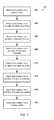
- FIG. 7is a process flow diagram of an embodiment method for cooling a compression molding device.
- exemplaryis used herein to mean “serving as an example, instance, or illustration.” Any implementation described herein as “exemplary” is not necessarily to be construed as preferred or advantageous over other implementations.
- Embodimentsprovide methods and devices for cooling a compression molding assembly, thereby enabling increased cycling speed and efficiency.
- Embodimentsprovide coolant flow paths through a mold assembly through which a coolant fluid (e.g., water) flows into and out of a cooling ring around the molding assembly's core.
- the coolant flow pathmay divide into several channels within and around the cooling ring to enable efficient heat transfer and more uniform thermal profiles within the mold assembly than achieved in conventional designs.
- the coolant flow pathmay include a series of stages with varying volumes or cross sectional dimensions configured to regulate the flow of coolant.
- Embodiment methods and devicesmay enable greater production rates with lower coolant flow rates.
- FIG. 1Ais a cross sectional view of an embodiment compression molding assembly 100 that may be used for molding plastic caps.
- Molding assembly 100may comprise an upper assembly 102 and a base assembly 104 .
- the upper assembly 102may include may include a stripper 29 , a tamper band core 13 , a thread core 12 , a cooling ring 11 , a center core 10 , and a mandrel 36 .
- the center core 10may contact and compress a plastic material (not shown).
- a cooling ring 11may be configured around the center core 10 .
- a first end of a thread core 12may be configured around the cooling ring 11 .
- the thread core 12 , cooling ring 11 , and center core 10may all be concentric about a central axis as shown in FIG. 1A .
- a second end of the thread core 12may be assembled about a mandrel 36 .
- the thread core 12is positioned within a tamper band core 13 which forms tamper bands of the caps.
- the tamper band core 13is optional, and an embodiment without this component is described below with reference to FIGS. 5 and 6 .
- the tamper band core 13may be assembled within a stripper 29 , which may push a formed cap from the mold assembly 100 after the cap is formed. In operation the base assembly 104 may move relative to upper assembly 102 to compress plastic material within the volume between the two assemblies.
- the base assembly 104may include a cavity 30 with a cavity bottom 32 .
- plastic materialmay be loaded within the cavity 30 and compressed by moving the upper or base assemblies relative to one another.
- the upper assembly 102is threaded into a carousel while the base assembly 104 is attached to a press mechanism (e.g., a hydraulic ram) that raises and lowers the base assembly with respect to the upper assembly 102 .
- the compressed plastic materialassumes the shape of the open space within the mold cavity between the base assembly 104 and upper assembly 102 .
- the compressed plastic materialfills the boundaries of the cavity 30 and cavity bottom 32 .
- the base assembly 104may also include an outer ring 31 and a cover plate 33 .
- the base assembly 104may be loaded onto an adapter 34 , which may be threaded into a support or press mechanism.
- a machine nut 35may include a lip that fits around the outer ring 31 and acts to retain the base assembly 104 with the support or press mechanism.
- the upper mold assembly 102 shown in FIG. 1Amay include a bubbler tube 14 and an air tube 15 within the mandrel 36 .
- the air tube 15 and the bubbler tube 14may be concentric about the longitudinal axis of the mandrel 36 with the air tube 15 disposed within the bubbler tube 14 .
- the air tube 15may extend to an air plug 16 within the center core 10 . Air pressure may be applied through the air tube 15 and into air plug 16 . During operation, air directed by the air plug 16 may be used to aid ejection of a molded plastic cap off of the center core 10 , such as by preventing formation of a vacuum between the molded cap and the upper assembly 102 .
- Coolantsuch as water or other fluids
- the bubbler inlet 21may be supplied through the bubbler inlet 21 .
- the bubbler inletmay be defined by interior surfaces of the bubbler tube 14 and exterior surfaces of the air tube 15 .
- the bubbler tube 14may be configured to keep air and other gases out of the coolant.
- Coolantmay flow from the bubbler inlet 21 to a plurality of center core inlets 22 .
- the multiple center core inlets 22may be defined by surfaces inside the center core 10 .
- coolantmay flow from the center core inlets 22 into internal channels 23 adjacent the cooling ring 11 , with the internal channels 23 defined by the outer surface of the center core and a plurality of grooves in the inner surface of the cooling ring 11 .
- Coolantmay flow then into traversing channels 24 defined by a plurality of holes extending radially from an inner surface to an outer surface of the cooling ring 11 .
- the orientation of the grooves forming the internal channels 23 and the traversing channels 24 in the cooling ring 11are described in more detail below with reference to FIGS. 2 and 3 .
- the assembly 100may also include a number of O-ring seals between the various parts.
- the center core O-ring 17forms a seal between the center core 10 and the cooling ring 11 preventing leakage of coolant flowing in internal channels 23 or entering traverse channels 24 .
- the cooling ring O-ring 18forms a seal between the thread core 12 and the cooling ring 11 preventing leakage of coolant flowing in external channels 25 or exiting traverse channels 24 .
- a mandrel O-ring 19may form a seal at the top of the thread core 12 .
- An air plug O-ring 20may prevent coolant in the center core inlets 22 from entering the air plug and prevent air from entering the coolant.
- FIG. 1Bis a close up view of a portion of the assembly 100 shown FIG. 1A which better illustrates the coolant flow path 112 through the assembly in this embodiment.
- the coolant flow path 112is defined by several surfaces of the center core 10 , the cooling ring 11 , and the thread core 12 . Coolant flowing into the illustrated embodiment assembly, shown with a plus sign cross hatch, passes down through the bubbler tube 14 into the center core inlets 22 within the center core 10 . Coolant flows out of the center core inlets 22 into the internal channels 23 .
- the internal channels 23are formed in the volume between longitudinal grooves in the inner surface of the cooling ring 11 and the outer surface of the center core 10 .
- Coolantflows from the internal channels 23 into the traversing channels 24 that traverse the wall of the cooling ring 11 from the inner surface of the cooling ring 11 to the outer surface of the cooling ring 11 .
- the coolantmay flow around the circumference of the cooling ring 11 in arcuate channels which direct the coolant to a return flow path through longitudinal flow paths formed by longitudinal grooves in the outer surface of the cooling ring 11 , with the flow path being defined by the groove structure and an inner surface of the thread core 12 .
- FIG. 1Balso illustrates features of the thread core 12 .
- the thread core 12may include external threads 106 configured for molding the closure threads of caps.
- the thread core 12may also include internal assembly threads 110 .
- the center core 10may be assembled through the cooling ring 11 and engage the assembly threads 110 of the thread core 12 . Such assembly may hold the three pieces together and form the coolant channels there between. When assembled, a plug seal gap 108 between the cooling ring 11 and the center core 10 is formed into which compressed plastic material flows during pressing operations.
- FIGS. 2 and 3show the cooling ring 11 in isolation.
- the internal flow channels 23may be partially defined by grooves in the inner surface of the cooling ring 11 .
- the other surface defining the internal channels 23is the outer surface of the center core 10 when the center core 10 and cooling ring 11 are assembled together.
- the coolantflows vertically through the internal channels 23 formed between the center core 10 and the cooling ring 11 in the internal channels 23 , and then radially outward through a plurality of traversing channels 24 that are holes passing through the wall of the cooling ring 11 .
- FIG. 3shows these arcuate channels 25 formed by grooves in the outside surface of cooling ring 11 .
- the other surface defining the arcuate flow channelsis the inside of the thread core 12 when the thread core 12 and cooling ring 11 are assembled together.
- These external longitudinal flow channels 26are defined on one side by the longitudinal grooves labeled 26 on the outside of the cooling ring 11 and by the interior surfaces of the thread core 12 when the cooling ring 11 and thread core 12 are assembled together.
- FIGS. 2 and 3show an embodiment of the cooling ring 11 in which the ring is formed as a single component.
- the cooling ringmay be an assembly comprising a plurality of components.
- a plurality of componentsmay be joined or sealed together, such as with additional O-rings, to form a composite cooling ring.
- One or more of the plurality of componentsmay define the various channels as described with regard to the cooling ring 11 .
- FIG. 4illustrates the same exemplary molding assembly 100 as FIG. 1A but at a different angle of rotation about the longitudinal axis in order to reveal the flow path of coolant exiting the mold assembly 100 .
- the assembly 100is shown in a first orientation that shows the coolant flows into the assembly.
- the assemblyis rotated thirty degrees to show the coolant exit flow paths which are thirty degrees apart from the inner flow paths 23 about the cooling ring 11 .
- coolantexits the traversing channels 24 and flows through the arcuate channels 25 around the cooling ring 11 before reaching external channels 26 where the flow is directed upward along the outer surface of the cooling ring 11 .
- FIGS. 2 and 3details on the grooves in the cooling ring forming the external flow channels 26 are shown in FIGS. 2 and 3 , including how these flow channels are offset from each other by an angle about the longitudinal axis. In the embodiment illustrated in the figures, this offset angle is approximately thirty degrees, but the angle may vary depending on the number of coolant channels in each stage of the assembly.
- Coolantmay flow from the external channels 26 into center core outlets 27 .
- Multiple center core outlets 27may be defined by surfaces inside the center core 10 , similar to the center core inlets 22 .
- the center core outlets 27lead the coolant flow to the bubbler outlet 28 which directs the coolant flow out of the molding assembly 100 .
- the bubbler outlet 28 flow pathmay pass through the volume defined by an outer surface of the bubbler tube 14 and an inner surface of the mandrel 36 .
- coolantcontacts the center core 10 , cooling ring 11 , and thread core 12 while passing through various volumes of the coolant flow path 112 .
- Thisenables heat to be transferred from these parts to the coolant and removed from the assembly 100 as coolant flows out the bubbler outlet 28 .
- stages in the coolant flow path 112may include multiple channels. Multiple channels per stage may increase surface area contact with the parts and improve heat transfer.
- the multiple channels and flow pathsmay be designed or arranged to ensure an even heat distribution within the parts of the mold assembly, thereby preventing local hotspots from negatively affecting performance of the molding assembly 100 during high volume molding operations.
- the various channels of the coolant flow path 112may be sized with cross sectional areas designed to impart desirable coolant flow behavior.
- the combined cross sectional area of the plurality of center core inlets 22may be greater than the cross sectional area of the bubbler inlet 21 .
- the combined cross sectional area of the internal channels 23may be less than the cross sectional area of the bubbler inlet 21 .
- the combined cross sectional area of the external channels 26may be less than the combined area of the internal channels 23 .
- the ratios of cross sectional areas between portions of the flow pathmay be configured to control coolant flow and thereby improve heat transfer.
- Each successive element or stagemay have a flow area ratio to the preceding stage configured to improve heat transfer in each stage.
- Each flow area ratiomay be relative to the cross sectional area of the bubbler inlet 21 or to another stage in the coolant flow path 112 .
- the center core inlets 23may have a greater combined cross sectional area than other portions of the assembly.
- the subsequent portions of the coolant flow path through the upper assembly 102may have a smaller combined cross sectional area corresponding with increased flow velocity and lower pressure with constant volumetric flow. Therefore, the coolant may experience a pressure gradient along the coolant flow path 112 . This pressure gradient can be used to regulate the coolant flow through the upper assembly 102 and improve heat transfer from the mold elements to the coolant.
- Alternate embodimentsmay include differently shaped center cores, cooling rings, or thread cores. These pieces may define different amounts or shapes of flow paths or channels. Embodiments that require more cooling may include a greater number of coolant channels. Alternatively, embodiments that require less cooling may include less coolant channels and thereby reduce the amount of coolant used. In further embodiments, some components illustrated and described herein as separate elements may be combined into single components exhibiting the same or similar features and performing the same or similar functions. Also, components illustrated and described herein as unitary structures may be formed as assemblies of multiple components.
- FIG. 5illustrates an alternate embodiment molding assembly.
- the embodiment assembly illustrated in FIG. 5includes many of the same elements as the mold assembly 100 described above with reference FIGS. 1A, 1B 4 .
- the central core 10 and cooling ring 11are configured differently so that the bottom of the center core 10 extends all the way to the thread core 12 .
- This embodimentmay not include the plug seal gaps 108 shown in FIG. 1B , and therefore the caps produced will not have a plug seal.
- a plug sealmay be a seal to fit inside the lip of a container coupled with a cap.
- the cooling ring 11may not directly contact the plastic material being molded. Heat may be transferred from the plastic material to the cooling ring 11 indirectly via the center core 10 or the thread core 12 .
- FIG. 6illustrates the embodiment of FIG. 5 rotated thirty degrees to show the coolant's exit path from the upper assembly 102 .
- the assemblymay not include plug seal gaps 108 and the cooling ring 11 may not be configured to contact the plastic material being molded.
- FIG. 7illustrates an embodiment method 200 in which fluid coolant is directed into various elements of the coolant flow path 112 .
- fluid coolantmay be directed into or through a bubbler input in step 202 , through a plurality of center core inlets in step 204 , through a longitudinal flow path defined by plurality of internal grooves in the cooling ring in step 206 , through a plurality of holes through the cooling ring in step 208 , circumferentially through flow paths defined by a plurality of arcuate grooves in the cooling ring in step 210 , through a longitudinal flow path defined by a plurality of external grooves in the cooling ring in step 212 , through a plurality of center core outlets in step 214 , and out of the assembly through a bubbler outlet in step 216 .
Landscapes
- Engineering & Computer Science (AREA)
- Mechanical Engineering (AREA)
- Manufacturing & Machinery (AREA)
- Physics & Mathematics (AREA)
- Fluid Mechanics (AREA)
- Moulds For Moulding Plastics Or The Like (AREA)
- Casting Or Compression Moulding Of Plastics Or The Like (AREA)
Abstract
Description
- 10 Center Core
- 11 Cooling Ring
- 12 Thread Core
- 13 Tamper Band Core
- 14 Bubbler Tube
- 15 Air Tube
- 16 Air Plug
- 17 O-Ring—Center Core
- 18 O-Ring—Cooling Ring
- 19 O-Ring—Mandrel
- 20 O-Ring—Air Plug
- 21 Coolant Flow Path—Bubbler Inlet
- 22 Coolant Flow Path—Center Core Inlet
- 23 Coolant Flow Path—Internal Channels in Cooling Ring
- 24 Coolant Flow Path—Traversing Channels in Cooling Ring
- 25 Coolant Flow Path—Arcuate Channels in Cooling Ring
- 26 Coolant Flow Path—External Channels in Cooling Ring
- 27 Coolant Flow Path—Center Core Outlet
- 28 Coolant Flow Path—Bubbler Outlet
- 29 Stripper
- 30 Cavity
- 31 Outer Ring
- 32 Cavity Bottom
- 33 Cover Plate
- 34 Adapter
- 35 Machine Nut
- 36 Mandrel
- 100 Compression Molding Assembly
- 102 Upper Assembly
- 104 Base Assembly
- 106 External Threads of the Thread Core
- 108 Plug Seal Gaps
- 110 Internal Assembly Threads of the Thread Core
- 112 Coolant Flow Path
Claims (26)
Priority Applications (1)
| Application Number | Priority Date | Filing Date | Title |
|---|---|---|---|
| US14/049,568US9475246B2 (en) | 2011-05-24 | 2013-10-09 | Method of molding and mold with succesive stage cooling channels |
Applications Claiming Priority (3)
| Application Number | Priority Date | Filing Date | Title |
|---|---|---|---|
| US13/114,327US20120301570A1 (en) | 2011-05-24 | 2011-05-24 | Compression Molding with Successive Cooling Channels |
| US13/277,022US8585392B2 (en) | 2011-05-24 | 2011-10-19 | Compression molding with successive stage cooling channels |
| US14/049,568US9475246B2 (en) | 2011-05-24 | 2013-10-09 | Method of molding and mold with succesive stage cooling channels |
Related Parent Applications (1)
| Application Number | Title | Priority Date | Filing Date |
|---|---|---|---|
| US13/277,022ContinuationUS8585392B2 (en) | 2011-05-24 | 2011-10-19 | Compression molding with successive stage cooling channels |
Publications (2)
| Publication Number | Publication Date |
|---|---|
| US20140035194A1 US20140035194A1 (en) | 2014-02-06 |
| US9475246B2true US9475246B2 (en) | 2016-10-25 |
Family
ID=47217972
Family Applications (2)
| Application Number | Title | Priority Date | Filing Date |
|---|---|---|---|
| US13/277,022Active2032-02-01US8585392B2 (en) | 2011-05-24 | 2011-10-19 | Compression molding with successive stage cooling channels |
| US14/049,568Active2032-10-27US9475246B2 (en) | 2011-05-24 | 2013-10-09 | Method of molding and mold with succesive stage cooling channels |
Family Applications Before (1)
| Application Number | Title | Priority Date | Filing Date |
|---|---|---|---|
| US13/277,022Active2032-02-01US8585392B2 (en) | 2011-05-24 | 2011-10-19 | Compression molding with successive stage cooling channels |
Country Status (12)
| Country | Link |
|---|---|
| US (2) | US8585392B2 (en) |
| EP (1) | EP2714356B1 (en) |
| JP (1) | JP6085295B2 (en) |
| KR (1) | KR101946589B1 (en) |
| CN (1) | CN103946001B (en) |
| AU (1) | AU2012259212B2 (en) |
| CA (1) | CA2836572C (en) |
| ES (1) | ES2568066T3 (en) |
| HU (1) | HUE028491T2 (en) |
| MX (1) | MX344506B (en) |
| WO (1) | WO2012162035A2 (en) |
| ZA (1) | ZA201309266B (en) |
Families Citing this family (12)
| Publication number | Priority date | Publication date | Assignee | Title |
|---|---|---|---|---|
| US8585392B2 (en)* | 2011-05-24 | 2013-11-19 | F&S Tool, Inc. | Compression molding with successive stage cooling channels |
| US9248597B2 (en)* | 2012-04-02 | 2016-02-02 | Progressive Components International Corporation | Bubbler base |
| US10005214B1 (en)* | 2014-07-03 | 2018-06-26 | Plastek Industries, Inc. | Cap manufacture methods and apparatus |
| MX2017008332A (en) | 2014-12-22 | 2017-11-28 | Graham Packaging Co | Deformation-resistant container with panel indentations. |
| IT201600076240A1 (en)* | 2016-07-20 | 2018-01-20 | Sacmi | PUNCH FOR COMPRESSION MOLDS |
| US20210245238A1 (en)* | 2018-08-24 | 2021-08-12 | Grouper Casting, Llc | Molding tool with high-performance cooling system |
| CN113329859A (en) | 2018-12-07 | 2021-08-31 | 纳格·南科国际有限公司 | Mandrel assembly for blow molding having multiple temperature zones |
| EP4403145A3 (en) | 2020-06-03 | 2024-10-02 | Medtronic, Inc. | Delivery device having a control release shaft for improved positioning of a transcatheter heart valve |
| WO2021247351A1 (en) | 2020-06-04 | 2021-12-09 | Medtronic, Inc. | Delivery system having a split distal tip for improved positioning of a transcatheter heart valve |
| US11794938B2 (en) | 2021-09-02 | 2023-10-24 | Graham Packaging Company, L.P. | Container finish having improved rim planarity |
| CN114472969B (en)* | 2022-03-25 | 2023-04-18 | 苏州凯雷特精密机械有限公司 | Drilling device for aerospace parts |
| US20230364845A1 (en)* | 2022-05-16 | 2023-11-16 | Engineered Profiles LLC | Clad sizer for an extrusion machine |
Citations (59)
| Publication number | Priority date | Publication date | Assignee | Title |
|---|---|---|---|---|
| US2828509A (en)* | 1954-11-03 | 1958-04-01 | Crown Machine And Tool Company | Plastic molding machines |
| US3373479A (en) | 1965-03-25 | 1968-03-19 | Aluminum Co Of America | Method for making molded articles |
| US3660001A (en) | 1968-11-06 | 1972-05-02 | George L Roehr | Molding apparatus with positive collapse core |
| US3913660A (en) | 1972-11-14 | 1975-10-21 | Schmidt Gmbh Karl | Chill mold for casting pistons |
| US4091069A (en)* | 1977-02-17 | 1978-05-23 | Logic Devices, Inc. | Method and apparatus for venting entrapped air in mold cavities |
| US4130264A (en) | 1977-10-26 | 1978-12-19 | Geyer & Co. | Expandable core for injection molding |
| JPS57156231A (en) | 1981-03-23 | 1982-09-27 | Hitachi Ltd | Split core of mold for injection molding |
| JPS60112413A (en) | 1983-11-25 | 1985-06-18 | Daiichi Gaiyaa Kk | Pop-up core |
| US4533312A (en) | 1982-12-27 | 1985-08-06 | Holdt J W Von | Simplified collapsible mold core |
| US4541605A (en) | 1983-02-16 | 1985-09-17 | Daiichi-Geyer Kabushiki Kaisha | Metal mold device |
| US4622001A (en) | 1985-03-12 | 1986-11-11 | Electra Form, Inc. | Cavity cooling system |
| JPS62279914A (en) | 1986-05-28 | 1987-12-04 | Cosmo Seimitsu:Kk | Manufacturing equipment for article having undercut on inside |
| US4731014A (en) | 1986-03-12 | 1988-03-15 | Holdt J W Von | Rear opening mold |
| US4771981A (en) | 1985-08-30 | 1988-09-20 | R. Clarke & Co. (Moulds) Limited | Collapsible mould core |
| US4861257A (en) | 1987-06-05 | 1989-08-29 | Toto Ltd. | Core structure of molding apparatus |
| US4915609A (en) | 1987-10-16 | 1990-04-10 | Klevotec, Gesellschaft Fur Rechnergestutzte Systemanwendungen Gmbh Co. K.G. | Sintering device for blanks of foamable plastics with undercuts |
| US4966544A (en)* | 1987-07-22 | 1990-10-30 | Fuji Photo Film Co., Ltd. | Injection mold having cooling fins |
| US5096410A (en) | 1991-02-19 | 1992-03-17 | Demetre Loulourgas | Water jacketed sprue bushing |
| US5114655A (en) | 1989-08-17 | 1992-05-19 | Cole Machine & Mfg. Co. | Method and apparatus for injection molding |
| JPH0557760A (en) | 1991-09-03 | 1993-03-09 | Copal Co Ltd | Injection mold having undercut part |
| US5383780A (en) | 1993-09-27 | 1995-01-24 | Husky Injection Molding Systems Ltd. | Apparatus for forming threaded molded article |
| US5403179A (en) | 1993-10-29 | 1995-04-04 | Ramsey; William C. | Collapsible mold core assembly |
| US5630977A (en) | 1993-12-23 | 1997-05-20 | Roehr Tool Corporation | Injection molding method and system with expandable cavity element |
| US5700415A (en) | 1994-10-19 | 1997-12-23 | Toska Co., Ltd. | Method of molding synthetic resin and apparatus for use therein |
| US5798074A (en) | 1993-09-27 | 1998-08-25 | Husky Injection Molding Systems Ltd. | Process for forming a threaded molded plastic article |
| US5855933A (en)* | 1992-10-16 | 1999-01-05 | Innova Zug Ag | Temperature-controllable tool or mold for producing plastic moldings and process for making such tools or molds |
| KR19990018904U (en) | 1997-11-14 | 1999-06-05 | 오상수 | Cooling water circulation structure of mold |
| US5925303A (en) | 1995-02-09 | 1999-07-20 | Unique Mould Makers Limited | Process for forming seamless molded skirt |
| US5935621A (en)* | 1997-01-24 | 1999-08-10 | Mold-Masters Limited | Injection molding apparatus having a cooled core |
| US6017209A (en)* | 1998-02-02 | 2000-01-25 | Mold-Masters Limited | Injection molding cooled gate insert |
| US6030202A (en)* | 1998-02-02 | 2000-02-29 | Mold-Masters Limited | Injection molding three portion gate and cavity insert |
| US6077067A (en)* | 1998-12-07 | 2000-06-20 | Gellert; Jobst Ulrich | Injection molding apparatus having a cooling core with a ribbed cap |
| US6079972A (en)* | 1998-12-07 | 2000-06-27 | Gellert; Jobst Ulrich | Injection molding cooling core having spiral grooves |
| US6099785A (en) | 1998-03-17 | 2000-08-08 | Schweigert; Lothar | Method for injection molding plastic closures |
| WO2000048815A1 (en) | 1999-02-17 | 2000-08-24 | Gellert Jobst U | Injection molding cooled cavity insert |
| US6168740B1 (en)* | 1997-04-16 | 2001-01-02 | Husky Injection Molding Systems Ltd. | Partial crystallization method of amorphous plastic articles |
| US6220850B1 (en) | 1999-02-16 | 2001-04-24 | Husky Injection Molding Systems Ltd. | Mold gate insert |
| US6276922B1 (en)* | 1999-08-24 | 2001-08-21 | Husky Injection Molding Systems Ltd. | Core fluid velocity inducer |
| US20020001637A1 (en) | 2000-06-28 | 2002-01-03 | Saad Taha | Container closure and mold assembly therefor |
| US6506330B1 (en) | 1998-03-17 | 2003-01-14 | Lothar Schweigert | Apparatus and method for molding plastic closures |
| US20030064128A1 (en)* | 2001-09-07 | 2003-04-03 | Byrnes Dennis S. | Mold with contoured cooling channels |
| USRE38265E1 (en)* | 1997-01-24 | 2003-10-07 | Mold-Masters Limited | Injection molding apparatus having a cooled core |
| KR20050071679A (en) | 2002-11-12 | 2005-07-07 | 고든 엠 펜더그래프트 | A vacuum cast ceramic fiber insulated band having heating and cooling elements |
| US20050194709A1 (en) | 2003-08-22 | 2005-09-08 | Graham Packaging Company, L.P. | Modified injection takeout tube |
| US20070092596A1 (en) | 2005-10-20 | 2007-04-26 | Husky Injection Molding Systems Ltd. | Apparatus for cooling mold insert |
| US7252497B2 (en) | 2005-03-10 | 2007-08-07 | Husky Injection Molding Systems Ltd. | Post-molding molded article conditioning apparatus with a selectively controlled transfer flow structure |
| US20070212443A1 (en) | 2006-03-08 | 2007-09-13 | Husky Injection Molding Systems Ltd. | Injection mold |
| US7293341B2 (en) | 2005-02-18 | 2007-11-13 | Progressive Components International Corporation | Collapsible core assembly for a molding apparatus |
| DE102006028149A1 (en) | 2006-06-16 | 2007-12-20 | Mht Mold & Hotrunner Technology Ag | Formnestkavität with decoupled cooling duct guide |
| US20080087627A1 (en) | 2004-10-13 | 2008-04-17 | Sacmi Cooperative Meccanici Imola Sociea' Cooperativa | Cap For Closing Containers and Apparatus for Forming Liners |
| US7425293B2 (en) | 2003-01-20 | 2008-09-16 | Sacmi Cooperativa Meccanici Imola Soc. Coop. A.R.L. | Method for forming articles by compression moulding |
| US20090152770A1 (en) | 2007-08-07 | 2009-06-18 | Canon Virginia Inc. | Mechanically collapsible core for injection molding |
| US20090324770A1 (en) | 2006-05-06 | 2009-12-31 | Mht Mold & Hotrunner Technology Ag | Bottom Insert With Heat Insulation |
| US7645132B2 (en) | 2007-09-07 | 2010-01-12 | Husky Injection Molding Systems Ltd. | Mold insert and mold stack for use with molding machine |
| US20100183763A1 (en) | 2009-01-22 | 2010-07-22 | Mold-Masters (2007) Limited | Injection Molding Apparatus |
| US7798806B2 (en) | 2006-05-06 | 2010-09-21 | Mold & Hotrunner Technology Ag | Two-piece bottom insert for a mold cavity |
| US7934920B2 (en) | 2005-06-17 | 2011-05-03 | Rexam Closure Systems Inc. | Molding machine |
| US20120301572A1 (en)* | 2011-05-24 | 2012-11-29 | F&S Tool, Inc. | Compression Molding with Successive Stage Cooling Channels |
| US20150044323A1 (en)* | 2012-03-21 | 2015-02-12 | Sacmi Cooperativa Meccanici Imola Societa' Cooperativa | Male mould element |
Family Cites Families (4)
| Publication number | Priority date | Publication date | Assignee | Title |
|---|---|---|---|---|
| JPH09262870A (en)* | 1996-01-23 | 1997-10-07 | Sekisui Chem Co Ltd | Injection mold and its production |
| US7234930B2 (en)* | 2004-06-14 | 2007-06-26 | Husky Injection Molding Systems Ltd. | Cooling circuit for cooling neck ring of preforms |
| ITMO20050224A1 (en)* | 2005-09-07 | 2007-03-08 | Sacmi | MOLDS FOR MOLDING OF PLASTIC ITEMS AND METHOD TO PRODUCE A MOLD ELEMENT |
| JP2009196138A (en)* | 2008-02-20 | 2009-09-03 | Seiko Epson Corp | Apparatus for injection moulding and cooling method in apparatus for injection moulding |
- 2011
- 2011-10-19USUS13/277,022patent/US8585392B2/enactiveActive
- 2012
- 2012-05-15CACA2836572Apatent/CA2836572C/enactiveActive
- 2012-05-15EPEP12790229.4Apatent/EP2714356B1/enactiveActive
- 2012-05-15HUHUE12790229Apatent/HUE028491T2/enunknown
- 2012-05-15KRKR1020137033950Apatent/KR101946589B1/enactiveActive
- 2012-05-15ESES12790229.4Tpatent/ES2568066T3/enactiveActive
- 2012-05-15AUAU2012259212Apatent/AU2012259212B2/enactiveActive
- 2012-05-15JPJP2014512878Apatent/JP6085295B2/enactiveActive
- 2012-05-15MXMX2013013506Apatent/MX344506B/enactiveIP Right Grant
- 2012-05-15WOPCT/US2012/037985patent/WO2012162035A2/enactiveApplication Filing
- 2012-05-15CNCN201280030178.XApatent/CN103946001B/enactiveActive
- 2013
- 2013-10-09USUS14/049,568patent/US9475246B2/enactiveActive
- 2013-12-09ZAZA2013/09266Apatent/ZA201309266B/enunknown
Patent Citations (70)
| Publication number | Priority date | Publication date | Assignee | Title |
|---|---|---|---|---|
| US2828509A (en)* | 1954-11-03 | 1958-04-01 | Crown Machine And Tool Company | Plastic molding machines |
| US3373479A (en) | 1965-03-25 | 1968-03-19 | Aluminum Co Of America | Method for making molded articles |
| US3660001A (en) | 1968-11-06 | 1972-05-02 | George L Roehr | Molding apparatus with positive collapse core |
| US3913660A (en) | 1972-11-14 | 1975-10-21 | Schmidt Gmbh Karl | Chill mold for casting pistons |
| US4091069A (en)* | 1977-02-17 | 1978-05-23 | Logic Devices, Inc. | Method and apparatus for venting entrapped air in mold cavities |
| US4130264A (en) | 1977-10-26 | 1978-12-19 | Geyer & Co. | Expandable core for injection molding |
| JPS57156231A (en) | 1981-03-23 | 1982-09-27 | Hitachi Ltd | Split core of mold for injection molding |
| US4533312A (en) | 1982-12-27 | 1985-08-06 | Holdt J W Von | Simplified collapsible mold core |
| US4541605A (en) | 1983-02-16 | 1985-09-17 | Daiichi-Geyer Kabushiki Kaisha | Metal mold device |
| JPS60112413A (en) | 1983-11-25 | 1985-06-18 | Daiichi Gaiyaa Kk | Pop-up core |
| US4622001A (en) | 1985-03-12 | 1986-11-11 | Electra Form, Inc. | Cavity cooling system |
| US4771981A (en) | 1985-08-30 | 1988-09-20 | R. Clarke & Co. (Moulds) Limited | Collapsible mould core |
| US4731014A (en) | 1986-03-12 | 1988-03-15 | Holdt J W Von | Rear opening mold |
| JPS62279914A (en) | 1986-05-28 | 1987-12-04 | Cosmo Seimitsu:Kk | Manufacturing equipment for article having undercut on inside |
| US4861257A (en) | 1987-06-05 | 1989-08-29 | Toto Ltd. | Core structure of molding apparatus |
| US4966544A (en)* | 1987-07-22 | 1990-10-30 | Fuji Photo Film Co., Ltd. | Injection mold having cooling fins |
| US4915609A (en) | 1987-10-16 | 1990-04-10 | Klevotec, Gesellschaft Fur Rechnergestutzte Systemanwendungen Gmbh Co. K.G. | Sintering device for blanks of foamable plastics with undercuts |
| US5114655A (en) | 1989-08-17 | 1992-05-19 | Cole Machine & Mfg. Co. | Method and apparatus for injection molding |
| US5096410A (en) | 1991-02-19 | 1992-03-17 | Demetre Loulourgas | Water jacketed sprue bushing |
| JPH0557760A (en) | 1991-09-03 | 1993-03-09 | Copal Co Ltd | Injection mold having undercut part |
| US5855933A (en)* | 1992-10-16 | 1999-01-05 | Innova Zug Ag | Temperature-controllable tool or mold for producing plastic moldings and process for making such tools or molds |
| US5798074A (en) | 1993-09-27 | 1998-08-25 | Husky Injection Molding Systems Ltd. | Process for forming a threaded molded plastic article |
| US5383780A (en) | 1993-09-27 | 1995-01-24 | Husky Injection Molding Systems Ltd. | Apparatus for forming threaded molded article |
| US5403179A (en) | 1993-10-29 | 1995-04-04 | Ramsey; William C. | Collapsible mold core assembly |
| US5630977A (en) | 1993-12-23 | 1997-05-20 | Roehr Tool Corporation | Injection molding method and system with expandable cavity element |
| US5700415A (en) | 1994-10-19 | 1997-12-23 | Toska Co., Ltd. | Method of molding synthetic resin and apparatus for use therein |
| US5925303A (en) | 1995-02-09 | 1999-07-20 | Unique Mould Makers Limited | Process for forming seamless molded skirt |
| US5935621A (en)* | 1997-01-24 | 1999-08-10 | Mold-Masters Limited | Injection molding apparatus having a cooled core |
| USRE38265E1 (en)* | 1997-01-24 | 2003-10-07 | Mold-Masters Limited | Injection molding apparatus having a cooled core |
| EP1825988A1 (en) | 1997-04-16 | 2007-08-29 | Husky Injection Molding Systems Ltd. | Injection molding apparatus with cooled core |
| US6168740B1 (en)* | 1997-04-16 | 2001-01-02 | Husky Injection Molding Systems Ltd. | Partial crystallization method of amorphous plastic articles |
| US20010016239A1 (en) | 1997-04-16 | 2001-08-23 | Husky Injection Molding Systems Ltd. | Partial crystallization method and apparatus of amorphous plastic articles |
| KR19990018904U (en) | 1997-11-14 | 1999-06-05 | 오상수 | Cooling water circulation structure of mold |
| US6017209A (en)* | 1998-02-02 | 2000-01-25 | Mold-Masters Limited | Injection molding cooled gate insert |
| US6030202A (en)* | 1998-02-02 | 2000-02-29 | Mold-Masters Limited | Injection molding three portion gate and cavity insert |
| US6099785A (en) | 1998-03-17 | 2000-08-08 | Schweigert; Lothar | Method for injection molding plastic closures |
| US6506330B1 (en) | 1998-03-17 | 2003-01-14 | Lothar Schweigert | Apparatus and method for molding plastic closures |
| US6077067A (en)* | 1998-12-07 | 2000-06-20 | Gellert; Jobst Ulrich | Injection molding apparatus having a cooling core with a ribbed cap |
| US6079972A (en)* | 1998-12-07 | 2000-06-27 | Gellert; Jobst Ulrich | Injection molding cooling core having spiral grooves |
| US6220850B1 (en) | 1999-02-16 | 2001-04-24 | Husky Injection Molding Systems Ltd. | Mold gate insert |
| US6488881B2 (en) | 1999-02-17 | 2002-12-03 | Jobst Ulrich Gellert | Injection molding cooled cavity insert |
| WO2000048815A1 (en) | 1999-02-17 | 2000-08-24 | Gellert Jobst U | Injection molding cooled cavity insert |
| US6176700B1 (en) | 1999-02-17 | 2001-01-23 | Jobst Ulrich Gellert | Injection molding cooled cavity insert |
| US6276922B1 (en)* | 1999-08-24 | 2001-08-21 | Husky Injection Molding Systems Ltd. | Core fluid velocity inducer |
| US20020001637A1 (en) | 2000-06-28 | 2002-01-03 | Saad Taha | Container closure and mold assembly therefor |
| US6551093B2 (en) | 2000-06-28 | 2003-04-22 | Saad Taha | Mold assembly for a container closure |
| US20030064128A1 (en)* | 2001-09-07 | 2003-04-03 | Byrnes Dennis S. | Mold with contoured cooling channels |
| KR20050071679A (en) | 2002-11-12 | 2005-07-07 | 고든 엠 펜더그래프트 | A vacuum cast ceramic fiber insulated band having heating and cooling elements |
| US7425293B2 (en) | 2003-01-20 | 2008-09-16 | Sacmi Cooperativa Meccanici Imola Soc. Coop. A.R.L. | Method for forming articles by compression moulding |
| US7232306B2 (en) | 2003-08-22 | 2007-06-19 | Graham Packaging Company, Lp | Modified injection takeout tube |
| US20050194709A1 (en) | 2003-08-22 | 2005-09-08 | Graham Packaging Company, L.P. | Modified injection takeout tube |
| US20080087627A1 (en) | 2004-10-13 | 2008-04-17 | Sacmi Cooperative Meccanici Imola Sociea' Cooperativa | Cap For Closing Containers and Apparatus for Forming Liners |
| US7293341B2 (en) | 2005-02-18 | 2007-11-13 | Progressive Components International Corporation | Collapsible core assembly for a molding apparatus |
| US7252497B2 (en) | 2005-03-10 | 2007-08-07 | Husky Injection Molding Systems Ltd. | Post-molding molded article conditioning apparatus with a selectively controlled transfer flow structure |
| US7364688B2 (en) | 2005-03-10 | 2008-04-29 | Husky Injection Molding Systems Ltd. | Method for post-molding a molded article conditioning apparatus with a selectively controlled transfer flow structure |
| US7934920B2 (en) | 2005-06-17 | 2011-05-03 | Rexam Closure Systems Inc. | Molding machine |
| US20070092596A1 (en) | 2005-10-20 | 2007-04-26 | Husky Injection Molding Systems Ltd. | Apparatus for cooling mold insert |
| US7361009B2 (en) | 2005-10-20 | 2008-04-22 | Husky Injection Molding Systems Ltd. | Mold cavity insert for use in an injection mold |
| US20070212443A1 (en) | 2006-03-08 | 2007-09-13 | Husky Injection Molding Systems Ltd. | Injection mold |
| US7381049B2 (en) | 2006-03-08 | 2008-06-03 | Husky Injection Molding Systems Ltd. | Injection mold |
| US20090324770A1 (en) | 2006-05-06 | 2009-12-31 | Mht Mold & Hotrunner Technology Ag | Bottom Insert With Heat Insulation |
| US7798806B2 (en) | 2006-05-06 | 2010-09-21 | Mold & Hotrunner Technology Ag | Two-piece bottom insert for a mold cavity |
| US20100297287A1 (en) | 2006-06-16 | 2010-11-25 | Mht Mold & Hotrunner Technology Ag | Mould cavity with decoupled cooling-channel routing |
| DE102006028149A1 (en) | 2006-06-16 | 2007-12-20 | Mht Mold & Hotrunner Technology Ag | Formnestkavität with decoupled cooling duct guide |
| US20090152770A1 (en) | 2007-08-07 | 2009-06-18 | Canon Virginia Inc. | Mechanically collapsible core for injection molding |
| US7645132B2 (en) | 2007-09-07 | 2010-01-12 | Husky Injection Molding Systems Ltd. | Mold insert and mold stack for use with molding machine |
| US20100183763A1 (en) | 2009-01-22 | 2010-07-22 | Mold-Masters (2007) Limited | Injection Molding Apparatus |
| US20120301572A1 (en)* | 2011-05-24 | 2012-11-29 | F&S Tool, Inc. | Compression Molding with Successive Stage Cooling Channels |
| US8585392B2 (en)* | 2011-05-24 | 2013-11-19 | F&S Tool, Inc. | Compression molding with successive stage cooling channels |
| US20150044323A1 (en)* | 2012-03-21 | 2015-02-12 | Sacmi Cooperativa Meccanici Imola Societa' Cooperativa | Male mould element |
Non-Patent Citations (5)
| Title |
|---|
| "Cooling System Modeling Techniques", Advanced CAE Technology Inc, 1986-1998, 13 pages. http://www.dc.engr.scu.edu/cmdoc/cl-doc/a-modeli.htm.* |
| Chinese Office Action CN Application No. 201280030178.X issued May 25, 2016. |
| Extended European Search Report issued for European Application No. 12790229, mailed on Oct. 6, 2014. |
| International Preliminary Report on Patentability; International Application No. PCT/US2012/037985; mailed Dec. 5, 2013. |
| International Search Report and Written Opinion issued in PCT Application No. PCT/US2012/037985, mailed on Jan. 31, 2013. |
Also Published As
| Publication number | Publication date |
|---|---|
| CA2836572C (en) | 2019-03-19 |
| CN103946001A (en) | 2014-07-23 |
| HUE028491T2 (en) | 2016-12-28 |
| US8585392B2 (en) | 2013-11-19 |
| KR101946589B1 (en) | 2019-04-22 |
| EP2714356A4 (en) | 2014-11-05 |
| EP2714356B1 (en) | 2016-01-13 |
| US20140035194A1 (en) | 2014-02-06 |
| ZA201309266B (en) | 2014-08-27 |
| HK1199227A1 (en) | 2015-06-26 |
| US20120301572A1 (en) | 2012-11-29 |
| WO2012162035A2 (en) | 2012-11-29 |
| AU2012259212B2 (en) | 2016-08-25 |
| CA2836572A1 (en) | 2012-11-29 |
| ES2568066T3 (en) | 2016-04-27 |
| JP2014517783A (en) | 2014-07-24 |
| CN103946001B (en) | 2017-03-15 |
| EP2714356A2 (en) | 2014-04-09 |
| JP6085295B2 (en) | 2017-02-22 |
| MX344506B (en) | 2016-12-19 |
| WO2012162035A3 (en) | 2013-04-18 |
| AU2012259212A1 (en) | 2014-01-16 |
| MX2013013506A (en) | 2014-05-12 |
| KR20140086926A (en) | 2014-07-08 |
Similar Documents
| Publication | Publication Date | Title |
|---|---|---|
| US9475246B2 (en) | Method of molding and mold with succesive stage cooling channels | |
| US20160039005A1 (en) | Cooling structure of pressing mold | |
| US20050140053A1 (en) | Two position double injection molding apparatus and method | |
| JP2014517783A5 (en) | ||
| JP6802858B2 (en) | Punch for compression dies | |
| US20120301570A1 (en) | Compression Molding with Successive Cooling Channels | |
| EP3175966A1 (en) | Air-cooled sprue bush for mold | |
| HK1199227B (en) | Molding device with successive stage cooling channels | |
| JPS58179626A (en) | Injection molding equipment | |
| US2724865A (en) | Multi-cavity moulds | |
| CN105408083A (en) | Method and device for pressing a sealing compound on the inside of a lid for containers | |
| CN211441060U (en) | Annular runner coating steel mould | |
| CN104890239A (en) | Plastic mouldless forming device | |
| IT202300006504A1 (en) | Method and apparatus for obtaining doses to form an annular gasket | |
| CN216001206U (en) | Telescoping device and double-color mold | |
| CN207207069U (en) | A kind of three-layer co-extruded type diaphragm inflation film manufacturing machine is die head especially used | |
| TWI680247B (en) | Seal system for melted plastics | |
| CN112721073A (en) | Oil way system of capping machine and implementation method thereof | |
| CN120755321A (en) | Battery shell casting device | |
| CN105500677B (en) | The thread forming component of plastic fuel tank blow mold | |
| TWM571430U (en) | Seal molding die structure |
Legal Events
| Date | Code | Title | Description |
|---|---|---|---|
| AS | Assignment | Owner name:F&S TOOL, INC., PENNSYLVANIA Free format text:ASSIGNMENT OF ASSIGNORS INTEREST;ASSIGNOR:BARNES, THOMAS D.;REEL/FRAME:031372/0632 Effective date:20111018 | |
| STCF | Information on status: patent grant | Free format text:PATENTED CASE | |
| MAFP | Maintenance fee payment | Free format text:PAYMENT OF MAINTENANCE FEE, 4TH YR, SMALL ENTITY (ORIGINAL EVENT CODE: M2551); ENTITY STATUS OF PATENT OWNER: SMALL ENTITY Year of fee payment:4 | |
| AS | Assignment | Owner name:EAST WEST BANK, CALIFORNIA Free format text:SECURITY INTEREST;ASSIGNORS:F&S PRECISION HOLDINGS, INC.;F&S TOOL, INC.;REEL/FRAME:053331/0326 Effective date:20200728 | |
| AS | Assignment | Owner name:TECUM CAPITAL PARTNERS II, L.P., AS AGENT, PENNSYLVANIA Free format text:SECURITY INTEREST;ASSIGNORS:F&S PRECISION HOLDINGS, INC.;F&S TOOL, INC.;REEL/FRAME:053398/0796 Effective date:20200728 | |
| AS | Assignment | Owner name:F&S PRECISION HOLDINGS, INC., NEW YORK Free format text:RELEASE BY SECURED PARTY;ASSIGNOR:EAST WEST BANK;REEL/FRAME:067048/0261 Effective date:20240404 Owner name:F&S TOOL, INC., NEW YORK Free format text:RELEASE BY SECURED PARTY;ASSIGNOR:EAST WEST BANK;REEL/FRAME:067048/0261 Effective date:20240404 | |
| MAFP | Maintenance fee payment | Free format text:PAYMENT OF MAINTENANCE FEE, 8TH YR, SMALL ENTITY (ORIGINAL EVENT CODE: M2552); ENTITY STATUS OF PATENT OWNER: SMALL ENTITY Year of fee payment:8 | |
| AS | Assignment | Owner name:F&S TOOL, INC., NEW YORK Free format text:RELEASE BY SECURED PARTY;ASSIGNOR:TECUM CAPITAL PARTNERS II, L.P.;REEL/FRAME:067693/0183 Effective date:20240404 Owner name:F&S PRECISION HOLDINGS, INC., NEW YORK Free format text:RELEASE BY SECURED PARTY;ASSIGNOR:TECUM CAPITAL PARTNERS II, L.P.;REEL/FRAME:067693/0183 Effective date:20240404 | |
| AS | Assignment | Owner name:UBS AG, STAMFORD BRANCH, CONNECTICUT Free format text:LIEN;ASSIGNOR:F&S TOOL, INC.;REEL/FRAME:067757/0255 Effective date:20240613 Owner name:BANK OF AMERICA, N.A., NORTH CAROLINA Free format text:LIEN;ASSIGNOR:F&S TOOL, INC.;REEL/FRAME:067757/0255 Effective date:20240613 Owner name:U.S. BANK TRUST COMPANY, NATIONAL ASSOCIATION, NEW YORK Free format text:LIEN;ASSIGNOR:F&S TOOL, INC.;REEL/FRAME:067757/0380 Effective date:20240613 | |
| AS | Assignment | Owner name:U.S. BANK TRUST COMPANY, NATIONAL ASSOCIATION, NEW YORK Free format text:LIEN;ASSIGNOR:F&S TOOL, INC.;REEL/FRAME:067799/0874 Effective date:20240613 | |
| AS | Assignment | Owner name:F&S TOOL, INC., INDIANA Free format text:RELEASE OF PATENT SECURITY INTERESTS;ASSIGNORS:UBS AG, STAMFORD BRANCH (SUCCESSOR TO CREDIT SUISSE AG, CAYMAN ISLANDS BRANCH), AS TERM LOAN COLLATERAL AGENT;BANK OF AMERICA, N.A., AS ABL COLLATERAL AGENT;REEL/FRAME:071168/0009 Effective date:20250430 Owner name:ROLLPAK CORPORATION, INDIANA Free format text:RELEASE OF PATENT SECURITY INTERESTS;ASSIGNORS:UBS AG, STAMFORD BRANCH (SUCCESSOR TO CREDIT SUISSE AG, CAYMAN ISLANDS BRANCH), AS TERM LOAN COLLATERAL AGENT;BANK OF AMERICA, N.A., AS ABL COLLATERAL AGENT;REEL/FRAME:071168/0009 Effective date:20250430 Owner name:PLIANT, LLC, INDIANA Free format text:RELEASE OF PATENT SECURITY INTERESTS;ASSIGNORS:UBS AG, STAMFORD BRANCH (SUCCESSOR TO CREDIT SUISSE AG, CAYMAN ISLANDS BRANCH), AS TERM LOAN COLLATERAL AGENT;BANK OF AMERICA, N.A., AS ABL COLLATERAL AGENT;REEL/FRAME:071168/0009 Effective date:20250430 Owner name:LETICA RESOURCES, INC., INDIANA Free format text:RELEASE OF PATENT SECURITY INTERESTS;ASSIGNORS:UBS AG, STAMFORD BRANCH (SUCCESSOR TO CREDIT SUISSE AG, CAYMAN ISLANDS BRANCH), AS TERM LOAN COLLATERAL AGENT;BANK OF AMERICA, N.A., AS ABL COLLATERAL AGENT;REEL/FRAME:071168/0009 Effective date:20250430 Owner name:LETICA CORPORATION, INDIANA Free format text:RELEASE OF PATENT SECURITY INTERESTS;ASSIGNORS:UBS AG, STAMFORD BRANCH (SUCCESSOR TO CREDIT SUISSE AG, CAYMAN ISLANDS BRANCH), AS TERM LOAN COLLATERAL AGENT;BANK OF AMERICA, N.A., AS ABL COLLATERAL AGENT;REEL/FRAME:071168/0009 Effective date:20250430 Owner name:KERR GROUP, LLC, INDIANA Free format text:RELEASE OF PATENT SECURITY INTERESTS;ASSIGNORS:UBS AG, STAMFORD BRANCH (SUCCESSOR TO CREDIT SUISSE AG, CAYMAN ISLANDS BRANCH), AS TERM LOAN COLLATERAL AGENT;BANK OF AMERICA, N.A., AS ABL COLLATERAL AGENT;REEL/FRAME:071168/0009 Effective date:20250430 Owner name:FIBERWEB, LLC, INDIANA Free format text:RELEASE OF PATENT SECURITY INTERESTS;ASSIGNORS:UBS AG, STAMFORD BRANCH (SUCCESSOR TO CREDIT SUISSE AG, CAYMAN ISLANDS BRANCH), AS TERM LOAN COLLATERAL AGENT;BANK OF AMERICA, N.A., AS ABL COLLATERAL AGENT;REEL/FRAME:071168/0009 Effective date:20250430 Owner name:FIBERWEB, INC., INDIANA Free format text:RELEASE OF PATENT SECURITY INTERESTS;ASSIGNORS:UBS AG, STAMFORD BRANCH (SUCCESSOR TO CREDIT SUISSE AG, CAYMAN ISLANDS BRANCH), AS TERM LOAN COLLATERAL AGENT;BANK OF AMERICA, N.A., AS ABL COLLATERAL AGENT;REEL/FRAME:071168/0009 Effective date:20250430 Owner name:COVALENCE SPECIALTY ADHESIVES LLC, INDIANA Free format text:RELEASE OF PATENT SECURITY INTERESTS;ASSIGNORS:UBS AG, STAMFORD BRANCH (SUCCESSOR TO CREDIT SUISSE AG, CAYMAN ISLANDS BRANCH), AS TERM LOAN COLLATERAL AGENT;BANK OF AMERICA, N.A., AS ABL COLLATERAL AGENT;REEL/FRAME:071168/0009 Effective date:20250430 Owner name:BPREX HEALTHCARE PACKAGING INC., INDIANA Free format text:RELEASE OF PATENT SECURITY INTERESTS;ASSIGNORS:UBS AG, STAMFORD BRANCH (SUCCESSOR TO CREDIT SUISSE AG, CAYMAN ISLANDS BRANCH), AS TERM LOAN COLLATERAL AGENT;BANK OF AMERICA, N.A., AS ABL COLLATERAL AGENT;REEL/FRAME:071168/0009 Effective date:20250430 Owner name:BERRY PLASTICS HOLDING CORPORATION, INDIANA Free format text:RELEASE OF PATENT SECURITY INTERESTS;ASSIGNORS:UBS AG, STAMFORD BRANCH (SUCCESSOR TO CREDIT SUISSE AG, CAYMAN ISLANDS BRANCH), AS TERM LOAN COLLATERAL AGENT;BANK OF AMERICA, N.A., AS ABL COLLATERAL AGENT;REEL/FRAME:071168/0009 Effective date:20250430 Owner name:BERRY PLASTICS FILMCO, INC., INDIANA Free format text:RELEASE OF PATENT SECURITY INTERESTS;ASSIGNORS:UBS AG, STAMFORD BRANCH (SUCCESSOR TO CREDIT SUISSE AG, CAYMAN ISLANDS BRANCH), AS TERM LOAN COLLATERAL AGENT;BANK OF AMERICA, N.A., AS ABL COLLATERAL AGENT;REEL/FRAME:071168/0009 Effective date:20250430 Owner name:BERRY PLASTICS CORPORATION, INDIANA Free format text:RELEASE OF PATENT SECURITY INTERESTS;ASSIGNORS:UBS AG, STAMFORD BRANCH (SUCCESSOR TO CREDIT SUISSE AG, CAYMAN ISLANDS BRANCH), AS TERM LOAN COLLATERAL AGENT;BANK OF AMERICA, N.A., AS ABL COLLATERAL AGENT;REEL/FRAME:071168/0009 Effective date:20250430 Owner name:BERRY GLOBAL, INC., INDIANA Free format text:RELEASE OF PATENT SECURITY INTERESTS;ASSIGNORS:UBS AG, STAMFORD BRANCH (SUCCESSOR TO CREDIT SUISSE AG, CAYMAN ISLANDS BRANCH), AS TERM LOAN COLLATERAL AGENT;BANK OF AMERICA, N.A., AS ABL COLLATERAL AGENT;REEL/FRAME:071168/0009 Effective date:20250430 Owner name:BERRY GLOBAL FILMS, LLC, INDIANA Free format text:RELEASE OF PATENT SECURITY INTERESTS;ASSIGNORS:UBS AG, STAMFORD BRANCH (SUCCESSOR TO CREDIT SUISSE AG, CAYMAN ISLANDS BRANCH), AS TERM LOAN COLLATERAL AGENT;BANK OF AMERICA, N.A., AS ABL COLLATERAL AGENT;REEL/FRAME:071168/0009 Effective date:20250430 Owner name:BERRY FILM PRODUCTS COMPANY, INC., INDIANA Free format text:RELEASE OF PATENT SECURITY INTERESTS;ASSIGNORS:UBS AG, STAMFORD BRANCH (SUCCESSOR TO CREDIT SUISSE AG, CAYMAN ISLANDS BRANCH), AS TERM LOAN COLLATERAL AGENT;BANK OF AMERICA, N.A., AS ABL COLLATERAL AGENT;REEL/FRAME:071168/0009 Effective date:20250430 Owner name:AVINTIV SPECIALTY MATERIALS, LLC (F/K/A AVINTIV SPECIALTY MATERIALS INC.), INDIANA Free format text:RELEASE OF PATENT SECURITY INTERESTS;ASSIGNORS:UBS AG, STAMFORD BRANCH (SUCCESSOR TO CREDIT SUISSE AG, CAYMAN ISLANDS BRANCH), AS TERM LOAN COLLATERAL AGENT;BANK OF AMERICA, N.A., AS ABL COLLATERAL AGENT;REEL/FRAME:071168/0009 Effective date:20250430 Owner name:F&S TOOL, INC., INDIANA Free format text:RELEASE BY SECURED PARTY;ASSIGNOR:U.S. BANK TRUST COMPANY, NATIONAL ASSOCIATION;REEL/FRAME:071021/0204 Effective date:20250430 Owner name:F&S TOOL, INC., ILLINOIS Free format text:RELEASE BY SECURED PARTY;ASSIGNOR:U.S. BANK TRUST COMPANY, NATIONAL ASSOCIATION;REEL/FRAME:071022/0071 Effective date:20250430 |