US9475180B2 - Power tool having rotary input control - Google Patents
Power tool having rotary input controlDownload PDFInfo
- Publication number
- US9475180B2 US9475180B2US14/108,920US201314108920AUS9475180B2US 9475180 B2US9475180 B2US 9475180B2US 201314108920 AUS201314108920 AUS 201314108920AUS 9475180 B2US9475180 B2US 9475180B2
- Authority
- US
- United States
- Prior art keywords
- housing
- tool
- motor
- rotational
- controller
- Prior art date
- Legal status (The legal status is an assumption and is not a legal conclusion. Google has not performed a legal analysis and makes no representation as to the accuracy of the status listed.)
- Active, expires
Links
Images


Classifications
- B—PERFORMING OPERATIONS; TRANSPORTING
- B25—HAND TOOLS; PORTABLE POWER-DRIVEN TOOLS; MANIPULATORS
- B25B—TOOLS OR BENCH DEVICES NOT OTHERWISE PROVIDED FOR, FOR FASTENING, CONNECTING, DISENGAGING OR HOLDING
- B25B23/00—Details of, or accessories for, spanners, wrenches, screwdrivers
- B25B23/14—Arrangement of torque limiters or torque indicators in wrenches or screwdrivers
- B25B23/147—Arrangement of torque limiters or torque indicators in wrenches or screwdrivers specially adapted for electrically operated wrenches or screwdrivers
- B—PERFORMING OPERATIONS; TRANSPORTING
- B25—HAND TOOLS; PORTABLE POWER-DRIVEN TOOLS; MANIPULATORS
- B25B—TOOLS OR BENCH DEVICES NOT OTHERWISE PROVIDED FOR, FOR FASTENING, CONNECTING, DISENGAGING OR HOLDING
- B25B21/00—Portable power-driven screw or nut setting or loosening tools; Attachments for drilling apparatus serving the same purpose
- B25B21/004—Portable power-driven screw or nut setting or loosening tools; Attachments for drilling apparatus serving the same purpose of the ratchet type
- B—PERFORMING OPERATIONS; TRANSPORTING
- B25—HAND TOOLS; PORTABLE POWER-DRIVEN TOOLS; MANIPULATORS
- B25B—TOOLS OR BENCH DEVICES NOT OTHERWISE PROVIDED FOR, FOR FASTENING, CONNECTING, DISENGAGING OR HOLDING
- B25B21/00—Portable power-driven screw or nut setting or loosening tools; Attachments for drilling apparatus serving the same purpose
- B25B21/008—Portable power-driven screw or nut setting or loosening tools; Attachments for drilling apparatus serving the same purpose with automatic change-over from high speed-low torque mode to low speed-high torque mode
- B—PERFORMING OPERATIONS; TRANSPORTING
- B25—HAND TOOLS; PORTABLE POWER-DRIVEN TOOLS; MANIPULATORS
- B25B—TOOLS OR BENCH DEVICES NOT OTHERWISE PROVIDED FOR, FOR FASTENING, CONNECTING, DISENGAGING OR HOLDING
- B25B23/00—Details of, or accessories for, spanners, wrenches, screwdrivers
- B—PERFORMING OPERATIONS; TRANSPORTING
- B25—HAND TOOLS; PORTABLE POWER-DRIVEN TOOLS; MANIPULATORS
- B25B—TOOLS OR BENCH DEVICES NOT OTHERWISE PROVIDED FOR, FOR FASTENING, CONNECTING, DISENGAGING OR HOLDING
- B25B23/00—Details of, or accessories for, spanners, wrenches, screwdrivers
- B25B23/14—Arrangement of torque limiters or torque indicators in wrenches or screwdrivers
- B—PERFORMING OPERATIONS; TRANSPORTING
- B25—HAND TOOLS; PORTABLE POWER-DRIVEN TOOLS; MANIPULATORS
- B25F—COMBINATION OR MULTI-PURPOSE TOOLS NOT OTHERWISE PROVIDED FOR; DETAILS OR COMPONENTS OF PORTABLE POWER-DRIVEN TOOLS NOT PARTICULARLY RELATED TO THE OPERATIONS PERFORMED AND NOT OTHERWISE PROVIDED FOR
- B25F5/00—Details or components of portable power-driven tools not particularly related to the operations performed and not otherwise provided for
- B25F5/02—Construction of casings, bodies or handles
- B—PERFORMING OPERATIONS; TRANSPORTING
- B23—MACHINE TOOLS; METAL-WORKING NOT OTHERWISE PROVIDED FOR
- B23B—TURNING; BORING
- B23B51/00—Tools for drilling machines
- B23B51/10—Bits for countersinking
- B23B51/103—Deburring or chamfering tools for the ends of tubes or rods
- B—PERFORMING OPERATIONS; TRANSPORTING
- B25—HAND TOOLS; PORTABLE POWER-DRIVEN TOOLS; MANIPULATORS
- B25B—TOOLS OR BENCH DEVICES NOT OTHERWISE PROVIDED FOR, FOR FASTENING, CONNECTING, DISENGAGING OR HOLDING
- B25B23/00—Details of, or accessories for, spanners, wrenches, screwdrivers
- B25B23/0064—Means for adjusting screwing depth
Definitions
- the present disclosurerelates generally to power tools, such as a power screwdriver, and, more particularly, to a control scheme that controls rotation of an output member of a tool based on rotary user input.
- usersmay control tool output through the use of an input switch.
- Thiscan be in the form of a digital switch in which the user turns the tool on with full output by pressing a button and turns the tool off by releasing the button. More commonly, it is in the form of an analog trigger switch in which the power delivered to the tool's motor is a function of trigger travel.
- the usergrips the tool and uses one or more fingers to actuate the switch. The user's finger must travel linearly along one axis to control a rotational motion about a different axis. This makes it difficult for the user to directly compare trigger travel to output rotation and to make quick speed adjustments for finer control.
- Another issue with this control methodis the difficulty in assessing joint tightness. As a joint becomes tighter, the fastener becomes more reluctant to move farther into the material. Because the tool motor attempts to continue spinning while the output member slows down, a reactionary torque can be felt in the user's wrist as the user increases bias force in an attempt to keep the power tool stationary. In this current arrangement, the user must first sense tightness with the wrist before making the appropriate control adjustment with the finger.
- An improved methodfor operating a power tool.
- the methodincludes: monitoring rotational motion of the power tool about an axis using a rotational motion sensor disposed in the power tool; determining a direction of the rotational motion about the axis; and driving the output member in a direction defined by the detected rotational motion of the tool, where the output member is driven by a motor residing in the power tool.
- the improved operation methodsare incorporated into a power tool.
- the power toolis comprised of: a housing; an output member at least partially contained in the housing and configured to rotate about a longitudinal axis; a motor contained in the housing and drivably connected to the output member to impart rotary motion thereto; a rotational motion sensor arranged in the housing at a location spatially separated from the output member and operable to detect rotational motion of the housing about the longitudinal axis of the output member; and a controller configured in the housing to receive a signal indicative of rotational motion from the rotational motion sensor.
- the controllerdetermines a direction of the rotation motion of the housing about the axis and drives the motor in the same direction as the rotational motion of the housing.
- the power toolmay be further configured with a reamer tool.
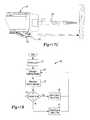
- FIG. 1is a perspective view of an exemplary power screwdriver.
- FIG. 2is a longitudinal section view of the power screwdriver of FIG. 1 .
- FIG. 3is a perspective view of the power screwdriver of FIG. 1 with the handle being disposed in a pistol-grip position.
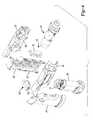
- FIG. 4is an exploded perspective view of the power screwdriver of FIG. 1 .
- FIGS. 5A-5Care fragmentary section views depicting different ways of actuating the trigger assembly of the power screwdriver of FIG. 1 .
- FIGS. 6A-6Care perspective views of exemplary embodiments of the trigger assembly.
- FIG. 7is a schematic for an exemplary implementation of the power screwdriver.
- FIGS. 8A-8Care flow charts for exemplary control schemes for the power screwdriver.
- FIG. 8Dis a flow chart for another embodiment of a control scheme for the power screwdriver.
- FIGS. 9A-9Eare charts illustrating different control curves that may be employed by the power screwdriver.
- FIG. 10is a diagram depicting an exemplary pulsing scheme for providing haptic feedback to the tool operator.
- FIG. 11is a flow chart depicting an automated method for calibrating a gyroscope residing in the power screwdriver.
- FIG. 12is a partial sectional view of the power screwdriver of FIG. 1 illustrating the interface between the first and second housing portions.
- FIG. 13A-13Care perspective views illustrating an exemplary lock bar assembly used in the power screwdriver.
- FIG. 14A-14Care partial sectional views illustrating the operation of the lock bar assembly during configuration of the screwdriver from the “pistol” arrangement to the “inline” arrangement.
- FIG. 15is a flowchart of an exemplary method for preventing an oscillatory state in the power screwdriver.
- FIG. 16is a fragmentary section view depicting an alternative trigger switch assembly.
- FIGS. 17A-17Care cross-sectional views illustrating alternative on/off and sensing mechanisms.
- FIG. 18is a flowchart for another exemplary control scheme for the tool.
- FIGS. 19A-19Bare diagrams illustrating an exemplary self-locking planetary gear set.
- FIG. 20is a perspective view of a second exemplary power screwd river.
- FIG. 21is a perspective view of a third exemplary power screwdriver.
- FIGS. 22A-Bare cross-sectional views of the exemplary power screwdriver of FIG. 21 , illustrating one way to activate the reaming tool.
- FIGS. 23A-Bare cross-sectional views of the exemplary power screwdriver of FIG. 21 , illustrating a second way to activate the reaming tool.
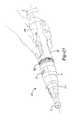
- FIG. 24is a perspective view of another exemplary power screwdriver and reaming tool.
- FIG. 25Ais a side view of the power screwdriver and reaming tool of FIG. 24 .
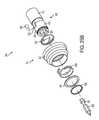
- FIG. 25Bis an exploded view of a portion of the power screwdriver and reaming tool of FIG. 24 .
- FIG. 25Cis a partial cross-sectional view of a portion of the power screwdriver and reaming tool of FIG. 24 .
- FIGS. 26A and 26Bare side views of the power screwdriver and reaming tool of FIG. 24 in operation.
- FIG. 27is a perspective view of another embodiment of a screwdriver and reaming accessory for a power tool.
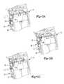
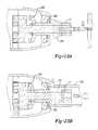
- FIG. 28Ais a perspective view of another embodiment of an exemplary power tool with improved user input control configured as a power wrench.
- FIG. 28Bis a top view of the power tool of FIG. 28A .
- FIG. 29is a schematic diagram of a control circuit for the power tool of FIGS. 28A and 28B .
- FIG. 30Adepicts a first exemplary control scheme for the power tool of FIGS. 28A-29 .
- FIG. 30Bdepicts a second exemplary control scheme for the power tool of FIGS. 28A-29 .
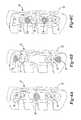
- FIGS. 31A-31Cdepict an exemplary actuator for selecting the direction of operation for the power tool of FIGS. 28A-29 .
- FIG. 32Ais a perspective view of another embodiment of an exemplary power tool with improved user input control configured as an alternative embodiment of a power wrench
- FIG. 32Bis a top view of the alternative embodiment of the power socket wrench of FIG. 31A .
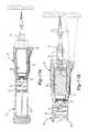
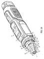
- FIG. 33is a perspective view of another embodiment of an exemplary power tool with improved user input control configured as an impact driver.
- FIGS. 34-36are side views partially in section of the impact driver of FIG. 33 .
- an exemplary power screwdriveris indicated generally by reference number 10 .
- the screwdriver 10is comprised generally of an output member 11 configured to rotate about a longitudinal axis 8 and a motor 26 driveably connected to the output member 11 to impart rotary motions thereto.
- Tool operationis controlled by a trigger switch, a rotational rate sensor and a controller in a manner further described below.
- a chuck or some other type of tool holdermay be affixed to the end of the output member 11 . Further details regarding an exemplary bit holder are set forth in U.S. patent application Ser. No. 12/394,426 which is incorporated herein by reference. Other components needed to construct the screwdriver 10 are further described below.
- the housing assembly for the screwdriver 10is preferably further comprised of a first housing portion 12 and a second housing portion 14 .
- the first housing portion 12defines a handle for the tool and can be mounted to the second housing portion 14 .
- the first housing portion 12is rotatable in relation to the second housing portion 14 .
- the first and second housing portions 12 , 14are aligned with each other along the longitudinal axis of the tool as shown in FIG. 1 This arrangement is referred to herein as an “inline” configuration.
- the screwdriver 10may be further configured into a “pistol-type” arrangement as shown in FIG. 3 .
- This second arrangementis achieved by depressing a rotation release mechanism 130 located in the side of the second housing portion 14 .
- the first housing portion 12will rotate 180 degrees in relation to the second housing portion 14 , thereby resulting in the “pistol-type” arrangement.
- the first and second housing portions 12 , 14form a concave elongated groove 6 that extends from one side of the tool continuously around the back to the other side of the tool.
- the first housing portion 12can be formed from a pair of housing shells 41 , 42 that can cooperate to define an internal cavity 43 .
- the internal cavity 43is configured to receive a rechargeable battery pack 44 comprised of one or more battery cells.
- a circuit board 45 for interfacing the battery terminals with other componentsis fixedly mounted in the internal cavity 43 of the first housing portion 12 .
- the trigger switch assembly 50is also pivotably coupled to the first housing portion 12 .
- the second housing portion 14can be formed of a pair of housing shells 46 , 47 that can cooperate to define another internal cavity 48 .
- the second housing portion 14is configured to receive the powertrain assembly 49 which includes the motor 26 , the transmission, and the output member 11 .
- the power train assembly 49can be mounted in the internal cavity 48 such that a rotational axis of the output member is disposed concentrically about the longitudinal axis of the second housing portion 14 .
- One or more circuit boards 45are also fixedly mounted in the internal cavity 48 of the second housing portion 14 (as shown in FIG. 14A ). Components mounted to the circuit board may include the rotational rate sensor 22 , the microcontroller 24 as well as other circuitry for operating the tool.
- the second housing portion 14is further configured to support the rotation release mechanism 130 .
- the rotary release mechanism 130can be mounted in either the first or second housing portions 12 , 14 .
- the release mechanism 130comprises a lock bar assembly 140 that engages with a set of locking features 132 associated with the other one of the first and second housing portions.
- the lock bar assembly 140is slidably mounted inside the second housing portion 14 .
- the lock bar assembly 140is positioned preferably so that it may be actuated by the thumb of a hand gripping the first housing portion 12 of the tool. Other placements of the lock bar assembly and/or other types of lock bar assemblies are also contemplated. Further details regarding another lock bar assembly is found in U.S. patent application Ser. No. 12/783,850 which was filed on May 20, 2010 and is incorporated herein by reference.
- the lock bar assembly 140is comprised of a lock bar 142 and a biasing system 150 .
- the lock bar 142is further defined as a bar body 144 , two push members 148 and a pair of stop members 146 .
- the push members 148are integrally formed on each end of the bar body 144 .
- the bar body 144can be an elongated structure having a pocket 149 into which the biasing system 150 is received.
- the pocket 149can be tailored to the particular configuration of the biasing system.
- the biasing system 150is comprised of two pins 152 and a spring 154 . Each pin 152 is inserted into opposing ends of the spring 154 and includes an integral collar that serves to retain the pin in the pocket. When placed into the pocket, the other end of each pin protrudes through an aperture formed in an end of the bar body with the collar positioned between the inner wall of the pocket and the spring.
- the stop members 146are disposed on opposite sides of the bar body 144 and integrally formed with the bar body 144 .
- the stop members 146can be further defined as annular segments that extend outwardly from a bottom surface of the bar body 144 .
- the stop members 146are arranged to engage the set of locking features 132 that are integrally formed on the shell assembly of the first housing portion 12 as best seen in FIG. 14A .
- the biasing system 150operates to bias the lock bar assembly 140 into the locking position. In this locking position, the engagement of the stop members 146 with the locking features 132 prevents the first housing portion from being rotated in relation to the second housing portion.
- the push members 148protrude through a push member aperture formed on each side of the second housing portion 14 .
- the stop members 146slide out of engagement with the locking features 132 as shown in FIG. 14B , thereby enabling the first housing portion to rotate freely in relation to the second housing portion.
- the push members 148are offset from the center axis on which the first housing portion 12 and the second housing portion 14 rotate with respect to one another. This arrangement creates an inertial moment that helps to rotate the second housing portion 14 in relation to the first housing portion 12 . With a single actuating force, the tool operator can release the lock bar assembly 140 and continue rotating the second housing portion.
- the usercan then continue to rotate the second housing portion.
- the usercan then continue to rotate the second housing portion (e.g., 180 degrees) until the stop members re-engage the locking features.
- the biasing system 150biases the lock bar assembly 140 into a locking position as shown in FIG. 14C .
- tool rotationis used to control rotation of the output member.
- rotational motion of the tool about the longitudinal axis of the output memberis monitored using the rotational motion sensor disposed in the power tool.
- the angular velocity, angular displacement, and/or direction of rotationcan be measured and used as a basis for driving the output member.
- the resulting configurationimproves upon the shortcomings of conventional input schemes.
- the control input and the resulting outputoccur as a rotation about the axis. This results in a highly intuitive control similar to the use of a manual screwdriver.
- control inputcould be rotational about a different axis associated with the tool.
- control inputcould be about an axis offset but in parallel with the axis of the output member or even an axis askew from the axis of the output member. Further details regarding the control scheme may be found in U.S. Patent Application No. 61/292,966 which was filed on Jan. 7, 2010, and is incorporated herein by reference.
- the switchmay be a single pole, single throw switch accessible on the exterior of the tool.
- the switchWhen the operator places the switch in an ON position, the tool is powered up (i.e., battery is connected to the controller and other electronic components). Rotational motion is detected and acted upon only when the tool is powered up.
- the switchWhen the operator places the switch in an OFF position, the tool is powered down and no longer operational.
- the tool operatoractuates a trigger switch assembly 50 to initiate tool operation.
- the trigger switch assembly 50is comprised primarily of an elongated casing 52 that houses at least one momentary switch 53 and a biasing member 54 , such as a spring.
- the elongated casing 52is movably coupled to the first housing portion 12 in such a way that allows it to translate and/or pivot about any point of contact by the operator. For example, if the tool operator presses near the top or bottom of the elongated casing 52 , the trigger switch assembly 50 pivots as shown in FIGS. 5A and 5B , respectively.
- the trigger switch assembly 50is translated inward towards the tool body as shown in FIG. 5C .
- the force applied to the elongated casing 52 by the operatorwill depress at least one of the switches from an OFF position to an ON position.
- the switches 53are arranged electrically in parallel with each other (as shown in FIG. 7 ) such that only one of the switches needs to be actuated to power up the tool.
- the biasing member 54biases the elongated casing 52 away from the tool, thereby returning each of the switches to an OFF position.
- the trigger switch assembly 50may be comprised of more than two switches 53 and/or more than one biasing member 54 as shown in FIGS. 6A-6C .
- FIG. 16illustrates an alternative trigger switch assembly 50 , where like numerals refer to like parts.
- Elongated casing 52is preferably captured by the first housing portion 12 so that it can only slide in one particular direction A.
- Elongated casing 52may have ramps 52 R.
- Ramps 52 Rengage cams 55 R on a sliding link 55 .
- Sliding link 55is captured by the first housing portion 12 so that it can preferably only slide in along a direction B substantially perpendicular to direction A.
- Sliding link 55is preferably rotatably attached to rotating link 56 .
- Rotating link 56may be rotatably attached to the first housing portion 12 via a post 56 P.
- elongated casing 52contacts springs 54 which bias elongated casing 52 in a direction opposite to direction A.
- sliding link 55may contact springs 55 S which bias sliding link 55 in a direction opposite to direction B.
- rotating link 56may contact a spring 56 S that biases rotating link 56 away from momentary switch 53 .
- switch 53can be disposed away from elongated casing 52
- motor 26can be provided adjacent to elongated casing 52 and sliding link 55 , allowing for a more compact arrangement.
- FIGS. 17A-17Billustrate one such an alternative switch assembly, where like numerals refer to like parts.
- a power train assembly 49 as shown in FIG. 4which includes motor 26 , the output member 11 and/or any transmission there between, is preferably encased in a housing 71 and made to translate axially inside the first housing portion 12 .
- a spring 72 of adequate stiffnessbiases the drivetrain assembly 71 forward in the tool housing.
- a momentary push-button switch 73is placed in axial alignment with the drivetrain assembly 71 .
- the drivetrain assemblyremains stationary but a collar 74 surrounding the bit is made to translate axially and actuate a switch. Other arrangements for actuating the switch are also contemplated.
- the battery 28is connected via power-regulating circuits to the rotational motion sensor, the controller 24 , and other support electronics.
- the controller 24immediately turns on a bypass switch 34 (e.g., FET). This enables the tool electronics to continue receiving power even after the pushbutton is released.
- the spring 72again biases the drivetrain assembly 71 forward and the pushbutton 73 is released.
- the controller 24will remain powered for a predetermined amount of time (e.g., 10 seconds) after the pushbutton 73 is released.
- the toolmay be applied to the same or different fastener without the tool being powered down.
- the controller 24will turn off the bypass switch 34 and power down the tool. It is preferable that there is some delay between a desired tool shut down and powering down the electronics. This gives the driver circuit time to brake the motor to avoid motor coasting.
- actuation of pushbutton 73also serves to reset (i.e., set to zero) the angular position. Powering the electronics may be controlled by the pushbutton or with a separate switch. Batteries which are replaceable and/or rechargeable serve as the power source in this embodiment, although the concepts disclosed herein as also applicable to corded tools.
- the operational state of the toolmay be conveyed to the tool operator by a light emitting diode 35 (LED) that will be illuminated while the tool is powered-up.
- the LED 35may be used to indicate other tool conditions. For example, a blinking LED 35 may indicate when a current level has been exceeded or when the battery is low. In an alternative arrangement, LED 35 may be used to illuminate a work surface.
- multiple LEDsmay be used to indicate the direction and speed of tool operation.
- three side-by-side LEDs 35can be lit consecutively one at a time from left to right when the output member 11 is rotating in a clockwise direction and from right to left when output member 11 is rotating in a counterclockwise direction.
- the duration of illumination, or blink ratemay indicate the speed of operation, where the longer each LED is lit, the slower the operation speed.
- the LEDs 35should to reflect this transition.
- the LEDs 35could all be lit simultaneously for a brief period when the tool's rotation passes back through the starting or reference point to indicate the change.
- the LEDs 35might turn off or return to showing battery life or some other status. If the user continues to rotate the tool in the opposite direction, the LEDs 35 would resume consecutive illumination and blink rate based on direction and speed of rotation.
- Other alternative embodimentscould include more or fewer LEDs used as described above.
- the direction of rotation of output member 11might be indicated by one LED arrow.
- the arrowmay change color based on speed, for example, from green to yellow to orange to red. The speed could also be indicated by the arrow's blink rate.
- the toolmay be powered up but not engaged with a fastener.
- the controllermay be further configured to drive the output member only when the pushbutton switch 73 is actuated.
- the output memberis driven only when the tool is engaged with a fastener and a sufficient bias force is applied to the drivetrain assembly.
- Control algorithmmay allow for a lesser bias force when a fastener is being removed.
- the output membermay be driven in a reverse direction when a sufficient bias load is applied to the drivetrain assembly as described above. Once the output member begins rotating, it will not shut off (regardless of the bias force) until some forward rotation is detected.
- Non-contacting sensing methodsmay also be used to control operation of the tool.
- a non-contact sensor 170may be disposed on the forward facing surface 174 of the tool adjacent to the bit 178 as shown in FIG. 17C .
- the non-contact sensor 170may be used to sense when the tool is approaching, being applied to, or withdrawing from a workpiece.
- Optic or acoustic sensorsare two exemplary types of non-contact sensors.
- an inertial sensorsuch as an accelerometer, can be configured to sense the relative position or acceleration of the tool.
- an inertial sensorcan detect linear motion of the tool towards or away from a workpiece along the longitudinal axis of the tool. This type of motion is indicative of engaging a workpiece with the tool or removing the tool after the task is finished.
- one sensing methodmay be used for startup while another is used for shutdown. Methods that respond to force applied to the workpiece may be preferred for determining when to start up the tool, while methods that sense the state of the fastener or movement of the tool away from the application may be preferred for determining when to modify tool output (e.g., shut down the tool).
- Components residing in the housing of the screwdriver 10include a rotational rate sensor 22 , which may be spatially separated in a radial direction from the output member as well as a controller 24 electrically connected to the rotational rate sensor 22 and a motor 26 as further illustrated schematically in FIG. 7 .
- a motor drive circuit 25enables voltage from the battery to be applied across the motor in either direction.
- the motor 26in turn drivably connects through a transmission (not shown) to the output member 11 .
- the motor drive circuit 25is an H-bridge circuit arrangement although other arrangements are contemplated.
- the screwdriver 10may also include a temperature sensor 31 , a current sensor 32 , a tachometer 33 and/or a LED 35 . Although a few primary components of the screwdriver 10 are discussed herein, it is readily understood that other components may be needed to construct the screwdriver.
- rotational motion sensor 22is further defined as a gyroscope.
- the operating principle of the gyroscopeis based on the Coriolis effect.
- the rotational rate sensoris comprised of a resonating mass.
- the resonating massWhen the power tool is subject to rotational motion about the axis of the spindle, the resonating mass will be laterally displaced in accordance with the Coriolis effect, such that the lateral displacement is directly proportional to the angular rate. It is noteworthy that the resonating motion of the mass and the lateral movement of the mass occur in a plane which is oriented perpendicular to the rotational axis of the rotary member.
- Capacitive sensing elementsare then used to detect the lateral displacement and generate an applicable signal indicative of the lateral displacement.
- Exemplary rotational rate sensorsinclude the ADXRS150 or ADSRS300 gyroscope devices commercially available from Analog Devices, or the ISZ-650 or IXZ-2500 gyroscope devices commercially available from InvenSense, Inc. It is readily understood that accelerometers, compasses, inertial sensors and other types of rotational motion sensors are contemplated by this disclosure. It is also envisioned that the sensor as well as other tool components may be incorporated into a battery pack or any other removable pieces that interface with the tool housing.
- the rotational motion sensor 22monitors rotational motion of the sensor with respect to the longitudinal axis of the output member 11 .
- a control module implemented by the controller 24receives input from the rotational motion sensor 22 and drives the motor 26 and thus the output member 11 based upon input from the rotational motion sensor 22 .
- the control modulemay drive the output member 11 in the same direction as the detected rotational motion of the tool.
- modulemay refer to, be part of, or include an Application Specific Integrated Circuit (ASIC); an electronic circuit; a combinational logic circuit; a field programmable gate array (FPGA); a processor (shared, dedicated, or group) that executes code; other suitable components that provide the described functionality; or a combination of some or all of the above, such as in a system-on-chip.
- ASICApplication Specific Integrated Circuit
- FPGAfield programmable gate array
- modulemay include memory (shared, dedicated, or group) that stores code executed by the processor, where code, as used above, may include software, firmware, and/or microcode, and may refer to programs, routines, functions, classes, and/or objects.
- angular displacementmay be monitored by the controller 24 based upon input received from the rotational motion sensor 22 .
- a starting or reference point ( ⁇ )is initialized to zero. Any subsequent angular displacement of the tool is then measured in relation to this reference.
- the control schemeis implemented as computer executable instructions residing in a memory and executed by a processor of the controller 24 .
- the usermay wish to reset the starting or reference point ( ⁇ ).
- the user's wristmay be rotated 40° clockwise, and the user wants to reverse the direction of the tool's operation. Instead of rotating back through the reference point and continuing to rotate to the left, the user may reset the reference point to be the current position (in this example, 40° clockwise). Any subsequent counterclockwise rotation from the new reference point will reverse the direction of the rotation of output member 11 .
- the second exemplary embodimentwhere holding in the trigger switch assembly 50 is how the tool remains in a powered-up state, releasing the trigger switch assembly 50 would reset the reference point.
- pressing the dedicated zero button 210would reset the reference point.
- Persons skilled in the artwill recognize that other implementations can be envisioned, such as requiring the zero button 210 to be pressed and held for a short period of time in order to prevent accidental zeroing.
- Angular displacement of the toolis then monitored at step 82 .
- the angular displacementis derived from the rate of angular displacement over time or angular velocity ( ⁇ TOOL ) as provided by the gyroscope.
- ⁇ TOOLangular velocity
- the rotational rate sensor described aboveis presently preferred for determining angular displacement of the tool, it is readily understood that this disclosure is not limited to this type of sensor. On the contrary, angular displacement may be derived in other manners and/or from other types of sensors.
- the signal from any rotational rate sensorcan be filtered in the analog domain with discrete electrical components and/or digitally with software filters.
- the motoris driven at different rotational speeds depending upon the amount of rotation. For example, the angular displacement is compared at 84 to an upper threshold. When the angular displacement exceeds an upper threshold ⁇ UT (e.g., 30° of rotation), then the motor is driven at full speed as indicated at 85 . The angular displacement is also compared at 86 to a lower threshold. When the angular displacement is less than the upper threshold but exceeds a lower threshold ⁇ LT (e.g., 5° of rotation), then the motor is driven at half speed as indicated at 87 . It is readily understood that the control scheme may employ more or less displacement thresholds as well as drive the motor at other speeds.
- ⁇ UTe.g. 30° of rotation
- Angular displacementcontinues to be monitored at step 82 . Subsequent control decisions are based on the absolute angular displacement in relation to the starting point as shown at 83 .
- the operating speed of the motoris maintained. In this way, continuous operation of the tool is maintained until the tool is returned to its original position.
- returning the tool to its original positionmeans that the user returns the tool to within 10° to 15° of the original position, for example. This creates a range around the reference point that allows for a small margin of user error. The user is not required to find the exact reference point that was set.
- the output of the toolis modified at 190 .
- the voltage applied to the motoris discontinued at 190 , thereby terminating operation of the tool.
- the speed at which the motor is drivenis reduced to some minimal level that allows for spindle rotation at no load.
- Threshold valuesmay include hysteresis; that is, the lower threshold is set at one value (e.g. six degrees) for turning on the motor but set at a different value (e.g., four degrees) for turning off the motor, for example. It is also to be understood that only the relevant steps of the methodology are discussed in relation to FIG. 8A , but that other functionality may be needed to control and manage the overall operation of the system.
- FIG. 8BA variant of this control scheme 80 ′ is shown in FIG. 8B .
- the motor speedmay be set generally as a function of the angular displacement as indicated at 87 ′. More specifically, the motor speed may be set proportional to the full speed. In this example, the motor speed is derived from a linear function. It is also noted that more complex functions, such as quadratic, exponential or logarithmic functions, may be used to control motor speed. In another embodiment, the motor speed could be proportional to the displacement, velocity, acceleration, or a combination thereof (as shown in FIG. 8B , step 87 ′).
- direction of tool rotationmay be used to control the rotational direction of the output member.
- a clockwise rotation of the toolresults in a clockwise rotation of the output member
- a counterclockwise rotation of the toolresults in a counterclockwise rotation of the output member.
- the toolmay be configured with a switch that enables the operator to select the rotational direction of the output member.
- rotational motion sensor 22can be used in diverse ways.
- the motion sensor 22can be used to detect fault conditions and terminate operation.
- One such schemeis shown in FIG. 8C where, if the angular displacement is larger than the upper threshold ⁇ U (step 86 ), it could be advantageous to check whether the angular displacement exceeds on a second upper threshold ⁇ OT (step 88 ). If such threshold is exceeded, then operation of screwdriver 10 can be terminated (step 89 ).
- Such arrangementis important in tools that should not be inverted or put in certain orientations. Examples of such tools include table saws, power mowers, etc.
- operation of screwdriver 10can be terminated if motion sensor 22 detects a sudden acceleration, such as when a tool is dropped.
- control schemes in FIGS. 8A-8Ccan be modified by monitoring angular velocity of output member 11 about the longitudinal axis 8 instead of angular displacement.
- an upper thresholdsuch as 100°/second
- a lower thresholdsuch as 50°/second
- control schemes shown in FIGS. 8A-8Ccan be modified by monitoring angular acceleration instead of angular velocity.
- an upper thresholdsuch as 100°/second per second
- a lower thresholdsuch as 50°/second per second
- a combination of displacement, velocity, and/or accelerationcould determine the control scheme.
- a ratcheting control scheme 60is also contemplated by this disclosure.
- the controllermonitors angular displacement of the tool at 61 based upon input received from the rotational motion sensor 22 . From angular displacement, the controller is able to determine the direction of the displacement at 62 and drive the motor 26 to simulate a ratchet function as further described below.
- the controllermust also receive an indication from the operator at 63 as to which direction the operator desires to ratchet.
- the screwdriver 10may be configured with a switch that enables the operator to select between forward and reverse ratchet directions.
- Other input mechanismsare also contemplated.
- the controllerdrives the motor in the following manner.
- the output memberis driven at a higher ratio than the rotation experienced by the tool.
- the output membermay be driven one or more full revolutions for each quarter turn of the tool by the operator.
- the output memberis rotated at a ratio greater than one when the direction of rotational motion is the same as a user selected ratcheting direction as indicated at 65 . It may not be necessary for the user to select a ratchet direction. Rather the control may make a ratcheting direction decision based on a parameter, for example, an initial rotation direction is assumed the desired forward direction.
- the output memberis driven at a one-to-one ratio.
- the output memberis rotated at a ratio equal to one when the direction rotational motion is the opposite the user selected ratcheting direction as indicated at 67 .
- the bit and screwwould remain stationary as the user twists the tool backward to prepare for the next forward turn, thereby mimicking a ratcheting function.
- FIG. 9illustrates three exemplary control curves.
- Curve Ais a linear control curve in which there is a large variable control region. If the user does not need fine control for the application and simply wants to run an application as fast as possible, the user would prefer curve B. In this curve, the tool output ramps up and obtains full output quickly. If the user is running a delicate application, such as seating a brass screw, the user would prefer curve C. In this curve, obtaining immediate power is sacrificed to give the user a larger control region. In the first part of the curve, output power changes slowly; whereas, the output power changes more quickly in the second part of the curve.
- the toolmay be programmed with two or more control curves.
- the tool operatormay select one of a set number of control curves directly with an input switch.
- the controllerapplies the control curve indicated by the input switch until the tool operator selects a different control curve.
- the controller of the toolcan select an applicable control curve based on an input control variable (ICV) and its derivative.
- ICVsinclude displacement, velocity, and acceleration.
- the motor speed from the selected curvemay be determined by either the same or some other variable.
- the controllermay select the control curve based on distance a trigger has traveled and the speed at which the user actuates the trigger switch. In this example, the selection of the control curve is not made until the trigger has traveled some predetermined distance (e.g., 5% of the travel range as shown in FIG. 9A ) as measured from a starting position.
- the controllercomputes the speed of the trigger and selects a control curve from a group of control curves based on the computed speed. If the user simply wants to drive the motor as quick as possible, the user will tend to pull the trigger quickly. For this reason, if the speed of trigger exceeds some upper speed threshold, the controller infers that the user wants to run the motor as fast as possible and selects an applicable control curve (e.g., Curve B in FIG. 9A ). If the user is working on a delicate application and requires more control, the user will tend to pull the trigger more slowly.
- an applicable control curvee.g., Curve B in FIG. 9A
- the controllerinfers the user desires more control and selects a different control curve (e.g., Curve C in FIG. 9A ). If the speed of the trigger falls between the upper and lower thresholds, the controller may select another control curve (e.g., Curve A in FIG. 9A ). Curve selection could be (but is not limited to being) performed with every new trigger pull, so the user can punch the trigger to run the screw down, release, and obtain fine seating control with the next slower trigger pull.
- Curve selectioncould be (but is not limited to being) performed with every new trigger pull, so the user can punch the trigger to run the screw down, release, and obtain fine seating control with the next slower trigger pull.
- the controllerthen controls the motor speed in accordance with the selected control curve.
- the distance travelled by the triggercorrelates to a percent output power. Based on the trigger distance, the controller will drive the motor at the corresponding percent output in accordance with the selected control curve. It is noted that this output could be motor pulse width modulation, as in an open loop motor control system, or it could be motor speed directly, as in a closed loop motor control system.
- the controllermay select the control curve based on a different input control variable, such as the angular distance the tool has been rotated from a starting point and its derivative, i.e., the angular velocity at which the tool is being rotated. Similar to trigger speed, the controller can infer that the user wants to run the motor as fast as possible when the tool is rotated quickly and infer that the user wants to run the motor slower when the tool is being rotated slowly. Thus, the controller can select and apply a control curve in the manner set forth above. In this example, the percentage of the input control variable is computed in relation to a predefined range of expected rotation (e.g., +/ ⁇ 180 degrees). Selecting an applicable control curve based on another type of input control variable land its derivative is also contemplated by this disclosure.
- a different input control variablesuch as the angular distance the tool has been rotated from a starting point and its derivative, i.e., the angular velocity at which the tool is being rotated. Similar to trigger speed, the controller can infer that the
- the controllermay compute trigger speed and select a suitable control curve after the trigger has been released or otherwise begins traveling towards its starting position.
- FIG. 9Billustrates three exemplary control curves that can be employed during such a back-off condition.
- Curve Dis a typical back off curve which mimics the typical ramp up curve, such as Curve A. In this curve, the user passes through the full range of analog control before returning to trigger starting position.
- Curve Eis an alternative curve for faster shutoff. If the trigger is released quickly, the controller infers that the user simply wants to shut the tool off and allows the user to bypass most of the variable speed region.
- the controllerinfers that the user desires to enter the variable speed region. In this case, the controller may select and apply Curve F to allow the user better finish control, as would be needed to seat a screw. It is envisioned that the controller may monitor the input control variable and select an applicable control curve based on other types of triggering events which occur during tool operation.
- Ramp up curvesmay be combined with back off curves to form a single selectable curve as shown in FIG. 9C .
- the userwishes to use the tool to drive a long machine screw and thus selects the applicable control curves using the input switch as discussed above.
- the controllerapplies Curve B to obtain full tool output quickly.
- the controllerapplies Curve F, thereby giving the user more control and the ability to seat the screw to the desired tightness.
- Selection of control curvesmay be based on the input control variable in combination with other tool parameters.
- the controllermay monitor output torque using known techniques such as sensing current draw. With reference to FIG. 9D , the controller has sensed a slow trigger release, thereby indicating the user desires variable speed for finish control. If the controller further senses that output torque is high, the controller can infer that the user needs more output power to keep the fastener moving (e.g., a wood screw application). In this case, the controller selects Curve G, where the control region is shifted upward to obtain a usable torque. On the other hand, if the controller senses that output torque is low, the controller can infer that additional output power is not needed (e.g., a machine screw application) and thus select Curve H. Likewise, the controller may select from amongst different control curves at tool startup based on the sensed torque. Tool parameters other than torque may also be used to select a suitable control curve.
- Selection of control curvescan also be based on a second derivative of the input control variable.
- the controllercan continually compute the acceleration of the trigger. When the acceleration exceeds some threshold, the controller may select a different control curve. This approach is especially useful if the tool has already determined a ramp up or back off curve but the user desires to change behavior mid curve. For example, the user has pulled the trigger slowly to allow a screw to gain engagement with a thread. Once engaged, the user punches the trigger to obtain full output. Since the tool always monitors trigger acceleration, the tool senses that the user is finished with variable speed control and quickly sends the tool into full output as shown in FIG. 9E .
- trigger inputis used as an example in this scenario, but it should be noted that any user input control, such as a gesture, could be used as the input control variable.
- sensor 22can detect when the user shakes a tool to toggle between control curves or even operation modes.
- a usercan shake a sander to toggle between a rotary mode and a random orbit mode.
- the controllercontrols the motor speed in accordance with the same input control variable as is used to select the control curve. It is envisioned that the controller may control the motor speed with an input control variable that differs from the input control variable used to select the control curve.
- motor speedmay be set based on displacement of the trigger; whereas, the control curve is selected in accordance with the velocity at which the trigger is actuated.
- the screwdriver 10includes a current sensor 32 to detect current being delivered to the motor 26 . It is disadvantageous for the motor of the tool to run at high current levels for a prolonged period of time. High current levels are typically indicative of high torque output. When the sensed current exceeds some predefined threshold, the controller is configured to modify tool output (e.g., shut down the tool) to prevent damage and signal to the operator that manually applied rotation may be required to continue advancing the fastener and complete the task.
- the toolmay be further equipped with a spindle lock. In this scenario, the operator may actuate the spindle lock, thereby locking the spindle in fixed relation to the tool housing. This causes the tool to function like a manual screwdriver.
- the current sensor and controllermay control the motor so that, at high torque levels, the power tool can be used as a simulated manual, ratcheting screwdriver.
- the controllermonitors a current sense signal (I SENSE ) from the current sensor, where I SENSE indicates the amount of current being delivered to the motor.
- the controllercompares I SENSE to a predetermined reference value I MAX , which indicates the maximum current that may be delivered to the motor.
- I MAXcan be stored in memory and can be a fixed value or a user-selectable value. In many applications I SENSE and I MAX may correlate or be related to the output torque of the drive shaft. At step 806 , if I SENSE does not exceed I MAX , then the controller continues to operate the power tool according to one of the control schemes set forth in FIGS. 8A-8C .
- step 808if I SENSE exceeds I MAX for a predetermined amount of time, then the controller causes a reduced, but non-zero, amount of power (LOW-PWM) to be delivered to the motor in the direction that the motor and output shaft were previously being driven.
- LOW-PWMis low enough so that the LOW-PWM signal cannot overcome the output torque being encountered by the tool shaft.
- I SENSEindicates that the current being delivered to the motor is greater than approximately 20 amps (e.g., approximately 25 amps) for at least 200 ms
- the controlleroperates to deliver a LOW-PWM signal to the motor that is less than approximately 20% (e.g., approximately 15%) of the maximum PWM duty cycle that was previously being delivered to the motor during normal operation. Therefore, if the user continues to rotate the tool housing in the driving direction of the motor, the user will need to manually apply a torque that is greater than the output torque, so that the tool functions as a manual screwdriver.
- the control scheme of FIG. 8Dis not limited for use with the inertia control schemes of FIGS. 8A-8C , but can also be used with a more traditional electric power tool or screwdriver that is operated by a switch or trigger.
- the screwdriver 10may be further configured to provide a user-perceptible output when the tool is operational. Providing the user with haptic feedback is one example of a user-perceptible output.
- the motor driven circuit 25may be configured as an H-bridge circuit as noted above and in FIG. 7 .
- the H-bridge circuitis used to selectively open and close pairs of field effect transistors (FETs) to change the current flow direction and therefore the rotational direction of the motor.
- the motorBy quickly transitioning back and forth between forward and reverse, the motor can be used to generate a vibration perceptible to the tool operator.
- the frequency of a vibrationis dictated by the time span for one period and the magnitude of a vibration is dictated by the ratio of on time to off time as shown in FIG. 10 .
- Other schemes for vibrating the toolalso fall within the broader aspects of this disclosure.
- the H-bridge circuit 25(as seen in FIG. 7 ) may be driven in the manner described above before the angular displacement of the tool reaches the lower threshold. Consequently, the user is provided with haptic feedback when the spindle is not rotating. It is also envisioned that user may be provided haptic feedback while the spindle is rotating. For example, the positive and negative voltage may be applied to the motor with an imbalance between the voltages such that the motor will advance in either a forward or reverse direction while still vibrating the tool. It is understood that haptic feedback is merely one example of a perceptible output and other types of outputs also are contemplated by this disclosure.
- Vibrations having differing frequencies and/or differing magnitudescan also be used to communicate different operational states to the user.
- the magnitude of the pulsescan be changed proportionally to speed to help convey where in a variable-speed range the tool is operating. So as not to limit the total tool power, this type of feedback may be dropped out beyond some variable speed limit (e.g., 70% of maximum speed).
- the vibrationsmay be used to warn the operator of a hazardous tool condition.
- the haptic feedbackcan be coupled with other perceptible indicators to help communicate the state of the tool to the operator. For instance, a light on the tool may be illuminated concurrently with the haptic feedback to indicate a particular state.
- haptic feedbackcan be used to indicate that the output member has rotated 360°, or that a particular desired torque setting has been achieved.
- an automated methodfor calibrating a gyroscope residing in the screwdriver 10 .
- Vsensesensed-analog voltage
- FIG. 11illustrates an exemplary method for calibrating the offset error of the gyroscope in the tool.
- the methodis implemented by computer-executable instructions executed by a processor of the controller 24 in the tool.
- the calibration proceduremust occur when the tool is stationary. This is likely to occur once an operation is complete and/or the tool is being powered down. Upon completing an operation, the tool will remain powered on for a predetermined amount of time. During this time period, the calibration procedure is preferably executed. It is understood that the calibration procedure may be executed at other times when the tool is or is likely to be stationary. For example, the first derivative of the sensed voltage measure may be analyzed to determine when the tool is stationary.
- the calibration procedurebegins with a measure of the offset error as indicated at 114 .
- the offset erroris measured, it is compared to a running average of preceding offset error measurements (ZROavg).
- the running averagemay be initially set to the current calibration value for the offset error.
- the measured offset erroris compared at 115 to a predefined error threshold. If the absolute difference between the measured offset error and the running average is less than or equal to the predefined offset error threshold, the measured offset error may be used to compute a newly-calibrated offset error. More specifically, the measurement counter (calCount) may be incremented at 116 and the measured offset error is added to an accumulator (ZROaccum) at 117 .
- the running averageis then computed at 118 by dividing the accumulator by the counter.
- a running averageis one exemplary way to compute the newly-calibrated offset error.
- the running averagecan be stored in memory at 121 as the newly-calibrated offset error and subsequently used by the controller during the calculations of the rotational rate.
- the toolWhen the absolute difference between the measured offset error and the running average exceeds the predefined offset error threshold, the tool must be rotating. In this case, the accumulator and measurement counter are reset as indicated at steps 126 and 127 . The calibration procedure may continue to execute until the tool is powered down or some other trigger ends the procedure.
- the toolmay employ a longer-term calibration scheme.
- the method set forth abovedetermines whether or not there is a need to alter the calibration value.
- the longer-term calibration schemewould use a small amount of time (e.g., 0.25 s) to perform short-term calibrations, since errors would not be critical if no rotational motion is sensed in the time period.
- the averaged ZROwould be compared to the current calibration value. If the averaged ZRO is greater than the current calibration value, the controller would raise the current calibration value. If the averaged ZRO is less than the current calibration value, the controller would lower the current calibration value. This adjustment could either be incremental or proportional to the difference between the averaged value and the current value.
- While a tool body's uncontrolled spinningmay not have a large effect on tool operation for trigger-controlled tools, it may have a prominent and detrimental effect for rotation-controlled tools. If the user controls tool output speed through the tool-body rotation, any undesired motion of the tool body could cause an undesired output speed. In the following scenario, it can even create an oscillation effect.
- the userrotates the tool clockwise in an attempt to drive a screw. If there is a great amount of backlash, the motor speed will increase rapidly until the backlash is taken up. If the user's grip is too relaxed at this point, the tool will spin uncontrolled in the counterclockwise direction. If the tool passes the zero rotation point and enters into negative rotation, the motor will reverse direction and spin counterclockwise. The backlash will again be taken up, eventually causing the tool body to spin uncontrolled in the clockwise direction. This oscillation or oscillatory state may continue until tool operation ceases.
- FIG. 15depicts an exemplary method of preventing such an oscillatory state in the screwdriver 10 .
- the methodworks cooperatively with the control scheme described in relation to FIG. 8A . It is understood that the method can be adapted to work with other control schemes, including those set forth above.
- the methodis implemented by controller 24 in the tool.
- Rotational direction of the output spindleis dictated by the angular displacement of the tool as discussed above. For example, a clockwise rotation of the tool results in clockwise rotation of the output member. However, the onset of an oscillatory state may be indicated when tool rotation occurs for less than a predetermined amount of time before being rotated in the opposing direction. Therefore, upon detecting rotation of the tool, a time is initiated at 102 . The timer accrues the amount of time the output member has been rotating in a given direction. Rotational motion of the tool and its direction are continually being monitored as indicated at 103 .
- the methodcompares the value of the timer to a predefined threshold (e.g., 50 ms) at 104 . If the value of the timer is less than the threshold, the onset of an oscillatory state may be occurring. In an exemplary embodiment, the oscillatory state is confirmed by detecting two oscillations although it may be presumed after a single oscillation. Thus, a flag is set at 105 to indicate the occurrence of a first oscillation. If the value of the timer exceeds the threshold, the change in rotational direction is presumed to be intended by the operator and thus the tool is not in an oscillating state. In either case, the timer value is reset and monitoring continues.
- a predefined thresholde.g. 50 ms
- a corrective actionmay be initiated as indicated at 107 .
- the toolmay be shut down for a short period of time (e.g., 1 ⁇ 4 second), thereby enabling the user to regain control of the tool before operation is resumed.
- a short period of timee.g. 1 ⁇ 4 second
- Other types of corrective actionsare also contemplated by this disclosure. It is envisioned that the corrective action may be initiated after a single oscillation or some other specific number of oscillations exceeding two. Likewise, other techniques for detecting an oscillatory state fall within the broader aspects of this disclosure.
- the toolmay be configured with self-locking planetary gear set 90 disposed between the output member 11 and a drive shaft 91 of the motor 26 .
- the self-locking gear setcould include any planetary gear set which limits the ability to drive the sun gear through the ring gear and/or limits the ability of the spindle to reverse. This limiting feature could be inherent in the planetary gear set or it could be some added feature such as a sprag clutch or a one way clutch.
- one inherent method to limit the ability of a ring gear to back drive a sun gear 92is to add an additional ring gear 93 as the output of the planetary gear set 94 and fix the first ring gear 95 . By fixing the first ring gear 95 , power is transferred through the sun gear 92 into the planetary gear set 94 into the second (unfixed, out) ring gear 93 .
- the advantage of having a self-locking planetary gear setis that when the motor is bogged down at high torque levels during twisting operations such as, but not limited to, threaded fasteners, the tool operator can overcome the torque by twisting the tool. This extra torque applied to the application from the tool operator is counteracted by the forces within the self-locking planetary gear set, and the motor does not back drive. This allows the tool operator to apply additional torque to the application.
- the controllerwhen the sensed current exceeds some predefined threshold, the controller may be configured to drive the motor at some minimal level that allows for spindle rotation at no load. This avoids stressing the electronics in a stall condition but would allow for ratcheting at stall. The self-locking planetary gears would still allow the user to override stall torque manually. Conversely, when the user turns the tool in the reverse direction to wind up for the next forward turn, the spindle rotation would advance the bit locked in the screwhead, thereby counteracting the user's reverse tool rotation.
- a second exemplary power screwdriveris indicated generally by reference number 10 ′.
- This embodimentallows the user to hold the screwdriver 10 ′ in the palm of the user's hand and actuate the trigger switch assembly 50 ′ with the palm of the user's hand, most preferably the area of the palm that forms the base of the user's thumb.
- the tool operatoractuates the trigger switch assembly 50 ′ to initiate tool operation.
- the trigger switch assembly 50 ′Given the orientation of the screwdriver 10 ′ in the palm of the user's hand, it should be recognized that the trigger switch assembly 50 ′ is actuated and remains depressed just by holding the screwdriver 10 ′. This allows for natural and intuitive use, where the user can simply hold the screwdriver 10 ′ and turn it.
- the trigger switch assembly 50 ′is substantially similar to the trigger switch assembly 50 .
- the trigger switch assembly 50 ′is comprised primarily of an elongated casing 52 that houses at least one momentary switch 53 and a biasing member 54 , such as a spring.
- the elongated casing 52is movably coupled to housing 200 in such a way that allows it to translate and/or pivot about any point of contact by the operator. For example, if the tool operator presses near the top or bottom of the elongated casing 52 , the trigger switch assembly 50 ′ pivots as shown in FIGS. 5A and 5B , respectively.
- the trigger switch assembly 50 ′is translated inward towards the tool body as shown in FIG. 5C .
- the force applied to the elongated casing 52 by the operatorwill depress at least one of the switches from an OFF position to an ON position.
- the switches 53are arranged electrically in parallel with each other (as shown in FIG. 7 ) such that only one of the switches needs to be actuated to power up the tool.
- the biasing member 54biases the elongated casing 52 away from the tool, thereby returning each of the switches to an OFF position.
- the trigger switch assembly 50 ′may be comprised of more than two switches 53 and/or more than one biasing member 54 as shown in FIGS. 6A-6 .C. This embodiment otherwise functions as described for the previous embodiment.
- a third exemplary power screwdriveris indicated generally by reference number 10 ′′.
- the tool operatoractuates the trigger switch assembly 50 ′′ with the user's index finger to power up the screwdriver 10 ′′.
- the trigger switch assembly 50 ′′functions as an ON/OFF switch. Once the user presses and releases the trigger switch assembly 50 ′′, the screwdriver 10 ′′ is in an ON state (i.e., the battery is connected to the controller and other electronic components). Rotational motion is detected and acted upon only when the tool is powered up. When the operator places the switch in an OFF position, the tool is powered down and is no longer operational.
- the screwdriver 10 ′′remains in the ON state until the user turns it off by pressing and releasing the trigger switch assembly 50 ′′ again. It is also contemplated that the screwdriver 10 ′′ will automatically shut off after a period of inactivity, and the trigger switch assembly 50 ′′ may be implemented in other ways.
- Output member 11rotates around longitudinal axis 8 ′ based on angular displacement as described above. In other words, the user rotates the screwdriver 10 ′′ to drive output member 11 .
- a zero button 210allows the user to reset the starting or reference point as previously described.
- the toolmay be further configured with a reaming tool 214 disposed between the second housing portion 14 and the output member 11 .
- a usermay wish to refine a hole drilled using the tool or remove burrs from the cut end of a piece of conduit.
- This embodimenthas two modes of operation: the motor 26 either drives the output member 11 or the reaming tool 214 .
- the modeis selected manually by the user as shown in FIGS. 22A-22B and described below.
- the modeis selected by applying either the output member 11 or the reaming tool 214 to a workpiece in order to use screwdriver 10 ′′ as a screwdriver or a reamer, respectively, as shown in FIGS. 23A-23B and described below.
- Other means for selecting the mode of operationare also contemplated by this disclosure.
- the reaming toolwould oscillate. For example, the user's wrist remains rotated clockwise, and the reaming tool rotates in a clockwise direction for a short time period, reverses direction for a short time period, repeating until operation is terminated.
- the reaming toolwould have a pulse mode. If the drive signal is pulsed, a spike in the torque output might facilitate overcoming a burr.
- the power toolcould have multiple gears associated with it. At lower speeds, higher torque could be achieved while at higher speeds, lower torque would be sufficient for driving screws, for example.
- FIGS. 22A-22Bshow an exemplary clutch mechanism for selectively engaging the reaming tool 214 (to operate screwdriver 10 ′′ as a reamer) or the output member 11 (to operate screwdriver 10 ′′ as a screwdriver). It is to be understood that the representation of the reaming tool 214 in FIGS. 22A-22B has been simplified from its depiction in FIG. 21 in order to more clearly convey the mode switching.
- the userrotates a collar 240 between two positions to select the mode of operation. It should be understood that this collar could also be implemented to translate between the two positions while remaining rotationally fixed.
- the collar 240is attached to a grounding ring 228 .
- the grounding ring 228engages a planet carrier 236 and prevents it from rotating.
- the motordrives the planets 237 to rotate about the pins of the planet carrier 236 , causing the ring gear 232 to rotate. This drives the reaming tool 214 while the output member 11 remains fixed, and as such, screwdriver 10 ′′ operates as in reamer mode.
- the planet carrier 236When the grounding ring 228 is in the forward position as shown in FIG. 22B , the planet carrier 236 is free to rotate, and the ring gear 232 is fixed. In this configuration, the motor drives the planets 237 which in turn drives the output member 11 , and as such, screwdriver 10 ′′ operates in screwdriver mode. It is envisioned that in an alternative embodiment, the ring gear 232 and the planet carrier 236 may be fixed to one another and free to rotate at the same time.
- FIGS. 23A and 23Billustrate another exemplary clutch mechanism for selecting the mode of operation.
- a dog type clutch 238is used to selectively engage the reaming tool 214 . It is to be understood that the representation of the reaming tool 214 in FIGS. 23A-23B has been simplified from its depiction in FIG. 21 in order to more clearly convey the mode switching.
- screwdriver 10 ′′operates as a screwdriver as shown in FIG. 23A unless the user applies the reaming tool 214 to a workpiece 230 . If no force is applied to the reaming tool, the dog clutch 238 is not engaged, and the output member 11 is free to rotate.
- the userapplies the reaming tool 214 to a workpiece 230 .
- This bias loadapplies a force to the compression springs 234 , as shown in FIG. 23B .
- This engages the dog clutch 238which causes the reaming tool 214 to rotate with the output member 11 .
- This embodimentotherwise functions the same as the other embodiments discussed above.
- a reaming attachment 300may be coupled to an output shaft 312 of a power tool 310 .
- the power tool 310may be similar to the above-described screwdriver 10 that is driven according to rotation of the tool housing as sensed by a rotational motion sensor.
- the power tool 310may be an ordinary power drill, power driver, or power screwdriver that is driven according to actuation of an on-off power switch or a variable speed trigger switch.
- the reaming attachment 300includes a driving shaft 302 integral with the output shaft 312 for rotation with the output shaft 312 about a longitudinal axis X.
- the driving shaft 302is permanently attached to the output shaft 312 of the power tool 310 .
- a similar reaming attachment 300 ′may include a driving shaft 302 ′ having a hex fitting 303 ′ that can be removably coupled to an output shaft of a power tool, e.g., by a quick-release tool holder, a chuck, or a hex tool holder.
- a driving shaftcan be removably coupled to an output shaft, e.g., by a threaded connection, a friction fit coupling, a snap-fit connector, and/or a bayonet connection.
- the driving shaft 302non-rotationally carries a screwdriving portion 320 and a reaming portion 330 .
- the screwdriving portion 320 and the reaming portion 330always rotate together with the driving shaft 302 about the axis X, and thus together with the output shaft 312 of the power tool 310 .
- the reaming portion 330includes a front body portion 332 and a rear body portion 340 that are non-rotationally carried by the driving shaft 302 .
- the front body portion 332has a stepped configuration with a plurality of cylindrical steps 334 that increase in diameter from front to rear. Adjacent cylindrical steps 334 are connected by frustroconical surfaces 336 .
- the rear body portion 340comprises a generally cylindrical disc 342 .
- the rear body portion 340is axially fixed to the driving shaft 302 and abuts the housing front end of the power tool 310 .
- the front body portion 332is axially moveable relative to the driving shaft 302 and is biased away from the rear body portion 340 by a compression spring 344 disposed between the front body portion 332 and the rear body portion 340 .
- the front and rear body portions 332 , 340have radial slots 346 , 348 , respectively, that extend in an axial direction. Removably received in the axial slots 346 , 348 is a reaming blade 350 .
- the blade 350has a rear end 352 axially fixed to the rear body portion 340 , and a working end 354 that remains stationary relative to the driving shaft 302 when the front body portion 340 moves axially.
- the working end 354has a stepped configuration with a plurality of hook shaped cutting surfaces 356 , each having a diameter corresponding to one of the cylindrical steps 334 on the front body portion 332 .
- the output shaft 312causes the driving shaft 302 , screwdriving portion 320 , and the front and rear bodies 332 , 340 of the reaming portion 340 to rotate simultaneously about the longitudinal axis X.
- the reaming attachment 320may be used to drive a fastener 360 into a workpiece W (as shown in FIG. 25 ).
- a screwdriving bit 362is inserted into the bit holding portion 322 .
- the front body 332remains biased in its forward-most position, so that the cutting surfaces 356 of the blade 350 are not exposed.
- the driving shaft 302causes the screwdriving bit 362 to rotate to drive the screw 360 into the workpiece.
- the reaming attachment 230may also be used to ream the edge 370 of a pipe P to remove burrs or shavings.
- the front bodyis inserted into the pipe P until one of the stepped cylindrical surfaces 334 or conical surfaces 336 abut against the edge 370 of the pipe P.
- the front body 332retracts rearward in a direction R against the force of spring 344 . This retraction of the front body 332 causes the cutting surfaces 356 of the blade 350 to be exposed.
- One of the hook shaped cutting surfaces 356hooks around the edge 370 of the blade.
- the cutting surface 356rotates to remove material from the edge 370 of the pipe P.
- the front portion 332is removed from the pipe P and moves axially forward opposite the direction R, to cause apparent retraction of the cutting surfaces 356 .
- the screwdriving portion 320includes a bit holding portion 322 formed at the front end of the driving shaft 302 .
- the bit holding portion 322is formed with an internal bore 324 configured to retain a bit 362 , such a screwdriving bit, for driving a fastener (e.g., screw 360 ) into a workpiece W.
- the bit holding portion 322may include a bit retention assembly for holding the bit 362 in the internal bore 324 .
- a bit retention assembly 380includes a shaft 412 having a sidewall 413 defining the internal bore 324 in the form of a polygonal (e.g., hexagonal) cavity.
- the stepped front body 332 of the reamer portion 340functions as an actuator sleeve and is disposed around a first end 424 of the shaft 412 .
- the stepped front body 332engages a retainer 426 (e.g., a ball) that is received in a groove opening 428 of the sidewall 413 of the shaft 412 .
- a retainer 426e.g., a ball
- inside wall of the stepped front body 332includes an internal ramp portion 432 and an internal cylindrical portion 433 that each can selectively abut the retainer ball 426 .
- a retainer spring 430substantially surrounds the shaft 412 and biases the retainer ball 426 in a forward direction (best shown in FIG. 25C ).
- the retainer spring 430can be a helical compression spring having a helix portion 430 a and ending at a bend portion that transitions to an inwardly projecting portion that is received at least partially in the groove opening 428 to bias the retainer 426 in a forward direction toward the front end 424 of the shaft 412 .
- a rearward portion of the retainer spring 430is disposed against a forward facing shoulder 412 a of the shaft 412 .
- An actuator spring 436biases the stepped front body 332 in a rearward direction relative to the first end 424 of the shaft 412 .
- a retainer clip 440is received in a recessed groove 442 in the first end 424 of the shaft 412 for supporting a washer 444 against a forward end of the actuator spring 436 .
- a second end of the actuator spring 436is received against an interior shoulder portion 445 of the stepped front body 332 in order to bias the stepped front body 332 in a rearward direction relative to the first end 424 of the shaft 412 .
- the stepped front body 332In its rest position, the stepped front body 332 is positioned over the bit holding portion 322 so that the inner cylindrical portion 433 abuts the ball 426 and biases the ball radially inwardly.
- the end of the bit 362engages the ball 426 , pushing the ball 426 rearward against the force of the retainer spring 430 .
- the ball 426moves rearward in the groove opening 428 , it also moves radially outward along the internal ramp 432 , providing clearance for further insertion of the bit.
- the spring 430causes the ball 426 to move forward and radially inward to engage a notch or groove 363 in the bit 362 .
- the inner cylindrical surface 433now pushes the ball 462 radially inward to retain the bit 362 in the bore 324 .
- the stepped front body 332is pulled in a forward direction against the force of the spring 436 .
- Thiscauses the ramp 432 to be axially aligned with the ball 452 so that the ball can move radially outward along the surface of the ramp.
- the ballno longer tightly engages the groove 363 in the bit, enabling the bit 362 to be removed from the bore 324 .
- the bit retention device 380may include a plunger for ejecting the bit from the bore when the ball is not engaging the bit.
- other types of bit retention mechanismsmay be used, such as, for example, a hog ring, a retention clip, or a magnet. Examples of other retention mechanisms can be found, e.g., in U.S. Patent App. Pub. No. 2012/0326401, which is incorporated by reference.
- the driving shaft 302may be formed with a screwdriving or nut driving head portion, or another type of rotational driving implement.
- a rotary power tool in the form of a ratchet wrench 510may include the above or below described embodiments of an improved user input control. Exemplary components and features of the ratchet wrench 510 are described below.
- ratchet wrench 510While the following description is provided with reference to a ratchet wrench 510 , it should be readily understood to one of ordinary skill in the art that the broader aspects of the present disclosure are applicable to other types of power tools that have an output axis at an angle to a rotatable axis of the motor, including but not limited to other power tools that have an elongated housing aligned perpendicularly to a rotational axis of an output member of the tool, e.g., a right angle drill or right angle screwdriver.
- the ratchet wrench 510is a right angle socket wrench and includes an elongated housing 512 having a longitudinal axis 509 .
- the housing 512may be formed from two or more housing shells that cooperate to define an internal cavity.
- the housing 512is configured to receive a motor 526 , a transmission 515 coupled to an output of the motor 526 , and an intermediate rotatable shaft 519 rotatably coupled to an output of the transmission 515 .
- Coupled to the housing 512is a ratcheting head 521 having a ratcheting mechanism 523 coupled to an output of the intermediate shaft 519 , and an output member or drive shaft 511 , where the rotational axis 508 of the output member 511 is arranged generally perpendicular to the longitudinal axis 509 of the housing 512 .
- the drive shaft 511is configured to rotate about its rotational axis 508 in a ratcheting manner in one direction (either clockwise or counterclockwise) when the intermediate shaft 519 is rotated by the motor in either a clockwise or a counterclockwise direction.
- the ratcheting head 521further includes a mechanical switch 525 that enables the rotational direction of the output shaft 511 to be switched between ratcheting in the clockwise direction and ratcheting in the counterclockwise direction, regardless of the direction of rotation of the intermediate shaft. Further details regarding operation of the ratcheting head can be found in prior art ratcheting wrenches, including, e.g., U.S. Pat. Nos.
- the ratcheting headmay have other types of transmission mechanisms that do not ratchet, but that only change the direction of rotation by a right angle, right angle or bevel gears, as will be understood by one of ordinary skill in the art.
- the output member 511may has a polygonal shape (e.g., a square) for being received in a corresponding polygonal opening in a socket wrench accessory.
- a chuck or another type of tool holdermay be affixed to the end of the output member 511 . Further details regarding an exemplar/bit holder are set forth in U.S. patent application Ser. No. 12/394,426 which is incorporated herein by reference.
- the housing 512may also receive or be coupled to a rechargeable and/or removable power source 528 such as a battery pack with one or more battery cells.
- the power sourcemay be an AC power plug coupled to the housing.
- An on-off switch 553may be coupled to the housing 512 and may control power-up of the tool as discussed below.
- a control circuit 530may be disposed on one or more circuit boards inside of the housing and in electrical communication with the switch 553 and the power source 528 . As shown schematically in FIG. 29 , the control circuit 530 includes a rotational rate sensor 522 and a microcontroller 524 as well as other circuitry for interfacing with the power source 528 , the on-off switch 553 , and the motor 526 and for operating the tool.
- the control circuit 530may operate according to one of the control methods discussed above with respect to the other embodiments of power tools, or according to one of the alternative control methods discussed below.
- the rotational rate sensor 522may be spatially separated in a radial direction from the rotational axis of the output member 511 and may be oriented so that it senses rotational movement about the axis 508 of the output member 511 .
- a motor drive circuit 525enables voltage from the power source 528 to be applied across the motor 526 in either direction.
- the motor drive circuit 525comprises an H-bridge circuit arrangement although other arrangements are contemplated.
- the control circuit 530 of the wrench 510may also include a temperature sensor 531 , a current sensor 532 , a tachometer 533 and/or a LED 535 .
- the controller 524may be coupled to a direction switch module 540 that can be actuated by the user to indicate a desired direction of rotation of the output shaft.
- the rotational motion sensor 522is gyroscope, such as a MEMS gyroscope.
- the operating principle of the gyroscopeis based on the Coriolis effect.
- the rotational rate sensormay be comprised of one or more resonating masses. When the power tool is subject to rotational motion about the axis of the output member, the resonating mass will be laterally displaced in accordance with the Coriolis effect, such that the lateral displacement is directly proportional to the angular rate.
- Sensing elements in the gyroscopedetect the lateral displacement of the mass(es) and generate an applicable signal indicative of the lateral displacement.
- An exemplary rotational rate sensoris the ADXRS150 or ADXRS300 gyroscope device commercially available from Analog Devices, or the ISZ-650 or IXZ-2500 gyroscope devices commercially available from InvenSense, Inc.
- rotational rate sensor 522described above is presently preferred for determining angular displacement of the tool, it is readily understood that this disclosure is not limited to this type of sensor. On the contrary, angular displacement may be derived in other manners and/or from other types of sensors. It is also noted that the signal from any rotational rate sensor can be filtered in the analog domain with discrete electrical components and/or digitally with software filters. It is readily understood that accelerometers, compasses, inertial sensors and other types of rotational motion sensors are contemplated by this disclosure. It is also envisioned that the rotational sensor as well as other tool components may be incorporated into a battery pack or any other removable pieces that interface with the tool housing.
- the rotational motion sensor 522senses and monitors rotational motion of the housing 512 with respect to the rotational axis 508 of the output member 511 .
- a control module implemented by the controller 524receives input from the rotational motion sensor 522 and drives the motor 526 and thus the output member 511 based upon input from the rotational motion sensor 522 .
- the term modulemay refer to, be part of, or include an Application Specific Integrated Circuit (ASIC); an electronic circuit; a combinational logic circuit; a field programmable gate array (FPGA); a processor (shared, dedicated, or group) that executes code; other suitable components that provide the described functionality; or a combination of some or all of the above, such as in a system-on-chip.
- the term modulemay include memory (shared, dedicated, or group) that stores code executed by the processor, where code, as used above, may include software, firmware, and/or microcode, and may refer to programs, routines, functions, classes, and/or objects.
- the control circuit 530 and its control methodoperate such that user rotation of the housing about the rotational axis 508 of the output shaft 511 is used to control motor operation.
- rotational motion of the tool about the rotational axis 508 of the output member 511is monitored using the rotational motion sensor 522 .
- the angular velocity, angular displacement, and/or direction of rotationcan be sensed and used as a basis for driving the motor 526 and thus the output shaft 511 .
- the control input and the resulting outputoccur as rotation about the same axis. This results in a highly intuitive control similar to the use of a manual wrench.
- the control schemeis implemented as computer executable instructions residing in a memory and executed by a processor of the controller 524 .
- the switch 553may be include a pushbutton switch accessible on the exterior of the tool housing.
- the switch 513When the operator depresses the pushbutton switch 513 a first time, the tool is powered up (i.e., battery is connected to the controller and other electronic components). Rotational motion is detected and acted upon only when the tool is powered up.
- the on/off switch 513may be a single pole, single throw switch accessible on the exterior of the tool. When the operator places the switch in an ON position, the tool is powered up. When the operator places the switch in an OFF position, the tool is powered down and no longer operational.
- FIG. 30AOne exemplary power control scheme 540 for the tool 510 is illustrated in FIG. 30A .
- a starting or reference point ( ⁇ )is initialized to zero. Any subsequent angular displacement of the tool is then measured in relation to this reference.
- angular displacement ( ⁇ ) of the toolis monitored. The angular displacement may be derived from the rate of angular displacement over time or angular velocity as provided by the rotational rate sensor 522 .
- the reference value ( ⁇ )is set to be the previous reference value plus the change in angular displacement ( ⁇ ).
- the controllerdetermines whether the new reference value indicates that the tool has been rotated in the clockwise direction.
- the controllerdrives the motor to rotate. If not, then at step 546 , the controller determines whether the new reference value indicates that the tool has been rotated in the counterclockwise direction. If so, then at step 545 , the controller drives the motor to rotate. Whenever the motor rotates, regardless of the direction of rotation of the housing, the output shaft 511 will rotate in the direction set by the switch 525 .
- Threshold valuesmay include hysteresis; that is, the lower threshold is set at six degrees for turning on the motor but set at four degrees for turning off the motor, for example. It is also to be understood that only the relevant steps of the methodology are discussed above in relation to FIG. 30A , but that other functionality may be needed to control and manage the overall operation of the wrench.
- FIG. 30BAnother exemplary power control scheme 640 for the tool 510 is illustrated in FIG. 30B .
- the power toolis configured so that the motor only rotates when the housing 512 is rotated in the same direction as the switch 525 has been set for rotating the output shaft 511 .
- the motorwill only rotate if the housing 512 is also rotated in the clockwise direction by about the output shaft axis 508 . If the housing 512 is rotated in the counterclockwise direction, then the motor will not rotate.
- the motorwill only rotate if the housing is also rotated in the counterclockwise direction about the output shaft axis 508 . If the housing 512 is rotated in the clockwise direction, then the motor will not rotate.
- FIGS. 31A-31Cillustrate an exemplary direction switch module 550 that is coupled to the direction control switch 525 for this purpose.
- the direction control switch 525is a knob that can be moved among three positions: left, center and right.
- the knobis coupled directly to a slide bar 552 having a toothed portion 554 .
- the tooth of the slid barengages a wheel 556 of a switching mechanism, rotating the wheel and thereby determining the rotational direction of the ratcheting mechanism.
- the switch 525is moved to the left position as shown in FIG.
- the direction of the ratcheting mechanismis set to counterclockwise.
- the switch 525is moved to the right position as shown in FIG. 310 , the direction of the ratcheting mechanism is set to clockwise.
- Further details regarding an exemplary switching mechanismare set forth in U.S. Pat. Nos. 3,529,498 and 3,621,738 which are incorporated herein by reference.
- the toothed portion 554 of the slide bar 552When positioned in either the left or right positions, the toothed portion 554 of the slide bar 552 also closes a set of electrical contacts, thereby communicating the position of the slide bar 552 to the controller 524 . This will enable the controller to drive the motor only when the tool housing is rotated in the direction set by the position of the actuator as will be further described below.
- the toothed portion 554electrically connects left electrical contact 556 and center electrical contact 558 to indicate to the controller that the user desires to operate the tool in only the counterclockwise direction.
- the slide bar 552When the slide bar 552 is in the right position, as shown in FIG.
- the toothed portion 554electrically connects a right electrical contact 560 and the center electrical contact 558 to indicate to the controller that the user desires to operate the tool only in the clockwise direction.
- the toothed portion 554does not electrically connect the center electrical contact 558 to either the left electrical contact 556 or the right electrical contact 560 , which indicates to the controller that the user does not desire to operate the tool.
- Other types of switches and sensors for switchescould be substituted, as will be apparent to one of ordinary skill in the art.
- a starting or reference point ( ⁇ )is initialized to zero. Any subsequent angular displacement of the tool is then measured in relation to this reference.
- angular displacement ( ⁇ ) of the toolis monitored. The angular displacement may be derived from the rate of angular displacement over time or angular velocity as provided by the rotational rate sensor 522 .
- the reference value ( ⁇ )is set to be the previous reference value plus the change in angular displacement ( ⁇ ).
- the controllerdetermines whether the new reference value indicates that the housing has been rotated in the clockwise direction about the axis 608 .
- the controllerdetermines whether the switch 525 is also set to rotate the output shaft in the clockwise direction. If so, then at step 545 , the controller drives the motor to rotate (the motor can be rotated in either direction). If not, then, at step 648 , the controller terminates operation of the motor.
- the controllerdetermines whether the new reference value indicates that the tool has been rotated in the counterclockwise direction. If so, then at step 649 , the controller determines whether the switch 525 is also set to rotate the output shaft in the counterclockwise direction. If so, then at step 645 , the controller drives the motor to rotate (in either direction). Whenever the motor rotates, regardless of the direction of rotation of the housing, the output shaft 511 will rotate in the direction set by the switch 525 .
- Subsequent control decisionsare based on the absolute angular displacement in relation to the starting point as shown at 643 .
- the angular displacement of the toolremains above the applicable threshold, then the operating speed of the motor is maintained. In this way, continuous operation of the tool is maintained until the tool is returned to its original position.
- Threshold valuesmay include hysteresis; that is, the lower threshold is set at six degrees for turning on the motor but set at four degrees for turning off the motor, for example. It is also to be understood that only the relevant steps of the methodology are discussed above in relation to FIG. 30B , but that other functionality may be needed to control and manage the overall operation of the wrench.
- the motormay be driven at a variable speed having some relationship to the amount or rate of rotation of the housing 512 about the axis 508 , as described above with respect to the other embodiments.
- the control schemes of FIGS. 30A and 30Bmay incorporate the haptic feedback algorithms discussed above to indicate to the user when the tool is active and ready for use.
- the control schemes of FIGS. 30A and 30Bmay be used with in-line ratcheting screwdrivers or other in-line tools where the output axis is coincident or parallel to the axis of the motor and/or the housing or handle.
- FIGS. 32A and 32Billustrate an alternative embodiment of a power socket wrench 510 ′.
- the wrench 510 ′is similar to the wrench 510 described above except that the wrench 510 ′ is equipped with two drive squares 515 ′, 516 ′, one extending from each side of a ratchet head 517 ′.
- the drive squaresare configured to receive a socket as is readily known in the art.
- the motor and the output shaftonly need to be driven in one direction regardless of the direction of rotation of the housing because one of the drive squares 515 ′ can be used for clockwise ratcheting rotation, while the other of the drive squares 516 ′ can be used for counterclockwise ratcheting rotation.
- the userselects the appropriate side of the ratchet head to apply to the workpiece.
- the wrench 510 ′may be programmed to operate according to the control scheme of FIG. 30A , described above. That is, the tool operator actuates an on/off switch 513 ′ in order to power up the tool and begin work.
- the userrotates the tool housing about the rotational axis of the drive squares. Angular displacement of the tool housing is monitored in relation to a zero position. The motor is driven once the angular displacement exceeds a minimum displacement threshold and continues until the tool housing is rotated back to the zero position. It is understood that the motor is driven in a fixed direction which is independent of the direction the tool housing is rotated.
- the impact driver 760is comprised generally of a housing 762 having a shape like a conventional power drill.
- the housing 762defines a handle portion 763 which is gripped by a user during tool operation.
- An output member 764 that includes a tool bit holderextends from one end of the housing and is configured to rotate about its rotational axis 765 .
- the rotational axis of the output member 764may be angled relative to a longitudinal axis of the handle portion 763 (e.g., substantially perpendicular).
- a motor 766 residing in the housing 762is drivably connected to the output member 764 to impart rotary motion thereto.
- An impact mechanism 767is interposed between the motor 766 and the output member 764 .
- Further details regarding an exemplary impact mechanismare set forth in U.S. Pat. No. 5,016,501 and U.S. Patent Application Pub. Nos. 2007/0267207 and 2010/0071923, which are incorporated herein by reference.
- Other exemplary impact mechanismscan be found in IDS600 Impact Screwdriver and FDS600 Impact Screwdriver commercially available from Black & Decker and in the DCF895 Impact Driver, DCF896 Impact Driver, and the DCF880 Impact Wrench available commercially from DeWALT Industrial Tool Co.
- the impact driver 760includes a printed circuit board 770 to which is mounted a microcontroller, rotational motion sensor (e.g., a gyroscope) and other control electronics, similar to the components of the control circuit of FIG. 7 , described above.
- the printed circuit board 770has a front end portion 776 and a rear end portion 772 .
- the front end portion 776is sandwiched between a pair of elastomeric dampers 782 (or springs), one of which is coupled to an exterior wall 778 of the housing 762 , and the other of which is coupled to a fixed interior wall 780 of the housing 762 .
- the dampers 782are oriented to dampen vibrations in a direction Y that is substantially perpendicular to the longitudinal axis L of the motor and output shaft.
- the rear end portion 772 of the printed circuit board 770is fixedly connected to a floating shoe 774 that is not fixedly connected to the housing.
- a depending portion 784 of the shoe 774is coupled to a plurality of elastomeric dampers 786 (or springs) that abut the interior wall 780 of the housing and another portion of the housing.
- the dampers 786are oriented to dampen vibrations in a direction X that is substantially parallel to the longitudinal axis L.
- the dampers 782 and 786combine to dampen vibrations from the motor and the impact mechanism (which can generate large vibrations) so that the vibrations do not interfere with the readings of the rotary motion sensor.
- the tool operatoractuates an on/off switch 761 in order to power up the tool and begin work.
- the userrotates the tool housing 763 about the rotational axis of the output member 764 to drive the motor.
- Angular displacement of the tool housingis monitored in relation to a zero position.
- the motoris driven once the angular displacement exceeds a minimum displacement threshold and continues until the tool housing is rotated back to the zero position.
- the motoris driven is a clockwise direction.
- the motoris driven in a counter-clockwise direction.
- the rotational direction of the motoris determined by the rotational motion of the tool housing.
- the impact drivermay otherwise operate in a manner similar to one or more of the control schemes described above (e.g., with respect to FIGS. 8A-8C, 9A-9E, 18, 30A, and 30B .
- Example embodimentsare provided so that this disclosure will be thorough and will fully convey the scope to those who are skilled in the art. Numerous specific details are set forth such as examples of specific components, devices, and methods, to provide a thorough understanding of embodiments of the present disclosure. It will be apparent to those skilled in the art that specific details need not be employed, that example embodiments may be embodied in many different forms and that neither should be construed to limit the scope of the disclosure. In some example embodiments, well-known processes, well-known device structures, and well-known technologies are not described in detail.
Landscapes
- Engineering & Computer Science (AREA)
- Mechanical Engineering (AREA)
- Details Of Spanners, Wrenches, And Screw Drivers And Accessories (AREA)
Abstract
Description
This application is a continuation-in-part of U.S. patent application Ser. No. 13/773,696, filed on Feb. 22, 2013, (now U.S. Pat. No. 9,266,178, issued Feb. 23, 2016), which is a continuation-in-part of U.S. patent application Ser. No. 13/404,620, filed on Feb. 24, 2012, (now U.S. Pat. No. 8,418,778, issued Apr. 16, 2013), which application is a continuation-in-part of U.S. patent application Ser. No. 13/120,873 filed on May 13, 2011, (now U.S. Pat. No. 8,286,723, issued Oct. 16, 2012), which is a national phase of PCT/US2011/020511 filed Jan. 7, 2011. This application also claims the benefit of U.S. Provisional Application No. 61/746,606, filed on Dec. 28, 2012, to U.S. Provisional Application No. 61/292,966, filed on Jan. 7, 2010, and to U.S. Provisional Application No. 61/389,866, filed on Oct. 5, 2010. The entire disclosures of each of the above applications are incorporated herein by reference.
The present disclosure relates generally to power tools, such as a power screwdriver, and, more particularly, to a control scheme that controls rotation of an output member of a tool based on rotary user input.
In present-day power tools, users may control tool output through the use of an input switch. This can be in the form of a digital switch in which the user turns the tool on with full output by pressing a button and turns the tool off by releasing the button. More commonly, it is in the form of an analog trigger switch in which the power delivered to the tool's motor is a function of trigger travel. In both of these configurations, the user grips the tool and uses one or more fingers to actuate the switch. The user's finger must travel linearly along one axis to control a rotational motion about a different axis. This makes it difficult for the user to directly compare trigger travel to output rotation and to make quick speed adjustments for finer control.
Another issue with this control method is the difficulty in assessing joint tightness. As a joint becomes tighter, the fastener becomes more reluctant to move farther into the material. Because the tool motor attempts to continue spinning while the output member slows down, a reactionary torque can be felt in the user's wrist as the user increases bias force in an attempt to keep the power tool stationary. In this current arrangement, the user must first sense tightness with the wrist before making the appropriate control adjustment with the finger.
This section provides background information related to the present disclosure which is not necessarily prior art.
An improved method is provided for operating a power tool. The method includes: monitoring rotational motion of the power tool about an axis using a rotational motion sensor disposed in the power tool; determining a direction of the rotational motion about the axis; and driving the output member in a direction defined by the detected rotational motion of the tool, where the output member is driven by a motor residing in the power tool. This approach results in a highly intuitive method for operating the tool similar to the use of a manual screwdriver.
In one aspect of the disclosure, the improved operation methods are incorporated into a power tool. The power tool is comprised of: a housing; an output member at least partially contained in the housing and configured to rotate about a longitudinal axis; a motor contained in the housing and drivably connected to the output member to impart rotary motion thereto; a rotational motion sensor arranged in the housing at a location spatially separated from the output member and operable to detect rotational motion of the housing about the longitudinal axis of the output member; and a controller configured in the housing to receive a signal indicative of rotational motion from the rotational motion sensor. The controller determines a direction of the rotation motion of the housing about the axis and drives the motor in the same direction as the rotational motion of the housing.
In another aspect of the disclosure, the power tool may be further configured with a reamer tool.
This section provides a general summary of the disclosure, and is not a comprehensive disclosure of its full scope or all of its features. Further areas of applicability will become apparent from the description provided herein. The description and specific examples in this summary are intended for purposes of illustration only and are not intended to limit the scope of the present disclosure.
The drawings described herein are for illustrative purposes only of selected embodiments and not all possible implementations, and are not intended to limit the scope of the present disclosure. Corresponding reference numerals indicate corresponding parts throughout the several views of the drawings.
With reference toFIGS. 1 and 2 , an exemplary power screwdriver is indicated generally byreference number 10. Thescrewdriver 10 is comprised generally of anoutput member 11 configured to rotate about alongitudinal axis 8 and amotor 26 driveably connected to theoutput member 11 to impart rotary motions thereto. Tool operation is controlled by a trigger switch, a rotational rate sensor and a controller in a manner further described below. A chuck or some other type of tool holder may be affixed to the end of theoutput member 11. Further details regarding an exemplary bit holder are set forth in U.S. patent application Ser. No. 12/394,426 which is incorporated herein by reference. Other components needed to construct thescrewdriver 10 are further described below. While the following description is provided with reference toscrewdriver 10, it is readily understood that the broader aspects of the present disclosure are applicable to other types of power tools, including but not limited to tools having elongated housings aligned concentrically with the output member of the tool.
The housing assembly for thescrewdriver 10 is preferably further comprised of afirst housing portion 12 and asecond housing portion 14. Thefirst housing portion 12 defines a handle for the tool and can be mounted to thesecond housing portion 14. Thefirst housing portion 12 is rotatable in relation to thesecond housing portion 14. In a first arrangement, the first andsecond housing portions FIG. 1 This arrangement is referred to herein as an “inline” configuration.
Thescrewdriver 10 may be further configured into a “pistol-type” arrangement as shown inFIG. 3 . This second arrangement is achieved by depressing arotation release mechanism 130 located in the side of thesecond housing portion 14. Upon depressing therelease mechanism 130, thefirst housing portion 12 will rotate 180 degrees in relation to thesecond housing portion 14, thereby resulting in the “pistol-type” arrangement. In the second arrangement, the first andsecond housing portions longitudinal axis 8 allows the operator to better control the screwdriver.
With reference toFIGS. 2 and 4 , thefirst housing portion 12 can be formed from a pair ofhousing shells internal cavity 43. Theinternal cavity 43 is configured to receive arechargeable battery pack 44 comprised of one or more battery cells. Acircuit board 45 for interfacing the battery terminals with other components is fixedly mounted in theinternal cavity 43 of thefirst housing portion 12. Thetrigger switch assembly 50 is also pivotably coupled to thefirst housing portion 12.
Likewise, thesecond housing portion 14 can be formed of a pair ofhousing shells internal cavity 48. Thesecond housing portion 14 is configured to receive thepowertrain assembly 49 which includes themotor 26, the transmission, and theoutput member 11. Thepower train assembly 49 can be mounted in theinternal cavity 48 such that a rotational axis of the output member is disposed concentrically about the longitudinal axis of thesecond housing portion 14. One ormore circuit boards 45 are also fixedly mounted in theinternal cavity 48 of the second housing portion14 (as shown inFIG. 14A ). Components mounted to the circuit board may include therotational rate sensor 22, themicrocontroller 24 as well as other circuitry for operating the tool. Thesecond housing portion 14 is further configured to support therotation release mechanism 130.
With reference toFIGS. 3, 4, 12, 13, and 14 , therotary release mechanism 130 can be mounted in either the first orsecond housing portions release mechanism 130 comprises alock bar assembly 140 that engages with a set of locking features132 associated with the other one of the first and second housing portions. In the exemplary embodiment, thelock bar assembly 140 is slidably mounted inside thesecond housing portion 14. Thelock bar assembly 140 is positioned preferably so that it may be actuated by the thumb of a hand gripping thefirst housing portion 12 of the tool. Other placements of the lock bar assembly and/or other types of lock bar assemblies are also contemplated. Further details regarding another lock bar assembly is found in U.S. patent application Ser. No. 12/783,850 which was filed on May 20, 2010 and is incorporated herein by reference.
Thelock bar assembly 140 is comprised of alock bar 142 and abiasing system 150. Thelock bar 142 is further defined as abar body 144, twopush members 148 and a pair ofstop members 146. Thepush members 148 are integrally formed on each end of thebar body 144. Thebar body 144 can be an elongated structure having apocket 149 into which thebiasing system 150 is received. Thepocket 149 can be tailored to the particular configuration of the biasing system. In the exemplary embodiment, thebiasing system 150 is comprised of twopins 152 and aspring 154. Eachpin 152 is inserted into opposing ends of thespring 154 and includes an integral collar that serves to retain the pin in the pocket. When placed into the pocket, the other end of each pin protrudes through an aperture formed in an end of the bar body with the collar positioned between the inner wall of the pocket and the spring.
Thestop members 146 are disposed on opposite sides of thebar body 144 and integrally formed with thebar body 144. Thestop members 146 can be further defined as annular segments that extend outwardly from a bottom surface of thebar body 144. In a locking position, thestop members 146 are arranged to engage the set of locking features132 that are integrally formed on the shell assembly of thefirst housing portion 12 as best seen inFIG. 14A . Thebiasing system 150 operates to bias thelock bar assembly 140 into the locking position. In this locking position, the engagement of thestop members 146 with the locking features132 prevents the first housing portion from being rotated in relation to the second housing portion.
To actuate thelock bar assembly 140, thepush members 148 protrude through a push member aperture formed on each side of thesecond housing portion 14. When thelock bar assembly 140 is translated in either direction by the tool operator, thestop members 146 slide out of engagement with the locking features132 as shown inFIG. 14B , thereby enabling the first housing portion to rotate freely in relation to the second housing portion. Of note, thepush members 148 are offset from the center axis on which thefirst housing portion 12 and thesecond housing portion 14 rotate with respect to one another. This arrangement creates an inertial moment that helps to rotate thesecond housing portion 14 in relation to thefirst housing portion 12. With a single actuating force, the tool operator can release thelock bar assembly 140 and continue rotating the second housing portion. The user can then continue to rotate the second housing portion. The user can then continue to rotate the second housing portion (e.g., 180 degrees) until the stop members re-engage the locking features. Once thestop members 146 are aligned with the locking features, thebiasing system 150 biases thelock bar assembly 140 into a locking position as shown inFIG. 14C .
An improved user-input method for thescrewdriver 10 is proposed. Briefly, tool rotation is used to control rotation of the output member. In an exemplary embodiment rotational motion of the tool about the longitudinal axis of the output member is monitored using the rotational motion sensor disposed in the power tool. The angular velocity, angular displacement, and/or direction of rotation can be measured and used as a basis for driving the output member. The resulting configuration improves upon the shortcomings of conventional input schemes. With the proposed configuration, the control input and the resulting output occur as a rotation about the axis. This results in a highly intuitive control similar to the use of a manual screwdriver. While the following description describes rotation about the longitudinal axis of the output member, it is readily understood that the control input could be rotational about a different axis associated with the tool. For example, the control input could be about an axis offset but in parallel with the axis of the output member or even an axis askew from the axis of the output member. Further details regarding the control scheme may be found in U.S. Patent Application No. 61/292,966 which was filed on Jan. 7, 2010, and is incorporated herein by reference.
This type of control scheme requires the tool to know when the operator would like to perform work. One possible solution is a switch that the tool operator actuates to begin work. For example, the switch may be a single pole, single throw switch accessible on the exterior of the tool. When the operator places the switch in an ON position, the tool is powered up (i.e., battery is connected to the controller and other electronic components). Rotational motion is detected and acted upon only when the tool is powered up. When the operator places the switch in an OFF position, the tool is powered down and no longer operational.
In the exemplary embodiment, the tool operator actuates atrigger switch assembly 50 to initiate tool operation. With reference toFIGS. 5A-5C , thetrigger switch assembly 50 is comprised primarily of anelongated casing 52 that houses at least onemomentary switch 53 and a biasingmember 54, such as a spring. Theelongated casing 52 is movably coupled to thefirst housing portion 12 in such a way that allows it to translate and/or pivot about any point of contact by the operator. For example, if the tool operator presses near the top or bottom of theelongated casing 52, thetrigger switch assembly 50 pivots as shown inFIGS. 5A and 5B , respectively. If the tool operator presses near the middle of theelongated casing 52, thetrigger switch assembly 50 is translated inward towards the tool body as shown inFIG. 5C . In any case, the force applied to theelongated casing 52 by the operator will depress at least one of the switches from an OFF position to an ON position. If there are two ormore switches 53, theswitches 53 are arranged electrically in parallel with each other (as shown inFIG. 7 ) such that only one of the switches needs to be actuated to power up the tool. When the operator releases the trigger, the biasingmember 54 biases theelongated casing 52 away from the tool, thereby returning each of the switches to an OFF position. The elongated shape of the casing helps the operator to actuate the switch from different grip positions. It is envisioned that thetrigger switch assembly 50 may be comprised of more than twoswitches 53 and/or more than one biasingmember 54 as shown inFIGS. 6A-6C .
Slidinglink 55 is preferably rotatably attached torotating link 56. Rotatinglink 56 may be rotatably attached to thefirst housing portion 12 via apost 56P.
Accordingly, when the user moveselongated casing 52 along direction A, ramps52 R move cams 55R (and thus sliding link55) along direction B. This causesrotating link 56 to rotate and make contact withmomentary switch 53, powering up thescrewdriver 10.
Preferably, elongated casing52 contacts springs54 which bias elongatedcasing 52 in a direction opposite to direction A. Similarly, slidinglink 55 may contactsprings 55S which bias slidinglink 55 in a direction opposite to direction B. Also, rotatinglink 56 may contact a spring56S thatbiases rotating link 56 away frommomentary switch 53.
Persons skilled in the art will recognize that, becauseswitch 53 can be disposed away fromelongated casing 52,motor 26 can be provided adjacent toelongated casing 52 and slidinglink 55, allowing for a more compact arrangement.
Persons skilled in the art will also recognize that, instead of having the user activating adiscrete trigger assembly 50 in order to power upscrewdriver 10,screwdriver 10 can have an inherent switch assembly.FIGS. 17A-17B illustrate one such an alternative switch assembly, where like numerals refer to like parts.
Referring now toFIGS. 17A-17B for this embodiment, apower train assembly 49 as shown inFIG. 4 , which includesmotor 26, theoutput member 11 and/or any transmission there between, is preferably encased in ahousing 71 and made to translate axially inside thefirst housing portion 12. Aspring 72 of adequate stiffness biases thedrivetrain assembly 71 forward in the tool housing. A momentary push-button switch 73 is placed in axial alignment with thedrivetrain assembly 71. When the tool is applied to a fastener, a bias load is applied along the axis of the tool and thedrivetrain assembly 71 translates rearward compressing the spring and contacting the pushbutton. In an alternative example, the drivetrain assembly remains stationary but acollar 74 surrounding the bit is made to translate axially and actuate a switch. Other arrangements for actuating the switch are also contemplated.
When thepushbutton 73 is actuated (i.e., placed in a closed state), thebattery 28 is connected via power-regulating circuits to the rotational motion sensor, thecontroller 24, and other support electronics. With reference toFIG. 7 , thecontroller 24 immediately turns on a bypass switch34 (e.g., FET). This enables the tool electronics to continue receiving power even after the pushbutton is released. When the tool is disengaged from the fastener, thespring 72 again biases thedrivetrain assembly 71 forward and thepushbutton 73 is released. In an exemplary embodiment, thecontroller 24 will remain powered for a predetermined amount of time (e.g., 10 seconds) after thepushbutton 73 is released. During this time, the tool may be applied to the same or different fastener without the tool being powered down. Once thepushbutton 73 has released for the predetermined amount of time, thecontroller 24 will turn off the bypass switch34 and power down the tool. It is preferable that there is some delay between a desired tool shut down and powering down the electronics. This gives the driver circuit time to brake the motor to avoid motor coasting. In the context of the embodiment described inFIG. 7 , actuation ofpushbutton 73 also serves to reset (i.e., set to zero) the angular position. Powering the electronics may be controlled by the pushbutton or with a separate switch. Batteries which are replaceable and/or rechargeable serve as the power source in this embodiment, although the concepts disclosed herein as also applicable to corded tools.
The operational state of the tool may be conveyed to the tool operator by a light emitting diode35 (LED) that will be illuminated while the tool is powered-up. TheLED 35 may be used to indicate other tool conditions. For example, a blinkingLED 35 may indicate when a current level has been exceeded or when the battery is low. In an alternative arrangement,LED 35 may be used to illuminate a work surface.
In another alternative arrangement (as shown inFIG. 21 ), multiple LEDs may be used to indicate the direction and speed of tool operation. For example, three side-by-side LEDs 35 can be lit consecutively one at a time from left to right when theoutput member 11 is rotating in a clockwise direction and from right to left whenoutput member 11 is rotating in a counterclockwise direction. The duration of illumination, or blink rate, may indicate the speed of operation, where the longer each LED is lit, the slower the operation speed. When the direction of rotation ofoutput member 11 is reversed, theLEDs 35 should to reflect this transition. For example, theLEDs 35 could all be lit simultaneously for a brief period when the tool's rotation passes back through the starting or reference point to indicate the change. If the user does nothing else, theLEDs 35 might turn off or return to showing battery life or some other status. If the user continues to rotate the tool in the opposite direction, theLEDs 35 would resume consecutive illumination and blink rate based on direction and speed of rotation. Other alternative embodiments could include more or fewer LEDs used as described above.
In another alternative arrangement, the direction of rotation ofoutput member 11 might be indicated by one LED arrow. The arrow may change color based on speed, for example, from green to yellow to orange to red. The speed could also be indicated by the arrow's blink rate.
In this embodiment, the tool may be powered up but not engaged with a fastener. Accordingly, the controller may be further configured to drive the output member only when thepushbutton switch 73 is actuated. In other words, the output member is driven only when the tool is engaged with a fastener and a sufficient bias force is applied to the drivetrain assembly. Control algorithm may allow for a lesser bias force when a fastener is being removed. For instance, the output member may be driven in a reverse direction when a sufficient bias load is applied to the drivetrain assembly as described above. Once the output member begins rotating, it will not shut off (regardless of the bias force) until some forward rotation is detected. This will allow the operator to loosen a screw and lower the bias load applied as the screw reverses out of the material without having the tool shut off because of a low bias force. Other control schemes that distinguish between a forward operation and a reverse operation are also contemplated by this disclosure.
Non-contacting sensing methods may also be used to control operation of the tool. For example, anon-contact sensor 170 may be disposed on theforward facing surface 174 of the tool adjacent to thebit 178 as shown inFIG. 17C . Thenon-contact sensor 170 may be used to sense when the tool is approaching, being applied to, or withdrawing from a workpiece. Optic or acoustic sensors are two exemplary types of non-contact sensors. Likewise, an inertial sensor, such as an accelerometer, can be configured to sense the relative position or acceleration of the tool. For example, an inertial sensor can detect linear motion of the tool towards or away from a workpiece along the longitudinal axis of the tool. This type of motion is indicative of engaging a workpiece with the tool or removing the tool after the task is finished. These methods may be more effective for sensing joint completion and/or determining when to turn the tool off.
Combinations of sensing methods are also contemplated by this disclosure. For example, one sensing method may be used for startup while another is used for shutdown. Methods that respond to force applied to the workpiece may be preferred for determining when to start up the tool, while methods that sense the state of the fastener or movement of the tool away from the application may be preferred for determining when to modify tool output (e.g., shut down the tool).
Components residing in the housing of thescrewdriver 10 include arotational rate sensor 22, which may be spatially separated in a radial direction from the output member as well as acontroller 24 electrically connected to therotational rate sensor 22 and amotor 26 as further illustrated schematically inFIG. 7 . Amotor drive circuit 25 enables voltage from the battery to be applied across the motor in either direction. Themotor 26 in turn drivably connects through a transmission (not shown) to theoutput member 11. In the exemplary embodiment, themotor drive circuit 25 is an H-bridge circuit arrangement although other arrangements are contemplated. Thescrewdriver 10 may also include atemperature sensor 31, acurrent sensor 32, atachometer 33 and/or aLED 35. Although a few primary components of thescrewdriver 10 are discussed herein, it is readily understood that other components may be needed to construct the screwdriver.
In an exemplary embodiment,rotational motion sensor 22 is further defined as a gyroscope. The operating principle of the gyroscope is based on the Coriolis effect. Briefly, the rotational rate sensor is comprised of a resonating mass. When the power tool is subject to rotational motion about the axis of the spindle, the resonating mass will be laterally displaced in accordance with the Coriolis effect, such that the lateral displacement is directly proportional to the angular rate. It is noteworthy that the resonating motion of the mass and the lateral movement of the mass occur in a plane which is oriented perpendicular to the rotational axis of the rotary member. Capacitive sensing elements are then used to detect the lateral displacement and generate an applicable signal indicative of the lateral displacement. Exemplary rotational rate sensors include the ADXRS150 or ADSRS300 gyroscope devices commercially available from Analog Devices, or the ISZ-650 or IXZ-2500 gyroscope devices commercially available from InvenSense, Inc. It is readily understood that accelerometers, compasses, inertial sensors and other types of rotational motion sensors are contemplated by this disclosure. It is also envisioned that the sensor as well as other tool components may be incorporated into a battery pack or any other removable pieces that interface with the tool housing.
During operation, therotational motion sensor 22 monitors rotational motion of the sensor with respect to the longitudinal axis of theoutput member 11. A control module implemented by thecontroller 24 receives input from therotational motion sensor 22 and drives themotor 26 and thus theoutput member 11 based upon input from therotational motion sensor 22. For example, the control module may drive theoutput member 11 in the same direction as the detected rotational motion of the tool. As used herein, the term module may refer to, be part of, or include an Application Specific Integrated Circuit (ASIC); an electronic circuit; a combinational logic circuit; a field programmable gate array (FPGA); a processor (shared, dedicated, or group) that executes code; other suitable components that provide the described functionality; or a combination of some or all of the above, such as in a system-on-chip. The term module may include memory (shared, dedicated, or group) that stores code executed by the processor, where code, as used above, may include software, firmware, and/or microcode, and may refer to programs, routines, functions, classes, and/or objects.
Functionality for anexemplary control scheme 80 is further described below in relation toFIG. 8A . During tool operation, angular displacement may be monitored by thecontroller 24 based upon input received from therotational motion sensor 22. Instep 81, a starting or reference point (θ) is initialized to zero. Any subsequent angular displacement of the tool is then measured in relation to this reference. In an exemplary embodiment, the control scheme is implemented as computer executable instructions residing in a memory and executed by a processor of thecontroller 24.
At any point during operation, the user may wish to reset the starting or reference point (θ). For example, the user's wrist may be rotated 40° clockwise, and the user wants to reverse the direction of the tool's operation. Instead of rotating back through the reference point and continuing to rotate to the left, the user may reset the reference point to be the current position (in this example, 40° clockwise). Any subsequent counterclockwise rotation from the new reference point will reverse the direction of the rotation ofoutput member 11. In the second exemplary embodiment (as shown inFIG. 20 ), where holding in thetrigger switch assembly 50 is how the tool remains in a powered-up state, releasing thetrigger switch assembly 50 would reset the reference point. In an alternate embodiment, pressing the dedicated zero button210 (as shown inFIG. 21 ) would reset the reference point. Persons skilled in the art will recognize that other implementations can be envisioned, such as requiring the zerobutton 210 to be pressed and held for a short period of time in order to prevent accidental zeroing.
Angular displacement of the tool is then monitored atstep 82. In the exemplary embodiment, the angular displacement is derived from the rate of angular displacement over time or angular velocity (ωTOOL) as provided by the gyroscope. While the rotational rate sensor described above is presently preferred for determining angular displacement of the tool, it is readily understood that this disclosure is not limited to this type of sensor. On the contrary, angular displacement may be derived in other manners and/or from other types of sensors. It is also noted that the signal from any rotational rate sensor can be filtered in the analog domain with discrete electrical components and/or digitally with software filters.
In this proposed control scheme, the motor is driven at different rotational speeds depending upon the amount of rotation. For example, the angular displacement is compared at84 to an upper threshold. When the angular displacement exceeds an upper threshold θUT(e.g., 30° of rotation), then the motor is driven at full speed as indicated at85. The angular displacement is also compared at86 to a lower threshold. When the angular displacement is less than the upper threshold but exceeds a lower threshold θLT(e.g., 5° of rotation), then the motor is driven at half speed as indicated at87. It is readily understood that the control scheme may employ more or less displacement thresholds as well as drive the motor at other speeds.
Angular displacement continues to be monitored atstep 82. Subsequent control decisions are based on the absolute angular displacement in relation to the starting point as shown at83. When the angular displacement of the tool remains above the applicable threshold, then the operating speed of the motor is maintained. In this way, continuous operation of the tool is maintained until the tool is returned to its original position. In the exemplary embodiment, returning the tool to its original position means that the user returns the tool to within 10° to 15° of the original position, for example. This creates a range around the reference point that allows for a small margin of user error. The user is not required to find the exact reference point that was set. On the other hand, when the tool operator rotates the tool in the opposite direction and angular displacement of the tool drops below (is less than) the lower threshold, then the output of the tool is modified at190. In an exemplary embodiment, the voltage applied to the motor is discontinued at190, thereby terminating operation of the tool. In an alternative embodiment, the speed at which the motor is driven is reduced to some minimal level that allows for spindle rotation at no load. Other techniques for modifying output of the tool are also envisioned. Threshold values may include hysteresis; that is, the lower threshold is set at one value (e.g. six degrees) for turning on the motor but set at a different value (e.g., four degrees) for turning off the motor, for example. It is also to be understood that only the relevant steps of the methodology are discussed in relation toFIG. 8A , but that other functionality may be needed to control and manage the overall operation of the system.
A variant of thiscontrol scheme 80′ is shown inFIG. 8B . When the angular displacement is less than the upper threshold but exceeds a lower threshold θLT(e.g., 5° of rotation), then the motor speed may be set generally as a function of the angular displacement as indicated at87′. More specifically, the motor speed may be set proportional to the full speed. In this example, the motor speed is derived from a linear function. It is also noted that more complex functions, such as quadratic, exponential or logarithmic functions, may be used to control motor speed. In another embodiment, the motor speed could be proportional to the displacement, velocity, acceleration, or a combination thereof (as shown inFIG. 8B , step87′).
In either control scheme described above, direction of tool rotation may be used to control the rotational direction of the output member. In other words, a clockwise rotation of the tool results in a clockwise rotation of the output member, and a counterclockwise rotation of the tool results in a counterclockwise rotation of the output member. Alternatively, the tool may be configured with a switch that enables the operator to select the rotational direction of the output member.
Persons skilled in the art will recognize thatrotational motion sensor 22 can be used in diverse ways. For example, themotion sensor 22 can be used to detect fault conditions and terminate operation. One such scheme is shown inFIG. 8C where, if the angular displacement is larger than the upper threshold θU(step86), it could be advantageous to check whether the angular displacement exceeds on a second upper threshold θOT(step88). If such threshold is exceeded, then operation ofscrewdriver 10 can be terminated (step89). Such arrangement is important in tools that should not be inverted or put in certain orientations. Examples of such tools include table saws, power mowers, etc.
Similarly, operation ofscrewdriver 10 can be terminated ifmotion sensor 22 detects a sudden acceleration, such as when a tool is dropped.
Alternatively, the control schemes inFIGS. 8A-8C can be modified by monitoring angular velocity ofoutput member 11 about thelongitudinal axis 8 instead of angular displacement. In other words, when the angular velocity of rotation exceeds an upper threshold, such as 100°/second, then the motor is driven at full speed, whereas if the angular velocity is lower than the upper threshold but exceeds a lower threshold, such as 50°/second, then the motor is driven at half speed.
Alternatively, the control schemes shown inFIGS. 8A-8C can be modified by monitoring angular acceleration instead of angular velocity. In other words, when the angular acceleration of rotation exceeds an upper threshold, such as 100°/second per second, then the motor is driven at full speed, whereas if the angular acceleration is lower than the upper threshold but exceeds a lower threshold, such as 50°/second per second, then the motor is driven at half speed. Alternatively, a combination of displacement, velocity, and/or acceleration could determine the control scheme.
With reference toFIG. 18 , a ratchetingcontrol scheme 60 is also contemplated by this disclosure. During tool operation, the controller monitors angular displacement of the tool at61 based upon input received from therotational motion sensor 22. From angular displacement, the controller is able to determine the direction of the displacement at62 and drive themotor 26 to simulate a ratchet function as further described below.
In this proposed control scheme, the controller must also receive an indication from the operator at63 as to which direction the operator desires to ratchet. In an exemplary embodiment, thescrewdriver 10 may be configured with a switch that enables the operator to select between forward and reverse ratchet directions. Other input mechanisms are also contemplated.
When the forward ratchet direction is selected by the operator, the controller drives the motor in the following manner. When the operator rotates the tool clockwise, the output member is driven at a higher ratio than the rotation experienced by the tool. For example, the output member may be driven one or more full revolutions for each quarter turn of the tool by the operator. In other words, the output member is rotated at a ratio greater than one when the direction of rotational motion is the same as a user selected ratcheting direction as indicated at65. It may not be necessary for the user to select a ratchet direction. Rather the control may make a ratcheting direction decision based on a parameter, for example, an initial rotation direction is assumed the desired forward direction.
On the other hand, when the operator rotates the tool counter clockwise, the output member is driven at a one-to-one ratio. Thus the output member is rotated at a ratio equal to one when the direction rotational motion is the opposite the user selected ratcheting direction as indicated at67. In the case of the screwdriver, the bit and screw would remain stationary as the user twists the tool backward to prepare for the next forward turn, thereby mimicking a ratcheting function.
The control schemes set forth above can be further enhanced by the use of multiple control profiles. Depending on the application, the tool operator may prefer a control curve that gives more speed or more control.FIG. 9 illustrates three exemplary control curves. Curve A is a linear control curve in which there is a large variable control region. If the user does not need fine control for the application and simply wants to run an application as fast as possible, the user would prefer curve B. In this curve, the tool output ramps up and obtains full output quickly. If the user is running a delicate application, such as seating a brass screw, the user would prefer curve C. In this curve, obtaining immediate power is sacrificed to give the user a larger control region. In the first part of the curve, output power changes slowly; whereas, the output power changes more quickly in the second part of the curve. Although three curves are illustrated, the tool may be programmed with two or more control curves.
In one embodiment, the tool operator may select one of a set number of control curves directly with an input switch. In this case, the controller applies the control curve indicated by the input switch until the tool operator selects a different control curve.
In an alternative embodiment, the controller of the tool can select an applicable control curve based on an input control variable (ICV) and its derivative. Examples of ICVs include displacement, velocity, and acceleration. The motor speed from the selected curve may be determined by either the same or some other variable. For example, the controller may select the control curve based on distance a trigger has traveled and the speed at which the user actuates the trigger switch. In this example, the selection of the control curve is not made until the trigger has traveled some predetermined distance (e.g., 5% of the travel range as shown inFIG. 9A ) as measured from a starting position.
Once the trigger has traveled the requisite distance, the controller computes the speed of the trigger and selects a control curve from a group of control curves based on the computed speed. If the user simply wants to drive the motor as quick as possible, the user will tend to pull the trigger quickly. For this reason, if the speed of trigger exceeds some upper speed threshold, the controller infers that the user wants to run the motor as fast as possible and selects an applicable control curve (e.g., Curve B inFIG. 9A ). If the user is working on a delicate application and requires more control, the user will tend to pull the trigger more slowly. Accordingly, if the speed of trigger is below some lower speed threshold, the controller infers the user desires more control and selects a different control curve (e.g., Curve C inFIG. 9A ). If the speed of the trigger falls between the upper and lower thresholds, the controller may select another control curve (e.g., Curve A inFIG. 9A ). Curve selection could be (but is not limited to being) performed with every new trigger pull, so the user can punch the trigger to run the screw down, release, and obtain fine seating control with the next slower trigger pull.
The controller then controls the motor speed in accordance with the selected control curve. In the example above, the distance travelled by the trigger correlates to a percent output power. Based on the trigger distance, the controller will drive the motor at the corresponding percent output in accordance with the selected control curve. It is noted that this output could be motor pulse width modulation, as in an open loop motor control system, or it could be motor speed directly, as in a closed loop motor control system.
In another example, the controller may select the control curve based on a different input control variable, such as the angular distance the tool has been rotated from a starting point and its derivative, i.e., the angular velocity at which the tool is being rotated. Similar to trigger speed, the controller can infer that the user wants to run the motor as fast as possible when the tool is rotated quickly and infer that the user wants to run the motor slower when the tool is being rotated slowly. Thus, the controller can select and apply a control curve in the manner set forth above. In this example, the percentage of the input control variable is computed in relation to a predefined range of expected rotation (e.g., +/−180 degrees). Selecting an applicable control curve based on another type of input control variable land its derivative is also contemplated by this disclosure.
It may be beneficial to monitor the input control variable and select control curves at different points during tool operation. For example, the controller may compute trigger speed and select a suitable control curve after the trigger has been released or otherwise begins traveling towards its starting position.FIG. 9B illustrates three exemplary control curves that can be employed during such a back-off condition. Curve D is a typical back off curve which mimics the typical ramp up curve, such as Curve A. In this curve, the user passes through the full range of analog control before returning to trigger starting position. Curve E is an alternative curve for faster shutoff. If the trigger is released quickly, the controller infers that the user simply wants to shut the tool off and allows the user to bypass most of the variable speed region. If the user backs off slowly, the controller infers that the user desires to enter the variable speed region. In this case, the controller may select and apply Curve F to allow the user better finish control, as would be needed to seat a screw. It is envisioned that the controller may monitor the input control variable and select an applicable control curve based on other types of triggering events which occur during tool operation.
Ramp up curves may be combined with back off curves to form a single selectable curve as shown inFIG. 9C . In an exemplary application, the user wishes to use the tool to drive a long machine screw and thus selects the applicable control curves using the input switch as discussed above. When the user pulls the trigger, the controller applies Curve B to obtain full tool output quickly. When the user has almost finished running down the screw, the user releases the trigger and the controller applies Curve F, thereby giving the user more control and the ability to seat the screw to the desired tightness.
Selection of control curves may be based on the input control variable in combination with other tool parameters. For example, the controller may monitor output torque using known techniques such as sensing current draw. With reference toFIG. 9D , the controller has sensed a slow trigger release, thereby indicating the user desires variable speed for finish control. If the controller further senses that output torque is high, the controller can infer that the user needs more output power to keep the fastener moving (e.g., a wood screw application). In this case, the controller selects Curve G, where the control region is shifted upward to obtain a usable torque. On the other hand, if the controller senses that output torque is low, the controller can infer that additional output power is not needed (e.g., a machine screw application) and thus select Curve H. Likewise, the controller may select from amongst different control curves at tool startup based on the sensed torque. Tool parameters other than torque may also be used to select a suitable control curve.
Selection of control curves can also be based on a second derivative of the input control variable. In an exemplary embodiment, the controller can continually compute the acceleration of the trigger. When the acceleration exceeds some threshold, the controller may select a different control curve. This approach is especially useful if the tool has already determined a ramp up or back off curve but the user desires to change behavior mid curve. For example, the user has pulled the trigger slowly to allow a screw to gain engagement with a thread. Once engaged, the user punches the trigger to obtain full output. Since the tool always monitors trigger acceleration, the tool senses that the user is finished with variable speed control and quickly sends the tool into full output as shown inFIG. 9E .
Again, trigger input is used as an example in this scenario, but it should be noted that any user input control, such as a gesture, could be used as the input control variable. For example,sensor 22 can detect when the user shakes a tool to toggle between control curves or even operation modes. For example, a user can shake a sander to toggle between a rotary mode and a random orbit mode. In the examples set forth above, the controller controls the motor speed in accordance with the same input control variable as is used to select the control curve. It is envisioned that the controller may control the motor speed with an input control variable that differs from the input control variable used to select the control curve. For example, motor speed may be set based on displacement of the trigger; whereas, the control curve is selected in accordance with the velocity at which the trigger is actuated.
Referring toFIG. 7 , thescrewdriver 10 includes acurrent sensor 32 to detect current being delivered to themotor 26. It is disadvantageous for the motor of the tool to run at high current levels for a prolonged period of time. High current levels are typically indicative of high torque output. When the sensed current exceeds some predefined threshold, the controller is configured to modify tool output (e.g., shut down the tool) to prevent damage and signal to the operator that manually applied rotation may be required to continue advancing the fastener and complete the task. The tool may be further equipped with a spindle lock. In this scenario, the operator may actuate the spindle lock, thereby locking the spindle in fixed relation to the tool housing. This causes the tool to function like a manual screwdriver.
Referring toFIG. 8D , in a related embodiment, in embodiments where the power tool described above has a spindle lock or self-locking gears, the current sensor and controller may control the motor so that, at high torque levels, the power tool can be used as a simulated manual, ratcheting screwdriver. Atstep 802, during operation of the power tool according to one of the control schemes inFIGS. 8A-8C , the controller monitors a current sense signal (ISENSE) from the current sensor, where ISENSEindicates the amount of current being delivered to the motor. Atstep 804, the controller compares ISENSEto a predetermined reference value IMAX, which indicates the maximum current that may be delivered to the motor. IMAXcan be stored in memory and can be a fixed value or a user-selectable value. In many applications ISENSEand IMAXmay correlate or be related to the output torque of the drive shaft. Atstep 806, if ISENSEdoes not exceed IMAX, then the controller continues to operate the power tool according to one of the control schemes set forth inFIGS. 8A-8C .
At step,808, if ISENSEexceeds IMAXfor a predetermined amount of time, then the controller causes a reduced, but non-zero, amount of power (LOW-PWM) to be delivered to the motor in the direction that the motor and output shaft were previously being driven. This LOW-PWM is low enough so that the LOW-PWM signal cannot overcome the output torque being encountered by the tool shaft. For example, if ISENSEindicates that the current being delivered to the motor is greater than approximately 20 amps (e.g., approximately 25 amps) for at least 200 ms, then the controller operates to deliver a LOW-PWM signal to the motor that is less than approximately 20% (e.g., approximately 15%) of the maximum PWM duty cycle that was previously being delivered to the motor during normal operation. Therefore, if the user continues to rotate the tool housing in the driving direction of the motor, the user will need to manually apply a torque that is greater than the output torque, so that the tool functions as a manual screwdriver. If the user rotates the tool housing in the opposite direction, the LOW-PWM signal will make the output shaft remain effectively stationary relative to the workpiece, thus preventing rotating a fastener in the opposite direction. Thus, the power tool will act as a ratcheting screwdriver while in the LOW-PWM mode of operation. It should be understood that the control scheme ofFIG. 8D is not limited for use with the inertia control schemes ofFIGS. 8A-8C , but can also be used with a more traditional electric power tool or screwdriver that is operated by a switch or trigger.
For the above-described inertia-controlled tools, there may be no indication to the user that the tool is operational, for example, when the user depresses thetrigger switch assembly 50 but does not rotate the tool. Accordingly, thescrewdriver 10 may be further configured to provide a user-perceptible output when the tool is operational. Providing the user with haptic feedback is one example of a user-perceptible output. The motor drivencircuit 25 may be configured as an H-bridge circuit as noted above and inFIG. 7 . The H-bridge circuit is used to selectively open and close pairs of field effect transistors (FETs) to change the current flow direction and therefore the rotational direction of the motor. By quickly transitioning back and forth between forward and reverse, the motor can be used to generate a vibration perceptible to the tool operator. The frequency of a vibration is dictated by the time span for one period and the magnitude of a vibration is dictated by the ratio of on time to off time as shown inFIG. 10 . Other schemes for vibrating the tool also fall within the broader aspects of this disclosure.
Within the control schemes presented inFIGS. 8A-8C , the H-bridge circuit25 (as seen inFIG. 7 ) may be driven in the manner described above before the angular displacement of the tool reaches the lower threshold. Consequently, the user is provided with haptic feedback when the spindle is not rotating. It is also envisioned that user may be provided haptic feedback while the spindle is rotating. For example, the positive and negative voltage may be applied to the motor with an imbalance between the voltages such that the motor will advance in either a forward or reverse direction while still vibrating the tool. It is understood that haptic feedback is merely one example of a perceptible output and other types of outputs also are contemplated by this disclosure.
Vibrations having differing frequencies and/or differing magnitudes can also be used to communicate different operational states to the user. For example, the magnitude of the pulses can be changed proportionally to speed to help convey where in a variable-speed range the tool is operating. So as not to limit the total tool power, this type of feedback may be dropped out beyond some variable speed limit (e.g., 70% of maximum speed). In another example, the vibrations may be used to warn the operator of a hazardous tool condition. Lastly, the haptic feedback can be coupled with other perceptible indicators to help communicate the state of the tool to the operator. For instance, a light on the tool may be illuminated concurrently with the haptic feedback to indicate a particular state.
Additionally, haptic feedback can be used to indicate that the output member has rotated 360°, or that a particular desired torque setting has been achieved.
In another aspect of this invention, an automated method is provided for calibrating a gyroscope residing in thescrewdriver 10. Gyroscopes typically output a sensed-analog voltage (Vsense) that is indicative of the rate of rotation. Rate of rotation can be determined by comparing the sensed voltage to a reference voltage (e.g., rate=(Vsense−Vref)/scale factor). With some gyroscopes, this reference voltage is output directly by the gyroscope. In other gyroscopes, this reference voltage is a predetermined level (i.e., gyroscope supply voltage/2) that is set as a constant in the controller. When the sensed voltage is not equal to the reference voltage, rotational motion is detected. When the sensed voltage is equal to the reference voltage, no motion is occurring. In practice, there is an offset error (ZRO) between the two voltages (i.e., ZRO=Vsense−Vref). This offset error can be caused by different variants, such as mechanical stress on a gyroscope after mounting to a PCT or an offset error in the measuring equipment. The offset error is unique to each gyroscope but should remain constant over time. For this reason, calibration is often performed after a tool is assembled to determine the offset error. The offset error can be stored in memory and used when calculating the rotational rate (i.e., rate−(Vsense−Vref-ZRO/scale).
Due to changes in environmental conditions, it may become necessary to recalibrate the tool during the course of tool use. Therefore, it is desirable for the tool to be able to recalibrate itself in the field.FIG. 11 illustrates an exemplary method for calibrating the offset error of the gyroscope in the tool. In an exemplary embodiment, the method is implemented by computer-executable instructions executed by a processor of thecontroller 24 in the tool.
First, the calibration procedure must occur when the tool is stationary. This is likely to occur once an operation is complete and/or the tool is being powered down. Upon completing an operation, the tool will remain powered on for a predetermined amount of time. During this time period, the calibration procedure is preferably executed. It is understood that the calibration procedure may be executed at other times when the tool is or is likely to be stationary. For example, the first derivative of the sensed voltage measure may be analyzed to determine when the tool is stationary.
The calibration procedure begins with a measure of the offset error as indicated at114. After the offset error is measured, it is compared to a running average of preceding offset error measurements (ZROavg). The running average may be initially set to the current calibration value for the offset error. The measured offset error is compared at115 to a predefined error threshold. If the absolute difference between the measured offset error and the running average is less than or equal to the predefined offset error threshold, the measured offset error may be used to compute a newly-calibrated offset error. More specifically, the measurement counter (calCount) may be incremented at116 and the measured offset error is added to an accumulator (ZROaccum) at117. The running average is then computed at118 by dividing the accumulator by the counter. A running average is one exemplary way to compute the newly-calibrated offset error.
Next, a determination is made as to whether the tool is stationary during the measurement cycle. If the offset error measurements remain constant or nearly constant over some period of time (e.g., 4 seconds) as determined at119, the tool is presumed to be stationary. Before this time period is reached, additional measurements of the offset error are taken and added to the running average so long as the difference between each offset error measurement and the running average is less than the offset error threshold. Once the time period is reached, the running average is deemed to be a correct measurement for the offset error. The running average can be stored in memory at121 as the newly-calibrated offset error and subsequently used by the controller during the calculations of the rotational rate.
When the absolute difference between the measured offset error and the running average exceeds the predefined offset error threshold, the tool must be rotating. In this case, the accumulator and measurement counter are reset as indicated atsteps
To prevent sudden erroneous calibrations, the tool may employ a longer-term calibration scheme. The method set forth above determines whether or not there is a need to alter the calibration value. The longer-term calibration scheme would use a small amount of time (e.g., 0.25 s) to perform short-term calibrations, since errors would not be critical if no rotational motion is sensed in the time period. The averaged ZRO would be compared to the current calibration value. If the averaged ZRO is greater than the current calibration value, the controller would raise the current calibration value. If the averaged ZRO is less than the current calibration value, the controller would lower the current calibration value. This adjustment could either be incremental or proportional to the difference between the averaged value and the current value.
Due to transmission backlash, the tool operator may experience an undesired oscillatory state under certain conditions. While the gears of a transmission move through the backlash, the motor spins quickly, and the user will experience like reactionary torque. As soon as the backlash is taken up, the motor suddenly experiences an increase in load as the gears tighten, and the user will quickly feel a strong reactionary torque as the motor slows down. This reactionary torque can be strong enough to cause the tool to rotate in the opposite direction as the output spindle. This effect is increased with a spindle lock system. The space between the forward and reverse spindle locks acts similarly to the space between gears, adding even more backlash into the system. The greater the backlash, the greater amount of time the motor has to run at a higher speed. The higher a speed the motor achieves before engaging the output spindle, the greater the reactionary torque, and the greater the chance that the body of the tool will spin in the opposite direction.
While a tool body's uncontrolled spinning may not have a large effect on tool operation for trigger-controlled tools, it may have a prominent and detrimental effect for rotation-controlled tools. If the user controls tool output speed through the tool-body rotation, any undesired motion of the tool body could cause an undesired output speed. In the following scenario, it can even create an oscillation effect. The user rotates the tool clockwise in an attempt to drive a screw. If there is a great amount of backlash, the motor speed will increase rapidly until the backlash is taken up. If the user's grip is too relaxed at this point, the tool will spin uncontrolled in the counterclockwise direction. If the tool passes the zero rotation point and enters into negative rotation, the motor will reverse direction and spin counterclockwise. The backlash will again be taken up, eventually causing the tool body to spin uncontrolled in the clockwise direction. This oscillation or oscillatory state may continue until tool operation ceases.
Rotational direction of the output spindle is dictated by the angular displacement of the tool as discussed above. For example, a clockwise rotation of the tool results in clockwise rotation of the output member. However, the onset of an oscillatory state may be indicated when tool rotation occurs for less than a predetermined amount of time before being rotated in the opposing direction. Therefore, upon detecting rotation of the tool, a time is initiated at102. The timer accrues the amount of time the output member has been rotating in a given direction. Rotational motion of the tool and its direction are continually being monitored as indicated at103.
When the tool is rotated in the opposite direction, the method compares the value of the timer to a predefined threshold (e.g., 50 ms) at104. If the value of the timer is less than the threshold, the onset of an oscillatory state may be occurring. In an exemplary embodiment, the oscillatory state is confirmed by detecting two oscillations although it may be presumed after a single oscillation. Thus, a flag is set at105 to indicate the occurrence of a first oscillation. If the value of the timer exceeds the threshold, the change in rotational direction is presumed to be intended by the operator and thus the tool is not in an oscillating state. In either case, the timer value is reset and monitoring continues.
In an oscillatory state, the rotational direction of the tool will again change as detected at103. In this scenario, the value of the timer is less than the threshold and the flag is set to indicate the preceding occurrence of the first oscillation. Accordingly, a corrective action may be initiated as indicated at107. In an exemplary embodiment, the tool may be shut down for a short period of time (e.g., ¼ second), thereby enabling the user to regain control of the tool before operation is resumed. Other types of corrective actions are also contemplated by this disclosure. It is envisioned that the corrective action may be initiated after a single oscillation or some other specific number of oscillations exceeding two. Likewise, other techniques for detecting an oscillatory state fall within the broader aspects of this disclosure.
In another arrangement, the tool may be configured with self-locking planetary gear set90 disposed between theoutput member 11 and adrive shaft 91 of themotor 26. The self-locking gear set could include any planetary gear set which limits the ability to drive the sun gear through the ring gear and/or limits the ability of the spindle to reverse. This limiting feature could be inherent in the planetary gear set or it could be some added feature such as a sprag clutch or a one way clutch. Referring toFIGS. 19A and 19B , one inherent method to limit the ability of a ring gear to back drive asun gear 92 is to add anadditional ring gear 93 as the output of the planetary gear set94 and fix thefirst ring gear 95. By fixing thefirst ring gear 95, power is transferred through thesun gear 92 into the planetary gear set94 into the second (unfixed, out)ring gear 93.
When torque is applied back through theoutput ring gear 93 into the planetary gear set94, the internal gear teeth on the output ring gear are forced into engagement with the corresponding teeth on the planetary gear set94. The teeth on the planetary gear set94 are then forced into engagement with the corresponding teeth on the fixed ring gear. When this happens, the forces on the planetary gears' teeth are balanced by the forces acting through theoutput ring gear 93 and the equal and opposite forces acting through the fixedring gear 95 as seen inFIG. 19B . When the forces are balanced, the planetary gear is fixed and does not move. This locks the planetary gear set and prevents torque from being applied to the sun gear. Other arrangements for the self-locking gear set are also contemplated by this disclosure.
The advantage of having a self-locking planetary gear set is that when the motor is bogged down at high torque levels during twisting operations such as, but not limited to, threaded fasteners, the tool operator can overcome the torque by twisting the tool. This extra torque applied to the application from the tool operator is counteracted by the forces within the self-locking planetary gear set, and the motor does not back drive. This allows the tool operator to apply additional torque to the application.
In this arrangement, when the sensed current exceeds some predefined threshold, the controller may be configured to drive the motor at some minimal level that allows for spindle rotation at no load. This avoids stressing the electronics in a stall condition but would allow for ratcheting at stall. The self-locking planetary gears would still allow the user to override stall torque manually. Conversely, when the user turns the tool in the reverse direction to wind up for the next forward turn, the spindle rotation would advance the bit locked in the screwhead, thereby counteracting the user's reverse tool rotation.
With reference toFIG. 20 , a second exemplary power screwdriver is indicated generally byreference number 10′. This embodiment allows the user to hold thescrewdriver 10′ in the palm of the user's hand and actuate thetrigger switch assembly 50′ with the palm of the user's hand, most preferably the area of the palm that forms the base of the user's thumb. In this embodiment, the tool operator actuates thetrigger switch assembly 50′ to initiate tool operation. Given the orientation of thescrewdriver 10′ in the palm of the user's hand, it should be recognized that thetrigger switch assembly 50′ is actuated and remains depressed just by holding thescrewdriver 10′. This allows for natural and intuitive use, where the user can simply hold thescrewdriver 10′ and turn it.
With reference toFIGS. 5A-5C and 20 , thetrigger switch assembly 50′ is substantially similar to thetrigger switch assembly 50. Thetrigger switch assembly 50′ is comprised primarily of anelongated casing 52 that houses at least onemomentary switch 53 and a biasingmember 54, such as a spring. Theelongated casing 52 is movably coupled tohousing 200 in such a way that allows it to translate and/or pivot about any point of contact by the operator. For example, if the tool operator presses near the top or bottom of theelongated casing 52, thetrigger switch assembly 50′ pivots as shown inFIGS. 5A and 5B , respectively. If the tool operator presses near the middle of theelongated casing 52, thetrigger switch assembly 50′ is translated inward towards the tool body as shown inFIG. 5C . In any case, the force applied to theelongated casing 52 by the operator will depress at least one of the switches from an OFF position to an ON position. If there are two ormore switches 53, theswitches 53 are arranged electrically in parallel with each other (as shown inFIG. 7 ) such that only one of the switches needs to be actuated to power up the tool. When the operator releases the trigger, the biasingmember 54 biases theelongated casing 52 away from the tool, thereby returning each of the switches to an OFF position. The elongated shape of the casing helps the operator to actuate the switch from different grip positions. It is envisioned that thetrigger switch assembly 50′ may be comprised of more than twoswitches 53 and/or more than one biasingmember 54 as shown inFIGS. 6A-6 .C. This embodiment otherwise functions as described for the previous embodiment.
With reference toFIG. 21 , a third exemplary power screwdriver is indicated generally byreference number 10″. In this embodiment, the tool operator actuates thetrigger switch assembly 50″ with the user's index finger to power up thescrewdriver 10″. Thetrigger switch assembly 50″ functions as an ON/OFF switch. Once the user presses and releases thetrigger switch assembly 50″, thescrewdriver 10″ is in an ON state (i.e., the battery is connected to the controller and other electronic components). Rotational motion is detected and acted upon only when the tool is powered up. When the operator places the switch in an OFF position, the tool is powered down and is no longer operational. Thescrewdriver 10″ remains in the ON state until the user turns it off by pressing and releasing thetrigger switch assembly 50″ again. It is also contemplated that thescrewdriver 10″ will automatically shut off after a period of inactivity, and thetrigger switch assembly 50″ may be implemented in other ways.
The tool may be further configured with areaming tool 214 disposed between thesecond housing portion 14 and theoutput member 11. For example, a user may wish to refine a hole drilled using the tool or remove burrs from the cut end of a piece of conduit. This embodiment has two modes of operation: themotor 26 either drives theoutput member 11 or thereaming tool 214. In one arrangement, the mode is selected manually by the user as shown inFIGS. 22A-22B and described below. In another arrangement, the mode is selected by applying either theoutput member 11 or thereaming tool 214 to a workpiece in order to usescrewdriver 10″ as a screwdriver or a reamer, respectively, as shown inFIGS. 23A-23B and described below. Other means for selecting the mode of operation are also contemplated by this disclosure.
Other reaming tool variations are contemplated. In an alternative embodiment, the reaming tool would oscillate. For example, the user's wrist remains rotated clockwise, and the reaming tool rotates in a clockwise direction for a short time period, reverses direction for a short time period, repeating until operation is terminated. In another alternative embodiment, the reaming tool would have a pulse mode. If the drive signal is pulsed, a spike in the torque output might facilitate overcoming a burr. In still another alternative embodiment, the power tool could have multiple gears associated with it. At lower speeds, higher torque could be achieved while at higher speeds, lower torque would be sufficient for driving screws, for example.
In this exemplary embodiment, the user rotates acollar 240 between two positions to select the mode of operation. It should be understood that this collar could also be implemented to translate between the two positions while remaining rotationally fixed. Thecollar 240 is attached to agrounding ring 228. When thegrounding ring 228 is in the rearward position as shown inFIG. 22A , thegrounding ring 228 engages aplanet carrier 236 and prevents it from rotating. In this configuration, the motor drives theplanets 237 to rotate about the pins of theplanet carrier 236, causing thering gear 232 to rotate. This drives thereaming tool 214 while theoutput member 11 remains fixed, and as such,screwdriver 10″ operates as in reamer mode. When thegrounding ring 228 is in the forward position as shown inFIG. 22B , theplanet carrier 236 is free to rotate, and thering gear 232 is fixed. In this configuration, the motor drives theplanets 237 which in turn drives theoutput member 11, and as such,screwdriver 10″ operates in screwdriver mode. It is envisioned that in an alternative embodiment, thering gear 232 and theplanet carrier 236 may be fixed to one another and free to rotate at the same time.
In this arrangement,screwdriver 10″ operates as a screwdriver as shown inFIG. 23A unless the user applies thereaming tool 214 to aworkpiece 230. If no force is applied to the reaming tool, thedog clutch 238 is not engaged, and theoutput member 11 is free to rotate. To operatescrewdriver 10″ as a reamer, the user applies thereaming tool 214 to aworkpiece 230. This bias load applies a force to the compression springs234, as shown inFIG. 23B . This engages thedog clutch 238, which causes thereaming tool 214 to rotate with theoutput member 11. This embodiment otherwise functions the same as the other embodiments discussed above.
Referring toFIGS. 24-27 , in other embodiments, areaming attachment 300 may be coupled to anoutput shaft 312 of apower tool 310. Thepower tool 310 may be similar to the above-describedscrewdriver 10 that is driven according to rotation of the tool housing as sensed by a rotational motion sensor. In other embodiments, thepower tool 310 may be an ordinary power drill, power driver, or power screwdriver that is driven according to actuation of an on-off power switch or a variable speed trigger switch.
Referring toFIG. 24 , the reamingattachment 300 includes a drivingshaft 302 integral with theoutput shaft 312 for rotation with theoutput shaft 312 about a longitudinal axis X. In the embodiment ofFIG. 24 , the drivingshaft 302 is permanently attached to theoutput shaft 312 of thepower tool 310. However, referring toFIG. 27 , in other embodiments, asimilar reaming attachment 300′ may include a drivingshaft 302′ having a hex fitting303′ that can be removably coupled to an output shaft of a power tool, e.g., by a quick-release tool holder, a chuck, or a hex tool holder. In other embodiments, a driving shaft can be removably coupled to an output shaft, e.g., by a threaded connection, a friction fit coupling, a snap-fit connector, and/or a bayonet connection.
The drivingshaft 302 non-rotationally carries ascrewdriving portion 320 and a reamingportion 330. Unlike the embodiments ofFIGS. 22A-23B , thescrewdriving portion 320 and the reamingportion 330 always rotate together with the drivingshaft 302 about the axis X, and thus together with theoutput shaft 312 of thepower tool 310.
The reamingportion 330 includes afront body portion 332 and arear body portion 340 that are non-rotationally carried by the drivingshaft 302. Thefront body portion 332 has a stepped configuration with a plurality ofcylindrical steps 334 that increase in diameter from front to rear. Adjacentcylindrical steps 334 are connected byfrustroconical surfaces 336. Therear body portion 340 comprises a generallycylindrical disc 342. Therear body portion 340 is axially fixed to the drivingshaft 302 and abuts the housing front end of thepower tool 310. Thefront body portion 332 is axially moveable relative to the drivingshaft 302 and is biased away from therear body portion 340 by acompression spring 344 disposed between thefront body portion 332 and therear body portion 340.
The front andrear body portions radial slots axial slots reaming blade 350. Theblade 350 has arear end 352 axially fixed to therear body portion 340, and a workingend 354 that remains stationary relative to the drivingshaft 302 when thefront body portion 340 moves axially. The workingend 354 has a stepped configuration with a plurality of hook shaped cutting surfaces356, each having a diameter corresponding to one of thecylindrical steps 334 on thefront body portion 332.
In operation, when thepower tool 310 causes theoutput shaft 312 to rotate about its axis, theoutput shaft 312 causes the drivingshaft 302,screwdriving portion 320, and the front andrear bodies portion 340 to rotate simultaneously about the longitudinal axis X. As shown inFIG. 25 , the reamingattachment 320 may be used to drive afastener 360 into a workpiece W (as shown inFIG. 25 ). Ascrewdriving bit 362 is inserted into thebit holding portion 322. Thefront body 332 remains biased in its forward-most position, so that the cutting surfaces356 of theblade 350 are not exposed. The drivingshaft 302 causes thescrewdriving bit 362 to rotate to drive thescrew 360 into the workpiece.
As shown inFIGS. 26A and 26B , the reamingattachment 230 may also be used to ream theedge 370 of a pipe P to remove burrs or shavings. As shown inFIG. 26A , the front body is inserted into the pipe P until one of the steppedcylindrical surfaces 334 orconical surfaces 336 abut against theedge 370 of the pipe P. Referring toFIG. 26B , as further axial bias is applied to thepower tool 310, thefront body 332 retracts rearward in a direction R against the force ofspring 344. This retraction of thefront body 332 causes the cutting surfaces356 of theblade 350 to be exposed. One of the hook shaped cuttingsurfaces 356 hooks around theedge 370 of the blade. As the drivingshaft 302 rotates, the cuttingsurface 356 rotates to remove material from theedge 370 of the pipe P. When the reaming is complete, thefront portion 332 is removed from the pipe P and moves axially forward opposite the direction R, to cause apparent retraction of the cutting surfaces356.
Referring toFIGS. 25A-25C , thescrewdriving portion 320 includes abit holding portion 322 formed at the front end of the drivingshaft 302. Thebit holding portion 322 is formed with aninternal bore 324 configured to retain abit 362, such a screwdriving bit, for driving a fastener (e.g., screw360) into a workpiece W. Thebit holding portion 322 may include a bit retention assembly for holding thebit 362 in theinternal bore 324. For example, referring toFIGS. 25B and 25C , abit retention assembly 380 includes ashaft 412 having asidewall 413 defining theinternal bore 324 in the form of a polygonal (e.g., hexagonal) cavity.
The steppedfront body 332 of thereamer portion 340 functions as an actuator sleeve and is disposed around afirst end 424 of theshaft 412. The steppedfront body 332 engages a retainer426 (e.g., a ball) that is received in agroove opening 428 of thesidewall 413 of theshaft 412. In inside wall of the steppedfront body 332 includes aninternal ramp portion 432 and an internalcylindrical portion 433 that each can selectively abut theretainer ball 426. Aretainer spring 430 substantially surrounds theshaft 412 and biases theretainer ball 426 in a forward direction (best shown inFIG. 25C ). Theretainer spring 430 can be a helical compression spring having ahelix portion 430aand ending at a bend portion that transitions to an inwardly projecting portion that is received at least partially in thegroove opening 428 to bias theretainer 426 in a forward direction toward thefront end 424 of theshaft 412. A rearward portion of theretainer spring 430 is disposed against a forward facing shoulder412aof theshaft 412.
Anactuator spring 436 biases the steppedfront body 332 in a rearward direction relative to thefirst end 424 of theshaft 412. Aretainer clip 440 is received in a recessed groove442 in thefirst end 424 of theshaft 412 for supporting awasher 444 against a forward end of theactuator spring 436. A second end of theactuator spring 436 is received against aninterior shoulder portion 445 of the steppedfront body 332 in order to bias the steppedfront body 332 in a rearward direction relative to thefirst end 424 of theshaft 412.
In its rest position, the steppedfront body 332 is positioned over thebit holding portion 322 so that the innercylindrical portion 433 abuts theball 426 and biases the ball radially inwardly. When thebit 362 is inserted into theinternal bore 324, the end of thebit 362 engages theball 426, pushing theball 426 rearward against the force of theretainer spring 430. As theball 426 moves rearward in thegroove opening 428, it also moves radially outward along theinternal ramp 432, providing clearance for further insertion of the bit. Once thebit 362 is fully inserted into thebore 324, thespring 430 causes theball 426 to move forward and radially inward to engage a notch or groove363 in thebit 362. The innercylindrical surface 433 now pushes the ball462 radially inward to retain thebit 362 in thebore 324.
In order to release the bit326 from thebit retention device 380, the steppedfront body 332 is pulled in a forward direction against the force of thespring 436. This causes theramp 432 to be axially aligned with the ball452 so that the ball can move radially outward along the surface of the ramp. Thus, the ball no longer tightly engages thegroove 363 in the bit, enabling thebit 362 to be removed from thebore 324.
In other embodiments, thebit retention device 380 may include a plunger for ejecting the bit from the bore when the ball is not engaging the bit. In yet other embodiments, other types of bit retention mechanisms may be used, such as, for example, a hog ring, a retention clip, or a magnet. Examples of other retention mechanisms can be found, e.g., in U.S. Patent App. Pub. No. 2012/0326401, which is incorporated by reference. In further embodiments, the drivingshaft 302 may be formed with a screwdriving or nut driving head portion, or another type of rotational driving implement.
With reference toFIGS. 28A and 28B , in another exemplary embodiment, a rotary power tool in the form of aratchet wrench 510 may include the above or below described embodiments of an improved user input control. Exemplary components and features of theratchet wrench 510 are described below. While the following description is provided with reference to aratchet wrench 510, it should be readily understood to one of ordinary skill in the art that the broader aspects of the present disclosure are applicable to other types of power tools that have an output axis at an angle to a rotatable axis of the motor, including but not limited to other power tools that have an elongated housing aligned perpendicularly to a rotational axis of an output member of the tool, e.g., a right angle drill or right angle screwdriver.
Theratchet wrench 510 is a right angle socket wrench and includes anelongated housing 512 having alongitudinal axis 509. Thehousing 512 may be formed from two or more housing shells that cooperate to define an internal cavity. Thehousing 512 is configured to receive amotor 526, atransmission 515 coupled to an output of themotor 526, and an intermediaterotatable shaft 519 rotatably coupled to an output of thetransmission 515. Coupled to thehousing 512 is a ratchetinghead 521 having aratcheting mechanism 523 coupled to an output of theintermediate shaft 519, and an output member or driveshaft 511, where therotational axis 508 of theoutput member 511 is arranged generally perpendicular to thelongitudinal axis 509 of thehousing 512.
Thedrive shaft 511 is configured to rotate about itsrotational axis 508 in a ratcheting manner in one direction (either clockwise or counterclockwise) when theintermediate shaft 519 is rotated by the motor in either a clockwise or a counterclockwise direction. The ratchetinghead 521 further includes amechanical switch 525 that enables the rotational direction of theoutput shaft 511 to be switched between ratcheting in the clockwise direction and ratcheting in the counterclockwise direction, regardless of the direction of rotation of the intermediate shaft. Further details regarding operation of the ratcheting head can be found in prior art ratcheting wrenches, including, e.g., U.S. Pat. Nos. 6,490,953 and 7,793,568, which are hereby incorporated by reference. In the alternative, the ratcheting head may have other types of transmission mechanisms that do not ratchet, but that only change the direction of rotation by a right angle, right angle or bevel gears, as will be understood by one of ordinary skill in the art.
Theoutput member 511 may has a polygonal shape (e.g., a square) for being received in a corresponding polygonal opening in a socket wrench accessory. In an alternative embodiment, a chuck or another type of tool holder may be affixed to the end of theoutput member 511. Further details regarding an exemplar/bit holder are set forth in U.S. patent application Ser. No. 12/394,426 which is incorporated herein by reference.
Thehousing 512 may also receive or be coupled to a rechargeable and/orremovable power source 528 such as a battery pack with one or more battery cells. Alternative, the power source may be an AC power plug coupled to the housing. An on-off switch 553 may be coupled to thehousing 512 and may control power-up of the tool as discussed below. Acontrol circuit 530 may be disposed on one or more circuit boards inside of the housing and in electrical communication with theswitch 553 and thepower source 528. As shown schematically inFIG. 29 , thecontrol circuit 530 includes arotational rate sensor 522 and amicrocontroller 524 as well as other circuitry for interfacing with thepower source 528, the on-off switch 553, and themotor 526 and for operating the tool. Thecontrol circuit 530 may operate according to one of the control methods discussed above with respect to the other embodiments of power tools, or according to one of the alternative control methods discussed below.
Therotational rate sensor 522 may be spatially separated in a radial direction from the rotational axis of theoutput member 511 and may be oriented so that it senses rotational movement about theaxis 508 of theoutput member 511. Amotor drive circuit 525 enables voltage from thepower source 528 to be applied across themotor 526 in either direction. In the exemplary embodiment, themotor drive circuit 525 comprises an H-bridge circuit arrangement although other arrangements are contemplated. Thecontrol circuit 530 of thewrench 510 may also include atemperature sensor 531, acurrent sensor 532, atachometer 533 and/or aLED 535. In addition, thecontroller 524 may be coupled to adirection switch module 540 that can be actuated by the user to indicate a desired direction of rotation of the output shaft.
In the exemplary embodiment, therotational motion sensor 522 is gyroscope, such as a MEMS gyroscope. The operating principle of the gyroscope is based on the Coriolis effect. Briefly, the rotational rate sensor may be comprised of one or more resonating masses. When the power tool is subject to rotational motion about the axis of the output member, the resonating mass will be laterally displaced in accordance with the Coriolis effect, such that the lateral displacement is directly proportional to the angular rate. It is noteworthy that the resonating motion of the mass and the lateral movement of the mass(es) occur in one or more planes which may be orientated perpendicular to therotational axis 508 of theoutput shaft 511. Sensing elements in the gyroscope detect the lateral displacement of the mass(es) and generate an applicable signal indicative of the lateral displacement. An exemplary rotational rate sensor is the ADXRS150 or ADXRS300 gyroscope device commercially available from Analog Devices, or the ISZ-650 or IXZ-2500 gyroscope devices commercially available from InvenSense, Inc. [0001] While therotational rate sensor 522 described above is presently preferred for determining angular displacement of the tool, it is readily understood that this disclosure is not limited to this type of sensor. On the contrary, angular displacement may be derived in other manners and/or from other types of sensors. It is also noted that the signal from any rotational rate sensor can be filtered in the analog domain with discrete electrical components and/or digitally with software filters. It is readily understood that accelerometers, compasses, inertial sensors and other types of rotational motion sensors are contemplated by this disclosure. It is also envisioned that the rotational sensor as well as other tool components may be incorporated into a battery pack or any other removable pieces that interface with the tool housing.
During operation, therotational motion sensor 522 senses and monitors rotational motion of thehousing 512 with respect to therotational axis 508 of theoutput member 511. A control module implemented by thecontroller 524 receives input from therotational motion sensor 522 and drives themotor 526 and thus theoutput member 511 based upon input from therotational motion sensor 522. As used herein, the term module may refer to, be part of, or include an Application Specific Integrated Circuit (ASIC); an electronic circuit; a combinational logic circuit; a field programmable gate array (FPGA); a processor (shared, dedicated, or group) that executes code; other suitable components that provide the described functionality; or a combination of some or all of the above, such as in a system-on-chip. The term module may include memory (shared, dedicated, or group) that stores code executed by the processor, where code, as used above, may include software, firmware, and/or microcode, and may refer to programs, routines, functions, classes, and/or objects.
Inpower tool 510, thecontrol circuit 530 and its control method operate such that user rotation of the housing about therotational axis 508 of theoutput shaft 511 is used to control motor operation. In an exemplary embodiment, rotational motion of the tool about therotational axis 508 of theoutput member 511 is monitored using therotational motion sensor 522. The angular velocity, angular displacement, and/or direction of rotation can be sensed and used as a basis for driving themotor 526 and thus theoutput shaft 511. With the proposed control circuit and method, the control input and the resulting output occur as rotation about the same axis. This results in a highly intuitive control similar to the use of a manual wrench. In an exemplary embodiment, the control scheme is implemented as computer executable instructions residing in a memory and executed by a processor of thecontroller 524.
This type of control scheme requires the tool to know when the operator would like to perform work. One possible solution is actuation of the on/offswitch 553 that the tool operator actuates to begin work. For example, theswitch 553 may be include a pushbutton switch accessible on the exterior of the tool housing. When the operator depresses the pushbutton switch513 a first time, the tool is powered up (i.e., battery is connected to the controller and other electronic components). Rotational motion is detected and acted upon only when the tool is powered up. When the operator depresses the pushbutton switch513 a second time, the tool is powered down and thus no longer operational. In another example, the on/offswitch 513 may be a single pole, single throw switch accessible on the exterior of the tool. When the operator places the switch in an ON position, the tool is powered up. When the operator places the switch in an OFF position, the tool is powered down and no longer operational.
One exemplarypower control scheme 540 for thetool 510 is illustrated inFIG. 30A . Atstep 541, a starting or reference point (θ) is initialized to zero. Any subsequent angular displacement of the tool is then measured in relation to this reference. Atstep 542, angular displacement (Δθ) of the tool is monitored. The angular displacement may be derived from the rate of angular displacement over time or angular velocity as provided by therotational rate sensor 522. Atstep 543, the reference value (θ) is set to be the previous reference value plus the change in angular displacement (Δθ). Atstep 544, the controller determines whether the new reference value indicates that the tool has been rotated in the clockwise direction. If so, then atstep 545, the controller drives the motor to rotate. If not, then atstep 546, the controller determines whether the new reference value indicates that the tool has been rotated in the counterclockwise direction. If so, then atstep 545, the controller drives the motor to rotate. Whenever the motor rotates, regardless of the direction of rotation of the housing, theoutput shaft 511 will rotate in the direction set by theswitch 525.
Subsequent control decisions are based on the absolute angular displacement in relation to the starting point as shown at543. When the angular displacement of the tool remains above the applicable threshold, then the operating speed of the motor is maintained. In this way, continuous operation of the tool is maintained until the tool is returned to its original position. On the other hand, when the tool operator rotates the tool in the opposite direction and angular displacement of the tool drops below (is less than) a lower threshold, then operation of the motor is terminated at548. Threshold values may include hysteresis; that is, the lower threshold is set at six degrees for turning on the motor but set at four degrees for turning off the motor, for example. It is also to be understood that only the relevant steps of the methodology are discussed above in relation toFIG. 30A , but that other functionality may be needed to control and manage the overall operation of the wrench.
Another exemplarypower control scheme 640 for thetool 510 is illustrated inFIG. 30B . In this control scheme, the power tool is configured so that the motor only rotates when thehousing 512 is rotated in the same direction as theswitch 525 has been set for rotating theoutput shaft 511. For example, if theswitch 525 has been set to ratchet in the clockwise direction, the motor will only rotate if thehousing 512 is also rotated in the clockwise direction by about theoutput shaft axis 508. If thehousing 512 is rotated in the counterclockwise direction, then the motor will not rotate. Similarly, if the switch has been set to ratchet in the counterclockwise direction, the motor will only rotate if the housing is also rotated in the counterclockwise direction about theoutput shaft axis 508. If thehousing 512 is rotated in the clockwise direction, then the motor will not rotate.
For this control scheme, it is necessary for the controller to know the position of thedirectional control switch 525.FIGS. 31A-31C illustrate an exemplarydirection switch module 550 that is coupled to thedirection control switch 525 for this purpose. In the exemplary embodiment, thedirection control switch 525 is a knob that can be moved among three positions: left, center and right. The knob is coupled directly to aslide bar 552 having atoothed portion 554. As the knob is moved from the left position to the right position or vice versa, the tooth of the slid bar engages awheel 556 of a switching mechanism, rotating the wheel and thereby determining the rotational direction of the ratcheting mechanism. When theswitch 525 is moved to the left position as shown inFIG. 31A , the direction of the ratcheting mechanism is set to counterclockwise. When theswitch 525 is moved to the right position as shown inFIG. 310 , the direction of the ratcheting mechanism is set to clockwise. Further details regarding an exemplary switching mechanism are set forth in U.S. Pat. Nos. 3,529,498 and 3,621,738 which are incorporated herein by reference.
When positioned in either the left or right positions, thetoothed portion 554 of theslide bar 552 also closes a set of electrical contacts, thereby communicating the position of theslide bar 552 to thecontroller 524. This will enable the controller to drive the motor only when the tool housing is rotated in the direction set by the position of the actuator as will be further described below. For example, when theslide bar 552 is in the left position, as shown inFIG. 31A , thetoothed portion 554 electrically connects leftelectrical contact 556 and centerelectrical contact 558 to indicate to the controller that the user desires to operate the tool in only the counterclockwise direction. When theslide bar 552 is in the right position, as shown inFIG. 310 , thetoothed portion 554 electrically connects a rightelectrical contact 560 and the centerelectrical contact 558 to indicate to the controller that the user desires to operate the tool only in the clockwise direction. When theslide bar 552 is in the center position, as shown inFIG. 31B , thetoothed portion 554 does not electrically connect the centerelectrical contact 558 to either the leftelectrical contact 556 or the rightelectrical contact 560, which indicates to the controller that the user does not desire to operate the tool. Other types of switches and sensors for switches could be substituted, as will be apparent to one of ordinary skill in the art.
Referring again toFIG. 30B , atstep 641, a starting or reference point (θ) is initialized to zero. Any subsequent angular displacement of the tool is then measured in relation to this reference. Atstep 642, angular displacement (Δθ) of the tool is monitored. The angular displacement may be derived from the rate of angular displacement over time or angular velocity as provided by therotational rate sensor 522. Atstep 643, the reference value (θ) is set to be the previous reference value plus the change in angular displacement (Δθ). Atstep 644, the controller determines whether the new reference value indicates that the housing has been rotated in the clockwise direction about the axis608. If so, then at step647, the controller determines whether theswitch 525 is also set to rotate the output shaft in the clockwise direction. If so, then atstep 545, the controller drives the motor to rotate (the motor can be rotated in either direction). If not, then, atstep 648, the controller terminates operation of the motor.
If atstep 644, the controller determines that the new reference value does not indicate that the housing has been rotated in the clockwise direction about theaxis 508, then atstep 646, the controller determines whether the new reference value indicates that the tool has been rotated in the counterclockwise direction. If so, then atstep 649, the controller determines whether theswitch 525 is also set to rotate the output shaft in the counterclockwise direction. If so, then atstep 645, the controller drives the motor to rotate (in either direction). Whenever the motor rotates, regardless of the direction of rotation of the housing, theoutput shaft 511 will rotate in the direction set by theswitch 525.
Subsequent control decisions are based on the absolute angular displacement in relation to the starting point as shown at643. When the angular displacement of the tool remains above the applicable threshold, then the operating speed of the motor is maintained. In this way, continuous operation of the tool is maintained until the tool is returned to its original position. On the other hand, when the tool operator rotates the tool in the opposite direction and angular displacement of the tool drops below (is less than) a lower threshold, then operation of the motor is terminated at643. Threshold values may include hysteresis; that is, the lower threshold is set at six degrees for turning on the motor but set at four degrees for turning off the motor, for example. It is also to be understood that only the relevant steps of the methodology are discussed above in relation toFIG. 30B , but that other functionality may be needed to control and manage the overall operation of the wrench.
It should be understood, that in the control schemes described with respect toFIGS. 30A and 30B , the motor may be driven at a variable speed having some relationship to the amount or rate of rotation of thehousing 512 about theaxis 508, as described above with respect to the other embodiments. In addition, it should be understood, that the control schemes ofFIGS. 30A and 30B may incorporate the haptic feedback algorithms discussed above to indicate to the user when the tool is active and ready for use. It should also be understood that the control schemes ofFIGS. 30A and 30B may be used with in-line ratcheting screwdrivers or other in-line tools where the output axis is coincident or parallel to the axis of the motor and/or the housing or handle.
Thus, thewrench 510′ may be programmed to operate according to the control scheme ofFIG. 30A , described above. That is, the tool operator actuates an on/offswitch 513′ in order to power up the tool and begin work. To drive the motor, the user rotates the tool housing about the rotational axis of the drive squares. Angular displacement of the tool housing is monitored in relation to a zero position. The motor is driven once the angular displacement exceeds a minimum displacement threshold and continues until the tool housing is rotated back to the zero position. It is understood that the motor is driven in a fixed direction which is independent of the direction the tool housing is rotated.
Referring toFIGS. 33-36 , in another implementation of the present disclosure, one of the motor control schemes described above may be incorporated into a rotary impactdriver power tool 760. Theimpact driver 760 is comprised generally of ahousing 762 having a shape like a conventional power drill. Thehousing 762 defines ahandle portion 763 which is gripped by a user during tool operation. Anoutput member 764 that includes a tool bit holder extends from one end of the housing and is configured to rotate about itsrotational axis 765. In one embodiment, the rotational axis of theoutput member 764 may be angled relative to a longitudinal axis of the handle portion763 (e.g., substantially perpendicular). Amotor 766 residing in thehousing 762 is drivably connected to theoutput member 764 to impart rotary motion thereto. Animpact mechanism 767 is interposed between themotor 766 and theoutput member 764. Further details regarding an exemplary impact mechanism are set forth in U.S. Pat. No. 5,016,501 and U.S. Patent Application Pub. Nos. 2007/0267207 and 2010/0071923, which are incorporated herein by reference. Other exemplary impact mechanisms can be found in IDS600 Impact Screwdriver and FDS600 Impact Screwdriver commercially available from Black & Decker and in the DCF895 Impact Driver, DCF896 Impact Driver, and the DCF880 Impact Wrench available commercially from DeWALT Industrial Tool Co.
Referring toFIGS. 35 and 36 , theimpact driver 760 includes a printedcircuit board 770 to which is mounted a microcontroller, rotational motion sensor (e.g., a gyroscope) and other control electronics, similar to the components of the control circuit ofFIG. 7 , described above. The printedcircuit board 770 has afront end portion 776 and arear end portion 772. Thefront end portion 776 is sandwiched between a pair of elastomeric dampers782 (or springs), one of which is coupled to anexterior wall 778 of thehousing 762, and the other of which is coupled to a fixedinterior wall 780 of thehousing 762. Thedampers 782 are oriented to dampen vibrations in a direction Y that is substantially perpendicular to the longitudinal axis L of the motor and output shaft.
Therear end portion 772 of the printedcircuit board 770 is fixedly connected to a floatingshoe 774 that is not fixedly connected to the housing. A dependingportion 784 of theshoe 774 is coupled to a plurality of elastomeric dampers786 (or springs) that abut theinterior wall 780 of the housing and another portion of the housing. Thedampers 786 are oriented to dampen vibrations in a direction X that is substantially parallel to the longitudinal axis L. Thedampers
To operate the impact driver, the tool operator actuates an on/offswitch 761 in order to power up the tool and begin work. The user rotates thetool housing 763 about the rotational axis of theoutput member 764 to drive the motor. Angular displacement of the tool housing is monitored in relation to a zero position. In one embodiment, the motor is driven once the angular displacement exceeds a minimum displacement threshold and continues until the tool housing is rotated back to the zero position. When the tool housing is rotated in a clockwise direction, the motor is driven is a clockwise direction. When the tool housing is rotated in a counter-clockwise direction, the motor is driven in a counter-clockwise direction. Thus, the rotational direction of the motor is determined by the rotational motion of the tool housing. The impact driver may otherwise operate in a manner similar to one or more of the control schemes described above (e.g., with respect toFIGS. 8A-8C, 9A-9E, 18, 30A, and 30B .
The foregoing description of the embodiments has been provided for purposes of illustration and description. It is not intended to be exhaustive or to limit the invention. Individual elements or features of a particular embodiment are generally not limited to that particular embodiment, but, where applicable, are interchangeable and can be used in a selected embodiment, even if not specifically shown or described. The same may also be varied in many ways. Such variations are not to be regarded as a departure from the invention, and all such modifications are intended to be included within the scope of the invention.
Example embodiments are provided so that this disclosure will be thorough and will fully convey the scope to those who are skilled in the art. Numerous specific details are set forth such as examples of specific components, devices, and methods, to provide a thorough understanding of embodiments of the present disclosure. It will be apparent to those skilled in the art that specific details need not be employed, that example embodiments may be embodied in many different forms and that neither should be construed to limit the scope of the disclosure. In some example embodiments, well-known processes, well-known device structures, and well-known technologies are not described in detail.
Claims (20)
1. A power tool comprising:
a housing;
an output member coupled to the housing, the output member including an output shaft configured to rotate about a longitudinal axis;
a switch configured to select a desired rotational direction of the output shaft between a clockwise direction and a counterclockwise direction;
a motor contained in the housing and drivably connected to the output shaft to impart rotary motion thereto;
a rotational motion sensor arranged in the housing and operable to detect rotational motion of the housing about a rotational axis that is substantially parallel to the longitudinal axis of the output shaft;
a controller arranged in the housing to receive a first signal indicative of the desired rotational direction from the switch and a second signal indicative of the rotational motion of the housing from the rotational motion sensor, the controller operable to determine a direction of the rotational motion of the housing about the rotational axis and to drive the motor only when the direction of rotational motion of the housing is the same as the desired rotational direction.
2. The power tool ofclaim 1 , wherein the controller determines angular displacement of the housing about the rotational axis in relation to a reference position and drives the motor at a rotational speed that correlates to the angular displacement of the housing.
3. The power tool ofclaim 2 , wherein the controller resets the reference position to zero in response to an input command from an operator of the tool.
4. The power tool ofclaim 1 , wherein the controller drives the motor at a maximum rotational speed when the angular displacement of the tool exceeds a first threshold and drives the motor at a designated rotational speed that is less than the maximum rotational speed when the angular displacement of the tool is less than the first threshold but greater than a second threshold.
5. The power tool ofclaim 1 , wherein the output member comprises a ratcheting mechanism configured to rotate the output shaft in a ratcheting manner in a direction that is the same as the desired rotational direction.
6. The power tool ofclaim 5 , wherein the switch is coupled to the ratcheting mechanism to enable switching the rotation of the output shaft between ratcheting in a clockwise direction and ratcheting in a counterclockwise direction.
7. The power tool ofclaim 1 , wherein the controller drives the motor in a clockwise direction when the desired rotational direction is in a clockwise direction, and rotates the motor in a counterclockwise direction when the desired rotational direction is in a counterclockwise direction.
8. A power tool comprising:
a housing;
an output member coupled to the housing, the output member including an output shaft configured to rotate about a longitudinal axis;
a motor contained in the housing and drivably connected to the output member to impart rotary motion thereto;
a rotational motion sensor arranged in the housing and operable to detect rotational motion of the housing about a rotational axis that is substantially parallel to the longitudinal axis of the output shaft;
a controller arranged in the housing to receive a signal indicative of rotational motion from the rotational motion sensor, the controller operable to determine a direction of the rotational motion of the housing about the rotational axis and to drive the motor so that the motor drives the output shaft in the same direction as the rotational motion of the housing.
9. The power tool ofclaim 8 , wherein the controller is operable to drive the motor to cause the output shaft to rotate in a clockwise motion about the longitudinal axis when the rotational motion of the housing about the rotational, axis is clockwise, and to drive the motor to cause the output shaft to rotate in a counterclockwise motion about the longitudinal axis when the rotational motion of the housing about the rotational axis is counterclockwise.
10. The power tool ofclaim 8 , wherein the controller is operable to determine angular displacement of the housing about the rotational axis in relation to a reference position and drives the motor at a rotational speed that correlates to the angular displacement of the housing.
11. The power tool ofclaim 10 , wherein the controller resets the reference position to zero in response to an input command from an operator of the tool.
12. The power tool ofclaim 8 , further comprising a switch configured to select a desired rotational direction of the output shaft between a clockwise direction and a counterclockwise direction.
13. The power tool ofclaim 12 , wherein the controller is operable to drive the motor to cause the output shaft to rotate in a clockwise motion about the longitudinal axis only when the rotational motion of the housing about the rotational axis is clockwise and the desired rotational direction is also clockwise, and to drive the motor to cause the output shaft to rotate in a counterclockwise motion about the longitudinal axis only when the rotational motion of the housing about the rotational axis is counterclockwise and the desired rotational motion of the housing about the rotational axis is also counterclockwise.
14. The power tool ofclaim 12 , wherein the output member comprises a ratcheting mechanism configured to rotate the output shaft in a ratcheting manner in a direction that is the same as the desired rotational direction.
15. The power tool ofclaim 8 , wherein the power tool comprises a rotary impact driver mechanism configured to impart rotary impacts to the output shaft.
16. The power tool ofclaim 15 , wherein the rotational motion sensor is mounted on a board with at least one dampener disposed between the board and the housing to dampen vibrations from the impact driver mechanism.
17. A power tool comprising:
a housing
an output shaft coupled to the housing and configured to rotate about a longitudinal axis;
a motor contained in the housing and drivably connected to the output shaft to impart rotary motion thereto;
a spindle lock disposed between the motor and the output shaft, the spindle lock configured to enable torque transmission from the motor to the output shaft when an input torque is applied by the motor, and configured to prevent torque transmission from the output shaft to the motor when an input torque is applied by the output shaft;
a rotational motion sensor arranged in the housing and operable to detect rotational motion of the housing about a rotational axis;
a current sensor arranged in the housing and operable to detect an amount of current being delivered to the motor;
a controller arranged in the housing to receive a current signal from the current sensor and a rotational motion signal indicative of rotational motion of the housing about the rotational axis from the rotational motion sensor,
wherein the controller is operable to drive the motor at a predetermined power level in correlation to an amount of rotational motion of the housing as indicated by the rotational motion signal, and
wherein the controller is operable to reduce the power level to a predetermined lower level when the current signal indicates that the amount of current being delivered to the motor exceeds a predetermined threshold amount.
18. The power tool ofclaim 17 wherein the predetermined lower level is less than 20% of the predetermined power level.
19. The power tool ofclaim 17 , wherein the controller is operable to drive the motor to cause the output shaft to rotate in a clockwise motion about the longitudinal axis when the rotational motion of the housing about the rotational axis is clockwise, and to drive the motor to cause the output shaft to rotate in a counterclockwise motion about the longitudinal axis when the rotational motion of the housing about the rotational axis is counterclockwise.
20. The power tool ofclaim 17 , wherein the controller is operable to determine angular displacement of the housing about the rotational axis in relation to a reference position and drives the motor at a rotational speed that correlates to the angular displacement of the housing.
Priority Applications (2)
| Application Number | Priority Date | Filing Date | Title |
|---|---|---|---|
| US14/108,920US9475180B2 (en) | 2010-01-07 | 2013-12-17 | Power tool having rotary input control |
| EP13198640.8AEP2749376B1 (en) | 2012-12-28 | 2013-12-19 | Power tool having rotary input control |
Applications Claiming Priority (8)
| Application Number | Priority Date | Filing Date | Title |
|---|---|---|---|
| US29296610P | 2010-01-07 | 2010-01-07 | |
| US38986610P | 2010-10-05 | 2010-10-05 | |
| US13/120,873US8286723B2 (en) | 2010-01-07 | 2011-01-07 | Power screwdriver having rotary input control |
| PCT/US2011/020511WO2011085194A1 (en) | 2010-01-07 | 2011-01-07 | Power screwdriver having rotary input control |
| US13/404,620US8418778B2 (en) | 2010-01-07 | 2012-02-24 | Power screwdriver having rotary input control |
| US201261746606P | 2012-12-28 | 2012-12-28 | |
| US13/773,696US9266178B2 (en) | 2010-01-07 | 2013-02-22 | Power tool having rotary input control |
| US14/108,920US9475180B2 (en) | 2010-01-07 | 2013-12-17 | Power tool having rotary input control |
Related Parent Applications (1)
| Application Number | Title | Priority Date | Filing Date |
|---|---|---|---|
| US13/773,696Continuation-In-PartUS9266178B2 (en) | 2010-01-07 | 2013-02-22 | Power tool having rotary input control |
Publications (2)
| Publication Number | Publication Date |
|---|---|
| US20140102742A1 US20140102742A1 (en) | 2014-04-17 |
| US9475180B2true US9475180B2 (en) | 2016-10-25 |
Family
ID=50482048
Family Applications (1)
| Application Number | Title | Priority Date | Filing Date |
|---|---|---|---|
| US14/108,920Active2032-04-06US9475180B2 (en) | 2010-01-07 | 2013-12-17 | Power tool having rotary input control |
Country Status (1)
| Country | Link |
|---|---|
| US (1) | US9475180B2 (en) |
Cited By (437)
| Publication number | Priority date | Publication date | Assignee | Title |
|---|---|---|---|---|
| US20150144367A1 (en)* | 2012-04-24 | 2015-05-28 | C. & E. Fein Gmbh | Machine tool that can be guided manually and having a housing |
| US20170305002A1 (en)* | 2016-04-24 | 2017-10-26 | Toyota Motor Engineering & Manufacturing North America, Inc. | Programmable tool orientation based, assembly tightening control |
| US20170312922A1 (en)* | 2016-04-28 | 2017-11-02 | Seiko Epson Corporation | Vibration measurement method for moving part, vibration measurement method for robot, and control device |
| US20180038546A1 (en)* | 2016-08-05 | 2018-02-08 | Makita Corporation | Electric power tool, and method for detecting kickback of electric power tool from workpiece |
| US10117653B2 (en) | 2014-03-26 | 2018-11-06 | Ethicon Llc | Systems and methods for controlling a segmented circuit |
| US10135242B2 (en) | 2014-09-05 | 2018-11-20 | Ethicon Llc | Smart cartridge wake up operation and data retention |
| US10130366B2 (en) | 2011-05-27 | 2018-11-20 | Ethicon Llc | Automated reloading devices for replacing used end effectors on robotic surgical systems |
| US10149683B2 (en) | 2008-10-10 | 2018-12-11 | Ethicon Llc | Powered surgical cutting and stapling apparatus with manually retractable firing system |
| US10149680B2 (en) | 2013-04-16 | 2018-12-11 | Ethicon Llc | Surgical instrument comprising a gap setting system |
| US10149682B2 (en) | 2010-09-30 | 2018-12-11 | Ethicon Llc | Stapling system including an actuation system |
| US10159483B2 (en) | 2015-02-27 | 2018-12-25 | Ethicon Llc | Surgical apparatus configured to track an end-of-life parameter |
| US10172620B2 (en) | 2015-09-30 | 2019-01-08 | Ethicon Llc | Compressible adjuncts with bonding nodes |
| US10172616B2 (en) | 2006-09-29 | 2019-01-08 | Ethicon Llc | Surgical staple cartridge |
| US10180463B2 (en) | 2015-02-27 | 2019-01-15 | Ethicon Llc | Surgical apparatus configured to assess whether a performance parameter of the surgical apparatus is within an acceptable performance band |
| US10188385B2 (en) | 2014-12-18 | 2019-01-29 | Ethicon Llc | Surgical instrument system comprising lockable systems |
| US10194910B2 (en) | 2010-09-30 | 2019-02-05 | Ethicon Llc | Stapling assemblies comprising a layer |
| US10201349B2 (en) | 2013-08-23 | 2019-02-12 | Ethicon Llc | End effector detection and firing rate modulation systems for surgical instruments |
| US10201364B2 (en) | 2014-03-26 | 2019-02-12 | Ethicon Llc | Surgical instrument comprising a rotatable shaft |
| US10201363B2 (en) | 2006-01-31 | 2019-02-12 | Ethicon Llc | Motor-driven surgical instrument |
| US10206677B2 (en) | 2014-09-26 | 2019-02-19 | Ethicon Llc | Surgical staple and driver arrangements for staple cartridges |
| US10206605B2 (en) | 2015-03-06 | 2019-02-19 | Ethicon Llc | Time dependent evaluation of sensor data to determine stability, creep, and viscoelastic elements of measures |
| US10211586B2 (en) | 2017-06-28 | 2019-02-19 | Ethicon Llc | Surgical shaft assemblies with watertight housings |
| US10206678B2 (en) | 2006-10-03 | 2019-02-19 | Ethicon Llc | Surgical stapling instrument with lockout features to prevent advancement of a firing assembly unless an unfired surgical staple cartridge is operably mounted in an end effector portion of the instrument |
| US10206676B2 (en) | 2008-02-14 | 2019-02-19 | Ethicon Llc | Surgical cutting and fastening instrument |
| US10213262B2 (en) | 2006-03-23 | 2019-02-26 | Ethicon Llc | Manipulatable surgical systems with selectively articulatable fastening device |
| US10213201B2 (en) | 2015-03-31 | 2019-02-26 | Ethicon Llc | Stapling end effector configured to compensate for an uneven gap between a first jaw and a second jaw |
| US10226249B2 (en) | 2013-03-01 | 2019-03-12 | Ethicon Llc | Articulatable surgical instruments with conductive pathways for signal communication |
| US10238386B2 (en) | 2015-09-23 | 2019-03-26 | Ethicon Llc | Surgical stapler having motor control based on an electrical parameter related to a motor current |
| US10238391B2 (en) | 2013-03-14 | 2019-03-26 | Ethicon Llc | Drive train control arrangements for modular surgical instruments |
| US10245030B2 (en) | 2016-02-09 | 2019-04-02 | Ethicon Llc | Surgical instruments with tensioning arrangements for cable driven articulation systems |
| US10245035B2 (en) | 2005-08-31 | 2019-04-02 | Ethicon Llc | Stapling assembly configured to produce different formed staple heights |
| US10245032B2 (en) | 2005-08-31 | 2019-04-02 | Ethicon Llc | Staple cartridges for forming staples having differing formed staple heights |
| US10245027B2 (en) | 2014-12-18 | 2019-04-02 | Ethicon Llc | Surgical instrument with an anvil that is selectively movable about a discrete non-movable axis relative to a staple cartridge |
| US10245033B2 (en) | 2015-03-06 | 2019-04-02 | Ethicon Llc | Surgical instrument comprising a lockable battery housing |
| US10258330B2 (en) | 2010-09-30 | 2019-04-16 | Ethicon Llc | End effector including an implantable arrangement |
| US10258418B2 (en) | 2017-06-29 | 2019-04-16 | Ethicon Llc | System for controlling articulation forces |
| US10258333B2 (en) | 2012-06-28 | 2019-04-16 | Ethicon Llc | Surgical fastening apparatus with a rotary end effector drive shaft for selective engagement with a motorized drive system |
| US10258331B2 (en) | 2016-02-12 | 2019-04-16 | Ethicon Llc | Mechanisms for compensating for drivetrain failure in powered surgical instruments |
| US10265074B2 (en) | 2010-09-30 | 2019-04-23 | Ethicon Llc | Implantable layers for surgical stapling devices |
| US10265068B2 (en) | 2015-12-30 | 2019-04-23 | Ethicon Llc | Surgical instruments with separable motors and motor control circuits |
| US10271846B2 (en) | 2005-08-31 | 2019-04-30 | Ethicon Llc | Staple cartridge for use with a surgical stapler |
| US10272550B2 (en) | 2016-02-25 | 2019-04-30 | Milwaukee Electric Tool Corporation | Power tool including an output position sensor |
| US10271849B2 (en) | 2015-09-30 | 2019-04-30 | Ethicon Llc | Woven constructs with interlocked standing fibers |
| US10278702B2 (en) | 2004-07-28 | 2019-05-07 | Ethicon Llc | Stapling system comprising a firing bar and a lockout |
| US10278780B2 (en) | 2007-01-10 | 2019-05-07 | Ethicon Llc | Surgical instrument for use with robotic system |
| US10292704B2 (en) | 2015-12-30 | 2019-05-21 | Ethicon Llc | Mechanisms for compensating for battery pack failure in powered surgical instruments |
| US10293100B2 (en) | 2004-07-28 | 2019-05-21 | Ethicon Llc | Surgical stapling instrument having a medical substance dispenser |
| US10299792B2 (en) | 2014-04-16 | 2019-05-28 | Ethicon Llc | Fastener cartridge comprising non-uniform fasteners |
| US10299878B2 (en) | 2015-09-25 | 2019-05-28 | Ethicon Llc | Implantable adjunct systems for determining adjunct skew |
| US10299787B2 (en) | 2007-06-04 | 2019-05-28 | Ethicon Llc | Stapling system comprising rotary inputs |
| US10307170B2 (en) | 2017-06-20 | 2019-06-04 | Ethicon Llc | Method for closed loop control of motor velocity of a surgical stapling and cutting instrument |
| US10307163B2 (en) | 2008-02-14 | 2019-06-04 | Ethicon Llc | Detachable motor powered surgical instrument |
| US10314589B2 (en) | 2006-06-27 | 2019-06-11 | Ethicon Llc | Surgical instrument including a shifting assembly |
| USD851762S1 (en) | 2017-06-28 | 2019-06-18 | Ethicon Llc | Anvil |
| US10327769B2 (en) | 2015-09-23 | 2019-06-25 | Ethicon Llc | Surgical stapler having motor control based on a drive system component |
| US10327767B2 (en) | 2017-06-20 | 2019-06-25 | Ethicon Llc | Control of motor velocity of a surgical stapling and cutting instrument based on angle of articulation |
| US10335145B2 (en) | 2016-04-15 | 2019-07-02 | Ethicon Llc | Modular surgical instrument with configurable operating mode |
| USD854151S1 (en) | 2017-06-28 | 2019-07-16 | Ethicon Llc | Surgical instrument shaft |
| US10357247B2 (en) | 2016-04-15 | 2019-07-23 | Ethicon Llc | Surgical instrument with multiple program responses during a firing motion |
| US10363031B2 (en) | 2010-09-30 | 2019-07-30 | Ethicon Llc | Tissue thickness compensators for surgical staplers |
| US10363037B2 (en) | 2016-04-18 | 2019-07-30 | Ethicon Llc | Surgical instrument system comprising a magnetic lockout |
| US10363036B2 (en) | 2015-09-23 | 2019-07-30 | Ethicon Llc | Surgical stapler having force-based motor control |
| US10368864B2 (en) | 2017-06-20 | 2019-08-06 | Ethicon Llc | Systems and methods for controlling displaying motor velocity for a surgical instrument |
| US10368865B2 (en) | 2015-12-30 | 2019-08-06 | Ethicon Llc | Mechanisms for compensating for drivetrain failure in powered surgical instruments |
| US10376263B2 (en) | 2016-04-01 | 2019-08-13 | Ethicon Llc | Anvil modification members for surgical staplers |
| US10390829B2 (en) | 2015-08-26 | 2019-08-27 | Ethicon Llc | Staples comprising a cover |
| US10390841B2 (en) | 2017-06-20 | 2019-08-27 | Ethicon Llc | Control of motor velocity of a surgical stapling and cutting instrument based on angle of articulation |
| US10398434B2 (en) | 2017-06-29 | 2019-09-03 | Ethicon Llc | Closed loop velocity control of closure member for robotic surgical instrument |
| US10398433B2 (en) | 2007-03-28 | 2019-09-03 | Ethicon Llc | Laparoscopic clamp load measuring devices |
| US10405859B2 (en) | 2016-04-15 | 2019-09-10 | Ethicon Llc | Surgical instrument with adjustable stop/start control during a firing motion |
| US10413294B2 (en) | 2012-06-28 | 2019-09-17 | Ethicon Llc | Shaft assembly arrangements for surgical instruments |
| US10420550B2 (en) | 2009-02-06 | 2019-09-24 | Ethicon Llc | Motor driven surgical fastener device with switching system configured to prevent firing initiation until activated |
| US10420549B2 (en) | 2008-09-23 | 2019-09-24 | Ethicon Llc | Motorized surgical instrument |
| US10426481B2 (en) | 2014-02-24 | 2019-10-01 | Ethicon Llc | Implantable layer assemblies |
| US10426467B2 (en) | 2016-04-15 | 2019-10-01 | Ethicon Llc | Surgical instrument with detection sensors |
| US10426463B2 (en) | 2006-01-31 | 2019-10-01 | Ehticon LLC | Surgical instrument having a feedback system |
| US10426471B2 (en) | 2016-12-21 | 2019-10-01 | Ethicon Llc | Surgical instrument with multiple failure response modes |
| US10441285B2 (en) | 2012-03-28 | 2019-10-15 | Ethicon Llc | Tissue thickness compensator comprising tissue ingrowth features |
| US10441279B2 (en) | 2015-03-06 | 2019-10-15 | Ethicon Llc | Multiple level thresholds to modify operation of powered surgical instruments |
| US10448950B2 (en) | 2016-12-21 | 2019-10-22 | Ethicon Llc | Surgical staplers with independently actuatable closing and firing systems |
| US10448948B2 (en) | 2016-02-12 | 2019-10-22 | Ethicon Llc | Mechanisms for compensating for drivetrain failure in powered surgical instruments |
| US10456137B2 (en) | 2016-04-15 | 2019-10-29 | Ethicon Llc | Staple formation detection mechanisms |
| US10463370B2 (en) | 2008-02-14 | 2019-11-05 | Ethicon Llc | Motorized surgical instrument |
| US10485536B2 (en) | 2010-09-30 | 2019-11-26 | Ethicon Llc | Tissue stapler having an anti-microbial agent |
| US10485539B2 (en) | 2006-01-31 | 2019-11-26 | Ethicon Llc | Surgical instrument with firing lockout |
| US10485543B2 (en) | 2016-12-21 | 2019-11-26 | Ethicon Llc | Anvil having a knife slot width |
| US10492785B2 (en) | 2016-12-21 | 2019-12-03 | Ethicon Llc | Shaft assembly comprising a lockout |
| US10492783B2 (en) | 2016-04-15 | 2019-12-03 | Ethicon, Llc | Surgical instrument with improved stop/start control during a firing motion |
| US10499914B2 (en) | 2016-12-21 | 2019-12-10 | Ethicon Llc | Staple forming pocket arrangements |
| USD869655S1 (en) | 2017-06-28 | 2019-12-10 | Ethicon Llc | Surgical fastener cartridge |
| US10517595B2 (en) | 2016-12-21 | 2019-12-31 | Ethicon Llc | Jaw actuated lock arrangements for preventing advancement of a firing member in a surgical end effector unless an unfired cartridge is installed in the end effector |
| US10517594B2 (en) | 2014-10-29 | 2019-12-31 | Ethicon Llc | Cartridge assemblies for surgical staplers |
| US10517590B2 (en) | 2007-01-10 | 2019-12-31 | Ethicon Llc | Powered surgical instrument having a transmission system |
| US10524787B2 (en) | 2015-03-06 | 2020-01-07 | Ethicon Llc | Powered surgical instrument with parameter-based firing rate |
| US10524790B2 (en) | 2011-05-27 | 2020-01-07 | Ethicon Llc | Robotically-controlled surgical stapling devices that produce formed staples having different lengths |
| US10525579B2 (en)* | 2014-12-18 | 2020-01-07 | Koki Holdings Co., Ltd. | Electric tool |
| US10531887B2 (en) | 2015-03-06 | 2020-01-14 | Ethicon Llc | Powered surgical instrument including speed display |
| US10537325B2 (en) | 2016-12-21 | 2020-01-21 | Ethicon Llc | Staple forming pocket arrangement to accommodate different types of staples |
| US10568625B2 (en) | 2016-12-21 | 2020-02-25 | Ethicon Llc | Staple cartridges and arrangements of staples and staple cavities therein |
| US10568652B2 (en) | 2006-09-29 | 2020-02-25 | Ethicon Llc | Surgical staples having attached drivers of different heights and stapling instruments for deploying the same |
| US10568626B2 (en) | 2016-12-21 | 2020-02-25 | Ethicon Llc | Surgical instruments with jaw opening features for increasing a jaw opening distance |
| US10575868B2 (en) | 2013-03-01 | 2020-03-03 | Ethicon Llc | Surgical instrument with coupler assembly |
| US10588626B2 (en) | 2014-03-26 | 2020-03-17 | Ethicon Llc | Surgical instrument displaying subsequent step of use |
| US10588623B2 (en) | 2010-09-30 | 2020-03-17 | Ethicon Llc | Adhesive film laminate |
| US10588632B2 (en) | 2016-12-21 | 2020-03-17 | Ethicon Llc | Surgical end effectors and firing members thereof |
| US10588633B2 (en) | 2017-06-28 | 2020-03-17 | Ethicon Llc | Surgical instruments with open and closable jaws and axially movable firing member that is initially parked in close proximity to the jaws prior to firing |
| USD879808S1 (en) | 2017-06-20 | 2020-03-31 | Ethicon Llc | Display panel with graphical user interface |
| USD879809S1 (en) | 2017-06-20 | 2020-03-31 | Ethicon Llc | Display panel with changeable graphical user interface |
| US10617412B2 (en) | 2015-03-06 | 2020-04-14 | Ethicon Llc | System for detecting the mis-insertion of a staple cartridge into a surgical stapler |
| US10617417B2 (en) | 2014-11-06 | 2020-04-14 | Ethicon Llc | Staple cartridge comprising a releasable adjunct material |
| US10617418B2 (en) | 2015-08-17 | 2020-04-14 | Ethicon Llc | Implantable layers for a surgical instrument |
| US10617416B2 (en) | 2013-03-14 | 2020-04-14 | Ethicon Llc | Control systems for surgical instruments |
| US10617413B2 (en) | 2016-04-01 | 2020-04-14 | Ethicon Llc | Closure system arrangements for surgical cutting and stapling devices with separate and distinct firing shafts |
| US10624861B2 (en) | 2010-09-30 | 2020-04-21 | Ethicon Llc | Tissue thickness compensator configured to redistribute compressive forces |
| US10624633B2 (en) | 2017-06-20 | 2020-04-21 | Ethicon Llc | Systems and methods for controlling motor velocity of a surgical stapling and cutting instrument |
| US10631859B2 (en) | 2017-06-27 | 2020-04-28 | Ethicon Llc | Articulation systems for surgical instruments |
| US10639115B2 (en) | 2012-06-28 | 2020-05-05 | Ethicon Llc | Surgical end effectors having angled tissue-contacting surfaces |
| US10646220B2 (en) | 2017-06-20 | 2020-05-12 | Ethicon Llc | Systems and methods for controlling displacement member velocity for a surgical instrument |
| US10656620B2 (en)* | 2018-03-27 | 2020-05-19 | Fanuc Corporation | Motor control device |
| US10660640B2 (en) | 2008-02-14 | 2020-05-26 | Ethicon Llc | Motorized surgical cutting and fastening instrument |
| US10667808B2 (en) | 2012-03-28 | 2020-06-02 | Ethicon Llc | Staple cartridge comprising an absorbable adjunct |
| US10667809B2 (en) | 2016-12-21 | 2020-06-02 | Ethicon Llc | Staple cartridge and staple cartridge channel comprising windows defined therein |
| US10675028B2 (en) | 2006-01-31 | 2020-06-09 | Ethicon Llc | Powered surgical instruments with firing system lockout arrangements |
| US10682134B2 (en) | 2017-12-21 | 2020-06-16 | Ethicon Llc | Continuous use self-propelled stapling instrument |
| US10682142B2 (en) | 2008-02-14 | 2020-06-16 | Ethicon Llc | Surgical stapling apparatus including an articulation system |
| US10687806B2 (en) | 2015-03-06 | 2020-06-23 | Ethicon Llc | Adaptive tissue compression techniques to adjust closure rates for multiple tissue types |
| US10687813B2 (en) | 2017-12-15 | 2020-06-23 | Ethicon Llc | Adapters with firing stroke sensing arrangements for use in connection with electromechanical surgical instruments |
| US10695063B2 (en) | 2012-02-13 | 2020-06-30 | Ethicon Llc | Surgical cutting and fastening instrument with apparatus for determining cartridge and firing motion status |
| US10695058B2 (en) | 2014-12-18 | 2020-06-30 | Ethicon Llc | Surgical instrument systems comprising an articulatable end effector and means for adjusting the firing stroke of a firing member |
| US10695062B2 (en) | 2010-10-01 | 2020-06-30 | Ethicon Llc | Surgical instrument including a retractable firing member |
| US10702267B2 (en) | 2007-03-15 | 2020-07-07 | Ethicon Llc | Surgical stapling instrument having a releasable buttress material |
| USD890784S1 (en) | 2017-06-20 | 2020-07-21 | Ethicon Llc | Display panel with changeable graphical user interface |
| US10716614B2 (en) | 2017-06-28 | 2020-07-21 | Ethicon Llc | Surgical shaft assemblies with slip ring assemblies with increased contact pressure |
| US10716565B2 (en) | 2017-12-19 | 2020-07-21 | Ethicon Llc | Surgical instruments with dual articulation drivers |
| US10729509B2 (en) | 2017-12-19 | 2020-08-04 | Ethicon Llc | Surgical instrument comprising closure and firing locking mechanism |
| US10729501B2 (en) | 2017-09-29 | 2020-08-04 | Ethicon Llc | Systems and methods for language selection of a surgical instrument |
| US10736628B2 (en) | 2008-09-23 | 2020-08-11 | Ethicon Llc | Motor-driven surgical cutting instrument |
| US10736630B2 (en) | 2014-10-13 | 2020-08-11 | Ethicon Llc | Staple cartridge |
| US10736636B2 (en) | 2014-12-10 | 2020-08-11 | Ethicon Llc | Articulatable surgical instrument system |
| US10743870B2 (en) | 2008-02-14 | 2020-08-18 | Ethicon Llc | Surgical stapling apparatus with interlockable firing system |
| US10743872B2 (en) | 2017-09-29 | 2020-08-18 | Ethicon Llc | System and methods for controlling a display of a surgical instrument |
| US10743851B2 (en) | 2008-02-14 | 2020-08-18 | Ethicon Llc | Interchangeable tools for surgical instruments |
| US10743873B2 (en) | 2014-12-18 | 2020-08-18 | Ethicon Llc | Drive arrangements for articulatable surgical instruments |
| US10743875B2 (en) | 2017-12-15 | 2020-08-18 | Ethicon Llc | Surgical end effectors with jaw stiffener arrangements configured to permit monitoring of firing member |
| US10743874B2 (en) | 2017-12-15 | 2020-08-18 | Ethicon Llc | Sealed adapters for use with electromechanical surgical instruments |
| US10743849B2 (en) | 2006-01-31 | 2020-08-18 | Ethicon Llc | Stapling system including an articulation system |
| US10751076B2 (en) | 2009-12-24 | 2020-08-25 | Ethicon Llc | Motor-driven surgical cutting instrument with electric actuator directional control assembly |
| US10758230B2 (en) | 2016-12-21 | 2020-09-01 | Ethicon Llc | Surgical instrument with primary and safety processors |
| US10758233B2 (en) | 2009-02-05 | 2020-09-01 | Ethicon Llc | Articulatable surgical instrument comprising a firing drive |
| US10758229B2 (en) | 2016-12-21 | 2020-09-01 | Ethicon Llc | Surgical instrument comprising improved jaw control |
| US10765427B2 (en) | 2017-06-28 | 2020-09-08 | Ethicon Llc | Method for articulating a surgical instrument |
| US10765429B2 (en) | 2017-09-29 | 2020-09-08 | Ethicon Llc | Systems and methods for providing alerts according to the operational state of a surgical instrument |
| US10765425B2 (en) | 2008-09-23 | 2020-09-08 | Ethicon Llc | Robotically-controlled motorized surgical instrument with an end effector |
| US10772629B2 (en) | 2017-06-27 | 2020-09-15 | Ethicon Llc | Surgical anvil arrangements |
| US10772625B2 (en) | 2015-03-06 | 2020-09-15 | Ethicon Llc | Signal and power communication system positioned on a rotatable shaft |
| US10779824B2 (en) | 2017-06-28 | 2020-09-22 | Ethicon Llc | Surgical instrument comprising an articulation system lockable by a closure system |
| US10779820B2 (en) | 2017-06-20 | 2020-09-22 | Ethicon Llc | Systems and methods for controlling motor speed according to user input for a surgical instrument |
| US10779821B2 (en) | 2018-08-20 | 2020-09-22 | Ethicon Llc | Surgical stapler anvils with tissue stop features configured to avoid tissue pinch |
| US10779826B2 (en) | 2017-12-15 | 2020-09-22 | Ethicon Llc | Methods of operating surgical end effectors |
| US10779903B2 (en) | 2017-10-31 | 2020-09-22 | Ethicon Llc | Positive shaft rotation lock activated by jaw closure |
| US10779825B2 (en) | 2017-12-15 | 2020-09-22 | Ethicon Llc | Adapters with end effector position sensing and control arrangements for use in connection with electromechanical surgical instruments |
| US10780539B2 (en) | 2011-05-27 | 2020-09-22 | Ethicon Llc | Stapling instrument for use with a robotic system |
| US10796471B2 (en) | 2017-09-29 | 2020-10-06 | Ethicon Llc | Systems and methods of displaying a knife position for a surgical instrument |
| US10806449B2 (en) | 2005-11-09 | 2020-10-20 | Ethicon Llc | End effectors for surgical staplers |
| US10806448B2 (en) | 2014-12-18 | 2020-10-20 | Ethicon Llc | Surgical instrument assembly comprising a flexible articulation system |
| US10813639B2 (en) | 2017-06-20 | 2020-10-27 | Ethicon Llc | Closed loop feedback control of motor velocity of a surgical stapling and cutting instrument based on system conditions |
| US10828028B2 (en) | 2016-04-15 | 2020-11-10 | Ethicon Llc | Surgical instrument with multiple program responses during a firing motion |
| US10828033B2 (en) | 2017-12-15 | 2020-11-10 | Ethicon Llc | Handheld electromechanical surgical instruments with improved motor control arrangements for positioning components of an adapter coupled thereto |
| US10835330B2 (en) | 2017-12-19 | 2020-11-17 | Ethicon Llc | Method for determining the position of a rotatable jaw of a surgical instrument attachment assembly |
| US10842492B2 (en) | 2018-08-20 | 2020-11-24 | Ethicon Llc | Powered articulatable surgical instruments with clutching and locking arrangements for linking an articulation drive system to a firing drive system |
| US10842491B2 (en) | 2006-01-31 | 2020-11-24 | Ethicon Llc | Surgical system with an actuation console |
| US10842490B2 (en) | 2017-10-31 | 2020-11-24 | Ethicon Llc | Cartridge body design with force reduction based on firing completion |
| US10856869B2 (en) | 2017-06-27 | 2020-12-08 | Ethicon Llc | Surgical anvil arrangements |
| US10856870B2 (en) | 2018-08-20 | 2020-12-08 | Ethicon Llc | Switching arrangements for motor powered articulatable surgical instruments |
| US10863986B2 (en) | 2015-09-23 | 2020-12-15 | Ethicon Llc | Surgical stapler having downstream current-based motor control |
| US10869666B2 (en) | 2017-12-15 | 2020-12-22 | Ethicon Llc | Adapters with control systems for controlling multiple motors of an electromechanical surgical instrument |
| USD906355S1 (en) | 2017-06-28 | 2020-12-29 | Ethicon Llc | Display screen or portion thereof with a graphical user interface for a surgical instrument |
| US10881399B2 (en) | 2017-06-20 | 2021-01-05 | Ethicon Llc | Techniques for adaptive control of motor velocity of a surgical stapling and cutting instrument |
| US10881396B2 (en) | 2017-06-20 | 2021-01-05 | Ethicon Llc | Surgical instrument with variable duration trigger arrangement |
| USD907648S1 (en) | 2017-09-29 | 2021-01-12 | Ethicon Llc | Display screen or portion thereof with animated graphical user interface |
| USD907647S1 (en) | 2017-09-29 | 2021-01-12 | Ethicon Llc | Display screen or portion thereof with animated graphical user interface |
| US10888321B2 (en) | 2017-06-20 | 2021-01-12 | Ethicon Llc | Systems and methods for controlling velocity of a displacement member of a surgical stapling and cutting instrument |
| US10903685B2 (en) | 2017-06-28 | 2021-01-26 | Ethicon Llc | Surgical shaft assemblies with slip ring assemblies forming capacitive channels |
| US10898183B2 (en) | 2017-06-29 | 2021-01-26 | Ethicon Llc | Robotic surgical instrument with closed loop feedback techniques for advancement of closure member during firing |
| US10905418B2 (en) | 2014-10-16 | 2021-02-02 | Ethicon Llc | Staple cartridge comprising a tissue thickness compensator |
| US10912559B2 (en) | 2018-08-20 | 2021-02-09 | Ethicon Llc | Reinforced deformable anvil tip for surgical stapler anvil |
| US10912575B2 (en) | 2007-01-11 | 2021-02-09 | Ethicon Llc | Surgical stapling device having supports for a flexible drive mechanism |
| USD910847S1 (en) | 2017-12-19 | 2021-02-16 | Ethicon Llc | Surgical instrument assembly |
| US10918380B2 (en) | 2006-01-31 | 2021-02-16 | Ethicon Llc | Surgical instrument system including a control system |
| US10932772B2 (en) | 2017-06-29 | 2021-03-02 | Ethicon Llc | Methods for closed loop velocity control for robotic surgical instrument |
| US10945728B2 (en) | 2014-12-18 | 2021-03-16 | Ethicon Llc | Locking arrangements for detachable shaft assemblies with articulatable surgical end effectors |
| US10945731B2 (en) | 2010-09-30 | 2021-03-16 | Ethicon Llc | Tissue thickness compensator comprising controlled release and expansion |
| USD914878S1 (en) | 2018-08-20 | 2021-03-30 | Ethicon Llc | Surgical instrument anvil |
| US10959725B2 (en) | 2012-06-15 | 2021-03-30 | Ethicon Llc | Articulatable surgical instrument comprising a firing drive |
| US10966718B2 (en) | 2017-12-15 | 2021-04-06 | Ethicon Llc | Dynamic clamping assemblies with improved wear characteristics for use in connection with electromechanical surgical instruments |
| US10980537B2 (en) | 2017-06-20 | 2021-04-20 | Ethicon Llc | Closed loop feedback control of motor velocity of a surgical stapling and cutting instrument based on measured time over a specified number of shaft rotations |
| US10980539B2 (en) | 2015-09-30 | 2021-04-20 | Ethicon Llc | Implantable adjunct comprising bonded layers |
| US10987102B2 (en) | 2010-09-30 | 2021-04-27 | Ethicon Llc | Tissue thickness compensator comprising a plurality of layers |
| USD917500S1 (en) | 2017-09-29 | 2021-04-27 | Ethicon Llc | Display screen or portion thereof with graphical user interface |
| US10993716B2 (en) | 2017-06-27 | 2021-05-04 | Ethicon Llc | Surgical anvil arrangements |
| US11006951B2 (en) | 2007-01-10 | 2021-05-18 | Ethicon Llc | Surgical instrument with wireless communication between control unit and sensor transponders |
| US11007022B2 (en) | 2017-06-29 | 2021-05-18 | Ethicon Llc | Closed loop velocity control techniques based on sensed tissue parameters for robotic surgical instrument |
| US11007004B2 (en) | 2012-06-28 | 2021-05-18 | Ethicon Llc | Powered multi-axial articulable electrosurgical device with external dissection features |
| US11006955B2 (en) | 2017-12-15 | 2021-05-18 | Ethicon Llc | End effectors with positive jaw opening features for use with adapters for electromechanical surgical instruments |
| US11013511B2 (en) | 2007-06-22 | 2021-05-25 | Ethicon Llc | Surgical stapling instrument with an articulatable end effector |
| US11020115B2 (en) | 2014-02-12 | 2021-06-01 | Cilag Gmbh International | Deliverable surgical instrument |
| US11020112B2 (en) | 2017-12-19 | 2021-06-01 | Ethicon Llc | Surgical tools configured for interchangeable use with different controller interfaces |
| US11033267B2 (en) | 2017-12-15 | 2021-06-15 | Ethicon Llc | Systems and methods of controlling a clamping member firing rate of a surgical instrument |
| US11039834B2 (en) | 2018-08-20 | 2021-06-22 | Cilag Gmbh International | Surgical stapler anvils with staple directing protrusions and tissue stability features |
| US11039836B2 (en) | 2007-01-11 | 2021-06-22 | Cilag Gmbh International | Staple cartridge for use with a surgical stapling instrument |
| US11045192B2 (en) | 2018-08-20 | 2021-06-29 | Cilag Gmbh International | Fabricating techniques for surgical stapler anvils |
| US11045270B2 (en) | 2017-12-19 | 2021-06-29 | Cilag Gmbh International | Robotic attachment comprising exterior drive actuator |
| US11051807B2 (en) | 2019-06-28 | 2021-07-06 | Cilag Gmbh International | Packaging assembly including a particulate trap |
| US11051813B2 (en) | 2006-01-31 | 2021-07-06 | Cilag Gmbh International | Powered surgical instruments with firing system lockout arrangements |
| US11065753B2 (en)* | 2016-02-16 | 2021-07-20 | Atlas Copco Airpower, Naamloze Vennootschap | Load-based control of breaker machine |
| US11071543B2 (en) | 2017-12-15 | 2021-07-27 | Cilag Gmbh International | Surgical end effectors with clamping assemblies configured to increase jaw aperture ranges |
| US11071545B2 (en) | 2014-09-05 | 2021-07-27 | Cilag Gmbh International | Smart cartridge wake up operation and data retention |
| US11071554B2 (en) | 2017-06-20 | 2021-07-27 | Cilag Gmbh International | Closed loop feedback control of motor velocity of a surgical stapling and cutting instrument based on magnitude of velocity error measurements |
| US11076853B2 (en) | 2017-12-21 | 2021-08-03 | Cilag Gmbh International | Systems and methods of displaying a knife position during transection for a surgical instrument |
| US11083458B2 (en) | 2018-08-20 | 2021-08-10 | Cilag Gmbh International | Powered surgical instruments with clutching arrangements to convert linear drive motions to rotary drive motions |
| US11090075B2 (en) | 2017-10-30 | 2021-08-17 | Cilag Gmbh International | Articulation features for surgical end effector |
| US11090046B2 (en) | 2017-06-20 | 2021-08-17 | Cilag Gmbh International | Systems and methods for controlling displacement member motion of a surgical stapling and cutting instrument |
| US11129680B2 (en) | 2017-12-21 | 2021-09-28 | Cilag Gmbh International | Surgical instrument comprising a projector |
| US11133106B2 (en) | 2013-08-23 | 2021-09-28 | Cilag Gmbh International | Surgical instrument assembly comprising a retraction assembly |
| US11134944B2 (en) | 2017-10-30 | 2021-10-05 | Cilag Gmbh International | Surgical stapler knife motion controls |
| US11134942B2 (en) | 2016-12-21 | 2021-10-05 | Cilag Gmbh International | Surgical stapling instruments and staple-forming anvils |
| US11141153B2 (en) | 2014-10-29 | 2021-10-12 | Cilag Gmbh International | Staple cartridges comprising driver arrangements |
| US11147553B2 (en) | 2019-03-25 | 2021-10-19 | Cilag Gmbh International | Firing drive arrangements for surgical systems |
| US11147551B2 (en) | 2019-03-25 | 2021-10-19 | Cilag Gmbh International | Firing drive arrangements for surgical systems |
| US11154301B2 (en) | 2015-02-27 | 2021-10-26 | Cilag Gmbh International | Modular stapling assembly |
| US11172929B2 (en) | 2019-03-25 | 2021-11-16 | Cilag Gmbh International | Articulation drive arrangements for surgical systems |
| US11179150B2 (en) | 2016-04-15 | 2021-11-23 | Cilag Gmbh International | Systems and methods for controlling a surgical stapling and cutting instrument |
| US11197671B2 (en) | 2012-06-28 | 2021-12-14 | Cilag Gmbh International | Stapling assembly comprising a lockout |
| US11201572B2 (en)* | 2019-06-10 | 2021-12-14 | Milwaukee Electric Tool Corporation | Motor braking using selectively connectable resistance |
| US11197670B2 (en) | 2017-12-15 | 2021-12-14 | Cilag Gmbh International | Surgical end effectors with pivotal jaws configured to touch at their respective distal ends when fully closed |
| US11202633B2 (en) | 2014-09-26 | 2021-12-21 | Cilag Gmbh International | Surgical stapling buttresses and adjunct materials |
| US11207065B2 (en) | 2018-08-20 | 2021-12-28 | Cilag Gmbh International | Method for fabricating surgical stapler anvils |
| US11207064B2 (en) | 2011-05-27 | 2021-12-28 | Cilag Gmbh International | Automated end effector component reloading system for use with a robotic system |
| US11213293B2 (en) | 2016-02-09 | 2022-01-04 | Cilag Gmbh International | Articulatable surgical instruments with single articulation link arrangements |
| US11219455B2 (en) | 2019-06-28 | 2022-01-11 | Cilag Gmbh International | Surgical instrument including a lockout key |
| US11224427B2 (en) | 2006-01-31 | 2022-01-18 | Cilag Gmbh International | Surgical stapling system including a console and retraction assembly |
| US11224426B2 (en) | 2016-02-12 | 2022-01-18 | Cilag Gmbh International | Mechanisms for compensating for drivetrain failure in powered surgical instruments |
| US11224428B2 (en) | 2016-12-21 | 2022-01-18 | Cilag Gmbh International | Surgical stapling systems |
| US11224423B2 (en) | 2015-03-06 | 2022-01-18 | Cilag Gmbh International | Smart sensors with local signal processing |
| US11224497B2 (en) | 2019-06-28 | 2022-01-18 | Cilag Gmbh International | Surgical systems with multiple RFID tags |
| US11229437B2 (en) | 2019-06-28 | 2022-01-25 | Cilag Gmbh International | Method for authenticating the compatibility of a staple cartridge with a surgical instrument |
| US11234698B2 (en) | 2019-12-19 | 2022-02-01 | Cilag Gmbh International | Stapling system comprising a clamp lockout and a firing lockout |
| US11241230B2 (en) | 2012-06-28 | 2022-02-08 | Cilag Gmbh International | Clip applier tool for use with a robotic surgical system |
| US11246678B2 (en) | 2019-06-28 | 2022-02-15 | Cilag Gmbh International | Surgical stapling system having a frangible RFID tag |
| US11246590B2 (en) | 2005-08-31 | 2022-02-15 | Cilag Gmbh International | Staple cartridge including staple drivers having different unfired heights |
| US11246592B2 (en) | 2017-06-28 | 2022-02-15 | Cilag Gmbh International | Surgical instrument comprising an articulation system lockable to a frame |
| US11253254B2 (en) | 2019-04-30 | 2022-02-22 | Cilag Gmbh International | Shaft rotation actuator on a surgical instrument |
| US11253256B2 (en) | 2018-08-20 | 2022-02-22 | Cilag Gmbh International | Articulatable motor powered surgical instruments with dedicated articulation motor arrangements |
| US11259803B2 (en) | 2019-06-28 | 2022-03-01 | Cilag Gmbh International | Surgical stapling system having an information encryption protocol |
| US11259799B2 (en) | 2014-03-26 | 2022-03-01 | Cilag Gmbh International | Interface systems for use with surgical instruments |
| US11259805B2 (en) | 2017-06-28 | 2022-03-01 | Cilag Gmbh International | Surgical instrument comprising firing member supports |
| US11266409B2 (en) | 2014-04-16 | 2022-03-08 | Cilag Gmbh International | Fastener cartridge comprising a sled including longitudinally-staggered ramps |
| US11266405B2 (en) | 2017-06-27 | 2022-03-08 | Cilag Gmbh International | Surgical anvil manufacturing methods |
| US11272927B2 (en) | 2008-02-15 | 2022-03-15 | Cilag Gmbh International | Layer arrangements for surgical staple cartridges |
| US11278279B2 (en) | 2006-01-31 | 2022-03-22 | Cilag Gmbh International | Surgical instrument assembly |
| US11284898B2 (en) | 2014-09-18 | 2022-03-29 | Cilag Gmbh International | Surgical instrument including a deployable knife |
| US11291451B2 (en) | 2019-06-28 | 2022-04-05 | Cilag Gmbh International | Surgical instrument with battery compatibility verification functionality |
| US11291440B2 (en) | 2018-08-20 | 2022-04-05 | Cilag Gmbh International | Method for operating a powered articulatable surgical instrument |
| US11291447B2 (en) | 2019-12-19 | 2022-04-05 | Cilag Gmbh International | Stapling instrument comprising independent jaw closing and staple firing systems |
| US11291449B2 (en) | 2009-12-24 | 2022-04-05 | Cilag Gmbh International | Surgical cutting instrument that analyzes tissue thickness |
| US11291441B2 (en) | 2007-01-10 | 2022-04-05 | Cilag Gmbh International | Surgical instrument with wireless communication between control unit and remote sensor |
| US11298127B2 (en) | 2019-06-28 | 2022-04-12 | Cilag GmbH Interational | Surgical stapling system having a lockout mechanism for an incompatible cartridge |
| US11298125B2 (en) | 2010-09-30 | 2022-04-12 | Cilag Gmbh International | Tissue stapler having a thickness compensator |
| US11298132B2 (en) | 2019-06-28 | 2022-04-12 | Cilag GmbH Inlernational | Staple cartridge including a honeycomb extension |
| US11304695B2 (en) | 2017-08-03 | 2022-04-19 | Cilag Gmbh International | Surgical system shaft interconnection |
| US11304696B2 (en) | 2019-12-19 | 2022-04-19 | Cilag Gmbh International | Surgical instrument comprising a powered articulation system |
| US11311290B2 (en) | 2017-12-21 | 2022-04-26 | Cilag Gmbh International | Surgical instrument comprising an end effector dampener |
| US11311294B2 (en) | 2014-09-05 | 2022-04-26 | Cilag Gmbh International | Powered medical device including measurement of closure state of jaws |
| US11317913B2 (en) | 2016-12-21 | 2022-05-03 | Cilag Gmbh International | Lockout arrangements for surgical end effectors and replaceable tool assemblies |
| US11317917B2 (en) | 2016-04-18 | 2022-05-03 | Cilag Gmbh International | Surgical stapling system comprising a lockable firing assembly |
| US11324503B2 (en) | 2017-06-27 | 2022-05-10 | Cilag Gmbh International | Surgical firing member arrangements |
| US11324501B2 (en) | 2018-08-20 | 2022-05-10 | Cilag Gmbh International | Surgical stapling devices with improved closure members |
| US11350928B2 (en) | 2016-04-18 | 2022-06-07 | Cilag Gmbh International | Surgical instrument comprising a tissue thickness lockout and speed control system |
| US11376098B2 (en) | 2019-06-28 | 2022-07-05 | Cilag Gmbh International | Surgical instrument system comprising an RFID system |
| US11382627B2 (en) | 2014-04-16 | 2022-07-12 | Cilag Gmbh International | Surgical stapling assembly comprising a firing member including a lateral extension |
| US11382638B2 (en) | 2017-06-20 | 2022-07-12 | Cilag Gmbh International | Closed loop feedback control of motor velocity of a surgical stapling and cutting instrument based on measured time over a specified displacement distance |
| US11399829B2 (en) | 2017-09-29 | 2022-08-02 | Cilag Gmbh International | Systems and methods of initiating a power shutdown mode for a surgical instrument |
| US11399837B2 (en) | 2019-06-28 | 2022-08-02 | Cilag Gmbh International | Mechanisms for motor control adjustments of a motorized surgical instrument |
| US20220250227A1 (en)* | 2019-06-27 | 2022-08-11 | Hilti Aktiengesellschaft | Method for operating a machine tool and machine tool |
| US11419606B2 (en) | 2016-12-21 | 2022-08-23 | Cilag Gmbh International | Shaft assembly comprising a clutch configured to adapt the output of a rotary firing member to two different systems |
| US11426251B2 (en) | 2019-04-30 | 2022-08-30 | Cilag Gmbh International | Articulation directional lights on a surgical instrument |
| US11426167B2 (en) | 2019-06-28 | 2022-08-30 | Cilag Gmbh International | Mechanisms for proper anvil attachment surgical stapling head assembly |
| US11432816B2 (en) | 2019-04-30 | 2022-09-06 | Cilag Gmbh International | Articulation pin for a surgical instrument |
| US11446029B2 (en) | 2019-12-19 | 2022-09-20 | Cilag Gmbh International | Staple cartridge comprising projections extending from a curved deck surface |
| US11452526B2 (en) | 2020-10-29 | 2022-09-27 | Cilag Gmbh International | Surgical instrument comprising a staged voltage regulation start-up system |
| US11452528B2 (en) | 2019-04-30 | 2022-09-27 | Cilag Gmbh International | Articulation actuators for a surgical instrument |
| US11464601B2 (en) | 2019-06-28 | 2022-10-11 | Cilag Gmbh International | Surgical instrument comprising an RFID system for tracking a movable component |
| US11464513B2 (en) | 2012-06-28 | 2022-10-11 | Cilag Gmbh International | Surgical instrument system including replaceable end effectors |
| USD966512S1 (en) | 2020-06-02 | 2022-10-11 | Cilag Gmbh International | Staple cartridge |
| US11464512B2 (en) | 2019-12-19 | 2022-10-11 | Cilag Gmbh International | Staple cartridge comprising a curved deck surface |
| USD967421S1 (en) | 2020-06-02 | 2022-10-18 | Cilag Gmbh International | Staple cartridge |
| US11471155B2 (en) | 2017-08-03 | 2022-10-18 | Cilag Gmbh International | Surgical system bailout |
| US11471157B2 (en) | 2019-04-30 | 2022-10-18 | Cilag Gmbh International | Articulation control mapping for a surgical instrument |
| US11478247B2 (en) | 2010-07-30 | 2022-10-25 | Cilag Gmbh International | Tissue acquisition arrangements and methods for surgical stapling devices |
| US11478241B2 (en) | 2019-06-28 | 2022-10-25 | Cilag Gmbh International | Staple cartridge including projections |
| US11484312B2 (en) | 2005-08-31 | 2022-11-01 | Cilag Gmbh International | Staple cartridge comprising a staple driver arrangement |
| US11497492B2 (en) | 2019-06-28 | 2022-11-15 | Cilag Gmbh International | Surgical instrument including an articulation lock |
| US11504116B2 (en) | 2011-04-29 | 2022-11-22 | Cilag Gmbh International | Layer of material for a surgical end effector |
| US11504122B2 (en) | 2019-12-19 | 2022-11-22 | Cilag Gmbh International | Surgical instrument comprising a nested firing member |
| US11504829B2 (en)* | 2020-03-19 | 2022-11-22 | Joseph Pannone | Powered socket wrench assembly |
| US11517325B2 (en) | 2017-06-20 | 2022-12-06 | Cilag Gmbh International | Closed loop feedback control of motor velocity of a surgical stapling and cutting instrument based on measured displacement distance traveled over a specified time interval |
| US11517390B2 (en) | 2020-10-29 | 2022-12-06 | Cilag Gmbh International | Surgical instrument comprising a limited travel switch |
| US11523821B2 (en) | 2014-09-26 | 2022-12-13 | Cilag Gmbh International | Method for creating a flexible staple line |
| US11523822B2 (en) | 2019-06-28 | 2022-12-13 | Cilag Gmbh International | Battery pack including a circuit interrupter |
| US11523823B2 (en) | 2016-02-09 | 2022-12-13 | Cilag Gmbh International | Surgical instruments with non-symmetrical articulation arrangements |
| US11529139B2 (en) | 2019-12-19 | 2022-12-20 | Cilag Gmbh International | Motor driven surgical instrument |
| US11529137B2 (en) | 2019-12-19 | 2022-12-20 | Cilag Gmbh International | Staple cartridge comprising driver retention members |
| US11534259B2 (en) | 2020-10-29 | 2022-12-27 | Cilag Gmbh International | Surgical instrument comprising an articulation indicator |
| USD974560S1 (en) | 2020-06-02 | 2023-01-03 | Cilag Gmbh International | Staple cartridge |
| USD975278S1 (en) | 2020-06-02 | 2023-01-10 | Cilag Gmbh International | Staple cartridge |
| EP4116035A1 (en)* | 2021-07-06 | 2023-01-11 | Matatakitoyo Tool Co., Ltd. | Power machine tool |
| US11553971B2 (en) | 2019-06-28 | 2023-01-17 | Cilag Gmbh International | Surgical RFID assemblies for display and communication |
| USD975851S1 (en) | 2020-06-02 | 2023-01-17 | Cilag Gmbh International | Staple cartridge |
| USD975850S1 (en) | 2020-06-02 | 2023-01-17 | Cilag Gmbh International | Staple cartridge |
| USD976401S1 (en) | 2020-06-02 | 2023-01-24 | Cilag Gmbh International | Staple cartridge |
| US11559304B2 (en) | 2019-12-19 | 2023-01-24 | Cilag Gmbh International | Surgical instrument comprising a rapid closure mechanism |
| US11564686B2 (en) | 2017-06-28 | 2023-01-31 | Cilag Gmbh International | Surgical shaft assemblies with flexible interfaces |
| US11564682B2 (en) | 2007-06-04 | 2023-01-31 | Cilag Gmbh International | Surgical stapler device |
| US11571215B2 (en) | 2010-09-30 | 2023-02-07 | Cilag Gmbh International | Layer of material for a surgical end effector |
| US11576672B2 (en) | 2019-12-19 | 2023-02-14 | Cilag Gmbh International | Surgical instrument comprising a closure system including a closure member and an opening member driven by a drive screw |
| USD980425S1 (en) | 2020-10-29 | 2023-03-07 | Cilag Gmbh International | Surgical instrument assembly |
| US11607239B2 (en) | 2016-04-15 | 2023-03-21 | Cilag Gmbh International | Systems and methods for controlling a surgical stapling and cutting instrument |
| US11607219B2 (en) | 2019-12-19 | 2023-03-21 | Cilag Gmbh International | Staple cartridge comprising a detachable tissue cutting knife |
| US11617577B2 (en) | 2020-10-29 | 2023-04-04 | Cilag Gmbh International | Surgical instrument comprising a sensor configured to sense whether an articulation drive of the surgical instrument is actuatable |
| US11622766B2 (en) | 2012-06-28 | 2023-04-11 | Cilag Gmbh International | Empty clip cartridge lockout |
| US11622763B2 (en) | 2013-04-16 | 2023-04-11 | Cilag Gmbh International | Stapling assembly comprising a shiftable drive |
| US11627960B2 (en) | 2020-12-02 | 2023-04-18 | Cilag Gmbh International | Powered surgical instruments with smart reload with separately attachable exteriorly mounted wiring connections |
| US11627959B2 (en) | 2019-06-28 | 2023-04-18 | Cilag Gmbh International | Surgical instruments including manual and powered system lockouts |
| US11633845B2 (en) | 2021-07-05 | 2023-04-25 | Matatakitoyo Tool Co., Ltd. | Power machine tool |
| US11638582B2 (en) | 2020-07-28 | 2023-05-02 | Cilag Gmbh International | Surgical instruments with torsion spine drive arrangements |
| US11638587B2 (en) | 2019-06-28 | 2023-05-02 | Cilag Gmbh International | RFID identification systems for surgical instruments |
| US11648009B2 (en) | 2019-04-30 | 2023-05-16 | Cilag Gmbh International | Rotatable jaw tip for a surgical instrument |
| US11648005B2 (en) | 2008-09-23 | 2023-05-16 | Cilag Gmbh International | Robotically-controlled motorized surgical instrument with an end effector |
| US11653915B2 (en) | 2020-12-02 | 2023-05-23 | Cilag Gmbh International | Surgical instruments with sled location detection and adjustment features |
| US11653920B2 (en) | 2020-12-02 | 2023-05-23 | Cilag Gmbh International | Powered surgical instruments with communication interfaces through sterile barrier |
| US11653914B2 (en) | 2017-06-20 | 2023-05-23 | Cilag Gmbh International | Systems and methods for controlling motor velocity of a surgical stapling and cutting instrument according to articulation angle of end effector |
| US11660163B2 (en) | 2019-06-28 | 2023-05-30 | Cilag Gmbh International | Surgical system with RFID tags for updating motor assembly parameters |
| US11678882B2 (en) | 2020-12-02 | 2023-06-20 | Cilag Gmbh International | Surgical instruments with interactive features to remedy incidental sled movements |
| US11678877B2 (en) | 2014-12-18 | 2023-06-20 | Cilag Gmbh International | Surgical instrument including a flexible support configured to support a flexible firing member |
| US11684434B2 (en) | 2019-06-28 | 2023-06-27 | Cilag Gmbh International | Surgical RFID assemblies for instrument operational setting control |
| US11696757B2 (en) | 2021-02-26 | 2023-07-11 | Cilag Gmbh International | Monitoring of internal systems to detect and track cartridge motion status |
| US11696761B2 (en) | 2019-03-25 | 2023-07-11 | Cilag Gmbh International | Firing drive arrangements for surgical systems |
| US11701113B2 (en) | 2021-02-26 | 2023-07-18 | Cilag Gmbh International | Stapling instrument comprising a separate power antenna and a data transfer antenna |
| US11701111B2 (en) | 2019-12-19 | 2023-07-18 | Cilag Gmbh International | Method for operating a surgical stapling instrument |
| US11717289B2 (en) | 2020-10-29 | 2023-08-08 | Cilag Gmbh International | Surgical instrument comprising an indicator which indicates that an articulation drive is actuatable |
| US11717294B2 (en) | 2014-04-16 | 2023-08-08 | Cilag Gmbh International | End effector arrangements comprising indicators |
| US11717291B2 (en) | 2021-03-22 | 2023-08-08 | Cilag Gmbh International | Staple cartridge comprising staples configured to apply different tissue compression |
| US11723662B2 (en) | 2021-05-28 | 2023-08-15 | Cilag Gmbh International | Stapling instrument comprising an articulation control display |
| US11723657B2 (en) | 2021-02-26 | 2023-08-15 | Cilag Gmbh International | Adjustable communication based on available bandwidth and power capacity |
| US11723658B2 (en) | 2021-03-22 | 2023-08-15 | Cilag Gmbh International | Staple cartridge comprising a firing lockout |
| US11730473B2 (en) | 2021-02-26 | 2023-08-22 | Cilag Gmbh International | Monitoring of manufacturing life-cycle |
| US11737749B2 (en) | 2021-03-22 | 2023-08-29 | Cilag Gmbh International | Surgical stapling instrument comprising a retraction system |
| US11737751B2 (en) | 2020-12-02 | 2023-08-29 | Cilag Gmbh International | Devices and methods of managing energy dissipated within sterile barriers of surgical instrument housings |
| US11744583B2 (en) | 2021-02-26 | 2023-09-05 | Cilag Gmbh International | Distal communication array to tune frequency of RF systems |
| US11744581B2 (en) | 2020-12-02 | 2023-09-05 | Cilag Gmbh International | Powered surgical instruments with multi-phase tissue treatment |
| US11744603B2 (en) | 2021-03-24 | 2023-09-05 | Cilag Gmbh International | Multi-axis pivot joints for surgical instruments and methods for manufacturing same |
| US11749877B2 (en) | 2021-02-26 | 2023-09-05 | Cilag Gmbh International | Stapling instrument comprising a signal antenna |
| US11752604B2 (en) | 2018-04-13 | 2023-09-12 | Snap-On Incorporated | System and method for measuring torque and angle |
| US11751869B2 (en) | 2021-02-26 | 2023-09-12 | Cilag Gmbh International | Monitoring of multiple sensors over time to detect moving characteristics of tissue |
| US11759202B2 (en) | 2021-03-22 | 2023-09-19 | Cilag Gmbh International | Staple cartridge comprising an implantable layer |
| US11766260B2 (en) | 2016-12-21 | 2023-09-26 | Cilag Gmbh International | Methods of stapling tissue |
| US11766259B2 (en) | 2016-12-21 | 2023-09-26 | Cilag Gmbh International | Method of deforming staples from two different types of staple cartridges with the same surgical stapling instrument |
| US11771419B2 (en) | 2019-06-28 | 2023-10-03 | Cilag Gmbh International | Packaging for a replaceable component of a surgical stapling system |
| US11779330B2 (en) | 2020-10-29 | 2023-10-10 | Cilag Gmbh International | Surgical instrument comprising a jaw alignment system |
| US11786239B2 (en) | 2021-03-24 | 2023-10-17 | Cilag Gmbh International | Surgical instrument articulation joint arrangements comprising multiple moving linkage features |
| US11786243B2 (en) | 2021-03-24 | 2023-10-17 | Cilag Gmbh International | Firing members having flexible portions for adapting to a load during a surgical firing stroke |
| US11793518B2 (en) | 2006-01-31 | 2023-10-24 | Cilag Gmbh International | Powered surgical instruments with firing system lockout arrangements |
| US11793514B2 (en) | 2021-02-26 | 2023-10-24 | Cilag Gmbh International | Staple cartridge comprising sensor array which may be embedded in cartridge body |
| US11793522B2 (en) | 2015-09-30 | 2023-10-24 | Cilag Gmbh International | Staple cartridge assembly including a compressible adjunct |
| US11793516B2 (en) | 2021-03-24 | 2023-10-24 | Cilag Gmbh International | Surgical staple cartridge comprising longitudinal support beam |
| US11806011B2 (en) | 2021-03-22 | 2023-11-07 | Cilag Gmbh International | Stapling instrument comprising tissue compression systems |
| US11812964B2 (en) | 2021-02-26 | 2023-11-14 | Cilag Gmbh International | Staple cartridge comprising a power management circuit |
| US11826012B2 (en) | 2021-03-22 | 2023-11-28 | Cilag Gmbh International | Stapling instrument comprising a pulsed motor-driven firing rack |
| US11826042B2 (en) | 2021-03-22 | 2023-11-28 | Cilag Gmbh International | Surgical instrument comprising a firing drive including a selectable leverage mechanism |
| US11826048B2 (en) | 2017-06-28 | 2023-11-28 | Cilag Gmbh International | Surgical instrument comprising selectively actuatable rotatable couplers |
| US11826132B2 (en) | 2015-03-06 | 2023-11-28 | Cilag Gmbh International | Time dependent evaluation of sensor data to determine stability, creep, and viscoelastic elements of measures |
| US11832816B2 (en) | 2021-03-24 | 2023-12-05 | Cilag Gmbh International | Surgical stapling assembly comprising nonplanar staples and planar staples |
| US11844520B2 (en) | 2019-12-19 | 2023-12-19 | Cilag Gmbh International | Staple cartridge comprising driver retention members |
| US11844518B2 (en) | 2020-10-29 | 2023-12-19 | Cilag Gmbh International | Method for operating a surgical instrument |
| US11849945B2 (en) | 2021-03-24 | 2023-12-26 | Cilag Gmbh International | Rotary-driven surgical stapling assembly comprising eccentrically driven firing member |
| US11849943B2 (en) | 2020-12-02 | 2023-12-26 | Cilag Gmbh International | Surgical instrument with cartridge release mechanisms |
| US11849944B2 (en) | 2021-03-24 | 2023-12-26 | Cilag Gmbh International | Drivers for fastener cartridge assemblies having rotary drive screws |
| US11849952B2 (en) | 2010-09-30 | 2023-12-26 | Cilag Gmbh International | Staple cartridge comprising staples positioned within a compressible portion thereof |
| US11849941B2 (en) | 2007-06-29 | 2023-12-26 | Cilag Gmbh International | Staple cartridge having staple cavities extending at a transverse angle relative to a longitudinal cartridge axis |
| US11857183B2 (en) | 2021-03-24 | 2024-01-02 | Cilag Gmbh International | Stapling assembly components having metal substrates and plastic bodies |
| US11877745B2 (en) | 2021-10-18 | 2024-01-23 | Cilag Gmbh International | Surgical stapling assembly having longitudinally-repeating staple leg clusters |
| USD1013170S1 (en) | 2020-10-29 | 2024-01-30 | Cilag Gmbh International | Surgical instrument assembly |
| US11883026B2 (en) | 2014-04-16 | 2024-01-30 | Cilag Gmbh International | Fastener cartridge assemblies and staple retainer cover arrangements |
| US11890010B2 (en) | 2020-12-02 | 2024-02-06 | Cllag GmbH International | Dual-sided reinforced reload for surgical instruments |
| US11890012B2 (en) | 2004-07-28 | 2024-02-06 | Cilag Gmbh International | Staple cartridge comprising cartridge body and attached support |
| US11896218B2 (en) | 2021-03-24 | 2024-02-13 | Cilag Gmbh International | Method of using a powered stapling device |
| US11896219B2 (en) | 2021-03-24 | 2024-02-13 | Cilag Gmbh International | Mating features between drivers and underside of a cartridge deck |
| US11896217B2 (en) | 2020-10-29 | 2024-02-13 | Cilag Gmbh International | Surgical instrument comprising an articulation lock |
| US11903581B2 (en) | 2019-04-30 | 2024-02-20 | Cilag Gmbh International | Methods for stapling tissue using a surgical instrument |
| US11903582B2 (en) | 2021-03-24 | 2024-02-20 | Cilag Gmbh International | Leveraging surfaces for cartridge installation |
| US11911032B2 (en) | 2019-12-19 | 2024-02-27 | Cilag Gmbh International | Staple cartridge comprising a seating cam |
| US11925349B2 (en) | 2021-02-26 | 2024-03-12 | Cilag Gmbh International | Adjustment to transfer parameters to improve available power |
| US11931025B2 (en) | 2020-10-29 | 2024-03-19 | Cilag Gmbh International | Surgical instrument comprising a releasable closure drive lock |
| US11931033B2 (en) | 2019-12-19 | 2024-03-19 | Cilag Gmbh International | Staple cartridge comprising a latch lockout |
| US11937816B2 (en) | 2021-10-28 | 2024-03-26 | Cilag Gmbh International | Electrical lead arrangements for surgical instruments |
| US11944336B2 (en) | 2021-03-24 | 2024-04-02 | Cilag Gmbh International | Joint arrangements for multi-planar alignment and support of operational drive shafts in articulatable surgical instruments |
| US11944296B2 (en) | 2020-12-02 | 2024-04-02 | Cilag Gmbh International | Powered surgical instruments with external connectors |
| US11944300B2 (en) | 2017-08-03 | 2024-04-02 | Cilag Gmbh International | Method for operating a surgical system bailout |
| US11950779B2 (en) | 2021-02-26 | 2024-04-09 | Cilag Gmbh International | Method of powering and communicating with a staple cartridge |
| US11950777B2 (en) | 2021-02-26 | 2024-04-09 | Cilag Gmbh International | Staple cartridge comprising an information access control system |
| US11957337B2 (en) | 2021-10-18 | 2024-04-16 | Cilag Gmbh International | Surgical stapling assembly with offset ramped drive surfaces |
| US11974742B2 (en) | 2017-08-03 | 2024-05-07 | Cilag Gmbh International | Surgical system comprising an articulation bailout |
| US11980362B2 (en) | 2021-02-26 | 2024-05-14 | Cilag Gmbh International | Surgical instrument system comprising a power transfer coil |
| US11980366B2 (en) | 2006-10-03 | 2024-05-14 | Cilag Gmbh International | Surgical instrument |
| US11980363B2 (en) | 2021-10-18 | 2024-05-14 | Cilag Gmbh International | Row-to-row staple array variations |
| US11986183B2 (en) | 2008-02-14 | 2024-05-21 | Cilag Gmbh International | Surgical cutting and fastening instrument comprising a plurality of sensors to measure an electrical parameter |
| US11998198B2 (en) | 2004-07-28 | 2024-06-04 | Cilag Gmbh International | Surgical stapling instrument incorporating a two-piece E-beam firing mechanism |
| US12004740B2 (en) | 2019-06-28 | 2024-06-11 | Cilag Gmbh International | Surgical stapling system having an information decryption protocol |
| US12004745B2 (en) | 2016-12-21 | 2024-06-11 | Cilag Gmbh International | Surgical instrument system comprising an end effector lockout and a firing assembly lockout |
| US12035913B2 (en) | 2019-12-19 | 2024-07-16 | Cilag Gmbh International | Staple cartridge comprising a deployable knife |
| US12053175B2 (en) | 2020-10-29 | 2024-08-06 | Cilag Gmbh International | Surgical instrument comprising a stowed closure actuator stop |
| US12089841B2 (en) | 2021-10-28 | 2024-09-17 | Cilag CmbH International | Staple cartridge identification systems |
| US12102323B2 (en) | 2021-03-24 | 2024-10-01 | Cilag Gmbh International | Rotary-driven surgical stapling assembly comprising a floatable component |
| US12108951B2 (en) | 2021-02-26 | 2024-10-08 | Cilag Gmbh International | Staple cartridge comprising a sensing array and a temperature control system |
| US12171507B2 (en) | 2016-08-16 | 2024-12-24 | Cilag Gmbh International | Surgical tool with manual control of end effector jaws |
| US12213666B2 (en) | 2010-09-30 | 2025-02-04 | Cilag Gmbh International | Tissue thickness compensator comprising layers |
| US12232723B2 (en) | 2014-03-26 | 2025-02-25 | Cilag Gmbh International | Systems and methods for controlling a segmented circuit |
| US12239317B2 (en) | 2021-10-18 | 2025-03-04 | Cilag Gmbh International | Anvil comprising an arrangement of forming pockets proximal to tissue stop |
| US12245764B2 (en) | 2016-12-21 | 2025-03-11 | Cilag Gmbh International | Shaft assembly comprising a lockout |
| US12262888B2 (en) | 2018-08-20 | 2025-04-01 | Cilag Gmbh International | Surgical instruments with progressive jaw closure arrangements |
| US12274442B2 (en) | 2016-12-21 | 2025-04-15 | Cilag Gmbh International | Surgical staple cartridge alignment features |
| US12324580B2 (en) | 2021-02-26 | 2025-06-10 | Cilag Gmbh International | Method of powering and communicating with a staple cartridge |
| US12336705B2 (en) | 2017-12-21 | 2025-06-24 | Cilag Gmbh International | Continuous use self-propelled stapling instrument |
| US12383267B2 (en) | 2012-06-28 | 2025-08-12 | Cilag Gmbh International | Robotically powered surgical device with manually-actuatable reversing system |
| USD1090213S1 (en) | 2023-10-26 | 2025-08-26 | Snap-On Incorporated | Tool housing |
| US12432790B2 (en) | 2021-10-28 | 2025-09-30 | Cilag Gmbh International | Method and device for transmitting UART communications over a security short range wireless communication |
| US12440208B2 (en) | 2023-08-23 | 2025-10-14 | Cilag Gmbh International | Powered surgical instrument |
Families Citing this family (22)
| Publication number | Priority date | Publication date | Assignee | Title |
|---|---|---|---|---|
| US9266230B2 (en)* | 2010-01-07 | 2016-02-23 | Black & Decker Inc. | Twist-handled power tool with locking system |
| DE102011078082B4 (en)* | 2011-06-27 | 2022-08-11 | Robert Bosch Gmbh | Hand tool machine, in particular drilling or screwing device |
| JP6304661B2 (en) | 2012-10-26 | 2018-04-04 | 勝行 戸津 | Automatic screw tightening control method and apparatus |
| JP6481881B2 (en)* | 2014-08-26 | 2019-03-13 | パナソニックIpマネジメント株式会社 | Electric tool |
| JP6414603B2 (en)* | 2014-11-28 | 2018-10-31 | 工機ホールディングス株式会社 | Electric tool |
| DE102015205172A1 (en)* | 2015-03-23 | 2016-09-29 | Robert Bosch Gmbh | Machine tool, in particular hand tool, with a motor drive unit and with at least one sensor device |
| US10624651B2 (en)* | 2015-05-31 | 2020-04-21 | Insurgical, Inc. | Limited use tool removable attachment components |
| US10998805B2 (en)* | 2015-07-23 | 2021-05-04 | Black & Decker Inc. | Power tool with direction sensing controller |
| DE102015226087A1 (en)* | 2015-12-18 | 2017-06-22 | Robert Bosch Gmbh | Hand tool with adjustable direction of rotation |
| JP6590262B2 (en)* | 2017-01-13 | 2019-10-16 | パナソニックIpマネジメント株式会社 | Electric tool |
| DE102018210127A1 (en)* | 2018-06-21 | 2019-12-24 | Robert Bosch Gmbh | Procedure for tightening a screw connection |
| US11465267B2 (en) | 2018-07-20 | 2022-10-11 | Snap-On Incorporated | Tool housing and method for making the same |
| US11103980B2 (en)* | 2018-10-12 | 2021-08-31 | Ingersoll-Rand Industrial U.S., Inc. | Assembly tool smart configuration selector by means of orientation detection |
| US10781917B2 (en)* | 2018-10-31 | 2020-09-22 | Ingersoll-Rand Industrial U.S., Inc. | Power tool direction selector |
| US11358267B2 (en)* | 2019-09-11 | 2022-06-14 | Textron Innovations Inc. | Tool guard |
| EP3905526A1 (en)* | 2020-04-29 | 2021-11-03 | Hilti Aktiengesellschaft | Hand-held machine tool |
| EP3905527A1 (en)* | 2020-04-29 | 2021-11-03 | Hilti Aktiengesellschaft | Hand-held machine tool |
| US20220266439A1 (en)* | 2021-02-25 | 2022-08-25 | Amir R. Rohani | Compact powered wrench |
| CN115592622A (en)* | 2021-07-08 | 2023-01-13 | 南京泉峰科技有限公司(Cn) | electrical tools |
| DE102022210257A1 (en)* | 2022-09-28 | 2024-03-28 | Robert Bosch Gesellschaft mit beschränkter Haftung | Hand tool with an activation unit |
| US20240308052A1 (en)* | 2023-03-13 | 2024-09-19 | Black & Decker Inc. | Gear case grip accessory for power tool |
| WO2025145885A1 (en)* | 2024-01-05 | 2025-07-10 | 南京泉峰科技有限公司 | Power tool system and power tool |
Citations (387)
| Publication number | Priority date | Publication date | Assignee | Title |
|---|---|---|---|---|
| US469057A (en) | 1892-02-16 | Reamer | ||
| US499098A (en) | 1893-06-06 | Pipe-burr-removing implement | ||
| US550190A (en) | 1895-11-19 | Reamer-bit | ||
| US1291467A (en) | 1918-04-06 | 1919-01-14 | Gustav G Forester | Reamer. |
| US1990035A (en) | 1931-07-27 | 1935-02-05 | Bosch Robert | Portable electrical tool |
| US2188584A (en) | 1938-09-22 | 1940-01-30 | Tyne Co | Reamer |
| US2617971A (en) | 1950-12-04 | 1952-11-11 | Crane Packing Co | Overload control for motors |
| US2703996A (en) | 1954-08-25 | 1955-03-15 | William D Reynolds | Chatterless deburring tool |
| US2761335A (en) | 1953-09-29 | 1956-09-04 | Alfredo N Bernardi | Reamer |
| US2776653A (en) | 1954-06-17 | 1957-01-08 | Wayne H Eaton | Pneumatic drill jack |
| US3083508A (en) | 1962-05-09 | 1963-04-02 | Weller Tool Corp | Vibratory sanding tool |
| US3087359A (en) | 1961-02-09 | 1963-04-30 | Cogsdiil Tool Products Inc | Deburring tool |
| US3463990A (en) | 1966-11-28 | 1969-08-26 | Bernard A Ross | Pressure-sensitive electrical control device |
| US3554302A (en) | 1968-07-05 | 1971-01-12 | American Gas Ass | Directional control of earth boring apparatus |
| US3564945A (en) | 1967-10-10 | 1971-02-23 | Barworth Flockton Ltd | Drill |
| US3616864A (en) | 1969-11-28 | 1971-11-02 | Gardner Denver Co | Torque-controlled motor shutoff for power tool |
| GB1261479A (en) | 1969-10-07 | 1972-01-26 | Klaus Haken | Gravity compensated acceleration measuring apparatus |
| US3645640A (en) | 1970-06-11 | 1972-02-29 | Michael F Zukas | Rotary cutter tool |
| US3773117A (en) | 1971-03-31 | 1973-11-20 | Wilson T Inc | Reversible drive tool |
| US3847229A (en) | 1972-06-16 | 1974-11-12 | Bosch Gmbh Robert | Portable impact wrench |
| US3939920A (en) | 1974-09-19 | 1976-02-24 | Standard Pressed Steel Co. | Tightening method and system |
| DE2442260A1 (en) | 1974-09-04 | 1976-03-18 | Bosch Gmbh Robert | CRAFT MACHINE |
| US3963364A (en) | 1963-01-11 | 1976-06-15 | Lemelson Jerome H | Tool control system and method |
| US3973861A (en) | 1974-02-15 | 1976-08-10 | Amtel, Inc. | Deburring tool |
| US4060115A (en) | 1976-01-23 | 1977-11-29 | Jesus Bocanegra Marquina | Handle for hand tools to be rotated during operation |
| US4095547A (en) | 1975-05-01 | 1978-06-20 | Brown Brothers & Company, Ltd. | Acceleration measuring device |
| US4104778A (en) | 1977-01-27 | 1978-08-08 | Ingersoll-Rand Company | Method and apparatus for fastener tensioning |
| US4143467A (en) | 1978-05-01 | 1979-03-13 | Sperry Rand Corporation | Semi-automatic self-contained magnetic azimuth detector calibration apparatus and method |
| EP0018603A1 (en) | 1979-04-26 | 1980-11-12 | Black & Decker Inc. | Anti-kickback power tool control |
| US4249117A (en) | 1979-05-01 | 1981-02-03 | Black And Decker, Inc. | Anti-kickback power tool control |
| US4262528A (en) | 1977-12-24 | 1981-04-21 | C. Plath Kg | Apparatus for measuring the torque applied to a wrench |
| US4305471A (en) | 1979-04-19 | 1981-12-15 | Rockwell International Corporation | Simplified fastening technique using the logarithmic rate method |
| GB2086277A (en) | 1980-10-31 | 1982-05-12 | Hilti Ag | Motor-driven hand drill |
| DE3108112A1 (en) | 1981-03-04 | 1982-09-16 | Garnich, Rolf, Dr.Phil. Dipl.-Ing., 7300 Esslingen | Handtool with a rotatable work spindle for use with a tool insert such as a screwdriver blade, a drill, a cutter, a hexagon box spanner or the like |
| DE3239847A1 (en) | 1981-10-27 | 1983-05-19 | Eaton Corp., 44114 Cleveland, Ohio | Speed control for a portable tool |
| US4418765A (en) | 1981-01-16 | 1983-12-06 | Matsushita Electric Industrial Company, Limited | Power-driven screwdriver with a torque control |
| US4426588A (en) | 1981-07-17 | 1984-01-17 | Hilti Aktiengesellschaft | Weighting circuit for an electrical torque signal in a drilling machine |
| US4487270A (en) | 1981-11-24 | 1984-12-11 | Black & Decker Inc. | Electric tool, particularly a handtool, with torque control |
| US4510802A (en) | 1983-09-02 | 1985-04-16 | Sundstrand Data Control, Inc. | Angular rate sensor utilizing two vibrating accelerometers secured to a parallelogram linkage |
| USD279254S (en) | 1983-05-31 | 1985-06-18 | Fiskars Manufacturing Corporation | Hand grip for hand tools |
| DE3400124A1 (en) | 1984-01-04 | 1985-07-18 | Claus 4300 Essen Radebold | Magnetic screwdriving and insertion system with manipulation which can be rendered automatic |
| JPS60252213A (en) | 1984-05-28 | 1985-12-12 | Tokyo Keiki Co Ltd | Inclined angle measuring instrument |
| US4573556A (en) | 1983-05-20 | 1986-03-04 | Aktiebolaget Electrolux | Actuator for the release of an automatic emergency brake of a hand-operated powered tool |
| US4576270A (en) | 1983-02-28 | 1986-03-18 | The Aro Corporation | Torque control and fluid shutoff mechanism for a fluid operated tool |
| US4582458A (en) | 1984-08-09 | 1986-04-15 | American Saw & Mfg. Company | Stepped drill construction |
| US4587468A (en) | 1984-01-25 | 1986-05-06 | Kabushiki Kaisha Morita Seisakusho | Sudden stop circuit for a brushless micromotor |
| US4601206A (en) | 1983-09-16 | 1986-07-22 | Ferranti Plc | Accelerometer system |
| EP0199883A2 (en) | 1985-03-29 | 1986-11-05 | HILTI Aktiengesellschaft | Motor-driven hand tool |
| US4628233A (en) | 1984-03-23 | 1986-12-09 | Black & Decker Inc. | Microprocessor based motor control |
| US4638870A (en) | 1983-12-21 | 1987-01-27 | Hilti Aktiengesellschaft | Motor driven hand-held device containing a displacement mass |
| US4643748A (en) | 1986-02-24 | 1987-02-17 | Notetry Limited | Cleaning apparatus |
| US4648282A (en) | 1984-05-15 | 1987-03-10 | Cooper Industries | Power screwdriver |
| US4678380A (en) | 1986-01-17 | 1987-07-07 | Crawford Fitting Co. | Deburring tool |
| US4691600A (en) | 1985-11-20 | 1987-09-08 | Carlson Larry M | Pipe shaver |
| SU1366381A1 (en) | 1986-02-25 | 1988-01-15 | Специализированное Конструкторское Бюро По Механизации И Автоматизации Слесарно-Сборочных Работ "Мехинструмент" | Device for tightening threaded joint |
| US4732221A (en) | 1987-01-21 | 1988-03-22 | Stewart-Warner Corporation | Pneumatic chipping hammer and method of manufacture |
| US4744248A (en) | 1985-07-25 | 1988-05-17 | Litton Systems, Inc. | Vibrating accelerometer-multisensor |
| US4754669A (en) | 1985-10-24 | 1988-07-05 | Black & Decker Inc. | Motor driven screwdriver with spindle lock |
| US4759225A (en) | 1987-06-01 | 1988-07-26 | Ryeson Corporation | Torque tool and torque tool analyzer |
| WO1988006508A2 (en) | 1987-03-05 | 1988-09-07 | Robert Bosch Gmbh | Process for interrupting the operation of a hand tool, in particular percussion and/or rotation thereof |
| SU1426770A1 (en) | 1986-05-14 | 1988-09-30 | Специализированное Конструкторское Бюро По Механизации И Автоматизации Слесарно-Сборочных Работ "Мехинструмент" | Mulispindle power nut-driver |
| US4793226A (en) | 1986-03-04 | 1988-12-27 | Willy Kress | Manual device for driving screws |
| US4820962A (en) | 1986-10-31 | 1989-04-11 | Hilti Aktiengesellschaft | Arrangement for automatic working data set-up for driving implements |
| US4841773A (en) | 1987-05-01 | 1989-06-27 | Litton Systems, Inc. | Miniature inertial measurement unit |
| US4846027A (en) | 1988-08-19 | 1989-07-11 | Taiwan Silver Star Industrial Co., Ltd. | Screwdriver |
| US4871033A (en) | 1988-01-30 | 1989-10-03 | Hilti Aktiengesellschaft | Motor-driven hand tool with braking torque device |
| US4878404A (en) | 1988-09-14 | 1989-11-07 | Liao Hsieh Yuan | Electric screwdriver |
| SU1521574A1 (en) | 1987-11-30 | 1989-11-15 | Харьковский авиационный институт им.Н.Е.Жуковского | Nut-driver |
| US4885511A (en) | 1986-04-11 | 1989-12-05 | Hilti Aktiengesellschaft | Drive control with overload protection for a drill device |
| EP0345655A2 (en) | 1988-06-04 | 1989-12-13 | Robert Bosch Gmbh | Safety circuit for an electric hand tool |
| SU1558295A3 (en) | 1985-06-04 | 1990-04-15 | Даиити Дэнцу Кабусики Кайся (Фирма) | Method of tightening a controllable-tightening bolt |
| US4948164A (en) | 1988-01-29 | 1990-08-14 | Nissan Motor Company, Limited | Actively controlled suspension system with compensation of delay in phase in control system |
| US4961035A (en) | 1988-02-04 | 1990-10-02 | Hitachi, Ltd. | Rotational angle control of screw tightening |
| USRE33379E (en) | 1984-03-23 | 1990-10-09 | Black & Decker Inc. | Microprocessor based motor control |
| US4996877A (en) | 1989-02-24 | 1991-03-05 | Litton Systems, Inc. | Three axis inertial measurement unit with counterbalanced mechanical oscillator |
| US5004383A (en) | 1989-12-27 | 1991-04-02 | Richard Huff | Tube reaming and deburring device |
| US5012863A (en) | 1988-06-07 | 1991-05-07 | Smith International, Inc. | Pipe milling tool blade and method of dressing same |
| US5015793A (en) | 1986-09-04 | 1991-05-14 | Nippon Petrochemicals Company, Limited | Electrical insulating oil composition |
| US5014793A (en) | 1989-04-10 | 1991-05-14 | Measurement Specialties, Inc. | Variable speed DC motor controller apparatus particularly adapted for control of portable-power tools |
| DE3938787A1 (en) | 1989-11-23 | 1991-05-29 | Gardner Denver Gmbh | Electric screwdriver with torque-monitoring and braking circuits - has strain-guage torque meter providing continuous braking signal during rapid deceleration of motor |
| US5036925A (en) | 1988-09-01 | 1991-08-06 | Black & Decker Inc. | Rotary hammer with variable hammering stroke |
| US5078761A (en) | 1990-07-06 | 1992-01-07 | Notetry Limited | Shroud |
| USD326043S (en) | 1989-05-19 | 1992-05-12 | Hitachi Koki Company, Limited | Electric screw driver |
| US5149998A (en) | 1991-08-23 | 1992-09-22 | Eaton Corporation | Eddy current drive dynamic braking system for heat reduction |
| US5155421A (en) | 1989-06-12 | 1992-10-13 | Atlas Copco Tools Ab | Power wrench for tightening screw joints |
| JPH0465677B2 (en) | 1986-07-11 | 1992-10-20 | Shin Nihon Kagaku Kogyo Kk | |
| US5156221A (en) | 1990-06-22 | 1992-10-20 | Ceka Elektrowerkzeuge Ag & Co. Kg | Method of and arrangement for controlling the operation of a hand-held electrical device |
| US5166882A (en) | 1989-03-31 | 1992-11-24 | The United States Of America As Represented By The Secretary Of The Navy | System for calibrating a gyro navigator |
| US5174045A (en) | 1991-05-17 | 1992-12-29 | Semitool, Inc. | Semiconductor processor with extendible receiver for handling multiple discrete wafers without wafer carriers |
| US5180260A (en) | 1992-01-13 | 1993-01-19 | Phillips Sr Douglas B | Chamfering reamer with trip shoulder |
| US5181810A (en) | 1988-11-23 | 1993-01-26 | Heinrich Heule | Deburring tool with cutting blade |
| USD333964S (en) | 1990-06-01 | 1993-03-16 | Alexander Dean R | Combined conduit reamer and screwdriver |
| US5200661A (en) | 1989-12-15 | 1993-04-06 | Shramo Daniel J | Slotless, brushless, large air gap electric motor |
| US5201373A (en) | 1991-01-05 | 1993-04-13 | Robert Bosch Gmbh | Hand held power tool with safety coupling |
| US5201817A (en) | 1991-12-27 | 1993-04-13 | Hailey Charles D | Downhole cutting tool |
| US5212862A (en) | 1990-10-09 | 1993-05-25 | Allen-Bradley Company, Inc. | Torque-angle window control for threaded fasteners |
| DE4243317A1 (en) | 1992-12-21 | 1993-06-09 | Edgar Von Dipl.-Ing. 6602 Dudweiler De Hinueber | Angle control method for automatic screwdriver - using inertial angular rate sensor built into rotating shaft of insertion tool, and e.g. Sagnac effect rotation pick=up |
| US5232328A (en) | 1991-03-05 | 1993-08-03 | Semitool, Inc. | Robot loadable centrifugal semiconductor processor with extendible rotor |
| DE4204420A1 (en) | 1992-02-14 | 1993-08-19 | Fein C & E | Battery-driven hand tool e.g. electric screwdriver - has separate battery pack and state-of-charge indicator plugging into rear of tool housing, forming rechargeable unit |
| US5241861A (en) | 1991-02-08 | 1993-09-07 | Sundstrand Corporation | Micromachined rate and acceleration sensor |
| USD339279S (en) | 1992-01-08 | 1993-09-14 | Willi Hahn Gmbh & Co. Kg | Handle for a screwdriver |
| US5247466A (en) | 1990-03-29 | 1993-09-21 | Hitachi, Ltd. | Angular rate detection apparatus, acceleration detection apparatus and movement control apparatus, of moving body |
| US5245747A (en) | 1989-09-22 | 1993-09-21 | Atlas Copco Tools Ab | Device for tightening threaded joints |
| US5311069A (en) | 1991-09-06 | 1994-05-10 | Silicon Systems, Inc. | Driver circuitry for commutated inductive loads |
| US5314270A (en) | 1992-03-20 | 1994-05-24 | Lavancy Wayne N | Plunge cutting device and method for pipes |
| GB2273574A (en) | 1992-12-21 | 1994-06-22 | Daimler Benz Ag | The rotation-angle-monitored tightening or loosing of screw connections |
| US5345382A (en) | 1992-05-15 | 1994-09-06 | Zexel Corporation | Calibration method for a relative heading sensor |
| US5357179A (en) | 1992-06-19 | 1994-10-18 | Pace, Incorporated | Handheld low voltage machining tool |
| US5361022A (en) | 1993-03-23 | 1994-11-01 | E. F. Bavis & Associates, Inc. | Method and apparatus for electrical dynamic braking |
| US5365155A (en) | 1990-10-22 | 1994-11-15 | Marquardt Gmbh | Rotational speed control and use of same to control the rotational speed of an electric hand tool motor |
| US5383363A (en) | 1993-02-10 | 1995-01-24 | Ford Motor Company | Inertial measurement unit providing linear and angular outputs using only fixed linear accelerometer sensors |
| US5385205A (en) | 1993-10-04 | 1995-01-31 | Hailey; Charles D. | Dual mode rotary cutting tool |
| US5401124A (en) | 1991-04-12 | 1995-03-28 | Robert Bosch Gmbh | Hand-held power tool with jamming-detection sensor |
| US5401126A (en) | 1991-01-17 | 1995-03-28 | Norris; Duane | Tool for removing end of cut-off pipe from a pipe coupling |
| DE4334933A1 (en) | 1993-10-13 | 1995-04-20 | Fraunhofer Ges Forschung | Method and device for positive disconnection of hand-operated working equipment |
| US5418422A (en) | 1992-05-06 | 1995-05-23 | U.S. Philips Corporation | Combination of display tube and deflection unit comprising line deflection coils of the semi-saddle type with a gun-sided extension |
| US5417525A (en) | 1994-03-10 | 1995-05-23 | Barnes International, Inc. | Deburring attachment for a honing tool |
| US5427477A (en) | 1993-05-14 | 1995-06-27 | Geberit Technik Ag | Tool for calibrating and deburring pipe ends |
| JPH07164226A (en) | 1993-12-10 | 1995-06-27 | Inax Corp | Method of deburring with forming tool |
| DE4344817A1 (en) | 1993-12-28 | 1995-06-29 | Hilti Ag | Method and device for hand-held machine tools to avoid accidents due to tool blocking |
| US5440218A (en) | 1994-07-13 | 1995-08-08 | General Electric Company | Reversible switched reluctance motor operating without a shaft position sensor |
| JPH07270444A (en) | 1994-03-31 | 1995-10-20 | Matsushita Electric Ind Co Ltd | Angular velocity sensor |
| US5484026A (en) | 1993-09-03 | 1996-01-16 | Nikon Corporation | Handheld electromotive tool with sensor |
| JPH0852616A (en) | 1994-08-08 | 1996-02-27 | Honda Motor Co Ltd | Stepped reamer |
| US5493909A (en) | 1991-01-30 | 1996-02-27 | Mitsubishi Denki Kabushiki Kaisha | Method of and an apparatus for detecting control information |
| JPH08128825A (en) | 1994-11-02 | 1996-05-21 | Tamagawa Seiki Co Ltd | Inclination angle detection method and inclinometer |
| JPH08132353A (en) | 1994-04-25 | 1996-05-28 | Black & Decker Inc | Shock tool |
| US5535306A (en) | 1993-01-28 | 1996-07-09 | Applied Materials Inc. | Self-calibration system for robot mechanisms |
| US5538089A (en) | 1995-06-05 | 1996-07-23 | The Black & Decker Corporation | Power tool clutch assembly |
| US5557990A (en) | 1995-07-27 | 1996-09-24 | Shin; Fu-Zong | Actuating device for use in powered screwdriver |
| US5563482A (en) | 1993-09-30 | 1996-10-08 | Black & Decker Inc. | Power tools |
| US5589644A (en) | 1994-12-01 | 1996-12-31 | Snap-On Technologies, Inc. | Torque-angle wrench |
| JPH0938815A (en) | 1995-07-31 | 1997-02-10 | Ntn Corp | Load detecting spindle unit |
| US5615130A (en) | 1994-12-14 | 1997-03-25 | Dallas Semiconductor Corp. | Systems and methods to gather, store and transfer information from electro/mechanical tools and instruments |
| US5619085A (en) | 1989-12-15 | 1997-04-08 | Shramo; Daniel J. | Slotless, brushless, large air-gap electric motor |
| USD378727S (en) | 1995-07-25 | 1997-04-08 | Ryobi North America | Rotary tool |
| DE19540718A1 (en) | 1995-11-02 | 1997-05-07 | Bosch Gmbh Robert | Hand tool |
| EP0771619A2 (en) | 1995-11-02 | 1997-05-07 | Robert Bosch Gmbh | Process for interrupting the operation of a hand tool and hand tool therefore |
| DE19628945A1 (en) | 1995-11-02 | 1997-05-07 | Bosch Gmbh Robert | Process for interrupting the driving activity of a hand tool, and hand tool working according to this process |
| EP0773854A1 (en) | 1994-08-03 | 1997-05-21 | Robert Bosch Gmbh | Power screwdriver and process for tightening screws |
| US5635638A (en) | 1995-06-06 | 1997-06-03 | Analog Devices, Inc. | Coupling for multiple masses in a micromachined device |
| US5637968A (en) | 1993-10-25 | 1997-06-10 | The Stanley Works | Power tool with automatic downshift feature |
| DE19620124C1 (en) | 1996-05-18 | 1997-07-31 | Norbert Gerlach | Rotation angle measuring device for hand-guided screwdriver about axis of screwing motion |
| USD387964S (en) | 1995-10-02 | 1997-12-23 | Meccano, S.A. | Screwdriver |
| US5701961A (en) | 1996-07-05 | 1997-12-30 | Ingersoll-Rand Company | Electronic push to start nutrunner |
| US5704435A (en) | 1995-08-17 | 1998-01-06 | Milwaukee Electric Tool Corporation | Hand held power tool including inertia switch |
| DE19632363C1 (en) | 1996-08-10 | 1998-01-15 | Telefunken Microelectron | Method of detecting angular acceleration of motor vehicles |
| RU2103156C1 (en) | 1993-02-08 | 1998-01-27 | Малое предприятие "Мехсборка" | Method for assembly of threaded joint |
| US5714698A (en) | 1994-02-03 | 1998-02-03 | Canon Kabushiki Kaisha | Gesture input method and apparatus |
| USD392535S (en) | 1997-05-15 | 1998-03-24 | Maxtech Manufacturing Inc. | Tool handle |
| US5730232A (en) | 1996-04-10 | 1998-03-24 | Mixer; John E. | Two-speed fastener driver |
| USD392532S (en) | 1996-11-27 | 1998-03-24 | Hsuan-Sen Shiao | Driving assembly of a screwdriver |
| US5738177A (en) | 1995-07-28 | 1998-04-14 | Black & Decker Inc. | Production assembly tool |
| EP0841127A2 (en) | 1996-11-11 | 1998-05-13 | HILTI Aktiengesellschaft | Motor-driven hand tool with safety device in case of jammed tool |
| EP0841126A2 (en) | 1996-11-11 | 1998-05-13 | HILTI Aktiengesellschaft | Motor-driven hand tool with safety device in case of jammed tool |
| US5754019A (en) | 1995-03-24 | 1998-05-19 | Marquardt Gmbh | Method and circuit arrangement for operating an electric motor |
| DE19651124C1 (en) | 1996-12-09 | 1998-05-28 | Siemens Ag | Automobile lateral pitching detection arrangement |
| JPH10156739A (en) | 1996-12-03 | 1998-06-16 | Kanyuki Tomidokoro | Screw driver of type convertible between power-assisted rotation and high-speed rotation |
| JPH10161701A (en) | 1996-10-09 | 1998-06-19 | Hilti Ag | Method and device for avoiding accident in hand tool device |
| US5793168A (en) | 1996-08-23 | 1998-08-11 | Micro Linear Corporation | Active deceleration circuit for a brushless DC motor |
| US5795988A (en) | 1996-07-01 | 1998-08-18 | Alliedsignal Inc. | Gyroscope noise reduction and drift compensation |
| US5803679A (en) | 1996-07-09 | 1998-09-08 | Heule; Ulf H. | Deburring tool for deburring the edges of boreholes |
| DE19726006A1 (en) | 1997-06-19 | 1998-09-10 | Bosch Gmbh Robert | Rotation sensor for motor vehicles, etc. |
| US5806401A (en) | 1994-01-04 | 1998-09-15 | Rajala; Edward | Satellite sawmill with adjustable saws and automatic sawbolt centering device |
| US5812420A (en) | 1995-09-05 | 1998-09-22 | Nikon Corporation | Vibration-preventive apparatus and exposure apparatus |
| US5831402A (en) | 1996-03-15 | 1998-11-03 | Yang; Tai-Her | Double direction actuating type tool of loose forward and loose backward assisting style |
| US5853440A (en) | 1994-12-28 | 1998-12-29 | Notetry Limited | Shroud and cyclonic cleaning apparatus incorporating same |
| US5915893A (en) | 1996-06-05 | 1999-06-29 | Kabushiki Kaisha Miyanaga | Multistage bit and stopper |
| US5971091A (en) | 1993-02-24 | 1999-10-26 | Deka Products Limited Partnership | Transportation vehicles and methods |
| US5981557A (en) | 1995-05-18 | 1999-11-09 | Zeria Pharmaceutical Co., Ltd. | Aminothiazole derivative, medicament containing the same, and intermediate for preparation of said compound |
| US6005489A (en) | 1994-08-18 | 1999-12-21 | Atlas Copco Tools Ab | Electric power tool with code receiver |
| US6044918A (en) | 1995-09-20 | 2000-04-04 | Hilti Aktiengesellschaft | Percussion blow added manually operable drilling tool |
| US6049460A (en) | 1999-07-19 | 2000-04-11 | Eaton Corporation | Trigger actuated control having supplemental heat sink |
| US6055142A (en) | 1997-04-23 | 2000-04-25 | Hilti Aktiengesellschaft | Manually guided machine tool with a safety device |
| US6058815A (en) | 1995-12-22 | 2000-05-09 | Habermehl; G. Lyle | Hand held power tool |
| US6062939A (en) | 1998-08-07 | 2000-05-16 | Mattel, Inc. | Toy power tool |
| EP1008422A2 (en) | 1998-12-10 | 2000-06-14 | HILTI Aktiengesellschaft | Method and device for handheld machine tools to prevent accidents caused by tool blockage |
| DE19900882A1 (en) | 1999-01-12 | 2000-07-13 | Bosch Gmbh Robert | Hand-held machine tool, especially drill or angle grinder, has locking and blocking elements brought into engagement axially in direction of blocking element rotation axis in uncontrolled state |
| US6101696A (en) | 1998-11-05 | 2000-08-15 | Carter; Sam W. | Pipe end burnishing tool |
| US6129699A (en) | 1997-10-31 | 2000-10-10 | Sorenson Development, Inc. | Portable persistaltic pump for peritoneal dialysis |
| US6138629A (en) | 1995-08-31 | 2000-10-31 | Isad Electronic Systems Gmbh & Co. Kg | System for actively reducing radial vibrations in a rotating shaft, and method of operating the system to achieve this |
| US6147626A (en) | 1998-08-11 | 2000-11-14 | Visteon Technologies, Llc | Determination of zero-angular-velocity output level for angular velocity sensor |
| US6158929A (en) | 1998-07-01 | 2000-12-12 | Bae Systems Plc | Electronically triggered surface sensor unit |
| US6161629A (en) | 1996-11-19 | 2000-12-19 | Hohmann; Joerg | Power wrench |
| US6203394B1 (en) | 2000-01-07 | 2001-03-20 | Vincent Kuo Wei Lee | Ornamental liquid color box |
| US6209394B1 (en) | 1997-10-23 | 2001-04-03 | Stmicroelectronics S.R.L. | Integrated angular speed sensor device and production method thereof |
| US6236177B1 (en) | 1998-06-05 | 2001-05-22 | Milwaukee Electric Tool Corporation | Braking and control circuit for electric power tools |
| EP1151828A1 (en) | 2000-05-02 | 2001-11-07 | HILTI Aktiengesellschaft | Rotatable electric hand tool with security system |
| US6322296B1 (en) | 1998-11-28 | 2001-11-27 | Walter Ag | Precision milling cutter equipped with cutting tips |
| US20020011054A1 (en) | 1999-12-08 | 2002-01-31 | Billy Yung | Bagless canister vacuum cleaner |
| EP1188521A2 (en) | 2000-09-16 | 2002-03-20 | HILTI Aktiengesellschaft | Powered tool with torque control |
| EP1201373A2 (en) | 2000-10-19 | 2002-05-02 | HILTI Aktiengesellschaft | Safety circuit for a rotary electric hand tool |
| US20020053892A1 (en) | 2000-08-24 | 2002-05-09 | Roland Schaer | Microcontroller for and a method of controlling operation of the safety clutch of a hand-held electric power tool |
| US20020066632A1 (en) | 2000-12-01 | 2002-06-06 | Ferdinand Kristen | Safety clutch for electrical hand-held tool |
| US6408252B1 (en) | 1997-08-01 | 2002-06-18 | Dynalog, Inc. | Calibration system and displacement measurement device |
| DE10117121A1 (en) | 2001-04-06 | 2002-10-17 | Bosch Gmbh Robert | Hand tool |
| US6479958B1 (en) | 1995-01-06 | 2002-11-12 | Black & Decker Inc. | Anti-kickback and breakthrough torque control for power tool |
| US20020170754A1 (en) | 1993-02-24 | 2002-11-21 | Heinzmann Richard K. | Controlled balancing toy |
| US6487947B1 (en) | 2000-08-25 | 2002-12-03 | Steven M. Clai | Device for reaming pipe |
| US6497022B1 (en) | 2001-05-15 | 2002-12-24 | Sam W. Carter | Pipe end burnishing tool with floating surfaces technical field |
| US20030000651A1 (en) | 2001-03-23 | 2003-01-02 | Genser Hans Georg | Rotating evaporator with process-dependent rotating speed regulation |
| US6503031B1 (en) | 2001-04-24 | 2003-01-07 | The United States Of America As Represented By The Secretary Of The Navy | Outer diameter deburring tool |
| US6516896B1 (en) | 2001-07-30 | 2003-02-11 | The Stanley Works | Torque-applying tool and control therefor |
| US6524035B1 (en) | 1998-01-27 | 2003-02-25 | Thomas Vigil | Conduit reamer tool assembly |
| US20030037423A1 (en) | 2001-08-24 | 2003-02-27 | Siegel Robert P. | Intelligent power tool |
| US20030042859A1 (en) | 2001-08-06 | 2003-03-06 | Gorti Bhanuprasad V. | Excitation circuit and control method for flux switching motor |
| US6567068B2 (en) | 1996-08-05 | 2003-05-20 | Sony Corporation | Information processing device and method |
| US6575674B2 (en) | 1998-02-19 | 2003-06-10 | August Beck Gmbh & Co. | Reaming tool and process for its production |
| US6581714B1 (en) | 1993-02-24 | 2003-06-24 | Deka Products Limited Partnership | Steering control of a personal transporter |
| US20030159411A1 (en) | 2000-05-05 | 2003-08-28 | Bissell Homecare, Inc. | Cyclonic dirt separation module |
| US6612034B2 (en) | 2000-01-24 | 2003-09-02 | Koninklijke Philips Electronics N.V. | Hand-held electrical appliance for personal care or for use as a tool |
| US20030196824A1 (en) | 1999-04-29 | 2003-10-23 | Gass Stephen F. | Power tools |
| US6640733B2 (en) | 1999-12-08 | 2003-11-04 | Edward H. Huffmeyer | Inclinometer-controlled apparatus for varying the rate of seed population |
| US6648934B2 (en) | 2001-10-05 | 2003-11-18 | Samsung Gwangju Electronics Co., Ltd. | Grill assembly of a cyclone dust collecting apparatus for a vacuum cleaner |
| JP2003340620A (en) | 2002-05-17 | 2003-12-02 | Makita Corp | Electric hand tool |
| USD485737S1 (en) | 2003-01-10 | 2004-01-27 | Toolovation, Llc | Battery powered screwdriver |
| EP1391271A2 (en) | 2002-08-19 | 2004-02-25 | HILTI Aktiengesellschaft | Safety device for multi-function handtool |
| EP1398119A1 (en) | 2002-09-11 | 2004-03-17 | Black & Decker Inc. | Safety cut-off for power tool with rotating tool bit |
| WO2004024398A1 (en) | 2002-09-13 | 2004-03-25 | Black & Decker Inc | Rotary tool |
| US20040069511A1 (en) | 2002-07-03 | 2004-04-15 | David Spielmann | Hand-held power tool with a torque cut-off device |
| US6738177B1 (en) | 2000-09-05 | 2004-05-18 | Siwave, Inc. | Soft snap-down optical element using kinematic supports |
| USD493888S1 (en) | 2003-02-04 | 2004-08-03 | Sherwood Services Ag | Electrosurgical pencil with pistol grip |
| EP1447177A2 (en) | 2003-02-05 | 2004-08-18 | Makita Corporation | Power tool with a torque limiter using only rotational angle detecting means |
| USD494829S1 (en) | 2003-05-19 | 2004-08-24 | Jack Lin | Handle for screwdriver |
| US6779952B2 (en) | 2001-09-20 | 2004-08-24 | Weidong Zhang | Stepless speed change bench drill |
| EP1452278A1 (en) | 2003-03-01 | 2004-09-01 | HILTI Aktiengesellschaft | Control method of a percussion power drill |
| US20040182175A1 (en) | 2003-03-19 | 2004-09-23 | The Boeing Company | Tool and associated methods for controllably applying torque to a fastener |
| DE10309414A1 (en) | 2003-03-05 | 2004-09-23 | Robert Bosch Gmbh | Sensor device for detecting jamming of power tool, especially percussion drill, uses single motion sensor to measure degrees of movement along two sensor axes |
| US6796921B1 (en) | 2003-05-30 | 2004-09-28 | One World Technologies Limited | Three speed rotary power tool |
| US6799643B2 (en) | 2001-12-12 | 2004-10-05 | Hilti Aktiengesellschaft | Percussion electrical hand-held tool |
| RU2238183C2 (en) | 1999-03-16 | 2004-10-20 | Кукен Ко., Лтд. | Methods for reading rotation angle of manually driven nut driver, methods for detecting beatings and determining reliability of thread tightening, method for controlling manually driven unscrewing tool |
| EP1470898A2 (en) | 2003-04-24 | 2004-10-27 | BLACK & DECKER INC. | Control system and method for a power tool |
| GB2400811A (en) | 2003-04-25 | 2004-10-27 | Bosch Gmbh Robert | Drilling appliance with automatic position detection |
| US6818033B2 (en) | 2000-07-06 | 2004-11-16 | John Herbert North | Dust/particle collecting arrangement for cyclone separators |
| US20040226124A1 (en) | 2003-05-16 | 2004-11-18 | Silva Sandra S. | Multi-color faux art palette |
| US6836614B2 (en) | 1993-07-06 | 2004-12-28 | Black & Decker Inc. | Electrical power tool having a motor control circuit for providing control over the torque output of the power tool |
| US20050000998A1 (en) | 2003-01-27 | 2005-01-06 | Mario Grazioli | Hand-held working tool |
| US6843621B2 (en) | 2001-04-23 | 2005-01-18 | Wayne Board Burnette | Reamer |
| US6842991B2 (en) | 2002-07-31 | 2005-01-18 | Robert W. Levi | Gyro aided magnetic compass |
| US6871128B2 (en) | 2001-04-19 | 2005-03-22 | Kawasaki Jukogyo Kabushiki Kaisha | Speed change control method and speed change controller |
| DE10340710A1 (en) | 2003-09-04 | 2005-03-31 | Saltus-Werk Max Forst Gmbh | An electronic torque wrench has gyroscopic angle measurement and lighting indication |
| EP1524084A2 (en) | 2003-10-14 | 2005-04-20 | Matsushita Electric Works, Ltd. | Power impact tool |
| US20050095061A1 (en) | 2002-03-08 | 2005-05-05 | Nippon Kayaku Kabushiki-Kasha | Laser welded tube fitting structure and gas generator with the tube structure |
| US6895774B1 (en) | 2004-05-25 | 2005-05-24 | Roland Ares | Refrigerated air drier with dehumidification of both the low pressure and the high pressure air |
| DE10348756A1 (en) | 2003-10-21 | 2005-05-25 | Zf Friedrichshafen Ag | Torque limiting control for hand power drill especially impact drill has high resolution sensor for input shaft speed of reduction gear and with electronic control for rapid switching of electromagnetic clutch to reduce injury risk |
| JP2005144625A (en) | 2003-11-18 | 2005-06-09 | Mazda Motor Corp | Control device of hand held power tool |
| US6910540B2 (en) | 2001-04-25 | 2005-06-28 | Katsuyuki Totsu | Torque control system for electrically driven rotating tools |
| GB2410205A (en) | 2004-01-22 | 2005-07-27 | Bosch Gmbh Robert | Handle with detection device |
| US6923268B2 (en) | 2001-02-28 | 2005-08-02 | Katsuyuki Totsu | Electric rotational tool driving switch system |
| US6936095B2 (en) | 2000-07-06 | 2005-08-30 | John Herbert North | Air/particle separator |
| US20050217874A1 (en) | 2004-04-02 | 2005-10-06 | Michael Forster | Method for operating a power driver |
| WO2005095061A1 (en) | 2004-04-01 | 2005-10-13 | Atlas Copco Tools Ab | Method for determining the angular movement of the output shaft of an impulse nut runner at tightening a screw joint |
| US6965835B2 (en) | 2001-09-28 | 2005-11-15 | Spx Corporation | Torque angle sensing system and method with angle indication |
| USD513160S1 (en) | 2004-09-17 | 2005-12-27 | The Faucet-Queens Inc. | Cordless drill |
| US6983506B1 (en) | 2001-11-20 | 2006-01-10 | Coffee Brown | Universal, interchangeable tool attachment system |
| USD517634S1 (en) | 2004-09-22 | 2006-03-21 | Taylor Made Golf Company, Inc. | Golf club wrench |
| US20060081368A1 (en) | 2004-10-19 | 2006-04-20 | Halliburton Energy Services, Inc. | Tubing injector for variable diameter tubing |
| US20060081386A1 (en) | 2004-10-20 | 2006-04-20 | Qiang Zhang | Power tool anti-kickback system with rotational rate sensor |
| US20060103733A1 (en) | 2004-11-18 | 2006-05-18 | International Business Machines Corporation | Changing a function of a device based on tilt of the device for longer than a time period |
| US7055622B2 (en) | 2001-11-20 | 2006-06-06 | Black & Decker Inc. | Power tool having a handle and a pivotal tool body |
| GB2420843A (en) | 2004-12-03 | 2006-06-07 | Bosch Gmbh Robert | Hand machine tool comprising a rotatable handle for controlling the speed of a motor |
| US20060117721A1 (en) | 2004-12-02 | 2006-06-08 | Samsung Gwangju Electronics Co., Ltd. | Cyclone dust-separating apparatus |
| EP1670134A1 (en) | 2004-12-09 | 2006-06-14 | Ferm B.V. | Apparatus and method for controlling a motor |
| US7090030B2 (en) | 2002-09-03 | 2006-08-15 | Microtorq L.L.C. | Tranducerized torque wrench |
| USD526670S1 (en) | 2005-04-13 | 2006-08-15 | Ibey Jerry A | Step drill bit with stop |
| US7121598B2 (en) | 2003-06-05 | 2006-10-17 | Societe De Prospection Et D'inventions Techniques Spit | Pole for remote operation of a hand tool |
| EP1711308A1 (en) | 2004-01-28 | 2006-10-18 | Robert Bosch Gmbh | Method for switching off an electric machine tool when blocked, and an electric machine tool |
| US20060243469A1 (en) | 2003-06-11 | 2006-11-02 | Webster Craig D | Handwheel-operated device |
| US7134364B2 (en) | 2003-09-29 | 2006-11-14 | Robert Bosch Gmbh | Battery-driven screwdriver |
| US7154406B1 (en) | 2000-08-10 | 2006-12-26 | Black & Decker Inc. | Power tool level indicator |
| USD534651S1 (en) | 2004-04-01 | 2007-01-02 | Kinamed, Inc. | Powered surgical screwdriver |
| US7182148B1 (en) | 2004-08-11 | 2007-02-27 | William Szieff | Tool with motion and orientation indicators |
| US20070067944A1 (en) | 2005-09-28 | 2007-03-29 | Panasonic Corporation Of North America | Vacuum cleaner with dirt collection vessel having a stepped sidewall |
| US7197961B2 (en) | 2003-09-29 | 2007-04-03 | Robert Bosch Gmbh | Battery-driven screwdriver with a two-part motor housing and a separate, flanged gear unit |
| US20070084613A1 (en) | 2004-10-20 | 2007-04-19 | Qiang Zhang | Power tool anti-kickback system with rotational rate sensor |
| US20070095634A1 (en) | 2003-11-28 | 2007-05-03 | Valeo Thermal Systems Japan Corporation | Rotary switch mechanism |
| US7222392B2 (en) | 2000-10-03 | 2007-05-29 | Panasonic Corporation Of North America | Airflow system for bagless vacuum cleaner |
| US20070119129A1 (en) | 2005-10-28 | 2007-05-31 | Samsung Gwangju Electronics Co., Ltd. | Dust collecting apparatus of vacuum cleaner |
| US7225884B2 (en) | 2004-10-26 | 2007-06-05 | Robert Bosch Gmbh | Hand power tool, in particular drilling screwdriver |
| US7234536B2 (en) | 2004-08-04 | 2007-06-26 | C. & E. Fein Gmbh | Power screwdriver |
| US20070144270A1 (en) | 2005-11-28 | 2007-06-28 | Crass Matthew M | Torque-angle instrument |
| USD547341S1 (en) | 2006-04-19 | 2007-07-24 | Fiskars Brands, Inc. | Shaping device |
| US20070175185A1 (en) | 2006-01-27 | 2007-08-02 | Samsung Gwangju Electronics Co., Ltd | Dust separating apparatus |
| US7261498B2 (en) | 2004-12-27 | 2007-08-28 | Iscar Ltd. | Deburring tool and cutting insert therefor |
| GB2436959A (en) | 2006-04-07 | 2007-10-10 | Bosch Gmbh Robert | Electric machine tool and method for operating the latter |
| DE102006016441A1 (en) | 2006-04-07 | 2007-10-11 | Robert Bosch Gmbh | Electric machine tool operating method, involves driving electric machine tool by electric motor, where connection of battery unit is made to energize motor that is interrupted upon identification of blocking case |
| US20070256914A1 (en) | 2004-08-09 | 2007-11-08 | Guenter Lohr | Cordless Screwdriver |
| US20070281274A1 (en) | 2006-06-05 | 2007-12-06 | Allan Schraffran | Dental wrench and method of use thereof |
| EP1878541A2 (en) | 2006-07-13 | 2008-01-16 | Black & Decker, Inc. | Control Scheme for Detecting and Preventing Torque Conditions in a Power Tool |
| US7331406B2 (en) | 2004-06-21 | 2008-02-19 | Duraspin Products Llc | Apparatus for controlling a fastener driving tool, with user-adjustable torque limiting control |
| US7341611B2 (en) | 2004-03-17 | 2008-03-11 | Euro-Pro Operating, Llc | Compact cyclonic bagless vacuum cleaner |
| US7347158B2 (en) | 2004-01-22 | 2008-03-25 | Graham Hawkes | Safety system for scuba divers operating underwater propulsion devices |
| USD565380S1 (en) | 2006-07-19 | 2008-04-01 | Rinner James A | Screwdriver T-handle |
| US7359816B2 (en) | 2005-05-25 | 2008-04-15 | Analog Devices, Inc. | Sensor calibration method and apparatus |
| US7395579B2 (en) | 2003-05-21 | 2008-07-08 | Samsung Gwangju Electronics Co. Ltd. | Cyclone dust collecting device and vacuum cleaner having the same |
| US7400106B2 (en) | 2005-11-04 | 2008-07-15 | Robert Bosch Gmbh | Method and apparatus for providing torque limit feedback in a power drill |
| US20080264015A1 (en) | 2007-04-30 | 2008-10-30 | Samsung Gwangju Electronics Co., Ltd | Dust compressing apparatus of vacuum cleaner |
| US20080276760A1 (en) | 2005-08-11 | 2008-11-13 | Jong Phil Kim | Driver |
| WO2008136730A1 (en) | 2007-05-03 | 2008-11-13 | Tobias Olofsson | Novel bacteria isolated from fresh honey or the honey producing tract of honey bees |
| US7456603B2 (en) | 2005-07-19 | 2008-11-25 | Hitachi, Ltd. | Phase detection circuit, resolver/digital converter using the circuit, and control system using the converter |
| US7463952B2 (en) | 2004-10-13 | 2008-12-09 | Continental Automotive France | Method and device for processing measurement signals from a movement sensor on board a motor vehicle |
| US7469753B2 (en) | 2005-06-01 | 2008-12-30 | Milwaukee Electric Tool Corporation | Power tool, drive assembly, and method of operating the same |
| US20090051306A1 (en) | 2007-08-24 | 2009-02-26 | Makita Corporation | Electric power tool, control unit and recording medium |
| US20090065225A1 (en) | 2007-09-07 | 2009-03-12 | Black & Decker Inc. | Switchable anti-lock control |
| US7504791B2 (en) | 2004-01-22 | 2009-03-17 | Robert Bosch Gmbh | Electric power tool with optimized operating range |
| US20090078057A1 (en) | 2007-09-20 | 2009-03-26 | Asi Datamyte | Residual torque analyzer |
| DE102007048052A1 (en) | 2007-10-05 | 2009-04-09 | Daubner & Stommel GbR Bau-Werk-Planung (vertretungsberechtigter Gesellschafter: Matthias Stommel, 27777 Ganderkesee) | Motor-driven hand machine tool i.e. motor chain saw, operating method, involves eliminating and/or reducing working movements of cutting tool to safe measure depending on detected machine movements of hand machine tool |
| US7526398B1 (en) | 2005-09-21 | 2009-04-28 | Samsung Electronics Co., Ltd. | Method and apparatus for calibrating gyro-sensor |
| US20090139738A1 (en) | 2007-12-04 | 2009-06-04 | Peter Lippek | Screwing Tool And Method For Controlling The Tightening Angle Of Screwed Joints |
| US7546785B2 (en) | 2004-08-09 | 2009-06-16 | Robert Bosch Gmbh | Battery-operated screwdriver |
| US7547336B2 (en) | 2004-12-13 | 2009-06-16 | Bissell Homecare, Inc. | Vacuum cleaner with multiple cyclonic dirt separators and bottom discharge dirt cup |
| US7551411B2 (en) | 2005-10-12 | 2009-06-23 | Black & Decker Inc. | Control and protection methodologies for a motor control module |
| DE102007062727A1 (en) | 2007-12-27 | 2009-07-02 | Robert Bosch Gmbh | Device and method for taking a safety measure in a power tool |
| DE102009007977A1 (en) | 2009-02-06 | 2009-07-23 | Konrad, Hilmar, Dipl.-Ing. | Angular deviation indicating method for e.g. drilling machine, involves comparing current detected rotation angle value continuously with reference valve, and indicating comparison result as measure of angle deviation |
| US20090211774A1 (en) | 2008-02-25 | 2009-08-27 | Dvells Jr Walter E | Attachment for stitching tool |
| US7581286B2 (en) | 2004-12-08 | 2009-09-01 | Lg Electronics Inc. | Vacuum cleaner and dust collection unit thereof |
| US20090229071A1 (en) | 2008-03-14 | 2009-09-17 | Bissell Homecare, Inc. | Vacuum cleaner with cyclonic dirt separation and pet hair remover |
| WO2009136840A1 (en) | 2008-05-08 | 2009-11-12 | Atlas Copco Tools Ab | Method and device for tightening joints |
| US7618470B2 (en) | 2003-11-08 | 2009-11-17 | Dyson Technology Limited | Cyclonic separating apparatus |
| US20090295313A1 (en) | 2008-05-30 | 2009-12-03 | Makita Corporation | Rechargeable power tool, control unit and recording medium |
| US7628831B2 (en) | 2007-07-05 | 2009-12-08 | Dyson Technology Limited | Cyclonic separating apparatus |
| US20090313958A1 (en) | 2006-07-18 | 2009-12-24 | Dyson Technology Limited | Cyclonic separating apparatus |
| USD606827S1 (en) | 2009-06-18 | 2009-12-29 | 3M Innovative Properties Company | Small, portable power tool |
| US7642741B2 (en) | 2005-04-27 | 2010-01-05 | Sidman Adam D | Handheld platform stabilization system employing distributed rotation sensors |
| US7650699B2 (en) | 2005-07-22 | 2010-01-26 | Kazuhiro Yamamoto | Electric drill |
| US7651303B2 (en) | 2007-03-06 | 2010-01-26 | Milwaukee Electric Tool Corporation | Conduit reamer tool element |
| US7651544B1 (en) | 2004-12-13 | 2010-01-26 | Bissell Homecare, Inc. | Vacuum cleaner with multiple cyclonic dirt separators and bottom discharge dirt cup |
| US20100024220A1 (en) | 2008-05-28 | 2010-02-04 | Ulf Heule | Deburring Tool For Deburring Drilled Holes |
| US7662201B2 (en) | 2006-03-15 | 2010-02-16 | Samsung Gwangju Electronics Co., Ltd. | Dust collecting apparatus with a plurality of inlets |
| US7682035B2 (en) | 2005-09-01 | 2010-03-23 | Robert Bosch Gmbh | Housing device for hand-held power tool |
| US7688028B2 (en) | 2004-10-18 | 2010-03-30 | Black & Decker Inc. | Cordless power system |
| US7689378B2 (en) | 2005-02-15 | 2010-03-30 | Magneto Inertial Sensing Technology, Inc. | Motion sensing apparatus, systems and techniques |
| US7691161B2 (en) | 2008-01-31 | 2010-04-06 | Samsung Gwangju Electronics Co., Ltd. | Cyclone dust-collecting apparatus |
| USD613144S1 (en) | 2008-10-08 | 2010-04-06 | Fu-Hui Lin | Hand tool |
| USD618527S1 (en) | 2010-03-22 | 2010-06-29 | IBT Holdings, Inc | T tool handle |
| US20100166515A1 (en) | 2008-09-08 | 2010-07-01 | Ulf Heule | Deburring Tool For Deburring Drilled Holes With Paired Assembly Of Cutting Knives And A Rotary-Driven Tool Holder |
| US20100175902A1 (en) | 2009-01-09 | 2010-07-15 | Robert Bosch Gmbh | Method for adjusting an electric power tool |
| US7763090B2 (en) | 2007-07-05 | 2010-07-27 | Dyson Technology Limited | Cyclonic separating apparatus |
| US20100188245A1 (en) | 2008-10-02 | 2010-07-29 | Certusview Technologies, Llc | Locate apparatus having enhanced features for underground facility locate operations, and associated methods and systems |
| US20100189887A1 (en) | 2008-10-02 | 2010-07-29 | Certusview Technologies, Llc | Marking apparatus having enhanced features for underground facility marking operations, and associated methods and systems |
| US7774155B2 (en) | 2006-03-10 | 2010-08-10 | Nintendo Co., Ltd. | Accelerometer-based controller |
| US7780753B2 (en) | 2005-05-27 | 2010-08-24 | Weiguo Lang | Dust collector cup of fall centrifugal separation type |
| DE102009001298A1 (en) | 2009-03-03 | 2010-09-16 | Hilti Aktiengesellschaft | self-tapping |
| US20100242215A1 (en) | 2009-03-31 | 2010-09-30 | Dyson Technology Limited | Cleaning appliance |
| US20100242220A1 (en) | 2009-03-31 | 2010-09-30 | Dyson Technology Limited | Cleaning appliance |
| US20100242214A1 (en) | 2009-03-31 | 2010-09-30 | Dyson Technology Limited | Cleaning appliance |
| US20100242217A1 (en) | 2009-03-31 | 2010-09-30 | Dyson Technology Limited | Cleaning appliance |
| US20100242218A1 (en) | 2009-03-31 | 2010-09-30 | Dyson Technology Limited | Cleaning appliance |
| US20100242219A1 (en) | 2009-03-31 | 2010-09-30 | Dyson Technology Limited | Cleaning appliance |
| US20100242216A1 (en) | 2009-03-31 | 2010-09-30 | Dyson Technology Limited | Cleaning appliance |
| US20100256939A1 (en) | 2009-04-03 | 2010-10-07 | The Regents Of The University Of Michigan | Heading Error Removal System for Tracking Devices |
| US7832286B2 (en) | 2005-04-07 | 2010-11-16 | Kyoto Tool Co., Ltd. | Torque wrench |
| JP2011500344A (en) | 2007-10-17 | 2011-01-06 | アトラス・コプコ・ツールス・アクチボラグ | Power wrench with reaction bar control means |
| US7867307B2 (en) | 2007-10-18 | 2011-01-11 | Dyson Technology Limited | Cyclonic separating apparatus for a cleaning appliance |
| US7874040B2 (en) | 2007-11-01 | 2011-01-25 | Dyson Technology Limited | Cyclonic separating apparatus |
| US20110023261A1 (en) | 2009-07-29 | 2011-02-03 | Proffitt Ii Donald E | Filterless and bagless vacuum cleaner incorporating a sling shot separator |
| US7882900B2 (en) | 2007-08-29 | 2011-02-08 | Positec Power Tools (Suzhou) Co., Ltd | Power tool with signal generator |
| US7900715B2 (en) | 2006-06-19 | 2011-03-08 | Positec Power Tools (Suzhou) Co., Ltd. | Variable speed tool and variable speed control method |
| US7912664B2 (en) | 2008-09-11 | 2011-03-22 | Northrop Grumman Guidance And Electronics Company, Inc. | Self calibrating gyroscope system |
| US7933148B2 (en) | 2005-02-15 | 2011-04-26 | Patrenella Capital Ltd., Llc | Memory |
| US7942084B2 (en) | 2006-12-06 | 2011-05-17 | American Power Tool Company | Powered driver and methods for reliable repeated securement of threaded connectors to a correct tightness |
| US20110114345A1 (en) | 2009-11-17 | 2011-05-19 | Gerd Schlesak | Handheld power tool device |
| US20110123284A1 (en) | 2009-11-20 | 2011-05-26 | Thomas & Betts International, Inc. | Reamer tool |
| US20110153081A1 (en) | 2008-04-24 | 2011-06-23 | Nikolai Romanov | Robotic Floor Cleaning Apparatus with Shell Connected to the Cleaning Assembly and Suspended over the Drive System |
| US20110162687A1 (en) | 2008-06-09 | 2011-07-07 | Sdsu Research Foundation | Organic photovoltaic cell and light emitting diode with an array of 3-dimensionally fabricated electrodes |
| US20110202175A1 (en) | 2008-04-24 | 2011-08-18 | Nikolai Romanov | Mobile robot for cleaning |
| US8025106B2 (en) | 2006-04-12 | 2011-09-27 | Robert Bosch Gmbh | Method for tightening a screw connection and screw driving tool |
| US20110301900A1 (en) | 2010-06-04 | 2011-12-08 | Apple Inc. | Gyro zero turn rate offset correction over temperature in a personal mobile device |
| US8105085B1 (en) | 2008-03-04 | 2012-01-31 | D&S Dental, Llc | Endodontic instrument and method |
| US20120047682A1 (en) | 2010-09-01 | 2012-03-01 | Makarov Sergey V | Vacuum cleaner with exhaust tube having an increasing cross-sectional area |
| US8136382B2 (en) | 2007-03-15 | 2012-03-20 | Northrop Grumman Guidance And Electronics Company, Inc. | Self-calibration of scale factor for dual resonator class II Coriolis vibratory gyros |
| US20120090863A1 (en) | 2010-01-07 | 2012-04-19 | Daniel Puzio | Screwdriving tool having a driving tool with a removable contact trip assembly |
| US8161599B2 (en) | 2008-06-05 | 2012-04-24 | Bissell Homecare, Inc. | Cyclonic vacuum cleaner with improved filter cartridge |
| US20120117753A1 (en) | 2010-11-16 | 2012-05-17 | Samsung Electronics Co., Ltd. | Cyclone dust collecting apparatus and vacuum cleaner having the same |
| US20120155977A1 (en) | 2009-06-30 | 2012-06-21 | Kevin Nedzlek | Multi-Effective Material Removal Tool |
| US8226334B2 (en) | 2008-06-23 | 2012-07-24 | The Boeing Company | Variable diameter cutting tool |
| US20120210537A1 (en) | 2011-02-18 | 2012-08-23 | Makarov Sergey V | Vacuum cleaner dirt cup |
| US8286723B2 (en) | 2010-01-07 | 2012-10-16 | Black & Decker Inc. | Power screwdriver having rotary input control |
| US8292554B2 (en) | 2004-11-13 | 2012-10-23 | Ulf Heule | Device for deburring small-sized bore diameters |
| US20120272474A1 (en) | 2009-11-16 | 2012-11-01 | Dyson Technology Limited | Surface treating appliance |
| US8375509B2 (en) | 2007-10-18 | 2013-02-19 | Dyson Technology Limited | Cyclonic separating apparatus for a cleaning appliance |
| US8402599B2 (en) | 2010-09-01 | 2013-03-26 | Techtronic Floor Care Technology Limited | Vacuum cleaner dirt cup and seal |
| US8418778B2 (en) | 2010-01-07 | 2013-04-16 | Black & Decker Inc. | Power screwdriver having rotary input control |
| US20130126202A1 (en) | 2010-07-30 | 2013-05-23 | Hitachi Koki Co., Ltd. | Screw Tightening Tool |
| US8561715B2 (en) | 2009-12-16 | 2013-10-22 | Hilti Aktiengesellschaft | Control method for a hand-operated power tool |
| US20140321930A1 (en) | 2013-04-29 | 2014-10-30 | Robert Bosch Gmbh | Hand Tool Operating Unit |
| US9266178B2 (en)* | 2010-01-07 | 2016-02-23 | Black & Decker Inc. | Power tool having rotary input control |
- 2013
- 2013-12-17USUS14/108,920patent/US9475180B2/enactiveActive
Patent Citations (466)
| Publication number | Priority date | Publication date | Assignee | Title |
|---|---|---|---|---|
| US469057A (en) | 1892-02-16 | Reamer | ||
| US499098A (en) | 1893-06-06 | Pipe-burr-removing implement | ||
| US550190A (en) | 1895-11-19 | Reamer-bit | ||
| US1291467A (en) | 1918-04-06 | 1919-01-14 | Gustav G Forester | Reamer. |
| US1990035A (en) | 1931-07-27 | 1935-02-05 | Bosch Robert | Portable electrical tool |
| US2188584A (en) | 1938-09-22 | 1940-01-30 | Tyne Co | Reamer |
| US2617971A (en) | 1950-12-04 | 1952-11-11 | Crane Packing Co | Overload control for motors |
| US2761335A (en) | 1953-09-29 | 1956-09-04 | Alfredo N Bernardi | Reamer |
| US2776653A (en) | 1954-06-17 | 1957-01-08 | Wayne H Eaton | Pneumatic drill jack |
| US2703996A (en) | 1954-08-25 | 1955-03-15 | William D Reynolds | Chatterless deburring tool |
| US3087359A (en) | 1961-02-09 | 1963-04-30 | Cogsdiil Tool Products Inc | Deburring tool |
| US3083508A (en) | 1962-05-09 | 1963-04-02 | Weller Tool Corp | Vibratory sanding tool |
| US3963364A (en) | 1963-01-11 | 1976-06-15 | Lemelson Jerome H | Tool control system and method |
| US3463990A (en) | 1966-11-28 | 1969-08-26 | Bernard A Ross | Pressure-sensitive electrical control device |
| US3564945A (en) | 1967-10-10 | 1971-02-23 | Barworth Flockton Ltd | Drill |
| US3554302A (en) | 1968-07-05 | 1971-01-12 | American Gas Ass | Directional control of earth boring apparatus |
| GB1261479A (en) | 1969-10-07 | 1972-01-26 | Klaus Haken | Gravity compensated acceleration measuring apparatus |
| US3616864A (en) | 1969-11-28 | 1971-11-02 | Gardner Denver Co | Torque-controlled motor shutoff for power tool |
| US3645640A (en) | 1970-06-11 | 1972-02-29 | Michael F Zukas | Rotary cutter tool |
| US3773117A (en) | 1971-03-31 | 1973-11-20 | Wilson T Inc | Reversible drive tool |
| US3847229A (en) | 1972-06-16 | 1974-11-12 | Bosch Gmbh Robert | Portable impact wrench |
| US3973861A (en) | 1974-02-15 | 1976-08-10 | Amtel, Inc. | Deburring tool |
| DE2442260A1 (en) | 1974-09-04 | 1976-03-18 | Bosch Gmbh Robert | CRAFT MACHINE |
| US4066133A (en) | 1974-09-04 | 1978-01-03 | Robert Bosch G.M.B.H. | Power hand tool |
| US3939920A (en) | 1974-09-19 | 1976-02-24 | Standard Pressed Steel Co. | Tightening method and system |
| US4095547A (en) | 1975-05-01 | 1978-06-20 | Brown Brothers & Company, Ltd. | Acceleration measuring device |
| US4060115A (en) | 1976-01-23 | 1977-11-29 | Jesus Bocanegra Marquina | Handle for hand tools to be rotated during operation |
| US4104778A (en) | 1977-01-27 | 1978-08-08 | Ingersoll-Rand Company | Method and apparatus for fastener tensioning |
| US4262528A (en) | 1977-12-24 | 1981-04-21 | C. Plath Kg | Apparatus for measuring the torque applied to a wrench |
| US4143467A (en) | 1978-05-01 | 1979-03-13 | Sperry Rand Corporation | Semi-automatic self-contained magnetic azimuth detector calibration apparatus and method |
| US4305471A (en) | 1979-04-19 | 1981-12-15 | Rockwell International Corporation | Simplified fastening technique using the logarithmic rate method |
| EP0018603A1 (en) | 1979-04-26 | 1980-11-12 | Black & Decker Inc. | Anti-kickback power tool control |
| US4267914A (en) | 1979-04-26 | 1981-05-19 | Black & Decker Inc. | Anti-kickback power tool control |
| US4249117A (en) | 1979-05-01 | 1981-02-03 | Black And Decker, Inc. | Anti-kickback power tool control |
| GB2086277A (en) | 1980-10-31 | 1982-05-12 | Hilti Ag | Motor-driven hand drill |
| US4448261A (en) | 1980-10-31 | 1984-05-15 | Hilti Aktiengesellschaft | Motorized hand tool for drilling |
| US4418765A (en) | 1981-01-16 | 1983-12-06 | Matsushita Electric Industrial Company, Limited | Power-driven screwdriver with a torque control |
| DE3108112A1 (en) | 1981-03-04 | 1982-09-16 | Garnich, Rolf, Dr.Phil. Dipl.-Ing., 7300 Esslingen | Handtool with a rotatable work spindle for use with a tool insert such as a screwdriver blade, a drill, a cutter, a hexagon box spanner or the like |
| US4426588A (en) | 1981-07-17 | 1984-01-17 | Hilti Aktiengesellschaft | Weighting circuit for an electrical torque signal in a drilling machine |
| DE3239847A1 (en) | 1981-10-27 | 1983-05-19 | Eaton Corp., 44114 Cleveland, Ohio | Speed control for a portable tool |
| US4487270A (en) | 1981-11-24 | 1984-12-11 | Black & Decker Inc. | Electric tool, particularly a handtool, with torque control |
| US4576270A (en) | 1983-02-28 | 1986-03-18 | The Aro Corporation | Torque control and fluid shutoff mechanism for a fluid operated tool |
| US4573556A (en) | 1983-05-20 | 1986-03-04 | Aktiebolaget Electrolux | Actuator for the release of an automatic emergency brake of a hand-operated powered tool |
| USD279254S (en) | 1983-05-31 | 1985-06-18 | Fiskars Manufacturing Corporation | Hand grip for hand tools |
| US4510802A (en) | 1983-09-02 | 1985-04-16 | Sundstrand Data Control, Inc. | Angular rate sensor utilizing two vibrating accelerometers secured to a parallelogram linkage |
| US4601206A (en) | 1983-09-16 | 1986-07-22 | Ferranti Plc | Accelerometer system |
| US4638870A (en) | 1983-12-21 | 1987-01-27 | Hilti Aktiengesellschaft | Motor driven hand-held device containing a displacement mass |
| DE3400124A1 (en) | 1984-01-04 | 1985-07-18 | Claus 4300 Essen Radebold | Magnetic screwdriving and insertion system with manipulation which can be rendered automatic |
| US4587468A (en) | 1984-01-25 | 1986-05-06 | Kabushiki Kaisha Morita Seisakusho | Sudden stop circuit for a brushless micromotor |
| US4628233A (en) | 1984-03-23 | 1986-12-09 | Black & Decker Inc. | Microprocessor based motor control |
| USRE33379E (en) | 1984-03-23 | 1990-10-09 | Black & Decker Inc. | Microprocessor based motor control |
| US4648282A (en) | 1984-05-15 | 1987-03-10 | Cooper Industries | Power screwdriver |
| JPS60252213A (en) | 1984-05-28 | 1985-12-12 | Tokyo Keiki Co Ltd | Inclined angle measuring instrument |
| US4582458A (en) | 1984-08-09 | 1986-04-15 | American Saw & Mfg. Company | Stepped drill construction |
| EP0199883A2 (en) | 1985-03-29 | 1986-11-05 | HILTI Aktiengesellschaft | Motor-driven hand tool |
| SU1558295A3 (en) | 1985-06-04 | 1990-04-15 | Даиити Дэнцу Кабусики Кайся (Фирма) | Method of tightening a controllable-tightening bolt |
| US4744248A (en) | 1985-07-25 | 1988-05-17 | Litton Systems, Inc. | Vibrating accelerometer-multisensor |
| US4754669A (en) | 1985-10-24 | 1988-07-05 | Black & Decker Inc. | Motor driven screwdriver with spindle lock |
| US4691600A (en) | 1985-11-20 | 1987-09-08 | Carlson Larry M | Pipe shaver |
| US4678380A (en) | 1986-01-17 | 1987-07-07 | Crawford Fitting Co. | Deburring tool |
| US4643748A (en) | 1986-02-24 | 1987-02-17 | Notetry Limited | Cleaning apparatus |
| SU1366381A1 (en) | 1986-02-25 | 1988-01-15 | Специализированное Конструкторское Бюро По Механизации И Автоматизации Слесарно-Сборочных Работ "Мехинструмент" | Device for tightening threaded joint |
| US4793226A (en) | 1986-03-04 | 1988-12-27 | Willy Kress | Manual device for driving screws |
| US4885511A (en) | 1986-04-11 | 1989-12-05 | Hilti Aktiengesellschaft | Drive control with overload protection for a drill device |
| SU1426770A1 (en) | 1986-05-14 | 1988-09-30 | Специализированное Конструкторское Бюро По Механизации И Автоматизации Слесарно-Сборочных Работ "Мехинструмент" | Mulispindle power nut-driver |
| JPH0465677B2 (en) | 1986-07-11 | 1992-10-20 | Shin Nihon Kagaku Kogyo Kk | |
| US5015793A (en) | 1986-09-04 | 1991-05-14 | Nippon Petrochemicals Company, Limited | Electrical insulating oil composition |
| US4820962A (en) | 1986-10-31 | 1989-04-11 | Hilti Aktiengesellschaft | Arrangement for automatic working data set-up for driving implements |
| US4732221A (en) | 1987-01-21 | 1988-03-22 | Stewart-Warner Corporation | Pneumatic chipping hammer and method of manufacture |
| WO1988006508A2 (en) | 1987-03-05 | 1988-09-07 | Robert Bosch Gmbh | Process for interrupting the operation of a hand tool, in particular percussion and/or rotation thereof |
| EP0303651A1 (en) | 1987-03-05 | 1989-02-22 | Bosch Gmbh Robert | Process for interrupting the operation of a hand tool, in particular percussion and/or rotation thereof. |
| US4841773A (en) | 1987-05-01 | 1989-06-27 | Litton Systems, Inc. | Miniature inertial measurement unit |
| US4759225A (en) | 1987-06-01 | 1988-07-26 | Ryeson Corporation | Torque tool and torque tool analyzer |
| SU1521574A1 (en) | 1987-11-30 | 1989-11-15 | Харьковский авиационный институт им.Н.Е.Жуковского | Nut-driver |
| US4948164A (en) | 1988-01-29 | 1990-08-14 | Nissan Motor Company, Limited | Actively controlled suspension system with compensation of delay in phase in control system |
| US4871033A (en) | 1988-01-30 | 1989-10-03 | Hilti Aktiengesellschaft | Motor-driven hand tool with braking torque device |
| US4961035A (en) | 1988-02-04 | 1990-10-02 | Hitachi, Ltd. | Rotational angle control of screw tightening |
| EP0345655A2 (en) | 1988-06-04 | 1989-12-13 | Robert Bosch Gmbh | Safety circuit for an electric hand tool |
| US5012863A (en) | 1988-06-07 | 1991-05-07 | Smith International, Inc. | Pipe milling tool blade and method of dressing same |
| US4846027A (en) | 1988-08-19 | 1989-07-11 | Taiwan Silver Star Industrial Co., Ltd. | Screwdriver |
| US5036925A (en) | 1988-09-01 | 1991-08-06 | Black & Decker Inc. | Rotary hammer with variable hammering stroke |
| US4878404A (en) | 1988-09-14 | 1989-11-07 | Liao Hsieh Yuan | Electric screwdriver |
| US5181810A (en) | 1988-11-23 | 1993-01-26 | Heinrich Heule | Deburring tool with cutting blade |
| US4996877A (en) | 1989-02-24 | 1991-03-05 | Litton Systems, Inc. | Three axis inertial measurement unit with counterbalanced mechanical oscillator |
| US5166882A (en) | 1989-03-31 | 1992-11-24 | The United States Of America As Represented By The Secretary Of The Navy | System for calibrating a gyro navigator |
| US5014793A (en) | 1989-04-10 | 1991-05-14 | Measurement Specialties, Inc. | Variable speed DC motor controller apparatus particularly adapted for control of portable-power tools |
| USD326043S (en) | 1989-05-19 | 1992-05-12 | Hitachi Koki Company, Limited | Electric screw driver |
| US5155421A (en) | 1989-06-12 | 1992-10-13 | Atlas Copco Tools Ab | Power wrench for tightening screw joints |
| US5245747A (en) | 1989-09-22 | 1993-09-21 | Atlas Copco Tools Ab | Device for tightening threaded joints |
| DE3938787A1 (en) | 1989-11-23 | 1991-05-29 | Gardner Denver Gmbh | Electric screwdriver with torque-monitoring and braking circuits - has strain-guage torque meter providing continuous braking signal during rapid deceleration of motor |
| US5425165A (en) | 1989-12-15 | 1995-06-20 | Shramo; Daniel J. | Method of making a slotless, brushless, large air-gap electric motor |
| US5619085A (en) | 1989-12-15 | 1997-04-08 | Shramo; Daniel J. | Slotless, brushless, large air-gap electric motor |
| US5200661A (en) | 1989-12-15 | 1993-04-06 | Shramo Daniel J | Slotless, brushless, large air gap electric motor |
| US5004383A (en) | 1989-12-27 | 1991-04-02 | Richard Huff | Tube reaming and deburring device |
| US5247466A (en) | 1990-03-29 | 1993-09-21 | Hitachi, Ltd. | Angular rate detection apparatus, acceleration detection apparatus and movement control apparatus, of moving body |
| USD333964S (en) | 1990-06-01 | 1993-03-16 | Alexander Dean R | Combined conduit reamer and screwdriver |
| US5156221A (en) | 1990-06-22 | 1992-10-20 | Ceka Elektrowerkzeuge Ag & Co. Kg | Method of and arrangement for controlling the operation of a hand-held electrical device |
| US5078761A (en) | 1990-07-06 | 1992-01-07 | Notetry Limited | Shroud |
| US5284217A (en) | 1990-10-09 | 1994-02-08 | Allen-Bradley Company, Inc. | Apparatus for tightening threaded fasteners based upon a predetermined torque-angle specification window |
| US5212862A (en) | 1990-10-09 | 1993-05-25 | Allen-Bradley Company, Inc. | Torque-angle window control for threaded fasteners |
| US5365155A (en) | 1990-10-22 | 1994-11-15 | Marquardt Gmbh | Rotational speed control and use of same to control the rotational speed of an electric hand tool motor |
| US5201373A (en) | 1991-01-05 | 1993-04-13 | Robert Bosch Gmbh | Hand held power tool with safety coupling |
| US5401126A (en) | 1991-01-17 | 1995-03-28 | Norris; Duane | Tool for removing end of cut-off pipe from a pipe coupling |
| US5493909A (en) | 1991-01-30 | 1996-02-27 | Mitsubishi Denki Kabushiki Kaisha | Method of and an apparatus for detecting control information |
| US5241861A (en) | 1991-02-08 | 1993-09-07 | Sundstrand Corporation | Micromachined rate and acceleration sensor |
| US5232328A (en) | 1991-03-05 | 1993-08-03 | Semitool, Inc. | Robot loadable centrifugal semiconductor processor with extendible rotor |
| US5401124A (en) | 1991-04-12 | 1995-03-28 | Robert Bosch Gmbh | Hand-held power tool with jamming-detection sensor |
| US5174045A (en) | 1991-05-17 | 1992-12-29 | Semitool, Inc. | Semiconductor processor with extendible receiver for handling multiple discrete wafers without wafer carriers |
| US5149998A (en) | 1991-08-23 | 1992-09-22 | Eaton Corporation | Eddy current drive dynamic braking system for heat reduction |
| US5311069A (en) | 1991-09-06 | 1994-05-10 | Silicon Systems, Inc. | Driver circuitry for commutated inductive loads |
| US5201817A (en) | 1991-12-27 | 1993-04-13 | Hailey Charles D | Downhole cutting tool |
| USD339279S (en) | 1992-01-08 | 1993-09-14 | Willi Hahn Gmbh & Co. Kg | Handle for a screwdriver |
| US5180260A (en) | 1992-01-13 | 1993-01-19 | Phillips Sr Douglas B | Chamfering reamer with trip shoulder |
| DE4204420A1 (en) | 1992-02-14 | 1993-08-19 | Fein C & E | Battery-driven hand tool e.g. electric screwdriver - has separate battery pack and state-of-charge indicator plugging into rear of tool housing, forming rechargeable unit |
| US5314270A (en) | 1992-03-20 | 1994-05-24 | Lavancy Wayne N | Plunge cutting device and method for pipes |
| US5418422A (en) | 1992-05-06 | 1995-05-23 | U.S. Philips Corporation | Combination of display tube and deflection unit comprising line deflection coils of the semi-saddle type with a gun-sided extension |
| US5345382A (en) | 1992-05-15 | 1994-09-06 | Zexel Corporation | Calibration method for a relative heading sensor |
| US5357179A (en) | 1992-06-19 | 1994-10-18 | Pace, Incorporated | Handheld low voltage machining tool |
| GB2273574A (en) | 1992-12-21 | 1994-06-22 | Daimler Benz Ag | The rotation-angle-monitored tightening or loosing of screw connections |
| DE4243317A1 (en) | 1992-12-21 | 1993-06-09 | Edgar Von Dipl.-Ing. 6602 Dudweiler De Hinueber | Angle control method for automatic screwdriver - using inertial angular rate sensor built into rotating shaft of insertion tool, and e.g. Sagnac effect rotation pick=up |
| US5476014A (en) | 1992-12-21 | 1995-12-19 | Mercedes-Benz Ag | Process and a device for the rotation-angle-monitored tightening or loosening of screw connections |
| US5535306A (en) | 1993-01-28 | 1996-07-09 | Applied Materials Inc. | Self-calibration system for robot mechanisms |
| RU2103156C1 (en) | 1993-02-08 | 1998-01-27 | Малое предприятие "Мехсборка" | Method for assembly of threaded joint |
| US5383363A (en) | 1993-02-10 | 1995-01-24 | Ford Motor Company | Inertial measurement unit providing linear and angular outputs using only fixed linear accelerometer sensors |
| US5971091A (en) | 1993-02-24 | 1999-10-26 | Deka Products Limited Partnership | Transportation vehicles and methods |
| US20020170754A1 (en) | 1993-02-24 | 2002-11-21 | Heinzmann Richard K. | Controlled balancing toy |
| US6581714B1 (en) | 1993-02-24 | 2003-06-24 | Deka Products Limited Partnership | Steering control of a personal transporter |
| US5361022A (en) | 1993-03-23 | 1994-11-01 | E. F. Bavis & Associates, Inc. | Method and apparatus for electrical dynamic braking |
| US5427477A (en) | 1993-05-14 | 1995-06-27 | Geberit Technik Ag | Tool for calibrating and deburring pipe ends |
| US6836614B2 (en) | 1993-07-06 | 2004-12-28 | Black & Decker Inc. | Electrical power tool having a motor control circuit for providing control over the torque output of the power tool |
| US5484026A (en) | 1993-09-03 | 1996-01-16 | Nikon Corporation | Handheld electromotive tool with sensor |
| US5563482A (en) | 1993-09-30 | 1996-10-08 | Black & Decker Inc. | Power tools |
| US5385205A (en) | 1993-10-04 | 1995-01-31 | Hailey; Charles D. | Dual mode rotary cutting tool |
| DE4334933A1 (en) | 1993-10-13 | 1995-04-20 | Fraunhofer Ges Forschung | Method and device for positive disconnection of hand-operated working equipment |
| US5637968A (en) | 1993-10-25 | 1997-06-10 | The Stanley Works | Power tool with automatic downshift feature |
| JPH07164226A (en) | 1993-12-10 | 1995-06-27 | Inax Corp | Method of deburring with forming tool |
| US5584619A (en) | 1993-12-28 | 1996-12-17 | Hilti Aktiengesellschaft | Method of and arrangement for preventing accidents during operation of a manually-operated machine tool with a rotatable toolbit |
| EP0666148A1 (en) | 1993-12-28 | 1995-08-09 | HILTI Aktiengesellschaft | Method and apparatus for handheld machine tools to prevent accidents caused by blocking of the tool |
| DE4344817A1 (en) | 1993-12-28 | 1995-06-29 | Hilti Ag | Method and device for hand-held machine tools to avoid accidents due to tool blocking |
| US5806401A (en) | 1994-01-04 | 1998-09-15 | Rajala; Edward | Satellite sawmill with adjustable saws and automatic sawbolt centering device |
| US5714698A (en) | 1994-02-03 | 1998-02-03 | Canon Kabushiki Kaisha | Gesture input method and apparatus |
| US5417525A (en) | 1994-03-10 | 1995-05-23 | Barnes International, Inc. | Deburring attachment for a honing tool |
| JPH07270444A (en) | 1994-03-31 | 1995-10-20 | Matsushita Electric Ind Co Ltd | Angular velocity sensor |
| JPH08132353A (en) | 1994-04-25 | 1996-05-28 | Black & Decker Inc | Shock tool |
| US5440218A (en) | 1994-07-13 | 1995-08-08 | General Electric Company | Reversible switched reluctance motor operating without a shaft position sensor |
| EP0773854A1 (en) | 1994-08-03 | 1997-05-21 | Robert Bosch Gmbh | Power screwdriver and process for tightening screws |
| JPH0852616A (en) | 1994-08-08 | 1996-02-27 | Honda Motor Co Ltd | Stepped reamer |
| US6005489A (en) | 1994-08-18 | 1999-12-21 | Atlas Copco Tools Ab | Electric power tool with code receiver |
| JPH08128825A (en) | 1994-11-02 | 1996-05-21 | Tamagawa Seiki Co Ltd | Inclination angle detection method and inclinometer |
| US5589644A (en) | 1994-12-01 | 1996-12-31 | Snap-On Technologies, Inc. | Torque-angle wrench |
| US5615130A (en) | 1994-12-14 | 1997-03-25 | Dallas Semiconductor Corp. | Systems and methods to gather, store and transfer information from electro/mechanical tools and instruments |
| US5853440A (en) | 1994-12-28 | 1998-12-29 | Notetry Limited | Shroud and cyclonic cleaning apparatus incorporating same |
| US6479958B1 (en) | 1995-01-06 | 2002-11-12 | Black & Decker Inc. | Anti-kickback and breakthrough torque control for power tool |
| US5754019A (en) | 1995-03-24 | 1998-05-19 | Marquardt Gmbh | Method and circuit arrangement for operating an electric motor |
| US5981557A (en) | 1995-05-18 | 1999-11-09 | Zeria Pharmaceutical Co., Ltd. | Aminothiazole derivative, medicament containing the same, and intermediate for preparation of said compound |
| US5538089A (en) | 1995-06-05 | 1996-07-23 | The Black & Decker Corporation | Power tool clutch assembly |
| US5635638A (en) | 1995-06-06 | 1997-06-03 | Analog Devices, Inc. | Coupling for multiple masses in a micromachined device |
| USD378727S (en) | 1995-07-25 | 1997-04-08 | Ryobi North America | Rotary tool |
| US5557990A (en) | 1995-07-27 | 1996-09-24 | Shin; Fu-Zong | Actuating device for use in powered screwdriver |
| US5738177A (en) | 1995-07-28 | 1998-04-14 | Black & Decker Inc. | Production assembly tool |
| JPH0938815A (en) | 1995-07-31 | 1997-02-10 | Ntn Corp | Load detecting spindle unit |
| US5984020A (en) | 1995-08-17 | 1999-11-16 | Milwaukee Electric Tool Corporation | Power toll including inertia responsive element |
| US5704435A (en) | 1995-08-17 | 1998-01-06 | Milwaukee Electric Tool Corporation | Hand held power tool including inertia switch |
| US6138629A (en) | 1995-08-31 | 2000-10-31 | Isad Electronic Systems Gmbh & Co. Kg | System for actively reducing radial vibrations in a rotating shaft, and method of operating the system to achieve this |
| US5812420A (en) | 1995-09-05 | 1998-09-22 | Nikon Corporation | Vibration-preventive apparatus and exposure apparatus |
| US6044918A (en) | 1995-09-20 | 2000-04-04 | Hilti Aktiengesellschaft | Percussion blow added manually operable drilling tool |
| USD387964S (en) | 1995-10-02 | 1997-12-23 | Meccano, S.A. | Screwdriver |
| DE19628945A1 (en) | 1995-11-02 | 1997-05-07 | Bosch Gmbh Robert | Process for interrupting the driving activity of a hand tool, and hand tool working according to this process |
| US5996707A (en) | 1995-11-02 | 1999-12-07 | Robert Bosch Gmbh | Hand power tool |
| GB2306356A (en) | 1995-11-02 | 1997-05-07 | Bosch Gmbh Robert | Hand tool safety device |
| EP0771619A2 (en) | 1995-11-02 | 1997-05-07 | Robert Bosch Gmbh | Process for interrupting the operation of a hand tool and hand tool therefore |
| DE19540718A1 (en) | 1995-11-02 | 1997-05-07 | Bosch Gmbh Robert | Hand tool |
| US6058815A (en) | 1995-12-22 | 2000-05-09 | Habermehl; G. Lyle | Hand held power tool |
| US5831402A (en) | 1996-03-15 | 1998-11-03 | Yang; Tai-Her | Double direction actuating type tool of loose forward and loose backward assisting style |
| US5730232A (en) | 1996-04-10 | 1998-03-24 | Mixer; John E. | Two-speed fastener driver |
| DE19620124C1 (en) | 1996-05-18 | 1997-07-31 | Norbert Gerlach | Rotation angle measuring device for hand-guided screwdriver about axis of screwing motion |
| US5915893A (en) | 1996-06-05 | 1999-06-29 | Kabushiki Kaisha Miyanaga | Multistage bit and stopper |
| US5795988A (en) | 1996-07-01 | 1998-08-18 | Alliedsignal Inc. | Gyroscope noise reduction and drift compensation |
| US5701961A (en) | 1996-07-05 | 1997-12-30 | Ingersoll-Rand Company | Electronic push to start nutrunner |
| US5803679A (en) | 1996-07-09 | 1998-09-08 | Heule; Ulf H. | Deburring tool for deburring the edges of boreholes |
| US6567068B2 (en) | 1996-08-05 | 2003-05-20 | Sony Corporation | Information processing device and method |
| DE19632363C1 (en) | 1996-08-10 | 1998-01-15 | Telefunken Microelectron | Method of detecting angular acceleration of motor vehicles |
| US5793168A (en) | 1996-08-23 | 1998-08-11 | Micro Linear Corporation | Active deceleration circuit for a brushless DC motor |
| US5914882A (en) | 1996-10-09 | 1999-06-22 | Hilti Aktiengesellschaft | Device for and method of preventing accidents in hand-operated machine tools due to tool jamming |
| JPH10161701A (en) | 1996-10-09 | 1998-06-19 | Hilti Ag | Method and device for avoiding accident in hand tool device |
| US5954457A (en) | 1996-11-11 | 1999-09-21 | Hilti Aktiengesellschaft | Hand-held device |
| US5879111A (en) | 1996-11-11 | 1999-03-09 | Hilti Aktiengesellschaft | Hand-held device |
| EP0841127A2 (en) | 1996-11-11 | 1998-05-13 | HILTI Aktiengesellschaft | Motor-driven hand tool with safety device in case of jammed tool |
| EP0841126A2 (en) | 1996-11-11 | 1998-05-13 | HILTI Aktiengesellschaft | Motor-driven hand tool with safety device in case of jammed tool |
| US6161629A (en) | 1996-11-19 | 2000-12-19 | Hohmann; Joerg | Power wrench |
| USD392532S (en) | 1996-11-27 | 1998-03-24 | Hsuan-Sen Shiao | Driving assembly of a screwdriver |
| JPH10156739A (en) | 1996-12-03 | 1998-06-16 | Kanyuki Tomidokoro | Screw driver of type convertible between power-assisted rotation and high-speed rotation |
| DE19651124C1 (en) | 1996-12-09 | 1998-05-28 | Siemens Ag | Automobile lateral pitching detection arrangement |
| US6055142A (en) | 1997-04-23 | 2000-04-25 | Hilti Aktiengesellschaft | Manually guided machine tool with a safety device |
| USD392535S (en) | 1997-05-15 | 1998-03-24 | Maxtech Manufacturing Inc. | Tool handle |
| DE19726006A1 (en) | 1997-06-19 | 1998-09-10 | Bosch Gmbh Robert | Rotation sensor for motor vehicles, etc. |
| US6408252B1 (en) | 1997-08-01 | 2002-06-18 | Dynalog, Inc. | Calibration system and displacement measurement device |
| US6387725B1 (en) | 1997-10-23 | 2002-05-14 | Stmicroelectronics S.R.L. | Production method for integrated angular speed sensor device |
| US6209394B1 (en) | 1997-10-23 | 2001-04-03 | Stmicroelectronics S.R.L. | Integrated angular speed sensor device and production method thereof |
| US6129699A (en) | 1997-10-31 | 2000-10-10 | Sorenson Development, Inc. | Portable persistaltic pump for peritoneal dialysis |
| US6524035B1 (en) | 1998-01-27 | 2003-02-25 | Thomas Vigil | Conduit reamer tool assembly |
| US6575674B2 (en) | 1998-02-19 | 2003-06-10 | August Beck Gmbh & Co. | Reaming tool and process for its production |
| US6236177B1 (en) | 1998-06-05 | 2001-05-22 | Milwaukee Electric Tool Corporation | Braking and control circuit for electric power tools |
| US6158929A (en) | 1998-07-01 | 2000-12-12 | Bae Systems Plc | Electronically triggered surface sensor unit |
| US6062939A (en) | 1998-08-07 | 2000-05-16 | Mattel, Inc. | Toy power tool |
| US6147626A (en) | 1998-08-11 | 2000-11-14 | Visteon Technologies, Llc | Determination of zero-angular-velocity output level for angular velocity sensor |
| US6101696A (en) | 1998-11-05 | 2000-08-15 | Carter; Sam W. | Pipe end burnishing tool |
| US6322296B1 (en) | 1998-11-28 | 2001-11-27 | Walter Ag | Precision milling cutter equipped with cutting tips |
| EP1008422A2 (en) | 1998-12-10 | 2000-06-14 | HILTI Aktiengesellschaft | Method and device for handheld machine tools to prevent accidents caused by tool blockage |
| JP2000263304A (en) | 1998-12-10 | 2000-09-26 | Hilti Ag | Accident avoiding method of handy tool system and device therefor |
| US6111515A (en) | 1998-12-10 | 2000-08-29 | Hilti Aktiengesellschaft | Method of and apparatus for preventing accidents during working with hand-held tools with a rotatable working tool |
| DE19900882A1 (en) | 1999-01-12 | 2000-07-13 | Bosch Gmbh Robert | Hand-held machine tool, especially drill or angle grinder, has locking and blocking elements brought into engagement axially in direction of blocking element rotation axis in uncontrolled state |
| GB2347100A (en) | 1999-01-12 | 2000-08-30 | Bosch Gmbh Robert | A hand-held machine tool with locking arrangement |
| US6415875B1 (en) | 1999-01-12 | 2002-07-09 | Robert Bosch Gmbh | Hand-held power tool |
| RU2238183C2 (en) | 1999-03-16 | 2004-10-20 | Кукен Ко., Лтд. | Methods for reading rotation angle of manually driven nut driver, methods for detecting beatings and determining reliability of thread tightening, method for controlling manually driven unscrewing tool |
| US6834730B2 (en) | 1999-04-29 | 2004-12-28 | Stephen F. Gass | Power tools |
| US7121358B2 (en) | 1999-04-29 | 2006-10-17 | Gass Stephen F | Power tools |
| US20030196824A1 (en) | 1999-04-29 | 2003-10-23 | Gass Stephen F. | Power tools |
| US6049460A (en) | 1999-07-19 | 2000-04-11 | Eaton Corporation | Trigger actuated control having supplemental heat sink |
| US6640733B2 (en) | 1999-12-08 | 2003-11-04 | Edward H. Huffmeyer | Inclinometer-controlled apparatus for varying the rate of seed population |
| US20020011054A1 (en) | 1999-12-08 | 2002-01-31 | Billy Yung | Bagless canister vacuum cleaner |
| US6203394B1 (en) | 2000-01-07 | 2001-03-20 | Vincent Kuo Wei Lee | Ornamental liquid color box |
| US6612034B2 (en) | 2000-01-24 | 2003-09-02 | Koninklijke Philips Electronics N.V. | Hand-held electrical appliance for personal care or for use as a tool |
| EP1151828A1 (en) | 2000-05-02 | 2001-11-07 | HILTI Aktiengesellschaft | Rotatable electric hand tool with security system |
| JP2002036142A (en) | 2000-05-02 | 2002-02-05 | Hilti Ag | Electric hand tool device |
| US7011165B2 (en) | 2000-05-02 | 2006-03-14 | Hilti Aktiengesellschaft | Rotating electric hand tool implement with safety routine |
| US20030159411A1 (en) | 2000-05-05 | 2003-08-28 | Bissell Homecare, Inc. | Cyclonic dirt separation module |
| US7247181B2 (en) | 2000-05-05 | 2007-07-24 | Bissell Homecare, Inc. | Cyclonic dirt separation module |
| US20050125940A1 (en) | 2000-05-05 | 2005-06-16 | Bissell Homecare, Inc. | Cyclonic dirt separation module |
| US6936095B2 (en) | 2000-07-06 | 2005-08-30 | John Herbert North | Air/particle separator |
| US6818033B2 (en) | 2000-07-06 | 2004-11-16 | John Herbert North | Dust/particle collecting arrangement for cyclone separators |
| US7154406B1 (en) | 2000-08-10 | 2006-12-26 | Black & Decker Inc. | Power tool level indicator |
| US20020053892A1 (en) | 2000-08-24 | 2002-05-09 | Roland Schaer | Microcontroller for and a method of controlling operation of the safety clutch of a hand-held electric power tool |
| US6487947B1 (en) | 2000-08-25 | 2002-12-03 | Steven M. Clai | Device for reaming pipe |
| US6738177B1 (en) | 2000-09-05 | 2004-05-18 | Siwave, Inc. | Soft snap-down optical element using kinematic supports |
| US20020033267A1 (en) | 2000-09-16 | 2002-03-21 | Edwin Schweizer | Electrical hand-held power tool with a torque control |
| EP1188521A2 (en) | 2000-09-16 | 2002-03-20 | HILTI Aktiengesellschaft | Powered tool with torque control |
| US7222392B2 (en) | 2000-10-03 | 2007-05-29 | Panasonic Corporation Of North America | Airflow system for bagless vacuum cleaner |
| JP2002216599A (en) | 2000-10-19 | 2002-08-02 | Hilti Ag | Safety switch |
| EP1201373A2 (en) | 2000-10-19 | 2002-05-02 | HILTI Aktiengesellschaft | Safety circuit for a rotary electric hand tool |
| US20040011632A1 (en) | 2000-10-19 | 2004-01-22 | Peter Hellmann | Safety switch device for a rotary powered hand tool |
| US20020066632A1 (en) | 2000-12-01 | 2002-06-06 | Ferdinand Kristen | Safety clutch for electrical hand-held tool |
| US6923268B2 (en) | 2001-02-28 | 2005-08-02 | Katsuyuki Totsu | Electric rotational tool driving switch system |
| US20030000651A1 (en) | 2001-03-23 | 2003-01-02 | Genser Hans Georg | Rotating evaporator with process-dependent rotating speed regulation |
| DE10117121A1 (en) | 2001-04-06 | 2002-10-17 | Bosch Gmbh Robert | Hand tool |
| EP1379362A1 (en) | 2001-04-06 | 2004-01-14 | Robert Bosch GmbH | Hand-held machine tool |
| US20030116332A1 (en) | 2001-04-06 | 2003-06-26 | Peter Nadig | Hand-held machine tool |
| US7055620B2 (en) | 2001-04-06 | 2006-06-06 | Robert Bosch Gmbh | Hand-held machine tool |
| JP2004518551A (en) | 2001-04-06 | 2004-06-24 | ローベルト ボツシユ ゲゼルシヤフト ミツト ベシユレンクテル ハフツング | Hand-held machine tool |
| US6871128B2 (en) | 2001-04-19 | 2005-03-22 | Kawasaki Jukogyo Kabushiki Kaisha | Speed change control method and speed change controller |
| US6843621B2 (en) | 2001-04-23 | 2005-01-18 | Wayne Board Burnette | Reamer |
| US6503031B1 (en) | 2001-04-24 | 2003-01-07 | The United States Of America As Represented By The Secretary Of The Navy | Outer diameter deburring tool |
| US6910540B2 (en) | 2001-04-25 | 2005-06-28 | Katsuyuki Totsu | Torque control system for electrically driven rotating tools |
| US6497022B1 (en) | 2001-05-15 | 2002-12-24 | Sam W. Carter | Pipe end burnishing tool with floating surfaces technical field |
| US6516896B1 (en) | 2001-07-30 | 2003-02-11 | The Stanley Works | Torque-applying tool and control therefor |
| US20030042859A1 (en) | 2001-08-06 | 2003-03-06 | Gorti Bhanuprasad V. | Excitation circuit and control method for flux switching motor |
| US20030037423A1 (en) | 2001-08-24 | 2003-02-27 | Siegel Robert P. | Intelligent power tool |
| US6779952B2 (en) | 2001-09-20 | 2004-08-24 | Weidong Zhang | Stepless speed change bench drill |
| US6965835B2 (en) | 2001-09-28 | 2005-11-15 | Spx Corporation | Torque angle sensing system and method with angle indication |
| US6648934B2 (en) | 2001-10-05 | 2003-11-18 | Samsung Gwangju Electronics Co., Ltd. | Grill assembly of a cyclone dust collecting apparatus for a vacuum cleaner |
| US7055622B2 (en) | 2001-11-20 | 2006-06-06 | Black & Decker Inc. | Power tool having a handle and a pivotal tool body |
| US6983506B1 (en) | 2001-11-20 | 2006-01-10 | Coffee Brown | Universal, interchangeable tool attachment system |
| US6799643B2 (en) | 2001-12-12 | 2004-10-05 | Hilti Aktiengesellschaft | Percussion electrical hand-held tool |
| US20050095061A1 (en) | 2002-03-08 | 2005-05-05 | Nippon Kayaku Kabushiki-Kasha | Laser welded tube fitting structure and gas generator with the tube structure |
| JP2003340620A (en) | 2002-05-17 | 2003-12-02 | Makita Corp | Electric hand tool |
| US20040069511A1 (en) | 2002-07-03 | 2004-04-15 | David Spielmann | Hand-held power tool with a torque cut-off device |
| US6842991B2 (en) | 2002-07-31 | 2005-01-18 | Robert W. Levi | Gyro aided magnetic compass |
| US6843140B2 (en) | 2002-08-19 | 2005-01-18 | Hilti Aktiengesellschaft | Safety module for a multifunctional handheld tool |
| US20040104034A1 (en) | 2002-08-19 | 2004-06-03 | Claus Osselmann | Safety module for a multifunctional handheld tool |
| EP1391271A2 (en) | 2002-08-19 | 2004-02-25 | HILTI Aktiengesellschaft | Safety device for multi-function handtool |
| US7090030B2 (en) | 2002-09-03 | 2006-08-15 | Microtorq L.L.C. | Tranducerized torque wrench |
| EP1398119A1 (en) | 2002-09-11 | 2004-03-17 | Black & Decker Inc. | Safety cut-off for power tool with rotating tool bit |
| US20060124331A1 (en) | 2002-09-13 | 2006-06-15 | Michael Stirm | Rotary tool |
| WO2004024398A1 (en) | 2002-09-13 | 2004-03-25 | Black & Decker Inc | Rotary tool |
| US7506694B2 (en) | 2002-09-13 | 2009-03-24 | Black & Decker Inc. | Rotary tool |
| USD485737S1 (en) | 2003-01-10 | 2004-01-27 | Toolovation, Llc | Battery powered screwdriver |
| US20050000998A1 (en) | 2003-01-27 | 2005-01-06 | Mario Grazioli | Hand-held working tool |
| US7036703B2 (en) | 2003-01-27 | 2006-05-02 | Hilti Aktiengesellschaft | Hand-held working tool |
| USD493888S1 (en) | 2003-02-04 | 2004-08-03 | Sherwood Services Ag | Electrosurgical pencil with pistol grip |
| EP1447177A2 (en) | 2003-02-05 | 2004-08-18 | Makita Corporation | Power tool with a torque limiter using only rotational angle detecting means |
| US6968908B2 (en) | 2003-02-05 | 2005-11-29 | Makita Corporation | Power tools |
| EP1452278A1 (en) | 2003-03-01 | 2004-09-01 | HILTI Aktiengesellschaft | Control method of a percussion power drill |
| US20040226728A1 (en) | 2003-03-01 | 2004-11-18 | Hans Boeni | Process for controlling an axially hammering and rotating electric hand-held machine tool |
| DE10309414A1 (en) | 2003-03-05 | 2004-09-23 | Robert Bosch Gmbh | Sensor device for detecting jamming of power tool, especially percussion drill, uses single motion sensor to measure degrees of movement along two sensor axes |
| US20040182175A1 (en) | 2003-03-19 | 2004-09-23 | The Boeing Company | Tool and associated methods for controllably applying torque to a fastener |
| US20040211573A1 (en) | 2003-04-24 | 2004-10-28 | Carrier David A. | Safety mechanism for a rotary hammer |
| US20090120657A1 (en) | 2003-04-24 | 2009-05-14 | Black & Decker Inc. | Safety mechanism for a rotary hammer |
| US7730963B2 (en) | 2003-04-24 | 2010-06-08 | Black & Decker Inc. | Safety mechanism for a rotary hammer |
| US20100263891A1 (en) | 2003-04-24 | 2010-10-21 | Black & Decker Inc. | Safety mechanism for a rotary hammer |
| US7938194B2 (en) | 2003-04-24 | 2011-05-10 | Black & Decker Inc. | Safety mechanism for a rotary hammer |
| EP1470898A2 (en) | 2003-04-24 | 2004-10-27 | BLACK & DECKER INC. | Control system and method for a power tool |
| US7395871B2 (en) | 2003-04-24 | 2008-07-08 | Black & Decker Inc. | Method for detecting a bit jam condition using a freely rotatable inertial mass |
| US7487845B2 (en) | 2003-04-24 | 2009-02-10 | Black & Decker Inc. | Safety mechanism for a rotary hammer |
| GB2400811A (en) | 2003-04-25 | 2004-10-27 | Bosch Gmbh Robert | Drilling appliance with automatic position detection |
| DE10318798A1 (en) | 2003-04-25 | 2004-11-18 | Robert Bosch Gmbh | Drill with automatic position detection |
| US20040226124A1 (en) | 2003-05-16 | 2004-11-18 | Silva Sandra S. | Multi-color faux art palette |
| USD494829S1 (en) | 2003-05-19 | 2004-08-24 | Jack Lin | Handle for screwdriver |
| US7395579B2 (en) | 2003-05-21 | 2008-07-08 | Samsung Gwangju Electronics Co. Ltd. | Cyclone dust collecting device and vacuum cleaner having the same |
| US6796921B1 (en) | 2003-05-30 | 2004-09-28 | One World Technologies Limited | Three speed rotary power tool |
| US7121598B2 (en) | 2003-06-05 | 2006-10-17 | Societe De Prospection Et D'inventions Techniques Spit | Pole for remote operation of a hand tool |
| US20060243469A1 (en) | 2003-06-11 | 2006-11-02 | Webster Craig D | Handwheel-operated device |
| DE10340710A1 (en) | 2003-09-04 | 2005-03-31 | Saltus-Werk Max Forst Gmbh | An electronic torque wrench has gyroscopic angle measurement and lighting indication |
| US7134364B2 (en) | 2003-09-29 | 2006-11-14 | Robert Bosch Gmbh | Battery-driven screwdriver |
| US7197961B2 (en) | 2003-09-29 | 2007-04-03 | Robert Bosch Gmbh | Battery-driven screwdriver with a two-part motor housing and a separate, flanged gear unit |
| EP1524084A2 (en) | 2003-10-14 | 2005-04-20 | Matsushita Electric Works, Ltd. | Power impact tool |
| DE10348756A1 (en) | 2003-10-21 | 2005-05-25 | Zf Friedrichshafen Ag | Torque limiting control for hand power drill especially impact drill has high resolution sensor for input shaft speed of reduction gear and with electronic control for rapid switching of electromagnetic clutch to reduce injury risk |
| US7618470B2 (en) | 2003-11-08 | 2009-11-17 | Dyson Technology Limited | Cyclonic separating apparatus |
| JP2005144625A (en) | 2003-11-18 | 2005-06-09 | Mazda Motor Corp | Control device of hand held power tool |
| US20070095634A1 (en) | 2003-11-28 | 2007-05-03 | Valeo Thermal Systems Japan Corporation | Rotary switch mechanism |
| US7504791B2 (en) | 2004-01-22 | 2009-03-17 | Robert Bosch Gmbh | Electric power tool with optimized operating range |
| US7347158B2 (en) | 2004-01-22 | 2008-03-25 | Graham Hawkes | Safety system for scuba divers operating underwater propulsion devices |
| GB2410205A (en) | 2004-01-22 | 2005-07-27 | Bosch Gmbh Robert | Handle with detection device |
| EP1711308A1 (en) | 2004-01-28 | 2006-10-18 | Robert Bosch Gmbh | Method for switching off an electric machine tool when blocked, and an electric machine tool |
| US20070068480A1 (en) | 2004-01-28 | 2007-03-29 | Juergen Wiker | Method for switching off a power tool |
| US7372226B2 (en) | 2004-01-28 | 2008-05-13 | Robert Bosch Gmbh | Method for switching off a power tool |
| US7341611B2 (en) | 2004-03-17 | 2008-03-11 | Euro-Pro Operating, Llc | Compact cyclonic bagless vacuum cleaner |
| USD534651S1 (en) | 2004-04-01 | 2007-01-02 | Kinamed, Inc. | Powered surgical screwdriver |
| WO2005095061A1 (en) | 2004-04-01 | 2005-10-13 | Atlas Copco Tools Ab | Method for determining the angular movement of the output shaft of an impulse nut runner at tightening a screw joint |
| US20050217874A1 (en) | 2004-04-02 | 2005-10-06 | Michael Forster | Method for operating a power driver |
| US6895774B1 (en) | 2004-05-25 | 2005-05-24 | Roland Ares | Refrigerated air drier with dehumidification of both the low pressure and the high pressure air |
| US7331406B2 (en) | 2004-06-21 | 2008-02-19 | Duraspin Products Llc | Apparatus for controlling a fastener driving tool, with user-adjustable torque limiting control |
| US7234536B2 (en) | 2004-08-04 | 2007-06-26 | C. & E. Fein Gmbh | Power screwdriver |
| US7723953B2 (en) | 2004-08-09 | 2010-05-25 | Robert Bosch Gmbh | Battery-operated screwdriver and charger shell therefor |
| US7936148B2 (en) | 2004-08-09 | 2011-05-03 | Robert Bosch Gmbh | Battery-operated screwdriver and charger shell therefor |
| US20070256914A1 (en) | 2004-08-09 | 2007-11-08 | Guenter Lohr | Cordless Screwdriver |
| US7546785B2 (en) | 2004-08-09 | 2009-06-16 | Robert Bosch Gmbh | Battery-operated screwdriver |
| US7498526B2 (en) | 2004-08-09 | 2009-03-03 | Robert Bosch Gmbh | Cordless screwdriver |
| US7182148B1 (en) | 2004-08-11 | 2007-02-27 | William Szieff | Tool with motion and orientation indicators |
| USD513160S1 (en) | 2004-09-17 | 2005-12-27 | The Faucet-Queens Inc. | Cordless drill |
| USD517634S1 (en) | 2004-09-22 | 2006-03-21 | Taylor Made Golf Company, Inc. | Golf club wrench |
| US7463952B2 (en) | 2004-10-13 | 2008-12-09 | Continental Automotive France | Method and device for processing measurement signals from a movement sensor on board a motor vehicle |
| US7688028B2 (en) | 2004-10-18 | 2010-03-30 | Black & Decker Inc. | Cordless power system |
| US20060081368A1 (en) | 2004-10-19 | 2006-04-20 | Halliburton Energy Services, Inc. | Tubing injector for variable diameter tubing |
| US7410006B2 (en) | 2004-10-20 | 2008-08-12 | Black & Decker Inc. | Power tool anti-kickback system with rotational rate sensor |
| US20070084613A1 (en) | 2004-10-20 | 2007-04-19 | Qiang Zhang | Power tool anti-kickback system with rotational rate sensor |
| US20060081386A1 (en) | 2004-10-20 | 2006-04-20 | Qiang Zhang | Power tool anti-kickback system with rotational rate sensor |
| US7552781B2 (en) | 2004-10-20 | 2009-06-30 | Black & Decker Inc. | Power tool anti-kickback system with rotational rate sensor |
| WO2006045072A2 (en) | 2004-10-20 | 2006-04-27 | Black & Decker Inc. | Power tool anti-kickback system with rotational rate sensor |
| US7681659B2 (en) | 2004-10-20 | 2010-03-23 | Black & Decker Inc. | Power tool anti-kickback system with rotational rate sensor |
| US20080110653A1 (en) | 2004-10-20 | 2008-05-15 | Qiang Zhang | Power tool anti-kickback system with rotational rate sensor |
| JP2008516789A (en) | 2004-10-20 | 2008-05-22 | ブラック アンド デッカー インコーポレーテッド | Power tool kickback prevention system with rotational speed sensor |
| US7225884B2 (en) | 2004-10-26 | 2007-06-05 | Robert Bosch Gmbh | Hand power tool, in particular drilling screwdriver |
| US8292554B2 (en) | 2004-11-13 | 2012-10-23 | Ulf Heule | Device for deburring small-sized bore diameters |
| US20060103733A1 (en) | 2004-11-18 | 2006-05-18 | International Business Machines Corporation | Changing a function of a device based on tilt of the device for longer than a time period |
| US20060117721A1 (en) | 2004-12-02 | 2006-06-08 | Samsung Gwangju Electronics Co., Ltd. | Cyclone dust-separating apparatus |
| GB2420843A (en) | 2004-12-03 | 2006-06-07 | Bosch Gmbh Robert | Hand machine tool comprising a rotatable handle for controlling the speed of a motor |
| US7581286B2 (en) | 2004-12-08 | 2009-09-01 | Lg Electronics Inc. | Vacuum cleaner and dust collection unit thereof |
| EP1670134A1 (en) | 2004-12-09 | 2006-06-14 | Ferm B.V. | Apparatus and method for controlling a motor |
| US7547336B2 (en) | 2004-12-13 | 2009-06-16 | Bissell Homecare, Inc. | Vacuum cleaner with multiple cyclonic dirt separators and bottom discharge dirt cup |
| US7651544B1 (en) | 2004-12-13 | 2010-01-26 | Bissell Homecare, Inc. | Vacuum cleaner with multiple cyclonic dirt separators and bottom discharge dirt cup |
| US7261498B2 (en) | 2004-12-27 | 2007-08-28 | Iscar Ltd. | Deburring tool and cutting insert therefor |
| US7933148B2 (en) | 2005-02-15 | 2011-04-26 | Patrenella Capital Ltd., Llc | Memory |
| US7689378B2 (en) | 2005-02-15 | 2010-03-30 | Magneto Inertial Sensing Technology, Inc. | Motion sensing apparatus, systems and techniques |
| US7832286B2 (en) | 2005-04-07 | 2010-11-16 | Kyoto Tool Co., Ltd. | Torque wrench |
| USD526670S1 (en) | 2005-04-13 | 2006-08-15 | Ibey Jerry A | Step drill bit with stop |
| US7642741B2 (en) | 2005-04-27 | 2010-01-05 | Sidman Adam D | Handheld platform stabilization system employing distributed rotation sensors |
| US7359816B2 (en) | 2005-05-25 | 2008-04-15 | Analog Devices, Inc. | Sensor calibration method and apparatus |
| US7780753B2 (en) | 2005-05-27 | 2010-08-24 | Weiguo Lang | Dust collector cup of fall centrifugal separation type |
| US7469753B2 (en) | 2005-06-01 | 2008-12-30 | Milwaukee Electric Tool Corporation | Power tool, drive assembly, and method of operating the same |
| US7456603B2 (en) | 2005-07-19 | 2008-11-25 | Hitachi, Ltd. | Phase detection circuit, resolver/digital converter using the circuit, and control system using the converter |
| US7650699B2 (en) | 2005-07-22 | 2010-01-26 | Kazuhiro Yamamoto | Electric drill |
| US20080276760A1 (en) | 2005-08-11 | 2008-11-13 | Jong Phil Kim | Driver |
| US7682035B2 (en) | 2005-09-01 | 2010-03-23 | Robert Bosch Gmbh | Housing device for hand-held power tool |
| US7526398B1 (en) | 2005-09-21 | 2009-04-28 | Samsung Electronics Co., Ltd. | Method and apparatus for calibrating gyro-sensor |
| US20070067944A1 (en) | 2005-09-28 | 2007-03-29 | Panasonic Corporation Of North America | Vacuum cleaner with dirt collection vessel having a stepped sidewall |
| US7551411B2 (en) | 2005-10-12 | 2009-06-23 | Black & Decker Inc. | Control and protection methodologies for a motor control module |
| US20070119129A1 (en) | 2005-10-28 | 2007-05-31 | Samsung Gwangju Electronics Co., Ltd. | Dust collecting apparatus of vacuum cleaner |
| US7400106B2 (en) | 2005-11-04 | 2008-07-15 | Robert Bosch Gmbh | Method and apparatus for providing torque limit feedback in a power drill |
| US7926585B2 (en) | 2005-11-04 | 2011-04-19 | Robert Bosch Gmbh | Method and apparatus for an articulating drill |
| US7487844B2 (en) | 2005-11-04 | 2009-02-10 | Robert Bosch Gmbh | Drill with solid state speed control |
| US7861796B2 (en) | 2005-11-04 | 2011-01-04 | Robert Bosch Gmbh | Method of operating drill with solid state speed control |
| US7708085B2 (en) | 2005-11-04 | 2010-05-04 | Robert Bosch Gmbh | Articulating drill with optical speed control and method of operation |
| US20070144270A1 (en) | 2005-11-28 | 2007-06-28 | Crass Matthew M | Torque-angle instrument |
| US7565844B2 (en) | 2005-11-28 | 2009-07-28 | Snap-On Incorporated | Torque-angle instrument |
| US20070175185A1 (en) | 2006-01-27 | 2007-08-02 | Samsung Gwangju Electronics Co., Ltd | Dust separating apparatus |
| US7774155B2 (en) | 2006-03-10 | 2010-08-10 | Nintendo Co., Ltd. | Accelerometer-based controller |
| US7662201B2 (en) | 2006-03-15 | 2010-02-16 | Samsung Gwangju Electronics Co., Ltd. | Dust collecting apparatus with a plurality of inlets |
| GB2436959A (en) | 2006-04-07 | 2007-10-10 | Bosch Gmbh Robert | Electric machine tool and method for operating the latter |
| DE102006016441A1 (en) | 2006-04-07 | 2007-10-11 | Robert Bosch Gmbh | Electric machine tool operating method, involves driving electric machine tool by electric motor, where connection of battery unit is made to energize motor that is interrupted upon identification of blocking case |
| US8025106B2 (en) | 2006-04-12 | 2011-09-27 | Robert Bosch Gmbh | Method for tightening a screw connection and screw driving tool |
| USD547341S1 (en) | 2006-04-19 | 2007-07-24 | Fiskars Brands, Inc. | Shaping device |
| US20070281274A1 (en) | 2006-06-05 | 2007-12-06 | Allan Schraffran | Dental wrench and method of use thereof |
| US7900715B2 (en) | 2006-06-19 | 2011-03-08 | Positec Power Tools (Suzhou) Co., Ltd. | Variable speed tool and variable speed control method |
| EP1878541A2 (en) | 2006-07-13 | 2008-01-16 | Black & Decker, Inc. | Control Scheme for Detecting and Preventing Torque Conditions in a Power Tool |
| US20080011102A1 (en) | 2006-07-13 | 2008-01-17 | Schell Craig A | Control scheme for detecting and preventing torque conditions in a power tool |
| US20090313958A1 (en) | 2006-07-18 | 2009-12-24 | Dyson Technology Limited | Cyclonic separating apparatus |
| US8236077B2 (en) | 2006-07-18 | 2012-08-07 | Dyson Technology Limited | Handheld cleaning appliance |
| US8156609B2 (en) | 2006-07-18 | 2012-04-17 | Dyson Technology Limited | Handheld cleaning appliance |
| USD565380S1 (en) | 2006-07-19 | 2008-04-01 | Rinner James A | Screwdriver T-handle |
| EP1900484A2 (en) | 2006-09-12 | 2008-03-19 | BLACK & DECKER INC. | Power tool anti-kickback system with rotational rate sensor |
| US7942084B2 (en) | 2006-12-06 | 2011-05-17 | American Power Tool Company | Powered driver and methods for reliable repeated securement of threaded connectors to a correct tightness |
| US7651303B2 (en) | 2007-03-06 | 2010-01-26 | Milwaukee Electric Tool Corporation | Conduit reamer tool element |
| US8136382B2 (en) | 2007-03-15 | 2012-03-20 | Northrop Grumman Guidance And Electronics Company, Inc. | Self-calibration of scale factor for dual resonator class II Coriolis vibratory gyros |
| US20080264015A1 (en) | 2007-04-30 | 2008-10-30 | Samsung Gwangju Electronics Co., Ltd | Dust compressing apparatus of vacuum cleaner |
| WO2008136730A1 (en) | 2007-05-03 | 2008-11-13 | Tobias Olofsson | Novel bacteria isolated from fresh honey or the honey producing tract of honey bees |
| US7763090B2 (en) | 2007-07-05 | 2010-07-27 | Dyson Technology Limited | Cyclonic separating apparatus |
| US7628831B2 (en) | 2007-07-05 | 2009-12-08 | Dyson Technology Limited | Cyclonic separating apparatus |
| US8179069B2 (en) | 2007-08-24 | 2012-05-15 | Makita Corporation | Electric power tool, control unit and recording medium |
| US20090051306A1 (en) | 2007-08-24 | 2009-02-26 | Makita Corporation | Electric power tool, control unit and recording medium |
| US7882900B2 (en) | 2007-08-29 | 2011-02-08 | Positec Power Tools (Suzhou) Co., Ltd | Power tool with signal generator |
| US7882899B2 (en) | 2007-08-29 | 2011-02-08 | Positec Power Tools (Suzhou) Co., Ltd | Power tool having control system for changing rotational speed of output shaft |
| US20090065225A1 (en) | 2007-09-07 | 2009-03-12 | Black & Decker Inc. | Switchable anti-lock control |
| WO2009032314A1 (en) | 2007-09-07 | 2009-03-12 | Black & Decker Inc. | Switchable anti-lock control |
| US20090078057A1 (en) | 2007-09-20 | 2009-03-26 | Asi Datamyte | Residual torque analyzer |
| DE102007048052A1 (en) | 2007-10-05 | 2009-04-09 | Daubner & Stommel GbR Bau-Werk-Planung (vertretungsberechtigter Gesellschafter: Matthias Stommel, 27777 Ganderkesee) | Motor-driven hand machine tool i.e. motor chain saw, operating method, involves eliminating and/or reducing working movements of cutting tool to safe measure depending on detected machine movements of hand machine tool |
| JP2011500344A (en) | 2007-10-17 | 2011-01-06 | アトラス・コプコ・ツールス・アクチボラグ | Power wrench with reaction bar control means |
| US8375509B2 (en) | 2007-10-18 | 2013-02-19 | Dyson Technology Limited | Cyclonic separating apparatus for a cleaning appliance |
| US7867307B2 (en) | 2007-10-18 | 2011-01-11 | Dyson Technology Limited | Cyclonic separating apparatus for a cleaning appliance |
| US7874040B2 (en) | 2007-11-01 | 2011-01-25 | Dyson Technology Limited | Cyclonic separating apparatus |
| US20090139738A1 (en) | 2007-12-04 | 2009-06-04 | Peter Lippek | Screwing Tool And Method For Controlling The Tightening Angle Of Screwed Joints |
| WO2009083306A1 (en) | 2007-12-27 | 2009-07-09 | Robert Bosch Gmbh | Device and method for taking a safety precaution in an electrical tool |
| DE102007062727A1 (en) | 2007-12-27 | 2009-07-02 | Robert Bosch Gmbh | Device and method for taking a safety measure in a power tool |
| US7691161B2 (en) | 2008-01-31 | 2010-04-06 | Samsung Gwangju Electronics Co., Ltd. | Cyclone dust-collecting apparatus |
| US20090211774A1 (en) | 2008-02-25 | 2009-08-27 | Dvells Jr Walter E | Attachment for stitching tool |
| US8105085B1 (en) | 2008-03-04 | 2012-01-31 | D&S Dental, Llc | Endodontic instrument and method |
| US20090229071A1 (en) | 2008-03-14 | 2009-09-17 | Bissell Homecare, Inc. | Vacuum cleaner with cyclonic dirt separation and pet hair remover |
| US20110202175A1 (en) | 2008-04-24 | 2011-08-18 | Nikolai Romanov | Mobile robot for cleaning |
| US20110160903A1 (en) | 2008-04-24 | 2011-06-30 | Nikolai Romanov | Articulated Joint and Three Points of Contact |
| US20110153081A1 (en) | 2008-04-24 | 2011-06-23 | Nikolai Romanov | Robotic Floor Cleaning Apparatus with Shell Connected to the Cleaning Assembly and Suspended over the Drive System |
| US20110079406A1 (en) | 2008-05-08 | 2011-04-07 | Atlas Copco Tools Ab | Method and device for tightening joints |
| WO2009136840A1 (en) | 2008-05-08 | 2009-11-12 | Atlas Copco Tools Ab | Method and device for tightening joints |
| JP2011519742A (en) | 2008-05-08 | 2011-07-14 | アトラス・コプコ・ツールス・アクチボラグ | Joint tightening method and apparatus |
| US20100024220A1 (en) | 2008-05-28 | 2010-02-04 | Ulf Heule | Deburring Tool For Deburring Drilled Holes |
| US20090295313A1 (en) | 2008-05-30 | 2009-12-03 | Makita Corporation | Rechargeable power tool, control unit and recording medium |
| US8161599B2 (en) | 2008-06-05 | 2012-04-24 | Bissell Homecare, Inc. | Cyclonic vacuum cleaner with improved filter cartridge |
| US20110162687A1 (en) | 2008-06-09 | 2011-07-07 | Sdsu Research Foundation | Organic photovoltaic cell and light emitting diode with an array of 3-dimensionally fabricated electrodes |
| US8226334B2 (en) | 2008-06-23 | 2012-07-24 | The Boeing Company | Variable diameter cutting tool |
| US20100166515A1 (en) | 2008-09-08 | 2010-07-01 | Ulf Heule | Deburring Tool For Deburring Drilled Holes With Paired Assembly Of Cutting Knives And A Rotary-Driven Tool Holder |
| US7912664B2 (en) | 2008-09-11 | 2011-03-22 | Northrop Grumman Guidance And Electronics Company, Inc. | Self calibrating gyroscope system |
| US20100245086A1 (en) | 2008-10-02 | 2010-09-30 | Certusview Technologies, Llc | Marking apparatus configured to detect out-of-tolerance conditions in connection with underground facility marking operations, and associated methods and systems |
| US20100189887A1 (en) | 2008-10-02 | 2010-07-29 | Certusview Technologies, Llc | Marking apparatus having enhanced features for underground facility marking operations, and associated methods and systems |
| US20100188245A1 (en) | 2008-10-02 | 2010-07-29 | Certusview Technologies, Llc | Locate apparatus having enhanced features for underground facility locate operations, and associated methods and systems |
| US20100247754A1 (en) | 2008-10-02 | 2010-09-30 | Certusview Technologies, Llc | Methods and apparatus for dispensing marking material in connection with underground facility marking operations based on environmental information and/or operational information |
| US20100263591A1 (en) | 2008-10-02 | 2010-10-21 | Certusview Technologies, Llc | Marking apparatus having environmental sensors and operations sensors for underground facility marking operations, and associated methods and systems |
| USD613144S1 (en) | 2008-10-08 | 2010-04-06 | Fu-Hui Lin | Hand tool |
| US20100175902A1 (en) | 2009-01-09 | 2010-07-15 | Robert Bosch Gmbh | Method for adjusting an electric power tool |
| DE102009007977A1 (en) | 2009-02-06 | 2009-07-23 | Konrad, Hilmar, Dipl.-Ing. | Angular deviation indicating method for e.g. drilling machine, involves comparing current detected rotation angle value continuously with reference valve, and indicating comparison result as measure of angle deviation |
| DE102009001298A1 (en) | 2009-03-03 | 2010-09-16 | Hilti Aktiengesellschaft | self-tapping |
| US20100242218A1 (en) | 2009-03-31 | 2010-09-30 | Dyson Technology Limited | Cleaning appliance |
| US20100242219A1 (en) | 2009-03-31 | 2010-09-30 | Dyson Technology Limited | Cleaning appliance |
| US20100242217A1 (en) | 2009-03-31 | 2010-09-30 | Dyson Technology Limited | Cleaning appliance |
| US20100242214A1 (en) | 2009-03-31 | 2010-09-30 | Dyson Technology Limited | Cleaning appliance |
| US20100242215A1 (en) | 2009-03-31 | 2010-09-30 | Dyson Technology Limited | Cleaning appliance |
| US20100242216A1 (en) | 2009-03-31 | 2010-09-30 | Dyson Technology Limited | Cleaning appliance |
| US20100242220A1 (en) | 2009-03-31 | 2010-09-30 | Dyson Technology Limited | Cleaning appliance |
| US20100256939A1 (en) | 2009-04-03 | 2010-10-07 | The Regents Of The University Of Michigan | Heading Error Removal System for Tracking Devices |
| USD606827S1 (en) | 2009-06-18 | 2009-12-29 | 3M Innovative Properties Company | Small, portable power tool |
| US20120155977A1 (en) | 2009-06-30 | 2012-06-21 | Kevin Nedzlek | Multi-Effective Material Removal Tool |
| US20110023261A1 (en) | 2009-07-29 | 2011-02-03 | Proffitt Ii Donald E | Filterless and bagless vacuum cleaner incorporating a sling shot separator |
| US20120272474A1 (en) | 2009-11-16 | 2012-11-01 | Dyson Technology Limited | Surface treating appliance |
| US20110114345A1 (en) | 2009-11-17 | 2011-05-19 | Gerd Schlesak | Handheld power tool device |
| US20110123284A1 (en) | 2009-11-20 | 2011-05-26 | Thomas & Betts International, Inc. | Reamer tool |
| US8561715B2 (en) | 2009-12-16 | 2013-10-22 | Hilti Aktiengesellschaft | Control method for a hand-operated power tool |
| US8418778B2 (en) | 2010-01-07 | 2013-04-16 | Black & Decker Inc. | Power screwdriver having rotary input control |
| US8286723B2 (en) | 2010-01-07 | 2012-10-16 | Black & Decker Inc. | Power screwdriver having rotary input control |
| US20120090863A1 (en) | 2010-01-07 | 2012-04-19 | Daniel Puzio | Screwdriving tool having a driving tool with a removable contact trip assembly |
| US8800679B2 (en)* | 2010-01-07 | 2014-08-12 | Black & Decker Inc. | Trigger profile for a power tool |
| US9266178B2 (en)* | 2010-01-07 | 2016-02-23 | Black & Decker Inc. | Power tool having rotary input control |
| USD618527S1 (en) | 2010-03-22 | 2010-06-29 | IBT Holdings, Inc | T tool handle |
| US20110301900A1 (en) | 2010-06-04 | 2011-12-08 | Apple Inc. | Gyro zero turn rate offset correction over temperature in a personal mobile device |
| US20130126202A1 (en) | 2010-07-30 | 2013-05-23 | Hitachi Koki Co., Ltd. | Screw Tightening Tool |
| US20120047682A1 (en) | 2010-09-01 | 2012-03-01 | Makarov Sergey V | Vacuum cleaner with exhaust tube having an increasing cross-sectional area |
| US8402599B2 (en) | 2010-09-01 | 2013-03-26 | Techtronic Floor Care Technology Limited | Vacuum cleaner dirt cup and seal |
| US20120117753A1 (en) | 2010-11-16 | 2012-05-17 | Samsung Electronics Co., Ltd. | Cyclone dust collecting apparatus and vacuum cleaner having the same |
| US20120210537A1 (en) | 2011-02-18 | 2012-08-23 | Makarov Sergey V | Vacuum cleaner dirt cup |
| US20140321930A1 (en) | 2013-04-29 | 2014-10-30 | Robert Bosch Gmbh | Hand Tool Operating Unit |
Non-Patent Citations (20)
| Title |
|---|
| 3-Axis Accelerometer with Differential Sense Electronics by Bernhard E. Boser, Dept of Electrical Engineering and Computer Sciences of the University of California, Berkeley .COPYRGT. 1996, 1997 (50 pages). |
| Comparison of InterSense IS-900 System and Optical Systems by InterSense, Inc., Bedford, MA 01730; Jul. 12, 2004 (8 pages). |
| Computer Society-Magic Wand: A Hand-Drawn Gesture Input Device in 3-D Space with Inertial Sensors by Samsung Advanced Institute of Technology of Suwon, Korea; Sep. 2004 (6 pages). |
| David, Radu-European Search Report re: related application No. EP15160509-Sep. 22, 2015-4 pages-The Hague. |
| Design of All-Accelerometer Inertial Measurement Unit for Tremor Sensing in Hand-Held Microsurgical Instrument by the Robotics Institute,Carnegie Mellon University, Pittsburgh, PA 15213 (6 pages); 2003. |
| Development of a MEMS Gyroscope for Absolute Angle Measurement by Rajesh Rajamani, Adviser; Nov. 2004; (169 pages). |
| Estimation of Orientation With Gyroscopes and Accelerometers; by the First Joint BMES/EMBS Conference serving Hunanity, Advancing Technology Oct. 13-16, 1999 Atlanta, GA (1 page). |
| Husling, Rand, MEMS Inertial Rate and Acceleration Sensor, pp. 169-176, date Jan. 1998. |
| Inertial proprioceptive devices: Self-motion-sensing toys and tools by C. Verplaetse; IBM Journal, vol. 35, Nos. 3&4, 1996 (12 pages). |
| Inertial Sensing of Human Movement by H.J. Luinge; Ph.D. thesis, University of Twente, .COPYRGT. 2002 (83 pages). |
| Making Nested Rotations Convenient for the User by Edward G. Britton, James S. Lipscomb & Michael E. Pique of the University of North Carolina at Chapel Hill, NC (6 pages); 1978. |
| Notice of Allowance dated Jun. 12, 2013 in U.S. Appl. No. 13/208,705. |
| Orientation Tracking for Humans and Robots Using Inertial Sensors by Naval Postgraduate School, Monterey, CA 93943 (8 pages); 1999. |
| Portable Orientation Estimation Device Based on Accelerometers, Magnetometers and Gyroscope Sensors for Sensor Network by Tatsuya Harada, Hiroto Uchino, Taketoshi More & Tomomasa Sato of the University of Tokyo (authorized licensed use limited toUniversity of North Carolina at Chapel Hill, Oct. 11, 2008 (6 pages). |
| Soap: a Pointing Device that Works in Mid-Air by Microsoft Research, Redmond, WA 98052 (4 pages); 2006. |
| Study on the infrared remote-control lamp-gesture device; Source: Yingyong Jiguang/Applied Laser Technology; Oct. 1997 (1 page). |
| Technical Overview IS-900 Motion Tracking System by InterSense, Inc. of Bedford, MA 01730 (10 pages); 1999. |
| Technology Forecast-Human Input/Output Devices .COPYRGT. 1994 Price Waterhouse (24 pages). |
| The Bird.TM. 6D Input Device by Ascension Technology Corp., Burlington, VT 05402; Jul. 1990 (1 page). |
| Tonshoff, H.K., Developments and Trends in Monitoring and Control of Machining Processes, Annals of the CIRP vol. 37/2/1988 pp. 611-622. |
Cited By (1035)
| Publication number | Priority date | Publication date | Assignee | Title |
|---|---|---|---|---|
| US11812960B2 (en) | 2004-07-28 | 2023-11-14 | Cilag Gmbh International | Method of segmenting the operation of a surgical stapling instrument |
| US12029423B2 (en) | 2004-07-28 | 2024-07-09 | Cilag Gmbh International | Surgical stapling instrument comprising a staple cartridge |
| US12011165B2 (en) | 2004-07-28 | 2024-06-18 | Cilag Gmbh International | Surgical stapling instrument comprising replaceable staple cartridge |
| US10799240B2 (en) | 2004-07-28 | 2020-10-13 | Ethicon Llc | Surgical instrument comprising a staple firing lockout |
| US11998198B2 (en) | 2004-07-28 | 2024-06-04 | Cilag Gmbh International | Surgical stapling instrument incorporating a two-piece E-beam firing mechanism |
| US10278702B2 (en) | 2004-07-28 | 2019-05-07 | Ethicon Llc | Stapling system comprising a firing bar and a lockout |
| US11684365B2 (en) | 2004-07-28 | 2023-06-27 | Cilag Gmbh International | Replaceable staple cartridges for surgical instruments |
| US10292707B2 (en) | 2004-07-28 | 2019-05-21 | Ethicon Llc | Articulating surgical stapling instrument incorporating a firing mechanism |
| US10485547B2 (en) | 2004-07-28 | 2019-11-26 | Ethicon Llc | Surgical staple cartridges |
| US10293100B2 (en) | 2004-07-28 | 2019-05-21 | Ethicon Llc | Surgical stapling instrument having a medical substance dispenser |
| US11963679B2 (en) | 2004-07-28 | 2024-04-23 | Cilag Gmbh International | Articulating surgical stapling instrument incorporating a two-piece E-beam firing mechanism |
| US11135352B2 (en) | 2004-07-28 | 2021-10-05 | Cilag Gmbh International | End effector including a gradually releasable medical adjunct |
| US10716563B2 (en) | 2004-07-28 | 2020-07-21 | Ethicon Llc | Stapling system comprising an instrument assembly including a lockout |
| US11116502B2 (en) | 2004-07-28 | 2021-09-14 | Cilag Gmbh International | Surgical stapling instrument incorporating a two-piece firing mechanism |
| US10383634B2 (en) | 2004-07-28 | 2019-08-20 | Ethicon Llc | Stapling system incorporating a firing lockout |
| US10568629B2 (en) | 2004-07-28 | 2020-02-25 | Ethicon Llc | Articulating surgical stapling instrument |
| US11896225B2 (en) | 2004-07-28 | 2024-02-13 | Cilag Gmbh International | Staple cartridge comprising a pan |
| US11890012B2 (en) | 2004-07-28 | 2024-02-06 | Cilag Gmbh International | Staple cartridge comprising cartridge body and attached support |
| US10314590B2 (en) | 2004-07-28 | 2019-06-11 | Ethicon Llc | Articulating surgical stapling instrument incorporating a two-piece e-beam firing mechanism |
| US11882987B2 (en) | 2004-07-28 | 2024-01-30 | Cilag Gmbh International | Articulating surgical stapling instrument incorporating a two-piece E-beam firing mechanism |
| US11083456B2 (en) | 2004-07-28 | 2021-08-10 | Cilag Gmbh International | Articulating surgical instrument incorporating a two-piece firing mechanism |
| US10687817B2 (en) | 2004-07-28 | 2020-06-23 | Ethicon Llc | Stapling device comprising a firing member lockout |
| US11484312B2 (en) | 2005-08-31 | 2022-11-01 | Cilag Gmbh International | Staple cartridge comprising a staple driver arrangement |
| US11172927B2 (en) | 2005-08-31 | 2021-11-16 | Cilag Gmbh International | Staple cartridges for forming staples having differing formed staple heights |
| US11399828B2 (en) | 2005-08-31 | 2022-08-02 | Cilag Gmbh International | Fastener cartridge assembly comprising a fixed anvil and different staple heights |
| US10271845B2 (en) | 2005-08-31 | 2019-04-30 | Ethicon Llc | Fastener cartridge assembly comprising a cam and driver arrangement |
| US10321909B2 (en) | 2005-08-31 | 2019-06-18 | Ethicon Llc | Staple cartridge comprising a staple including deformable members |
| US10271846B2 (en) | 2005-08-31 | 2019-04-30 | Ethicon Llc | Staple cartridge for use with a surgical stapler |
| US11090045B2 (en) | 2005-08-31 | 2021-08-17 | Cilag Gmbh International | Staple cartridges for forming staples having differing formed staple heights |
| US10420553B2 (en) | 2005-08-31 | 2019-09-24 | Ethicon Llc | Staple cartridge comprising a staple driver arrangement |
| US11484311B2 (en) | 2005-08-31 | 2022-11-01 | Cilag Gmbh International | Staple cartridge comprising a staple driver arrangement |
| US11134947B2 (en) | 2005-08-31 | 2021-10-05 | Cilag Gmbh International | Fastener cartridge assembly comprising a camming sled with variable cam arrangements |
| US11793512B2 (en) | 2005-08-31 | 2023-10-24 | Cilag Gmbh International | Staple cartridges for forming staples having differing formed staple heights |
| US11246590B2 (en) | 2005-08-31 | 2022-02-15 | Cilag Gmbh International | Staple cartridge including staple drivers having different unfired heights |
| US10729436B2 (en) | 2005-08-31 | 2020-08-04 | Ethicon Llc | Robotically-controlled surgical stapling devices that produce formed staples having different lengths |
| US11771425B2 (en) | 2005-08-31 | 2023-10-03 | Cilag Gmbh International | Stapling assembly for forming staples to different formed heights |
| US10932774B2 (en) | 2005-08-31 | 2021-03-02 | Ethicon Llc | Surgical end effector for forming staples to different heights |
| US11839375B2 (en) | 2005-08-31 | 2023-12-12 | Cilag Gmbh International | Fastener cartridge assembly comprising an anvil and different staple heights |
| US10245035B2 (en) | 2005-08-31 | 2019-04-02 | Ethicon Llc | Stapling assembly configured to produce different formed staple heights |
| US10463369B2 (en) | 2005-08-31 | 2019-11-05 | Ethicon Llc | Disposable end effector for use with a surgical instrument |
| US10245032B2 (en) | 2005-08-31 | 2019-04-02 | Ethicon Llc | Staple cartridges for forming staples having differing formed staple heights |
| US11730474B2 (en) | 2005-08-31 | 2023-08-22 | Cilag Gmbh International | Fastener cartridge assembly comprising a movable cartridge and a staple driver arrangement |
| US11576673B2 (en) | 2005-08-31 | 2023-02-14 | Cilag Gmbh International | Stapling assembly for forming staples to different heights |
| US10869664B2 (en) | 2005-08-31 | 2020-12-22 | Ethicon Llc | End effector for use with a surgical stapling instrument |
| US11272928B2 (en) | 2005-08-31 | 2022-03-15 | Cilag GmbH Intemational | Staple cartridges for forming staples having differing formed staple heights |
| US10842488B2 (en) | 2005-08-31 | 2020-11-24 | Ethicon Llc | Fastener cartridge assembly comprising a fixed anvil and different staple heights |
| US11179153B2 (en) | 2005-08-31 | 2021-11-23 | Cilag Gmbh International | Staple cartridges for forming staples having differing formed staple heights |
| US10278697B2 (en) | 2005-08-31 | 2019-05-07 | Ethicon Llc | Staple cartridge comprising a staple driver arrangement |
| US10842489B2 (en) | 2005-08-31 | 2020-11-24 | Ethicon Llc | Fastener cartridge assembly comprising a cam and driver arrangement |
| US10993713B2 (en) | 2005-11-09 | 2021-05-04 | Ethicon Llc | Surgical instruments |
| US10806449B2 (en) | 2005-11-09 | 2020-10-20 | Ethicon Llc | End effectors for surgical staplers |
| US11793511B2 (en) | 2005-11-09 | 2023-10-24 | Cilag Gmbh International | Surgical instruments |
| US11020113B2 (en) | 2006-01-31 | 2021-06-01 | Cilag Gmbh International | Surgical instrument having force feedback capabilities |
| US10201363B2 (en) | 2006-01-31 | 2019-02-12 | Ethicon Llc | Motor-driven surgical instrument |
| US11648024B2 (en) | 2006-01-31 | 2023-05-16 | Cilag Gmbh International | Motor-driven surgical cutting and fastening instrument with position feedback |
| US11648008B2 (en) | 2006-01-31 | 2023-05-16 | Cilag Gmbh International | Surgical instrument having force feedback capabilities |
| US10842491B2 (en) | 2006-01-31 | 2020-11-24 | Ethicon Llc | Surgical system with an actuation console |
| US10426463B2 (en) | 2006-01-31 | 2019-10-01 | Ehticon LLC | Surgical instrument having a feedback system |
| US10278722B2 (en) | 2006-01-31 | 2019-05-07 | Ethicon Llc | Motor-driven surgical cutting and fastening instrument |
| US11660110B2 (en) | 2006-01-31 | 2023-05-30 | Cilag Gmbh International | Motor-driven surgical cutting and fastening instrument with tactile position feedback |
| US11612393B2 (en) | 2006-01-31 | 2023-03-28 | Cilag Gmbh International | Robotically-controlled end effector |
| US10743849B2 (en) | 2006-01-31 | 2020-08-18 | Ethicon Llc | Stapling system including an articulation system |
| US11224454B2 (en) | 2006-01-31 | 2022-01-18 | Cilag Gmbh International | Motor-driven surgical cutting and fastening instrument with tactile position feedback |
| US10893853B2 (en) | 2006-01-31 | 2021-01-19 | Ethicon Llc | Stapling assembly including motor drive systems |
| US10918380B2 (en) | 2006-01-31 | 2021-02-16 | Ethicon Llc | Surgical instrument system including a control system |
| US10952728B2 (en) | 2006-01-31 | 2021-03-23 | Ethicon Llc | Powered surgical instruments with firing system lockout arrangements |
| US10959722B2 (en) | 2006-01-31 | 2021-03-30 | Ethicon Llc | Surgical instrument for deploying fasteners by way of rotational motion |
| US10993717B2 (en) | 2006-01-31 | 2021-05-04 | Ethicon Llc | Surgical stapling system comprising a control system |
| US10299817B2 (en) | 2006-01-31 | 2019-05-28 | Ethicon Llc | Motor-driven fastening assembly |
| US12433584B2 (en) | 2006-01-31 | 2025-10-07 | Cilag Gmbh International | Robotically-controlled end effector |
| US11793518B2 (en) | 2006-01-31 | 2023-10-24 | Cilag Gmbh International | Powered surgical instruments with firing system lockout arrangements |
| US11000275B2 (en) | 2006-01-31 | 2021-05-11 | Ethicon Llc | Surgical instrument |
| US11224427B2 (en) | 2006-01-31 | 2022-01-18 | Cilag Gmbh International | Surgical stapling system including a console and retraction assembly |
| US11246616B2 (en) | 2006-01-31 | 2022-02-15 | Cilag Gmbh International | Motor-driven surgical cutting and fastening instrument with tactile position feedback |
| US10463383B2 (en) | 2006-01-31 | 2019-11-05 | Ethicon Llc | Stapling instrument including a sensing system |
| US11051813B2 (en) | 2006-01-31 | 2021-07-06 | Cilag Gmbh International | Powered surgical instruments with firing system lockout arrangements |
| US10463384B2 (en) | 2006-01-31 | 2019-11-05 | Ethicon Llc | Stapling assembly |
| US10709468B2 (en) | 2006-01-31 | 2020-07-14 | Ethicon Llc | Motor-driven surgical cutting and fastening instrument |
| US12161329B2 (en) | 2006-01-31 | 2024-12-10 | Cilag Gmbh International | Surgical systems comprising a control circuit including a timer |
| US11801051B2 (en) | 2006-01-31 | 2023-10-31 | Cilag Gmbh International | Accessing data stored in a memory of a surgical instrument |
| US11051811B2 (en) | 2006-01-31 | 2021-07-06 | Ethicon Llc | End effector for use with a surgical instrument |
| US11058420B2 (en) | 2006-01-31 | 2021-07-13 | Cilag Gmbh International | Surgical stapling apparatus comprising a lockout system |
| US10675028B2 (en) | 2006-01-31 | 2020-06-09 | Ethicon Llc | Powered surgical instruments with firing system lockout arrangements |
| US10806479B2 (en) | 2006-01-31 | 2020-10-20 | Ethicon Llc | Motor-driven surgical cutting and fastening instrument with tactile position feedback |
| US10653417B2 (en) | 2006-01-31 | 2020-05-19 | Ethicon Llc | Surgical instrument |
| US10653435B2 (en) | 2006-01-31 | 2020-05-19 | Ethicon Llc | Motor-driven surgical cutting and fastening instrument with tactile position feedback |
| US10485539B2 (en) | 2006-01-31 | 2019-11-26 | Ethicon Llc | Surgical instrument with firing lockout |
| US11278279B2 (en) | 2006-01-31 | 2022-03-22 | Cilag Gmbh International | Surgical instrument assembly |
| US11883020B2 (en) | 2006-01-31 | 2024-01-30 | Cilag Gmbh International | Surgical instrument having a feedback system |
| US11166717B2 (en) | 2006-01-31 | 2021-11-09 | Cilag Gmbh International | Surgical instrument with firing lockout |
| US11890029B2 (en) | 2006-01-31 | 2024-02-06 | Cilag Gmbh International | Motor-driven surgical cutting and fastening instrument |
| US11890008B2 (en) | 2006-01-31 | 2024-02-06 | Cilag Gmbh International | Surgical instrument with firing lockout |
| US11364046B2 (en) | 2006-01-31 | 2022-06-21 | Cilag Gmbh International | Motor-driven surgical cutting and fastening instrument with tactile position feedback |
| US11103269B2 (en) | 2006-01-31 | 2021-08-31 | Cilag Gmbh International | Motor-driven surgical cutting and fastening instrument with tactile position feedback |
| US11944299B2 (en) | 2006-01-31 | 2024-04-02 | Cilag Gmbh International | Surgical instrument having force feedback capabilities |
| US11350916B2 (en) | 2006-01-31 | 2022-06-07 | Cilag Gmbh International | Endoscopic surgical instrument with a handle that can articulate with respect to the shaft |
| US10213262B2 (en) | 2006-03-23 | 2019-02-26 | Ethicon Llc | Manipulatable surgical systems with selectively articulatable fastening device |
| US12171508B2 (en) | 2006-03-23 | 2024-12-24 | Cilag Gmbh International | Robotically-controlled surgical instrument with selectively articulatable end effector |
| US10420560B2 (en) | 2006-06-27 | 2019-09-24 | Ethicon Llc | Manually driven surgical cutting and fastening instrument |
| US11272938B2 (en) | 2006-06-27 | 2022-03-15 | Cilag Gmbh International | Surgical instrument including dedicated firing and retraction assemblies |
| US10314589B2 (en) | 2006-06-27 | 2019-06-11 | Ethicon Llc | Surgical instrument including a shifting assembly |
| US10448952B2 (en) | 2006-09-29 | 2019-10-22 | Ethicon Llc | End effector for use with a surgical fastening instrument |
| US10172616B2 (en) | 2006-09-29 | 2019-01-08 | Ethicon Llc | Surgical staple cartridge |
| US11622785B2 (en) | 2006-09-29 | 2023-04-11 | Cilag Gmbh International | Surgical staples having attached drivers and stapling instruments for deploying the same |
| US11571231B2 (en) | 2006-09-29 | 2023-02-07 | Cilag Gmbh International | Staple cartridge having a driver for driving multiple staples |
| US10568652B2 (en) | 2006-09-29 | 2020-02-25 | Ethicon Llc | Surgical staples having attached drivers of different heights and stapling instruments for deploying the same |
| US10595862B2 (en) | 2006-09-29 | 2020-03-24 | Ethicon Llc | Staple cartridge including a compressible member |
| US10206678B2 (en) | 2006-10-03 | 2019-02-19 | Ethicon Llc | Surgical stapling instrument with lockout features to prevent advancement of a firing assembly unless an unfired surgical staple cartridge is operably mounted in an end effector portion of the instrument |
| US10342541B2 (en) | 2006-10-03 | 2019-07-09 | Ethicon Llc | Surgical instruments with E-beam driver and rotary drive arrangements |
| US12178434B2 (en) | 2006-10-03 | 2024-12-31 | Cilag Gmbh International | Surgical stapling system including control circuit to monitor clamping pressure |
| US11877748B2 (en) | 2006-10-03 | 2024-01-23 | Cilag Gmbh International | Robotically-driven surgical instrument with E-beam driver |
| US11980366B2 (en) | 2006-10-03 | 2024-05-14 | Cilag Gmbh International | Surgical instrument |
| US11382626B2 (en) | 2006-10-03 | 2022-07-12 | Cilag Gmbh International | Surgical system including a knife bar supported for rotational and axial travel |
| US10433918B2 (en) | 2007-01-10 | 2019-10-08 | Ethicon Llc | Surgical instrument system configured to evaluate the load applied to a firing member at the initiation of a firing stroke |
| US10751138B2 (en) | 2007-01-10 | 2020-08-25 | Ethicon Llc | Surgical instrument for use with a robotic system |
| US10945729B2 (en) | 2007-01-10 | 2021-03-16 | Ethicon Llc | Interlock and surgical instrument including same |
| US11812961B2 (en) | 2007-01-10 | 2023-11-14 | Cilag Gmbh International | Surgical instrument including a motor control system |
| US10517590B2 (en) | 2007-01-10 | 2019-12-31 | Ethicon Llc | Powered surgical instrument having a transmission system |
| US11166720B2 (en) | 2007-01-10 | 2021-11-09 | Cilag Gmbh International | Surgical instrument including a control module for assessing an end effector |
| US10918386B2 (en) | 2007-01-10 | 2021-02-16 | Ethicon Llc | Interlock and surgical instrument including same |
| US10517682B2 (en) | 2007-01-10 | 2019-12-31 | Ethicon Llc | Surgical instrument with wireless communication between control unit and remote sensor |
| US11937814B2 (en) | 2007-01-10 | 2024-03-26 | Cilag Gmbh International | Surgical instrument for use with a robotic system |
| US11000277B2 (en) | 2007-01-10 | 2021-05-11 | Ethicon Llc | Surgical instrument with wireless communication between control unit and remote sensor |
| US11291441B2 (en) | 2007-01-10 | 2022-04-05 | Cilag Gmbh International | Surgical instrument with wireless communication between control unit and remote sensor |
| US11006951B2 (en) | 2007-01-10 | 2021-05-18 | Ethicon Llc | Surgical instrument with wireless communication between control unit and sensor transponders |
| US11931032B2 (en) | 2007-01-10 | 2024-03-19 | Cilag Gmbh International | Surgical instrument with wireless communication between a control unit of a robotic system and remote sensor |
| US11918211B2 (en) | 2007-01-10 | 2024-03-05 | Cilag Gmbh International | Surgical stapling instrument for use with a robotic system |
| US11134943B2 (en) | 2007-01-10 | 2021-10-05 | Cilag Gmbh International | Powered surgical instrument including a control unit and sensor |
| US11844521B2 (en) | 2007-01-10 | 2023-12-19 | Cilag Gmbh International | Surgical instrument for use with a robotic system |
| US12082806B2 (en) | 2007-01-10 | 2024-09-10 | Cilag Gmbh International | Surgical instrument with wireless communication between control unit and sensor transponders |
| US11849947B2 (en) | 2007-01-10 | 2023-12-26 | Cilag Gmbh International | Surgical system including a control circuit and a passively-powered transponder |
| US10278780B2 (en) | 2007-01-10 | 2019-05-07 | Ethicon Llc | Surgical instrument for use with robotic system |
| US11350929B2 (en) | 2007-01-10 | 2022-06-07 | Cilag Gmbh International | Surgical instrument with wireless communication between control unit and sensor transponders |
| US12004743B2 (en) | 2007-01-10 | 2024-06-11 | Cilag Gmbh International | Staple cartridge comprising a sloped wall |
| US11666332B2 (en) | 2007-01-10 | 2023-06-06 | Cilag Gmbh International | Surgical instrument comprising a control circuit configured to adjust the operation of a motor |
| US11771426B2 (en) | 2007-01-10 | 2023-10-03 | Cilag Gmbh International | Surgical instrument with wireless communication |
| US10952727B2 (en) | 2007-01-10 | 2021-03-23 | Ethicon Llc | Surgical instrument for assessing the state of a staple cartridge |
| US11064998B2 (en) | 2007-01-10 | 2021-07-20 | Cilag Gmbh International | Surgical instrument with wireless communication between a control unit of a robotic system and remote sensor |
| US11839352B2 (en) | 2007-01-11 | 2023-12-12 | Cilag Gmbh International | Surgical stapling device with an end effector |
| US10912575B2 (en) | 2007-01-11 | 2021-02-09 | Ethicon Llc | Surgical stapling device having supports for a flexible drive mechanism |
| US11039836B2 (en) | 2007-01-11 | 2021-06-22 | Cilag Gmbh International | Staple cartridge for use with a surgical stapling instrument |
| US11337693B2 (en) | 2007-03-15 | 2022-05-24 | Cilag Gmbh International | Surgical stapling instrument having a releasable buttress material |
| US10702267B2 (en) | 2007-03-15 | 2020-07-07 | Ethicon Llc | Surgical stapling instrument having a releasable buttress material |
| US10398433B2 (en) | 2007-03-28 | 2019-09-03 | Ethicon Llc | Laparoscopic clamp load measuring devices |
| US11134938B2 (en) | 2007-06-04 | 2021-10-05 | Cilag Gmbh International | Robotically-controlled shaft based rotary drive systems for surgical instruments |
| US12023024B2 (en) | 2007-06-04 | 2024-07-02 | Cilag Gmbh International | Robotically-controlled shaft based rotary drive systems for surgical instruments |
| US11857181B2 (en) | 2007-06-04 | 2024-01-02 | Cilag Gmbh International | Robotically-controlled shaft based rotary drive systems for surgical instruments |
| US11648006B2 (en) | 2007-06-04 | 2023-05-16 | Cilag Gmbh International | Robotically-controlled shaft based rotary drive systems for surgical instruments |
| US10363033B2 (en) | 2007-06-04 | 2019-07-30 | Ethicon Llc | Robotically-controlled surgical instruments |
| US11992208B2 (en) | 2007-06-04 | 2024-05-28 | Cilag Gmbh International | Rotary drive systems for surgical instruments |
| US11911028B2 (en) | 2007-06-04 | 2024-02-27 | Cilag Gmbh International | Surgical instruments for use with a robotic surgical system |
| US10368863B2 (en) | 2007-06-04 | 2019-08-06 | Ethicon Llc | Robotically-controlled shaft based rotary drive systems for surgical instruments |
| US12035906B2 (en) | 2007-06-04 | 2024-07-16 | Cilag Gmbh International | Surgical instrument including a handle system for advancing a cutting member |
| US11564682B2 (en) | 2007-06-04 | 2023-01-31 | Cilag Gmbh International | Surgical stapler device |
| US10327765B2 (en) | 2007-06-04 | 2019-06-25 | Ethicon Llc | Drive systems for surgical instruments |
| US10441280B2 (en) | 2007-06-04 | 2019-10-15 | Ethicon Llc | Robotically-controlled shaft based rotary drive systems for surgical instruments |
| US11559302B2 (en) | 2007-06-04 | 2023-01-24 | Cilag Gmbh International | Surgical instrument including a firing member movable at different speeds |
| US11672531B2 (en) | 2007-06-04 | 2023-06-13 | Cilag Gmbh International | Rotary drive systems for surgical instruments |
| US11147549B2 (en) | 2007-06-04 | 2021-10-19 | Cilag Gmbh International | Stapling instrument including a firing system and a closure system |
| US11154298B2 (en) | 2007-06-04 | 2021-10-26 | Cilag Gmbh International | Stapling system for use with a robotic surgical system |
| US10299787B2 (en) | 2007-06-04 | 2019-05-28 | Ethicon Llc | Stapling system comprising rotary inputs |
| US11013511B2 (en) | 2007-06-22 | 2021-05-25 | Ethicon Llc | Surgical stapling instrument with an articulatable end effector |
| US11998200B2 (en) | 2007-06-22 | 2024-06-04 | Cilag Gmbh International | Surgical stapling instrument with an articulatable end effector |
| US11849941B2 (en) | 2007-06-29 | 2023-12-26 | Cilag Gmbh International | Staple cartridge having staple cavities extending at a transverse angle relative to a longitudinal cartridge axis |
| US12023025B2 (en) | 2007-06-29 | 2024-07-02 | Cilag Gmbh International | Surgical stapling instrument having a releasable buttress material |
| US11925346B2 (en) | 2007-06-29 | 2024-03-12 | Cilag Gmbh International | Surgical staple cartridge including tissue supporting surfaces |
| US10905427B2 (en) | 2008-02-14 | 2021-02-02 | Ethicon Llc | Surgical System |
| US10779822B2 (en) | 2008-02-14 | 2020-09-22 | Ethicon Llc | System including a surgical cutting and fastening instrument |
| US10682141B2 (en) | 2008-02-14 | 2020-06-16 | Ethicon Llc | Surgical device including a control system |
| US10925605B2 (en) | 2008-02-14 | 2021-02-23 | Ethicon Llc | Surgical stapling system |
| US10682142B2 (en) | 2008-02-14 | 2020-06-16 | Ethicon Llc | Surgical stapling apparatus including an articulation system |
| US10238387B2 (en) | 2008-02-14 | 2019-03-26 | Ethicon Llc | Surgical instrument comprising a control system |
| US10238385B2 (en) | 2008-02-14 | 2019-03-26 | Ethicon Llc | Surgical instrument system for evaluating tissue impedance |
| US10905426B2 (en) | 2008-02-14 | 2021-02-02 | Ethicon Llc | Detachable motor powered surgical instrument |
| US10542974B2 (en) | 2008-02-14 | 2020-01-28 | Ethicon Llc | Surgical instrument including a control system |
| US11484307B2 (en) | 2008-02-14 | 2022-11-01 | Cilag Gmbh International | Loading unit coupleable to a surgical stapling system |
| US11801047B2 (en) | 2008-02-14 | 2023-10-31 | Cilag Gmbh International | Surgical stapling system comprising a control circuit configured to selectively monitor tissue impedance and adjust control of a motor |
| US10898195B2 (en) | 2008-02-14 | 2021-01-26 | Ethicon Llc | Detachable motor powered surgical instrument |
| US10206676B2 (en) | 2008-02-14 | 2019-02-19 | Ethicon Llc | Surgical cutting and fastening instrument |
| US10716568B2 (en) | 2008-02-14 | 2020-07-21 | Ethicon Llc | Surgical stapling apparatus with control features operable with one hand |
| US10898194B2 (en) | 2008-02-14 | 2021-01-26 | Ethicon Llc | Detachable motor powered surgical instrument |
| US10307163B2 (en) | 2008-02-14 | 2019-06-04 | Ethicon Llc | Detachable motor powered surgical instrument |
| US11986183B2 (en) | 2008-02-14 | 2024-05-21 | Cilag Gmbh International | Surgical cutting and fastening instrument comprising a plurality of sensors to measure an electrical parameter |
| US10888329B2 (en) | 2008-02-14 | 2021-01-12 | Ethicon Llc | Detachable motor powered surgical instrument |
| US11571212B2 (en) | 2008-02-14 | 2023-02-07 | Cilag Gmbh International | Surgical stapling system including an impedance sensor |
| US10888330B2 (en) | 2008-02-14 | 2021-01-12 | Ethicon Llc | Surgical system |
| US10722232B2 (en) | 2008-02-14 | 2020-07-28 | Ethicon Llc | Surgical instrument for use with different cartridges |
| US10660640B2 (en) | 2008-02-14 | 2020-05-26 | Ethicon Llc | Motorized surgical cutting and fastening instrument |
| US10874396B2 (en) | 2008-02-14 | 2020-12-29 | Ethicon Llc | Stapling instrument for use with a surgical robot |
| US11612395B2 (en) | 2008-02-14 | 2023-03-28 | Cilag Gmbh International | Surgical system including a control system having an RFID tag reader |
| US11998206B2 (en) | 2008-02-14 | 2024-06-04 | Cilag Gmbh International | Detachable motor powered surgical instrument |
| US10743870B2 (en) | 2008-02-14 | 2020-08-18 | Ethicon Llc | Surgical stapling apparatus with interlockable firing system |
| US10743851B2 (en) | 2008-02-14 | 2020-08-18 | Ethicon Llc | Interchangeable tools for surgical instruments |
| US11638583B2 (en) | 2008-02-14 | 2023-05-02 | Cilag Gmbh International | Motorized surgical system having a plurality of power sources |
| US10265067B2 (en) | 2008-02-14 | 2019-04-23 | Ethicon Llc | Surgical instrument including a regulator and a control system |
| US10639036B2 (en) | 2008-02-14 | 2020-05-05 | Ethicon Llc | Robotically-controlled motorized surgical cutting and fastening instrument |
| US11464514B2 (en) | 2008-02-14 | 2022-10-11 | Cilag Gmbh International | Motorized surgical stapling system including a sensing array |
| US12213671B2 (en) | 2008-02-14 | 2025-02-04 | Cilag Gmbh International | Motorized system having a plurality of power sources |
| US11717285B2 (en) | 2008-02-14 | 2023-08-08 | Cilag Gmbh International | Surgical cutting and fastening instrument having RF electrodes |
| US10470763B2 (en) | 2008-02-14 | 2019-11-12 | Ethicon Llc | Surgical cutting and fastening instrument including a sensing system |
| US10806450B2 (en) | 2008-02-14 | 2020-10-20 | Ethicon Llc | Surgical cutting and fastening instrument having a control system |
| US11446034B2 (en) | 2008-02-14 | 2022-09-20 | Cilag Gmbh International | Surgical stapling assembly comprising first and second actuation systems configured to perform different functions |
| US10765432B2 (en) | 2008-02-14 | 2020-09-08 | Ethicon Llc | Surgical device including a control system |
| US10463370B2 (en) | 2008-02-14 | 2019-11-05 | Ethicon Llc | Motorized surgical instrument |
| US11998194B2 (en) | 2008-02-15 | 2024-06-04 | Cilag Gmbh International | Surgical stapling assembly comprising an adjunct applicator |
| US11058418B2 (en) | 2008-02-15 | 2021-07-13 | Cilag Gmbh International | Surgical end effector having buttress retention features |
| US11272927B2 (en) | 2008-02-15 | 2022-03-15 | Cilag Gmbh International | Layer arrangements for surgical staple cartridges |
| US11154297B2 (en) | 2008-02-15 | 2021-10-26 | Cilag Gmbh International | Layer arrangements for surgical staple cartridges |
| US10856866B2 (en) | 2008-02-15 | 2020-12-08 | Ethicon Llc | Surgical end effector having buttress retention features |
| US10390823B2 (en) | 2008-02-15 | 2019-08-27 | Ethicon Llc | End effector comprising an adjunct |
| US10736628B2 (en) | 2008-09-23 | 2020-08-11 | Ethicon Llc | Motor-driven surgical cutting instrument |
| US11812954B2 (en) | 2008-09-23 | 2023-11-14 | Cilag Gmbh International | Robotically-controlled motorized surgical instrument with an end effector |
| US11871923B2 (en) | 2008-09-23 | 2024-01-16 | Cilag Gmbh International | Motorized surgical instrument |
| US11406380B2 (en) | 2008-09-23 | 2022-08-09 | Cilag Gmbh International | Motorized surgical instrument |
| US10456133B2 (en) | 2008-09-23 | 2019-10-29 | Ethicon Llc | Motorized surgical instrument |
| US10420549B2 (en) | 2008-09-23 | 2019-09-24 | Ethicon Llc | Motorized surgical instrument |
| US11684361B2 (en) | 2008-09-23 | 2023-06-27 | Cilag Gmbh International | Motor-driven surgical cutting instrument |
| US11648005B2 (en) | 2008-09-23 | 2023-05-16 | Cilag Gmbh International | Robotically-controlled motorized surgical instrument with an end effector |
| US11517304B2 (en) | 2008-09-23 | 2022-12-06 | Cilag Gmbh International | Motor-driven surgical cutting instrument |
| US11103241B2 (en) | 2008-09-23 | 2021-08-31 | Cilag Gmbh International | Motor-driven surgical cutting instrument |
| US11617576B2 (en) | 2008-09-23 | 2023-04-04 | Cilag Gmbh International | Motor-driven surgical cutting instrument |
| US10765425B2 (en) | 2008-09-23 | 2020-09-08 | Ethicon Llc | Robotically-controlled motorized surgical instrument with an end effector |
| US10980535B2 (en) | 2008-09-23 | 2021-04-20 | Ethicon Llc | Motorized surgical instrument with an end effector |
| US11617575B2 (en) | 2008-09-23 | 2023-04-04 | Cilag Gmbh International | Motor-driven surgical cutting instrument |
| US10898184B2 (en) | 2008-09-23 | 2021-01-26 | Ethicon Llc | Motor-driven surgical cutting instrument |
| US10485537B2 (en) | 2008-09-23 | 2019-11-26 | Ethicon Llc | Motorized surgical instrument |
| US11045189B2 (en) | 2008-09-23 | 2021-06-29 | Cilag Gmbh International | Robotically-controlled motorized surgical instrument with an end effector |
| US12029415B2 (en) | 2008-09-23 | 2024-07-09 | Cilag Gmbh International | Motor-driven surgical cutting instrument |
| US11583279B2 (en) | 2008-10-10 | 2023-02-21 | Cilag Gmbh International | Powered surgical cutting and stapling apparatus with manually retractable firing system |
| US10149683B2 (en) | 2008-10-10 | 2018-12-11 | Ethicon Llc | Powered surgical cutting and stapling apparatus with manually retractable firing system |
| US10932778B2 (en) | 2008-10-10 | 2021-03-02 | Ethicon Llc | Powered surgical cutting and stapling apparatus with manually retractable firing system |
| US11730477B2 (en) | 2008-10-10 | 2023-08-22 | Cilag Gmbh International | Powered surgical system with manually retractable firing system |
| US11793521B2 (en) | 2008-10-10 | 2023-10-24 | Cilag Gmbh International | Powered surgical cutting and stapling apparatus with manually retractable firing system |
| US11129615B2 (en) | 2009-02-05 | 2021-09-28 | Cilag Gmbh International | Surgical stapling system |
| US10758233B2 (en) | 2009-02-05 | 2020-09-01 | Ethicon Llc | Articulatable surgical instrument comprising a firing drive |
| US10420550B2 (en) | 2009-02-06 | 2019-09-24 | Ethicon Llc | Motor driven surgical fastener device with switching system configured to prevent firing initiation until activated |
| US12207835B2 (en) | 2009-12-24 | 2025-01-28 | Cilag Gmbh International | Motor-driven surgical cutting instrument with electric actuator directional control assembly |
| US11291449B2 (en) | 2009-12-24 | 2022-04-05 | Cilag Gmbh International | Surgical cutting instrument that analyzes tissue thickness |
| US10751076B2 (en) | 2009-12-24 | 2020-08-25 | Ethicon Llc | Motor-driven surgical cutting instrument with electric actuator directional control assembly |
| US11478247B2 (en) | 2010-07-30 | 2022-10-25 | Cilag Gmbh International | Tissue acquisition arrangements and methods for surgical stapling devices |
| US10624861B2 (en) | 2010-09-30 | 2020-04-21 | Ethicon Llc | Tissue thickness compensator configured to redistribute compressive forces |
| US10398436B2 (en) | 2010-09-30 | 2019-09-03 | Ethicon Llc | Staple cartridge comprising staples positioned within a compressible portion thereof |
| US10987102B2 (en) | 2010-09-30 | 2021-04-27 | Ethicon Llc | Tissue thickness compensator comprising a plurality of layers |
| US11395651B2 (en) | 2010-09-30 | 2022-07-26 | Cilag Gmbh International | Adhesive film laminate |
| US10588623B2 (en) | 2010-09-30 | 2020-03-17 | Ethicon Llc | Adhesive film laminate |
| US11083452B2 (en) | 2010-09-30 | 2021-08-10 | Cilag Gmbh International | Staple cartridge including a tissue thickness compensator |
| US10194910B2 (en) | 2010-09-30 | 2019-02-05 | Ethicon Llc | Stapling assemblies comprising a layer |
| US11540824B2 (en) | 2010-09-30 | 2023-01-03 | Cilag Gmbh International | Tissue thickness compensator |
| US10258330B2 (en) | 2010-09-30 | 2019-04-16 | Ethicon Llc | End effector including an implantable arrangement |
| US11957795B2 (en) | 2010-09-30 | 2024-04-16 | Cilag Gmbh International | Tissue thickness compensator configured to redistribute compressive forces |
| US10258332B2 (en) | 2010-09-30 | 2019-04-16 | Ethicon Llc | Stapling system comprising an adjunct and a flowable adhesive |
| US10265072B2 (en) | 2010-09-30 | 2019-04-23 | Ethicon Llc | Surgical stapling system comprising an end effector including an implantable layer |
| US10945731B2 (en) | 2010-09-30 | 2021-03-16 | Ethicon Llc | Tissue thickness compensator comprising controlled release and expansion |
| US12178432B2 (en) | 2010-09-30 | 2024-12-31 | Cilag Gmbh International | Tissue thickness compensator comprising laterally offset layers |
| US11812965B2 (en) | 2010-09-30 | 2023-11-14 | Cilag Gmbh International | Layer of material for a surgical end effector |
| US11602340B2 (en) | 2010-09-30 | 2023-03-14 | Cilag Gmbh International | Adhesive film laminate |
| US10463372B2 (en) | 2010-09-30 | 2019-11-05 | Ethicon Llc | Staple cartridge comprising multiple regions |
| US10835251B2 (en) | 2010-09-30 | 2020-11-17 | Ethicon Llc | Surgical instrument assembly including an end effector configurable in different positions |
| US11583277B2 (en) | 2010-09-30 | 2023-02-21 | Cilag Gmbh International | Layer of material for a surgical end effector |
| US10888328B2 (en) | 2010-09-30 | 2021-01-12 | Ethicon Llc | Surgical end effector |
| US10335148B2 (en) | 2010-09-30 | 2019-07-02 | Ethicon Llc | Staple cartridge including a tissue thickness compensator for a surgical stapler |
| US10182819B2 (en) | 2010-09-30 | 2019-01-22 | Ethicon Llc | Implantable layer assemblies |
| US10335150B2 (en) | 2010-09-30 | 2019-07-02 | Ethicon Llc | Staple cartridge comprising an implantable layer |
| US11911027B2 (en) | 2010-09-30 | 2024-02-27 | Cilag Gmbh International | Adhesive film laminate |
| US10265074B2 (en) | 2010-09-30 | 2019-04-23 | Ethicon Llc | Implantable layers for surgical stapling devices |
| US10869669B2 (en) | 2010-09-30 | 2020-12-22 | Ethicon Llc | Surgical instrument assembly |
| US11849952B2 (en) | 2010-09-30 | 2023-12-26 | Cilag Gmbh International | Staple cartridge comprising staples positioned within a compressible portion thereof |
| US11571215B2 (en) | 2010-09-30 | 2023-02-07 | Cilag Gmbh International | Layer of material for a surgical end effector |
| US11850310B2 (en) | 2010-09-30 | 2023-12-26 | Cilag Gmbh International | Staple cartridge including an adjunct |
| US10363031B2 (en) | 2010-09-30 | 2019-07-30 | Ethicon Llc | Tissue thickness compensators for surgical staplers |
| US11737754B2 (en) | 2010-09-30 | 2023-08-29 | Cilag Gmbh International | Surgical stapler with floating anvil |
| US11857187B2 (en) | 2010-09-30 | 2024-01-02 | Cilag Gmbh International | Tissue thickness compensator comprising controlled release and expansion |
| US10743877B2 (en) | 2010-09-30 | 2020-08-18 | Ethicon Llc | Surgical stapler with floating anvil |
| US11406377B2 (en) | 2010-09-30 | 2022-08-09 | Cilag Gmbh International | Adhesive film laminate |
| US11944292B2 (en) | 2010-09-30 | 2024-04-02 | Cilag Gmbh International | Anvil layer attached to a proximal end of an end effector |
| US11559496B2 (en) | 2010-09-30 | 2023-01-24 | Cilag Gmbh International | Tissue thickness compensator configured to redistribute compressive forces |
| US11672536B2 (en) | 2010-09-30 | 2023-06-13 | Cilag Gmbh International | Layer of material for a surgical end effector |
| US11883025B2 (en) | 2010-09-30 | 2024-01-30 | Cilag Gmbh International | Tissue thickness compensator comprising a plurality of layers |
| US10898193B2 (en) | 2010-09-30 | 2021-01-26 | Ethicon Llc | End effector for use with a surgical instrument |
| US10149682B2 (en) | 2010-09-30 | 2018-12-11 | Ethicon Llc | Stapling system including an actuation system |
| US10485536B2 (en) | 2010-09-30 | 2019-11-26 | Ethicon Llc | Tissue stapler having an anti-microbial agent |
| US10548600B2 (en) | 2010-09-30 | 2020-02-04 | Ethicon Llc | Multiple thickness implantable layers for surgical stapling devices |
| US12213666B2 (en) | 2010-09-30 | 2025-02-04 | Cilag Gmbh International | Tissue thickness compensator comprising layers |
| US11154296B2 (en) | 2010-09-30 | 2021-10-26 | Cilag Gmbh International | Anvil layer attached to a proximal end of an end effector |
| US11925354B2 (en) | 2010-09-30 | 2024-03-12 | Cilag Gmbh International | Staple cartridge comprising staples positioned within a compressible portion thereof |
| US11684360B2 (en) | 2010-09-30 | 2023-06-27 | Cilag Gmbh International | Staple cartridge comprising a variable thickness compressible portion |
| US11298125B2 (en) | 2010-09-30 | 2022-04-12 | Cilag Gmbh International | Tissue stapler having a thickness compensator |
| US11529142B2 (en) | 2010-10-01 | 2022-12-20 | Cilag Gmbh International | Surgical instrument having a power control circuit |
| US10695062B2 (en) | 2010-10-01 | 2020-06-30 | Ethicon Llc | Surgical instrument including a retractable firing member |
| US11504116B2 (en) | 2011-04-29 | 2022-11-22 | Cilag Gmbh International | Layer of material for a surgical end effector |
| US10736634B2 (en) | 2011-05-27 | 2020-08-11 | Ethicon Llc | Robotically-driven surgical instrument including a drive system |
| US10524790B2 (en) | 2011-05-27 | 2020-01-07 | Ethicon Llc | Robotically-controlled surgical stapling devices that produce formed staples having different lengths |
| US10485546B2 (en) | 2011-05-27 | 2019-11-26 | Ethicon Llc | Robotically-driven surgical assembly |
| US10130366B2 (en) | 2011-05-27 | 2018-11-20 | Ethicon Llc | Automated reloading devices for replacing used end effectors on robotic surgical systems |
| US10231794B2 (en) | 2011-05-27 | 2019-03-19 | Ethicon Llc | Surgical stapling instruments with rotatable staple deployment arrangements |
| US10617420B2 (en) | 2011-05-27 | 2020-04-14 | Ethicon Llc | Surgical system comprising drive systems |
| US10780539B2 (en) | 2011-05-27 | 2020-09-22 | Ethicon Llc | Stapling instrument for use with a robotic system |
| US10420561B2 (en) | 2011-05-27 | 2019-09-24 | Ethicon Llc | Robotically-driven surgical instrument |
| US11612394B2 (en) | 2011-05-27 | 2023-03-28 | Cilag Gmbh International | Automated end effector component reloading system for use with a robotic system |
| US10813641B2 (en) | 2011-05-27 | 2020-10-27 | Ethicon Llc | Robotically-driven surgical instrument |
| US11129616B2 (en) | 2011-05-27 | 2021-09-28 | Cilag Gmbh International | Surgical stapling system |
| US12239316B2 (en) | 2011-05-27 | 2025-03-04 | Cilag Gmbh International | Automated end effector component reloading system for use with a robotic system |
| US11207064B2 (en) | 2011-05-27 | 2021-12-28 | Cilag Gmbh International | Automated end effector component reloading system for use with a robotic system |
| US10383633B2 (en) | 2011-05-27 | 2019-08-20 | Ethicon Llc | Robotically-driven surgical assembly |
| US11266410B2 (en) | 2011-05-27 | 2022-03-08 | Cilag Gmbh International | Surgical device for use with a robotic system |
| US11439470B2 (en) | 2011-05-27 | 2022-09-13 | Cilag Gmbh International | Robotically-controlled surgical instrument with selectively articulatable end effector |
| US10426478B2 (en) | 2011-05-27 | 2019-10-01 | Ethicon Llc | Surgical stapling systems |
| US10980534B2 (en) | 2011-05-27 | 2021-04-20 | Ethicon Llc | Robotically-controlled motorized surgical instrument with an end effector |
| US12256930B2 (en) | 2011-05-27 | 2025-03-25 | Cilag Gmbh International | Robotically-driven surgical instrument with E-beam driver |
| US12290261B2 (en) | 2011-05-27 | 2025-05-06 | Cilag Gmbh International | Robotically-driven surgical instrument with E-beam driver |
| US12059154B2 (en) | 2011-05-27 | 2024-08-13 | Cilag Gmbh International | Surgical instrument with detachable motor control unit |
| US11918208B2 (en) | 2011-05-27 | 2024-03-05 | Cilag Gmbh International | Robotically-controlled shaft based rotary drive systems for surgical instruments |
| US11974747B2 (en) | 2011-05-27 | 2024-05-07 | Cilag Gmbh International | Surgical stapling instruments with rotatable staple deployment arrangements |
| US11583278B2 (en) | 2011-05-27 | 2023-02-21 | Cilag Gmbh International | Surgical stapling system having multi-direction articulation |
| US10335151B2 (en) | 2011-05-27 | 2019-07-02 | Ethicon Llc | Robotically-driven surgical instrument |
| US10695063B2 (en) | 2012-02-13 | 2020-06-30 | Ethicon Llc | Surgical cutting and fastening instrument with apparatus for determining cartridge and firing motion status |
| US11406378B2 (en) | 2012-03-28 | 2022-08-09 | Cilag Gmbh International | Staple cartridge comprising a compressible tissue thickness compensator |
| US11793509B2 (en) | 2012-03-28 | 2023-10-24 | Cilag Gmbh International | Staple cartridge including an implantable layer |
| US11918220B2 (en) | 2012-03-28 | 2024-03-05 | Cilag Gmbh International | Tissue thickness compensator comprising tissue ingrowth features |
| US12121234B2 (en) | 2012-03-28 | 2024-10-22 | Cilag Gmbh International | Staple cartridge assembly comprising a compensator |
| US10667808B2 (en) | 2012-03-28 | 2020-06-02 | Ethicon Llc | Staple cartridge comprising an absorbable adjunct |
| US10441285B2 (en) | 2012-03-28 | 2019-10-15 | Ethicon Llc | Tissue thickness compensator comprising tissue ingrowth features |
| US20150144367A1 (en)* | 2012-04-24 | 2015-05-28 | C. & E. Fein Gmbh | Machine tool that can be guided manually and having a housing |
| US10160111B2 (en)* | 2012-04-24 | 2018-12-25 | C. & E. Fein Gmbh | Machine tool that can be guided manually and having a housing |
| US10959725B2 (en) | 2012-06-15 | 2021-03-30 | Ethicon Llc | Articulatable surgical instrument comprising a firing drive |
| US11707273B2 (en) | 2012-06-15 | 2023-07-25 | Cilag Gmbh International | Articulatable surgical instrument comprising a firing drive |
| US11278284B2 (en) | 2012-06-28 | 2022-03-22 | Cilag Gmbh International | Rotary drive arrangements for surgical instruments |
| US11806013B2 (en) | 2012-06-28 | 2023-11-07 | Cilag Gmbh International | Firing system arrangements for surgical instruments |
| US11083457B2 (en) | 2012-06-28 | 2021-08-10 | Cilag Gmbh International | Surgical instrument system including replaceable end effectors |
| US10258333B2 (en) | 2012-06-28 | 2019-04-16 | Ethicon Llc | Surgical fastening apparatus with a rotary end effector drive shaft for selective engagement with a motorized drive system |
| US11622766B2 (en) | 2012-06-28 | 2023-04-11 | Cilag Gmbh International | Empty clip cartridge lockout |
| US10874391B2 (en) | 2012-06-28 | 2020-12-29 | Ethicon Llc | Surgical instrument system including replaceable end effectors |
| US11241230B2 (en) | 2012-06-28 | 2022-02-08 | Cilag Gmbh International | Clip applier tool for use with a robotic surgical system |
| US11602346B2 (en) | 2012-06-28 | 2023-03-14 | Cilag Gmbh International | Robotically powered surgical device with manually-actuatable reversing system |
| US11058423B2 (en) | 2012-06-28 | 2021-07-13 | Cilag Gmbh International | Stapling system including first and second closure systems for use with a surgical robot |
| US11918213B2 (en) | 2012-06-28 | 2024-03-05 | Cilag Gmbh International | Surgical stapler including couplers for attaching a shaft to an end effector |
| US10687812B2 (en) | 2012-06-28 | 2020-06-23 | Ethicon Llc | Surgical instrument system including replaceable end effectors |
| US11534162B2 (en) | 2012-06-28 | 2022-12-27 | Cilag GmbH Inlernational | Robotically powered surgical device with manually-actuatable reversing system |
| US11510671B2 (en) | 2012-06-28 | 2022-11-29 | Cilag Gmbh International | Firing system lockout arrangements for surgical instruments |
| US11202631B2 (en) | 2012-06-28 | 2021-12-21 | Cilag Gmbh International | Stapling assembly comprising a firing lockout |
| US11779420B2 (en) | 2012-06-28 | 2023-10-10 | Cilag Gmbh International | Robotic surgical attachments having manually-actuated retraction assemblies |
| US11540829B2 (en) | 2012-06-28 | 2023-01-03 | Cilag Gmbh International | Surgical instrument system including replaceable end effectors |
| US10932775B2 (en) | 2012-06-28 | 2021-03-02 | Ethicon Llc | Firing system lockout arrangements for surgical instruments |
| US12369911B2 (en) | 2012-06-28 | 2025-07-29 | Cilag Gmbh International | Firing system lockout arrangements for surgical instruments |
| US12343013B2 (en) | 2012-06-28 | 2025-07-01 | Cilag Gmbh International | Interconnected joint segments forming drive tube for stapling assembly |
| US11109860B2 (en) | 2012-06-28 | 2021-09-07 | Cilag Gmbh International | Surgical end effectors for use with hand-held and robotically-controlled rotary powered surgical systems |
| US10413294B2 (en) | 2012-06-28 | 2019-09-17 | Ethicon Llc | Shaft assembly arrangements for surgical instruments |
| US11197671B2 (en) | 2012-06-28 | 2021-12-14 | Cilag Gmbh International | Stapling assembly comprising a lockout |
| US11141155B2 (en) | 2012-06-28 | 2021-10-12 | Cilag Gmbh International | Drive system for surgical tool |
| US11007004B2 (en) | 2012-06-28 | 2021-05-18 | Ethicon Llc | Powered multi-axial articulable electrosurgical device with external dissection features |
| US11141156B2 (en) | 2012-06-28 | 2021-10-12 | Cilag Gmbh International | Surgical stapling assembly comprising flexible output shaft |
| US10383630B2 (en) | 2012-06-28 | 2019-08-20 | Ethicon Llc | Surgical stapling device with rotary driven firing member |
| US11857189B2 (en) | 2012-06-28 | 2024-01-02 | Cilag Gmbh International | Surgical instrument including first and second articulation joints |
| US11154299B2 (en) | 2012-06-28 | 2021-10-26 | Cilag Gmbh International | Stapling assembly comprising a firing lockout |
| US10639115B2 (en) | 2012-06-28 | 2020-05-05 | Ethicon Llc | Surgical end effectors having angled tissue-contacting surfaces |
| US11039837B2 (en) | 2012-06-28 | 2021-06-22 | Cilag Gmbh International | Firing system lockout arrangements for surgical instruments |
| US10485541B2 (en) | 2012-06-28 | 2019-11-26 | Ethicon Llc | Robotically powered surgical device with manually-actuatable reversing system |
| US11464513B2 (en) | 2012-06-28 | 2022-10-11 | Cilag Gmbh International | Surgical instrument system including replaceable end effectors |
| US10420555B2 (en) | 2012-06-28 | 2019-09-24 | Ethicon Llc | Hand held rotary powered surgical instruments with end effectors that are articulatable about multiple axes |
| US12383267B2 (en) | 2012-06-28 | 2025-08-12 | Cilag Gmbh International | Robotically powered surgical device with manually-actuatable reversing system |
| US11373755B2 (en) | 2012-08-23 | 2022-06-28 | Cilag Gmbh International | Surgical device drive system including a ratchet mechanism |
| US11246618B2 (en) | 2013-03-01 | 2022-02-15 | Cilag Gmbh International | Surgical instrument soft stop |
| US11957345B2 (en) | 2013-03-01 | 2024-04-16 | Cilag Gmbh International | Articulatable surgical instruments with conductive pathways for signal communication |
| US12433627B2 (en) | 2013-03-01 | 2025-10-07 | Cilag Gmbh International | Surgical instrument soft stop |
| US11529138B2 (en) | 2013-03-01 | 2022-12-20 | Cilag Gmbh International | Powered surgical instrument including a rotary drive screw |
| US10226249B2 (en) | 2013-03-01 | 2019-03-12 | Ethicon Llc | Articulatable surgical instruments with conductive pathways for signal communication |
| US10575868B2 (en) | 2013-03-01 | 2020-03-03 | Ethicon Llc | Surgical instrument with coupler assembly |
| US10285695B2 (en) | 2013-03-01 | 2019-05-14 | Ethicon Llc | Articulatable surgical instruments with conductive pathways |
| US10238391B2 (en) | 2013-03-14 | 2019-03-26 | Ethicon Llc | Drive train control arrangements for modular surgical instruments |
| US10470762B2 (en) | 2013-03-14 | 2019-11-12 | Ethicon Llc | Multi-function motor for a surgical instrument |
| US11992214B2 (en) | 2013-03-14 | 2024-05-28 | Cilag Gmbh International | Control systems for surgical instruments |
| US10617416B2 (en) | 2013-03-14 | 2020-04-14 | Ethicon Llc | Control systems for surgical instruments |
| US10893867B2 (en) | 2013-03-14 | 2021-01-19 | Ethicon Llc | Drive train control arrangements for modular surgical instruments |
| US11266406B2 (en) | 2013-03-14 | 2022-03-08 | Cilag Gmbh International | Control systems for surgical instruments |
| US12161320B2 (en) | 2013-04-16 | 2024-12-10 | Cilag Gmbh International | Powered surgical stapler |
| US10405857B2 (en) | 2013-04-16 | 2019-09-10 | Ethicon Llc | Powered linear surgical stapler |
| US12178429B2 (en) | 2013-04-16 | 2024-12-31 | Cilag Gmbh International | Surgical instruments having modular end effector selectively coupleable to housing assembly |
| US11395652B2 (en) | 2013-04-16 | 2022-07-26 | Cilag Gmbh International | Powered surgical stapler |
| US10149680B2 (en) | 2013-04-16 | 2018-12-11 | Ethicon Llc | Surgical instrument comprising a gap setting system |
| US10702266B2 (en) | 2013-04-16 | 2020-07-07 | Ethicon Llc | Surgical instrument system |
| US11638581B2 (en) | 2013-04-16 | 2023-05-02 | Cilag Gmbh International | Powered surgical stapler |
| US11690615B2 (en) | 2013-04-16 | 2023-07-04 | Cilag Gmbh International | Surgical system including an electric motor and a surgical instrument |
| US11633183B2 (en) | 2013-04-16 | 2023-04-25 | Cilag International GmbH | Stapling assembly comprising a retraction drive |
| US10888318B2 (en) | 2013-04-16 | 2021-01-12 | Ethicon Llc | Powered surgical stapler |
| US11622763B2 (en) | 2013-04-16 | 2023-04-11 | Cilag Gmbh International | Stapling assembly comprising a shiftable drive |
| US11406381B2 (en) | 2013-04-16 | 2022-08-09 | Cilag Gmbh International | Powered surgical stapler |
| US11564679B2 (en) | 2013-04-16 | 2023-01-31 | Cilag Gmbh International | Powered surgical stapler |
| US12053176B2 (en) | 2013-08-23 | 2024-08-06 | Cilag Gmbh International | End effector detention systems for surgical instruments |
| US11918209B2 (en) | 2013-08-23 | 2024-03-05 | Cilag Gmbh International | Torque optimization for surgical instruments |
| US11701110B2 (en) | 2013-08-23 | 2023-07-18 | Cilag Gmbh International | Surgical instrument including a drive assembly movable in a non-motorized mode of operation |
| US10624634B2 (en) | 2013-08-23 | 2020-04-21 | Ethicon Llc | Firing trigger lockout arrangements for surgical instruments |
| US11134940B2 (en) | 2013-08-23 | 2021-10-05 | Cilag Gmbh International | Surgical instrument including a variable speed firing member |
| US11133106B2 (en) | 2013-08-23 | 2021-09-28 | Cilag Gmbh International | Surgical instrument assembly comprising a retraction assembly |
| US10441281B2 (en) | 2013-08-23 | 2019-10-15 | Ethicon Llc | surgical instrument including securing and aligning features |
| US11504119B2 (en) | 2013-08-23 | 2022-11-22 | Cilag Gmbh International | Surgical instrument including an electronic firing lockout |
| US11109858B2 (en) | 2013-08-23 | 2021-09-07 | Cilag Gmbh International | Surgical instrument including a display which displays the position of a firing element |
| US10898190B2 (en) | 2013-08-23 | 2021-01-26 | Ethicon Llc | Secondary battery arrangements for powered surgical instruments |
| US11000274B2 (en) | 2013-08-23 | 2021-05-11 | Ethicon Llc | Powered surgical instrument |
| US10828032B2 (en) | 2013-08-23 | 2020-11-10 | Ethicon Llc | End effector detection systems for surgical instruments |
| US11376001B2 (en) | 2013-08-23 | 2022-07-05 | Cilag Gmbh International | Surgical stapling device with rotary multi-turn retraction mechanism |
| US11026680B2 (en) | 2013-08-23 | 2021-06-08 | Cilag Gmbh International | Surgical instrument configured to operate in different states |
| US10201349B2 (en) | 2013-08-23 | 2019-02-12 | Ethicon Llc | End effector detection and firing rate modulation systems for surgical instruments |
| US11389160B2 (en) | 2013-08-23 | 2022-07-19 | Cilag Gmbh International | Surgical system comprising a display |
| US10869665B2 (en) | 2013-08-23 | 2020-12-22 | Ethicon Llc | Surgical instrument system including a control system |
| US11020115B2 (en) | 2014-02-12 | 2021-06-01 | Cilag Gmbh International | Deliverable surgical instrument |
| US10426481B2 (en) | 2014-02-24 | 2019-10-01 | Ethicon Llc | Implantable layer assemblies |
| US10863981B2 (en) | 2014-03-26 | 2020-12-15 | Ethicon Llc | Interface systems for use with surgical instruments |
| US10898185B2 (en) | 2014-03-26 | 2021-01-26 | Ethicon Llc | Surgical instrument power management through sleep and wake up control |
| US12023023B2 (en) | 2014-03-26 | 2024-07-02 | Cilag Gmbh International | Interface systems for use with surgical instruments |
| US12023022B2 (en) | 2014-03-26 | 2024-07-02 | Cilag Gmbh International | Systems and methods for controlling a segmented circuit |
| US12232723B2 (en) | 2014-03-26 | 2025-02-25 | Cilag Gmbh International | Systems and methods for controlling a segmented circuit |
| US11497488B2 (en) | 2014-03-26 | 2022-11-15 | Cilag Gmbh International | Systems and methods for controlling a segmented circuit |
| US10117653B2 (en) | 2014-03-26 | 2018-11-06 | Ethicon Llc | Systems and methods for controlling a segmented circuit |
| US10201364B2 (en) | 2014-03-26 | 2019-02-12 | Ethicon Llc | Surgical instrument comprising a rotatable shaft |
| US10588626B2 (en) | 2014-03-26 | 2020-03-17 | Ethicon Llc | Surgical instrument displaying subsequent step of use |
| US11259799B2 (en) | 2014-03-26 | 2022-03-01 | Cilag Gmbh International | Interface systems for use with surgical instruments |
| US12285166B2 (en) | 2014-03-26 | 2025-04-29 | Cilag Gmbh International | Feedback algorithms for manual bailout systems for surgical instruments |
| US11382627B2 (en) | 2014-04-16 | 2022-07-12 | Cilag Gmbh International | Surgical stapling assembly comprising a firing member including a lateral extension |
| US11974746B2 (en) | 2014-04-16 | 2024-05-07 | Cilag Gmbh International | Anvil for use with a surgical stapling assembly |
| US11717294B2 (en) | 2014-04-16 | 2023-08-08 | Cilag Gmbh International | End effector arrangements comprising indicators |
| US10470768B2 (en) | 2014-04-16 | 2019-11-12 | Ethicon Llc | Fastener cartridge including a layer attached thereto |
| US10561422B2 (en) | 2014-04-16 | 2020-02-18 | Ethicon Llc | Fastener cartridge comprising deployable tissue engaging members |
| US11883026B2 (en) | 2014-04-16 | 2024-01-30 | Cilag Gmbh International | Fastener cartridge assemblies and staple retainer cover arrangements |
| US11925353B2 (en) | 2014-04-16 | 2024-03-12 | Cilag Gmbh International | Surgical stapling instrument comprising internal passage between stapling cartridge and elongate channel |
| US12285171B2 (en) | 2014-04-16 | 2025-04-29 | Cilag Gmbh International | Fastener cartridges including extensions having different configurations |
| US11596406B2 (en) | 2014-04-16 | 2023-03-07 | Cilag Gmbh International | Fastener cartridges including extensions having different configurations |
| US11298134B2 (en) | 2014-04-16 | 2022-04-12 | Cilag Gmbh International | Fastener cartridge comprising non-uniform fasteners |
| US11517315B2 (en) | 2014-04-16 | 2022-12-06 | Cilag Gmbh International | Fastener cartridges including extensions having different configurations |
| US12089849B2 (en) | 2014-04-16 | 2024-09-17 | Cilag Gmbh International | Staple cartridges including a projection |
| US11266409B2 (en) | 2014-04-16 | 2022-03-08 | Cilag Gmbh International | Fastener cartridge comprising a sled including longitudinally-staggered ramps |
| US11185330B2 (en) | 2014-04-16 | 2021-11-30 | Cilag Gmbh International | Fastener cartridge assemblies and staple retainer cover arrangements |
| US12324585B2 (en) | 2014-04-16 | 2025-06-10 | Cilag Gmbh International | Fastener cartridges including extensions having different configurations |
| US11963678B2 (en) | 2014-04-16 | 2024-04-23 | Cilag Gmbh International | Fastener cartridges including extensions having different configurations |
| US12256931B2 (en) | 2014-04-16 | 2025-03-25 | Cilag Gmbh International | Fastener cartridges including extensions having different configurations |
| US11944307B2 (en) | 2014-04-16 | 2024-04-02 | Cilag Gmbh International | Surgical stapling system including jaw windows |
| US10327776B2 (en) | 2014-04-16 | 2019-06-25 | Ethicon Llc | Surgical stapling buttresses and adjunct materials |
| US10299792B2 (en) | 2014-04-16 | 2019-05-28 | Ethicon Llc | Fastener cartridge comprising non-uniform fasteners |
| US11918222B2 (en) | 2014-04-16 | 2024-03-05 | Cilag Gmbh International | Stapling assembly having firing member viewing windows |
| US11382625B2 (en) | 2014-04-16 | 2022-07-12 | Cilag Gmbh International | Fastener cartridge comprising non-uniform fasteners |
| US12274445B2 (en) | 2014-04-16 | 2025-04-15 | Cilag Gmbh International | Fastener cartridges including extensions having different configurations |
| US10542988B2 (en) | 2014-04-16 | 2020-01-28 | Ethicon Llc | End effector comprising an anvil including projections extending therefrom |
| US10135242B2 (en) | 2014-09-05 | 2018-11-20 | Ethicon Llc | Smart cartridge wake up operation and data retention |
| US11406386B2 (en) | 2014-09-05 | 2022-08-09 | Cilag Gmbh International | End effector including magnetic and impedance sensors |
| US11717297B2 (en) | 2014-09-05 | 2023-08-08 | Cilag Gmbh International | Smart cartridge wake up operation and data retention |
| US12336709B2 (en) | 2014-09-05 | 2025-06-24 | Cilag Gmbh International | Smart cartridge wake up operation and data retention |
| US11653918B2 (en) | 2014-09-05 | 2023-05-23 | Cilag Gmbh International | Local display of tissue parameter stabilization |
| US12414768B2 (en) | 2014-09-05 | 2025-09-16 | Cilag Gmbh International | Staple cartridge electrical contacts |
| US11311294B2 (en) | 2014-09-05 | 2022-04-26 | Cilag Gmbh International | Powered medical device including measurement of closure state of jaws |
| US10905423B2 (en) | 2014-09-05 | 2021-02-02 | Ethicon Llc | Smart cartridge wake up operation and data retention |
| US11076854B2 (en) | 2014-09-05 | 2021-08-03 | Cilag Gmbh International | Smart cartridge wake up operation and data retention |
| US11389162B2 (en) | 2014-09-05 | 2022-07-19 | Cilag Gmbh International | Smart cartridge wake up operation and data retention |
| US11071545B2 (en) | 2014-09-05 | 2021-07-27 | Cilag Gmbh International | Smart cartridge wake up operation and data retention |
| US12042147B2 (en) | 2014-09-05 | 2024-07-23 | Cllag GmbH International | Smart cartridge wake up operation and data retention |
| US12076017B2 (en) | 2014-09-18 | 2024-09-03 | Cilag Gmbh International | Surgical instrument including a deployable knife |
| US11284898B2 (en) | 2014-09-18 | 2022-03-29 | Cilag Gmbh International | Surgical instrument including a deployable knife |
| US11202633B2 (en) | 2014-09-26 | 2021-12-21 | Cilag Gmbh International | Surgical stapling buttresses and adjunct materials |
| US12383259B2 (en) | 2014-09-26 | 2025-08-12 | Cilag Gmbh International | Method for creating a flexible staple line |
| US10426477B2 (en) | 2014-09-26 | 2019-10-01 | Ethicon Llc | Staple cartridge assembly including a ramp |
| US10426476B2 (en) | 2014-09-26 | 2019-10-01 | Ethicon Llc | Circular fastener cartridges for applying radially expandable fastener lines |
| US10751053B2 (en) | 2014-09-26 | 2020-08-25 | Ethicon Llc | Fastener cartridges for applying expandable fastener lines |
| US11523821B2 (en) | 2014-09-26 | 2022-12-13 | Cilag Gmbh International | Method for creating a flexible staple line |
| US10206677B2 (en) | 2014-09-26 | 2019-02-19 | Ethicon Llc | Surgical staple and driver arrangements for staple cartridges |
| US10327764B2 (en) | 2014-09-26 | 2019-06-25 | Ethicon Llc | Method for creating a flexible staple line |
| US12016564B2 (en) | 2014-09-26 | 2024-06-25 | Cilag Gmbh International | Circular fastener cartridges for applying radially expandable fastener lines |
| US10736630B2 (en) | 2014-10-13 | 2020-08-11 | Ethicon Llc | Staple cartridge |
| US10905418B2 (en) | 2014-10-16 | 2021-02-02 | Ethicon Llc | Staple cartridge comprising a tissue thickness compensator |
| US11931031B2 (en) | 2014-10-16 | 2024-03-19 | Cilag Gmbh International | Staple cartridge comprising a deck including an upper surface and a lower surface |
| US11918210B2 (en) | 2014-10-16 | 2024-03-05 | Cilag Gmbh International | Staple cartridge comprising a cartridge body including a plurality of wells |
| US11701114B2 (en) | 2014-10-16 | 2023-07-18 | Cilag Gmbh International | Staple cartridge |
| US11185325B2 (en) | 2014-10-16 | 2021-11-30 | Cilag Gmbh International | End effector including different tissue gaps |
| US12004741B2 (en) | 2014-10-16 | 2024-06-11 | Cilag Gmbh International | Staple cartridge comprising a tissue thickness compensator |
| US10517594B2 (en) | 2014-10-29 | 2019-12-31 | Ethicon Llc | Cartridge assemblies for surgical staplers |
| US11141153B2 (en) | 2014-10-29 | 2021-10-12 | Cilag Gmbh International | Staple cartridges comprising driver arrangements |
| US11457918B2 (en) | 2014-10-29 | 2022-10-04 | Cilag Gmbh International | Cartridge assemblies for surgical staplers |
| US11241229B2 (en) | 2014-10-29 | 2022-02-08 | Cilag Gmbh International | Staple cartridges comprising driver arrangements |
| US11931038B2 (en) | 2014-10-29 | 2024-03-19 | Cilag Gmbh International | Cartridge assemblies for surgical staplers |
| US11864760B2 (en) | 2014-10-29 | 2024-01-09 | Cilag Gmbh International | Staple cartridges comprising driver arrangements |
| US10617417B2 (en) | 2014-11-06 | 2020-04-14 | Ethicon Llc | Staple cartridge comprising a releasable adjunct material |
| US11337698B2 (en) | 2014-11-06 | 2022-05-24 | Cilag Gmbh International | Staple cartridge comprising a releasable adjunct material |
| US10736636B2 (en) | 2014-12-10 | 2020-08-11 | Ethicon Llc | Articulatable surgical instrument system |
| US12114859B2 (en) | 2014-12-10 | 2024-10-15 | Cilag Gmbh International | Articulatable surgical instrument system |
| US11382628B2 (en) | 2014-12-10 | 2022-07-12 | Cilag Gmbh International | Articulatable surgical instrument system |
| US10188385B2 (en) | 2014-12-18 | 2019-01-29 | Ethicon Llc | Surgical instrument system comprising lockable systems |
| US12029419B2 (en) | 2014-12-18 | 2024-07-09 | Cilag Gmbh International | Surgical instrument including a flexible support configured to support a flexible firing member |
| US12108950B2 (en) | 2014-12-18 | 2024-10-08 | Cilag Gmbh International | Surgical instrument assembly comprising a flexible articulation system |
| US11678877B2 (en) | 2014-12-18 | 2023-06-20 | Cilag Gmbh International | Surgical instrument including a flexible support configured to support a flexible firing member |
| US11517311B2 (en) | 2014-12-18 | 2022-12-06 | Cilag Gmbh International | Surgical instrument systems comprising an articulatable end effector and means for adjusting the firing stroke of a firing member |
| US10695058B2 (en) | 2014-12-18 | 2020-06-30 | Ethicon Llc | Surgical instrument systems comprising an articulatable end effector and means for adjusting the firing stroke of a firing member |
| US10945728B2 (en) | 2014-12-18 | 2021-03-16 | Ethicon Llc | Locking arrangements for detachable shaft assemblies with articulatable surgical end effectors |
| US10806448B2 (en) | 2014-12-18 | 2020-10-20 | Ethicon Llc | Surgical instrument assembly comprising a flexible articulation system |
| US10743873B2 (en) | 2014-12-18 | 2020-08-18 | Ethicon Llc | Drive arrangements for articulatable surgical instruments |
| US11547404B2 (en) | 2014-12-18 | 2023-01-10 | Cilag Gmbh International | Surgical instrument assembly comprising a flexible articulation system |
| US11083453B2 (en) | 2014-12-18 | 2021-08-10 | Cilag Gmbh International | Surgical stapling system including a flexible firing actuator and lateral buckling supports |
| US11399831B2 (en) | 2014-12-18 | 2022-08-02 | Cilag Gmbh International | Drive arrangements for articulatable surgical instruments |
| US11547403B2 (en) | 2014-12-18 | 2023-01-10 | Cilag Gmbh International | Surgical instrument having a laminate firing actuator and lateral buckling supports |
| US10525579B2 (en)* | 2014-12-18 | 2020-01-07 | Koki Holdings Co., Ltd. | Electric tool |
| US11812958B2 (en) | 2014-12-18 | 2023-11-14 | Cilag Gmbh International | Locking arrangements for detachable shaft assemblies with articulatable surgical end effectors |
| US10245027B2 (en) | 2014-12-18 | 2019-04-02 | Ethicon Llc | Surgical instrument with an anvil that is selectively movable about a discrete non-movable axis relative to a staple cartridge |
| US11571207B2 (en) | 2014-12-18 | 2023-02-07 | Cilag Gmbh International | Surgical system including lateral supports for a flexible drive member |
| US11553911B2 (en) | 2014-12-18 | 2023-01-17 | Cilag Gmbh International | Surgical instrument assembly comprising a flexible articulation system |
| US10245028B2 (en) | 2015-02-27 | 2019-04-02 | Ethicon Llc | Power adapter for a surgical instrument |
| US12076018B2 (en) | 2015-02-27 | 2024-09-03 | Cilag Gmbh International | Modular stapling assembly |
| US11154301B2 (en) | 2015-02-27 | 2021-10-26 | Cilag Gmbh International | Modular stapling assembly |
| US11744588B2 (en) | 2015-02-27 | 2023-09-05 | Cilag Gmbh International | Surgical stapling instrument including a removably attachable battery pack |
| US10182816B2 (en) | 2015-02-27 | 2019-01-22 | Ethicon Llc | Charging system that enables emergency resolutions for charging a battery |
| US10180463B2 (en) | 2015-02-27 | 2019-01-15 | Ethicon Llc | Surgical apparatus configured to assess whether a performance parameter of the surgical apparatus is within an acceptable performance band |
| US10159483B2 (en) | 2015-02-27 | 2018-12-25 | Ethicon Llc | Surgical apparatus configured to track an end-of-life parameter |
| US11324506B2 (en) | 2015-02-27 | 2022-05-10 | Cilag Gmbh International | Modular stapling assembly |
| US10729432B2 (en) | 2015-03-06 | 2020-08-04 | Ethicon Llc | Methods for operating a powered surgical instrument |
| US10966627B2 (en) | 2015-03-06 | 2021-04-06 | Ethicon Llc | Time dependent evaluation of sensor data to determine stability, creep, and viscoelastic elements of measures |
| US11109859B2 (en) | 2015-03-06 | 2021-09-07 | Cilag Gmbh International | Surgical instrument comprising a lockable battery housing |
| US10441279B2 (en) | 2015-03-06 | 2019-10-15 | Ethicon Llc | Multiple level thresholds to modify operation of powered surgical instruments |
| US11224423B2 (en) | 2015-03-06 | 2022-01-18 | Cilag Gmbh International | Smart sensors with local signal processing |
| US11426160B2 (en) | 2015-03-06 | 2022-08-30 | Cilag Gmbh International | Smart sensors with local signal processing |
| US11944338B2 (en) | 2015-03-06 | 2024-04-02 | Cilag Gmbh International | Multiple level thresholds to modify operation of powered surgical instruments |
| US10772625B2 (en) | 2015-03-06 | 2020-09-15 | Ethicon Llc | Signal and power communication system positioned on a rotatable shaft |
| US10617412B2 (en) | 2015-03-06 | 2020-04-14 | Ethicon Llc | System for detecting the mis-insertion of a staple cartridge into a surgical stapler |
| US10531887B2 (en) | 2015-03-06 | 2020-01-14 | Ethicon Llc | Powered surgical instrument including speed display |
| US11350843B2 (en) | 2015-03-06 | 2022-06-07 | Cilag Gmbh International | Time dependent evaluation of sensor data to determine stability, creep, and viscoelastic elements of measures |
| US10206605B2 (en) | 2015-03-06 | 2019-02-19 | Ethicon Llc | Time dependent evaluation of sensor data to determine stability, creep, and viscoelastic elements of measures |
| US10245033B2 (en) | 2015-03-06 | 2019-04-02 | Ethicon Llc | Surgical instrument comprising a lockable battery housing |
| US10524787B2 (en) | 2015-03-06 | 2020-01-07 | Ethicon Llc | Powered surgical instrument with parameter-based firing rate |
| US11826132B2 (en) | 2015-03-06 | 2023-11-28 | Cilag Gmbh International | Time dependent evaluation of sensor data to determine stability, creep, and viscoelastic elements of measures |
| US10687806B2 (en) | 2015-03-06 | 2020-06-23 | Ethicon Llc | Adaptive tissue compression techniques to adjust closure rates for multiple tissue types |
| US10548504B2 (en) | 2015-03-06 | 2020-02-04 | Ethicon Llc | Overlaid multi sensor radio frequency (RF) electrode system to measure tissue compression |
| US11918212B2 (en) | 2015-03-31 | 2024-03-05 | Cilag Gmbh International | Surgical instrument with selectively disengageable drive systems |
| US10213201B2 (en) | 2015-03-31 | 2019-02-26 | Ethicon Llc | Stapling end effector configured to compensate for an uneven gap between a first jaw and a second jaw |
| US10433844B2 (en) | 2015-03-31 | 2019-10-08 | Ethicon Llc | Surgical instrument with selectively disengageable threaded drive systems |
| US11058425B2 (en) | 2015-08-17 | 2021-07-13 | Ethicon Llc | Implantable layers for a surgical instrument |
| US10617418B2 (en) | 2015-08-17 | 2020-04-14 | Ethicon Llc | Implantable layers for a surgical instrument |
| US10835249B2 (en) | 2015-08-17 | 2020-11-17 | Ethicon Llc | Implantable layers for a surgical instrument |
| US10390829B2 (en) | 2015-08-26 | 2019-08-27 | Ethicon Llc | Staples comprising a cover |
| US11849946B2 (en) | 2015-09-23 | 2023-12-26 | Cilag Gmbh International | Surgical stapler having downstream current-based motor control |
| US11344299B2 (en) | 2015-09-23 | 2022-05-31 | Cilag Gmbh International | Surgical stapler having downstream current-based motor control |
| US10863986B2 (en) | 2015-09-23 | 2020-12-15 | Ethicon Llc | Surgical stapler having downstream current-based motor control |
| US10327769B2 (en) | 2015-09-23 | 2019-06-25 | Ethicon Llc | Surgical stapler having motor control based on a drive system component |
| US11490889B2 (en) | 2015-09-23 | 2022-11-08 | Cilag Gmbh International | Surgical stapler having motor control based on an electrical parameter related to a motor current |
| US10363036B2 (en) | 2015-09-23 | 2019-07-30 | Ethicon Llc | Surgical stapler having force-based motor control |
| US11026678B2 (en) | 2015-09-23 | 2021-06-08 | Cilag Gmbh International | Surgical stapler having motor control based on an electrical parameter related to a motor current |
| US10238386B2 (en) | 2015-09-23 | 2019-03-26 | Ethicon Llc | Surgical stapler having motor control based on an electrical parameter related to a motor current |
| US11076929B2 (en) | 2015-09-25 | 2021-08-03 | Cilag Gmbh International | Implantable adjunct systems for determining adjunct skew |
| US10299878B2 (en) | 2015-09-25 | 2019-05-28 | Ethicon Llc | Implantable adjunct systems for determining adjunct skew |
| US12245901B2 (en) | 2015-09-25 | 2025-03-11 | Cilag Gmbh International | Implantable layer comprising boundary indicators |
| US11553916B2 (en) | 2015-09-30 | 2023-01-17 | Cilag Gmbh International | Compressible adjunct with crossing spacer fibers |
| US11690623B2 (en) | 2015-09-30 | 2023-07-04 | Cilag Gmbh International | Method for applying an implantable layer to a fastener cartridge |
| US10524788B2 (en) | 2015-09-30 | 2020-01-07 | Ethicon Llc | Compressible adjunct with attachment regions |
| US10172620B2 (en) | 2015-09-30 | 2019-01-08 | Ethicon Llc | Compressible adjuncts with bonding nodes |
| US10307160B2 (en) | 2015-09-30 | 2019-06-04 | Ethicon Llc | Compressible adjunct assemblies with attachment layers |
| US11712244B2 (en) | 2015-09-30 | 2023-08-01 | Cilag Gmbh International | Implantable layer with spacer fibers |
| US10932779B2 (en) | 2015-09-30 | 2021-03-02 | Ethicon Llc | Compressible adjunct with crossing spacer fibers |
| US10271849B2 (en) | 2015-09-30 | 2019-04-30 | Ethicon Llc | Woven constructs with interlocked standing fibers |
| US10478188B2 (en) | 2015-09-30 | 2019-11-19 | Ethicon Llc | Implantable layer comprising a constricted configuration |
| US10561420B2 (en) | 2015-09-30 | 2020-02-18 | Ethicon Llc | Tubular absorbable constructs |
| US10285699B2 (en) | 2015-09-30 | 2019-05-14 | Ethicon Llc | Compressible adjunct |
| US10433846B2 (en) | 2015-09-30 | 2019-10-08 | Ethicon Llc | Compressible adjunct with crossing spacer fibers |
| US11890015B2 (en) | 2015-09-30 | 2024-02-06 | Cilag Gmbh International | Compressible adjunct with crossing spacer fibers |
| US12137912B2 (en) | 2015-09-30 | 2024-11-12 | Cilag Gmbh International | Compressible adjunct with attachment regions |
| US11944308B2 (en) | 2015-09-30 | 2024-04-02 | Cilag Gmbh International | Compressible adjunct with crossing spacer fibers |
| US10603039B2 (en) | 2015-09-30 | 2020-03-31 | Ethicon Llc | Progressively releasable implantable adjunct for use with a surgical stapling instrument |
| US10980539B2 (en) | 2015-09-30 | 2021-04-20 | Ethicon Llc | Implantable adjunct comprising bonded layers |
| US11903586B2 (en) | 2015-09-30 | 2024-02-20 | Cilag Gmbh International | Compressible adjunct with crossing spacer fibers |
| US10736633B2 (en) | 2015-09-30 | 2020-08-11 | Ethicon Llc | Compressible adjunct with looping members |
| US10327777B2 (en) | 2015-09-30 | 2019-06-25 | Ethicon Llc | Implantable layer comprising plastically deformed fibers |
| US11793522B2 (en) | 2015-09-30 | 2023-10-24 | Cilag Gmbh International | Staple cartridge assembly including a compressible adjunct |
| US11759208B2 (en) | 2015-12-30 | 2023-09-19 | Cilag Gmbh International | Mechanisms for compensating for battery pack failure in powered surgical instruments |
| US11484309B2 (en) | 2015-12-30 | 2022-11-01 | Cilag Gmbh International | Surgical stapling system comprising a controller configured to cause a motor to reset a firing sequence |
| US11058422B2 (en) | 2015-12-30 | 2021-07-13 | Cilag Gmbh International | Mechanisms for compensating for battery pack failure in powered surgical instruments |
| US12156653B2 (en) | 2015-12-30 | 2024-12-03 | Cilag Gmbh International | Surgical instruments with motor control circuits |
| US12324579B2 (en) | 2015-12-30 | 2025-06-10 | Cilag Gmbh International | Mechanisms for compensating for battery pack failure in powered surgical instruments |
| US10292704B2 (en) | 2015-12-30 | 2019-05-21 | Ethicon Llc | Mechanisms for compensating for battery pack failure in powered surgical instruments |
| US10368865B2 (en) | 2015-12-30 | 2019-08-06 | Ethicon Llc | Mechanisms for compensating for drivetrain failure in powered surgical instruments |
| US10265068B2 (en) | 2015-12-30 | 2019-04-23 | Ethicon Llc | Surgical instruments with separable motors and motor control circuits |
| US11083454B2 (en) | 2015-12-30 | 2021-08-10 | Cilag Gmbh International | Mechanisms for compensating for drivetrain failure in powered surgical instruments |
| US11129613B2 (en) | 2015-12-30 | 2021-09-28 | Cilag Gmbh International | Surgical instruments with separable motors and motor control circuits |
| US10245029B2 (en) | 2016-02-09 | 2019-04-02 | Ethicon Llc | Surgical instrument with articulating and axially translatable end effector |
| US10470764B2 (en) | 2016-02-09 | 2019-11-12 | Ethicon Llc | Surgical instruments with closure stroke reduction arrangements |
| US10653413B2 (en) | 2016-02-09 | 2020-05-19 | Ethicon Llc | Surgical instruments with an end effector that is highly articulatable relative to an elongate shaft assembly |
| US10413291B2 (en) | 2016-02-09 | 2019-09-17 | Ethicon Llc | Surgical instrument articulation mechanism with slotted secondary constraint |
| US11730471B2 (en) | 2016-02-09 | 2023-08-22 | Cilag Gmbh International | Articulatable surgical instruments with single articulation link arrangements |
| US10245030B2 (en) | 2016-02-09 | 2019-04-02 | Ethicon Llc | Surgical instruments with tensioning arrangements for cable driven articulation systems |
| US10588625B2 (en) | 2016-02-09 | 2020-03-17 | Ethicon Llc | Articulatable surgical instruments with off-axis firing beam arrangements |
| US10433837B2 (en) | 2016-02-09 | 2019-10-08 | Ethicon Llc | Surgical instruments with multiple link articulation arrangements |
| US11213293B2 (en) | 2016-02-09 | 2022-01-04 | Cilag Gmbh International | Articulatable surgical instruments with single articulation link arrangements |
| US11523823B2 (en) | 2016-02-09 | 2022-12-13 | Cilag Gmbh International | Surgical instruments with non-symmetrical articulation arrangements |
| US10258331B2 (en) | 2016-02-12 | 2019-04-16 | Ethicon Llc | Mechanisms for compensating for drivetrain failure in powered surgical instruments |
| US11826045B2 (en) | 2016-02-12 | 2023-11-28 | Cilag Gmbh International | Mechanisms for compensating for drivetrain failure in powered surgical instruments |
| US11779336B2 (en) | 2016-02-12 | 2023-10-10 | Cilag Gmbh International | Mechanisms for compensating for drivetrain failure in powered surgical instruments |
| US10448948B2 (en) | 2016-02-12 | 2019-10-22 | Ethicon Llc | Mechanisms for compensating for drivetrain failure in powered surgical instruments |
| US11224426B2 (en) | 2016-02-12 | 2022-01-18 | Cilag Gmbh International | Mechanisms for compensating for drivetrain failure in powered surgical instruments |
| US11344303B2 (en) | 2016-02-12 | 2022-05-31 | Cilag Gmbh International | Mechanisms for compensating for drivetrain failure in powered surgical instruments |
| US11065753B2 (en)* | 2016-02-16 | 2021-07-20 | Atlas Copco Airpower, Naamloze Vennootschap | Load-based control of breaker machine |
| US11484999B2 (en) | 2016-02-25 | 2022-11-01 | Milwaukee Electric Tool Corporation | Power tool including an output position sensor |
| US11813722B2 (en) | 2016-02-25 | 2023-11-14 | Milwaukee Electric Tool Corporation | Power tool including an output position sensor |
| US10272550B2 (en) | 2016-02-25 | 2019-04-30 | Milwaukee Electric Tool Corporation | Power tool including an output position sensor |
| US10583545B2 (en) | 2016-02-25 | 2020-03-10 | Milwaukee Electric Tool Corporation | Power tool including an output position sensor |
| US12115630B2 (en) | 2016-02-25 | 2024-10-15 | Milwaukee Electric Tool Corporation | Power tool including an output position sensor |
| US10617413B2 (en) | 2016-04-01 | 2020-04-14 | Ethicon Llc | Closure system arrangements for surgical cutting and stapling devices with separate and distinct firing shafts |
| US10376263B2 (en) | 2016-04-01 | 2019-08-13 | Ethicon Llc | Anvil modification members for surgical staplers |
| US11051810B2 (en) | 2016-04-15 | 2021-07-06 | Cilag Gmbh International | Modular surgical instrument with configurable operating mode |
| US11771454B2 (en) | 2016-04-15 | 2023-10-03 | Cilag Gmbh International | Stapling assembly including a controller for monitoring a clamping laod |
| US10335145B2 (en) | 2016-04-15 | 2019-07-02 | Ethicon Llc | Modular surgical instrument with configurable operating mode |
| US11607239B2 (en) | 2016-04-15 | 2023-03-21 | Cilag Gmbh International | Systems and methods for controlling a surgical stapling and cutting instrument |
| US11317910B2 (en) | 2016-04-15 | 2022-05-03 | Cilag Gmbh International | Surgical instrument with detection sensors |
| US11311292B2 (en) | 2016-04-15 | 2022-04-26 | Cilag Gmbh International | Surgical instrument with detection sensors |
| US11517306B2 (en) | 2016-04-15 | 2022-12-06 | Cilag Gmbh International | Surgical instrument with detection sensors |
| US10357247B2 (en) | 2016-04-15 | 2019-07-23 | Ethicon Llc | Surgical instrument with multiple program responses during a firing motion |
| US11931028B2 (en) | 2016-04-15 | 2024-03-19 | Cilag Gmbh International | Surgical instrument with multiple program responses during a firing motion |
| US10828028B2 (en) | 2016-04-15 | 2020-11-10 | Ethicon Llc | Surgical instrument with multiple program responses during a firing motion |
| US10456137B2 (en) | 2016-04-15 | 2019-10-29 | Ethicon Llc | Staple formation detection mechanisms |
| US11350932B2 (en) | 2016-04-15 | 2022-06-07 | Cilag Gmbh International | Surgical instrument with improved stop/start control during a firing motion |
| US10492783B2 (en) | 2016-04-15 | 2019-12-03 | Ethicon, Llc | Surgical instrument with improved stop/start control during a firing motion |
| US11642125B2 (en) | 2016-04-15 | 2023-05-09 | Cilag Gmbh International | Robotic surgical system including a user interface and a control circuit |
| US12144500B2 (en) | 2016-04-15 | 2024-11-19 | Cilag Gmbh International | Surgical instrument with multiple program responses during a firing motion |
| US11026684B2 (en) | 2016-04-15 | 2021-06-08 | Ethicon Llc | Surgical instrument with multiple program responses during a firing motion |
| US11191545B2 (en) | 2016-04-15 | 2021-12-07 | Cilag Gmbh International | Staple formation detection mechanisms |
| US10426467B2 (en) | 2016-04-15 | 2019-10-01 | Ethicon Llc | Surgical instrument with detection sensors |
| US11284891B2 (en) | 2016-04-15 | 2022-03-29 | Cilag Gmbh International | Surgical instrument with multiple program responses during a firing motion |
| US10405859B2 (en) | 2016-04-15 | 2019-09-10 | Ethicon Llc | Surgical instrument with adjustable stop/start control during a firing motion |
| US11179150B2 (en) | 2016-04-15 | 2021-11-23 | Cilag Gmbh International | Systems and methods for controlling a surgical stapling and cutting instrument |
| US11147554B2 (en) | 2016-04-18 | 2021-10-19 | Cilag Gmbh International | Surgical instrument system comprising a magnetic lockout |
| US11811253B2 (en) | 2016-04-18 | 2023-11-07 | Cilag Gmbh International | Surgical robotic system with fault state detection configurations based on motor current draw |
| US11350928B2 (en) | 2016-04-18 | 2022-06-07 | Cilag Gmbh International | Surgical instrument comprising a tissue thickness lockout and speed control system |
| US10433840B2 (en) | 2016-04-18 | 2019-10-08 | Ethicon Llc | Surgical instrument comprising a replaceable cartridge jaw |
| US10426469B2 (en) | 2016-04-18 | 2019-10-01 | Ethicon Llc | Surgical instrument comprising a primary firing lockout and a secondary firing lockout |
| US10368867B2 (en) | 2016-04-18 | 2019-08-06 | Ethicon Llc | Surgical instrument comprising a lockout |
| US12261471B2 (en) | 2016-04-18 | 2025-03-25 | Cilag Gmbh International | Technologies for detection of drive train failures in a surgical instrument |
| US11317917B2 (en) | 2016-04-18 | 2022-05-03 | Cilag Gmbh International | Surgical stapling system comprising a lockable firing assembly |
| US10478181B2 (en) | 2016-04-18 | 2019-11-19 | Ethicon Llc | Cartridge lockout arrangements for rotary powered surgical cutting and stapling instruments |
| US11559303B2 (en) | 2016-04-18 | 2023-01-24 | Cilag Gmbh International | Cartridge lockout arrangements for rotary powered surgical cutting and stapling instruments |
| US10363037B2 (en) | 2016-04-18 | 2019-07-30 | Ethicon Llc | Surgical instrument system comprising a magnetic lockout |
| US10160106B2 (en)* | 2016-04-24 | 2018-12-25 | Toyota Motor Engineering & Manufacturing North America, Inc. | Programmable tool orientation based, assembly tightening control |
| US20170305002A1 (en)* | 2016-04-24 | 2017-10-26 | Toyota Motor Engineering & Manufacturing North America, Inc. | Programmable tool orientation based, assembly tightening control |
| US20170312922A1 (en)* | 2016-04-28 | 2017-11-02 | Seiko Epson Corporation | Vibration measurement method for moving part, vibration measurement method for robot, and control device |
| US10618175B2 (en)* | 2016-04-28 | 2020-04-14 | Seiko Epson Corporation | Vibration measurement method for moving part, vibration measurement method for robot, and control device |
| US20180038546A1 (en)* | 2016-08-05 | 2018-02-08 | Makita Corporation | Electric power tool, and method for detecting kickback of electric power tool from workpiece |
| US10883660B2 (en)* | 2016-08-05 | 2021-01-05 | Makita Corporation | Electric power tool, and method for detecting kickback of electric power tool from workpiece |
| US12171507B2 (en) | 2016-08-16 | 2024-12-24 | Cilag Gmbh International | Surgical tool with manual control of end effector jaws |
| US11090048B2 (en) | 2016-12-21 | 2021-08-17 | Cilag Gmbh International | Method for resetting a fuse of a surgical instrument shaft |
| US10758229B2 (en) | 2016-12-21 | 2020-09-01 | Ethicon Llc | Surgical instrument comprising improved jaw control |
| US10695055B2 (en) | 2016-12-21 | 2020-06-30 | Ethicon Llc | Firing assembly comprising a lockout |
| US11224428B2 (en) | 2016-12-21 | 2022-01-18 | Cilag Gmbh International | Surgical stapling systems |
| US10687809B2 (en) | 2016-12-21 | 2020-06-23 | Ethicon Llc | Surgical staple cartridge with movable camming member configured to disengage firing member lockout features |
| US10980536B2 (en) | 2016-12-21 | 2021-04-20 | Ethicon Llc | No-cartridge and spent cartridge lockout arrangements for surgical staplers |
| US12011166B2 (en) | 2016-12-21 | 2024-06-18 | Cilag Gmbh International | Articulatable surgical stapling instruments |
| US10736629B2 (en) | 2016-12-21 | 2020-08-11 | Ethicon Llc | Surgical tool assemblies with clutching arrangements for shifting between closure systems with closure stroke reduction features and articulation and firing systems |
| US10973516B2 (en) | 2016-12-21 | 2021-04-13 | Ethicon Llc | Surgical end effectors and adaptable firing members therefor |
| US10448950B2 (en) | 2016-12-21 | 2019-10-22 | Ethicon Llc | Surgical staplers with independently actuatable closing and firing systems |
| US11766259B2 (en) | 2016-12-21 | 2023-09-26 | Cilag Gmbh International | Method of deforming staples from two different types of staple cartridges with the same surgical stapling instrument |
| US11766260B2 (en) | 2016-12-21 | 2023-09-26 | Cilag Gmbh International | Methods of stapling tissue |
| US11497499B2 (en) | 2016-12-21 | 2022-11-15 | Cilag Gmbh International | Articulatable surgical stapling instruments |
| US10682138B2 (en) | 2016-12-21 | 2020-06-16 | Ethicon Llc | Bilaterally asymmetric staple forming pocket pairs |
| US11191540B2 (en) | 2016-12-21 | 2021-12-07 | Cilag Gmbh International | Protective cover arrangements for a joint interface between a movable jaw and actuator shaft of a surgical instrument |
| US10426471B2 (en) | 2016-12-21 | 2019-10-01 | Ethicon Llc | Surgical instrument with multiple failure response modes |
| US11992213B2 (en) | 2016-12-21 | 2024-05-28 | Cilag Gmbh International | Surgical stapling instruments with replaceable staple cartridges |
| US10675026B2 (en) | 2016-12-21 | 2020-06-09 | Ethicon Llc | Methods of stapling tissue |
| US10959727B2 (en) | 2016-12-21 | 2021-03-30 | Ethicon Llc | Articulatable surgical end effector with asymmetric shaft arrangement |
| US10675025B2 (en) | 2016-12-21 | 2020-06-09 | Ethicon Llc | Shaft assembly comprising separately actuatable and retractable systems |
| US11191543B2 (en) | 2016-12-21 | 2021-12-07 | Cilag Gmbh International | Assembly comprising a lock |
| US10485543B2 (en) | 2016-12-21 | 2019-11-26 | Ethicon Llc | Anvil having a knife slot width |
| US11191539B2 (en) | 2016-12-21 | 2021-12-07 | Cilag Gmbh International | Shaft assembly comprising a manually-operable retraction system for use with a motorized surgical instrument system |
| US10918385B2 (en) | 2016-12-21 | 2021-02-16 | Ethicon Llc | Surgical system comprising a firing member rotatable into an articulation state to articulate an end effector of the surgical system |
| US10492785B2 (en) | 2016-12-21 | 2019-12-03 | Ethicon Llc | Shaft assembly comprising a lockout |
| US10667810B2 (en) | 2016-12-21 | 2020-06-02 | Ethicon Llc | Closure members with cam surface arrangements for surgical instruments with separate and distinct closure and firing systems |
| US10499914B2 (en) | 2016-12-21 | 2019-12-10 | Ethicon Llc | Staple forming pocket arrangements |
| US10667811B2 (en) | 2016-12-21 | 2020-06-02 | Ethicon Llc | Surgical stapling instruments and staple-forming anvils |
| US10667809B2 (en) | 2016-12-21 | 2020-06-02 | Ethicon Llc | Staple cartridge and staple cartridge channel comprising windows defined therein |
| US10517595B2 (en) | 2016-12-21 | 2019-12-31 | Ethicon Llc | Jaw actuated lock arrangements for preventing advancement of a firing member in a surgical end effector unless an unfired cartridge is installed in the end effector |
| US10517596B2 (en) | 2016-12-21 | 2019-12-31 | Ethicon Llc | Articulatable surgical instruments with articulation stroke amplification features |
| US11849948B2 (en) | 2016-12-21 | 2023-12-26 | Cilag Gmbh International | Method for resetting a fuse of a surgical instrument shaft |
| US11957344B2 (en) | 2016-12-21 | 2024-04-16 | Cilag Gmbh International | Surgical stapler having rows of obliquely oriented staples |
| US10524789B2 (en) | 2016-12-21 | 2020-01-07 | Ethicon Llc | Laterally actuatable articulation lock arrangements for locking an end effector of a surgical instrument in an articulated configuration |
| US10905422B2 (en) | 2016-12-21 | 2021-02-02 | Ethicon Llc | Surgical instrument for use with a robotic surgical system |
| US11419606B2 (en) | 2016-12-21 | 2022-08-23 | Cilag Gmbh International | Shaft assembly comprising a clutch configured to adapt the output of a rotary firing member to two different systems |
| US11179155B2 (en) | 2016-12-21 | 2021-11-23 | Cilag Gmbh International | Anvil arrangements for surgical staplers |
| US11564688B2 (en) | 2016-12-21 | 2023-01-31 | Cilag Gmbh International | Robotic surgical tool having a retraction mechanism |
| US10639035B2 (en) | 2016-12-21 | 2020-05-05 | Ethicon Llc | Surgical stapling instruments and replaceable tool assemblies thereof |
| US10639034B2 (en) | 2016-12-21 | 2020-05-05 | Ethicon Llc | Surgical instruments with lockout arrangements for preventing firing system actuation unless an unspent staple cartridge is present |
| US10898186B2 (en) | 2016-12-21 | 2021-01-26 | Ethicon Llc | Staple forming pocket arrangements comprising primary sidewalls and pocket sidewalls |
| US10893864B2 (en) | 2016-12-21 | 2021-01-19 | Ethicon | Staple cartridges and arrangements of staples and staple cavities therein |
| US11571210B2 (en) | 2016-12-21 | 2023-02-07 | Cilag Gmbh International | Firing assembly comprising a multiple failed-state fuse |
| US10624635B2 (en) | 2016-12-21 | 2020-04-21 | Ethicon Llc | Firing members with non-parallel jaw engagement features for surgical end effectors |
| US10758230B2 (en) | 2016-12-21 | 2020-09-01 | Ethicon Llc | Surgical instrument with primary and safety processors |
| US12004745B2 (en) | 2016-12-21 | 2024-06-11 | Cilag Gmbh International | Surgical instrument system comprising an end effector lockout and a firing assembly lockout |
| US11160553B2 (en) | 2016-12-21 | 2021-11-02 | Cilag Gmbh International | Surgical stapling systems |
| US12274442B2 (en) | 2016-12-21 | 2025-04-15 | Cilag Gmbh International | Surgical staple cartridge alignment features |
| US10888322B2 (en) | 2016-12-21 | 2021-01-12 | Ethicon Llc | Surgical instrument comprising a cutting member |
| US11701115B2 (en) | 2016-12-21 | 2023-07-18 | Cilag Gmbh International | Methods of stapling tissue |
| US10617414B2 (en) | 2016-12-21 | 2020-04-14 | Ethicon Llc | Closure member arrangements for surgical instruments |
| US11160551B2 (en) | 2016-12-21 | 2021-11-02 | Cilag Gmbh International | Articulatable surgical stapling instruments |
| US10537325B2 (en) | 2016-12-21 | 2020-01-21 | Ethicon Llc | Staple forming pocket arrangement to accommodate different types of staples |
| US12245764B2 (en) | 2016-12-21 | 2025-03-11 | Cilag Gmbh International | Shaft assembly comprising a lockout |
| US10881401B2 (en) | 2016-12-21 | 2021-01-05 | Ethicon Llc | Staple firing member comprising a missing cartridge and/or spent cartridge lockout |
| US10610224B2 (en) | 2016-12-21 | 2020-04-07 | Ethicon Llc | Lockout arrangements for surgical end effectors and replaceable tool assemblies |
| US12226100B2 (en) | 2016-12-21 | 2025-02-18 | Cilag Gmbh International | Method of deforming staples from two different types of staple cartridges with the same surgical stapling instrument |
| US11931034B2 (en) | 2016-12-21 | 2024-03-19 | Cilag Gmbh International | Surgical stapling instruments with smart staple cartridges |
| US11317913B2 (en) | 2016-12-21 | 2022-05-03 | Cilag Gmbh International | Lockout arrangements for surgical end effectors and replaceable tool assemblies |
| US10603036B2 (en) | 2016-12-21 | 2020-03-31 | Ethicon Llc | Articulatable surgical instrument with independent pivotable linkage distal of an articulation lock |
| US10542982B2 (en) | 2016-12-21 | 2020-01-28 | Ethicon Llc | Shaft assembly comprising first and second articulation lockouts |
| US10856868B2 (en) | 2016-12-21 | 2020-12-08 | Ethicon Llc | Firing member pin configurations |
| US11134942B2 (en) | 2016-12-21 | 2021-10-05 | Cilag Gmbh International | Surgical stapling instruments and staple-forming anvils |
| US10779823B2 (en) | 2016-12-21 | 2020-09-22 | Ethicon Llc | Firing member pin angle |
| US11369376B2 (en) | 2016-12-21 | 2022-06-28 | Cilag Gmbh International | Surgical stapling systems |
| US10588631B2 (en) | 2016-12-21 | 2020-03-17 | Ethicon Llc | Surgical instruments with positive jaw opening features |
| US10568624B2 (en) | 2016-12-21 | 2020-02-25 | Ethicon Llc | Surgical instruments with jaws that are pivotable about a fixed axis and include separate and distinct closure and firing systems |
| US10568625B2 (en) | 2016-12-21 | 2020-02-25 | Ethicon Llc | Staple cartridges and arrangements of staples and staple cavities therein |
| US10568626B2 (en) | 2016-12-21 | 2020-02-25 | Ethicon Llc | Surgical instruments with jaw opening features for increasing a jaw opening distance |
| US10835245B2 (en) | 2016-12-21 | 2020-11-17 | Ethicon Llc | Method for attaching a shaft assembly to a surgical instrument and, alternatively, to a surgical robot |
| US11096689B2 (en) | 2016-12-21 | 2021-08-24 | Cilag Gmbh International | Shaft assembly comprising a lockout |
| US11653917B2 (en) | 2016-12-21 | 2023-05-23 | Cilag Gmbh International | Surgical stapling systems |
| US11350935B2 (en) | 2016-12-21 | 2022-06-07 | Cilag Gmbh International | Surgical tool assemblies with closure stroke reduction features |
| US10835247B2 (en) | 2016-12-21 | 2020-11-17 | Ethicon Llc | Lockout arrangements for surgical end effectors |
| US11918215B2 (en) | 2016-12-21 | 2024-03-05 | Cilag Gmbh International | Staple cartridge with array of staple pockets |
| US10588630B2 (en) | 2016-12-21 | 2020-03-17 | Ethicon Llc | Surgical tool assemblies with closure stroke reduction features |
| US12185946B2 (en) | 2016-12-21 | 2025-01-07 | Cilag Gmbh International | Articulatable surgical stapling instruments |
| US10582928B2 (en) | 2016-12-21 | 2020-03-10 | Ethicon Llc | Articulation lock arrangements for locking an end effector in an articulated position in response to actuation of a jaw closure system |
| US11350934B2 (en) | 2016-12-21 | 2022-06-07 | Cilag Gmbh International | Staple forming pocket arrangement to accommodate different types of staples |
| US10588632B2 (en) | 2016-12-21 | 2020-03-17 | Ethicon Llc | Surgical end effectors and firing members thereof |
| US10813638B2 (en) | 2016-12-21 | 2020-10-27 | Ethicon Llc | Surgical end effectors with expandable tissue stop arrangements |
| US10779820B2 (en) | 2017-06-20 | 2020-09-22 | Ethicon Llc | Systems and methods for controlling motor speed according to user input for a surgical instrument |
| US10813639B2 (en) | 2017-06-20 | 2020-10-27 | Ethicon Llc | Closed loop feedback control of motor velocity of a surgical stapling and cutting instrument based on system conditions |
| US11793513B2 (en) | 2017-06-20 | 2023-10-24 | Cilag Gmbh International | Systems and methods for controlling motor speed according to user input for a surgical instrument |
| US10888321B2 (en) | 2017-06-20 | 2021-01-12 | Ethicon Llc | Systems and methods for controlling velocity of a displacement member of a surgical stapling and cutting instrument |
| US10307170B2 (en) | 2017-06-20 | 2019-06-04 | Ethicon Llc | Method for closed loop control of motor velocity of a surgical stapling and cutting instrument |
| US11653914B2 (en) | 2017-06-20 | 2023-05-23 | Cilag Gmbh International | Systems and methods for controlling motor velocity of a surgical stapling and cutting instrument according to articulation angle of end effector |
| US11871939B2 (en) | 2017-06-20 | 2024-01-16 | Cilag Gmbh International | Method for closed loop control of motor velocity of a surgical stapling and cutting instrument |
| US10595882B2 (en) | 2017-06-20 | 2020-03-24 | Ethicon Llc | Methods for closed loop control of motor velocity of a surgical stapling and cutting instrument |
| US11517325B2 (en) | 2017-06-20 | 2022-12-06 | Cilag Gmbh International | Closed loop feedback control of motor velocity of a surgical stapling and cutting instrument based on measured displacement distance traveled over a specified time interval |
| US11071554B2 (en) | 2017-06-20 | 2021-07-27 | Cilag Gmbh International | Closed loop feedback control of motor velocity of a surgical stapling and cutting instrument based on magnitude of velocity error measurements |
| US11090046B2 (en) | 2017-06-20 | 2021-08-17 | Cilag Gmbh International | Systems and methods for controlling displacement member motion of a surgical stapling and cutting instrument |
| US11672532B2 (en) | 2017-06-20 | 2023-06-13 | Cilag Gmbh International | Techniques for adaptive control of motor velocity of a surgical stapling and cutting instrument |
| US12274438B2 (en) | 2017-06-20 | 2025-04-15 | Cilag Gmbh International | Systems and methods for controlling motor velocity of a surgical stapling and cutting instrument according to articulation angle of end effector |
| US10980537B2 (en) | 2017-06-20 | 2021-04-20 | Ethicon Llc | Closed loop feedback control of motor velocity of a surgical stapling and cutting instrument based on measured time over a specified number of shaft rotations |
| US11213302B2 (en) | 2017-06-20 | 2022-01-04 | Cilag Gmbh International | Method for closed loop control of motor velocity of a surgical stapling and cutting instrument |
| USD879809S1 (en) | 2017-06-20 | 2020-03-31 | Ethicon Llc | Display panel with changeable graphical user interface |
| US10646220B2 (en) | 2017-06-20 | 2020-05-12 | Ethicon Llc | Systems and methods for controlling displacement member velocity for a surgical instrument |
| US10327767B2 (en) | 2017-06-20 | 2019-06-25 | Ethicon Llc | Control of motor velocity of a surgical stapling and cutting instrument based on angle of articulation |
| USD890784S1 (en) | 2017-06-20 | 2020-07-21 | Ethicon Llc | Display panel with changeable graphical user interface |
| US10624633B2 (en) | 2017-06-20 | 2020-04-21 | Ethicon Llc | Systems and methods for controlling motor velocity of a surgical stapling and cutting instrument |
| USD879808S1 (en) | 2017-06-20 | 2020-03-31 | Ethicon Llc | Display panel with graphical user interface |
| US10881396B2 (en) | 2017-06-20 | 2021-01-05 | Ethicon Llc | Surgical instrument with variable duration trigger arrangement |
| US10390841B2 (en) | 2017-06-20 | 2019-08-27 | Ethicon Llc | Control of motor velocity of a surgical stapling and cutting instrument based on angle of articulation |
| USD1039559S1 (en) | 2017-06-20 | 2024-08-20 | Cilag Gmbh International | Display panel with changeable graphical user interface |
| US10368864B2 (en) | 2017-06-20 | 2019-08-06 | Ethicon Llc | Systems and methods for controlling displaying motor velocity for a surgical instrument |
| US11382638B2 (en) | 2017-06-20 | 2022-07-12 | Cilag Gmbh International | Closed loop feedback control of motor velocity of a surgical stapling and cutting instrument based on measured time over a specified displacement distance |
| US10881399B2 (en) | 2017-06-20 | 2021-01-05 | Ethicon Llc | Techniques for adaptive control of motor velocity of a surgical stapling and cutting instrument |
| US10772629B2 (en) | 2017-06-27 | 2020-09-15 | Ethicon Llc | Surgical anvil arrangements |
| US11141154B2 (en) | 2017-06-27 | 2021-10-12 | Cilag Gmbh International | Surgical end effectors and anvils |
| US11766258B2 (en) | 2017-06-27 | 2023-09-26 | Cilag Gmbh International | Surgical anvil arrangements |
| US11266405B2 (en) | 2017-06-27 | 2022-03-08 | Cilag Gmbh International | Surgical anvil manufacturing methods |
| US11324503B2 (en) | 2017-06-27 | 2022-05-10 | Cilag Gmbh International | Surgical firing member arrangements |
| US10856869B2 (en) | 2017-06-27 | 2020-12-08 | Ethicon Llc | Surgical anvil arrangements |
| US10631859B2 (en) | 2017-06-27 | 2020-04-28 | Ethicon Llc | Articulation systems for surgical instruments |
| US12161326B2 (en) | 2017-06-27 | 2024-12-10 | Cilag Gmbh International | Surgical anvil manufacturing methods |
| US11090049B2 (en) | 2017-06-27 | 2021-08-17 | Cilag Gmbh International | Staple forming pocket arrangements |
| US10993716B2 (en) | 2017-06-27 | 2021-05-04 | Ethicon Llc | Surgical anvil arrangements |
| US12207820B2 (en) | 2017-06-27 | 2025-01-28 | Cilag Gmbh International | Surgical anvil arrangements |
| US10779824B2 (en) | 2017-06-28 | 2020-09-22 | Ethicon Llc | Surgical instrument comprising an articulation system lockable by a closure system |
| US11000279B2 (en) | 2017-06-28 | 2021-05-11 | Ethicon Llc | Surgical instrument comprising an articulation system ratio |
| US10758232B2 (en) | 2017-06-28 | 2020-09-01 | Ethicon Llc | Surgical instrument with positive jaw opening features |
| US11389161B2 (en) | 2017-06-28 | 2022-07-19 | Cilag Gmbh International | Surgical instrument comprising selectively actuatable rotatable couplers |
| US10639037B2 (en) | 2017-06-28 | 2020-05-05 | Ethicon Llc | Surgical instrument with axially movable closure member |
| US10903685B2 (en) | 2017-06-28 | 2021-01-26 | Ethicon Llc | Surgical shaft assemblies with slip ring assemblies forming capacitive channels |
| US10716614B2 (en) | 2017-06-28 | 2020-07-21 | Ethicon Llc | Surgical shaft assemblies with slip ring assemblies with increased contact pressure |
| US11564686B2 (en) | 2017-06-28 | 2023-01-31 | Cilag Gmbh International | Surgical shaft assemblies with flexible interfaces |
| US10765427B2 (en) | 2017-06-28 | 2020-09-08 | Ethicon Llc | Method for articulating a surgical instrument |
| USD854151S1 (en) | 2017-06-28 | 2019-07-16 | Ethicon Llc | Surgical instrument shaft |
| US10588633B2 (en) | 2017-06-28 | 2020-03-17 | Ethicon Llc | Surgical instruments with open and closable jaws and axially movable firing member that is initially parked in close proximity to the jaws prior to firing |
| US11696759B2 (en) | 2017-06-28 | 2023-07-11 | Cilag Gmbh International | Surgical stapling instruments comprising shortened staple cartridge noses |
| USD869655S1 (en) | 2017-06-28 | 2019-12-10 | Ethicon Llc | Surgical fastener cartridge |
| USD906355S1 (en) | 2017-06-28 | 2020-12-29 | Ethicon Llc | Display screen or portion thereof with a graphical user interface for a surgical instrument |
| US11083455B2 (en) | 2017-06-28 | 2021-08-10 | Cilag Gmbh International | Surgical instrument comprising an articulation system ratio |
| US11826048B2 (en) | 2017-06-28 | 2023-11-28 | Cilag Gmbh International | Surgical instrument comprising selectively actuatable rotatable couplers |
| US11642128B2 (en) | 2017-06-28 | 2023-05-09 | Cilag Gmbh International | Method for articulating a surgical instrument |
| USD1018577S1 (en) | 2017-06-28 | 2024-03-19 | Cilag Gmbh International | Display screen or portion thereof with a graphical user interface for a surgical instrument |
| US11259805B2 (en) | 2017-06-28 | 2022-03-01 | Cilag Gmbh International | Surgical instrument comprising firing member supports |
| US11478242B2 (en) | 2017-06-28 | 2022-10-25 | Cilag Gmbh International | Jaw retainer arrangement for retaining a pivotable surgical instrument jaw in pivotable retaining engagement with a second surgical instrument jaw |
| US11020114B2 (en) | 2017-06-28 | 2021-06-01 | Cilag Gmbh International | Surgical instruments with articulatable end effector with axially shortened articulation joint configurations |
| US11484310B2 (en) | 2017-06-28 | 2022-11-01 | Cilag Gmbh International | Surgical instrument comprising a shaft including a closure tube profile |
| US10695057B2 (en) | 2017-06-28 | 2020-06-30 | Ethicon Llc | Surgical instrument lockout arrangement |
| US11529140B2 (en) | 2017-06-28 | 2022-12-20 | Cilag Gmbh International | Surgical instrument lockout arrangement |
| US10786253B2 (en) | 2017-06-28 | 2020-09-29 | Ethicon Llc | Surgical end effectors with improved jaw aperture arrangements |
| US12324581B2 (en) | 2017-06-28 | 2025-06-10 | Cilag Gmbh International | Surgical instrument comprising selectively actuatable rotatable couplers |
| US11246592B2 (en) | 2017-06-28 | 2022-02-15 | Cilag Gmbh International | Surgical instrument comprising an articulation system lockable to a frame |
| US10211586B2 (en) | 2017-06-28 | 2019-02-19 | Ethicon Llc | Surgical shaft assemblies with watertight housings |
| US11058424B2 (en) | 2017-06-28 | 2021-07-13 | Cilag Gmbh International | Surgical instrument comprising an offset articulation joint |
| US11678880B2 (en) | 2017-06-28 | 2023-06-20 | Cilag Gmbh International | Surgical instrument comprising a shaft including a housing arrangement |
| USD851762S1 (en) | 2017-06-28 | 2019-06-18 | Ethicon Llc | Anvil |
| US11007022B2 (en) | 2017-06-29 | 2021-05-18 | Ethicon Llc | Closed loop velocity control techniques based on sensed tissue parameters for robotic surgical instrument |
| US11890005B2 (en) | 2017-06-29 | 2024-02-06 | Cilag Gmbh International | Methods for closed loop velocity control for robotic surgical instrument |
| US10932772B2 (en) | 2017-06-29 | 2021-03-02 | Ethicon Llc | Methods for closed loop velocity control for robotic surgical instrument |
| US10398434B2 (en) | 2017-06-29 | 2019-09-03 | Ethicon Llc | Closed loop velocity control of closure member for robotic surgical instrument |
| US10258418B2 (en) | 2017-06-29 | 2019-04-16 | Ethicon Llc | System for controlling articulation forces |
| US10898183B2 (en) | 2017-06-29 | 2021-01-26 | Ethicon Llc | Robotic surgical instrument with closed loop feedback techniques for advancement of closure member during firing |
| US11944300B2 (en) | 2017-08-03 | 2024-04-02 | Cilag Gmbh International | Method for operating a surgical system bailout |
| US11974742B2 (en) | 2017-08-03 | 2024-05-07 | Cilag Gmbh International | Surgical system comprising an articulation bailout |
| US11304695B2 (en) | 2017-08-03 | 2022-04-19 | Cilag Gmbh International | Surgical system shaft interconnection |
| US11471155B2 (en) | 2017-08-03 | 2022-10-18 | Cilag Gmbh International | Surgical system bailout |
| US10729501B2 (en) | 2017-09-29 | 2020-08-04 | Ethicon Llc | Systems and methods for language selection of a surgical instrument |
| USD917500S1 (en) | 2017-09-29 | 2021-04-27 | Ethicon Llc | Display screen or portion thereof with graphical user interface |
| US10743872B2 (en) | 2017-09-29 | 2020-08-18 | Ethicon Llc | System and methods for controlling a display of a surgical instrument |
| US11998199B2 (en) | 2017-09-29 | 2024-06-04 | Cllag GmbH International | System and methods for controlling a display of a surgical instrument |
| US10765429B2 (en) | 2017-09-29 | 2020-09-08 | Ethicon Llc | Systems and methods for providing alerts according to the operational state of a surgical instrument |
| USD907648S1 (en) | 2017-09-29 | 2021-01-12 | Ethicon Llc | Display screen or portion thereof with animated graphical user interface |
| USD907647S1 (en) | 2017-09-29 | 2021-01-12 | Ethicon Llc | Display screen or portion thereof with animated graphical user interface |
| US11399829B2 (en) | 2017-09-29 | 2022-08-02 | Cilag Gmbh International | Systems and methods of initiating a power shutdown mode for a surgical instrument |
| US10796471B2 (en) | 2017-09-29 | 2020-10-06 | Ethicon Llc | Systems and methods of displaying a knife position for a surgical instrument |
| US12076011B2 (en) | 2017-10-30 | 2024-09-03 | Cilag Gmbh International | Surgical stapler knife motion controls |
| US11090075B2 (en) | 2017-10-30 | 2021-08-17 | Cilag Gmbh International | Articulation features for surgical end effector |
| US11134944B2 (en) | 2017-10-30 | 2021-10-05 | Cilag Gmbh International | Surgical stapler knife motion controls |
| US11963680B2 (en) | 2017-10-31 | 2024-04-23 | Cilag Gmbh International | Cartridge body design with force reduction based on firing completion |
| US10842490B2 (en) | 2017-10-31 | 2020-11-24 | Ethicon Llc | Cartridge body design with force reduction based on firing completion |
| US10779903B2 (en) | 2017-10-31 | 2020-09-22 | Ethicon Llc | Positive shaft rotation lock activated by jaw closure |
| US11478244B2 (en) | 2017-10-31 | 2022-10-25 | Cilag Gmbh International | Cartridge body design with force reduction based on firing completion |
| US10966718B2 (en) | 2017-12-15 | 2021-04-06 | Ethicon Llc | Dynamic clamping assemblies with improved wear characteristics for use in connection with electromechanical surgical instruments |
| US11896222B2 (en) | 2017-12-15 | 2024-02-13 | Cilag Gmbh International | Methods of operating surgical end effectors |
| US10779826B2 (en) | 2017-12-15 | 2020-09-22 | Ethicon Llc | Methods of operating surgical end effectors |
| US11071543B2 (en) | 2017-12-15 | 2021-07-27 | Cilag Gmbh International | Surgical end effectors with clamping assemblies configured to increase jaw aperture ranges |
| US10828033B2 (en) | 2017-12-15 | 2020-11-10 | Ethicon Llc | Handheld electromechanical surgical instruments with improved motor control arrangements for positioning components of an adapter coupled thereto |
| US10779825B2 (en) | 2017-12-15 | 2020-09-22 | Ethicon Llc | Adapters with end effector position sensing and control arrangements for use in connection with electromechanical surgical instruments |
| US10687813B2 (en) | 2017-12-15 | 2020-06-23 | Ethicon Llc | Adapters with firing stroke sensing arrangements for use in connection with electromechanical surgical instruments |
| US10743874B2 (en) | 2017-12-15 | 2020-08-18 | Ethicon Llc | Sealed adapters for use with electromechanical surgical instruments |
| US10869666B2 (en) | 2017-12-15 | 2020-12-22 | Ethicon Llc | Adapters with control systems for controlling multiple motors of an electromechanical surgical instrument |
| US11197670B2 (en) | 2017-12-15 | 2021-12-14 | Cilag Gmbh International | Surgical end effectors with pivotal jaws configured to touch at their respective distal ends when fully closed |
| US11006955B2 (en) | 2017-12-15 | 2021-05-18 | Ethicon Llc | End effectors with positive jaw opening features for use with adapters for electromechanical surgical instruments |
| US10743875B2 (en) | 2017-12-15 | 2020-08-18 | Ethicon Llc | Surgical end effectors with jaw stiffener arrangements configured to permit monitoring of firing member |
| US11033267B2 (en) | 2017-12-15 | 2021-06-15 | Ethicon Llc | Systems and methods of controlling a clamping member firing rate of a surgical instrument |
| USD910847S1 (en) | 2017-12-19 | 2021-02-16 | Ethicon Llc | Surgical instrument assembly |
| US10835330B2 (en) | 2017-12-19 | 2020-11-17 | Ethicon Llc | Method for determining the position of a rotatable jaw of a surgical instrument attachment assembly |
| US11020112B2 (en) | 2017-12-19 | 2021-06-01 | Ethicon Llc | Surgical tools configured for interchangeable use with different controller interfaces |
| US10716565B2 (en) | 2017-12-19 | 2020-07-21 | Ethicon Llc | Surgical instruments with dual articulation drivers |
| US10729509B2 (en) | 2017-12-19 | 2020-08-04 | Ethicon Llc | Surgical instrument comprising closure and firing locking mechanism |
| US12076096B2 (en) | 2017-12-19 | 2024-09-03 | Cilag Gmbh International | Method for determining the position of a rotatable jaw of a surgical instrument attachment assembly |
| US11045270B2 (en) | 2017-12-19 | 2021-06-29 | Cilag Gmbh International | Robotic attachment comprising exterior drive actuator |
| US11284953B2 (en) | 2017-12-19 | 2022-03-29 | Cilag Gmbh International | Method for determining the position of a rotatable jaw of a surgical instrument attachment assembly |
| US11751867B2 (en) | 2017-12-21 | 2023-09-12 | Cilag Gmbh International | Surgical instrument comprising sequenced systems |
| US11179151B2 (en) | 2017-12-21 | 2021-11-23 | Cilag Gmbh International | Surgical instrument comprising a display |
| US10743868B2 (en) | 2017-12-21 | 2020-08-18 | Ethicon Llc | Surgical instrument comprising a pivotable distal head |
| US11337691B2 (en) | 2017-12-21 | 2022-05-24 | Cilag Gmbh International | Surgical instrument configured to determine firing path |
| US11576668B2 (en) | 2017-12-21 | 2023-02-14 | Cilag Gmbh International | Staple instrument comprising a firing path display |
| US11369368B2 (en) | 2017-12-21 | 2022-06-28 | Cilag Gmbh International | Surgical instrument comprising synchronized drive systems |
| US11076853B2 (en) | 2017-12-21 | 2021-08-03 | Cilag Gmbh International | Systems and methods of displaying a knife position during transection for a surgical instrument |
| US11849939B2 (en) | 2017-12-21 | 2023-12-26 | Cilag Gmbh International | Continuous use self-propelled stapling instrument |
| US11364027B2 (en) | 2017-12-21 | 2022-06-21 | Cilag Gmbh International | Surgical instrument comprising speed control |
| US11311290B2 (en) | 2017-12-21 | 2022-04-26 | Cilag Gmbh International | Surgical instrument comprising an end effector dampener |
| US11179152B2 (en) | 2017-12-21 | 2021-11-23 | Cilag Gmbh International | Surgical instrument comprising a tissue grasping system |
| US10682134B2 (en) | 2017-12-21 | 2020-06-16 | Ethicon Llc | Continuous use self-propelled stapling instrument |
| US11583274B2 (en) | 2017-12-21 | 2023-02-21 | Cilag Gmbh International | Self-guiding stapling instrument |
| US12336705B2 (en) | 2017-12-21 | 2025-06-24 | Cilag Gmbh International | Continuous use self-propelled stapling instrument |
| US11883019B2 (en) | 2017-12-21 | 2024-01-30 | Cilag Gmbh International | Stapling instrument comprising a staple feeding system |
| US11129680B2 (en) | 2017-12-21 | 2021-09-28 | Cilag Gmbh International | Surgical instrument comprising a projector |
| US10656620B2 (en)* | 2018-03-27 | 2020-05-19 | Fanuc Corporation | Motor control device |
| US11752604B2 (en) | 2018-04-13 | 2023-09-12 | Snap-On Incorporated | System and method for measuring torque and angle |
| US11291440B2 (en) | 2018-08-20 | 2022-04-05 | Cilag Gmbh International | Method for operating a powered articulatable surgical instrument |
| US11957339B2 (en) | 2018-08-20 | 2024-04-16 | Cilag Gmbh International | Method for fabricating surgical stapler anvils |
| US11253256B2 (en) | 2018-08-20 | 2022-02-22 | Cilag Gmbh International | Articulatable motor powered surgical instruments with dedicated articulation motor arrangements |
| US11039834B2 (en) | 2018-08-20 | 2021-06-22 | Cilag Gmbh International | Surgical stapler anvils with staple directing protrusions and tissue stability features |
| US10779821B2 (en) | 2018-08-20 | 2020-09-22 | Ethicon Llc | Surgical stapler anvils with tissue stop features configured to avoid tissue pinch |
| US11207065B2 (en) | 2018-08-20 | 2021-12-28 | Cilag Gmbh International | Method for fabricating surgical stapler anvils |
| US11045192B2 (en) | 2018-08-20 | 2021-06-29 | Cilag Gmbh International | Fabricating techniques for surgical stapler anvils |
| US12076008B2 (en) | 2018-08-20 | 2024-09-03 | Cilag Gmbh International | Method for operating a powered articulatable surgical instrument |
| US12262888B2 (en) | 2018-08-20 | 2025-04-01 | Cilag Gmbh International | Surgical instruments with progressive jaw closure arrangements |
| US10856870B2 (en) | 2018-08-20 | 2020-12-08 | Ethicon Llc | Switching arrangements for motor powered articulatable surgical instruments |
| USD914878S1 (en) | 2018-08-20 | 2021-03-30 | Ethicon Llc | Surgical instrument anvil |
| US10842492B2 (en) | 2018-08-20 | 2020-11-24 | Ethicon Llc | Powered articulatable surgical instruments with clutching and locking arrangements for linking an articulation drive system to a firing drive system |
| US11083458B2 (en) | 2018-08-20 | 2021-08-10 | Cilag Gmbh International | Powered surgical instruments with clutching arrangements to convert linear drive motions to rotary drive motions |
| US10912559B2 (en) | 2018-08-20 | 2021-02-09 | Ethicon Llc | Reinforced deformable anvil tip for surgical stapler anvil |
| US11324501B2 (en) | 2018-08-20 | 2022-05-10 | Cilag Gmbh International | Surgical stapling devices with improved closure members |
| US11147553B2 (en) | 2019-03-25 | 2021-10-19 | Cilag Gmbh International | Firing drive arrangements for surgical systems |
| US11147551B2 (en) | 2019-03-25 | 2021-10-19 | Cilag Gmbh International | Firing drive arrangements for surgical systems |
| US11172929B2 (en) | 2019-03-25 | 2021-11-16 | Cilag Gmbh International | Articulation drive arrangements for surgical systems |
| US12290259B2 (en) | 2019-03-25 | 2025-05-06 | Cilag Gmbh International | Firing drive arrangements for surgical systems |
| US11696761B2 (en) | 2019-03-25 | 2023-07-11 | Cilag Gmbh International | Firing drive arrangements for surgical systems |
| US11471157B2 (en) | 2019-04-30 | 2022-10-18 | Cilag Gmbh International | Articulation control mapping for a surgical instrument |
| US11903581B2 (en) | 2019-04-30 | 2024-02-20 | Cilag Gmbh International | Methods for stapling tissue using a surgical instrument |
| US11426251B2 (en) | 2019-04-30 | 2022-08-30 | Cilag Gmbh International | Articulation directional lights on a surgical instrument |
| US11432816B2 (en) | 2019-04-30 | 2022-09-06 | Cilag Gmbh International | Articulation pin for a surgical instrument |
| US11452528B2 (en) | 2019-04-30 | 2022-09-27 | Cilag Gmbh International | Articulation actuators for a surgical instrument |
| US11648009B2 (en) | 2019-04-30 | 2023-05-16 | Cilag Gmbh International | Rotatable jaw tip for a surgical instrument |
| US11253254B2 (en) | 2019-04-30 | 2022-02-22 | Cilag Gmbh International | Shaft rotation actuator on a surgical instrument |
| US11909345B2 (en) | 2019-06-10 | 2024-02-20 | Milwaukee Electric Tool Corporation | Motor braking using selectively connectable resistance |
| US11201572B2 (en)* | 2019-06-10 | 2021-12-14 | Milwaukee Electric Tool Corporation | Motor braking using selectively connectable resistance |
| US12289072B2 (en) | 2019-06-10 | 2025-04-29 | Milwaukee Electric Tool Corporation | Motor braking using selectively connectable resistance |
| US20220250227A1 (en)* | 2019-06-27 | 2022-08-11 | Hilti Aktiengesellschaft | Method for operating a machine tool and machine tool |
| US11684369B2 (en) | 2019-06-28 | 2023-06-27 | Cilag Gmbh International | Method of using multiple RFID chips with a surgical assembly |
| US11426167B2 (en) | 2019-06-28 | 2022-08-30 | Cilag Gmbh International | Mechanisms for proper anvil attachment surgical stapling head assembly |
| US11219455B2 (en) | 2019-06-28 | 2022-01-11 | Cilag Gmbh International | Surgical instrument including a lockout key |
| US11224497B2 (en) | 2019-06-28 | 2022-01-18 | Cilag Gmbh International | Surgical systems with multiple RFID tags |
| US11627959B2 (en) | 2019-06-28 | 2023-04-18 | Cilag Gmbh International | Surgical instruments including manual and powered system lockouts |
| US11229437B2 (en) | 2019-06-28 | 2022-01-25 | Cilag Gmbh International | Method for authenticating the compatibility of a staple cartridge with a surgical instrument |
| US11464601B2 (en) | 2019-06-28 | 2022-10-11 | Cilag Gmbh International | Surgical instrument comprising an RFID system for tracking a movable component |
| US11478241B2 (en) | 2019-06-28 | 2022-10-25 | Cilag Gmbh International | Staple cartridge including projections |
| US11684434B2 (en) | 2019-06-28 | 2023-06-27 | Cilag Gmbh International | Surgical RFID assemblies for instrument operational setting control |
| US11497492B2 (en) | 2019-06-28 | 2022-11-15 | Cilag Gmbh International | Surgical instrument including an articulation lock |
| US11241235B2 (en) | 2019-06-28 | 2022-02-08 | Cilag Gmbh International | Method of using multiple RFID chips with a surgical assembly |
| US11246678B2 (en) | 2019-06-28 | 2022-02-15 | Cilag Gmbh International | Surgical stapling system having a frangible RFID tag |
| US11638587B2 (en) | 2019-06-28 | 2023-05-02 | Cilag Gmbh International | RFID identification systems for surgical instruments |
| US12004740B2 (en) | 2019-06-28 | 2024-06-11 | Cilag Gmbh International | Surgical stapling system having an information decryption protocol |
| US11771419B2 (en) | 2019-06-28 | 2023-10-03 | Cilag Gmbh International | Packaging for a replaceable component of a surgical stapling system |
| US11259803B2 (en) | 2019-06-28 | 2022-03-01 | Cilag Gmbh International | Surgical stapling system having an information encryption protocol |
| US11291451B2 (en) | 2019-06-28 | 2022-04-05 | Cilag Gmbh International | Surgical instrument with battery compatibility verification functionality |
| US11744593B2 (en) | 2019-06-28 | 2023-09-05 | Cilag Gmbh International | Method for authenticating the compatibility of a staple cartridge with a surgical instrument |
| US11523822B2 (en) | 2019-06-28 | 2022-12-13 | Cilag Gmbh International | Battery pack including a circuit interrupter |
| US11051807B2 (en) | 2019-06-28 | 2021-07-06 | Cilag Gmbh International | Packaging assembly including a particulate trap |
| US11399837B2 (en) | 2019-06-28 | 2022-08-02 | Cilag Gmbh International | Mechanisms for motor control adjustments of a motorized surgical instrument |
| US11298127B2 (en) | 2019-06-28 | 2022-04-12 | Cilag GmbH Interational | Surgical stapling system having a lockout mechanism for an incompatible cartridge |
| US11376098B2 (en) | 2019-06-28 | 2022-07-05 | Cilag Gmbh International | Surgical instrument system comprising an RFID system |
| US11350938B2 (en) | 2019-06-28 | 2022-06-07 | Cilag Gmbh International | Surgical instrument comprising an aligned rfid sensor |
| US11298132B2 (en) | 2019-06-28 | 2022-04-12 | Cilag GmbH Inlernational | Staple cartridge including a honeycomb extension |
| US11553971B2 (en) | 2019-06-28 | 2023-01-17 | Cilag Gmbh International | Surgical RFID assemblies for display and communication |
| US11553919B2 (en) | 2019-06-28 | 2023-01-17 | Cilag Gmbh International | Method for authenticating the compatibility of a staple cartridge with a surgical instrument |
| US11660163B2 (en) | 2019-06-28 | 2023-05-30 | Cilag Gmbh International | Surgical system with RFID tags for updating motor assembly parameters |
| US11931033B2 (en) | 2019-12-19 | 2024-03-19 | Cilag Gmbh International | Staple cartridge comprising a latch lockout |
| US11446029B2 (en) | 2019-12-19 | 2022-09-20 | Cilag Gmbh International | Staple cartridge comprising projections extending from a curved deck surface |
| US11464512B2 (en) | 2019-12-19 | 2022-10-11 | Cilag Gmbh International | Staple cartridge comprising a curved deck surface |
| US11304696B2 (en) | 2019-12-19 | 2022-04-19 | Cilag Gmbh International | Surgical instrument comprising a powered articulation system |
| US11701111B2 (en) | 2019-12-19 | 2023-07-18 | Cilag Gmbh International | Method for operating a surgical stapling instrument |
| US11234698B2 (en) | 2019-12-19 | 2022-02-01 | Cilag Gmbh International | Stapling system comprising a clamp lockout and a firing lockout |
| US11844520B2 (en) | 2019-12-19 | 2023-12-19 | Cilag Gmbh International | Staple cartridge comprising driver retention members |
| US11911032B2 (en) | 2019-12-19 | 2024-02-27 | Cilag Gmbh International | Staple cartridge comprising a seating cam |
| US12035913B2 (en) | 2019-12-19 | 2024-07-16 | Cilag Gmbh International | Staple cartridge comprising a deployable knife |
| US11607219B2 (en) | 2019-12-19 | 2023-03-21 | Cilag Gmbh International | Staple cartridge comprising a detachable tissue cutting knife |
| US11529139B2 (en) | 2019-12-19 | 2022-12-20 | Cilag Gmbh International | Motor driven surgical instrument |
| US11504122B2 (en) | 2019-12-19 | 2022-11-22 | Cilag Gmbh International | Surgical instrument comprising a nested firing member |
| US11559304B2 (en) | 2019-12-19 | 2023-01-24 | Cilag Gmbh International | Surgical instrument comprising a rapid closure mechanism |
| US11529137B2 (en) | 2019-12-19 | 2022-12-20 | Cilag Gmbh International | Staple cartridge comprising driver retention members |
| US11576672B2 (en) | 2019-12-19 | 2023-02-14 | Cilag Gmbh International | Surgical instrument comprising a closure system including a closure member and an opening member driven by a drive screw |
| US11291447B2 (en) | 2019-12-19 | 2022-04-05 | Cilag Gmbh International | Stapling instrument comprising independent jaw closing and staple firing systems |
| US11504829B2 (en)* | 2020-03-19 | 2022-11-22 | Joseph Pannone | Powered socket wrench assembly |
| USD975278S1 (en) | 2020-06-02 | 2023-01-10 | Cilag Gmbh International | Staple cartridge |
| USD974560S1 (en) | 2020-06-02 | 2023-01-03 | Cilag Gmbh International | Staple cartridge |
| USD966512S1 (en) | 2020-06-02 | 2022-10-11 | Cilag Gmbh International | Staple cartridge |
| USD975850S1 (en) | 2020-06-02 | 2023-01-17 | Cilag Gmbh International | Staple cartridge |
| USD967421S1 (en) | 2020-06-02 | 2022-10-18 | Cilag Gmbh International | Staple cartridge |
| USD976401S1 (en) | 2020-06-02 | 2023-01-24 | Cilag Gmbh International | Staple cartridge |
| USD975851S1 (en) | 2020-06-02 | 2023-01-17 | Cilag Gmbh International | Staple cartridge |
| US11737748B2 (en) | 2020-07-28 | 2023-08-29 | Cilag Gmbh International | Surgical instruments with double spherical articulation joints with pivotable links |
| US11660090B2 (en) | 2020-07-28 | 2023-05-30 | Cllag GmbH International | Surgical instruments with segmented flexible drive arrangements |
| US11826013B2 (en) | 2020-07-28 | 2023-11-28 | Cilag Gmbh International | Surgical instruments with firing member closure features |
| US11638582B2 (en) | 2020-07-28 | 2023-05-02 | Cilag Gmbh International | Surgical instruments with torsion spine drive arrangements |
| US11871925B2 (en) | 2020-07-28 | 2024-01-16 | Cilag Gmbh International | Surgical instruments with dual spherical articulation joint arrangements |
| US11883024B2 (en) | 2020-07-28 | 2024-01-30 | Cilag Gmbh International | Method of operating a surgical instrument |
| US12064107B2 (en) | 2020-07-28 | 2024-08-20 | Cilag Gmbh International | Articulatable surgical instruments with articulation joints comprising flexible exoskeleton arrangements |
| US12161323B2 (en) | 2020-07-28 | 2024-12-10 | Cilag Gmbh International | Surgical instruments with torsion spine drive arrangements |
| US12220126B2 (en) | 2020-07-28 | 2025-02-11 | Cilag Gmbh International | Surgical instruments with double pivot articulation joint arrangements |
| US11864756B2 (en) | 2020-07-28 | 2024-01-09 | Cilag Gmbh International | Surgical instruments with flexible ball chain drive arrangements |
| US11974741B2 (en) | 2020-07-28 | 2024-05-07 | Cilag Gmbh International | Surgical instruments with differential articulation joint arrangements for accommodating flexible actuators |
| US11857182B2 (en) | 2020-07-28 | 2024-01-02 | Cilag Gmbh International | Surgical instruments with combination function articulation joint arrangements |
| US11452526B2 (en) | 2020-10-29 | 2022-09-27 | Cilag Gmbh International | Surgical instrument comprising a staged voltage regulation start-up system |
| US12053175B2 (en) | 2020-10-29 | 2024-08-06 | Cilag Gmbh International | Surgical instrument comprising a stowed closure actuator stop |
| US11931025B2 (en) | 2020-10-29 | 2024-03-19 | Cilag Gmbh International | Surgical instrument comprising a releasable closure drive lock |
| US11617577B2 (en) | 2020-10-29 | 2023-04-04 | Cilag Gmbh International | Surgical instrument comprising a sensor configured to sense whether an articulation drive of the surgical instrument is actuatable |
| USD980425S1 (en) | 2020-10-29 | 2023-03-07 | Cilag Gmbh International | Surgical instrument assembly |
| US11534259B2 (en) | 2020-10-29 | 2022-12-27 | Cilag Gmbh International | Surgical instrument comprising an articulation indicator |
| US12029421B2 (en) | 2020-10-29 | 2024-07-09 | Cilag Gmbh International | Surgical instrument comprising a staged voltage regulation start-up system |
| US12226099B2 (en) | 2020-10-29 | 2025-02-18 | Cilag Gmbh International | Surgical stapler with pulse width modulated driven adjustable speed staple firing stroke |
| USD1013170S1 (en) | 2020-10-29 | 2024-01-30 | Cilag Gmbh International | Surgical instrument assembly |
| US11717289B2 (en) | 2020-10-29 | 2023-08-08 | Cilag Gmbh International | Surgical instrument comprising an indicator which indicates that an articulation drive is actuatable |
| US11779330B2 (en) | 2020-10-29 | 2023-10-10 | Cilag Gmbh International | Surgical instrument comprising a jaw alignment system |
| US11517390B2 (en) | 2020-10-29 | 2022-12-06 | Cilag Gmbh International | Surgical instrument comprising a limited travel switch |
| US11844518B2 (en) | 2020-10-29 | 2023-12-19 | Cilag Gmbh International | Method for operating a surgical instrument |
| US11896217B2 (en) | 2020-10-29 | 2024-02-13 | Cilag Gmbh International | Surgical instrument comprising an articulation lock |
| US12076194B2 (en) | 2020-10-29 | 2024-09-03 | Cilag Gmbh International | Surgical instrument comprising an articulation indicator |
| US11653915B2 (en) | 2020-12-02 | 2023-05-23 | Cilag Gmbh International | Surgical instruments with sled location detection and adjustment features |
| US12232724B2 (en) | 2020-12-02 | 2025-02-25 | Cilag Gmbh International | Surgical instruments with sled location detection and adjustment features |
| US11653920B2 (en) | 2020-12-02 | 2023-05-23 | Cilag Gmbh International | Powered surgical instruments with communication interfaces through sterile barrier |
| US11678882B2 (en) | 2020-12-02 | 2023-06-20 | Cilag Gmbh International | Surgical instruments with interactive features to remedy incidental sled movements |
| US11890010B2 (en) | 2020-12-02 | 2024-02-06 | Cllag GmbH International | Dual-sided reinforced reload for surgical instruments |
| US11744581B2 (en) | 2020-12-02 | 2023-09-05 | Cilag Gmbh International | Powered surgical instruments with multi-phase tissue treatment |
| US11944296B2 (en) | 2020-12-02 | 2024-04-02 | Cilag Gmbh International | Powered surgical instruments with external connectors |
| US11737751B2 (en) | 2020-12-02 | 2023-08-29 | Cilag Gmbh International | Devices and methods of managing energy dissipated within sterile barriers of surgical instrument housings |
| US11627960B2 (en) | 2020-12-02 | 2023-04-18 | Cilag Gmbh International | Powered surgical instruments with smart reload with separately attachable exteriorly mounted wiring connections |
| US12171427B2 (en) | 2020-12-02 | 2024-12-24 | Cilag Gmbh International | Powered surgical instruments with smart reload with separately attachable exteriorly mounted wiring connections |
| US12369912B2 (en) | 2020-12-02 | 2025-07-29 | Cilag Gmbh International | Surgical instruments with interactive features to remedy incidental sled movements |
| US12133648B2 (en) | 2020-12-02 | 2024-11-05 | Cilag Gmbh International | Surgical instrument with cartridge release mechanisms |
| US11849943B2 (en) | 2020-12-02 | 2023-12-26 | Cilag Gmbh International | Surgical instrument with cartridge release mechanisms |
| US11980362B2 (en) | 2021-02-26 | 2024-05-14 | Cilag Gmbh International | Surgical instrument system comprising a power transfer coil |
| US11950777B2 (en) | 2021-02-26 | 2024-04-09 | Cilag Gmbh International | Staple cartridge comprising an information access control system |
| US11925349B2 (en) | 2021-02-26 | 2024-03-12 | Cilag Gmbh International | Adjustment to transfer parameters to improve available power |
| US11730473B2 (en) | 2021-02-26 | 2023-08-22 | Cilag Gmbh International | Monitoring of manufacturing life-cycle |
| US12035912B2 (en) | 2021-02-26 | 2024-07-16 | Cilag Gmbh International | Adjustable communication based on available bandwidth and power capacity |
| US12035910B2 (en) | 2021-02-26 | 2024-07-16 | Cllag GmbH International | Monitoring of internal systems to detect and track cartridge motion status |
| US11701113B2 (en) | 2021-02-26 | 2023-07-18 | Cilag Gmbh International | Stapling instrument comprising a separate power antenna and a data transfer antenna |
| US12369909B2 (en) | 2021-02-26 | 2025-07-29 | Cilag Gmbh International | Monitoring of multiple sensors over time to detect moving characteristics of tissue |
| US12357309B2 (en) | 2021-02-26 | 2025-07-15 | Cilag Gmbh International | Staple cartridge comprising a power management circuit |
| US12324580B2 (en) | 2021-02-26 | 2025-06-10 | Cilag Gmbh International | Method of powering and communicating with a staple cartridge |
| US11812964B2 (en) | 2021-02-26 | 2023-11-14 | Cilag Gmbh International | Staple cartridge comprising a power management circuit |
| US11751869B2 (en) | 2021-02-26 | 2023-09-12 | Cilag Gmbh International | Monitoring of multiple sensors over time to detect moving characteristics of tissue |
| US11749877B2 (en) | 2021-02-26 | 2023-09-05 | Cilag Gmbh International | Stapling instrument comprising a signal antenna |
| US12108951B2 (en) | 2021-02-26 | 2024-10-08 | Cilag Gmbh International | Staple cartridge comprising a sensing array and a temperature control system |
| US11723657B2 (en) | 2021-02-26 | 2023-08-15 | Cilag Gmbh International | Adjustable communication based on available bandwidth and power capacity |
| US12035911B2 (en) | 2021-02-26 | 2024-07-16 | Cilag Gmbh International | Stapling instrument comprising a separate power antenna and a data transfer antenna |
| US11744583B2 (en) | 2021-02-26 | 2023-09-05 | Cilag Gmbh International | Distal communication array to tune frequency of RF systems |
| US11696757B2 (en) | 2021-02-26 | 2023-07-11 | Cilag Gmbh International | Monitoring of internal systems to detect and track cartridge motion status |
| US12144501B2 (en) | 2021-02-26 | 2024-11-19 | Cilag Gmbh International | Monitoring of manufacturing life-cycle |
| US11950779B2 (en) | 2021-02-26 | 2024-04-09 | Cilag Gmbh International | Method of powering and communicating with a staple cartridge |
| US11793514B2 (en) | 2021-02-26 | 2023-10-24 | Cilag Gmbh International | Staple cartridge comprising sensor array which may be embedded in cartridge body |
| US11717291B2 (en) | 2021-03-22 | 2023-08-08 | Cilag Gmbh International | Staple cartridge comprising staples configured to apply different tissue compression |
| US11826042B2 (en) | 2021-03-22 | 2023-11-28 | Cilag Gmbh International | Surgical instrument comprising a firing drive including a selectable leverage mechanism |
| US11737749B2 (en) | 2021-03-22 | 2023-08-29 | Cilag Gmbh International | Surgical stapling instrument comprising a retraction system |
| US12042146B2 (en) | 2021-03-22 | 2024-07-23 | Cilag Gmbh International | Surgical stapling instrument comprising a retraction system |
| US11723658B2 (en) | 2021-03-22 | 2023-08-15 | Cilag Gmbh International | Staple cartridge comprising a firing lockout |
| US12023026B2 (en) | 2021-03-22 | 2024-07-02 | Cilag Gmbh International | Staple cartridge comprising a firing lockout |
| US11806011B2 (en) | 2021-03-22 | 2023-11-07 | Cilag Gmbh International | Stapling instrument comprising tissue compression systems |
| US11759202B2 (en) | 2021-03-22 | 2023-09-19 | Cilag Gmbh International | Staple cartridge comprising an implantable layer |
| US11826012B2 (en) | 2021-03-22 | 2023-11-28 | Cilag Gmbh International | Stapling instrument comprising a pulsed motor-driven firing rack |
| US11849944B2 (en) | 2021-03-24 | 2023-12-26 | Cilag Gmbh International | Drivers for fastener cartridge assemblies having rotary drive screws |
| US11944336B2 (en) | 2021-03-24 | 2024-04-02 | Cilag Gmbh International | Joint arrangements for multi-planar alignment and support of operational drive shafts in articulatable surgical instruments |
| US11832816B2 (en) | 2021-03-24 | 2023-12-05 | Cilag Gmbh International | Surgical stapling assembly comprising nonplanar staples and planar staples |
| US12102323B2 (en) | 2021-03-24 | 2024-10-01 | Cilag Gmbh International | Rotary-driven surgical stapling assembly comprising a floatable component |
| US11793516B2 (en) | 2021-03-24 | 2023-10-24 | Cilag Gmbh International | Surgical staple cartridge comprising longitudinal support beam |
| US11849945B2 (en) | 2021-03-24 | 2023-12-26 | Cilag Gmbh International | Rotary-driven surgical stapling assembly comprising eccentrically driven firing member |
| US11896218B2 (en) | 2021-03-24 | 2024-02-13 | Cilag Gmbh International | Method of using a powered stapling device |
| US11896219B2 (en) | 2021-03-24 | 2024-02-13 | Cilag Gmbh International | Mating features between drivers and underside of a cartridge deck |
| US11786243B2 (en) | 2021-03-24 | 2023-10-17 | Cilag Gmbh International | Firing members having flexible portions for adapting to a load during a surgical firing stroke |
| US11786239B2 (en) | 2021-03-24 | 2023-10-17 | Cilag Gmbh International | Surgical instrument articulation joint arrangements comprising multiple moving linkage features |
| US11857183B2 (en) | 2021-03-24 | 2024-01-02 | Cilag Gmbh International | Stapling assembly components having metal substrates and plastic bodies |
| US11903582B2 (en) | 2021-03-24 | 2024-02-20 | Cilag Gmbh International | Leveraging surfaces for cartridge installation |
| US11744603B2 (en) | 2021-03-24 | 2023-09-05 | Cilag Gmbh International | Multi-axis pivot joints for surgical instruments and methods for manufacturing same |
| US11723662B2 (en) | 2021-05-28 | 2023-08-15 | Cilag Gmbh International | Stapling instrument comprising an articulation control display |
| US11918217B2 (en) | 2021-05-28 | 2024-03-05 | Cilag Gmbh International | Stapling instrument comprising a staple cartridge insertion stop |
| US11826047B2 (en) | 2021-05-28 | 2023-11-28 | Cilag Gmbh International | Stapling instrument comprising jaw mounts |
| US11998201B2 (en) | 2021-05-28 | 2024-06-04 | Cilag CmbH International | Stapling instrument comprising a firing lockout |
| US11633845B2 (en) | 2021-07-05 | 2023-04-25 | Matatakitoyo Tool Co., Ltd. | Power machine tool |
| EP4116035A1 (en)* | 2021-07-06 | 2023-01-11 | Matatakitoyo Tool Co., Ltd. | Power machine tool |
| US11877745B2 (en) | 2021-10-18 | 2024-01-23 | Cilag Gmbh International | Surgical stapling assembly having longitudinally-repeating staple leg clusters |
| US11957337B2 (en) | 2021-10-18 | 2024-04-16 | Cilag Gmbh International | Surgical stapling assembly with offset ramped drive surfaces |
| US12239317B2 (en) | 2021-10-18 | 2025-03-04 | Cilag Gmbh International | Anvil comprising an arrangement of forming pockets proximal to tissue stop |
| US11980363B2 (en) | 2021-10-18 | 2024-05-14 | Cilag Gmbh International | Row-to-row staple array variations |
| US11937816B2 (en) | 2021-10-28 | 2024-03-26 | Cilag Gmbh International | Electrical lead arrangements for surgical instruments |
| US12432790B2 (en) | 2021-10-28 | 2025-09-30 | Cilag Gmbh International | Method and device for transmitting UART communications over a security short range wireless communication |
| US12089841B2 (en) | 2021-10-28 | 2024-09-17 | Cilag CmbH International | Staple cartridge identification systems |
| US12440213B2 (en) | 2022-12-05 | 2025-10-14 | Cilag Gmbh International | Surgical instrument having a power control circuit |
| US12440209B2 (en) | 2023-05-09 | 2025-10-14 | Cilag Gmbh International | Surgical instrument with multiple program responses during a firing motion |
| US12440208B2 (en) | 2023-08-23 | 2025-10-14 | Cilag Gmbh International | Powered surgical instrument |
| USD1090213S1 (en) | 2023-10-26 | 2025-08-26 | Snap-On Incorporated | Tool housing |
Also Published As
| Publication number | Publication date |
|---|---|
| US20140102742A1 (en) | 2014-04-17 |
Similar Documents
| Publication | Publication Date | Title |
|---|---|---|
| US9475180B2 (en) | Power tool having rotary input control | |
| US10160049B2 (en) | Power tool having rotary input control | |
| US9321156B2 (en) | Power tool having rotary input control | |
| EP2749376B1 (en) | Power tool having rotary input control | |
| EP2631035B1 (en) | Power tool | |
| US8286723B2 (en) | Power screwdriver having rotary input control | |
| US11701759B2 (en) | Electric power tool | |
| US9415488B2 (en) | Screwdriving tool having a driving tool with a removable contact trip assembly | |
| US20190047133A1 (en) | Application-optimized deactivation behavior of an electronic slipping clutch | |
| US20230321796A1 (en) | Power tool with sheet metal fastener mode | |
| TWI863554B (en) | Direction selector mechanism for a power tool and tool | |
| KR101957437B1 (en) | Electronic Tool having Hitting Function and Hitting Method of the Same | |
| JP7625804B2 (en) | Power Tools | |
| WO2024202959A1 (en) | Tool system, determination processing method, and program |
Legal Events
| Date | Code | Title | Description |
|---|---|---|---|
| AS | Assignment | Owner name:BLACK & DECKER INC., DELAWARE Free format text:ASSIGNMENT OF ASSIGNORS INTEREST;ASSIGNORS:ESHLEMAN, SCOTT J.;SCHELL, CRAIG A.;SEMAN, ANDREW J., JR.;AND OTHERS;SIGNING DATES FROM 20140102 TO 20140110;REEL/FRAME:031994/0626 | |
| STCF | Information on status: patent grant | Free format text:PATENTED CASE | |
| MAFP | Maintenance fee payment | Free format text:PAYMENT OF MAINTENANCE FEE, 4TH YEAR, LARGE ENTITY (ORIGINAL EVENT CODE: M1551); ENTITY STATUS OF PATENT OWNER: LARGE ENTITY Year of fee payment:4 | |
| MAFP | Maintenance fee payment | Free format text:PAYMENT OF MAINTENANCE FEE, 8TH YEAR, LARGE ENTITY (ORIGINAL EVENT CODE: M1552); ENTITY STATUS OF PATENT OWNER: LARGE ENTITY Year of fee payment:8 |