US9475044B2 - Test strip with a shaped tip for skin straightening - Google Patents
Test strip with a shaped tip for skin straighteningDownload PDFInfo
- Publication number
- US9475044B2 US9475044B2US13/273,409US201113273409AUS9475044B2US 9475044 B2US9475044 B2US 9475044B2US 201113273409 AUS201113273409 AUS 201113273409AUS 9475044 B2US9475044 B2US 9475044B2
- Authority
- US
- United States
- Prior art keywords
- skin
- skin contacting
- test strip
- tab
- test
- Prior art date
- Legal status (The legal status is an assumption and is not a legal conclusion. Google has not performed a legal analysis and makes no representation as to the accuracy of the status listed.)
- Expired - Fee Related, expires
Links
- 238000012360testing methodMethods0.000titleclaimsabstractdescription127
- 238000000034methodMethods0.000claimsabstractdescription5
- 238000003825pressingMethods0.000claimsabstractdescription4
- 239000003153chemical reaction reagentSubstances0.000claimsdescription3
- 238000005070samplingMethods0.000abstractdescription16
- 238000004519manufacturing processMethods0.000abstractdescription6
- 238000005520cutting processMethods0.000abstractdescription4
- 238000011109contaminationMethods0.000abstractdescription3
- 210000001124body fluidAnatomy0.000description21
- 239000010839body fluidSubstances0.000description19
- 230000007246mechanismEffects0.000description5
- 239000000463materialSubstances0.000description3
- 230000009471actionEffects0.000description2
- 230000008901benefitEffects0.000description2
- 230000000881depressing effectEffects0.000description2
- 230000036512infertilityEffects0.000description2
- 230000004048modificationEffects0.000description2
- 238000012986modificationMethods0.000description2
- 230000006641stabilisationEffects0.000description2
- 238000011105stabilizationMethods0.000description2
- 0C*CC(C)C1(C)CCCC1Chemical compoundC*CC(C)C1(C)CCCC10.000description1
- 230000004075alterationEffects0.000description1
- 230000009286beneficial effectEffects0.000description1
- 238000010924continuous productionMethods0.000description1
- 230000001419dependent effectEffects0.000description1
- 230000000694effectsEffects0.000description1
- 238000000840electrochemical analysisMethods0.000description1
- 238000010304firingMethods0.000description1
- 239000012530fluidSubstances0.000description1
- 230000006872improvementEffects0.000description1
- 230000003287optical effectEffects0.000description1
- 230000037368penetrate the skinEffects0.000description1
- 230000001737promoting effectEffects0.000description1
- 230000001105regulatory effectEffects0.000description1
- 239000007787solidSubstances0.000description1
- 230000000087stabilizing effectEffects0.000description1
Images


Classifications
- B—PERFORMING OPERATIONS; TRANSPORTING
- B01—PHYSICAL OR CHEMICAL PROCESSES OR APPARATUS IN GENERAL
- B01L—CHEMICAL OR PHYSICAL LABORATORY APPARATUS FOR GENERAL USE
- B01L3/00—Containers or dishes for laboratory use, e.g. laboratory glassware; Droppers
- B01L3/50—Containers for the purpose of retaining a material to be analysed, e.g. test tubes
- B01L3/502—Containers for the purpose of retaining a material to be analysed, e.g. test tubes with fluid transport, e.g. in multi-compartment structures
- B01L3/5023—Containers for the purpose of retaining a material to be analysed, e.g. test tubes with fluid transport, e.g. in multi-compartment structures with a sample being transported to, and subsequently stored in an absorbent for analysis
- A—HUMAN NECESSITIES
- A61—MEDICAL OR VETERINARY SCIENCE; HYGIENE
- A61B—DIAGNOSIS; SURGERY; IDENTIFICATION
- A61B5/00—Measuring for diagnostic purposes; Identification of persons
- A61B5/14—Devices for taking samples of blood ; Measuring characteristics of blood in vivo, e.g. gas concentration within the blood, pH-value of blood
- A61B5/1405—Devices for taking blood samples
- A61B5/1411—Devices for taking blood samples by percutaneous method, e.g. by lancet
- A—HUMAN NECESSITIES
- A61—MEDICAL OR VETERINARY SCIENCE; HYGIENE
- A61B—DIAGNOSIS; SURGERY; IDENTIFICATION
- A61B5/00—Measuring for diagnostic purposes; Identification of persons
- A61B5/15—Devices for taking samples of blood
- A61B5/150007—Details
- A61B5/150015—Source of blood
- A61B5/150022—Source of blood for capillary blood or interstitial fluid
- A—HUMAN NECESSITIES
- A61—MEDICAL OR VETERINARY SCIENCE; HYGIENE
- A61B—DIAGNOSIS; SURGERY; IDENTIFICATION
- A61B5/00—Measuring for diagnostic purposes; Identification of persons
- A61B5/15—Devices for taking samples of blood
- A61B5/150007—Details
- A61B5/150053—Details for enhanced collection of blood or interstitial fluid at the sample site, e.g. by applying compression, heat, vibration, ultrasound, suction or vacuum to tissue; for reduction of pain or discomfort; Skin piercing elements, e.g. blades, needles, lancets or canulas, with adjustable piercing speed
- A61B5/150061—Means for enhancing collection
- A61B5/150068—Means for enhancing collection by tissue compression, e.g. with specially designed surface of device contacting the skin area to be pierced
- A—HUMAN NECESSITIES
- A61—MEDICAL OR VETERINARY SCIENCE; HYGIENE
- A61B—DIAGNOSIS; SURGERY; IDENTIFICATION
- A61B5/00—Measuring for diagnostic purposes; Identification of persons
- A61B5/15—Devices for taking samples of blood
- A61B5/150007—Details
- A61B5/150206—Construction or design features not otherwise provided for; manufacturing or production; packages; sterilisation of piercing element, piercing device or sampling device
- A61B5/150274—Manufacture or production processes or steps for blood sampling devices
- A61B5/150282—Manufacture or production processes or steps for blood sampling devices for piercing elements, e.g. blade, lancet, canula, needle
- A—HUMAN NECESSITIES
- A61—MEDICAL OR VETERINARY SCIENCE; HYGIENE
- A61B—DIAGNOSIS; SURGERY; IDENTIFICATION
- A61B5/00—Measuring for diagnostic purposes; Identification of persons
- A61B5/15—Devices for taking samples of blood
- A61B5/150007—Details
- A61B5/150358—Strips for collecting blood, e.g. absorbent
- A—HUMAN NECESSITIES
- A61—MEDICAL OR VETERINARY SCIENCE; HYGIENE
- A61B—DIAGNOSIS; SURGERY; IDENTIFICATION
- A61B5/00—Measuring for diagnostic purposes; Identification of persons
- A61B5/15—Devices for taking samples of blood
- A61B5/150007—Details
- A61B5/150374—Details of piercing elements or protective means for preventing accidental injuries by such piercing elements
- A61B5/150381—Design of piercing elements
- A61B5/150412—Pointed piercing elements, e.g. needles, lancets for piercing the skin
- A61B5/150435—Specific design of proximal end
- A—HUMAN NECESSITIES
- A61—MEDICAL OR VETERINARY SCIENCE; HYGIENE
- A61B—DIAGNOSIS; SURGERY; IDENTIFICATION
- A61B5/00—Measuring for diagnostic purposes; Identification of persons
- A61B5/15—Devices for taking samples of blood
- A61B5/150007—Details
- A61B5/150374—Details of piercing elements or protective means for preventing accidental injuries by such piercing elements
- A61B5/150381—Design of piercing elements
- A61B5/150503—Single-ended needles
- A—HUMAN NECESSITIES
- A61—MEDICAL OR VETERINARY SCIENCE; HYGIENE
- A61B—DIAGNOSIS; SURGERY; IDENTIFICATION
- A61B5/00—Measuring for diagnostic purposes; Identification of persons
- A61B5/15—Devices for taking samples of blood
- A61B5/151—Devices specially adapted for taking samples of capillary blood, e.g. by lancets, needles or blades
- A61B5/15186—Devices loaded with a single lancet, i.e. a single lancet with or without a casing is loaded into a reusable drive device and then discarded after use; drive devices reloadable for multiple use
- A61B5/15188—Constructional features of reusable driving devices
- A61B5/1519—Constructional features of reusable driving devices comprising driving means, e.g. a spring, for propelling the piercing unit
- B—PERFORMING OPERATIONS; TRANSPORTING
- B01—PHYSICAL OR CHEMICAL PROCESSES OR APPARATUS IN GENERAL
- B01L—CHEMICAL OR PHYSICAL LABORATORY APPARATUS FOR GENERAL USE
- B01L3/00—Containers or dishes for laboratory use, e.g. laboratory glassware; Droppers
- B01L3/50—Containers for the purpose of retaining a material to be analysed, e.g. test tubes
- B01L3/502—Containers for the purpose of retaining a material to be analysed, e.g. test tubes with fluid transport, e.g. in multi-compartment structures
- B01L3/5027—Containers for the purpose of retaining a material to be analysed, e.g. test tubes with fluid transport, e.g. in multi-compartment structures by integrated microfluidic structures, i.e. dimensions of channels and chambers are such that surface tension forces are important, e.g. lab-on-a-chip
- B01L3/502715—Containers for the purpose of retaining a material to be analysed, e.g. test tubes with fluid transport, e.g. in multi-compartment structures by integrated microfluidic structures, i.e. dimensions of channels and chambers are such that surface tension forces are important, e.g. lab-on-a-chip characterised by interfacing components, e.g. fluidic, electrical, optical or mechanical interfaces
- A—HUMAN NECESSITIES
- A61—MEDICAL OR VETERINARY SCIENCE; HYGIENE
- A61B—DIAGNOSIS; SURGERY; IDENTIFICATION
- A61B5/00—Measuring for diagnostic purposes; Identification of persons
- A61B5/15—Devices for taking samples of blood
- A61B5/157—Devices characterised by integrated means for measuring characteristics of blood
- B—PERFORMING OPERATIONS; TRANSPORTING
- B01—PHYSICAL OR CHEMICAL PROCESSES OR APPARATUS IN GENERAL
- B01L—CHEMICAL OR PHYSICAL LABORATORY APPARATUS FOR GENERAL USE
- B01L2300/00—Additional constructional details
- B01L2300/08—Geometry, shape and general structure
- B01L2300/0809—Geometry, shape and general structure rectangular shaped
- B01L2300/0825—Test strips
- Y—GENERAL TAGGING OF NEW TECHNOLOGICAL DEVELOPMENTS; GENERAL TAGGING OF CROSS-SECTIONAL TECHNOLOGIES SPANNING OVER SEVERAL SECTIONS OF THE IPC; TECHNICAL SUBJECTS COVERED BY FORMER USPC CROSS-REFERENCE ART COLLECTIONS [XRACs] AND DIGESTS
- Y10—TECHNICAL SUBJECTS COVERED BY FORMER USPC
- Y10T—TECHNICAL SUBJECTS COVERED BY FORMER US CLASSIFICATION
- Y10T156/00—Adhesive bonding and miscellaneous chemical manufacture
- Y10T156/10—Methods of surface bonding and/or assembly therefor
- Y10T156/1052—Methods of surface bonding and/or assembly therefor with cutting, punching, tearing or severing
- Y—GENERAL TAGGING OF NEW TECHNOLOGICAL DEVELOPMENTS; GENERAL TAGGING OF CROSS-SECTIONAL TECHNOLOGIES SPANNING OVER SEVERAL SECTIONS OF THE IPC; TECHNICAL SUBJECTS COVERED BY FORMER USPC CROSS-REFERENCE ART COLLECTIONS [XRACs] AND DIGESTS
- Y10—TECHNICAL SUBJECTS COVERED BY FORMER USPC
- Y10T—TECHNICAL SUBJECTS COVERED BY FORMER US CLASSIFICATION
- Y10T29/00—Metal working
- Y10T29/49—Method of mechanical manufacture
- Y10T29/49789—Obtaining plural product pieces from unitary workpiece
- Y10T29/49798—Dividing sequentially from leading end, e.g., by cutting or breaking
- Y—GENERAL TAGGING OF NEW TECHNOLOGICAL DEVELOPMENTS; GENERAL TAGGING OF CROSS-SECTIONAL TECHNOLOGIES SPANNING OVER SEVERAL SECTIONS OF THE IPC; TECHNICAL SUBJECTS COVERED BY FORMER USPC CROSS-REFERENCE ART COLLECTIONS [XRACs] AND DIGESTS
- Y10—TECHNICAL SUBJECTS COVERED BY FORMER USPC
- Y10T—TECHNICAL SUBJECTS COVERED BY FORMER US CLASSIFICATION
- Y10T29/00—Metal working
- Y10T29/49—Method of mechanical manufacture
- Y10T29/49826—Assembling or joining
- Y10T29/49885—Assembling or joining with coating before or during assembling
Definitions
- the condition of skinhas a significant effect on how it is punctured by a lancet tip and the associated pricking depth of the lancet tip.
- elasticity of skinis variable for each patient and from site to site on a patient's body.
- the skinmust be pulled taut enough to smooth out the skin and exceed the puncture threshold before the lancet can penetrate the skin. If the skin of a patient is not pulled taut prior to forming the incision, then the lancet tip must stretch the skin to make it taut prior to forming an incision. Therefore the lancet may not form an incision to an accurate depth.
- the minimal parts for an integrated body fluid sampling deviceinclude a test strip and a lancet.
- a test stripand a lancet.
- components of integrated body fluid sampling devicessuch as test strips, lancets, and housings. Therefore forming an additional mechanism to stabilize skin typically increases the manufacturing cost of body fluid sampling devices.
- the test strip described hereinaddresses the issue of stabilizing the skin near an incision site. Stabilization of the skin near an incision site is accomplished with a uniquely shaped sampling end of a test strip that contacts and stabilizes skin near the incision site prior to an incision being formed in skin. Moreover, the unique shape of the sampling end of the test strip also stretches the skin near the incision site prior to contact by a lancet tip. The inventor has found that specific dimensions of the uniquely shaped sampling end of the test strip optimize stabilization and stretching of skin prior to an incision being formed. The test strip described herein also increases manufacturing efficiencies and cost savings associated with test strips and integrated lancet testing devices.
- Some body fluid sampling devicesdefine an opening at the end of a housing that is pressed against skin to cause the skin to bulge within the opening.
- the opening of the housingtypically surrounds the incision site and applies pressure laminarily against the skin.
- the unique shape of the sampling end of the test strip described hereinapplies a substantially linear force or pressure against the skin. The inventor has found that applying a linear pressure results in a higher ratio of pressure to surface can be reached when a user presses the sampling end of the test strip against skin as compared to laminarily applying pressure to skin.
- Yet another problem often associated with a mechanism on the end of a housing of a body fluid sampling device for applying pressure to skinis the potential for contamination from one body fluid sampling event to the next subsequent one.
- the uniquely shaped test strip disclosed hereafteris disposed of after use thereby eliminating the potential for contamination from one body fluid sampling event to the next one.
- FIG. 1is a top perspective view of an integrated lancet testing device.
- FIG. 2is a back perspective of the FIG. 1 device with the lancet.
- FIG. 3is a back view of the FIG. 2 device extending from a housing with the FIG. 2 device pressed against a finger of a user.
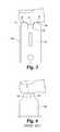
- FIG. 4is a top perspective view of an alternate embodiment of an integrated lancet testing device.
- FIG. 5is a back perspective view of the FIG. 4 device with the lancet.
- FIG. 6is a top view of a prior art integrated lancet testing device pressed against a finger of a user.
- FIG. 7is a top perspective view of the FIG. 1 device extending from a test meter.
- Integrated lancing test strip 20is also commonly referred to as a lancet integrated test strip or “LIT” for short.
- Integrated lancing test strip 20is configured to stabilize the skin near an incision site, form an incision in skin, collect a body fluid sample from the incision, and analyze the body fluid sample.
- the integrated lancing test strip 20includes a lancet or incision forming member 22 for forming an incision in tissue and a test strip 24 . Both the lancet 22 and the test strip 24 are substantially flat such that the integrated lancing test strip 20 has an overall flat appearance.
- the integrated lancing test strip 20Since the general overall appearance of the integrated lancing test strip 20 is flat, multiple integrated lancing test strips 20 can be incorporated into magazines, cassettes, drums, cartridges and the like, which allows a plurality of integrated lancing test strips 20 to be stacked upon one another in a magazine or rolled around a reel in a cassette. As described in more detail below, the substantially flat shape of the integrated lancing test strip 20 allows the test strip 24 to be manufactured with a continuous process in which layers of component materials can be layered to form contiguous strips of test strips 24 that can be cut to form individual test strips. Moreover, the layers of materials and the test chemistry or reagent that form test strips 24 can be cut or stamped to form a first skin contacting tab 42 and a second skin contacting tab 44 in each test strip 24 .
- the lancet 22has a lancet tip 30 connected to a lancet body 32 .
- the lancet 22also includes a lancet end portion 34 connected to lancet body 32 .
- the lancet body 32defines a guide opening 36 sized to receive a driver configured to engage the guide opening 36 to move the lancet 22 to form an incision in skin.
- the guide opening 36is aligned with a depth limiting opening 40 in test strip 24 , as described in more detail below. Additional details about a driver and other types of firing mechanisms are provided in U.S.
- the test strip 24is an electrochemical type test strip.
- the test strip 24includes a modified version of an ACCU-CHEK® brand test strip (Roche Diagnostics GmbH, Mannheim, Germany), but it is envisioned that other types of test strips can be used.
- the test strip 24in other embodiments can include an optical type test strip or can analyze fluid samples in other manners.
- the test strip 24includes a first skin contacting tab 42 and a second skin contacting tab 44 .
- the test strip 24also includes a mid-portion 46 connected to the first skin contacting tab 42 and the second skin contacting tab 44 .
- the test strip 24includes an end portion 48 connected to the mid-portion 46 .
- the mid-portion 46defines a depth limiting opening 40 sized to receive a portion of a driver and/or opening 40 is sized for engagement with a gripper.
- the opening 40is a slot sized to receive a lancet gripper device.
- the test strip 24includes a test area 50 positioned between the first skin contacting tab 42 and the second skin contacting tab 44 .
- the test area 50is designed to allow body fluid to move from an incision in skin up the test area 50 via capillary action.
- the test area 50includes a reagent and is disposed between a first panel 52 and a second panel 54 and extends to a front edge of the first panel 52 and the second panel 54 .
- the first panel 52is laminated to the second panel 54 .
- First panel 52 and second panel 54can be continuous sheets of material that are laminated together to form contiguous strips of test strips 24 . These contiguous strips of test strips 24 can be cut to form a plurality of individual test strips 24 . In one embodiment, the front edge of the first panel 52 and the second panel 54 are cut to form the first skin contacting tab 42 and the second skin contacting tab 44 . In another embodiment, the front edge of the first panel 52 and the second panel 54 are stamped to form the first skin contacting tab 42 and the second skin contacting tab 44 . End portion 48 defines an opening 58 sized to attach or fix the test strip 24 to a test meter, a testing device, or a driver.
- the first skin contacting tab 42has a skin contacting portion 60 that is configured to contact skin near an incision site. As illustrated, skin contacting portion 60 is semi-circular in shape. The first skin contacting tab 42 also includes a leg portion 62 next to the skin contacting portion 60 . The second skin contacting tab 44 includes a skin contacting portion 70 that is configured to contact skin near an incision site. The skin contacting portion 70 is semi-circular in shape. Skin contacting portion 60 and skin contacting portion 70 can be shaped the same or different from each other. The second skin contacting tab 44 includes a leg portion 72 next to skin contacting portion 70 .
- skin contacting portion 60 and skin contacting portion 70each have a radius of approximately 1.625 millimeters and leg portion 62 and leg portion 72 each have a width, W, of approximately 3.25 millimeters.
- test area 50has a width, WW, of approximately 2.5 millimeters.
- the test strip 24has a thickness of about 0.4 to 0.8 millimeters.
- FIG. 3illustrates the position of the test strip 24 in relation to skin S prior to an incision being formed in skin S.
- Test strip 24is positioned in a housing 100 .
- Housing 100can also be configured to contact skin S.
- first skin contacting portion 60 and second skin contacting portion 70are pressed against skin S.
- skin Sis stretched between first skin contacting portion 60 and second skin contacting portion 70 .
- skin S between first skin contacting portion 60 and second skin contacting portion 70is bulged towards test area 50 to express a bodily fluid sample.
- First skin contacting portion 60 and second skin contacting portion 70are sized so as to not apply force to skin S that will close an incision once it is formed.
- an incision in skin Sis formed with lancet tip 30 .
- Lancet tip 30pierces skin S without depressing skin S between first skin contacting portion 60 and second skin contacting portion 70 because skin S is pulled taut. Therefore an incision in skin S can be formed to an accurate depth.
- the test area 50is configured to collect a body fluid sample via capillary action. After the body fluid sampling event is complete, the used and contaminated integrated lancing test strip 20 is disposed of.
- the integrated lancing test strip 20is used with a housing having an opening or a mechanism sized to express body fluid to an incision site when pressed against skin. Some other examples of mechanisms sized to express body fluid to an incision site are a finger cone or a ring attached to the housing at the opening.
- the integrated lancing test strip 20is used with a test meter 200 . Beneficially, as the integrated lancing test strip 20 is pressed against skin, the skin is stretched before the lancet 22 forms an incision in skin. Therefore, depression of the skin by a lancet tip and correspondingly an uncertain incision depth are avoided with the first skin contacting tab 42 and the second skin contacting tab 44 .
- the lancet 22forms an incision in skin to an accurate depth for each lancing event with the first skin contacting tab 42 and the second skin contacting tab 44 .
- the first skin contacting tab 42 and the second skin contacting tab 44ensure reproducibility of an accurate incision depth by the lancet 22 .
- Test strip 320includes a substantially straight front end 322 which contacts a finger to flatten skin S.
- Test strip 320includes a test area 324 .
- Front end 322is pressed against a finger therefore skin S is not bulged towards test area 324 and body fluid is not expressed to skin S.
- skin Sis not stretched taut by the substantially straight front end 322 therefore the pricking depth cannot be regulated and depression of skin S may not be avoided.
- Integrated lancing test strip 120is configured to stabilize the skin near an incision site, form an incision in skin, collect a body fluid sample from the incision, and analyze the body fluid sample.
- integrated lancing test strip 120shares a number of features in common with integrated lancing test strip 20 illustrated in FIGS. 1, 2, and 3 . Therefore for the sake of brevity, common features from the integrated lancing test strip 120 and the integrated lancing test strip 20 will not be discussed.
- test strip 124includes a first skin contacting tab 142 and a second skin contacting tab 144 .
- the first skin contacting tab 142has a first skin contacting portion 160 that is configured to contact skin near an incision site. As illustrated, first skin contacting portion 160 is triangular in shape. The first skin contacting tab 142 also includes a leg portion 162 next to the first skin contacting portion 160 .
- the second skin contacting tab 144includes a second skin contacting portion 170 that is configured to contact skin near an incision site. The second skin contacting portion 170 is triangular in shape. The second skin contacting tab 144 includes a leg portion 172 next to second skin contacting portion 170 .
- first skin contacting portion 160 and second skin contacting portion 170each have a width, W, of approximately 3.25 millimeters.
- test area 150has a width, WW, of approximately 2.5 millimeters.
- Test strip 24in one embodiment has a thickness of about 0.4 to 0.8 millimeters.
- integrated lancing test strip 120is similar to integrated lancing test strip 20 .
- First skin contacting portion 160 and second skin contacting portion 170are pressed against skin. The skin is stretched between first skin contacting portion 160 and second skin contacting portion 170 . The skin between first skin contacting portion 160 and second skin contacting portion 170 is also bulged towards a test area 150 to express a bodily fluid sample.
- First skin contacting portion 160 and second skin contacting portion 170are sized such that the incision remains open once it is formed by a lancet 122 .
- Next an incision in skinis formed with a lancet tip 130 . Lancet tip 130 pierces the skin without depressing the skin between the first skin contacting portion 160 and second skin contacting portion 170 . Therefore an incision in skin to an accurate depth can be formed.
- the test area 150is configured to collect a body fluid sample.
- the integrated lancing test strip 20 and the integrated lancing test strip 120can include combinations of the above-mentioned components in addition to other components.
- the integrated lancing test strip 20 and the integrated lancing test strip 120can include bendable wicking flags and the like that also contact the skin during sampling.
- the skin contacting portionshave a semi-circular or a triangular shape, but the skin contacting portions may be shaped differently in other embodiments. It should be recognized that the skin contacting portions can take different forms in other embodiments. For example, the skin contacting portions can be rectangular, square, oval, or polygonal.
- the integrated lancing test strip 20 and the integrated lancing test strip 120can include either photometric or electrochemical test strips.
- the term “lancet”is used in a broader sense and is meant to include any sharp and/or pointed structure for cutting incisions in tissue, such as a needle, blade, knife, scalpel, and the like.
- the lancetcan be, whole or in part, hollow and/or solid.
- the lancetcan be round, flat and/or have other cross-sectional shapes. Further, the lancet can have a single cutting surface or multiple cutting surfaces.
- the lancetcan also be a microsampler.
Landscapes
- Health & Medical Sciences (AREA)
- Life Sciences & Earth Sciences (AREA)
- Engineering & Computer Science (AREA)
- Hematology (AREA)
- General Health & Medical Sciences (AREA)
- Animal Behavior & Ethology (AREA)
- Public Health (AREA)
- Biomedical Technology (AREA)
- Heart & Thoracic Surgery (AREA)
- Medical Informatics (AREA)
- Molecular Biology (AREA)
- Surgery (AREA)
- Biophysics (AREA)
- Physics & Mathematics (AREA)
- Pathology (AREA)
- Veterinary Medicine (AREA)
- Chemical & Material Sciences (AREA)
- Dermatology (AREA)
- Manufacturing & Machinery (AREA)
- Analytical Chemistry (AREA)
- Clinical Laboratory Science (AREA)
- Chemical Kinetics & Catalysis (AREA)
- Dispersion Chemistry (AREA)
- Pain & Pain Management (AREA)
- Measurement Of The Respiration, Hearing Ability, Form, And Blood Characteristics Of Living Organisms (AREA)
Abstract
Description
Claims (12)
Priority Applications (1)
| Application Number | Priority Date | Filing Date | Title |
|---|---|---|---|
| US13/273,409US9475044B2 (en) | 2009-08-20 | 2011-10-14 | Test strip with a shaped tip for skin straightening |
Applications Claiming Priority (2)
| Application Number | Priority Date | Filing Date | Title |
|---|---|---|---|
| US12/544,296US8061004B2 (en) | 2009-08-20 | 2009-08-20 | Method of manufacturing a test strip |
| US13/273,409US9475044B2 (en) | 2009-08-20 | 2011-10-14 | Test strip with a shaped tip for skin straightening |
Related Parent Applications (1)
| Application Number | Title | Priority Date | Filing Date |
|---|---|---|---|
| US12/544,296DivisionUS8061004B2 (en) | 2009-08-20 | 2009-08-20 | Method of manufacturing a test strip |
Publications (2)
| Publication Number | Publication Date |
|---|---|
| US20120035506A1 US20120035506A1 (en) | 2012-02-09 |
| US9475044B2true US9475044B2 (en) | 2016-10-25 |
Family
ID=43499807
Family Applications (2)
| Application Number | Title | Priority Date | Filing Date |
|---|---|---|---|
| US12/544,296Expired - Fee RelatedUS8061004B2 (en) | 2009-08-20 | 2009-08-20 | Method of manufacturing a test strip |
| US13/273,409Expired - Fee RelatedUS9475044B2 (en) | 2009-08-20 | 2011-10-14 | Test strip with a shaped tip for skin straightening |
Family Applications Before (1)
| Application Number | Title | Priority Date | Filing Date |
|---|---|---|---|
| US12/544,296Expired - Fee RelatedUS8061004B2 (en) | 2009-08-20 | 2009-08-20 | Method of manufacturing a test strip |
Country Status (4)
| Country | Link |
|---|---|
| US (2) | US8061004B2 (en) |
| EP (1) | EP2467207B1 (en) |
| CN (1) | CN102470366B (en) |
| WO (1) | WO2011020598A2 (en) |
Families Citing this family (6)
| Publication number | Priority date | Publication date | Assignee | Title |
|---|---|---|---|---|
| US7802467B2 (en) | 2006-12-22 | 2010-09-28 | Abbott Diabetes Care Inc. | Analyte sensors and methods of use |
| US9554736B2 (en) | 2011-11-29 | 2017-01-31 | Teleflex Medical Incorporated | Device with integrated allergy testing |
| JP6000369B2 (en)* | 2011-11-29 | 2016-09-28 | テレフレックス メディカル インコーポレイテッドTeleflex Medical Incorporated | Integrated allergy testing instrument |
| US10296362B2 (en)* | 2014-02-26 | 2019-05-21 | Red Hat Israel, Ltd. | Execution of a script based on properties of a virtual device associated with a virtual machine |
| KR102200165B1 (en)* | 2017-08-02 | 2021-01-08 | 에프. 호프만-라 로슈 아게 | Glucose test arrangement and method |
| USD912843S1 (en)* | 2018-11-06 | 2021-03-09 | Lumiradx Uk Ltd | Test strip |
Citations (25)
| Publication number | Priority date | Publication date | Assignee | Title |
|---|---|---|---|---|
| US6132449A (en) | 1999-03-08 | 2000-10-17 | Agilent Technologies, Inc. | Extraction and transportation of blood for analysis |
| US6207000B1 (en)* | 1998-04-08 | 2001-03-27 | Roche Diagnostics Gmbh | Process for the production of analytical devices |
| US6258075B1 (en) | 1999-04-08 | 2001-07-10 | The Procter & Gamble Company | Tampon with enhanced leakage protection |
| US6306152B1 (en) | 1999-03-08 | 2001-10-23 | Agilent Technologies, Inc. | Lancet device with skin movement control and ballistic preload |
| US20020168290A1 (en) | 2002-05-09 | 2002-11-14 | Yuzhakov Vadim V. | Physiological sample collection devices and methods of using the same |
| US6561989B2 (en) | 2000-07-10 | 2003-05-13 | Bayer Healthcare, Llc | Thin lance and test sensor having same |
| US20030146110A1 (en)* | 2002-02-01 | 2003-08-07 | Karinka Shirdhara Alva | Electrochemical biosensor strip for analysis of liquid samples |
| US20040127818A1 (en) | 2002-12-27 | 2004-07-01 | Roe Steven N. | Precision depth control lancing tip |
| US20040127929A1 (en) | 2002-12-30 | 2004-07-01 | Roe Steven N. | Flexible test strip lancet device |
| US20040138688A1 (en) | 2002-10-09 | 2004-07-15 | Jean Pierre Giraud | Lancet system including test strips and cassettes for drawing and sampling bodily material |
| US20050019212A1 (en)* | 2003-06-20 | 2005-01-27 | Bhullar Raghbir S. | Test strip with flared sample receiving chamber |
| US20050283094A1 (en) | 2004-06-21 | 2005-12-22 | Detlef Thym | Disposable lancet and lancing cap combination for increased hygiene |
| WO2006037646A2 (en) | 2004-10-08 | 2006-04-13 | Roche Diagnostics Gmbh | Integrated lancing test strip with capillary transfer sheet |
| US20060131171A1 (en)* | 2003-06-19 | 2006-06-22 | Arkray, Inc. | Analysis implement with opening in insulation film |
| US20060200045A1 (en) | 2005-03-02 | 2006-09-07 | Roe Steven N | Dynamic integrated lancing test strip with sterility cover |
| US20070149897A1 (en)* | 2005-11-30 | 2007-06-28 | Abbott Diabetes Care, Inc. | Integrated Sensor for Analyzing Biological Samples |
| US20070167869A1 (en) | 2005-03-02 | 2007-07-19 | Roe Steven N | System and method for breaking a sterility seal to engage a lancet |
| US20070173740A1 (en)* | 2006-01-05 | 2007-07-26 | Roche Diagnostics Operations, Inc. | Lancet integrated test element tape dispenser |
| US20070173739A1 (en)* | 2006-01-26 | 2007-07-26 | Chan Frank A | Stack magazine system |
| US7299081B2 (en) | 2004-06-15 | 2007-11-20 | Abbott Laboratories | Analyte test device |
| US20070278097A1 (en)* | 2003-06-20 | 2007-12-06 | Bhullar Raghbir S | Biosensor with laser-sealed capillary space and method of making |
| US20080060424A1 (en)* | 2005-03-22 | 2008-03-13 | Branislav Babic | Test element for analyzing body fluids |
| US7351212B2 (en) | 2002-12-30 | 2008-04-01 | Roche Diagnostics Operations, Inc. | Blood acquisition suspension system |
| US20080208078A1 (en) | 2007-02-28 | 2008-08-28 | Home Diagnostics, Inc. | Test strip with integrated lancet |
| US7476202B2 (en) | 2001-06-08 | 2009-01-13 | Roche Diagnostics Operations, Inc. | Sampling devices and methods utilizing a horizontal capillary test strip |
- 2009
- 2009-08-20USUS12/544,296patent/US8061004B2/ennot_activeExpired - Fee Related
- 2010
- 2010-08-18EPEP10744893.8Apatent/EP2467207B1/ennot_activeNot-in-force
- 2010-08-18CNCN201080036799.XApatent/CN102470366B/ennot_activeExpired - Fee Related
- 2010-08-18WOPCT/EP2010/005057patent/WO2011020598A2/enactiveApplication Filing
- 2011
- 2011-10-14USUS13/273,409patent/US9475044B2/ennot_activeExpired - Fee Related
Patent Citations (30)
| Publication number | Priority date | Publication date | Assignee | Title |
|---|---|---|---|---|
| US6207000B1 (en)* | 1998-04-08 | 2001-03-27 | Roche Diagnostics Gmbh | Process for the production of analytical devices |
| US6132449A (en) | 1999-03-08 | 2000-10-17 | Agilent Technologies, Inc. | Extraction and transportation of blood for analysis |
| US6306152B1 (en) | 1999-03-08 | 2001-10-23 | Agilent Technologies, Inc. | Lancet device with skin movement control and ballistic preload |
| US6258075B1 (en) | 1999-04-08 | 2001-07-10 | The Procter & Gamble Company | Tampon with enhanced leakage protection |
| US6561989B2 (en) | 2000-07-10 | 2003-05-13 | Bayer Healthcare, Llc | Thin lance and test sensor having same |
| US7476202B2 (en) | 2001-06-08 | 2009-01-13 | Roche Diagnostics Operations, Inc. | Sampling devices and methods utilizing a horizontal capillary test strip |
| US20030146110A1 (en)* | 2002-02-01 | 2003-08-07 | Karinka Shirdhara Alva | Electrochemical biosensor strip for analysis of liquid samples |
| US20020168290A1 (en) | 2002-05-09 | 2002-11-14 | Yuzhakov Vadim V. | Physiological sample collection devices and methods of using the same |
| US20040138688A1 (en) | 2002-10-09 | 2004-07-15 | Jean Pierre Giraud | Lancet system including test strips and cassettes for drawing and sampling bodily material |
| US20040127818A1 (en) | 2002-12-27 | 2004-07-01 | Roe Steven N. | Precision depth control lancing tip |
| US20040236251A1 (en) | 2002-12-27 | 2004-11-25 | Roe Steven N. | Precision depth control lancing tip |
| US20080147107A1 (en) | 2002-12-27 | 2008-06-19 | Roe Steven N | Precision depth control lancing tip |
| US20040127929A1 (en) | 2002-12-30 | 2004-07-01 | Roe Steven N. | Flexible test strip lancet device |
| US7351212B2 (en) | 2002-12-30 | 2008-04-01 | Roche Diagnostics Operations, Inc. | Blood acquisition suspension system |
| US20060131171A1 (en)* | 2003-06-19 | 2006-06-22 | Arkray, Inc. | Analysis implement with opening in insulation film |
| US20050019212A1 (en)* | 2003-06-20 | 2005-01-27 | Bhullar Raghbir S. | Test strip with flared sample receiving chamber |
| US20070278097A1 (en)* | 2003-06-20 | 2007-12-06 | Bhullar Raghbir S | Biosensor with laser-sealed capillary space and method of making |
| US7299081B2 (en) | 2004-06-15 | 2007-11-20 | Abbott Laboratories | Analyte test device |
| US20050283094A1 (en) | 2004-06-21 | 2005-12-22 | Detlef Thym | Disposable lancet and lancing cap combination for increased hygiene |
| WO2006037646A2 (en) | 2004-10-08 | 2006-04-13 | Roche Diagnostics Gmbh | Integrated lancing test strip with capillary transfer sheet |
| US20070167869A1 (en) | 2005-03-02 | 2007-07-19 | Roe Steven N | System and method for breaking a sterility seal to engage a lancet |
| US20060200045A1 (en) | 2005-03-02 | 2006-09-07 | Roe Steven N | Dynamic integrated lancing test strip with sterility cover |
| US7815579B2 (en) | 2005-03-02 | 2010-10-19 | Roche Diagnostics Operations, Inc. | Dynamic integrated lancing test strip with sterility cover |
| US7935063B2 (en) | 2005-03-02 | 2011-05-03 | Roche Diagnostics Operations, Inc. | System and method for breaking a sterility seal to engage a lancet |
| US20080060424A1 (en)* | 2005-03-22 | 2008-03-13 | Branislav Babic | Test element for analyzing body fluids |
| US20070149897A1 (en)* | 2005-11-30 | 2007-06-28 | Abbott Diabetes Care, Inc. | Integrated Sensor for Analyzing Biological Samples |
| US20070173740A1 (en)* | 2006-01-05 | 2007-07-26 | Roche Diagnostics Operations, Inc. | Lancet integrated test element tape dispenser |
| US7481777B2 (en)* | 2006-01-05 | 2009-01-27 | Roche Diagnostics Operations, Inc. | Lancet integrated test element tape dispenser |
| US20070173739A1 (en)* | 2006-01-26 | 2007-07-26 | Chan Frank A | Stack magazine system |
| US20080208078A1 (en) | 2007-02-28 | 2008-08-28 | Home Diagnostics, Inc. | Test strip with integrated lancet |
Non-Patent Citations (2)
| Title |
|---|
| China Patent Application No. 201080036799.X Search Report mailed Sep. 3, 2013. |
| International Application No. PCT/EP2010/005057 International Search Report and Written Opinion, mailed Feb. 14, 2011. |
Also Published As
| Publication number | Publication date |
|---|---|
| WO2011020598A2 (en) | 2011-02-24 |
| CN102470366A (en) | 2012-05-23 |
| US8061004B2 (en) | 2011-11-22 |
| HK1170977A1 (en) | 2013-03-15 |
| US20110046453A1 (en) | 2011-02-24 |
| EP2467207A2 (en) | 2012-06-27 |
| WO2011020598A3 (en) | 2011-04-14 |
| EP2467207B1 (en) | 2017-11-01 |
| US20120035506A1 (en) | 2012-02-09 |
| CN102470366B (en) | 2014-12-03 |
Similar Documents
| Publication | Publication Date | Title |
|---|---|---|
| US9475044B2 (en) | Test strip with a shaped tip for skin straightening | |
| US8157750B2 (en) | Integrated analytical test element | |
| US7670301B2 (en) | Integrated disposable for automatic or manual blood dosing | |
| US6537264B1 (en) | Device and method for enhancing transdermal flux of agents being sampled | |
| US5054499A (en) | Disposable skin perforator and blood testing device | |
| US20080269791A1 (en) | Kinked lancet | |
| EP1714614B1 (en) | Analyzing means | |
| RU2351279C2 (en) | Packed medical device, set, method for operation elements penetrating skin tissues | |
| US7377903B2 (en) | Split tip expression device | |
| EP1880671B1 (en) | Lancet wheel | |
| EP1868491B1 (en) | Analyzing means with lancet and test element | |
| US20100010374A1 (en) | Body fluid sampling device - sampling site interface | |
| JP2009106737A (en) | Lancet wheel | |
| US20090306696A1 (en) | Lancet | |
| US9055898B2 (en) | Lancet release mechanism | |
| US9375175B2 (en) | Lancing device | |
| MXPA04006476A (en) | Improved method of lancing skin for the extraction of blood. | |
| HK1170977B (en) | Test strip with a shaped tip for skin straightening | |
| EP1894526A1 (en) | Lancet | |
| JP4894038B2 (en) | Biosensor cartridge | |
| JP2008194270A (en) | Biosensor cartridge and manufacturing method thereof |
Legal Events
| Date | Code | Title | Description |
|---|---|---|---|
| AS | Assignment | Owner name:ROCHE DIAGNOSTICS GMBH, GERMANY Free format text:ASSIGNMENT OF ASSIGNORS INTEREST;ASSIGNOR:KEIL, MICHAEL;REEL/FRAME:027063/0603 Effective date:20090827 Owner name:ROCHE DIAGNOSTICS OPERATIONS, INC., INDIANA Free format text:ASSIGNMENT OF ASSIGNORS INTEREST;ASSIGNOR:ROCHE DIAGNOSTICS GMBH;REEL/FRAME:027063/0612 Effective date:20090831 | |
| AS | Assignment | Owner name:ROCHE DIABETES CARE, INC., INDIANA Free format text:ASSIGNMENT OF ASSIGNORS INTEREST;ASSIGNOR:ROCHE DIAGNOSTICS OPERATIONS, INC.;REEL/FRAME:036008/0670 Effective date:20150302 | |
| ZAAA | Notice of allowance and fees due | Free format text:ORIGINAL CODE: NOA | |
| ZAAB | Notice of allowance mailed | Free format text:ORIGINAL CODE: MN/=. | |
| STCF | Information on status: patent grant | Free format text:PATENTED CASE | |
| CC | Certificate of correction | ||
| MAFP | Maintenance fee payment | Free format text:PAYMENT OF MAINTENANCE FEE, 4TH YEAR, LARGE ENTITY (ORIGINAL EVENT CODE: M1551); ENTITY STATUS OF PATENT OWNER: LARGE ENTITY Year of fee payment:4 | |
| FEPP | Fee payment procedure | Free format text:MAINTENANCE FEE REMINDER MAILED (ORIGINAL EVENT CODE: REM.); ENTITY STATUS OF PATENT OWNER: LARGE ENTITY | |
| LAPS | Lapse for failure to pay maintenance fees | Free format text:PATENT EXPIRED FOR FAILURE TO PAY MAINTENANCE FEES (ORIGINAL EVENT CODE: EXP.); ENTITY STATUS OF PATENT OWNER: LARGE ENTITY | |
| STCH | Information on status: patent discontinuation | Free format text:PATENT EXPIRED DUE TO NONPAYMENT OF MAINTENANCE FEES UNDER 37 CFR 1.362 | |
| FP | Lapsed due to failure to pay maintenance fee | Effective date:20241025 |