US9474906B2 - Systems and methods for restoring muscle function to the lumbar spine - Google Patents
Systems and methods for restoring muscle function to the lumbar spineDownload PDFInfo
- Publication number
- US9474906B2 US9474906B2US14/792,430US201514792430AUS9474906B2US 9474906 B2US9474906 B2US 9474906B2US 201514792430 AUS201514792430 AUS 201514792430AUS 9474906 B2US9474906 B2US 9474906B2
- Authority
- US
- United States
- Prior art keywords
- ipg
- activator
- electrically stimulating
- stimulation
- electrodes
- Prior art date
- Legal status (The legal status is an assumption and is not a legal conclusion. Google has not performed a legal analysis and makes no representation as to the accuracy of the status listed.)
- Active
Links
Images


Classifications
- A—HUMAN NECESSITIES
- A61—MEDICAL OR VETERINARY SCIENCE; HYGIENE
- A61N—ELECTROTHERAPY; MAGNETOTHERAPY; RADIATION THERAPY; ULTRASOUND THERAPY
- A61N1/00—Electrotherapy; Circuits therefor
- A61N1/18—Applying electric currents by contact electrodes
- A61N1/32—Applying electric currents by contact electrodes alternating or intermittent currents
- A61N1/36—Applying electric currents by contact electrodes alternating or intermittent currents for stimulation
- A61N1/3605—Implantable neurostimulators for stimulating central or peripheral nerve system
- A61N1/3606—Implantable neurostimulators for stimulating central or peripheral nerve system adapted for a particular treatment
- A61N1/36071—Pain
- A—HUMAN NECESSITIES
- A61—MEDICAL OR VETERINARY SCIENCE; HYGIENE
- A61N—ELECTROTHERAPY; MAGNETOTHERAPY; RADIATION THERAPY; ULTRASOUND THERAPY
- A61N1/00—Electrotherapy; Circuits therefor
- A61N1/02—Details
- A61N1/04—Electrodes
- A61N1/05—Electrodes for implantation or insertion into the body, e.g. heart electrode
- A61N1/0551—Spinal or peripheral nerve electrodes
- A61N1/0558—Anchoring or fixation means therefor
- A—HUMAN NECESSITIES
- A61—MEDICAL OR VETERINARY SCIENCE; HYGIENE
- A61N—ELECTROTHERAPY; MAGNETOTHERAPY; RADIATION THERAPY; ULTRASOUND THERAPY
- A61N1/00—Electrotherapy; Circuits therefor
- A61N1/18—Applying electric currents by contact electrodes
- A61N1/32—Applying electric currents by contact electrodes alternating or intermittent currents
- A61N1/36—Applying electric currents by contact electrodes alternating or intermittent currents for stimulation
- A61N1/36003—Applying electric currents by contact electrodes alternating or intermittent currents for stimulation of motor muscles, e.g. for walking assistance
- A—HUMAN NECESSITIES
- A61—MEDICAL OR VETERINARY SCIENCE; HYGIENE
- A61N—ELECTROTHERAPY; MAGNETOTHERAPY; RADIATION THERAPY; ULTRASOUND THERAPY
- A61N1/00—Electrotherapy; Circuits therefor
- A61N1/18—Applying electric currents by contact electrodes
- A61N1/32—Applying electric currents by contact electrodes alternating or intermittent currents
- A61N1/36—Applying electric currents by contact electrodes alternating or intermittent currents for stimulation
- A61N1/3605—Implantable neurostimulators for stimulating central or peripheral nerve system
- A61N1/3606—Implantable neurostimulators for stimulating central or peripheral nerve system adapted for a particular treatment
- A61N1/36067—Movement disorders, e.g. tremor or Parkinson disease
- A—HUMAN NECESSITIES
- A61—MEDICAL OR VETERINARY SCIENCE; HYGIENE
- A61N—ELECTROTHERAPY; MAGNETOTHERAPY; RADIATION THERAPY; ULTRASOUND THERAPY
- A61N1/00—Electrotherapy; Circuits therefor
- A61N1/18—Applying electric currents by contact electrodes
- A61N1/32—Applying electric currents by contact electrodes alternating or intermittent currents
- A61N1/36—Applying electric currents by contact electrodes alternating or intermittent currents for stimulation
- A61N1/3605—Implantable neurostimulators for stimulating central or peripheral nerve system
- A61N1/36125—Details of circuitry or electric components
- A—HUMAN NECESSITIES
- A61—MEDICAL OR VETERINARY SCIENCE; HYGIENE
- A61N—ELECTROTHERAPY; MAGNETOTHERAPY; RADIATION THERAPY; ULTRASOUND THERAPY
- A61N1/00—Electrotherapy; Circuits therefor
- A61N1/18—Applying electric currents by contact electrodes
- A61N1/32—Applying electric currents by contact electrodes alternating or intermittent currents
- A61N1/36—Applying electric currents by contact electrodes alternating or intermittent currents for stimulation
- A61N1/3605—Implantable neurostimulators for stimulating central or peripheral nerve system
- A61N1/36128—Control systems
- A61N1/36146—Control systems specified by the stimulation parameters
- A61N1/36167—Timing, e.g. stimulation onset
- A61N1/36175—Pulse width or duty cycle
- A—HUMAN NECESSITIES
- A61—MEDICAL OR VETERINARY SCIENCE; HYGIENE
- A61N—ELECTROTHERAPY; MAGNETOTHERAPY; RADIATION THERAPY; ULTRASOUND THERAPY
- A61N1/00—Electrotherapy; Circuits therefor
- A61N1/18—Applying electric currents by contact electrodes
- A61N1/32—Applying electric currents by contact electrodes alternating or intermittent currents
- A61N1/36—Applying electric currents by contact electrodes alternating or intermittent currents for stimulation
- A61N1/3605—Implantable neurostimulators for stimulating central or peripheral nerve system
- A61N1/36128—Control systems
- A61N1/36146—Control systems specified by the stimulation parameters
- A61N1/36182—Direction of the electrical field, e.g. with sleeve around stimulating electrode
- A61N1/36185—Selection of the electrode configuration
- A—HUMAN NECESSITIES
- A61—MEDICAL OR VETERINARY SCIENCE; HYGIENE
- A61N—ELECTROTHERAPY; MAGNETOTHERAPY; RADIATION THERAPY; ULTRASOUND THERAPY
- A61N1/00—Electrotherapy; Circuits therefor
- A61N1/18—Applying electric currents by contact electrodes
- A61N1/32—Applying electric currents by contact electrodes alternating or intermittent currents
- A61N1/36—Applying electric currents by contact electrodes alternating or intermittent currents for stimulation
- A61N1/372—Arrangements in connection with the implantation of stimulators
- A61N1/37211—Means for communicating with stimulators
- A61N1/37217—Means for communicating with stimulators characterised by the communication link, e.g. acoustic or tactile
- A61N1/37223—Circuits for electromagnetic coupling
- A61N1/37229—Shape or location of the implanted or external antenna
- A—HUMAN NECESSITIES
- A61—MEDICAL OR VETERINARY SCIENCE; HYGIENE
- A61N—ELECTROTHERAPY; MAGNETOTHERAPY; RADIATION THERAPY; ULTRASOUND THERAPY
- A61N1/00—Electrotherapy; Circuits therefor
- A61N1/18—Applying electric currents by contact electrodes
- A61N1/32—Applying electric currents by contact electrodes alternating or intermittent currents
- A61N1/36—Applying electric currents by contact electrodes alternating or intermittent currents for stimulation
- A61N1/372—Arrangements in connection with the implantation of stimulators
- A61N1/37211—Means for communicating with stimulators
- A61N1/37235—Aspects of the external programmer
- A61N1/37247—User interfaces, e.g. input or presentation means
- A—HUMAN NECESSITIES
- A61—MEDICAL OR VETERINARY SCIENCE; HYGIENE
- A61N—ELECTROTHERAPY; MAGNETOTHERAPY; RADIATION THERAPY; ULTRASOUND THERAPY
- A61N2/00—Magnetotherapy
- A61N2/004—Magnetotherapy specially adapted for a specific therapy
- A61N2/008—Magnetotherapy specially adapted for a specific therapy for pain treatment or analgesia
- A—HUMAN NECESSITIES
- A61—MEDICAL OR VETERINARY SCIENCE; HYGIENE
- A61N—ELECTROTHERAPY; MAGNETOTHERAPY; RADIATION THERAPY; ULTRASOUND THERAPY
- A61N2/00—Magnetotherapy
- A61N2/06—Magnetotherapy using magnetic fields produced by permanent magnets
- A—HUMAN NECESSITIES
- A61—MEDICAL OR VETERINARY SCIENCE; HYGIENE
- A61N—ELECTROTHERAPY; MAGNETOTHERAPY; RADIATION THERAPY; ULTRASOUND THERAPY
- A61N1/00—Electrotherapy; Circuits therefor
- A61N1/18—Applying electric currents by contact electrodes
- A61N1/32—Applying electric currents by contact electrodes alternating or intermittent currents
- A61N1/36—Applying electric currents by contact electrodes alternating or intermittent currents for stimulation
- A61N1/3605—Implantable neurostimulators for stimulating central or peripheral nerve system
- A61N1/36128—Control systems
- A61N1/36146—Control systems specified by the stimulation parameters
- A61N1/3615—Intensity
- A61N1/36157—Current
Definitions
- This applicationgenerally relates to systems and methods for neuromuscular electrical stimulation, including stimulation of tissue associated with control of the lumbar spine for treatment of back pain.
- the human backis a complicated structure including bones, muscles, ligaments, tendons, nerves and other structures.
- the spinal columnhas interleaved vertebral bodies and intervertebral discs, and permits motion in several planes including flexion-extension, lateral bending, axial rotation, longitudinal axial distraction-compression, anterior-posterior sagittal translation, and left-right horizontal translation.
- the spineprovides connection points for a complex collection of muscles that are subject to both voluntary and involuntary control.
- Back pain in the lower or lumbar region of the backis common. In many cases, the cause of back pain is unknown. It is believed that some cases of back pain are caused by abnormal mechanics of the spinal column. Degenerative changes, injury of the ligaments, acute trauma, or repetitive microtrauma may lead to back pain via inflammation, biochemical and nutritional changes, immunological factors, changes in the structure or material of the endplates or discs, and pathology of neural structures.
- the spinal stabilization systemmay be conceptualized to include three subsystems: 1) the spinal column, which provides intrinsic mechanical stability; 2) the spinal muscles, which surround the spinal column and provide dynamic stability; and 3) the neuromotor control unit, which evaluates and determines requirements for stability via a coordinated muscle response.
- these three subsystemswork together to provide mechanical stability. It is applicant's realization that low back pain results from dysfunction of these subsystems.
- the spinal columnconsists of vertebrae and ligaments, e.g. spinal ligaments, disc annulus, and facet capsules.
- ligamentse.g. spinal ligaments, disc annulus, and facet capsules.
- the spinal columnalso has a transducer function, to generate signals describing spinal posture, motions, and loads via mechanoreceptors present in the ligaments, facet capsules, disc annulus, and other connective tissues. These mechanoreceptors provide information to the neuromuscular control unit, which generates muscle response patterns to activate and coordinate the spinal muscles to provide muscle mechanical stability. Ligament injury, fatigue, and viscoelastic creep may corrupt signal transduction. If spinal column structure is compromised, due to injury, degeneration, or viscoelastic creep, then muscular stability must be increased to compensate and maintain stability.
- Musclesprovide mechanical stability to the spinal column. This is apparent by viewing cross section images of the spine, as the total area of the cross sections of the muscles surrounding the spinal column is larger than the spinal column itself. Additionally, the muscles have much larger lever arms than those of the intervertebral disc and ligaments.
- the neuromuscular control unitproduces a muscle response pattern based upon several factors, including the need for spinal stability, postural control, balance, and stress reduction on various spinal components.
- the spinal stabilization systemis dysfunctional.
- mechanoreceptorsmay produce corrupted signals about vertebral position, motion, or loads, leading to an inappropriate muscle response.
- muscles themselvesmay be injured, fatigued, atrophied, or lose their strength, thus aggravating dysfunction of the spinal stabilization system.
- musclescan disrupt the spinal stabilization system by going into spasm, contracting when they should remain inactive, or contracting out of sequence with other muscles.
- muscle dysfunctionmay further compromise normal muscle activation patterns via the feedback loops.
- Trunk musclesmay be categorized into local and global muscles.
- the local muscle systemincludes deep muscles, and portions of some muscles that have their origin or insertion on the vertebrae. These local muscles control the stiffness and intervertebral relationship of the spinal segments. They provide an efficient mechanism to fine-tune the control of intervertebral motion.
- the lumbar multifiduswith its vertebra-to-vertebra attachments is an example of a muscle of the local system.
- Another exampleis the transverse abdominus, with its direct attachments to the lumbar vertebrae through the thoracolumbar fascia.
- the multifidusis the largest and most medial of the lumbar back muscles. It has a repeating series of fascicles which stem from the laminae and spinous processes of the vertebrae, and exhibit a constant pattern of attachments caudally. These fascicles are arranged in five overlapping groups such that each of the five lumbar vertebrae gives rise to one of these groups. At each segmental level, a fascicle arises from the base and caudolateral edge of the spinous process, and several fascicles arise, by way of a common tendon, from the caudal tip of the spinous process.
- the fascicles in each groupdiverge caudally to assume separate attachments to the mamillary processes, the iliac crest, and the sacrum.
- Some of the deep fibers of the fascicles that attach to the mamillary processesattach to the capsules of the facet joints next to the mamillary processes.
- the fasicles arriving from the spinous process of a given vertebraare innervated by the medial branch of the dorsal ramus that issues from below that vertebra.
- the global muscle systemencompasses the large, superficial muscles of the trunk that cross multiple motion segments, and do not have direct attachment to the vertebrae. These muscles are the torque generators for spinal motion, and control spinal orientation, balance the external loads applied to the trunk, and transfer load from the thorax to the pelvis.
- Global musclesinclude the oblique internus abdominus, the obliquus externus abdmonimus, the rectus abdominus, the lateral fibers of the quadratus lumborum, and portions of the erector spinae.
- load transmissionis painless.
- dysfunction of the spinal stabilization systemis believed to lead to instability, resulting in overloading of structures when the spine moves beyond its neutral zone.
- the neutral zoneis a range of intervertebral motion, measured from a neutral position, within which the spinal motion is produced with a minimal internal resistance.
- High loadscan lead to inflammation, disc degeneration, facet joint degeneration, and muscle fatigue. Since the endplates and annulus have a rich nerve supply, it is believed that abnormally high loads may be a cause of pain. Load transmission to the facets also may change with degenerative disc disease, leading to facet arthritis and facet pain.
- Functional electrical stimulationis the application of electrical stimulation to cause muscle contraction to re-animate limbs following damage to the nervous system such as with stroke or spine injury.
- FEShas been the subject of much prior art and scientific publications.
- the goalgenerally is to bypass the damaged nervous system and provide electrical stimulation to nerves or muscles directly which simulates the action of the nervous system.
- One lofty goal of FESis to enable paralyzed people to walk again, and that requires the coordinated action of several muscles activating several joints.
- the challenges of FESrelate to graduation of force generated by the stimulated muscles, and the control system for each muscle as well as the system as a whole to produce the desired action such as standing and walking.
- sensors in the muscle, ligaments, tendons and other anatomical structuresprovide information such as the force a muscle is exerting or the position of a joint, and that information may be used in the normal physiological control system for limb position and muscle force. This sense is referred to as proprioception.
- proprioceptionIn patients with spinal cord injury, the sensory nervous system is usually damaged as well as the motor system, and thus the afflicted person loses proprioception of what the muscle and limbs are doing.
- FES systemsoften seek to reproduce or simulate the damaged proprioceptive system with other sensors attached to a joint or muscle.
- a plurality of electrodesare used to activate selected groups of axons in a motor nerve supplying a skeletal muscle in a spinal cord patient (thereby achieving graduated control of muscle force) and one or more sensors such as an accelerometer are used to sense the position of limbs along with electrodes attached to muscles to generate an electromyogram (EMG) signal indicative of muscle activity.
- EMGelectromyogram
- U.S. Pat. No. 6,119,516 to Hockdescribes a biofeedback system, optionally including a piezoelectric element, which measures the motions of joints in the body.
- a piezoelectric crystalmay be used as a muscle activity sensor as described by U.S. Pat. No. 5,069,680 to Grandjean.
- FEShas also been used to treat spasticity, characterized by continuous increased muscle tone, involuntary muscle contractions, and altered spinal reflexes which leads to muscle tightness, awkward movements, and is often accompanied by muscle weakness.
- Spasticityresults from many causes including cerebral palsy, spinal cord injury, trauma, and neurodegenerative diseases.
- U.S. Pat. No. 7,324,853 to Ayaldescribes apparatus and method for electrically stimulating nerves that supply muscles to modify the muscle contractions that lead to spasticity.
- the apparatusincludes a control system configured to analyze electrical activity of one or more muscles, limb motion and position, and mechanical strain in an anatomical structure.
- NMESNeuromuscular Electrical Stimulation
- NMES via externally applied skin electrodeshas been used to rehabilitate skeletal muscles after injury or surgery in the associated joint. This approach is commonly used to aid in the rehabilitation of the quadriceps muscle of the leg after knee surgery. Electrical stimulation is known to not only improve the strength and endurance of the muscle, but also to restore malfunctioning motor control to a muscle. See, e.g., Gondin et al., “Electromyostimulation Training Effects on Neural Drive and Muscle Architecture”, Medicine & Science in Sports & Exercise 37, No. 8, pp. 1291-99 (August 2005).
- An implanted NMES systemhas been used to treat incontinence by stimulating nerves that supply the urinary or anal sphincter muscles.
- U.S. Pat. No. 5,199,430 to Fangdescribes implantable electronic apparatus for assisting the urinary sphincter to relax.
- the goals and challenges of rehabilitation of anatomically intact (i.e., non-pathological) neuromuscular systemsare fundamentally different from the goals and challenges of FES for treating spinal injury patients or people suffering from spasticity.
- the primary goalis to restore normal functioning of the anatomically intact neuromuscular system, whereas in spinal injury and spasticity, the primary goal is to simulate normal activity of a pathologically damaged neuromuscular system.
- the present inventionovercomes the drawbacks of previously-known systems by providing systems and methods for restoring muscle function to the lumbar spine to treat, for example, low back pain.
- the systemmay include one or more electrodes coupled to an implantable pulse generator (IPG), a handheld activator configured to be wirelessly coupled to the IPG, and an external programmer configured to be wirelessly coupled to the IPG.
- the one or more electrodesare configured to be implanted in or adjacent to tissue associated with control of the lumbar spine.
- the IPGis coupled to the one or more electrodes, and preferably includes a programmable controller and a first communications circuit.
- the handheld activatorincludes a second communications circuit and is configured to transfer a stimulation command to the IPG via the first and second communications circuits.
- the external programmerhas a third communications circuit and is configured to transfer programming data to the IPG via the first and third communications circuits.
- the stimulation commandmay direct the programmable controller to stimulate the tissue in accordance with the programming data.
- the external programmermay be coupled to a computer, e.g., a physician's computer, configured to run software.
- the softwarepreferably causes the programming data to be displayed, e.g., on the computer's display, and permits selection and adjustment of such programming data based on user input.
- the programming data transferred between the external programmer and the IPGpreferably includes at least one of: pulse amplitude, pulse width, stimulation rate, stimulation frequency, ramp timing, cycle timing, session timing, or electrode configuration.
- a physicianmay adjust a stimulation rate or cause a treatment session to be started on the external programmer or on the programming system software via the computer and programming data will be sent to the IPG to execute such commands.
- the stimulation commands transferred between the activator and the IPGpreferably include at least one of: a command to start a treatment session or stop the treatment session; a command to provide a status of the implantable pulse generator; or a request to conduct an impedance assessment.
- a usere.g., physician, patient, caretaker, may cause a treatment session to be started on the activator and a command will be sent to the IPG to execute such command.
- the activatormay have a user interface configured to receive user input to cause a stimulation command to be generated.
- the one or more electrodesare configured to be implanted in or adjacent to at least one of nervous tissue, a muscle, a ligament, or a joint capsule.
- the systemmay include a lead coupled to the IPG and having the electrode(s) disposed thereon.
- the leadmay be coupled to a first fixation element configured to anchor the lead to an anchor site, e.g., muscle, bone, nervous tissue, a ligament, and/or a joint capsule.
- the leadmay be further coupled to a second fixation element, distal to the first fixation element.
- the first fixation elementis angled distally relative to the lead and the second fixation element is angled proximally relative to the lead such that the first and second fixation elements are configured to sandwich the anchor site therebetween.
- the programmable controller of the IPGmay be programmed with, for example, stimulation parameters and configured to adjust stimulation parameters based on receipt of programming data from the external programmer.
- the programmable controlleris programmed to direct the one or more electrodes to stimulate the tissue at a pulse amplitude between about 0.1-7 mA or about 2-5 mA, a pulse width between about 20-500 ⁇ s or about 100-400 ⁇ s, and a stimulation rate between about 1-20 Hz or about 15-20 Hz.
- the programmable controllermay be programmed to direct the one or more electrodes to stimulate the tissue in a charge-balanced manner.
- the programmable controllermay be programmed to direct the one or more electrodes to stimulate the tissue with increasing pulse amplitudes to a peak pulse amplitude and then stimulate with decreasing pulse amplitudes.
- the programmable controlleris programmed to direct the one or more electrodes to stimulate the dorsal ramus nerve that innervates the multifidus muscle.
- the programmable controlleralso may be programmed to direct the one or more electrodes to stimulate the fascicles of the dorsal ramus nerve that innervates the multifidus muscle.
- the first, second, and/or third communication circuitsmay be inductive and/or employ RF transceivers.
- the handheld activatorincludes a pad coupled to a handheld housing by a cable.
- the cablehas a sufficient length to enable a user to place the pad in extracorporeal proximity to the IPG while viewing the handheld housing.
- a method for restoring muscle function of the lumbar spine to reduce back painincludes providing one or more electrodes, an implantable pulse generator, an external programmer, and a handheld activator; implanting the one or more electrodes in or adjacent to tissue associated with control of the lumbar spine; implanting the implantable pulse generator in communication with the one or more electrodes; transferring programming data to the implantable pulse generator from the external programmer; and operating the handheld activator to command the implantable pulse generator to stimulate the tissue with the one or more electrodes responsive to the programming data.
- FIG. 1is a schematic view of an exemplary embodiment of a stimulator system constructed in accordance with the principles of the present invention.
- FIG. 2shows an exemplary electrode lead of the stimulator system of FIG. 1 .
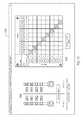
- FIG. 3Ashows an exemplary implantable pulse generator (IPG) of the stimulator system of FIG. 1 .
- IPGimplantable pulse generator
- FIGS. 3B through 3Dshow alternative generalized block diagrams of the IPG of FIG. 3A , wherein the IPG of FIG. 3B has an inductive communications circuit, the IPG of FIG. 3C has a RF transceiver communications circuit, and the IPG of FIG. 3D has an inductive communications circuit and a RF transceiver communications circuit.
- FIG. 4Ashows an exemplary activator of the stimulator system of FIG. 1 .
- FIGS. 4B and 4Cshow alternative generalized block diagrams of the activator of FIG. 4A , wherein the activator of FIG. 4B has an inductive communications circuit and the activator of FIG. 4C has a RF transceiver communications circuit.
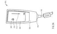
- FIG. 5Ashows an exemplary external programmer of the stimulator system of FIG. 1 .
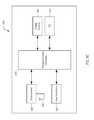
- FIGS. 5B and 5Cshow alternative generalized block diagrams of the external programmer of FIG. 5A , wherein the external programmer of FIG. 5B has an inductive communications circuit and the external programmer of FIG. 5C has a RF transceiver communications circuit.
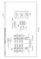
- FIG. 6is a block diagram of the functional components of an exemplary software-based programming system of the stimulator system of FIG. 1 .
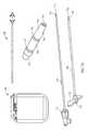
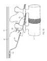
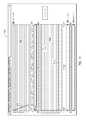
- FIGS. 7A through 7Dshow an exemplary method for implanting an electrode lead and IPG in accordance with the principles of the present invention.
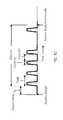
- FIG. 8shows a graph depicting an exemplary charge-balanced electrical stimulation waveform that may be delivered by the electrodes and IPG of the present invention.
- FIG. 9shows a graph depicting an exemplary stimulation pulse train that may be delivered by the electrodes and IPG of the present invention.
- FIG. 10shows a graph depicting an exemplary session that may be delivered by the electrodes and IPG of the present invention.
- FIGS. 11-15are exemplary screenshots illustrating various aspects of the user interface of the software-based programming system of the present invention.
- the neuromuscular stimulation system of the present inventioncomprises implantable devices for facilitating electrical stimulation to tissue within a patient's back and external devices for wirelessly communicating programming data and stimulation commands to the implantable devices.
- the devices disclosed hereinmay be utilized to stimulate tissue associated with local segmental control of the lumbar spine in accordance with the programming data to rehabilitate the tissue over time.
- the stimulator systemmay be optimized for use in treating back pain of the lumbar spine.
- Stimulator system 100includes electrode lead 200 , implantable pulse generator (IPG) 300 , activator 400 , optional magnet 450 , external programmer 500 , and software-based programming system 600 .
- IPGimplantable pulse generator
- Electrode lead 200includes lead body 202 having a plurality of electrodes, illustratively, electrodes 204 , 206 , 208 , and 210 . Electrode lead 200 is configured for implantation in or adjacent to tissue, e.g., nervous tissue, muscle, a ligament, and/or a joint capsule including tissue associated with local segmental control of the lumbar spine. Electrode lead 200 is coupled to IPG 300 , for example, via connector block 302 . IPG 300 is configured to generate pulses such that electrodes 204 , 206 , 208 , and/or 210 deliver neuromuscular electrical stimulation (“NMES”) to target tissue.
- NMESneuromuscular electrical stimulation
- the electrodesare positioned to stimulate a peripheral nerve where the nerve enters skeletal muscle, which may be one or more of the multifidus, transverse abdominus, quadratus lumborum, psoas major, internus abdominus, obliquus externus abdominus, and erector spinae muscles.
- skeletal musclewhich may be one or more of the multifidus, transverse abdominus, quadratus lumborum, psoas major, internus abdominus, obliquus externus abdominus, and erector spinae muscles.
- Such stimulationmay induce contraction of the muscle to restore neural control and rehabilitate the muscle, thereby improving muscle function of local segmental muscles of the lumbar spine, improving lumbar spine stability, and reducing back pain.
- IPG 300is controlled by, and optionally powered by, activator 400 , which includes control module 402 coupled to pad 404 , e.g., via cable 406 .
- Control module 402has user interface 408 that permits a user, e.g., patient, physician, caregiver, to adjust a limited number of operational parameters of IPG 300 including starting and stopping a treatment session.
- Control module 402communicates with IPG 300 via pad 404 , which may comprise an inductive coil or RF transceiver configured to communicate information in a bidirectional manner across a patient's skin to IPG 300 and, optionally, to transmit power to IPG 300 .
- Stimulator system 100also may include optional magnet 450 configured to transmit a magnetic field across a patient's skin to IPG 300 such that a magnetic sensor of IPG 300 senses the magnetic field and IPG 300 starts or stops a treatment session responsive to the sensed magnetic field.
- optional magnet 450configured to transmit a magnetic field across a patient's skin to IPG 300 such that a magnetic sensor of IPG 300 senses the magnetic field and IPG 300 starts or stops a treatment session responsive to the sensed magnetic field.
- software-based programming system 600is installed and runs on a conventional laptop computer, and is used by the patient's physician together with external programmer 500 to provide programming to IPG 300 .
- external programmer 500may be coupled, either wirelessly or using a cable such as cable 502 , to the physician's computer such that software-based programming system 600 may download for review data stored on IPG 300 via external programmer 500 .
- Software-based programming system 600also may transfer programming data to IPG 300 via external programmer 500 to reprogram stimulation parameters programmed into IPG 300 .
- programming system 600may be used to program and adjust parameters such as pulse amplitude (voltage or current), pulse width, stimulation rate, stimulation frequency, ramp timing, cycle timing, session timing, and electrode configuration.
- Programming system 600also may be configured to upload and store data retrieved from IPG 300 to a remote server for later access by the physician.
- Electrode lead 200contains a plurality of electrodes 204 , 206 , 208 , and 210 , disposed at distal end 210 of lead body 202 , that are configured to be implanted in or adjacent to tissue, such as nervous tissue, muscle, ligament, and/or joint capsule.
- Lead body 202is a suitable length for positioning the electrodes in or adjacent to target tissue while IPG is implanted in a suitable location, e.g., the lower back.
- lead body 202may be between about 30 and 80 cm in length, and preferably about 45 or about 65 cm in length.
- Electrodes 204 , 206 , 208 , and 210may be configured to stimulate the tissue at a stimulation frequency and at a level and duration sufficient to cause muscle to contract and may be ring electrodes, partial electrodes, segmented electrodes, nerve cuff electrodes placed around the nerve innervating the target muscle, or the like. Electrodes 204 , 206 , 208 , 210 are a suitable length(s) and spaced apart a suitable distance along lead body 202 .
- electrodes 204 , 206 , 208 , 210may be about 2-5 mm in length, and preferably about 3 mm, and may be spaced apart about 2-6 mm, and preferably about 4 mm.
- an electrode leadmay contain more or fewer than four electrodes.
- first and second fixation elements 212 and 214are coupled to lead body 202 via first and second fixation rings 216 and 218 , respectively.
- First and second fixation elements 212 and 214are configured to sandwich an anchor site, e.g., muscle, therebetween to secure electrode lead 200 at a target site without damaging the anchor site.
- First fixation elements 212are angled distally relative to lead body 202 , and resist motion in the first direction and prevent, in the case illustrated, insertion of the lead too far, as well as migration distally.
- Second fixation elements 214are angled proximally relative to lead body 202 and penetrate through a tissue plane and deploy on the distal side of the tissue immediately adjacent to the target of stimulation.
- First fixation elements 212are configured to resist motion in the opposite direction relative to second fixation elements 214 . This combination prevents migration both proximally and distally, and also in rotation.
- first fixation elements 212are positioned between electrode 208 and distal most electrode 210 and second fixation element 214 is positioned between distal most electrode 210 and end cap 220 .
- the length of and spacing between the fixation elementsis defined by the structure around which they are to be placed. In one embodiment, the length of each fixation element is between about 1.5-4 mm and preferably about 2.5 mm and the spacing is between about 2 mm and 10 mm and preferably about 6 mm.
- First and second fixation elements 212 and 214are configured to collapse inward toward lead body 202 in a delivery state and to expand, e.g., due to retraction of a sheath, in a deployed state. While FIG. 2 illustrates fixation elements 212 and 214 on lead body 202 , it should be understood that other fixation elements may be used to anchor electrode lead 200 at a suitable location including the fixation elements described in U.S. Patent Application Pub. No. 2013/0131766 to Crosby and U.S. patent application Ser. No. 13/797,100, both assigned to the assignee of the present invention, the entire contents of each of which is incorporated herein by reference.
- Lead body 202further includes stylet lumen 222 extending therethrough.
- Stylet lumen 222is shaped and sized to permit a stylet to be inserted therein, for example, during delivery of electrode lead 200 .
- end cap 220is used to prevent the stylet from extending distally out of stylet lumen 222 beyond end cap 220 .
- electrode lead 200includes contacts 226 , 228 , 230 , and 232 separated along lead body 202 by spacers 234 , 236 , 238 , 240 , and 242 .
- Contacts 226 , 228 , 230 , and 232may comprise an isodiametric terminal and are electrically coupled to electrodes 204 , 206 , 208 , and 210 , respectively, via, for example, individually coated spiral wound wires.
- a portion of proximal end 224is configured to be inserted in IPG 300 and set-screw retainer 244 is configured to receive a screw from IPG 300 to secure the portion of electrode lead 200 within IPG 300 .
- the electrode(s)may be an array of a plurality of electrodes, or may be a simple single electrode where the electrical circuit is completed with an electrode placed elsewhere (not shown) such as a skin surface patch or by the can of an implanted pulse generator.
- electrode lead 200may comprise a wirelessly activated or leadless electrode, such as described in U.S. Pat. No. 8,321,021 to Kisker, such that no lead need be coupled to IPG 300 .
- IPG 300is configured to generate pulses for electrical transmission to electrode lead 200 .
- the IPG electronicsare housed in a hermetically sealed metal housing 304 .
- Housing 304may comprise titanium or other biocompatible material, and includes connector block 302 that permits electrode lead 200 to be electrically coupled to the electronics within housing 304 via channel 306 .
- Channel 306is coupled to conductors 308 , 310 , 312 , and 314 which are coupled to the IPG electronics.
- IPG 300When proximal end 224 of electrode lead 200 is inserted within channel 306 , conductors 308 , 310 , 312 , and 314 are electrically coupled to contacts 226 , 228 , 230 , and 232 , respectively, and, in turn, electrically coupled to electrodes 204 , 206 , 208 , and 210 , respectively.
- Set-screw 316is configured to be tightened down on set-screw retainer 244 to secure a portion of electrode lead 200 within channel 306 .
- IPG 300further includes a second channel (not shown) with four additional conductors. The two separate channels facilitate bilateral stimulation and the electrode configuration, e.g., combination of positive and negative electrodes, may be programmed independently for each channel.
- IPG 300is illustratively implantable, a stimulator may be disposed external to a body of a patient on a temporary or permanent basis without departing from the scope of the present invention.
- an external stimulatormay be coupled to the electrodes wirelessly.
- IPG 300may include programmable controller 318 , telemetry system 320 coupled to coil 322 , power supply 324 , electrode switching array 326 , system sensors 328 , and optional therapeutic circuitry module 330 .
- Controller 318is electrically coupled to, and configured to control, the internal functional components of IPG 300 .
- Controller 318may comprise a commercially available microcontroller unit including a programmable microprocessor, volatile memory, nonvolatile memory such as EEPROM for storing programming, and nonvolatile storage, e.g., Flash memory, for storing firmware and a log of system operational parameters and patient data.
- the memory of controller 318stores program instructions that, when executed by the processor of controller 318 , cause the processor and the functional components of IPG 300 to provide the functionality ascribed to them herein.
- Controller 318is configured to be programmable such that programming data is stored in the memory of controller 318 and may be adjusted using external programmer 500 as described below. Programming data may include pulse amplitude (voltage or current), pulse width, stimulation rate, stimulation frequency, ramp timing, cycle timing, session timing, and electrode configuration.
- programmable parameters, their ranges, and nominal valuesare:
- Controller 318may be programmable to allow electrical stimulation between any chosen combination of electrodes on the lead, thus providing a simple bipolar configuration.
- controller 318may be programmed to deliver stimulation pulses in a guarded bipolar configuration (more than 1 anode surrounding a central cathode) or IPG housing 304 may be programmed as the anode, enabling unipolar stimulation from any of the electrodes.
- Controller 318further may be programmed with a routine to calculate the impedance at electrode lead 200 .
- controller 318may direct power supply 324 to send an electrical signal to one or more electrodes which emit electrical power.
- One or more other electrodesreceive the emitted electrical power and send a received signal to controller 318 that runs the routine to calculate impedance based on the sent signal and the received signal.
- Controller 318is coupled to communications circuitry including telemetry system 320 , which is electrically coupled to coil 322 , that permits transmission of stimulation commands, and optionally power, between IPG 300 and activator 400 such that IPG 300 may be powered, programmed, and/or controlled by activator 400 .
- controller 318may start or stop a treatment session responsive to stimulation commands received from a corresponding telemetry system and coil of activator 400 via coil 322 and telemetry system 320 .
- Telemetry system 320 and coil 322further permit transmission of programming data, and optionally power, between IPG 300 and external programmer 500 such that IPG 300 may be powered, programmed, and/or controlled by software-based programming system 600 via external programmer 500 .
- controller 318may direct changes to at least one of pulse amplitude (voltage or current), pulse width, stimulation rate, stimulation frequency, ramp timing, cycle timing, session timing, and electrode configuration responsive to programming data received from a corresponding telemetry system and coil of external programmer 500 via coil 322 and telemetry system 320 .
- telemetry system 320 and coil 322are well known to one skilled in the art and may include a magnet, a short range telemetry system, a longer range telemetry system (such as using MICS RF Telemetry available from Zarlink Semiconductor of Ottawa, Canada), or technology similar to a pacemaker programmer.
- coil 322may be used to transmit power only, and separate radio frequency transmitters may be provided in IPG 300 activator 400 , and/or external programmer 500 for establishing bidirectional or unidirectional data communication.
- Power supply 324powers the electrical components of IPG 300 , and may comprise a primary cell or battery, a secondary (rechargeable) cell or battery or a combination of both. Alternatively, power supply 324 may not include a cell or battery, but instead comprise a capacitor that stores energy transmitted through the skin via a Transcutaneous Energy Transmission System (TETs), e.g., by inductive coupling. In a preferred embodiment, power supply 324 comprises a lithium ion battery.
- TETsTranscutaneous Energy Transmission System
- Controller 318further may be coupled to electrode switching array 326 so that any subset of electrodes of the electrode leads may be selectably coupled to therapeutic circuitry module 330 , described in detail below. In this way, an appropriate electrode set may be chosen from the entire selection of electrodes implanted in the patient's body to achieve a desired therapeutic effect. Electrode switching array 326 preferably operates at high speed, thereby allowing successive stimulation pulses to be applied to different electrode combinations.
- System sensors 328may comprise one or more sensors that monitor operation of the systems of IPG 300 , and log data relating to system operation as well as system faults, which may be stored in a log for later readout using software-based programming system 600 .
- system sensors 328include a magnetic sensor configured to sense a magnetic field and to transmit a signal to controller 318 based on the sensed magnetic field such that the controller starts or stops a treatment session.
- system sensors 328include one or more sensors configured to sense muscle contraction and to generate a sensor signal based on the muscle contraction.
- Controller 318is configured to receive the sensor signal from system sensors 328 and to adjust the stimulation parameters based on the sensor signal.
- system sensors 328sense an increase or decrease in muscle movement and controller 318 increases or decreases the stimulation frequency to maintain smooth and continuous muscle contraction.
- sensors 328may include an accelerometer that senses acceleration of a muscle caused by muscle contraction.
- the accelerometermay be a 1-, 2- or 3-axis analog or digital accelerometer that determines whether the patient is active or asleep or senses overall activity of the patient, which may be a surrogate measure for clinical parameters (e.g., more activity implies less pain), and/or a heart rate or breathing rate (minute ventilation) monitor, e.g., which may be obtained using one or more of the electrodes disposed on the electrode leads.
- the accelerometermay be used to determine the orientation of IPG 300 , and by inference the orientation of the patient, at any time.
- software-based programming system 600may be used to take a reading from the implant, e.g., when the patient is lying prone, to calibrate the orientation of the accelerometer. If the patient is instructed to lie prone during therapy delivery, then the accelerometer may be programmed to record the orientation of the patient during stimulation, thus providing information on patient compliance.
- system sensors 328may include a pressure sensor, a movement sensor, and/or a strain gauge configured to sense muscle contraction and to generate a sensor signal based on the muscle contraction, and in a further embodiment, various combinations of at least one of an accelerometer, a pressure sensor, a movement sensor, and/or a strain gauge are included.
- Sensors 328may also include, for example, a humidity sensor to measure moisture within housing 304 , which may provide information relating to the state of the electronic components, or a temperature sensor, e.g., for measuring battery temperature during charging to ensure safe operation of the battery. Data from the system sensors may be logged by controller 318 and stored in nonvolatile memory for later transmission to software-based programming system 600 via external programmer 500 .
- system sensors 328may be placed in a variety of locations including within housing 302 , within or adjacent to the tissue that is stimulated, and/or in proximity to the muscle to be contracted and connected via a separate lead to IPG 300 .
- sensors 324may be integrated into one or more of the leads used for stimulation or may be an independent sensor(s) operatively coupled to IPG 300 using, for example, radio frequency (RF) signals for transmitting and receiving data.
- RFradio frequency
- Controller 318also may be coupled to optional therapeutic circuitry module 330 that provides any of a number of complimentary therapeutic stimulation, analgesic, feedback or ablation treatment modalities as described in detail below.
- IPG 300illustratively includes one therapeutic circuitry module 330 , although additional circuitry modules may be employed in a particular embodiment depending upon its intended application, as described in U.S. Patent Application Publication No. 2011/0224665 to Crosby, assigned to the assignee of the present invention, the entire contents of which is incorporated herein by reference.
- Therapeutic circuitry module 330may be configured to provide different types of stimulation, either to induce muscle contractions or to block pain signals in afferent nerve fibers; to monitor muscle contractions induced by stimulation and adjust the applied stimulation regime as needed to obtain a desired result; or to selectively and intermittently ablate nerve fibers to control pain and thereby facilitate muscle rehabilitation.
- IPG 300 ′is constructed similarly to IPG 300 of FIG. 3B , wherein like components are identified by like-primed reference numbers.
- power supply 324 ′ in FIG. 3Ccorresponds to power supply 324 of FIG. 3B , etc.
- IPG 300 ′includes a communications circuit employing transceiver 332 coupled to antenna 334 (which may be inside or external to the hermetic housing) rather than telemetry system 320 and coil 322 of IPG 300 .
- Transceiver 332preferably comprises a radio frequency (RF) transceiver and is configured for bi-directional communications via antenna 334 with a similar transceiver circuit disposed in activator 400 and/or external programmer 500 .
- transceiver 332may receive stimulation commands from activator 400 and programming data from software-based programming system 600 via external programmer 500 .
- Controller 318may direct changes to at least one of pulse amplitude (voltage or current), pulse width, stimulation rate, stimulation frequency, ramp timing, cycle timing, session timing, and electrode configuration, including commands to start or stop a treatment session, responsive to programming data and/or stimulation commands received from a corresponding transceiver and antenna of activator 400 and/or external programmer 500 via antenna 334 and transceiver 332 .
- Transceiver 332also may include a low power mode of operation, such that it periodically awakens to listen for incoming messages and responds only to those messages including the unique device identifier assigned to that IPG.
- transceiver 332may employ an encryption routine to ensure that messages sent from, or received by, IPG 300 cannot be intercepted or forged.
- IPG 300 ′′is constructed similarly to IPG 300 of FIG. 3B and IPG 300 ′ of FIG. 3C except that IPG 300 ′′ includes a communications circuit employing telemetry system 320 ′′ and coil 322 ′′ and a communications circuit employing transceiver 332 ′′ and antenna 334 ′′.
- IPG 300 ′′is preferably in an embodiment where IPG 300 ′′ communicates inductively and using RF.
- telemetry system 320 ′′ and coil 322 ′′are configured to transfer stimulation commands, and optionally power, between IPG 300 ′′ and activator 400 from a corresponding telemetry system and coil of activator 400 .
- transceiver 332 ′′ and antenna 334 ′′are configured to transfer programming data between IPG 300 ′′ and external programmer 500 ′ from a corresponding transceiver and antenna of external programmer 500 ′.
- telemetry system 320 ′′ and coil 322 ′′permit transfer of programming data, and optionally power, between IPG 300 ′′ and external programmer 500 from a corresponding telemetry system and coil of external programmer 500 .
- transceiver 332 ′′ and antenna 334 ′′are configured for transfer of stimulation commands between IPG 300 ′′ and activator 400 ′ from a corresponding transceiver and antenna of activator 400 ′.
- Control module 402includes housing 410 sized for handheld use and user interface 408 .
- User interface 408permits a user, e.g., patient, physician, caregiver, to adjust a limited number of operational parameters of IPG 300 including starting and stopping a treatment session.
- user interface 408includes signal LED 412 , status LED 414 , warning LED 416 , start button 418 , stop button 420 , status button 422 , and battery LED 424 .
- Signal LED 412preferably contains multiple diodes, each of which emit light of a different preselected color.
- Signal LED 412is configured to illuminate when the communications circuit within pad 404 detects a suitable connection with a the corresponding communications circuit in IPG 300 suitable for power transmission and/or data communication between IPG 300 and activator 400 .
- signal LED 412illuminates a red diode when there is not a suitable connection, a yellow diode when the connection is suitable but weak, and a green diode when the connection is suitable and strong.
- Status LED 414also may include multiple diodes that illuminate in a pattern of flashes and/or colors to indicate to the user the status of IPG 300 . Such patterns are stored in the memory of the controller of control module 402 and may indicate whether the IPG is directing stimulation to occur or awaiting commands.
- a usermay refer to a user manual to decode a pattern shown on status LED 414 .
- Warning LED 416is configured to illuminate when the controller of control module 402 detects an error and indicates that a user should contact their physician or clinic.
- start button 418the controller of control module 402 directs a signal to be sent to IPG 300 via pad 404 and cable 406 to begin a treatment session.
- stop button 420the controller of control module 402 directs a signal to be sent to IPG 300 via pad 404 and cable 406 to end a treatment session.
- the treatment sessionmay have a predetermined length and the controller de-energizes the electrodes when the session time expires.
- Battery LED 424is configured to illuminate when the controller in control module 402 detects that the battery levels are below a predetermined threshold.
- Pad 404is configured to communicate information and, optionally, transfer power from control module 402 to IPG 300 in a bidirectional manner across a patient's skin.
- pad 404includes an inductive coil within its housing.
- Cable 406is a suitable length so that a patient may comfortably place pad 404 in extracorporeal proximity to IPG 300 implanted in the patient's lower back while viewing control module 402 to confirm correct placement using signal LED 412 .
- Activator 400may include programmable controller 426 , telemetry system 428 coupled to coil 430 , user interface 432 , power supply 434 , and input and output circuitry (I/O) 436 .
- programmable controller 426 , telemetry system 428 , user interface 432 , power supply 434 , and input and output circuitry (I/O) 436are housed within control module housing 410 and coil 430 is housed within the housing for pad 404 .
- Controller 426is electrically coupled to, and configured to control, the internal functional components of activator 400 .
- Controller 426may comprise a commercially available microcontroller unit including a programmable microprocessor, volatile memory, nonvolatile memory such as EEPROM for storing programming, and nonvolatile storage, e.g., Flash memory, for storing firmware and a log of system operational parameters and patient data.
- the memory of controller 426may store program instructions that, when executed by the processor of controller 426 , cause the processor and the functional components of activator 400 to provide the functionality ascribed to them herein.
- Controller 426is configured to be programmable.
- controller 426may send stimulation commands responsive to user input received at user interface 432 to controller 318 of IPG 300 via the telemetry (or RF) systems to start or stop a treatment session.
- a limited number of stimulation parametersmay be adjusted at user interface 432 to minimize the chance of injury caused by adjustments made by non-physician users.
- controller 426also may send adjustments to stimulation parameters, e.g., pulse amplitude (voltage or current), pulse width, stimulation rate, stimulation frequency, ramp timing, cycle timing, session timing, and electrode configuration to IPG 300 responsive to user input received at user interface 432 .
- Controller 426is coupled to telemetry system 428 , which is electrically coupled to coil 430 (e.g., via cable 406 ), that permits transmission of energy and stimulation commands between activator 400 and IPG 300 (or IPG 300 ′′) such that IPG 300 may be powered, programmed, and/or controlled by activator 400 responsive to user input received at user interface 432 .
- controller 426may direct telemetry system 428 and coil 430 to send adjustments to stimulation parameter(s), including commands to start or stop a treatment session or provide status of the IPG, responsive to user input received at user interface 432 to coil 322 and telemetry system 320 of IPG 300 .
- telemetry system 428 and coil 430The technology for telemetry system 428 and coil 430 is well known to one skilled in the art and may be similar to telemetry system 320 and coil 322 described above. Alternatively, coil 430 may be used to transmit power only, and separate radio frequency transmitters may be provided in activator 400 and IPG 300 for establishing bidirectional or unidirectional data communication.
- User interface 432is configured to receive user input and to display information to the user. As described above, user interface 432 may include buttons for receiving user input and LEDs for displaying information to the user. As will be readily apparent to one skilled in the art, user interface 432 is not limited thereto and may use a display, a touch screen, a keypad, a microphone, a speaker, a trackball, or the like.
- Power supply 434powers the electrical components of activator 400 , and may comprise a primary cell or battery, a secondary (rechargeable) cell or battery or a combination of both. Alternatively, power supply 434 may be a port to allow activator 400 to be plugged into a conventional wall socket for powering components.
- I/O 436may include ports for data communication such as wired communication with a computer and/or ports for receiving removable memory, e.g., SD card, upon which program instructions or data related to activator 400 use may be stored.
- removable memorye.g., SD card
- activator 400 ′is constructed similarly to activator 400 of FIG. 4B except that activator 400 ′ includes a communications circuit employing transceiver 438 and antenna 440 rather than a communications circuit employing telemetry system 428 and coil 430 .
- Transceiver 438preferably comprises a radio frequency (RF) transceiver and is configured for bi-directional communications via antenna 440 with transceiver 332 via antenna 334 of IPG 300 ′.
- Transceiver 438may transmit stimulation commands from activator 400 ′ to IPG 300 ′ (or IPG 300 ′′).
- RFradio frequency
- controller 426 ′may direct transceiver 438 to transmit commands to start or stop a treatment session to IPG 300 ′ responsive to user input received at user interface 432 ′.
- controller 426 ′may direct transceiver 438 to transmit a command to provide status of IPG 300 ′ or commands to adjust stimulation parameter(s) to IPG 300 ′ responsive to user input received at user interface 432 ′.
- Transceiver 438also may include a low power mode of operation, such that it periodically awakens to listen for incoming messages and responds only to those messages including the unique device identifier assigned to that activator.
- transceiver 438may employ an encryption routine to ensure that messages sent from, or received by, activator 400 ′ cannot be intercepted or forged.
- External programmer 500includes housing 504 sized for handheld use and user interface 506 .
- User interface 506permits a user, e.g., patient, physician, caregiver, to send programming data to IPG 300 including commands to adjust stimulation parameters.
- user interface 506includes status LED 508 , status button 510 , and signal LEDs 512 .
- Status LED 508is configured to illuminate when status button 510 is pressed to indicate a successful communication has been sent to IPG 300 , e.g., command to stop a treatment session.
- Signal LEDs 512are configured to illuminate based on the strength of the signal between IPG 300 and external programmer 500 .
- the controller of external programmer 500may direct appropriate signal LEDs 512 to illuminate based on the strength of the signals between the respective telemetry systems and coils or transceivers and antennas of external programmer 500 and IPG 300 .
- Signal LEDs 512may include diodes with different colors. For example, signal LEDs 512 may include red diodes configured to illuminate when the signal strength between external programmer 500 and IPG 300 is weak or non-existent, yellow diodes configured to illuminate when the signal strength between external programmer 500 and IPG 300 is medium, and green diodes configured to illuminate when the signal strength between external programmer 500 and IPG 300 is strong.
- External programmer 500further includes port 514 configured to receive cable 502 such that external programmer 500 is electrically coupled and may communicate programming data with software-based programming system 600 run on a computer.
- External programmer 500may include programmable controller 516 , telemetry system 518 coupled to coil 520 , user interface 522 , power supply 524 , and input and output circuitry (I/O) 526 .
- programmable controller 516may include programmable controller 516 , telemetry system 518 coupled to coil 520 , user interface 522 , power supply 524 , and input and output circuitry (I/O) 526 .
- Controller 516is electrically coupled to, and configured to control, the internal functional components of external programmer 500 .
- Controller 516may comprise a commercially available microcontroller unit including a programmable microprocessor, volatile memory, nonvolatile memory such as EEPROM for storing programming, and nonvolatile storage, e.g., Flash memory, for storing firmware and a log of system operational parameters and patient data.
- the memory of controller 516may store program instructions that, when executed by the processor of controller 516 , cause the processor and the functional components of external programmer 500 to provide the functionality ascribed to them herein.
- Controller 516is configured to be programmable such that stimulation parameters, e.g., pulse amplitude (voltage or current), pulse width, stimulation rate, stimulation frequency, ramp timing, cycle timing, session timing, and electrode configuration may be adjusted responsive to user input received at user interface 522 .
- controller 516may send programming data responsive to user input received at user interface 522 to controller 318 of IPG 300 via the respective telemetry (or RF) systems to adjust stimulation parameters or to start or stop a treatment session.
- a physicianhas access to external programmer 500 to minimize the chance of injury caused by adjustments made by non-physician users.
- Controller 516is coupled to telemetry system 518 , which is electrically coupled to coil 520 , that permits transmission of programming data, and optionally power, between software-based programming system 600 and IPG 300 (or IPG 300 ′′) via external programmer 500 .
- IPG 300may be powered, programmed, and/or controlled by software-based programming system 600 and external programmer 500 responsive to user input received at user interface 522 .
- controller 516may direct telemetry system 518 to transmit stimulation parameter(s) such as pulse amplitude (voltage or current), pulse width, stimulation rate, stimulation frequency, ramp timing, cycle timing, session timing, and electrode configuration, including commands to start or stop a treatment session, to IPG 300 responsive to user input received at user interface 522 and/or software-based programming system 600 .
- controller 516may direct telemetry system 518 to transmit interrogation commands such as requests for the actual value of stimulation parameter(s), battery voltage, data logged at IPG 300 , and IPG 300 status data, to IPG 300 responsive to user input received at user interface 522 and/or software-based programming system 600 , and to receive responses to the interrogation commands from IPG 300 .
- controller 516may direct telemetry system 518 to transmit commands to IPG 300 to calculate the impedance of electrode lead 200 using a routine stored on controller 318 of IPG 300 and to receive the calculated lead impedance from the telemetry system of IPG 300 .
- the technology for telemetry system 518 and coil 520is well known to one skilled in the art and may be similar to telemetry system 320 and coil 322 described above.
- coil 520may be used to transmit power only, and separate radio frequency transmitters may be provided in external programmer 500 and IPG 300 for establishing directional data communication.
- User interface 522is configured to receive user input and to display information to the user. As described above, user interface 522 may include buttons for receiving user input and LEDs for displaying information to the user. As will be readily apparent to one skilled in the art, user interface 522 is not limited thereto and may use a display, a touch screen, a keypad, a microphone, a speaker, a trackball, or the like.
- Power supply 524powers the electrical components of external programmer 500 , and may comprise a primary cell or battery, a secondary (rechargeable) cell or battery or a combination of both. Alternatively, power supply 524 may be a port to allow external programmer 524 to be plugged into a conventional wall socket for powering components. In one preferred embodiment, power supply 524 comprises a USB port and cable that enables external programmer 500 to be powered from a computer, e.g., via cable 502 , running software-based programming system 600 .
- I/O 526may include ports for data communication such as wired communication with a computer and/or ports for receiving removable memory, e.g., SD card, upon which program instructions or data related to external programmer 500 use may be stored.
- I/O 526comprises port 514 , and corresponding circuitry, for accepting cable 502 such that external programmer 500 is electrically coupled to a computer running software-based programming system 600 .
- external programmer 500 ′is constructed similarly to external programmer 500 of FIG. 5B except that external programmer 500 ′ includes a communications circuit employing transceiver 528 and antenna 530 rather than a communications circuit employing telemetry system 518 and coil 520 .
- Transceiver 528preferably comprises a radio frequency (RF) transceiver and is configured for bi-directional communications via antenna 530 with transceiver 332 via antenna 334 of IPG 300 ′.
- Transceiver 528may transmit programming data from external programmer 500 ′ to IPG 300 ′ (or IPG 300 ′′).
- RFradio frequency
- controller 516 ′may direct transceiver 528 to transmit stimulation parameter(s) such as pulse amplitude (voltage or current), pulse width, stimulation rate, stimulation frequency, ramp timing, cycle timing, session timing, and electrode configuration, including commands to start or stop a treatment session, to IPG 300 ′ responsive to user input received at user interface 522 ′ and/or software-based programming system 600 .
- stimulation parameter(s)such as pulse amplitude (voltage or current), pulse width, stimulation rate, stimulation frequency, ramp timing, cycle timing, session timing, and electrode configuration, including commands to start or stop a treatment session, to IPG 300 ′ responsive to user input received at user interface 522 ′ and/or software-based programming system 600 .
- controller 516 ′may direct transceiver 528 to transmit interrogation commands such as requests for the actual value of stimulation parameter(s), battery voltage, data logged at IPG 300 ′, and IPG 300 ′ status data, to IPG 300 ′ responsive to user input received at user interface 522 ′ and/or software-based programming system 600 , and to receive responses to the interrogation commands from IPG 300 ′.
- controller 516 ′may direct transceiver 528 to transmit commands to IPG 300 ′ to calculate the impedance of electrode lead 200 using a routine stored on controller 318 ′ of IPG 300 ′ and to receive the calculated lead impedance from transceiver 332 of IPG 300 ′.
- Transceiver 528also may include a low power mode of operation, such that it periodically awakens to listen for incoming messages and responds only to those messages including the unique device identifier assigned to that external programmer.
- transceiver 528may employ an encryption routine to ensure that messages sent from, or received by, external programmer 500 ′ cannot be intercepted or forged.
- the software of programming system 600comprises a number of functional blocks, schematically depicted in FIG. 6 , including main block 602 , event logging block 604 , data download block 606 , configuration setup block 608 , user interface block 610 , alarm detection block 612 , sensor calibration block 614 , firmware upgrade block 616 , device identifier block 618 , and status information block 620 .
- the softwarepreferably is written in C++ and employs an object oriented format.
- the softwareis configured to run on top of a Microsoft WindowsTM (a registered trademark of Microsoft Corporation, Redmond, Wash.) or Unix-based operating system, such as are conventionally employed on desktop and laptop computers.
- the computer running programming system 600preferably includes a data port, e.g., USB port or comparable wireless connection, that permits external programmer 500 and/or activator 400 to be coupled thereto.
- the computermay include a wireless card, e.g., conforming to the IEEE 802.11 standard, thereby enabling IPG 300 , activator 400 , and/or external programmer 500 to communicate wirelessly with the computer running programming system 600 .
- IPG 300 , activator 400 , and/or external programmer 500may include a communications circuit(s) having telephony circuitry, e.g., GSM, CDMA, LTE circuitry, or the like, that automatically dials and uploads data, such as alarm data, from IPG 300 to a secure website accessible by the patient's physician.
- a communications circuit(s) having telephony circuitrye.g., GSM, CDMA, LTE circuitry, or the like, that automatically dials and uploads data, such as alarm data, from IPG 300 to a secure website accessible by the patient's physician.
- Main block 602preferably includes a main software routine that executes on the physician's computer, and controls overall operation of the other functional blocks.
- Main block 602enables the physician to download event data and alarm information stored on IPG 300 , via external programmer 500 , to his office computer, and also permits programming system 600 to directly control operation of IPG 300 , via external programmer 500 .
- Main blockalso enables the physician to upload firmware updates and configuration data to IPG 300 via external programmer 500 .
- Event Log block 604is a record of operational data downloaded from IPG 300 , using external programmer 500 , and may include, for example, treatment session start and stop times, current stimulation parameters, stimulation parameters from previous treatment sessions, sensor data, lead impedance, battery current, battery voltage, battery status, and the like.
- the event logalso may include the occurrence of events, such as alarms or other abnormal conditions.
- Data Download block 606is a routine that commands IPG 300 , using external programmer 500 , to transfer data to programming system 600 for download after IPG 300 is coupled to the computer programming system 600 via external programmer 500 .
- Data Download block 606may initiate, either automatically or at the instigation of the physician via user interface block 610 , downloading of data stored in the event log.
- Configuration Setup block 608is a routine that configures the parameters stored within IPG 300 , using external programmer 500 , that control operation of IPG 300 .
- the interval timing parametersmay determine, e.g., how long the processor remains in sleep mode prior to being awakened to listen for radio communications or to control IPG 300 operation.
- the interval timing parametersmay control, for example, the duration of a treatment session.
- Interval timing settings transmitted to IPG 300 from programming system 600also may determine when and how often event data is written to the memory in controller 318 .
- programming system 600also may be used to configure timing parameters used by the firmware executed by controller 426 of activator 400 .
- Block 608also may be used by the physician to configure parameters stored within the memory of controller 318 relating to limit values on operation of controller 318 . These values may include times when IPG 300 may and may not operate, etc. Block 608 also may configure parameters store within the memory of controller 318 relating to control of operation of IPG 300 . These values may include target numbers of treatment sessions and stimulation parameters.
- User interface block 610handles display of information retrieved from the programming system 600 and IPG 300 , via external programmer 500 , and data download block 606 , and presents that information in an intuitive, easily understood format for physician review. Such information may include status of IPG 300 , treatment session start and stop times, current stimulation parameters, stimulation parameters from previous treatment sessions, sensor data, lead impedance, battery status, and the like. User interface block 610 also generates user interface screens that permit the physician to input information to configure the session timing, stimulation parameters, requests to calculate lead impedance, etc.
- Alarm detection block 612may include a routine for evaluating the data retrieved from IPG 300 , using external programmer 500 , and flagging abnormal conditions for the physician's attention. For example, alarm detection block 612 may flag when a parameter measured by system sensors 328 is above or below a predetermined threshold.
- Sensor calibration block 614may include a routines for testing or measuring drift, of system sensors 328 employed in IPG 300 , e.g., due to aging or change in humidity. Block 614 may then compute offset values for correcting measured data from the sensors, and transmit that information to IPG 300 for storage in the nonvolatile memory of controller 318 .
- Firmware upgrade block 616may comprise a routine for checking the version numbers of the controller firmware installed on IPG 300 , using external programmer 500 , and identify whether upgraded firmware exists. If so, the routine may notify the physician and permit the physician to download revised firmware to IPG 300 , in nonvolatile memory.
- Device identifier block 618consists of a unique identifier for IPG 300 that is stored in the nonvolatile memory of controller 318 and a routine for reading that data when programming system 600 is coupled to IPG 300 via external programmer 500 .
- the device identifieralso may be used by IPG 300 to confirm that wireless communications received from activator 400 and/or external programmer 500 are intended for that specific IPG. Likewise, this information is employed by activator 400 and/or external programmer 500 to determine whether a received message was generated by the IPG associated with that system. Finally, the device identifier information may be employed by programming system 600 to confirm that activator 400 and IPG constitute a matched set.
- Status information block 620comprises a routine for interrogating IPG 300 , when connected via activator 400 , or external programmer 500 and programming system 600 , to retrieve current status data from IPG 300 , using external programmer 500 .
- Such informationmay include, for example, battery status, stimulation parameters, lead impedance, the date and time on the internal clocks of treatment sessions, version control information for the firmware and hardware currently in use, and sensor data.
- FIGS. 7A to 7Dan exemplary method for implanting an electrode lead and IPG is described.
- electrode lead 200 , IPG 300 , stylet (now shown), suture sleeve 700 , introducer 702 , and dilator 704are provided, as shown in FIG. 7A .
- FIG. 7Acomponents of the system are not depicted to scale on either a relative or absolute basis.
- Suture sleeve 700illustratively includes first end section 706 , middle section 708 separated from first end section by first groove 710 , second end section 712 separated from middle section 708 by second groove 714 , and sleeve lumen 716 .
- First and second end sections 706 and 712may have truncated conical portions as shown.
- First and second grooves 710 and 714are sized and shaped to accept sutures such that suture sleeve 700 may be secured to tissue, e.g., superficial fascia, using the sutures.
- Sleeve lumen 716is sized such that electrode lead 200 may be inserted therethrough.
- Introducer 702may include introducer lumen 718 , distal tip 720 , and coupling portion 722 .
- Introducer lumen 718extends through introducer 702 and is shaped and sized to permit electrode lead 200 to slide therethrough.
- Distal tip 720is beveled to ease introduction through tissue.
- Coupling portion 722illustratively a female end with threads, is configured to be coupled to a portion of dilator 704 .
- introducer 702comprises a commercially available 7 French (Fr) introducer.
- Dilator 704may include dilator lumen 724 , distal tip 726 , coupling portion 728 , and handle 730 .
- Dilator lumen 724extends through dilator 704 and is shaped and sized to permit introducer 702 to slide therethrough.
- Distal tip 726is beveled to ease introduction through tissue.
- Coupling portion 728illustratively a male end with threads, is configured to be coupled to a portion of introducer 702 , e.g., coupling portion 722 .
- Handle 730is sized and shaped to permit a physician to comfortably hold dilator 704 .
- a styletis inserted within the stylet lumen of electrode lead 200 to provide additional stiffness to electrode lead 200 to ease passage of electrode lead 200 through introducer 702 .
- the styletmay be a commercially available stylet such as a locking stylet available from Cook Group Incorporated of Bloomington, Ind.
- Electrode lead 200then is inserted within introducer lumen 718 of introducer 702 .
- dilator 704is delivered transcutaneously and transmuscularly to a target site, e.g., in or adjacent to tissue associated with control of the lumbar spine.
- tissuemay include nervous tissue, muscle, ligament, and/or joint capsule.
- muscleincludes skeletal muscle such as the multifidus, transverse abdominus, quadratus lumborum, psoas major, internus abdominus, obliquus externus abdominus, and erector spinae muscles and nervous tissue includes a peripheral nerve that innervates skeletal muscle.
- nervous tissuecomprises the dorsal ramus nerve, or fascicles thereof, that innervate the multifidus muscle.
- introducer 702(having a portion of the electrode lead disposed therein) is inserted through dilator lumen 724 to the target site. Introducer 702 may then be coupled to dilator 704 , e.g., by screwing coupling portion 722 onto coupling portion 728 .
- FIGS. 7B-7Ddepict a lateral projection of a segment of a typical human lumbar spine shown having a vertebral body V, transverse process TP, inter-transverse ligament ITL, and a dorsal ramus DR.
- dilator 704 having introducer 702 disposed therethrough, which has a portion of the electrode lead disposed therein,are positioned adjacent to the target site, illustratively, the medial branch of the dorsal ramus DR nerve that innervates the multifidus muscle.
- electrodes of the electrode leadare positioned to stimulate the medial branch of the dorsal ramus that exits between the L2 and L3 lumbar segments and passes over the transverse process of the L3 vertebra, thereby eliciting contraction of fascicles of the lumbar multifidus at the L3, L4, L5 and S1 segments and in some patients also at the L2 segment.
- Introducer 702 and dilator 704are moved proximally, e.g., using handle 730 , while maintaining the position of electrode lead 200 at the target site, as shown in FIG. 7C .
- the first and second fixation elements of electrode lead 200individually transition from a collapsed state within introducer 702 to an expanded state, shown in FIG. 7C , as introducer 702 passes over the respective fixation element.
- the first and second fixation elementssandwich an anchor site, e.g., muscle, therebetween without damaging the anchor site in the expanded state to fix electrode lead 200 at the target site.
- Introducer 702 and dilator 704are moved proximally off the proximal end of electrode lead 200 and suture sleeve 700 is placed over the proximal end of electrode lead 200 and moved distally, as illustrated in FIG. 7D .
- suture sleeve 700is positioned adjacent to the superficial fascia SF beneath skin SK, sutures are sewn into the first and second grooves of suture sleeve 700 so as to secure suture sleeve 700 to the superficial fascia SF.
- the IPGis coupled to the proximal end of electrode lead 200 and implanted within the lower back of the patient.
- stimulation parametersin accordance with aspects of the present invention are now described.
- such stimulation parametersare selected and programmed to induce contraction of muscle to restore neural control and rehabilitate muscle associated with control of the spine, thereby improving lumbar spine stability and reducing back pain.
- to restore muscle functionmeans to restore an observable degree of muscle function as recognized by existing measures of patient assessment, such as the Oswestry Disability Index (“ODI”) as described in Lauridsen et al., Responsiveness and minimal clinically important difference for pain and disability instruments in low back pain patients , BMC Musculoskeletal Disorders, 7: 82-97 (2006), the European Quality of Life Assessment 5D (“EQ-5D”) as described in Brazier et al., A comparison of the EQ -5 D and SF -6 D across seven patient groups , Health Econ.
- Oswestry Disability Index(“ODI”) as described in Lauridsen et al., Responsiveness and minimal clinically important difference for pain and disability instruments in low back pain patients , BMC Musculoskeletal Disorders, 7: 82-97 (2006)
- EQ-5DEuropean Quality of Life Assessment 5D
- “to restore muscle function”means to observe at least a 15% improvement in one of the foregoing assessment scores within 30-60 days of initiation of treatment.
- the stimulation parametersmay be programmed into the IPG, may be adjusted in the IPG responsive to (i) stimulation commands transferred from the activator or (ii) programming data transferred from the external programmer.
- the stimulation parametersinclude, for example, pulse amplitude (voltage or current), pulse width, stimulation rate, stimulation frequency, ramp timing, cycle timing, session timing, and electrode configuration, including commands to start or stop a treatment session.
- pulse amplitudeis programmed to be adjustable between 0 and 7 mA.
- pulse amplitudeis programmed to be between about 2-5 mA, 2.5-4.5 mA, or 3-4 mA, and preferably about 3.5 mA.
- pulse widthis programmed to be adjustable between 25 and 500 ⁇ s.
- pulse widthis programmed to be between about 100-400 ⁇ s, 150-350 ⁇ s, or 200-300 ⁇ s, and preferably about 350 ⁇ s.
- stimulation rateis programmed to be adjustable between 1 and 40 Hz. In a preferred embodiment, stimulation rate is programmed to be between about 5-35 Hz, 10-30 Hz, or 15-20 Hz, and preferably about 20 Hz. In one embodiment, on ramp timing is programmed to be adjustable between 0 and 5 s. In a preferred embodiment, on ramp timing is programmed to be between about 0.5-4.5 s, 1-4 s, 1.5-3.5 s, or 2-3 s, and preferably about 2.5 s. In one embodiment, off ramp timing is programmed to be adjustable between 0 and 5 s.
- off ramp timingis programmed to be between about 0.5-4.5 s, 1-4 s, 1.5-3.5 s, or 2-3 s, and preferably about 2.5 s.
- cycle-on timingis programmed to be adjustable between 2 and 20 s.
- cycle-on timingis programmed to be between about 4-18 s, 6-16 s, 8-14 s, 9-13 s, or 10-12 s and preferably about 10 s.
- cycle-off timingis programmed to be adjustable between 20 and 120 s.
- cycle-off timingis programmed to be between about 30-110 s, 40-100 s, 50-90 s, 55-85 s, 60-80 s, or 65-75 s and preferably about 70 s.
- session timingis programmed to be adjustable between 1 and 60 min. In a preferred embodiment, session timing is programmed to be between about 5-55 min, 10-50 min, 15-45 min, 20-40 min, or 25-35 min, and preferably about 30 min.
- FIG. 8is a graph of an exemplary charge-balanced electrical stimulation waveform that may be delivered by the electrodes and IPG of the present invention.
- the IPGdirects the electrodes, responsive to programming, stimulation commands, and/or received programming data, to stimulate at a pulse amplitude for the time of a pulse width and then balances the charge by dropping to a negative pulse amplitude and then bringing the pulse amplitude back to zero over the time of a waveform.
- the stimulationmay be current-controlled and charge-balanced, or voltage-controlled and charge-balanced.
- FIG. 9is a graph showing an exemplary stimulation pulse train that may be delivered by the electrodes and IPG of the present invention.
- the IPGdirects the electrodes, responsive to programming, stimulation commands, and/or received programming data, to deliver a stimulation pulse train in an “on ramp” manner such that the pulse amplitude increases in predetermined increments to reach the programmed peak pulse amplitude.
- the number of pulses in the “on ramp” needed to reach the programmed peak pulse amplitudemay be determined by the IPG responsive to data supplied by the programming system.
- the IPGdirects the electrodes to deliver at the programmed peak pulse amplitude for a predetermined number of stimulation pulses.
- the IPGdirects the electrodes, responsive to programming, stimulation commands, and/or received programming data, to deliver a stimulation pulse train in an “off ramp” manner such that the pulse amplitude decreases in predetermined increments from the programmed peak pulse amplitude to zero. As shown in FIG. 9 , the pulse amplitude may drop, e.g., to zero, between each stimulation pulse.
- FIG. 10is a graph showing an exemplary session that may be delivered by the electrodes and IPG of the present invention.
- the IPGdirects the electrodes, responsive to programming, stimulation commands, and/or received programming data, to deliver electrical stimulation for the cycle-on duration, followed by a cycle-off duration of no electrical stimulation.
- a sessionis a programmable duration of repetitive cycles and the session delay is the time delay between the receipt of the command by the IPG to start a session to the start of the first cycle.
- IPGdirects the electrodes, responsive to programming, stimulation commands, and/or received programming data, to stop delivering electrical stimulation until a new session begins.
- FIG. 11shows main program screen 1100 that is displayed to a physician running software-based programming system 600 .
- Main program screen 1100includes identification and status area 1102 , electrode configuration area 1104 , session parameters area 1106 , impedance logging area 1108 , settings area 1110 , and buttons 1112 .
- identification and status area 1102includes Subject ID, IPG Mode, Battery Status, Serial No., and Magnet Effect.
- Subject IDpermits a user, e.g., a physician, to enter an ID, which is then displayed, for a subject having implanted electrodes and an IPG of the present invention.
- IPG Modepermits a user to turn the mode “ON”, such that the IPG implanted in the subject is activated, and turn the mode “OFF”, such that the IPG is deactivated.
- Battery Statusdisplays the remaining battery power of the power supply in the IPG. Battery Status may be updated after a user interrogates the IPG to request updated battery status information.
- Serial No.displays the serial number assigned to the IPG implanted in the subject.
- Magnet Effectpermits a user change how the IPG responds to sensing a magnetic field from a magnet, e.g., magnet 450 .
- a usermay select “Stop Session Only”, such that the IPG will only stop a stimulation session upon sensing the magnet; the user may select “Start Session Only”, such that the IPG will only start a stimulation session upon sensing the magnet; the user may select “Start and Stop Session”, such that the IPG will interchangeably stop or stop a stimulation session each time the magnet is sensed; or the user may select “No Effect”, such that the IPG does not respond to sensing the magnet.
- Electrode configuration area 1104includes Stimulation Mode, Rate, right electrode lead display, left electrode lead display, Amplitude, Pulse Width, Impedance area, and Offset.
- Stimulation Modepermits a user to select a “Bilateral” mode where electrodes on two separate electrode leads stimulate tissue at the same time or a “Unilateral” mode where electrodes on only one electrode lead stimulate tissue.
- Ratepermits a user to select a stimulation rate of any integer between, e.g., 1-40 Hz.
- Right electrode lead displayshows an illustration of four electrodes (numbered 1 - 4 ) on the right electrode lead implanted within the subject while left electrode lead display shows the four electrodes (numbered 5 - 8 ) on the left electrode lead implanted within the subject.
- a usermay select which electrode(s) stimulate in a session and may change the polarity of each electrode between positive and negative.
- negative electrode 2 on the right lead and negative electrode 6 on the left leadtransmit energy to target tissue to stimulate the tissue and positive electrodes 1 and 5 , respectively, receive the energy after it has passed through the target tissue.
- Amplitudepermits a user to adjust the pulse amplitude delivered by an electrode on a lead.
- a usermay increase the pulse amplitude by selecting the Amplitude button and then pressing the corresponding up arrow button and decrease by pressing the corresponding down arrow button for the right or the left electrode lead.
- the pulse amplitudeincreases or decreases by 0.1 mA when the corresponding arrow button is pressed by a user.
- Pulse Widthpermits a user to adjust the pulse width delivered by an electrode on a lead.
- a usermay increase the pulse width by selecting the Pulse Width button and then pressing the corresponding up arrow button and decrease by pressing the corresponding down arrow button for the right or the left electrode lead.
- the pulse widthincreases or decreases by 1 ⁇ s when the corresponding arrow button is pressed by a user.
- a usermay enter in the desired pulse width using, for example, the keyboard on the computer.
- Impedance areapermits a user to select the Measure Impedance button which causes the programming system, via the external programmer, to command the IPG to run the routine to measure impedances and then transmit the measured impedances back to the programming system, via the external programmer.
- the measured impedancesthen are displayed for each electrode. Offset permits a user to offset the stimulation timing between the right and left electrodes.
- Session parameters area 1106includes Session, Cycle On, Cycle Off, On Ramp, and Off Ramp.
- the corresponding button for each of the parameterspermits a user to adjust the timing for each parameter by selecting the button and then pressing the up or down arrows, or, alternatively, by selecting the corresponding button and entering the desired parameter using, for example, the keyboard on the computer.
- Impedance logging area 1108includes Log Impedance Daily, Daily Log Time, Log Impedance Matrix, and Matrix Log Period.
- Log Impedance Dailyincludes a button that permits a user to select “YES” or “NO”. If a user selects “YES”, the IPG will run the impedance test routine every day and store the measured impedance in its memory for transfer to the programming system software.
- Daily Log Timepermits a user to adjust how many hours and minutes per day the IPG will log the measured impedance.
- Log Impedance Matrixpermits a user to select “YES”, where the IPG will store the measured impedance in matrix form, and “NO” where the IPG will not store the measured impedance in matrix form.
- Matrix Log Periodpermits a user to select “Hourly”, “Daily”, or “Weekly”, whereby the IPG will store the measured impedance in a matrix every hour, every day, or every week, respectively.
- Settings area 1110includes Cumulative Max, Lockout Time, Session Delay, Pulse Train Balance, Interphase Period, Balance Mode, Voltage Limit, and Transpose L-R. Cumulative Max permits a user to select the maximum cumulative stimulation session minutes in an amount of days. Lockout Time permits a user to set a number of hours or minutes that a stimulation session may not be initiated. Session Delay permits a user to select a number of seconds that a session will be delayed after IPG receives a command to start a session. Pulse Train Balance permits a user to cause a pulse train balance mode to be “Enabled” or “Disabled”. The pulse train balance mode may be the mode described above with respect to FIG. 9 .
- Interphase Periodpermits a user to adjust the time between stimulation pulses.
- Balance Modepermits a user to cause a balance mode to be “Active” or “Inactive”.
- the balance modemay be the mode described above with respect to FIG. 8 .
- Voltage Limitpermits a user to adjust the maximum voltage that may be supplied from the power source to the electrodes. In one embodiment, Voltage Limit may be set to “Automatic” such that the controller of the IPG determines the maximum voltage based on predetermined thresholds programmed therein.
- Transpose L-Rpermits a user to turn “ON” or “OFF” a mode that, when activated, causes stimulation to be interchanged between the electrodes on the right electrode lead and the electrodes on the left electrode lead.
- Buttons 1112include Interrogate, Program, Start Session, and Stop Session.
- the “Interrogate” buttoncauses the communications circuitry in the external programmer to transmit interrogation commands, such as requests for the (i) actual value of stimulation parameter(s) programmed in the IPG, (ii) battery voltage remaining in the IPG, (iii) data logged in the IPG, and (iv) IPG status data, to the communications circuitry in the IPG for processing by the IPG controller.
- the responsive datais then sent back to the software, via communications circuitry in the IPG and external programmer, for display on the user interface of the computer, such as main program screen 1100 .
- the “Program” buttonwhen pressed, causes the communications circuitry in the external programmer to transmit programming data to the communications circuitry in the IPG for processing by the IPG controller.
- Programming datamay include, for example, adjustments made by the user to the various input areas in main program screen 1100 .
- the “Start Session” buttonwhen pressed, causes the communications circuitry in the external programmer to transmit a command to begin a treatment session, or optionally programming data that includes such a command, to the communications circuitry in the IPG at the selected stimulation parameters for processing by the IPG controller.
- the stimulation parameter datamay be stored in the IPG controller such that future sessions will cause stimulation at the selected stimulation parameters.
- the “Stop Session” buttonwhen pressed, causes the communications circuitry in the external programmer to transmit a command to stop a treatment session to the communications circuitry in the IPG for processing by the IPG controller.
- FIG. 12shows temporary program screen 1200 that is displayed to a physician running software-based programming system 600 .
- Temporary program screen 1200includes electrode configuration area 1202 , session parameters area 1204 , settings area 1206 , and buttons 1208 .
- Temporary program screen 1200permits a user to adjust stimulation parameters on a temporary basis, e.g., for one or two sessions.
- Electrode configuration area 1202is similar to electrode configuration area 1104 of FIG. 11 and for conciseness, will not be described again in detail.
- Session parameters area 1204is similar to session parameters area 1106 of FIG. 11 , although session parameters area 1204 may include fewer parameters for user adjustment.
- session parameters area 1204includes On Ramp and Off Ramp.
- Settings area 1206is similar to settings area 1110 of FIG. 11 , although settings area 1206 may include fewer settings for user adjustment.
- settings area 1206includes Pulse Train Balance, Interphase Period, Balance Mode, Voltage Limit, and Transpose L-R.
- Buttons 1208include Start Temporary Program, Stop Temporary Program, and Copy Changed Values to Main Screen.
- the “Start Temporary Program” buttonwhen pressed, causes the communications circuitry in the external programmer to transmit a command to begin a treatment session to the communications circuitry in the IPG at the selected temporary stimulation parameters for processing by the IPG controller.
- the temporary stimulation parameter datamay be stored in the IPG controller on a temporary basis such that future sessions will cause stimulation at the stimulation parameters programmed prior to receipt of the temporary stimulation parameters.
- the “Stop Temporary Program” buttonwhen pressed, causes the communications circuitry in the external programmer to transmit a command to stop a treatment session to the communications circuitry in the IPG for processing by the IPG controller.
- the “Copy Changed Values to Main Screen” buttonwhen pressed, causes software-based programming system 600 to copy the temporary stimulation parameters entered in screen 1200 into corresponding input areas in main program screen 1100 of FIG. 11 .
- FIG. 13shows impedance screen 1300 that is displayed to a physician running software-based programming system 600 .
- Impedance screen 1300includes electrode configuration area 1302 and impedance matrix area 1304 .
- Electrode configuration area 1302includes right electrode lead impedance display, left electrode lead impedance display, and Impedance area.
- Right electrode lead impedance displayshows an illustration of four electrodes (numbered 5 - 8 ) on the right electrode lead implanted within the subject while left electrode lead impedance display shows the four electrodes (numbered 1 - 4 ) on the left electrode lead implanted within the subject.
- a usermay select at which electrode(s) to measure impedance using the respective displays.
- Impedance areapermits a user to select the “Measure Impedance” button which causes the programming system, via the external programmer, to command the IPG to run the routine to measure impedances at the electrodes selected in the lead displays and then transmit the measured impedances back to the programming system, via the external programmer. The measured impedances then is displayed for each electrode. Selection of electrodes on the lead displays for measuring impedance does not affect electrode configuration area 1104 of main program screen 1100 in FIG. 11 .
- Impedance matrix area 1304includes an impedance matrix and a Measure Impedance Matrix button.
- the “Measure Impedance Matrix” buttoncauses the impedance matrix to be populated with the measured impedances in accordance with selections made at electrode configuration area 1302 .
- impedance between electrode 2 (selected to be negative) and electrode 1 (selected to be positive) on the left leadis measured to be 490 Ohms and impedance between electrode 6 (selected to be negative) and electrode 5 (selected to be positive) on the right electrode lead is measured to be 1355 Ohms.
- the softwarewhen the Measure Impedance Matrix button is pressed, the software causes 490 to be populated at the intersection of 2 negative and 1 positive and 1355 to be populated at the intersection of 6 negative and 5 positive in the impedance matrix.
- the impedance matrixalso may display when an electrode is excluded or out of range.
- FIG. 14shows data review screen 1400 that is displayed to a physician running software-based programming system 600 .
- Data review screen 1400includes daily log area 1402 and data matrix area 1404 .
- Daily log area 1402permits a user to view, on a day-by-day basis, Number of Daily Sessions, Total Daily Session Time, Daily Impedance, and Voltage.
- the date buttonpermits a user to select a day and time such that a user may view stored data from the selected day/time.
- the “Number of Daily Sessions” areadisplays the number of treatment sessions that were started for the selected day.
- the “Total Daily Session Time” areadisplays the number of minutes of treatment sessions for the selected day.
- the “Daily Impedance” areadisplays the measured impedance of the right and left electrode lead for the selected day.
- the “Voltage” areadisplays the measured voltage remaining in the IPG power supply at the end of the selected day.
- Data matrix area 1404includes a data matrix and a “Get Stored Data” button.
- the “Get Stored Data” buttoncauses the communications circuitry in the external programmer to transmit a request for stored data to the communications circuitry in the IPG for processing by the IPG controller.
- the IPG controllerretrieves the stored data from its memory and causes the communications circuitry in the IPG to transmit the stored data to the communications circuitry in the external programmer for display on data review screen 1400 .
- the data matrixis populated with received stored data in the appropriate row and column corresponding to the electrode configuration. The data matrix also may display when an electrode is disabled.
- FIG. 15shows data graphs screen 1500 that is displayed to a physician running software-based programming system 600 .
- Data graphs screen 1500includes session time graph 1502 and impedance graph 1504 .
- Session time graph 1502displays the total daily session time on a daily basis, as retrieved from stored data in the IPG.
- session time 1506shows that the patient used the stimulation system for 60 minutes on the first day and then did not use the stimulation system for the next 15 days.
- Impedance graph 1504displays the daily impedance for the right and left electrode lead on a daily basis, as retrieved from stored data in the IPG.
- right impedance 1508shows that the measured impedance for the electrodes on the right electrode lead was about 12,000 ohms over three days
- left impedance 1510shows that the measured impedance for the electrodes on the left electrode lead was about 1400 ohms over three days.
- the “Get Stored Data” buttoncauses the communications circuitry in the external programmer to transmit a request for stored data to the communications circuitry in the IPG for processing by the IPG controller.
- the IPG controllerretrieves the stored data from its memory and causes the communications circuitry in the IPG to transmit the stored data to the communications circuitry in the external programmer for display on data graphs screen 1500 .
- a usermay enter data into the user interface using suitable mechanisms known in the art, such as, entering numbers, letters, and/or symbols via a keyboard or touch screen, mouse, touchpad, selection from a drop-down menu, voice commands, or the like.
Landscapes
- Health & Medical Sciences (AREA)
- Engineering & Computer Science (AREA)
- Veterinary Medicine (AREA)
- Biomedical Technology (AREA)
- Nuclear Medicine, Radiotherapy & Molecular Imaging (AREA)
- Radiology & Medical Imaging (AREA)
- Life Sciences & Earth Sciences (AREA)
- Animal Behavior & Ethology (AREA)
- General Health & Medical Sciences (AREA)
- Public Health (AREA)
- Neurosurgery (AREA)
- Neurology (AREA)
- Pain & Pain Management (AREA)
- Hospice & Palliative Care (AREA)
- Orthopedic Medicine & Surgery (AREA)
- Heart & Thoracic Surgery (AREA)
- Cardiology (AREA)
- Physics & Mathematics (AREA)
- Physical Education & Sports Medicine (AREA)
- Medicinal Chemistry (AREA)
- Chemical & Material Sciences (AREA)
- Human Computer Interaction (AREA)
- Electromagnetism (AREA)
- Acoustics & Sound (AREA)
- Electrotherapy Devices (AREA)
Abstract
Description
| Parameter | Min | Max | |||
| Amplitude |
| 0 | mA | 7.0 | 1 | ||||
| Pulse Width | |||||||
| 25 | 500 | 200 | |||||
| Rate | |||||||
| 1 | Hz | 40 | Hz | 20 | Hz | ||
| On Ramp | 0 | s | 5 | 2 | s | ||
| Off Ramp | |||||||
| Cycle-On | 2 | s | 20 | s | 10 | s | |
| Cycle-Off | 20 | s | 120 | s | 20 | s | |
| 1 | 60 | 30 | min | ||||
Claims (70)
Priority Applications (20)
| Application Number | Priority Date | Filing Date | Title |
|---|---|---|---|
| US14/792,430US9474906B2 (en) | 2007-03-09 | 2015-07-06 | Systems and methods for restoring muscle function to the lumbar spine |
| US15/202,435US9950159B2 (en) | 2013-10-23 | 2016-07-05 | Systems and methods for restoring muscle function to the lumbar spine and kits for implanting the same |
| US15/299,399US10016603B2 (en) | 2007-03-09 | 2016-10-20 | Systems and methods for restoring muscle function to the lumbar spine |
| US15/944,730US10828490B2 (en) | 2007-03-09 | 2018-04-03 | Systems and methods for restoring muscle function to the lumbar spine |
| US15/948,945US10449355B2 (en) | 2012-06-13 | 2018-04-09 | Systems and methods for restoring muscle function to the lumbar spine and kits for implanting the same |
| US16/264,632US11103706B2 (en) | 2007-03-09 | 2019-01-31 | Systems and methods for enhancing function of spine stabilization muscles associated with a spine surgery intervention |
| US16/656,500US11376427B2 (en) | 2012-06-13 | 2019-10-17 | Systems and methods for restoring muscle function to the lumbar spine and kits for implanting the same |
| US17/092,073US11951310B2 (en) | 2007-03-09 | 2020-11-06 | Systems and methods for restoring muscle function to the lumbar spine |
| US17/411,713US11331488B2 (en) | 2007-03-09 | 2021-08-25 | Systems and methods for enhancing function of spine stabilization muscles associated with a spine surgery intervention |
| US17/660,375US11679261B2 (en) | 2007-03-09 | 2022-04-22 | Systems and methods for enhancing function of spine stabilization muscles associated with a spine surgery intervention |
| US17/810,586US11786725B2 (en) | 2012-06-13 | 2022-07-01 | Systems and methods for restoring muscle function to the lumbar spine and kits for implanting the same |
| US17/812,989US11679262B2 (en) | 2007-03-09 | 2022-07-15 | Systems and methods for restoring muscle function to the lumbar spine |
| US18/046,835US12097365B2 (en) | 2010-03-11 | 2022-10-14 | Electrical stimulator for the treatment of back pain and methods of use |
| US18/333,486US12121728B2 (en) | 2007-03-09 | 2023-06-12 | Systems and methods for enhancing function of spine stabilization muscles associated with a spine surgery intervention |
| US18/333,474US12168130B2 (en) | 2007-03-09 | 2023-06-12 | Systems and methods for restoring muscle function to the lumbar spine |
| US18/614,512US20240341808A1 (en) | 2012-06-13 | 2024-03-22 | Systems and methods for enhanced implantation of electrode leads between tissue layers |
| US18/884,063US20250001164A1 (en) | 2010-03-11 | 2024-09-12 | Electrical stimulator for the treatment of back pain and methods of use |
| US18/920,703US20250041602A1 (en) | 2007-03-09 | 2024-10-18 | Systems and methods for enhancing function of spine stabilization muscles associated with a spine surgery intervention |
| US18/980,413US12285612B1 (en) | 2007-03-09 | 2024-12-13 | Systems and methods for restoring muscle function to the lumbar spine |
| US19/188,645US20250249252A1 (en) | 2007-03-09 | 2025-04-24 | Systems and methods for restoring muscle function to the lumbar spine |
Applications Claiming Priority (5)
| Application Number | Priority Date | Filing Date | Title |
|---|---|---|---|
| US90597907P | 2007-03-09 | 2007-03-09 | |
| US12/075,174US8428728B2 (en) | 2007-03-09 | 2008-03-10 | Muscle stimulator |
| US13/858,809US8606358B2 (en) | 2007-03-09 | 2013-04-08 | Muscle stimulator |
| US14/061,614US9072897B2 (en) | 2007-03-09 | 2013-10-23 | Systems and methods for restoring muscle function to the lumbar spine |
| US14/792,430US9474906B2 (en) | 2007-03-09 | 2015-07-06 | Systems and methods for restoring muscle function to the lumbar spine |
Related Parent Applications (2)
| Application Number | Title | Priority Date | Filing Date |
|---|---|---|---|
| US14/061,614ContinuationUS9072897B2 (en) | 2007-03-09 | 2013-10-23 | Systems and methods for restoring muscle function to the lumbar spine |
| US15/948,945ContinuationUS10449355B2 (en) | 2010-03-11 | 2018-04-09 | Systems and methods for restoring muscle function to the lumbar spine and kits for implanting the same |
Related Child Applications (2)
| Application Number | Title | Priority Date | Filing Date |
|---|---|---|---|
| US15/202,435Continuation-In-PartUS9950159B2 (en) | 2010-03-11 | 2016-07-05 | Systems and methods for restoring muscle function to the lumbar spine and kits for implanting the same |
| US15/299,399ContinuationUS10016603B2 (en) | 2007-03-09 | 2016-10-20 | Systems and methods for restoring muscle function to the lumbar spine |
Publications (2)
| Publication Number | Publication Date |
|---|---|
| US20150306405A1 US20150306405A1 (en) | 2015-10-29 |
| US9474906B2true US9474906B2 (en) | 2016-10-25 |
Family
ID=50066762
Family Applications (5)
| Application Number | Title | Priority Date | Filing Date |
|---|---|---|---|
| US14/061,614ActiveUS9072897B2 (en) | 2007-03-09 | 2013-10-23 | Systems and methods for restoring muscle function to the lumbar spine |
| US14/792,430ActiveUS9474906B2 (en) | 2007-03-09 | 2015-07-06 | Systems and methods for restoring muscle function to the lumbar spine |
| US15/299,399ActiveUS10016603B2 (en) | 2007-03-09 | 2016-10-20 | Systems and methods for restoring muscle function to the lumbar spine |
| US15/944,730ActiveUS10828490B2 (en) | 2007-03-09 | 2018-04-03 | Systems and methods for restoring muscle function to the lumbar spine |
| US17/092,073Active2030-03-21US11951310B2 (en) | 2007-03-09 | 2020-11-06 | Systems and methods for restoring muscle function to the lumbar spine |
Family Applications Before (1)
| Application Number | Title | Priority Date | Filing Date |
|---|---|---|---|
| US14/061,614ActiveUS9072897B2 (en) | 2007-03-09 | 2013-10-23 | Systems and methods for restoring muscle function to the lumbar spine |
Family Applications After (3)
| Application Number | Title | Priority Date | Filing Date |
|---|---|---|---|
| US15/299,399ActiveUS10016603B2 (en) | 2007-03-09 | 2016-10-20 | Systems and methods for restoring muscle function to the lumbar spine |
| US15/944,730ActiveUS10828490B2 (en) | 2007-03-09 | 2018-04-03 | Systems and methods for restoring muscle function to the lumbar spine |
| US17/092,073Active2030-03-21US11951310B2 (en) | 2007-03-09 | 2020-11-06 | Systems and methods for restoring muscle function to the lumbar spine |
Country Status (1)
| Country | Link |
|---|---|
| US (5) | US9072897B2 (en) |
Cited By (25)
| Publication number | Priority date | Publication date | Assignee | Title |
|---|---|---|---|---|
| US9724151B2 (en) | 2013-08-08 | 2017-08-08 | Relievant Medsystems, Inc. | Modulating nerves within bone using bone fasteners |
| US9775627B2 (en) | 2012-11-05 | 2017-10-03 | Relievant Medsystems, Inc. | Systems and methods for creating curved paths through bone and modulating nerves within the bone |
| US10028753B2 (en) | 2008-09-26 | 2018-07-24 | Relievant Medsystems, Inc. | Spine treatment kits |
| US10111704B2 (en) | 2002-09-30 | 2018-10-30 | Relievant Medsystems, Inc. | Intraosseous nerve treatment |
| US10265099B2 (en) | 2008-09-26 | 2019-04-23 | Relievant Medsystems, Inc. | Systems for accessing nerves within bone |
| US10390877B2 (en) | 2011-12-30 | 2019-08-27 | Relievant Medsystems, Inc. | Systems and methods for treating back pain |
| US10463423B2 (en) | 2003-03-28 | 2019-11-05 | Relievant Medsystems, Inc. | Thermal denervation devices and methods |
| US10569083B2 (en) | 2010-11-11 | 2020-02-25 | IINN, Inc. | Motor devices for motor nerve root stimulation |
| US10588691B2 (en) | 2012-09-12 | 2020-03-17 | Relievant Medsystems, Inc. | Radiofrequency ablation of tissue within a vertebral body |
| USRE48460E1 (en) | 2002-09-30 | 2021-03-09 | Relievant Medsystems, Inc. | Method of treating an intraosseous nerve |
| US11007010B2 (en) | 2019-09-12 | 2021-05-18 | Relevant Medsysterns, Inc. | Curved bone access systems |
| US11331488B2 (en) | 2007-03-09 | 2022-05-17 | Mainstay Medical Limited | Systems and methods for enhancing function of spine stabilization muscles associated with a spine surgery intervention |
| US11471670B2 (en) | 2010-03-11 | 2022-10-18 | Mainstay Medical Limited | Electrical stimulator for treatment of back pain and methods of use |
| US11672969B2 (en) | 2012-12-07 | 2023-06-13 | Medtronic, Inc. | Minimally invasive implantable neurostimulation system |
| US11679261B2 (en) | 2007-03-09 | 2023-06-20 | Mainstay Medical Limited | Systems and methods for enhancing function of spine stabilization muscles associated with a spine surgery intervention |
| US11679262B2 (en) | 2007-03-09 | 2023-06-20 | Mainstay Medical Limited | Systems and methods for restoring muscle function to the lumbar spine |
| US11684774B2 (en) | 2010-03-11 | 2023-06-27 | Mainstay Medical Limited | Electrical stimulator for treatment of back pain and methods of use |
| US11786725B2 (en) | 2012-06-13 | 2023-10-17 | Mainstay Medical Limited | Systems and methods for restoring muscle function to the lumbar spine and kits for implanting the same |
| US11813454B2 (en) | 2010-11-11 | 2023-11-14 | IINN, Inc. | Methods of bypassing neurological damage through motor nerve root stimulation |
| US11937847B2 (en) | 2016-07-05 | 2024-03-26 | Mainstay Medical Limited | Systems and methods for enhanced implantation of electrode leads between tissue layers |
| US11951310B2 (en) | 2007-03-09 | 2024-04-09 | Mainstay Medical Limited | Systems and methods for restoring muscle function to the lumbar spine |
| US12039731B2 (en) | 2020-12-22 | 2024-07-16 | Relievant Medsystems, Inc. | Prediction of candidates for spinal neuromodulation |
| US12082876B1 (en) | 2020-09-28 | 2024-09-10 | Relievant Medsystems, Inc. | Introducer drill |
| US12097365B2 (en) | 2010-03-11 | 2024-09-24 | Mainstay Medical Limited | Electrical stimulator for the treatment of back pain and methods of use |
| US12433668B1 (en) | 2021-11-08 | 2025-10-07 | Relievant Medsystems, Inc. | Impedance stoppage mitigation during radiofrequency tissue ablation procedures |
Families Citing this family (37)
| Publication number | Priority date | Publication date | Assignee | Title |
|---|---|---|---|---|
| US10925637B2 (en)* | 2010-03-11 | 2021-02-23 | Mainstay Medical Limited | Methods of implanting electrode leads for use with implantable neuromuscular electrical stimulator |
| WO2008112178A1 (en) | 2007-03-09 | 2008-09-18 | Dan Sachs | Muscle stimulator |
| US9999763B2 (en) | 2012-06-13 | 2018-06-19 | Mainstay Medical Limited | Apparatus and methods for anchoring electrode leads adjacent to nervous tissue |
| US9950159B2 (en) | 2013-10-23 | 2018-04-24 | Mainstay Medical Limited | Systems and methods for restoring muscle function to the lumbar spine and kits for implanting the same |
| US11413458B2 (en) | 2011-05-19 | 2022-08-16 | Neuros Medical, Inc. | Nerve cuff electrode for neuromodulation in large human nerve trunks |
| US9079019B2 (en) | 2011-08-02 | 2015-07-14 | Mainstay Medical Limited | Apparatus and methods for anchoring electrode leads for use with implantable neuromuscular electrical stimulator |
| US10195419B2 (en) | 2012-06-13 | 2019-02-05 | Mainstay Medical Limited | Electrode leads for use with implantable neuromuscular electrical stimulator |
| US9186501B2 (en) | 2012-06-13 | 2015-11-17 | Mainstay Medical Limited | Systems and methods for implanting electrode leads for use with implantable neuromuscular electrical stimulator |
| US9174053B2 (en) | 2013-03-08 | 2015-11-03 | Boston Scientific Neuromodulation Corporation | Neuromodulation using modulated pulse train |
| CN106456974B (en)* | 2014-06-03 | 2019-03-12 | 梅恩斯塔伊医疗公司 | System for implanting electrode leads for use with implantable neuromuscular electrical stimulators |
| US10471268B2 (en) | 2014-10-16 | 2019-11-12 | Mainstay Medical Limited | Systems and methods for monitoring muscle rehabilitation |
| AU2016251663B2 (en)* | 2015-04-22 | 2018-10-04 | Boston Scientific Neuromodulation Corporation | Systems for programming neuromodulation devices |
| US9827422B2 (en)* | 2015-05-28 | 2017-11-28 | Boston Scientific Neuromodulation Corporation | Neuromodulation using stochastically-modulated stimulation parameters |
| US10052490B2 (en) | 2015-06-09 | 2018-08-21 | Nuvectra Corporation | Systems, methods, and devices for performing electronically controlled test stimulation |
| US9669227B2 (en) | 2015-06-09 | 2017-06-06 | Nuvectra Corporation | Systems, methods, and devices for generating arbitrary stimulation waveforms |
| US10076667B2 (en) | 2015-06-09 | 2018-09-18 | Nuvectra Corporation | System and method of performing computer assisted stimulation programming (CASP) with a non-zero starting value customized to a patient |
| US9872988B2 (en) | 2015-06-09 | 2018-01-23 | Nuvectra Corporation | Systems, methods, and devices for evaluating lead placement based on patient physiological responses |
| US9750946B2 (en) | 2015-06-09 | 2017-09-05 | Nuvectra Corporation | Systems, methods, and devices for evaluating lead placement based on generated visual representations of sacrum and lead |
| AU2017210296B2 (en) | 2016-01-19 | 2021-05-13 | Incube Labs, Llc | Systems and methods for patient-enabled bladder control |
| WO2017139784A1 (en)* | 2016-02-12 | 2017-08-17 | Axonics Modulation Technologies, Inc. | External pulse generator device and associated methods for trial nerve stimulation |
| WO2017165410A1 (en) | 2016-03-21 | 2017-09-28 | Nalu Medical, Inc. | Devices and methods for positioning external devices in relation to implanted devices |
| WO2018007913A1 (en)* | 2016-07-05 | 2018-01-11 | Mainstay Medical Limited | Systems and methods for restoring muscle function to the lumbar spine and kits for implanting same |
| EP3484577B1 (en) | 2016-07-18 | 2025-06-18 | Nalu Medical, Inc. | Systems for treating pelvic disorders and pain conditions |
| US10551282B2 (en)* | 2017-02-13 | 2020-02-04 | City University Of Hong Kong | Apparatus and method for testing performance of an electrosurgical tool |
| WO2018156953A1 (en) | 2017-02-24 | 2018-08-30 | Nalu Medical, Inc. | Apparatus with sequentially implanted stimulators |
| US10117580B1 (en) | 2017-05-06 | 2018-11-06 | Synerfuse, Inc. | Systems, devices and methods that affect neural tissue through the delivery of a pulsed radio frequency signal generated by an implantable medical device |
| AU2018265016B2 (en) | 2017-05-09 | 2023-01-05 | Nalu Medical, Inc. | Stimulation apparatus |
| US11458309B2 (en)* | 2017-09-19 | 2022-10-04 | United States Government As Represented By The Department Of Veterans Affairs | Flexible implantable tissue stimulator and methods of making and using same |
| EP3723840B1 (en) | 2017-12-13 | 2022-11-30 | Neuros Medical, Inc. | Nerve cuff deployment devices |
| EP3773876B1 (en)* | 2018-04-09 | 2024-04-17 | Neuros Medical, Inc. | Apparatuses for setting an electrical dose |
| CN113613713B (en) | 2019-03-06 | 2024-07-19 | 浙江迈达佩思医疗科技有限公司 | Devices, systems and methods for delivering therapy to intestinal muscles |
| US12017073B2 (en) | 2019-05-16 | 2024-06-25 | Enteromed Ltd | Devices, systems, and methods for delivering therapy to a sacral nerve |
| AU2021219722A1 (en) | 2020-02-11 | 2022-09-08 | Neuros Medical, Inc. | System and method for quantifying qualitative patient-reported data sets |
| US12397162B2 (en) | 2020-12-15 | 2025-08-26 | Boston Scientific Neuromodulation Corporation | Method and apparatus for generating modulated neurostimulation pulse sequence |
| CA3211853A1 (en) | 2021-03-12 | 2022-09-15 | Amber Therapeutics Ltd | Systems for incontinence control |
| WO2022226370A1 (en)* | 2021-04-23 | 2022-10-27 | CyMedica Orthopedics, Inc. | Unique therapeutic dose for nmes systems |
| WO2025029752A2 (en)* | 2023-07-28 | 2025-02-06 | Gate Science, Inc. | Methods and systems for pain management and testing thereof |
Citations (218)
| Publication number | Priority date | Publication date | Assignee | Title |
|---|---|---|---|---|
| US3077884A (en) | 1957-06-13 | 1963-02-19 | Batrow Lab Inc | Electro-physiotherapy apparatus |
| US3710777A (en) | 1970-12-23 | 1973-01-16 | C Sparks | Method and apparatus for growing graft tubes in place |
| US3875947A (en) | 1974-02-19 | 1975-04-08 | James L Jula | Device for screwing body tissue electrode into body tissue |
| US3893463A (en) | 1973-12-07 | 1975-07-08 | Medtronic Inc | Dual channel stimulator |
| US3999551A (en) | 1975-01-07 | 1976-12-28 | Bio-Medical Research, Ltd. | Subcutaneous guide assembly |
| US4010757A (en) | 1974-02-19 | 1977-03-08 | Jula James L | Auxiliary tool for removing electrode from holder |
| US4026301A (en) | 1975-04-21 | 1977-05-31 | Medtronic, Inc. | Apparatus and method for optimum electrode placement in the treatment of disease syndromes such as spinal curvature |
| US4342317A (en) | 1980-04-01 | 1982-08-03 | The Professional Staff Association Of The Rancho Los Amigos Hospital, Inc. | Method of electrical muscle stimulation for treatment of scoliosis and other spinal deformities |
| US4408609A (en) | 1980-04-01 | 1983-10-11 | Professional Staff Association Of The Rancho Los Amigos Hospital, Inc. | Electrical muscle stimulation for treatment of scoliosis and other spinal deformities |
| US4418693A (en) | 1980-12-10 | 1983-12-06 | Leveen Eric G | Vein and tubing passer surgical instrument |
| US4549556A (en) | 1982-12-08 | 1985-10-29 | Cordis Corporation | Implantable lead |
| US4574806A (en) | 1984-10-01 | 1986-03-11 | Cordis Corporation | Tunnelling device for peripheral vascular reconstruction |
| US4658835A (en) | 1985-07-25 | 1987-04-21 | Cordis Corporation | Neural stimulating lead with fixation canopy formation |
| US4832687A (en) | 1987-12-31 | 1989-05-23 | Smith Iii Ray C | Subcutaneous tunneling instrument and method |
| US4917093A (en) | 1987-06-12 | 1990-04-17 | Minnesota Mining And Manufacturing Company | Biological tissue stimulator with adjustable high voltage power supply dependent upon load impedance |
| US5069680A (en) | 1989-12-06 | 1991-12-03 | Medtronic, Inc. | Muscle stimulator with variable duty cycle |
| US5199430A (en) | 1991-03-11 | 1993-04-06 | Case Western Reserve University | Micturitional assist device |
| US5215088A (en) | 1989-11-07 | 1993-06-01 | The University Of Utah | Three-dimensional electrode device |
| US5300108A (en) | 1993-01-05 | 1994-04-05 | Telectronics Pacing Systems, Inc. | Active fixation lead with a dual-pitch, free spinning compound screw |
| US5330515A (en) | 1992-06-17 | 1994-07-19 | Cyberonics, Inc. | Treatment of pain by vagal afferent stimulation |
| US5496345A (en) | 1992-06-02 | 1996-03-05 | General Surgical Innovations, Inc. | Expansible tunneling apparatus for creating an anatomic working space |
| US5501452A (en) | 1994-06-24 | 1996-03-26 | Halvorson; Glen A. | Putting training device using muscle memory |
| US5507788A (en) | 1994-08-11 | 1996-04-16 | The Regents Of The University Of California | Method and apparatus for controlling skeletal muscle fatigue during electrical stimulation |
| US5522854A (en) | 1994-05-19 | 1996-06-04 | Duke University | Method and apparatus for the prevention of arrhythmia by nerve stimulation |
| US5569183A (en) | 1994-06-01 | 1996-10-29 | Archimedes Surgical, Inc. | Method for performing surgery around a viewing space in the interior of the body |
| US5638825A (en) | 1994-04-21 | 1997-06-17 | Nec Corporation | Evoked potential measuring apparatus |
| US5733307A (en) | 1996-09-17 | 1998-03-31 | Amei Technologies, Inc. | Bone anchor having a suture trough |
| US5741321A (en) | 1996-01-11 | 1998-04-21 | Medtronic, Inc. | Active fixation medical electrical lead having improved turning tool |
| US5782841A (en) | 1993-08-10 | 1998-07-21 | Medtronic, Inc. | Tunneling tool for subcutaneous lead placement |
| US5807234A (en) | 1997-06-27 | 1998-09-15 | Pacesetter, Inc. | Myostimulator control using metabolic demand and muscle performance |
| EP0587269B1 (en) | 1992-09-09 | 1998-12-16 | Telectronics N.V. | A multiple channel cardiosynchronous myoplasty apparatus |
| US5873900A (en) | 1995-09-13 | 1999-02-23 | Empi, Inc. | Electronic pain feedback system and method |
| US5916172A (en) | 1995-03-29 | 1999-06-29 | The University Of Queensland | Diagnosis of neuromuscular dysfunction |
| US5957968A (en) | 1997-09-26 | 1999-09-28 | Medtronic, Inc. | Suture sleeve with lead locking device |
| US6104957A (en) | 1998-08-21 | 2000-08-15 | Alo; Kenneth M. | Epidural nerve root stimulation with lead placement method |
| US6119516A (en) | 1997-05-23 | 2000-09-19 | Advantedge Systems, Inc. | Biofeedback system for monitoring the motion of body joint |
| US6314325B1 (en) | 1998-04-07 | 2001-11-06 | William R. Fitz | Nerve hyperpolarization method and apparatus for pain relief |
| US6319241B1 (en) | 1998-04-30 | 2001-11-20 | Medtronic, Inc. | Techniques for positioning therapy delivery elements within a spinal cord or a brain |
| US6324414B1 (en) | 1999-05-18 | 2001-11-27 | Depuy Orthopaedics, Inc. | Tunneling lead terminal having a disposal sheath |
| US6366819B1 (en) | 2000-10-03 | 2002-04-02 | Medtronic, Inc. | Biostable small French lead |
| US20020065543A1 (en) | 2000-11-29 | 2002-05-30 | Pacesetter, Inc. | Double threaded stylet for extraction of leads with a threaded electrode |
| US6406421B1 (en) | 1998-09-08 | 2002-06-18 | Medtronic, Inc. | System and method of determining skeletal muscle contraction by serial lead impedance measurements |
| US20020099419A1 (en) | 2001-01-25 | 2002-07-25 | Biocontrol Medical Bcm Ltd. | Method and apparatus for selective control of nerve fibers |
| US20020115945A1 (en) | 2001-01-11 | 2002-08-22 | Herman Richard M. | Method for restoring gait in individuals with chronic spinal cord injury |
| US20020156513A1 (en) | 2000-08-17 | 2002-10-24 | Borkan William N. | Spinal cord stimulation leads |
| US6473654B1 (en) | 2000-03-08 | 2002-10-29 | Advanced Bionics Corporation | Lead anchor |
| US20020161415A1 (en) | 2001-04-26 | 2002-10-31 | Ehud Cohen | Actuation and control of limbs through motor nerve stimulation |
| US20020183765A1 (en) | 1998-05-26 | 2002-12-05 | Scimed Life Systems, Inc. | Implantable tissue fastener and system for treating gastroesophageal reflux disease |
| US6516227B1 (en) | 1999-07-27 | 2003-02-04 | Advanced Bionics Corporation | Rechargeable spinal cord stimulator system |
| US6527787B1 (en) | 1995-05-19 | 2003-03-04 | General Surgical Innovations, Inc. | Methods and devices for blood vessel harvesting |
| US6565594B1 (en) | 1997-09-24 | 2003-05-20 | Atrium Medical Corporation | Tunneling device |
| US20030100933A1 (en) | 2001-04-26 | 2003-05-29 | Biocontrol Medical Ltd. | Nerve stimulation for treating spasticity, tremor, muscle weakness, and other motor disorders |
| US20030120328A1 (en) | 2001-12-21 | 2003-06-26 | Transneuronix, Inc. | Medical implant device for electrostimulation using discrete micro-electrodes |
| US6600956B2 (en) | 2001-08-21 | 2003-07-29 | Cyberonics, Inc. | Circumneural electrode assembly |
| US6605094B1 (en) | 1999-11-19 | 2003-08-12 | Advanced Bionics Corporation | Integrated subcutaneous tunneling and carrying tool |
| US20030199938A1 (en) | 2002-04-22 | 2003-10-23 | Karel Smits | Precise cardiac lead placement based on impedance measurements |
| US6671557B1 (en) | 2000-10-10 | 2003-12-30 | Meagan Medical, Inc. | System and method for providing percutaneous electrical therapy |
| US20040030360A1 (en) | 2000-08-31 | 2004-02-12 | Meir Eini | Intravaginal device for electrically stimulating and/or for sensing electrical activity of muscles and or nerves defining and surrounding the intravaginal cavity |
| US6735474B1 (en) | 1998-07-06 | 2004-05-11 | Advanced Bionics Corporation | Implantable stimulator system and method for treatment of incontinence and pain |
| US20040111118A1 (en) | 2000-09-26 | 2004-06-10 | Hill Michael R.S. | Method and system for spinal cord stimulation prior to and during a medical procedure |
| US20040122482A1 (en) | 2002-12-20 | 2004-06-24 | James Tung | Nerve proximity method and device |
| US20040147969A1 (en) | 2000-01-11 | 2004-07-29 | Brian Mann | System for detecting, diagnosing, and treating cardiovascular disease |
| WO2004066820A2 (en) | 2003-01-24 | 2004-08-12 | Northstar Neuroscience Inc. | Systems and methods for reducing the likelihood of inducing collateral neural activity during neural stimulation threshold test procedures |
| US20040214790A1 (en) | 2002-12-30 | 2004-10-28 | Purdue Research Foundation | Method of treatment for central nervous system injury |
| US20040230281A1 (en) | 2003-04-11 | 2004-11-18 | Ron Heil | Expandable fixation elements for subcutaneous electrodes |
| US20040236383A1 (en) | 2003-05-23 | 2004-11-25 | Yelizarov Nikolay I. | MONES for muscle strain, repetitive strain injuries and related health conditions |
| US6845271B2 (en) | 1998-06-03 | 2005-01-18 | Neurocontrol Corporation | Treatment of shoulder dysfunction using a percutaneous intramuscular stimulation system |
| US6862479B1 (en) | 2000-08-30 | 2005-03-01 | Advanced Bionics Corporation | Spinal cord stimulation as a therapy for sexual dysfunction |
| US20050075701A1 (en) | 2003-10-01 | 2005-04-07 | Medtronic, Inc. | Device and method for attenuating an immune response |
| US20050080472A1 (en) | 2003-10-10 | 2005-04-14 | Atkinson Robert Emmett | Lead stabilization devices and methods |
| US20050119713A1 (en) | 2000-08-18 | 2005-06-02 | Whitehurst Todd K. | Methods for implanting a spinal cord stimulator |
| US20050149154A1 (en) | 2003-12-29 | 2005-07-07 | Biocontrol Medical Bcm Ltd. | Nerve-branch-specific action-potential activation,inhibition, and monitoring |
| US20050154389A1 (en) | 2003-12-16 | 2005-07-14 | Depuy Spine, Inc. | Methods and devices for minimally invasive spinal fixation element placement |
| CN1211930C (en) | 2001-12-27 | 2005-07-20 | 卓联半导体股份有限公司 | Method of stabilizing phase-locked loop |
| US20050165456A1 (en) | 2003-12-19 | 2005-07-28 | Brian Mann | Digital electrode for cardiac rhythm management |
| US20050177211A1 (en) | 2002-03-05 | 2005-08-11 | Baylis Medical Company Inc. | Electrosurgical device for treatment of tissue |
| US20050240243A1 (en) | 2004-02-25 | 2005-10-27 | Giancarlo Barolat | System and method for neurological stimulation of peripheral nerves to treat low back pain |
| US20050246006A1 (en) | 2004-04-30 | 2005-11-03 | Algotec Limited | Electrical nerve stimulation device |
| US20050283204A1 (en) | 2004-01-30 | 2005-12-22 | Felix Buhlmann | Automated adaptive muscle stimulation method and apparatus |
| US20060009827A1 (en) | 2002-11-15 | 2006-01-12 | Kurth Paul A | Method and apparatus for anchoring of pacing leads |
| US20060032657A1 (en) | 2004-08-11 | 2006-02-16 | Cardiac Pacemakers, Inc. | Lead assembly with flexible portions and method therefor |
| US20060052856A1 (en) | 2004-09-08 | 2006-03-09 | Kim Daniel H | Stimulation components |
| US7018384B2 (en) | 2002-08-29 | 2006-03-28 | Medtronic, Inc. | Medical passing device and method |
| US20060106416A1 (en) | 2004-10-29 | 2006-05-18 | Douglas Raymond | Expandable ports and methods for minimally invasive surgery |
| US20060111746A1 (en) | 2001-04-20 | 2006-05-25 | Foreman Robert D | Cardiac neuromodulation and methods of using same |
| US20060111754A1 (en) | 2000-01-20 | 2006-05-25 | Ali Rezai | Methods of treating medical conditions by neuromodulation of the sympathetic nervous system |
| US20060184222A1 (en) | 2000-01-20 | 2006-08-17 | Medtronic, Inc. | Medical electrical lead with interchangeable fixation member |
| US7096070B1 (en) | 2000-02-09 | 2006-08-22 | Transneuronix, Inc. | Medical implant device for electrostimulation using discrete micro-electrodes |
| WO2006091611A1 (en) | 2005-02-23 | 2006-08-31 | Medtronic, Inc. | Implantable neurostimulator supporting trial and chronic modes |
| US20060206166A1 (en) | 1999-05-29 | 2006-09-14 | Medtronic, Inc. | Peripheral nerve stimulation |
| US20060235484A1 (en) | 2005-03-14 | 2006-10-19 | Jaax Kristen N | Stimulation of a stimulation site within the neck or head |
| US20060241716A1 (en) | 2002-12-13 | 2006-10-26 | Finch Philip M | System and method for electrical stimulation of the intervertebral disc |
| US20060259074A1 (en) | 2005-02-22 | 2006-11-16 | Brian Kelleher | Methods and devices for anchoring to soft tissue |
| WO2006133445A2 (en) | 2005-06-09 | 2006-12-14 | Medtronic, Inc. | Implantable medical lead |
| WO2006135791A2 (en) | 2005-06-09 | 2006-12-21 | Medtronic, Inc. | Peripheral nerve field stimulation and spinal cord stimulation |
| US20070027501A1 (en) | 2005-07-29 | 2007-02-01 | Medtronic, Inc. | Multi-application trial stimulator |
| US20070049980A1 (en) | 2005-08-30 | 2007-03-01 | Zielinski Todd M | Trans-septal pressure sensor |
| US20070060967A1 (en) | 2004-06-10 | 2007-03-15 | Ndi Medical, Llc | Implantable pulse generator systems and methods for providing functional and /or therapeutic stimulation of muscles and/or nerves and/or central nervous system tissue |
| US7206641B2 (en) | 2003-07-23 | 2007-04-17 | University Hospitals Of Cleveland | Mapping probe system for neuromuscular electrical stimulation apparatus |
| WO2007051146A1 (en) | 2005-10-27 | 2007-05-03 | Medtronic, Inc. | Implantable medical electrical stimulation lead fixation method and apparatus |
| US20070100377A1 (en) | 2005-10-28 | 2007-05-03 | Cyberonics, Inc. | Providing multiple signal modes for a medical device |
| US20070100391A1 (en) | 2005-10-27 | 2007-05-03 | Cyberonics, Inc. | Sequenced therapy protocols for an implantable medical device |
| US20070100408A1 (en) | 2005-10-28 | 2007-05-03 | Medtronic, Inc. | Electrical stimulation lead with proximal common electrode |
| US7218970B2 (en) | 2003-06-20 | 2007-05-15 | Cardiac Pacemakers, Inc. | System for medical lead tunneling |
| US20070129780A1 (en) | 2005-12-05 | 2007-06-07 | Advanced Bionics Corporation | Cuff electrode arrangement for nerve stimulation and methods of treating disorders |
| US20070135768A1 (en) | 2005-12-14 | 2007-06-14 | Carlsen Wayne D | Spinal and epidural regional anesthesia catheter |
| US7239918B2 (en) | 2004-06-10 | 2007-07-03 | Ndi Medical Inc. | Implantable pulse generator for providing functional and/or therapeutic stimulation of muscles and/or nerves and/or central nervous system tissue |
| US20070179557A1 (en) | 2006-01-27 | 2007-08-02 | Maschino Steven E | Controlling neuromodulation using stimulus modalities |
| US20070208392A1 (en) | 2006-02-17 | 2007-09-06 | Alfred E. Mann Foundation For Scientific Research | System for functional electrical stimulation |
| US7286879B2 (en) | 2004-07-16 | 2007-10-23 | Boston Scientific Scimed, Inc. | Method of stimulating fastigium nucleus to treat neurological disorders |
| WO2007138598A2 (en) | 2006-06-01 | 2007-12-06 | Tylerton International Inc. | Brain stimulation and rehabilitation |
| EP1255583B1 (en) | 2000-02-09 | 2007-12-19 | Medtronic Transneuronix, Inc. | Medical implant device for electrostimulation using discrete micro-electrodes |
| US7317948B1 (en) | 2002-02-12 | 2008-01-08 | Boston Scientific Scimed, Inc. | Neural stimulation system providing auto adjustment of stimulus output as a function of sensed impedance |
| US20080026981A1 (en) | 2004-03-23 | 2008-01-31 | Gerhard Muhrer | Pharmaceutical Compositions |
| WO2008048471A2 (en) | 2006-10-13 | 2008-04-24 | Apnex Medical, Inc. | Obstructive sleep apnea treatment devices, systems and methods |
| US20080103573A1 (en) | 2006-10-31 | 2008-05-01 | Medtronic, Inc. | Implantable medical elongated member including wire-like fixation elements |
| US20080103579A1 (en) | 2006-10-31 | 2008-05-01 | Medtronic, Inc. | Implantable medical elongated member with adhesive elements |
| US7369894B2 (en) | 2002-09-06 | 2008-05-06 | Medtronic, Inc. | Method, system and device for treating disorders of the pelvic floor by electrical stimulation of the sacral and/or pudendal nerves |
| US20080132961A1 (en) | 2006-11-30 | 2008-06-05 | Advanced Bionics Corporation | Implant tool for use with a microstimulator |
| WO2008070807A2 (en) | 2006-12-06 | 2008-06-12 | Spinal Modulation, Inc. | Delivery devices, systems and methods for stimulating nerve tissue on multiple spinal levels |
| US20080177351A1 (en) | 1998-06-03 | 2008-07-24 | Neurocontrol Corporation | Method of providing percutaneous intramuscular stimulation |
| US20080183221A1 (en) | 2006-12-06 | 2008-07-31 | Spinal Modulation, Inc. | Hard tissue anchors and delivery devices |
| US20080183257A1 (en) | 2007-01-29 | 2008-07-31 | Spinal Modulation, Inc. | Sutureless lead retention features |
| US20080200972A1 (en) | 2005-01-11 | 2008-08-21 | Rittman William J | Combination electrical stimulating and infusion medical device and method |
| US20080228241A1 (en) | 2007-03-09 | 2008-09-18 | Dan Sachs | Muscle stimulator |
| US20080234791A1 (en) | 2007-01-17 | 2008-09-25 | Jeffrey Edward Arle | Spinal cord implant systems and methods |
| US7444181B2 (en) | 2005-12-14 | 2008-10-28 | Boston Scientific Neuromodulation Corporation | Techniques for sensing and adjusting a compliance voltage in an implantable stimulator device |
| US20080269812A1 (en) | 2007-04-30 | 2008-10-30 | Medtronic, Inc. | Therapy adjustment |
| US20090005833A1 (en) | 2007-06-20 | 2009-01-01 | Cameron Tracy L | Method for selecting electrodes for deep brain or cortical stimulation and pulse generator for deep brain or cortical stimulation |
| US20090018576A1 (en) | 2007-07-13 | 2009-01-15 | Xlumena, Inc. | Methods and Systems for Treating Hiatal Hernias |
| US7489561B2 (en) | 2005-10-24 | 2009-02-10 | Cyberonics, Inc. | Implantable medical device with reconfigurable non-volatile program |
| US7493175B2 (en) | 2003-04-11 | 2009-02-17 | Cardiac Pacemakers, Inc. | Subcutaneous lead with tined fixation |
| US20090112263A1 (en) | 2007-10-30 | 2009-04-30 | Scott Pool | Skeletal manipulation system |
| US20090192567A1 (en) | 2008-01-25 | 2009-07-30 | Armstrong Randolph K | Method, Apparatus and System for Bipolar Charge Utilization During Stimulation by an Implantable Medical Device |
| US20090254095A1 (en) | 2008-03-18 | 2009-10-08 | Blake Levine | Subcutaneous tunneling device |
| US20090259280A1 (en) | 2007-10-15 | 2009-10-15 | Kevin Wilkin | Electrical stimulation lead with bioerodible anchors and anchor straps |
| WO2009134475A1 (en) | 2008-04-29 | 2009-11-05 | Medtronic, Inc. | Therapy program modification based on a therapy field model |
| US20090326613A1 (en) | 2004-12-01 | 2009-12-31 | Penny Knoblich | Method and apparatus for improving renal function |
| US20100030227A1 (en) | 2008-07-31 | 2010-02-04 | Medtronic, Inc. | Medical lead implantation |
| US20100036280A1 (en) | 2006-09-08 | 2010-02-11 | Ull Meter A/S | Method of utilising measurements of threshold of pain |
| US20100036454A1 (en) | 1998-06-03 | 2010-02-11 | Ndi Medical, Llc. | Systems and methods to place one or more leads in muscle for providing electrical stimulation to treat pain |
| US7668598B2 (en) | 2006-05-18 | 2010-02-23 | Uroplasty, Inc. | Method and apparatus for stimulating a nerve of a patient |
| US7684866B2 (en) | 2003-08-01 | 2010-03-23 | Advanced Neuromodulation Systems, Inc. | Apparatus and methods for applying neural stimulation to a patient |
| US20100082086A1 (en) | 2008-09-28 | 2010-04-01 | Jie Zhu | Expandable neuromodular stimulation lead |
| US20100137938A1 (en) | 2008-10-27 | 2010-06-03 | Eyad Kishawi | Selective stimulation systems and signal parameters for medical conditions |
| US20100152808A1 (en) | 2008-12-05 | 2010-06-17 | Ndi Medical, Llc | Systems and methods to place one or more leads in tissue to electrically stimulate nerves of passage to treat pain |
| US20100174240A1 (en) | 2009-01-06 | 2010-07-08 | Medtronic, Inc. | Anchor having fill port for use with an implantable therapy delivery element |
| US20100179562A1 (en) | 2009-01-14 | 2010-07-15 | Linker Fred I | Stimulation leads, delivery systems and methods of use |
| US7761166B2 (en) | 2006-04-28 | 2010-07-20 | Medtronic, Inc. | Electrical stimulation of iliohypogastric nerve to alleviate chronic pelvic pain |
| US20100211149A1 (en) | 2009-02-13 | 2010-08-19 | Pacesetter, Inc. | Implantable medical lead having an anchor providing enhanced fixation |
| US7792591B2 (en) | 2005-06-09 | 2010-09-07 | Medtronic, Inc. | Introducer for therapy delivery elements |
| US20100249875A1 (en) | 2009-03-24 | 2010-09-30 | Eyad Kishawi | Pain management with stimulation subthreshold to paresthesia |
| US7813803B2 (en) | 2005-06-09 | 2010-10-12 | Medtronic, Inc. | Regional therapies for treatment of pain |
| US20100280576A1 (en) | 2006-04-28 | 2010-11-04 | Medtronic, Inc. | Tree-based electrical stimulator programming |
| US20100292769A1 (en) | 2009-05-15 | 2010-11-18 | Brounstein Daniel M | Methods, systems and devices for neuromodulating spinal anatomy |
| US20110022123A1 (en) | 2009-07-23 | 2011-01-27 | Medtronic, Inc. | Implantable medical device with inductive antenna filter |
| US20110022114A1 (en) | 2009-07-23 | 2011-01-27 | Navarro Rosa M | System and method for treating pain with peripheral and spinal neuromodulation |
| US20110021943A1 (en) | 2008-01-16 | 2011-01-27 | Cambridge Enterprise Limited | Neural interface |
| US20110054565A1 (en) | 2009-08-12 | 2011-03-03 | Medtronic, Inc. | Dorsal column stimulation therapy |
| US7908015B2 (en) | 2008-07-31 | 2011-03-15 | Medtronic, Inc. | Subcutaneously implantable lead including distal fixation mechanism |
| US7917230B2 (en) | 2007-01-30 | 2011-03-29 | Cardiac Pacemakers, Inc. | Neurostimulating lead having a stent-like anchor |
| US7930039B2 (en) | 2005-01-07 | 2011-04-19 | Medtronic, Inc. | Implantable retention system and method |
| US20110106207A1 (en) | 2009-11-02 | 2011-05-05 | Lawrence J Cauller | Parasthesia using short-pulse neural stimulation systems, devices and methods |
| US20110160538A1 (en) | 2009-12-31 | 2011-06-30 | Sundaram Ravikumar | Surgical instruments for laparoscopic aspiration and retraction |
| WO2011079866A1 (en) | 2009-12-30 | 2011-07-07 | Fundacion Fatronik | Apparatus for external activation of paralyzed body parts by stimulation of peripheral nerves |
| US7981144B2 (en) | 2006-09-21 | 2011-07-19 | Integrity Intellect, Inc. | Implant equipped for nerve location and method of use |
| US8016846B2 (en) | 2005-10-27 | 2011-09-13 | Medtronic Xomed, Inc. | Micro-resecting and evoked potential monitoring system and method |
| WO2011112773A2 (en) | 2010-03-11 | 2011-09-15 | Mainstay Medical, Inc. | Modular stimulator for treatment of back pain, implantable rf ablation system and methods of use |
| US20110224682A1 (en) | 2010-03-11 | 2011-09-15 | Westlund Randy W | Methods of implanting electrode leads for use with implantable neuromuscular electrical stimulator |
| US20110251662A1 (en) | 2010-04-13 | 2011-10-13 | Medtronic Vascular, Inc. | Slidable Fixation Device for Securing a Medical Implant |
| US20110270340A1 (en) | 2010-04-30 | 2011-11-03 | Medtronic Vascular,Inc. | Two-Stage Delivery Systems and Methods for Fixing a Leadless Implant to Tissue |
| US20120035953A1 (en) | 2007-01-22 | 2012-02-09 | Cyberonics, Inc. | Method and Apparatus for Integrating Implantable Medical Device Data |
| US20120089153A1 (en) | 2009-03-31 | 2012-04-12 | Inspire Medical Systems, Inc. | Percutaneous access for systems and methods of treating sleep apnea |
| WO2012057916A1 (en) | 2010-10-29 | 2012-05-03 | Medtronic Ablation Frontiers Llc | Catheter with coronary sinus ostium anchor |
| US20120116477A1 (en) | 2009-07-10 | 2012-05-10 | Bio-Medical Research Ltd. | Method and apparatus for stimulating the lower back and abdominal muscles |
| WO2012091747A1 (en) | 2010-12-29 | 2012-07-05 | Medtronic, Inc. | Implantable medical device fixation testing |
| US8229656B2 (en) | 2008-07-23 | 2012-07-24 | Omron Corporation | Engine starting device |
| US20120192874A1 (en) | 2011-01-28 | 2012-08-02 | Apnex Medical, Inc. | Obstructive sleep apnea treatment devices, systems and methods |
| US8249701B2 (en) | 2008-10-15 | 2012-08-21 | Spinal Modulation, Inc. | Methods, devices and systems for programming neurostimulation |
| US20120215218A1 (en) | 2011-02-23 | 2012-08-23 | Lipani John D | System and Method for Electrical Stimulation of the Lumbar Vertebral Column |
| US20120283800A1 (en) | 2011-01-28 | 2012-11-08 | Stimwave Technologies Incorporated | Neural Stimulator System |
| US20120290055A1 (en) | 2008-12-05 | 2012-11-15 | Boggs Ii Joseph W | Systems and methods to place one or more leads in tissue to electrically stimulate nerves to treat pain |
| US20120310314A1 (en) | 2010-11-11 | 2012-12-06 | Spr Therapeutics, Llc | Systems and methods for the treatment of pain through neural fiber stimulation |
| US20120310301A1 (en) | 2010-11-11 | 2012-12-06 | Spr Therapeutics, Llc | Systems and methods for the treatment of pain through neural fiber stimulation |
| US20120310140A1 (en) | 2010-12-01 | 2012-12-06 | Spinal Modulation, Inc. | Directed delivery of agents to neural anatomy |
| US20120310302A1 (en) | 2010-11-11 | 2012-12-06 | Spr Therapeutics, Llc | Systems and methods for the treatment of pain through neural fiber stimulation |
| US20120323253A1 (en) | 2010-09-28 | 2012-12-20 | Ellis Garai | Device and method for positioning an electrode in tissue |
| US20130023974A1 (en) | 2011-07-22 | 2013-01-24 | Jacob Amrani | Implantable lead with tethers |
| WO2013019853A1 (en) | 2011-08-02 | 2013-02-07 | Mainstay Medical, Inc. | Apparatus for anchoring electrode leads for use with implantable neuromuscular electrical stimulator |
| US8391966B2 (en) | 2009-03-16 | 2013-03-05 | Neurosky, Inc. | Sensory-evoked potential (SEP) classification/detection in the time domain |
| WO2013036630A1 (en) | 2011-09-06 | 2013-03-14 | Spr Therapeutics, Llc | Systems and methods to place one or more leads in tissue to electrically stimulate nerves of passage to treat pain |
| US8409233B1 (en) | 1999-11-19 | 2013-04-02 | Boston Scientific Neuromodulation | Combined subcutaneous tunneler and carrier |
| US20130096641A1 (en) | 2008-08-01 | 2013-04-18 | Ndi Medical, Llc | Systems and Methods for Providing Percutaneous Electrical Stimulation |
| US8463383B2 (en) | 2008-08-01 | 2013-06-11 | Ndi Medical, Inc. | Portable assemblies, systems, and methods for providing functional or therapeutic neurostimulation |
| US20130155117A1 (en) | 2011-12-16 | 2013-06-20 | Samsung Electronics Co., Ltd. | Display apparatus and method and computer-readable storage medium |
| WO2013096260A1 (en) | 2011-12-19 | 2013-06-27 | Mainstay Medical Limited | Apparatus for rehabilitating a muscle and assessing progress of rehabilitation |
| US8498697B2 (en) | 2009-10-30 | 2013-07-30 | The University Of Hong Kong | Classification of somatosensory evoked potential waveforms |
| US20130197615A1 (en) | 2010-04-27 | 2013-08-01 | Ndi Medical Llc | Systems and methods for percutaneous electrical stimulation |
| US20130197607A1 (en) | 2011-06-28 | 2013-08-01 | Greatbatch Ltd. | Dual patient controllers |
| US20130211487A1 (en) | 2007-11-05 | 2013-08-15 | Nevro Corporation | Multi-frequency neural treatments and associated systems and methods |
| US20130238066A1 (en) | 2008-12-05 | 2013-09-12 | Spr Therapeutics, Llc | Systems and methods to place one or more leads in tissue to electrically stimulate nerves of passage to treat pain |
| US20130245715A1 (en) | 2012-03-16 | 2013-09-19 | Boston Scientific Neuromodulation Corporation | Field augmented current steering using voltage sources |
| US20130261696A1 (en) | 2011-09-08 | 2013-10-03 | Nevro Corporation | Selective high frequency spinal cord modulation for inhibiting pain, including cephalic and/or total body pain with reduced side effects, and associated systems and methods |
| WO2013155117A1 (en) | 2012-04-09 | 2013-10-17 | Spinal Modulation, Inc. | Devices, systems and methods for modulation of the nervous system |
| US20130296966A1 (en) | 2012-03-15 | 2013-11-07 | Spr Therapeutics, Inc. | Systems and methods related to the treatment of back pain |
| US20130338730A1 (en) | 2012-06-13 | 2013-12-19 | Mainstay Medical Limited | Apparatus and methods for anchoring electrode leads adjacent to nervous tissue |
| US20140039574A1 (en) | 2012-08-04 | 2014-02-06 | Boston Scientific Neuromodulation Corporation | System and method for muscle reconditioning and neural rehabilitation |
| US20140046398A1 (en) | 2007-03-09 | 2014-02-13 | Mainstay Medical Limited | Systems and methods for restoring muscle function to the lumbar spine |
| WO2014099423A1 (en) | 2012-12-06 | 2014-06-26 | Spr Therapeutics, Llc | Systems and methods to place one or more leads in tissue to electrically stimulate nerves of passage to treat pain |
| US8798005B1 (en) | 2009-12-21 | 2014-08-05 | Sprint Spectrum L.P. | Comparative-throughput triggered handoff |
| US20140288616A1 (en) | 2012-06-13 | 2014-09-25 | Mainstay Medical Limited | Systems and methods for implanting electrode leads for use with implantable neuromuscular electrical stimulator |
| US8886337B2 (en) | 2010-04-27 | 2014-11-11 | Spr Therapeutics, Llc | System and method for treating shoulder pain related to subacromial impingement syndrome |
| US20140350653A1 (en) | 2012-06-13 | 2014-11-27 | Mainstay Medical Limited | Electrode leads for use with implantable neuromuscular electrical stimulator |
| US8965516B2 (en) | 2012-03-08 | 2015-02-24 | Spr Therapeutics, Llc | System and method for treatment of pain related to limb joint replacement surgery |
| US20150105840A1 (en) | 2008-12-05 | 2015-04-16 | Spr Therapeutics, Llc | Systems and methods to place one or more leads in tissue for providing functional and/or therapeutic stimulation |
| WO2015059570A1 (en) | 2013-10-23 | 2015-04-30 | Mainstay Medical Limited | Systems and methods for restoring muscle function to the lumbar spine |
| US20160106994A1 (en) | 2014-10-16 | 2016-04-21 | Mainstay Medical Limited | Systems and methods for monitoring muscle rehabilitation |
| US20160213927A1 (en) | 2012-03-15 | 2016-07-28 | Spr Therapeutics, Llc | Systems and methods related to the treatment of back pain |
Family Cites Families (85)
| Publication number | Priority date | Publication date | Assignee | Title |
|---|---|---|---|---|
| US1526595A (en) | 1922-08-21 | 1925-02-17 | Gillman George | Blood-extracting device |
| US3416534A (en) | 1966-04-11 | 1968-12-17 | Gen Electric | Body organ electrode |
| US3754555A (en) | 1971-10-05 | 1973-08-28 | G Schmitt | Controllable barbed intracardial electrode |
| US3902501A (en) | 1973-06-21 | 1975-09-02 | Medtronic Inc | Endocardial electrode |
| NL7502008A (en) | 1974-02-25 | 1975-08-27 | German Schmitt | INTRAKARDIAL STIMULATING ELECTRODE. |
| US4031899A (en) | 1976-01-22 | 1977-06-28 | Vitatron Medical B.V. | Long life cardiac pacer with switching power delivery means and method of alternately delivering power to respective circuit portions of a stimulus delivery system |
| US4149528A (en) | 1977-10-03 | 1979-04-17 | Hewlett-Packard Company | Electrode assembly for sensing heart activity |
| US4235246A (en) | 1979-02-05 | 1980-11-25 | Arco Medical Products Company | Epicardial heart lead and assembly and method for optimal fixation of same for cardiac pacing |
| US4269198A (en) | 1979-12-26 | 1981-05-26 | Medtronic, Inc. | Body implantable lead |
| US4471777A (en) | 1983-03-30 | 1984-09-18 | Mccorkle Jr Charles E | Endocardial lead extraction apparatus and method |
| US4528984A (en) | 1983-04-25 | 1985-07-16 | Empi, Inc. | Autoprogrammable functional electrical stimulation apparatus and method |
| US4608986A (en) | 1984-10-01 | 1986-09-02 | Cordis Corporation | Pacing lead with straight wire conductors |
| US5273053A (en) | 1992-11-02 | 1993-12-28 | Medtronic, Inc. | Suture sleeve with lead locking device |
| US5376108A (en) | 1993-05-20 | 1994-12-27 | Telectronics Pacing Systems, Inc. | Electrode lead anchoring apparatus and method employing dual suture collars |
| SE9303122D0 (en) | 1993-09-24 | 1993-09-24 | Siemens Elema Ab | Device for explantation of an electrode device |
| US5651781A (en) | 1995-04-20 | 1997-07-29 | Grace-Wells Technology Partners No. 1, L.P. | Surgical cutting instrument |
| EP0910429B1 (en) | 1996-01-08 | 2005-03-16 | Impulse Dynamics N.V. | Heart activity control apparatus using synchronized non-excitatory pre-stimulation |
| US5760341A (en) | 1996-09-10 | 1998-06-02 | Medtronic, Inc. | Conductor cable for biomedical lead |
| US5851226A (en) | 1996-10-22 | 1998-12-22 | Medtronic, Inc. | Temporary transvenous endocardial lead |
| US5980515A (en) | 1997-12-19 | 1999-11-09 | Irvine Biomedical, Inc. | Devices and methods for lead extraction |
| US6666874B2 (en) | 1998-04-10 | 2003-12-23 | Endicor Medical, Inc. | Rotational atherectomy system with serrated cutting tip |
| US20050137644A1 (en) | 1998-10-26 | 2005-06-23 | Boveja Birinder R. | Method and system for vagal blocking and/or vagal stimulation to provide therapy for obesity and other gastrointestinal disorders |
| US6371986B1 (en) | 1998-10-27 | 2002-04-16 | George W. Bagby | Spinal fusion device, bone joining implant, and vertebral fusion implant |
| AU4026600A (en) | 1999-03-24 | 2000-10-09 | Lloyd R. Saberski | Apparatus and methods for reducing pain and/or retraining muscles |
| US6381496B1 (en) | 1999-10-01 | 2002-04-30 | Advanced Bionics Corporation | Parameter context switching for an implanted device |
| US6971393B1 (en) | 2000-11-15 | 2005-12-06 | George Mamo | Minimally invasive method for implanting a sacral stimulation lead |
| US6847849B2 (en) | 2000-11-15 | 2005-01-25 | Medtronic, Inc. | Minimally invasive apparatus for implanting a sacral stimulation lead |
| US7476204B2 (en) | 2001-10-24 | 2009-01-13 | Pressure Profile Systems, Inc. | Visualization of values of a physical property detected in an organism over time |
| US20070276453A1 (en) | 2001-10-26 | 2007-11-29 | Hill Michael R | Method and apparatus to minimize the effects of a cardiac insult |
| US7653438B2 (en) | 2002-04-08 | 2010-01-26 | Ardian, Inc. | Methods and apparatus for renal neuromodulation |
| US8613744B2 (en) | 2002-09-30 | 2013-12-24 | Relievant Medsystems, Inc. | Systems and methods for navigating an instrument through bone |
| US7359755B2 (en) | 2003-08-08 | 2008-04-15 | Advanced Neuromodulation Systems, Inc. | Method and apparatus for implanting an electrical stimulation lead using a flexible introducer |
| US7343202B2 (en) | 2004-02-12 | 2008-03-11 | Ndi Medical, Llc. | Method for affecting urinary function with electrode implantation in adipose tissue |
| US8112159B2 (en) | 2003-10-03 | 2012-02-07 | Medtronic, Inc. | Kit for implantation of therapy elements |
| US7970475B2 (en) | 2003-10-15 | 2011-06-28 | Rmx, Llc | Device and method for biasing lung volume |
| US20080132969A1 (en) | 2004-02-12 | 2008-06-05 | Ndi Medical, Inc. | Systems and methods for bilateral stimulation of left and right branches of the dorsal genital nerves to treat urologic dysfunctions |
| US8467875B2 (en) | 2004-02-12 | 2013-06-18 | Medtronic, Inc. | Stimulation of dorsal genital nerves to treat urologic dysfunctions |
| WO2006012050A2 (en) | 2004-06-30 | 2006-02-02 | Cvrx, Inc. | Connection structures for extra-vascular electrode lead body |
| US20100331883A1 (en) | 2004-10-15 | 2010-12-30 | Schmitz Gregory P | Access and tissue modification systems and methods |
| US10653440B2 (en) | 2005-04-15 | 2020-05-19 | Cook Medical Technologies Llc | Tip for lead extraction device |
| US8620435B2 (en) | 2005-06-09 | 2013-12-31 | Medtronic, Inc. | Combination therapy including peripheral nerve field stimulation |
| US7837688B2 (en) | 2005-06-13 | 2010-11-23 | Globus Medical | Spinous process spacer |
| US7515971B1 (en) | 2005-09-09 | 2009-04-07 | Pacesetter, Inc. | Left atrial pressure sensor lead |
| EP1945299A4 (en) | 2005-10-21 | 2009-04-15 | Purdue Research Foundation | ELECTRICAL STIMULATION OF WIRELESS NEURONAL LESION |
| EP1971399A1 (en) | 2006-01-13 | 2008-09-24 | Universität Duisburg-Essen | Stimulation system, in particular a cardiac pacemaker |
| US8204575B2 (en) | 2006-08-11 | 2012-06-19 | Medtronic, Inc. | Locating guide |
| US9713706B2 (en) | 2006-10-31 | 2017-07-25 | Medtronic, Inc. | Implantable medical elongated member including intermediate fixation |
| US7684873B2 (en) | 2006-10-31 | 2010-03-23 | Medtronic, Inc. | Implantable medical lead including a directional electrode and fixation elements along an interior surface |
| CA2671575A1 (en) | 2006-12-06 | 2008-06-12 | Spinal Modulation, Inc. | Grouped leads for spinal stimulation |
| US11679262B2 (en) | 2007-03-09 | 2023-06-20 | Mainstay Medical Limited | Systems and methods for restoring muscle function to the lumbar spine |
| US11331488B2 (en) | 2007-03-09 | 2022-05-17 | Mainstay Medical Limited | Systems and methods for enhancing function of spine stabilization muscles associated with a spine surgery intervention |
| US8954162B2 (en) | 2007-04-25 | 2015-02-10 | Medtronic, Inc. | Medical device implantation |
| US7732859B2 (en) | 2007-07-16 | 2010-06-08 | International Business Machines Corporation | Graphene-based transistor |
| AU2008207657A1 (en) | 2007-09-28 | 2009-04-23 | Cathrx Ltd | A catheter assembly |
| US8019443B2 (en) | 2008-04-01 | 2011-09-13 | Boston Scientific Neuromodulation Corporation | Anchoring units for leads of implantable electric stimulation systems and methods of making and using |
| JP5374582B2 (en) | 2008-04-29 | 2013-12-25 | カーディアック ペースメイカーズ, インコーポレイテッド | System for selectively stimulating nerve roots |
| US8108052B2 (en)* | 2008-05-29 | 2012-01-31 | Nervo Corporation | Percutaneous leads with laterally displaceable portions, and associated systems and methods |
| US9037240B2 (en)* | 2008-06-02 | 2015-05-19 | Medtronic, Inc. | Electrode lead integrity reports |
| US9474301B2 (en) | 2008-10-27 | 2016-10-25 | Cavitation Technologies, Inc. | Flow-through cavitation-assisted rapid modification of beverage fluids |
| US20100114206A1 (en) | 2008-10-31 | 2010-05-06 | Kaemmerer William F | Patient Interface Device and Therapy Delivery System |
| US20110202112A1 (en) | 2009-08-19 | 2011-08-18 | Jonathan Ruais | System and method for detecting intermittent interruptions in electrical stimulation therapy of a patient |
| US9724126B2 (en) | 2010-01-29 | 2017-08-08 | Medtronic, Inc. | Introduction of medical lead into patient |
| US9950159B2 (en) | 2013-10-23 | 2018-04-24 | Mainstay Medical Limited | Systems and methods for restoring muscle function to the lumbar spine and kits for implanting the same |
| US8918187B2 (en) | 2010-03-31 | 2014-12-23 | Medtronic, Inc | Medical leads and related systems that include coiled filars with longitudinally straight ends |
| ES2528474T3 (en) | 2011-02-16 | 2015-02-10 | Boston Scientific Neuromodulation Corporation | Systems and methods for implanting sets of shovel conductors of electrical stimulation systems |
| WO2012129798A1 (en) | 2011-03-30 | 2012-10-04 | Huawei Technologies Co., Ltd. | Method and apparatus for open loop transmission in a multiple antenna wireless communication system |
| US9220897B2 (en) | 2011-04-04 | 2015-12-29 | Micron Devices Llc | Implantable lead |
| US9649490B2 (en) | 2011-06-16 | 2017-05-16 | Cook Medical Technologies Llc | Tip for lead extraction device |
| JP5849158B2 (en) | 2011-08-23 | 2016-01-27 | カーディアック ペースメイカーズ, インコーポレイテッド | System and method for detecting vagus nerve capture |
| US10322288B2 (en)* | 2011-10-28 | 2019-06-18 | Medtronic, Inc. | Heat management for recharge coils for implantable medical devices |
| EP2589348B1 (en) | 2011-11-03 | 2017-12-06 | VascoMed GmbH | Device for explanting electrode leads |
| US9561364B2 (en) | 2012-04-19 | 2017-02-07 | Medtronic, Inc. | Strain relief loop holders for medical leads and systems |
| US8903502B2 (en) | 2012-05-21 | 2014-12-02 | Micron Devices Llc | Methods and devices for modulating excitable tissue of the exiting spinal nerves |
| US10327810B2 (en) | 2016-07-05 | 2019-06-25 | Mainstay Medical Limited | Systems and methods for enhanced implantation of electrode leads between tissue layers |
| US10448999B2 (en) | 2013-03-15 | 2019-10-22 | The Spectranetics Corporation | Surgical instrument for removing an implanted object |
| US9889294B2 (en) | 2013-08-25 | 2018-02-13 | Talpanetics bv | Extractor for removing a lead from a patient |
| US9586041B2 (en) | 2013-08-26 | 2017-03-07 | Cook Medical Technologies Llc | Enhanced outer sheath for extraction device |
| WO2015145234A1 (en) | 2014-03-27 | 2015-10-01 | Laboratorio Chimico Internazionale S.P.A. | Ivabradine adsorbates |
| CN106456974B (en) | 2014-06-03 | 2019-03-12 | 梅恩斯塔伊医疗公司 | System for implanting electrode leads for use with implantable neuromuscular electrical stimulators |
| AU2015301401B2 (en) | 2014-08-15 | 2020-01-16 | Axonics Modulation Technologies, Inc. | Electromyographic lead positioning and stimulation titration in a nerve stimulation system for treatment of overactive bladder |
| CA2958210C (en) | 2014-08-15 | 2023-09-26 | Axonics Modulation Technologies, Inc. | Integrated electromyographic clinician programmer for use with an implantable neurostimulator |
| EP4293828A3 (en) | 2015-09-11 | 2024-01-31 | Nalu Medical, Inc. | Apparatus for peripheral or spinal stimulation |
| US10532211B2 (en) | 2015-10-05 | 2020-01-14 | Mc10, Inc. | Method and system for neuromodulation and stimulation |
| US10729415B2 (en) | 2016-05-20 | 2020-08-04 | Cook Medical Technologies Llc | Vibrating medical device assembly and method of retrieving embedded implantable device |
| US10439302B2 (en) | 2017-06-08 | 2019-10-08 | Pct International, Inc. | Connecting device for connecting and grounding coaxial cable connectors |
- 2013
- 2013-10-23USUS14/061,614patent/US9072897B2/enactiveActive
- 2015
- 2015-07-06USUS14/792,430patent/US9474906B2/enactiveActive
- 2016
- 2016-10-20USUS15/299,399patent/US10016603B2/enactiveActive
- 2018
- 2018-04-03USUS15/944,730patent/US10828490B2/enactiveActive
- 2020
- 2020-11-06USUS17/092,073patent/US11951310B2/enactiveActive
Patent Citations (269)
| Publication number | Priority date | Publication date | Assignee | Title |
|---|---|---|---|---|
| US3077884A (en) | 1957-06-13 | 1963-02-19 | Batrow Lab Inc | Electro-physiotherapy apparatus |
| US3710777A (en) | 1970-12-23 | 1973-01-16 | C Sparks | Method and apparatus for growing graft tubes in place |
| US3893463A (en) | 1973-12-07 | 1975-07-08 | Medtronic Inc | Dual channel stimulator |
| US3875947A (en) | 1974-02-19 | 1975-04-08 | James L Jula | Device for screwing body tissue electrode into body tissue |
| US4010757A (en) | 1974-02-19 | 1977-03-08 | Jula James L | Auxiliary tool for removing electrode from holder |
| US3999551A (en) | 1975-01-07 | 1976-12-28 | Bio-Medical Research, Ltd. | Subcutaneous guide assembly |
| US4026301A (en) | 1975-04-21 | 1977-05-31 | Medtronic, Inc. | Apparatus and method for optimum electrode placement in the treatment of disease syndromes such as spinal curvature |
| US4342317A (en) | 1980-04-01 | 1982-08-03 | The Professional Staff Association Of The Rancho Los Amigos Hospital, Inc. | Method of electrical muscle stimulation for treatment of scoliosis and other spinal deformities |
| US4408609A (en) | 1980-04-01 | 1983-10-11 | Professional Staff Association Of The Rancho Los Amigos Hospital, Inc. | Electrical muscle stimulation for treatment of scoliosis and other spinal deformities |
| US4418693A (en) | 1980-12-10 | 1983-12-06 | Leveen Eric G | Vein and tubing passer surgical instrument |
| US4549556A (en) | 1982-12-08 | 1985-10-29 | Cordis Corporation | Implantable lead |
| US4574806A (en) | 1984-10-01 | 1986-03-11 | Cordis Corporation | Tunnelling device for peripheral vascular reconstruction |
| US4658835A (en) | 1985-07-25 | 1987-04-21 | Cordis Corporation | Neural stimulating lead with fixation canopy formation |
| US4917093A (en) | 1987-06-12 | 1990-04-17 | Minnesota Mining And Manufacturing Company | Biological tissue stimulator with adjustable high voltage power supply dependent upon load impedance |
| US4832687A (en) | 1987-12-31 | 1989-05-23 | Smith Iii Ray C | Subcutaneous tunneling instrument and method |
| US5215088A (en) | 1989-11-07 | 1993-06-01 | The University Of Utah | Three-dimensional electrode device |
| US5069680A (en) | 1989-12-06 | 1991-12-03 | Medtronic, Inc. | Muscle stimulator with variable duty cycle |
| US5199430A (en) | 1991-03-11 | 1993-04-06 | Case Western Reserve University | Micturitional assist device |
| US5496345A (en) | 1992-06-02 | 1996-03-05 | General Surgical Innovations, Inc. | Expansible tunneling apparatus for creating an anatomic working space |
| US5330515A (en) | 1992-06-17 | 1994-07-19 | Cyberonics, Inc. | Treatment of pain by vagal afferent stimulation |
| EP0587269B1 (en) | 1992-09-09 | 1998-12-16 | Telectronics N.V. | A multiple channel cardiosynchronous myoplasty apparatus |
| US5300108A (en) | 1993-01-05 | 1994-04-05 | Telectronics Pacing Systems, Inc. | Active fixation lead with a dual-pitch, free spinning compound screw |
| US5782841A (en) | 1993-08-10 | 1998-07-21 | Medtronic, Inc. | Tunneling tool for subcutaneous lead placement |
| US5638825A (en) | 1994-04-21 | 1997-06-17 | Nec Corporation | Evoked potential measuring apparatus |
| US5522854A (en) | 1994-05-19 | 1996-06-04 | Duke University | Method and apparatus for the prevention of arrhythmia by nerve stimulation |
| US5569183A (en) | 1994-06-01 | 1996-10-29 | Archimedes Surgical, Inc. | Method for performing surgery around a viewing space in the interior of the body |
| US5501452A (en) | 1994-06-24 | 1996-03-26 | Halvorson; Glen A. | Putting training device using muscle memory |
| US5507788A (en) | 1994-08-11 | 1996-04-16 | The Regents Of The University Of California | Method and apparatus for controlling skeletal muscle fatigue during electrical stimulation |
| US5916172A (en) | 1995-03-29 | 1999-06-29 | The University Of Queensland | Diagnosis of neuromuscular dysfunction |
| US6527787B1 (en) | 1995-05-19 | 2003-03-04 | General Surgical Innovations, Inc. | Methods and devices for blood vessel harvesting |
| US5873900A (en) | 1995-09-13 | 1999-02-23 | Empi, Inc. | Electronic pain feedback system and method |
| US5741321A (en) | 1996-01-11 | 1998-04-21 | Medtronic, Inc. | Active fixation medical electrical lead having improved turning tool |
| US5733307A (en) | 1996-09-17 | 1998-03-31 | Amei Technologies, Inc. | Bone anchor having a suture trough |
| US6119516A (en) | 1997-05-23 | 2000-09-19 | Advantedge Systems, Inc. | Biofeedback system for monitoring the motion of body joint |
| US5807234A (en) | 1997-06-27 | 1998-09-15 | Pacesetter, Inc. | Myostimulator control using metabolic demand and muscle performance |
| US6565594B1 (en) | 1997-09-24 | 2003-05-20 | Atrium Medical Corporation | Tunneling device |
| US5957968A (en) | 1997-09-26 | 1999-09-28 | Medtronic, Inc. | Suture sleeve with lead locking device |
| US6314325B1 (en) | 1998-04-07 | 2001-11-06 | William R. Fitz | Nerve hyperpolarization method and apparatus for pain relief |
| US20010053885A1 (en) | 1998-04-30 | 2001-12-20 | Frans Gielen | Techniques for positioning therapy delivery elements within a spinal cord or a brain |
| US20070123954A1 (en) | 1998-04-30 | 2007-05-31 | Medtronic, Inc. | Techniques for positioning therapy delivery elements within a spinal cord or brain |
| US6319241B1 (en) | 1998-04-30 | 2001-11-20 | Medtronic, Inc. | Techniques for positioning therapy delivery elements within a spinal cord or a brain |
| US20020183765A1 (en) | 1998-05-26 | 2002-12-05 | Scimed Life Systems, Inc. | Implantable tissue fastener and system for treating gastroesophageal reflux disease |
| US20040097986A1 (en) | 1998-05-26 | 2004-05-20 | Scimed Life Systems Inc. | Implantable tissue fastener and system for treating gastroesophageal reflux disease |
| US6845271B2 (en) | 1998-06-03 | 2005-01-18 | Neurocontrol Corporation | Treatment of shoulder dysfunction using a percutaneous intramuscular stimulation system |
| US20080177351A1 (en) | 1998-06-03 | 2008-07-24 | Neurocontrol Corporation | Method of providing percutaneous intramuscular stimulation |
| US8249713B2 (en) | 1998-06-03 | 2012-08-21 | Spr Therapeutics, Llc | Treatment of shoulder dysfunction using a percutaneous intramuscular stimulation system |
| US20100036454A1 (en) | 1998-06-03 | 2010-02-11 | Ndi Medical, Llc. | Systems and methods to place one or more leads in muscle for providing electrical stimulation to treat pain |
| US6735474B1 (en) | 1998-07-06 | 2004-05-11 | Advanced Bionics Corporation | Implantable stimulator system and method for treatment of incontinence and pain |
| US6104957A (en) | 1998-08-21 | 2000-08-15 | Alo; Kenneth M. | Epidural nerve root stimulation with lead placement method |
| US6406421B1 (en) | 1998-09-08 | 2002-06-18 | Medtronic, Inc. | System and method of determining skeletal muscle contraction by serial lead impedance measurements |
| US6324414B1 (en) | 1999-05-18 | 2001-11-27 | Depuy Orthopaedics, Inc. | Tunneling lead terminal having a disposal sheath |
| EP1053762B1 (en) | 1999-05-18 | 2005-08-31 | CODMAN & SHURTLEFF, INC. | Tunnelling lead terminal having a disposable sheath |
| US20060206166A1 (en) | 1999-05-29 | 2006-09-14 | Medtronic, Inc. | Peripheral nerve stimulation |
| US6516227B1 (en) | 1999-07-27 | 2003-02-04 | Advanced Bionics Corporation | Rechargeable spinal cord stimulator system |
| US8409233B1 (en) | 1999-11-19 | 2013-04-02 | Boston Scientific Neuromodulation | Combined subcutaneous tunneler and carrier |
| US6605094B1 (en) | 1999-11-19 | 2003-08-12 | Advanced Bionics Corporation | Integrated subcutaneous tunneling and carrying tool |
| US20060009810A1 (en) | 2000-01-11 | 2006-01-12 | Brian Mann | Method for detecting, diagnosing, and treating cardiovascular disease |
| US20040167580A1 (en) | 2000-01-11 | 2004-08-26 | Brian Mann | Method for detecting, diagnosing, and treating cardiovascular disease |
| US20070232936A1 (en) | 2000-01-11 | 2007-10-04 | Brian Mann | System for detecting, diagnosing, and treating cardiovascular disease |
| US20040147969A1 (en) | 2000-01-11 | 2004-07-29 | Brian Mann | System for detecting, diagnosing, and treating cardiovascular disease |
| US20060184222A1 (en) | 2000-01-20 | 2006-08-17 | Medtronic, Inc. | Medical electrical lead with interchangeable fixation member |
| US20060111754A1 (en) | 2000-01-20 | 2006-05-25 | Ali Rezai | Methods of treating medical conditions by neuromodulation of the sympathetic nervous system |
| US7096070B1 (en) | 2000-02-09 | 2006-08-22 | Transneuronix, Inc. | Medical implant device for electrostimulation using discrete micro-electrodes |
| EP1255583B1 (en) | 2000-02-09 | 2007-12-19 | Medtronic Transneuronix, Inc. | Medical implant device for electrostimulation using discrete micro-electrodes |
| US6473654B1 (en) | 2000-03-08 | 2002-10-29 | Advanced Bionics Corporation | Lead anchor |
| US20020156513A1 (en) | 2000-08-17 | 2002-10-24 | Borkan William N. | Spinal cord stimulation leads |
| US20050119713A1 (en) | 2000-08-18 | 2005-06-02 | Whitehurst Todd K. | Methods for implanting a spinal cord stimulator |
| US6862479B1 (en) | 2000-08-30 | 2005-03-01 | Advanced Bionics Corporation | Spinal cord stimulation as a therapy for sexual dysfunction |
| US20040030360A1 (en) | 2000-08-31 | 2004-02-12 | Meir Eini | Intravaginal device for electrically stimulating and/or for sensing electrical activity of muscles and or nerves defining and surrounding the intravaginal cavity |
| US20040111118A1 (en) | 2000-09-26 | 2004-06-10 | Hill Michael R.S. | Method and system for spinal cord stimulation prior to and during a medical procedure |
| US6366819B1 (en) | 2000-10-03 | 2002-04-02 | Medtronic, Inc. | Biostable small French lead |
| US6671557B1 (en) | 2000-10-10 | 2003-12-30 | Meagan Medical, Inc. | System and method for providing percutaneous electrical therapy |
| US20020065543A1 (en) | 2000-11-29 | 2002-05-30 | Pacesetter, Inc. | Double threaded stylet for extraction of leads with a threaded electrode |
| US20020115945A1 (en) | 2001-01-11 | 2002-08-22 | Herman Richard M. | Method for restoring gait in individuals with chronic spinal cord injury |
| US6600954B2 (en) | 2001-01-25 | 2003-07-29 | Biocontrol Medical Bcm Ltd. | Method and apparatus for selective control of nerve fibers |
| US20020099419A1 (en) | 2001-01-25 | 2002-07-25 | Biocontrol Medical Bcm Ltd. | Method and apparatus for selective control of nerve fibers |
| US20060111746A1 (en) | 2001-04-20 | 2006-05-25 | Foreman Robert D | Cardiac neuromodulation and methods of using same |
| US7324853B2 (en) | 2001-04-26 | 2008-01-29 | Biocontrol Medical Ltd. | Nerve stimulation for treating spasticity, tremor, muscle weakness, and other motor disorders |
| US20020161415A1 (en) | 2001-04-26 | 2002-10-31 | Ehud Cohen | Actuation and control of limbs through motor nerve stimulation |
| US20030100933A1 (en) | 2001-04-26 | 2003-05-29 | Biocontrol Medical Ltd. | Nerve stimulation for treating spasticity, tremor, muscle weakness, and other motor disorders |
| US6839594B2 (en) | 2001-04-26 | 2005-01-04 | Biocontrol Medical Ltd | Actuation and control of limbs through motor nerve stimulation |
| US6600956B2 (en) | 2001-08-21 | 2003-07-29 | Cyberonics, Inc. | Circumneural electrode assembly |
| US20030120328A1 (en) | 2001-12-21 | 2003-06-26 | Transneuronix, Inc. | Medical implant device for electrostimulation using discrete micro-electrodes |
| CN1211930C (en) | 2001-12-27 | 2005-07-20 | 卓联半导体股份有限公司 | Method of stabilizing phase-locked loop |
| US7317948B1 (en) | 2002-02-12 | 2008-01-08 | Boston Scientific Scimed, Inc. | Neural stimulation system providing auto adjustment of stimulus output as a function of sensed impedance |
| US20050177211A1 (en) | 2002-03-05 | 2005-08-11 | Baylis Medical Company Inc. | Electrosurgical device for treatment of tissue |
| US20030199938A1 (en) | 2002-04-22 | 2003-10-23 | Karel Smits | Precise cardiac lead placement based on impedance measurements |
| US7018384B2 (en) | 2002-08-29 | 2006-03-28 | Medtronic, Inc. | Medical passing device and method |
| US7369894B2 (en) | 2002-09-06 | 2008-05-06 | Medtronic, Inc. | Method, system and device for treating disorders of the pelvic floor by electrical stimulation of the sacral and/or pudendal nerves |
| US20060009827A1 (en) | 2002-11-15 | 2006-01-12 | Kurth Paul A | Method and apparatus for anchoring of pacing leads |
| US20060241716A1 (en) | 2002-12-13 | 2006-10-26 | Finch Philip M | System and method for electrical stimulation of the intervertebral disc |
| US20040122482A1 (en) | 2002-12-20 | 2004-06-24 | James Tung | Nerve proximity method and device |
| US20040214790A1 (en) | 2002-12-30 | 2004-10-28 | Purdue Research Foundation | Method of treatment for central nervous system injury |
| WO2004066820A2 (en) | 2003-01-24 | 2004-08-12 | Northstar Neuroscience Inc. | Systems and methods for reducing the likelihood of inducing collateral neural activity during neural stimulation threshold test procedures |
| US20040230281A1 (en) | 2003-04-11 | 2004-11-18 | Ron Heil | Expandable fixation elements for subcutaneous electrodes |
| US7493175B2 (en) | 2003-04-11 | 2009-02-17 | Cardiac Pacemakers, Inc. | Subcutaneous lead with tined fixation |
| US20040236383A1 (en) | 2003-05-23 | 2004-11-25 | Yelizarov Nikolay I. | MONES for muscle strain, repetitive strain injuries and related health conditions |
| US7218970B2 (en) | 2003-06-20 | 2007-05-15 | Cardiac Pacemakers, Inc. | System for medical lead tunneling |
| US8065020B2 (en) | 2003-06-20 | 2011-11-22 | Cardiac Pacemakers, Inc. | System for medical lead tunneling |
| US7206641B2 (en) | 2003-07-23 | 2007-04-17 | University Hospitals Of Cleveland | Mapping probe system for neuromuscular electrical stimulation apparatus |
| US7684866B2 (en) | 2003-08-01 | 2010-03-23 | Advanced Neuromodulation Systems, Inc. | Apparatus and methods for applying neural stimulation to a patient |
| US20050075701A1 (en) | 2003-10-01 | 2005-04-07 | Medtronic, Inc. | Device and method for attenuating an immune response |
| US20050080472A1 (en) | 2003-10-10 | 2005-04-14 | Atkinson Robert Emmett | Lead stabilization devices and methods |
| US7797053B2 (en) | 2003-10-10 | 2010-09-14 | Aetherworks, Inc. | Lead stabilization devices and methods |
| US7708763B2 (en) | 2003-12-16 | 2010-05-04 | Depuy Spine, Inc. | Methods and devices for minimally invasive spinal fixation element placement |
| US20100174326A1 (en) | 2003-12-16 | 2010-07-08 | Depuy Spine, Inc. | Methods and devices for minimally invasive spinal fixation element placement |
| US20050154389A1 (en) | 2003-12-16 | 2005-07-14 | Depuy Spine, Inc. | Methods and devices for minimally invasive spinal fixation element placement |
| US20050165456A1 (en) | 2003-12-19 | 2005-07-28 | Brian Mann | Digital electrode for cardiac rhythm management |
| US20050149154A1 (en) | 2003-12-29 | 2005-07-07 | Biocontrol Medical Bcm Ltd. | Nerve-branch-specific action-potential activation,inhibition, and monitoring |
| US7499746B2 (en) | 2004-01-30 | 2009-03-03 | Encore Medical Asset Corporation | Automated adaptive muscle stimulation method and apparatus |
| US20050283204A1 (en) | 2004-01-30 | 2005-12-22 | Felix Buhlmann | Automated adaptive muscle stimulation method and apparatus |
| US7324852B2 (en) | 2004-02-25 | 2008-01-29 | Giancarlo Barolat | System and method for neurological stimulation of peripheral nerves to treat low back pain |
| US20050240243A1 (en) | 2004-02-25 | 2005-10-27 | Giancarlo Barolat | System and method for neurological stimulation of peripheral nerves to treat low back pain |
| US20080026981A1 (en) | 2004-03-23 | 2008-01-31 | Gerhard Muhrer | Pharmaceutical Compositions |
| US20050246006A1 (en) | 2004-04-30 | 2005-11-03 | Algotec Limited | Electrical nerve stimulation device |
| US20110004269A1 (en) | 2004-06-10 | 2011-01-06 | Medtronic Urinary Solutions, Inc. | Implantable pulse generator for providing functional and/or therapeutic stimulation of muscles and/or nerves and/or central nervous system tissue |
| US7239918B2 (en) | 2004-06-10 | 2007-07-03 | Ndi Medical Inc. | Implantable pulse generator for providing functional and/or therapeutic stimulation of muscles and/or nerves and/or central nervous system tissue |
| US20070060967A1 (en) | 2004-06-10 | 2007-03-15 | Ndi Medical, Llc | Implantable pulse generator systems and methods for providing functional and /or therapeutic stimulation of muscles and/or nerves and/or central nervous system tissue |
| US7286879B2 (en) | 2004-07-16 | 2007-10-23 | Boston Scientific Scimed, Inc. | Method of stimulating fastigium nucleus to treat neurological disorders |
| US20060032657A1 (en) | 2004-08-11 | 2006-02-16 | Cardiac Pacemakers, Inc. | Lead assembly with flexible portions and method therefor |
| US7450993B2 (en) | 2004-09-08 | 2008-11-11 | Spinal Modulation, Inc. | Methods for selective stimulation of a ganglion |
| US8082039B2 (en) | 2004-09-08 | 2011-12-20 | Spinal Modulation, Inc. | Stimulation systems |
| US20060052856A1 (en) | 2004-09-08 | 2006-03-09 | Kim Daniel H | Stimulation components |
| US7447546B2 (en) | 2004-09-08 | 2008-11-04 | Spinal Modulation, Inc. | Methods of neurostimulating targeted neural tissue |
| US20080167698A1 (en) | 2004-09-08 | 2008-07-10 | Spinal Modulation, Inc. | Neurostimulation system |
| US8229565B2 (en) | 2004-09-08 | 2012-07-24 | Spinal Modulation, Inc. | Methods for stimulating a dorsal root ganglion |
| US7502651B2 (en) | 2004-09-08 | 2009-03-10 | Spinal Modulation, Inc. | Methods for stimulating a dorsal root ganglion |
| US7337006B2 (en) | 2004-09-08 | 2008-02-26 | Spinal Modulation, Inc. | Methods and systems for modulating neural tissue |
| US7337005B2 (en) | 2004-09-08 | 2008-02-26 | Spinal Modulations, Inc. | Methods for stimulating a nerve root ganglion |
| US20090210041A1 (en) | 2004-09-08 | 2009-08-20 | Kim Daniel H | Methods for stimulating a dorsal root ganglion |
| US7580753B2 (en) | 2004-09-08 | 2009-08-25 | Spinal Modulation, Inc. | Method and system for stimulating a dorsal root ganglion |
| US20060106416A1 (en) | 2004-10-29 | 2006-05-18 | Douglas Raymond | Expandable ports and methods for minimally invasive surgery |
| US20090326613A1 (en) | 2004-12-01 | 2009-12-31 | Penny Knoblich | Method and apparatus for improving renal function |
| US7930039B2 (en) | 2005-01-07 | 2011-04-19 | Medtronic, Inc. | Implantable retention system and method |
| US20080200972A1 (en) | 2005-01-11 | 2008-08-21 | Rittman William J | Combination electrical stimulating and infusion medical device and method |
| US20060259074A1 (en) | 2005-02-22 | 2006-11-16 | Brian Kelleher | Methods and devices for anchoring to soft tissue |
| WO2006091611A1 (en) | 2005-02-23 | 2006-08-31 | Medtronic, Inc. | Implantable neurostimulator supporting trial and chronic modes |
| US20060235484A1 (en) | 2005-03-14 | 2006-10-19 | Jaax Kristen N | Stimulation of a stimulation site within the neck or head |
| WO2006133445A2 (en) | 2005-06-09 | 2006-12-14 | Medtronic, Inc. | Implantable medical lead |
| US7813803B2 (en) | 2005-06-09 | 2010-10-12 | Medtronic, Inc. | Regional therapies for treatment of pain |
| WO2006135791A2 (en) | 2005-06-09 | 2006-12-21 | Medtronic, Inc. | Peripheral nerve field stimulation and spinal cord stimulation |
| US20070073357A1 (en) | 2005-06-09 | 2007-03-29 | Medtronic, Inc. | Peripheral nerve field stimulation and spinal cord stimulation |
| US7792591B2 (en) | 2005-06-09 | 2010-09-07 | Medtronic, Inc. | Introducer for therapy delivery elements |
| US20070027501A1 (en) | 2005-07-29 | 2007-02-01 | Medtronic, Inc. | Multi-application trial stimulator |
| US20070049980A1 (en) | 2005-08-30 | 2007-03-01 | Zielinski Todd M | Trans-septal pressure sensor |
| US7489561B2 (en) | 2005-10-24 | 2009-02-10 | Cyberonics, Inc. | Implantable medical device with reconfigurable non-volatile program |
| US8016846B2 (en) | 2005-10-27 | 2011-09-13 | Medtronic Xomed, Inc. | Micro-resecting and evoked potential monitoring system and method |
| US20070100391A1 (en) | 2005-10-27 | 2007-05-03 | Cyberonics, Inc. | Sequenced therapy protocols for an implantable medical device |
| WO2007051146A1 (en) | 2005-10-27 | 2007-05-03 | Medtronic, Inc. | Implantable medical electrical stimulation lead fixation method and apparatus |
| US20070100411A1 (en) | 2005-10-27 | 2007-05-03 | Medtronic, Inc. | Implantable medical electrical stimulation lead fixation method and apparatus |
| US20070100377A1 (en) | 2005-10-28 | 2007-05-03 | Cyberonics, Inc. | Providing multiple signal modes for a medical device |
| US20070100408A1 (en) | 2005-10-28 | 2007-05-03 | Medtronic, Inc. | Electrical stimulation lead with proximal common electrode |
| US20070129780A1 (en) | 2005-12-05 | 2007-06-07 | Advanced Bionics Corporation | Cuff electrode arrangement for nerve stimulation and methods of treating disorders |
| US7444181B2 (en) | 2005-12-14 | 2008-10-28 | Boston Scientific Neuromodulation Corporation | Techniques for sensing and adjusting a compliance voltage in an implantable stimulator device |
| US20070135768A1 (en) | 2005-12-14 | 2007-06-14 | Carlsen Wayne D | Spinal and epidural regional anesthesia catheter |
| US20070179557A1 (en) | 2006-01-27 | 2007-08-02 | Maschino Steven E | Controlling neuromodulation using stimulus modalities |
| US20070208392A1 (en) | 2006-02-17 | 2007-09-06 | Alfred E. Mann Foundation For Scientific Research | System for functional electrical stimulation |
| US7761166B2 (en) | 2006-04-28 | 2010-07-20 | Medtronic, Inc. | Electrical stimulation of iliohypogastric nerve to alleviate chronic pelvic pain |
| US20100280576A1 (en) | 2006-04-28 | 2010-11-04 | Medtronic, Inc. | Tree-based electrical stimulator programming |
| US7668598B2 (en) | 2006-05-18 | 2010-02-23 | Uroplasty, Inc. | Method and apparatus for stimulating a nerve of a patient |
| WO2007138598A2 (en) | 2006-06-01 | 2007-12-06 | Tylerton International Inc. | Brain stimulation and rehabilitation |
| US20100036280A1 (en) | 2006-09-08 | 2010-02-11 | Ull Meter A/S | Method of utilising measurements of threshold of pain |
| US7981144B2 (en) | 2006-09-21 | 2011-07-19 | Integrity Intellect, Inc. | Implant equipped for nerve location and method of use |
| WO2008048471A2 (en) | 2006-10-13 | 2008-04-24 | Apnex Medical, Inc. | Obstructive sleep apnea treatment devices, systems and methods |
| US20080103579A1 (en) | 2006-10-31 | 2008-05-01 | Medtronic, Inc. | Implantable medical elongated member with adhesive elements |
| US20080103573A1 (en) | 2006-10-31 | 2008-05-01 | Medtronic, Inc. | Implantable medical elongated member including wire-like fixation elements |
| US20080132961A1 (en) | 2006-11-30 | 2008-06-05 | Advanced Bionics Corporation | Implant tool for use with a microstimulator |
| US20080183221A1 (en) | 2006-12-06 | 2008-07-31 | Spinal Modulation, Inc. | Hard tissue anchors and delivery devices |
| WO2008070807A2 (en) | 2006-12-06 | 2008-06-12 | Spinal Modulation, Inc. | Delivery devices, systems and methods for stimulating nerve tissue on multiple spinal levels |
| US20080234791A1 (en) | 2007-01-17 | 2008-09-25 | Jeffrey Edward Arle | Spinal cord implant systems and methods |
| US20120035953A1 (en) | 2007-01-22 | 2012-02-09 | Cyberonics, Inc. | Method and Apparatus for Integrating Implantable Medical Device Data |
| CN101678203A (en) | 2007-01-29 | 2010-03-24 | 脊髓调制公司 | Sutureless lead retention features |
| WO2008094952A2 (en) | 2007-01-29 | 2008-08-07 | Spinal Modulation, Inc. | Sutureless lead retention features |
| US20080183257A1 (en) | 2007-01-29 | 2008-07-31 | Spinal Modulation, Inc. | Sutureless lead retention features |
| US7917230B2 (en) | 2007-01-30 | 2011-03-29 | Cardiac Pacemakers, Inc. | Neurostimulating lead having a stent-like anchor |
| WO2008112178A1 (en) | 2007-03-09 | 2008-09-18 | Dan Sachs | Muscle stimulator |
| US8606358B2 (en) | 2007-03-09 | 2013-12-10 | Mainstay Medical Limited | Muscle stimulator |
| US20080228241A1 (en) | 2007-03-09 | 2008-09-18 | Dan Sachs | Muscle stimulator |
| US20140046398A1 (en) | 2007-03-09 | 2014-02-13 | Mainstay Medical Limited | Systems and methods for restoring muscle function to the lumbar spine |
| US8428728B2 (en) | 2007-03-09 | 2013-04-23 | Mainstay Medical Limited | Muscle stimulator |
| US9072897B2 (en) | 2007-03-09 | 2015-07-07 | Mainstay Medical Limited | Systems and methods for restoring muscle function to the lumbar spine |
| US20080269812A1 (en) | 2007-04-30 | 2008-10-30 | Medtronic, Inc. | Therapy adjustment |
| US20090005833A1 (en) | 2007-06-20 | 2009-01-01 | Cameron Tracy L | Method for selecting electrodes for deep brain or cortical stimulation and pulse generator for deep brain or cortical stimulation |
| US20090018576A1 (en) | 2007-07-13 | 2009-01-15 | Xlumena, Inc. | Methods and Systems for Treating Hiatal Hernias |
| US20090259280A1 (en) | 2007-10-15 | 2009-10-15 | Kevin Wilkin | Electrical stimulation lead with bioerodible anchors and anchor straps |
| US20090112263A1 (en) | 2007-10-30 | 2009-04-30 | Scott Pool | Skeletal manipulation system |
| US20130211487A1 (en) | 2007-11-05 | 2013-08-15 | Nevro Corporation | Multi-frequency neural treatments and associated systems and methods |
| US20110021943A1 (en) | 2008-01-16 | 2011-01-27 | Cambridge Enterprise Limited | Neural interface |
| US20090192567A1 (en) | 2008-01-25 | 2009-07-30 | Armstrong Randolph K | Method, Apparatus and System for Bipolar Charge Utilization During Stimulation by an Implantable Medical Device |
| US20090254095A1 (en) | 2008-03-18 | 2009-10-08 | Blake Levine | Subcutaneous tunneling device |
| WO2009134475A1 (en) | 2008-04-29 | 2009-11-05 | Medtronic, Inc. | Therapy program modification based on a therapy field model |
| US8229656B2 (en) | 2008-07-23 | 2012-07-24 | Omron Corporation | Engine starting device |
| US7908015B2 (en) | 2008-07-31 | 2011-03-15 | Medtronic, Inc. | Subcutaneously implantable lead including distal fixation mechanism |
| US20100030227A1 (en) | 2008-07-31 | 2010-02-04 | Medtronic, Inc. | Medical lead implantation |
| US20130096641A1 (en) | 2008-08-01 | 2013-04-18 | Ndi Medical, Llc | Systems and Methods for Providing Percutaneous Electrical Stimulation |
| US8463383B2 (en) | 2008-08-01 | 2013-06-11 | Ndi Medical, Inc. | Portable assemblies, systems, and methods for providing functional or therapeutic neurostimulation |
| US20100082086A1 (en) | 2008-09-28 | 2010-04-01 | Jie Zhu | Expandable neuromodular stimulation lead |
| US8249701B2 (en) | 2008-10-15 | 2012-08-21 | Spinal Modulation, Inc. | Methods, devices and systems for programming neurostimulation |
| WO2010062622A2 (en) | 2008-10-27 | 2010-06-03 | Spinal Modulation, Inc. | Selective stimulation systems and signal parameters for medical conditions |
| US20100137938A1 (en) | 2008-10-27 | 2010-06-03 | Eyad Kishawi | Selective stimulation systems and signal parameters for medical conditions |
| US20100152808A1 (en) | 2008-12-05 | 2010-06-17 | Ndi Medical, Llc | Systems and methods to place one or more leads in tissue to electrically stimulate nerves of passage to treat pain |
| US20150105840A1 (en) | 2008-12-05 | 2015-04-16 | Spr Therapeutics, Llc | Systems and methods to place one or more leads in tissue for providing functional and/or therapeutic stimulation |
| US20130238066A1 (en) | 2008-12-05 | 2013-09-12 | Spr Therapeutics, Llc | Systems and methods to place one or more leads in tissue to electrically stimulate nerves of passage to treat pain |
| US20100152809A1 (en) | 2008-12-05 | 2010-06-17 | Ndi Medical, Llc | Systems and methods to place one or more leads in tissue for providing functional and/or therapeutic stimulation |
| US20120290055A1 (en) | 2008-12-05 | 2012-11-15 | Boggs Ii Joseph W | Systems and methods to place one or more leads in tissue to electrically stimulate nerves to treat pain |
| US20100174240A1 (en) | 2009-01-06 | 2010-07-08 | Medtronic, Inc. | Anchor having fill port for use with an implantable therapy delivery element |
| US20100179562A1 (en) | 2009-01-14 | 2010-07-15 | Linker Fred I | Stimulation leads, delivery systems and methods of use |
| US20100211149A1 (en) | 2009-02-13 | 2010-08-19 | Pacesetter, Inc. | Implantable medical lead having an anchor providing enhanced fixation |
| US8170690B2 (en) | 2009-02-13 | 2012-05-01 | Pacesetter, Inc. | Implantable medical lead having an anchor providing enhanced fixation |
| US8391966B2 (en) | 2009-03-16 | 2013-03-05 | Neurosky, Inc. | Sensory-evoked potential (SEP) classification/detection in the time domain |
| US8380318B2 (en) | 2009-03-24 | 2013-02-19 | Spinal Modulation, Inc. | Pain management with stimulation subthreshold to paresthesia |
| US20100249875A1 (en) | 2009-03-24 | 2010-09-30 | Eyad Kishawi | Pain management with stimulation subthreshold to paresthesia |
| US20120089153A1 (en) | 2009-03-31 | 2012-04-12 | Inspire Medical Systems, Inc. | Percutaneous access for systems and methods of treating sleep apnea |
| US20100292769A1 (en) | 2009-05-15 | 2010-11-18 | Brounstein Daniel M | Methods, systems and devices for neuromodulating spinal anatomy |
| US20120116477A1 (en) | 2009-07-10 | 2012-05-10 | Bio-Medical Research Ltd. | Method and apparatus for stimulating the lower back and abdominal muscles |
| US20110022114A1 (en) | 2009-07-23 | 2011-01-27 | Navarro Rosa M | System and method for treating pain with peripheral and spinal neuromodulation |
| US20110022123A1 (en) | 2009-07-23 | 2011-01-27 | Medtronic, Inc. | Implantable medical device with inductive antenna filter |
| US20110054565A1 (en) | 2009-08-12 | 2011-03-03 | Medtronic, Inc. | Dorsal column stimulation therapy |
| US8498697B2 (en) | 2009-10-30 | 2013-07-30 | The University Of Hong Kong | Classification of somatosensory evoked potential waveforms |
| US20110106207A1 (en) | 2009-11-02 | 2011-05-05 | Lawrence J Cauller | Parasthesia using short-pulse neural stimulation systems, devices and methods |
| US8798005B1 (en) | 2009-12-21 | 2014-08-05 | Sprint Spectrum L.P. | Comparative-throughput triggered handoff |
| WO2011079866A1 (en) | 2009-12-30 | 2011-07-07 | Fundacion Fatronik | Apparatus for external activation of paralyzed body parts by stimulation of peripheral nerves |
| US20110160538A1 (en) | 2009-12-31 | 2011-06-30 | Sundaram Ravikumar | Surgical instruments for laparoscopic aspiration and retraction |
| US20150374992A1 (en) | 2010-03-11 | 2015-12-31 | Mainstay Medical Limited | Modular stimulator for treatment of back pain, implantable rf ablation system and methods of use |
| WO2011112773A2 (en) | 2010-03-11 | 2011-09-15 | Mainstay Medical, Inc. | Modular stimulator for treatment of back pain, implantable rf ablation system and methods of use |
| US9248278B2 (en) | 2010-03-11 | 2016-02-02 | Mainstay Medical Limited | Modular stimulator for treatment of back pain, implantable RF ablation system and methods of use |
| US20110224665A1 (en) | 2010-03-11 | 2011-09-15 | Peter Andrew Crosby | Modular stimulator for treatment of back pain, implantable rf ablation system and methods of use |
| US20110224682A1 (en) | 2010-03-11 | 2011-09-15 | Westlund Randy W | Methods of implanting electrode leads for use with implantable neuromuscular electrical stimulator |
| US20110251662A1 (en) | 2010-04-13 | 2011-10-13 | Medtronic Vascular, Inc. | Slidable Fixation Device for Securing a Medical Implant |
| US8886337B2 (en) | 2010-04-27 | 2014-11-11 | Spr Therapeutics, Llc | System and method for treating shoulder pain related to subacromial impingement syndrome |
| US20130197615A1 (en) | 2010-04-27 | 2013-08-01 | Ndi Medical Llc | Systems and methods for percutaneous electrical stimulation |
| US20110270340A1 (en) | 2010-04-30 | 2011-11-03 | Medtronic Vascular,Inc. | Two-Stage Delivery Systems and Methods for Fixing a Leadless Implant to Tissue |
| US20120323253A1 (en) | 2010-09-28 | 2012-12-20 | Ellis Garai | Device and method for positioning an electrode in tissue |
| WO2012057916A1 (en) | 2010-10-29 | 2012-05-03 | Medtronic Ablation Frontiers Llc | Catheter with coronary sinus ostium anchor |
| US20120310302A1 (en) | 2010-11-11 | 2012-12-06 | Spr Therapeutics, Llc | Systems and methods for the treatment of pain through neural fiber stimulation |
| US20120310301A1 (en) | 2010-11-11 | 2012-12-06 | Spr Therapeutics, Llc | Systems and methods for the treatment of pain through neural fiber stimulation |
| US20120310314A1 (en) | 2010-11-11 | 2012-12-06 | Spr Therapeutics, Llc | Systems and methods for the treatment of pain through neural fiber stimulation |
| US20120310140A1 (en) | 2010-12-01 | 2012-12-06 | Spinal Modulation, Inc. | Directed delivery of agents to neural anatomy |
| WO2012091747A1 (en) | 2010-12-29 | 2012-07-05 | Medtronic, Inc. | Implantable medical device fixation testing |
| US20120283800A1 (en) | 2011-01-28 | 2012-11-08 | Stimwave Technologies Incorporated | Neural Stimulator System |
| US20120192874A1 (en) | 2011-01-28 | 2012-08-02 | Apnex Medical, Inc. | Obstructive sleep apnea treatment devices, systems and methods |
| US20120215218A1 (en) | 2011-02-23 | 2012-08-23 | Lipani John D | System and Method for Electrical Stimulation of the Lumbar Vertebral Column |
| US20130197607A1 (en) | 2011-06-28 | 2013-08-01 | Greatbatch Ltd. | Dual patient controllers |
| WO2013016268A1 (en) | 2011-07-22 | 2013-01-31 | Amrani Jacob | Implantable lead with tethers |
| US20130023974A1 (en) | 2011-07-22 | 2013-01-24 | Jacob Amrani | Implantable lead with tethers |
| US9079019B2 (en) | 2011-08-02 | 2015-07-14 | Mainstay Medical Limited | Apparatus and methods for anchoring electrode leads for use with implantable neuromuscular electrical stimulator |
| WO2013019853A1 (en) | 2011-08-02 | 2013-02-07 | Mainstay Medical, Inc. | Apparatus for anchoring electrode leads for use with implantable neuromuscular electrical stimulator |
| US20130131766A1 (en) | 2011-08-02 | 2013-05-23 | Peter Andrew Crosby | Apparatus and methods for anchoring electrode leads for use with implantable neuromuscular electrical stimulator |
| WO2013036630A1 (en) | 2011-09-06 | 2013-03-14 | Spr Therapeutics, Llc | Systems and methods to place one or more leads in tissue to electrically stimulate nerves of passage to treat pain |
| US20130261696A1 (en) | 2011-09-08 | 2013-10-03 | Nevro Corporation | Selective high frequency spinal cord modulation for inhibiting pain, including cephalic and/or total body pain with reduced side effects, and associated systems and methods |
| US20130155117A1 (en) | 2011-12-16 | 2013-06-20 | Samsung Electronics Co., Ltd. | Display apparatus and method and computer-readable storage medium |
| US20140058476A1 (en) | 2011-12-19 | 2014-02-27 | Mainstay Medical Limited | Apparatus and methods for rehabilitating a muscle and assessing progress of rehabilitation |
| US9108053B2 (en) | 2011-12-19 | 2015-08-18 | Mainstay Medical Limited | Apparatus and methods for rehabilitating a muscle and assessing progress of rehabilitation |
| WO2013096260A1 (en) | 2011-12-19 | 2013-06-27 | Mainstay Medical Limited | Apparatus for rehabilitating a muscle and assessing progress of rehabilitation |
| US8965516B2 (en) | 2012-03-08 | 2015-02-24 | Spr Therapeutics, Llc | System and method for treatment of pain related to limb joint replacement surgery |
| US20160213927A1 (en) | 2012-03-15 | 2016-07-28 | Spr Therapeutics, Llc | Systems and methods related to the treatment of back pain |
| US20130296966A1 (en) | 2012-03-15 | 2013-11-07 | Spr Therapeutics, Inc. | Systems and methods related to the treatment of back pain |
| US20130245715A1 (en) | 2012-03-16 | 2013-09-19 | Boston Scientific Neuromodulation Corporation | Field augmented current steering using voltage sources |
| US20140114385A1 (en) | 2012-04-09 | 2014-04-24 | Spinal Modulation, Inc. | Devices, systems and methods for modulation of the nervous system |
| WO2013155117A1 (en) | 2012-04-09 | 2013-10-17 | Spinal Modulation, Inc. | Devices, systems and methods for modulation of the nervous system |
| US20130338730A1 (en) | 2012-06-13 | 2013-12-19 | Mainstay Medical Limited | Apparatus and methods for anchoring electrode leads adjacent to nervous tissue |
| US20140350653A1 (en) | 2012-06-13 | 2014-11-27 | Mainstay Medical Limited | Electrode leads for use with implantable neuromuscular electrical stimulator |
| US9186501B2 (en) | 2012-06-13 | 2015-11-17 | Mainstay Medical Limited | Systems and methods for implanting electrode leads for use with implantable neuromuscular electrical stimulator |
| US20140288616A1 (en) | 2012-06-13 | 2014-09-25 | Mainstay Medical Limited | Systems and methods for implanting electrode leads for use with implantable neuromuscular electrical stimulator |
| US20160067476A1 (en) | 2012-06-13 | 2016-03-10 | Mainstay Medical Limited | Systems and methods for implanting electrode leads for use with implantable neuromuscular electrical stimulator |
| US20140039574A1 (en) | 2012-08-04 | 2014-02-06 | Boston Scientific Neuromodulation Corporation | System and method for muscle reconditioning and neural rehabilitation |
| WO2014099423A1 (en) | 2012-12-06 | 2014-06-26 | Spr Therapeutics, Llc | Systems and methods to place one or more leads in tissue to electrically stimulate nerves of passage to treat pain |
| WO2015059570A1 (en) | 2013-10-23 | 2015-04-30 | Mainstay Medical Limited | Systems and methods for restoring muscle function to the lumbar spine |
| US20160106994A1 (en) | 2014-10-16 | 2016-04-21 | Mainstay Medical Limited | Systems and methods for monitoring muscle rehabilitation |
Non-Patent Citations (97)
| Title |
|---|
| Airaksinen et al., "Chapter 4. European guidelines for the management of chronic nonspecific low back pain," European spine journal [I: official publication of the European Spine Society, the European Spinal Deformity Society, and the European Section of the Cervical Spine Research Society 15 Suppl 2 (2006):S192-300. http://www.ncbi.nlm.nih.gov/pubmed/16550448. |
| Baker et al., "Clinical Uses of Neuromuscular Electrical Stimulation," NeuroMuscular Electrical Stimulation-A Practical Guide, 4th ed. Rancho Los Amimgos Research and Education Institute Inc., pp. 47-66 (2000). |
| Bhadra et al., "Peripheral nerve stimulation for restoration of motor function," Journal of Clinical Neurophysiology: Official Publication of the American Electroencephalographic Society, 14(5):378-33 (Sep. 1997). |
| Bogie et al., "Effects of regular use of neuromuscular electrical stimulation on tissue health," Journal of Rehabilitation Research and Development, 40(6):469-475 (2003) available at: http://www.ncbi.nlm.nih.gov/pubmed/15077659 (Accessed Jan. 18, 2011). |
| Bowman et al., "Effects of Waveform Parameters on Comfort during Transcutaneous Neuromuscular Electrical Stimulation," Annals of Biomedical Engineering, 13:59-74 (1985). |
| Bradford et al., "Surface Electrical Stimulation in the Treatment of Idiopathic Scoliosis: Preliminary Results in 30 Patients," Spine, 8(7):757-764 (1983). |
| Brazier et al., "A Comparison of the EQ-5D and SF-6D Across Seven Patient Groups," Health Economics, 13:873-884 (2004). |
| Coghlan et al., "Electrical muscle stimulation for deep stabilizing muscles in abdominal wall," Conference proceedings: . . . Annual International Conference of the IEEE Engineering in Medicine and Biology Society. IEEE Engineering in Medicine and Biology Society. Conference, pp. 2756-2759 (2008) available at: http://www.ncbi.nlm.nih.gov/pubmed/19163276. |
| Coghlan et al., "Neuromuscular electrical stimulation training results in enhanced activation of spinal stabilizing muscles during spinal loading and improvements in pain ratings," Conference proceedings: . . . Annual International Conference of the IEEE Engineering in Medicine and Biology Society. IEEE Engineering in Medicine and Biology Society. Conference, pp. 7622-7625 (2011) available at: http://www.ncbi.n1m.nih.gov/pubmed/22256103. |
| Crago et al., "The choice of pulse duration for chronic electrical stimulation via surface, nerve, and intramuscular electrodes," Annals of Biomedical Engineering, 2(3):252-264 (1974). |
| Criterion Inc., "NMES Treatment Protocols," 3 pages (accessed Jun. 7, 2012) available at http://www.criterionmed.com/PDF/NMES%20Treatment%20Protocols.pdf. |
| Durham et al., "Surface Electrical Stimulation Versus Brace in Treatment of Idiopathic Scoliosis," Spine, 15(9):888-891 (1990). |
| Empi, "Low Back Syndrome/Chronic Low Back Pain," NMES Guidelines for Treatment, 2 pages (2003). |
| Extended European Search Report dated Jan. 7, 2013 in related European Patent Appliction No. 12176863. |
| Extended European Search Report dated Mar. 5, 2015 in EP Patent Appl Serial No. 14189412.1. |
| Ferreira et al., "Comparison of general exercise, motor control exercise and spinal manipulative therapy for chronic low back pain: A randomized trial," Pain, 131(1-2):31-37 (2007) available at: http://www.ncbi.nlm.nih.gov/pubmed/17250965. |
| Freeman, et al., The Role of the Lumbar Multifidus in Chronic Low Back Pain: A Review, American Academy of Physical Medicine and Rehabilitation, 2:142-146 (2010). |
| Friedman et al., "Electrical stimulation for scoliosis," American Family Physician, 25(4):155-160 (1982) available at: http://www.ncbi.n1m.nih.gov/pubmed/6978055 (Accessed Oct. 19, 2011). |
| Garmirian, et al., Discriminating Neurogenic from Myopathic Disease via Measurement of Muscle Anisotrophy, Muscle Nerve, 39(1):16-24 (2009) (Abstract only). |
| Gazelle et al., "Tumor Ablation with radio-frequency Energy," Radiology, (2000), 217(3):633-646. |
| Glaser et al., "Electrical Muscle Stimulation as an Adjunct to Exercise Therapy in the Treatment of Nonacute Low Back Pain: A Randomized Trial," The Journal of Pain, 2(5):295-300 (2001). |
| Gondin, et al., Electromyostimulation training effects on neural drive and muscle architecture, Med. Sci. Sports. Exerc., 37(8):1291-9 (2005). |
| Gorman et al., "The effect of stimulus parameters on the recruitment characteristics of direct nerve stimulation," IEEE Transactions on Bio-medical Engineering, 30(7):407-414 (1983). |
| Haemmerich et al., "Thermal Tumor Ablation: Devices, Clinical Applications and Future Directions," Int. J. Hyperthermia, (2005) 21(8):775-760 (Abstract Only). |
| Hagg et al., "The Clinical Importance of Changes in Outcome Scores After Treatment for Chronic Low Back Pain," Eur. Spine. J., 12:12-20 (2003). |
| Herbert et al., "Scoliosis Treatment in Children Using a Programmable, Totally Implantable Muscle Stimulator (ESI)," IEEE Transactions on Biomedical Engineering, 36(7):801 (Jul. 1989). |
| Hodges et al., "Response of the deep paraspinal muscles to cortical but not transmastoid stimulation is increased at a single lumbar level following interverebral disc lesion," Progress in Motor Control Vi-Brazil. 36:2-3 (2007). |
| Hodges, et al., Intervetebral Stiffness of the Spine is Increased by Evoked Contraction of Transversus Abdominis and the Diaphragm: In Vivo Porcine Studies, Spine 28(23):2594-2601 (2003) (Abstract only). |
| Hodges, Is There a Role for Transversus Abdominis in Lumbo-Pelvis Stability? Manual Therapy, 4(2):74-86 (1999). |
| Holm, et al., Sensorimotor Control of the Spine, J. Electromyogr. Kinesiol. 12(3):219-34 (2002) (Abstract only). |
| Hortobagyi et al., "Neural adaptations to electrical stimulation strength training," European Journal of Applied Physiology, 2439-2449 (2011) available at: http://www.ncbi.nlm.nih.gov/pubmed/21643920 (Accessed Jul. 19, 2011). |
| Informal Response to Written Opinion dated Jan. 17, 2012 in Int'l PCT Patent Appl. Serial No. PCT/US2011/027834. |
| International Search Report & Written Opinion dated Apr. 5, 2013 in Int'l PCT Patent Application Serial No. PCT/US2012/070259. |
| International Search Report & Written Opinion dated Jan. 19, 2016 in Int'l PCT Patent Appl. Serial No. PCT/IB2015/055926. |
| International Search Report & Written Opinion dated Jun. 25, 2008 in related Int'l PCT Patent Appl No. PCT/US08/03126. |
| International Search Report & Written Opinion dated Mar. 19, 2015 in Int'l PCT Patent Appln Serial No. PCT/IB2014/002920. |
| International Search Report and Written Opinion dated Oct. 16, 2015 in Int'l PCT Patent Appl Serial No. PCT/US2015/032732. |
| International Search Report dated Jan. 26, 2016 in Int'l PCT Patent Appl. Serial No. PCT/IB2015/057838. |
| International Search Report dated Oct. 19, 2011 in Int'l PCT Patent Appl. Serial No. PCT/US2011/027934. |
| Keller, et al., Muscular Contributions to Dynamic Dorsoventral Lumber Spine Stiffness, Eur. Spine J., 16(2):245-54 (2007). |
| Kiesel et al., "Measurement of lumbar multifidus muscle contraction with rehabilitative ultrasound imaging," Manual Therapy, 12(2):161-166 (2007) available at: http://www.ncbi.nlm.nih.gov/pubmed/16973400. |
| Lauridsen et al., "Responsiveness and Minimal Clinically Important Difference for Pain and Disability Instruments in Low Back Pain Patients," BMC Musculoskeletal Disorders, 7(82):16 pages (2006). |
| Lieber, Richard, Comparison between animal and human studies of skeletal muscle adaptation to chronic stimulation, Clinical Orthopaedics and related research, No. 233, pp. 19-24 (1988). |
| Lieber, Richard, Skeletal muscle adaptability. II: Muscle properties following spinal-cord injury, Developmental medicine and Child Neurology 28(4):533-42 (1986). |
| Lieber, Richard, Skeletal muscle adaptability. III: Muscle properties following chronic electrical stimulation, Developmental medicine and Child Neurology 28(5):662-70 (1986). |
| Medtronic Extension Passer 3555 Accessory Kit-Technical Instructions, 2 pages (2001). |
| Medtronic Interstim Therapy 3093 & 3889-Implant Manual, 38 pages (2010). |
| Medtronic Model 3464 Receiver/Extension Internalization Manual, SE-4 for Spinal Cord Stimulation (SCS), 7 pages (1986). |
| Miyatani, et al., Validity of Estimating Limb Muscle Volume by Bioelectrical Impedance, J. Appl. Physiol., 91:386-394 (2001). |
| Mortimer et al., "Intramuscular electrical stimulation: tissue damage," Annals of Biomedical Engineering, 8(3):235-244 (1980). |
| Mortimer et al., "Peripheral Nerve and Muscle Stimulation. In: Horch KW, Dhillon G, eds," Neuroprosthetics: Theory and Practice (Series on Bioengineering & Biomedical Engineering-vol. 2, World Scientific Publishing Company, pp. 1-48 (2005). |
| Nachemson et al., "Effectiveness of Treatment with a Brace in Girls Who Have Adolescent Idiopathic Scoliosis," The Journal of Bone and Joint Surgery, 77-A(6):815-819 (Jun. 1995). |
| Oaao Bock, "ActiGait Implantable Drop Foot Stimulator," Surgeon Manual, 28 pages (2006). |
| O'Donnell et al., "Electrical Stimulation in the Treatment of Idiopathic Scoliosis," Clinical Orthopaedics and Related Research, No. 229:107-112 (Apr. 1988). |
| Paicius et al., "Peripheral Nerve Field Stimulation for the Treatment of Chronic Low Back Pain: Preliminary Results of Long-Term Follow-up: A Case Series," Neuromodulation, 10(3):279-290 (2007) available at: http://www.blackwell-synergy.com/doi/abs/I0.IIII/j.1525-1403.2007.00116.x. |
| Panjabi, Manohar, "A hypothesis of chronic back pain: ligament subfailure injuries lead to muscle control dysfunction," European spine journal: official publication of the European Spine Society, the European Spinal Deformity Society, and the European Section of the Cervical Spine Research Society 15, No. 5 (May 2006): 668-676. http://www.ncbi.nlm.nih.gov/pubmed/16047209. |
| Panjabi, Manohar, "The stabilizing system of the spine. Part 1. Function, dysfunction, adaptation, and enhancement," Journal of Spinal Disorders, 5(4)383-389 (Dec. 1992), Discussion 397. http://www.ncbi.nlm.nih.gov/pubmed/1490034. |
| Panjabi, Manohar, "The stabilizing system of the spine. Part II. Neutral zone and instability hypothesis," Journal of Spinal Disorders, 5(4):390-396 (Dec. 1992), Discussion 397. http://www.ncbi.nlm.nih.gov/pubmed/1490035. |
| Partial International Search Report dated Aug. 4, 2015 in Int'l PCT Patent Appl Serial No. PCT/US2015/032732. |
| PCT International Search Report and Written Opinion dated Sep. 3, 2013 in related PCT Application No. PCT/US2013/045223. |
| PCT Written Opinion dated Aug. 23, 2013 in Int'l PCT Application No. PCT/US2010/049148. |
| Peckham et al., "Functional electrical stimulation for neuromuscular applications," Annual review of Biomedical Engineering, 7:327-360 (2005) available at: http://www.ncbi.nlm.nih.gov/pubmed/16004574. |
| Peterson et al., "Long-term intramuscular electrical activation of the phrenic nerve: safety and reliability," IEEE Transactions on Bio-medical Engineering, 41(12):1115-1126 (1994). |
| Poitras et al., "Evidence-informed management of chronic low back pain with transcutaneous electrical nerve stimulation, interferential current, electrical muscle stimulation, ultrasound, and thermotherapy," The Spine Journal 8:226-233 (2008). |
| Reed B., :The Physiology of Neuromuscular Electrical Stimulation, Pediatric Physical Therapy, 9(3):96-102 (1997) available at: http://journals.lww.com/pedpt/pages/artic1evieweraspx?year=1997&issue=00930&article=00002&type=abstract. |
| Rosatelli, et al., Three-dimensional study of the musculotendinous architecture of lumbar multifidus and its functional implications, Clinical Anatomy 21(6):539-44 (2008). |
| RS Medical, "RS-4M Muscle Stimulator," available at http://www.rsmedical.com/documents/fact-sheet-RS4m.pdf (last visited Jul. 19, 2012). |
| Rutkove, "Electrical Impedance Myography: Background, Current State, and Future Directions," Muscle Nerve, 40(6):936-946 (2009). |
| Schwartz et al., "Therapeutic Electrical Stimulation of the Hypoglossal Nerve in Obstructive Sleep Apnea," Arch Otolaryngal Head Neck Surg., 127:1216-1223 (2001). |
| Sheffler et al., "Neuromuscular Electrical Stimulation in Neurorehabilitation," Muscle Nerve, 35: 562-590 (2007). |
| Sippl, Charles J., "Computer Dictionary: Third Edition," pp. 2257 and 340. |
| Sluijter, "Radiofrequency Ablation in the Management of Spinal Pain," C212, (2006), IV(1):10-15. |
| Solomonow et al., "The Ligamento-Muscular Stabilizing System of the Spine," Spine, (1998), 23(23):2552-2562. |
| Spinal Fusion Guidelines, MD Guidelines, 2009. www.mdguidelines.com/spinal-fusion. |
| Stokes, et al., "Surface EMG Electrodes Do Not Accurately Record from Lumbar Multifidus Muscles," Clin. Biomech, (2003), 18(1):9-13 (Abstract Only). |
| U.S. Appl. No. 13/045,421, filed Mar. 10, 2011. |
| U.S. Appl. No. 13/797,100, filed Mar. 12, 2013. |
| U.S. Appl. No. 14/453,423, filed Aug. 6, 2014. |
| U.S. Appl. No. 14/849,478, filed Sep. 9, 2015. |
| U.S. Appl. No. 14/882,087, filed Oct. 13, 2015. |
| U.S. Appl. No. 14/939,955, filed Nov. 12, 2015. |
| U.S. Appl. No. 15/202,435, filed Jul. 5, 2016, Beck et al. |
| U.S. Appl. No. 15/202,435, filed Jul. 5, 2016. |
| U.S. Appl. No. 15/202,485, filed Jul. 5, 2016, Beck et al. |
| U.S. Appl. No. 15/202,485, filed Jul. 5, 2016. |
| Van Dieen, et al., "Trunk Muscle Recruitment Patterns," Spine, (2003), 28(8):834-841 (Abstract Only). |
| Van et al., "The use of real-time ultrasound imaging for biofeedback of lumbar multifidus muscle contraction in healthy subjects," The Journal of Orthopaedic and Sports Physical Therapy, 36(12):920-925 (2006) available at: http://www.ncbi.n1m.nih.gov/pubmed/17193869. |
| Van Zundert et al., "Radiofrequency treatment for chronic pain syndromes," CPD Anaesthesis, 6(1):13-17 (2004). |
| Verrills et al., "Peripheral Nerve Stimulation: A Treatment for Chronic Low Back Pain and Failed Back Surgery Syndrome?," Neuromodulation: Technology at the Neural Interface, (2009), 12(1):68-75. |
| Vrbova et al., Application of Muscle/Nerve Stimulation in Health and Disease, Springer Verlag (2008) available at: http://books.google.com/books?hl=en&1r=&id=jb8fDGxkbqEC&oi=fnd&pg=PAI&dq=Application of Muscle/Nerve Stimulation in Health and Disease&ots=CMV5rXiDQD&sig=Wg8u1YOC4PgvVDzcjdwBub5U2To (Accessed Jun. 2, 2011). |
| Wallwork et al., "The effect of chronic low back pain on size and contraction of the lumbar multifidus muscle," Manual Therapy, 14(5):496-500 (2009) available at: http://www.ncbi.nlm.nih.gov/pubmed/19027343. |
| Ward et al., "Architectural analysis and intraoperative measurements demonstrate the unique design of the multifidus for lumbar spine stability," J. Bone Joint Surg. [Am.] 91:176-185, PMC2663324 (2009). |
| Wikipedia, "Interference Fit," http://en.wikipedia.org/wiki/Interference-fit, accessed Dec. 4, 2014. |
| Wikipedia, "Time-division multiplexing," https://en.wikipedia.org/wiki/Time-division-multiplexing (accessed Nov. 12, 2015). |
| Wright et al., "Morphologic and histochemical characteristics of skeletal muscle after long-term intramuscular electrical stimulation," Spine, 17(7):767-770 (1992) available at: http://www.ncbi.nlm.nih.gov/pubmed/1502640 (Accessed Aug. 2, 2011). |
| Written Opinion dated Feb. 3, 2014 in Int'l PCT Patent Appl. Serial No. PCT/US2012/070259. |
| Written Opinion dated Nov. 16, 2011 in Int'l PCT Patent Appl. Serial No. PCT/US2011/027934. |
Cited By (61)
| Publication number | Priority date | Publication date | Assignee | Title |
|---|---|---|---|---|
| USRE48460E1 (en) | 2002-09-30 | 2021-03-09 | Relievant Medsystems, Inc. | Method of treating an intraosseous nerve |
| US11596468B2 (en) | 2002-09-30 | 2023-03-07 | Relievant Medsystems, Inc. | Intraosseous nerve treatment |
| US10111704B2 (en) | 2002-09-30 | 2018-10-30 | Relievant Medsystems, Inc. | Intraosseous nerve treatment |
| US10478246B2 (en) | 2002-09-30 | 2019-11-19 | Relievant Medsystems, Inc. | Ablation of tissue within vertebral body involving internal cooling |
| US10463423B2 (en) | 2003-03-28 | 2019-11-05 | Relievant Medsystems, Inc. | Thermal denervation devices and methods |
| US11679261B2 (en) | 2007-03-09 | 2023-06-20 | Mainstay Medical Limited | Systems and methods for enhancing function of spine stabilization muscles associated with a spine surgery intervention |
| US11951310B2 (en) | 2007-03-09 | 2024-04-09 | Mainstay Medical Limited | Systems and methods for restoring muscle function to the lumbar spine |
| US12121728B2 (en) | 2007-03-09 | 2024-10-22 | Mainstay Medical Limited | Systems and methods for enhancing function of spine stabilization muscles associated with a spine surgery intervention |
| US11331488B2 (en) | 2007-03-09 | 2022-05-17 | Mainstay Medical Limited | Systems and methods for enhancing function of spine stabilization muscles associated with a spine surgery intervention |
| US12168130B2 (en) | 2007-03-09 | 2024-12-17 | Mainstay Medical Limited | Systems and methods for restoring muscle function to the lumbar spine |
| US11679262B2 (en) | 2007-03-09 | 2023-06-20 | Mainstay Medical Limited | Systems and methods for restoring muscle function to the lumbar spine |
| US12285612B1 (en) | 2007-03-09 | 2025-04-29 | Mainstay Medical Limited | Systems and methods for restoring muscle function to the lumbar spine |
| US12161350B2 (en) | 2008-09-26 | 2024-12-10 | Relievant Medsystems, Inc. | Systems for treating nerves within bone using steam |
| US10905440B2 (en) | 2008-09-26 | 2021-02-02 | Relievant Medsystems, Inc. | Nerve modulation systems |
| US11471171B2 (en) | 2008-09-26 | 2022-10-18 | Relievant Medsystems, Inc. | Bipolar radiofrequency ablation systems for treatment within bone |
| US12303166B2 (en) | 2008-09-26 | 2025-05-20 | Relievant Medsystems, Inc. | Methods for accessing nerves within bone |
| US10028753B2 (en) | 2008-09-26 | 2018-07-24 | Relievant Medsystems, Inc. | Spine treatment kits |
| US10265099B2 (en) | 2008-09-26 | 2019-04-23 | Relievant Medsystems, Inc. | Systems for accessing nerves within bone |
| US12329412B2 (en) | 2008-09-26 | 2025-06-17 | Relievant Medsystems, Inc. | Systems for accessing nerves within bone |
| US11684774B2 (en) | 2010-03-11 | 2023-06-27 | Mainstay Medical Limited | Electrical stimulator for treatment of back pain and methods of use |
| US11471670B2 (en) | 2010-03-11 | 2022-10-18 | Mainstay Medical Limited | Electrical stimulator for treatment of back pain and methods of use |
| US12048844B2 (en) | 2010-03-11 | 2024-07-30 | Mainstay Medical Limited | Modular stimulator for treatment of back pain, implantable RF ablation system and methods of use |
| US12097365B2 (en) | 2010-03-11 | 2024-09-24 | Mainstay Medical Limited | Electrical stimulator for the treatment of back pain and methods of use |
| US11813454B2 (en) | 2010-11-11 | 2023-11-14 | IINN, Inc. | Methods of bypassing neurological damage through motor nerve root stimulation |
| US10569083B2 (en) | 2010-11-11 | 2020-02-25 | IINN, Inc. | Motor devices for motor nerve root stimulation |
| US11311723B2 (en) | 2010-11-11 | 2022-04-26 | Jawad A. Shah | Motor devices for motor nerve root stimulation |
| US12059193B2 (en) | 2011-12-30 | 2024-08-13 | Relievant Medsystems, Inc. | Methods of denervating vertebral body using external energy source |
| US11471210B2 (en) | 2011-12-30 | 2022-10-18 | Relievant Medsystems, Inc. | Methods of denervating vertebral body using external energy source |
| US10390877B2 (en) | 2011-12-30 | 2019-08-27 | Relievant Medsystems, Inc. | Systems and methods for treating back pain |
| US11786725B2 (en) | 2012-06-13 | 2023-10-17 | Mainstay Medical Limited | Systems and methods for restoring muscle function to the lumbar spine and kits for implanting the same |
| US11690667B2 (en) | 2012-09-12 | 2023-07-04 | Relievant Medsystems, Inc. | Radiofrequency ablation of tissue within a vertebral body |
| US11737814B2 (en) | 2012-09-12 | 2023-08-29 | Relievant Medsystems, Inc. | Cryotherapy treatment for back pain |
| US10588691B2 (en) | 2012-09-12 | 2020-03-17 | Relievant Medsystems, Inc. | Radiofrequency ablation of tissue within a vertebral body |
| US11701168B2 (en) | 2012-09-12 | 2023-07-18 | Relievant Medsystems, Inc. | Radiofrequency ablation of tissue within a vertebral body |
| US11160563B2 (en) | 2012-11-05 | 2021-11-02 | Relievant Medsystems, Inc. | Systems for navigation and treatment within a vertebral body |
| US10517611B2 (en) | 2012-11-05 | 2019-12-31 | Relievant Medsystems, Inc. | Systems for navigation and treatment within a vertebral body |
| US10357258B2 (en) | 2012-11-05 | 2019-07-23 | Relievant Medsystems, Inc. | Systems and methods for creating curved paths through bone |
| US11974759B2 (en) | 2012-11-05 | 2024-05-07 | Relievant Medsystems, Inc. | Methods of navigation and treatment within a vertebral body |
| US9775627B2 (en) | 2012-11-05 | 2017-10-03 | Relievant Medsystems, Inc. | Systems and methods for creating curved paths through bone and modulating nerves within the bone |
| US11291502B2 (en) | 2012-11-05 | 2022-04-05 | Relievant Medsystems, Inc. | Methods of navigation and treatment within a vertebral body |
| US11234764B1 (en) | 2012-11-05 | 2022-02-01 | Relievant Medsystems, Inc. | Systems for navigation and treatment within a vertebral body |
| US11957894B2 (en) | 2012-12-07 | 2024-04-16 | Medtronic, Inc. | Minimally invasive implantable neurostimulation system |
| US11672969B2 (en) | 2012-12-07 | 2023-06-13 | Medtronic, Inc. | Minimally invasive implantable neurostimulation system |
| US11793998B2 (en) | 2012-12-07 | 2023-10-24 | Medtronic, Inc. | Minimally invasive implantable neurostimulation system |
| US11730949B2 (en) | 2012-12-07 | 2023-08-22 | Medtronic, Inc. | Minimally invasive implantable neurostimulation system |
| US11730948B2 (en) | 2012-12-07 | 2023-08-22 | Medtronic, Inc. | Minimally invasive implantable neurostimulation system |
| US11957893B2 (en) | 2012-12-07 | 2024-04-16 | Medtronic, Inc. | Minimally invasive implantable neurostimulation system |
| US11730947B2 (en) | 2012-12-07 | 2023-08-22 | Medtronic, Inc. | Minimally invasive implantable neurostimulation system |
| US12193719B2 (en) | 2013-08-08 | 2025-01-14 | Relievant Medsystems, Inc. | Modulating nerves within bone |
| US9724151B2 (en) | 2013-08-08 | 2017-08-08 | Relievant Medsystems, Inc. | Modulating nerves within bone using bone fasteners |
| US10456187B2 (en) | 2013-08-08 | 2019-10-29 | Relievant Medsystems, Inc. | Modulating nerves within bone using bone fasteners |
| US11065046B2 (en) | 2013-08-08 | 2021-07-20 | Relievant Medsystems, Inc. | Modulating nerves within bone |
| US11937847B2 (en) | 2016-07-05 | 2024-03-26 | Mainstay Medical Limited | Systems and methods for enhanced implantation of electrode leads between tissue layers |
| US11202655B2 (en) | 2019-09-12 | 2021-12-21 | Relievant Medsystems, Inc. | Accessing and treating tissue within a vertebral body |
| US11123103B2 (en) | 2019-09-12 | 2021-09-21 | Relievant Medsystems, Inc. | Introducer systems for bone access |
| US11207100B2 (en) | 2019-09-12 | 2021-12-28 | Relievant Medsystems, Inc. | Methods of detecting and treating back pain |
| US11426199B2 (en) | 2019-09-12 | 2022-08-30 | Relievant Medsystems, Inc. | Methods of treating a vertebral body |
| US11007010B2 (en) | 2019-09-12 | 2021-05-18 | Relevant Medsysterns, Inc. | Curved bone access systems |
| US12082876B1 (en) | 2020-09-28 | 2024-09-10 | Relievant Medsystems, Inc. | Introducer drill |
| US12039731B2 (en) | 2020-12-22 | 2024-07-16 | Relievant Medsystems, Inc. | Prediction of candidates for spinal neuromodulation |
| US12433668B1 (en) | 2021-11-08 | 2025-10-07 | Relievant Medsystems, Inc. | Impedance stoppage mitigation during radiofrequency tissue ablation procedures |
Also Published As
| Publication number | Publication date |
|---|---|
| US11951310B2 (en) | 2024-04-09 |
| US10828490B2 (en) | 2020-11-10 |
| US9072897B2 (en) | 2015-07-07 |
| US20170036025A1 (en) | 2017-02-09 |
| US20180353757A1 (en) | 2018-12-13 |
| US20210069509A1 (en) | 2021-03-11 |
| US10016603B2 (en) | 2018-07-10 |
| US20140046398A1 (en) | 2014-02-13 |
| US20150306405A1 (en) | 2015-10-29 |
Similar Documents
| Publication | Publication Date | Title |
|---|---|---|
| US11951310B2 (en) | Systems and methods for restoring muscle function to the lumbar spine | |
| US11103706B2 (en) | Systems and methods for enhancing function of spine stabilization muscles associated with a spine surgery intervention | |
| US11376427B2 (en) | Systems and methods for restoring muscle function to the lumbar spine and kits for implanting the same | |
| AU2014338621B2 (en) | Systems and methods for restoring muscle function to the lumbar spine | |
| US11679261B2 (en) | Systems and methods for enhancing function of spine stabilization muscles associated with a spine surgery intervention | |
| US11679262B2 (en) | Systems and methods for restoring muscle function to the lumbar spine | |
| US11331488B2 (en) | Systems and methods for enhancing function of spine stabilization muscles associated with a spine surgery intervention | |
| EP3481493B1 (en) | Systems for restoring muscle function to the lumbar spine and kits for implanting same | |
| US11786725B2 (en) | Systems and methods for restoring muscle function to the lumbar spine and kits for implanting the same |
Legal Events
| Date | Code | Title | Description |
|---|---|---|---|
| AS | Assignment | Owner name:MAINSTAY MEDICAL LIMITED, IRELAND Free format text:ASSIGNMENT OF ASSIGNORS INTEREST;ASSIGNORS:SACHS, DAN;RAWAT, PRASHANT BRIJMOHANSINGH;SHIROFF, JASON ALAN;AND OTHERS;SIGNING DATES FROM 20131016 TO 20131021;REEL/FRAME:036009/0290 | |
| STCF | Information on status: patent grant | Free format text:PATENTED CASE | |
| MAFP | Maintenance fee payment | Free format text:PAYMENT OF MAINTENANCE FEE, 4TH YR, SMALL ENTITY (ORIGINAL EVENT CODE: M2551); ENTITY STATUS OF PATENT OWNER: SMALL ENTITY Year of fee payment:4 | |
| PTEF | Application for a patent term extension | Free format text:PRODUCT NAME: REACTIVE8 IMPLANTABLE NEUROSTIMULATION SYSTEM; REQUESTED FOR 812 DAYS Filing date:20200810 Expiry date:20280310 | |
| AS | Assignment | Owner name:OXFORD FINANCE LLC, NEW JERSEY Free format text:SECURITY INTEREST;ASSIGNOR:MAINSTAY MEDICAL LIMITED;REEL/FRAME:055832/0744 Effective date:20210331 | |
| AS | Assignment | Owner name:MADRYN HEALTH PARTNERS II (CAYMAN MASTER), LP, NEW YORK Free format text:SECURITY INTEREST;ASSIGNOR:MAINSTAY MEDICAL LIMITED;REEL/FRAME:061404/0708 Effective date:20220909 | |
| AS | Assignment | Owner name:MAINSTAY MEDICAL LIMITED, IRELAND Free format text:RELEASE BY SECURED PARTY;ASSIGNOR:OXFORD FINANCE LLC;REEL/FRAME:061433/0238 Effective date:20220909 | |
| AS | Assignment | Owner name:MADRYN FUND ADMINISTRATION, LLC, NEW YORK Free format text:SECURITY INTEREST;ASSIGNOR:MADRYN HEALTH PARTNERS II (CAYMAN MASTER), LP;REEL/FRAME:066367/0608 Effective date:20240124 | |
| MAFP | Maintenance fee payment | Free format text:PAYMENT OF MAINTENANCE FEE, 8TH YR, SMALL ENTITY (ORIGINAL EVENT CODE: M2552); ENTITY STATUS OF PATENT OWNER: SMALL ENTITY Year of fee payment:8 | |
| AS | Assignment | Owner name:MAINSTAY MEDICAL LIMITED, IRELAND Free format text:RELEASE BY SECURED PARTY;ASSIGNOR:MADRYN FUND ADMINISTRATION, LLC;REEL/FRAME:070388/0062 Effective date:20250228 |