US9474902B2 - Wearable apparatus for delivery of power to a retinal prosthesis - Google Patents
Wearable apparatus for delivery of power to a retinal prosthesisDownload PDFInfo
- Publication number
- US9474902B2 US9474902B2US14/145,470US201314145470AUS9474902B2US 9474902 B2US9474902 B2US 9474902B2US 201314145470 AUS201314145470 AUS 201314145470AUS 9474902 B2US9474902 B2US 9474902B2
- Authority
- US
- United States
- Prior art keywords
- light
- coupling
- applications
- guiding element
- optical coupling
- Prior art date
- Legal status (The legal status is an assumption and is not a legal conclusion. Google has not performed a legal analysis and makes no representation as to the accuracy of the status listed.)
- Expired - Fee Related, expires
Links
- 230000002207retinal effectEffects0.000titledescription16
- 230000003287optical effectEffects0.000claimsabstractdescription133
- 210000001525retinaAnatomy0.000claimsdescription19
- 230000004044responseEffects0.000description21
- 239000013307optical fiberSubstances0.000description14
- 210000004087corneaAnatomy0.000description6
- 238000000576coating methodMethods0.000description4
- 208000001491myopiaDiseases0.000description4
- 230000004379myopiaEffects0.000description4
- 206010053694Saccadic eye movementDiseases0.000description3
- 239000011248coating agentSubstances0.000description3
- 239000000835fiberSubstances0.000description3
- 238000005286illuminationMethods0.000description3
- 230000007257malfunctionEffects0.000description3
- 230000004434saccadic eye movementEffects0.000description3
- 201000004569BlindnessDiseases0.000description2
- 238000010586diagramMethods0.000description2
- 238000005516engineering processMethods0.000description2
- 230000004438eyesightEffects0.000description2
- 230000007246mechanismEffects0.000description2
- 210000001747pupilAnatomy0.000description2
- 230000004936stimulating effectEffects0.000description2
- 208000029257vision diseaseDiseases0.000description2
- 230000000007visual effectEffects0.000description2
- 206010020675HypermetropiaDiseases0.000description1
- 208000017442Retinal diseaseDiseases0.000description1
- 206010047571Visual impairmentDiseases0.000description1
- 230000004308accommodationEffects0.000description1
- 201000009310astigmatismDiseases0.000description1
- 230000005540biological transmissionEffects0.000description1
- 230000008878couplingEffects0.000description1
- 238000010168coupling processMethods0.000description1
- 238000005859coupling reactionMethods0.000description1
- 230000003412degenerative effectEffects0.000description1
- 230000000694effectsEffects0.000description1
- 230000004424eye movementEffects0.000description1
- 230000004305hyperopiaEffects0.000description1
- 201000006318hyperopiaDiseases0.000description1
- 238000002513implantationMethods0.000description1
- 238000000034methodMethods0.000description1
- 238000012986modificationMethods0.000description1
- 230000004048modificationEffects0.000description1
- 201000010041presbyopiaDiseases0.000description1
- 230000008569processEffects0.000description1
- 238000000926separation methodMethods0.000description1
- 230000004393visual impairmentEffects0.000description1
Images


Classifications
- A—HUMAN NECESSITIES
- A61—MEDICAL OR VETERINARY SCIENCE; HYGIENE
- A61N—ELECTROTHERAPY; MAGNETOTHERAPY; RADIATION THERAPY; ULTRASOUND THERAPY
- A61N1/00—Electrotherapy; Circuits therefor
- A61N1/18—Applying electric currents by contact electrodes
- A61N1/32—Applying electric currents by contact electrodes alternating or intermittent currents
- A61N1/36—Applying electric currents by contact electrodes alternating or intermittent currents for stimulation
- A61N1/36046—Applying electric currents by contact electrodes alternating or intermittent currents for stimulation of the eye
- A—HUMAN NECESSITIES
- A61—MEDICAL OR VETERINARY SCIENCE; HYGIENE
- A61N—ELECTROTHERAPY; MAGNETOTHERAPY; RADIATION THERAPY; ULTRASOUND THERAPY
- A61N1/00—Electrotherapy; Circuits therefor
- A61N1/18—Applying electric currents by contact electrodes
- A61N1/32—Applying electric currents by contact electrodes alternating or intermittent currents
- A61N1/36—Applying electric currents by contact electrodes alternating or intermittent currents for stimulation
- A61N1/372—Arrangements in connection with the implantation of stimulators
- A61N1/378—Electrical supply
- A61N1/3787—Electrical supply from an external energy source
- G—PHYSICS
- G02—OPTICS
- G02B—OPTICAL ELEMENTS, SYSTEMS OR APPARATUS
- G02B27/00—Optical systems or apparatus not provided for by any of the groups G02B1/00 - G02B26/00, G02B30/00
- G02B27/01—Head-up displays
- G02B27/017—Head mounted
- G—PHYSICS
- G02—OPTICS
- G02B—OPTICAL ELEMENTS, SYSTEMS OR APPARATUS
- G02B27/00—Optical systems or apparatus not provided for by any of the groups G02B1/00 - G02B26/00, G02B30/00
- G02B27/01—Head-up displays
- G02B27/017—Head mounted
- G02B27/0172—Head mounted characterised by optical features
- G—PHYSICS
- G02—OPTICS
- G02B—OPTICAL ELEMENTS, SYSTEMS OR APPARATUS
- G02B6/00—Light guides; Structural details of arrangements comprising light guides and other optical elements, e.g. couplings
- G02B6/0001—Light guides; Structural details of arrangements comprising light guides and other optical elements, e.g. couplings specially adapted for lighting devices or systems
- G02B6/0011—Light guides; Structural details of arrangements comprising light guides and other optical elements, e.g. couplings specially adapted for lighting devices or systems the light guides being planar or of plate-like form
- G02B6/0013—Means for improving the coupling-in of light from the light source into the light guide
- G02B6/0015—Means for improving the coupling-in of light from the light source into the light guide provided on the surface of the light guide or in the bulk of it
- G02B6/0016—Grooves, prisms, gratings, scattering particles or rough surfaces
- G—PHYSICS
- G02—OPTICS
- G02B—OPTICAL ELEMENTS, SYSTEMS OR APPARATUS
- G02B6/00—Light guides; Structural details of arrangements comprising light guides and other optical elements, e.g. couplings
- G02B6/0001—Light guides; Structural details of arrangements comprising light guides and other optical elements, e.g. couplings specially adapted for lighting devices or systems
- G02B6/0011—Light guides; Structural details of arrangements comprising light guides and other optical elements, e.g. couplings specially adapted for lighting devices or systems the light guides being planar or of plate-like form
- G02B6/0033—Means for improving the coupling-out of light from the light guide
- G02B6/005—Means for improving the coupling-out of light from the light guide provided by one optical element, or plurality thereof, placed on the light output side of the light guide
- G02B6/0055—Reflecting element, sheet or layer
- G—PHYSICS
- G02—OPTICS
- G02B—OPTICAL ELEMENTS, SYSTEMS OR APPARATUS
- G02B6/00—Light guides; Structural details of arrangements comprising light guides and other optical elements, e.g. couplings
- G02B6/24—Coupling light guides
- G02B6/26—Optical coupling means
- G—PHYSICS
- G02—OPTICS
- G02B—OPTICAL ELEMENTS, SYSTEMS OR APPARATUS
- G02B6/00—Light guides; Structural details of arrangements comprising light guides and other optical elements, e.g. couplings
- G02B6/24—Coupling light guides
- G02B6/42—Coupling light guides with opto-electronic elements
- G02B6/4201—Packages, e.g. shape, construction, internal or external details
- G02B6/4287—Optical modules with tapping or launching means through the surface of the waveguide
- G—PHYSICS
- G02—OPTICS
- G02B—OPTICAL ELEMENTS, SYSTEMS OR APPARATUS
- G02B6/00—Light guides; Structural details of arrangements comprising light guides and other optical elements, e.g. couplings
- G02B6/24—Coupling light guides
- G02B6/42—Coupling light guides with opto-electronic elements
- G02B6/4295—Coupling light guides with opto-electronic elements coupling with semiconductor devices activated by light through the light guide, e.g. thyristors, phototransistors
- G—PHYSICS
- G02—OPTICS
- G02C—SPECTACLES; SUNGLASSES OR GOGGLES INSOFAR AS THEY HAVE THE SAME FEATURES AS SPECTACLES; CONTACT LENSES
- G02C11/00—Non-optical adjuncts; Attachment thereof
- G02C11/10—Electronic devices other than hearing aids
- G—PHYSICS
- G02—OPTICS
- G02C—SPECTACLES; SUNGLASSES OR GOGGLES INSOFAR AS THEY HAVE THE SAME FEATURES AS SPECTACLES; CONTACT LENSES
- G02C7/00—Optical parts
- G02C7/02—Lenses; Lens systems ; Methods of designing lenses
- G02C7/08—Auxiliary lenses; Arrangements for varying focal length
- G02C7/086—Auxiliary lenses located directly on a main spectacle lens or in the immediate vicinity of main spectacles
- A—HUMAN NECESSITIES
- A61—MEDICAL OR VETERINARY SCIENCE; HYGIENE
- A61B—DIAGNOSIS; SURGERY; IDENTIFICATION
- A61B2560/00—Constructional details of operational features of apparatus; Accessories for medical measuring apparatus
- A61B2560/02—Operational features
- A61B2560/0204—Operational features of power management
- A61B2560/0214—Operational features of power management of power generation or supply
- A61B2560/0219—Operational features of power management of power generation or supply of externally powered implanted units
- A—HUMAN NECESSITIES
- A61—MEDICAL OR VETERINARY SCIENCE; HYGIENE
- A61F—FILTERS IMPLANTABLE INTO BLOOD VESSELS; PROSTHESES; DEVICES PROVIDING PATENCY TO, OR PREVENTING COLLAPSING OF, TUBULAR STRUCTURES OF THE BODY, e.g. STENTS; ORTHOPAEDIC, NURSING OR CONTRACEPTIVE DEVICES; FOMENTATION; TREATMENT OR PROTECTION OF EYES OR EARS; BANDAGES, DRESSINGS OR ABSORBENT PADS; FIRST-AID KITS
- A61F2250/00—Special features of prostheses classified in groups A61F2/00 - A61F2/26 or A61F2/82 or A61F9/00 or A61F11/00 or subgroups thereof
- A61F2250/0001—Means for transferring electromagnetic energy to implants
- G—PHYSICS
- G02—OPTICS
- G02B—OPTICAL ELEMENTS, SYSTEMS OR APPARATUS
- G02B27/00—Optical systems or apparatus not provided for by any of the groups G02B1/00 - G02B26/00, G02B30/00
- G02B27/01—Head-up displays
- G02B27/0101—Head-up displays characterised by optical features
- G02B2027/0112—Head-up displays characterised by optical features comprising device for genereting colour display
- G02B2027/0114—Head-up displays characterised by optical features comprising device for genereting colour display comprising dichroic elements
- G—PHYSICS
- G02—OPTICS
- G02B—OPTICAL ELEMENTS, SYSTEMS OR APPARATUS
- G02B27/00—Optical systems or apparatus not provided for by any of the groups G02B1/00 - G02B26/00, G02B30/00
- G02B27/01—Head-up displays
- G02B27/0101—Head-up displays characterised by optical features
- G02B2027/0138—Head-up displays characterised by optical features comprising image capture systems, e.g. camera
- G—PHYSICS
- G02—OPTICS
- G02B—OPTICAL ELEMENTS, SYSTEMS OR APPARATUS
- G02B27/00—Optical systems or apparatus not provided for by any of the groups G02B1/00 - G02B26/00, G02B30/00
- G02B27/01—Head-up displays
- G02B27/017—Head mounted
- G02B2027/0178—Eyeglass type
- G—PHYSICS
- G02—OPTICS
- G02B—OPTICAL ELEMENTS, SYSTEMS OR APPARATUS
- G02B27/00—Optical systems or apparatus not provided for by any of the groups G02B1/00 - G02B26/00, G02B30/00
- G02B27/01—Head-up displays
- G02B27/0179—Display position adjusting means not related to the information to be displayed
- G02B2027/0187—Display position adjusting means not related to the information to be displayed slaved to motion of at least a part of the body of the user, e.g. head, eye
- G—PHYSICS
- G02—OPTICS
- G02B—OPTICAL ELEMENTS, SYSTEMS OR APPARATUS
- G02B27/00—Optical systems or apparatus not provided for by any of the groups G02B1/00 - G02B26/00, G02B30/00
- G02B27/0093—Optical systems or apparatus not provided for by any of the groups G02B1/00 - G02B26/00, G02B30/00 with means for monitoring data relating to the user, e.g. head-tracking, eye-tracking
- G—PHYSICS
- G02—OPTICS
- G02B—OPTICAL ELEMENTS, SYSTEMS OR APPARATUS
- G02B6/00—Light guides; Structural details of arrangements comprising light guides and other optical elements, e.g. couplings
- G02B6/24—Coupling light guides
- G02B6/26—Optical coupling means
- G02B6/34—Optical coupling means utilising prism or grating
Definitions
- Applications of the present inventionrelate generally to powering of an implantable medical device, and specifically to supplying power to a retinal prosthesis.
- Retinal malfunctiondue to degenerative retinal diseases, is a leading cause of blindness and visual impairment.
- Implantation of a retinal prosthesisis a technology for restoring some useful vision in individuals suffering from retinal-related blindness.
- Implantable medical devicese.g., a retinal prosthesis
- a source of energytypically require a source of energy in order to function.
- Battery-less, wireless power transfer technologiesprovide a useful way to power an implantable medical device.
- Some applications of the present inventioncomprise apparatus comprising an extraocular device having an eyeglasses frame, which is placed in front of an eye of a subject.
- a power sourcee.g., a laser
- the beam of lightis typically configured to power an intraocular device which is implanted in the subject's eye.
- the extraocular deviceis configured to diverge and thus defocus the light beam emitted from the power source, such that a wide defocused light beam enters the subject's eye.
- a light-guiding elemente.g., a prism
- at least one optical coupling-in element and at least one optical coupling-out elementare optically coupled to the light-guiding element.
- the coupling-in elementis positioned such that the beam of light is directed into the light-guiding element via the coupling-in element
- the coupling-in and coupling-out elementsare positioned such that the beam diverges from a focal point located within 3 mm of the coupling-out element.
- the coupling-in and coupling-out elementsare positioned so as to create a defocused spot of light on a retina of the subject, thereby creating wide and typically uniform illumination of a retina of the subject.
- Other applicationsare also described.
- apparatusincluding an extraocular device including:
- an eyeglasses frameconfigured to be placed in front of an eye of a subject
- a power sourcecoupled to the eyeglasses frame and configured to emit a beam of light that is outside of 380-750 nm;
- the coupling-in and coupling-out elementsare positioned so as to create a defocused spot of light on a retina of the subject.
- the power sourceis configured to emit the beam of light in the range of 750-900 nm.
- a surface of the light-guiding elementis shaped to form the optical coupling-out element.
- the coupling-in and coupling-out elementsare positioned such that the beam diverges at a divergence angle of 5-30 degrees.
- the extraocular devicedoes not include a camera.
- the extraocular deviceis not configured to project an image composed of pixels.
- the extraocular deviceis configured to allow ambient light to enter the eye.
- the optical coupling-in elementis selected from the group consisting of: a lens, a mirror, a grating, and a prism.
- an eyeglasses frameconfigured to be placed in front of an eye of a subject
- the optical elementincludes an optical coupling-in element.
- the light-guiding elementincludes a prism.
- the light-guiding elementfurther includes a coating on a surface thereof.
- apparatusincluding an extraocular device including:
- an eyeglasses frameconfigured to be placed in front of an eye of a subject
- the first optical coupling-out elementis configured to redirect remaining light in the beam to travel through the light-guiding element toward the second optical coupling-out element.
- the second optical coupling-out elementis configured to allow substantially 100% of the light landing on the second optical coupling-out element to leave the light-guiding element.
- the first optical coupling-out elementis configured to allow 40-60% of the light beam landing on the first optical coupling-out element to leave the light-guiding element
- the second optical coupling-out elementis configured to allow all of the light beam landing on the second optical coupling-out element to leave the light-guiding element.
- the second optical coupling-out elementis configured to redirect at least a portion of the light in the beam to travel through the light-guiding element toward the third optical coupling-out element
- the first optical coupling-out elementis configured to allow a third of the light beam landing on the first optical coupling-out element to leave the light-guiding element
- the third optical coupling-out elementis configured to allow a third percentage of light landing on the third optical coupling-out element to leave the light-guiding element
- an eyeglasses frameconfigured to be placed in front of an eye of a subject
- the apparatusfurther includes a power source coupled to the eyeglasses frame and configured to (a) emit a beam of light that is outside of 380-750 nm; and (b) to direct light out of the power source and into the optical fiber.
- a power sourcecoupled to the eyeglasses frame and configured to (a) emit a beam of light that is outside of 380-750 nm; and (b) to direct light out of the power source and into the optical fiber.
- the extraocular devicedoes not include more than 10 coupling-out elements.
- a beam directorcoupled to the power source and configured to direct the beam of light to each of the optical coupling-out elements.
- the apparatusis configured to, in response to identifying the gaze direction of the subject: (A) determine which one of the plurality of optical coupling-out elements is in the gaze of the subject, and (B) cause the modulator (i) to direct the light beam to leave the light-guiding element toward the eye through a coupling-out element that is situated in the gaze of the subject, and (ii) to inhibit the light beam from leaving the light-guiding element toward the eye through a coupling-out element not situated in the gaze of the subject.
- FIG. 3is a graph representing various focal distances, useful in understanding the apparatus of FIGS. 1A-B ;
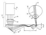
- a light-guiding element 26e.g., a prism 28 is coupled to eyeglasses frame 22 .
- An optical elemente.g. a coupling-in element 62 , is positioned to converge beam 40 emitted from power source 24 to a converging light beam.
- Prism 28is shaped and positioned to convey the converging beam through at least a portion of the prism 28 , and arranged such that a diverging beam is conveyed toward the eye of the subject.
- more than one, but typically not more than ten, coupling-out elementare optically coupled to guide 26 .
- the optical coupling-out elementsare positioned such that there is a space, D 3 , of at least 1 mm distance between the optical coupling-out elements, the space not containing an optical coupling-out element. Accordingly, due to the number and spacing of the coupling-out elements, they do not function as pixels for projecting an image towards the eye.
- FIG. 7is a block diagram of components of apparatus comprising an extraocular device, in accordance with some applications of the present invention.
- external device 20comprises a user interface element 65 (e.g., a dial, switch, or button), a controller 66 and a modulating unit 68 , coupled to eyeglasses frame 22 , allowing the subject to interactively control characteristics of the beam emitted from power source 24 , e.g., by using the beam to send non-image data to the retinal prosthesis, in addition to transmitting power to the prosthesis.
- a user interface element 65e.g., a dial, switch, or button
- controller 66e.g., a controller 66 and a modulating unit 68
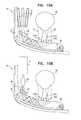
- FIG. 9is a schematic illustration of extraocular device 20 , in accordance with some applications of the present invention.
- light-guiding element 26comprises an optical fiber 29 .
- an eyeglasses lens 55is coupled to frame 22 , and optical fiber 29 is embedded within the eyeglasses lens and positioned to emit light toward eye 30 of the subject.
- extraocular device 20comprises optical coupling-out elements 1720 , 1740 , and 1760 , which are optically coupled to discrete locations of element 26 such that when a gaze of the subject changes, power still enters eye 30 through at least one of the optical coupling-out elements.
- coupling-out elements 1720 , 1740 and 1760 shown in FIGS. 10A-Bare the same as coupling-out elements 62 and 64 , except for differences described herein with reference to FIGS. 10A-B .
Landscapes
- Physics & Mathematics (AREA)
- Health & Medical Sciences (AREA)
- Optics & Photonics (AREA)
- General Physics & Mathematics (AREA)
- General Health & Medical Sciences (AREA)
- Ophthalmology & Optometry (AREA)
- Public Health (AREA)
- Animal Behavior & Ethology (AREA)
- Life Sciences & Earth Sciences (AREA)
- Veterinary Medicine (AREA)
- Radiology & Medical Imaging (AREA)
- Nuclear Medicine, Radiotherapy & Molecular Imaging (AREA)
- Biomedical Technology (AREA)
- Engineering & Computer Science (AREA)
- Acoustics & Sound (AREA)
- Otolaryngology (AREA)
- Prostheses (AREA)
- Eye Examination Apparatus (AREA)
Abstract
Description
- the coupling-in element being positioned such that the beam of light is directed into the light-guiding element via the coupling-in element, and
- the coupling-in and coupling-out elements being positioned such that the beam diverges from a focal point located within 3 mm of the coupling-out element.
- (a) the first optical coupling-out element is configured to allow less than all of the light beam to leave the light-guiding element, and
- (b) the second optical coupling-out element is configured to allow at least some of the remaining light to leave the light-guiding element.
Claims (12)
Priority Applications (5)
| Application Number | Priority Date | Filing Date | Title |
|---|---|---|---|
| US14/145,470US9474902B2 (en) | 2013-12-31 | 2013-12-31 | Wearable apparatus for delivery of power to a retinal prosthesis |
| EP14827551.4AEP3089784B1 (en) | 2013-12-31 | 2014-12-30 | Wearable apparatus for delivery of power to a retinal prosthesis |
| PCT/IB2014/067417WO2015101932A2 (en) | 2013-12-31 | 2014-12-30 | Wearable apparatus for delivery of power to a retinal prosthesis |
| CN201420858861.9UCN205007073U (en) | 2013-12-31 | 2014-12-30 | Device including outer equipment of eye |
| CN201410850334.8ACN104739544B (en) | 2013-12-31 | 2014-12-30 | Wearable device for providing from energy to retina prosthese |
Applications Claiming Priority (1)
| Application Number | Priority Date | Filing Date | Title |
|---|---|---|---|
| US14/145,470US9474902B2 (en) | 2013-12-31 | 2013-12-31 | Wearable apparatus for delivery of power to a retinal prosthesis |
Publications (2)
| Publication Number | Publication Date |
|---|---|
| US20150182748A1 US20150182748A1 (en) | 2015-07-02 |
| US9474902B2true US9474902B2 (en) | 2016-10-25 |
Family
ID=52350170
Family Applications (1)
| Application Number | Title | Priority Date | Filing Date |
|---|---|---|---|
| US14/145,470Expired - Fee RelatedUS9474902B2 (en) | 2013-12-31 | 2013-12-31 | Wearable apparatus for delivery of power to a retinal prosthesis |
Country Status (4)
| Country | Link |
|---|---|
| US (1) | US9474902B2 (en) |
| EP (1) | EP3089784B1 (en) |
| CN (2) | CN104739544B (en) |
| WO (1) | WO2015101932A2 (en) |
Cited By (7)
| Publication number | Priority date | Publication date | Assignee | Title |
|---|---|---|---|---|
| DE102017107346A1 (en) | 2017-04-05 | 2018-10-11 | Carl Zeiss Ag | Device for power supply of and / or communication with an eye implant by means of illumination radiation |
| US10226625B2 (en) | 2016-11-03 | 2019-03-12 | Nano Retina Ltd. | Surgical techniques for implantation of a retinal implant |
| US10272244B2 (en) | 2016-11-03 | 2019-04-30 | Nano Retina Ltd. | Retinal implant fixation |
| US10583283B2 (en) | 2018-01-31 | 2020-03-10 | Nano-Retina, Inc. | Retinal implant with image registration |
| US20220203106A1 (en)* | 2019-04-03 | 2022-06-30 | Carl Zeiss Ag | Device for supplying energy to an active eye implant |
| US12128243B2 (en) | 2019-04-03 | 2024-10-29 | Carl Zeiss Ag | Devices for supplying energy to an active eye implant |
| US12193928B2 (en) | 2020-03-23 | 2025-01-14 | Tectus Corporation | Intraocular femtoprojector |
Families Citing this family (28)
| Publication number | Priority date | Publication date | Assignee | Title |
|---|---|---|---|---|
| IL166799A (en) | 2005-02-10 | 2014-09-30 | Lumus Ltd | Substrate-guided optical device utilizing beam splitters |
| IL235642B (en) | 2014-11-11 | 2021-08-31 | Lumus Ltd | Compact head-mounted display system protected by a hyperfine structure |
| WO2017100545A1 (en) | 2015-12-10 | 2017-06-15 | Nano-Retina, Inc. | Techniques for data retention in memory cells during power interruption |
| CN105662704B (en)* | 2015-12-29 | 2017-10-20 | 深圳先进技术研究院 | Ultrasonic retina stimulation apparatus |
| CN105435379B (en)* | 2015-12-29 | 2018-11-02 | 深圳先进技术研究院 | Retina stimulation apparatus based on two-dimensional array probe |
| CN105404027B (en)* | 2015-12-31 | 2018-09-11 | 白云供电局 | A kind of wireless charging wifi camera glasses and mating wireless power supply |
| DE102016103285A1 (en)* | 2016-02-24 | 2017-08-24 | Carl Zeiss Ag | Device and method for supplying a retinal implant |
| JP6740366B2 (en)* | 2016-05-18 | 2020-08-12 | ルーマス リミテッドLumus Ltd. | Head mount imaging device |
| WO2018065975A1 (en) | 2016-10-09 | 2018-04-12 | Lumus Ltd | Aperture multiplier using a rectangular waveguide |
| KR20240160657A (en) | 2016-11-08 | 2024-11-11 | 루머스 리미티드 | Light-guide device with optical cutoff edge and corresponding production methods |
| WO2018140938A1 (en)* | 2017-01-30 | 2018-08-02 | The Charles Stark Draper Laboratory, Inc. | Saw modulators and light steering methods |
| CN115166977B (en)* | 2017-02-13 | 2025-04-25 | 视瑞尔技术公司 | Light guide device and display device for representing a scene |
| CN108738358B (en) | 2017-02-22 | 2021-03-26 | 鲁姆斯有限公司 | Light guide optics |
| IL251645B (en)* | 2017-04-06 | 2018-08-30 | Lumus Ltd | Light-guide optical element and method of its manufacture |
| EP4215980A1 (en) | 2017-07-19 | 2023-07-26 | Lumus Ltd. | Lcos illumination via loe |
| EP3685215B1 (en) | 2017-09-21 | 2024-01-03 | Magic Leap, Inc. | Augmented reality display with waveguide configured to capture images of eye and/or environment |
| WO2019102366A1 (en) | 2017-11-21 | 2019-05-31 | Lumus Ltd. | Optical aperture expansion arrangement for near-eye displays |
| FI128552B (en)* | 2018-03-28 | 2020-07-31 | Dispelix Oy | Waveguide display element with reflector surface |
| US11415812B2 (en) | 2018-06-26 | 2022-08-16 | Lumus Ltd. | Compact collimating optical device and system |
| WO2020069037A1 (en) | 2018-09-26 | 2020-04-02 | Magic Leap, Inc. | Eyewear with pinhole and slit cameras |
| EP3956604A4 (en) | 2019-04-15 | 2022-06-08 | Lumus Ltd. | PROCESS FOR MANUFACTURING AN OPTICAL LIGHT GUIDE ELEMENT |
| CA3137994A1 (en) | 2019-06-27 | 2020-12-30 | Lumus Ltd | Apparatus and methods for eye tracking based on eye imaging via a light-guide optical element |
| KR20220035088A (en) | 2019-07-18 | 2022-03-21 | 루머스 리미티드 | Encapsulated light guide optics |
| US11561336B2 (en) | 2019-10-05 | 2023-01-24 | Meta Platforms Technologies, Llc | Transparent illumination layer with transparent waveguide structure |
| TWI884834B (en) | 2019-12-05 | 2025-05-21 | 以色列商魯姆斯有限公司 | Optical device and method of fabricating optical device |
| WO2021121618A1 (en)* | 2019-12-20 | 2021-06-24 | Carl Zeiss Ag | Method for manufacturing eyeglass for providing light to an eye, blank and set of eyeglasses |
| KR102676604B1 (en) | 2021-07-04 | 2024-06-18 | 루머스 리미티드 | Display with stacked light guiding elements providing different parts of the field of view |
| CN115624381B (en)* | 2022-12-12 | 2023-05-09 | 北京国光领航科技有限公司 | Laser medical device with safety detection system |
Citations (282)
| Publication number | Priority date | Publication date | Assignee | Title |
|---|---|---|---|---|
| US1662446A (en) | 1924-01-14 | 1928-03-13 | Wappler Electric Company Inc | Metal-foil electrode |
| US2721316A (en) | 1953-06-09 | 1955-10-18 | Joseph D Shaw | Method and means for aiding the blind |
| US2760483A (en) | 1953-10-29 | 1956-08-28 | Tassicker Graham Edward | Retinal stimulator |
| US4197850A (en) | 1978-11-03 | 1980-04-15 | Pacesetter Systems, Inc. | Implantable human tissue stimulator with memory protect means |
| US4262294A (en) | 1977-08-09 | 1981-04-14 | Ricoh Company, Ltd. | Electrostatic printing apparatus comprising improved electrode drive means |
| US4272910A (en) | 1979-07-31 | 1981-06-16 | Danz W R | Ocular prosthetic or the like |
| US4324252A (en) | 1980-08-04 | 1982-04-13 | Medtronic, Inc. | Memory control circuitry for implantable medical devices |
| US4551149A (en) | 1982-02-16 | 1985-11-05 | Michael Sciarra | Prosthetic vision system |
| US4601545A (en) | 1984-05-16 | 1986-07-22 | Kern Seymour P | Variable power lens system |
| US4628933A (en) | 1985-07-23 | 1986-12-16 | Michelson Robin P | Method and apparatus for visual prosthesis |
| US4664117A (en) | 1984-10-09 | 1987-05-12 | Beck Stephen C | Apparatus and method for generating phosphenes |
| US4786818A (en) | 1987-11-09 | 1988-11-22 | California Institute Of Technology | Integrated sensor and processor for visual images |
| US4837049A (en) | 1986-06-17 | 1989-06-06 | Alfred E. Mann Foundation For Scientific Research | Method of making an electrode array |
| US4903702A (en) | 1988-10-17 | 1990-02-27 | Ad-Tech Medical Instrument Corporation | Brain-contact for sensing epileptogenic foci with improved accuracy |
| US4914738A (en) | 1987-09-10 | 1990-04-03 | Fuji Photo Film Co., Ltd. | Apparatus for discriminating light source having spectrum peaks |
| US4969468A (en) | 1986-06-17 | 1990-11-13 | Alfred E. Mann Foundation For Scientific Research | Electrode array for use in connection with a living body and method of manufacture |
| US5016633A (en) | 1989-08-08 | 1991-05-21 | Chow Alan Y | Artificial retina device |
| US5024223A (en) | 1989-08-08 | 1991-06-18 | Chow Alan Y | Artificial retina device |
| US5081378A (en) | 1990-01-19 | 1992-01-14 | Kabushiki Kaisha Toshiba | Logarithmic amplifier |
| US5108427A (en) | 1991-01-07 | 1992-04-28 | Majercik Stephen M | Active pupillary prosthesis |
| US5109844A (en) | 1990-10-11 | 1992-05-05 | Duke University | Retinal microstimulation |
| US5133356A (en) | 1991-04-16 | 1992-07-28 | Minnesota Mining And Manufacturing Company | Biomedical electrode having centrally-positioned tab construction |
| US5147284A (en) | 1989-08-17 | 1992-09-15 | Fedorov Svjatoslav N | Device and method for restoration of visual functions |
| US5159927A (en) | 1989-07-26 | 1992-11-03 | Ferdinand Schmid | Visual prosthesis apparatus and method |
| US5215088A (en) | 1989-11-07 | 1993-06-01 | The University Of Utah | Three-dimensional electrode device |
| US5313642A (en) | 1990-10-03 | 1994-05-17 | Seagull Scientific Systems, Inc. | Power interface for peripheral devices |
| US5314458A (en) | 1990-06-01 | 1994-05-24 | University Of Michigan | Single channel microstimulator |
| US5397350A (en) | 1993-05-03 | 1995-03-14 | Chow; Alan Y. | Independent photoelectric artificial retina device and method of using same |
| US5411540A (en) | 1993-06-03 | 1995-05-02 | Massachusetts Institute Of Technology | Method and apparatus for preferential neuron stimulation |
| US5476494A (en) | 1992-09-11 | 1995-12-19 | Massachusetts Institute Of Technology | Low pressure neural contact structure |
| US5526423A (en) | 1991-05-08 | 1996-06-11 | Canon Kabushiki Kaisha | Communication apparatus and method with service execution according to dial number |
| US5556423A (en) | 1993-05-03 | 1996-09-17 | Alan Y. Chow | Independent photoelectric artificial retina device and method of using same |
| US5597381A (en) | 1993-06-03 | 1997-01-28 | Massachusetts Eye And Ear Infirmary | Methods for epi-retinal implantation |
| US5608204A (en) | 1992-03-24 | 1997-03-04 | Institut Fur Mikroelektronik Stuttgart | Image cell for an image-recorder chip, for protection of high input signal dynamics onto reduced output signal dynamics |
| US5674263A (en) | 1995-04-26 | 1997-10-07 | Yamamoto; Hiroshi | Optic nerve image output device and method |
| US5735882A (en) | 1996-11-25 | 1998-04-07 | Sulzer Intermedics Inc. | Cardiac stimulator with backup-mode self-recovery |
| US5769875A (en) | 1994-09-06 | 1998-06-23 | Case Western Reserve University | Functional neuromusclar stimulation system |
| US5800533A (en) | 1996-03-18 | 1998-09-01 | Harry C. Eggleston | Adjustable intraocular lens implant with magnetic adjustment facilities |
| US5800478A (en) | 1996-03-07 | 1998-09-01 | Light Sciences Limited Partnership | Flexible microcircuits for internal light therapy |
| US5800535A (en) | 1994-02-09 | 1998-09-01 | The University Of Iowa Research Foundation | Wireless prosthetic electrode for the brain |
| US5805267A (en) | 1996-06-13 | 1998-09-08 | Goldman; Neil | Interactive light field for programmed non-visual stimulation and monitoring |
| US5835250A (en) | 1995-08-23 | 1998-11-10 | Fujitsu Limited | Device for driving light emitting element |
| US5836996A (en) | 1996-12-30 | 1998-11-17 | Doorish; John F. | Artificial retina |
| US5837995A (en) | 1996-11-25 | 1998-11-17 | Alan Y. Chow | Wavelength-controllable voltage-phase photodiode optoelectronic switch ("opsistor") |
| US5850514A (en) | 1996-03-18 | 1998-12-15 | Nissan Motor Co., Ltd. | Malfunction monitoring circuit of microcomputer system |
| US5865839A (en) | 1996-12-30 | 1999-02-02 | Doorish; John F. | Artificial retina |
| US5873901A (en) | 1995-06-30 | 1999-02-23 | Space Vacuum Epitaxy Center University Of Houston | Treating retinal damage by implanting thin film optical detectors |
| US5895415A (en) | 1995-06-06 | 1999-04-20 | Optobionics Corporation | Multi-phasic microphotodiode retinal implant and adaptive imaging retinal stimulation system |
| US5935155A (en) | 1998-03-13 | 1999-08-10 | John Hopkins University, School Of Medicine | Visual prosthesis and method of using same |
| US5944747A (en) | 1998-03-13 | 1999-08-31 | Johns Hopkins University | Method for preferential outer retinal stimulation |
| US6032062A (en) | 1995-08-10 | 2000-02-29 | Nmi Naturwissenschaftliches Und Medizinisches Institut | Microelectrode arrangement |
| US6035236A (en) | 1998-07-13 | 2000-03-07 | Bionergy Therapeutics, Inc. | Methods and apparatus for electrical microcurrent stimulation therapy |
| US6043437A (en) | 1996-12-20 | 2000-03-28 | Alfred E. Mann Foundation | Alumina insulation for coating implantable components and other microminiature devices |
| US6069365A (en) | 1997-11-25 | 2000-05-30 | Alan Y. Chow | Optical processor based imaging system |
| JP2000350742A (en) | 1999-06-11 | 2000-12-19 | Sumitomo Heavy Ind Ltd | Control method and apparatus of eyeball irradiating radiation |
| US6230057B1 (en) | 1995-06-06 | 2001-05-08 | Optobionics Corporation | Multi-phasic microphotodiode retinal implant and adaptive imaging retinal stimulation system |
| US6235046B1 (en) | 1998-01-21 | 2001-05-22 | David W. Gerdt | Passive photonic eye delivery system |
| US6259937B1 (en) | 1997-09-12 | 2001-07-10 | Alfred E. Mann Foundation | Implantable substrate sensor |
| US20010011844A1 (en) | 1996-09-26 | 2001-08-09 | Edmund Ernst | Method and arrangement for controlling functions in a programme- controlled circuit in the event of operating voltage failure |
| US6287372B1 (en) | 2000-03-31 | 2001-09-11 | Themec Company Incorporated | Anti-corrosive coating |
| US6298270B1 (en) | 1996-10-23 | 2001-10-02 | Eberhard-Karls-Universitat Tubingen Universitatsklinkum | Retina implant |
| US6319273B1 (en) | 1999-12-16 | 2001-11-20 | Light Sciences Corporation | Illuminating device for treating eye disease |
| US6324429B1 (en) | 1998-05-08 | 2001-11-27 | Massachusetts Eye And Ear Infirmary | Chronically implantable retinal prosthesis |
| WO2001091854A1 (en) | 2000-05-31 | 2001-12-06 | Impulse Dynamics Nv | Electropancreatography |
| US6347250B1 (en) | 1996-10-23 | 2002-02-12 | Nmi Univ Tuebingen | Optically controllable microelectrode array for stimulating cells within a tissue |
| US6368349B1 (en) | 2000-11-21 | 2002-04-09 | Massachusetts Institute Of Technology | Inflatable neural prosthesis |
| US6389317B1 (en) | 2000-03-31 | 2002-05-14 | Optobionics Corporation | Multi-phasic microphotodetector retinal implant with variable voltage and current capability |
| US6400989B1 (en) | 1997-02-21 | 2002-06-04 | Intelligent Implants Gmbh | Adaptive sensory-motor encoder for visual or acoustic prosthesis |
| US20020091421A1 (en) | 1999-03-24 | 2002-07-11 | Greenberg Robert J. | Electrode array for neural stimulation |
| US6427087B1 (en) | 2000-05-04 | 2002-07-30 | Optobionics Corporation | Artificial retina device with stimulating and ground return electrodes disposed on opposite sides of the neuroretina and method of attachment |
| US6442431B1 (en) | 1998-07-27 | 2002-08-27 | Axon Engineering, Inc., | Device and method for production of visual sensations by optic nerve stimulation |
| US6458157B1 (en) | 1997-08-04 | 2002-10-01 | Suaning Gregg Joergen | Retinal stimulator |
| US6473365B2 (en) | 2000-08-04 | 2002-10-29 | Agency For Defense Development | Supporting structure of hydrophones for towed array sonar system |
| US6507758B1 (en) | 1999-03-24 | 2003-01-14 | Second Sight, Llc | Logarithmic light intensifier for use with photoreceptor-based implanted retinal prosthetics and those prosthetics |
| US20030023297A1 (en) | 2001-06-18 | 2003-01-30 | Byers Charles L. | Miniature implantable array and stimulation system suitable for eyelid stimulation |
| US20030032946A1 (en) | 2001-06-29 | 2003-02-13 | Fishman Harvey A. | Artificial synapse chip interface for electronic prosthetic retina |
| US6533798B2 (en) | 1999-01-05 | 2003-03-18 | Second Sight, Llc | Intraocular electrode |
| US20030086064A1 (en) | 2001-11-06 | 2003-05-08 | Sutter Erich E | Head mounted infrared fundus illuminator |
| US20030100823A1 (en) | 2000-03-29 | 2003-05-29 | Daryl Kipke | Device for creating a neural interface and method for making same |
| US6574022B2 (en) | 2001-03-19 | 2003-06-03 | Alan Y. Chow | Integral differential optical signal receiver |
| US20030132946A1 (en) | 2002-01-11 | 2003-07-17 | Applied Materials, Inc. | System and method for edge ehnancement of images |
| US20030208248A1 (en) | 2000-01-07 | 2003-11-06 | John Carter | Percutaneous electrode array |
| US6647297B2 (en) | 2000-08-09 | 2003-11-11 | The United States Of America As Represented By The Secretary Of The Navy | Permanent retinal implant device |
| US6658299B1 (en) | 2000-01-04 | 2003-12-02 | William H. Dobelle | Artificial system for vision and the like |
| US6678458B2 (en) | 2001-08-17 | 2004-01-13 | Zynex Corporation | System and method for precise positioning of microcomponents |
| US6677225B1 (en) | 2000-07-14 | 2004-01-13 | Zyvex Corporation | System and method for constraining totally released microcomponents |
| US6683645B1 (en) | 1995-12-01 | 2004-01-27 | Qinetiq Limited | Imaging system with low sensitivity to variation in scene illumination |
| US20040054407A1 (en) | 2002-08-30 | 2004-03-18 | Nidek Co., Ltd. | Artificial vision system |
| US20040078064A1 (en) | 2001-03-03 | 2004-04-22 | Satoshi Suzuki | Electrode member for retinal stimulation, and artificial retinal device using the electrode member |
| US20040080026A1 (en) | 2002-10-24 | 2004-04-29 | Matsushita Electric Industrial Co., Ltd. | Leadframe, plastic-encapsulated semiconductor device, and method for fabricating the same |
| US6738672B2 (en) | 2001-06-18 | 2004-05-18 | The Alfred E. Mann Foundation For Scientific Research | Miniature implantable connectors |
| US20040098067A1 (en) | 2001-02-28 | 2004-05-20 | Jun Ohta | Built-in-eye- eyesight stimulating apparatus |
| WO2003032946A3 (en) | 2001-10-12 | 2004-06-10 | United Therapeutics Corp | Ph-sensitive liposomes for targeted drug delivery |
| US6755530B1 (en) | 2002-07-16 | 2004-06-29 | The United States Of America As Represented By The Administrator Of The National Aeronautics And Space Administration | Retinal light processing using carbon nanotubes |
| US6758823B2 (en) | 2001-02-09 | 2004-07-06 | Massachusetts Eye & Ear Infirmary | Assessment of retinal function |
| US6761724B1 (en) | 1997-09-19 | 2004-07-13 | Eberhard-Karls-Universität Tübingen Universitätsklinikum | Method and device for entering the subretinal region of the eye |
| US6762116B1 (en) | 2002-06-12 | 2004-07-13 | Zyvex Corporation | System and method for fabricating microcomponent parts on a substrate having pre-fabricated electronic circuitry thereon |
| US6770521B2 (en) | 2001-11-30 | 2004-08-03 | Texas Instruments Incorporated | Method of making multiple work function gates by implanting metals with metallic alloying additives |
| US6785303B1 (en) | 1999-03-12 | 2004-08-31 | Max-Planck-Gesellschaft Zur Forderung Der Wissenschaften E. V. | Generation of stabilized, ultra-short light pulses and the use thereof for synthesizing optical frequencies |
| US20040181265A1 (en) | 2003-02-14 | 2004-09-16 | Palanker Daniel V. | Self-sufficient retinal prosthesis powered by intraocular photovoltaic cells |
| US20040189940A1 (en) | 1999-12-13 | 2004-09-30 | Ernst Kutschbach | Method and system for determining the topography for reaction signals of an eye |
| US6804560B2 (en) | 1999-05-07 | 2004-10-12 | Eberhard-Karls-Universitat Tubingen Universitatsklinikum | Retina implant |
| DE10315397A1 (en) | 2003-04-04 | 2004-10-14 | Carl Zeiss | Energy supply device for a retina implant |
| US6821154B1 (en) | 2003-10-03 | 2004-11-23 | Alfred E. Mann Foundation For Scientific Research | Electrical device connector and method therefor |
| US20050015120A1 (en) | 2003-07-11 | 2005-01-20 | Seibel Eric J. | Scanning laser device and methods of use |
| US20050013005A1 (en) | 2003-05-22 | 2005-01-20 | Rogers John R. | Optical combiner designs and head mounted displays |
| US6847847B2 (en) | 1999-05-07 | 2005-01-25 | Eberhard-Karls Universitat Tubingen, Universitatsklinikum | Retina implant assembly and methods for manufacturing the same |
| US6888571B1 (en) | 1999-09-27 | 2005-05-03 | Casio Computer Co., Ltd. | Photosensor system and drive control method thereof |
| US20050119605A1 (en) | 2002-04-19 | 2005-06-02 | Transpharma Medical Ltd. | Handheld transdermal drug delivery and analyte extraction |
| US6904239B2 (en) | 2001-04-05 | 2005-06-07 | Alan Chow | Wavelength associative addressing system for WDM type light packet steering |
| US6908470B2 (en) | 2001-01-11 | 2005-06-21 | Fraunhofer-Gesellschaft Zur Foderung Der Angewandten Forschung E.V. | Sieve electrode which can be connected to a nerve stump |
| US20050146954A1 (en) | 2002-03-05 | 2005-07-07 | Naing Win | Product and method for preventing incorrect storage of data |
| US6923669B1 (en) | 2004-02-13 | 2005-08-02 | Zyvex Corporation | Microconnectors and non-powered microassembly therewith |
| US20050168569A1 (en) | 2004-01-29 | 2005-08-04 | Konica Minolta Photo Imaging, Inc. | Visual aid display apparatus |
| US6935897B2 (en) | 2003-10-03 | 2005-08-30 | Alfred E. Mann Foundation For Scientific Research | Electrical device connector and method therefor |
| US6949763B2 (en) | 2001-10-11 | 2005-09-27 | Marc Ovadia | Semiconductor and non-semiconductor non-diffusion-governed bioelectrodes |
| US6961619B2 (en) | 2000-08-29 | 2005-11-01 | Casey Don E | Subcutaneously implantable power supply |
| US6970745B2 (en) | 2000-08-09 | 2005-11-29 | The United States Of America As Represented By The Secretary Of The Navy | Microelectronic stimulator array for stimulating nerve tissue |
| US6974533B2 (en) | 2002-04-11 | 2005-12-13 | Second Sight Medical Products, Inc. | Platinum electrode and method for manufacturing the same |
| US6976998B2 (en) | 2002-01-17 | 2005-12-20 | Massachusetts Institute Of Technology | Minimally invasive retinal prosthesis |
| US6990377B2 (en) | 2003-04-24 | 2006-01-24 | Northstar Neuroscience, Inc. | Systems and methods for facilitating and/or effectuating development, rehabilitation, restoration, and/or recovery of visual function through neural stimulation |
| US7027874B1 (en) | 2000-11-16 | 2006-04-11 | Polyvalor S.E.C. | Body electronic implant and artificial vision system thereof |
| US7025619B2 (en) | 2004-02-13 | 2006-04-11 | Zyvex Corporation | Sockets for microassembly |
| US7031776B2 (en) | 2001-06-29 | 2006-04-18 | Optobionics | Methods for improving damaged retinal cell function |
| US7035692B1 (en) | 2003-04-30 | 2006-04-25 | The Regents Of The University Of California | High density polymer-based integrated electrode array |
| US7037943B2 (en) | 2001-04-10 | 2006-05-02 | Optobionics Corporation | Retinal treatment method |
| US20060111757A9 (en) | 2004-05-25 | 2006-05-25 | Robert Greenberg | Retinal prosthesis |
| CA2235216C (en) | 1995-10-19 | 2006-05-30 | The University Of Melbourne | Embedded data link and protocol |
| US7058455B2 (en) | 2003-02-14 | 2006-06-06 | The Board Of Trustees Of The Leland Stanford Junior University | Interface for making spatially resolved electrical contact to neural cells in a biological neural network |
| US20060136018A1 (en) | 2003-05-01 | 2006-06-22 | Leon Lack | Apparatus for administering light stimulation |
| US7071546B2 (en) | 2002-01-16 | 2006-07-04 | Alfred E. Mann Foundation For Scientific Research | Space-saving packaging of electronic circuits |
| US7081630B2 (en) | 2004-03-12 | 2006-07-25 | Zyvex Corporation | Compact microcolumn for automated assembly |
| US20060184245A1 (en) | 2003-06-23 | 2006-08-17 | Heinz-Gerhard Graf | Active retina implant with a multiplicity of pixel elements |
| US7096568B1 (en) | 2003-07-10 | 2006-08-29 | Zyvex Corporation | Method of manufacturing a microcomponent assembly |
| US7103416B2 (en) | 2001-01-16 | 2006-09-05 | Second Sight Medical Products, Inc. | Visual prosthesis including enhanced receiving and stimulating portion |
| US7107097B2 (en) | 2004-01-14 | 2006-09-12 | Northstar Neuroscience, Inc. | Articulated neural electrode assembly |
| US7127286B2 (en) | 2001-02-28 | 2006-10-24 | Second Sight Medical Products, Inc. | Implantable device using ultra-nanocrystalline diamond |
| US7127301B1 (en) | 2003-04-28 | 2006-10-24 | Sandia Corporation | Flexible retinal electrode array |
| US7130693B1 (en) | 2004-07-07 | 2006-10-31 | National Semiconductor Corporation | Method for increasing the resolution and decreasing the power dissipation in eye prosthetics |
| US20060256989A1 (en) | 2003-03-17 | 2006-11-16 | Olsen Henrik B | Hearing prosthesis comprising rechargeable battery information |
| US7147865B2 (en) | 2001-06-29 | 2006-12-12 | The Board Of Trustees Of The Leland Stanford University | Artificial synapse chip |
| US7149586B2 (en) | 2002-03-28 | 2006-12-12 | Second Sight Medical Products, Inc. | Variable pitch electrode array |
| CN1875895A (en) | 2006-04-19 | 2006-12-13 | 华中科技大学 | A flexible retina chip and preparation method thereof |
| US20060282128A1 (en) | 2005-04-28 | 2006-12-14 | California Institute Of Technology | Batch-fabricated flexible intraocular retinal prosthesis system and method for manufacturing the same |
| US20060287688A1 (en) | 2005-03-31 | 2006-12-21 | Nidek Co., Ltd. | Vision regeneration assisting apparatus |
| US7158834B2 (en) | 2002-06-13 | 2007-01-02 | Atlantic Medical, Inc. | Method and apparatus for performing microcurrent stimulation (MSC) therapy |
| US20070005116A1 (en) | 2005-06-30 | 2007-01-04 | Lsi Logic Corporation | Implantable, fully integrated and high performance semiconductor device for retinal prostheses |
| US7162308B2 (en) | 2002-11-26 | 2007-01-09 | Wilson Greatbatch Technologies, Inc. | Nanotube coatings for implantable electrodes |
| US7177697B2 (en) | 2001-04-28 | 2007-02-13 | Intelligent Acquisition Llc | Microcontact structure for implantation in a mammal, especially a human being |
| US20070047091A1 (en) | 2005-03-22 | 2007-03-01 | The Microoptical Corporaiton | Optical system using total internal reflection images |
| US7190051B2 (en) | 2003-01-17 | 2007-03-13 | Second Sight Medical Products, Inc. | Chip level hermetic and biocompatible electronics package using SOI wafers |
| US20070064310A1 (en) | 2004-03-08 | 2007-03-22 | Sony Corporation | Image display apparatus |
| WO2007006376A3 (en) | 2005-07-14 | 2007-04-12 | Imi Intelligent Med Implants | Extraocular epiretinal implant |
| US7224301B2 (en) | 2001-11-30 | 2007-05-29 | Second Sight Medical Products, Inc. | Floating gate digital-to-analog converter |
| US20070123766A1 (en) | 2005-09-29 | 2007-05-31 | Whalen John J Iii | Microelectrode systems for neuro-stimulation and neuro-sensing and microchip packaging and related methods |
| US20070142877A1 (en) | 2005-12-20 | 2007-06-21 | Mclean George Y | Charge-integrating retinal prosthesis and method |
| US20070142878A1 (en) | 2001-11-16 | 2007-06-21 | The Regrets Of The University Of California | Flexible electrode array for artificial vision |
| US7242597B2 (en) | 2004-08-04 | 2007-07-10 | Nidek Co., Ltd. | Rectifier circuit and vision regeneration assisting apparatus having the same |
| US7244027B2 (en) | 2004-06-30 | 2007-07-17 | Nidek Co., Ltd. | Perimeter |
| US7248928B2 (en) | 2001-03-30 | 2007-07-24 | Nidek Co., Ltd. | Artificial eye system |
| US7251528B2 (en) | 2004-02-06 | 2007-07-31 | Scyfix, Llc | Treatment of vision disorders using electrical, light, and/or sound energy |
| US7255871B2 (en) | 2002-05-08 | 2007-08-14 | The Board Of Trustees Of The Leland Stanford Junior University | Nanotube mat with an array of conduits for biological cells |
| US7257446B2 (en) | 1999-03-24 | 2007-08-14 | Second Sight Medical Products, Inc. | Package for an implantable medical device |
| US20070191909A1 (en) | 2006-02-15 | 2007-08-16 | Doheny Eye Institute | Wide-field retinal prosthesis |
| WO2007009539A3 (en) | 2005-07-15 | 2007-09-07 | Topotarget Germany Ag | Use of inhibitors of histone deacetylases in combination with nsaid for the therapy of cancer and/or inflammatory diseases |
| US7272447B2 (en) | 2001-10-17 | 2007-09-18 | Retina Implant Gmbh | Electrode arrangement for electrical stimulation of biological material, and a multi-electrode array for use in such an electrode arrangement |
| US7271525B2 (en) | 2003-01-15 | 2007-09-18 | Alfred E. Mann Foundation For Scientific Research | Piezoelectric device mounted on integrated circuit chip |
| US7295872B2 (en) | 2001-10-10 | 2007-11-13 | Massachusetts Institute Of Technology | System for and method of power efficient electrical tissue stimulation |
| US7302598B2 (en) | 2001-10-26 | 2007-11-27 | Fujitsu Limited | Apparatus to reduce the internal frequency of an integrated circuit by detecting a drop in the voltage and frequency |
| US7321796B2 (en) | 2003-05-01 | 2008-01-22 | California Institute Of Technology | Method and system for training a visual prosthesis |
| US7342427B1 (en) | 2005-12-19 | 2008-03-11 | National Semiconductor Corporation | Automatic clock based power-down circuit |
| US20080114230A1 (en) | 2006-11-14 | 2008-05-15 | Bruce Addis | Electrode support |
| US7377646B2 (en) | 2004-06-01 | 2008-05-27 | Nidek Co., Ltd. | Perimeter |
| US7388288B2 (en) | 2006-07-17 | 2008-06-17 | University Of Utah Research Foundation | Flip chip metallization method and devices |
| US7400021B2 (en) | 2002-06-15 | 2008-07-15 | The University Of Houston System | Thin film optical detectors for retinal implantation and methods for making and using same |
| US20080234791A1 (en) | 2007-01-17 | 2008-09-25 | Jeffrey Edward Arle | Spinal cord implant systems and methods |
| US20080247722A1 (en) | 2005-09-19 | 2008-10-09 | Koninklijke Philips Electronics, N.V. | Waveguide and Lighting Device |
| US20080262571A1 (en) | 2006-10-20 | 2008-10-23 | Greenberg Robert J | Visual Prosthesis |
| US7447548B2 (en) | 2001-11-09 | 2008-11-04 | Imi Intelligent Medical Implants Ag | Retinal implant with improved implantation and working properties |
| US7447547B2 (en) | 2003-02-14 | 2008-11-04 | The Board Of Trustees Of The Leland Stanford Junior University | Neural prosthesis based on photomechanical deflectors and tactile sensory cells |
| US20080288067A1 (en) | 2007-05-10 | 2008-11-20 | Newcyte, Inc. | Artificial retinal implant |
| US20080288036A1 (en) | 2007-02-16 | 2008-11-20 | Greenberg Robert J | Flexible Circuit Electrode Array with Wire or Film Support |
| US20090002034A1 (en) | 2006-02-09 | 2009-01-01 | Nxp B.V. | Circuit Arrangement and Method for Detecting a Power Down Situation of a Voltage Supply Source |
| US20090024182A1 (en) | 2004-10-21 | 2009-01-22 | Fengyan Zhang | IrOx Nanostructure Electrode Neural Interface Optical Device |
| US7481912B2 (en) | 2001-04-17 | 2009-01-27 | NMI Naturwissenschaftliches und Medizinisches Institut an der Universität Tuebingen | Pair of measuring electrodes, biosensor comprising a pair of measuring electrodes of this type, and production process |
| US7480988B2 (en) | 2001-03-30 | 2009-01-27 | Second Sight Medical Products, Inc. | Method and apparatus for providing hermetic electrical feedthrough |
| US7483751B2 (en) | 2004-06-08 | 2009-01-27 | Second Sight Medical Products, Inc. | Automatic fitting for a visual prosthesis |
| US20090040461A1 (en) | 2005-04-03 | 2009-02-12 | Ben Gurion Univ. Of The Negev Resea. & Dev. Auth. | Low vision aid device |
| US20090118805A1 (en) | 2007-07-05 | 2009-05-07 | Greenberg Robert J | Return Electrode for a Flexible Circuit Electrode Array |
| US7542209B2 (en) | 2004-09-01 | 2009-06-02 | Optical Research Associates | Compact head mounted display devices with tilted/decentered lens element |
| US20090147331A1 (en) | 2005-09-12 | 2009-06-11 | Elbit Systems Ltd | Near eye display system |
| US7556621B2 (en) | 2001-06-29 | 2009-07-07 | The Board Of Trustees Of The Leland Stanford Junior University | Optically controlled microfluidic chip |
| US7565202B2 (en) | 2002-07-30 | 2009-07-21 | Second Sight Medical Products, Inc. | Field focusing and mapping in an electrode array |
| US20090192571A1 (en) | 2006-10-10 | 2009-07-30 | Nmi Naturwissenschaftliches Und Medizinsches Institut An Der Universitaet Tuebingen | Device with a base body |
| US7571004B2 (en) | 2005-01-26 | 2009-08-04 | Second Sight Medical Products, Inc. | Neural stimulation for increased persistence |
| US7571011B2 (en) | 2003-05-01 | 2009-08-04 | Second Sight Medical Products, Inc. | Adherent metal oxide coating forming a high surface area electrode |
| US7574263B2 (en) | 2003-01-31 | 2009-08-11 | Second Sight Medical Products, Inc. | Pixel re-mapping for visual prosthesis |
| US20090204207A1 (en) | 2007-02-23 | 2009-08-13 | Pixeloptics, Inc. | Advanced Electro-Active Optic Device |
| US20090216295A1 (en) | 2006-04-28 | 2009-08-27 | Eberhart Zrenner | Active sub-retina implant |
| US20090228069A1 (en) | 2006-11-14 | 2009-09-10 | Rongqing Dai | Power Scheme for Implant Stimulators on the Human or Animal Body |
| US7595933B2 (en) | 2006-10-13 | 2009-09-29 | Apple Inc. | Head mounted display system |
| US20090287275A1 (en) | 2004-04-22 | 2009-11-19 | Gregg Jorgen Suaning | Electrode multiplexing method for retinal prosthesis |
| US7622702B2 (en) | 2007-09-12 | 2009-11-24 | National Chiao Tung University | Power controlling apparatus applied to biochip and operating method thereof |
| US7630771B2 (en) | 2007-06-25 | 2009-12-08 | Microtransponder, Inc. | Grooved electrode and wireless microtransponder system |
| US7631424B2 (en) | 2005-04-28 | 2009-12-15 | Second Sight Medical Products, Inc. | Method of making electrode array with a tack opening |
| US7638032B2 (en) | 2006-07-26 | 2009-12-29 | Second Sight Medical Products, Inc. | Process for cathodic protection of electrode materials |
| US7643214B2 (en) | 2004-06-17 | 2010-01-05 | Lumus Ltd. | Substrate-guided optical device with wide aperture |
| US7666523B2 (en) | 2005-10-26 | 2010-02-23 | Second Sight Medical Products, Inc. | Electrode surface coating and method for manufacturing the same |
| US7676274B2 (en) | 2001-05-01 | 2010-03-09 | Second Sight Medical Products, Inc. | High-density array of micro-machined electrodes for neural stimulation |
| WO2010035173A1 (en) | 2008-09-29 | 2010-04-01 | Nxp B.V. | Visual prosthesis implant |
| US20100087895A1 (en) | 2008-09-18 | 2010-04-08 | Chunhong Zhou | Techniques and Functional Electrical Stimulation to Eliminate Discomfort During Electrical Stimulation of the Retina |
| US7706887B2 (en) | 2003-11-05 | 2010-04-27 | California Institute Of Technology | Method for integrating pre-fabricated chip structures into functional electronic systems |
| US7709961B2 (en) | 2005-11-02 | 2010-05-04 | Second Sight Medical Products, Inc. | Implantable microelectronic device and method of manufacture |
| US7734352B2 (en) | 2005-09-19 | 2010-06-08 | Second Sight Medical Products, Inc. | Sub-threshold stimulation to precondition neurons for supra-threshold stimulation |
| US7738962B2 (en) | 2005-02-16 | 2010-06-15 | Second Sight Medical Products, Inc. | Fitting of brightness in a visual prosthesis |
| US7749608B2 (en) | 2006-06-06 | 2010-07-06 | Second Sight Medical Products, Inc. | Molded polymer comprising silicone and at least one metal trace |
| US7750076B2 (en) | 2006-06-07 | 2010-07-06 | Second Sight Medical Products, Inc. | Polymer comprising silicone and at least one metal trace |
| US7766903B2 (en) | 2003-12-24 | 2010-08-03 | The Board Of Trustees Of The Leland Stanford Junior University | Patterned laser treatment of the retina |
| US20100204754A1 (en) | 2009-02-09 | 2010-08-12 | Rainbow Medical Ltd. | Retinal prosthesis |
| US20100249878A1 (en) | 2009-03-27 | 2010-09-30 | Mcmahon Matthew J | Visual Prosthesis Fitting Training and Assessment System and Method |
| US20100249877A1 (en) | 2007-11-21 | 2010-09-30 | The Trustees Of Boston College | Apparatus and Methods for Visual Perception Using an Array of Nanoscale Waveguides |
| US7831309B1 (en) | 2006-12-06 | 2010-11-09 | University Of Southern California | Implants based on bipolar metal oxide semiconductor (MOS) electronics |
| US7834767B2 (en) | 2006-03-03 | 2010-11-16 | Nidek Co., Ltd. | Vision regeneration assisting device |
| US7840273B2 (en) | 2005-04-12 | 2010-11-23 | Universitaet Tuebingen | Device for electrically stimulating biological material |
| US7846285B2 (en) | 2007-06-21 | 2010-12-07 | Second Sight Medical Products, Inc. | Biocompatible electroplated interconnection bonding method and electronics package suitable for implantation |
| US7853330B2 (en) | 2001-12-04 | 2010-12-14 | Boston Scientific Neuromodulation Corporation | Apparatus and method for determining the relative position and orientation of neurostimulation leads |
| US20100331682A1 (en) | 2009-06-30 | 2010-12-30 | Orthosensor | Device and method for advanced low-power management of a sensor to measure a parameter of the muscular-skeletal system |
| US7871707B2 (en) | 2005-11-10 | 2011-01-18 | Second Sight Medical Products, Inc. | Polymer comprising silicone and metal trace |
| US7877866B1 (en) | 2005-10-26 | 2011-02-01 | Second Sight Medical Products, Inc. | Flexible circuit electrode array and method of manufacturing the same |
| US7881799B2 (en) | 2005-04-28 | 2011-02-01 | Second Sight Medical Products, Inc. | Retinal prosthesis and method of manufacturing a retinal prosthesis |
| US7887681B2 (en) | 2002-04-11 | 2011-02-15 | Second Sight Medical Products, Inc. | Platinum electrode surface coating and method for manufacturing the same |
| US20110054583A1 (en) | 2008-03-12 | 2011-03-03 | Brian Litt | Flexible and Scalable Sensor Arrays for Recording and Modulating Physiologic Activity |
| US7904148B2 (en) | 2002-04-11 | 2011-03-08 | Second Sight Medical Products, Inc. | Biocompatible bonding method and electronics package suitable for implantation |
| US7908011B2 (en) | 2006-04-28 | 2011-03-15 | Second Sight Medical Products, Inc. | Visual prosthesis fitting |
| US7912556B2 (en) | 2008-03-04 | 2011-03-22 | Second Sight Medical Products, Inc. | Electrode array for even neural pressure |
| US7914842B1 (en) | 2006-02-10 | 2011-03-29 | Second Sight Medical Products, Inc | Method of manufacturing a flexible circuit electrode array |
| US7937153B2 (en) | 2006-06-19 | 2011-05-03 | Second Sight Medical Products, Inc. | Electrode with increased stability and method of manufacturing the same |
| US20110106229A1 (en) | 2005-04-29 | 2011-05-05 | Valerij Ortmann | Biostable Neuroelectrode |
| US7957811B2 (en) | 2007-05-08 | 2011-06-07 | Second Sight Medical Products, Inc. | Spatial mapping for a visual prosthesis |
| US20110172736A1 (en) | 2010-01-14 | 2011-07-14 | Nano-Retina, Inc. | Penetrating electrodes for retinal stimulation |
| US8000804B1 (en) | 2006-10-27 | 2011-08-16 | Sandia Corporation | Electrode array for neural stimulation |
| US8010202B2 (en) | 2006-11-20 | 2011-08-30 | Second Sight Medical Products, Inc. | Method of improving electrode tissue interface |
| US8010206B2 (en) | 2006-09-29 | 2011-08-30 | Second Sight Medical Products, Inc. | External coil assembly for implantable medical prostheses |
| US8014878B2 (en) | 2005-04-28 | 2011-09-06 | Second Sight Medical Products, Inc. | Flexible circuit electrode array |
| US8014868B2 (en) | 2007-10-24 | 2011-09-06 | Second Sight Medical Products, Inc. | Electrode array for even neural pressure |
| US8024022B2 (en) | 2005-05-25 | 2011-09-20 | Alfred E. Mann Foundation For Scientific Research | Hermetically sealed three-dimensional electrode array |
| US20110254661A1 (en) | 2005-12-23 | 2011-10-20 | Invue Security Products Inc. | Programmable security system and method for protecting merchandise |
| US8060216B2 (en) | 2006-04-28 | 2011-11-15 | Second Sight Medical Products, Inc. | Method and apparatus to provide safety checks for neural stimulation |
| US8060211B2 (en) | 2001-02-13 | 2011-11-15 | Second Sight Medical Products, Inc. | Method of reducing retinal stress caused by an implantable retinal electrode array |
| US8068913B2 (en) | 2004-12-03 | 2011-11-29 | Second Sight Medical Products, Inc. | Visual prosthesis for improved circadian rhythms and method of improving the circadian rhythms |
| US8078284B2 (en) | 2004-05-25 | 2011-12-13 | Second Sight Medical Products, Inc. | Retinal prosthesis with a new configuration |
| WO2011163262A2 (en) | 2010-06-21 | 2011-12-29 | The Regents Of The University Of California | Ultra-high photosensitivity vertical nanowire arrays for retinal prosthesis |
| US8090447B2 (en) | 2005-07-29 | 2012-01-03 | Nidek Co., Ltd. | Visual restoration aiding device |
| US20120013843A1 (en) | 2006-12-14 | 2012-01-19 | Oakley, Inc. | Wearable high resolution audio visual interface |
| US8103352B2 (en) | 2004-12-03 | 2012-01-24 | Second Sight Medical Products, Inc. | Mimicking neural coding in retinal ganglion cells with short pulse electrical stimulation |
| WO2012017426A1 (en) | 2010-08-06 | 2012-02-09 | Nano-Retina, Inc. | Retinal prosthesis techniques |
| US20120035726A1 (en) | 2010-08-06 | 2012-02-09 | Nano-Retina, Inc. | Retinal prosthesis techniques |
| US8121697B2 (en) | 2002-04-11 | 2012-02-21 | Second Sight Medical Products, Inc. | Biocompatible bonding method and electronics package suitable for implantation |
| US8131375B2 (en) | 2003-03-21 | 2012-03-06 | Second Sight Medical Products, Inc. | Trans-retinal flexible circuit electrode array |
| US20120069448A1 (en) | 2010-09-16 | 2012-03-22 | Olympus Corporation | Head-mounted display device |
| US8145322B1 (en) | 2007-07-19 | 2012-03-27 | Second Sight Medical Products, Inc. | Flexible circuit electrode array device and a method for backside processing of a flexible circuit electrode device |
| US8165680B2 (en) | 2002-04-11 | 2012-04-24 | Second Sight Medical Products, Inc. | Electronics package suitable form implantation |
| US8180454B2 (en) | 2005-12-01 | 2012-05-15 | Second Sight Medical Products, Inc. | Fitting a neural prosthesis using impedance and electrode height |
| US8180460B2 (en) | 2005-04-28 | 2012-05-15 | Second Sight Medical Products, Inc. | Flexible circuit electrode array |
| US8197539B2 (en) | 2006-05-05 | 2012-06-12 | University Of Southern California | Intraocular camera for retinal prostheses |
| US8220966B2 (en) | 2007-11-29 | 2012-07-17 | Sony Corporation | Image display apparatus |
| US20120194871A1 (en) | 2011-01-31 | 2012-08-02 | Seiko Epson Corporation | Image Processing Device, Image Processing Method, And Recording Medium Storing A Program Executed By Image Processing Device |
| US20120194781A1 (en) | 2011-01-28 | 2012-08-02 | Light Prescriptions Innovators, Llc | Autofocusing eyewear, especially for presbyopia correction |
| US20120209350A1 (en) | 2011-02-15 | 2012-08-16 | Taylor Richard P | Fractal interconnects for neuro-electronic interfaces and implants using same |
| US20120215291A1 (en) | 2011-02-04 | 2012-08-23 | Pugh Randall B | Light therapy system including spectacle frames and contact lenses |
| WO2012114327A2 (en) | 2011-02-24 | 2012-08-30 | Nano-Retina, Inc. | Retinal prosthesis with efficient processing circuits |
| US20120259410A1 (en) | 2009-02-09 | 2012-10-11 | Nano-Retina, Inc. | Retinal Prosthesis Techniques |
| US8294994B1 (en) | 2011-08-12 | 2012-10-23 | Google Inc. | Image waveguide having non-parallel surfaces |
| US20120268080A1 (en) | 2011-04-25 | 2012-10-25 | Sang-Hun Jeon | Auxiliary power supply and user device including the auxiliary power supply |
| US20120283800A1 (en) | 2011-01-28 | 2012-11-08 | Stimwave Technologies Incorporated | Neural Stimulator System |
| US8359083B2 (en) | 2008-04-02 | 2013-01-22 | University Of Utah Research Foundation | Microelectrode array system with integrated reference microelectrodes to reduce detected electrical noise and improve selectivity of activation |
| US20130044042A1 (en) | 2011-08-18 | 2013-02-21 | Google Inc. | Wearable device with input and output structures |
| US8446675B1 (en) | 2011-04-01 | 2013-05-21 | Google Inc. | Image waveguide with mirror arrays |
| US20130126713A1 (en) | 2011-11-04 | 2013-05-23 | The University Court Of The University Of Edinburgh | Communication apparatus and method |
| US8477425B2 (en) | 2010-02-28 | 2013-07-02 | Osterhout Group, Inc. | See-through near-eye display glasses including a partially reflective, partially transmitting optical element |
| US20130322462A1 (en) | 2012-06-01 | 2013-12-05 | Research In Motion Limited | Universal synchronization engine based on probabilistic methods for guarantee of lock in multiformat audio systems |
| US20140047713A1 (en) | 2009-03-09 | 2014-02-20 | Nucurrent, Inc. | Method for manufacture of multi-layer wire structure for high efficiency wireless communication |
- 2013
- 2013-12-31USUS14/145,470patent/US9474902B2/ennot_activeExpired - Fee Related
- 2014
- 2014-12-30CNCN201410850334.8Apatent/CN104739544B/ennot_activeExpired - Fee Related
- 2014-12-30WOPCT/IB2014/067417patent/WO2015101932A2/enactiveApplication Filing
- 2014-12-30EPEP14827551.4Apatent/EP3089784B1/ennot_activeNot-in-force
- 2014-12-30CNCN201420858861.9Upatent/CN205007073U/ennot_activeExpired - Fee Related
Patent Citations (362)
| Publication number | Priority date | Publication date | Assignee | Title |
|---|---|---|---|---|
| US1662446A (en) | 1924-01-14 | 1928-03-13 | Wappler Electric Company Inc | Metal-foil electrode |
| US2721316A (en) | 1953-06-09 | 1955-10-18 | Joseph D Shaw | Method and means for aiding the blind |
| US2760483A (en) | 1953-10-29 | 1956-08-28 | Tassicker Graham Edward | Retinal stimulator |
| US4262294A (en) | 1977-08-09 | 1981-04-14 | Ricoh Company, Ltd. | Electrostatic printing apparatus comprising improved electrode drive means |
| US4197850A (en) | 1978-11-03 | 1980-04-15 | Pacesetter Systems, Inc. | Implantable human tissue stimulator with memory protect means |
| US4272910A (en) | 1979-07-31 | 1981-06-16 | Danz W R | Ocular prosthetic or the like |
| US4324252A (en) | 1980-08-04 | 1982-04-13 | Medtronic, Inc. | Memory control circuitry for implantable medical devices |
| US4551149A (en) | 1982-02-16 | 1985-11-05 | Michael Sciarra | Prosthetic vision system |
| US4601545A (en) | 1984-05-16 | 1986-07-22 | Kern Seymour P | Variable power lens system |
| US4664117A (en) | 1984-10-09 | 1987-05-12 | Beck Stephen C | Apparatus and method for generating phosphenes |
| US4628933A (en) | 1985-07-23 | 1986-12-16 | Michelson Robin P | Method and apparatus for visual prosthesis |
| US4837049A (en) | 1986-06-17 | 1989-06-06 | Alfred E. Mann Foundation For Scientific Research | Method of making an electrode array |
| US4969468A (en) | 1986-06-17 | 1990-11-13 | Alfred E. Mann Foundation For Scientific Research | Electrode array for use in connection with a living body and method of manufacture |
| US4914738A (en) | 1987-09-10 | 1990-04-03 | Fuji Photo Film Co., Ltd. | Apparatus for discriminating light source having spectrum peaks |
| US4786818A (en) | 1987-11-09 | 1988-11-22 | California Institute Of Technology | Integrated sensor and processor for visual images |
| US4903702A (en) | 1988-10-17 | 1990-02-27 | Ad-Tech Medical Instrument Corporation | Brain-contact for sensing epileptogenic foci with improved accuracy |
| US5159927A (en) | 1989-07-26 | 1992-11-03 | Ferdinand Schmid | Visual prosthesis apparatus and method |
| US5016633A (en) | 1989-08-08 | 1991-05-21 | Chow Alan Y | Artificial retina device |
| US5024223A (en) | 1989-08-08 | 1991-06-18 | Chow Alan Y | Artificial retina device |
| US5147284A (en) | 1989-08-17 | 1992-09-15 | Fedorov Svjatoslav N | Device and method for restoration of visual functions |
| US5215088A (en) | 1989-11-07 | 1993-06-01 | The University Of Utah | Three-dimensional electrode device |
| US5081378A (en) | 1990-01-19 | 1992-01-14 | Kabushiki Kaisha Toshiba | Logarithmic amplifier |
| US5314458A (en) | 1990-06-01 | 1994-05-24 | University Of Michigan | Single channel microstimulator |
| US5313642A (en) | 1990-10-03 | 1994-05-17 | Seagull Scientific Systems, Inc. | Power interface for peripheral devices |
| US5109844A (en) | 1990-10-11 | 1992-05-05 | Duke University | Retinal microstimulation |
| US5108427A (en) | 1991-01-07 | 1992-04-28 | Majercik Stephen M | Active pupillary prosthesis |
| US5133356A (en) | 1991-04-16 | 1992-07-28 | Minnesota Mining And Manufacturing Company | Biomedical electrode having centrally-positioned tab construction |
| US5526423A (en) | 1991-05-08 | 1996-06-11 | Canon Kabushiki Kaisha | Communication apparatus and method with service execution according to dial number |
| US5608204A (en) | 1992-03-24 | 1997-03-04 | Institut Fur Mikroelektronik Stuttgart | Image cell for an image-recorder chip, for protection of high input signal dynamics onto reduced output signal dynamics |
| US5476494A (en) | 1992-09-11 | 1995-12-19 | Massachusetts Institute Of Technology | Low pressure neural contact structure |
| US5575813A (en) | 1992-09-11 | 1996-11-19 | Massachusetts Institute Of Technology | Low-pressure neural contact structure |
| US5556423A (en) | 1993-05-03 | 1996-09-17 | Alan Y. Chow | Independent photoelectric artificial retina device and method of using same |
| US5397350A (en) | 1993-05-03 | 1995-03-14 | Chow; Alan Y. | Independent photoelectric artificial retina device and method of using same |
| US5597381A (en) | 1993-06-03 | 1997-01-28 | Massachusetts Eye And Ear Infirmary | Methods for epi-retinal implantation |
| US5411540A (en) | 1993-06-03 | 1995-05-02 | Massachusetts Institute Of Technology | Method and apparatus for preferential neuron stimulation |
| US5800535A (en) | 1994-02-09 | 1998-09-01 | The University Of Iowa Research Foundation | Wireless prosthetic electrode for the brain |
| US5769875A (en) | 1994-09-06 | 1998-06-23 | Case Western Reserve University | Functional neuromusclar stimulation system |
| US5674263A (en) | 1995-04-26 | 1997-10-07 | Yamamoto; Hiroshi | Optic nerve image output device and method |
| US7139612B2 (en) | 1995-06-06 | 2006-11-21 | Optobionics Corporation | Multi-phasic microphotodiode retinal implant and adaptive imaging retinal stimulation system |
| US6611716B2 (en) | 1995-06-06 | 2003-08-26 | Optobionics Corporation | Multi-phasic microphotodiode retinal implant and adaptive imaging retinal stimulation system |
| US20040088026A1 (en) | 1995-06-06 | 2004-05-06 | Optobionics Corporation | Multi-phasic microphotodiode retinal implant and adaptive imaging retinal stimulation system |
| US5895415A (en) | 1995-06-06 | 1999-04-20 | Optobionics Corporation | Multi-phasic microphotodiode retinal implant and adaptive imaging retinal stimulation system |
| US6230057B1 (en) | 1995-06-06 | 2001-05-08 | Optobionics Corporation | Multi-phasic microphotodiode retinal implant and adaptive imaging retinal stimulation system |
| US5873901A (en) | 1995-06-30 | 1999-02-23 | Space Vacuum Epitaxy Center University Of Houston | Treating retinal damage by implanting thin film optical detectors |
| US6032062A (en) | 1995-08-10 | 2000-02-29 | Nmi Naturwissenschaftliches Und Medizinisches Institut | Microelectrode arrangement |
| US5835250A (en) | 1995-08-23 | 1998-11-10 | Fujitsu Limited | Device for driving light emitting element |
| CA2235216C (en) | 1995-10-19 | 2006-05-30 | The University Of Melbourne | Embedded data link and protocol |
| US6683645B1 (en) | 1995-12-01 | 2004-01-27 | Qinetiq Limited | Imaging system with low sensitivity to variation in scene illumination |
| US5800478A (en) | 1996-03-07 | 1998-09-01 | Light Sciences Limited Partnership | Flexible microcircuits for internal light therapy |
| US5800533A (en) | 1996-03-18 | 1998-09-01 | Harry C. Eggleston | Adjustable intraocular lens implant with magnetic adjustment facilities |
| US5850514A (en) | 1996-03-18 | 1998-12-15 | Nissan Motor Co., Ltd. | Malfunction monitoring circuit of microcomputer system |
| US5805267A (en) | 1996-06-13 | 1998-09-08 | Goldman; Neil | Interactive light field for programmed non-visual stimulation and monitoring |
| US20010011844A1 (en) | 1996-09-26 | 2001-08-09 | Edmund Ernst | Method and arrangement for controlling functions in a programme- controlled circuit in the event of operating voltage failure |
| US6298270B1 (en) | 1996-10-23 | 2001-10-02 | Eberhard-Karls-Universitat Tubingen Universitatsklinkum | Retina implant |
| US6347250B1 (en) | 1996-10-23 | 2002-02-12 | Nmi Univ Tuebingen | Optically controllable microelectrode array for stimulating cells within a tissue |
| US6020593A (en) | 1996-11-25 | 2000-02-01 | Alan Y. Chow | Opsistor transmitter data compression system |
| US5949064A (en) | 1996-11-25 | 1999-09-07 | Alan Y. Chow | Opsistor image processor with a reference detector and a reference image |
| US5735882A (en) | 1996-11-25 | 1998-04-07 | Sulzer Intermedics Inc. | Cardiac stimulator with backup-mode self-recovery |
| US6075251A (en) | 1996-11-25 | 2000-06-13 | Alan Y. Chow | Optical transmitter data compression system |
| US6201234B1 (en) | 1996-11-25 | 2001-03-13 | Alan Y Chow | Optical operational amplifier |
| US5837995A (en) | 1996-11-25 | 1998-11-17 | Alan Y. Chow | Wavelength-controllable voltage-phase photodiode optoelectronic switch ("opsistor") |
| US6844023B2 (en) | 1996-12-20 | 2005-01-18 | Medtronic Minimed, Inc. | Alumina insulation for coating implantable components and other microminiature devices |
| US6472122B1 (en) | 1996-12-20 | 2002-10-29 | Medtronic Minimed, Inc. | Method of applying insulation for coating implantable components and other microminiature devices |
| US7160672B2 (en) | 1996-12-20 | 2007-01-09 | Alfred E. Mann Foundation For Scientific Research | Alumina insulation for coating implantable components and other microminiature devices |
| US6043437A (en) | 1996-12-20 | 2000-03-28 | Alfred E. Mann Foundation | Alumina insulation for coating implantable components and other microminiature devices |
| US7235350B2 (en) | 1996-12-20 | 2007-06-26 | Alfred E. Mann Foundation | Alumina insulation for coating implantable components and other microminiature devices |
| US5836996A (en) | 1996-12-30 | 1998-11-17 | Doorish; John F. | Artificial retina |
| US5865839A (en) | 1996-12-30 | 1999-02-02 | Doorish; John F. | Artificial retina |
| US6400989B1 (en) | 1997-02-21 | 2002-06-04 | Intelligent Implants Gmbh | Adaptive sensory-motor encoder for visual or acoustic prosthesis |
| US6458157B1 (en) | 1997-08-04 | 2002-10-01 | Suaning Gregg Joergen | Retinal stimulator |
| US6259937B1 (en) | 1997-09-12 | 2001-07-10 | Alfred E. Mann Foundation | Implantable substrate sensor |
| US7079881B2 (en) | 1997-09-12 | 2006-07-18 | Alfred E. Mann Foundation For Scientific Research | Substrate sensor |
| US7555328B2 (en) | 1997-09-12 | 2009-06-30 | Alfred E. Mann Foundation For Scientific Research | Implantable substrate sensor with back-to-back electrodes |
| US6498043B1 (en) | 1997-09-12 | 2002-12-24 | Alfred E. Mann Foundation For Scientific Research | Substrate sensor |
| US6761724B1 (en) | 1997-09-19 | 2004-07-13 | Eberhard-Karls-Universität Tübingen Universitätsklinikum | Method and device for entering the subretinal region of the eye |
| US6069365A (en) | 1997-11-25 | 2000-05-30 | Alan Y. Chow | Optical processor based imaging system |
| US6235046B1 (en) | 1998-01-21 | 2001-05-22 | David W. Gerdt | Passive photonic eye delivery system |
| US5944747A (en) | 1998-03-13 | 1999-08-31 | Johns Hopkins University | Method for preferential outer retinal stimulation |
| US5935155A (en) | 1998-03-13 | 1999-08-10 | John Hopkins University, School Of Medicine | Visual prosthesis and method of using same |
| US6324429B1 (en) | 1998-05-08 | 2001-11-27 | Massachusetts Eye And Ear Infirmary | Chronically implantable retinal prosthesis |
| US6035236A (en) | 1998-07-13 | 2000-03-07 | Bionergy Therapeutics, Inc. | Methods and apparatus for electrical microcurrent stimulation therapy |
| US6442431B1 (en) | 1998-07-27 | 2002-08-27 | Axon Engineering, Inc., | Device and method for production of visual sensations by optic nerve stimulation |
| US7314474B1 (en) | 1999-01-05 | 2008-01-01 | Second Sight Medical Products, Inc. | Method and apparatus for intraocular electrode inserter |
| US6533798B2 (en) | 1999-01-05 | 2003-03-18 | Second Sight, Llc | Intraocular electrode |
| US6785303B1 (en) | 1999-03-12 | 2004-08-31 | Max-Planck-Gesellschaft Zur Forderung Der Wissenschaften E. V. | Generation of stabilized, ultra-short light pulses and the use thereof for synthesizing optical frequencies |
| US6507758B1 (en) | 1999-03-24 | 2003-01-14 | Second Sight, Llc | Logarithmic light intensifier for use with photoreceptor-based implanted retinal prosthetics and those prosthetics |
| US7133724B2 (en) | 1999-03-24 | 2006-11-07 | Second Sight Medical Products, Inc. | Logarithmic light intensifier for use with photoreceptor-based implanted retinal prosthetics and those prosthetics |
| US7725191B2 (en) | 1999-03-24 | 2010-05-25 | Second Sight Medical Products, Inc. | Package for an implantable device |
| US20080294224A1 (en) | 1999-03-24 | 2008-11-27 | Greenberg Robert J | Visual Color Prosthesis |
| US20030181957A1 (en) | 1999-03-24 | 2003-09-25 | Second Sight, Llc. | Logarithmic light intensifier for use with photoreceptor-based implanted retinal prosthetics and those prosthetics |
| US8131378B2 (en) | 1999-03-24 | 2012-03-06 | Second Sight Medical Products, Inc. | Inductive repeater coil for an implantable device |
| US20090005835A1 (en) | 1999-03-24 | 2009-01-01 | Greenberg Robert J | Low Profile Package for an Implantable Device |
| US7539544B2 (en) | 1999-03-24 | 2009-05-26 | Second Sight Medical Products, Inc. | Logarithmic light intensifier for use with photoreceptor-based implanted retinal prosthetics and those prosthetics |
| US7257446B2 (en) | 1999-03-24 | 2007-08-14 | Second Sight Medical Products, Inc. | Package for an implantable medical device |
| US7894911B2 (en) | 1999-03-24 | 2011-02-22 | Second Sight Medical Products, Inc. | Electrode array for neural stimulation |
| US20020091421A1 (en) | 1999-03-24 | 2002-07-11 | Greenberg Robert J. | Electrode array for neural stimulation |
| US7835798B2 (en) | 1999-03-24 | 2010-11-16 | Second Sight Medical Products, Inc. | Electrode array for visual stimulation |
| US8090448B2 (en) | 1999-03-24 | 2012-01-03 | Second Sight Medical Products, Inc. | Low profile package for an implantable device |
| US7565203B2 (en) | 1999-03-24 | 2009-07-21 | Second Sight Medical Products, Inc. | Package for an implantable medical device |
| US8046078B2 (en) | 1999-03-24 | 2011-10-25 | Second Sight Medical Products, Inc. | Logarithmic light intensifier for use with photoreceptor-based implanted retinal prosthetics and those prosthetics |
| US8170676B2 (en) | 1999-03-24 | 2012-05-01 | Second Sight Medical Products, Inc. | Electrode array |
| US8180453B2 (en) | 1999-03-24 | 2012-05-15 | Second Sight Medical Products, Inc. | Electrode array for neural stimulation |
| US20090204212A1 (en) | 1999-03-24 | 2009-08-13 | Greenberg Robert J | Logarithmic Light Intensifier for use with Photoreceptor-Based Implanted Retinal Prosthetics and those Prosthetics |
| US6804560B2 (en) | 1999-05-07 | 2004-10-12 | Eberhard-Karls-Universitat Tubingen Universitatsklinikum | Retina implant |
| US6847847B2 (en) | 1999-05-07 | 2005-01-25 | Eberhard-Karls Universitat Tubingen, Universitatsklinikum | Retina implant assembly and methods for manufacturing the same |
| JP2000350742A (en) | 1999-06-11 | 2000-12-19 | Sumitomo Heavy Ind Ltd | Control method and apparatus of eyeball irradiating radiation |
| US6888571B1 (en) | 1999-09-27 | 2005-05-03 | Casio Computer Co., Ltd. | Photosensor system and drive control method thereof |
| US20040189940A1 (en) | 1999-12-13 | 2004-09-30 | Ernst Kutschbach | Method and system for determining the topography for reaction signals of an eye |
| US6319273B1 (en) | 1999-12-16 | 2001-11-20 | Light Sciences Corporation | Illuminating device for treating eye disease |
| US6658299B1 (en) | 2000-01-04 | 2003-12-02 | William H. Dobelle | Artificial system for vision and the like |
| US20030208248A1 (en) | 2000-01-07 | 2003-11-06 | John Carter | Percutaneous electrode array |
| US20030100823A1 (en) | 2000-03-29 | 2003-05-29 | Daryl Kipke | Device for creating a neural interface and method for making same |
| US6389317B1 (en) | 2000-03-31 | 2002-05-14 | Optobionics Corporation | Multi-phasic microphotodetector retinal implant with variable voltage and current capability |
| JP2003528702A (en) | 2000-03-31 | 2003-09-30 | オプトバイオニックス コーポレイション | Retinal transplantation and insertion device using multi-phase micro photoelectric detector with variable voltage and current capability |
| US20040082981A1 (en) | 2000-03-31 | 2004-04-29 | Optobionics Corporation | Multi-phasic microphotodetector retinal implant with variable voltage and current capability and apparatus for insertion |
| US6287372B1 (en) | 2000-03-31 | 2001-09-11 | Themec Company Incorporated | Anti-corrosive coating |
| US7006873B2 (en) | 2000-03-31 | 2006-02-28 | Optobionics Corporation | Adjustment of electrical stimulus in a retinal implant |
| US6427087B1 (en) | 2000-05-04 | 2002-07-30 | Optobionics Corporation | Artificial retina device with stimulating and ground return electrodes disposed on opposite sides of the neuroretina and method of attachment |
| US7003354B2 (en) | 2000-05-04 | 2006-02-21 | Optobionics Corporation | Artificial retina device with stimulating and ground return electrodes disposed on opposite sides of the neuroretina and method of attachment |
| US7979134B2 (en) | 2000-05-04 | 2011-07-12 | Imi Intelligent Medical Implants Ag | Artificial retina device with stimulating and ground return electrodes disposed on opposite sides of the neuroretina and method of attachment |
| WO2001091854A1 (en) | 2000-05-31 | 2001-12-06 | Impulse Dynamics Nv | Electropancreatography |
| US6677225B1 (en) | 2000-07-14 | 2004-01-13 | Zyvex Corporation | System and method for constraining totally released microcomponents |
| US6473365B2 (en) | 2000-08-04 | 2002-10-29 | Agency For Defense Development | Supporting structure of hydrophones for towed array sonar system |
| US6970745B2 (en) | 2000-08-09 | 2005-11-29 | The United States Of America As Represented By The Secretary Of The Navy | Microelectronic stimulator array for stimulating nerve tissue |
| US6647297B2 (en) | 2000-08-09 | 2003-11-11 | The United States Of America As Represented By The Secretary Of The Navy | Permanent retinal implant device |
| US6961619B2 (en) | 2000-08-29 | 2005-11-01 | Casey Don E | Subcutaneously implantable power supply |
| US7027874B1 (en) | 2000-11-16 | 2006-04-11 | Polyvalor S.E.C. | Body electronic implant and artificial vision system thereof |
| US20060106432A1 (en) | 2000-11-16 | 2006-05-18 | Polyvalor S.E.C. | Artificial vision system |
| US6368349B1 (en) | 2000-11-21 | 2002-04-09 | Massachusetts Institute Of Technology | Inflatable neural prosthesis |
| US6908470B2 (en) | 2001-01-11 | 2005-06-21 | Fraunhofer-Gesellschaft Zur Foderung Der Angewandten Forschung E.V. | Sieve electrode which can be connected to a nerve stump |
| US7103416B2 (en) | 2001-01-16 | 2006-09-05 | Second Sight Medical Products, Inc. | Visual prosthesis including enhanced receiving and stimulating portion |
| US6758823B2 (en) | 2001-02-09 | 2004-07-06 | Massachusetts Eye & Ear Infirmary | Assessment of retinal function |
| US8060211B2 (en) | 2001-02-13 | 2011-11-15 | Second Sight Medical Products, Inc. | Method of reducing retinal stress caused by an implantable retinal electrode array |
| US20040098067A1 (en) | 2001-02-28 | 2004-05-20 | Jun Ohta | Built-in-eye- eyesight stimulating apparatus |
| US7127286B2 (en) | 2001-02-28 | 2006-10-24 | Second Sight Medical Products, Inc. | Implantable device using ultra-nanocrystalline diamond |
| US7191010B2 (en) | 2001-02-28 | 2007-03-13 | Nidek Co., Ltd. | Built-in-eye eyesight stimulating apparatus |
| US20040078064A1 (en) | 2001-03-03 | 2004-04-22 | Satoshi Suzuki | Electrode member for retinal stimulation, and artificial retinal device using the electrode member |
| US6574022B2 (en) | 2001-03-19 | 2003-06-03 | Alan Y. Chow | Integral differential optical signal receiver |
| US7480988B2 (en) | 2001-03-30 | 2009-01-27 | Second Sight Medical Products, Inc. | Method and apparatus for providing hermetic electrical feedthrough |
| US7248928B2 (en) | 2001-03-30 | 2007-07-24 | Nidek Co., Ltd. | Artificial eye system |
| US7158836B2 (en) | 2001-03-30 | 2007-01-02 | Satoshi Suzuki | Electrode member for retinal stimulation, and artificial retinal device using the electrode member |
| US7989080B2 (en) | 2001-03-30 | 2011-08-02 | Second Sight Medical Products, Inc. | Method and apparatus for providing hermetic electrical feedthrough |
| US6904239B2 (en) | 2001-04-05 | 2005-06-07 | Alan Chow | Wavelength associative addressing system for WDM type light packet steering |
| US7037943B2 (en) | 2001-04-10 | 2006-05-02 | Optobionics Corporation | Retinal treatment method |
| US7481912B2 (en) | 2001-04-17 | 2009-01-27 | NMI Naturwissenschaftliches und Medizinisches Institut an der Universität Tuebingen | Pair of measuring electrodes, biosensor comprising a pair of measuring electrodes of this type, and production process |
| US7177697B2 (en) | 2001-04-28 | 2007-02-13 | Intelligent Acquisition Llc | Microcontact structure for implantation in a mammal, especially a human being |
| US7706893B2 (en) | 2001-05-01 | 2010-04-27 | Second Sight Medical Products, Inc. | High density array of micro-machined electrodes for neural stimulation |
| US7676274B2 (en) | 2001-05-01 | 2010-03-09 | Second Sight Medical Products, Inc. | High-density array of micro-machined electrodes for neural stimulation |
| US20030023297A1 (en) | 2001-06-18 | 2003-01-30 | Byers Charles L. | Miniature implantable array and stimulation system suitable for eyelid stimulation |
| US6738672B2 (en) | 2001-06-18 | 2004-05-18 | The Alfred E. Mann Foundation For Scientific Research | Miniature implantable connectors |
| US6792314B2 (en) | 2001-06-18 | 2004-09-14 | Alfred E. Mann Foundation For Scientific Research | Miniature implantable array and stimulation system suitable for eyelid stimulation |
| US20030032946A1 (en) | 2001-06-29 | 2003-02-13 | Fishman Harvey A. | Artificial synapse chip interface for electronic prosthetic retina |
| US7031776B2 (en) | 2001-06-29 | 2006-04-18 | Optobionics | Methods for improving damaged retinal cell function |
| US7556621B2 (en) | 2001-06-29 | 2009-07-07 | The Board Of Trustees Of The Leland Stanford Junior University | Optically controlled microfluidic chip |
| US7001608B2 (en) | 2001-06-29 | 2006-02-21 | The Board Of Trustees Of The Lealand Stanford Junior University | Artificial synapse chip interface for electronic prosthetic retina |
| US7147865B2 (en) | 2001-06-29 | 2006-12-12 | The Board Of Trustees Of The Leland Stanford University | Artificial synapse chip |
| US6678458B2 (en) | 2001-08-17 | 2004-01-13 | Zynex Corporation | System and method for precise positioning of microcomponents |
| US7295872B2 (en) | 2001-10-10 | 2007-11-13 | Massachusetts Institute Of Technology | System for and method of power efficient electrical tissue stimulation |
| US6949763B2 (en) | 2001-10-11 | 2005-09-27 | Marc Ovadia | Semiconductor and non-semiconductor non-diffusion-governed bioelectrodes |
| WO2003032946A3 (en) | 2001-10-12 | 2004-06-10 | United Therapeutics Corp | Ph-sensitive liposomes for targeted drug delivery |
| US7272447B2 (en) | 2001-10-17 | 2007-09-18 | Retina Implant Gmbh | Electrode arrangement for electrical stimulation of biological material, and a multi-electrode array for use in such an electrode arrangement |
| US7302598B2 (en) | 2001-10-26 | 2007-11-27 | Fujitsu Limited | Apparatus to reduce the internal frequency of an integrated circuit by detecting a drop in the voltage and frequency |
| US20030086064A1 (en) | 2001-11-06 | 2003-05-08 | Sutter Erich E | Head mounted infrared fundus illuminator |
| US7447548B2 (en) | 2001-11-09 | 2008-11-04 | Imi Intelligent Medical Implants Ag | Retinal implant with improved implantation and working properties |
| US20070142878A1 (en) | 2001-11-16 | 2007-06-21 | The Regrets Of The University Of California | Flexible electrode array for artificial vision |
| US7379000B2 (en) | 2001-11-30 | 2008-05-27 | Second Sight Medical Products, Inc. | Floating gate digital-to-analog converter |
| US6770521B2 (en) | 2001-11-30 | 2004-08-03 | Texas Instruments Incorporated | Method of making multiple work function gates by implanting metals with metallic alloying additives |
| US7482957B2 (en) | 2001-11-30 | 2009-01-27 | Second Sight Medical Products, Inc. | Floating gate digital-to-analog converter |
| US7224300B2 (en) | 2001-11-30 | 2007-05-29 | Second Sight Medical Products, Inc. | Floating gate digital-to-analog converter |
| US7224301B2 (en) | 2001-11-30 | 2007-05-29 | Second Sight Medical Products, Inc. | Floating gate digital-to-analog converter |
| US7853330B2 (en) | 2001-12-04 | 2010-12-14 | Boston Scientific Neuromodulation Corporation | Apparatus and method for determining the relative position and orientation of neurostimulation leads |
| US20030132946A1 (en) | 2002-01-11 | 2003-07-17 | Applied Materials, Inc. | System and method for edge ehnancement of images |
| US7071546B2 (en) | 2002-01-16 | 2006-07-04 | Alfred E. Mann Foundation For Scientific Research | Space-saving packaging of electronic circuits |
| US6976998B2 (en) | 2002-01-17 | 2005-12-20 | Massachusetts Institute Of Technology | Minimally invasive retinal prosthesis |
| US20050146954A1 (en) | 2002-03-05 | 2005-07-07 | Naing Win | Product and method for preventing incorrect storage of data |
| US20090326623A1 (en) | 2002-03-28 | 2009-12-31 | Robert Greenberg | Variable pitch electrode array |
| US7149586B2 (en) | 2002-03-28 | 2006-12-12 | Second Sight Medical Products, Inc. | Variable pitch electrode array |
| US6974533B2 (en) | 2002-04-11 | 2005-12-13 | Second Sight Medical Products, Inc. | Platinum electrode and method for manufacturing the same |
| US8165680B2 (en) | 2002-04-11 | 2012-04-24 | Second Sight Medical Products, Inc. | Electronics package suitable form implantation |
| US7887681B2 (en) | 2002-04-11 | 2011-02-15 | Second Sight Medical Products, Inc. | Platinum electrode surface coating and method for manufacturing the same |
| US8121697B2 (en) | 2002-04-11 | 2012-02-21 | Second Sight Medical Products, Inc. | Biocompatible bonding method and electronics package suitable for implantation |
| US7904148B2 (en) | 2002-04-11 | 2011-03-08 | Second Sight Medical Products, Inc. | Biocompatible bonding method and electronics package suitable for implantation |
| US20050119605A1 (en) | 2002-04-19 | 2005-06-02 | Transpharma Medical Ltd. | Handheld transdermal drug delivery and analyte extraction |
| US20100174224A1 (en) | 2002-04-19 | 2010-07-08 | Transpharma Medical Ltd. | Handheld transdermal drug delivery and analyte extraction |
| US7255871B2 (en) | 2002-05-08 | 2007-08-14 | The Board Of Trustees Of The Leland Stanford Junior University | Nanotube mat with an array of conduits for biological cells |
| US6762116B1 (en) | 2002-06-12 | 2004-07-13 | Zyvex Corporation | System and method for fabricating microcomponent parts on a substrate having pre-fabricated electronic circuitry thereon |
| US7158834B2 (en) | 2002-06-13 | 2007-01-02 | Atlantic Medical, Inc. | Method and apparatus for performing microcurrent stimulation (MSC) therapy |
| US7400021B2 (en) | 2002-06-15 | 2008-07-15 | The University Of Houston System | Thin film optical detectors for retinal implantation and methods for making and using same |
| US6755530B1 (en) | 2002-07-16 | 2004-06-29 | The United States Of America As Represented By The Administrator Of The National Aeronautics And Space Administration | Retinal light processing using carbon nanotubes |
| US7565202B2 (en) | 2002-07-30 | 2009-07-21 | Second Sight Medical Products, Inc. | Field focusing and mapping in an electrode array |
| US20040054407A1 (en) | 2002-08-30 | 2004-03-18 | Nidek Co., Ltd. | Artificial vision system |
| US20040080026A1 (en) | 2002-10-24 | 2004-04-29 | Matsushita Electric Industrial Co., Ltd. | Leadframe, plastic-encapsulated semiconductor device, and method for fabricating the same |
| US7162308B2 (en) | 2002-11-26 | 2007-01-09 | Wilson Greatbatch Technologies, Inc. | Nanotube coatings for implantable electrodes |
| US7271525B2 (en) | 2003-01-15 | 2007-09-18 | Alfred E. Mann Foundation For Scientific Research | Piezoelectric device mounted on integrated circuit chip |
| US7190051B2 (en) | 2003-01-17 | 2007-03-13 | Second Sight Medical Products, Inc. | Chip level hermetic and biocompatible electronics package using SOI wafers |
| US7291540B2 (en) | 2003-01-17 | 2007-11-06 | Second Sight Medical Products, Inc. | Method of forming an implantable electronic device chip level hermetic and biocompatible electronics package using SOI wafers |
| US7962221B2 (en) | 2003-01-31 | 2011-06-14 | Second Sight Medical Products, Inc. | Pixel re-mapping for visual prosthesis |
| US8014869B2 (en) | 2003-01-31 | 2011-09-06 | Second Sight Medical Products, Inc. | Pixel re-mapping for visual prosthesis |
| US7574263B2 (en) | 2003-01-31 | 2009-08-11 | Second Sight Medical Products, Inc. | Pixel re-mapping for visual prosthesis |
| US7047080B2 (en) | 2003-02-14 | 2006-05-16 | The Board Of Trustees Of The Leland Stanford Junior University | Self-sufficient retinal prosthesis powered by intraocular photovoltaic cells |
| US20040181265A1 (en) | 2003-02-14 | 2004-09-16 | Palanker Daniel V. | Self-sufficient retinal prosthesis powered by intraocular photovoltaic cells |
| US7058455B2 (en) | 2003-02-14 | 2006-06-06 | The Board Of Trustees Of The Leland Stanford Junior University | Interface for making spatially resolved electrical contact to neural cells in a biological neural network |
| US7447547B2 (en) | 2003-02-14 | 2008-11-04 | The Board Of Trustees Of The Leland Stanford Junior University | Neural prosthesis based on photomechanical deflectors and tactile sensory cells |
| US20060256989A1 (en) | 2003-03-17 | 2006-11-16 | Olsen Henrik B | Hearing prosthesis comprising rechargeable battery information |
| US8131375B2 (en) | 2003-03-21 | 2012-03-06 | Second Sight Medical Products, Inc. | Trans-retinal flexible circuit electrode array |
| DE10315397A1 (en) | 2003-04-04 | 2004-10-14 | Carl Zeiss | Energy supply device for a retina implant |
| US6990377B2 (en) | 2003-04-24 | 2006-01-24 | Northstar Neuroscience, Inc. | Systems and methods for facilitating and/or effectuating development, rehabilitation, restoration, and/or recovery of visual function through neural stimulation |
| US7127301B1 (en) | 2003-04-28 | 2006-10-24 | Sandia Corporation | Flexible retinal electrode array |
| US7035692B1 (en) | 2003-04-30 | 2006-04-25 | The Regents Of The University Of California | High density polymer-based integrated electrode array |
| US20060136018A1 (en) | 2003-05-01 | 2006-06-22 | Leon Lack | Apparatus for administering light stimulation |
| US7321796B2 (en) | 2003-05-01 | 2008-01-22 | California Institute Of Technology | Method and system for training a visual prosthesis |
| US7571011B2 (en) | 2003-05-01 | 2009-08-04 | Second Sight Medical Products, Inc. | Adherent metal oxide coating forming a high surface area electrode |
| US20050013005A1 (en) | 2003-05-22 | 2005-01-20 | Rogers John R. | Optical combiner designs and head mounted displays |
| US7751896B2 (en) | 2003-06-23 | 2010-07-06 | Retina Implant Ag | Active retina implant with a multiplicity of pixel elements |
| US20060184245A1 (en) | 2003-06-23 | 2006-08-17 | Heinz-Gerhard Graf | Active retina implant with a multiplicity of pixel elements |
| US7096568B1 (en) | 2003-07-10 | 2006-08-29 | Zyvex Corporation | Method of manufacturing a microcomponent assembly |
| US20050015120A1 (en) | 2003-07-11 | 2005-01-20 | Seibel Eric J. | Scanning laser device and methods of use |
| US6935897B2 (en) | 2003-10-03 | 2005-08-30 | Alfred E. Mann Foundation For Scientific Research | Electrical device connector and method therefor |
| US6821154B1 (en) | 2003-10-03 | 2004-11-23 | Alfred E. Mann Foundation For Scientific Research | Electrical device connector and method therefor |
| US7706887B2 (en) | 2003-11-05 | 2010-04-27 | California Institute Of Technology | Method for integrating pre-fabricated chip structures into functional electronic systems |
| US7766903B2 (en) | 2003-12-24 | 2010-08-03 | The Board Of Trustees Of The Leland Stanford Junior University | Patterned laser treatment of the retina |
| US7107097B2 (en) | 2004-01-14 | 2006-09-12 | Northstar Neuroscience, Inc. | Articulated neural electrode assembly |
| US20050168569A1 (en) | 2004-01-29 | 2005-08-04 | Konica Minolta Photo Imaging, Inc. | Visual aid display apparatus |
| US7251528B2 (en) | 2004-02-06 | 2007-07-31 | Scyfix, Llc | Treatment of vision disorders using electrical, light, and/or sound energy |
| US7025619B2 (en) | 2004-02-13 | 2006-04-11 | Zyvex Corporation | Sockets for microassembly |
| US6923669B1 (en) | 2004-02-13 | 2005-08-02 | Zyvex Corporation | Microconnectors and non-powered microassembly therewith |
| US20070064310A1 (en) | 2004-03-08 | 2007-03-22 | Sony Corporation | Image display apparatus |
| US7081630B2 (en) | 2004-03-12 | 2006-07-25 | Zyvex Corporation | Compact microcolumn for automated assembly |
| US20090287275A1 (en) | 2004-04-22 | 2009-11-19 | Gregg Jorgen Suaning | Electrode multiplexing method for retinal prosthesis |
| US7894909B2 (en) | 2004-05-25 | 2011-02-22 | Second Sight Medical Products, Inc. | Retinal prosthesis |
| US7499754B2 (en) | 2004-05-25 | 2009-03-03 | Second Sight Medical Products, Inc. | Retinal prosthesis |
| US7263403B2 (en) | 2004-05-25 | 2007-08-28 | Second Sight Medical Products, Inc. | Retinal prosthesis |
| US8078284B2 (en) | 2004-05-25 | 2011-12-13 | Second Sight Medical Products, Inc. | Retinal prosthesis with a new configuration |
| US20060111757A9 (en) | 2004-05-25 | 2006-05-25 | Robert Greenberg | Retinal prosthesis |
| US7377646B2 (en) | 2004-06-01 | 2008-05-27 | Nidek Co., Ltd. | Perimeter |
| US7493169B2 (en) | 2004-06-08 | 2009-02-17 | Second Sight Medical Products, Inc. | Automatic fitting for a visual prosthesis |
| US7483751B2 (en) | 2004-06-08 | 2009-01-27 | Second Sight Medical Products, Inc. | Automatic fitting for a visual prosthesis |
| US7643214B2 (en) | 2004-06-17 | 2010-01-05 | Lumus Ltd. | Substrate-guided optical device with wide aperture |
| US7244027B2 (en) | 2004-06-30 | 2007-07-17 | Nidek Co., Ltd. | Perimeter |
| US7130693B1 (en) | 2004-07-07 | 2006-10-31 | National Semiconductor Corporation | Method for increasing the resolution and decreasing the power dissipation in eye prosthetics |
| US7242597B2 (en) | 2004-08-04 | 2007-07-10 | Nidek Co., Ltd. | Rectifier circuit and vision regeneration assisting apparatus having the same |
| US7542209B2 (en) | 2004-09-01 | 2009-06-02 | Optical Research Associates | Compact head mounted display devices with tilted/decentered lens element |
| US20090024182A1 (en) | 2004-10-21 | 2009-01-22 | Fengyan Zhang | IrOx Nanostructure Electrode Neural Interface Optical Device |
| US8103352B2 (en) | 2004-12-03 | 2012-01-24 | Second Sight Medical Products, Inc. | Mimicking neural coding in retinal ganglion cells with short pulse electrical stimulation |
| US8068913B2 (en) | 2004-12-03 | 2011-11-29 | Second Sight Medical Products, Inc. | Visual prosthesis for improved circadian rhythms and method of improving the circadian rhythms |
| US7571004B2 (en) | 2005-01-26 | 2009-08-04 | Second Sight Medical Products, Inc. | Neural stimulation for increased persistence |
| US7738962B2 (en) | 2005-02-16 | 2010-06-15 | Second Sight Medical Products, Inc. | Fitting of brightness in a visual prosthesis |
| US20070047091A1 (en) | 2005-03-22 | 2007-03-01 | The Microoptical Corporaiton | Optical system using total internal reflection images |
| US8244362B2 (en) | 2005-03-31 | 2012-08-14 | Nidek Co., Ltd. | Vision regeneration assisting apparatus |
| US20060287688A1 (en) | 2005-03-31 | 2006-12-21 | Nidek Co., Ltd. | Vision regeneration assisting apparatus |
| US20090040461A1 (en) | 2005-04-03 | 2009-02-12 | Ben Gurion Univ. Of The Negev Resea. & Dev. Auth. | Low vision aid device |
| US7840273B2 (en) | 2005-04-12 | 2010-11-23 | Universitaet Tuebingen | Device for electrically stimulating biological material |
| US8014878B2 (en) | 2005-04-28 | 2011-09-06 | Second Sight Medical Products, Inc. | Flexible circuit electrode array |
| US8180460B2 (en) | 2005-04-28 | 2012-05-15 | Second Sight Medical Products, Inc. | Flexible circuit electrode array |
| US7881799B2 (en) | 2005-04-28 | 2011-02-01 | Second Sight Medical Products, Inc. | Retinal prosthesis and method of manufacturing a retinal prosthesis |
| US7631424B2 (en) | 2005-04-28 | 2009-12-15 | Second Sight Medical Products, Inc. | Method of making electrode array with a tack opening |
| US20060282128A1 (en) | 2005-04-28 | 2006-12-14 | California Institute Of Technology | Batch-fabricated flexible intraocular retinal prosthesis system and method for manufacturing the same |
| US20110106229A1 (en) | 2005-04-29 | 2011-05-05 | Valerij Ortmann | Biostable Neuroelectrode |
| US8024022B2 (en) | 2005-05-25 | 2011-09-20 | Alfred E. Mann Foundation For Scientific Research | Hermetically sealed three-dimensional electrode array |
| US20070005116A1 (en) | 2005-06-30 | 2007-01-04 | Lsi Logic Corporation | Implantable, fully integrated and high performance semiconductor device for retinal prostheses |
| WO2007006376A3 (en) | 2005-07-14 | 2007-04-12 | Imi Intelligent Med Implants | Extraocular epiretinal implant |
| WO2007009539A3 (en) | 2005-07-15 | 2007-09-07 | Topotarget Germany Ag | Use of inhibitors of histone deacetylases in combination with nsaid for the therapy of cancer and/or inflammatory diseases |
| US8090447B2 (en) | 2005-07-29 | 2012-01-03 | Nidek Co., Ltd. | Visual restoration aiding device |
| US20090147331A1 (en) | 2005-09-12 | 2009-06-11 | Elbit Systems Ltd | Near eye display system |
| US7734352B2 (en) | 2005-09-19 | 2010-06-08 | Second Sight Medical Products, Inc. | Sub-threshold stimulation to precondition neurons for supra-threshold stimulation |
| US20080247722A1 (en) | 2005-09-19 | 2008-10-09 | Koninklijke Philips Electronics, N.V. | Waveguide and Lighting Device |
| US7765009B2 (en) | 2005-09-19 | 2010-07-27 | Second Sight Medical Products, Inc. | Sub-threshold stimulation to precondition neurons for supra-threshold stimulation |
| US20070123766A1 (en) | 2005-09-29 | 2007-05-31 | Whalen John J Iii | Microelectrode systems for neuro-stimulation and neuro-sensing and microchip packaging and related methods |
| US8195266B2 (en) | 2005-09-29 | 2012-06-05 | Doheny Eye Institute | Microelectrode systems for neuro-stimulation and neuro-sensing and microchip packaging and related methods |
| US7666523B2 (en) | 2005-10-26 | 2010-02-23 | Second Sight Medical Products, Inc. | Electrode surface coating and method for manufacturing the same |
| US7776197B2 (en) | 2005-10-26 | 2010-08-17 | Second Sight Medical Products, Inc. | High surface area palladium electrode coating |
| US7877866B1 (en) | 2005-10-26 | 2011-02-01 | Second Sight Medical Products, Inc. | Flexible circuit electrode array and method of manufacturing the same |
| US7709961B2 (en) | 2005-11-02 | 2010-05-04 | Second Sight Medical Products, Inc. | Implantable microelectronic device and method of manufacture |
| US7871707B2 (en) | 2005-11-10 | 2011-01-18 | Second Sight Medical Products, Inc. | Polymer comprising silicone and metal trace |
| US8180454B2 (en) | 2005-12-01 | 2012-05-15 | Second Sight Medical Products, Inc. | Fitting a neural prosthesis using impedance and electrode height |
| US8190267B2 (en) | 2005-12-01 | 2012-05-29 | Second Sight Medical Products, Inc. | Fitting a neural prosthesis using impedance and electrode height |
| US7342427B1 (en) | 2005-12-19 | 2008-03-11 | National Semiconductor Corporation | Automatic clock based power-down circuit |
| US7610098B2 (en) | 2005-12-20 | 2009-10-27 | Imi Intelligent Medical Implants Ag | Charge-integrating retinal prosthesis and method |
| US20070142877A1 (en) | 2005-12-20 | 2007-06-21 | Mclean George Y | Charge-integrating retinal prosthesis and method |
| WO2007076347A1 (en) | 2005-12-20 | 2007-07-05 | Optobionics Corporation | Charge-integrating retinal prosthesis and method |
| US20110254661A1 (en) | 2005-12-23 | 2011-10-20 | Invue Security Products Inc. | Programmable security system and method for protecting merchandise |
| US20090002034A1 (en) | 2006-02-09 | 2009-01-01 | Nxp B.V. | Circuit Arrangement and Method for Detecting a Power Down Situation of a Voltage Supply Source |
| US7914842B1 (en) | 2006-02-10 | 2011-03-29 | Second Sight Medical Products, Inc | Method of manufacturing a flexible circuit electrode array |
| WO2007095395A2 (en) | 2006-02-15 | 2007-08-23 | Doheny Eye Institute | Wide-field retinal prosthesis |
| US20070191909A1 (en) | 2006-02-15 | 2007-08-16 | Doheny Eye Institute | Wide-field retinal prosthesis |
| US7834767B2 (en) | 2006-03-03 | 2010-11-16 | Nidek Co., Ltd. | Vision regeneration assisting device |
| CN1875895A (en) | 2006-04-19 | 2006-12-13 | 华中科技大学 | A flexible retina chip and preparation method thereof |
| US8170682B2 (en) | 2006-04-28 | 2012-05-01 | Second Sight Medical Products, Inc. | Method and apparatus to provide safety checks for neural stimulation |
| US7908011B2 (en) | 2006-04-28 | 2011-03-15 | Second Sight Medical Products, Inc. | Visual prosthesis fitting |
| US8060216B2 (en) | 2006-04-28 | 2011-11-15 | Second Sight Medical Products, Inc. | Method and apparatus to provide safety checks for neural stimulation |
| US20090216295A1 (en) | 2006-04-28 | 2009-08-27 | Eberhart Zrenner | Active sub-retina implant |
| US8197539B2 (en) | 2006-05-05 | 2012-06-12 | University Of Southern California | Intraocular camera for retinal prostheses |
| US7749608B2 (en) | 2006-06-06 | 2010-07-06 | Second Sight Medical Products, Inc. | Molded polymer comprising silicone and at least one metal trace |
| US7750076B2 (en) | 2006-06-07 | 2010-07-06 | Second Sight Medical Products, Inc. | Polymer comprising silicone and at least one metal trace |
| US7937153B2 (en) | 2006-06-19 | 2011-05-03 | Second Sight Medical Products, Inc. | Electrode with increased stability and method of manufacturing the same |
| US7388288B2 (en) | 2006-07-17 | 2008-06-17 | University Of Utah Research Foundation | Flip chip metallization method and devices |
| US8034229B2 (en) | 2006-07-26 | 2011-10-11 | Second Sight Medical Products, Inc. | Process for cathodic protection of electrode material |
| US7638032B2 (en) | 2006-07-26 | 2009-12-29 | Second Sight Medical Products, Inc. | Process for cathodic protection of electrode materials |
| US7691252B2 (en) | 2006-07-26 | 2010-04-06 | Second Sight Medical Products, Inc. | Process for cathodic protection of electrode materials |
| US8010206B2 (en) | 2006-09-29 | 2011-08-30 | Second Sight Medical Products, Inc. | External coil assembly for implantable medical prostheses |
| US20090192571A1 (en) | 2006-10-10 | 2009-07-30 | Nmi Naturwissenschaftliches Und Medizinsches Institut An Der Universitaet Tuebingen | Device with a base body |
| US7595933B2 (en) | 2006-10-13 | 2009-09-29 | Apple Inc. | Head mounted display system |
| US8239034B2 (en) | 2006-10-20 | 2012-08-07 | Second Sight Medical Products, Inc. | Visual prosthesis |
| US20080262571A1 (en) | 2006-10-20 | 2008-10-23 | Greenberg Robert J | Visual Prosthesis |
| US8000804B1 (en) | 2006-10-27 | 2011-08-16 | Sandia Corporation | Electrode array for neural stimulation |
| US20090228069A1 (en) | 2006-11-14 | 2009-09-10 | Rongqing Dai | Power Scheme for Implant Stimulators on the Human or Animal Body |
| US20080114230A1 (en) | 2006-11-14 | 2008-05-15 | Bruce Addis | Electrode support |
| US8010202B2 (en) | 2006-11-20 | 2011-08-30 | Second Sight Medical Products, Inc. | Method of improving electrode tissue interface |
| US7831309B1 (en) | 2006-12-06 | 2010-11-09 | University Of Southern California | Implants based on bipolar metal oxide semiconductor (MOS) electronics |
| US20120013843A1 (en) | 2006-12-14 | 2012-01-19 | Oakley, Inc. | Wearable high resolution audio visual interface |
| US20080234791A1 (en) | 2007-01-17 | 2008-09-25 | Jeffrey Edward Arle | Spinal cord implant systems and methods |
| US20080288036A1 (en) | 2007-02-16 | 2008-11-20 | Greenberg Robert J | Flexible Circuit Electrode Array with Wire or Film Support |
| US20090204207A1 (en) | 2007-02-23 | 2009-08-13 | Pixeloptics, Inc. | Advanced Electro-Active Optic Device |
| US7957811B2 (en) | 2007-05-08 | 2011-06-07 | Second Sight Medical Products, Inc. | Spatial mapping for a visual prosthesis |
| US20080288067A1 (en) | 2007-05-10 | 2008-11-20 | Newcyte, Inc. | Artificial retinal implant |
| US7846285B2 (en) | 2007-06-21 | 2010-12-07 | Second Sight Medical Products, Inc. | Biocompatible electroplated interconnection bonding method and electronics package suitable for implantation |
| US7630771B2 (en) | 2007-06-25 | 2009-12-08 | Microtransponder, Inc. | Grooved electrode and wireless microtransponder system |
| US20090118805A1 (en) | 2007-07-05 | 2009-05-07 | Greenberg Robert J | Return Electrode for a Flexible Circuit Electrode Array |
| US8145322B1 (en) | 2007-07-19 | 2012-03-27 | Second Sight Medical Products, Inc. | Flexible circuit electrode array device and a method for backside processing of a flexible circuit electrode device |
| US7622702B2 (en) | 2007-09-12 | 2009-11-24 | National Chiao Tung University | Power controlling apparatus applied to biochip and operating method thereof |
| US8014868B2 (en) | 2007-10-24 | 2011-09-06 | Second Sight Medical Products, Inc. | Electrode array for even neural pressure |
| US8160713B2 (en) | 2007-10-24 | 2012-04-17 | Second Sight Medical Products, Inc. | Electrode array for even neural pressure |
| US20100249877A1 (en) | 2007-11-21 | 2010-09-30 | The Trustees Of Boston College | Apparatus and Methods for Visual Perception Using an Array of Nanoscale Waveguides |
| US8220966B2 (en) | 2007-11-29 | 2012-07-17 | Sony Corporation | Image display apparatus |
| US8150534B2 (en) | 2008-03-04 | 2012-04-03 | Second Sight Medical Products, Inc. | Electrode array for even neural pressure |
| US7912556B2 (en) | 2008-03-04 | 2011-03-22 | Second Sight Medical Products, Inc. | Electrode array for even neural pressure |
| US20110054583A1 (en) | 2008-03-12 | 2011-03-03 | Brian Litt | Flexible and Scalable Sensor Arrays for Recording and Modulating Physiologic Activity |
| US8359083B2 (en) | 2008-04-02 | 2013-01-22 | University Of Utah Research Foundation | Microelectrode array system with integrated reference microelectrodes to reduce detected electrical noise and improve selectivity of activation |
| US20100087895A1 (en) | 2008-09-18 | 2010-04-08 | Chunhong Zhou | Techniques and Functional Electrical Stimulation to Eliminate Discomfort During Electrical Stimulation of the Retina |
| WO2010035173A1 (en) | 2008-09-29 | 2010-04-01 | Nxp B.V. | Visual prosthesis implant |
| US20100204754A1 (en) | 2009-02-09 | 2010-08-12 | Rainbow Medical Ltd. | Retinal prosthesis |
| US20120041514A1 (en) | 2009-02-09 | 2012-02-16 | Nano-Retina, Inc. | Retinal prosthesis |
| US8150526B2 (en) | 2009-02-09 | 2012-04-03 | Nano-Retina, Inc. | Retinal prosthesis |
| US20120259410A1 (en) | 2009-02-09 | 2012-10-11 | Nano-Retina, Inc. | Retinal Prosthesis Techniques |
| WO2010089739A2 (en) | 2009-02-09 | 2010-08-12 | Nano-Retina, Inc. | Retinal prosthesis |
| US20140047713A1 (en) | 2009-03-09 | 2014-02-20 | Nucurrent, Inc. | Method for manufacture of multi-layer wire structure for high efficiency wireless communication |
| US20100249878A1 (en) | 2009-03-27 | 2010-09-30 | Mcmahon Matthew J | Visual Prosthesis Fitting Training and Assessment System and Method |
| US20100331682A1 (en) | 2009-06-30 | 2010-12-30 | Orthosensor | Device and method for advanced low-power management of a sensor to measure a parameter of the muscular-skeletal system |
| WO2011086545A2 (en) | 2010-01-14 | 2011-07-21 | Nano-Retina, Inc. | Penetrating electrodes for retinal stimulation |
| US20110172736A1 (en) | 2010-01-14 | 2011-07-14 | Nano-Retina, Inc. | Penetrating electrodes for retinal stimulation |
| US8477425B2 (en) | 2010-02-28 | 2013-07-02 | Osterhout Group, Inc. | See-through near-eye display glasses including a partially reflective, partially transmitting optical element |
| WO2011163262A2 (en) | 2010-06-21 | 2011-12-29 | The Regents Of The University Of California | Ultra-high photosensitivity vertical nanowire arrays for retinal prosthesis |
| US20120035725A1 (en) | 2010-08-06 | 2012-02-09 | Nano-Retina, Inc. | Retinal prosthesis techniques |
| US20120035726A1 (en) | 2010-08-06 | 2012-02-09 | Nano-Retina, Inc. | Retinal prosthesis techniques |
| WO2012017426A1 (en) | 2010-08-06 | 2012-02-09 | Nano-Retina, Inc. | Retinal prosthesis techniques |
| US8428740B2 (en) | 2010-08-06 | 2013-04-23 | Nano-Retina, Inc. | Retinal prosthesis techniques |
| US20120069448A1 (en) | 2010-09-16 | 2012-03-22 | Olympus Corporation | Head-mounted display device |
| US20120194781A1 (en) | 2011-01-28 | 2012-08-02 | Light Prescriptions Innovators, Llc | Autofocusing eyewear, especially for presbyopia correction |
| US20120283800A1 (en) | 2011-01-28 | 2012-11-08 | Stimwave Technologies Incorporated | Neural Stimulator System |
| US20120194871A1 (en) | 2011-01-31 | 2012-08-02 | Seiko Epson Corporation | Image Processing Device, Image Processing Method, And Recording Medium Storing A Program Executed By Image Processing Device |
| US20120215291A1 (en) | 2011-02-04 | 2012-08-23 | Pugh Randall B | Light therapy system including spectacle frames and contact lenses |
| US20120209350A1 (en) | 2011-02-15 | 2012-08-16 | Taylor Richard P | Fractal interconnects for neuro-electronic interfaces and implants using same |
| WO2012114327A2 (en) | 2011-02-24 | 2012-08-30 | Nano-Retina, Inc. | Retinal prosthesis with efficient processing circuits |
| US20140031931A1 (en) | 2011-02-24 | 2014-01-30 | Nano-Retina, Inc. | Retinal prosthesis with efficient processing circuits |
| US20120221103A1 (en) | 2011-02-24 | 2012-08-30 | Nano-Retina, Inc. | Retinal prosthesis with efficient processing circuits |
| US8446675B1 (en) | 2011-04-01 | 2013-05-21 | Google Inc. | Image waveguide with mirror arrays |
| US20120268080A1 (en) | 2011-04-25 | 2012-10-25 | Sang-Hun Jeon | Auxiliary power supply and user device including the auxiliary power supply |
| WO2012153325A2 (en) | 2011-05-09 | 2012-11-15 | Nano-Retina, Inc. | Retinal prosthesis techniques |
| US8294994B1 (en) | 2011-08-12 | 2012-10-23 | Google Inc. | Image waveguide having non-parallel surfaces |
| US20130044042A1 (en) | 2011-08-18 | 2013-02-21 | Google Inc. | Wearable device with input and output structures |
| US20130126713A1 (en) | 2011-11-04 | 2013-05-23 | The University Court Of The University Of Edinburgh | Communication apparatus and method |
| US20130322462A1 (en) | 2012-06-01 | 2013-12-05 | Research In Motion Limited | Universal synchronization engine based on probabilistic methods for guarantee of lock in multiformat audio systems |
Non-Patent Citations (71)
| Title |
|---|
| "Single-Chip CMOS Image Sensors for a Retina Implant System", Markus Schwarz, Ralf Hauschild, Bedrich J. Hosticka, Senior Member, IEEE, Jurgen Huppertz, Student Member, IEEE, Thorsten Kneip, Member, IEEE, Stephan Kolnsberg, Lutz Ewe, and Hoc Khiem Trieu, 2000. |
| A Supplementary European Search Report dated Aug. 10, 2012, which issued during the prosecution of Applicant's European Application No. 10 73 8277. |
| An EP search report dated Feb. 20, 2015 that issued in EP 12782462.1. |
| An International Preliminary Report on Patentability dated Jul. 17, 2012, which issued during the prosecution of Applicant's PCT/IL2011/000022. |
| An International Search Report and a Written Opinion both dated Sep. 17, 2012, which issued during the prosecution of Applicant's PCT/IL12/00057. |
| An International Search Report dated Aug. 12, 2011, which issued during the prosecution of Applicant s PCT/IL2011/000022. |
| An interview summary in U.S. Appl. No. 13/437,310 dated Nov. 14, 2013 in connection with the Office Action issued on Aug. 12, 2013. |
| An invitation to pay additional fees that issued in PCT/IB2014/067417. |
| An invitation to pay additional fees that issued in PCT/IB2015/050224. |
| An Office Action dated Apr. 14, 2015, which issued during the prosecution of U.S. Appl. No. 14/018,850. |
| An Office Action dated Aug. 28, 2012, which issued during the prosecution of U.S. Appl. No. 12/852,218. |
| An Office Action dated Feb. 3, 2014, which issued during the prosecution of U.S. Appl. No. 13/683,158. |
| An Office Action dated Feb. 5, 2015, which issued during the prosecution of U.S. Appl. No. 14/199,462. |
| An Office Action dated Mar. 3, 2015, which issued during the prosecution of U.S. Appl. No. 13/148,461. |
| An Office Action dated Sep. 28, 2012, which issued during the prosecution of U.S. Appl. No. 13/103,264. |
| Andreou et al. "Analog Integrated Circuits and Signal Processing," An International Journal, vol. 9, No. 2, pp. 141-1 66 (1996). |
| Cortical Visual Neuro-Prosthesis for the Blind: Retina-Like Software/Hardware Preprocessor, F.J. Pelayol, A. Martinezl, S. Romerol, Ch.A. Morillasl, E. Rosl , E. Fernandez2 1Dept. of Computer Architecture and Technology, University of Granada, Spain 2Dept. of Histology and Institute of Bioengineering, University Miguel Hernandez, Alicante, Spain Neural Engineering, 2003. Conference Proceedings. First International IEEE EMBS Conference. |
| David C Ng, et al., "Pulse frequency modulation based CMOS image sensor for subretinal stimulation" IEEE Transactions on Circuits and Systems-II: Express Briefs, vol. 53, No. 6, Jun. 2006. |
| Delbruck et al.: "Analog VLSI Adaptive, Logarithmic, Wide-Dynamic-Range Photoreceptor," 1994 International Symposium on Circuits and Systems (London, 1994), p. 339-342. |
| European Search Report for European Application No. EP11732733 dated Jul. 16, 2013. |
| Examination Report, dated Apr. 16, 2014, which issued during prosecution of EP11732733.8. |
| Examination Report, dated Feb. 26, 2014, which issued during prosecution of EP10738277.2. |
| Extended European Search Report, dated Nov. 19, 2013, which issued during the prosecution of European Patent Application No. 11814197.7. |
| Finn, et al. "An Amphibian Model for Developing and Evaluating Retinal Protheses," 18th Annual International Conference of the IEEE Engineering in Medicine and Biology Society, pp. 1540-1541 (1996). |
| Ganesan et al. "Diamond Penetrating Electrode Array for Epi-Retinal Prosthesis," 32nd Annual International Conference of the IEEE EMBS, pp. 6757-6760 (2010). |
| Grill W., at al., Implanted Neural Interfaces: Biochallenges and Engineered Solutions, Annu. Rev. Biomed. Eng. 2009, 11:1. |
| Humayun et al. "Visual perception in a blind subject with a chronic microelectronic retinal prosthesis," Vision Research, vol. 43, pp. 2573-2581 (2003). |
| International Preliminary Report on Patentability and Written Opinion dated Aug. 9, 2011, issued in related International Application No. PCT/IL2010/000097. |
| International Search Report and Written Opinion dated Aug. 12, 2011, issued in related International Application No. PCT/IL2011/000022. |
| International Search Report and Written Opinion dated Dec. 12, 2011 issued in related International Application No. PCT/IL2011/00609. |
| International Search Report and Written Opinion for International Application No. PCT/IL2012/000186 dated Sep. 4, 2012. |
| International Search Report dated Aug. 17, 2010, issued in related International Application No. PCT/IL2010/000097. |
| ISR and the Written Opinion issued on Jun. 30, 2015 in PCT/IB2014/067417. |
| ISR and the Written Opinion issued on Jun. 30, 2015 in PCT/IB2015/050224. |
| ISR and written opinion, dated Feb. 27, 2014, which issued in PCT/IB2013/060270. |
| J.F. Rizzo, "Methods and Perceptual Thresholds for Short-Term Electrical Stimulation of Human Retina with Microelectrode Arrays", Investigative Ophthalmology and Visual Science, vol. 44, No. 12, (Dec. 1, 2003) pp. 5355-5361. |
| Jourdain R P., at al., "Fabrication of piezoelectric thick-film bimorph micro-actuators from bulk ceramics using batch-scale methods" Multi-Material Micro Manufacture, S. Dimov and W. Menz (Eds.) 2008 Cardiff University, Cardiff, UK., Whittles Publishing Ltd. |
| Kim B., "Through-Silicon-Via Copper Deposition for Vertical Chip Integration" Master. Res, Soc. Symp. Proc. vol. 970, 2007 Material Research Society. |
| Lianga C, at al., "Surface modification of cp-Ti using femtosecond laser micromachining and the deposition of Ca/P layer" Materials Letters vol. 62, Issue 23, Aug. 31, 2008, pp. 3783-3786-an abstract. |
| News Release-Sony develops back-illuminated CMOS image sensor, realizing high picture quality, nearly twofold sensitivity (*1) and low noise, Jun. 2008 http://www.sony.net/SonyInfo/News/Press/200806/08-069E/index.html. |
| Normann et al., "High-resolution spatio-temporal mapping of visual pathways using multi-electrode arrays," Vision Research 41 (2001) 1261-1275. |
| Notice of Allowance issued in U.S. Appl. No. 13/437,310, dated Jan. 28, 2014. |
| Office Action dated Aug. 24, 2011 issued during the prosecution of related U.S. Appl. No. 12/368,150. |
| Office Action for U.S. Appl. No. 12/687,509 dated Dec. 7, 2012. |
| Office Action for U.S. Appl. No. 12/687,509 dated Jun. 6, 2013. |
| Office Action for U.S. Appl. No. 13/034,516 dated Dec. 14, 2012. |
| Office Action for U.S. Appl. No. 13/148,461 dated Mar. 13, 2013. |
| Office Action issued in U.S. Appl. No. 13/437,310, dated Aug. 12, 2013. |
| Office Action that issued on Aug. 10, 2015 in U.S. Appl. No. 13/827,919. |
| Office Action that issued on Aug. 20, 2015 in U.S. Appl. No. 14/160,314. |
| Official Action dated Oct. 22, 2013, which issued during the prosecution of Applicant's U.S. Appl. No. 13/148,461. |
| Official Action, dated Nov. 27, 2013, which issued during prosecution of JP 2011-548843. |
| Palanker D. et al., "Design of a high-resolution optoelectric retinal prosthesis". Journal of Neural Engineering, Institute of physics publishing, Bristol, GB. vol. 2, No. 1, Mar. 1, 2005 (Mar. 1, 2005), pp. S105-S120, XP002427333, ISSN: 17412552, DOI: 10.1088/1741-2560/2/1/012. |
| Partial ISR dated Jun. 16, 2014 for PCT/IB2014/059672. |
| Puech M., et al., "Fabrication of 3D packaging TSV using DRIE" ALCATEL Micro Machining Systems, www.adixen.com, Mar. 2007. |
| Schwarz et al. "Hardware Architecture of a Neural Net Based Retina Implant for Patients Suffering from Retinitis Pigmentosa," Fraunhofer Institute of Microelectronic Circuits and Systems, pp. 653-658 (1996). |
| Seo J M., et al., "Biocompatibility of polyimide microelectrode array for retinal stimulation," Materials Science and Engineering: C, vol. 24, No. 1, Jan. 5, 2004, pp. 185-189(5). |
| Shawn Kelly, "A System for Electrical Retinal Stimulation for Human Trials," Massachusetts Institute of Technology, pp. 1-45 (1998). |
| Sorkin R., et al., "Process entanglement as a neuronal anchorage mechanism to rough surfaces," Nanotechnology 20 (2009) 015101 (8pp). |
| Stanford University, Office of Technology Licensing, Ref. 11-165-Eyeglasses mounted display (http://techfinder.stanford.edu/technology-detail.php?ID=28805). |
| Starzyk JA, et al., "A DC-DC charge pump design based on voltage doublers" IEEE Transaction on Circuits and Systems-I: Fundamental theory and applications, vol. 48, No. 3 Mar. 2001. |
| Stein DJ, et al., "High voltage with Si series photovoltaics" Proceedings of SPE, the International Society for Optical Engineering 2006, vol. 6287, pp. 62870D.1-62870D, (an abstract). |
| Swain P K., et al., "Back-Illuminated Image Sensors Come to the Forefront. Novel materials and fabrication methods increase quality and lower cost of sensors for machine vision and industrial imaging." Photonics Spectra Aug. 2008. |
| Tran et al. "A Fully Flexible Stimulator using 65 nm CMOS Process for 1024-electrode Epi-retinal Prosthesis," 31st Annual International Conference of the IEEE EMBS, pp. 1643-1646 (2009). |
| Vorobyeva A Y. at al., "Metallic light absorbers produced by femtosecond laser pulses," Advances in Mechanical Engineering vol. 2010, Article ID 452749, 4 pages doi:10.1155/2010/452749, Hindawi Publishing Corporation. |
| Vorobyeva A Y. et al., "Femtosecond laser structuring of titanium implants," Applied Surface Science vol. 253, Issue 17, Jun. 30, 2007, pp. 7272-7280-an abstract. |
| Wallman L., et al., "The geometric design of micromachined silicon sieve electrodes influences functional nerve regeneration," Biomaterials May 2001:22(10):1 187-93, (an abstract). |
| Walter P., et al., "Cortical Activation via an implanted wireless retinal prosthesis," Investigative Ophthalmology and Visual Science. 2005;46:1780-1785. |
| Wu J T. and Chang K L., "MOS charge pumps for low-voltage operation" IEEE Journal of Solid-State Circuits, vol. 33 No. 4 Apr. 1998. |
| Yoo et al. "Excimer laser deinsulation of Parylene-C on iridium for use in an activated iridium oxide film-coated Utah electrode array," Journal of Neuroscience Methods, 215 (2013) 78-87. |
| Zrenner E., 2002. "Will retinal implants restore vision?" Science 295(5557), pp. 1022-1025. |
Cited By (13)
| Publication number | Priority date | Publication date | Assignee | Title |
|---|---|---|---|---|
| US11679259B2 (en) | 2016-11-03 | 2023-06-20 | Nano Retina Ltd. | Retinal implant fixation |
| US10226625B2 (en) | 2016-11-03 | 2019-03-12 | Nano Retina Ltd. | Surgical techniques for implantation of a retinal implant |
| US10272244B2 (en) | 2016-11-03 | 2019-04-30 | Nano Retina Ltd. | Retinal implant fixation |
| US10814132B2 (en) | 2016-11-03 | 2020-10-27 | Nano Retina Ltd. | Retinal implant with insertion cord |
| WO2018184837A1 (en) | 2017-04-05 | 2018-10-11 | Carl Zeiss Ag | Apparatus for supplying energy to and/or communicating with an eye implant by means of illumination radiation |
| DE102017107346A1 (en) | 2017-04-05 | 2018-10-11 | Carl Zeiss Ag | Device for power supply of and / or communication with an eye implant by means of illumination radiation |
| US10583283B2 (en) | 2018-01-31 | 2020-03-10 | Nano-Retina, Inc. | Retinal implant with image registration |
| US20220203106A1 (en)* | 2019-04-03 | 2022-06-30 | Carl Zeiss Ag | Device for supplying energy to an active eye implant |
| US12076572B2 (en)* | 2019-04-03 | 2024-09-03 | Carl Zeiss Ag | Device for supplying energy to an active eye implant |
| US12128243B2 (en) | 2019-04-03 | 2024-10-29 | Carl Zeiss Ag | Devices for supplying energy to an active eye implant |
| US12193928B2 (en) | 2020-03-23 | 2025-01-14 | Tectus Corporation | Intraocular femtoprojector |
| US12213874B2 (en) | 2020-03-23 | 2025-02-04 | Tectus Corporation | Restoring sight after corneal blindness |
| US12303380B2 (en) | 2020-03-23 | 2025-05-20 | Tectus Corporation | Compensating corneal opacity |
Also Published As
| Publication number | Publication date |
|---|---|
| CN104739544B (en) | 2018-10-12 |
| US20150182748A1 (en) | 2015-07-02 |
| CN205007073U (en) | 2016-02-03 |
| CN104739544A (en) | 2015-07-01 |
| WO2015101932A2 (en) | 2015-07-09 |
| WO2015101932A3 (en) | 2015-10-29 |
| EP3089784A2 (en) | 2016-11-09 |
| EP3089784B1 (en) | 2018-09-19 |
Similar Documents
| Publication | Publication Date | Title |
|---|---|---|
| US9474902B2 (en) | Wearable apparatus for delivery of power to a retinal prosthesis | |
| JP7387843B2 (en) | Current drain reduction in AR/VR display systems | |
| US11281022B2 (en) | Apparatus and methods for the treatment of refractive error using active stimulation | |
| US12403040B2 (en) | System for projecting a pattern of interest onto a retinal area of a human eye | |
| US11253702B2 (en) | Device and method for supplying energy to an active ocular implant | |
| US12339442B2 (en) | Device, projector device and method for projecting a light beam onto a retina of a human eye | |
| US20140091990A1 (en) | Head-mounted display system | |
| CN118045296A (en) | Myopia illumination system, myopia illumination equipment and control method thereof | |
| JP6111842B2 (en) | Image display device and image display method | |
| US12128243B2 (en) | Devices for supplying energy to an active eye implant | |
| JP7612607B2 (en) | Visual instrument for projecting optical signals | |
| CN221039627U (en) | Optical system | |
| CN119960169A (en) | An optical system | |
| WO2025156506A1 (en) | Myopia illumination system, myopia illumination apparatus, and control method thereof | |
| CN119960171A (en) | An optical system |
Legal Events
| Date | Code | Title | Description |
|---|---|---|---|
| AS | Assignment | Owner name:NANO RETINA LTD., ISRAEL Free format text:ASSIGNMENT OF ASSIGNORS INTEREST;ASSIGNORS:GEFEN, RA?ANAN;YANOVITZ, LEONID;KAMINITZ, KOBI;AND OTHERS;REEL/FRAME:032490/0861 Effective date:20140317 | |
| FEPP | Fee payment procedure | Free format text:PAYOR NUMBER ASSIGNED (ORIGINAL EVENT CODE: ASPN); ENTITY STATUS OF PATENT OWNER: SMALL ENTITY | |
| ZAAA | Notice of allowance and fees due | Free format text:ORIGINAL CODE: NOA | |
| ZAAB | Notice of allowance mailed | Free format text:ORIGINAL CODE: MN/=. | |
| STCF | Information on status: patent grant | Free format text:PATENTED CASE | |
| MAFP | Maintenance fee payment | Free format text:PAYMENT OF MAINTENANCE FEE, 4TH YR, SMALL ENTITY (ORIGINAL EVENT CODE: M2551); ENTITY STATUS OF PATENT OWNER: SMALL ENTITY Year of fee payment:4 | |
| FEPP | Fee payment procedure | Free format text:MAINTENANCE FEE REMINDER MAILED (ORIGINAL EVENT CODE: REM.); ENTITY STATUS OF PATENT OWNER: SMALL ENTITY | |
| LAPS | Lapse for failure to pay maintenance fees | Free format text:PATENT EXPIRED FOR FAILURE TO PAY MAINTENANCE FEES (ORIGINAL EVENT CODE: EXP.); ENTITY STATUS OF PATENT OWNER: SMALL ENTITY | |
| STCH | Information on status: patent discontinuation | Free format text:PATENT EXPIRED DUE TO NONPAYMENT OF MAINTENANCE FEES UNDER 37 CFR 1.362 | |
| FP | Lapsed due to failure to pay maintenance fee | Effective date:20241025 |