US9473361B2 - Physical layer management at a wall plate device - Google Patents
Physical layer management at a wall plate deviceDownload PDFInfo
- Publication number
- US9473361B2 US9473361B2US13/937,314US201313937314AUS9473361B2US 9473361 B2US9473361 B2US 9473361B2US 201313937314 AUS201313937314 AUS 201313937314AUS 9473361 B2US9473361 B2US 9473361B2
- Authority
- US
- United States
- Prior art keywords
- communication media
- programmable processor
- power
- coupled
- over
- Prior art date
- Legal status (The legal status is an assumption and is not a legal conclusion. Google has not performed a legal analysis and makes no representation as to the accuracy of the status listed.)
- Expired - Fee Related, expires
Links
Images


Classifications
- H—ELECTRICITY
- H04—ELECTRIC COMMUNICATION TECHNIQUE
- H04L—TRANSMISSION OF DIGITAL INFORMATION, e.g. TELEGRAPHIC COMMUNICATION
- H04L41/00—Arrangements for maintenance, administration or management of data switching networks, e.g. of packet switching networks
- H04L41/50—Network service management, e.g. ensuring proper service fulfilment according to agreements
- H—ELECTRICITY
- H01—ELECTRIC ELEMENTS
- H01R—ELECTRICALLY-CONDUCTIVE CONNECTIONS; STRUCTURAL ASSOCIATIONS OF A PLURALITY OF MUTUALLY-INSULATED ELECTRICAL CONNECTING ELEMENTS; COUPLING DEVICES; CURRENT COLLECTORS
- H01R13/00—Details of coupling devices of the kinds covered by groups H01R12/70 or H01R24/00 - H01R33/00
- H01R13/66—Structural association with built-in electrical component
- H01R13/665—Structural association with built-in electrical component with built-in electronic circuit
- H01R13/6691—Structural association with built-in electrical component with built-in electronic circuit with built-in signalling means
- H—ELECTRICITY
- H01—ELECTRIC ELEMENTS
- H01R—ELECTRICALLY-CONDUCTIVE CONNECTIONS; STRUCTURAL ASSOCIATIONS OF A PLURALITY OF MUTUALLY-INSULATED ELECTRICAL CONNECTING ELEMENTS; COUPLING DEVICES; CURRENT COLLECTORS
- H01R24/00—Two-part coupling devices, or either of their cooperating parts, characterised by their overall structure
- H01R24/60—Contacts spaced along planar side wall transverse to longitudinal axis of engagement
- H01R24/62—Sliding engagements with one side only, e.g. modular jack coupling devices
- H01R24/64—Sliding engagements with one side only, e.g. modular jack coupling devices for high frequency, e.g. RJ 45
- H—ELECTRICITY
- H04—ELECTRIC COMMUNICATION TECHNIQUE
- H04B—TRANSMISSION
- H04B5/00—Near-field transmission systems, e.g. inductive or capacitive transmission systems
- H04B5/70—Near-field transmission systems, e.g. inductive or capacitive transmission systems specially adapted for specific purposes
- H04B5/77—Near-field transmission systems, e.g. inductive or capacitive transmission systems specially adapted for specific purposes for interrogation
- H—ELECTRICITY
- H04—ELECTRIC COMMUNICATION TECHNIQUE
- H04L—TRANSMISSION OF DIGITAL INFORMATION, e.g. TELEGRAPHIC COMMUNICATION
- H04L12/00—Data switching networks
- H04L12/02—Details
- H04L12/10—Current supply arrangements
- H—ELECTRICITY
- H04—ELECTRIC COMMUNICATION TECHNIQUE
- H04L—TRANSMISSION OF DIGITAL INFORMATION, e.g. TELEGRAPHIC COMMUNICATION
- H04L41/00—Arrangements for maintenance, administration or management of data switching networks, e.g. of packet switching networks
- H04L41/08—Configuration management of networks or network elements
- H04L41/0803—Configuration setting
- H—ELECTRICITY
- H04—ELECTRIC COMMUNICATION TECHNIQUE
- H04L—TRANSMISSION OF DIGITAL INFORMATION, e.g. TELEGRAPHIC COMMUNICATION
- H04L49/00—Packet switching elements
- H04L49/10—Packet switching elements characterised by the switching fabric construction
- H—ELECTRICITY
- H04—ELECTRIC COMMUNICATION TECHNIQUE
- H04L—TRANSMISSION OF DIGITAL INFORMATION, e.g. TELEGRAPHIC COMMUNICATION
- H04L49/00—Packet switching elements
- H04L49/10—Packet switching elements characterised by the switching fabric construction
- H04L49/111—Switch interfaces, e.g. port details
- H—ELECTRICITY
- H01—ELECTRIC ELEMENTS
- H01R—ELECTRICALLY-CONDUCTIVE CONNECTIONS; STRUCTURAL ASSOCIATIONS OF A PLURALITY OF MUTUALLY-INSULATED ELECTRICAL CONNECTING ELEMENTS; COUPLING DEVICES; CURRENT COLLECTORS
- H01R2107/00—Four or more poles
- H—ELECTRICITY
- H04—ELECTRIC COMMUNICATION TECHNIQUE
- H04L—TRANSMISSION OF DIGITAL INFORMATION, e.g. TELEGRAPHIC COMMUNICATION
- H04L49/00—Packet switching elements
- H04L49/35—Switches specially adapted for specific applications
- H04L49/351—Switches specially adapted for specific applications for local area network [LAN], e.g. Ethernet switches
Definitions
- PLMphysical layer management
- Conventional physical layer management (PLM) systemsare typically designed to track connections that are made at a patch panel. That is, historically conventional PLM systems have been “patch panel centric” and have not included functionality to track connections that are made at other types of devices and systems in a network. For example, such PLM systems typically do not automatically track connections that are made at a switch, router, hub, gateway, access point, server computer, end-user computer, appliance computers (such as network-attached storage (NAS) devices), and nodes of a storage area network (SAN) or other types of devices.
- NASnetwork-attached storage
- SANstorage area network
- management systemsare typically separate from the PLM systems used to track connections made at a patch panel.
- One embodimentis directed to a wall plate device including one or more jacks.
- Each jackincludes a rear attachment point configured to couple to one or more communication paths for non-service network traffic in a semi-permanent manner.
- Each jackalso includes a front attachment point configured to mate with a connector of a corresponding physical communication media, and to couple such physical communication media to the one or more communication paths at the rear attachment point.
- Each jackalso includes a media reading interface configured to interface with a PLM interface of a connector connected to the front attachment point.
- the wall plate devicealso includes a programmable processor coupled to each of the media reading interfaces and configured to access a storage device or other component of a connector connected to the front attachment point through the media reading interface to obtain physical layer management (PLM) information.
- PLMphysical layer management
- FIG. 1is a block diagram of an example system including physical layer management at wall plate devices.
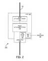
- FIG. 2is a block diagram of one high-level embodiment of a jack and media reading interface that are suitable for use as a jack in a wall plate device of the system of FIG. 1 .
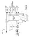
- FIG. 3is a block diagram illustrating one embodiment of a wall outlet that is suitable for use as a wall outlet device in the system of FIG. 1 .
- FIG. 4is a block diagram of an example host server communicatively coupled to a plurality of wall outlets in the system of FIG. 1 .
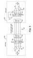
- FIG. 5is a block diagram of an example communication set-up between the host server and a wall outlet of FIG. 4 .
- FIG. 6is a circuit diagram of the example communication set-up between the host server and a wall outlet of FIG. 5 .
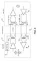
- FIG. 7is a circuit diagram of another example communication set-up between the host server and a wall outlet of FIG. 4 .
- FIG. 8is a circuit diagram of yet another example communication set-up between the host server and a wall outlet of FIG. 4 .
- FIG. 9is a block diagram illustrating another embodiment of a wall outlet that is suitable for use as a wall outlet device in the system of FIG. 1 .
- FIG. 10is a block diagram illustrating yet another embodiment of a wall outlet that is suitable for use as a wall outlet device in the system of FIG. 1 .
- FIG. 11is a block diagram illustrating still another embodiment of a wall outlet that is suitable for use as a wall outlet device in the system of FIG. 1 .
- FIG. 12is a block diagram illustrating another embodiment of a wall outlet that is suitable for use as a wall outlet device in the system of FIG. 1 .
- FIG. 13is a block diagram illustrating yet another embodiment of a wall outlet that is suitable for use as a wall outlet device in the system of FIG. 1 .
- FIG. 14is a block diagram illustrating still another embodiment of a wall outlet that is suitable for use as a wall outlet device in the system of FIG. 1 .
- FIG. 15is a block diagram of an example communication set-up between a network entity and a wall outlet device in the system of FIG. 1 using a hybrid cable.
- FIG. 16is a block diagram illustrating another embodiment of a wall outlet that is suitable for use as a wall outlet device in the system of FIG. 1 .
- FIG. 17is a block diagram illustrating another embodiment of a wall outlet that is suitable for use as a wall outlet device in the system of FIG. 1 .
- FIG. 1is a block diagram of one example of a system including physical layer management at wall plate devices.
- the systemis part of an IP network 126 which includes a plurality of network entities in a local area network (LAN) 104 .
- the example network entities shown in FIG. 1include a switch 160 (or other internetworking device such as a hub, bridge, router, or gateway), a patch panel 110 , a first and second wall plate device 130 , 150 , as well as a first and second end user device 106 a , 106 c .
- the first and second nodes 106 a , 106 care referred to herein as “end user devices” since they are outside of the core infrastructure (switch 160 , patch panel 110 , wall plate devices ( 130 , 150 ) of the LAN 104 and can be coupled to the core infrastructure by an end user (e.g., through a wall plate device 130 , 150 ).
- network entitiesinclude, for example, rack-mounted connector assemblies (such as patch panels, distribution units, and media converters for fiber and copper physical communication media), wall-mounted connector assemblies (such as boxes, jacks, wall plate devices (also referred to as “wall outlets”), and media converters for fiber and copper physical communication media), and inter-networking devices (such as switches, routers, hubs, repeaters, gateways, and access points).
- rack-mounted connector assembliessuch as patch panels, distribution units, and media converters for fiber and copper physical communication media
- wall-mounted connector assembliessuch as boxes, jacks, wall plate devices (also referred to as “wall outlets”), and media converters for fiber and copper physical communication media
- inter-networking devicessuch as switches, routers, hubs, repeaters, gateways, and access points.
- end user devicesinclude, without limitation, computers, peripherals (such as printers, copiers, storage devices, and scanners), IP telephones, end user routers, end user switches, access points (e.g., wireless), networked TVs, set top boxes, and other such end user devices.
- peripheralssuch as printers, copiers, storage devices, and scanners
- IP telephonessuch as printers, copiers, storage devices, and scanners
- end user routerssuch as printers, copiers, storage devices, and scanners
- access pointse.g., wireless
- networked TVsset top boxes, and other such end user devices.
- Each communication media 107is a cable comprising one or more communication paths.
- the one or more communication pathscan be formed by one or more fiber optics or one or more copper wires.
- the physical communication media 107can be implemented using a simplex cable, a hybrid cable, a multi-channel cable, etc.
- Some physical communication media 107such as media 107 d , 107 e , and 107 g , include a first connector terminating a first end of the one or more communication paths and a second connector terminating a second (opposite) end of the one or more communication paths.
- communication media 107can include a connector terminating a first end and a wall plate device 130 , 150 terminating a second (opposite) end.
- the connectorscan be corresponding passive optical connectors or an active optical module for converting between optical signals and electrical signals.
- the one or more communication pathsare copper wires
- connectorscan be a corresponding electrical connector.
- Some or all of the physical communication media 107is a connectorized media segment.
- a “connectorized” media segmentis a segment of physical communication media that includes a connector at at least one end of the segment. The connectors are used to facilitate the easy and repeated attachment and unattachment of the media segment 107 to a jack.
- Examples of connectorized media segmentsinclude CAT-5, 6, and 7 twisted-pair cables having modular connectors or plugs attached to both ends (in which case, the front connectors are implemented using compatible modular jacks) or optical cables having SC, LC, FC, LX.5, MTP, or MPO connectors (in which case, the front connectors are implemented using compatible SC, LC, FC, LX.5, MTP, or MPO connectors or adapters).
- the techniques described herecan be used with other types of connectors including, for example, BNC connectors, F connectors, DSX jacks and plugs, bantam jacks and plugs, and MPO and MTP multi-fiber connectors and adapters.
- Example physical communication media 107include duplex fiber optic cable including one or more optical fibers.
- the one or more optical fiberscan include single-mode or multi-mode fibers.
- the fiber optic cablecan include a simplex cable, duplex cable, 12-fiber cable, 24-fiber cable and other fiber optic cables (such as hybrid fiber/copper cables).
- Other example physical communication media 107include coaxial cable.
- Still other examplesinclude multiple-fiber cable including a multi-fiber connector (for example, a suitable MPO or MTP connector) at each end of such cable.
- the patch panel 110is used to cross connect various network entities of the local area network 104 , and comprises a set of port (not shown). Each port is associated with a respective jack on the front face of the patch panel 107 into which a RJ-45 connector of a communication media 107 can be inserted. Various ports of the patch panel 107 can be connected to ports of the switch 160 by connecting one or more communication mediums 107 g between the front jacks of the patch panel 107 and jacks of the switch 160 .
- Each portis also associated with a respective rear termination point at which a horizontal run of a communication media 107 can be terminated.
- Each portis configured to communicatively couple the jack associated with that port (and any communication media 107 inserted therein) to the respective termination point (and any horizontal run of communication media 107 terminated thereat). In this way, a patch cord inserted into the front jack of the port can be connected to the corresponding horizontal run of twisted-pair cabling terminated at the corresponding rear termination point.
- each horizontal runterminates at its other end at a wall plate device 130 , 150 .
- Two types of wall plate devicesare shown in FIG. 1 .
- the distribution wall plate device 130is coupled to the patch panel 107 with the communication media 107 a (e.g., a CAT-5 or CAT-6 cable).
- the distribution wall plate device 130includes a termination point 132 at which a horizontal run of the communication media 107 a can be terminated.
- a first connector of the communication media 107 ais connected to a first jack of the patch panel 107 and a second end of the communication media 107 a is attached to the termination point of the distribution wall plate device 130 .
- the distribution wall plate device 130also includes a plurality of jacks 134 (for example, RJ-45 jacks) and an ETHERNET hub or switch 136 .
- the termination point 132 for the horizontal run and each of the jacks 134are coupled to a respective port of the ETHERNET hub or switch 136 .
- each of the jacks 134is communicatively coupled to the horizontal run terminated at the termination point 132 , and the connectivity provided over the horizontal run can be shared by devices connected to the jacks 134 .
- the distribution wall plate device 130also includes a suitable power supply or interface (not shown) for providing power to the ETHERNET hub or switch 136 .
- Examples of ways of providing power to the ETHERNET hub or switch 136include using Power-Over-ETHERNET technology to provide power over the horizontal run of the communication media 107 a and/or over one or more communication mediums 107 d connected to the jacks 134 .
- Powercan also be provided by connecting the distribution wall plate device 130 to a conventional AC mains power outlet using an external or internal power adapter.
- An end user device 106 a of the network 104is coupled to other network entities in the local area network 104 by connecting one end of a physical communication media 107 d (e.g., a CAT-5 or CAT-6 cable) to the end user device 106 a and the other end of the communication media 107 d to one of the jacks 134 of the distribution wall plate device 130 .
- the end user device 106 acomprises a wireless access point, however, any device capable of connecting to the jack 134 and communicating over the network 104 can be used.
- the wireless access point 106 acan be wireless coupled to another device 102 .
- the passive wall plate device 150includes a termination point 124 for a horizontal run of the communication media 107 c and a corresponding jack 154 .
- the passive wall plate device 150is coupled to the patch panel 107 with the communication media 107 c (e.g., a CAT-5 or CAT-6 cable).
- a first connector at a first end of the communication media 107 cis connected to a first jack of the patch panel 107 and a second end of the communication media 107 c is attached to a termination point 132 of the passive wall plate device 150 .
- Each conductor in the horizontal run of twisted-pair cabling ( 107 c )is electrically connected to a corresponding conductor in the jack 154 .
- the jack 154is communicatively coupled to the horizontal run terminated at the termination point 124 , and the connectivity provided over the horizontal run can be shared by any devices connected to the jack 154 .
- an end user device 106 cis connected to the local area network 104 by connecting one end of a communication media 107 e (e.g., a CAT-5 or CAT-6 cable) to the end user device 106 c and the other end of the communication media 107 e to the jack 154 of the passive wall plate device 150 .
- a communication media 107 ee.g., a CAT-5 or CAT-6 cable
- At least some of the network entitiesare designed for use with segments of physical communication media 107 that have identifier and attribute information (also referred to herein as “PLM information”) stored in or on them.
- PLM informationalso referred to herein as “PLM information”.
- the identifier and attribute informationis stored in or on the segment of physical communication media 107 in a manner that enables the stored information, when the segment is attached to a jack ( 134 , 154 ), to be read by a programmable processor associated with the network entity.
- Examples of PLM information that can be stored in or on a segment of physical communication media 107include, without limitation, an identifier that uniquely identifies that particular segment of physical communication media 107 (similar to an ETHERNET Media Access Control (MAC) address but associated with the physical communication media 107 and/or connector attached to the physical communication media 107 ), a part number, a plug or other connector type, a cable or fiber type and length, a serial number, a cable polarity, a date of manufacture, a manufacturing lot number, information about one or more visual attributes of physical communication media 107 or a connector attached to the physical communication media 107 (such as information about the color or shape of the physical communication media 107 or connector or an image of the physical communication media 107 or connector), and other information used by an Enterprise Resource Planning (ERP) system or inventory control system.
- PLM informationcan also include testing or media quality or performance information which, for example, can be the results of testing that is performed when a particular segment of media 107 is manufactured. In other embodiments, alternate or additional data is stored
- the PLM information stored in or on the segment of physical communication media 107can be updated.
- the PLM information stored in or on the segment of physical communication media 107can be updated to include the results of testing that is performed when a segment of physical media 107 is installed or otherwise checked.
- such testing informationis supplied to an aggregation point 124 and stored in a data store maintained by the aggregation point 124 .
- the PLM information stored in or on the segment of physical communication media 107includes a count of the number of times that a connector attached to a segment of physical communication media 107 has been inserted into jack ( 134 , 154 ).
- the count stored in or on the segment of physical communication media 107is updated each time the connector 102 is inserted into jack ( 134 , 154 ).
- This insertion count valuecan be used, for example, for warranty purposes (for example, to determine if the connector has been inserted more than the number of times specified in the warranty) or for security purposes (for example, to detect unauthorized insertions of the physical communication media 107 ).
- each of the jacks ( 134 , 154 ) of the network entities 101comprises a respective media reading interface via which the respective programmable processor is able to determine if a physical communication media segment 107 is attached to that jack ( 134 , 154 ) and, if one is, to read the identifier and attribute information (PLM information) stored in or on the attached segment (if such information is stored therein or thereon).
- the programmable processor associated with each network entityis communicatively coupled to each of the media reading interfaces using a suitable bus or other interconnect.
- Each programmable processoris configured to execute software or firmware that causes the programmable processor to carry out various functions described below.
- Each programmable processoralso includes suitable memory that is coupled to the programmable processor for storing program instructions and data.
- the programmable processordetermines if a physical communication media segment 107 is attached to a jack ( 134 , 154 ) with which that processor is associated and, if one is, to read the identifier and attribute information (PLM information) stored in or on the attached physical communication media segment 107 (if the segment 107 includes such information stored therein or thereon) using the associated media reading interface.
- PLM informationidentifier and attribute information
- Each programmable processoris also configured to communicate physical layer information to devices that are coupled to the IP network 126 .
- the physical layer informationincludes information about the network entities associated with that programmable processor (also referred to here as “device information”) as well as information about any segments of physical media 107 attached to the jacks ( 134 , 154 ) of those network entities (also referred to here as “PLM information”)
- the device informationincludes, for example, an identifier for each network entity, a type identifier that identifies the network entity's type, and jack priority information that associates a priority level with each jack.
- the PLM informationincludes identity and attribute information that the programmable processor has read from attached physical media segments 107 that have identifier and attribute information stored in or on it.
- the PLImay also include information about physical communication media 107 that does not have identifier or attribute information stored in or on it. This latter type of PLI can be manually input at the time the associated physical media segments 107 are attached to the network entity (for example, using a management application executing on the programmable processor that enables a user to configure and monitor the network entity).
- the systemincludes functionality that enables the physical layer information that the network entities capture to be used by application-layer functionality outside of traditional physical-layer management application domain. That is, the physical layer information is not retained in a PLM “island” used only for PLM purposes but is instead made available to other applications.
- the systemincludes an aggregation point 124 that is communicatively coupled to the network entities via the IP network 126 .
- the aggregation point 124includes functionality that obtains physical layer information from the network entities (and other devices) and stores the physical layer information in a data store.
- the aggregation point 124can be used to receive physical layer information from various types of network entities that have functionality for automatically reading information stored in or on the segment of physical communication media 107 . Examples of such network entities are noted above. Also, the aggregation point 124 and aggregation functionality can also be used to receive physical layer information from other types of devices that have functionality for automatically reading information stored in or on the segment of physical communication media 107 . Examples of such devices include end-user devices—such as computers, peripherals (such as printers, copiers, storage devices, and scanners), and IP telephones—that include functionality for automatically reading information stored in or on the segment of physical communication media.
- end-user devicessuch as computers, peripherals (such as printers, copiers, storage devices, and scanners), and IP telephones—that include functionality for automatically reading information stored in or on the segment of physical communication media.
- the aggregation point 124can also be used to obtain other types of physical layer information.
- the aggregation point 124also obtains information about physical communication media segments 107 that is not otherwise automatically communicated to an aggregation point 124 .
- Such informationis information about physical communication media segments that are connected to devices that are not be able to read media information that is stored in or on the media segments that are attached to their jacks and/or that are not able to communicate such information to the aggregation point 124 (for example, because such devices do not include such functionality, because such devices are used with media segments that do not have media information stored in or on them, and/or because bandwidth is not available for communicating such information to the aggregation point 124 ).
- the informationcan include, for example, information about the devices themselves (such as the devices' MAC addresses and IP addresses if assigned to such devices), information indicating which jacks of the devices are connected to which jacks of other devices in the network (for example, other network entities), and information about the physical media attached to the jacks of the devices.
- This informationcan be provided to the aggregation point 124 , for example, by manually entering such information into a file (such as a spreadsheet) and then uploading the file to the aggregation point 124 (for example, using a web browser) in connection with the initial installation of each of the various items.
- Such informationcan also, for example, be directly entered using a user interface provided by the aggregation point 124 (for example, using a web browser).
- the aggregation point 124can also obtain information about the layout of the building or buildings in which the network is deployed, as well as information indicating where each network entity and physical media segment 107 is located within the building. This information can be, for example, manually entered and verified (for example, using a web browser) in connection with the initial installation of each of the various items.
- location informationincludes an X, Y, and Z location for each jack or other termination point for each physical communication media segment (for example, X, Y, and Z location information of the type specified in the ANSI/TIA/EIA 606-A Standard (Administration Standard For The Commercial Telecommunications Infrastructure)).
- the aggregation point 124can obtain and maintain testing, media quality, or performance information relating to the various segments of physical communication media that exist in the network.
- the testing, media quality, or performance informationcan be results of testing that is performed when a particular segment of media is manufactured and/or when testing is performed when a particular segment of media is installed or otherwise checked.
- the aggregation point 124also includes functionality that provides an interface for external devices or entities to access the physical layer information maintained by the aggregation point 124 . This access can include retrieving information from the aggregation point 124 as well as supplying information to the aggregation point 124 .
- the aggregation point 124is implemented as “middleware” that is able to provide such external devices and entities with transparent and convenient access to the PLI.
- the aggregation point 124aggregates PLI from the relevant devices on the IP network 126 and provides external devices and entities with access to such PLI, the external devices and entities do not need to individually interact with all of the devices in the IP network 126 that provide PLI, nor do such devices need to have the capacity to respond to requests from such external devices and entities.
- the aggregation point 124in the embodiment shown in FIG. 1 , implements an application programming interface (API) by which application-layer functionality can gain access to the physical layer information maintained by the aggregation point 124 using a software development kit (SDK) that describes and documents the API.
- APIapplication programming interface
- SDKsoftware development kit
- an inter-networking deviceis a type of network entity and can be configured to read PLM information that is stored in or on the segments of physical media 107 that are attached to its jacks and to communicate the PLM information it reads from the attached segments of media 107 (as well as information about the inter-networking device itself) to the aggregation point 124 like any other network entity described here.
- the aggregation point 124can be implemented on a standalone network node (for example, a standalone computer running appropriate software) or can be integrated along with other network functionality (for example, integrated with an element management system or network management system or other network server or network element). Moreover, the functionality of the aggregation point 124 can be distribute across many nodes and devices in the network and/or implemented, for example, in a hierarchical manner (for example, with many levels of aggregation points).
- the aggregation point 124 and the network entitiesare configured so that the aggregation point 124 can automatically discover and connect with the network entities that provide PLI to an aggregation point 124 that are on the network 126 .
- an aggregation point 124is able to automatically discover the network entities and start aggregating physical layer information for that network entity without requiring the person installing the network entity to have knowledge of the aggregation points 124 that are on the IP network 126 .
- the aggregation point 124when an aggregation point 124 is coupled to the IP network 126 , the aggregation point 124 is able to automatically discover and interact with devices that are capable of providing PLI to an aggregation point without requiring the person installing the aggregation point 124 to have knowledge of the devices that are on the IP network 126 .
- the physical-layer information resources described herecan be easily integrated into the IP network 126 .
- the aggregation point 124can aggregate the PLI from the network entities and physical communication media to associate jacks of network entities (e.g., patch panels) with physical communication media.
- the PLIcan be used to associate a given jack of a network entity with a give physical communication media and/or a particular connector of the physical communication media.
- Aggregating the PLIcan include aggregating multiple such associations to determine physical layer connections between devices.
- the IP network 126can include one or more local area networks and/or wide area networks (including for example the Internet). As a result, the aggregation point 124 need not be located at the same site as the network entities.
- IP networking techniquescan be used in deploying the system of FIG. 1 .
- conventional security protocolscan be used to secure communications if they are communicated over a public or otherwise unsecure communication channel (such as the Internet or over a wireless communication link).
- each network entity, each jack ( 134 , 154 ) of each network entity, and each media segment 107is individually addressable.
- IP addressesare used to individually address each network entity
- a virtual private network (VPN) dedicated for use with the various network entitiescan be used to segregate the IP addresses used for the network entities from the main IP address space that is used in the IP network 126 .
- VPNvirtual private network
- the systemalso supports conventional physical layer management (PLM) operations such as the tracking of moves, adds, and changes of the segments of physical media that are attached to the jacks ( 134 , 154 ) of the network entities and providing assistance with carrying out moves, adds, and changes.
- PLMphysical layer management
- PLI provided by the aggregation point 124can be used to improve upon conventional “guided MAC” processes. For example, information about the location of the jack ( 134 , 154 ) and the visual appearance (for example, the color or shape) of the relevant physical media segment 107 (or connector attached thereto) can be communicated to a technician to assist the technician in carrying out a move, add, or change.
- This informationcan be communicated to a computer or smartphone used by the technician.
- the PLI functionality that resides in the systemcan also be used to verify that a particular MAC was properly carried out by checking that the expected physical media segment is located in the expected jack ( 134 , 154 ). If that is not the case, an alert can be sent to the technician so that the technician can correct the issue.
- the PLM functionality included in the systemcan also support conventional techniques for guiding the technician in carrying out a MAC (for example, by illuminating one or more light emitting diodes (LEDs) to direct a technician to a particular network entity and/or to a particular jack ( 134 , 154 ) or by displaying messages on a liquid crystal display (LCD) included on or near the network entity.
- a MACfor example, by illuminating one or more light emitting diodes (LEDs) to direct a technician to a particular network entity and/or to a particular jack ( 134 , 154 ) or by displaying messages on a liquid crystal display (LCD) included on or near the network entity.
- Other PLM functionsinclude keeping historical logs about the media 107 connected to the network entity.
- the techniques described here for reading PLM information stored in or on a segment of physical communication media 107can be used in one or more end user devices of the network.
- computerssuch as, laptops, servers, desktop computers, or special-purpose computing devices such as IP telephones, IP multi-media appliances, and storage devices
- computerscan be configured to read PLM information that is stored in or on the segments of physical communication media 107 that are attached to their jacks and to communicate the media information the read from the attached segments of media 107 (as well as information about the devices themselves) to an aggregation point 124 as described here.
- the wall plate devices 130 , 150can communicate PLI with the aggregation point 124 along with “non-service” network traffic over the communication media 107 a and 107 c respectively.
- “non-service” network trafficis defined with respect to the wall plate devices ( 130 , 150 ), such that network traffic destined for or originating from an end user device ( 106 a , 106 c ) is “non-service” network traffic.
- the wall plate devices 130 , 150can communicate PLI through a host server 402 .
- the host server 402is communicatively coupled to each of the wall plate devices 130 , 150 using appropriate physical communication media 308 .
- the host server 402can be coupled to the LAN 104 by connecting the host server 402 to a corresponding communication media 308 connected on the other end to a network entity (e.g., patch panel 110 ).
- a network entitye.g., patch panel 110
- the physical communication media 308 used for communication with the host server 402is distinct from the communication media 107 used for “non-service” network traffic.
- Physical communication media 308can be the same or a different type of communication media as the communication media 107 .
- physical communication media 308can include CAT-5, 6, and 7 twisted-pair cables, optical cables, or coaxial cable.
- the host server 402can be configured to communicate with the aggregation point 124 over the LAN 104 and, more broadly, the IP network 126 .
- the host server 402can communicate PLI to/from the aggregation point 124 and also communicate PLI to/from each wall outlet device 130 , 150 .
- the PLI from each wall outlet device 130 , 150can be provided to the aggregation point 124 and the aggregation point 124 can provide information and/or commands to each wall outlet device 130 , 150 .
- one or more of the wall outlet devices 130 , 150can communicative wirelessly as described in more detail below.
- FIG. 2is a block diagram of one high-level embodiment of a jack 200 and media reading interface 108 that are suitable for use as a jack 134 , 154 in a wall plate device 130 , 150 of FIG. 1 .
- Each jack 200comprises a first attachment point 206 and a second attachment point 208 .
- the first attachment point 206is used to attach one or more communication paths 210 to the jack 200
- the second attachment point 208is used to attach a segment of physical communication media 107 to the jack 200 .
- the one or more communication paths 210can be part of the wall outlet device 130 , 150 and connected to appropriate components within the wall outlet device 130 , 150 or can be part of another communication media 107 that is connected to another network entity (e.g., patch panel 110 ) at its other end.
- another network entitye.g., patch panel 110
- the first attachment point 206is located near the rear of the jack 200 .
- the first attachment point 206is also referred to here as the “rear attachment point” 206 .
- the rear attachment point 206is configured to attach the one or more communication paths 210 to the jack 200 in a semi-permanent manner.
- a semi-permanent attachmentis one that is designed to be changed relatively infrequently, if ever. This is also referred to sometimes as a “one-time” connection.
- suitable rear attachment points 206include punch-down blocks (in the case of copper physical media) and fiber adapters, fiber splice points, and fiber termination points (in the case of optical physical media).
- the second attachment point 208is located near the front of the jack 200 .
- the second attachment point 208is also referred to here as the “front attachment point” 208 .
- the front attachment point 208 for each jack 200is designed for use with “connectorized” media segments 107 that have identifier and attribute information stored in or on them.
- a “connectorized” media segmentis a segment of physical communication media that includes a connector 102 at at least one end of the segment.
- the front attachment point 208is implemented using a suitable connector or adapter that mates with the corresponding connector 102 on the end of the media segment 107 .
- the connector 102is used to facilitate the easy and repeated attachment and unattachment of the media segment 107 to the jack 200 .
- Examples of connectorized media segmentsinclude CAT-5, 6, and 7 twisted-pair cables having modular connectors or plugs attached to both ends (in which case, the front attachment point 208 is implemented using compatible modular plugs) or optical cables having SC, LC, FC, LX.5, MTP, or MPO connectors (in which case, the front attachment point 208 is implemented using compatible SC, LC, FC, LX.5, MTP, or MPO connectors or adapters).
- the techniques described herecan be used with other types of connectors including, for example, BNC connectors, F connectors, DSX jacks and plugs, bantam jacks and plugs, and MPO and MTP multi-fiber connectors and adapters.
- Each jack 200communicatively couples the respective rear attachment point 206 to the respective front attachment point 208 .
- one or more communication paths 210 attached to the respective rear attachment point 206are communicatively coupled to any media segment 107 attached to the respective front attachment point 208 .
- each jack 200is designed for use with one or more communication paths 107 and a media segment 107 that comprise the same type of communication path(s), in which case each jack 200 communicatively couples the one or more communication paths 210 attached to the respective rear attachment point 206 to any media segment 107 attached to the respective front attachment point 208 at the physical layer level without any media conversion.
- each jack 200communicatively couples the one or more communication paths 210 attached to the respective rear attachment point 206 to any media segment 107 attached to the respective front attachment point 208 in other ways (for example, using a media converter if the rear one or more communication paths 210 and the media segment 107 comprise different types of communication paths).
- the jack 200is configured for use with media segments 107 that include a PLM interface 216 that, when the corresponding connector 214 is inserted into (or otherwise attached to) a front attachment point 208 of the jack 200 , communicatively couples a storage device or other component(s) to a corresponding media reading interface 108 so that the associated programmable processor 106 can obtain PLM information from the storage device or other component(s).
- each connector 102itself houses the storage device or other component(s) and the PLM interface can be implemented by incorporating appropriate electrical contacts in the connector 102 .
- the storage device and other component(s)are housed within a housing that is separate from the connector 102 .
- the housingis configured so that it can be snapped onto the media segment 107 or the connector 102 , with the PLM interface 216 positioned relative to the connector 102 so that the PLM interface 216 will properly mate with the media reading interface 108 when the connector 102 is inserted into (or otherwise attached to) the front attachment point 208 .
- a four-line PLM interfaceis used, where the interface includes a single data line for reading and writing data, a power line for providing power to the storage device, a ground line for providing a ground level, and an extra line reserved for future use.
- a storage device that supports the UNI/O bus protocolis used, where the UNI/O bus protocol is used for communicating over the single data lead.
- QUAREOTTM family of physical layer management productsthat are commercially available from TE Connectivity.
- FIG. 3is a diagram illustrating one embodiment of wall outlet 300 that is suitable for use as a wall outlet device 130 , 150 in the system 100 of FIG. 1 .
- Wall outlet 300can have one or more jacks 200 configured to mate with one or more connectors of one or more physical communication media 107 .
- the wall outlet 300includes one jack 200 for mating with an optical cable and three jacks 200 for mating with a CAT-5 or CAT-6 cable, however other numbers and types of jacks can be used.
- the wall outlet 300terminates a horizontal run of corresponding media 107 (e.g., multi-mode optical cable, CAT-5, CAT-6 cables) for each jack 200 .
- the wall outlet 300is a passive wall outlet 150 such that each jack 200 terminates a horizontal run of a corresponding media 107 .
- the horizontal run of the corresponding media 107can be terminated at a switch (not shown) in the wall outlet 300 .
- the wall outlet 300terminates at least one run of a passive optical cable and at least one run of a twisted pair cable (e.g., CAT-5 or CAT-6 cable).
- the wall outlet 300also includes an active module 301 that comprises a programmable processor 302 that is coupled to a storage device.
- the programmable processor 302can include any suitable programmable processor, such as a microprocessor (e.g., an 8-bit microprocessor).
- the storage devicecan include, for example, an Electrically Erasable Programmable Read-Only Memory (EEPROM) or other non-volatile memory device.
- EEPROMElectrically Erasable Programmable Read-Only Memory
- the programmable processor 302 and the storage devicecan be the same die, on separate dies, or can be incorporated into a chip scale package.
- the programmable processor 302can be configured to communicate with a storage device or other component in a communication media 107 connected to a jack 200 over a media reading interface 108 of the respective jack 200 .
- the media reading interface 108while the corresponding connector is inserted into a front attachment point 208 of a jack 200 , communicatively couples the programmable processor 302 to the corresponding PLM interface 216 so that the programmable processor 302 can access the storage device or other entity associated with the connector of the communication media 107 .
- the programmable processor 302is configured to obtain PLM information from communication media 107 connected (mated) with jacks 200 and send the PLM information to the host server 402 .
- the programmable processor 302can also be configured to send PLI regarding itself to the host server 402 as well as receiving information from the host server 402 .
- the active module 301can include a signaling circuit 304 , such as an RS-422 signaling circuit, coupled via appropriate pulse transformers 306 to a communication media 308 which is connected at the other end to the host server 402 .
- the signaling circuit 304can communicate with the host server 402 using a serial communication scheme over the communicate media 308 .
- the active module 301also includes a power supply unit 310 that is coupled to the transformer 306 for recovering power from the signals on the communication media 308 , and for supplying such recovered power to the programmable processor 302 and signaling circuit 304 as described in more detail below.
- the active module 301can also include a local input/output port 312 such as a UNIO port.
- the wall outlet 300enables the non-service traffic from all of its ports (jacks 200 ) to travel on paths (e.g., communication media 107 ) that are distinct from the paths of the service traffic (e.g., communication media 308 ).
- FIG. 4is an example of the host server 402 communicatively coupled to a plurality of wall outlets 300 via a plurality of communication media 308 .
- the host server 402can be configured to relay communications between the plurality of wall outlets 300 and the aggregation point 124 .
- the communications between the aggregation point 124 and the host server 402can be in the form of IP communications sent, for example, via network switch 160 through IP network 126 to the aggregation point 124 .
- the host server 402can include a multiplex module 404 (e.g., a RS-422 MUX) to multiplex/demultiplex signals between the host server 402 and the plurality of wall outlets 300 .
- a programmable processor 406 in the host server 402can transmit and receive signals from the plurality of wall outlets 300 via the multiplex module 404 .
- the programmable processor 406can also communicate with the aggregation point 124 via the switch 160 and IP network 126 .
- the programmable processor 402 in the host server 402can act as a master and direct control of each slave processor 302 in a wall outlet 300 . Accordingly, the master processor 406 can instruct each slave processor 302 to obtain PLM information from communication media 107 connected to jacks 200 of their respective wall outlets 300 .
- the host server 404can also include a power interface 408 that can be coupled to a suitable power source 410 (e.g., DC power source).
- the multiplex module 404can be coupled to the power interface 408 to simplex power and data over the communication media 308 to each wall outlet 300 . That power can be recovered from the communication media 208 by the power supply unit 310 in each wall outlet 300 .
- conductorse.g., a power cable
- a power cablethat are separate from the communication media 108 can be used to provide power to each wall outlet 300 .
- each communication media 308can comprise a CAT-5 or CAT-6 cable and the host server 402 and each wall outlet 300 can implement serial communication (e.g., RS-422) therebetween using 1, 2, or 4 pairs (e.g., twisted pairs) of communication lines.
- serial communicatione.g., RS-422
- FIGS. 5 and 6illustrate an example where 2 twisted pairs in a communication media 308 are used between the host server 402 and a wall outlet 300 .
- the host server 402can include suitable amplifiers 502 for transmitting and receiving signals over the respective twisted pairs.
- the signaling circuit 304 in the wall outlet 300can also include suitable amplifiers 504 for transmitting and receiving signals over the respective twisted pairs.
- the host server 402can also include a first pulse transformer 506 coupled across a first twisted pair used for transmitting signals from the host server 402 to the wall outlet 300 .
- the first pulse transformer 506can also be coupled to DC power (e.g., from the power interface 408 ) for providing a DC power average on the first twisted pair.
- the host server 402can also include a second pulse transformer 506 for providing DC ground average on the second twisted pair.
- the wall outlet 300can include a corresponding first pulse transformer 308 and second pulse transformer 308 for recovering the DC power as a difference between the DC power in the first twisted pair and the DC power in the second twisted pair. This power can be recovered by the power supply unit 310 and provided to the programmable processor 302 and signaling circuit 304 .
- the host server 402 and the wall outlet 300can also include suitable jacks 510 , 512 for connecting of the communication media 108 .
- FIG. 7illustrates an example where 1 twisted pair in a communication media 308 is used between the host server 402 and a wall outlet 300 .
- 1 twisted pairWith 1 twisted pair, half duplex communication is implemented using a differential transmission method. Accordingly, transmissions to and from the host server 402 and the wall outlet 300 occur over the same twisted pair.
- the host server 402 and the wall outlet 300include respective amplifiers 702 for transmitting and receiving signals over the twisted pair. In this example, however, the transmit and receive amplifiers 702 , 703 are both coupled to the (same) twisted pair.
- a single pulse transformer 704is used at host server 402 to couple DC power and ground onto the twisted pair.
- a single pulse transformer 705is used at the wall outlet 300 to recover the DC power from the twisted pair.
- FIG. 8illustrates an example where 4 twisted pairs in a communication media 308 are used between the host server 402 and a wall outlet 300 .
- two of the twisted pairsare used for full duplex communication using (e.g., differential transmission) between the host server 402 and the wall outlet 300 .
- the other two twisted pairsare used to provide DC power from the host server 402 to the wall outlet 300 .
- the transmit and receive amplifiers 802 of the host server 402are coupled to a first twisted pair and a second twisted pair respectively.
- the transmit and receive amplifiers 803 of the wall outlet 300are couple to the second twisted pair and the first twisted pair respectively.
- a first transformer 804 in the host server 402is coupled to a third twisted pair and DC power to provide DC power on the third twisted pair.
- a second transformer 805 in the host server 402is coupled to the fourth twisted pair to provide DC ground over the fourth twisted pair.
- a first and second transformers 806 in the wall outlet 300are coupled to the third and fourth twisted pair to recover the DC power therefrom.
- Example 2the wall outlet 900 that is used differs from the wall outlet 300 used in Example 1.
- the wall outlet 900 that is used in Example 2is shown in FIG. 9 . It is to be understood that, in practice, wall outlet 300 and wall outlet 900 may be used within the same network.
- FIG. 9illustrates another example of a wall outlet 900 that is suitable for use as a wall outlet device 130 , 150 in the system 100 of FIG. 1 .
- Wall outlet 900can include one or more jacks 200 configured to mate with one or more connectors of one or more physical communication media 107 .
- the wall outlet 900includes one jack 200 for mating with an optical cable and three jacks 200 for mating with a CAT-5 or CAT-6 cable, however other numbers and types of jacks can be used.
- the wall outlet 900terminates a horizontal run of corresponding media 107 (e.g., multi-mode optical cable, CAT-5, CAT-6 cables) for each jack 200 .
- corresponding media 107e.g., multi-mode optical cable, CAT-5, CAT-6 cables
- the wall outlet 300is a partially passive wall outlet such that three of the jacks 200 terminate a horizontal run of a corresponding media 107 .
- One horizontal run of corresponding media 107is terminated at an active module 901 in the wall outlet 300 .
- the wall outlet 900terminates at least one run of a passive optical cable and at least one run of a twisted pair cable (e.g., CAT-5 or CAT-6 cable).
- the active module 901comprises a programmable processor 302 that is coupled to a storage device.
- the programmable processor 302can include any suitable programmable processor, such as a microprocessor (e.g., an 8-bit microprocessor).
- the storage devicecan include, for example, an Electrically Erasable Programmable Read-Only Memory (EEPROM) or other non-volatile memory device.
- EEPROMElectrically Erasable Programmable Read-Only Memory
- the programmable processor 302 and the storage devicecan be the same die, on separate dies, or can be incorporated into a chip scale package.
- the programmable processor 302can be configured to communicate with a storage device or other component in a communication media 107 connected to a jack 200 over a media reading interface 108 of the respective jack 200 .
- the media reading interface 108while the corresponding connector is inserted into a front connector of a jack 200 , communicatively couples the programmable processor 302 to the corresponding PLM interface 216 so that the programmable processor 302 can access the storage device or other entity associated with the connector of the communication media 107 .
- the programmable processor 302is configured to obtain PLM information from communication media 107 connected (mated) with jacks 200 and send the PLM information to the aggregation point 124 .
- the programmable processor 302can also be configured to send PLI regarding itself to the aggregation point 124 as well as receiving information from the aggregation point 124 .
- the programmable processor 302can be configured to communicate with a switch 902 within the active module 901 .
- the switch 902can be coupled to the programmable processor 302 and can also be coupled to a jack 200 for connection of physical communication media 107 to an end user device 106 and to another jack 200 for connection of a horizontal run of physical communication media 107 to a network entity (e.g., patch panel 110 ).
- the switch 902can function to relay information between the network entity (e.g., switch 160 ) and an end user device 106 connected to the jack 200 , and between the network entity (e.g., switch 160 ) and the programmable processor 302 .
- the programmable processor 302can use this connection with the switch 902 to communicate with the aggregation point 124 .
- the programmable processor 302can communicate PLI to the switch 902 which can provide the PLI over the network 104 to the aggregation point 124 .
- this configurationenables communication between the aggregation point 124 and the programmable processor 302 to be implemented over the same communication media 107 that are used for “non-service” network traffic. Accordingly, no additional communication media 308 need be run.
- this configurationcan be easily retrofit into existing networks due to the lack of additional components required outside of the wall outlet 900 .
- the wall outlet 900enables the non-service traffic from all of its ports (jacks 200 ), except for one (or more) port(s), to travel on paths (e.g., communication medium 107 ) that are distinct from the paths of the service traffic (e.g., communication mediums 308 ).
- the active module 901can also includes a power supply unit 310 to recover power from the communication media 107 , such as, for example, by power over Ethernet (PoE) for powering of the programmable processor 302 and switch 902 .
- PoEpower over Ethernet
- Line powercan also be used as an option in non-PoE installations.
- FIG. 10illustrates another example of a wall outlet 1000 that is suitable for use as a wall outlet device 130 , 150 in the system 100 of FIG. 1 .
- the wall outlet 1000is similar to the wall outlet 900 except, here, the communications to the aggregation point 124 are over a communication media 308 that is distinct from the communication media 107 used for “non-service” network traffic.
- Wall outlet 1000can include one or more jacks 200 configured to mate with one or more connectors of one or more physical communication media 107 .
- the wall outlet 1000includes one jack 200 for mating with an optical cable and three jacks 200 for mating with a CAT-5 or CAT-6 cable, however other numbers and types can jacks can be used.
- the wall outlet 1000terminates a horizontal run of corresponding media 107 (e.g., multi-mode optical cable, CAT-5, CAT-6 cables) for each jack 200 .
- corresponding media 107e.g., multi-mode optical cable, CAT-5, CAT-6 cables
- the wall outlet 100is a passive wall outlet 150 such that each jack 200 terminates a horizontal run of a corresponding media 107 .
- the horizontal run of the corresponding media 107can be terminated at a switch (not shown) in the wall outlet 1000 .
- the wall outlet 1000terminates at least one run of a passive optical cable and at least one run of a twisted pair cable (e.g., CAT-5 or CAT-6 cable).
- the wall outlet 1000includes an active module 1001 comprising a programmable processor 302 that is coupled to a storage device.
- the programmable processor 302can include any suitable programmable processor, such as a microprocessor (e.g., an 8-bit microprocessor).
- the storage devicecan include, for example, an Electrically Erasable Programmable Read-Only Memory (EEPROM) or other non-volatile memory device.
- EEPROMElectrically Erasable Programmable Read-Only Memory
- the programmable processor 302 and the storage devicecan be the same die, on separate dies, or can be incorporated into a chip scale package.
- the programmable processor 302can be configured to communicate with a storage device or other component in a communication media 107 connected to a jack 200 over a media reading interface 108 of the respective jack 200 .
- the media reading interface 108while the corresponding connector is inserted into a front connector of a jack 200 , communicatively couples the programmable processor 302 to the corresponding PLM interface 216 so that the programmable processor 302 can access the storage device or other entity associated with the connector of the communication media 107 .
- the programmable processor 302is configured to obtain PLM information from communication media 107 connected (mated) with jacks 200 and send the PLM information to the aggregation point 124 .
- the programmable processor 302can also be configured to send PLI regarding itself to the aggregation point 124 as well as receiving information from the aggregation point 124 .
- the programmable processor 302can be configured to communicate with a media access control/physical layer (MAC/PHY) device 1002 within the wall outlet 100 .
- the MAC/PHY 1002can be coupled to the programmable processor 302 and can also be coupled to a jack 200 for connection of physical communication media 308 to a network entity (e.g., patch panel 110 ). Accordingly, the MAC/PHY 1002 can translate and forward information between the programmable processor 302 and the network entity.
- the programmable processor 302can use this connection with the MAC/PHY 1002 to communicate with the aggregation point 124 .
- the programmable processor 302can communicate PLI to the MAC/PHY 1002 which can provide the PLI over the network 104 to the aggregation point 124 .
- the wall outlet 1000enables the non-service traffic from all of its ports (jacks 200 ) to travel on paths (e.g., communication media 107 ) that are distinct from the paths of the service traffic (e.g., communication media 308 ).
- the active module 1001can also include a power supply unit 310 to recover power from the communication media 308 , such as, for example, by power over Ethernet (PoE) for powering of the programmable processor 302 and MAC/PHY 1002 .
- PoEpower over Ethernet
- Line powercan also be used as an option in non-PoE installations.
- FIG. 11illustrates another example of a wall outlet 1100 that is suitable for use as a wall outlet 130 , 150 , in the system 100 of FIG. 1 .
- the wall outlet 1100is similar to the wall outlet 1000 except, here, a switch 1102 in the wall outlet 1100 forms a LAN that is used to connect to multiple (e.g., all) jacks 200 of the wall outlet.
- Wall outlet 1100can include one or more jacks 200 configured to mate with one or more connectors of one or more physical communication media 107 .
- the wall outlet 1100includes one jack 200 for mating with an optical cable and three jacks 200 for mating with a CAT-5 or CAT-6 cable, however other numbers and types of jacks can be used.
- a first jack 200 for the optical cableterminates a horizontal run of the corresponding passive optical cable (e.g., multi-mode optical cable).
- the wall outlet 1100also provides a rear jack 200 for connecting to a horizontal run of a CAT-5 or CAT-6 cable to couple the switch 1102 to a network device (e.g., patch panel 110 ).
- the wall outlet 1100also comprises a programmable processor 302 that is coupled to a storage device.
- the programmable processor 302can include any suitable programmable processor, such as a microprocessor (e.g., an 8-bit microprocessor).
- the storage devicecan include, for example, an Electrically Erasable Programmable Read-Only Memory (EEPROM) or other non-volatile memory device.
- EEPROMElectrically Erasable Programmable Read-Only Memory
- the programmable processor 302 and the storage devicecan be the same die, on separate dies, or can be incorporated into a chip scale package.
- the programmable processor 302can be configured to communicate with a storage device or other component in a communication media 107 connected to a jack 200 over a media reading interface 108 of the respective jack 200 .
- the media reading interface 108while the corresponding connector is inserted into a front connector of a jack 200 , communicatively couples the programmable processor 302 to the corresponding PLM interface 216 so that the programmable processor 302 can access the storage device or other entity associated with the connector of the communication media 107 .
- the programmable processor 302is configured to obtain PLM information from communication media 107 connected (mated) with jacks 200 and send the PLM information to the aggregation point 124 .
- the programmable processor 302can also be configured to send PLI regarding itself to the aggregation point 124 as well as receiving information from the aggregation point 124 .
- the programmable processor 302can be configured to communicate with the switch 1102 within the wall outlet 1100 .
- the switch 1102can be coupled to the programmable processor 302 and can also be coupled to a plurality of jacks 200 for connection of physical communication media 107 to a plurality of end user devices 106 and to another jack 200 for connection of a horizontal run of physical communication media 107 to a network entity (e.g., patch panel 110 ).
- the switch 1102can function to relay information between the network entity (e.g., patch panel 110 , switch 160 ) and the end user devices 106 connected to the jacks 200 .
- the switch 1102can also function to relay information between the network entity (e.g., patch panel 110 , switch 160 ) and the programmable processor 302 .
- the programmable processor 302can use this connection with the switch 1102 to communicate with the aggregation point 124 .
- the programmable processor 302can communicate PLI to the switch 1102 which can provide the PLI over the network 104 to the aggregation point 124 .
- this configurationenables communication between the aggregation point 124 and the programmable processor 302 to be implemented over the same communication media 107 that are used for “non-service” network traffic. Accordingly, no additional communication media 308 need be run.
- the wall outlet 1100also includes a power supply unit 310 to recover power from the communication media 107 , such as, for example, by power over Ethernet (PoE) for powering of the programmable processor 302 and switch 1102 .
- PoEpower over Ethernet
- Line powercan also be used as an option in non-PoE installations.
- FIG. 12illustrates another example of a wall outlet 1200 that is suitable for use as a wall outlet 130 , 150 , in the system of FIG. 1 .
- the wall outlet 1200is similar to the wall outlet 1100 except wall outlet 1200 incorporates power over Ethernet (PoE) for one or more of the jacks 200 supported by the switch 1102 . Accordingly, each of the components of wall outlet 1200 functions as described with respect to wall outlet 1100 .
- the power supply unit 310is additionally coupled to one or more of the jacks 200 that are for coupling of communication media 107 to end user devices 106 .
- the power supply unit 310is configured to provide POE to the one or more jacks 200 in the wall outlet 1200 .
- This configurationmay use IEEE 802.3 at ⁇ 2009 PoE+ (25.5 W) link over the horizontal run of the communication media 107 to enable sufficient power supply of the PoE to the wall outlet 1200 .
- Line powercan also be used as an option for some or all of the PoE provided at the jacks 200 for coupling of communication media 107 to end user devices 106 .
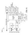
- FIG. 13illustrates another example of a wall outlet 1300 that is suitable for use as a wall outlet 130 , 150 , in the system of FIG. 1 .
- the wall outlet 1300is similar to the wall outlet 110 except, here, the horizontal run of the communication media 107 is a hybrid cable including both fiber optic and copper wire.
- each of the components of the wall outlet 1300functions as described with respect to the wall outlet 1100 , except in addition to or instead of sending signals over a CAT-5 or CAT-6 cable, the switch 1102 communicates with an active optical module 1304 to convert between electrical signals for the switch 1102 and optical signals on the fiber optic of the hybrid cable.
- the copper wire portion of the hybrid cablecan be used for power over Ethernet (PoE) to power the programmable processor 302 and the switch 1102 . Line power can also be used as an option for non-PoE installations.
- PoEpower over Ethernet
- the wall outlet 1300also includes a media access control/physical layer (MAC/PHY) device 1302 coupled between the programmable processor 302 and the switch 1102 .
- the MAC/PHY 1302can translate and forward information between the programmable processor 302 and the switch 1102 .
- the programmable processor 302can use this connection with the MAC/PHY 1302 and switch 1102 to communicate with the aggregation point 124 .
- the programmable processor 302can communicate PLI to the MAC/PHY 1302 which can provide the PLI to the switch 1102 which provides the PLI over the network 104 to the aggregation point 124 .
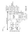
- FIG. 14illustrates another example of a wall outlet 1400 that is suitable for use as a wall outlet 130 , 150 , in the system of FIG. 1 .
- the wall outlet 1400is similar to the wall outlet 1300 except, wall outlet 1400 incorporates power over Ethernet (PoE) for one or more of the jacks 200 supported by the switch 1102 . Accordingly, each of the components of wall outlet 1400 functions as described with respect to wall outlet 1300 .
- the power supply unit 310is additionally coupled to one or more of the jacks 200 that are for coupling of communication media 107 to end user devices 106 .
- the power supply unit 310is configured to provide POE to the one or more jacks 200 in the wall outlet 1300 .
- This configurationmay use IEEE 802.3 at ⁇ 2009 PoE+ (25.5 W) link over the horizontal run of the communication media 107 to enable sufficient power supply of the PoE to the wall outlet 1400 .
- Line powercan also be used as an option for some or all of the PoE provided at the jacks 200 for coupling of communication media 107 to end user devices 106 that is coupled to switch 1102 .
- FIG. 15illustrates an example of the connection between a network device 1502 (e.g., switch 160 ) and a wall outlet 1300 , 1400 for either of the Examples 6 or 7 using a hybrid cable 107 described with respect to FIGS. 13 and 14 .
- a network switch 1504can be coupled to an active optical module 1506 for communicating optical signals to/from an active optical module 1304 of the wall outlet 1300 , 1400 over the optical fiber(s) of the hybrid cable 107 .
- a DC power source 1508can be coupled to a power interface 1510 to provide DC power (e.g., PoE) over the copper wires of the hybrid cable 107 to the power supply unit 310 of the wall outlet 1300 , 1400 .
- DC powere.g., PoE
- FIG. 16illustrates another example of a wall outlet 1600 that is suitable for use as a wall outlet device 130 , 150 in the system 100 of FIG. 1 .
- Wall outlet 1600can include one or more jacks 200 configured to mate with one or more connectors of one or more physical communication media 107 .
- the wall outlet 1600includes one jack 200 for mating with an optical cable and three jacks 200 for mating with a CAT-5 or CAT-6 cable, however other numbers and types of jacks can be used.
- the wall outlet 1600terminates a horizontal run of corresponding media 107 (e.g., multi-mode optical cable, CAT-5, CAT-6 cables) for each jack 200 .
- the wall outlet 1600is a passive wall outlet 150 such that each jack 200 terminates a horizontal run of a corresponding media 107 .
- the horizontal run of the corresponding media 107can be terminated at a switch (not shown) in the wall outlet 1600 .
- the wall outlet 1600terminates at least one run of a passive optical cable and at least one run of a twisted pair cable (e.g., CAT-5 or CAT-6 cable).
- the wall outlet 1600also includes an active module 1601 that comprises a programmable processor 302 that is coupled to a storage device.
- the programmable processor 302can include any suitable programmable processor, such as a microprocessor (e.g., an 8-bit microprocessor).
- the storage devicecan include, for example, an Electrically Erasable Programmable Read-Only Memory (EEPROM) or other non-volatile memory device.
- EEPROMElectrically Erasable Programmable Read-Only Memory
- the programmable processor 302 and the storage devicecan be the same die, on separate dies, or can be incorporated into a chip scale package.
- the programmable processor 302can be configured to communicate with a storage device or other component in a communication media 107 connected to a jack 200 over a media reading interface 108 of the respective jack 200 .
- the media reading interface 108while the corresponding connector is inserted into a front connector of a jack 200 , communicatively couples the programmable processor 302 to the corresponding PLM interface 216 so that the programmable processor 302 can access the storage device or other entity associated with the connector of the communication media 107 .
- the programmable processor 302is configured to obtain PLM information from communication media 107 connected (mated) with jacks 200 and send the PLM information to the aggregation point 124 .
- the programmable processor 302can also be configured to send PLI regarding itself to the aggregation point 124 as well as receiving information from the aggregation point 124 .
- the programmable processor 302can be configured to communicate with a wireless transceiver 1602 in the active module 1601 that is coupled to an antenna 1604 .
- the wireless transceiver 1602can translate and forward information between the programmable processor 302 and another entity (e.g., a wireless access point) through wireless communications.
- the wireless transceivercan use any suitable wireless transmission protocol including, but not limited to IEEE 802.11 (WiFi), IEEE 802.14.5 (ZigBee), and Bluetooth.
- the programmable processor 302can use this connection with the wireless transceiver 1602 to communicate with the aggregation point 124 .
- the wireless transceiver 1602can be wirelessly coupled to another device which is coupled to the network 104 .
- PLI and other informationcan be wirelessly transmitted to/from the other device.
- the devicecan provide the PLI over the network 104 to the aggregation point 124 .
- the programmable processor 302is not coupled to the aggregation point 124 in real time, and other device(s) can occasionally wirelessly couple with the wireless transceiver 1602 to obtain/provide PLI from/to the programmable processor 302 .
- the other device(s)can then also occasionally communicatively couple to the aggregation point 124 for synchronizing of PLI.
- the other devicecan be another wireless transceiver 1602 in a wall outlet 1600 .
- multiple wall outlets 1600can be wirelessly coupled together (e.g., in a mesh network) to provide a communication link from remote wall outlets 1600 to more centralized wall outlets 1600 having a wired connection to network 104 or a communication link to another wireless device (e.g., wireless access point) having a wired connection to network 104 .
- the centralized wall outletscan have a communicative coupling with the aggregation point 124 , thereby providing communicative coupling between the aggregation point 124 and the remote wall outlets 1600 .
- the centralized wall outlet(s)can include, in addition to including a wireless transceiver 1602 and antenna 1602 , a wired communicative coupling with the network 104 and/or aggregation point 124 as described in any of the Examples 1-7 in FIGS. 1-15 above.
- Such centralized wall outlet(s)can forward PLI between the aggregation point 124 and the remote wall outlet(s) 1600 .
- the remote wall outlets 1600can be communicatively coupled to the aggregation point 124 via wireless coupling with a centralized wall outlet(s).
- the wall outlet 1600enables the non-service traffic from all of its ports (jacks 200 ) to travel on paths (e.g., communication media 107 ) that are distinct from the paths of the service traffic (e.g., wireless signals).
- pathse.g., communication media 107
- the active module 1601includes a power supply unit 310 to obtain power from a line power source 1606 .
- the power supply unit 310can also optionally provide PoE to one or more of the jacks 200 .
- the power supply unit 310can include power harvesting circuits to harvest power from wireless signals sensed by the antenna 1604 .
- the power supply unit 310can provide power for the programmable processor 302 and the wireless transceiver 1602 .
- the active module 1601can also include a local input/output port 312 such as a UNIO port.
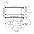
- FIG. 17illustrates another example of a wall outlet 1700 that is suitable for use as a wall outlet device 130 , 150 in the system 100 of FIG. 1 .
- Wall outlet 1700can include one or more jacks 200 configured to mate with one or more connectors of one or more physical communication media 107 .
- the wall outlet 1700includes one jack 200 for mating with an optical cable and three jacks 200 for mating with a CAT-5 or CAT-6 cable, however other numbers and types of jacks can be used.
- the wall outlet 1700terminates a horizontal run of corresponding media 107 (e.g., multi-mode optical cable, CAT-5, CAT-6 cables) for each jack 200 .
- the wall outlet 1700is a passive wall outlet 150 such that each jack 200 terminates a horizontal run of a corresponding media 107 .
- the horizontal run of the corresponding media 107can be terminated at a switch (not shown) in the wall outlet 1700 .
- the wall outlet 1700terminates at least one run of a passive optical cable and at least one run of a twisted pair cable (e.g., CAT-5 or CAT-6 cable).
- the wall outlet 1700also includes an active module 1701 that comprises a programmable processor 302 that is coupled to a storage device.
- the programmable processor 302can include any suitable programmable processor, such as a microprocessor (e.g., an 8-bit microprocessor).
- the storage devicecan include, for example, an Electrically Erasable Programmable Read-Only Memory (EEPROM) or other non-volatile memory device.
- EEPROMElectrically Erasable Programmable Read-Only Memory
- the programmable processor 302 and the storage devicecan be the same die, on separate dies, or can be incorporated into a chip scale package.
- the programmable processor 302can be configured to communicate with a storage device or other component in a communication media 107 connected to a jack 200 over a media reading interface 108 of the respective jack 200 .
- the media reading interface 108while the corresponding connector is inserted into a front connector of a jack 200 , communicatively couples the programmable processor 302 to the corresponding PLM interface 216 so that the programmable processor 302 can access the storage device or other entity associated with the connector of the communication media 107 .
- the programmable processor 302is configured to obtain PLM information from communication media 107 connected (mated) with jacks 200 and send the PLM information to the aggregation point 124 .
- the programmable processor 302can also be configured to send PLI regarding itself to another device as well as receiving information from another device.
- the programmable processor 302can be configured to communicate with a radio frequency identification (RFID) transceiver 1702 in the active module 1701 that is coupled to an antenna 1704 .
- the programmable processor 302can write information to the non-volatile memory (e.g., EEPROM) of the RFID transceiver 1704 .
- the RFID transceiver 1702can provide such PLI to the RFID reader.
- a device and/or user associated with the RFID readermay then provide such PLI to the aggregation point 124 for synchronizing of PLI.
- the RFID transceiver 1702can be either an active or a passive RFID transceiver.
- the wall outlet 1700enables the non-service traffic from all of its ports (jacks 200 ) to travel on paths (e.g., communication media 107 ) that are distinct from the paths of the service traffic (e.g., RFID signals).
- pathse.g., communication media 107
- the active module 1701also includes a power supply unit 310 to obtain power from a battery 1706 therein for powering of the programmable processor 302 .
- the battery 1706can be separate from any battery used to power (e.g., temporarily store) energy for the RFID transceiver 1702 .
- the battery 1706can also supply power to the RFID transceiver 1702 and be re-charged by the RFID transceiver 1702 .
- the power supply unit 310can include power harvesting circuits to harvest power from “non-RFID” wireless signals (as well as signals from an RFID reader interrogating the RFID transceiver 1702 ) sensed by the antenna 1704 to re-charge the battery 1706 .
- the active module 1701can also include a local input/output port 312 such as a UNIO port.
- wall outlet 300 , wall outlet 900 , wall outlet 1000 , wall outlet 1100 , wall outlet 1200 , wall outlet 1300 , wall outlet 1400 , wall outlet 1600 , and/or wall outlet 1700may be used within the same network.
- any of the Examples described above including a rear jack 200 for mating with a connector of a horizontal run of a communication media 107can include a media reading interface 108 in that rear jack 200 as described with respect to FIG. 2 .
- Such media reading interface 108can be coupled to the programmable processor 302 included in the wall outlet for obtaining and providing PLM information therefrom to the aggregation point 124 as described above.
Landscapes
- Engineering & Computer Science (AREA)
- Computer Networks & Wireless Communication (AREA)
- Signal Processing (AREA)
- Microelectronics & Electronic Packaging (AREA)
- Small-Scale Networks (AREA)
Abstract
Description
Claims (47)
Priority Applications (2)
| Application Number | Priority Date | Filing Date | Title |
|---|---|---|---|
| US13/937,314US9473361B2 (en) | 2012-07-11 | 2013-07-09 | Physical layer management at a wall plate device |
| US15/295,904US9742704B2 (en) | 2012-07-11 | 2016-10-17 | Physical layer management at a wall plate device |
Applications Claiming Priority (2)
| Application Number | Priority Date | Filing Date | Title |
|---|---|---|---|
| US201261670300P | 2012-07-11 | 2012-07-11 | |
| US13/937,314US9473361B2 (en) | 2012-07-11 | 2013-07-09 | Physical layer management at a wall plate device |
Related Child Applications (1)
| Application Number | Title | Priority Date | Filing Date |
|---|---|---|---|
| US15/295,904ContinuationUS9742704B2 (en) | 2012-07-11 | 2016-10-17 | Physical layer management at a wall plate device |
Publications (2)
| Publication Number | Publication Date |
|---|---|
| US20140016527A1 US20140016527A1 (en) | 2014-01-16 |
| US9473361B2true US9473361B2 (en) | 2016-10-18 |
Family
ID=49913928
Family Applications (2)
| Application Number | Title | Priority Date | Filing Date |
|---|---|---|---|
| US13/937,314Expired - Fee RelatedUS9473361B2 (en) | 2012-07-11 | 2013-07-09 | Physical layer management at a wall plate device |
| US15/295,904Expired - Fee RelatedUS9742704B2 (en) | 2012-07-11 | 2016-10-17 | Physical layer management at a wall plate device |
Family Applications After (1)
| Application Number | Title | Priority Date | Filing Date |
|---|---|---|---|
| US15/295,904Expired - Fee RelatedUS9742704B2 (en) | 2012-07-11 | 2016-10-17 | Physical layer management at a wall plate device |
Country Status (2)
| Country | Link |
|---|---|
| US (2) | US9473361B2 (en) |
| WO (1) | WO2014011714A1 (en) |
Cited By (2)
| Publication number | Priority date | Publication date | Assignee | Title |
|---|---|---|---|---|
| US9715776B2 (en) | 2012-06-25 | 2017-07-25 | Xceedid Corporation | Access credential reader connector |
| US20180210158A1 (en)* | 2015-07-30 | 2018-07-26 | Hewlett Packard Enterprise Development Lp | Transceiver modules |
Families Citing this family (14)
| Publication number | Priority date | Publication date | Assignee | Title |
|---|---|---|---|---|
| IN2014KN02956A (en)* | 2012-06-25 | 2015-05-08 | Adc Telecommunications Inc | |
| US9557505B2 (en) | 2013-03-18 | 2017-01-31 | Commscope Technologies Llc | Power and optical fiber interface |
| US11212177B2 (en)* | 2013-08-01 | 2021-12-28 | Commscope Connectivity Uk Limited | Hosted physical layer management or automated infrastructure management system having software only configuration and/or local hardware appliance |
| US12368615B2 (en) | 2013-09-19 | 2025-07-22 | Radius Universal Llc | Fiber optic communications and power network |
| US10277330B2 (en) | 2013-09-19 | 2019-04-30 | Radius Universal Llc | Fiber optic communications and power network |
| US10171180B2 (en)* | 2013-09-19 | 2019-01-01 | Radius Universal, LLC | Fiber optic communications and power network |
| EP3049838A4 (en) | 2013-09-24 | 2017-07-26 | CommScope Technologies LLC | Pluggable active optical module with managed connectivity support and simulated memory table |
| US9921557B2 (en) | 2014-01-15 | 2018-03-20 | SILVAIR Sp. z o.o. | Automation system comprising a monitoring device and methods therefor |
| WO2016073757A1 (en)* | 2014-11-05 | 2016-05-12 | Seed Labs Sp. Z O.O. | Sensory and control platform for an automation system |
| EP3291494B1 (en)* | 2016-08-31 | 2020-09-30 | Corning Optical Communications LLC | Distribution point unit to exchange communication data between a service provider and subscribers |
| CN111801555B (en) | 2017-10-16 | 2023-04-28 | 理查德·梅 | LAN cable conductor energy measurement, monitoring and management system |
| US10938167B2 (en) | 2018-03-06 | 2021-03-02 | Commscope Technologies Llc | Automated capture of information about fixed cabling |
| EP3763131A4 (en)* | 2018-03-08 | 2021-12-15 | Radius Universal, A Limited Liability Company of the State of New York | FIBER OPTICAL COMMUNICATION AND POWER NETWORK |
| WO2021050476A1 (en) | 2019-09-12 | 2021-03-18 | Commscope Technologies Llc | Internet of things (iot) system for cabling infrastructure |
Citations (196)
| Publication number | Priority date | Publication date | Assignee | Title |
|---|---|---|---|---|
| US5052940A (en) | 1990-05-11 | 1991-10-01 | Rit-Rad Interconnection Technologies Ltd. | Hermaphroditic self-shorting electrical connector |
| US5161988A (en) | 1991-02-13 | 1992-11-10 | Rit Technologies Ltd. | Patching panel |
| US5195902A (en) | 1990-05-11 | 1993-03-23 | Rit-Rad Interconnection Technologies Ltd. | Electrical connector |
| US5299944A (en) | 1992-11-16 | 1994-04-05 | Larabell Henri J | Universal bracket and assembly slide for storage devices |
| US5394503A (en) | 1993-10-08 | 1995-02-28 | Data Switch Corporation | Optical fiber connection monitoring apparatus, patch panel control system and method of using same |
| US5418334A (en) | 1993-08-04 | 1995-05-23 | Williams; Kenyon D. | Relative position tracer lamp indicator |
| US5420512A (en) | 1991-11-21 | 1995-05-30 | Paladin Corporation | Electronic cable testing system |
| US5448675A (en) | 1994-06-09 | 1995-09-05 | At&T Ipm Corp. | Telecommunications distribution frame with tracing |
| US5461693A (en) | 1994-07-14 | 1995-10-24 | At&T Ipm Corp. | Optical fiber distribution frame with fiber testing |
| US5463706A (en) | 1994-02-16 | 1995-10-31 | Thomas & Betts Corporation | Light traceable transmission conduit assembly |
| US5473715A (en) | 1994-05-03 | 1995-12-05 | Methode Electronics, Inc. | Hybrid fiber optic/electrical connector |
| US5483467A (en) | 1992-06-10 | 1996-01-09 | Rit Technologies, Ltd. | Patching panel scanner |
| US5487666A (en) | 1991-12-31 | 1996-01-30 | Digiovanni; Thomas H. | Schematic patch panel |
| US5541586A (en) | 1993-05-03 | 1996-07-30 | The Whitaker Corporation | Visual outlet identification in a cable management system |
| US5550755A (en) | 1994-07-14 | 1996-08-27 | Martin; B. Morgan | Apparatus and method for patch recording and recall |
| US5606664A (en) | 1990-05-21 | 1997-02-25 | Bay Networks, Inc. | Apparatus and method for automatically determining the topology of a local area network |
| US5649001A (en) | 1995-03-24 | 1997-07-15 | U.S. Robotics Mobile Communications Corp. | Method and apparatus for adapting a communication interface device to multiple networks |
| US5764043A (en) | 1996-12-20 | 1998-06-09 | Siecor Corporation | Traceable patch cord and connector assembly and method for locating patch cord ends |
| US5832071A (en) | 1995-11-24 | 1998-11-03 | Voelker Technologies, Inc. | Electronic patching system for telecommunications devices |
| US5854824A (en) | 1994-09-04 | 1998-12-29 | Rit Technologies Ltd. | Connectivity scanner |
| US5876240A (en) | 1997-04-01 | 1999-03-02 | The Whitaker Corp | Stacked electrical connector with visual indicators |
| US5909464A (en) | 1994-02-18 | 1999-06-01 | Telebit Corporation | Serial communications interface that supports multiple interface standards |
| US5910776A (en) | 1994-10-24 | 1999-06-08 | Id Technologies, Inc. | Method and apparatus for identifying locating or monitoring equipment or other objects |
| US5994998A (en) | 1997-05-29 | 1999-11-30 | 3Com Corporation | Power transfer apparatus for concurrently transmitting data and power over data wires |
| US6002331A (en) | 1998-07-20 | 1999-12-14 | Laor; Herzel | Method and apparatus for identifying and tracking connections of communication lines |
| US6212195B1 (en) | 1998-12-01 | 2001-04-03 | 3Com Corporation | Telecommunication apparatus and method for forwarding packets using separate collision domains |
| US6222908B1 (en) | 1999-09-23 | 2001-04-24 | Avaya Technology Corp. | Method and device for identifying a specific patch cord connector as it is introduced into, or removed from, a telecommunications patch system |
| US6223219B1 (en) | 1997-12-10 | 2001-04-24 | Nortel Networks Limited | Trail management across transport functionality of large and complex telecommunications networks |
| US20010001270A1 (en) | 1998-07-21 | 2001-05-17 | Adc Telecommunications, Inc. | Fiber optic module |
| US6234830B1 (en) | 1999-02-10 | 2001-05-22 | Avaya Technology Corp. | Tracing interface module for patch cords in a telecommunications system |
| US6238235B1 (en) | 1999-05-10 | 2001-05-29 | Rit Technologies Ltd. | Cable organizer |
| US6240090B1 (en) | 1997-12-19 | 2001-05-29 | Telefonaktiebolaget Lm Ericcson (Publ) | Self-configuring processors in an asynchronous transfer mode switch |
| US6285293B1 (en) | 1999-02-10 | 2001-09-04 | Avaya Technology Corp. | System and method for addressing and tracing patch cords in a dedicated telecommunications system |
| US6300877B1 (en) | 2000-03-10 | 2001-10-09 | Adc Telecommunications, Inc. | DSX baytracer illuminator |
| US6307880B1 (en) | 1997-10-24 | 2001-10-23 | 3Com Corporation | Method and system for externally incorporating automatic switching between voice and data communications |
| JP2001297044A (en) | 2000-04-13 | 2001-10-26 | Sharp Corp | Digital information equipment network device |
| US6330307B1 (en) | 1999-02-10 | 2001-12-11 | Avaya Technology Corp. | Display panel overlay structure and method for tracing interface modules in a telecommunications patch system |
| US6350148B1 (en) | 1999-02-10 | 2002-02-26 | Avaya Technology Corp. | Method and device for detecting the presence of a patch cord connector in a telecommunications patch system |
| US6359859B1 (en) | 1999-06-03 | 2002-03-19 | Fujitsu Network Communications, Inc. | Architecture for a hybrid STM/ATM add-drop multiplexer |
| US6368155B1 (en) | 1999-07-16 | 2002-04-09 | Molex Incorporated | Intelligent sensing connectors |
| US6424710B1 (en) | 1999-02-10 | 2002-07-23 | Avaya Technology Corp. | Method and device for detecting the presence of a patch cord connector in a telecommunications patch system using passive detection sensors |
| US6442032B1 (en) | 2001-08-10 | 2002-08-27 | Alcatel, Societe Anonyme | Ethernet switch module and system |
| US6449348B1 (en) | 1997-05-29 | 2002-09-10 | 3Com Corporation | Power transfer apparatus for use by network devices including telephone equipment |
| US20020138604A1 (en) | 1999-11-22 | 2002-09-26 | Beni Kopelovitz | Method and system for management of network domains |
| US6483203B1 (en) | 2000-06-08 | 2002-11-19 | 3Com Corporation | Single unit integrated transformer assembly |
| US6499861B1 (en) | 1999-09-23 | 2002-12-31 | Avaya Technology Corp. | Illuminated patch cord connector ports for use in a telecommunications patch closet having patch cord tracing capabilities |
| US6516345B1 (en) | 1999-04-30 | 2003-02-04 | Cisco Technology, Inc. | Approaches for determining actual physical topology of network based on gathered configuration information representing true neighboring devices |
| US6522737B1 (en) | 1999-02-10 | 2003-02-18 | Avaya Technology Corp. | System and method of operation for a telecommunications patch system |
| US20030046339A1 (en) | 2001-09-05 | 2003-03-06 | Ip Johnny Chong Ching | System and method for determining location and status of computer system server |
| US6535983B1 (en) | 1999-11-08 | 2003-03-18 | 3Com Corporation | System and method for signaling and detecting request for power over ethernet |
| US20030061393A1 (en) | 2001-09-21 | 2003-03-27 | Frank Steegmans | System and method for improving the management of information in networks by disposing machine accessible information tags along the interconnection means |
| US6564258B1 (en) | 1998-09-30 | 2003-05-13 | Nortel Networks Limited | Detection of network topology changes affecting trail routing consistency |
| US6574586B1 (en) | 1999-04-06 | 2003-06-03 | Itracs Corporation | System for monitoring connection pattern of data ports |
| US6574221B1 (en) | 1997-12-19 | 2003-06-03 | Telefonaktiebolaget Lm Ericsson (Publ) | Asynchronous transfer mode platform for mobile communications |
| US6577243B1 (en) | 1999-12-14 | 2003-06-10 | Alan J. Brown | Method and apparatus for tracing remote ends of networking cables |
| US20030194912A1 (en) | 2002-04-10 | 2003-10-16 | Powerdsine Ltd | Active area network connector |
| US20030197619A1 (en) | 2002-04-18 | 2003-10-23 | International Business Machines Corporation | Computer-server rack enclosure fault light diagnostic system |
| US20030219033A1 (en) | 2002-05-23 | 2003-11-27 | Silvester Kelan C. | Integrated medium access control device and physical layer device |
| US6684179B1 (en) | 1999-04-06 | 2004-01-27 | Itracs Corporation | System for monitoring connection pattern of data ports |
| US20040024717A1 (en) | 1998-04-03 | 2004-02-05 | Enerwise Global Technologies, Inc. | Computer assisted and/or implemented process and architecture for web-based monitoring of energy related usage, and client accessibility therefor |
| US20040073597A1 (en) | 2002-01-30 | 2004-04-15 | Caveney Jack E. | Systems and methods for managing a network |
| US6778505B1 (en) | 2000-01-03 | 2004-08-17 | Agere Systems Inc. | DSL automatic protocol detection system |
| US6880020B1 (en) | 2001-03-20 | 2005-04-12 | 3Com Corporation | Method and system for installing different communications jacks into an intelligent data concentrator |
| US6881096B2 (en) | 2002-04-15 | 2005-04-19 | Lantronix, Inc. | Compact serial-to-ethernet conversion port |
| US20050164548A1 (en) | 2004-01-22 | 2005-07-28 | Northstar Systems, Inc. | Computer input/output connector assembly |
| US20050177640A1 (en) | 2001-03-20 | 2005-08-11 | Alan Rubinstein | Method for selectively providing access to voice and data networks by use of intelligent hardware |
| US20050186819A1 (en) | 2004-01-20 | 2005-08-25 | Frank Velleca | Patch panel system |
| EP1569494A2 (en) | 2004-02-26 | 2005-08-31 | Fujitsu Limited | Optical network with selective mode switching |
| US20050190768A1 (en) | 2003-06-16 | 2005-09-01 | Ross Cutler | System and process for discovery of network-connected devices |
| USD510068S1 (en) | 2002-03-11 | 2005-09-27 | Rit Technologies Ltd | Patch panel for communication equipment |
| US6961675B2 (en) | 2000-03-14 | 2005-11-01 | Itracs Corporation | System for monitoring connection pattern of data ports |
| US6968994B1 (en) | 2004-07-06 | 2005-11-29 | Nortel Networks Ltd | RF-ID for cable management and port identification |
| US6976867B2 (en) | 2002-11-07 | 2005-12-20 | Tyco Electronics Amp Espana, S.A. | Network connection sensing assembly |
| US6993417B2 (en) | 2001-09-10 | 2006-01-31 | Osann Jr Robert | System for energy sensing analysis and feedback |
| US20060047800A1 (en) | 2004-08-24 | 2006-03-02 | Panduit Corporation | Systems and methods for network management |
| US20060059293A1 (en) | 2004-09-14 | 2006-03-16 | Henry Wurzburg | Universal serial bus switching hub |
| US7038135B1 (en) | 2004-06-28 | 2006-05-02 | Avaya Technology Corp. | Embedded cable connection identification circuits |
| US7039028B2 (en) | 2001-04-04 | 2006-05-02 | Telcordia Technologies, Inc. | Packet distribution and selection in soft handoff for IP-based base stations among multiple subnets |
| US7042562B2 (en) | 2002-12-26 | 2006-05-09 | Amphenol Corp. | Systems and methods for inspecting an optical interface |
| US7057105B2 (en) | 2004-02-24 | 2006-06-06 | Weidmüller Interface GmbH & Co. KG | Electrical distribution box |
| US7075910B2 (en) | 2001-04-04 | 2006-07-11 | Telcordia Technologies, Inc. | Distributed smooth handoff using shadow addresses in IP-based base stations |
| US7077710B2 (en) | 2001-03-21 | 2006-07-18 | Rit Technologies Ltd. | Patch panel |
| US20060160395A1 (en) | 2004-12-21 | 2006-07-20 | Commscope Solutions Properties, Llc | Methods, systems and computer program products for connecting and monitoring network equipment in a telecommunications system |
| US20060160396A1 (en) | 2004-12-21 | 2006-07-20 | Commscope Solutions Properties, Llc | Methods, systems and computer program products for notifying telecommunications system technicians of pending work orders |
| US7081808B2 (en) | 2002-09-13 | 2006-07-25 | Fitel Usa Corp. | Self-registration systems and methods for dynamically updating information related to a network |
| US20060179144A1 (en) | 2005-01-27 | 2006-08-10 | Nec Electronics Corporation | USB hub, USB-compliant apparatus, and communication system |
| US20060185887A1 (en) | 2005-02-22 | 2006-08-24 | Steven Neujahr | Wire support |
| US20060203715A1 (en) | 2005-03-14 | 2006-09-14 | International Business Machines Corporation | Method for redirection of virtual LAN network traffic |
| US20060227759A1 (en) | 2004-09-14 | 2006-10-12 | Bohm Mark R | Peripheral Sharing USB Hub |
| US7123810B2 (en) | 2004-05-04 | 2006-10-17 | Bellsouth Intellectual Property Corporation | Optical fiber connectors with identification circuits and distribution terminals that communicate therewith |
| US7126918B2 (en) | 2000-04-19 | 2006-10-24 | Caspian Networks, Inc. | Micro-flow management |
| US20060253561A1 (en) | 2003-02-04 | 2006-11-09 | Oyvind Holmeide | Method and apparatus for fast re-configuration of a network topology |
| US7136936B2 (en) | 2003-10-03 | 2006-11-14 | Asoka Usa Corporation | Method and system for virtual powerline local area networks |
| US7143299B1 (en) | 2001-03-20 | 2006-11-28 | 3Com Corporation | Method for power management of intelligent hardware |
| US7142536B1 (en) | 2000-12-14 | 2006-11-28 | Google, Inc. | Communications network quality of service system and method for real time information |
| US20060268747A1 (en) | 2005-05-11 | 2006-11-30 | Lucent Technologies Inc. | Method and apparatus for establishing spanning trees |
| US20060268507A1 (en) | 2005-05-26 | 2006-11-30 | Corrent Corporation | Computer input/output (I/O) connector assembly having a security circuit disposed therein |
| US20060282527A1 (en) | 2005-06-13 | 2006-12-14 | Accton Technology Corporation | System for very simple network management (VSNM) |
| US7153142B2 (en) | 2002-11-11 | 2006-12-26 | Rit Technologies Ltd. | Retrofit kit for interconnect cabling system |
| US7159026B2 (en) | 2002-01-31 | 2007-01-02 | Telcordia Technologies, Inc. | Service performance correlation and analysis |
| US20070025306A1 (en) | 2005-08-01 | 2007-02-01 | Cisco Technology, Inc. | Method and system for dynamic assignment of wireless LAN access point identity |
| US20070058338A1 (en) | 2005-08-27 | 2007-03-15 | Lee Hyun-Woo | Connector assembly and portable computer having the same |
| US20070117444A1 (en) | 2005-11-18 | 2007-05-24 | Panduit Corp. | Smart cable provisioning for a patch cord management system |
| US7226217B1 (en) | 2005-11-18 | 2007-06-05 | Stratos International, Inc. | Transceiver/fiber optic connector adaptor with patch cord ID reading capability |
| US7229020B2 (en) | 2002-09-25 | 2007-06-12 | Cormant Technologies, Inc. | Cabling system |
| US7234944B2 (en) | 2005-08-26 | 2007-06-26 | Panduit Corp. | Patch field documentation and revision systems |
| US20070153823A1 (en) | 2005-12-30 | 2007-07-05 | Jaroslaw Wojtowicz | Small form factor, pluggable ONU |
| US20070162954A1 (en) | 2003-04-07 | 2007-07-12 | Pela Peter L | Network security system based on physical location |
| US7254652B2 (en) | 2003-09-30 | 2007-08-07 | International Business Machines Corporation | Autonomic configuration of port speeds of components connected to an interconnection cable |
| US20070189321A1 (en) | 2006-02-15 | 2007-08-16 | Samsung Electronics Co., Ltd. | Method and apparatus for executing an application automatically according to the approach of wireless device |
| US7266087B2 (en) | 2001-11-30 | 2007-09-04 | Alcatel | IP platform for advanced multipoint access systems |
| US20070230452A1 (en) | 2006-03-22 | 2007-10-04 | Steve Hough | Intelligent patching system and method |
| US7289334B2 (en) | 2003-08-27 | 2007-10-30 | Epicenter, Inc. | Rack architecture and management system |
| US7299287B1 (en) | 2001-03-20 | 2007-11-20 | 3Com Corporation | Secure network outlet for supporting IP device address assigning functionality |
| US7297018B2 (en) | 2004-11-03 | 2007-11-20 | Panduit Corp. | Method and apparatus for patch panel patch cord documentation and revision |
| US20070274234A1 (en) | 2006-05-26 | 2007-11-29 | Fujitsu Limited | Network management method |
| US7312715B2 (en) | 2003-07-31 | 2007-12-25 | Rit Technologies Ltd. | Management of large scale cabling systems |
| US7315224B2 (en) | 2001-08-23 | 2008-01-01 | Rit Technologies Ltd. | High data rate interconnecting device |
| USD559186S1 (en) | 2004-09-20 | 2008-01-08 | Rit Technologies Ltd. | High-density patch panel |
| US7317735B1 (en) | 2002-06-27 | 2008-01-08 | Broadcom Corporation | Scrambler initialization in a wireless local area network |
| US7324488B1 (en) | 2003-02-10 | 2008-01-29 | 3Com Corporation | Method and system for providing an intelligent data concentrator communicatively coupled to a network by a wireless mode |
| US7328033B2 (en) | 2003-10-01 | 2008-02-05 | Rappaport Theodore S | Wireless network system and method |
| USD564966S1 (en) | 2004-06-02 | 2008-03-25 | Rit Technologies Ltd. | Telecommunication Connector |
| US7352289B1 (en) | 2003-09-11 | 2008-04-01 | Sun Microsystems, Inc. | System and method for detecting the connection state of a network cable connector |
| US7377819B1 (en) | 2006-04-27 | 2008-05-27 | Arrowhead Center, Inc. | Method and apparatus for improving network connection security with one or more cross-wired adapters |
| US7382765B2 (en) | 2003-04-30 | 2008-06-03 | Harris Corporation | Predictive routing in a moble ad hoc network |
| US20080159738A1 (en) | 2006-12-29 | 2008-07-03 | Lavranchuk James S | Identifiable fibers optics |
| US7401985B2 (en) | 2006-04-10 | 2008-07-22 | Finisar Corporation | Electrical-optical active optical cable |
| US20080181138A1 (en) | 2007-01-31 | 2008-07-31 | Hewlett-Packard Development Company, L.P. | Method of distributing multiple spanning tree protocol configuration |
| US20080181136A1 (en) | 2007-01-24 | 2008-07-31 | Fujitsu Limited | Medium having recorded therein network configuration verification program, network configuration verification method, and network configuration verification apparatus |
| US7411405B2 (en) | 2004-11-03 | 2008-08-12 | Panduit Corp. | Method and apparatus for reliable network cable connectivity |
| USD575743S1 (en) | 2005-09-21 | 2008-08-26 | Rit Technologies Ltd. | Block wiring tracing device |
| US20080219268A1 (en) | 2007-03-01 | 2008-09-11 | Dennison Larry R | Software control plane for switches and routers |
| US7433363B2 (en) | 2004-08-23 | 2008-10-07 | The United States Of America As Represented By The Secretary Of The Navy | Low latency switch architecture for high-performance packet-switched networks |
| US7440647B2 (en) | 2003-10-09 | 2008-10-21 | Finisar Corporation | Integrated optical assembly |
| US20080265915A1 (en) | 2007-04-24 | 2008-10-30 | Hewlett-Packard Development Company, L.P. | Method of detecting a network cabling change |
| US7445389B2 (en) | 2006-04-10 | 2008-11-04 | Finisar Corporation | Active optical cable with integrated eye safety |
| US7453864B2 (en) | 2003-04-30 | 2008-11-18 | Harris Corporation | Predictive route maintenance in a mobile ad hoc network |
| US7468669B1 (en) | 2005-06-21 | 2008-12-23 | Avaya Technology Corp. | RFID patch panels and cables |
| US7479032B2 (en) | 2006-10-10 | 2009-01-20 | Adc Gmbh | Upgradeable telecommunications patch panel and method of upgrading same |
| US7499616B2 (en) | 2006-04-10 | 2009-03-03 | Finisar Corporation | Active optical cable with electrical connector |
| US20090074404A1 (en) | 2000-08-15 | 2009-03-19 | Stephen Suryaputra | System, Device and Method for Managing Alternate Site Switching in an Optical Communication System |
| US7540667B2 (en) | 2007-08-01 | 2009-06-02 | Ortronics, Inc. | Positional differentiating connector assembly |
| US7564795B2 (en) | 2006-10-02 | 2009-07-21 | Cisco Technology, Inc. | Obtaining per-port location information for wired LAN switches |
| US20090195349A1 (en) | 2008-02-01 | 2009-08-06 | Energyhub | System and method for home energy monitor and control |
| US7586942B2 (en) | 2003-12-09 | 2009-09-08 | Dell Products L.P. | Identifying host computers at a physical layer |
| US7616589B2 (en) | 2003-02-19 | 2009-11-10 | Fujitsu Limited | Virtual LAN creation device |
| US20100020722A1 (en) | 2006-12-20 | 2010-01-28 | Farkas Janos | Method for Discovering the Physical Topology Of A Telecommunications Network |
| US20100040371A1 (en) | 2007-07-13 | 2010-02-18 | Huawei Technologies Co., Ltd. | Method, equipment, and system for detecting and authenticating terminal in passive optical network |
| US20100054157A1 (en) | 2007-01-19 | 2010-03-04 | Farkas Janos | Method And Apparatus For Network Tree Management |
| US7698156B2 (en) | 2002-01-29 | 2010-04-13 | Baxter International Inc. | System and method for identifying data streams associated with medical equipment |
| US7734038B2 (en) | 2006-05-01 | 2010-06-08 | Ortronics, Inc. | Electrical receptacle with open corner region |
| US7747272B2 (en) | 2006-05-01 | 2010-06-29 | Ortronics, Inc. | Wireless access point with temperature control system |
| US7744291B2 (en) | 2004-10-29 | 2010-06-29 | Finisar Corporation | Early self-validation of persistent memory during boot in an optical transceiver |
| US7765348B2 (en) | 2004-03-05 | 2010-07-27 | Finisar Corporation | Configurable two-wire interface module |
| US7778510B2 (en) | 2006-04-10 | 2010-08-17 | Finisar Corporation | Active optical cable electrical connector |
| US20100211664A1 (en)* | 2009-02-13 | 2010-08-19 | Adc Telecommunications, Inc. | Aggregation of physical layer information related to a network |
| US20100215362A1 (en) | 2007-05-29 | 2010-08-26 | Furukawa Electric Co., Ltd. | Customer premises optical network unit and optical transmission system |
| US7785138B2 (en) | 2004-01-12 | 2010-08-31 | Ortronics, Inc. | Wireless access point installation on an outlet box |
| US7785930B2 (en) | 2004-10-25 | 2010-08-31 | Finisar Corporation | Securing a transistor outline can within an optical component |
| US7787774B2 (en) | 2005-09-12 | 2010-08-31 | Finisar Corporation | Authentication modes for an optical transceiver module |
| US20100238003A1 (en) | 2009-03-17 | 2010-09-23 | Jetlun Corporation | Method and system for intelligent energy network management control system |
| US7809276B2 (en) | 2004-11-30 | 2010-10-05 | Finisar Corporation | Inter-transceiver module communication for optimization of link between transceivers |
| US7808399B2 (en) | 2005-12-20 | 2010-10-05 | Finisar Corporation | Electronic device enabling hardware and methods |
| US7809283B2 (en) | 2004-10-29 | 2010-10-05 | Finisar Corporation | Multi-transceiver module control with single microcontroller |
| US7819328B2 (en) | 2005-04-28 | 2010-10-26 | Finisar Corporation | Optical identification chips |
| US7839266B2 (en) | 2006-05-15 | 2010-11-23 | Linksense, Inc. | System and method for managing point of care assignments |
| US7841780B2 (en) | 2006-06-02 | 2010-11-30 | Finisar Corporation | Optical module for a host optical device |
| US7860399B2 (en) | 2005-01-25 | 2010-12-28 | Finisar Corporation | Host-independent link validation between optical communications modules |
| US7870242B2 (en) | 2008-10-01 | 2011-01-11 | Man Nguyen | Flexible compliance agent with integrated remediation |
| US7901144B2 (en) | 2008-03-14 | 2011-03-08 | Finisar Corporation | Optical interconnect solution |
| KR101020053B1 (en) | 2010-07-13 | 2011-03-09 | 주식회사 아론네트웍 | Automatic checking of optical cable connection in optical Ethernet transmission system with annular network structure |
| US7908406B2 (en) | 2006-06-21 | 2011-03-15 | Finisar Corporation | Interface architecture for facilitating communication regardless of protocol |
| KR20110027964A (en) | 2009-09-11 | 2011-03-17 | 주식회사 케이티네트웍스 | Communication device |
| US7920788B2 (en) | 2005-01-03 | 2011-04-05 | Finisar Corporation | Optical transceiver with clock for providing maintenance and lifetime information |
| US7933518B2 (en) | 2008-02-21 | 2011-04-26 | Finisar Corporation | Intelligent optical systems and methods for optical-layer management |
| US7957649B2 (en) | 2004-11-29 | 2011-06-07 | Finisar Corporation | Module command interface for an optical transceiver |
| US7957650B2 (en) | 2008-06-26 | 2011-06-07 | Finisar Corporation | Pluggable optical network unit capable of status indication |
| US7970283B2 (en) | 2005-03-07 | 2011-06-28 | Finisar Corporation | High speed SFP transceiver |
| US20110167269A1 (en) | 2010-01-06 | 2011-07-07 | Calix Networks, Inc. | Network device authentication |
| US7978800B2 (en) | 2002-10-10 | 2011-07-12 | Finisar Corporation | Circuit for converting a transponder controller chip output into an appropriate input signal for a host device |
| US8031992B2 (en) | 2004-05-07 | 2011-10-04 | Finisar Corporation | Optoelectronic module and method for producing an optoelectronic module |
| US8037173B2 (en) | 2008-05-30 | 2011-10-11 | Schneider Electric USA, Inc. | Message monitor, analyzer, recorder and viewer in a publisher-subscriber environment |
| US20110277001A1 (en) | 2010-05-06 | 2011-11-10 | Ikanos Communications, Inc. | Gateway Device |
| US8068739B2 (en) | 2003-06-12 | 2011-11-29 | Finisar Corporation | Modular optical device that interfaces with an external controller |
| US8083417B2 (en) | 2006-04-10 | 2011-12-27 | Finisar Corporation | Active optical cable electrical adaptor |
| US8107822B2 (en) | 2005-05-20 | 2012-01-31 | Finisar Corporation | Protocols for out-of-band communication |
| US8111999B2 (en) | 2004-10-29 | 2012-02-07 | Finisar Corporation | Inter-transceiver module communication for firmware upgrade |
| US8135282B2 (en) | 2008-07-31 | 2012-03-13 | Finisar Corporation | Fiberoptic transceiver module with integral status indicators |
| US8165297B2 (en) | 2003-11-21 | 2012-04-24 | Finisar Corporation | Transceiver with controller for authentication |
| US20120134366A1 (en) | 2009-06-26 | 2012-05-31 | Panduit Corp. | Physical layer management system |
| US8200097B2 (en) | 2008-09-05 | 2012-06-12 | Finisar Corporation | Optoelectronic module form-factor adapter |
| US8225024B2 (en) | 2004-03-05 | 2012-07-17 | Finisar Corporation | Use of a first two-wire interface communication to support the construction of a second two-wire interface communication |
| US8229301B2 (en) | 2004-09-07 | 2012-07-24 | Finisar Corporation | Configuration of optical transceivers to perform custom features |
| US8250246B2 (en) | 2008-07-09 | 2012-08-21 | Finisar Corporation | Loading and executing firmware module without resetting operation |
| US20130148976A1 (en) | 2011-12-07 | 2013-06-13 | Adc Telecommunications, Inc. | Systems and methods for using active optical cable segments |
Family Cites Families (1)
| Publication number | Priority date | Publication date | Assignee | Title |
|---|---|---|---|---|
| KR101330631B1 (en) | 2006-08-21 | 2013-11-18 | 삼성전자주식회사 | Method and apparatus for data transmitting using communication characteristic information |
- 2013
- 2013-07-09USUS13/937,314patent/US9473361B2/ennot_activeExpired - Fee Related
- 2013-07-10WOPCT/US2013/049832patent/WO2014011714A1/enactiveApplication Filing
- 2016
- 2016-10-17USUS15/295,904patent/US9742704B2/ennot_activeExpired - Fee Related
Patent Citations (212)
| Publication number | Priority date | Publication date | Assignee | Title |
|---|---|---|---|---|
| US5195902A (en) | 1990-05-11 | 1993-03-23 | Rit-Rad Interconnection Technologies Ltd. | Electrical connector |
| US5052940A (en) | 1990-05-11 | 1991-10-01 | Rit-Rad Interconnection Technologies Ltd. | Hermaphroditic self-shorting electrical connector |
| US5606664A (en) | 1990-05-21 | 1997-02-25 | Bay Networks, Inc. | Apparatus and method for automatically determining the topology of a local area network |
| US5161988A (en) | 1991-02-13 | 1992-11-10 | Rit Technologies Ltd. | Patching panel |
| US5420512A (en) | 1991-11-21 | 1995-05-30 | Paladin Corporation | Electronic cable testing system |
| US5487666A (en) | 1991-12-31 | 1996-01-30 | Digiovanni; Thomas H. | Schematic patch panel |
| US5483467A (en) | 1992-06-10 | 1996-01-09 | Rit Technologies, Ltd. | Patching panel scanner |
| US5299944A (en) | 1992-11-16 | 1994-04-05 | Larabell Henri J | Universal bracket and assembly slide for storage devices |
| US5541586A (en) | 1993-05-03 | 1996-07-30 | The Whitaker Corporation | Visual outlet identification in a cable management system |
| US5418334A (en) | 1993-08-04 | 1995-05-23 | Williams; Kenyon D. | Relative position tracer lamp indicator |
| US5394503A (en) | 1993-10-08 | 1995-02-28 | Data Switch Corporation | Optical fiber connection monitoring apparatus, patch panel control system and method of using same |
| US5463706A (en) | 1994-02-16 | 1995-10-31 | Thomas & Betts Corporation | Light traceable transmission conduit assembly |
| US5909464A (en) | 1994-02-18 | 1999-06-01 | Telebit Corporation | Serial communications interface that supports multiple interface standards |
| US5473715A (en) | 1994-05-03 | 1995-12-05 | Methode Electronics, Inc. | Hybrid fiber optic/electrical connector |
| US5448675A (en) | 1994-06-09 | 1995-09-05 | At&T Ipm Corp. | Telecommunications distribution frame with tracing |
| US5461693A (en) | 1994-07-14 | 1995-10-24 | At&T Ipm Corp. | Optical fiber distribution frame with fiber testing |
| US5550755A (en) | 1994-07-14 | 1996-08-27 | Martin; B. Morgan | Apparatus and method for patch recording and recall |
| US5854824A (en) | 1994-09-04 | 1998-12-29 | Rit Technologies Ltd. | Connectivity scanner |
| US5910776A (en) | 1994-10-24 | 1999-06-08 | Id Technologies, Inc. | Method and apparatus for identifying locating or monitoring equipment or other objects |
| US5649001A (en) | 1995-03-24 | 1997-07-15 | U.S. Robotics Mobile Communications Corp. | Method and apparatus for adapting a communication interface device to multiple networks |
| US5832071A (en) | 1995-11-24 | 1998-11-03 | Voelker Technologies, Inc. | Electronic patching system for telecommunications devices |
| US5764043A (en) | 1996-12-20 | 1998-06-09 | Siecor Corporation | Traceable patch cord and connector assembly and method for locating patch cord ends |
| US5876240A (en) | 1997-04-01 | 1999-03-02 | The Whitaker Corp | Stacked electrical connector with visual indicators |
| US6449348B1 (en) | 1997-05-29 | 2002-09-10 | 3Com Corporation | Power transfer apparatus for use by network devices including telephone equipment |
| US6496105B2 (en) | 1997-05-29 | 2002-12-17 | 3Com Corporation | Power transfer apparatus for concurrently transmitting data and power over data wires |
| US6140911A (en) | 1997-05-29 | 2000-10-31 | 3Com Corporation | Power transfer apparatus for concurrently transmitting data and power over data wires |
| US5994998A (en) | 1997-05-29 | 1999-11-30 | 3Com Corporation | Power transfer apparatus for concurrently transmitting data and power over data wires |
| US6329906B1 (en) | 1997-05-29 | 2001-12-11 | 3Com Corporation | Power transfer apparatus for concurrently transmitting data and power over data wires |
| US6307880B1 (en) | 1997-10-24 | 2001-10-23 | 3Com Corporation | Method and system for externally incorporating automatic switching between voice and data communications |
| US6223219B1 (en) | 1997-12-10 | 2001-04-24 | Nortel Networks Limited | Trail management across transport functionality of large and complex telecommunications networks |
| US6574221B1 (en) | 1997-12-19 | 2003-06-03 | Telefonaktiebolaget Lm Ericsson (Publ) | Asynchronous transfer mode platform for mobile communications |
| US6240090B1 (en) | 1997-12-19 | 2001-05-29 | Telefonaktiebolaget Lm Ericcson (Publ) | Self-configuring processors in an asynchronous transfer mode switch |
| US20040024717A1 (en) | 1998-04-03 | 2004-02-05 | Enerwise Global Technologies, Inc. | Computer assisted and/or implemented process and architecture for web-based monitoring of energy related usage, and client accessibility therefor |
| US6002331A (en) | 1998-07-20 | 1999-12-14 | Laor; Herzel | Method and apparatus for identifying and tracking connections of communication lines |
| US20010001270A1 (en) | 1998-07-21 | 2001-05-17 | Adc Telecommunications, Inc. | Fiber optic module |
| US6564258B1 (en) | 1998-09-30 | 2003-05-13 | Nortel Networks Limited | Detection of network topology changes affecting trail routing consistency |
| US6212195B1 (en) | 1998-12-01 | 2001-04-03 | 3Com Corporation | Telecommunication apparatus and method for forwarding packets using separate collision domains |
| US6330307B1 (en) | 1999-02-10 | 2001-12-11 | Avaya Technology Corp. | Display panel overlay structure and method for tracing interface modules in a telecommunications patch system |
| US6350148B1 (en) | 1999-02-10 | 2002-02-26 | Avaya Technology Corp. | Method and device for detecting the presence of a patch cord connector in a telecommunications patch system |
| US6234830B1 (en) | 1999-02-10 | 2001-05-22 | Avaya Technology Corp. | Tracing interface module for patch cords in a telecommunications system |
| US6424710B1 (en) | 1999-02-10 | 2002-07-23 | Avaya Technology Corp. | Method and device for detecting the presence of a patch cord connector in a telecommunications patch system using passive detection sensors |
| US6285293B1 (en) | 1999-02-10 | 2001-09-04 | Avaya Technology Corp. | System and method for addressing and tracing patch cords in a dedicated telecommunications system |
| US6522737B1 (en) | 1999-02-10 | 2003-02-18 | Avaya Technology Corp. | System and method of operation for a telecommunications patch system |
| US6684179B1 (en) | 1999-04-06 | 2004-01-27 | Itracs Corporation | System for monitoring connection pattern of data ports |
| US7160143B2 (en) | 1999-04-06 | 2007-01-09 | Itracs Corporation | System for monitoring connection pattern of data ports |
| US6725177B2 (en) | 1999-04-06 | 2004-04-20 | Itracs Corporation | System for monitoring connection pattern of data ports |
| US6574586B1 (en) | 1999-04-06 | 2003-06-03 | Itracs Corporation | System for monitoring connection pattern of data ports |
| US6516345B1 (en) | 1999-04-30 | 2003-02-04 | Cisco Technology, Inc. | Approaches for determining actual physical topology of network based on gathered configuration information representing true neighboring devices |
| US6238235B1 (en) | 1999-05-10 | 2001-05-29 | Rit Technologies Ltd. | Cable organizer |
| US6359859B1 (en) | 1999-06-03 | 2002-03-19 | Fujitsu Network Communications, Inc. | Architecture for a hybrid STM/ATM add-drop multiplexer |
| US6368155B1 (en) | 1999-07-16 | 2002-04-09 | Molex Incorporated | Intelligent sensing connectors |
| US6222908B1 (en) | 1999-09-23 | 2001-04-24 | Avaya Technology Corp. | Method and device for identifying a specific patch cord connector as it is introduced into, or removed from, a telecommunications patch system |
| US6499861B1 (en) | 1999-09-23 | 2002-12-31 | Avaya Technology Corp. | Illuminated patch cord connector ports for use in a telecommunications patch closet having patch cord tracing capabilities |
| US6535983B1 (en) | 1999-11-08 | 2003-03-18 | 3Com Corporation | System and method for signaling and detecting request for power over ethernet |
| US20020138604A1 (en) | 1999-11-22 | 2002-09-26 | Beni Kopelovitz | Method and system for management of network domains |
| US6577243B1 (en) | 1999-12-14 | 2003-06-10 | Alan J. Brown | Method and apparatus for tracing remote ends of networking cables |
| US7483419B2 (en) | 2000-01-03 | 2009-01-27 | Agere Systems Inc. | DSL automatic protocol detection system |
| US6778505B1 (en) | 2000-01-03 | 2004-08-17 | Agere Systems Inc. | DSL automatic protocol detection system |
| US6636152B2 (en) | 2000-03-10 | 2003-10-21 | Adc Telecommunications, Inc. | DSX illuminator |
| US6300877B1 (en) | 2000-03-10 | 2001-10-09 | Adc Telecommunications, Inc. | DSX baytracer illuminator |
| US6961675B2 (en) | 2000-03-14 | 2005-11-01 | Itracs Corporation | System for monitoring connection pattern of data ports |
| JP2001297044A (en) | 2000-04-13 | 2001-10-26 | Sharp Corp | Digital information equipment network device |
| US7126918B2 (en) | 2000-04-19 | 2006-10-24 | Caspian Networks, Inc. | Micro-flow management |
| US6483203B1 (en) | 2000-06-08 | 2002-11-19 | 3Com Corporation | Single unit integrated transformer assembly |
| US20090074404A1 (en) | 2000-08-15 | 2009-03-19 | Stephen Suryaputra | System, Device and Method for Managing Alternate Site Switching in an Optical Communication System |
| US7142536B1 (en) | 2000-12-14 | 2006-11-28 | Google, Inc. | Communications network quality of service system and method for real time information |
| US20050177640A1 (en) | 2001-03-20 | 2005-08-11 | Alan Rubinstein | Method for selectively providing access to voice and data networks by use of intelligent hardware |
| US6880020B1 (en) | 2001-03-20 | 2005-04-12 | 3Com Corporation | Method and system for installing different communications jacks into an intelligent data concentrator |
| US7299287B1 (en) | 2001-03-20 | 2007-11-20 | 3Com Corporation | Secure network outlet for supporting IP device address assigning functionality |
| US7143299B1 (en) | 2001-03-20 | 2006-11-28 | 3Com Corporation | Method for power management of intelligent hardware |
| US7077710B2 (en) | 2001-03-21 | 2006-07-18 | Rit Technologies Ltd. | Patch panel |
| US7075910B2 (en) | 2001-04-04 | 2006-07-11 | Telcordia Technologies, Inc. | Distributed smooth handoff using shadow addresses in IP-based base stations |
| US7039028B2 (en) | 2001-04-04 | 2006-05-02 | Telcordia Technologies, Inc. | Packet distribution and selection in soft handoff for IP-based base stations among multiple subnets |
| US6442032B1 (en) | 2001-08-10 | 2002-08-27 | Alcatel, Societe Anonyme | Ethernet switch module and system |
| US7315224B2 (en) | 2001-08-23 | 2008-01-01 | Rit Technologies Ltd. | High data rate interconnecting device |
| US20030046339A1 (en) | 2001-09-05 | 2003-03-06 | Ip Johnny Chong Ching | System and method for determining location and status of computer system server |
| US6993417B2 (en) | 2001-09-10 | 2006-01-31 | Osann Jr Robert | System for energy sensing analysis and feedback |
| US20030061393A1 (en) | 2001-09-21 | 2003-03-27 | Frank Steegmans | System and method for improving the management of information in networks by disposing machine accessible information tags along the interconnection means |
| US7266087B2 (en) | 2001-11-30 | 2007-09-04 | Alcatel | IP platform for advanced multipoint access systems |
| US7698156B2 (en) | 2002-01-29 | 2010-04-13 | Baxter International Inc. | System and method for identifying data streams associated with medical equipment |
| US20040073597A1 (en) | 2002-01-30 | 2004-04-15 | Caveney Jack E. | Systems and methods for managing a network |
| US7159026B2 (en) | 2002-01-31 | 2007-01-02 | Telcordia Technologies, Inc. | Service performance correlation and analysis |
| USD510068S1 (en) | 2002-03-11 | 2005-09-27 | Rit Technologies Ltd | Patch panel for communication equipment |
| US20030194912A1 (en) | 2002-04-10 | 2003-10-16 | Powerdsine Ltd | Active area network connector |
| US6881096B2 (en) | 2002-04-15 | 2005-04-19 | Lantronix, Inc. | Compact serial-to-ethernet conversion port |
| US20030197619A1 (en) | 2002-04-18 | 2003-10-23 | International Business Machines Corporation | Computer-server rack enclosure fault light diagnostic system |
| US20030219033A1 (en) | 2002-05-23 | 2003-11-27 | Silvester Kelan C. | Integrated medium access control device and physical layer device |
| US7317735B1 (en) | 2002-06-27 | 2008-01-08 | Broadcom Corporation | Scrambler initialization in a wireless local area network |
| US7081808B2 (en) | 2002-09-13 | 2006-07-25 | Fitel Usa Corp. | Self-registration systems and methods for dynamically updating information related to a network |
| US7229020B2 (en) | 2002-09-25 | 2007-06-12 | Cormant Technologies, Inc. | Cabling system |
| US7978800B2 (en) | 2002-10-10 | 2011-07-12 | Finisar Corporation | Circuit for converting a transponder controller chip output into an appropriate input signal for a host device |
| US6976867B2 (en) | 2002-11-07 | 2005-12-20 | Tyco Electronics Amp Espana, S.A. | Network connection sensing assembly |
| US7153142B2 (en) | 2002-11-11 | 2006-12-26 | Rit Technologies Ltd. | Retrofit kit for interconnect cabling system |
| US7042562B2 (en) | 2002-12-26 | 2006-05-09 | Amphenol Corp. | Systems and methods for inspecting an optical interface |
| US20060253561A1 (en) | 2003-02-04 | 2006-11-09 | Oyvind Holmeide | Method and apparatus for fast re-configuration of a network topology |
| US7324488B1 (en) | 2003-02-10 | 2008-01-29 | 3Com Corporation | Method and system for providing an intelligent data concentrator communicatively coupled to a network by a wireless mode |
| US7616589B2 (en) | 2003-02-19 | 2009-11-10 | Fujitsu Limited | Virtual LAN creation device |
| US20070162954A1 (en) | 2003-04-07 | 2007-07-12 | Pela Peter L | Network security system based on physical location |
| US7382765B2 (en) | 2003-04-30 | 2008-06-03 | Harris Corporation | Predictive routing in a moble ad hoc network |
| US7453864B2 (en) | 2003-04-30 | 2008-11-18 | Harris Corporation | Predictive route maintenance in a mobile ad hoc network |
| WO2004105317A1 (en) | 2003-05-16 | 2004-12-02 | Panduit Corp. | Systems and methods for managing a network using active jacks |
| US8068739B2 (en) | 2003-06-12 | 2011-11-29 | Finisar Corporation | Modular optical device that interfaces with an external controller |
| US20050190768A1 (en) | 2003-06-16 | 2005-09-01 | Ross Cutler | System and process for discovery of network-connected devices |
| US7312715B2 (en) | 2003-07-31 | 2007-12-25 | Rit Technologies Ltd. | Management of large scale cabling systems |
| US7289334B2 (en) | 2003-08-27 | 2007-10-30 | Epicenter, Inc. | Rack architecture and management system |
| US7551456B2 (en) | 2003-08-27 | 2009-06-23 | Epicenter, Inc. | Rack architecture and management system |
| US7352289B1 (en) | 2003-09-11 | 2008-04-01 | Sun Microsystems, Inc. | System and method for detecting the connection state of a network cable connector |
| US7254652B2 (en) | 2003-09-30 | 2007-08-07 | International Business Machines Corporation | Autonomic configuration of port speeds of components connected to an interconnection cable |
| US7328033B2 (en) | 2003-10-01 | 2008-02-05 | Rappaport Theodore S | Wireless network system and method |
| US7136936B2 (en) | 2003-10-03 | 2006-11-14 | Asoka Usa Corporation | Method and system for virtual powerline local area networks |
| US7440647B2 (en) | 2003-10-09 | 2008-10-21 | Finisar Corporation | Integrated optical assembly |
| US8165297B2 (en) | 2003-11-21 | 2012-04-24 | Finisar Corporation | Transceiver with controller for authentication |
| US7586942B2 (en) | 2003-12-09 | 2009-09-08 | Dell Products L.P. | Identifying host computers at a physical layer |
| US7785138B2 (en) | 2004-01-12 | 2010-08-31 | Ortronics, Inc. | Wireless access point installation on an outlet box |
| US7193422B2 (en) | 2004-01-20 | 2007-03-20 | The Siemon Company | Patch panel system |
| US20050186819A1 (en) | 2004-01-20 | 2005-08-25 | Frank Velleca | Patch panel system |
| US20050164548A1 (en) | 2004-01-22 | 2005-07-28 | Northstar Systems, Inc. | Computer input/output connector assembly |
| US7057105B2 (en) | 2004-02-24 | 2006-06-06 | Weidmüller Interface GmbH & Co. KG | Electrical distribution box |
| EP1569494A2 (en) | 2004-02-26 | 2005-08-31 | Fujitsu Limited | Optical network with selective mode switching |
| US8225024B2 (en) | 2004-03-05 | 2012-07-17 | Finisar Corporation | Use of a first two-wire interface communication to support the construction of a second two-wire interface communication |
| US7765348B2 (en) | 2004-03-05 | 2010-07-27 | Finisar Corporation | Configurable two-wire interface module |
| US7123810B2 (en) | 2004-05-04 | 2006-10-17 | Bellsouth Intellectual Property Corporation | Optical fiber connectors with identification circuits and distribution terminals that communicate therewith |
| US8031992B2 (en) | 2004-05-07 | 2011-10-04 | Finisar Corporation | Optoelectronic module and method for producing an optoelectronic module |
| USD564966S1 (en) | 2004-06-02 | 2008-03-25 | Rit Technologies Ltd. | Telecommunication Connector |
| US7038135B1 (en) | 2004-06-28 | 2006-05-02 | Avaya Technology Corp. | Embedded cable connection identification circuits |
| US6968994B1 (en) | 2004-07-06 | 2005-11-29 | Nortel Networks Ltd | RF-ID for cable management and port identification |
| US7433363B2 (en) | 2004-08-23 | 2008-10-07 | The United States Of America As Represented By The Secretary Of The Navy | Low latency switch architecture for high-performance packet-switched networks |
| US20060047800A1 (en) | 2004-08-24 | 2006-03-02 | Panduit Corporation | Systems and methods for network management |
| US8229301B2 (en) | 2004-09-07 | 2012-07-24 | Finisar Corporation | Configuration of optical transceivers to perform custom features |
| US20060227759A1 (en) | 2004-09-14 | 2006-10-12 | Bohm Mark R | Peripheral Sharing USB Hub |
| US20060059293A1 (en) | 2004-09-14 | 2006-03-16 | Henry Wurzburg | Universal serial bus switching hub |
| USD559186S1 (en) | 2004-09-20 | 2008-01-08 | Rit Technologies Ltd. | High-density patch panel |
| US7785930B2 (en) | 2004-10-25 | 2010-08-31 | Finisar Corporation | Securing a transistor outline can within an optical component |
| US8267600B2 (en) | 2004-10-29 | 2012-09-18 | Finisar Corporation | Early self-validation of persistent memory during boot in an optical transceiver |
| US8111999B2 (en) | 2004-10-29 | 2012-02-07 | Finisar Corporation | Inter-transceiver module communication for firmware upgrade |
| US7744291B2 (en) | 2004-10-29 | 2010-06-29 | Finisar Corporation | Early self-validation of persistent memory during boot in an optical transceiver |
| US7809283B2 (en) | 2004-10-29 | 2010-10-05 | Finisar Corporation | Multi-transceiver module control with single microcontroller |
| US7297018B2 (en) | 2004-11-03 | 2007-11-20 | Panduit Corp. | Method and apparatus for patch panel patch cord documentation and revision |
| US7411405B2 (en) | 2004-11-03 | 2008-08-12 | Panduit Corp. | Method and apparatus for reliable network cable connectivity |
| US7517243B2 (en) | 2004-11-03 | 2009-04-14 | Panduit Corp. | Method and apparatus for patch panel patch cord documentation and revision |
| US7957649B2 (en) | 2004-11-29 | 2011-06-07 | Finisar Corporation | Module command interface for an optical transceiver |
| US7809276B2 (en) | 2004-11-30 | 2010-10-05 | Finisar Corporation | Inter-transceiver module communication for optimization of link between transceivers |
| US20060160396A1 (en) | 2004-12-21 | 2006-07-20 | Commscope Solutions Properties, Llc | Methods, systems and computer program products for notifying telecommunications system technicians of pending work orders |
| US20060160395A1 (en) | 2004-12-21 | 2006-07-20 | Commscope Solutions Properties, Llc | Methods, systems and computer program products for connecting and monitoring network equipment in a telecommunications system |
| US8233793B2 (en) | 2005-01-03 | 2012-07-31 | Finisar Corporation | Optical transceiver with clock for providing maintenance and lifetime information |
| US7920788B2 (en) | 2005-01-03 | 2011-04-05 | Finisar Corporation | Optical transceiver with clock for providing maintenance and lifetime information |
| US7860399B2 (en) | 2005-01-25 | 2010-12-28 | Finisar Corporation | Host-independent link validation between optical communications modules |
| US20060179144A1 (en) | 2005-01-27 | 2006-08-10 | Nec Electronics Corporation | USB hub, USB-compliant apparatus, and communication system |
| US20060185887A1 (en) | 2005-02-22 | 2006-08-24 | Steven Neujahr | Wire support |
| US7970283B2 (en) | 2005-03-07 | 2011-06-28 | Finisar Corporation | High speed SFP transceiver |
| US20060203715A1 (en) | 2005-03-14 | 2006-09-14 | International Business Machines Corporation | Method for redirection of virtual LAN network traffic |
| US7819328B2 (en) | 2005-04-28 | 2010-10-26 | Finisar Corporation | Optical identification chips |
| US20060268747A1 (en) | 2005-05-11 | 2006-11-30 | Lucent Technologies Inc. | Method and apparatus for establishing spanning trees |
| US8107822B2 (en) | 2005-05-20 | 2012-01-31 | Finisar Corporation | Protocols for out-of-band communication |
| US20060268507A1 (en) | 2005-05-26 | 2006-11-30 | Corrent Corporation | Computer input/output (I/O) connector assembly having a security circuit disposed therein |
| US20060282527A1 (en) | 2005-06-13 | 2006-12-14 | Accton Technology Corporation | System for very simple network management (VSNM) |
| US7468669B1 (en) | 2005-06-21 | 2008-12-23 | Avaya Technology Corp. | RFID patch panels and cables |
| US20070025306A1 (en) | 2005-08-01 | 2007-02-01 | Cisco Technology, Inc. | Method and system for dynamic assignment of wireless LAN access point identity |
| US7234944B2 (en) | 2005-08-26 | 2007-06-26 | Panduit Corp. | Patch field documentation and revision systems |
| US20070058338A1 (en) | 2005-08-27 | 2007-03-15 | Lee Hyun-Woo | Connector assembly and portable computer having the same |
| US8155528B2 (en) | 2005-09-12 | 2012-04-10 | Finisar Corporation | Authentication modes for an optical transceiver module |
| US7787774B2 (en) | 2005-09-12 | 2010-08-31 | Finisar Corporation | Authentication modes for an optical transceiver module |
| USD575743S1 (en) | 2005-09-21 | 2008-08-26 | Rit Technologies Ltd. | Block wiring tracing device |
| US7226217B1 (en) | 2005-11-18 | 2007-06-05 | Stratos International, Inc. | Transceiver/fiber optic connector adaptor with patch cord ID reading capability |
| US20070117444A1 (en) | 2005-11-18 | 2007-05-24 | Panduit Corp. | Smart cable provisioning for a patch cord management system |
| US7808399B2 (en) | 2005-12-20 | 2010-10-05 | Finisar Corporation | Electronic device enabling hardware and methods |
| US20070153823A1 (en) | 2005-12-30 | 2007-07-05 | Jaroslaw Wojtowicz | Small form factor, pluggable ONU |
| US20070189321A1 (en) | 2006-02-15 | 2007-08-16 | Samsung Electronics Co., Ltd. | Method and apparatus for executing an application automatically according to the approach of wireless device |
| US20070230452A1 (en) | 2006-03-22 | 2007-10-04 | Steve Hough | Intelligent patching system and method |
| US7445389B2 (en) | 2006-04-10 | 2008-11-04 | Finisar Corporation | Active optical cable with integrated eye safety |
| US7778510B2 (en) | 2006-04-10 | 2010-08-17 | Finisar Corporation | Active optical cable electrical connector |
| US7499616B2 (en) | 2006-04-10 | 2009-03-03 | Finisar Corporation | Active optical cable with electrical connector |
| US7762727B2 (en) | 2006-04-10 | 2010-07-27 | Finisar Corporation | Active optical cable with integrated control features |
| US7401985B2 (en) | 2006-04-10 | 2008-07-22 | Finisar Corporation | Electrical-optical active optical cable |
| US8083417B2 (en) | 2006-04-10 | 2011-12-27 | Finisar Corporation | Active optical cable electrical adaptor |
| US7377819B1 (en) | 2006-04-27 | 2008-05-27 | Arrowhead Center, Inc. | Method and apparatus for improving network connection security with one or more cross-wired adapters |
| US7747272B2 (en) | 2006-05-01 | 2010-06-29 | Ortronics, Inc. | Wireless access point with temperature control system |
| US7734038B2 (en) | 2006-05-01 | 2010-06-08 | Ortronics, Inc. | Electrical receptacle with open corner region |
| US7839266B2 (en) | 2006-05-15 | 2010-11-23 | Linksense, Inc. | System and method for managing point of care assignments |
| US20070274234A1 (en) | 2006-05-26 | 2007-11-29 | Fujitsu Limited | Network management method |
| US7841780B2 (en) | 2006-06-02 | 2010-11-30 | Finisar Corporation | Optical module for a host optical device |
| US7908406B2 (en) | 2006-06-21 | 2011-03-15 | Finisar Corporation | Interface architecture for facilitating communication regardless of protocol |
| US7564795B2 (en) | 2006-10-02 | 2009-07-21 | Cisco Technology, Inc. | Obtaining per-port location information for wired LAN switches |
| US7479032B2 (en) | 2006-10-10 | 2009-01-20 | Adc Gmbh | Upgradeable telecommunications patch panel and method of upgrading same |
| US20100020722A1 (en) | 2006-12-20 | 2010-01-28 | Farkas Janos | Method for Discovering the Physical Topology Of A Telecommunications Network |
| US20080159738A1 (en) | 2006-12-29 | 2008-07-03 | Lavranchuk James S | Identifiable fibers optics |
| US20100054157A1 (en) | 2007-01-19 | 2010-03-04 | Farkas Janos | Method And Apparatus For Network Tree Management |
| US20080181136A1 (en) | 2007-01-24 | 2008-07-31 | Fujitsu Limited | Medium having recorded therein network configuration verification program, network configuration verification method, and network configuration verification apparatus |
| US20080181138A1 (en) | 2007-01-31 | 2008-07-31 | Hewlett-Packard Development Company, L.P. | Method of distributing multiple spanning tree protocol configuration |
| US20080219268A1 (en) | 2007-03-01 | 2008-09-11 | Dennison Larry R | Software control plane for switches and routers |
| US20080265915A1 (en) | 2007-04-24 | 2008-10-30 | Hewlett-Packard Development Company, L.P. | Method of detecting a network cabling change |
| US20100215362A1 (en) | 2007-05-29 | 2010-08-26 | Furukawa Electric Co., Ltd. | Customer premises optical network unit and optical transmission system |
| US20100040371A1 (en) | 2007-07-13 | 2010-02-18 | Huawei Technologies Co., Ltd. | Method, equipment, and system for detecting and authenticating terminal in passive optical network |
| US7540667B2 (en) | 2007-08-01 | 2009-06-02 | Ortronics, Inc. | Positional differentiating connector assembly |
| US20090195349A1 (en) | 2008-02-01 | 2009-08-06 | Energyhub | System and method for home energy monitor and control |
| US7933518B2 (en) | 2008-02-21 | 2011-04-26 | Finisar Corporation | Intelligent optical systems and methods for optical-layer management |
| US7901144B2 (en) | 2008-03-14 | 2011-03-08 | Finisar Corporation | Optical interconnect solution |
| US8037173B2 (en) | 2008-05-30 | 2011-10-11 | Schneider Electric USA, Inc. | Message monitor, analyzer, recorder and viewer in a publisher-subscriber environment |
| US7957650B2 (en) | 2008-06-26 | 2011-06-07 | Finisar Corporation | Pluggable optical network unit capable of status indication |
| US8250246B2 (en) | 2008-07-09 | 2012-08-21 | Finisar Corporation | Loading and executing firmware module without resetting operation |
| US8135282B2 (en) | 2008-07-31 | 2012-03-13 | Finisar Corporation | Fiberoptic transceiver module with integral status indicators |
| US8200097B2 (en) | 2008-09-05 | 2012-06-12 | Finisar Corporation | Optoelectronic module form-factor adapter |
| US7870242B2 (en) | 2008-10-01 | 2011-01-11 | Man Nguyen | Flexible compliance agent with integrated remediation |
| US20100211664A1 (en)* | 2009-02-13 | 2010-08-19 | Adc Telecommunications, Inc. | Aggregation of physical layer information related to a network |
| US20100215049A1 (en)* | 2009-02-13 | 2010-08-26 | Adc Telecommunications, Inc. | Inter-networking devices for use with physical layer information |
| US20100238003A1 (en) | 2009-03-17 | 2010-09-23 | Jetlun Corporation | Method and system for intelligent energy network management control system |
| US20120134366A1 (en) | 2009-06-26 | 2012-05-31 | Panduit Corp. | Physical layer management system |
| KR20110027964A (en) | 2009-09-11 | 2011-03-17 | 주식회사 케이티네트웍스 | Communication device |
| US20110167269A1 (en) | 2010-01-06 | 2011-07-07 | Calix Networks, Inc. | Network device authentication |
| US20110277001A1 (en) | 2010-05-06 | 2011-11-10 | Ikanos Communications, Inc. | Gateway Device |
| KR101020053B1 (en) | 2010-07-13 | 2011-03-09 | 주식회사 아론네트웍 | Automatic checking of optical cable connection in optical Ethernet transmission system with annular network structure |
| US20130148976A1 (en) | 2011-12-07 | 2013-06-13 | Adc Telecommunications, Inc. | Systems and methods for using active optical cable segments |
Non-Patent Citations (29)
Cited By (5)
| Publication number | Priority date | Publication date | Assignee | Title |
|---|---|---|---|---|
| US9715776B2 (en) | 2012-06-25 | 2017-07-25 | Xceedid Corporation | Access credential reader connector |
| US10176653B2 (en) | 2012-06-25 | 2019-01-08 | Schlage Lock Company Llc | Access credential reader connector |
| US10553051B2 (en) | 2012-06-25 | 2020-02-04 | Schlage Lock Company Llc | Access credential reader connector |
| US20180210158A1 (en)* | 2015-07-30 | 2018-07-26 | Hewlett Packard Enterprise Development Lp | Transceiver modules |
| US10502910B2 (en)* | 2015-07-30 | 2019-12-10 | Hewlett Packard Enterprise Development Lp | Transceiver modules |
Also Published As
| Publication number | Publication date |
|---|---|
| US20170034079A1 (en) | 2017-02-02 |
| US20140016527A1 (en) | 2014-01-16 |
| US9742704B2 (en) | 2017-08-22 |
| WO2014011714A1 (en) | 2014-01-16 |
Similar Documents
| Publication | Publication Date | Title |
|---|---|---|
| US9742704B2 (en) | Physical layer management at a wall plate device | |
| US9602897B2 (en) | Physical layer management for an active optical module | |
| CN102754388B (en) | For the network management system used together with physical layer information | |
| US9380874B2 (en) | Cable including a secure physical layer management (PLM) whereby an aggregation point can be associated with a plurality of inputs | |
| US9507113B2 (en) | Systems and methods for associating location information with a communication sub-assembly housed within a communication assembly | |
| US9081537B2 (en) | Identifier encoding scheme for use with multi-path connectors | |
| US20120246347A1 (en) | Systems and methods for utilizing variable length data field storage schemes on physical communication media segments | |
| CN107852426A (en) | The active optics module for the physical layer management configuration for supporting to support with non-local network element with local network element | |
| US10374920B2 (en) | Communication media and methods for providing indication of signal power to a network entity | |
| WO2012134933A2 (en) | Systems and methods for utilizing variable length data field storage schemes on physical communication media segments |
Legal Events
| Date | Code | Title | Description |
|---|---|---|---|
| AS | Assignment | Owner name:ADC TELECOMMUNICATIONS, INC., MINNESOTA Free format text:ASSIGNMENT OF ASSIGNORS INTEREST;ASSIGNOR:COFFEY, JOSEPH C.;REEL/FRAME:030756/0127 Effective date:20130709 | |
| AS | Assignment | Owner name:TYCO ELECTRONICS SERVICES GMBH, SWITZERLAND Free format text:ASSIGNMENT OF ASSIGNORS INTEREST;ASSIGNORS:ADC TELECOMMUNICATIONS, INC.;TE CONNECTIVITY SOLUTIONS GMBH;REEL/FRAME:036908/0443 Effective date:20150825 | |
| AS | Assignment | Owner name:COMMSCOPE EMEA LIMITED, IRELAND Free format text:ASSIGNMENT OF ASSIGNORS INTEREST;ASSIGNOR:TYCO ELECTRONICS SERVICES GMBH;REEL/FRAME:036956/0001 Effective date:20150828 | |
| AS | Assignment | Owner name:COMMSCOPE TECHNOLOGIES LLC, NORTH CAROLINA Free format text:ASSIGNMENT OF ASSIGNORS INTEREST;ASSIGNOR:COMMSCOPE EMEA LIMITED;REEL/FRAME:037012/0001 Effective date:20150828 | |
| AS | Assignment | Owner name:JPMORGAN CHASE BANK, N.A., AS COLLATERAL AGENT, ILLINOIS Free format text:PATENT SECURITY AGREEMENT (TERM);ASSIGNOR:COMMSCOPE TECHNOLOGIES LLC;REEL/FRAME:037513/0709 Effective date:20151220 Owner name:JPMORGAN CHASE BANK, N.A., AS COLLATERAL AGENT, ILLINOIS Free format text:PATENT SECURITY AGREEMENT (ABL);ASSIGNOR:COMMSCOPE TECHNOLOGIES LLC;REEL/FRAME:037514/0196 Effective date:20151220 Owner name:JPMORGAN CHASE BANK, N.A., AS COLLATERAL AGENT, IL Free format text:PATENT SECURITY AGREEMENT (ABL);ASSIGNOR:COMMSCOPE TECHNOLOGIES LLC;REEL/FRAME:037514/0196 Effective date:20151220 Owner name:JPMORGAN CHASE BANK, N.A., AS COLLATERAL AGENT, IL Free format text:PATENT SECURITY AGREEMENT (TERM);ASSIGNOR:COMMSCOPE TECHNOLOGIES LLC;REEL/FRAME:037513/0709 Effective date:20151220 | |
| STCF | Information on status: patent grant | Free format text:PATENTED CASE | |
| AS | Assignment | Owner name:ANDREW LLC, NORTH CAROLINA Free format text:RELEASE BY SECURED PARTY;ASSIGNOR:JPMORGAN CHASE BANK, N.A.;REEL/FRAME:048840/0001 Effective date:20190404 Owner name:COMMSCOPE, INC. OF NORTH CAROLINA, NORTH CAROLINA Free format text:RELEASE BY SECURED PARTY;ASSIGNOR:JPMORGAN CHASE BANK, N.A.;REEL/FRAME:048840/0001 Effective date:20190404 Owner name:REDWOOD SYSTEMS, INC., NORTH CAROLINA Free format text:RELEASE BY SECURED PARTY;ASSIGNOR:JPMORGAN CHASE BANK, N.A.;REEL/FRAME:048840/0001 Effective date:20190404 Owner name:COMMSCOPE TECHNOLOGIES LLC, NORTH CAROLINA Free format text:RELEASE BY SECURED PARTY;ASSIGNOR:JPMORGAN CHASE BANK, N.A.;REEL/FRAME:048840/0001 Effective date:20190404 Owner name:ALLEN TELECOM LLC, ILLINOIS Free format text:RELEASE BY SECURED PARTY;ASSIGNOR:JPMORGAN CHASE BANK, N.A.;REEL/FRAME:048840/0001 Effective date:20190404 Owner name:ALLEN TELECOM LLC, ILLINOIS Free format text:RELEASE BY SECURED PARTY;ASSIGNOR:JPMORGAN CHASE BANK, N.A.;REEL/FRAME:049260/0001 Effective date:20190404 Owner name:ANDREW LLC, NORTH CAROLINA Free format text:RELEASE BY SECURED PARTY;ASSIGNOR:JPMORGAN CHASE BANK, N.A.;REEL/FRAME:049260/0001 Effective date:20190404 Owner name:COMMSCOPE, INC. OF NORTH CAROLINA, NORTH CAROLINA Free format text:RELEASE BY SECURED PARTY;ASSIGNOR:JPMORGAN CHASE BANK, N.A.;REEL/FRAME:049260/0001 Effective date:20190404 Owner name:REDWOOD SYSTEMS, INC., NORTH CAROLINA Free format text:RELEASE BY SECURED PARTY;ASSIGNOR:JPMORGAN CHASE BANK, N.A.;REEL/FRAME:049260/0001 Effective date:20190404 Owner name:COMMSCOPE TECHNOLOGIES LLC, NORTH CAROLINA Free format text:RELEASE BY SECURED PARTY;ASSIGNOR:JPMORGAN CHASE BANK, N.A.;REEL/FRAME:049260/0001 Effective date:20190404 | |
| AS | Assignment | Owner name:WILMINGTON TRUST, NATIONAL ASSOCIATION, AS COLLATE Free format text:PATENT SECURITY AGREEMENT;ASSIGNOR:COMMSCOPE TECHNOLOGIES LLC;REEL/FRAME:049892/0051 Effective date:20190404 Owner name:JPMORGAN CHASE BANK, N.A., NEW YORK Free format text:TERM LOAN SECURITY AGREEMENT;ASSIGNORS:COMMSCOPE, INC. OF NORTH CAROLINA;COMMSCOPE TECHNOLOGIES LLC;ARRIS ENTERPRISES LLC;AND OTHERS;REEL/FRAME:049905/0504 Effective date:20190404 Owner name:JPMORGAN CHASE BANK, N.A., NEW YORK Free format text:ABL SECURITY AGREEMENT;ASSIGNORS:COMMSCOPE, INC. OF NORTH CAROLINA;COMMSCOPE TECHNOLOGIES LLC;ARRIS ENTERPRISES LLC;AND OTHERS;REEL/FRAME:049892/0396 Effective date:20190404 Owner name:WILMINGTON TRUST, NATIONAL ASSOCIATION, AS COLLATERAL AGENT, CONNECTICUT Free format text:PATENT SECURITY AGREEMENT;ASSIGNOR:COMMSCOPE TECHNOLOGIES LLC;REEL/FRAME:049892/0051 Effective date:20190404 | |
| FEPP | Fee payment procedure | Free format text:MAINTENANCE FEE REMINDER MAILED (ORIGINAL EVENT CODE: REM.); ENTITY STATUS OF PATENT OWNER: LARGE ENTITY | |
| LAPS | Lapse for failure to pay maintenance fees | Free format text:PATENT EXPIRED FOR FAILURE TO PAY MAINTENANCE FEES (ORIGINAL EVENT CODE: EXP.); ENTITY STATUS OF PATENT OWNER: LARGE ENTITY | |
| STCH | Information on status: patent discontinuation | Free format text:PATENT EXPIRED DUE TO NONPAYMENT OF MAINTENANCE FEES UNDER 37 CFR 1.362 | |
| FP | Lapsed due to failure to pay maintenance fee | Effective date:20201018 | |
| AS | Assignment | Owner name:RUCKUS WIRELESS, LLC (F/K/A RUCKUS WIRELESS, INC.), NORTH CAROLINA Free format text:RELEASE OF SECURITY INTEREST AT REEL/FRAME 049905/0504;ASSIGNOR:JPMORGAN CHASE BANK, N.A., AS COLLATERAL AGENT;REEL/FRAME:071477/0255 Effective date:20241217 Owner name:COMMSCOPE TECHNOLOGIES LLC, NORTH CAROLINA Free format text:RELEASE OF SECURITY INTEREST AT REEL/FRAME 049905/0504;ASSIGNOR:JPMORGAN CHASE BANK, N.A., AS COLLATERAL AGENT;REEL/FRAME:071477/0255 Effective date:20241217 Owner name:COMMSCOPE, INC. OF NORTH CAROLINA, NORTH CAROLINA Free format text:RELEASE OF SECURITY INTEREST AT REEL/FRAME 049905/0504;ASSIGNOR:JPMORGAN CHASE BANK, N.A., AS COLLATERAL AGENT;REEL/FRAME:071477/0255 Effective date:20241217 Owner name:ARRIS SOLUTIONS, INC., NORTH CAROLINA Free format text:RELEASE OF SECURITY INTEREST AT REEL/FRAME 049905/0504;ASSIGNOR:JPMORGAN CHASE BANK, N.A., AS COLLATERAL AGENT;REEL/FRAME:071477/0255 Effective date:20241217 Owner name:ARRIS TECHNOLOGY, INC., NORTH CAROLINA Free format text:RELEASE OF SECURITY INTEREST AT REEL/FRAME 049905/0504;ASSIGNOR:JPMORGAN CHASE BANK, N.A., AS COLLATERAL AGENT;REEL/FRAME:071477/0255 Effective date:20241217 Owner name:ARRIS ENTERPRISES LLC (F/K/A ARRIS ENTERPRISES, INC.), NORTH CAROLINA Free format text:RELEASE OF SECURITY INTEREST AT REEL/FRAME 049905/0504;ASSIGNOR:JPMORGAN CHASE BANK, N.A., AS COLLATERAL AGENT;REEL/FRAME:071477/0255 Effective date:20241217 |