US9473038B2 - Power conditioning unit with voltage converters - Google Patents
Power conditioning unit with voltage convertersDownload PDFInfo
- Publication number
- US9473038B2 US9473038B2US14/542,386US201414542386AUS9473038B2US 9473038 B2US9473038 B2US 9473038B2US 201414542386 AUS201414542386 AUS 201414542386AUS 9473038 B2US9473038 B2US 9473038B2
- Authority
- US
- United States
- Prior art keywords
- converter
- current
- voltage
- power
- conditioning unit
- Prior art date
- Legal status (The legal status is an assumption and is not a legal conclusion. Google has not performed a legal analysis and makes no representation as to the accuracy of the status listed.)
- Active
Links
Images


Classifications
- H—ELECTRICITY
- H02—GENERATION; CONVERSION OR DISTRIBUTION OF ELECTRIC POWER
- H02J—CIRCUIT ARRANGEMENTS OR SYSTEMS FOR SUPPLYING OR DISTRIBUTING ELECTRIC POWER; SYSTEMS FOR STORING ELECTRIC ENERGY
- H02J3/00—Circuit arrangements for AC mains or AC distribution networks
- H02J3/38—Arrangements for parallely feeding a single network by two or more generators, converters or transformers
- H02J3/40—Synchronising a generator for connection to a network or to another generator
- H02J3/44—Synchronising a generator for connection to a network or to another generator with means for ensuring correct phase sequence
- H—ELECTRICITY
- H02—GENERATION; CONVERSION OR DISTRIBUTION OF ELECTRIC POWER
- H02J—CIRCUIT ARRANGEMENTS OR SYSTEMS FOR SUPPLYING OR DISTRIBUTING ELECTRIC POWER; SYSTEMS FOR STORING ELECTRIC ENERGY
- H02J3/00—Circuit arrangements for AC mains or AC distribution networks
- H02J3/38—Arrangements for parallely feeding a single network by two or more generators, converters or transformers
- H—ELECTRICITY
- H02—GENERATION; CONVERSION OR DISTRIBUTION OF ELECTRIC POWER
- H02M—APPARATUS FOR CONVERSION BETWEEN AC AND AC, BETWEEN AC AND DC, OR BETWEEN DC AND DC, AND FOR USE WITH MAINS OR SIMILAR POWER SUPPLY SYSTEMS; CONVERSION OF DC OR AC INPUT POWER INTO SURGE OUTPUT POWER; CONTROL OR REGULATION THEREOF
- H02M5/00—Conversion of AC power input into AC power output, e.g. for change of voltage, for change of frequency, for change of number of phases
- H02M5/40—Conversion of AC power input into AC power output, e.g. for change of voltage, for change of frequency, for change of number of phases with intermediate conversion into DC
- H02M5/42—Conversion of AC power input into AC power output, e.g. for change of voltage, for change of frequency, for change of number of phases with intermediate conversion into DC by static converters
- H02M5/44—Conversion of AC power input into AC power output, e.g. for change of voltage, for change of frequency, for change of number of phases with intermediate conversion into DC by static converters using discharge tubes or semiconductor devices to convert the intermediate DC into AC
- H02M5/453—Conversion of AC power input into AC power output, e.g. for change of voltage, for change of frequency, for change of number of phases with intermediate conversion into DC by static converters using discharge tubes or semiconductor devices to convert the intermediate DC into AC using devices of a triode or transistor type requiring continuous application of a control signal
- H02M5/458—Conversion of AC power input into AC power output, e.g. for change of voltage, for change of frequency, for change of number of phases with intermediate conversion into DC by static converters using discharge tubes or semiconductor devices to convert the intermediate DC into AC using devices of a triode or transistor type requiring continuous application of a control signal using semiconductor devices only
- H—ELECTRICITY
- H02—GENERATION; CONVERSION OR DISTRIBUTION OF ELECTRIC POWER
- H02J—CIRCUIT ARRANGEMENTS OR SYSTEMS FOR SUPPLYING OR DISTRIBUTING ELECTRIC POWER; SYSTEMS FOR STORING ELECTRIC ENERGY
- H02J3/00—Circuit arrangements for AC mains or AC distribution networks
- H02J3/38—Arrangements for parallely feeding a single network by two or more generators, converters or transformers
- H02J3/381—Dispersed generators
- H—ELECTRICITY
- H02—GENERATION; CONVERSION OR DISTRIBUTION OF ELECTRIC POWER
- H02J—CIRCUIT ARRANGEMENTS OR SYSTEMS FOR SUPPLYING OR DISTRIBUTING ELECTRIC POWER; SYSTEMS FOR STORING ELECTRIC ENERGY
- H02J5/00—Circuit arrangements for transfer of electric power between AC networks and DC networks
- H—ELECTRICITY
- H02—GENERATION; CONVERSION OR DISTRIBUTION OF ELECTRIC POWER
- H02M—APPARATUS FOR CONVERSION BETWEEN AC AND AC, BETWEEN AC AND DC, OR BETWEEN DC AND DC, AND FOR USE WITH MAINS OR SIMILAR POWER SUPPLY SYSTEMS; CONVERSION OF DC OR AC INPUT POWER INTO SURGE OUTPUT POWER; CONTROL OR REGULATION THEREOF
- H02M1/00—Details of apparatus for conversion
- H02M1/08—Circuits specially adapted for the generation of control voltages for semiconductor devices incorporated in static converters
- H—ELECTRICITY
- H02—GENERATION; CONVERSION OR DISTRIBUTION OF ELECTRIC POWER
- H02M—APPARATUS FOR CONVERSION BETWEEN AC AND AC, BETWEEN AC AND DC, OR BETWEEN DC AND DC, AND FOR USE WITH MAINS OR SIMILAR POWER SUPPLY SYSTEMS; CONVERSION OF DC OR AC INPUT POWER INTO SURGE OUTPUT POWER; CONTROL OR REGULATION THEREOF
- H02M1/00—Details of apparatus for conversion
- H02M1/12—Arrangements for reducing harmonics from AC input or output
- H—ELECTRICITY
- H02—GENERATION; CONVERSION OR DISTRIBUTION OF ELECTRIC POWER
- H02M—APPARATUS FOR CONVERSION BETWEEN AC AND AC, BETWEEN AC AND DC, OR BETWEEN DC AND DC, AND FOR USE WITH MAINS OR SIMILAR POWER SUPPLY SYSTEMS; CONVERSION OF DC OR AC INPUT POWER INTO SURGE OUTPUT POWER; CONTROL OR REGULATION THEREOF
- H02M7/00—Conversion of AC power input into DC power output; Conversion of DC power input into AC power output
- H02M7/42—Conversion of DC power input into AC power output without possibility of reversal
- H02M7/44—Conversion of DC power input into AC power output without possibility of reversal by static converters
- H02M7/48—Conversion of DC power input into AC power output without possibility of reversal by static converters using discharge tubes with control electrode or semiconductor devices with control electrode
- H02M7/53—Conversion of DC power input into AC power output without possibility of reversal by static converters using discharge tubes with control electrode or semiconductor devices with control electrode using devices of a triode or transistor type requiring continuous application of a control signal
- H02M7/537—Conversion of DC power input into AC power output without possibility of reversal by static converters using discharge tubes with control electrode or semiconductor devices with control electrode using devices of a triode or transistor type requiring continuous application of a control signal using semiconductor devices only, e.g. single switched pulse inverters
- H02M7/5387—Conversion of DC power input into AC power output without possibility of reversal by static converters using discharge tubes with control electrode or semiconductor devices with control electrode using devices of a triode or transistor type requiring continuous application of a control signal using semiconductor devices only, e.g. single switched pulse inverters in a bridge configuration
- H02M7/53871—Conversion of DC power input into AC power output without possibility of reversal by static converters using discharge tubes with control electrode or semiconductor devices with control electrode using devices of a triode or transistor type requiring continuous application of a control signal using semiconductor devices only, e.g. single switched pulse inverters in a bridge configuration with automatic control of output voltage or current
- H02M7/53873—Conversion of DC power input into AC power output without possibility of reversal by static converters using discharge tubes with control electrode or semiconductor devices with control electrode using devices of a triode or transistor type requiring continuous application of a control signal using semiconductor devices only, e.g. single switched pulse inverters in a bridge configuration with automatic control of output voltage or current with digital control
- H—ELECTRICITY
- H02—GENERATION; CONVERSION OR DISTRIBUTION OF ELECTRIC POWER
- H02J—CIRCUIT ARRANGEMENTS OR SYSTEMS FOR SUPPLYING OR DISTRIBUTING ELECTRIC POWER; SYSTEMS FOR STORING ELECTRIC ENERGY
- H02J2300/00—Systems for supplying or distributing electric power characterised by decentralized, dispersed, or local generation
- H02J2300/20—The dispersed energy generation being of renewable origin
- H02J2300/22—The renewable source being solar energy
- H02J2300/24—The renewable source being solar energy of photovoltaic origin
- H—ELECTRICITY
- H02—GENERATION; CONVERSION OR DISTRIBUTION OF ELECTRIC POWER
- H02J—CIRCUIT ARRANGEMENTS OR SYSTEMS FOR SUPPLYING OR DISTRIBUTING ELECTRIC POWER; SYSTEMS FOR STORING ELECTRIC ENERGY
- H02J2300/00—Systems for supplying or distributing electric power characterised by decentralized, dispersed, or local generation
- H02J2300/30—The power source being a fuel cell
- H—ELECTRICITY
- H02—GENERATION; CONVERSION OR DISTRIBUTION OF ELECTRIC POWER
- H02J—CIRCUIT ARRANGEMENTS OR SYSTEMS FOR SUPPLYING OR DISTRIBUTING ELECTRIC POWER; SYSTEMS FOR STORING ELECTRIC ENERGY
- H02J3/00—Circuit arrangements for AC mains or AC distribution networks
- H02J3/38—Arrangements for parallely feeding a single network by two or more generators, converters or transformers
- H02J3/40—Synchronising a generator for connection to a network or to another generator
- H—ELECTRICITY
- H02—GENERATION; CONVERSION OR DISTRIBUTION OF ELECTRIC POWER
- H02M—APPARATUS FOR CONVERSION BETWEEN AC AND AC, BETWEEN AC AND DC, OR BETWEEN DC AND DC, AND FOR USE WITH MAINS OR SIMILAR POWER SUPPLY SYSTEMS; CONVERSION OF DC OR AC INPUT POWER INTO SURGE OUTPUT POWER; CONTROL OR REGULATION THEREOF
- H02M1/00—Details of apparatus for conversion
- H02M1/0003—Details of control, feedback or regulation circuits
- H02M1/0009—Devices or circuits for detecting current in a converter
- H—ELECTRICITY
- H02—GENERATION; CONVERSION OR DISTRIBUTION OF ELECTRIC POWER
- H02M—APPARATUS FOR CONVERSION BETWEEN AC AND AC, BETWEEN AC AND DC, OR BETWEEN DC AND DC, AND FOR USE WITH MAINS OR SIMILAR POWER SUPPLY SYSTEMS; CONVERSION OF DC OR AC INPUT POWER INTO SURGE OUTPUT POWER; CONTROL OR REGULATION THEREOF
- H02M1/00—Details of apparatus for conversion
- H02M1/0067—Converter structures employing plural converter units, other than for parallel operation of the units on a single load
- H02M1/007—Plural converter units in cascade
- Y—GENERAL TAGGING OF NEW TECHNOLOGICAL DEVELOPMENTS; GENERAL TAGGING OF CROSS-SECTIONAL TECHNOLOGIES SPANNING OVER SEVERAL SECTIONS OF THE IPC; TECHNICAL SUBJECTS COVERED BY FORMER USPC CROSS-REFERENCE ART COLLECTIONS [XRACs] AND DIGESTS
- Y02—TECHNOLOGIES OR APPLICATIONS FOR MITIGATION OR ADAPTATION AGAINST CLIMATE CHANGE
- Y02E—REDUCTION OF GREENHOUSE GAS [GHG] EMISSIONS, RELATED TO ENERGY GENERATION, TRANSMISSION OR DISTRIBUTION
- Y02E10/00—Energy generation through renewable energy sources
- Y02E10/50—Photovoltaic [PV] energy
- Y02E10/56—Power conversion systems, e.g. maximum power point trackers
Definitions
- the present inventionrelates to a power conditioning unit, in particular a power conditioning unit for low-power grid-connected applications.
- a power conditioning unitfor delivering power from a power source to a mains utility supply
- the power conditioning unitcomprising: a plurality of input terminals for connecting to the power source; a plurality of output terminals for connecting to the mains utility supply; a voltage increasing converter connected to the input terminals; a voltage reducing converter connected to the voltage increasing converter; and a dc-to-ac converter connected to the voltage reducing converter and to the output terminals.
- the voltage reducing converter and the dc-to-ac convertermay share an inductor, where the inductor is connected at the output of the voltage reducing converter and at the input of the dc-to-ac converter and is configured to function as energy storage device in the voltage reducing converter and as a current smoothing device in the dc-to-ac converter.
- the voltage reducing convertercomprises a buck converter and the dc-to-ac converter comprises a current mode inverter.
- the dc-to-ac convertermay incorporate protection diodes connected in series with the transistors in the inverter, so that the protection diodes prevent current flowing in the reverse direction through the body diode of the transistors. This is to prevent current flowing during the switching transitions, when one of the two transistors in a switching pair (e.g. Q 1 and Q 4 or alternatively Q 2 and Q 3 in FIG. 1 ) switches on or turns off faster than the other. Without the protection diodes being present a current may flow from one of the ac power connections through the transistor which is turned on and back through the body diode of the complementary transistor in the other pair. Incorporating the protection diodes may increase the lifetime of the converter by eliminating current spikes in the transistors.
- the reference current generatedmay be a full wave rectified sinusoid current. This allows the power conditioning unit to supply power to the grid as a sinusoidal current, regardless of any distortion in the grid waveform itself. Alternatively, the reference current may be generated to compensate for distortion in the grid voltage waveform, thereby reducing grid waveform distortion for other devices connected to the grid.
- the controlling of the voltage reducing convertermay involve turning a power control switch in the voltage reducing converter off if the supply current is greater than the reference current and turning the switch on if the supply current is less than the reference current.
- the power control switchmay be controlled in synchronisation with the generation of the reference current, particularly if the reference current is generated using a digital to analogue converter and a look up table. This has the advantage of reduced component count compared with using separate clock sources for the power control and the reference current generation, and also reduces distortion in the current waveform.
- a power conditioning unitfor delivering power from a power source to a mains utility supply
- the power conditioning unitcomprising: input connection means for connecting to the power source; output connection means for connecting to the mains utility supply; voltage increasing means for increasing the voltage supplied to the input connection means; voltage reducing means for reducing the voltage supplied by the voltage increasing means; dc to ac conversion means for converting a direct current supplied by the voltage reducing means to an alternating current suitable for supplying to the mains utility supply; voltage sensing means for sensing a voltage on the output connection means; reference current generation means for generating a reference current responsive to said sensing; current measuring means for measuring a supply current in the de to ac conversion means; and control means for controlling the voltage reducing means responsive to a difference between the reference current and the supply current.
- a power conditioning unitcomprising a de to dc converter and a de to ac converter, wherein the de to dc converter and the dc to ac converter share an inductor and wherein the inductor is configured to function as an energy storage inductor in the dc to dc converter and as a current smoothing inductor in the dc to ac converter.
- a power conditioning unitincorporating a de to ac converter, a plurality of transitions connected to the dc connection; a plurality of protection diodes connected in series with the transistors; and a ac connection connected to the diodes, that the protection diodes prevent current flow in the transistors in the reverse direction thereby increasing the device lifetime of said transistors.
- a method of increasing device lifetime in a power conditioning unitcomprising: providing a plurality of protection diodes in series with the transistors.
- FIG. 1shows a power conditioning unit for single-phase grid-connected distributed resources.
- FIG. 2shows a control block diagram suitable for use with the power conditioning unit of FIG. 1 .
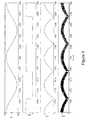
- FIG. 3shows waveforms of the synchronisation block, the reference current, the output current and the grid voltage of FIG. 2 .
- FIG. 4shows functions of the microcontroller unit of FIG. 2 .
- a power conditioning unitto inject power from a photovoltaic panel or a fuel cell into the grid in a safe, efficient, and reliable manner.
- a single-phase low-power converteris presented hereby that features a simple control that can be implemented with inexpensive logic gates and op-amps.
- a basic microcontrolleris used to measure environment variables such as voltages, currents, and temperature in order to comply with standards, and to coordinate the connection with the grid.
- the PCU topologyincludes a generic dc-ac-dc that provides voltage amplification and isolation, as it is required in some regulations and a current source inverter (CSI) connected to the mains.
- the current injectionis regulated using current-mode-control in the inductor of the CSI via an intermediate buck-type stage.
- the dc-link voltageis maintained above the grid voltage magnitude via a dc-ac-dc converter with isolation transformer.
- This stageis controlled in open loop and hence the voltage appearing at the dc-link is that of the source amplified by the turns ratio of the transformer.
- Various generic topologiescan be used for this purpose and therefore this block is considered here only as a voltage amplifier.
- buck circuitfeaturing current-mode-control (CMC) in conjunction with a current source inverter (CSI) switching at 50 Hz in synchronism with the grid as will be explained.
- CMCcurrent-mode-control
- CSIcurrent source inverter
- a power conditioning unit for single-phase grid-connected distributed resourcesis shown in FIG. 1 . It comprises a generic dc-ac-dc converter that steps up or amplifies the voltage of the source to a voltage level above the grid voltage magnitude.
- a generic dc-ac-dc converterthat steps up or amplifies the voltage of the source to a voltage level above the grid voltage magnitude.
- Full-bridge inverter and full-bridge rectifierpush-pull converter, flyback converter, feed-forward converter, resonant converter with transformer.
- the output of this converteris connected to a filter that prevents the flow of high frequency components in current and voltage.
- the input and output of this filterform what is called de-link as depicted in FIG. 1 .
- transistors Q 1 to Q 5diodes D 1 to D 6 , inductor L out , capacitor C out , and the current sensor.
- the grid voltage terminals from the residential outlet, line and neutral,are connected in parallel with capacitor C out .
- the line terminalis connected at the node between diodes D 1 and D 3
- the neutral terminalis connected at the node between diodes D 2 and D 4 .
- Transistors Q 1 and Q 4are switched on during the positive half cycle of the grid voltage waveform and Q 2 and Q 3 during the negative half cycle.
- Diodes D 1 -D 4prevent a short circuit in the grid due to glitches in the transistor drivers that might result in destruction of the converter.
- the transistors in each pairQ 1 and Q 4 , Q 2 and Q 3 ) to change state at exactly the same time. If, for example, Q 1 and Q 4 are switched off and Q 3 is switched on but Q 2 has not yet been switched on, a current may flow from the line grid terminal through Q 3 and back through the body diode of Q 4 to the neutral grid terminal.
- diodes D 1 -D 4prevents grid currents flowing through the body diodes, hence prolonging the lifespan of the converter. Although these diodes reduce the overall efficiency of the converter they improve the reliability since they protect the transistors.
- D 6acts as a free-wheeling diode and D 5 prevents current form flowing back into the dc-link.
- transistor Q 5When transistor Q 5 is switched on, a current builds up through L out . When Q 5 is switched off, this current cannot return to zero immediately so D 6 provides an alternative path for current to flow from the negative supply rail. Because of the body diode in Q 5 , it might be possible for a current to flow back into the do-link when Q 5 is switched off; D 5 prevents this happening.
- the current injection into the gridis controlled using transistor Q 5 .
- Q 5When Q 5 is turned on the current flowing through L out increases and decreases when it is turned off thus achieving current-mode-control. This is always true as long as the dc-link voltage is maintained higher than the grid voltage magnitude. Hence the current is forced to follow a rectified sinusoid which is in turn unfolded by the full-bridge output (transistors Q 1 to Q 4 ).
- the information from the current sensoris used to feedback the instantaneous current value to the control circuits.
- the current injectionis controlled using CMC.
- the inductor current, i outis compared to a reference current, i ref , to decide whether or not to switch on transistor Q 5 . If the reference current is higher than t out then the transistor is turned on. It is switched off otherwise.
- the decisionis buffered and stored using a D flip-flop with a clock signal (CLK) in the range of 100 kHz to 500 kHz.
- CLKclock signal
- the Plant block in FIG. 2is formed by transistors Q 1 to Q 5 , diodes D 1 to D 6 , inductor L out , capacitor C out , and the current sensor.
- a driveris a circuit that provides the right voltage and current levels necessary to turn on or off a specific transistor.
- the Synchronisation blockprovides digital signals in synchronism with the grid voltage, i.e. a high level when the grid voltage is positive and a low level otherwise.
- the Sine generatorprovides an almost pure sinusoid voltage in synchronism with a signal coming from the Synchronisation block. This can be achieved in various ways. The simplest approach is to sense the voltage from the grid terminals using a high-common mode differential operational amplifier.
- any distortion in the mainsis carried on as distortion in the current waveform.
- Another wayis to use a waveform generator and a phase-lock-loop so that both waveforms are in synchronism. Integrated circuits that accomplish this task normally provide waveforms with a THD between 3 and 5%.
- a third wayis to generate it digitally using a look-up table and a digital to analogue converter. Minimum distortion can be achieved by having a large resolution, e.g. 12 bits, and a fast sampling rate, e.g. 500 KHz.
- This sinusoidal voltageis rectified by an additional circuit.
- the blocks Rectifier and Sine generatorcan be combined into a single block that performs both actions simultaneously.
- a look-up tablemay be used comprising a rectified sinusoid waveform, or the first half of a sinusoid output at twice the frequency of the grid voltage.
- One additional possibilityis to clock the D flip-flop used to buffer the output of the comparator at the same high frequency used to step through the look-up table. This is possible since the output of the comparator is read into the flip-flop at discrete intervals, so the reference current input to the comparator may be updated at the same frequency.
- the MCU blockcontains a microcontroller unit and the DAC block contains a digital to analogue converter circuit.
- the reference current, i refis generated by multiplying a constant voltage, from the DAC, by a rectified sinusoidal template, from the Rectifier (or equivalent circuit as described above), in synchronism with the electric grid voltage.
- the constant voltage coming from the digital to analogue converter (DAC)provides the amplitude of the reference current and therefore the power injection level. This is controlled from the microcontroller unit (MCU).
- the comparison between the reference current and the sensed currentis done through a high speed comparator integrated circuit or operational amplifier.
- Waveforms of the synchronisation block, the reference current, the output current and the grid voltageare shown in FIG. 3 .
- the MCUmonitors the temperature of the system, the grid voltage magnitude, the grid voltage frequency, and incorporates communication protocols for external monitoring through a computer. These tasks are depicted in FIG. 4 .
Landscapes
- Engineering & Computer Science (AREA)
- Power Engineering (AREA)
- Inverter Devices (AREA)
- Dc-Dc Converters (AREA)
- Rectifiers (AREA)
- Power Conversion In General (AREA)
Abstract
Description
Claims (11)
Priority Applications (3)
| Application Number | Priority Date | Filing Date | Title |
|---|---|---|---|
| US14/542,386US9473038B2 (en) | 2004-11-08 | 2014-11-14 | Power conditioning unit with voltage converters |
| US15/264,573US9831794B2 (en) | 2004-11-08 | 2016-09-13 | Power conditioning unit with voltage converters |
| US15/807,540US10033292B2 (en) | 2004-11-08 | 2017-11-08 | Power conditioning unit with voltage converters |
Applications Claiming Priority (6)
| Application Number | Priority Date | Filing Date | Title |
|---|---|---|---|
| GB0424556.9 | 2004-11-08 | ||
| GB0424556AGB2415841B (en) | 2004-11-08 | 2004-11-08 | Power conditioning unit |
| PCT/GB2005/050197WO2006048688A1 (en) | 2004-11-08 | 2005-11-04 | Power conditioning unit |
| US71887909A | 2009-05-21 | 2009-05-21 | |
| US13/748,375US8971082B2 (en) | 2004-11-08 | 2013-01-23 | Power conditioning unit with voltage converters |
| US14/542,386US9473038B2 (en) | 2004-11-08 | 2014-11-14 | Power conditioning unit with voltage converters |
Related Parent Applications (1)
| Application Number | Title | Priority Date | Filing Date |
|---|---|---|---|
| US13/748,375ContinuationUS8971082B2 (en) | 2004-11-08 | 2013-01-23 | Power conditioning unit with voltage converters |
Related Child Applications (1)
| Application Number | Title | Priority Date | Filing Date |
|---|---|---|---|
| US15/264,573ContinuationUS9831794B2 (en) | 2004-11-08 | 2016-09-13 | Power conditioning unit with voltage converters |
Publications (2)
| Publication Number | Publication Date |
|---|---|
| US20150236604A1 US20150236604A1 (en) | 2015-08-20 |
| US9473038B2true US9473038B2 (en) | 2016-10-18 |
Family
ID=33523287
Family Applications (5)
| Application Number | Title | Priority Date | Filing Date |
|---|---|---|---|
| US11/718,879Expired - Fee RelatedUS8369113B2 (en) | 2004-11-08 | 2005-11-04 | Power conditioning unit |
| US13/748,375ActiveUS8971082B2 (en) | 2004-11-08 | 2013-01-23 | Power conditioning unit with voltage converters |
| US14/542,386ActiveUS9473038B2 (en) | 2004-11-08 | 2014-11-14 | Power conditioning unit with voltage converters |
| US15/264,573ActiveUS9831794B2 (en) | 2004-11-08 | 2016-09-13 | Power conditioning unit with voltage converters |
| US15/807,540ActiveUS10033292B2 (en) | 2004-11-08 | 2017-11-08 | Power conditioning unit with voltage converters |
Family Applications Before (2)
| Application Number | Title | Priority Date | Filing Date |
|---|---|---|---|
| US11/718,879Expired - Fee RelatedUS8369113B2 (en) | 2004-11-08 | 2005-11-04 | Power conditioning unit |
| US13/748,375ActiveUS8971082B2 (en) | 2004-11-08 | 2013-01-23 | Power conditioning unit with voltage converters |
Family Applications After (2)
| Application Number | Title | Priority Date | Filing Date |
|---|---|---|---|
| US15/264,573ActiveUS9831794B2 (en) | 2004-11-08 | 2016-09-13 | Power conditioning unit with voltage converters |
| US15/807,540ActiveUS10033292B2 (en) | 2004-11-08 | 2017-11-08 | Power conditioning unit with voltage converters |
Country Status (3)
| Country | Link |
|---|---|
| US (5) | US8369113B2 (en) |
| GB (1) | GB2415841B (en) |
| WO (1) | WO2006048688A1 (en) |
Cited By (1)
| Publication number | Priority date | Publication date | Assignee | Title |
|---|---|---|---|---|
| US9831798B2 (en)* | 2015-04-28 | 2017-11-28 | Kabushiki Kaisha Yaskawa Denki | Power conversion apparatus, power generation system, and control method |
Families Citing this family (105)
| Publication number | Priority date | Publication date | Assignee | Title |
|---|---|---|---|---|
| DE202004021675U1 (en) | 2003-05-06 | 2010-05-12 | Enecsys Ltd., Cambridge | Power supply circuits |
| GB2415841B (en) | 2004-11-08 | 2006-05-10 | Enecsys Ltd | Power conditioning unit |
| US10693415B2 (en) | 2007-12-05 | 2020-06-23 | Solaredge Technologies Ltd. | Testing of a photovoltaic panel |
| US11881814B2 (en) | 2005-12-05 | 2024-01-23 | Solaredge Technologies Ltd. | Testing of a photovoltaic panel |
| US8405367B2 (en) | 2006-01-13 | 2013-03-26 | Enecsys Limited | Power conditioning units |
| GB2434490B (en) | 2006-01-13 | 2009-04-01 | Enecsys Ltd | Power conditioning unit |
| WO2008015298A1 (en)* | 2006-07-31 | 2008-02-07 | Ingeteam Energy, S.A. | Single-phase inverter circuit for conditioning and converting dc electrical energy into ac electrical energy |
| US8013472B2 (en) | 2006-12-06 | 2011-09-06 | Solaredge, Ltd. | Method for distributed power harvesting using DC power sources |
| US8384243B2 (en) | 2007-12-04 | 2013-02-26 | Solaredge Technologies Ltd. | Distributed power harvesting systems using DC power sources |
| US8963369B2 (en) | 2007-12-04 | 2015-02-24 | Solaredge Technologies Ltd. | Distributed power harvesting systems using DC power sources |
| US9130401B2 (en) | 2006-12-06 | 2015-09-08 | Solaredge Technologies Ltd. | Distributed power harvesting systems using DC power sources |
| US8319483B2 (en) | 2007-08-06 | 2012-11-27 | Solaredge Technologies Ltd. | Digital average input current control in power converter |
| US12316274B2 (en) | 2006-12-06 | 2025-05-27 | Solaredge Technologies Ltd. | Pairing of components in a direct current distributed power generation system |
| US11687112B2 (en) | 2006-12-06 | 2023-06-27 | Solaredge Technologies Ltd. | Distributed power harvesting systems using DC power sources |
| US11296650B2 (en) | 2006-12-06 | 2022-04-05 | Solaredge Technologies Ltd. | System and method for protection during inverter shutdown in distributed power installations |
| US8618692B2 (en) | 2007-12-04 | 2013-12-31 | Solaredge Technologies Ltd. | Distributed power system using direct current power sources |
| US8816535B2 (en) | 2007-10-10 | 2014-08-26 | Solaredge Technologies, Ltd. | System and method for protection during inverter shutdown in distributed power installations |
| US11309832B2 (en) | 2006-12-06 | 2022-04-19 | Solaredge Technologies Ltd. | Distributed power harvesting systems using DC power sources |
| US11569659B2 (en) | 2006-12-06 | 2023-01-31 | Solaredge Technologies Ltd. | Distributed power harvesting systems using DC power sources |
| US11735910B2 (en) | 2006-12-06 | 2023-08-22 | Solaredge Technologies Ltd. | Distributed power system using direct current power sources |
| US11888387B2 (en) | 2006-12-06 | 2024-01-30 | Solaredge Technologies Ltd. | Safety mechanisms, wake up and shutdown methods in distributed power installations |
| US9088178B2 (en) | 2006-12-06 | 2015-07-21 | Solaredge Technologies Ltd | Distributed power harvesting systems using DC power sources |
| US8473250B2 (en) | 2006-12-06 | 2013-06-25 | Solaredge, Ltd. | Monitoring of distributed power harvesting systems using DC power sources |
| US8947194B2 (en) | 2009-05-26 | 2015-02-03 | Solaredge Technologies Ltd. | Theft detection and prevention in a power generation system |
| US8319471B2 (en) | 2006-12-06 | 2012-11-27 | Solaredge, Ltd. | Battery power delivery module |
| US9112379B2 (en) | 2006-12-06 | 2015-08-18 | Solaredge Technologies Ltd. | Pairing of components in a direct current distributed power generation system |
| US11855231B2 (en) | 2006-12-06 | 2023-12-26 | Solaredge Technologies Ltd. | Distributed power harvesting systems using DC power sources |
| US7994657B2 (en) | 2006-12-22 | 2011-08-09 | Solarbridge Technologies, Inc. | Modular system for unattended energy generation and storage |
| US7755916B2 (en) | 2007-10-11 | 2010-07-13 | Solarbridge Technologies, Inc. | Methods for minimizing double-frequency ripple power in single-phase power conditioners |
| CA2737134C (en) | 2007-10-15 | 2017-10-10 | Ampt, Llc | Systems for highly efficient solar power |
| WO2009055474A1 (en) | 2007-10-23 | 2009-04-30 | And, Llc | High reliability power systems and solar power converters |
| US11264947B2 (en) | 2007-12-05 | 2022-03-01 | Solaredge Technologies Ltd. | Testing of a photovoltaic panel |
| WO2009072076A2 (en) | 2007-12-05 | 2009-06-11 | Solaredge Technologies Ltd. | Current sensing on a mosfet |
| US9291696B2 (en) | 2007-12-05 | 2016-03-22 | Solaredge Technologies Ltd. | Photovoltaic system power tracking method |
| CN105244905B (en) | 2007-12-05 | 2019-05-21 | 太阳能安吉有限公司 | Release mechanism in distributed power device is waken up and method for closing |
| WO2009073867A1 (en) | 2007-12-05 | 2009-06-11 | Solaredge, Ltd. | Parallel connected inverters |
| EP2235807B1 (en) | 2007-12-20 | 2019-05-08 | SolarCity Corporation | Grid synchronisation |
| US8111052B2 (en) | 2008-03-24 | 2012-02-07 | Solaredge Technologies Ltd. | Zero voltage switching |
| EP2294669B8 (en) | 2008-05-05 | 2016-12-07 | Solaredge Technologies Ltd. | Direct current power combiner |
| CA2655007C (en) | 2009-02-20 | 2017-06-27 | Queen's University At Kingston | Photovoltaic cell inverter |
| SG175717A1 (en) | 2009-04-17 | 2011-12-29 | Ampt Llc | Methods and apparatus for adaptive operation of solar power systems |
| EP2270971A1 (en)* | 2009-07-02 | 2011-01-05 | ABB Research Ltd. | Three-stage multilevel DC to AC converter |
| US8482947B2 (en) | 2009-07-31 | 2013-07-09 | Solarbridge Technologies, Inc. | Apparatus and method for controlling DC-AC power conversion |
| MX2012003225A (en) | 2009-09-18 | 2012-09-07 | Univ Kingston | Distributed power generation interface. |
| US8462518B2 (en) | 2009-10-12 | 2013-06-11 | Solarbridge Technologies, Inc. | Power inverter docking system for photovoltaic modules |
| US9466737B2 (en) | 2009-10-19 | 2016-10-11 | Ampt, Llc | Solar panel string converter topology |
| US12418177B2 (en) | 2009-10-24 | 2025-09-16 | Solaredge Technologies Ltd. | Distributed power system using direct current power sources |
| US8824178B1 (en) | 2009-12-31 | 2014-09-02 | Solarbridge Technologies, Inc. | Parallel power converter topology |
| GB2482653B (en) | 2010-06-07 | 2012-08-29 | Enecsys Ltd | Solar photovoltaic systems |
| US9160408B2 (en) | 2010-10-11 | 2015-10-13 | Sunpower Corporation | System and method for establishing communication with an array of inverters |
| US8503200B2 (en) | 2010-10-11 | 2013-08-06 | Solarbridge Technologies, Inc. | Quadrature-corrected feedforward control apparatus and method for DC-AC power conversion |
| US8279649B2 (en) | 2010-10-11 | 2012-10-02 | Solarbridge Technologies, Inc. | Apparatus and method for controlling a power inverter |
| US10230310B2 (en) | 2016-04-05 | 2019-03-12 | Solaredge Technologies Ltd | Safety switch for photovoltaic systems |
| US10673229B2 (en) | 2010-11-09 | 2020-06-02 | Solaredge Technologies Ltd. | Arc detection and prevention in a power generation system |
| US10673222B2 (en) | 2010-11-09 | 2020-06-02 | Solaredge Technologies Ltd. | Arc detection and prevention in a power generation system |
| GB2485527B (en) | 2010-11-09 | 2012-12-19 | Solaredge Technologies Ltd | Arc detection and prevention in a power generation system |
| US8842454B2 (en) | 2010-11-29 | 2014-09-23 | Solarbridge Technologies, Inc. | Inverter array with localized inverter control |
| US9467063B2 (en) | 2010-11-29 | 2016-10-11 | Sunpower Corporation | Technologies for interleaved control of an inverter array |
| GB2486408A (en) | 2010-12-09 | 2012-06-20 | Solaredge Technologies Ltd | Disconnection of a string carrying direct current |
| GB2496140B (en) | 2011-11-01 | 2016-05-04 | Solarcity Corp | Photovoltaic power conditioning units |
| GB2483317B (en) | 2011-01-12 | 2012-08-22 | Solaredge Technologies Ltd | Serially connected inverters |
| GB2487368B (en) | 2011-01-18 | 2012-12-05 | Enecsys Ltd | Inverters |
| GB2486509B (en) | 2011-03-22 | 2013-01-09 | Enecsys Ltd | Solar photovoltaic power conditioning units |
| US9065354B2 (en) | 2011-04-27 | 2015-06-23 | Sunpower Corporation | Multi-stage power inverter for power bus communication |
| US8193788B2 (en) | 2011-04-27 | 2012-06-05 | Solarbridge Technologies, Inc. | Method and device for controlling a configurable power supply to provide AC and/or DC power output |
| US8611107B2 (en) | 2011-04-27 | 2013-12-17 | Solarbridge Technologies, Inc. | Method and system for controlling a multi-stage power inverter |
| US8922185B2 (en) | 2011-07-11 | 2014-12-30 | Solarbridge Technologies, Inc. | Device and method for global maximum power point tracking |
| US8570005B2 (en) | 2011-09-12 | 2013-10-29 | Solaredge Technologies Ltd. | Direct current link circuit |
| US8284574B2 (en) | 2011-10-17 | 2012-10-09 | Solarbridge Technologies, Inc. | Method and apparatus for controlling an inverter using pulse mode control |
| EP2774243B1 (en) | 2011-11-01 | 2018-05-16 | SolarCity Corporation | Photovoltaic power conditioning units |
| GB2496139B (en) | 2011-11-01 | 2016-05-04 | Solarcity Corp | Photovoltaic power conditioning units |
| GB2496163B (en) | 2011-11-03 | 2015-11-11 | Enecsys Ltd | Transformer construction |
| GB2497275A (en) | 2011-11-25 | 2013-06-12 | Enecsys Ltd | Modular adjustable power factor renewable energy inverter system |
| GB2498365A (en) | 2012-01-11 | 2013-07-17 | Solaredge Technologies Ltd | Photovoltaic module |
| US9853565B2 (en) | 2012-01-30 | 2017-12-26 | Solaredge Technologies Ltd. | Maximized power in a photovoltaic distributed power system |
| GB2498791A (en) | 2012-01-30 | 2013-07-31 | Solaredge Technologies Ltd | Photovoltaic panel circuitry |
| GB2498790A (en) | 2012-01-30 | 2013-07-31 | Solaredge Technologies Ltd | Maximising power in a photovoltaic distributed power system |
| EP2634909B1 (en)* | 2012-03-02 | 2017-02-15 | ABB Research Ltd. | Method for controlling a grid-connected boost-buck full-bridge current-source inverter cascade for photovoltaic applications and device |
| GB2499991A (en) | 2012-03-05 | 2013-09-11 | Solaredge Technologies Ltd | DC link circuit for photovoltaic array |
| US10115841B2 (en) | 2012-06-04 | 2018-10-30 | Solaredge Technologies Ltd. | Integrated photovoltaic panel circuitry |
| US9276635B2 (en) | 2012-06-29 | 2016-03-01 | Sunpower Corporation | Device, system, and method for communicating with a power inverter using power line communications |
| US9225253B2 (en)* | 2012-10-23 | 2015-12-29 | Microchip Technology Inc. | High voltage switching linear amplifier and method therefor |
| US9257837B2 (en) | 2013-01-04 | 2016-02-09 | Solarcity Corporation | Power balancing in a multi-phase system |
| US9941813B2 (en) | 2013-03-14 | 2018-04-10 | Solaredge Technologies Ltd. | High frequency multi-level inverter |
| US9548619B2 (en) | 2013-03-14 | 2017-01-17 | Solaredge Technologies Ltd. | Method and apparatus for storing and depleting energy |
| US9397497B2 (en) | 2013-03-15 | 2016-07-19 | Ampt, Llc | High efficiency interleaved solar power supply system |
| US9564835B2 (en) | 2013-03-15 | 2017-02-07 | Sunpower Corporation | Inverter communications using output signal |
| EP3506370B1 (en) | 2013-03-15 | 2023-12-20 | Solaredge Technologies Ltd. | Bypass mechanism |
| US9584044B2 (en) | 2013-03-15 | 2017-02-28 | Sunpower Corporation | Technologies for converter topologies |
| US9882507B2 (en) | 2013-04-16 | 2018-01-30 | Solarcity Corporation | Power factor adjustment in multi-phase power system |
| US9160252B1 (en)* | 2013-05-07 | 2015-10-13 | Rockwell Collins, Inc. | For cooling an avionics device with a fan utilizing a single phase AC motor |
| US9602025B2 (en)* | 2013-07-12 | 2017-03-21 | Infineon Technologies Austria Ag | Multiphase power converter circuit and method |
| JP6176121B2 (en)* | 2014-01-10 | 2017-08-09 | 住友電気工業株式会社 | Power converter and three-phase AC power supply |
| US9318974B2 (en) | 2014-03-26 | 2016-04-19 | Solaredge Technologies Ltd. | Multi-level inverter with flying capacitor topology |
| WO2015152745A1 (en)* | 2014-04-05 | 2015-10-08 | Inov Inesc Inovação Instituto De Novas Tecnologias | Electronic energy conversion circuit, energy arrangement presenting said circuit and process of operation of said circuit |
| JP6620629B2 (en)* | 2016-03-24 | 2019-12-18 | 住友電気工業株式会社 | Power conversion apparatus and control method thereof |
| US11177663B2 (en) | 2016-04-05 | 2021-11-16 | Solaredge Technologies Ltd. | Chain of power devices |
| US12057807B2 (en) | 2016-04-05 | 2024-08-06 | Solaredge Technologies Ltd. | Chain of power devices |
| US11018623B2 (en) | 2016-04-05 | 2021-05-25 | Solaredge Technologies Ltd. | Safety switch for photovoltaic systems |
| CN105790704A (en)* | 2016-06-03 | 2016-07-20 | 浙江人和光伏科技有限公司 | Junction box for solar cell |
| US11309714B2 (en) | 2016-11-02 | 2022-04-19 | Tesla, Inc. | Micro-batteries for energy generation systems |
| US20190363642A1 (en)* | 2018-05-23 | 2019-11-28 | Fuxiang LIN | Inverter |
| WO2020097586A1 (en) | 2018-11-08 | 2020-05-14 | Guangdong Redx Electrical Technology Limited | Novel fws dc-ac grid connected inverter |
| TWI752610B (en) | 2020-09-01 | 2022-01-11 | 元太科技工業股份有限公司 | Voltage regulating circuit, voltage regulating method and display device |
| CN113364322B (en)* | 2021-05-08 | 2022-08-09 | 湖南珂拓电子科技有限公司 | Single-phase single-stage current source type inverter |
Citations (103)
| Publication number | Priority date | Publication date | Assignee | Title |
|---|---|---|---|---|
| US2852721A (en) | 1954-06-16 | 1958-09-16 | Dortmund Harder Huttenunion Ag | Glow discharge circuits |
| GB1571681A (en) | 1978-04-25 | 1980-07-16 | Itt Creed Ltd Dc Ac | Inverter |
| US4479175A (en) | 1982-08-13 | 1984-10-23 | Honeywell Inc. | Phase modulated switchmode power amplifier and waveform generator |
| US4626983A (en) | 1983-10-06 | 1986-12-02 | Nishimu Electronics Industries Co., Ltd. | Power conversion device for solar cell |
| US4772994A (en) | 1987-09-10 | 1988-09-20 | Nishimu Electronics Industries, Co., Ltd. | Power source using high-frequency phase control |
| JPH01311874A (en) | 1988-06-09 | 1989-12-15 | Matsushita Electric Ind Co Ltd | Ac power source device |
| JPH053678A (en) | 1991-06-25 | 1993-01-08 | Toshiba F Ee Syst Eng Kk | Dc/ac power supply |
| US5268832A (en) | 1991-08-20 | 1993-12-07 | Kabushiki Kaisha Toshiba | DC/AC inverter controller for solar cell, including maximum power point tracking function |
| US5329222A (en) | 1992-11-30 | 1994-07-12 | Westinghouse Electric Corporation | Apparatus and method for dynamic voltage restoration of utility distribution networks |
| EP0628901A2 (en) | 1993-06-11 | 1994-12-14 | Canon Kabushiki Kaisha | Power control apparatus and method and power generating system using them |
| US5379209A (en) | 1993-02-09 | 1995-01-03 | Performance Controls, Inc. | Electronic switching circuit |
| US5381327A (en) | 1992-03-19 | 1995-01-10 | Astec International, Ltd. | Electrical power inverter |
| JPH0728538A (en) | 1993-07-14 | 1995-01-31 | Sharp Corp | Grid-connected inverter controller |
| US5404059A (en) | 1992-03-19 | 1995-04-04 | Abb Patent Gmbh | Circuit for driving a voltage-controlled semiconductor switch |
| US5442538A (en) | 1993-01-07 | 1995-08-15 | Mitsubishi Denki Kabushiki Kaisha | Apparatus for controlling power converter based on output current |
| US5504449A (en) | 1992-04-09 | 1996-04-02 | Harris Corporation | Power driver circuit |
| JPH08227324A (en) | 1995-02-20 | 1996-09-03 | Omron Corp | Photovoltaic power generator |
| US5576941A (en) | 1994-08-10 | 1996-11-19 | York Technologies, Inc. | Modular power supply system |
| JPH08317664A (en) | 1995-05-17 | 1996-11-29 | Yaskawa Electric Corp | System overvoltage protection method for photovoltaic power converters |
| US5585749A (en) | 1994-12-27 | 1996-12-17 | Motorola, Inc. | High current driver providing battery overload protection |
| EP0780750A2 (en) | 1995-12-20 | 1997-06-25 | Sharp Kabushiki Kaisha | Inventer control method and inventer apparatus using the method |
| JPH10174452A (en) | 1996-12-10 | 1998-06-26 | Omron Corp | Power conversion device, inverter and photovoltaic power generation system |
| US5814970A (en) | 1994-07-30 | 1998-09-29 | Fraunhofer-Gesellschaft Zur Forderung Der Angewandten Forschung E.V. | Apparatus for charge exchange among a plurality of series connected energy accumulators or energy converters |
| DE19732218C1 (en) | 1997-07-26 | 1999-03-18 | Dirk Schekulin | Transformerless ac. inverter circuit, for coupling photovoltaic systems or wind generator systems, esp. in the low power range, to current networks |
| US5898585A (en) | 1997-05-29 | 1999-04-27 | Premier Global Corporation, Ltd. | Apparatus and method for providing supplemental alternating current from a solar cell array |
| US5930131A (en) | 1998-05-28 | 1999-07-27 | Long Well Electronics Corp. | Controlling device for conversion of DC power to sine wave AC power |
| EP0947905A2 (en) | 1998-03-30 | 1999-10-06 | Sanyo Electric Co. Ltd | Solar power generating device |
| JP2000020150A (en) | 1998-06-30 | 2000-01-21 | Toshiba Fa Syst Eng Corp | Solar power inverter |
| US6021052A (en) | 1997-09-22 | 2000-02-01 | Statpower Technologies Partnership | DC/AC power converter |
| US6058035A (en) | 1998-03-30 | 2000-05-02 | Sanyo Electric Co., Ltd. | Method and apparatus for supplying AC power to commercial power line by using sunlight |
| US6081104A (en) | 1998-11-20 | 2000-06-27 | Applied Power Corporation | Method and apparatus for providing energy to a lighting system |
| US6111767A (en) | 1998-06-22 | 2000-08-29 | Heliotronics, Inc. | Inverter integrated instrumentation having a current-voltage curve tracer |
| JP2000316282A (en) | 1999-04-28 | 2000-11-14 | Toshiba Fa Syst Eng Corp | Power conditioner for photovoltaic power generation |
| JP2000324852A (en) | 1999-05-14 | 2000-11-24 | Sanyo Electric Co Ltd | Current type inverter for photovoltaic power generation |
| DE19937410A1 (en) | 1999-08-07 | 2001-02-15 | Elektro & Automatisierungstech | Three-phase solar converter for mains and island power operations adapts voltage levels from DC voltage generated by solar cells to the public mains power supply by raising and converting power. |
| US6211657B1 (en) | 2000-05-18 | 2001-04-03 | Communications & Power Industries, Inc. | Two stage power converter with interleaved buck regulators |
| US6330170B1 (en)* | 1999-08-27 | 2001-12-11 | Virginia Tech Intellectual Properties, Inc. | Soft-switched quasi-single-stage (QSS) bi-directional inverter/charger |
| DE10064039A1 (en) | 2000-05-24 | 2001-12-20 | Mitsubishi Electric Corp | Discharge lamp switch-on arrangement e.g. for motor vehicle applications, has input of switching circuit connected to output via field effect transistor (FET) |
| US20020034083A1 (en) | 1999-09-01 | 2002-03-21 | Rajapandian Ayyanar | Zero voltage switching DC-DC converter |
| US6369461B1 (en) | 2000-09-01 | 2002-04-09 | Abb Inc. | High efficiency power conditioner employing low voltage DC bus and buck and boost converters |
| US20020085397A1 (en) | 2000-11-27 | 2002-07-04 | Masaki Suzui | Power converting apparatus, control method therefor, and power generation system |
| EP1235339A2 (en) | 2001-02-26 | 2002-08-28 | Canon Kabushiki Kaisha | Inverter, power supply system and method of reducing leakage current in power supply system |
| US6445599B1 (en) | 2001-03-29 | 2002-09-03 | Maxim Integrated Products, Inc. | Ripple canceling, soft switching isolated DC/DC converters with reduced voltage stress synchronous rectification |
| EP1239576A2 (en) | 2001-03-09 | 2002-09-11 | National Institute of Advanced Industrial Science and Technology | Maximum power point tracking method and device |
| US20020149950A1 (en) | 2001-04-13 | 2002-10-17 | Tsukasa Takebayashi | Power conditioner for solar power generation system |
| US20030038615A1 (en) | 2001-08-23 | 2003-02-27 | Fairchild Semiconductor Corporation | Method and circuit for reducing losses in DC-DC converters |
| US20030080741A1 (en) | 2001-10-26 | 2003-05-01 | Lerow Kevin E. | Anti-islanding techniques for distributed power generation |
| JP2003289674A (en) | 2002-03-27 | 2003-10-10 | Tama Tlo Kk | Inverter circuit and photovoltaic generator |
| US20030193821A1 (en) | 2002-04-10 | 2003-10-16 | Michael Krieger | Inverter for producing a true sine wave |
| US6657419B2 (en) | 2001-11-19 | 2003-12-02 | Solarmate Corporation | Micro-solar insolation circuit |
| US6690592B2 (en)* | 2001-05-17 | 2004-02-10 | Siemens Aktiengesellschaft | Inverter with a self-commutated pulse converter on the line side and the load side |
| US20040076028A1 (en) | 2001-03-09 | 2004-04-22 | Gunter Achleitner | Method for regulating an inverter system |
| US20040165408A1 (en) | 2003-02-21 | 2004-08-26 | Mr.Rick West | Dc to ac inverter with single-switch bipolar boost circuit |
| US6791850B2 (en) | 2001-10-23 | 2004-09-14 | Delta Electronics, Inc. | DC-to-AC power inverter and method of operation thereof |
| US20040207366A1 (en) | 2003-04-21 | 2004-10-21 | Phoenixtec Power Co., Ltd. | Multi-mode renewable power converter system |
| US20040217742A1 (en)* | 2003-03-18 | 2004-11-04 | Ribarich Thomas J. | High intensity discharge lamp ballast circuit |
| WO2004100348A1 (en) | 2003-05-06 | 2004-11-18 | Enecsys Limited | Power supply circuits |
| US20040233685A1 (en) | 2003-02-06 | 2004-11-25 | Matsushita Electric Industrial Co., Ltd. | Switching power supply |
| US20050030772A1 (en) | 2003-08-08 | 2005-02-10 | Phadke Vijay Gangadhar | Circuit for maintaining hold-up time while reducing bulk capacitor size and improving efficiency in a power supply |
| US6856102B1 (en) | 2004-05-14 | 2005-02-15 | Hitech Electronics Co., Ltd. | Three-stage electronic ballast for metal halide lamps |
| US6888728B2 (en) | 2001-05-25 | 2005-05-03 | Tdk Corporation | Switching power supply unit |
| US20050242795A1 (en) | 2001-08-22 | 2005-11-03 | Shihab Al-Kuran | MMIC DC-to-DC converter |
| US6980783B2 (en)* | 2002-05-31 | 2005-12-27 | Ciena Corporation | Apparatus and method of controlling low frequency load currents drawn from a DC source in a telecommunications system |
| GB2415841A (en) | 2004-11-08 | 2006-01-04 | Enecsys Ltd | Power conditioning unit for connecting dc source to a mains utility supply |
| US7031176B2 (en) | 2002-07-15 | 2006-04-18 | Koninklijke Philips Electronics N.V. | Inverter |
| US7064967B2 (en) | 2003-02-28 | 2006-06-20 | Hitachi, Ltd. | Fuel cell system and control method |
| US7078883B2 (en) | 2004-04-07 | 2006-07-18 | The Board Of Trustees Of The University Of Illinois | Method and apparatus for starting power converters |
| US20060232220A1 (en) | 2005-04-13 | 2006-10-19 | Ballastronic, Inc. | Low frequency electronic ballast for gas discharge lamps |
| US7158395B2 (en) | 2003-05-02 | 2007-01-02 | Ballard Power Systems Corporation | Method and apparatus for tracking maximum power point for inverters, for example, in photovoltaic applications |
| US20070035975A1 (en) | 2005-08-10 | 2007-02-15 | Distributed Power, Inc. | Photovoltaic dc-to-ac power converter and control method |
| US7193872B2 (en) | 2005-01-28 | 2007-03-20 | Kasemsan Siri | Solar array inverter with maximum power tracking |
| US7262979B2 (en) | 2004-06-09 | 2007-08-28 | Yuan Ze University | Current source wave voltage inverter voltage-clamping and soft-switching techniques, and fuel cell system using the same |
| WO2007124518A1 (en) | 2006-04-27 | 2007-11-08 | Fronius International Gmbh | Bridging of a stepdown controller in a converter of a solar unit |
| US20070290656A1 (en) | 2006-06-16 | 2007-12-20 | Astec Custom Power ( Hk) Ltd. | Zero voltage zero current switching converter |
| US7339287B2 (en) | 2002-06-23 | 2008-03-04 | Powerlynx A/S | Power converter |
| US20080055941A1 (en) | 2005-05-20 | 2008-03-06 | Sma Technologie Ag | Inverter |
| US20080164766A1 (en) | 2006-12-06 | 2008-07-10 | Meir Adest | Current bypass for distributed power harvesting systems using dc power sources |
| US7414870B2 (en) | 2005-02-26 | 2008-08-19 | Kostal Industrie Elektrik Gmbh | Inverter |
| US20080205096A1 (en) | 2007-02-22 | 2008-08-28 | Jih-Sheng Lai | Control system and method for a universal power conditioning system |
| US20080266919A1 (en) | 2007-03-13 | 2008-10-30 | Sma Technologie Ag | Circuit apparatus for transformerless conversion of an electric direct voltage into an alternating voltage |
| US7450401B2 (en) | 2005-10-17 | 2008-11-11 | Kabushiki Kaisha Toyota Jidoshokki | Bidirectional DC/AC inverter |
| US20080285317A1 (en) | 2007-05-17 | 2008-11-20 | Larankelo, Inc. | Photovoltaic module-mounted ac inverter |
| US20080291707A1 (en) | 2007-05-23 | 2008-11-27 | Hamilton Sundstrand Corporation | Universal AC high power inveter with galvanic isolation for linear and non-linear loads |
| US7463500B2 (en) | 2003-02-21 | 2008-12-09 | Xantrex Technology, Inc. | Monopolar DC to bipolar DC to AC converter |
| US20080304298A1 (en) | 2006-03-27 | 2008-12-11 | Mitsubishi Electric Corporation | System Interconnection Inverter |
| US20080304296A1 (en) | 2007-06-06 | 2008-12-11 | General Electric Company | DC-DC and DC-AC power conversion system |
| US7466566B2 (en) | 2004-03-05 | 2008-12-16 | Rohm Co., Ltd. | DC-AC converter, controller IC therefor, and electronic apparatus utilizing such DC-AC converter |
| US7479774B2 (en) | 2006-04-07 | 2009-01-20 | Yuan Ze University | High-performance solar photovoltaic (PV) energy conversion system |
| US7502242B2 (en)* | 2005-10-19 | 2009-03-10 | Kabushiki Kaisha Toyota Jidoshokki | Bidirectional insulated DC/AC inverter |
| US20090097283A1 (en) | 2007-10-11 | 2009-04-16 | Krein Philip T | Methods for Minimizing Double-Frequency Ripple Power in Single-Phase Power Conditioners |
| US7525256B2 (en)* | 2004-10-29 | 2009-04-28 | International Rectifier Corporation | HID buck and full-bridge ballast control IC |
| US20090140577A1 (en) | 2007-11-30 | 2009-06-04 | Fishman Oleg S | Multiphase Grid Synchronized Regulated Current Source Inverter Systems |
| WO2009134756A1 (en) | 2008-04-29 | 2009-11-05 | Cirrus Logic, Inc. | Cascaded switching power converter for coupling a photovoltaic energy source to power mains |
| US20100157632A1 (en) | 2008-12-20 | 2010-06-24 | Azuray Technologies, Inc. | Energy Conversion Systems With Power Control |
| US20100195361A1 (en) | 2009-01-30 | 2010-08-05 | Michael Joseph Stem | Photovoltaic power plant with distributed DC-to-DC power converters |
| US20100207455A1 (en) | 2009-02-13 | 2010-08-19 | Miasole | Thin-film photovoltaic power element with integrated low-profile high-efficiency DC-DC converter |
| US7885085B2 (en) | 2007-01-22 | 2011-02-08 | Power Integrations, Inc. | Cascaded PFC and resonant mode power converters |
| US20110273015A1 (en) | 2006-12-06 | 2011-11-10 | Solaredge Technologies Ltd. | Distributed power harvesting systems using dc power sources |
| US8067855B2 (en) | 2003-05-06 | 2011-11-29 | Enecsys Limited | Power supply circuits |
| US8139382B2 (en) | 2008-05-14 | 2012-03-20 | National Semiconductor Corporation | System and method for integrating local maximum power point tracking into an energy generating system having centralized maximum power point tracking |
| GB2487368A (en) | 2011-01-18 | 2012-07-25 | Enecsys Ltd | A photovoltaic power conditioning unit |
| GB2487495A (en) | 2011-01-18 | 2012-07-25 | Enecsys Ltd | Power conditioner with multiple capacitor banks |
| US8811047B2 (en) | 2006-01-13 | 2014-08-19 | Enecsys Limited | Solar power conditioning unit |
Family Cites Families (1)
| Publication number | Priority date | Publication date | Assignee | Title |
|---|---|---|---|---|
| US7417336B2 (en)* | 2004-08-31 | 2008-08-26 | Caterpillar Inc. | Combination current hysteresis and voltage hysteresis control for a power converter |
- 2004
- 2004-11-08GBGB0424556Apatent/GB2415841B/ennot_activeExpired - Lifetime
- 2005
- 2005-11-04USUS11/718,879patent/US8369113B2/ennot_activeExpired - Fee Related
- 2005-11-04WOPCT/GB2005/050197patent/WO2006048688A1/enactiveApplication Filing
- 2013
- 2013-01-23USUS13/748,375patent/US8971082B2/enactiveActive
- 2014
- 2014-11-14USUS14/542,386patent/US9473038B2/enactiveActive
- 2016
- 2016-09-13USUS15/264,573patent/US9831794B2/enactiveActive
- 2017
- 2017-11-08USUS15/807,540patent/US10033292B2/enactiveActive
Patent Citations (114)
| Publication number | Priority date | Publication date | Assignee | Title |
|---|---|---|---|---|
| US2852721A (en) | 1954-06-16 | 1958-09-16 | Dortmund Harder Huttenunion Ag | Glow discharge circuits |
| GB1571681A (en) | 1978-04-25 | 1980-07-16 | Itt Creed Ltd Dc Ac | Inverter |
| US4479175A (en) | 1982-08-13 | 1984-10-23 | Honeywell Inc. | Phase modulated switchmode power amplifier and waveform generator |
| US4626983A (en) | 1983-10-06 | 1986-12-02 | Nishimu Electronics Industries Co., Ltd. | Power conversion device for solar cell |
| US4772994A (en) | 1987-09-10 | 1988-09-20 | Nishimu Electronics Industries, Co., Ltd. | Power source using high-frequency phase control |
| JPH01311874A (en) | 1988-06-09 | 1989-12-15 | Matsushita Electric Ind Co Ltd | Ac power source device |
| JPH053678A (en) | 1991-06-25 | 1993-01-08 | Toshiba F Ee Syst Eng Kk | Dc/ac power supply |
| US5268832A (en) | 1991-08-20 | 1993-12-07 | Kabushiki Kaisha Toshiba | DC/AC inverter controller for solar cell, including maximum power point tracking function |
| US5381327A (en) | 1992-03-19 | 1995-01-10 | Astec International, Ltd. | Electrical power inverter |
| US5404059A (en) | 1992-03-19 | 1995-04-04 | Abb Patent Gmbh | Circuit for driving a voltage-controlled semiconductor switch |
| US5504449A (en) | 1992-04-09 | 1996-04-02 | Harris Corporation | Power driver circuit |
| US5329222A (en) | 1992-11-30 | 1994-07-12 | Westinghouse Electric Corporation | Apparatus and method for dynamic voltage restoration of utility distribution networks |
| US5442538A (en) | 1993-01-07 | 1995-08-15 | Mitsubishi Denki Kabushiki Kaisha | Apparatus for controlling power converter based on output current |
| US5379209A (en) | 1993-02-09 | 1995-01-03 | Performance Controls, Inc. | Electronic switching circuit |
| EP0628901A2 (en) | 1993-06-11 | 1994-12-14 | Canon Kabushiki Kaisha | Power control apparatus and method and power generating system using them |
| JPH0728538A (en) | 1993-07-14 | 1995-01-31 | Sharp Corp | Grid-connected inverter controller |
| US5814970A (en) | 1994-07-30 | 1998-09-29 | Fraunhofer-Gesellschaft Zur Forderung Der Angewandten Forschung E.V. | Apparatus for charge exchange among a plurality of series connected energy accumulators or energy converters |
| US5576941A (en) | 1994-08-10 | 1996-11-19 | York Technologies, Inc. | Modular power supply system |
| US5585749A (en) | 1994-12-27 | 1996-12-17 | Motorola, Inc. | High current driver providing battery overload protection |
| JPH08227324A (en) | 1995-02-20 | 1996-09-03 | Omron Corp | Photovoltaic power generator |
| JPH08317664A (en) | 1995-05-17 | 1996-11-29 | Yaskawa Electric Corp | System overvoltage protection method for photovoltaic power converters |
| EP0780750A2 (en) | 1995-12-20 | 1997-06-25 | Sharp Kabushiki Kaisha | Inventer control method and inventer apparatus using the method |
| JPH10174452A (en) | 1996-12-10 | 1998-06-26 | Omron Corp | Power conversion device, inverter and photovoltaic power generation system |
| US5898585A (en) | 1997-05-29 | 1999-04-27 | Premier Global Corporation, Ltd. | Apparatus and method for providing supplemental alternating current from a solar cell array |
| DE19732218C1 (en) | 1997-07-26 | 1999-03-18 | Dirk Schekulin | Transformerless ac. inverter circuit, for coupling photovoltaic systems or wind generator systems, esp. in the low power range, to current networks |
| US6021052A (en) | 1997-09-22 | 2000-02-01 | Statpower Technologies Partnership | DC/AC power converter |
| EP0947905A2 (en) | 1998-03-30 | 1999-10-06 | Sanyo Electric Co. Ltd | Solar power generating device |
| US6058035A (en) | 1998-03-30 | 2000-05-02 | Sanyo Electric Co., Ltd. | Method and apparatus for supplying AC power to commercial power line by using sunlight |
| US5930131A (en) | 1998-05-28 | 1999-07-27 | Long Well Electronics Corp. | Controlling device for conversion of DC power to sine wave AC power |
| US6111767A (en) | 1998-06-22 | 2000-08-29 | Heliotronics, Inc. | Inverter integrated instrumentation having a current-voltage curve tracer |
| US6339538B1 (en) | 1998-06-22 | 2002-01-15 | Clayton Kling Philips Handleman | Inverter circuit and method of operation |
| JP2000020150A (en) | 1998-06-30 | 2000-01-21 | Toshiba Fa Syst Eng Corp | Solar power inverter |
| US6081104A (en) | 1998-11-20 | 2000-06-27 | Applied Power Corporation | Method and apparatus for providing energy to a lighting system |
| JP2000316282A (en) | 1999-04-28 | 2000-11-14 | Toshiba Fa Syst Eng Corp | Power conditioner for photovoltaic power generation |
| JP2000324852A (en) | 1999-05-14 | 2000-11-24 | Sanyo Electric Co Ltd | Current type inverter for photovoltaic power generation |
| DE19937410A1 (en) | 1999-08-07 | 2001-02-15 | Elektro & Automatisierungstech | Three-phase solar converter for mains and island power operations adapts voltage levels from DC voltage generated by solar cells to the public mains power supply by raising and converting power. |
| US6330170B1 (en)* | 1999-08-27 | 2001-12-11 | Virginia Tech Intellectual Properties, Inc. | Soft-switched quasi-single-stage (QSS) bi-directional inverter/charger |
| US20020034083A1 (en) | 1999-09-01 | 2002-03-21 | Rajapandian Ayyanar | Zero voltage switching DC-DC converter |
| US6211657B1 (en) | 2000-05-18 | 2001-04-03 | Communications & Power Industries, Inc. | Two stage power converter with interleaved buck regulators |
| DE10064039A1 (en) | 2000-05-24 | 2001-12-20 | Mitsubishi Electric Corp | Discharge lamp switch-on arrangement e.g. for motor vehicle applications, has input of switching circuit connected to output via field effect transistor (FET) |
| US6369461B1 (en) | 2000-09-01 | 2002-04-09 | Abb Inc. | High efficiency power conditioner employing low voltage DC bus and buck and boost converters |
| US20020085397A1 (en) | 2000-11-27 | 2002-07-04 | Masaki Suzui | Power converting apparatus, control method therefor, and power generation system |
| US6678174B2 (en) | 2000-11-27 | 2004-01-13 | Canon Kabushiki Kaisha | Power converting apparatus, control method therefor, and power generation system |
| EP1235339A2 (en) | 2001-02-26 | 2002-08-28 | Canon Kabushiki Kaisha | Inverter, power supply system and method of reducing leakage current in power supply system |
| EP1239576A2 (en) | 2001-03-09 | 2002-09-11 | National Institute of Advanced Industrial Science and Technology | Maximum power point tracking method and device |
| US6950323B2 (en) | 2001-03-09 | 2005-09-27 | Fronius International Gmbh | Method for regulating an inverter system |
| US20040076028A1 (en) | 2001-03-09 | 2004-04-22 | Gunter Achleitner | Method for regulating an inverter system |
| US6445599B1 (en) | 2001-03-29 | 2002-09-03 | Maxim Integrated Products, Inc. | Ripple canceling, soft switching isolated DC/DC converters with reduced voltage stress synchronous rectification |
| US20020149950A1 (en) | 2001-04-13 | 2002-10-17 | Tsukasa Takebayashi | Power conditioner for solar power generation system |
| US6690592B2 (en)* | 2001-05-17 | 2004-02-10 | Siemens Aktiengesellschaft | Inverter with a self-commutated pulse converter on the line side and the load side |
| US6888728B2 (en) | 2001-05-25 | 2005-05-03 | Tdk Corporation | Switching power supply unit |
| US20050242795A1 (en) | 2001-08-22 | 2005-11-03 | Shihab Al-Kuran | MMIC DC-to-DC converter |
| US20030038615A1 (en) | 2001-08-23 | 2003-02-27 | Fairchild Semiconductor Corporation | Method and circuit for reducing losses in DC-DC converters |
| US6791850B2 (en) | 2001-10-23 | 2004-09-14 | Delta Electronics, Inc. | DC-to-AC power inverter and method of operation thereof |
| US20030080741A1 (en) | 2001-10-26 | 2003-05-01 | Lerow Kevin E. | Anti-islanding techniques for distributed power generation |
| US6657419B2 (en) | 2001-11-19 | 2003-12-02 | Solarmate Corporation | Micro-solar insolation circuit |
| JP2003289674A (en) | 2002-03-27 | 2003-10-10 | Tama Tlo Kk | Inverter circuit and photovoltaic generator |
| US20030193821A1 (en) | 2002-04-10 | 2003-10-16 | Michael Krieger | Inverter for producing a true sine wave |
| US6980783B2 (en)* | 2002-05-31 | 2005-12-27 | Ciena Corporation | Apparatus and method of controlling low frequency load currents drawn from a DC source in a telecommunications system |
| US7339287B2 (en) | 2002-06-23 | 2008-03-04 | Powerlynx A/S | Power converter |
| US7031176B2 (en) | 2002-07-15 | 2006-04-18 | Koninklijke Philips Electronics N.V. | Inverter |
| US20040233685A1 (en) | 2003-02-06 | 2004-11-25 | Matsushita Electric Industrial Co., Ltd. | Switching power supply |
| US7463500B2 (en) | 2003-02-21 | 2008-12-09 | Xantrex Technology, Inc. | Monopolar DC to bipolar DC to AC converter |
| US7099169B2 (en) | 2003-02-21 | 2006-08-29 | Distributed Power, Inc. | DC to AC inverter with single-switch bipolar boost circuit |
| US20040165408A1 (en) | 2003-02-21 | 2004-08-26 | Mr.Rick West | Dc to ac inverter with single-switch bipolar boost circuit |
| US7064967B2 (en) | 2003-02-28 | 2006-06-20 | Hitachi, Ltd. | Fuel cell system and control method |
| US20040217742A1 (en)* | 2003-03-18 | 2004-11-04 | Ribarich Thomas J. | High intensity discharge lamp ballast circuit |
| US20040207366A1 (en) | 2003-04-21 | 2004-10-21 | Phoenixtec Power Co., Ltd. | Multi-mode renewable power converter system |
| US7158395B2 (en) | 2003-05-02 | 2007-01-02 | Ballard Power Systems Corporation | Method and apparatus for tracking maximum power point for inverters, for example, in photovoltaic applications |
| US8067855B2 (en) | 2003-05-06 | 2011-11-29 | Enecsys Limited | Power supply circuits |
| WO2004100348A1 (en) | 2003-05-06 | 2004-11-18 | Enecsys Limited | Power supply circuits |
| US20050030772A1 (en) | 2003-08-08 | 2005-02-10 | Phadke Vijay Gangadhar | Circuit for maintaining hold-up time while reducing bulk capacitor size and improving efficiency in a power supply |
| US7466566B2 (en) | 2004-03-05 | 2008-12-16 | Rohm Co., Ltd. | DC-AC converter, controller IC therefor, and electronic apparatus utilizing such DC-AC converter |
| US7078883B2 (en) | 2004-04-07 | 2006-07-18 | The Board Of Trustees Of The University Of Illinois | Method and apparatus for starting power converters |
| US6856102B1 (en) | 2004-05-14 | 2005-02-15 | Hitech Electronics Co., Ltd. | Three-stage electronic ballast for metal halide lamps |
| US7262979B2 (en) | 2004-06-09 | 2007-08-28 | Yuan Ze University | Current source wave voltage inverter voltage-clamping and soft-switching techniques, and fuel cell system using the same |
| US7525256B2 (en)* | 2004-10-29 | 2009-04-28 | International Rectifier Corporation | HID buck and full-bridge ballast control IC |
| US8971082B2 (en) | 2004-11-08 | 2015-03-03 | Enecsys Limited | Power conditioning unit with voltage converters |
| US8369113B2 (en) | 2004-11-08 | 2013-02-05 | Enecsys Limited | Power conditioning unit |
| WO2006048688A1 (en) | 2004-11-08 | 2006-05-11 | Enecsys Limited | Power conditioning unit |
| GB2415841A (en) | 2004-11-08 | 2006-01-04 | Enecsys Ltd | Power conditioning unit for connecting dc source to a mains utility supply |
| US7193872B2 (en) | 2005-01-28 | 2007-03-20 | Kasemsan Siri | Solar array inverter with maximum power tracking |
| US7324361B2 (en) | 2005-01-28 | 2008-01-29 | Kasemsan Siri | Solar array inverter with maximum power tracking |
| US7414870B2 (en) | 2005-02-26 | 2008-08-19 | Kostal Industrie Elektrik Gmbh | Inverter |
| US20060232220A1 (en) | 2005-04-13 | 2006-10-19 | Ballastronic, Inc. | Low frequency electronic ballast for gas discharge lamps |
| US20080055941A1 (en) | 2005-05-20 | 2008-03-06 | Sma Technologie Ag | Inverter |
| US7319313B2 (en) | 2005-08-10 | 2008-01-15 | Xantrex Technology, Inc. | Photovoltaic DC-to-AC power converter and control method |
| US20070035975A1 (en) | 2005-08-10 | 2007-02-15 | Distributed Power, Inc. | Photovoltaic dc-to-ac power converter and control method |
| US7450401B2 (en) | 2005-10-17 | 2008-11-11 | Kabushiki Kaisha Toyota Jidoshokki | Bidirectional DC/AC inverter |
| US7502242B2 (en)* | 2005-10-19 | 2009-03-10 | Kabushiki Kaisha Toyota Jidoshokki | Bidirectional insulated DC/AC inverter |
| US8811047B2 (en) | 2006-01-13 | 2014-08-19 | Enecsys Limited | Solar power conditioning unit |
| US20080304298A1 (en) | 2006-03-27 | 2008-12-11 | Mitsubishi Electric Corporation | System Interconnection Inverter |
| US7479774B2 (en) | 2006-04-07 | 2009-01-20 | Yuan Ze University | High-performance solar photovoltaic (PV) energy conversion system |
| WO2007124518A1 (en) | 2006-04-27 | 2007-11-08 | Fronius International Gmbh | Bridging of a stepdown controller in a converter of a solar unit |
| US20070290656A1 (en) | 2006-06-16 | 2007-12-20 | Astec Custom Power ( Hk) Ltd. | Zero voltage zero current switching converter |
| US20080164766A1 (en) | 2006-12-06 | 2008-07-10 | Meir Adest | Current bypass for distributed power harvesting systems using dc power sources |
| US20110273015A1 (en) | 2006-12-06 | 2011-11-10 | Solaredge Technologies Ltd. | Distributed power harvesting systems using dc power sources |
| US7885085B2 (en) | 2007-01-22 | 2011-02-08 | Power Integrations, Inc. | Cascaded PFC and resonant mode power converters |
| US20080205096A1 (en) | 2007-02-22 | 2008-08-28 | Jih-Sheng Lai | Control system and method for a universal power conditioning system |
| US20080266919A1 (en) | 2007-03-13 | 2008-10-30 | Sma Technologie Ag | Circuit apparatus for transformerless conversion of an electric direct voltage into an alternating voltage |
| US20080285317A1 (en) | 2007-05-17 | 2008-11-20 | Larankelo, Inc. | Photovoltaic module-mounted ac inverter |
| US20080291707A1 (en) | 2007-05-23 | 2008-11-27 | Hamilton Sundstrand Corporation | Universal AC high power inveter with galvanic isolation for linear and non-linear loads |
| US20080304296A1 (en) | 2007-06-06 | 2008-12-11 | General Electric Company | DC-DC and DC-AC power conversion system |
| US20090097283A1 (en) | 2007-10-11 | 2009-04-16 | Krein Philip T | Methods for Minimizing Double-Frequency Ripple Power in Single-Phase Power Conditioners |
| US20090140577A1 (en) | 2007-11-30 | 2009-06-04 | Fishman Oleg S | Multiphase Grid Synchronized Regulated Current Source Inverter Systems |
| WO2009134756A1 (en) | 2008-04-29 | 2009-11-05 | Cirrus Logic, Inc. | Cascaded switching power converter for coupling a photovoltaic energy source to power mains |
| US8139382B2 (en) | 2008-05-14 | 2012-03-20 | National Semiconductor Corporation | System and method for integrating local maximum power point tracking into an energy generating system having centralized maximum power point tracking |
| US20100157632A1 (en) | 2008-12-20 | 2010-06-24 | Azuray Technologies, Inc. | Energy Conversion Systems With Power Control |
| US20100195361A1 (en) | 2009-01-30 | 2010-08-05 | Michael Joseph Stem | Photovoltaic power plant with distributed DC-to-DC power converters |
| US20100207455A1 (en) | 2009-02-13 | 2010-08-19 | Miasole | Thin-film photovoltaic power element with integrated low-profile high-efficiency DC-DC converter |
| GB2487368A (en) | 2011-01-18 | 2012-07-25 | Enecsys Ltd | A photovoltaic power conditioning unit |
| GB2487495A (en) | 2011-01-18 | 2012-07-25 | Enecsys Ltd | Power conditioner with multiple capacitor banks |
| WO2012098390A2 (en) | 2011-01-18 | 2012-07-26 | Enecsys Limited | Inverters |
| EP2666219A2 (en) | 2011-01-18 | 2013-11-27 | Enecsys Limited | Photovoltaic inverter unit |
Non-Patent Citations (25)
| Title |
|---|
| Author Unknown, "DC Combiner Box Enables Better Awareness for Active Management," SolarMagic DC Monitoring Combiner Box Specifications, Apr. 2011, 2 pages, National Semiconductor Corporation. |
| Author Unknown, "SolarMagic power optimizer; Integrated Smart Panel Chipset Maximizes PV System Efficiency at the Lowest Cost per kWh," SM3320-1A1 Power Optimizer Specifications, Sep. 2010, 2 pages, National Semiconductor Corporation. |
| Calais, Martina, et al., "Inverters for Single-Phase Grid Connected Photovoltaic Systems-Overview and Prospects," Proceedings of the 17th European Photovoltaic Solar Energy Conference, Oct. 22-26, 2001, pp. 437-440, Munich, Germany. |
| International Preliminary Report on Patentability of PCT/GB2005/050197, May 8, 2007, Enecsys Limited. |
| International Preliminary Report on Patentability of PCT/GB2012/050097, Jul. 23, 2013, Enecsys Limited. |
| International Search Report and Written Opinion of PCT/GB2005/050197, Feb. 14, 2006, Enecsys Limited. |
| International Search Report and Written Opinion of PCT/GB2012/050097, Aug. 6, 2012, Enecsys Limited. |
| Kikuchi, Naoto, et al., "Single Phase Amplitude Modulation Inverter for utility Interactive Photovoltaic System," IECON '99 Proceedings, Nov. 29-Dec. 3, 1999, pp. 385-389, IEEE. |
| Kjaer, Soeren Baekhoej, et al., "Design Optimization of a Single Phase Inverter for Photovoltaic Applications," IEEE 34th Annual Power Electronics Specialist Conference, Jun. 15-19, 2003, pp. 1183-1190, vol. 3, IEEE. |
| Kotsopoulos, Andrew, et al., "Predictive DC Voltage Control of Single-Phase PV Inverters with Small DC Link Capacitance," IEEE International Symposium, Month Unknown, 2003, pp. 793-797. |
| Krein, Philip T., et al., "Cost-Effective Hundred Year Life for Single-Phase Inverters and Rectifiers in Solar and LED Lighting Applications Based on Minimum Capacitance Requirements and a Ripple Power Port," Applied Power Electronics Conference and Exposition, Feb. 15-19, 2009, pp. 620-625. |
| Marra, Enes Gonçalves et al., "Self-Excited Induction Generator Controlled by a VS-PWM Converter Providing High Power-Factor Current to a Single-Phase Grid," Proceedings of the 24th Annual Conference of IEEE, Aug. 31-Sep. 4, 1998, pp. 703-708, vol. 2, IEEE. |
| Martins, Denizar Cruz, et al., "Interconnection of a Photovoltaic Panels Array to a Single-Phase Utility Line from a Static Conversion System," Power Electronics Specialists Conference, Jun. 2000, IEEE 31st Annual, pp. 1207-1211, vol. 3. |
| Nonaka, Sakutaro, et al., "Interconnection System with Single Phase IGBT PWM CSI Between Photovoltaic Arrays and the Utility Line," Industry Applications Society Annual Meeting, Oct. 7-12, 1990, pp. 1302-1307, IEEE. |
| Portions of prosecution history of EP 12711432.0, Feb. 28, 2014, Enecsys Limited. |
| Portions of prosecution history of GB1100796.0, Nov. 6, 2012, Enecsys Limited. |
| Portions of prosecution history of GB1204146.3, Nov. 6, 2012, Enecsys Limited. |
| Portions of prosecution history of U.S. Appl. No. 11/718,879, filed Jan. 3, 2013, Rodriguez, Cuauhtemoc. |
| Portions of prosecution history of U.S. Appl. No. 13/276,885, filed Jul. 24, 2014, Rodriquez, Cuauhtemoc. |
| Portions of prosecution history of U.S. Appl. No. 13/743,375, filed Dec. 26, 2014, Rodriquez, Cuauhtemoc. |
| Rodriguez, Cuauhtemoc, et al., "Dynamic Stability of Grid-Connected Photovoltaic Systems," Power Engineering Society General Meeting, Jun. 6-10, 2004, 7 pages, IEEE. |
| Rodriguez, Cuauhtemoc, et al., "Long-Lifetime Power Inverter for Photovoltaic AC Modules," IEEE Transactions of Industrial Electronics, Jul. 2008, pp. 2593-2601, vol. 55, No. 7, IEEE. |
| Shimizu, Toshihisa, et al., "A Flyback-type Single Phase Utility Interactive Inverter with Low-frequency Ripple Current Reduction on the DC Input for an AC Photovoltaic Module System," IEEE 33rd Annual Power Electronics Specialist Conference, Month Unknown, 2002, pp. 1483-1488, vol. 3, IEEE. |
| Sun, Xiaofeng, et al., "A Research on Photovoltaic Energy Controlling System with Maximum Power Point Tracking," Proceedings of the Power Conversion Conference-Osaka, Apr. 2-5, 2002, pp. 822-826, vol. 2, IEEE. |
| Yatsuki, Satoshi, et al., "A Novel AC Photovoltaic Module System based on the Impedance-Admittance Conversion Theory," IEEE 32nd Annual Power Electronics Specialists Conference, Month Unknown, 2001, pp. 2191-2196, vol. 4, IEEE. |
Cited By (1)
| Publication number | Priority date | Publication date | Assignee | Title |
|---|---|---|---|---|
| US9831798B2 (en)* | 2015-04-28 | 2017-11-28 | Kabushiki Kaisha Yaskawa Denki | Power conversion apparatus, power generation system, and control method |
Also Published As
| Publication number | Publication date |
|---|---|
| US8971082B2 (en) | 2015-03-03 |
| US9831794B2 (en) | 2017-11-28 |
| US20170054381A1 (en) | 2017-02-23 |
| US20180069482A1 (en) | 2018-03-08 |
| US20150236604A1 (en) | 2015-08-20 |
| GB0424556D0 (en) | 2004-12-08 |
| US8369113B2 (en) | 2013-02-05 |
| US10033292B2 (en) | 2018-07-24 |
| US20130235637A1 (en) | 2013-09-12 |
| GB2415841B (en) | 2006-05-10 |
| WO2006048688A1 (en) | 2006-05-11 |
| GB2415841A8 (en) | 2006-01-19 |
| US20110205766A1 (en) | 2011-08-25 |
| GB2415841A (en) | 2006-01-04 |
Similar Documents
| Publication | Publication Date | Title |
|---|---|---|
| US10033292B2 (en) | Power conditioning unit with voltage converters | |
| Nag et al. | Current-fed switched inverter | |
| Yao et al. | Dual-buck full-bridge inverter with hysteresis current control | |
| Shinjo et al. | A single-phase grid-connected inverter with a power decoupling function | |
| Tang et al. | Active buck–boost inverter | |
| CN103887955B (en) | The combining inverter of suppression fuel cell output low frequency current ripples and control device | |
| US20120290145A1 (en) | Single-stage grid-connected solar inverter for distributed reactive power generation | |
| JP2009533013A (en) | Space-saving inverter with low switching loss and long life | |
| Kharjule | Voltage source inverter | |
| US20130322136A1 (en) | Advanced circuit arrangement of transformerless 1 phase pv inverter | |
| Khan et al. | Cascaded dual-buck inverter with reduced number of inductors | |
| US20220263428A1 (en) | Power converting apparatus and photovoltaic module including the same | |
| Suresh et al. | Fault analysis and clearance in FL-APC DC–AC converter | |
| US20140169055A1 (en) | Non-isolated dc/ac inverter | |
| Chakraborty et al. | A dual-active-bridge-based fully ZVS HF-isolated inverter with low decoupling capacitance | |
| Yang et al. | Stability improvement of pulse power supply with dual-inductance active storage unit using hysteresis current control | |
| Shimizu et al. | A single-phase grid-connected inverter with power decoupling function | |
| US6960901B2 (en) | Bi-directional DC/DC power converter having a neutral terminal | |
| Oppong et al. | Single-phase common-ground dual-buck inverters with no leakage current | |
| Husev et al. | Buck-boost unfolder inverter as a novel solution for single-phase PV systems | |
| Van et al. | Application of the phase shift full bridge converter for the single-phase full-bridge inverter to improve the output of the renewable energy | |
| Barater et al. | Unipolar PWM for transformerless grid-connected converters in photovoltaic plants | |
| Roomi | An Overview of Carrier-based Modulation Methods for Z-Source Inverter | |
| JP3862320B2 (en) | Grid-connected inverter device | |
| Palanisamy et al. | A hybrid output multiport converter for standalone loads and photovoltaic array integration |
Legal Events
| Date | Code | Title | Description |
|---|---|---|---|
| AS | Assignment | Owner name:ENECSYS UK LIMITED, UNITED KINGDOM Free format text:CHANGE OF NAME;ASSIGNOR:ENECSYS LIMITED;REEL/FRAME:036793/0239 Effective date:20140604 Owner name:SOLARCITY CORPORATION, CALIFORNIA Free format text:ASSIGNMENT OF ASSIGNORS INTEREST;ASSIGNOR:ENECSYS UK LIMITED;REEL/FRAME:036793/0388 Effective date:20150825 | |
| FEPP | Fee payment procedure | Free format text:PAYOR NUMBER ASSIGNED (ORIGINAL EVENT CODE: ASPN); ENTITY STATUS OF PATENT OWNER: LARGE ENTITY | |
| STCF | Information on status: patent grant | Free format text:PATENTED CASE | |
| MAFP | Maintenance fee payment | Free format text:PAYMENT OF MAINTENANCE FEE, 4TH YEAR, LARGE ENTITY (ORIGINAL EVENT CODE: M1551); ENTITY STATUS OF PATENT OWNER: LARGE ENTITY Year of fee payment:4 | |
| AS | Assignment | Owner name:TESLA, INC., CALIFORNIA Free format text:ASSIGNMENT OF ASSIGNORS INTEREST;ASSIGNOR:SOLARCITY CORPORATION;REEL/FRAME:056172/0062 Effective date:20210316 | |
| MAFP | Maintenance fee payment | Free format text:PAYMENT OF MAINTENANCE FEE, 8TH YEAR, LARGE ENTITY (ORIGINAL EVENT CODE: M1552); ENTITY STATUS OF PATENT OWNER: LARGE ENTITY Year of fee payment:8 |