US9471484B2 - Flash memory controller having dual mode pin-out - Google Patents
Flash memory controller having dual mode pin-outDownload PDFInfo
- Publication number
- US9471484B2 US9471484B2US13/835,968US201313835968AUS9471484B2US 9471484 B2US9471484 B2US 9471484B2US 201313835968 AUS201313835968 AUS 201313835968AUS 9471484 B2US9471484 B2US 9471484B2
- Authority
- US
- United States
- Prior art keywords
- memory
- memory interface
- signal
- interface protocol
- input
- Prior art date
- Legal status (The legal status is an assumption and is not a legal conclusion. Google has not performed a legal analysis and makes no representation as to the accuracy of the status listed.)
- Expired - Fee Related
Links
Images


Classifications
- G—PHYSICS
- G06—COMPUTING OR CALCULATING; COUNTING
- G06F—ELECTRIC DIGITAL DATA PROCESSING
- G06F12/00—Accessing, addressing or allocating within memory systems or architectures
- G06F12/02—Addressing or allocation; Relocation
- G06F12/0223—User address space allocation, e.g. contiguous or non contiguous base addressing
- G06F12/023—Free address space management
- G06F12/0238—Memory management in non-volatile memory, e.g. resistive RAM or ferroelectric memory
- G06F12/0246—Memory management in non-volatile memory, e.g. resistive RAM or ferroelectric memory in block erasable memory, e.g. flash memory
- G—PHYSICS
- G06—COMPUTING OR CALCULATING; COUNTING
- G06F—ELECTRIC DIGITAL DATA PROCESSING
- G06F13/00—Interconnection of, or transfer of information or other signals between, memories, input/output devices or central processing units
- G06F13/38—Information transfer, e.g. on bus
- G06F13/382—Information transfer, e.g. on bus using universal interface adapter
- G06F13/385—Information transfer, e.g. on bus using universal interface adapter for adaptation of a particular data processing system to different peripheral devices
- G—PHYSICS
- G06—COMPUTING OR CALCULATING; COUNTING
- G06F—ELECTRIC DIGITAL DATA PROCESSING
- G06F13/00—Interconnection of, or transfer of information or other signals between, memories, input/output devices or central processing units
- G06F13/14—Handling requests for interconnection or transfer
- G06F13/16—Handling requests for interconnection or transfer for access to memory bus
- G06F13/1668—Details of memory controller
- G06F13/1694—Configuration of memory controller to different memory types
Definitions
- the present disclosurerelates generally to memory systems. More particularly, the present application relates to non-volatile memory controllers.
- memory systemsoften comprise a controller and one or more memory devices.
- the controllertypically contains circuitry configured to generate signals that are used to direct the memory devices to store and retrieve information.
- the memory devicestypically store the information in memory that is contained in the memory devices.
- the memorymay be volatile or non-volatile.
- a memory device that contains volatile memoryoften loses the stored information when power is removed from the device.
- a memory device containing non-volatile memoryoften retains the stored information even when power is removed from the device.
- data and control signalsare transferred between the controller and memory devices in parallel using a parallel bus.
- a parallel busoften, many wires are used to implement the bus and, depending on the layout of the memory system, the wires may extend for some length.
- Memory devicesmay include random access memories (RAMs), flash memories (e.g., NAND flash device, NOR flash device), and other types of memories for storing data or information.
- RAMsrandom access memories
- flash memoriese.g., NAND flash device, NOR flash device
- SSDsolid state drive
- a dual interface memory controllerincludes a memory interface and a host interface.
- the memory interfaceincludes at least one memory interface port including circuitry configured to buffer at least a first signal compatible for communicating in a first memory interface protocol or a second signal compatible for communicating in a second memory interface protocol different than the first memory interface protocol.
- the host interfaceincludes host interface ports for communicating information between a host device and the memory interface.
- the first memory interface protocolis an ONFi memory interface protocol and the second memory interface protocol is an HLNAND memory interface protocol.
- the dual interface memory controllerfurther includes mode selector circuitry for enabling the first signal path or the second signal path in response to an applied voltage level.
- the circuitryincludes a first signal path configured to buffer the first signal, and a second signal path configured to buffer the second signal.
- the at least one memory interface portcan include a single pad, and the first signal path includes input circuitry configured for receiving an input signal corresponding to the first memory interface protocol from the single pad.
- the input circuitryis first input circuitry and the second signal path includes second input circuitry configured for receiving another input signal corresponding to the second memory interface protocol from the single pad.
- the dual interface memory controllercan further include a selector circuit for selectively coupling the single pad to one of the first input circuitry or the second input circuitry in response to a selection signal having one of a first logic state and a second logic state provided by the mode selector circuitry.
- the second signal pathincludes output circuitry configured for providing an output signal corresponding to the second memory interface protocol to the single pad, and the circuitry includes a third signal path configured to buffer a third signal, the third signal corresponding to the first memory interface protocol.
- the third signal pathincludes output circuitry configured for providing an output signal corresponding to the memory interface protocol to the single pad.
- the at least one memory interface portcan include an output driver enabled by the selection signal at the first logic state for driving the single pad with the output signal, and the selector circuit couples the single pad to the second input circuitry when the selection signal is at the first logic state.
- the first signal pathincludes output circuitry configured for providing an output signal corresponding to the first memory interface protocol to the single pad.
- the output circuitryis first output circuitry and the second signal path includes second output circuitry configured for providing another output signal corresponding to the second memory interface protocol to the single pad.
- the dual interface memory controllercan further include a selector circuit for selectively coupling the single pad to one of the first output circuitry or the second output circuitry in response to a selection signal having one of a first logic state and a second logic state provided by the mode selector circuitry.
- a non-volatile memory systemincluding a memory controller and at least one memory.
- the memory controllerincludes a channel control module having at least one input/output port configured with circuitry for buffering signals corresponding to one of a first memory interface protocol pinout and a second memory interface protocol pinout in response to requests from a host device.
- the at least one memoryhas either the first memory interface protocol pinout or the second memory interface protocol pinout in communication with the channel control module through the at least one input/output port.
- the at least one memoryincludes at least two memory chips connected in parallel to the channel.
- the at least one memoryincludes at least two memory chips connected in series in a ring topology configuration with the channel control module.
- the first memory interface protocol pinoutcorresponds to an ONFi memory interface pinout and the second memory interface protocol pinout corresponds to an HLNAND memory interface pinout.
- FIG. 1is a block diagram of a memory system to which embodiments of the present disclosure are applied;
- FIG. 2Ais a block diagram showing functional pinouts of a first type of memory controller
- FIG. 2Bis a block diagram showing functional pinouts of a second type of memory controller
- FIG. 3Ais schematic showing a multi-drop memory system
- FIG. 3Bis schematic showing a serially connected memory system
- FIG. 4is a block diagram of solid state storage device using a dual mode pinout memory controller, according an embodiment of the present disclosure
- FIG. 5is a block diagram of a memory interface block of the dual pinout memory controller shown in FIG. 4 , according to an embodiment of the present disclosure
- FIG. 6is a block diagram of a multi-drop bus architecture memory system using a dual pinout memory controller, according to an embodiment of the present disclosure
- FIG. 7is a block diagram of a serial point-to-point architecture memory system using a dual pinout memory controller, according to an embodiment of the present disclosure
- FIG. 8is a block diagram of a channel control module of the memory interface block shown in FIGS. 7 and 8 , according to an embodiment of the present disclosure
- FIG. 9is an illustration of dual pinout mappings of signals to ports of the dual pinout channel control module, according to an embodiment of the present disclosure.
- FIG. 10is a circuit schematic of a mode selection interface circuit, according to an embodiment of the present disclosure.
- FIG. 11is a circuit schematic of a dual mode bi-directional interface circuit, according to an embodiment of the present disclosure.
- FIG. 12is a circuit schematic of a dual mode output interface circuit, according to an embodiment of the present disclosure.
- FIG. 13is a circuit schematic of an alternate dual mode bi-directional interface circuit, according to an embodiment of the present disclosure.
- FIG. 14is a circuit schematic of a dual mode input interface circuit, according to an embodiment of the present disclosure.
- the present disclosureprovides a memory controller for a data storage device, where the memory controller is configurable to have at least two different pinout assignments for interfacing with respective different types of memory devices. Each pinout assignment corresponds to a specific memory interface protocol.
- Each memory interface port of the memory controllerincludes interface circuitry configurable for different functional signal assignments, based on the selected memory interface protocol to be used. The interface circuitry configuration for each memory interface port is selectable by setting a predetermined port or registers of the memory controller.
- Flash memoryis a commonly used type of non-volatile memory in widespread use as mass storage for consumer electronics, such as digital cameras and portable digital music players for example.
- flash memorytake the form of memory cards or universal serial bus (USB) type memory sticks, each having at least one memory device and a memory controller formed therein.
- USBuniversal serial bus
- SSDsolid state drives
- SSDsolid state drives
- FIG. 1depicts a system, such as, for example, a non-volatile memory system to which embodiments of the present disclosure are applied.
- a non-volatile memory system 10includes data storage device 12 and a host 14 as an external device or apparatus.
- a non-limiting example of the data storage device 12is a solid state drive (SSD).
- a non-limiting example of the host 14is a computer or other computing system.
- the data storage device 12includes a memory controller 16 and memory 18 .
- the memory 18includes volatile memory devices, or non-volatile memory devices such as, for example, flash memory devices.
- the memory 18may include a traditional rotating magnetic storage disk.
- the host 14is coupled with the data storage device 12 via an interface protocol bus 20 and communicates with the memory controller 16 using an interface protocol.
- the interface protocolincludes, for example, the peripheral component interconnect-express (PCI-E) protocol, advanced technology attachment (ATA) protocol, serial ATA (SATA) protocol, parallel ATA (PATA) protocol, or serial attached SCSI (SAS) protocol.
- PCI-Eperipheral component interconnect-express
- ATAadvanced technology attachment
- SATAserial ATA
- PATAparallel ATA
- SASserial attached SCSI
- the interface protocol between the host 14 and the data storage device 12is not restricted to the above examples and may include other interface protocols, such as universal serial bus (USB) protocol, multi-media card (MMC) protocol, enhanced small disk interface (ESDI) protocol, integrated drive electronics (IDE) protocol or the like.
- the interface protocol bus 20transfers data and commands between the host 14 and the memory controller 16 , and has the form of pins, ports and other physical interfaces.
- the data storage device 12may have any type of form factor, including a conventional HDD (Hard Disk Drive) form factor, PCIe PCB card form factor, plug-in module (e.g. DIMM) form factor or in a portable memory card (e.g., a secure digital (SD) card or an MMC) form factor, for example.
- HDDHard Disk Drive
- PCIe PCB card form factorPCIe PCB card form factor
- plug-in modulee.g. DIMM
- portable memory carde.g., a secure digital (SD) card or an M
- the memory 18includes at least one NAND flash memory device, for example, but is not limited to NAND flash memory in this illustrative configuration.
- the memory 18may include phase-change random access memory (PCRAM), magneto-resistive RAM (MRAM), resistive RAM (ReRAM), ferroelectric RAM (FeRAM), or other types of memories.
- PCRAMphase-change random access memory
- MRAMmagneto-resistive RAM
- ReRAMresistive RAM
- FeRAMferroelectric RAM
- the memory 18is a flash memory device, it may be a NAND flash memory device using floating-gate technology or charge trap flash (CTF) technology, for example.
- CTFcharge trap flash
- the memory controller 16is coupled with a memory protocol bus 22 .
- the memory controller 16includes an interface for communicating commands and data with the memory 18 using a memory protocol.
- a specific protocol native to the specific type of memoryis used.
- the memory controller 16is configured to communicate with the memory 18 using the specific protocol dictated by the type of memory 18 being used.
- each of the different types of previously mentioned non-volatile memoriesmay have a different communication protocol, in which command operation codes may differ, the types of control signals may differ, and the data format may differ.
- the communication protocols of different memoriesare incompatible with each other. Therefore, different memory controllers are required for interfacing with different types of memory 18 used in the data storage device 12 .
- the cost for manufacturers of data storage device 12thus increases as they must use different memory controllers 16 each configured to communicate with a specific type of memory 18 .
- the risk to manufacturers of data storage devicesincreases if one particular type of data storage device 12 falls into disfavor with consumers, or the specific type of memory 18 is no longer produced.
- Memory controllers for data storage devicesuse ports, such as physical pins for example, to electrically couple signals with a host device and with at least one memory device.
- Memory controllers for solid state storage devices, such as USB memory sticks and SSDtypically have multiple channels, where each channel is electrically connected to at least one memory device.
- FIG. 2Ashows the functional pinout of a memory controller 30 configured for the ONFi memory interface protocol, which is one example of a specific memory interface protocol.
- the ports for one channelare shown.
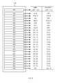
- Table 1provides signal descriptions for the ports shown in FIG. 2A .
- CE# Output Chip EnableThe Chip Enable signal selects the target NAND flash chip. When Chip Enable is high and the target is in the ready state, the target goes into a low-power standby state. When Chip Enable is low, the target is selected.
- CLE Output Command Latch EnableThe Command Latch Enable signal controls the target NAND flash chip to load a command from DQ[0:7] into its command register.
- ALE Output Address Latch EnableThe Address Latch Enable signal controls the target NAND flash chip to load an address from DQ[0:7] into its address register.
- WE# Output Write EnableThe Write Enable signal controls the latching of commands, addresses, and input data.
- RE Output Read Enable TrueThe Read Enable (True) signal enables data output on DQ[0:7].
- RE# Output Read Enable ComplementThe Read Enable Complement signal is the complementary signal to Read Enable True. Specifically, Read Enable Complement has the opposite value of Read Enable True when CE# is low, i.e., if RE is high then RE# is low; if RE is low then RE# is high.
- the DQ portis an 8-bit wide bidirectional port for transferring address, command, and data to and from the device.
- DQSis a data strobe signal providing synchronous reference for data input. The data strobe signal that indicates the data valid window.
- DQS# I/O DQ Data Strobe ComplementThe Data Strobe Complement signal is the complementary signal to Data Strobe True, optionally used in the NV-DDR2 data interface. Specifically, Data Strobe Complement has the opposite value of Data Strobe True when CE# is low, i.e. if DQS is high then DQS# is low; if DQS is low then DQS# is high.
- R/B# Input Ready/BusyThe Ready/Busy signal indicates the target status. When low, the signal indicates that one or more LUN operations are in progress. This signal is an open drain output and requires an external pull-up.
- FIG. 2Bshows the functional pinout of a memory controller 32 configured for another type of memory device operating in another protocol, which is one example of a selected memory interface protocol.
- a selected memory interface protocolis HLNANDTM memory interface protocol.
- Memory devicesmay operate in another type of memory interface protocol.
- FIG. 2Bthe ports for one channel are shown. Table 2 provides signal descriptions for the ports shown in FIG. 2A .
- CKI/CKI# Input ClockCKI and CKI# are the clock inputs from the (last) HLNAND TM device.
- CKI and CKI#are differential signals. All incoming command, address, read-out data from the (last) HLNAND device are referenced to the crossing edges of CKI and CKI# in both directions.
- CKO/ Output ClockCKO and CKO# are differential clock outputs. All outgoing command, address, and CKO# data are referenced to the crossing edges of CKO and CKO#.
- CE# Output Chip EnableWhen CE# is LOW, the device is enabled. Once device becomes “BUSY”, CE# pin should be LOW until the device becomes “READY”.
- CE# LOWactivates and CE# HIGH deactivates the internal clock signals.
- D[7:0] Input Data Input: D[7:0]receive read-out data from the (last) HLNAND device when DSI is HIGH and referenced to the crossing edges of CKI and CKI# in both directions.
- Q[7:0] Output Data Output: Q[7:0]transmit command and/or address packet along with CSO, and transmit write data along with DSO during write operation.
- CSO Output Command Strobe OutputWhen CSO is HIGH, command, address and/or write data through D[7:0] are latched on the crossing of CKI and CKI# by the device. When CSO is LOW, the device ignores input signals from D[7:0].
- CSOis used with command and address packets only.
- CSI Input Command Strobe InputEcho signal of CSO. May not be used by the controller in certain cases.
- DSI Input Data Strobe InputEcho signal of DSO.
- DSIis referenced to the crossing edges of CKO and CKO# and delineates the valid read-out data on D[7:0] pins from the Q[7:0] pins of the (last) HLNAND device.
- DSO Output Data Strobe OutputAfter READ-group commands, DSO enables the Q[7:0] buffer of the selected HLNAND device when HIGH. When DSO is LOW and CSO is LOW, the Q[7:0] buffer of the selected HLNAND device holds the previous states. After WRITE-group commands and DSO is HIGH, write data packets through Q[7:0] are transmitted to the (first) HLNAND device and shall be latched by the selected device on the crossing of CKI and CKI#.
- FIG. 3Aillustrates an example nonvolatile memory system using ONFi NAND flash devices.
- the memory systemincludes an ONFi configured memory controller 40 and several ONFi flash devices 42 , 44 and 46 . All input and output signals except chip select (CE#) signal in each flash memory device are connected to common bus or channel. Thus, the ONFi flash devices 42 , 44 and 46 are connected in parallel with the memory controller 40 , and is also referred to as a multi-drop configuration.
- the rest of the ONFi flash devicesare unselected by keeping CE#_2 and CE#_N High, such and they ignore any input like commands or addresses from the memory controller 40 . Also the output signals of the unselected ONFi flash devices are set to a high impedance (i.e. Hi-Z) state.
- Each of the ONFi flash devices 42 , 44 and 46use the same electrical signals for coordinating commands and data transfer between the ONFi flash device and a host controller device (not shown) through a channel control module.
- the ports for one channel control moduleare shown in FIG. 3A .
- Those signalsinclude data lines and control signals, such as ALE (Address Latch Enable), CLE (Command Latch Enable), WE# (Write Enable), RE#(Read Enable), and others as previously shown in Table 1.
- This type of interface protocolis known in the art as “ONFi NAND interface”.
- NAND interface protocolhas not, to date, been formally standardized by a standardization body, the manufacturers of NAND flash devices all follow the similar protocol for supporting the basic subset of NAND flash functionality. This is done so that customers using NAND flash memory devices within their electronic products could use NAND flash memory devices from any manufacturer without having to tailor their hardware or software for operating with the devices of a specific vendor. It is noted that some NAND flash memory vendors can provide extra functionality beyond this basic subset of functionality, while ensuring that the basic functionality is provided in order to provide compatibility with the protocol used by the other vendors.
- FIG. 3Billustrates an example of a non-volatile memory system using HLNAND flash memory devices.
- the memory systemincludes an HLNANDTM configured memory controller 60 and several HLNAND compatible flash devices 62 , 64 , 66 and 68 .
- the HLNAND memory devices 62 , 64 , 66 and 68uses a highly multiplexed unidirectional point-to-point bus architecture to transfer information such as commands, addresses and data. Each interconnection of these commands, addresses and data between memory devices is referred to as a “Link”.
- CKI/CKI#are input clocks.
- a Command/Address Packet on the D[0:7] ports delineated by CSIis latched on the rising edges of CKI or the falling edges of CKI#.
- a Write Data Packet on D[0:7] delineated by DSIis latched on the rising edges of CKI or the falling edges of CKI#.
- a Read Data Packet on Q[0:7] delineated by DSOis referenced at the rising edges of CKO or the falling edges of CKO#.
- CKO/CKO#are output clocks which are delayed version of CKI/CKI#.
- CSO, DSO and Q[0:7] signalsare referenced to the rising edges of CKO or to the falling edges of CKO#.
- Command/Address Packets through D[0:7]are latched on the rising edges of CKI or falling edges of CKI#.
- One clock cycle latencyis one of exemplary embodiment in this disclosure, however it could be any number of clock cycles depending on the design variations.
- tIOLclock cycle latency
- One clock cycle latencyis one of exemplary embodiment in this disclosure, however it could be any number of clock cycles depending on the design variations.
- the Data Input signal D[0:7]carries command, address and/or input data information
- the memory controller 60drives differential clocks from its ports CKO/CKO#, and all of the HLNAND compatible memory devices 62 , 64 , 66 and 68 receive the differential clock buses through their own clock ports, CKI/CKI#, from the previous CKO/CKO# ports in a series flow-through manner.
- the memory controller 60drives three different buses 70 , 72 and 74 through its ports, CSO, DSO and Q[0:7], respectively.
- the first memory device 62receives the three buses, 70 , 72 and 74 , through its ports, CSI, DSI and D[0:7], respectively.
- This pattern of receiving signals and re-driving them to successive memory devicescontinues until the last memory device 68 re-drives the final buses, 82 , 84 and 86 back to the memory controller 60 through the memory controller's input ports, CSI, DSI and D[0:7], respectively.
- it is not necessary to re-drive the signal from the CSO port of memory device 68therefore the CSI input port of memory controller 60 may be omitted, and final bus 84 is not required.
- ONFi and HLNAND memory interface protocolsdiffer sufficiently from each other, and any memory controller configured for the ONFi memory interface protocol will not work with HLNAND memory devices, and vice versa.
- the previously discussed ONFi and HLNAND memory systemsare merely examples of two different types of memory interface protocols that are not compatible with each other. Any of the previously mentioned memory device types are highly unlikely to be compatible with each other, as each type requires a specific memory interface protocol that would not work with a different memory device type.
- manufacturersmay design different data storage device devices based on different types of memory devices.
- traditional NAND flash memory device based data storage devicesare commonly available due to the availability and low cost of traditional NAND flash memory devices.
- thesecan be ONFi type flash memory devices.
- the multi-drop configuration of the ONFi type flash memory system as shown in FIG. 3Awill have a finite number of memory devices which can be connected in parallel to one channel of the memory controller 40 without degrading the overall speed and performance of the system. This is due to the cumulative loading effects of each memory device connected to the bus. Therefore, while the cost of such a data storage device may be low, the maximum storage density will also be relatively low.
- the HLNAND type of memory devicedoes not suffer from the limitations of multi-drop configured memory systems.
- the HLNAND memory systemsuch as the one shown in FIG. 3B by example, any number of memory devices can be connected in series with each other with one channel of the memory controller 60 . Therefore the total storage density of a data storage device using HLNAND type of memory devices can be very large.
- a memory controllerconfigurable to operate in at least one of two different memory interface protocols using one set of ports per channel.
- the ports of a channelare mapped to at least two different functional assignments, where each functional assignment corresponds to the signals specific to a memory interface protocol.
- Each portincludes a pad for electrical connection to a signal conductor line to a memory device, and buffer circuitry for each of the at least two functional assignments. Different buffer circuitry of each port is selectively enabled based on the selected memory interface protocol to be used.
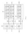
- FIG. 4A block diagram of a solid state storage device using a dual mode pinout memory controller according to an embodiment of the present disclosure is shown in FIG. 4 .
- the solid state storage device 100includes a dual mode pinout memory controller 102 and memory 104 .
- the memory 104includes non-volatile memory such as ONFi flash memory devices or HLNAND flash memory devices. In the present embodiment, any type of memory devices can be used as memory 104 . In the present context, memory 104 includes memory devices.
- the controller 102controls overall operations of the solid state storage device 100 , and controls exchange of data between the host and the memory 104 .
- the controller 102controls the memory 104 to write data or to read data, in response to a request from the host (not shown).
- the controller 102controls internal operations, such as for example, performance control, merging and wear leveling, which are needed for the characteristics of nonvolatile memory, or for efficient management of the memory 104 .
- the controller 102drives firmware and/or software for controlling operations of the memory 104 , which is referred to as a flash translation layer (FTL) (not shown).
- FTLflash translation layer
- the controller 102may control the memory 104 to control operation of a number of memories from among the multiple nonvolatile memories included in the memory device 104 , based on a request from the host.
- the memory 104provides storage medium for storing data. If memory 104 is at least a non-volatile memory device, the data is stored in a nonvolatile manner.
- the nonvolatile memory devicemay store an operating system (OS), various programs, and various multimedia data.
- OSoperating system
- various programsvarious multimedia data.
- the dual mode pinout memory controller 102controls exchange of data between the host and the memory 104 .
- the dual mode pinout memory controller 102includes a host interface block (HIB) 106 , a central processor unit 108 , a random access memory (RAM) 110 , a memory interface block (MIB) 112 , a read only memory (ROM) 114 , and an error correction code (ECC) engine 116 which are interconnected through a bus 118 .
- the controller 102may operate the FTL embodied as software or firmware.
- the RAM 110is shown integrated within the controller 102 , but it can be located outside of the controller 102 in alternate embodiments.
- the host interface block 106receives data, address information, external commands, and other signals from the host via host interface ports. These are generally referred to as information. The address information, commands and any other non-data related signals can be simply referred to as control information. Also, the host interface block 106 sends data, and status information to the host via the same or different host interface ports. These interface ports can include pins or other physical connectors. The received external commands from the host are used to control the memory controller 102 . Data and other information provided by the host to the solid state storage device 100 are input into functional blocks of the solid state storage device 100 , for example the buffer RAM 110 , through the host interface block 106 as an inlet for data. Also, data and other information provided from the solid state storage device 100 to the host are provided through the host interface block 106 as an outlet for data.
- the central processor 108reads a program code from the ROM 114 or the memory 104 , and controls all functional blocks included in the controller 102 according to the program code that is read.
- the program codespecifies operations of the central processor 108 .
- the central processor 108controls access to the memory 104 on a basis of the program code read. In one mode of operation, the program code stored in the memory 104 is read from the memory 104 and written to the RAM 110 at a time when the solid state storage device 100 is booted up.
- the RAM 110may be used as an operating memory of the processor 108 , and may be embodied as dynamic RAM (DRAM), static RAM (SRAM), or the like. Also, the RAM 110 may act as buffer memory for temporarily storing data received from the host.
- the processor 108performs overall control operations to write data to, or read data from, the memory 104 . Also, the processor 108 may control or otherwise perform operations of the FTL based on requests from the host.
- the ECC block 116generates an ECC (Error Correction Code) pertaining to data to be written to the memory 104 . Data are stored together with the ECC pertaining thereto. Furthermore the ECC block 116 detects and corrects bit errors in data read from the memory 104 on a basis of the ECC associated with the read data.
- ECCError Correction Code
- the ROM 114stores code data for interfacing with the host.
- firmware required for controlling the memory 104is stored.
- only minimum firmware required for bootingmay be stored in the ROM 114 and the other firmware may be stored in the memory 104 .
- the ROMis fixed read only memory, storing other firmware in the memory 102 facilitates updating of the firmware.
- the central processor 108 , RAM 110 , ROM 114 , ECC engine 116 and any other circuits required for processing information received from the host or the MIB 112can be referred to as core circuits.
- the memory interface block 112reads a sequence code from the ROM 114 or the memory 104 .
- the sequence codespecifies various operations performed by the memory interface block 112 .
- the memory interface block 112performs the various operations on a basis of the sequence code read.
- the sequence codeis composed of a plurality of code sets.
- the code setcomprises a plurality of codes. Each of the code sets specifies the operations corresponding thereto.
- data, address information, status information, internal commands and so onare transferred through an internal memory bus 120 .
- the internal memory bus 120includes signal conductor lines for electrically connecting ports of the controller 102 to corresponding ports of the memory 104 .
- the internal memory bus 120can carry signals corresponding to multiple channels.
- the internal commandis for the controller 102 to control the memory 104 , and the memory device 104 works according to the internal command. Incidentally, before the operations are performed, the sequence code stored in the memory 104 is read from the memory 104 and is written to the RAM 110 .
- the FTLincludes a mapping table (not shown) for performing data mapping operations.
- the mapping tableis stored in the RAM 110 .
- multiple logical page numbers (LPNs)are recorded to be respectively mapped to the memory 104 .
- LPNslogical page numbers
- datais written or read in units of a page.
- the LPNsmay therefore be used as mapping units.
- the FTLmay control the memory 104 based on whether a request from the host is a write command or a read command, and may manage the mapping table to be updated whenever the write command or the read command provided by the host is performed on the memory 104 . For example, when a request from the host is a write command, the FTL controls data to be written to one of the memory devices of memory 104 corresponding to an LPN, and writes the LPN and the corresponding memory device in the mapping table. When a request from the host is a read command, the FTL controls data to be read from one of the nonvolatile memories corresponding to an LPN, based on the mapping table.
- the memory 104may include multiple nonvolatile memories, each of which may be implemented as a NAND flash memory device that executes operations with a specific memory interface protocol.
- different types of memory devices having different memory interface protocolscan be used with the same dual pinout memory controller 102 .
- the memory interface block 112includes one set of ports for each channel, where at least one port is dynamically configurable to function in one of two modes, and each mode corresponds to a different memory interface protocol. Therefore two different types of memory 104 can be connected to a channel of the memory interface block 112 without the need for any additional ports, because both types of memory 104 can be connected to the same ports of the channel via the signal lines of bus 120 .
- the portscan be configured to function in either of the two memory interface protocols by connecting a dedicated or existing port to either the positive or ground power supplies (VDD or VSS). While such a technique is effective for selecting between one of two memory interface protocols, the memory interface block 112 can be configurable to have any number of memory interface protocols.
- a registercan be electrically programmed by blowing fuses or antifuses, or laser programmed, to provide a multi-bit code to select one of n modes of operation.
- more than two portscan be connected to VDD or VSS in order to provide a multi-bit code to select one of n modes of operation.
- the required buffer circuitry for each mode of operationis selectively couplable to a respective port of memory interface block 112 .
- the native memory controller signals received from the bus 118are converted by the selected buffer circuitry into a format compatible with the selected memory interface protocol.
- signals received from the bus 120are converted by the selected buffer circuitry into the native memory controller signals.
- FIG. 5shows a block diagram of a memory interface block 112 of the dual pinout memory controller 102 shown in FIG. 4 , where the memory interface block 112 is connected to at least one memory device.
- the memory interface block 112includes up to n channel control modules (CCM) 200 , where n can be any integer value greater than zero.
- CCMchannel control modules
- Each channel control module 200is associated with a channel, and is therefore connected to at least one memory device 202 via channel buses 204 . It is noted that the collection of channel busses 204 forms bus 120 shown in FIG. 4 . Similarly, all the memory devices 202 are included within memory 104 shown in FIG. 4 .
- the memory interface block 112further includes a mode selector 206 including a port which can be biased to VDD or VSS. In FIG.
- the option for connecting the mode selector port to VDD or VSSis shown by the inclusion of switch means 208 .
- the mode selector 206 and its corresponding portcan alternately be placed outside of memory interface block 112 , and within dual mode pinout memory controller 102 .
- the mode selector 206provides a mode selection signal to each of the channel control modules.
- each channel control module 200includes one set of ports, where at least one of the ports includes buffer circuitry that is configurable to function in at least one of two different modes, in response to the mode selection signal.
- the memory devices 202are ONFi type flash memory devices, then the interconnection configuration of the memory devices 202 and its channel control module would appear as shown in FIG. 3A .
- the memory devices 202are HLNAND type flash memory devices, then the interconnection configuration of the memory devices 202 and its channel control module would appear as shown in FIG. 3 B.
- both the ONFi type flash memory devices and the HLNAND type flash memory devicescan be connected to the channel control modules 200 .
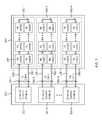
- FIG. 6is a block diagram of a multi-drop bus architecture memory system having a dual pinout memory controller, according to one embodiment. More specifically, FIG. 6 shows an example configuration of the solid state storage device 100 of FIG. 4 , configured in a multi-drop architecture.
- the memory interface block 220 of the dual pinout memory controllerincludes a plurality of channel control modules 222 - 1 to 222 -N each for controlling a respective channel 224 - 1 to 224 -N, also referred to as ONFi CH-1 to ONFi CH—N. It is noted that “N” is an integer number denoting the last unit of the element the base number refers to.
- the channelsare provided to a non-volatile memory 226 .
- each memory deviceIn electrical communication with each channel is a memory device 228 - 1 , 228 - 2 and 228 -N, where each memory device can be a single packaged memory device.
- Each of the memory devicesincludes a number of ONFi nonvolatile NAND flash memory chips 230 , of which only one is annotated in FIG. 6 .
- Each ONFi NAND flash memory chip 230is in bi-directional communication with its associated channel for receiving information from a channel control module, or for providing information to a channel control module.
- the memory chips 230 of a memory deviceare connected in parallel with a channel.
- Each of the channel control modules 222 - 1 to 222 -N of the memory interface block 220is dedicated to a respective channel ONFi CH-1 to ONFi CH—N of the nonvolatile memory 226 , for the purpose of controlling the nonvolatile memory 226 , and in particular, the individual memory devices 228 - 1 to 228 -N.
- the flash translation layerwhich is generally firmware and/or software, controls the operations of the channel control modules 222 - 1 to 222 -N corresponding to the channels ONFi CH-1 to ONFi CH—N in order to control the nonvolatile memory 226 to activate or deactivate various ONFi NAND flash memory chips 230 connected to channels ONFi CH-1 to ONFi CH—N, based on requests from a host.
- Activation of a memory chipcan include initiating various types of memory operations in the selected memory chip.
- HLNAND flash memoryis an advanced and high performance synchronous non-volatile flash memory device using point-to-point serial connection technology, typically arranged in a ring topology with a memory controller, as shown in FIG. 3B for example.
- FIG. 7is a block diagram of a serial point-to-point architecture memory system having the same dual pinout memory controller as the memory system of FIG. 6 , according to the present embodiment. More specifically, FIG. 7 shows an example configuration of the solid state storage device 100 of FIG. 4 , configured in a serial point-to-point architecture using HLNAND flash memory.
- the memory interface block 220has the same channel control modules 222 - 1 to 222 -N.
- non-volatile memory 250consists of HLNAND flash memory devices. As shown in FIG.
- non-volatile memory 250includes HLNAND flash memory devices 252 - 1 to 252 -N, each of which can include a packaged device consisting of a plurality of HLNAND memory chips 254 , of which only one is annotated. All the HLNAND memory chips 254 of a memory device, such as memory device 252 - 1 for example, are serially connected to each other via unidirectional, point-to-point connections. These point-to-point connections are formed in one example by having output pins of a device connected to input pins of the next device, and can take the form of a unidirectional bus. Accordingly, this serial interconnection can also be referred to as a daisy-chain cascade connection, or a ring topology configuration with a host, such as channel control module 222 - 1 .
- the channel control modules 222 - 1 to 222 -Nare each connected to respective HLNAND channels 256 - 1 to 256 -N, also referred to as HL CH-1 to HL CH—N.
- Each of the HLNAND channelsincludes an input sub-channel 258 - 1 and an output sub-channel 260 - 1 .
- the input sub-channel 258 - 1is the set of connections for providing data and control information to the first HLNAND memory chip 254 of the serially connected memory chips of memory device 252 - 1 , from output terminals of the channel control module 222 - 1 .
- the output sub-channel 260 - 1is the set of connections for providing data and control information from the last HLNAND memory chip 254 of the serially connected memory chips of memory device 252 - 1 , to input terminals of the channel control module 222 - 1 .
- the channel control modules 222 - 1 to 222 -N in this systemneed only to interface with the first HLNAND memory chip and the last HLNAND memory chip of the memory device.
- no bus termination that is typically used in multi-drop bus architecturesis required. As a result, lower power consumption compared to a flash memory system using a multi-drop bus architecture is realized.
- the FTLmay control the operations of the channel control modules 222 - 1 to 222 -N in order to control the non-volatile memory 250 to activate or deactivate various HLNAND flash memory chips 254 corresponding to the channels HL CH-1 to HL CH—N, based on requests from a host device, such as host 14 of FIG. 1 .
- Activation of a memory chipcan include initiating various types of memory operations in the selected memory chip.
- FIGS. 6 and 7illustrate memory systems using the same dual pinout memory controller according to the present disclosure.
- the ONFi and HLNAND memory types used for non-volatile memory 226 and 250are merely examples of two different types of memories the dual pinout memory controller of the present disclosure can be used with.
- Different embodiments of the dual pinout memory controllercan be configured to interface with combinations of presently known memories and future memories which have differing input/output interfaces.
- FIG. 8is a block diagram of one of the channel control modules 200 shown in FIG. 5 .
- the channel control module 200is configurable to operate with one of two memory interface protocols.
- the two memory interface protocols being usedare the ONFi and HLNAND memory interface protocols.
- the channel control module 200includes an ECC encoder 300 , an ECC decoder 302 , a command processor 304 , an address processor 306 , channel control logic 308 , a data scrambler 310 , a data descrambler 312 , an encryption processor 314 , an EDC processor 316 , and a dual memory interface module 318 .
- the dual memory interface module 318includes a set of ports for electrical coupling to a memory device (not shown). The function of some of the above mentioned components is described with further reference to the block diagram of FIG. 4 .
- the data that is programmed into the memory device through the channel control module 200has an error detection or error correction code appended to it and stored with the main data in the memory cell array of the memory device.
- the channel control module 200uses the ECC encoder 300 for this function.
- the ECC decoder 302re-generates the ECC code from the data and compares it to the ECC code that was appended to the data when programmed into the memory device. If the data is identical to the data that was written, the ECC circuits indicate that there is no data error present. If some difference in the read data is detected, and the difference is small enough to be within the capability of the ECC to correct, the read data (typically contained in the RAM 110 ) is “corrected” or modified to restore it to the original value by the ECC correction engine 116 , as controlled by the processor 108 . If the data errors exceed the ECC correction capability, an “uncorrectable” read error occurs. Typically, an uncorrectable read error would result in an error status being returned to the host interface when read.
- the processor 108also translates the address from the host interface block 106 into an internal NAND address and stores it in the channel control module's address processor 306 . If logical-to-physical address conversion is to be performed, the processor 108 can use a mapping table to create the correct physical address. The processor 108 can also perform one or more additional functions described below. The processor 108 then sets up a data transfer from the RAM 110 to the channel control module 200 . It is noted that the memory interface block 112 can include multiple channel control modules, as shown in FIG. 5 .
- the channel control module 200takes the value from the address processor 306 and formats it in accordance with the ONFi memory interface protocol format or HLNAND memory interface protocol format.
- the data stored in the RAM 110is sent to the encryption processor 314 for encryption and is then sent through the data scrambler 310 .
- the data scrambler 310scrambles the data and outputs the scrambled data to the ECC encoder 300 , which generates the ECC parity bits to be stored with the data.
- the data and ECC parity bitsare then transferred, through the dual memory interface module 318 ports, with either an ONFi memory interface protocol format or an HLNAND memory interface protocol format, with the page program or write command to the memory devices for storage.
- the channel control module 200further includes an EDC processor 316 that includes an EDC encoder and an EDC decoder.
- the EDC processor 316executes an Error Detection Coding algorithm for either the HLNAND or ONFi memory interface protocols.
- the channel control logic 308is generally responsible for routing the processed information and data from one functional block to another, and the dual memory interface module 318 and the bus.
- channel control module 200execute data processing operations on the data to be written to the memory devices, and on the data read from the memory devices independent of the memory interface protocol being used. It is noted that the channel control logic 308 can also determine when to drive control signals through the dual memory interface module 318 , such as control signals CLE, ALE, CSO and DSO for example, so that their assertions would be coordinated with specific memory operations and with the proper sequence. Accordingly, the channel control logic 308 is configured to execute algorithms specific to both HLNAND and ONFi.
- the dual memory interface module 318is responsible for capturing the data and other information received at the single set of ports, and converting the data and the received information from either of the two memory interface protocol formats into a native memory controller format. Conversely, the dual memory interface module 318 is responsible for providing commands, address and write data in either of the two memory interface protocol formats. As only a single set of ports are available, at least one port is assigned two different functions. It is possible that between two different memory interface protocols, only one signal differs in function. On the other hand, it is possible that every signal between two different memory interface protocols differs in function.
- FIG. 9is a block diagram of the dual memory interface module 318 of FIG. 8 , with multiple functional assignments for each port.
- specific categories of signals in both memory interface protocolsare mapped to the same port, wherever possible.
- Categories of signalsinclude output signals, input signals, and bidirectional signals.
- Types of signalsinclude control, status, data, and clock signals.
- Each category of signalshas a corresponding type of buffer circuit connected to a pad.
- the dual memory interface module 318has port buffer circuits configured for two different memory interface protocols, such as the ONFi and HLNAND memory interface protocols.
- the dual memory interface module 318 embodiment of FIG. 9includes a port buffer circuit for each pad, where a pad is a metallized area of the semiconductor substrate for electrical connection to one end of a bond wire. The other end of the bond wire is connected to a physical pin of the package which encapsulates the semiconductor substrate.
- the dual memory interface module 318 embodimentincludes multiple port buffer circuits indicated by reference numbers 400 , 402 , 404 and 406 .
- the port buffer circuit 400is an input buffer circuit, which in the present embodiment is a mode selector circuit. As shown in the table of FIG.
- connection of the pad of port buffer circuit 400 to VDD (logic 1) or VSS (logic 0)selects which of the two memory interface protocols the other port buffer circuits 402 , 404 and 406 are to be configured as.
- the port buffer circuits 402 and 406are bi-directional port buffer circuits, meaning that they include driver and receiver circuits for outputting a signal and receiving a signal, respectively.
- the port buffer circuits 402 and 406are configured differently from each other due to the types of signals they each receive.
- the port buffer circuits 404are unidirectional port buffer circuits, and in particular, include only driver circuits for outputting a signal.
- dual memory interface module 318On the right side of dual memory interface module 318 is a table listing the signal assignments for each port buffer circuit.
- the left-most columnlists the ONFi memory interface protocol signals for each port buffer circuit while the right-most column lists the HLNAND memory interface protocol signals for the same port buffer circuits.
- the present exampleillustrates one possible dual pinout mapping for the port buffer circuits. As shown in the table of FIG. 9 , clock signals such as CKI and DQS from the two memory interface protocols are mapped to the same port buffer circuit 402 , control signals such as CLE and CSO are mapped to the same port buffer circuit 404 .
- the ONFi memory interface protocoluses 8 bi-directional port buffer circuits for providing and receiving data signals DQ[0] to DQ[7], while the HLNAND memory interface protocol requires 8 ports for receiving input data D[0] to D[7] and 8 ports for driving output data Q[0] to Q[7]. Therefore, there is no direct mapping of the 16 data signals of the HLNAND memory interface protocol to the 8 data signals of the ONFi memory interface protocol.
- the ONFi memory interface protocolrequires individual chip enable signals CE[0] to CE[7] for enabling respective ONFi memory devices of the channel, which are not required in the HLNAND memory interface protocol. Therefore, the chip enable ports for the ONFi memory interface protocol are configured to output data in the HLNAND memory interface protocol.
- the dual memory interface module 318 of FIG. 9is intended to illustrate examples of how multiple signals can be assigned to the same port, and therefore may not show all the ports and signals for the ONFi and HLNAND memory interface protocols.
- Embodiments of the port buffer circuits 400 , 402 , 404 and 406are shown in the circuit schematics of FIGS. 10, 11, 12 and 13 .
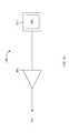
- FIG. 10is a circuit schematic of the mode selection circuit 400 shown in FIG. 9 , according to an embodiment of the present disclosure.
- the other port buffer circuitsare configured to operate in one of two different modes, depending on how the mode selection circuit 400 is set.
- a pad 500is a metallized area on the surface of a semiconductor chip or substrate, to which connections such as gold wire bonding can be made.
- pad 500is wire bonded to one of the power supply VDD or ground VSS.
- Input receiver circuitry 502such as an input buffer circuit by example, detects the VDD or VSS connection of pad 500 to drive an internal a select signal SEL to either the internal high or low logic levels.
- SELis a logic low level (0)
- the dual mode pinout memory controller 102is set to operate with a first memory interface protocol, such as the ONFi memory interface protocol.
- the dual mode pinout memory controller 102When SEL is at a logic high level (1), the dual mode pinout memory controller 102 is set to operate with a second memory interface protocol, such as the HLNAND memory interface protocol. More specifically, each of the other port buffer circuits of the dual mode pinout memory controller is configured to receive or provide one of the two signals mapped to it.
- two or more padscan be used for selecting between more than 2 different memory interface protocol modes, where each pad is connected to a respective input buffer circuit and the outputs can be decoded to enable specific logic circuitry of each port buffer circuit.
- FIG. 11is a circuit schematic of the bi-directional port buffer circuit 402 shown in FIG. 9 , according to an embodiment of the present disclosure.
- a pad 510can be electrically coupled to either the DQS pin of an ONFi memory device or the CKI pin of an HLNAND compliant memory device.
- the buffer circuitryincludes a receive path and an output path.
- the receive pathincludes a receiver 512 , such as an input buffer, a selector such as demultiplexor 514 , and a first logic block 516 configured for receiving a signal from one memory interface protocol, such as the HLNAND memory interface protocol.
- the first logic block 516is specifically configured to receive the CKI signal from pad 510 via demultiplexor 514 , and may be configured to process the signal according to the requirements of the HLNAND memory interface protocol, and provides any required signals to specific circuit blocks of the channel control module 200 .
- the HLNAND logic block 516provides a buffered clock signal to the channel control module, and may include a delay locked loop (DLL) or a phase locked loop (PLL).
- DLLdelay locked loop
- PLLphase locked loop
- the signal received by demultiplexor 514is referred to as “in”, which can correspond to the received DQS or CKI signals at pad 510 .
- the demultiplexor 514is controlled by selection signal SEL to pass signal “in” to one of two outputs labeled “0” and “1”.
- “in”is passed to the “1” output when SEL is at a logic level corresponding to selecting the HLNAND memory interface protocol mode. Conversely, “in” is passed to the “0” output when SEL is at a logic level corresponding to the ONFi memory interface protocol mode.
- SELis at the low logic level for the ONFi memory interface memory protocol mode, and at the high logic level for the HLNAND memory interface protocol mode.
- demultiplexor 514provides clock signal CLK_in to logic block 516
- demultiplexor 514provides data clock signal DQS_in to a second logic block 518 .
- the output pathincludes the second logic block 518 , which controls both the output data clock signal DQS_out and the received input data clock signal DQS_in.
- second logic block 518receives DQS_in from the dual memory interface module 318 and processes the signal to provide input data synchronization, in accordance with the requirements of the ONFi memory interface protocol, and provides any required signals to specific circuit blocks of the channel control module 200 .
- the second logic block 518receives signals from the other circuits of the channel control module 200 , such as the dual memory interface module 318 , to generate the output data clock signal DQS_out for output data synchronization.
- the DQS_out signalis driven by output driver 520 , to pad 510 .
- output driver 520is enabled or disabled by selection signal SEL.
- selection signal SELAs previously discussed for demultiplexor 514 , SEL at a low logic level corresponds to the ONFi memory interface protocol mode. Therefore in this mode of operation, output driver 520 is enabled, or turned on for amplifying the DQS_out signal and driving pad 510 .
- output driver 520In the other mode of operation, namely when SEL is at a high logic level corresponding to the HLNAND memory interface protocol mode, output driver 520 is disabled, or turned off, leaving receiver 512 turned on to provide the received CKI signal from pad 510 to logic block 516 via demultiplexor 514 . Then the buffered clock signal is provided to the dual memory interface module 318 .
- both the output driver 520 and the receiver 512are enabled so that any output DQS signal can be driven onto pad 510 while any received input DQS signal can be received by logic block 518 through receiver 512 and demultiplexor 514 .
- the port buffer circuit 402is configured for either bi-directional DQS signals or a received CKI signal.
- a similar port buffer circuitcan be employed for the other port buffer circuits labeled 402 in FIG. 9 .
- each ONFi signalis a bi-directional signal
- the HLNAND signal mapped to each bi-directional ONFi signalis an input signal.
- the logic blocks 516 and 518 shown in FIG. 11would be configured for processing those specific signals mapped to them.
- FIG. 12is a circuit schematic of the output port buffer circuit 404 shown in FIG. 9 , according to an embodiment of the present disclosure.
- the output port buffer circuit 404includes a first logic block 530 configured to process a signal corresponding to a first memory interface protocol, a second logic block 532 configured to process a signal corresponding to a second memory interface protocol, a selector such as a multiplexor 534 , an output driver 536 , and a pad 538 .
- the first logic block 530is an ONFi logic block and the second logic block 532 is an HLNAND logic block.
- the ONFi logic block 530receives information from the dual interface memory module 318 for providing a read enable signal RE_out in response to other circuit blocks of the channel control module 200 , which is received by the “0” input of multiplexor 534 . More specifically, the ONFi logic block 530 is configured to process received signals according to requirements of the protocol, to generate the RE_out signal.
- the HLNAND logic block 532provides an output clock signal CKO_out in response to information received from the dual interface memory module 318 , which is received by the “1” input of multiplexor 534 . More specifically, the HLNAND logic block 532 is configured to process received signals according to requirements of the protocol, to generate the CKO_out signal.
- the multiplexor 534passes one of the RE_out and CKO_out as signal “out” in response to selection signal SEL.
- SEL at the high logic levelcorresponds to the HLNAND memory interface protocol mode, thereby passing CKO_out to output driver 536 .
- SEL at the low logic levelcorresponds to the ONFi memory interface protocol mode, thereby passing RE_out to output driver 536 .
- the output driver 536then amplifies and drives its received signal onto pad 538 . It is noted that both signals RE and CKO are output signals for the ONFI and HLNAND memory interface protocols. Therefore the embodiment of FIG. 12 is an example showing how a port buffer circuit is configured to provide two different output signals.
- FIG. 13is a circuit schematic of the alternate bi-directional port buffer circuit 406 shown in FIG. 9 , according to an embodiment of the present disclosure.
- the bi-directional port buffer circuit 406includes a receive path and an output path.
- the output pathincludes a first logic block 550 , and an output driver 552 for amplifying and driving a signal onto pad 554 .
- the receive pathincludes a receiver 556 for pre-conditioning the signal received at pad 554 , and a second logic block 558 .
- the first logic blockis an ONFi logic block that provides a write enable signal WE_out in response to other circuit blocks of the channel control module 200
- the second logic blockis an HLNAND logic block that receives a data strobe input signal DSI_in that is provided to other circuit blocks of the channel control module 200
- the logic block 550is configured to process the signals received from the other circuit blocks of channel control module 200 according to requirements of the selected protocol, for generating the WE_out signal.
- the logic block 558is configured to process the DSI_in signal according to requirements of the selected protocol, and provide any required signals to specific circuit blocks of the channel control module 200 .
- the presently shown bi-directional port buffer circuitillustrates an example configuration where the pad provides an output signal in a first memory interface protocol mode, and receives an input signal in a second memory interface protocol mode. For example, when selection signal SEL is at the low logic level, output driver 552 is enabled while receiver 556 is disabled. Conversely, when SEL is at the high logic level, output driver 552 is disabled while receiver 556 is enabled. Accordingly, only one of the receive path and output path is active depending on the state of selection signal SEL.
- FIG. 13shows output driver 520 and input buffer 512 being enabled or disabled by the selection signal SEL. While the embodiment of FIG. 11 shows just the output driver 520 being enabled or disabled by SEL, in an alternate embodiment, input buffer 512 can be enabled or disabled by SEL.
- FIG. 14is a circuit schematic of a dual mode input interface circuit, according to an embodiment of the present disclosure. This particular circuit embodiment can be used when input signals for two different memory interface protocols are mapped to the same port.
- dual input port buffer circuit 570includes a pad 572 , a receiver 574 connected to pad 572 , a selector such as a demultiplexor 576 , a first logic block 578 configured to process a signal corresponding to a first memory interface protocol, and a second logic block 580 configured to process a signal corresponding to a second memory interface protocol. In the presently shown embodiment, no signals specific to any memory interface protocol are shown.
- the pad 572can be electrically coupled to receive a first input or a second input, each corresponding to a different memory interface protocol.
- the receiver 574buffers the signal received at pad 572 , and passes the signal as “in” to an input of demultiplexor 576 .
- Demultiplexor 576passes “in” to either its “0” or “1” outputs in response to a state of the selection signal SEL.
- SELis set to either the high or low logic levels to indicate the selected memory interface protocol being used.
- the logic blocks 578 and 580are configured to process the signals according to requirements of the selected protocol, and provide any required signals to specific circuit blocks of the channel control module 200 .
- the previously shown embodiment of FIG. 9 , and the port buffer circuit embodiments of FIGS. 10 to 14show examples of one possible dual pinout mapping arrangement for the dual mode pinout memory controller embodiment. Other dual pinout mappings are possible, provided the port the signals are mapped to is configured to receive or provide the mapped signals.
- the previously shown port buffer circuit embodimentscan be used for mapping combinations of input, output and bi-directional signals to a single port.
- the signals received at the port buffer circuitsare received and processed by the channel control module 200 , and passed to other circuit blocks of the memory controller 102 via bus 118 .
- datais provided to the host via host interface 106 .
- any data and commands received at host interface 106are processed by the circuit blocks of the memory controller via bus 118 , and ultimately provided to a targeted channel control module of memory interface 112 , which executes the necessary protocol adaptations for signaling to the memory devices.
- each port buffer circuitcan be configured to receive more than 2 different types of signals.
- the shown 2-1 multiplexors or 1-2 demultiplexorscan be replaced with 3-1 multiplexors or 1-3 demultiplexors, and an additional logic block can be included for processing signals for outputting the third signal, or for processing the received third signal.
- an additional logic blockcan be included for processing signals for outputting the third signal, or for processing the received third signal.
- the dual mode pinout memory controller embodimentscan be used in any memory system, such as solid state memory systems including SSD drives and other portable memory storage devices.
- the dual mode pinout memory controller embodimentscan further be integrated with systems that use non-volatile memory, such as in portable electronic devices including mobile phones, laptop computers and tablets by example.
- the device elements and circuitsare connected to each other as shown in the figures, for the sake of simplicity.
- elements, circuits, etc.may be connected directly to each other.
- elements, circuits etc.may be connected indirectly to each other through other elements, circuits, etc., necessary for operation of devices and apparatus.
- the circuit elements and circuitsare directly or indirectly coupled with or connected to each other.
Landscapes
- Engineering & Computer Science (AREA)
- Theoretical Computer Science (AREA)
- Physics & Mathematics (AREA)
- General Engineering & Computer Science (AREA)
- General Physics & Mathematics (AREA)
- Read Only Memory (AREA)
Abstract
Description
| TABLE 1 | ||
| Pin Name | Type | Description |
| CE# | Output | Chip Enable: The Chip Enable signal selects the target NAND flash chip. |
| When Chip Enable is high and the target is in the ready state, the target goes | ||
| into a low-power standby state. When Chip Enable is low, the target is selected. | ||
| CLE | Output | Command Latch Enable: The Command Latch Enable signal controls the |
| target NAND flash chip to load a command from DQ[0:7] into its command | ||
| register. | ||
| ALE | Output | Address Latch Enable: The Address Latch Enable signal controls the target |
| NAND flash chip to load an address from DQ[0:7] into its address register. | ||
| WE# | Output | Write Enable |
| The Write Enable signal controls the latching of commands, addresses, and | ||
| input data. Data, commands, and addresses are latched on the rising edge of | ||
| WE#. | ||
| RE | Output | Read Enable True |
| The Read Enable (True) signal enables data output on DQ[0:7]. | ||
| RE# | Output | Read Enable Complement |
| The Read Enable Complement signal is the complementary signal to Read | ||
| Enable True. Specifically, Read Enable Complement has the opposite value of | ||
| Read Enable True when CE# is low, i.e., if RE is high then RE# is low; if RE is | ||
| low then RE# is high. | ||
| DQ[0:7] | I/O | Data Input/Output: DQ[0:7] The DQ port is an 8-bit wide bidirectional port for |
| transferring address, command, and data to and from the device. | ||
| DQS | I/O | DQ Data Strobe True: DQS is a data strobe signal providing synchronous |
| reference for data input. The data strobe signal that indicates the data valid | ||
| window. | ||
| DQS# | I/O | DQ Data Strobe Complement |
| The Data Strobe Complement signal is the complementary signal to Data | ||
| Strobe True, optionally used in the NV-DDR2 data interface. Specifically, Data | ||
| Strobe Complement has the opposite value of Data Strobe True when CE# is | ||
| low, i.e. if DQS is high then DQS# is low; if DQS is low then DQS# is high. | ||
| WP# | Output | Write Protect: Protects against inadvertent PROGRAM and ERASE |
| operations. All PROGRAM and ERASE operations are disabled when WP# is | ||
| LOW. | ||
| R/B# | Input | Ready/Busy: The Ready/Busy signal indicates the target status. When low, |
| the signal indicates that one or more LUN operations are in progress. This | ||
| signal is an open drain output and requires an external pull-up. | ||
| TABLE 2 | ||
| Pin Name | Type | Description |
| CKI/CKI# | Input | Clock: CKI and CKI# are the clock inputs from the (last) HLNAND ™ device. CKI and |
| CKI# are differential signals. All incoming command, address, read-out data from the (last) | ||
| HLNAND device are referenced to the crossing edges of CKI and CKI# in both directions. | ||
| CKO/ | Output | Clock: CKO and CKO# are differential clock outputs. All outgoing command, address, and |
| CKO# | data are referenced to the crossing edges of CKO and CKO#. | |
| CE# | Output | Chip Enable: When CE# is LOW, the device is enabled. Once device becomes “BUSY”, |
| CE# pin should be LOW until the device becomes “READY”. In addition, CE# LOW | ||
| activates and CE# HIGH deactivates the internal clock signals. | ||
| D[7:0] | Input | Data Input: D[7:0] receive read-out data from the (last) HLNAND device when DSI is HIGH |
| and referenced to the crossing edges of CKI and CKI# in both directions. | ||
| Q[7:0] | Output | Data Output: Q[7:0] transmit command and/or address packet along with CSO, and |
| transmit write data along with DSO during write operation. | ||
| CSO | Output | Command Strobe Output: When CSO is HIGH, command, address and/or write data |
| through D[7:0] are latched on the crossing of CKI and CKI# by the device. When CSO is | ||
| LOW, the device ignores input signals from D[7:0]. CSO is used with command and | ||
| address packets only. | ||
| CSI | Input | Command Strobe Input: Echo signal of CSO. May not be used by the controller in |
| certain cases. | ||
| DSI | Input | Data Strobe Input: Echo signal of DSO. DSI is referenced to the crossing edges of CKO |
| and CKO# and delineates the valid read-out data on D[7:0] pins from the Q[7:0] pins of the | ||
| (last) HLNAND device. | ||
| DSO | Output | Data Strobe Output: After READ-group commands, DSO enables the Q[7:0] buffer of the |
| selected HLNAND device when HIGH. When DSO is LOW and CSO is LOW, the Q[7:0] | ||
| buffer of the selected HLNAND device holds the previous states. After WRITE-group | ||
| commands and DSO is HIGH, write data packets through Q[7:0] are transmitted to the | ||
| (first) HLNAND device and shall be latched by the selected device on the crossing of CKI | ||
| and CKI#. | ||
Claims (15)
Priority Applications (6)
| Application Number | Priority Date | Filing Date | Title |
|---|---|---|---|
| US13/835,968US9471484B2 (en) | 2012-09-19 | 2013-03-15 | Flash memory controller having dual mode pin-out |
| KR1020147036998AKR102113359B1 (en) | 2012-09-19 | 2013-09-18 | Flash memory controller having dual mode pin-out |
| PCT/CA2013/000782WO2014043788A1 (en) | 2012-09-19 | 2013-09-18 | Flash memory controller having dual mode pin-out |
| CN201380048582.4ACN104704563B (en) | 2012-09-19 | 2013-09-18 | Flash memory controller with double mode pin |
| JP2015531407AJP6386460B2 (en) | 2012-09-19 | 2013-09-18 | Flash memory controller with dual mode pinout |
| TW102133883ATWI595488B (en) | 2012-09-19 | 2013-09-18 | Flash memory controller having dual mode pin-out |
Applications Claiming Priority (3)
| Application Number | Priority Date | Filing Date | Title |
|---|---|---|---|
| US201261702846P | 2012-09-19 | 2012-09-19 | |
| US201261713008P | 2012-10-12 | 2012-10-12 | |
| US13/835,968US9471484B2 (en) | 2012-09-19 | 2013-03-15 | Flash memory controller having dual mode pin-out |
Publications (2)
| Publication Number | Publication Date |
|---|---|
| US20140082260A1 US20140082260A1 (en) | 2014-03-20 |
| US9471484B2true US9471484B2 (en) | 2016-10-18 |
Family
ID=50275695
Family Applications (1)
| Application Number | Title | Priority Date | Filing Date |
|---|---|---|---|
| US13/835,968Expired - Fee RelatedUS9471484B2 (en) | 2012-09-19 | 2013-03-15 | Flash memory controller having dual mode pin-out |
Country Status (6)
| Country | Link |
|---|---|
| US (1) | US9471484B2 (en) |
| JP (1) | JP6386460B2 (en) |
| KR (1) | KR102113359B1 (en) |
| CN (1) | CN104704563B (en) |
| TW (1) | TWI595488B (en) |
| WO (1) | WO2014043788A1 (en) |
Cited By (10)
| Publication number | Priority date | Publication date | Assignee | Title |
|---|---|---|---|---|
| US10403341B2 (en) | 2017-09-13 | 2019-09-03 | Toshiba Memory Corporation | Semiconductor integrated circuit and semiconductor device |
| US10452588B2 (en) | 2016-08-23 | 2019-10-22 | Toshiba Memory Corporation | Semiconductor device |
| US10691838B2 (en)* | 2014-06-20 | 2020-06-23 | Cypress Semiconductor Corporation | Encryption for XIP and MMIO external memories |
| US10706898B2 (en) | 2018-07-27 | 2020-07-07 | SK Hynix Inc. | Semiconductor apparatus and data processing system |
| US11301400B2 (en)* | 2020-03-23 | 2022-04-12 | Kioxia Corporation | Semiconductor storage device and control method thereof for various interface standards |
| US20220358060A1 (en)* | 2016-03-03 | 2022-11-10 | Samsung Electronics Co., Ltd. | Asynchronous communication protocol compatible with synchronous ddr protocol |
| US20230305592A1 (en)* | 2022-02-25 | 2023-09-28 | SK Hynix Inc. | Memory system related to clock synchronization |
| US11775462B2 (en) | 2018-03-09 | 2023-10-03 | Samsung Electronics Co., Ltd. | Adaptive interface storage device with multiple storage protocols including NVMe and NVMe over fabrics storage devices |
| US11942180B2 (en) | 2021-09-01 | 2024-03-26 | Kioxia Corporation | Memory system |
| TWI892481B (en) | 2023-10-11 | 2025-08-01 | 南亞科技股份有限公司 | Memory system and receiver |
Families Citing this family (52)
| Publication number | Priority date | Publication date | Assignee | Title |
|---|---|---|---|---|
| US8560604B2 (en) | 2009-10-08 | 2013-10-15 | Hola Networks Ltd. | System and method for providing faster and more efficient data communication |
| IL210169A0 (en) | 2010-12-22 | 2011-03-31 | Yehuda Binder | System and method for routing-based internet security |
| EP3364304B1 (en)* | 2011-09-30 | 2022-06-15 | INTEL Corporation | Memory channel that supports near memory and far memory access |
| US9324389B2 (en)* | 2013-05-29 | 2016-04-26 | Sandisk Technologies Inc. | High performance system topology for NAND memory systems |
| US9728526B2 (en) | 2013-05-29 | 2017-08-08 | Sandisk Technologies Llc | Packaging of high performance system topology for NAND memory systems |
| US9241044B2 (en) | 2013-08-28 | 2016-01-19 | Hola Networks, Ltd. | System and method for improving internet communication by using intermediate nodes |
| US20150161038A1 (en)* | 2013-12-10 | 2015-06-11 | Conversant Intellectual Property Management Inc. | System and Method of Operation for High Capacity Solid-State Drive |
| US20150261446A1 (en)* | 2014-03-12 | 2015-09-17 | Futurewei Technologies, Inc. | Ddr4-onfi ssd 1-to-n bus adaptation and expansion controller |
| US11023846B2 (en) | 2015-04-24 | 2021-06-01 | United Parcel Service Of America, Inc. | Location-based pick up and delivery services |
| US10121013B2 (en) | 2015-05-07 | 2018-11-06 | Samsung Electronics Co., Ltd. | XOR-based scrambler/descrambler for SSD communication protocols |
| US11057446B2 (en) | 2015-05-14 | 2021-07-06 | Bright Data Ltd. | System and method for streaming content from multiple servers |
| KR102417182B1 (en)* | 2015-06-22 | 2022-07-05 | 삼성전자주식회사 | Data storage device and data processing system having the same |
| US10423545B2 (en)* | 2015-07-08 | 2019-09-24 | International Business Machines Corporation | Adjusting an optimization parameter to customize a signal eye for a target chip on a shared bus |
| US10114788B2 (en) | 2015-07-08 | 2018-10-30 | International Business Machines Corporation | Adjusting an optimization parameter to customize a signal eye for a target chip on a shared bus |
| US10241937B2 (en) | 2015-07-08 | 2019-03-26 | International Business Machines Corporation | Adjusting an optimization parameter to customize a signal eye for a target chip on a shared bus |
| KR20170046862A (en)* | 2015-10-21 | 2017-05-04 | 에스케이하이닉스 주식회사 | Memory system and operating method of memory system |
| US10310547B2 (en)* | 2016-03-05 | 2019-06-04 | Intel Corporation | Techniques to mirror a command/address or interpret command/address logic at a memory device |
| CN105788636A (en)* | 2016-04-05 | 2016-07-20 | 山东华芯半导体有限公司 | EMMC controller based on parallel multichannel structure |
| US10824348B2 (en)* | 2016-08-02 | 2020-11-03 | Samsung Electronics Co., Ltd. | Method of executing conditional data scrubbing inside a smart storage device |
| KR102669694B1 (en)* | 2016-09-28 | 2024-05-28 | 삼성전자주식회사 | Electronic device configured to reset a storage device which non-directly connected to application processor from among serially connected storage devices and operating method thereof |
| JP2018073438A (en)* | 2016-10-24 | 2018-05-10 | 東芝メモリ株式会社 | Semiconductor memory device |
| KR102725115B1 (en)* | 2017-02-17 | 2024-11-05 | 삼성전자주식회사 | Storage device and operating method of storage device |
| TWI690806B (en)* | 2017-05-22 | 2020-04-11 | 義隆電子股份有限公司 | Data transmitting device and data receiving device for a serial peripheral interface |
| CN107479938B (en)* | 2017-09-27 | 2024-03-29 | 北京忆芯科技有限公司 | Electronic devices and methods of starting them |
| KR102535243B1 (en)* | 2017-12-18 | 2023-05-23 | 에스케이하이닉스 주식회사 | Memory system and operating method thereof |
| KR20190118428A (en)* | 2018-04-10 | 2019-10-18 | 에스케이하이닉스 주식회사 | Controller and memory system having the same |
| US10877678B2 (en) | 2018-05-17 | 2020-12-29 | Micron Technology, Inc. | Selection component that is configured based on an architecture associated with memory devices |
| WO2020076718A1 (en)* | 2018-10-12 | 2020-04-16 | Rambus Inc. | Command buffer chip with dual configurations |
| US10901734B2 (en)* | 2019-03-01 | 2021-01-26 | Micron Technology, Inc. | Memory mapping using commands to transfer data and/or perform logic operations |
| US10978117B2 (en) | 2019-03-26 | 2021-04-13 | Micron Technology, Inc. | Centralized placement of command and address swapping in memory devices |
| US10811057B1 (en) | 2019-03-26 | 2020-10-20 | Micron Technology, Inc. | Centralized placement of command and address in memory devices |
| US10811059B1 (en) | 2019-03-27 | 2020-10-20 | Micron Technology, Inc. | Routing for power signals including a redistribution layer |
| US11031335B2 (en) | 2019-04-03 | 2021-06-08 | Micron Technology, Inc. | Semiconductor devices including redistribution layers |
| CN112069085B (en)* | 2019-06-10 | 2023-06-02 | 苏州库瀚信息科技有限公司 | System and method for dual-mode flash memory controller and dual-mode memory communication |
| US11416422B2 (en)* | 2019-09-17 | 2022-08-16 | Micron Technology, Inc. | Memory chip having an integrated data mover |
| US11417372B2 (en)* | 2020-03-06 | 2022-08-16 | Micron Technology, Inc. | Interface protocol configuration for memory |
| US11210429B2 (en)* | 2020-03-10 | 2021-12-28 | Micron Technology, Inc. | Memory access gate |
| CN111383154A (en)* | 2020-04-02 | 2020-07-07 | 广东金宇恒软件科技有限公司 | Data interface and public financial budget management integrated platform system convenient to manage |
| US11182312B2 (en)* | 2020-04-02 | 2021-11-23 | Micron Technology, Inc. | Memory sub-system manufacturing mode |
| CN111883037A (en)* | 2020-07-28 | 2020-11-03 | 重庆惠科金渝光电科技有限公司 | Time sequence control plate, driving device and display device |
| CN111833797A (en)* | 2020-07-28 | 2020-10-27 | 重庆惠科金渝光电科技有限公司 | Time sequence control plate, driving device and display device |
| TWI816046B (en)* | 2020-08-19 | 2023-09-21 | 創惟科技股份有限公司 | Control system of accessing data for memory storage and method thereof |
| WO2022165661A1 (en)* | 2021-02-03 | 2022-08-11 | Yangtze Memory Technologies Co., Ltd. | Method and system for direct access to flash modules |
| US11567699B2 (en)* | 2021-02-04 | 2023-01-31 | Silicon Motion, Inc. | Memory controller having a plurality of control modules and associated server |
| US11841764B2 (en)* | 2021-12-17 | 2023-12-12 | Infineon Technologies LLC | Circuit and method for reading ECC from memory |
| CN114823654B (en)* | 2022-04-25 | 2025-07-25 | 厦门码灵半导体技术有限公司 | Integrated circuit, packaging method of integrated circuit and electronic device |
| EP4276639A1 (en)* | 2022-05-09 | 2023-11-15 | Samsung Electronics Co., Ltd. | Computing system including memory device and storage device and operating method thereof |
| KR20230157151A (en) | 2022-05-09 | 2023-11-16 | 삼성전자주식회사 | Computing system including memory device and storage device and operating method thereof |
| US20240095199A1 (en)* | 2022-09-15 | 2024-03-21 | Micron Technology, Inc. | Multi-interface memory |
| CN115904254B (en)* | 2023-01-09 | 2023-06-02 | 苏州浪潮智能科技有限公司 | Hard disk control system, method and related components |
| KR20240134504A (en)* | 2023-03-02 | 2024-09-10 | 삼성전자주식회사 | Nonvolatile memory package, storage device having the same, and operating method thereof |
| CN117632035B (en)* | 2023-12-13 | 2024-06-04 | 中国电子投资控股有限公司 | Data storage method, system, storage medium and computer equipment |
Citations (131)
| Publication number | Priority date | Publication date | Assignee | Title |
|---|---|---|---|---|
| US4723120A (en) | 1986-01-14 | 1988-02-02 | International Business Machines Corporation | Method and apparatus for constructing and operating multipoint communication networks utilizing point-to point hardware and interfaces |
| US4914574A (en) | 1984-08-16 | 1990-04-03 | Mitsubishi Denki Kabushiki Kaisha | Data transmission apparatus having cascaded data processing modules for daisy chain data transfer |
| US5357621A (en) | 1990-09-04 | 1994-10-18 | Hewlett-Packard Company | Serial architecture for memory module control |
| US5404460A (en) | 1994-01-28 | 1995-04-04 | Vlsi Technology, Inc. | Method for configuring multiple identical serial I/O devices to unique addresses through a serial bus |
| US5430859A (en) | 1991-07-26 | 1995-07-04 | Sundisk Corporation | Solid state memory system including plural memory chips and a serialized bus |
| US5546023A (en) | 1995-06-26 | 1996-08-13 | Intel Corporation | Daisy chained clock distribution scheme |
| US5778419A (en) | 1995-08-16 | 1998-07-07 | Microunity Systems Engineering, Inc. | DRAM with high bandwidth interface that uses packets and arbitration |
| US5860083A (en) | 1996-11-26 | 1999-01-12 | Kabushiki Kaisha Toshiba | Data storage system having flash memory and disk drive |
| US5929655A (en) | 1997-03-25 | 1999-07-27 | Adaptec, Inc. | Dual-purpose I/O circuit in a combined LINK/PHY integrated circuit |
| US6072804A (en) | 1995-05-24 | 2000-06-06 | Thomson Consumer Electronics, Inc. | Ring bus data transfer system |
| US6144576A (en) | 1998-08-19 | 2000-11-07 | Intel Corporation | Method and apparatus for implementing a serial memory architecture |
| US6253292B1 (en) | 1997-08-22 | 2001-06-26 | Seong Tae Jhang | Distributed shared memory multiprocessor system based on a unidirectional ring bus using a snooping scheme |
| US6271679B1 (en) | 1999-03-24 | 2001-08-07 | Altera Corporation | I/O cell configuration for multiple I/O standards |
| US6373289B1 (en) | 2000-12-26 | 2002-04-16 | Intel Corporation | Data and strobe repeater having a frequency control unit to re-time the data and reject delay variation in the strobe |
| US6381223B1 (en) | 1999-06-11 | 2002-04-30 | Trw Inc. | Ring-bus technology |
| US20020122347A1 (en) | 2001-01-15 | 2002-09-05 | Stmicroelectronics S.R.L. | Synchronous-reading nonvolatile memory |
| US6480026B2 (en) | 2000-05-26 | 2002-11-12 | Lattice Semiconductor Corporation | Multi-functional I/O buffers in a field programmable gate array (FPGA) |
| US20030056050A1 (en)* | 2001-09-14 | 2003-03-20 | Kabushiki Kaisha Toshiba | Card device |
| US6625687B1 (en) | 2000-09-18 | 2003-09-23 | Intel Corporation | Memory module employing a junction circuit for point-to-point connection isolation, voltage translation, data synchronization, and multiplexing/demultiplexing |
| US6654307B2 (en) | 2001-08-13 | 2003-11-25 | Micron Technology, Inc. | DDR synchronous flash memory with virtual segment architecture |
| US6658509B1 (en) | 2000-10-03 | 2003-12-02 | Intel Corporation | Multi-tier point-to-point ring memory interface |
| US6877079B2 (en) | 2001-03-06 | 2005-04-05 | Samsung Electronics Co., Ltd. | Memory system having point-to-point bus configuration |
| US6901457B1 (en)* | 1998-11-04 | 2005-05-31 | Sandisk Corporation | Multiple mode communications system |
| US6917546B2 (en) | 2001-08-24 | 2005-07-12 | Elpida Memory, Inc. | Memory device and memory system |
| US20050193302A1 (en)* | 2004-02-27 | 2005-09-01 | Javier Arguelles | Test switching circuit for a high speed data interface |
| US20050193161A1 (en) | 2004-02-26 | 2005-09-01 | Lee Charles C. | System and method for controlling flash memory |
| US20050251593A1 (en)* | 2004-05-05 | 2005-11-10 | Chanson Lin | Method for determining transmitting mode of a memory card with multiple interface functions |
| US20060031593A1 (en) | 2004-08-09 | 2006-02-09 | Sinclair Alan W | Ring bus structure and its use in flash memory systems |
| US20060036827A1 (en) | 2004-07-30 | 2006-02-16 | International Business Machines Corporation | System, method and storage medium for providing segment level sparing |
| US7017002B2 (en) | 2000-01-05 | 2006-03-21 | Rambus, Inc. | System featuring a master device, a buffer device and a plurality of integrated circuit memory devices |
| US7031221B2 (en) | 2003-12-30 | 2006-04-18 | Intel Corporation | Fixed phase clock and strobe signals in daisy chained chips |
| KR100579053B1 (en) | 2004-08-26 | 2006-05-12 | 삼성전자주식회사 | Multi interface method between smart card and memory card and multi interface card |
| US7093076B2 (en) | 2002-12-12 | 2006-08-15 | Samsung Electronics, Co., Ltd. | Memory system having two-way ring topology and memory device and memory module for ring-topology memory system |
| US7111108B2 (en) | 2003-04-10 | 2006-09-19 | Silicon Pipe, Inc. | Memory system having a multiplexed high-speed channel |
| US7138823B2 (en) | 2005-01-20 | 2006-11-21 | Micron Technology, Inc. | Apparatus and method for independent control of on-die termination for output buffers of a memory device |
| US20070005831A1 (en) | 2005-06-30 | 2007-01-04 | Peter Gregorius | Semiconductor memory system |
| US20070058480A1 (en) | 2005-09-12 | 2007-03-15 | Sang-Won Hwang | NAND flash memory device with burst read latency function |
| US20070064629A1 (en) | 2001-07-09 | 2007-03-22 | Zvi Regev | High speed ring/bus |
| US20070076479A1 (en) | 2005-09-30 | 2007-04-05 | Mosaid Technologies Incorporated | Multiple independent serial link memory |
| US20070106836A1 (en) | 2005-11-10 | 2007-05-10 | Jeong-Woo Lee | Semiconductor solid state disk controller |
| US20070109833A1 (en) | 2005-09-30 | 2007-05-17 | Pyeon Hong B | Daisy chain cascading devices |
| US7221613B2 (en) | 2004-05-26 | 2007-05-22 | Freescale Semiconductor, Inc. | Memory with serial input/output terminals for address and data and method therefor |
| US20070143677A1 (en) | 2005-09-30 | 2007-06-21 | Mosaid Technologies | Independent link and bank selection |
| US20070153576A1 (en) | 2005-09-30 | 2007-07-05 | Hakjune Oh | Memory with output control |
| US7242635B2 (en) | 2002-07-22 | 2007-07-10 | Renesas Technology Corp. | Semiconductor integrated circuit device, data processing system and memory system |
| US20070165457A1 (en) | 2005-09-30 | 2007-07-19 | Jin-Ki Kim | Nonvolatile memory system |
| US20070210174A1 (en)* | 2006-03-10 | 2007-09-13 | Lg Electronics Inc. | Method and apparatus for protocol selection on ICC |
| US20070233903A1 (en) | 2006-03-28 | 2007-10-04 | Hong Beom Pyeon | Daisy chain cascade configuration recognition technique |
| US20070233917A1 (en) | 2006-03-28 | 2007-10-04 | Mosaid Technologies Incorporated | Apparatus and method for establishing device identifiers for serially interconnected devices |
| US20070234071A1 (en) | 2006-03-28 | 2007-10-04 | Mosaid Technologies Incorporated | Asynchronous ID generation |
| US20070245061A1 (en) | 2006-04-13 | 2007-10-18 | Intel Corporation | Multiplexing a parallel bus interface and a flash memory interface |
| US20070258295A1 (en) | 2006-04-24 | 2007-11-08 | Sandisk Corporation | Method of High-Performance Flash Memory Data Transfer |
| US7308524B2 (en) | 2003-01-13 | 2007-12-11 | Silicon Pipe, Inc | Memory chain |
| US20080016269A1 (en)* | 2004-03-17 | 2008-01-17 | Super Talent Electronics Inc. | Flash / Phase-Change Memory in Multi-Ring Topology Using Serial-Link Packet Interface |
| KR20080042850A (en) | 2005-08-03 | 2008-05-15 | 쌘디스크 코포레이션 | Enhanced Host Interface |
| US7421030B2 (en)* | 2001-05-08 | 2008-09-02 | Siemens Aktiengesellschaft | Method and device for transferring data in a multi-carrier system having parallel concatenated encoding and modulation |
| US7432528B2 (en) | 2005-08-17 | 2008-10-07 | Au Optronics Corporation | TFD LCD panel |
| US20090043946A1 (en) | 2007-08-09 | 2009-02-12 | Webb Randall K | Architecture for very large capacity solid state memory systems |
| US20090063761A1 (en)* | 2007-08-31 | 2009-03-05 | Gower Kevin C | Buffered Memory Module Supporting Two Independent Memory Channels |
| US20090083476A1 (en) | 2007-09-21 | 2009-03-26 | Phison Electronics Corp. | Solid state disk storage system with parallel accesssing architecture and solid state disck controller |
| US7515174B1 (en) | 2004-12-06 | 2009-04-07 | Dreamworks Animation L.L.C. | Multi-user video conferencing with perspective correct eye-to-eye contact |
| US20090094406A1 (en) | 2007-10-05 | 2009-04-09 | Joseph Ashwood | Scalable mass data storage device |
| US7529149B2 (en) | 2006-12-12 | 2009-05-05 | Mosaid Technologies Incorporated | Memory system and method with serial and parallel modes |
| US7533311B2 (en) | 2002-10-29 | 2009-05-12 | Broadcom Corporation | Programmable management IO pads for an integrated circuit |
| US20090154284A1 (en) | 2007-12-12 | 2009-06-18 | Hakjune Oh | Semiconductor memory device suitable for interconnection in a ring topology |
| US7551492B2 (en) | 2006-03-29 | 2009-06-23 | Mosaid Technologies, Inc. | Non-volatile semiconductor memory with page erase |
| US7554855B2 (en) | 2006-12-20 | 2009-06-30 | Mosaid Technologies Incorporated | Hybrid solid-state memory system having volatile and non-volatile memory |
| US20090168525A1 (en) | 2007-12-27 | 2009-07-02 | Pliant Technology, Inc. | Flash memory controller having reduced pinout |
| US7586341B2 (en) | 2001-08-29 | 2009-09-08 | Altera Corporation | Programmable high-speed interface |
| US7603534B2 (en) | 2000-07-28 | 2009-10-13 | Micron Technology, Inc. | Synchronous flash memory with status burst output |
| US20090300273A1 (en) | 2008-06-02 | 2009-12-03 | Ming-Dar Chen | Flash memory apparatus with automatic interface mode switching |
| US7631245B2 (en) | 2005-09-26 | 2009-12-08 | Sandisk Il Ltd. | NAND flash memory controller exporting a NAND interface |
| US20090319716A1 (en) | 2008-06-20 | 2009-12-24 | Kabushiki Kaisha Toshiba | Memory system and bus switch |
| US20100011174A1 (en) | 2008-07-08 | 2010-01-14 | Mosaid Technologies Incorporated | Mixed data rates in memory devices and systems |
| US7650459B2 (en) | 2006-12-21 | 2010-01-19 | Intel Corporation | High speed interface for non-volatile memory |
| US20100014365A1 (en) | 2008-07-17 | 2010-01-21 | Yong Deok Cho | Data input circuit and nonvolatile memory device including the same |
| US20100023800A1 (en) | 2005-09-26 | 2010-01-28 | Eliyahou Harari | NAND Flash Memory Controller Exporting a NAND Interface |
| US7688652B2 (en) | 2007-07-18 | 2010-03-30 | Mosaid Technologies Incorporated | Storage of data in memory via packet strobing |
| US20100082881A1 (en) | 2008-09-30 | 2010-04-01 | Micron Technology, Inc., | Solid state storage device controller with expansion mode |
| US20100161914A1 (en)* | 2008-12-23 | 2010-06-24 | Eilert Sean S | Autonomous memory subsystems in computing platforms |
| US20100162037A1 (en)* | 2008-12-22 | 2010-06-24 | International Business Machines Corporation | Memory System having Spare Memory Devices Attached to a Local Interface Bus |
| US7752364B2 (en) | 2006-12-06 | 2010-07-06 | Mosaid Technologies Incorporated | Apparatus and method for communicating with semiconductor devices of a serial interconnection |
| US7757037B2 (en) | 2005-02-16 | 2010-07-13 | Kingston Technology Corporation | Configurable flash memory controller and method of use |
| US20100287329A1 (en)* | 2009-05-06 | 2010-11-11 | Apple Inc. | Partial Page Operations for Non-Volatile Memory Systems |
| US7865756B2 (en) | 2007-03-12 | 2011-01-04 | Mosaid Technologies Incorporated | Methods and apparatus for clock signal synchronization in a configuration of series-connected semiconductor devices |
| US7885140B2 (en) | 2007-02-16 | 2011-02-08 | Mosaid Technologies Incorporated | Clock mode determination in a memory system |
| US7888966B1 (en) | 2010-03-25 | 2011-02-15 | Sandisk Corporation | Enhancement of input/output for non source-synchronous interfaces |
| US7889578B2 (en) | 2007-10-17 | 2011-02-15 | Mosaid Technologies Incorporated | Single-strobe operation of memory devices |
| US7904639B2 (en) | 2006-08-22 | 2011-03-08 | Mosaid Technologies Incorporated | Modular command structure for memory and memory system |
| US7908429B2 (en) | 2007-02-22 | 2011-03-15 | Mosaid Technologies Incorporated | Apparatus and method of page program operation for memory devices with mirror back-up of data |
| US7913033B2 (en) | 2007-10-09 | 2011-03-22 | Micron Technology, Inc. | Non-volatile memory device having assignable network identification |
| US7916557B2 (en) | 2007-04-25 | 2011-03-29 | Micron Technology, Inc. | NAND interface |
| US20110078336A1 (en) | 2009-09-29 | 2011-03-31 | Micron Technology, Inc. | State change in systems having devices coupled in a chained configuration |
| US7920431B2 (en) | 2008-06-02 | 2011-04-05 | Micron Technology, Inc. | Asynchronous/synchronous interface |
| US7919846B2 (en) | 2005-04-08 | 2011-04-05 | Micron Technology, Inc. | Stacked semiconductor component having through wire interconnect |
| US7925854B2 (en) | 2006-12-06 | 2011-04-12 | Mosaid Technologies Incorporated | System and method of operating memory devices of mixed type |
| US20110099320A1 (en) | 2009-10-23 | 2011-04-28 | International Business Machines Corporation | Solid State Drive with Adjustable Drive Life and Capacity |
| US7966446B2 (en) | 2005-09-12 | 2011-06-21 | Samsung Electronics Co., Ltd. | Memory system and method having point-to-point link |
| US20110161554A1 (en) | 2009-12-30 | 2011-06-30 | Selinger Robert D | Method and Controller for Performing a Sequence of Commands |
| US20110173380A1 (en) | 2008-12-27 | 2011-07-14 | Kabushiki Kaisha Toshiba | Memory system and method of controlling memory system |
| US7983099B2 (en) | 2007-12-20 | 2011-07-19 | Mosaid Technologies Incorporated | Dual function compatible non-volatile memory device |
| US20110194365A1 (en) | 2008-10-14 | 2011-08-11 | Mosaid Technologies Incorporated | Bridge device architecture for connecting discrete memory devices to a system |
| US8010709B2 (en) | 2006-12-06 | 2011-08-30 | Mosaid Technologies Incorporated | Apparatus and method for producing device identifiers for serially interconnected devices of mixed type |
| US20110235426A1 (en) | 2010-03-23 | 2011-09-29 | Mosaid Technologies Incorporated | Flash memory system having a plurality of serially connected devices |
| US20110258366A1 (en) | 2010-04-19 | 2011-10-20 | Mosaid Technologies Incorporated | Status indication in a system having a plurality of memory devices |
| US20110264846A1 (en) | 2010-04-27 | 2011-10-27 | Mosaid Technologies Incorporated | System of interconnected nonvolatile memories having automatic status packet |
| US20110276740A1 (en) | 2008-11-13 | 2011-11-10 | Indilinx Co., Ltd. | Controller for solid state disk which controls access to memory bank |
| US20110276775A1 (en) | 2010-05-07 | 2011-11-10 | Mosaid Technologies Incorporated | Method and apparatus for concurrently reading a plurality of memory devices using a single buffer |
| US20110289262A1 (en) | 2009-01-29 | 2011-11-24 | Indilinx Co., Ltd. | Controller for solid state disk, which controls simultaneous switching of pads |
| US8078848B2 (en) | 2009-01-09 | 2011-12-13 | Micron Technology, Inc. | Memory controller having front end and back end channels for modifying commands |
| US20110307646A1 (en) | 2008-06-13 | 2011-12-15 | Samsung Electronics Co., Ltd. | Memory system and method of accessing a semiconductor memory device |
| US8086785B2 (en) | 2007-02-22 | 2011-12-27 | Mosaid Technologies Incorporated | System and method of page buffer operation for memory devices |
| US8094511B2 (en) | 2007-12-21 | 2012-01-10 | Silicon Storage Technology, Inc. | Non-volatile memory device having high speed serial interface |
| US8103920B2 (en) | 2008-02-29 | 2012-01-24 | Kabushiki Kaisha Toshiba | Memory system configured by using a nonvolatile semiconductor memory |
| US8134852B2 (en) | 2008-10-14 | 2012-03-13 | Mosaid Technologies Incorporated | Bridge device architecture for connecting discrete memory devices to a system |
| US20120072647A1 (en)* | 2010-09-17 | 2012-03-22 | Aplus Flash Technology, Inc. | Different types of memory integrated in one chip by using a novel protocol |
| US8145925B2 (en) | 2007-12-21 | 2012-03-27 | Mosaid Technologies Incorporated | Non-volatile semiconductor memory device with power saving feature |
| US8151051B2 (en) | 2009-04-23 | 2012-04-03 | International Business Machines Corporation | Redundant solid state disk system via interconnect cards |
| US8149862B1 (en)* | 2002-11-15 | 2012-04-03 | Netlogic Microsystems, Inc. | Multi-protocol communication circuit |
| US8161313B2 (en) | 2008-09-30 | 2012-04-17 | Mosaid Technologies Incorporated | Serial-connected memory system with duty cycle correction |
| US8159889B2 (en) | 2005-01-11 | 2012-04-17 | Samsung Electronics Co., Ltd. | Solid state disk controller apparatus |
| US8161354B2 (en) | 2008-10-16 | 2012-04-17 | Genesys Logic, Inc. | Flash memory controller having configuring unit for error correction code (ECC) capability and method thereof |
| US8176237B2 (en) | 2008-03-01 | 2012-05-08 | Kabushiki Kaisha Toshiba | Solid state drive with input buffer |
| US8181056B2 (en) | 2008-09-30 | 2012-05-15 | Mosaid Technologies Incorporated | Serial-connected memory system with output delay adjustment |
| US8200925B2 (en) | 2008-10-31 | 2012-06-12 | Mosaid Technologies Incorporated | Data mirroring in serial-connected memory system |
| US8214579B2 (en) | 2008-09-30 | 2012-07-03 | Tdk Corporation | Memory controller, flash memory system with memory controller, and method of controlling flash memory |
| US8244937B2 (en) | 2008-09-30 | 2012-08-14 | Micron Technology, Inc. | Solid state storage device controller with parallel operation mode |
| US8250271B2 (en) | 2009-04-08 | 2012-08-21 | Google Inc. | Command and interrupt grouping for a data storage device |
| US20120215969A1 (en) | 2011-02-23 | 2012-08-23 | Kabushiki Kaisha Toshiba | Storage device and control method thereof |
| US20120221771A1 (en)* | 2011-02-25 | 2012-08-30 | Samsung Electronics Co., Ltd. | Data storage system and data mapping method of the same |
| US8397013B1 (en) | 2006-10-05 | 2013-03-12 | Google Inc. | Hybrid memory module |
Family Cites Families (4)
| Publication number | Priority date | Publication date | Assignee | Title |
|---|---|---|---|---|
| JP2601951B2 (en)* | 1991-01-11 | 1997-04-23 | 株式会社東芝 | Semiconductor integrated circuit |
| JPH09297707A (en)* | 1996-05-08 | 1997-11-18 | Canon Inc | Memory device driving method and device |
| JPH10320267A (en)* | 1997-05-16 | 1998-12-04 | Canon Inc | Memory control device and method |
| JP2001067303A (en)* | 1999-08-24 | 2001-03-16 | Toshiba Corp | Card utilization device and card utilization method in the device |
- 2013
- 2013-03-15USUS13/835,968patent/US9471484B2/ennot_activeExpired - Fee Related
- 2013-09-18CNCN201380048582.4Apatent/CN104704563B/ennot_activeExpired - Fee Related
- 2013-09-18TWTW102133883Apatent/TWI595488B/ennot_activeIP Right Cessation
- 2013-09-18WOPCT/CA2013/000782patent/WO2014043788A1/enactiveApplication Filing
- 2013-09-18KRKR1020147036998Apatent/KR102113359B1/ennot_activeExpired - Fee Related
- 2013-09-18JPJP2015531407Apatent/JP6386460B2/ennot_activeExpired - Fee Related
Patent Citations (142)
| Publication number | Priority date | Publication date | Assignee | Title |
|---|---|---|---|---|
| US4914574A (en) | 1984-08-16 | 1990-04-03 | Mitsubishi Denki Kabushiki Kaisha | Data transmission apparatus having cascaded data processing modules for daisy chain data transfer |
| US4723120A (en) | 1986-01-14 | 1988-02-02 | International Business Machines Corporation | Method and apparatus for constructing and operating multipoint communication networks utilizing point-to point hardware and interfaces |
| US5357621A (en) | 1990-09-04 | 1994-10-18 | Hewlett-Packard Company | Serial architecture for memory module control |
| US5430859A (en) | 1991-07-26 | 1995-07-04 | Sundisk Corporation | Solid state memory system including plural memory chips and a serialized bus |
| US5404460A (en) | 1994-01-28 | 1995-04-04 | Vlsi Technology, Inc. | Method for configuring multiple identical serial I/O devices to unique addresses through a serial bus |
| US6072804A (en) | 1995-05-24 | 2000-06-06 | Thomson Consumer Electronics, Inc. | Ring bus data transfer system |
| US5546023A (en) | 1995-06-26 | 1996-08-13 | Intel Corporation | Daisy chained clock distribution scheme |
| US5778419A (en) | 1995-08-16 | 1998-07-07 | Microunity Systems Engineering, Inc. | DRAM with high bandwidth interface that uses packets and arbitration |
| US5860083A (en) | 1996-11-26 | 1999-01-12 | Kabushiki Kaisha Toshiba | Data storage system having flash memory and disk drive |
| US5929655A (en) | 1997-03-25 | 1999-07-27 | Adaptec, Inc. | Dual-purpose I/O circuit in a combined LINK/PHY integrated circuit |
| US6253292B1 (en) | 1997-08-22 | 2001-06-26 | Seong Tae Jhang | Distributed shared memory multiprocessor system based on a unidirectional ring bus using a snooping scheme |
| US6144576A (en) | 1998-08-19 | 2000-11-07 | Intel Corporation | Method and apparatus for implementing a serial memory architecture |
| US6901457B1 (en)* | 1998-11-04 | 2005-05-31 | Sandisk Corporation | Multiple mode communications system |
| US6271679B1 (en) | 1999-03-24 | 2001-08-07 | Altera Corporation | I/O cell configuration for multiple I/O standards |
| US6381223B1 (en) | 1999-06-11 | 2002-04-30 | Trw Inc. | Ring-bus technology |
| US7017002B2 (en) | 2000-01-05 | 2006-03-21 | Rambus, Inc. | System featuring a master device, a buffer device and a plurality of integrated circuit memory devices |
| US6480026B2 (en) | 2000-05-26 | 2002-11-12 | Lattice Semiconductor Corporation | Multi-functional I/O buffers in a field programmable gate array (FPGA) |
| US7603534B2 (en) | 2000-07-28 | 2009-10-13 | Micron Technology, Inc. | Synchronous flash memory with status burst output |
| US6625687B1 (en) | 2000-09-18 | 2003-09-23 | Intel Corporation | Memory module employing a junction circuit for point-to-point connection isolation, voltage translation, data synchronization, and multiplexing/demultiplexing |
| US6658509B1 (en) | 2000-10-03 | 2003-12-02 | Intel Corporation | Multi-tier point-to-point ring memory interface |
| US6373289B1 (en) | 2000-12-26 | 2002-04-16 | Intel Corporation | Data and strobe repeater having a frequency control unit to re-time the data and reject delay variation in the strobe |
| US20020122347A1 (en) | 2001-01-15 | 2002-09-05 | Stmicroelectronics S.R.L. | Synchronous-reading nonvolatile memory |
| US6877079B2 (en) | 2001-03-06 | 2005-04-05 | Samsung Electronics Co., Ltd. | Memory system having point-to-point bus configuration |
| US7421030B2 (en)* | 2001-05-08 | 2008-09-02 | Siemens Aktiengesellschaft | Method and device for transferring data in a multi-carrier system having parallel concatenated encoding and modulation |
| US20070064629A1 (en) | 2001-07-09 | 2007-03-22 | Zvi Regev | High speed ring/bus |
| US6654307B2 (en) | 2001-08-13 | 2003-11-25 | Micron Technology, Inc. | DDR synchronous flash memory with virtual segment architecture |
| US6917546B2 (en) | 2001-08-24 | 2005-07-12 | Elpida Memory, Inc. | Memory device and memory system |
| US7586341B2 (en) | 2001-08-29 | 2009-09-08 | Altera Corporation | Programmable high-speed interface |
| US20030056050A1 (en)* | 2001-09-14 | 2003-03-20 | Kabushiki Kaisha Toshiba | Card device |
| US7242635B2 (en) | 2002-07-22 | 2007-07-10 | Renesas Technology Corp. | Semiconductor integrated circuit device, data processing system and memory system |
| US7533311B2 (en) | 2002-10-29 | 2009-05-12 | Broadcom Corporation | Programmable management IO pads for an integrated circuit |
| US8149862B1 (en)* | 2002-11-15 | 2012-04-03 | Netlogic Microsystems, Inc. | Multi-protocol communication circuit |
| US7093076B2 (en) | 2002-12-12 | 2006-08-15 | Samsung Electronics, Co., Ltd. | Memory system having two-way ring topology and memory device and memory module for ring-topology memory system |
| US7308524B2 (en) | 2003-01-13 | 2007-12-11 | Silicon Pipe, Inc | Memory chain |
| US7111108B2 (en) | 2003-04-10 | 2006-09-19 | Silicon Pipe, Inc. | Memory system having a multiplexed high-speed channel |
| US7031221B2 (en) | 2003-12-30 | 2006-04-18 | Intel Corporation | Fixed phase clock and strobe signals in daisy chained chips |
| US20050193161A1 (en) | 2004-02-26 | 2005-09-01 | Lee Charles C. | System and method for controlling flash memory |
| US20050193302A1 (en)* | 2004-02-27 | 2005-09-01 | Javier Arguelles | Test switching circuit for a high speed data interface |
| US7475174B2 (en) | 2004-03-17 | 2009-01-06 | Super Talent Electronics, Inc. | Flash / phase-change memory in multi-ring topology using serial-link packet interface |
| US20080016269A1 (en)* | 2004-03-17 | 2008-01-17 | Super Talent Electronics Inc. | Flash / Phase-Change Memory in Multi-Ring Topology Using Serial-Link Packet Interface |
| US20050251593A1 (en)* | 2004-05-05 | 2005-11-10 | Chanson Lin | Method for determining transmitting mode of a memory card with multiple interface functions |
| US7221613B2 (en) | 2004-05-26 | 2007-05-22 | Freescale Semiconductor, Inc. | Memory with serial input/output terminals for address and data and method therefor |
| US20060036827A1 (en) | 2004-07-30 | 2006-02-16 | International Business Machines Corporation | System, method and storage medium for providing segment level sparing |
| US20060031593A1 (en) | 2004-08-09 | 2006-02-09 | Sinclair Alan W | Ring bus structure and its use in flash memory systems |
| KR100579053B1 (en) | 2004-08-26 | 2006-05-12 | 삼성전자주식회사 | Multi interface method between smart card and memory card and multi interface card |
| US7515174B1 (en) | 2004-12-06 | 2009-04-07 | Dreamworks Animation L.L.C. | Multi-user video conferencing with perspective correct eye-to-eye contact |
| US8159889B2 (en) | 2005-01-11 | 2012-04-17 | Samsung Electronics Co., Ltd. | Solid state disk controller apparatus |
| US7138823B2 (en) | 2005-01-20 | 2006-11-21 | Micron Technology, Inc. | Apparatus and method for independent control of on-die termination for output buffers of a memory device |
| US7757037B2 (en) | 2005-02-16 | 2010-07-13 | Kingston Technology Corporation | Configurable flash memory controller and method of use |
| US7919846B2 (en) | 2005-04-08 | 2011-04-05 | Micron Technology, Inc. | Stacked semiconductor component having through wire interconnect |
| US20070005831A1 (en) | 2005-06-30 | 2007-01-04 | Peter Gregorius | Semiconductor memory system |
| KR20080042850A (en) | 2005-08-03 | 2008-05-15 | 쌘디스크 코포레이션 | Enhanced Host Interface |
| US7432528B2 (en) | 2005-08-17 | 2008-10-07 | Au Optronics Corporation | TFD LCD panel |
| US20070058480A1 (en) | 2005-09-12 | 2007-03-15 | Sang-Won Hwang | NAND flash memory device with burst read latency function |
| US7966446B2 (en) | 2005-09-12 | 2011-06-21 | Samsung Electronics Co., Ltd. | Memory system and method having point-to-point link |
| US7631245B2 (en) | 2005-09-26 | 2009-12-08 | Sandisk Il Ltd. | NAND flash memory controller exporting a NAND interface |
| US20100023800A1 (en) | 2005-09-26 | 2010-01-28 | Eliyahou Harari | NAND Flash Memory Controller Exporting a NAND Interface |
| US20070109833A1 (en) | 2005-09-30 | 2007-05-17 | Pyeon Hong B | Daisy chain cascading devices |
| US20070143677A1 (en) | 2005-09-30 | 2007-06-21 | Mosaid Technologies | Independent link and bank selection |
| US20070165457A1 (en) | 2005-09-30 | 2007-07-19 | Jin-Ki Kim | Nonvolatile memory system |
| US7719892B2 (en) | 2005-09-30 | 2010-05-18 | Mosaid Technologies Incorproated | Flash memory device with data output control |
| US7515471B2 (en) | 2005-09-30 | 2009-04-07 | Mosaid Technologies Incorporated | Memory with output control |
| US7652922B2 (en) | 2005-09-30 | 2010-01-26 | Mosaid Technologies Incorporated | Multiple independent serial link memory |
| US20070153576A1 (en) | 2005-09-30 | 2007-07-05 | Hakjune Oh | Memory with output control |
| US20070076479A1 (en) | 2005-09-30 | 2007-04-05 | Mosaid Technologies Incorporated | Multiple independent serial link memory |
| US20070106836A1 (en) | 2005-11-10 | 2007-05-10 | Jeong-Woo Lee | Semiconductor solid state disk controller |
| US20070210174A1 (en)* | 2006-03-10 | 2007-09-13 | Lg Electronics Inc. | Method and apparatus for protocol selection on ICC |
| US20070233917A1 (en) | 2006-03-28 | 2007-10-04 | Mosaid Technologies Incorporated | Apparatus and method for establishing device identifiers for serially interconnected devices |
| US20070234071A1 (en) | 2006-03-28 | 2007-10-04 | Mosaid Technologies Incorporated | Asynchronous ID generation |
| US20070233903A1 (en) | 2006-03-28 | 2007-10-04 | Hong Beom Pyeon | Daisy chain cascade configuration recognition technique |
| US7551492B2 (en) | 2006-03-29 | 2009-06-23 | Mosaid Technologies, Inc. | Non-volatile semiconductor memory with page erase |
| US20070245061A1 (en) | 2006-04-13 | 2007-10-18 | Intel Corporation | Multiplexing a parallel bus interface and a flash memory interface |
| US20070258295A1 (en) | 2006-04-24 | 2007-11-08 | Sandisk Corporation | Method of High-Performance Flash Memory Data Transfer |
| US7904639B2 (en) | 2006-08-22 | 2011-03-08 | Mosaid Technologies Incorporated | Modular command structure for memory and memory system |
| US8397013B1 (en) | 2006-10-05 | 2013-03-12 | Google Inc. | Hybrid memory module |
| US7925854B2 (en) | 2006-12-06 | 2011-04-12 | Mosaid Technologies Incorporated | System and method of operating memory devices of mixed type |
| US8010709B2 (en) | 2006-12-06 | 2011-08-30 | Mosaid Technologies Incorporated | Apparatus and method for producing device identifiers for serially interconnected devices of mixed type |
| US7752364B2 (en) | 2006-12-06 | 2010-07-06 | Mosaid Technologies Incorporated | Apparatus and method for communicating with semiconductor devices of a serial interconnection |
| US7529149B2 (en) | 2006-12-12 | 2009-05-05 | Mosaid Technologies Incorporated | Memory system and method with serial and parallel modes |
| US7554855B2 (en) | 2006-12-20 | 2009-06-30 | Mosaid Technologies Incorporated | Hybrid solid-state memory system having volatile and non-volatile memory |
| US7650459B2 (en) | 2006-12-21 | 2010-01-19 | Intel Corporation | High speed interface for non-volatile memory |
| US7885140B2 (en) | 2007-02-16 | 2011-02-08 | Mosaid Technologies Incorporated | Clock mode determination in a memory system |
| US8046527B2 (en) | 2007-02-22 | 2011-10-25 | Mosaid Technologies Incorporated | Apparatus and method for using a page buffer of a memory device as a temporary cache |
| US7908429B2 (en) | 2007-02-22 | 2011-03-15 | Mosaid Technologies Incorporated | Apparatus and method of page program operation for memory devices with mirror back-up of data |
| US8086785B2 (en) | 2007-02-22 | 2011-12-27 | Mosaid Technologies Incorporated | System and method of page buffer operation for memory devices |
| US7865756B2 (en) | 2007-03-12 | 2011-01-04 | Mosaid Technologies Incorporated | Methods and apparatus for clock signal synchronization in a configuration of series-connected semiconductor devices |
| US7916557B2 (en) | 2007-04-25 | 2011-03-29 | Micron Technology, Inc. | NAND interface |
| US7688652B2 (en) | 2007-07-18 | 2010-03-30 | Mosaid Technologies Incorporated | Storage of data in memory via packet strobing |
| US8144528B2 (en) | 2007-07-18 | 2012-03-27 | Mosaid Technologies Incorporated | Memory with data control |
| US20090043946A1 (en) | 2007-08-09 | 2009-02-12 | Webb Randall K | Architecture for very large capacity solid state memory systems |
| US20090063761A1 (en)* | 2007-08-31 | 2009-03-05 | Gower Kevin C | Buffered Memory Module Supporting Two Independent Memory Channels |
| US20090083476A1 (en) | 2007-09-21 | 2009-03-26 | Phison Electronics Corp. | Solid state disk storage system with parallel accesssing architecture and solid state disck controller |
| US20090094406A1 (en) | 2007-10-05 | 2009-04-09 | Joseph Ashwood | Scalable mass data storage device |
| US7913033B2 (en) | 2007-10-09 | 2011-03-22 | Micron Technology, Inc. | Non-volatile memory device having assignable network identification |
| US7889578B2 (en) | 2007-10-17 | 2011-02-15 | Mosaid Technologies Incorporated | Single-strobe operation of memory devices |
| US20110096614A1 (en) | 2007-10-17 | 2011-04-28 | Mosaid Technologies Incorporated | Single-strobe operation of memory devices |
| US20090154284A1 (en) | 2007-12-12 | 2009-06-18 | Hakjune Oh | Semiconductor memory device suitable for interconnection in a ring topology |
| US7983099B2 (en) | 2007-12-20 | 2011-07-19 | Mosaid Technologies Incorporated | Dual function compatible non-volatile memory device |
| US8094511B2 (en) | 2007-12-21 | 2012-01-10 | Silicon Storage Technology, Inc. | Non-volatile memory device having high speed serial interface |
| US8145925B2 (en) | 2007-12-21 | 2012-03-27 | Mosaid Technologies Incorporated | Non-volatile semiconductor memory device with power saving feature |
| US20090168525A1 (en) | 2007-12-27 | 2009-07-02 | Pliant Technology, Inc. | Flash memory controller having reduced pinout |
| US7978516B2 (en) | 2007-12-27 | 2011-07-12 | Pliant Technology, Inc. | Flash memory controller having reduced pinout |
| US20090172261A1 (en) | 2007-12-27 | 2009-07-02 | Pliant Technology, Inc. | Multiprocessor storage controller |
| US8103920B2 (en) | 2008-02-29 | 2012-01-24 | Kabushiki Kaisha Toshiba | Memory system configured by using a nonvolatile semiconductor memory |
| US8176237B2 (en) | 2008-03-01 | 2012-05-08 | Kabushiki Kaisha Toshiba | Solid state drive with input buffer |
| US7920431B2 (en) | 2008-06-02 | 2011-04-05 | Micron Technology, Inc. | Asynchronous/synchronous interface |
| US20090300273A1 (en) | 2008-06-02 | 2009-12-03 | Ming-Dar Chen | Flash memory apparatus with automatic interface mode switching |
| US20110307646A1 (en) | 2008-06-13 | 2011-12-15 | Samsung Electronics Co., Ltd. | Memory system and method of accessing a semiconductor memory device |
| US20090319716A1 (en) | 2008-06-20 | 2009-12-24 | Kabushiki Kaisha Toshiba | Memory system and bus switch |
| US20100011174A1 (en) | 2008-07-08 | 2010-01-14 | Mosaid Technologies Incorporated | Mixed data rates in memory devices and systems |
| US8139390B2 (en) | 2008-07-08 | 2012-03-20 | Mosaid Technologies Incorporated | Mixed data rates in memory devices and systems |
| US20100014365A1 (en) | 2008-07-17 | 2010-01-21 | Yong Deok Cho | Data input circuit and nonvolatile memory device including the same |
| US20100082881A1 (en) | 2008-09-30 | 2010-04-01 | Micron Technology, Inc., | Solid state storage device controller with expansion mode |
| US8161313B2 (en) | 2008-09-30 | 2012-04-17 | Mosaid Technologies Incorporated | Serial-connected memory system with duty cycle correction |
| US8181056B2 (en) | 2008-09-30 | 2012-05-15 | Mosaid Technologies Incorporated | Serial-connected memory system with output delay adjustment |
| US8214579B2 (en) | 2008-09-30 | 2012-07-03 | Tdk Corporation | Memory controller, flash memory system with memory controller, and method of controlling flash memory |
| US8200894B2 (en) | 2008-09-30 | 2012-06-12 | Micron Technology, Inc. | Solid state storage device controller with expansion mode |
| US8244937B2 (en) | 2008-09-30 | 2012-08-14 | Micron Technology, Inc. | Solid state storage device controller with parallel operation mode |
| US20110194365A1 (en) | 2008-10-14 | 2011-08-11 | Mosaid Technologies Incorporated | Bridge device architecture for connecting discrete memory devices to a system |
| US8134852B2 (en) | 2008-10-14 | 2012-03-13 | Mosaid Technologies Incorporated | Bridge device architecture for connecting discrete memory devices to a system |
| US8161354B2 (en) | 2008-10-16 | 2012-04-17 | Genesys Logic, Inc. | Flash memory controller having configuring unit for error correction code (ECC) capability and method thereof |
| US8200925B2 (en) | 2008-10-31 | 2012-06-12 | Mosaid Technologies Incorporated | Data mirroring in serial-connected memory system |
| US20110276740A1 (en) | 2008-11-13 | 2011-11-10 | Indilinx Co., Ltd. | Controller for solid state disk which controls access to memory bank |
| US20100162037A1 (en)* | 2008-12-22 | 2010-06-24 | International Business Machines Corporation | Memory System having Spare Memory Devices Attached to a Local Interface Bus |
| US20100161914A1 (en)* | 2008-12-23 | 2010-06-24 | Eilert Sean S | Autonomous memory subsystems in computing platforms |
| US20110173380A1 (en) | 2008-12-27 | 2011-07-14 | Kabushiki Kaisha Toshiba | Memory system and method of controlling memory system |
| US8078848B2 (en) | 2009-01-09 | 2011-12-13 | Micron Technology, Inc. | Memory controller having front end and back end channels for modifying commands |
| US20110289262A1 (en) | 2009-01-29 | 2011-11-24 | Indilinx Co., Ltd. | Controller for solid state disk, which controls simultaneous switching of pads |
| US8250271B2 (en) | 2009-04-08 | 2012-08-21 | Google Inc. | Command and interrupt grouping for a data storage device |
| US8151051B2 (en) | 2009-04-23 | 2012-04-03 | International Business Machines Corporation | Redundant solid state disk system via interconnect cards |
| US20100287329A1 (en)* | 2009-05-06 | 2010-11-11 | Apple Inc. | Partial Page Operations for Non-Volatile Memory Systems |
| US20110078336A1 (en) | 2009-09-29 | 2011-03-31 | Micron Technology, Inc. | State change in systems having devices coupled in a chained configuration |
| US20110099320A1 (en) | 2009-10-23 | 2011-04-28 | International Business Machines Corporation | Solid State Drive with Adjustable Drive Life and Capacity |
| US20110161554A1 (en) | 2009-12-30 | 2011-06-30 | Selinger Robert D | Method and Controller for Performing a Sequence of Commands |
| US20110235426A1 (en) | 2010-03-23 | 2011-09-29 | Mosaid Technologies Incorporated | Flash memory system having a plurality of serially connected devices |
| US7888966B1 (en) | 2010-03-25 | 2011-02-15 | Sandisk Corporation | Enhancement of input/output for non source-synchronous interfaces |
| US20110258366A1 (en) | 2010-04-19 | 2011-10-20 | Mosaid Technologies Incorporated | Status indication in a system having a plurality of memory devices |
| US20110264846A1 (en) | 2010-04-27 | 2011-10-27 | Mosaid Technologies Incorporated | System of interconnected nonvolatile memories having automatic status packet |
| US20110276775A1 (en) | 2010-05-07 | 2011-11-10 | Mosaid Technologies Incorporated | Method and apparatus for concurrently reading a plurality of memory devices using a single buffer |
| US20120072647A1 (en)* | 2010-09-17 | 2012-03-22 | Aplus Flash Technology, Inc. | Different types of memory integrated in one chip by using a novel protocol |
| US20120215969A1 (en) | 2011-02-23 | 2012-08-23 | Kabushiki Kaisha Toshiba | Storage device and control method thereof |
| US20120221771A1 (en)* | 2011-02-25 | 2012-08-30 | Samsung Electronics Co., Ltd. | Data storage system and data mapping method of the same |
Non-Patent Citations (26)
| Title |
|---|
| "256Gb HyperLink NAND (HLNAND) Flash", HL7G256G24DBBA-1WSA, Mosaid Technologies Incorporated, Version 0.3, Feb. 17, 2012, 123 pages. |
| "4Gb, 8Gb, and 16Gb ×8 NAND Flash Memory", Micron, Revision B, Feb. 2007, pp. 1-81. |
| "A 159mm2 32nm 32Gb MLC NAND-Flash Memory with 200MB/s Asynchronous DDR Interface", ISSCC paper Session 24.6, Feb. 10, 2010, pp. 442-443. |
| "A 50nm 8Gb NAND Flash Memory with 100MB/s Program Throughput and 200MB/s DDR Interface", ISSCC Paper Session 23.4, Feb. 6, 2008, pp. 426-428. |
| "HyperLink NAND (HLNAND) Flash Specification, HL1-200/HL1-266", Version: 1.61, May 25, 2007, pp. 1-83. |
| "IEEE Standard for High-Bandwidth Memory Interface Based on Scalable Coherent Interface (SCI) Signaling Technology (RamLink)", IEEE Std 1596.4, 1996, 98 pages. |
| "Multi-Slot Main Memory System for Post DDR3," Jaejun Lee, Sungho Lee, and Sangwook Nam, IEEE Transactions on Circuits and Systems-II: Express Briefs, vol. 57, No. 5, May 2010.* |
| "NAND Flash Applications Design Guide", Revision 1.0, Toshiba America Electronics Components, Inc., Apr. 2003, pp. 1-29. |
| "ONFi Breaks Speed Barrier for NAND Flash", ONFi, online article, published at least as early as Nov. 14, 2007, 3 pages. |
| "ONFi Standards and What they Mean to Designers", ONFi, Flash Memory Circuit, Santa Clara, California, USA, Aug. 2008, 22 pages. |
| "Open NAND Flash Interface Specification", ONFi, Revision 1.0, Dec. 28, 2006, 106 pages. |
| "Open NAND Flash Interface Specification", ONFi, Revision 2.0, Feb. 27, 2008, 174 pages. |
| "Open NAND Flash Interface Specification", ONFi, Revision 2.1, Jan. 14, 2009, 206 pages. |
| "Open NAND Flash Interface Specification", ONFi, Revision 2.2, Oct. 7, 2009, 216 pages. |
| "Open NAND Flash Interface Specification", ONFi, Revision 3.0, Mar. 9, 2011, 288 pages. |
| "The state of DDR4," Matthew Murray, Feb. 2012.* |
| Diamond, "SyncLink: High-Speed DRAM for the future", Micro Standards, Dec. 1996, pp. 74-75. |
| Gillingham, "Reducing System Power With a New NAND Flash Memory Interface", Jan. 19, 2009, 4 pages. |
| Gjessing et al., "A RAM link for high speed" IEEE Spectrum, Oct. 1992, pp. 52-53. |
| Gjessing et al., "Performance of the RamLink Memory Architecture", Performance of the Twenty-Seventh Annual Hawaii International Conference on System Sciences, Jan. 4-7, 1994, pp. 154-162. |
| Gjessing et al., "RamLink: A High-Bandwidth Point-to-Point Memory Architecture", IEEE, Feb. 24-28, 1992, pp. 328-331. |
| Intel, "Enabling Platform Non-Volatile Memory Solutions", Presentation Material, Intel Developer Forum, 2007, 38 pages. |
| Microsoft WinHEC, "The Future of Memory and Storage: Closing the Gaps", Apr. 23, 2007, 48 pages. |
| Oshima et al., "High Speed Memory Architectures for multimedia applications", Circuits & Devices, Jan. 1997, vol. 13, Issue 1, pp. 8-13. |
| Takeuchi et al., "A 56-nm CMOS 99-mm2 8-Gb Multi-Level NAND Flash Memory With 10-MB/s Program Throughput", IEEE Journal of Solid-State Circuits, Jan. 2007, vol. 42, No. 1, pp. 219-229. |
| Toshiba Corporation, "Toshiba MOS Digital Integrated Circuit Silicon Gate CMOS", TH58NVG1S3AFT05, May 19, 2003, pp. 1-32. |
Cited By (14)
| Publication number | Priority date | Publication date | Assignee | Title |
|---|---|---|---|---|
| US10691838B2 (en)* | 2014-06-20 | 2020-06-23 | Cypress Semiconductor Corporation | Encryption for XIP and MMIO external memories |
| US20220358060A1 (en)* | 2016-03-03 | 2022-11-10 | Samsung Electronics Co., Ltd. | Asynchronous communication protocol compatible with synchronous ddr protocol |
| US12189546B2 (en)* | 2016-03-03 | 2025-01-07 | Samsung Electronics Co., Ltd. | Asynchronous communication protocol compatible with synchronous DDR protocol |
| US10452588B2 (en) | 2016-08-23 | 2019-10-22 | Toshiba Memory Corporation | Semiconductor device |
| US10535385B2 (en) | 2017-09-13 | 2020-01-14 | Toshiba Memory Corporation | Semiconductor integrated circuit and semiconductor device |
| US10403341B2 (en) | 2017-09-13 | 2019-09-03 | Toshiba Memory Corporation | Semiconductor integrated circuit and semiconductor device |
| US11775462B2 (en) | 2018-03-09 | 2023-10-03 | Samsung Electronics Co., Ltd. | Adaptive interface storage device with multiple storage protocols including NVMe and NVMe over fabrics storage devices |
| US12189554B2 (en) | 2018-03-09 | 2025-01-07 | Samsung Electronics Co., Ltd. | Adaptive interface storage device with multiple storage protocols including solid state drive storage devices |
| US10706898B2 (en) | 2018-07-27 | 2020-07-07 | SK Hynix Inc. | Semiconductor apparatus and data processing system |
| US11301400B2 (en)* | 2020-03-23 | 2022-04-12 | Kioxia Corporation | Semiconductor storage device and control method thereof for various interface standards |
| US11942180B2 (en) | 2021-09-01 | 2024-03-26 | Kioxia Corporation | Memory system |
| US20230305592A1 (en)* | 2022-02-25 | 2023-09-28 | SK Hynix Inc. | Memory system related to clock synchronization |
| US12332680B2 (en)* | 2022-02-25 | 2025-06-17 | SK Hynix Inc. | Memory system related to clock synchronization |
| TWI892481B (en) | 2023-10-11 | 2025-08-01 | 南亞科技股份有限公司 | Memory system and receiver |
Also Published As
| Publication number | Publication date |
|---|---|
| KR102113359B1 (en) | 2020-05-21 |
| KR20150070049A (en) | 2015-06-24 |
| JP6386460B2 (en) | 2018-09-05 |
| JP2015528608A (en) | 2015-09-28 |
| TWI595488B (en) | 2017-08-11 |
| US20140082260A1 (en) | 2014-03-20 |
| WO2014043788A1 (en) | 2014-03-27 |
| CN104704563B (en) | 2018-02-16 |
| CN104704563A (en) | 2015-06-10 |
| TW201428748A (en) | 2014-07-16 |
Similar Documents
| Publication | Publication Date | Title |
|---|---|---|
| US9471484B2 (en) | Flash memory controller having dual mode pin-out | |
| US20140122777A1 (en) | Flash memory controller having multi mode pin-out | |
| US10725956B2 (en) | Memory device for a hierarchical memory architecture | |
| US8266367B2 (en) | Multi-level striping and truncation channel-equalization for flash-memory system | |
| US8341332B2 (en) | Multi-level controller with smart storage transfer manager for interleaving multiple single-chip flash memory devices | |
| US20100115172A1 (en) | Bridge device having a virtual page buffer | |
| TW201032053A (en) | A bridging device having a virtual page buffer | |
| US11625342B2 (en) | Link startup method of storage device, and storage device, host and system implementing same | |
| US8883521B2 (en) | Control method of multi-chip package memory device | |
| US10831963B1 (en) | Apparatus and method of parallel architecture for NVDIMM | |
| TWI597728B (en) | Appointing semiconductor dice to enable high stacking capability | |
| US20140156882A1 (en) | Memory device, operating method thereof, and data storage device including the same | |
| US9811265B2 (en) | Buffer memory devices, memory modules and solid state disks with non-uniform memory device connections | |
| US12361983B2 (en) | Storage devices having multi drop structure | |
| US11921653B2 (en) | Data storage device and method for lane detection and configuration | |
| US10706001B2 (en) | Modular and scalable PCIe controller architecture | |
| CN115309686A (en) | Switched mode (TM) encoding using circuit boundary array memory | |
| US20170212816A1 (en) | Semiconductor memory device and data storage device including the same |
Legal Events
| Date | Code | Title | Description |
|---|---|---|---|
| AS | Assignment | Owner name:MOSAID TECHNOLOGIES INCORPORATED, CANADA Free format text:ASSIGNMENT OF ASSIGNORS INTEREST;ASSIGNOR:KIM, YOUNG GOAN;REEL/FRAME:031128/0001 Effective date:20130725 Owner name:MOSAID TECHNOLOGIES INCORPORATED, CANADA Free format text:ASSIGNMENT OF ASSIGNORS INTEREST;ASSIGNOR:KIM, JIN-KI;REEL/FRAME:031128/0035 Effective date:20130814 Owner name:MOSAID TECHNOLOGIES INCORPORATED, CANADA Free format text:ASSIGNMENT OF ASSIGNORS INTEREST;ASSIGNOR:OH, HAKJUNE;REEL/FRAME:031128/0011 Effective date:20130726 Owner name:MOSAID TECHNOLOGIES INCORPORATED, CANADA Free format text:ASSIGNMENT OF ASSIGNORS INTEREST;ASSIGNOR:LEE, HYUN-WOONG;REEL/FRAME:031127/0991 Effective date:20130724 | |
| AS | Assignment | Owner name:CONVERSANT INTELLECTUAL PROPERTY MANAGEMENT INC., CANADA Free format text:CHANGE OF NAME;ASSIGNOR:MOSAID TECHNOLOGIES INCORPORATED;REEL/FRAME:032457/0560 Effective date:20140101 Owner name:CONVERSANT INTELLECTUAL PROPERTY MANAGEMENT INC., Free format text:CHANGE OF NAME;ASSIGNOR:MOSAID TECHNOLOGIES INCORPORATED;REEL/FRAME:032457/0560 Effective date:20140101 | |
| AS | Assignment | Owner name:CONVERSANT INTELLECTUAL PROPERTY MANAGEMENT INC., CANADA Free format text:CHANGE OF ADDRESS;ASSIGNOR:CONVERSANT INTELLECTUAL PROPERTY MANAGEMENT INC.;REEL/FRAME:033678/0096 Effective date:20140820 Owner name:CONVERSANT INTELLECTUAL PROPERTY MANAGEMENT INC., Free format text:CHANGE OF ADDRESS;ASSIGNOR:CONVERSANT INTELLECTUAL PROPERTY MANAGEMENT INC.;REEL/FRAME:033678/0096 Effective date:20140820 | |
| AS | Assignment | Owner name:CPPIB CREDIT INVESTMENTS INC., AS LENDER, CANADA Free format text:U.S. PATENT SECURITY AGREEMENT (FOR NON-U.S. GRANTORS);ASSIGNOR:CONVERSANT INTELLECTUAL PROPERTY MANAGEMENT INC.;REEL/FRAME:033706/0367 Effective date:20140611 Owner name:ROYAL BANK OF CANADA, AS LENDER, CANADA Free format text:U.S. PATENT SECURITY AGREEMENT (FOR NON-U.S. GRANTORS);ASSIGNOR:CONVERSANT INTELLECTUAL PROPERTY MANAGEMENT INC.;REEL/FRAME:033706/0367 Effective date:20140611 | |
| AS | Assignment | Owner name:CONVERSANT INTELLECTUAL PROPERTY MANAGEMENT INC., Free format text:RELEASE BY SECURED PARTY;ASSIGNORS:CPPIB CREDIT INVESTMENTS INC.;ROYAL BANK OF CANADA;REEL/FRAME:034979/0850 Effective date:20150210 | |
| AS | Assignment | Owner name:NOVACHIPS CANADA INC., CANADA Free format text:ASSIGNMENT OF ASSIGNORS INTEREST;ASSIGNOR:CONVERSANT INTELLECTUAL PROPERTY MANAGEMENT INC.;REEL/FRAME:035102/0702 Effective date:20150129 | |
| FEPP | Fee payment procedure | Free format text:PAT HOLDER CLAIMS SMALL ENTITY STATUS, ENTITY STATUS SET TO SMALL (ORIGINAL EVENT CODE: LTOS); ENTITY STATUS OF PATENT OWNER: SMALL ENTITY | |
| STCF | Information on status: patent grant | Free format text:PATENTED CASE | |
| AS | Assignment | Owner name:CONVERSANT INTELLECTUAL PROPERTY MANAGEMENT INC., CANADA Free format text:RELEASE OF U.S. PATENT AGREEMENT (FOR NON-U.S. GRANTORS);ASSIGNOR:ROYAL BANK OF CANADA, AS LENDER;REEL/FRAME:047645/0424 Effective date:20180731 Owner name:CONVERSANT INTELLECTUAL PROPERTY MANAGEMENT INC., Free format text:RELEASE OF U.S. PATENT AGREEMENT (FOR NON-U.S. GRANTORS);ASSIGNOR:ROYAL BANK OF CANADA, AS LENDER;REEL/FRAME:047645/0424 Effective date:20180731 | |
| MAFP | Maintenance fee payment | Free format text:PAYMENT OF MAINTENANCE FEE, 4TH YR, SMALL ENTITY (ORIGINAL EVENT CODE: M2551); ENTITY STATUS OF PATENT OWNER: SMALL ENTITY Year of fee payment:4 | |
| FEPP | Fee payment procedure | Free format text:MAINTENANCE FEE REMINDER MAILED (ORIGINAL EVENT CODE: REM.); ENTITY STATUS OF PATENT OWNER: SMALL ENTITY | |
| LAPS | Lapse for failure to pay maintenance fees | Free format text:PATENT EXPIRED FOR FAILURE TO PAY MAINTENANCE FEES (ORIGINAL EVENT CODE: EXP.); ENTITY STATUS OF PATENT OWNER: SMALL ENTITY | |
| STCH | Information on status: patent discontinuation | Free format text:PATENT EXPIRED DUE TO NONPAYMENT OF MAINTENANCE FEES UNDER 37 CFR 1.362 | |
| FP | Lapsed due to failure to pay maintenance fee | Effective date:20241018 |