US9471066B2 - System for and method of providing pressure insensitive self verifying mass flow controller - Google Patents
System for and method of providing pressure insensitive self verifying mass flow controllerDownload PDFInfo
- Publication number
- US9471066B2 US9471066B2US14/180,063US201414180063AUS9471066B2US 9471066 B2US9471066 B2US 9471066B2US 201414180063 AUS201414180063 AUS 201414180063AUS 9471066 B2US9471066 B2US 9471066B2
- Authority
- US
- United States
- Prior art keywords
- flow
- flow rate
- pressure
- mass
- flow meter
- Prior art date
- Legal status (The legal status is an assumption and is not a legal conclusion. Google has not performed a legal analysis and makes no representation as to the accuracy of the status listed.)
- Active, expires
Links
Images


Classifications
- G—PHYSICS
- G05—CONTROLLING; REGULATING
- G05D—SYSTEMS FOR CONTROLLING OR REGULATING NON-ELECTRIC VARIABLES
- G05D7/00—Control of flow
- G05D7/06—Control of flow characterised by the use of electric means
- G05D7/0617—Control of flow characterised by the use of electric means specially adapted for fluid materials
- G05D7/0629—Control of flow characterised by the use of electric means specially adapted for fluid materials characterised by the type of regulator means
- G05D7/0635—Control of flow characterised by the use of electric means specially adapted for fluid materials characterised by the type of regulator means by action on throttling means
- G—PHYSICS
- G01—MEASURING; TESTING
- G01F—MEASURING VOLUME, VOLUME FLOW, MASS FLOW OR LIQUID LEVEL; METERING BY VOLUME
- G01F1/00—Measuring the volume flow or mass flow of fluid or fluent solid material wherein the fluid passes through a meter in a continuous flow
- G01F1/76—Devices for measuring mass flow of a fluid or a fluent solid material
- G01F1/86—Indirect mass flowmeters, e.g. measuring volume flow and density, temperature or pressure
- G—PHYSICS
- G01—MEASURING; TESTING
- G01F—MEASURING VOLUME, VOLUME FLOW, MASS FLOW OR LIQUID LEVEL; METERING BY VOLUME
- G01F15/00—Details of, or accessories for, apparatus of groups G01F1/00 - G01F13/00 insofar as such details or appliances are not adapted to particular types of such apparatus
- G01F15/001—Means for regulating or setting the meter for a predetermined quantity
- G01F15/003—Means for regulating or setting the meter for a predetermined quantity using electromagnetic, electric or electronic means
- G—PHYSICS
- G01—MEASURING; TESTING
- G01F—MEASURING VOLUME, VOLUME FLOW, MASS FLOW OR LIQUID LEVEL; METERING BY VOLUME
- G01F15/00—Details of, or accessories for, apparatus of groups G01F1/00 - G01F13/00 insofar as such details or appliances are not adapted to particular types of such apparatus
- G01F15/005—Valves
- G01F25/003—
- G—PHYSICS
- G01—MEASURING; TESTING
- G01F—MEASURING VOLUME, VOLUME FLOW, MASS FLOW OR LIQUID LEVEL; METERING BY VOLUME
- G01F25/00—Testing or calibration of apparatus for measuring volume, volume flow or liquid level or for metering by volume
- G01F25/10—Testing or calibration of apparatus for measuring volume, volume flow or liquid level or for metering by volume of flowmeters
- G01F25/13—Testing or calibration of apparatus for measuring volume, volume flow or liquid level or for metering by volume of flowmeters using a reference counter
- Y—GENERAL TAGGING OF NEW TECHNOLOGICAL DEVELOPMENTS; GENERAL TAGGING OF CROSS-SECTIONAL TECHNOLOGIES SPANNING OVER SEVERAL SECTIONS OF THE IPC; TECHNICAL SUBJECTS COVERED BY FORMER USPC CROSS-REFERENCE ART COLLECTIONS [XRACs] AND DIGESTS
- Y10—TECHNICAL SUBJECTS COVERED BY FORMER USPC
- Y10T—TECHNICAL SUBJECTS COVERED BY FORMER US CLASSIFICATION
- Y10T137/00—Fluid handling
- Y10T137/0318—Processes
- Y10T137/0324—With control of flow by a condition or characteristic of a fluid
- Y10T137/0368—By speed of fluid
- Y—GENERAL TAGGING OF NEW TECHNOLOGICAL DEVELOPMENTS; GENERAL TAGGING OF CROSS-SECTIONAL TECHNOLOGIES SPANNING OVER SEVERAL SECTIONS OF THE IPC; TECHNICAL SUBJECTS COVERED BY FORMER USPC CROSS-REFERENCE ART COLLECTIONS [XRACs] AND DIGESTS
- Y10—TECHNICAL SUBJECTS COVERED BY FORMER USPC
- Y10T—TECHNICAL SUBJECTS COVERED BY FORMER US CLASSIFICATION
- Y10T137/00—Fluid handling
- Y10T137/7722—Line condition change responsive valves
- Y10T137/7758—Pilot or servo controlled
- Y10T137/7759—Responsive to change in rate of fluid flow
Definitions
- MFCsmass flow controllers
- gasincludes the term “vapor(s)” should the two terms be considered different.
- Mass flow controllersare devices for measuring and controlling the flow of gases. They are usually used to control the flow of gases during a semiconductor manufacturing process wherein the flow of gases into a semiconductor tool, such as a vacuum chamber, must be carefully controlled in order to produce high yield semiconductor products. MFCs are usually designed and calibrated to control specific types of gas at particular ranges of flow rates. The devices control the rate of flow based on a given setpoint, usually predetermined by the user or an external device such as the semiconductor tool itself. MFCs can be either analog or digital. They are typically designed to be used with pressure ranges of the inlet gases, with low pressure and high pressure MFCs being available.
- All MFCshave an inlet port, outlet port, a mass flow meter including a mass flow sensor and a proportional control valve.
- a system controlleris used as a part of a feedback control system that provides a control signal to the control valve as a function of a comparison of the flow rate as determined by the setpoint with the measured flow rate as sensed by the mass flow sensor.
- the feedback control systemthus operates the valve so that the measured flow is maintained at the flow rate as determined by the setpoint.
- a mass flow controllercomprises: a pressure-based flow meter, a thermal-based flow meter, a control valve, and a system controller.
- the pressure-based flow meteris constructed and arranged to measure the flow rate of mass through the mass flow controller.
- the thermal-based flow meteris constructed and arranged to measure flow rate of mass through the mass flow controller.
- the control valveis constructed and arranged so as to control the flow rate of mass through the mass flow controller in response to a control signal generated as a function of the flow rate as measured by one of the flow meters.
- system controlleris constructed and arranged to generate the control signal as a function of the flow rate as measured by thermal-based flow meter when the measured flow rate is relatively low, and generate the control signal as a function of the flow rate as measured by the pressure-based flow meter when the flow rate is relatively high so that the mass flow controller is relatively insensitive to inlet pressure perturbations.
- a method of controlling the mass flow rate of a gascomprising: measuring the flow rate of mass through the mass flow controller with a thermal-based flow meter; measuring the flow rate of mass through the mass flow controller with a pressure-based flow meter; controlling the flow rate of mass through the mass flow controller with a control valve in response to a control signal generated as a function of the flow rate as measured by one of the flow meters; wherein controlling the flow rate of mass includes generating the control signal as a function of (a) the flow rate as measured by thermal-based flow meter when the measured flow rate is relatively low, and (b) the flow rate as measured by the pressure-based flow meter when the flow rate is relatively high so that the mass flow meter is relatively insensitive to inlet pressure perturbations.
- a comparison of the flow measurements of the thermal-based and the pressure-based flow meterscan be used to (a) sense pressure disturbances at low flow rates so that the mass flow controller generate the control signal as a function of the flow rate measured by the pressure-based flow meter at low flow rates while the pressure disturbances are being sensed, and (b) sense when the thermal-based flow meter is out of calibration so that a zero offset signal can be applied to the thermal-based flow meter.
- FIG. 1is a simplified block diagram of a MFC constructed and arranged to control flow through the MFC and monitor the accuracy of the MFC in real time;
- FIG. 2is a block diagram of an embodiment of a MFC employing the teachings described herein;
- FIG. 3is a block diagram of components for generating a signal indicating when a MFC, such as the ones described in connection with FIGS. 1 and 2 are out of calibration tolerances;
- FIG. 4is a block diagram of an embodiment of a MFC that is pressure insensitive.
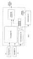
- the illustrated, exemplary mass flow controller 10is constructed and arranged to control flow through the MFC and monitor the accuracy of the MFC in real time.
- the mass flow controller 10includes two flow meters 12 and 14 , each independently generating a signal representing the measured rate of flow of gas through the MFC.
- the outputs of the two flow metersare provided to the system controller 16 .
- the system controller 16processes the two signals received from the two flow meters 12 and 14 and provides a control signal to the proportional control valve 18 based on the flow measured by one of the flow meters and a set point, and an indication (“alarm”) signal when a determination is made that the difference in the flow rates as measured by the two meters exceeds a predetermined threshold.
- FIG. 2A more detailed exemplary embodiment of a MFC, indicated generally at 20 , is shown in FIG. 2 .
- the MFC 20is constructed and arranged so as to control flow through the MFC and monitor the accuracy of the MFC in real time.
- gasis received at the input port 32 of block 28 , which in turn includes a conduit defining the main flow path 34 through the MFC to the outlet port 60 .
- the first flow meter 30is shown as a thermal mass flow meter.
- Thermal mass flow meterstypically include a thermal mass flow sensor 36 .
- the latterusually includes a bypass element 38 disposed in the bypass of the main flow path 34 of the gas flow through the block 28 .
- a U-shaped capillary tube 40has opposite ends respectively connected to the primary pathway at the upstream and downstream ends of the bypass element 38 .
- One or more resistance elements 42are used to measure flow through the capillary tube based on temperature measurements as a function, in the example, of the difference in resistances of the two resistance elements, which in turn is a function of the difference in the sense temperatures of the fluid, a measure of the mass flow rate.
- the bypass element 38is designed to ensure that gas flow through the bypass element 38 between the two ends of the capillary tube 40 is laminar. By maintaining laminar flow, the measured flow rate of gas through the capillary tube will be an accurate percentage of the flow through the main flow path 34 . Thus, the sensed flow rate through the capillary tube 40 will be an accurate measure of the flow rate though the MFC 20 and exiting outlet port 60 . Data representing the sensed flow rate is communicated to the system controller 16 .
- the second flow meter 50is shown as a differential pressure flow meter.
- the flow meter 50includes a flow restrictor 52 (for example, a critical flow nozzle or orifice), and a temperature sensor 54 and an upstream pressure sensor 56 arranged to measure the respective temperature and pressure of the gas flowing through the main flow path 34 upstream from the flow restrictor 52 .
- Data representing the sensed temperature and pressureis transmitted to the system controller for use in determining mass flow through the second flow meter 50 as function of these sensed measurements.
- a second or downstream pressure sensor 58is provided on the downstream side of the flow restrictor 52 .
- Data representing the sensed temperature, upstream pressure and downstream pressureis transmitted to the system controller 16 for determining the rate of mass flow through the second meter 50 as a function of the sensed measurements.
- the second measurement provided by the second flow meter 50(in both the choked and non-choked embodiments) is independent of the measurement provided by the first flow meter 30 .
- the system controller 16processes the outputs of the flow meters 70 and 72 so as to provide two flow measurements of the same flow through the MFC.
- flow meter 70is provided to a flow control unit 74 , which in turn applies a control signal to the proportional control valve 18 .
- a comparator 76is provided to compare the data representing the sensed flow measurements provided by the two meters 70 and 72 to provide an output signal as a function of and representing any difference between the two measurements. This output signal is compared to some threshold value (provided by threshold setting 80 ) by a threshold detector 78 .
- the threshold detectorprovides an alarm or indicating signal to alert the user that at least one of the meters is inaccurate, and that the MFC should be taken off line and further tested.
- the value of the threshold setting at 80can be provided in anyone of a number of ways including setting the value during the initial factory setup of the MFC, or user programmed.
- the threshold valuecan be set as a function of permissible tolerances in mass flow for the particular process with which the controller is used to deliver gas. Thus, some processes may permit greater tolerances in flow than others.
- first and second flow metershave been respectively described as a thermal mass flow meter and a differential pressure flow meter in FIG. 2 , they can be other types of flow meters as well, such as coriolis flow meter, magnetic flow meter or ultrasonic flow meter, depending on the application for which the MFC 20 is intended.
- the type of the first flow meteris different from that of the second flow meter
- the two flow meterscan be same type.
- both flow meterscan be either thermal mass flow meters or differential pressure flow meters.
- the first flow meter 30is located upstream to the control valve 18 and the second flow meter is located downstream to the control valve 18 , the locations of these two flow meters can be anywhere along the main flow path 34 of the MFC.
- both flow meterscan be upstream or downstream to the control valve 18 .
- the measurement from the first flow meter 70is used in the flow control unit 74 to control the MFC flow output and the measurement from the second flow meter 72 is used to verify the accuracy of the MFC in real time
- the measurement from the second flow meter 72can be used in the flow control unit 74 to control the flow output of the MFC 20 and the measurement from the first flow meter 70 be used for flow verification.
- the various embodiments of the MFC described hereincan be further configured to provide pressure insensitive operation and greater accuracy of control throughout the flow range of the MFC.
- pressure-based flow meters and thus pressure-based flow controlare insensitive to pressure disturbances or perturbations at the inlet of the MFC.
- pressure-based flow metersare not very accurate at low flow rates and low inlet pressures compared to thermal mass flow meters.
- the system controller 80is configured and arranged similarly to controller 16 of FIG. 2 , and further configured to switch between the two flow meters so as to control the position of the control valve 18 depending on the inlet pressure and flow rate through the MFC. In the FIG.
- the output of thermal-based flow meter 30can be used to control the control valve 18 for relatively low flow rates, and the output of the pressure-based flow meter 50 can be used to control the control valve for relatively high flow rates. More specifically, in one embodiment the cross over point or value is determined as a predetermined percentage of the full scale rate of flow to which the flow meters are designed. The predetermined percentage number is selected as a function of the expected range of pressures of the gas flowing through the meters.
- the output of the thermal-based flow meteris used to control the control valve 18 ; and when the flow rate through the MFC is determined to be more than the predetermined percentage of full scale, the output of the pressure-based flow meter is used to control the control valve 18 .
- Either flow metercan be used to control the control valve when the flow rate equals the cross-over value
- the usercan determine the cross over value in percentage of full scale, and provide the value as an input at 84 to the system controller 80 .
- itcan be provided during manufacture of the MFC.
- the controller 80will apply the output of the thermal-based flow-meter 30 to the control valve 18 , and for flow rates equal to and greater than 20% full scale, the controller 80 will apply the output of the pressure-based flow meter 50 to the control valve 18 .
- the thermal-based flow meter 30to control the MFC at relatively low flow rates, the accuracy of the flow control is improved in low flow rates.
- one additional feature of the disclosed MFCis to provide compensation for pressure disturbances that occur when the MFC is using thermal-based measurements to control flow. Specifically, when the mass flow control uses thermal flow sensor measurement within a low flow range and there is a pressure disturbance indicated by the sudden big flow deviation between the two flow sensors, the system controller senses the pressure disturbance, and with the controller 80 temporarily switches the flow control input from the thermal flow sensor measurement to the pressure-based flow measurement until the pressure transient period is gone.
- What constitutes a sudden “big flow deviation between the two flow sensors”can be determined, for example, by setting a threshold so that the deviation must exceed the threshold to be considered sufficient to warrant the change.
- the switchingoccurs from the thermal flow measurement to pressure-based flow measurement.
- the controller 80switches pressure-based flow measurement back to thermal flow measurement.
- the output of the thermal flow metertends to drift more than the pressure flow meter.
- the thermal flow meteris initially calibrated by the user or at the factory to provide zero offset, i.e. the output of the thermal flow meter is calibrated with a zero offset signal so that the output of the thermal flow meter is zero with zero input.
- the thermal flow metercan fall out of calibration and provide erroneous readings.
- the MFCcan also be configured to sense when the thermal flow meter falls out of calibration and automatically adjust the zero offset. This can be accomplished for example by assuming that should the readings of the two flow meters differ by a predetermined permitted tolerance or amount, the thermal flow meter is assumed to be out of calibration.
- the outputs of the thermal flow meter and pressure flow metercan be continually compared (even though only one flow meter controls the control value 18 at any one time during flow operations) to determine whether the thermal flow meter has fallen out of calibration. Should the output reading of the thermal flow meter vary from the output reading of the pressure flow meter by a predetermined amount, then a zero offset adjust signal can be provided by the system controller to the thermal flow meter as illustrated in FIG. 4 .
- the zero offset for the thermal flow sensoronly be adjusted when the flow is above a cross-over value of the crossover switch, e.g., 20% FS since the pressure-based sensor may not provide an accurate measurement for low flow range adjustment for the flow below the 20% FS crossover, and thus a comparison of the outputs of the two flow meters may not be accurate.
- a cross-over value of the crossover switche.g. 20% FS since the pressure-based sensor may not provide an accurate measurement for low flow range adjustment for the flow below the 20% FS crossover, and thus a comparison of the outputs of the two flow meters may not be accurate.
- the derivative of the two flow measurementscan be used to distinguish the compared difference between the two flow measurements due to pressure disturbances, and those due to a need to calibrate the offset. In the former situation, the derivative changes rather quickly due to the rapid change in the comparative difference between the two flow measurements, while in the latter situation the derivative changes rather slowly.
- the mass flow controlleremploying all of the features described herein has several advantages. Switching flow measurement based on the flow range for mass flow utilizes the best accuracy of both flow sensors. In addition, a pressure insensitive MFC is provided for the full flow range even without an upstream pressure sensor. Finally, self-correction can improve the accuracy of thermal flow sensor measurement which is prone to zero drift.
Landscapes
- Physics & Mathematics (AREA)
- General Physics & Mathematics (AREA)
- Fluid Mechanics (AREA)
- Engineering & Computer Science (AREA)
- Automation & Control Theory (AREA)
- Electromagnetism (AREA)
- Flow Control (AREA)
Abstract
Description
Claims (19)
Priority Applications (8)
| Application Number | Priority Date | Filing Date | Title |
|---|---|---|---|
| US14/180,063US9471066B2 (en) | 2012-01-20 | 2014-02-13 | System for and method of providing pressure insensitive self verifying mass flow controller |
| CN201580008399.0ACN106104402B (en) | 2014-02-13 | 2015-01-26 | System and method for providing a pressure insensitive self-verifying mass flow controller |
| SG11201606712XASG11201606712XA (en) | 2014-02-13 | 2015-01-26 | System for and method of providing pressure insensitive self verifying mass flow controller |
| KR1020167022177AKR102237868B1 (en) | 2014-02-13 | 2015-01-26 | System for and method of providing pressure insensitive self verifying mass flow controller |
| EP15748793.5AEP3105647B1 (en) | 2014-02-13 | 2015-01-26 | System for and method of providing pressure insensitive self verifying mass flow controller |
| JP2016550840AJP6484248B2 (en) | 2014-02-13 | 2015-01-26 | System and method for providing a pressure-insensitive self-verifying mass flow controller |
| PCT/US2015/012851WO2015123008A1 (en) | 2014-02-13 | 2015-01-26 | System for and method of providing pressure insensitive self verifying mass flow controller |
| TW104103651ATWI550376B (en) | 2014-02-13 | 2015-02-04 | Mass flow controller and method of controlling the mass flow rate of a gas with a mass flow controller |
Applications Claiming Priority (2)
| Application Number | Priority Date | Filing Date | Title |
|---|---|---|---|
| US13/354,988US9846074B2 (en) | 2012-01-20 | 2012-01-20 | System for and method of monitoring flow through mass flow controllers in real time |
| US14/180,063US9471066B2 (en) | 2012-01-20 | 2014-02-13 | System for and method of providing pressure insensitive self verifying mass flow controller |
Related Parent Applications (1)
| Application Number | Title | Priority Date | Filing Date |
|---|---|---|---|
| US13/354,988Continuation-In-PartUS9846074B2 (en) | 2012-01-20 | 2012-01-20 | System for and method of monitoring flow through mass flow controllers in real time |
Publications (2)
| Publication Number | Publication Date |
|---|---|
| US20140158211A1 US20140158211A1 (en) | 2014-06-12 |
| US9471066B2true US9471066B2 (en) | 2016-10-18 |
Family
ID=50879657
Family Applications (1)
| Application Number | Title | Priority Date | Filing Date |
|---|---|---|---|
| US14/180,063Active2032-10-17US9471066B2 (en) | 2012-01-20 | 2014-02-13 | System for and method of providing pressure insensitive self verifying mass flow controller |
Country Status (1)
| Country | Link |
|---|---|
| US (1) | US9471066B2 (en) |
Cited By (4)
| Publication number | Priority date | Publication date | Assignee | Title |
|---|---|---|---|---|
| US20160085241A1 (en)* | 2014-09-18 | 2016-03-24 | Chin-Tsung Lee | Flow detection device and numerical modeling method |
| US20170115148A1 (en)* | 2014-03-31 | 2017-04-27 | Hitachi Metals, Ltd. | Thermal mass flow rate measurement method, thermal mass flow meter using said method, and thermal mass flow controller using said thermal mass flow meter |
| US20240167633A1 (en)* | 2021-04-06 | 2024-05-23 | Robert Bosch Gmbh | Method for a communication between a fueling device and a vehicle |
| US12287655B2 (en) | 2022-12-16 | 2025-04-29 | Mks Instruments, Inc. | Method and apparatus for mass flow control |
Families Citing this family (20)
| Publication number | Priority date | Publication date | Assignee | Title |
|---|---|---|---|---|
| US9188989B1 (en) | 2011-08-20 | 2015-11-17 | Daniel T. Mudd | Flow node to deliver process gas using a remote pressure measurement device |
| US9958302B2 (en) | 2011-08-20 | 2018-05-01 | Reno Technologies, Inc. | Flow control system, method, and apparatus |
| US9910448B2 (en)* | 2013-03-14 | 2018-03-06 | Christopher Max Horwitz | Pressure-based gas flow controller with dynamic self-calibration |
| US10359308B2 (en) | 2014-12-12 | 2019-07-23 | Natural Gas Solutions North America, Llc | Flow meter and a method of calibration |
| EP3118711B1 (en) | 2015-07-17 | 2021-01-13 | Sensirion AG | Inlet pressure perturbation insensitive mass flow controller |
| US10684159B2 (en)* | 2016-06-27 | 2020-06-16 | Applied Materials, Inc. | Methods, systems, and apparatus for mass flow verification based on choked flow |
| US10303189B2 (en) | 2016-06-30 | 2019-05-28 | Reno Technologies, Inc. | Flow control system, method, and apparatus |
| US10838437B2 (en) | 2018-02-22 | 2020-11-17 | Ichor Systems, Inc. | Apparatus for splitting flow of process gas and method of operating same |
| US11144075B2 (en) | 2016-06-30 | 2021-10-12 | Ichor Systems, Inc. | Flow control system, method, and apparatus |
| US10679880B2 (en) | 2016-09-27 | 2020-06-09 | Ichor Systems, Inc. | Method of achieving improved transient response in apparatus for controlling flow and system for accomplishing same |
| US10663337B2 (en) | 2016-12-30 | 2020-05-26 | Ichor Systems, Inc. | Apparatus for controlling flow and method of calibrating same |
| JP6913498B2 (en)* | 2017-04-18 | 2021-08-04 | 東京エレクトロン株式会社 | Method of obtaining the output flow rate of the flow rate controller and method of processing the object to be processed |
| EP3421947B1 (en) | 2017-06-30 | 2019-08-07 | Sensirion AG | Operation method for flow sensor device |
| US12235144B2 (en) | 2020-09-17 | 2025-02-25 | Applied Materials, Inc.—Robotics | Micro-electromechanical device for use in a flow control apparatus |
| US11772958B2 (en)* | 2020-09-17 | 2023-10-03 | Applied Materials, Inc. | Mass flow control based on micro-electromechanical devices |
| US11899477B2 (en) | 2021-03-03 | 2024-02-13 | Ichor Systems, Inc. | Fluid flow control system comprising a manifold assembly |
| CN115144057A (en)* | 2021-03-31 | 2022-10-04 | 高准有限公司 | System and method for zero calibration and mass flow meter |
| CN117425810A (en) | 2021-05-26 | 2024-01-19 | 奥伊格斯特/弗里斯马格股份公司 | Metering device for setting and/or regulating a gas flow, method for setting and/or regulating a gas flow, and household appliance assembly |
| CN115371751B (en)* | 2022-07-20 | 2024-10-11 | 中国船舶重工集团公司第七一九研究所 | High-pressure air mass flowmeter based on outlet pressure |
| US12393209B2 (en)* | 2024-01-19 | 2025-08-19 | Mks, Inc. | Methods and apparatus for reporting inlet pressure in mass flow controllers |
Citations (45)
| Publication number | Priority date | Publication date | Assignee | Title |
|---|---|---|---|---|
| US3952759A (en) | 1974-08-14 | 1976-04-27 | M & J Valve Company | Liquid line break control system and method |
| US4487213A (en) | 1982-09-09 | 1984-12-11 | Omicron Technology Corporation | Mass flow controller apparatus |
| JPH03166611A (en) | 1989-11-27 | 1991-07-18 | Nec Corp | Mass flow rate controller |
| JPH03211601A (en) | 1990-01-17 | 1991-09-17 | Fujitsu Ltd | Gas flow rate controller |
| JPH08312908A (en) | 1995-05-15 | 1996-11-26 | Tlv Co Ltd | Dryness controller for steam |
| US6394120B1 (en) | 2000-10-06 | 2002-05-28 | Scales Air Compressor | Method and control system for controlling multiple compressors |
| US20020083984A1 (en) | 2000-12-28 | 2002-07-04 | International Business Machines Corporation | System for and method of monitoring the flow of semiconductor process gases from a gas delivery system |
| US20030039550A1 (en) | 2001-08-20 | 2003-02-27 | Wichert Ernest J. | Method and control system for controlling multiple throttled inlet rotary screw compressors |
| JP2003167630A (en) | 2001-12-04 | 2003-06-13 | Ckd Corp | Flow control device and flow control method |
| CN1513110A (en) | 2001-05-30 | 2004-07-14 | Flowmeter verification device and method | |
| JP2004246826A (en) | 2003-02-17 | 2004-09-02 | Stec Inc | Mass flow controller |
| TWI223056B (en) | 2002-07-19 | 2004-11-01 | Celerity Group Inc | Methods and apparatus for pressure compensation in a mass flow controller |
| US20060278276A1 (en) | 2004-06-21 | 2006-12-14 | Makoto Tanaka | Flow controller and its regulation method |
| US20060283254A1 (en) | 2005-03-25 | 2006-12-21 | Mks Instruments, Inc. | Critical flow based mass flow verifier |
| US7204158B2 (en) | 2004-07-07 | 2007-04-17 | Parker-Hannifin Corporation | Flow control apparatus and method with internally isothermal control volume for flow verification |
| US20070113641A1 (en) | 2005-11-22 | 2007-05-24 | Mks Instruments, Inc. | Vertical mount mass flow sensor |
| CN101208641A (en) | 2005-06-27 | 2008-06-25 | 株式会社富士金 | Variable flow range flow control device |
| CN101238357A (en) | 2005-06-22 | 2008-08-06 | 洛斯罗布莱斯广告公司 | Mass velocity and area weighted averaging fluid composition sampler and mass flow meter |
| US20090112504A1 (en) | 2005-03-25 | 2009-04-30 | Mks Instruments, Inc. | High Accuracy Mass Flow Verifier with Multiple Inlets |
| US20090183548A1 (en) | 2008-01-18 | 2009-07-23 | Pivotal Systems Corporation | Method and apparatus for in situ testing of gas flow controllers |
| US20090212847A1 (en) | 2008-02-22 | 2009-08-27 | Brooks Instrument, Llc | System and method for sensor thermal drift offset compensation |
| US20090266139A1 (en) | 2008-04-25 | 2009-10-29 | Applied Materials, Inc | Real time lead-line characterization for mfc flow verification |
| US7636640B2 (en) | 2006-09-05 | 2009-12-22 | Brooks Instrument, Llc | Multi-gas flow device |
| US7654151B2 (en) | 2005-05-10 | 2010-02-02 | Agar Corporation Ltd. | Method and apparatus for measuring multi-streams and multi-phase flow |
| US7658204B2 (en) | 2002-11-15 | 2010-02-09 | Renesas Technology Corp. | Semiconductor manufacturing apparatus enabling inspection of mass flow controller maintaining connection thereto |
| WO2010018191A1 (en) | 2008-08-13 | 2010-02-18 | Shell Internationale Research Maatschappij B.V. | Method for controlling a gas flow between a plurality of gas streams |
| US20100080262A1 (en) | 2008-09-26 | 2010-04-01 | Advanced Energy Industries, Inc. | Method and system for operating a mass flow controller |
| US20100125424A1 (en) | 2008-11-18 | 2010-05-20 | Mks Instruments, Inc. | Dual-Mode Mass Flow Verification and Mass Flow Delivery System and Method |
| CN101796378A (en) | 2007-06-27 | 2010-08-04 | Mks仪器公司 | Mass flow verifier capable of providing different volumes and related methods |
| US20100209859A1 (en) | 2009-02-18 | 2010-08-19 | Shin-Etsu Chemical Co., Ltd. | Apparatus and method for supplying hydrogen gas, and quartz glass manufacturing apparatus |
| US20110022334A1 (en) | 2009-07-24 | 2011-01-27 | Junhua Ding | Upstream volume mass flow verification systems and methods field of the disclosure |
| WO2011047361A1 (en) | 2009-10-15 | 2011-04-21 | Pivotal Systems Corporation | Method and apparatus for gas flow control |
| DE102009046758A1 (en) | 2009-11-17 | 2011-05-19 | Endress + Hauser Process Solutions Ag | Self-monitoring flowmeter assembly and method of operation |
| US20110139271A1 (en) | 2008-06-04 | 2011-06-16 | Fujikin Incorporated | Automatic pressure regulator for flow rate regulator |
| US20110284500A1 (en) | 2010-05-21 | 2011-11-24 | Illinois Tool Works Inc. | Welding gas leak detection system and method |
| US8109289B2 (en) | 2008-12-16 | 2012-02-07 | Honeywell International Inc. | System and method for decentralized balancing of hydronic networks |
| US20120132291A1 (en) | 2010-11-29 | 2012-05-31 | Pivotal Systems Corporation | Transient measurements of mass flow controllers |
| US20120216888A1 (en) | 2011-02-25 | 2012-08-30 | Mks Instruments, Inc. | System for and Method of Fast Pulse Gas Delivery |
| US8265888B2 (en) | 2009-12-09 | 2012-09-11 | Pivotal Systems Corporation | Method and apparatus for enhancing in-situ gas flow measurement performance |
| US8271210B2 (en) | 2009-12-09 | 2012-09-18 | Pivotal Systems Corporation | Method and apparatus for enhancing in-situ gas flow measurement performance |
| US8271211B2 (en) | 2009-12-09 | 2012-09-18 | Pivotal Systems Corporation | Method and apparatus for enhancing in-situ gas flow measurement performance |
| US8356623B2 (en) | 2008-12-25 | 2013-01-22 | Horiba Stec, Co., Ltd. | Mass flow meter and mass flow controller |
| US20130186486A1 (en) | 2012-01-20 | 2013-07-25 | Junhua Ding | System for and method of monitoring flow through mass flow controllers in real time |
| US8504318B2 (en) | 2008-03-05 | 2013-08-06 | Brooks Instruments, Llc | System, method and computer program for determining fluid flow rate using a pressure sensor and a thermal mass flow sensor |
| WO2013134141A2 (en) | 2012-03-07 | 2013-09-12 | Illinois Tool Works Inc. | System and mehtod for using a model for improving control of a mass flow controller |
- 2014
- 2014-02-13USUS14/180,063patent/US9471066B2/enactiveActive
Patent Citations (55)
| Publication number | Priority date | Publication date | Assignee | Title |
|---|---|---|---|---|
| US3952759A (en) | 1974-08-14 | 1976-04-27 | M & J Valve Company | Liquid line break control system and method |
| US4487213A (en) | 1982-09-09 | 1984-12-11 | Omicron Technology Corporation | Mass flow controller apparatus |
| JPH03166611A (en) | 1989-11-27 | 1991-07-18 | Nec Corp | Mass flow rate controller |
| JPH03211601A (en) | 1990-01-17 | 1991-09-17 | Fujitsu Ltd | Gas flow rate controller |
| JPH08312908A (en) | 1995-05-15 | 1996-11-26 | Tlv Co Ltd | Dryness controller for steam |
| US6394120B1 (en) | 2000-10-06 | 2002-05-28 | Scales Air Compressor | Method and control system for controlling multiple compressors |
| US20020083984A1 (en) | 2000-12-28 | 2002-07-04 | International Business Machines Corporation | System for and method of monitoring the flow of semiconductor process gases from a gas delivery system |
| US6439253B1 (en) | 2000-12-28 | 2002-08-27 | International Business Machines Corporation | System for and method of monitoring the flow of semiconductor process gases from a gas delivery system |
| CN1513110A (en) | 2001-05-30 | 2004-07-14 | Flowmeter verification device and method | |
| US20030039550A1 (en) | 2001-08-20 | 2003-02-27 | Wichert Ernest J. | Method and control system for controlling multiple throttled inlet rotary screw compressors |
| JP2003167630A (en) | 2001-12-04 | 2003-06-13 | Ckd Corp | Flow control device and flow control method |
| TWI223056B (en) | 2002-07-19 | 2004-11-01 | Celerity Group Inc | Methods and apparatus for pressure compensation in a mass flow controller |
| US8751180B2 (en) | 2002-07-19 | 2014-06-10 | Brooks Instrument Llc | Methods and apparatus for pressure compensation in a mass flow controller |
| US7658204B2 (en) | 2002-11-15 | 2010-02-09 | Renesas Technology Corp. | Semiconductor manufacturing apparatus enabling inspection of mass flow controller maintaining connection thereto |
| JP2004246826A (en) | 2003-02-17 | 2004-09-02 | Stec Inc | Mass flow controller |
| US20060278276A1 (en) | 2004-06-21 | 2006-12-14 | Makoto Tanaka | Flow controller and its regulation method |
| US7204158B2 (en) | 2004-07-07 | 2007-04-17 | Parker-Hannifin Corporation | Flow control apparatus and method with internally isothermal control volume for flow verification |
| US20060283254A1 (en) | 2005-03-25 | 2006-12-21 | Mks Instruments, Inc. | Critical flow based mass flow verifier |
| US20090112504A1 (en) | 2005-03-25 | 2009-04-30 | Mks Instruments, Inc. | High Accuracy Mass Flow Verifier with Multiple Inlets |
| US7654151B2 (en) | 2005-05-10 | 2010-02-02 | Agar Corporation Ltd. | Method and apparatus for measuring multi-streams and multi-phase flow |
| CN101238357A (en) | 2005-06-22 | 2008-08-06 | 洛斯罗布莱斯广告公司 | Mass velocity and area weighted averaging fluid composition sampler and mass flow meter |
| CN101208641A (en) | 2005-06-27 | 2008-06-25 | 株式会社富士金 | Variable flow range flow control device |
| US20070113641A1 (en) | 2005-11-22 | 2007-05-24 | Mks Instruments, Inc. | Vertical mount mass flow sensor |
| US7636640B2 (en) | 2006-09-05 | 2009-12-22 | Brooks Instrument, Llc | Multi-gas flow device |
| CN101796378A (en) | 2007-06-27 | 2010-08-04 | Mks仪器公司 | Mass flow verifier capable of providing different volumes and related methods |
| US7823436B2 (en) | 2008-01-18 | 2010-11-02 | Pivotal Systems Corporation | Method and apparatus for in situ testing of gas flow controllers |
| US20120304781A1 (en) | 2008-01-18 | 2012-12-06 | Pivotal Systems Corporation | Method and apparatus for in situ testing of gas flow controllers |
| US20090183548A1 (en) | 2008-01-18 | 2009-07-23 | Pivotal Systems Corporation | Method and apparatus for in situ testing of gas flow controllers |
| US20090183549A1 (en) | 2008-01-18 | 2009-07-23 | Pivotal Systems Corporation | Method and apparatus for in situ testing of gas flow controllers |
| US8240324B2 (en) | 2008-01-18 | 2012-08-14 | Pivotal Systems Corporation | Method and apparatus for in situ testing of gas flow controllers |
| US20090212847A1 (en) | 2008-02-22 | 2009-08-27 | Brooks Instrument, Llc | System and method for sensor thermal drift offset compensation |
| US8504318B2 (en) | 2008-03-05 | 2013-08-06 | Brooks Instruments, Llc | System, method and computer program for determining fluid flow rate using a pressure sensor and a thermal mass flow sensor |
| US20090266139A1 (en) | 2008-04-25 | 2009-10-29 | Applied Materials, Inc | Real time lead-line characterization for mfc flow verification |
| US20110139271A1 (en) | 2008-06-04 | 2011-06-16 | Fujikin Incorporated | Automatic pressure regulator for flow rate regulator |
| CN102057340B (en) | 2008-06-04 | 2014-07-16 | 株式会社富士金 | Automatic pressure regulator for flow regulator |
| JP2011530755A (en) | 2008-08-13 | 2011-12-22 | シエル・インターナシヨネイル・リサーチ・マーチヤツピイ・ベー・ウイ | Method for controlling the gas flow rate between multiple gas streams |
| WO2010018191A1 (en) | 2008-08-13 | 2010-02-18 | Shell Internationale Research Maatschappij B.V. | Method for controlling a gas flow between a plurality of gas streams |
| CN102124418A (en) | 2008-08-13 | 2011-07-13 | 国际壳牌研究有限公司 | Method for controlling a gas flow between a plurality of gas streams |
| US20100080262A1 (en) | 2008-09-26 | 2010-04-01 | Advanced Energy Industries, Inc. | Method and system for operating a mass flow controller |
| US20100125424A1 (en) | 2008-11-18 | 2010-05-20 | Mks Instruments, Inc. | Dual-Mode Mass Flow Verification and Mass Flow Delivery System and Method |
| US8109289B2 (en) | 2008-12-16 | 2012-02-07 | Honeywell International Inc. | System and method for decentralized balancing of hydronic networks |
| US8356623B2 (en) | 2008-12-25 | 2013-01-22 | Horiba Stec, Co., Ltd. | Mass flow meter and mass flow controller |
| US20100209859A1 (en) | 2009-02-18 | 2010-08-19 | Shin-Etsu Chemical Co., Ltd. | Apparatus and method for supplying hydrogen gas, and quartz glass manufacturing apparatus |
| US20110022334A1 (en) | 2009-07-24 | 2011-01-27 | Junhua Ding | Upstream volume mass flow verification systems and methods field of the disclosure |
| US20110108126A1 (en) | 2009-10-15 | 2011-05-12 | Pivotal Systems Corporation | Method and apparatus for gas flow control |
| WO2011047361A1 (en) | 2009-10-15 | 2011-04-21 | Pivotal Systems Corporation | Method and apparatus for gas flow control |
| DE102009046758A1 (en) | 2009-11-17 | 2011-05-19 | Endress + Hauser Process Solutions Ag | Self-monitoring flowmeter assembly and method of operation |
| US8271211B2 (en) | 2009-12-09 | 2012-09-18 | Pivotal Systems Corporation | Method and apparatus for enhancing in-situ gas flow measurement performance |
| US8271210B2 (en) | 2009-12-09 | 2012-09-18 | Pivotal Systems Corporation | Method and apparatus for enhancing in-situ gas flow measurement performance |
| US8265888B2 (en) | 2009-12-09 | 2012-09-11 | Pivotal Systems Corporation | Method and apparatus for enhancing in-situ gas flow measurement performance |
| US20110284500A1 (en) | 2010-05-21 | 2011-11-24 | Illinois Tool Works Inc. | Welding gas leak detection system and method |
| US20120132291A1 (en) | 2010-11-29 | 2012-05-31 | Pivotal Systems Corporation | Transient measurements of mass flow controllers |
| US20120216888A1 (en) | 2011-02-25 | 2012-08-30 | Mks Instruments, Inc. | System for and Method of Fast Pulse Gas Delivery |
| US20130186486A1 (en) | 2012-01-20 | 2013-07-25 | Junhua Ding | System for and method of monitoring flow through mass flow controllers in real time |
| WO2013134141A2 (en) | 2012-03-07 | 2013-09-12 | Illinois Tool Works Inc. | System and mehtod for using a model for improving control of a mass flow controller |
Non-Patent Citations (10)
| Title |
|---|
| Brooks Instrument, Data Sheet GF135 Digital Mass Flow Controller, 10 pages (2013). |
| Brooks Instrument, Installation and Operation Manual, X-TMF-GF100-Series-MFC-eng, Part No. 541B137AAG, 82 pages (2013). |
| International Search Report and the Written Opinion dated Feb. 11, 2014 from corresponding PCT Application No. PCT/US2013/057184. |
| International Search Report and the Written Opinion dated Mar. 11, 2013 from Corresponding PCT Application No. PCT/US2013/020790. |
| International Search Report and the Written Opinion from corresponding PCT Application No. PCT/US2015/012851 dated Apr. 28, 2015. |
| International Search Report and the Written Opinion from corresponding PCT Application No. PCT/US2015/015831 dated May 22, 2015. |
| Non-Final Office Action dated Jun. 29, 2015 from corresponding U.S. Appl. No. 13/354,988. |
| Office Action dated Aug. 18, 2015 from corresponding Japanese Application No. 2014-553321. |
| Office Action dated Oct. 2, 2015 from corresponding Taiwan Patent Application No. 104106156. |
| Office Action dated Sep. 23, 2015 from corresponding Korean Patent Application No. 10-2014-7022413. |
Cited By (6)
| Publication number | Priority date | Publication date | Assignee | Title |
|---|---|---|---|---|
| US20170115148A1 (en)* | 2014-03-31 | 2017-04-27 | Hitachi Metals, Ltd. | Thermal mass flow rate measurement method, thermal mass flow meter using said method, and thermal mass flow controller using said thermal mass flow meter |
| US10508943B2 (en)* | 2014-03-31 | 2019-12-17 | Hitachi Metals, Ltd. | Thermal mass flow rate measurement method, thermal mass flow meter using said method, and thermal mass flow controller using said thermal mass flow meter |
| US20160085241A1 (en)* | 2014-09-18 | 2016-03-24 | Chin-Tsung Lee | Flow detection device and numerical modeling method |
| US20240167633A1 (en)* | 2021-04-06 | 2024-05-23 | Robert Bosch Gmbh | Method for a communication between a fueling device and a vehicle |
| US12305811B2 (en)* | 2021-04-06 | 2025-05-20 | Robert Bosch Gmbh | Method for a communication between a fueling device and a vehicle |
| US12287655B2 (en) | 2022-12-16 | 2025-04-29 | Mks Instruments, Inc. | Method and apparatus for mass flow control |
Also Published As
| Publication number | Publication date |
|---|---|
| US20140158211A1 (en) | 2014-06-12 |
Similar Documents
| Publication | Publication Date | Title |
|---|---|---|
| US9471066B2 (en) | System for and method of providing pressure insensitive self verifying mass flow controller | |
| US10606285B2 (en) | System for and method of monitoring flow through mass flow controllers in real time | |
| US9846074B2 (en) | System for and method of monitoring flow through mass flow controllers in real time | |
| EP3117137B1 (en) | System for monitoring flow through mass flow controllers in real time | |
| EP3105647B1 (en) | System for and method of providing pressure insensitive self verifying mass flow controller | |
| EP2901227B1 (en) | Method and apparatus for self verification of pressure based mass flow controllers | |
| US8015995B2 (en) | System and method for flow monitoring and control | |
| JP7131561B2 (en) | Mass flow control system and semiconductor manufacturing equipment and vaporizer including the system | |
| US20250053182A1 (en) | Method and Apparatus for Automatic Self Calibration of Mass Flow Controller |
Legal Events
| Date | Code | Title | Description |
|---|---|---|---|
| AS | Assignment | Owner name:MKS INSTRUMENTS, INC., MARYLAND Free format text:ASSIGNMENT OF ASSIGNORS INTEREST;ASSIGNORS:DING, JUNHUA;L'BASSI, MICHAEL;REEL/FRAME:032214/0939 Effective date:20140212 | |
| AS | Assignment | Owner name:MKS INSTRUMENTS, INC., MASSACHUSETTS Free format text:ASSIGNMENT OF ASSIGNORS INTEREST;ASSIGNORS:DING, JUNHUA;L'BASSI, MICHAEL;REEL/FRAME:032462/0238 Effective date:20140212 | |
| AS | Assignment | Owner name:BARCLAYS BANK PLC, NEW YORK Free format text:SECURITY AGREEMENT;ASSIGNORS:MKS INSTRUMENTS, INC.;NEWPORT CORPORATION;REEL/FRAME:038663/0139 Effective date:20160429 Owner name:DEUTSCHE BANK AG NEW YORK BRANCH, NEW YORK Free format text:SECURITY AGREEMENT;ASSIGNORS:MKS INSTRUMENTS, INC.;NEWPORT CORPORATION;REEL/FRAME:038663/0265 Effective date:20160429 | |
| STCF | Information on status: patent grant | Free format text:PATENTED CASE | |
| AS | Assignment | Owner name:BARCLAYS BANK PLC, AS COLLATERAL AGENT, NEW YORK Free format text:PATENT SECURITY AGREEMENT (ABL);ASSIGNORS:ELECTRO SCIENTIFIC INDUSTRIES, INC.;MKS INSTRUMENTS, INC.;NEWPORT CORPORATION;REEL/FRAME:048211/0312 Effective date:20190201 Owner name:NEWPORT CORPORATION, CALIFORNIA Free format text:RELEASE BY SECURED PARTY;ASSIGNOR:DEUTSCHE BANK AG NEW YORK BRANCH;REEL/FRAME:048226/0095 Effective date:20190201 Owner name:MKS INSTRUMENTS, INC., MASSACHUSETTS Free format text:RELEASE BY SECURED PARTY;ASSIGNOR:DEUTSCHE BANK AG NEW YORK BRANCH;REEL/FRAME:048226/0095 Effective date:20190201 | |
| MAFP | Maintenance fee payment | Free format text:PAYMENT OF MAINTENANCE FEE, 4TH YEAR, LARGE ENTITY (ORIGINAL EVENT CODE: M1551); ENTITY STATUS OF PATENT OWNER: LARGE ENTITY Year of fee payment:4 | |
| AS | Assignment | Owner name:BARCLAYS BANK PLC, AS COLLATERAL AGENT, NEW YORK Free format text:CORRECTIVE ASSIGNMENT TO CORRECT THE REMOVE U.S. PATENT NO.7,919,646 PREVIOUSLY RECORDED ON REEL 048211 FRAME 0312. ASSIGNOR(S) HEREBY CONFIRMS THE PATENT SECURITY AGREEMENT (ABL);ASSIGNORS:ELECTRO SCIENTIFIC INDUSTRIES, INC.;MKS INSTRUMENTS, INC.;NEWPORT CORPORATION;REEL/FRAME:055668/0687 Effective date:20190201 | |
| AS | Assignment | Owner name:JPMORGAN CHASE BANK, N.A., AS COLLATERAL AGENT, ILLINOIS Free format text:SECURITY INTEREST;ASSIGNORS:MKS INSTRUMENTS, INC.;NEWPORT CORPORATION;ELECTRO SCIENTIFIC INDUSTRIES, INC.;REEL/FRAME:061572/0069 Effective date:20220817 | |
| AS | Assignment | Owner name:ELECTRO SCIENTIFIC INDUSTRIES, INC., OREGON Free format text:RELEASE BY SECURED PARTY;ASSIGNOR:BARCLAYS BANK PLC;REEL/FRAME:063009/0001 Effective date:20220817 Owner name:NEWPORT CORPORATION, MASSACHUSETTS Free format text:RELEASE BY SECURED PARTY;ASSIGNOR:BARCLAYS BANK PLC;REEL/FRAME:063009/0001 Effective date:20220817 Owner name:MKS INSTRUMENTS, INC., MASSACHUSETTS Free format text:RELEASE BY SECURED PARTY;ASSIGNOR:BARCLAYS BANK PLC;REEL/FRAME:063009/0001 Effective date:20220817 Owner name:ELECTRO SCIENTIFIC INDUSTRIES, INC., OREGON Free format text:RELEASE BY SECURED PARTY;ASSIGNOR:BARCLAYS BANK PLC;REEL/FRAME:062739/0001 Effective date:20220817 Owner name:NEWPORT CORPORATION, MASSACHUSETTS Free format text:RELEASE BY SECURED PARTY;ASSIGNOR:BARCLAYS BANK PLC;REEL/FRAME:062739/0001 Effective date:20220817 Owner name:MKS INSTRUMENTS, INC., MASSACHUSETTS Free format text:RELEASE BY SECURED PARTY;ASSIGNOR:BARCLAYS BANK PLC;REEL/FRAME:062739/0001 Effective date:20220817 | |
| MAFP | Maintenance fee payment | Free format text:PAYMENT OF MAINTENANCE FEE, 8TH YEAR, LARGE ENTITY (ORIGINAL EVENT CODE: M1552); ENTITY STATUS OF PATENT OWNER: LARGE ENTITY Year of fee payment:8 |