US9468442B2 - Vascular remodeling device - Google Patents
Vascular remodeling deviceDownload PDFInfo
- Publication number
- US9468442B2 US9468442B2US13/016,855US201113016855AUS9468442B2US 9468442 B2US9468442 B2US 9468442B2US 201113016855 AUS201113016855 AUS 201113016855AUS 9468442 B2US9468442 B2US 9468442B2
- Authority
- US
- United States
- Prior art keywords
- filaments
- catheter
- aneurysm
- distal
- bifurcation
- Prior art date
- Legal status (The legal status is an assumption and is not a legal conclusion. Google has not performed a legal analysis and makes no representation as to the accuracy of the status listed.)
- Expired - Fee Related, expires
Links
- 208000032594Vascular RemodelingDiseases0.000titledescription22
- 206010002329AneurysmDiseases0.000claimsabstractdescription169
- 239000000463materialSubstances0.000claimsabstractdescription115
- 230000003073embolic effectEffects0.000claimsabstractdescription34
- 230000010412perfusionEffects0.000claimsabstractdescription22
- 238000000034methodMethods0.000claimsdescription73
- 239000012530fluidSubstances0.000claimsdescription25
- 235000009854Cucurbita moschataNutrition0.000abstractdescription9
- 240000001980Cucurbita pepoSpecies0.000abstractdescription5
- 235000000832AyoteNutrition0.000abstractdescription3
- 235000009804Cucurbita pepo subsp pepoNutrition0.000abstractdescription3
- 235000015136pumpkinNutrition0.000abstractdescription3
- BASFCYQUMIYNBI-UHFFFAOYSA-NplatinumChemical compound[Pt]BASFCYQUMIYNBI-UHFFFAOYSA-N0.000description70
- 230000010102embolizationEffects0.000description45
- 210000005166vasculatureAnatomy0.000description39
- 229910001000nickel titaniumInorganic materials0.000description33
- HLXZNVUGXRDIFK-UHFFFAOYSA-Nnickel titaniumChemical compound[Ti].[Ti].[Ti].[Ti].[Ti].[Ti].[Ti].[Ti].[Ti].[Ti].[Ti].[Ni].[Ni].[Ni].[Ni].[Ni].[Ni].[Ni].[Ni].[Ni].[Ni].[Ni].[Ni].[Ni].[Ni]HLXZNVUGXRDIFK-UHFFFAOYSA-N0.000description33
- 229910052697platinumInorganic materials0.000description33
- 238000007634remodelingMethods0.000description32
- 230000007246mechanismEffects0.000description25
- 238000000576coating methodMethods0.000description22
- 239000011248coating agentSubstances0.000description18
- 239000007788liquidSubstances0.000description18
- 239000003550markerSubstances0.000description15
- 239000008280bloodSubstances0.000description12
- 210000004369bloodAnatomy0.000description12
- 229910052715tantalumInorganic materials0.000description12
- GUVRBAGPIYLISA-UHFFFAOYSA-Ntantalum atomChemical compound[Ta]GUVRBAGPIYLISA-UHFFFAOYSA-N0.000description12
- 208000012287ProlapseDiseases0.000description11
- 230000008569processEffects0.000description9
- BQCADISMDOOEFD-UHFFFAOYSA-NSilverChemical compound[Ag]BQCADISMDOOEFD-UHFFFAOYSA-N0.000description8
- 230000008901benefitEffects0.000description8
- PCHJSUWPFVWCPO-UHFFFAOYSA-NgoldChemical compound[Au]PCHJSUWPFVWCPO-UHFFFAOYSA-N0.000description8
- 229910052737goldInorganic materials0.000description8
- 239000010931goldSubstances0.000description8
- 230000002401inhibitory effectEffects0.000description8
- ZONODCCBXBRQEZ-UHFFFAOYSA-Nplatinum tungstenChemical compound[W].[Pt]ZONODCCBXBRQEZ-UHFFFAOYSA-N0.000description8
- 229920000642polymerPolymers0.000description8
- 239000012781shape memory materialSubstances0.000description8
- 229910052709silverInorganic materials0.000description8
- 239000004332silverSubstances0.000description8
- -1MP35N®Inorganic materials0.000description6
- 238000005476solderingMethods0.000description6
- 238000003466weldingMethods0.000description6
- 229910000684Cobalt-chromeInorganic materials0.000description5
- 229910045601alloyInorganic materials0.000description5
- 239000000956alloySubstances0.000description5
- 238000005229chemical vapour depositionMethods0.000description5
- 239000010952cobalt-chromeSubstances0.000description5
- 230000007423decreaseEffects0.000description5
- 238000005240physical vapour depositionMethods0.000description5
- 240000004244Cucurbita moschataSpecies0.000description4
- IAZDPXIOMUYVGZ-UHFFFAOYSA-NDimethylsulphoxideChemical compoundCS(C)=OIAZDPXIOMUYVGZ-UHFFFAOYSA-N0.000description4
- 230000009471actionEffects0.000description4
- 230000007797corrosionEffects0.000description4
- 238000005260corrosionMethods0.000description4
- 230000008878couplingEffects0.000description4
- 238000010168coupling processMethods0.000description4
- 238000005859coupling reactionMethods0.000description4
- 238000007747platingMethods0.000description4
- 229920000954PolyglycolidePolymers0.000description3
- FAPWRFPIFSIZLT-UHFFFAOYSA-MSodium chlorideChemical compound[Na+].[Cl-]FAPWRFPIFSIZLT-UHFFFAOYSA-M0.000description3
- 210000003484anatomyAnatomy0.000description3
- 230000017531blood circulationEffects0.000description3
- 238000005520cutting processMethods0.000description3
- 238000010438heat treatmentMethods0.000description3
- 230000003993interactionEffects0.000description3
- 238000004519manufacturing processMethods0.000description3
- 230000004048modificationEffects0.000description3
- 238000012986modificationMethods0.000description3
- 239000004633polyglycolic acidSubstances0.000description3
- 239000011780sodium chlorideSubstances0.000description3
- 235000003949Cucurbita mixtaNutrition0.000description2
- 235000009852Cucurbita pepoNutrition0.000description2
- 239000004677NylonSubstances0.000description2
- 235000007919giant pumpkinNutrition0.000description2
- 238000003306harvestingMethods0.000description2
- 229920001778nylonPolymers0.000description2
- 229920000728polyesterPolymers0.000description2
- 229920001343polytetrafluoroethylenePolymers0.000description2
- 239000004810polytetrafluoroethyleneSubstances0.000description2
- 239000011148porous materialSubstances0.000description2
- 238000007493shaping processMethods0.000description2
- 235000020354squashNutrition0.000description2
- 240000002234Allium sativumSpecies0.000description1
- 208000031104Arterial Occlusive diseaseDiseases0.000description1
- 235000011297Brassica napobrassicaNutrition0.000description1
- 241000219192Brassica napus subsp. rapiferaSpecies0.000description1
- 244000241235Citrullus lanatusSpecies0.000description1
- 235000012828Citrullus lanatus var citroidesNutrition0.000description1
- 241000882279Gonatus onyxSpecies0.000description1
- 201000008450Intracranial aneurysmDiseases0.000description1
- 239000002253acidSubstances0.000description1
- 208000021328arterial occlusionDiseases0.000description1
- 230000015572biosynthetic processEffects0.000description1
- 230000008859changeEffects0.000description1
- 239000007795chemical reaction productSubstances0.000description1
- 238000000151depositionMethods0.000description1
- 235000004611garlicNutrition0.000description1
- 239000000203mixtureSubstances0.000description1
- 239000004626polylactic acidSubstances0.000description1
- 238000009958sewingMethods0.000description1
- 238000004904shorteningMethods0.000description1
- 239000007787solidSubstances0.000description1
- 239000000126substanceSubstances0.000description1
- 239000010409thin filmSubstances0.000description1
Images


Classifications
- A—HUMAN NECESSITIES
- A61—MEDICAL OR VETERINARY SCIENCE; HYGIENE
- A61B—DIAGNOSIS; SURGERY; IDENTIFICATION
- A61B17/00—Surgical instruments, devices or methods
- A61B17/12—Surgical instruments, devices or methods for ligaturing or otherwise compressing tubular parts of the body, e.g. blood vessels or umbilical cord
- A61B17/12022—Occluding by internal devices, e.g. balloons or releasable wires
- A61B17/12099—Occluding by internal devices, e.g. balloons or releasable wires characterised by the location of the occluder
- A61B17/12109—Occluding by internal devices, e.g. balloons or releasable wires characterised by the location of the occluder in a blood vessel
- A61B17/12113—Occluding by internal devices, e.g. balloons or releasable wires characterised by the location of the occluder in a blood vessel within an aneurysm
- A61B17/12118—Occluding by internal devices, e.g. balloons or releasable wires characterised by the location of the occluder in a blood vessel within an aneurysm for positioning in conjunction with a stent
- A—HUMAN NECESSITIES
- A61—MEDICAL OR VETERINARY SCIENCE; HYGIENE
- A61B—DIAGNOSIS; SURGERY; IDENTIFICATION
- A61B17/00—Surgical instruments, devices or methods
- A61B17/12—Surgical instruments, devices or methods for ligaturing or otherwise compressing tubular parts of the body, e.g. blood vessels or umbilical cord
- A61B17/12022—Occluding by internal devices, e.g. balloons or releasable wires
- A61B17/12131—Occluding by internal devices, e.g. balloons or releasable wires characterised by the type of occluding device
- A61B17/1214—Coils or wires
- A—HUMAN NECESSITIES
- A61—MEDICAL OR VETERINARY SCIENCE; HYGIENE
- A61B—DIAGNOSIS; SURGERY; IDENTIFICATION
- A61B17/00—Surgical instruments, devices or methods
- A61B17/12—Surgical instruments, devices or methods for ligaturing or otherwise compressing tubular parts of the body, e.g. blood vessels or umbilical cord
- A61B17/12022—Occluding by internal devices, e.g. balloons or releasable wires
- A61B17/12131—Occluding by internal devices, e.g. balloons or releasable wires characterised by the type of occluding device
- A61B17/12168—Occluding by internal devices, e.g. balloons or releasable wires characterised by the type of occluding device having a mesh structure
- A61B17/12172—Occluding by internal devices, e.g. balloons or releasable wires characterised by the type of occluding device having a mesh structure having a pre-set deployed three-dimensional shape
- A—HUMAN NECESSITIES
- A61—MEDICAL OR VETERINARY SCIENCE; HYGIENE
- A61F—FILTERS IMPLANTABLE INTO BLOOD VESSELS; PROSTHESES; DEVICES PROVIDING PATENCY TO, OR PREVENTING COLLAPSING OF, TUBULAR STRUCTURES OF THE BODY, e.g. STENTS; ORTHOPAEDIC, NURSING OR CONTRACEPTIVE DEVICES; FOMENTATION; TREATMENT OR PROTECTION OF EYES OR EARS; BANDAGES, DRESSINGS OR ABSORBENT PADS; FIRST-AID KITS
- A61F2/00—Filters implantable into blood vessels; Prostheses, i.e. artificial substitutes or replacements for parts of the body; Appliances for connecting them with the body; Devices providing patency to, or preventing collapsing of, tubular structures of the body, e.g. stents
- A61F2/82—Devices providing patency to, or preventing collapsing of, tubular structures of the body, e.g. stents
- A61F2/856—Single tubular stent with a side portal passage
- A—HUMAN NECESSITIES
- A61—MEDICAL OR VETERINARY SCIENCE; HYGIENE
- A61F—FILTERS IMPLANTABLE INTO BLOOD VESSELS; PROSTHESES; DEVICES PROVIDING PATENCY TO, OR PREVENTING COLLAPSING OF, TUBULAR STRUCTURES OF THE BODY, e.g. STENTS; ORTHOPAEDIC, NURSING OR CONTRACEPTIVE DEVICES; FOMENTATION; TREATMENT OR PROTECTION OF EYES OR EARS; BANDAGES, DRESSINGS OR ABSORBENT PADS; FIRST-AID KITS
- A61F2/00—Filters implantable into blood vessels; Prostheses, i.e. artificial substitutes or replacements for parts of the body; Appliances for connecting them with the body; Devices providing patency to, or preventing collapsing of, tubular structures of the body, e.g. stents
- A61F2/82—Devices providing patency to, or preventing collapsing of, tubular structures of the body, e.g. stents
- A61F2/86—Stents in a form characterised by the wire-like elements; Stents in the form characterised by a net-like or mesh-like structure
- A—HUMAN NECESSITIES
- A61—MEDICAL OR VETERINARY SCIENCE; HYGIENE
- A61F—FILTERS IMPLANTABLE INTO BLOOD VESSELS; PROSTHESES; DEVICES PROVIDING PATENCY TO, OR PREVENTING COLLAPSING OF, TUBULAR STRUCTURES OF THE BODY, e.g. STENTS; ORTHOPAEDIC, NURSING OR CONTRACEPTIVE DEVICES; FOMENTATION; TREATMENT OR PROTECTION OF EYES OR EARS; BANDAGES, DRESSINGS OR ABSORBENT PADS; FIRST-AID KITS
- A61F2/00—Filters implantable into blood vessels; Prostheses, i.e. artificial substitutes or replacements for parts of the body; Appliances for connecting them with the body; Devices providing patency to, or preventing collapsing of, tubular structures of the body, e.g. stents
- A61F2/82—Devices providing patency to, or preventing collapsing of, tubular structures of the body, e.g. stents
- A61F2002/823—Stents, different from stent-grafts, adapted to cover an aneurysm
- A—HUMAN NECESSITIES
- A61—MEDICAL OR VETERINARY SCIENCE; HYGIENE
- A61F—FILTERS IMPLANTABLE INTO BLOOD VESSELS; PROSTHESES; DEVICES PROVIDING PATENCY TO, OR PREVENTING COLLAPSING OF, TUBULAR STRUCTURES OF THE BODY, e.g. STENTS; ORTHOPAEDIC, NURSING OR CONTRACEPTIVE DEVICES; FOMENTATION; TREATMENT OR PROTECTION OF EYES OR EARS; BANDAGES, DRESSINGS OR ABSORBENT PADS; FIRST-AID KITS
- A61F2/00—Filters implantable into blood vessels; Prostheses, i.e. artificial substitutes or replacements for parts of the body; Appliances for connecting them with the body; Devices providing patency to, or preventing collapsing of, tubular structures of the body, e.g. stents
- A61F2/95—Instruments specially adapted for placement or removal of stents or stent-grafts
- A61F2002/9528—Instruments specially adapted for placement or removal of stents or stent-grafts for retrieval of stents
- A—HUMAN NECESSITIES
- A61—MEDICAL OR VETERINARY SCIENCE; HYGIENE
- A61F—FILTERS IMPLANTABLE INTO BLOOD VESSELS; PROSTHESES; DEVICES PROVIDING PATENCY TO, OR PREVENTING COLLAPSING OF, TUBULAR STRUCTURES OF THE BODY, e.g. STENTS; ORTHOPAEDIC, NURSING OR CONTRACEPTIVE DEVICES; FOMENTATION; TREATMENT OR PROTECTION OF EYES OR EARS; BANDAGES, DRESSINGS OR ABSORBENT PADS; FIRST-AID KITS
- A61F2/00—Filters implantable into blood vessels; Prostheses, i.e. artificial substitutes or replacements for parts of the body; Appliances for connecting them with the body; Devices providing patency to, or preventing collapsing of, tubular structures of the body, e.g. stents
- A61F2/95—Instruments specially adapted for placement or removal of stents or stent-grafts
- A61F2002/9534—Instruments specially adapted for placement or removal of stents or stent-grafts for repositioning of stents
- A—HUMAN NECESSITIES
- A61—MEDICAL OR VETERINARY SCIENCE; HYGIENE
- A61F—FILTERS IMPLANTABLE INTO BLOOD VESSELS; PROSTHESES; DEVICES PROVIDING PATENCY TO, OR PREVENTING COLLAPSING OF, TUBULAR STRUCTURES OF THE BODY, e.g. STENTS; ORTHOPAEDIC, NURSING OR CONTRACEPTIVE DEVICES; FOMENTATION; TREATMENT OR PROTECTION OF EYES OR EARS; BANDAGES, DRESSINGS OR ABSORBENT PADS; FIRST-AID KITS
- A61F2230/00—Geometry of prostheses classified in groups A61F2/00 - A61F2/26 or A61F2/82 or A61F9/00 or A61F11/00 or subgroups thereof
- A61F2230/0063—Three-dimensional shapes
- A61F2230/0071—Three-dimensional shapes spherical
Definitions
- the present applicationgenerally relates to vascular remodeling devices and to the manner of their positioning in vessels, and, more particularly, to the matter of their positioning at the junction of neurovascular bifurcations having an aneurysm.
- Neurovascular or cerebral aneurysmsaffect about 5% of the population.
- Aneurysmsmay be located, for example, along arterial side walls (e.g., the aneurysm 10 illustrated in FIG. 1 ) and at arterial bifurcations (e.g., the aneurysm 20 illustrated in FIG. 2 ).
- the direction of fluid flowis generally indicated by the arrows 16 , 26 .
- the aneurysms 10 , 20each have a fundus 12 , 22 , a neck 14 , 24 , and a fundus-to-neck ratio or “neck ratio.” If the neck ratio is greater than 2 to 1 or if the neck 14 , 24 is less than 4 mm, the aneurysm 10 , may be treated with embolization coils alone because the coils will generally constrain themselves within the aneurysm 10 , 20 without herniating into parent vessels.
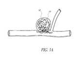
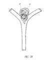
- the aneurysms 10 , 20may be difficult to treat with embolization coils alone because the coils may be prone to herniating into parent vessels, as illustrated in FIGS. 3A and 3B .
- Herniation of coilsmay cause arterial occlusion, stroke, and/or death.
- the efferent vessels of the bifurcationmay be at substantially different angles, have substantially different sizes, and/or be a different quantity (e.g., three or more).
- a different quantitye.g., three or more
- the aneurysm 20 of the bifurcationmay be offset with respect to the junction (e.g., having a neck substantially open to one efferent vessel), tilted with respect to a plane created by the vessels (e.g., into or out of the page), etc.
- the junctione.g., having a neck substantially open to one efferent vessel
- tilted with respect to a plane created by the vesselse.g., into or out of the page
- tubular neck remodeling devicesfor example NeuroformTM, available from Boston Scientific, and EnterpriseTM, available from Cordis Neurovascular, may be used to keep coils or other materials within the fundus of the aneurysm and out of the vessels.
- Tubular remodeling devicesgenerally consist of a braided wire or cut metallic stent or stents covering the neck of the aneurysm so that materials introduced into the fundus of the aneurysm do not herniate out of the aneurysm.
- tubular remodeling devices 40are generally useful for side wall aneurysms 10 .
- tubular remodeling devices 42 , 44are generally less useful for aneurysms 20 at bifurcations, for example because shaping the remodeling devices to preserve blood flow through the afferent and efferent vessels while also inhibiting herniation of coils 28 out of the aneurysm 20 can be difficult.
- Another current method used to inhibit herniation of embolization coils used to treat bifurcation aneurysmsis balloon-assisted remodeling.
- a balloonis inflated at the bifurcation during the embolization process.
- the inflated ballooncovers the neck of the aneurysm, inhibiting coils from herniating out of the aneurysm.
- an intraluminal apparatusincluding a catheter and a vascular remodeling device.
- the deviceis positionable at a junction of afferent and efferent vessels of a bifurcation (e.g., a neurovascular bifurcation) having an aneurysm having a fundus and a neck.
- Positioningmay comprise deployment from a compressed state at least partially inside a catheter to outside the catheter.
- Positioningmay comprise reshaping the device by using a filament (e.g., a central filament) coupled to an end of the device to adjust the distance between the proximal and distal ends and locking the reshaped device into shape.
- a filamente.g., a central filament
- the devicemay be retracted into the catheter and then redeployed to achieve different shape or positioning. During deployment, the device may self-expand to conform to the junction. The device may lock into place across the arterial ostia and the neck of the aneurysm. Once the device is positioned at the junction, it may be optionally mechanically, electrolytically, or chemically released from the catheter. After positioning the device at the junction, the device acts as a scaffolding to inhibit or prevent herniation or prolapse of objects such as embolization coils and thrombi out of the neck of the aneurysm. Embolic material may be inserted in the fundus of the aneurysm before or after positioning the device, and before or after optional release of the device from the catheter.
- the deviceAfter positioning the device at the junction, the device permits perfusion of fluid (e.g., blood) to the efferent vessels.
- the devicemay then be retracted into the catheter and withdrawn from the vasculature.
- the devicemay have a proximal end, a distal end, and a plurality of filaments extending between and coupled at the proximal end and at the distal end.
- Certain such devicesmay be football shaped, pumpkin shaped, twisted, or acorn shaped.
- the filamentsmay comprise materials such as Nitinol, MP35N®, or L605.
- the filamentsmay comprise a self-expanding and/or a shape-memory material (e.g., comprising CoCr alloy, etc.).
- the filamentsmay comprise a variety of dimensions and geometries (e.g., round, flat, etc.) and may comprise individual wires (e.g., round wires or flat ribbons) or be cut from a tube or a sheet, which are heat set to an expanded position.
- the composition, quantity, and dimensions of the filamentsmay be related to the conformability of the device at the junction of a bifurcation.
- An acorn-shaped devicemay comprise a distal section of the plurality of filaments that comprises a feature (e.g., a leaf-shaped feature) configured to increase the surface area of the distal section.
- the devicemay comprise a distal section of the plurality of filaments that spirals towards the distal end of the device.
- Distal ends of the filamentsmay comprise a coating configured to preferentially repel certain material (e.g., liquid embolic material).
- the devicemay comprise a filament (e.g., a central filament) that can be used to reshape the device by adjusting a distance between the proximal and distal ends of the device.
- the devicemay be locked into its reshaped deployed state (e.g., using a ring proximate to an end of the device that catches on prongs located on the central filament).
- the distal end of the devicemay comprise a covering configured to inhibit herniation of embolic material out of the neck of the aneurysm.
- the coveringmay comprise materials such as polyester, nylon, polytetraflueoroethylene, polyglactic acid, and polyglycolic acid.
- Radiopaque markersmay be placed at one or both ends of the device and/or at least one of the filaments may comprise a radiopaque material (e.g., platinum).
- a method of treating an aneurysmis provided.
- the aneurysmis at a junction of a bifurcation having an afferent vessel and efferent vessels.
- the aneurysmhas a neck and a fundus.
- the methodcomprises advancing a catheter proximate to the junction of the bifurcation.
- the catheterat least partially contains a device in a compressed state.
- the devicecomprises a plurality of filaments extending between the proximal end and the distal end and coupled at the proximal end and at the distal end.
- the methodfurther comprises deploying the device from at least partially inside the catheter to outside the catheter at the junction of the bifurcation.
- the deviceself-expands to conform in an expanded state to the junction of the bifurcation.
- the deviceacts as a scaffolding to inhibit herniation of objects out of the neck of the aneurysm and permits perfusion of fluid to the efferent vessels.
- the methodfurther comprises retracting the device at least partially back inside the catheter and withdrawing the catheter and the device.
- an intraluminal apparatuscomprises a catheter and a device.
- the devicehas a distal end and a proximal end and comprises a plurality of filaments extending between the proximal end and the distal end and coupled at the proximal end and at the distal end.
- the deviceis configured to self-expand from a compressed state upon deployment from at least partially inside the catheter to outside the catheter to conform in an expanded state to a junction of a bifurcation.
- the bifurcationhas an afferent vessel, efferent vessels, and an aneurysm having a neck and a fundus.
- the deviceis configured to act as a scaffolding to inhibit herniation of objects out of the neck of the aneurysm and to permit perfusion of fluid to the efferent vessels while the proximal end of the device is connected to the catheter.
- the deviceis retractable from the expanded state at least partially back inside the catheter.
- an intraluminal apparatuscomprising a catheter and a device having a distal end and a proximal end.
- the deviceis configured to self-expand upon deployment from at least partially inside the catheter to outside the catheter.
- the deviceis configured to conform in an expanded state to a junction of a bifurcation having an afferent vessel, efferent vessels, and an aneurysm having a neck and a fundus.
- the distal end of the devicecomprises a covering configured to act as a scaffolding to inhibit herniation of embolic material out of the neck of the aneurysm.
- the deviceis configured to permit perfusion of fluid to the efferent vessels.
- a method of treating an aneurysm at a junction of a bifurcationcomprises advancing a catheter proximate to the junction of the bifurcation.
- the catheterat least partially contains a device in a compressed state.
- the devicecomprises a plurality of filaments and a central filament.
- the methodfurther comprises deploying the device from at least partially inside the catheter to outside the catheter at the junction of the bifurcation. During deployment, the device self-expands to conform to the junction of the bifurcation.
- the methodfurther comprises reshaping the deployed device by using the central filament to adjust a distance between a proximal end of the device and a distal end of the device.
- the deviceacts as a scaffolding to inhibit herniation of objects out of the neck of the aneurysm and permits perfusion of fluid to the efferent vessels.
- the methodfurther comprises retracting the device at least partially back inside the catheter and withdrawing the catheter and the device.
- an intraluminal apparatuscomprises a catheter and a device having a proximal end connected to the catheter and a distal end.
- the devicecomprises a plurality of filaments extending between the proximal end and the distal end and coupled at the proximal end and at the distal end.
- the filamentsare configured to self-expand upon deployment from inside the catheter to outside the catheter.
- the filamentsare configured to conform in an expanded state to a junction having an afferent vessel, efferent vessels, and an aneurysm having a neck and a fundus.
- the devicefurther comprises a central filament extending between the proximal end and the distal end.
- the central filamentis configured to reshape the device in the expanded state by adjusting a distance between the distal end and the proximal end.
- the deviceis configured to act as a scaffolding to inhibit herniation of objects out of the neck of the aneurysm and to permit perfusion of fluid to the efferent vessels while the proximal end of the device is connected to the catheter.
- FIG. 1illustrates an example embodiment of a side wall aneurysm.
- FIG. 2illustrates an example embodiment of a bifurcation having an aneurysm.
- FIG. 3Aillustrates an example embodiment of a side wall aneurysm with herniating embolization coils.
- FIG. 3Billustrates an example embodiment of a bifurcation having an aneurysm with herniating embolization coils.
- FIG. 4Aillustrates an example embodiment of a side wall aneurysm treated with embolization coils and a tubular remodeling device.
- FIGS. 4B and 4Cillustrates example embodiments of a bifurcation having an aneurysm treated with embolization coils and tubular remodeling devices.
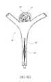
- FIG. 5illustrates an example embodiment of a vascular remodeling device.
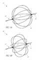
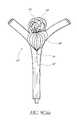
- FIGS. 6A and 6Billustrate another example embodiment of a vascular remodeling device.
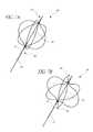
- FIGS. 7A and 7Billustrate an example embodiment of reshaping the device of FIGS. 6A and 6B .
- FIGS. 8A and 8Billustrate an example embodiment of another vascular remodeling device.
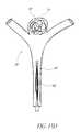
- FIGS. 9A - 9 Ciibillustrate example embodiments of methods for treating an aneurysm using the device of FIG. 5 .
- FIGS. 10A and 10Billustrate an example embodiment of a mechanical release mechanism.
- FIGS. 11A-11Dillustrate other example embodiments of mechanical release mechanisms.
- FIGS. 12A and 12Billustrate an example embodiment of a mechanism for releasing and reshaping the device.
- FIGS. 13A-13Dillustrate another example embodiment of a method for treating an aneurysm using the device of FIG. 5 .
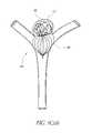
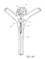
- FIG. 14illustrates another example embodiment of a vascular remodeling device.
- FIG. 15illustrates another example embodiment of a vascular remodeling device.
- FIG. 16Aillustrates a side elevational view of another example embodiment of a vascular remodeling device.
- FIG. 16Billustrates a top perspective view of the device of FIG. 16A .
- FIG. 16Cillustrates a top plan view of the device of FIG. 15A .
- FIG. 17Aillustrates a top perspective view of another example embodiment of a vascular remodeling device.
- FIG. 17Billustrates a top plan view of the device of FIG. 17A .
- FIG. 18Aillustrates a top perspective view of another example embodiment of a vascular remodeling device.
- FIG. 18Billustrates a top plan view of the device of FIG. 18A .
- FIG. 19Aillustrates a top perspective view of another example embodiment of a vascular remodeling device.
- FIG. 19Billustrates a top plan view of the device of FIG. 19A .
- FIGS. 20A-20Dillustrate an example embodiment of a method for treating an aneurysm using the device of FIG. 15A .
- FIG. 21illustrates an example embodiment of a vascular remodeling device at a stage of an example manufacturing process.
- FIG. 5illustrates an example embodiment of a generally spherical vascular remodeling device 80 .
- the device 80may be more compliant than the vasculature in which it is deployed such that it may be somewhat misshapen (e.g., non-spherical, for example as illustrated in FIG. 9B ) after being deployed, and that the phrase “generally spherical” describes the shape of the device 80 when in an expanded (e.g., fully expanded) state outside of vasculature. Additionally, the phrase “generally spherical” distinguishes the device 80 , which is generally uniform in each dimension in an expanded state, from tubular devices having a small radial dimension and a large longitudinal dimension in an expanded state.
- an outer periphery of the devicehas a shape that deviates by between about 10% and about 25% from an outer periphery of a mathematically perfect sphere.
- the device 80has a length and a width that are within less than about 33% of each other (e.g., having a length of 6 mm and a width of 8 mm, having a length of 6 mm and a width of 8 mm).
- the widthis greater than the length may be advantageous due to a difference in porosity at a midpoint and an end proximate to an aneurysm.
- Embodiments in which the length is greater than the widthmay be advantageous for positioning a portion of the device 80 in a portion of the aneurysm 20 (e.g., to aid in embolization).
- the device 80comprises a first or distal end 81 and a second or proximal end 82 substantially opposite the first end 81 .
- the device 80further comprises a plurality of filaments 84 extending between the distal end 81 and the proximal end 82 .
- the distal end 81extends outwardly and the proximal end 82 extends outwardly to form a generally spherical (e.g., oval or oblong) shape similar to a football, a rugby ball, or a watermelon.
- the filaments 84are coupled at the distal end 81 and/or the proximal end 82 (e.g., by adhering, welding, soldering, combinations thereof, and the like).
- the device 80is connected to a catheter (e.g., the catheter 92 described herein) at the proximal end 82 of the device 80 .
- the device 80comprises a lead or tail 83 , which may be used for releasing and/or retracting the device 80 after deployment, as described herein.
- the device 80is connected to a catheter (e.g., the catheter 92 described herein) at the lead or tail 83 of the device 80 .
- the device 80comprises a cut metallic sphere, a single filament (e.g., wrapped back and forth between the first and second ends), etc.
- the device 80is configured to be positioned at a junction of a bifurcation (e.g., a neurovascular bifurcation) comprising at least one afferent vessel, efferent vessels, and an aneurysm 20 having a fundus and a neck.
- a bifurcatione.g., a neurovascular bifurcation
- the device 80is suitably dimensioned to fit in a junction of a bifurcation (e.g., having a diameter between about 2 mm and about 12 mm, having a diameter between about 6 mm and about 8 mm, having a diameter less than about 12 mm, having a diameter greater than about 2 mm).
- the device 80is less rigid than a junction of a bifurcation (e.g., due to the number of filaments 84 , the material of the filaments 84 , the thickness of the filaments 84 , the spacing of the filaments 84 , the shape of the filaments 84 , combinations thereof, and the like).
- the device 80is configured to act as a scaffolding to inhibit or prevent herniation or prolapse of objects (e.g., embolization coils, embolic fluid, thrombi, etc.) out of a neck of an aneurysm 20 .
- the filaments 84are dense enough at or proximate to the neck of the aneurysm 20 that objects generally cannot pass.
- the device 80is configured to permit perfusion of fluid (e.g., blood) to efferent vessels of a bifurcation.
- At least one of the filaments 84comprises a self-expanding and/or a shape-memory material (e.g., comprising Nitinol, CoCr alloy, MP35N®, L605, etc.), thereby causing the device 80 to be self-expanding under certain conditions (e.g., not restrained by a catheter).
- at least one of the filaments 84comprises a different material than others of the filaments 84 (e.g., some filaments 84 comprising Nitinol and some filaments 84 comprising Nitinol and platinum).
- at least one of the filaments 84comprises a radiopaque material (e.g., platinum).
- an even number of filaments 84comprises a radiopaque material (e.g., platinum).
- at least one of the filaments 84comprises a radiopaque material (e.g., platinum) at least partially wrapped (e.g., coiled) around a self-expanding material (e.g., Nitinol).
- at least one of the filaments 84comprises a self-expanding material with a radiopaque core (e.g., Nitinol with a platinum core) or a radiopaque coating (e.g., Nitinol coated with platinum, tantalum, etc.
- the filaments 84have a substantially circular or ovoid cross section (e.g., embodiments, in which the filaments 84 comprise separate wires). In some embodiments, the filaments 84 have a substantially rectangular or flat cross section (e.g., embodiments, in which the filaments 84 comprise uncut portions of a metallic tube, as described below, or ribbons). Other shapes of filaments 84 and combinations of shapes of filaments 84 are also possible.
- the plurality of filaments 84comprises between about six and about twelve filaments 84 . In certain embodiments, the plurality of filaments 84 comprises at least about six filaments 84 , at least about eight filaments 84 , or at least about twelve filaments 84 . Other numbers of filaments 84 are also possible.
- the device 80comprises a plurality of perforations or cells 86 between the filaments 84 .
- a percentage of the outer surface of the device 80 or a portion thereof (e.g., approximately at the line B-B in FIG. 5 ) covered by the filaments 84is greater than or equal to about 3%.
- a percentage of the outer surface of the device 80 or a portion thereof (e.g., approximately at the line B-B in FIG. 5 ) covered by the filaments 84is between about 3% and about 15% (e.g., about 5%).
- a percentage of the outer surface of the device 80 or a portion thereof (e.g., approximately at the line B-B in FIG. 5 ) covered by the cells 86is less than or equal to about 97%. In some embodiments, a percentage of the outer surface of the device 80 or a portion thereof (e.g., approximately at the line B-B in FIG. 5 ) covered by the cells 86 is between about 85% and about 97% (e.g., about 95%). In some embodiments, a percentage of the outer surface of the device 80 or a portion thereof (e.g., approximately at the line B-B in FIG.
- a percentage of the outer surface of the device 80 or a portion thereof (e.g., approximately at the line B-B in FIG. 5 ) covered by the filaments 84is between about 25% and about 40%. In certain embodiments, a percentage of the outer surface of the device 80 or a portion thereof (e.g., approximately at the line B-B in FIG. 5 ) covered by the cells 86 is between about 60% and about 75%. Other porosities are also possible. In some embodiments, porosity distally increases between the proximal end 82 and an approximate midpoint (e.g., approximately at the line A-A in FIG.
- cross-sections taken along the lines A-A and B-B in FIG. 5each have the same number of filaments 84 , but at the cross-section A-A the filaments 84 are spaced further apart from each other than at the cross-section B-B.
- the porosity at the cross-section A-Awould be about 80% with an example circumference of about 25 mm: 100% ⁇ [1 ⁇ ( ⁇ 0.5 mm/filament ⁇ 10 filaments/ ⁇ 25 mm)] ⁇ 80% and the porosity at the cross-section B-B would be about 33% with an example circumference of about 7.5 mm: 100% ⁇ [1 ⁇ ( ⁇ 0.5 mm/filament ⁇ 10 filaments/ ⁇ 7.5 mm)] ⁇ 33%.
- High porosity proximate to a midpoint of the device 80may provide good fluid flow to efferent vessels.
- Low porosity proximate to the distal end 81 of the device 80may provide good scaffolding properties.
- the device 80comprises a radiopaque marker 88 proximate to the distal end 81 and/or a radiopaque marker 89 proximate to the proximal end 82 .
- the radiopaque marker 88may extend at least partially into the aneurysm 20 when the device 80 is positioned at the junction of a bifurcation.
- the radiopaque markers 88 , 89may comprise a sleeve positioned or wrapped around the filaments 84 , thereby coupling the filaments 84 . The radiopaque markers 88 , 89 may aid in positioning the device 80 at the junction of a bifurcation.
- the device 80is configured to be highly conformable to the junction of a bifurcation (e.g., a neurovascular bifurcation) comprising at least one afferent vessel, efferent vessels, and an aneurysm 20 having a fundus and a neck.
- a bifurcatione.g., a neurovascular bifurcation
- the remodeling device 80comprises filaments 84 comprising a material and having a thickness and cross-sectional shape that conforms to and allows good compliance with the vasculature at the junction of the bifurcation.
- At least one filament 84 of the plurality of filaments 84comprises a round wire (e.g., having a circular cross-section).
- the round wirehas a diameter between about 0.002′′ (approx. 0.05 mm) and about 0.006′′ (approx. 0.15 mm), between about 0.0025′′ (approx. 0.05 mm) and about 0.004′′ (approx. 0.10 mm), or between about 0.003′′ (approx. 0.08 mm) and about 0.0037′′ (approx. 0.09 mm).
- the round wirecomprises an outer sheath comprising a first material and an inner core comprising a second material (e.g., comprising platinum, platinum-tungsten, tantalum, silver, or gold).
- the second material of the inner coreis radiopaque.
- at least one filament 84comprises a thin wire coiled around a round wire.
- the thin wirehas a diameter between about 0.009′′ (approx. 0.023 mm) and about 0.002′′ (approx. 0.051 mm), between about 0.001′′ (approx. 0.025 mm) and about 0.0175′′ (approx. 0.044 mm), or between about 0.00125′′ (approx.
- the thin wirecomprises platinum, platinum-tungsten, tantalum, silver, or gold. In some embodiments, the thin wire comprises a radiopaque material.
- At least one filament 84 of the plurality of filaments 84comprises a flat wire or ribbon (e.g., having a rectangular cross-section).
- the flat wirehas a thickness between about 0.001′′ (approx. 0.0025 mm) and about 0.003′′ (approx. 0.076 mm) and a width between about 0.003′′ and about 0.005′′, a thickness between about 0.0015′′ (approx. 0.0381 mm) and about 0.0025′′ (approx. 0.064 mm) and a width between about 0.0035′′ (approx. 0.089 mm) and about 0.0045′′ (approx. 0.114 mm), or a thickness between about 0.00175′′ (approx. 0.044 mm) and about 0.00225′′ (approx. 0.057 mm) and a width between about 0.00375′′ (approx. 0.095 mm) and about 0.00425′′ (approx. 0.108 mm).
- the device 80comprises between about 4 filaments 84 and about 12 filaments 84 or between about 6 filaments 84 and about 12 filaments 84 .
- Other numbers of filaments 84are also possible.
- combinations of different filaments 84are used in the same device 80 (e.g., 6 filaments comprising Nitinol and 2 round filaments comprising Nitinol and having a thin platinum wire coiled around the two round filaments).
- FIGS. 6A and 6Billustrate an example embodiment of a generally spherical vascular remodeling device 85 that is reshapable.
- the device 85comprises a plurality of filaments 84 extending between the second or proximal end 82 and the first or distal end 81 and coupled at the proximal 82 and distal ends 81 and defining a generally spherical shape.
- the device 85 and the filaments 84are configured to conform to a junction of a bifurcation having an afferent vessel, efferent vessels, and an aneurysm 20 having a neck and a fundus.
- the device 85may be used during treatment of the aneurysm 20 to act as a scaffolding to inhibit herniation of objects out of the neck of the aneurysm 20 and to permit perfusion of fluid to the efferent vessels.
- the device 85comprises a central filament 91 extending between the proximal end 82 and the distal end 81 .
- the central filament 91is configured to reshape the device 85 while the device 85 is in an expanded state.
- the central filament 91is rigid (e.g., having a size and/or shape configured to allow pushing and pulling without significant deformation of the central filament).
- the central filament 91can reshape the device 85 by adjusting the distance between the distal end 81 and the proximal end 82 .
- pulling the central filament 91e.g., by manipulating the central filament 91 by action on a proximal portion of the central filament 91 or a mechanism coupled thereto
- the distal end 81can pull the distal end 81 towards the proximal end 82 (e.g., because the proximal end 82 abuts a catheter and/or the ostium of the afferent vessel), thereby squeezing the ends 81 , 82 of the device 85 together and changing the shape of the device 85 , for example causing radial bulging as depicted in FIG.
- pushing the central filament 91e.g., by manipulating the central filament 91 by action on a proximal portion of the central filament 91 or a mechanism coupled thereto
- pushing the central filament 91can push the distal end 81 away from the proximal end 82 , thereby lengthening the device 85 and changing the shape of the device 85 .
- the central filament 91may act as a guide for reshaping the device 85 .
- the proximal end 82may be pushed along the central filament 91 towards the distal end 81 (e.g., because the distal end 81 abuts the neck of the aneurysm), thereby squeezing the ends 81 , 82 of the device 85 together and changing the shape of the device 85 .
- the proximal end 82may be pulled along the central filament 91 away from the distal end 81 , thereby lengthening the device 85 and changing the shape of the device 85 .
- a filament that can be used to reshape the device 85may be coupled to the proximal end 82 and does not extend through the device 85 .
- pushing the filamente.g., by manipulating the filament by action on a proximal portion of the filament or a mechanism coupled thereto
- pushing the filamentcan push the proximal end 82 towards the distal end 81 , thereby squeezing the ends 81 , 82 of the device 85 together and changing the shape of the device 85 , for example causing radial bulging.
- pulling the filamente.g., by manipulating the filament by action on a proximal portion of the filament or a mechanism coupled thereto
- pulling the filamentcan pull the proximal end 82 away from the distal end 81 , thereby lengthening the device 85 and changing the shape of the device 85 .
- FIGS. 7A and 713illustrate an example embodiment of a device 85 comprising a central filament 91 , prongs 73 , and a ring 71 proximate to the proximal end 82 .
- the ring 71is configured to slice past the prongs 73 as the ring 71 is advanced distally, but to catch on the prongs 73 as the ring 71 is advanced proximally.
- FIG. 7Bdepicts the device 85 after the proximal end 82 has been pushed towards the distal end 81 , shortening the device 85 .
- the ring 71is configured to slide past the prongs 73 as the ring 71 is advanced proximally, but to catch on the prongs 73 as the ring 71 is advanced distally, lengthening the device 85 .
- the ring 73may be configured to be capable of sliding past the prongs 73 in both the distal and proximal direction, but to catch on the prongs 73 to maintain the reshaped state.
- the reshaping capability of the device 85may advantageously allow the device 85 to be conformable to a junction of a bifurcation. Although illustrated and described as a “central” filament, other arrangements of one or more filaments or other mechanisms may be used to reshape a deployed device.
- FIGS. 8A and 8Billustrate example embodiments of generally spherical remodeling device 70 .
- the device 70has a proximal end 82 and a distal end 81 .
- the device 70comprises a plurality of filaments 84 extending between the proximal end 82 and the distal end 81 .
- the device 70comprises a covering 93 (e.g., comprising a porous, semi-porous (e.g., as depicted in FIG. 8A ), or non-porous (e.g., as depicted in FIG. 8B ) material) coupled or attached to the distal end 81 .
- the covering 93is configured to act as a scaffolding to inhibit herniation of objects out of the neck of the aneurysm 20 .
- the covering 92is configured to act as a scaffolding to inhibit herniation of embolic material out of the neck of the aneurysm 20 .
- the device 70is configured to conform to a junction of a bifurcation having an afferent vessel, efferent vessels, and an aneurysm 20 having a neck and a fundus.
- the device 70is configured to permit perfusion of fluid to the efferent vessels.
- a cathetermay be used to deliver the device 70 in a collapsed state to a location in the vasculature.
- the covering 93comprises a polymer (e.g., polyester, nylon, polytetrafluoroethylene (PTFE), combinations thereof, and the like).
- the covering 93comprises a bio-absorbable polymer (e.g., polylactic acid (PLA), polyglycolic acid (PGA), combinations thereof, and the like). Other polymers and materials are possible.
- the covering 93may have varying levels of porosity.
- the covering 93comprises a few polymer filaments sewn together, creating a very porous covering 93 .
- the covering 93comprises a semi-porous material (e.g., as depicted in FIG. 8A ).
- the covering 93may comprise braided polymer filaments or a perforated polymer sheet.
- the covering 93comprises a virtually non-porous material (e.g., as depicted in FIG. 8B ).
- attaching the covering 93 to the device 70comprises sewing the covering 93 from a pre-formed thin film.
- attaching the covering 93 to the device 70comprises mechanical attachment (e.g., wrapped around, looped through, etc.) to the filaments 84 .
- attaching the covering 93 to the device 70comprises depositing (e.g., via physical vapor deposition, chemical vapor deposition, etc.) the covering 93 on the filaments 84 .
- Other portions of the device 70may also comprise a covering as long as flow between the afferent vessel and the efferent vessels is maintained.
- attaching the covering 93 to the device 70comprises forming polymer whiskers on the distal ends of the filaments 84 .
- forming the polymer whiskerscomprises chemically treating the distal ends of the filaments 84 .
- the whiskersmay be sown, chemically treated, mechanically attached, or coupled in another manner in order to form a porous, semi-porous, or non-porous covering 93 .
- the covering 93 and the plurality of filaments 84together act as a scaffolding to inhibit herniation of objects out of the neck of the aneurysm 20 by reducing the porosity at the distal end 81 , thereby further inhibiting or preventing the herniation or prolapse of embolic material from the aneurysm 20 .
- a device 70 comprising a covering 93 on at least a portion of the device 70can allow the device 70 to comprise fewer filaments 84 .
- the covering 93may alone provide suitable scaffolding properties, and the filaments 84 do not need to provide scaffolding properties, thereby allowing the device 70 to comprise fewer filaments 84 .
- a reduced number of filaments 84may decrease material and manufacturing costs associated with the device 70 , for example because the device 70 uses less filament material.
- a reduced number of filamentsmay increase the conformability of the device 70 because fewer filaments 84 contain fewer nodes where the filaments 84 contact the vasculature, which can allow for greater flexibility and conformability to the junction of a bifurcation 60 containing an aneurysm 20 .
- a reduced number of filamentscan allow the device 70 to be more collapsible and more easily manipulated within the vasculature and delivered to the treatment site.
- a remodeling device comprising filaments 84 such as certain embodiments described hereinmay possess greater conformability at the junction of a bifurcation 60 than balloon remodeling devices, for example those described in U.S. patent application Ser. No. 10/235,064, filed Sep. 4, 2002, and U.S. patent application Ser. No. 11/868,049, filed Oct. 5, 2007, each of which are incorporated herein by reference in its entirety.
- This greater conformabilitymay occur because a balloon has a continuous surface that generally wholly conforms to a junction, whereas the remodeling devices described herein can conform to the junction only where the filaments 84 contact the vasculature.
- a remodeling devicecomprising filaments 84 such as certain embodiments described herein may reduce damage to vasculature by permitting blood to flow to efferent vessels of a bifurcation 60 throughout a treatment process after a single deployment from a catheter, whereas balloon remodeling devices generally occlude flow to the efferent vessels such that the balloon is periodically deflated in order to restore perfusion, and such repeated inflation and deflation may damage the vasculature.
- the distal ends of the filaments 84 and/or a covering 93may comprise a coating configured to preferentially repel certain material.
- the coatingmay be configured to preferentially repel liquid embolic material (e.g., Onyx®).
- forming such a coating on the distal ends of the filaments 84comprises chemically treating the filaments 84 . Certain such coatings may allow delivery of liquid embolic material through the device 80 while inhibiting, reducing, or preventing permeation of the liquid embolic material from out of the aneurysm through the device 80 .
- FIGS. 9A - 9 Ciibillustrate an example embodiment of a method for treating an aneurysm 20 using an apparatus comprising the device 80 and a catheter 92 .
- FIG. 9Aillustrates a confluence of afferent and efferent vessels or “junction” at a bifurcation 60 having an aneurysm 20 .
- the vasculatureis neurovascular or cranial.
- the aneurysm 20may be treated by inserting material (e.g., embolic coils, embolic liquid) into the aneurysm 20 .
- the aneurysm 20is illustrated with a plurality of embolization coils 62 having been inserted in the fundus of the aneurysm 20 .
- the embolization coils 62may be a single embolization coil or other embolic material (e.g., Onyx® liquid embolic material).
- a catheter 92e.g., a microcatheter
- the catheter 92is small enough and flexible enough to be routed through the vasculature and situated proximate to the aneurysm 20 (e.g., as depicted in FIG. 9A ).
- the embolization coils 62are inserted in the fundus of the aneurysm 20 using the catheter 92 .
- the embolization coils 62are inserted in the fundus of the aneurysm 20 using a different catheter.
- a guidewiremay be used to guide both catheters.
- FIG. 9Billustrates the bifurcation 60 after the device 80 has been deployed from the catheter 92 (e.g., by being pushed out with a plunger, by retracting the catheter 92 while the device 80 remains stationary, combinations thereof, and the like) at the junction of the bifurcation 60 .
- the device 80may expand.
- the device 80comprises a self-expanding and/or a shape-memory material that automatically expands towards an uncompressed state or expands towards an uncompressed state upon the application of warm fluid (e.g., saline).
- warm fluide.g., saline
- the device 80expands upon being forced radially outwardly by a balloon upon inflation. Other expansion mechanisms are also possible.
- the device 80may substantially conform to the shape of the junction of the bifurcation 60 (e.g., not substantially including portions extending into the afferent and efferent vessels) and locks into place across the ostia of the afferent and efferent vessels and the neck of the aneurysm 20 .
- the device 80at least partially covers the neck of the aneurysm 20 as well as the afferent and efferent vessels, but does not need to divert flow.
- the device 80acts as a scaffolding to inhibit or prevent herniation or prolapse of objects such as the embolization coils 62 and/or thrombi out of the aneurysm 20 .
- the device 80also allows perfusion of fluid (e.g., blood) from the afferent vessel(s) to the efferent vessel(s).
- the devicemay be optionally reshaped after it has been deployed from the catheter 92 and is in an expanded state, for example to conform to the shape of the junction of the bifurcation 60 or to better conform to the shape of the junction of the bifurcation 60 .
- the devicemay be reshaped by advancing or retracting the proximal end 82 of the device along a central filament 91 and using a locking mechanism 71 , 73 to lock the device in the reshaped state.
- FIG. 9Ciillustrates an embodiment in which the device 80 is withdrawn from the vasculature after the device 80 has been retracted into the catheter 92 .
- the device 80performs a function (e.g., inhibiting herniation of objects from the neck of the aneurysm 20 ) in a deployed state while connected to the catheter 92 , the device 80 is retracted into the catheter 92 and the entire apparatus is withdrawn from the vasculature.
- a functione.g., inhibiting herniation of objects from the neck of the aneurysm 20
- the device 80may be retracted into the catheter 92 after being deployed from the catheter 92 (e.g., by pulling on a tail). The device 80 may then be redeployed, for example at a new angle, at a new rotational position) more proximal or distal to an afferent vessel and/or an efferent vessel, etc.
- the resulting shape of the device 80 at the junction of the bifurcation 60may vary depending on the details of the deployment from the catheter 92 because the device 80 adapts to the shape of the anatomy (e.g., due to the size, shape, number, etc. of the filaments 84 ).
- the device 80may optionally be released as described herein.
- FIGS. 9 Ciia and 9 Ciibdepict an optional embodiment in which the device 80 is released from the catheter 92 after the deployment illustrated in FIG. 9B or after redeployment.
- FIG. 9 Ciiaillustrates releasing the device 80 from the catheter 92 (e.g., by a mechanical, chemical, or electrolytic release mechanism) at a release point 95 .
- FIG. 9 Ciibillustrates the device 80 remaining in position at the junction of the bifurcation 60 after the catheter 92 has been withdrawn from the vasculature.
- the devices described hereinmay be used in any of the methods described herein (e.g., the method described with respect to FIGS. 9Ci - 9 Ciib, the methods described with respect to FIGS. 12A-12D , the methods described the methods described with respect to FIGS. 19A-19D ), combinations of the same, or the like.
- FIGS. 10A and 10Billustrate a device 100 comprising an example embodiment of a release mechanism 102 .
- the release mechanism 102comprises a wire 72 , hooks 74 , 78 , and a sleeve 76 .
- the wire 72extends between the proximal end 82 and the distal end 81 (e.g., through the center of the device 100 ).
- the wire 72may be the same as the central filament 91 described with respect to the device 85 herein, and it may be possible to change and lock the shape of the device 100 .
- the proximal end of the wire 72comprises the hook 74 .
- the distal end of the cathetercomprises (e.g., is integrally part of, is connected to, etc.) the hook 78 .
- FIG. 10Billustrates the device 100 after retracting the sleeve 76 (e.g., by retracting the wire 72 ) to expose the hooks 74 , 78 , which allows the hook 74 to disconnect from the hook 78 , thereby mechanically releasing the device 100 from the catheter.
- the device 100is mechanically released from the catheter, or a component of the catheter, by disconnecting an interlock holding the catheter to a wire of the device 100 (e.g., a tail).
- the interlockcomprises a keyway, for example as described in International Application No. PCT/US2007/066722, which is incorporated herein by reference in its entirety, and the device 100 may be optionally released from the catheter, or a component connected to the catheter, by manipulating the keyway.
- FIG. 11Aillustrates an example embodiment of a keyway 104 .
- the keyway 104comprises a male end 106 and a female end 108 .
- the device 100may be optionally released from the catheter, or a component connected to the catheter, by manipulating the male and female ends 106 , 108 and separating them.
- the male end 106is selectively slidable out of the female end 108 .
- the male and female ends 106 , 108are confined within a sleeve. Upon removal from the sleeve, the male and female ends 106 , 108 may be released from one another.
- the device 100may comprise the female end 108 and the catheter may comprise the male end 106 .
- the cathetermay comprise (e.g., is integrally part of, is connected to, etc.) the female end 108 and the device 100 may comprise the male end 106 .
- FIG. 11Billustrates an example embodiment of a release mechanism 120 comprising a plurality of puzzle pieces 122 , 124 .
- the device 100may be optionally released from the catheter, or a component connected to the catheter, by manipulating the puzzle pieces 122 , 124 and separating them.
- the puzzle pieces 122 , 124are confined within a sleeve. Upon removal from the sleeve, the puzzle pieces 122 , 124 may be released from one another.
- FIGS. 11C and 11Dillustrate an example embodiment of a release mechanism comprising a pop out mechanism 126 .
- the pop out mechanism 126comprises a sleeve 75 , arms 77 , and a bulbous portion 79 .
- the devicemay be optionally released from the catheter, or a component connected to the catheter, by manipulating the sleeve 75 .
- the arms 77are held in place around the bulbous portion 79 .
- the arms 77are able to expand (e.g., due to self-expanding properties, due to being easily moved by ambient forces, being moved by opposing force of the bulbous portion 79 , etc.) and the arms 77 no longer hold the bulbous portion 79 in place.
- the arms 77 and the bulbous portion 79may have any suitable shape.
- the arms 77 and/or the bulbous portion 79may include angled features to aid movement of the arms 77 upon application of an opposing force (e.g., acting as a plane to convert longitudinal movement into lateral movement).
- the devicee.g., a proximal end of the device, a filament of the device, a central filament of the device, etc.
- the devicecomprises (e.g., is integrally part of, is connected to, etc.) the arms 77 and the catheter comprises (e.g., is integrally part of, is connected to, etc.) the bulbous portion 79 .
- the device(e.g., a proximal end of the device, a filament of the device, a central filament of the device, etc.) comprises (e.g., is integrally part of, is connected to, etc.) the bulbous portion 79 and the catheter comprises (e.g., is integrally part of, is connected to, etc.) the arms 77 .
- FIGS. 12A and 12Bdepict an embodiment of the pop out mechanism 126 described herein, in which the mechanism 126 may be used to release a device 85 comprising a central filament 127 , for example as described with respect to FIGS. 6A and 6B .
- the pop out mechanism 126 and the central filament 127may be configured to release the device 85 from the catheter and to lock the device 85 in a reshaped state.
- the central filament 127comprises (e.g., is integrally part of, is connected to, etc.) a plurality of outwardly-biased arms 77
- the cathetercomprises (e.g., is integrally part of, is connected to, etc.) a bulbous portion 79
- the proximal end 128 of the device 85comprises a sleeve 75 .
- the sleeve 75is used to couple the filaments 84 (filaments 84 not shown in FIGS. 12A and 12B ) at the proximal end 128 of the device 85 .
- the central filament 127is slidable within the sleeve 75 .
- the central filament 127is only slidable within the sleeve 75 in one direction (e.g., proximally).
- the sleeve 75is configured to contain the plurality of arms 77 around the bulbous portion 79 when the central filament 127 is in a first position relative to the sleeve 75 (e.g., FIG. 12A ).
- the sleeve 75comprises a substantially uniform tube.
- the sleeve 75comprises a narrow side and an expanded side, for example to limit movement of the contained plurality of arms 77 and bulbous portion 79 (e.g., the narrow side preventing distal movement of the contained plurality of arms 77 and bulbous portion 79 ).
- the sleeve 75comprises a crimp, for example to limit movement of the contained plurality of arms 77 and bulbous portion 79 (e.g., the crimp preventing distal movement of the contained plurality of arms 77 and bulbous portion 79 ).
- the plurality of arms 77are each configured to outwardly expand (e.g., self-expand to an outwardly expanded state when not confined by the sleeve 75 as a result of being heat set in the outwardly expanded state) to lock into shape the reshaped deployed device 85 and to release the bulbous portion 79 when the central filament 127 is in a second position relative to the sleeve 75 (e.g., FIG. 12B ).
- the second positionis proximal to the first position.
- the central filament 127is pulled proximally to release the arms 77 from the sleeve 75 .
- the proximal end 128is pushed distally to release the arms 77 from the sleeve 75 .
- the plurality of arms 77are configured to catch on a proximal end of the sleeve 75 , holding the proximally-pulled central filament 127 in place and locking into place the reshaped device 85 .
- the further the second positionis from the first position, the shorter the distance between the proximal end and the distal end of the reshaped device 85 .
- all of the devices described hereinmay comprise any of the release mechanisms described herein (e.g., the release mechanisms described with respect to FIGS. 10A-12B , combinations of the same, and the like).
- the device 80may be optionally released from the catheter 92 electrolytically (e.g., by applying a small current until a portion of a tail proximal to the device 80 corrodes away, as illustrated by the gap 95 ).
- the catheter 92is then withdrawn from the bifurcation 60 , thereby leaving or permanently positioning the device 80 at the junction of the bifurcation 60 .
- the device 80is optionally released from the catheter 92 chemically (e.g., by dissolving a coating or segment with dimethyl sulfoxide (DMSO) (e.g., as illustrated by the gap 95 )).
- DMSOdimethyl sulfoxide
- FIGS. 13A-13Dillustrate another example embodiment of a method for treating an aneurysm 20 using an apparatus comprising the device 80 and a catheter 92 .
- FIG. 9Aillustrates a confluence of afferent and efferent vessels or “junction” at a bifurcation 60 having an aneurysm 20 .
- the vasculatureis neurovascular or cranial.
- the aneurysm 20may be treated by inserting material (e.g., embolic coils, embolic liquid) into the aneurysm 20 .
- a catheter 92e.g., a microcatheter
- the catheter 92is small enough and flexible enough to be routed through the vasculature and situated proximate to the aneurysm 20 (e.g., as depicted in FIG. 13A ).
- FIG. 13Billustrates the bifurcation 60 after the device 80 has been deployed from the catheter 92 (e.g., by being pushed out with a plunger, by retracting the catheter 92 while the device 80 remains stationary, combinations thereof, and the like) at the junction of the bifurcation 60 .
- the device 80may expand.
- the device 80comprises a self-expanding and/or a shape-memory material that automatically expands towards an uncompressed state or expands towards an uncompressed state upon the application of warm fluid (e.g., saline).
- warm fluide.g., saline
- the device 80expands upon being forced radially outwardly by a balloon upon inflation. Other expansion mechanisms are also possible.
- the device 80may substantially conform to the shape of the junction of the bifurcation 60 (e.g., not substantially including portions extending into the afferent and efferent vessels) and locks into place across the ostia of the afferent and efferent vessels and the neck of the aneurysm 20 .
- the device 80at least partially covers the neck of the aneurysm 20 as well as the afferent and efferent vessels, but does not need to divert flow.
- the device 80acts as a scaffolding to inhibit or prevent herniation or prolapse of objects such as thrombi out of the aneurysm 20 .
- the device 80allows perfusion of fluid (e.g., blood) from the afferent vessel(s) to the efferent vessel(s).
- the device 80may be retracted into the catheter 92 after being deployed from the catheter 92 (e.g., by pulling on a tail). The device 80 may then be redeployed, for example at a new angle, at a new rotational position, more proximal or distal to an afferent vessel and/or an efferent vessel, etc.
- the resulting shape of the device 80 at the junction of the bifurcation 60may vary depending on the details of the deployment from the catheter 92 because the device 80 adapts to the shape of the anatomy (e.g., due to the size, shape, number, etc. of the filaments 84 ).
- the device 80may optionally be released as described herein.
- FIG. 13Cillustrates the bifurcation 60 after a plurality of embolization coils 62 have been inserted in the fundus of the aneurysm 20 .
- the embolization coils 62may be a single embolization coil or other embolic material (e.g., Onyx® liquid embolic material).
- the embolization coils 62are inserted in the fundus of the aneurysm 20 using the catheter 92 .
- the embolization coils 62are inserted in the fundus of the aneurysm 20 using a different catheter.
- a guidewiremay be used to guide both catheters.
- the device 80acts as a scaffolding to inhibit or prevent herniation or prolapse of objects such as the embolization coils 62 and/or thrombi out of the aneurysm 20 .
- FIG. 13Dillustrates the bifurcation 60 after the catheter 92 and the device 80 have been removed.
- the device 80is connected to the catheter 92 for the total duration of the procedure.
- the embolization coils 62may be inserted in the fundus 22 of the aneurysm 20 after the device 80 has been deployed from the catheter 92 , but prior to withdrawal of the apparatus or optional release of the device 80 from the catheter 92 .
- the embolization coils 62may be inserted in the fundus of the aneurysm 20 after the device 80 has been deployed from the catheter 92 and after the device 80 has been optionally released from the catheter 92 .
- the embolization coils 62may be inserted into the fundus of the aneurysm 20 after the device 80 has been deployed from the catheter 92 (e.g., in a coil state), and the device 80 may be retracted and redeployed from the catheter 92 (e.g., in a final state).
- the devices described hereinmay be used in any of the methods described herein (e.g., the methods described with respect to FIGS. 9Ci - 9 Ciib, the methods described with respect to FIGS. 13A-13D , the methods described with respect to FIGS. 20A-20D ), combinations of the same, or the like.
- FIG. 14illustrates another example embodiment of a generally spherical vascular remodeling device 110 .
- the device 110may be more compliant than the vasculature in which it is deployed such that it may be somewhat misshapen (e.g., non-spherical) after being deployed, and that the phrase “generally spherical” describes the shape of the device 110 when in an expanded (e.g., fully expanded) state outside of vasculature. Additionally, the phrase “generally spherical” distinguishes the device 110 , which is generally uniform in each dimension in an expanded state, from tubular devices having a small radial dimension and a large longitudinal dimension in an expanded state.
- an outer periphery of the devicehas a shape that deviates by between about 10% and about 25% from an outer periphery of a mathematically perfect sphere.
- the device 110has a length and a width that are within less than about 33% of each other (e.g., having a length of 6 mm and a width of 8 mm, having a length of 6 mm and a width of 8 mm).
- the widthis greater than the length may be advantageous due to a difference in porosity at a midpoint and an end proximate to an aneurysm 20 .
- Embodiments in which the length is greater than the widthmay be advantageous for positioning a portion of the device 110 in a portion of the aneurysm 20 (e.g., to aid in embolization).
- the device 110comprises a first or distal end 111 and a second or proximal end 112 substantially opposite the distal end 111 .
- the device 110further comprises a plurality of filaments 114 extending between the distal end 111 and the proximal end 112 .
- the distal end 111extends inwardly and the proximal end 112 extends outwardly to form a generally spherical shape similar to a pumpkin, a garlic bulb, or a rutabaga.
- the filaments 114are coupled at a position proximal to a bend at a distal end of the device 110 (e.g., as illustrated by the dimension d in FIG. 14 ).
- the filaments 114are coupled at the distal end 111 and/or the proximal end 112 (e.g., by adhering, welding, soldering, combinations thereof, and the like).
- the device 110may be connected to a catheter (e.g., the catheter 92 described herein) at the proximal end 112 of the device 110 .
- the device 110comprises a lead or tail 113 , which may be used for releasing and/or retracting the device 110 after deployment, as described herein.
- the device 110may be connected to the catheter at the lead or tail 113 of the device 110 .
- the device 110comprises a cut metallic sphere, a single filament (e.g., wrapped back and forth between the first and second ends), etc. It will be appreciated that a device in which the distal end extends outwardly and the proximal end extends inwardly and a device in which the distal end extends inwardly and the proximal end extends inwardly are also possible.
- the device 110is configured to be positioned at a junction of a bifurcation 60 (e.g., a neurovascular bifurcation) comprising at least one afferent vessel, efferent vessels, and an aneurysm 20 having a fundus and a neck.
- a bifurcation 60e.g., a neurovascular bifurcation
- the device 110is suitably dimensioned to fit in a junction of a bifurcation (e.g., having a diameter between about 2 mm and about 12 mm, having a diameter between about 6 mm and about 8 mm, having a diameter less than about 12 mm, having a diameter greater than about 2 mm).
- the device 110is less rigid than a junction of a bifurcation 60 (e.g., due to the number of filaments 114 , the material of the filaments 114 , the thickness of the filaments 114 , the spacing of the filaments 114 , the shape of the filaments 114 , combinations thereof, and the like).
- the device 110is configured to act as a scaffolding to inhibit or prevent herniation or prolapse of objects (e.g., embolization coils, thrombi, etc.) out of a neck of an aneurysm 20 .
- the filaments 114are dense enough at or proximate to the neck of the aneurysm 20 that objects generally cannot pass.
- the device 110is configured to permit perfusion of fluid (e.g., blood) to efferent vessels of a bifurcation 60 .
- At least one of the filaments 114comprises a self-expanding and/or a shape-memory material (e.g., comprising Nitinol, CoCr alloy, MP35N®, L605, etc.), thereby causing the device 110 to be self-expanding under certain conditions (e.g., not restrained by a catheter).
- at least one of the filaments 114comprises a different material than others of the filaments 114 (e.g., some filaments 114 comprising Nitinol and some filaments 114 comprising Nitinol and platinum).
- at least one of the filaments 114comprises a radiopaque material (e.g., platinum).
- an even number of filaments 84(e.g. two, four, etc.) comprises a radiopaque material (e.g., platinum).
- at least one of the filaments 84comprises a radiopaque material (e.g., platinum) at least partially wrapped (e.g., coiled) around a self-expanding material (e.g., Nitinol).
- at least one of the filaments 84comprises a self-expanding material with a radiopaque core (e.g., Nitinol with a platinum core) or a radiopaque coating (e.g., Nitinol coated with platinum, tantalum, etc.
- the filaments 114have a substantially circular or ovoid cross section (e.g., embodiments, in which the filaments 84 comprise separate wires). In some embodiments, the filaments 114 have a substantially rectangular or flat cross section (e.g., embodiments, in which the filaments 84 comprise uncut portions of a metallic tube, or ribbons). Other shapes of filaments 114 and combinations of shapes of filaments 114 are also possible.
- the plurality of filaments 84comprises between about six and about twelve filaments 114 . In certain embodiments, the plurality of filaments 114 comprises at least about six filaments 114 , at least about eight filaments 114 , or at least about twelve filaments 114 . Other numbers of filaments 114 are also possible.
- the device 110comprises a plurality of perforations or cells 116 between the filaments 114 .
- a percentage of the outer surface of the device 110 or a portion thereof (e.g., proximate to the distal end 111 ) covered by the filaments 114is greater than or equal to about 3%.
- a percentage of the outer surface of the device 110 or a portion thereof (e.g., proximate to the distal end 111 ) covered by the filaments 114is between about 3% and about 15% (e.g., about 5%).
- a percentage of the outer surface of the device 110 or a portion thereof (e.g., proximate to the distal end 111 ) covered by the filaments 114is between about 3% and about 25%. In some embodiments, a percentage of the outer surface of the device 110 or a portion thereof (e.g., proximate to the distal end 111 ) covered by the cells 116 is less than or equal to about 97%. In some embodiments, a percentage of the outer surface of the device 110 or a portion thereof (e.g., proximate to the distal end 111 ) covered by the cells 116 is between about 85% and about 97% (e.g., about 95%).
- a percentage of the outer surface of the device 110 or a portion thereof (e.g., proximate to the distal end 111 ) covered by the cells 116is between about 75% and about 97%. In certain embodiments, a percentage of the outer surface of the device 110 or a portion thereof (e.g., proximate to the distal end 111 ) covered by the filaments 114 is between about 25% and about 40%. In certain embodiments, a percentage of the outer surface of the device 110 or a portion thereof (e.g., proximate to the distal end 111 ) covered by the cells 116 is between about 60% and about 75%. Other porosities are also possible. In some embodiments, porosity distally increases between the proximal end 112 and an approximate midpoint and distally decreases between the approximate midpoint and the distal end 111 .
- the device 110comprises a radiopaque marker 118 proximate to the distal end 111 and/or a radiopaque marker 119 proximate to the proximal end 112 .
- the radiopaque marker 118may extend at least partially into the aneurysm 20 when the device 110 is positioned at the junction of a bifurcation 60 .
- the radiopaque markers 118 , 119may comprise a sleeve situated or wrapped around the filaments 114 , thereby coupling the filaments 114 .
- the radiopaque markers 118 , 119may aid in positioning the device 110 at the junction of a bifurcation 60 .
- the device 110is configured to be highly conformable to the junction of a bifurcation 60 (e.g., a neurovascular bifurcation) comprising at least one afferent vessel, efferent vessels, and an aneurysm 20 having a fundus and a neck.
- a bifurcation 60e.g., a neurovascular bifurcation
- the remodeling device 110comprises filaments 114 comprising a material and having a thickness and cross-sectional shape that allows good compliance with and conformability to the vasculature at the junction of the bifurcation 60 .
- At least one filament 114 of the plurality of filaments 114comprises a round wire (e.g., having a circular cross-section).
- the round wirehas a diameter between about 0.002′′ (approx. 0.05 mm) and about 0.006′′ (approx. 0.15 mm), between about 0.0025′′ (approx. 0.05 mm) and about 0.004′′ (approx. 0.10 mm) or between about 0.003′′ (approx. 0.08 mm) and about 0.0037′′ (approx. 0.09 mm).
- the round wirecomprises and outer sheath comprising a first material and an inner core comprising a second material (e.g., comprising platinum, platinum-tungsten, tantalum, silver, or gold).
- the second material of the inner coreis radiopaque.
- at least one filament 114comprises a thin wire coiled around a round wire.
- the thin wirehas a diameter between about 0.009′′ (approx. 0.023 mm) and about 0.002′′ (approx. 0.051 mm), between about 0.001′′ (approx. 0.025 mm) and about 0.0175′′ (approx. 0.044 mm), or between about 0.00125′′ (approx.
- the thin wirecomprises platinum, platinum-tungsten, tantalum, silver, or gold. In some embodiments, the thin wire comprises a radiopaque material.
- At least one filament 114 of the plurality of filaments 114comprises a flat wire or ribbon (e.g., having a rectangular cross-section).
- the flat wirehas a thickness between about 0.001′′ (approx. 0.0025 mm) and about 0.003′′ (approx. 0.076 mm) and a width between about 0.003′′ and about 0.005′′, a thickness between about 0.0015′′ (approx. 0.0381 mm) and about 0.0025′′ (approx. 0.064 mm) and a width between about 0.0035′′ (approx. 0.089 mm) and about 0.0045′′ (approx. 0.114 mm), or a thickness between about 0.00175′′ (approx. 0.044 mm) and about 0.00225′′ (approx. 0.057 mm) and a width between about 0.00375′′ (approx. 0.095 mm) and about 0.00425′′ (approx. 0.108 mm).
- the devicecomprises between about 4 filaments 114 and about 12 filaments 114 or between about 6 filaments 114 and about 12 filaments 114 .
- Other numbers of filaments 114are also possible.
- combinations of different filaments 114are used in the same device 110 (e.g., 6 filaments comprising Nitinol and 2 filaments comprising Nitinol and having a thin platinum wire coiled around the two round filaments).
- the device 110is reshapable and/or lockable, for example comprising certain features described herein and depicted in FIGS. 6A-7B .
- the device 110may further comprise a covering as described herein and depicted in FIGS. 8A and 8B .
- the distal ends of the filaments 114comprise a coating configured to preferentially repel certain material.
- the coatingis configured to preferentially repel liquid embolic material (e.g., Onyx®).
- forming the coating on the distal ends of the filaments 114comprises chemically treating the filaments 114 . Certain such coatings may allow delivery of liquid embolic material through the device 110 while inhibiting, reducing, or preventing permeation of the liquid embolic material from out of the aneurysm through the device 110 .
- a highly conformable remodeling devicecomprising filaments 114 such as certain embodiments described herein may possess greater conformability at the junction of a bifurcation 60 than a balloon-remodeling device designed to perform the same function (for example those described herein and in U.S. patent application Ser. No. 10/235,064, filed Sep. 4, 2002, and U.S. patent application Ser. No. 11/868,049, filed Oct. 5, 2007, each of which are incorporated herein by reference in its entirety), for example possibly because a balloon has a continuous surface that generally wholly conforms to a junction, whereas a highly conformable remodeling device described herein only conforms to the junction where the filaments 114 contact the vasculature.
- a remodeling devicecomprising filaments 114 such as certain embodiments described herein may reduce damage to vasculature by permitting blood to flow to efferent vessels of a bifurcation 60 throughout a treatment process after a single deployment from a catheter, whereas a balloon-remodeling device generally occludes flow to the efferent vessels such that the balloon is periodically deflated in order to restore perfusion, and such repeated inflation and deflation may damage the vasculature.
- the apparatus 110is used to treat an aneurysm 20 using a method similar to the method depicted in FIGS. 9A - 9 Ciib. In some embodiments, the apparatus 110 is used to treat an aneurysm 20 using a method similar to the method depicted in FIGS. 12A-12D . Other treatment methods are also possible.
- the term “bifurcation” described hereinis not limited to the particular vasculature illustrated in FIGS. 9A - 9 Ciib and 13 A- 13 D, for example having efferent vessels at substantially different angles, having efferent vessels that are substantially different sizes, and/or having a different quantity of efferent vessels and/or the aneurysm of the bifurcation may be offset with respect to the junction (e.g., having a neck substantially open to one efferent vessel), tilted with respect to a plane created by the vessels (e.g., into or out of the page), etc.
- FIG. 15illustrates still another example embodiment of a generally spherical vascular remodeling device 130 .
- the device 130may be more compliant than the vasculature in which it is deployed such that it may be somewhat misshapen (e.g., non-spherical) after being deployed, and that the phrase “generally spherical” describes the shape of the device 130 when in an expanded (e.g., fully expanded) state outside of vasculature. Additionally, the phrase “generally spherical” distinguishes the device 130 , which is generally uniform in each dimension in an expanded state, from tubular stents having a small radial dimension and a large longitudinal dimension in an expanded state.
- an outer periphery of the devicehas a shape that deviates by between about 10% and about 25% from an outer periphery of a mathematically perfect sphere.
- the device 130has a length and a width that are within less than about 33% of each other (e.g., having a length of 6 mm and a width of 8 mm, having a length of 6 mm and a width of 8 mm).
- the widthis greater than the length may be advantageous due to a difference in porosity at a midpoint and an end proximate to an aneurysm 20 .
- Embodiments in which the length is greater than the widthmay be advantageous for positioning a portion of the device 130 in a portion of the aneurysm 20 (e.g., to aid in embolization).
- the device 130comprises a first or distal end 131 and a proximal or proximal end 132 substantially opposite the distal end 131 .
- the device 130further comprises a plurality of filaments 134 extending between the distal end 131 and the proximal end 132 .
- the distal end 131extends outwardly and the proximal end 132 extends outwardly to form a generally spherical shape similar to a twisted sphere (e.g., after rotating one or both ends 81 , 82 of the device 80 illustrated in FIG. 5 with respect to each other).
- the filaments 134are coupled at the distal end 131 and/or the proximal end 132 (e.g., by adhering, welding, soldering, combinations thereof, and the like).
- the filaments 134 of the device 130are longitudinally angled at or adjacent to at least the proximal end 132 .
- the device 130may be connected to a catheter (e.g., the catheter 92 described herein) at the proximal end 132 of the device 130 .
- a cathetere.g., the catheter 92 described herein
- the device 130comprises a lead or tail 133 , which may be used for releasing and/or retracting the device 130 after deployment, as described herein.
- the device 130may be connected to the catheter 92 at the lead or tail 133 of the device 130 .
- deployment and/or retraction of the device 130uses less force than retraction of for example, the devices 50 , 80 , 110 .
- the device 130comprises a cut metallic sphere, a single filament (e.g., wrapped back and forth between the first and second ends), etc.
- the device 130is configured to be positioned at a junction of a bifurcation 60 (e.g., a neurovascular bifurcation) comprising at least one afferent vessel, efferent vessels, and an aneurysm 20 having a fundus and a neck.
- a bifurcation 60e.g., a neurovascular bifurcation
- the device 130is suitably dimensioned to fit in a junction of a bifurcation 60 (e.g., having a diameter between about 2 mm and about 12 mm, having a diameter between about 6 mm and about 8 mm, having a diameter less than about 12 mm, having a diameter greater than about 2 mm).
- the device 130is less rigid than a junction of a bifurcation 60 (e.g., due to the number of filaments 134 , the material of the filaments 134 , the thickness of the filaments 134 , the spacing of the filaments 134 , the shape of the filaments 134 , combinations thereof, and the like).
- the device 130is configured to act as a scaffolding to inhibit or prevent herniation or prolapse of objects (e.g., embolization coils, thrombi, etc.) out of a neck of an aneurysm 20 .
- the filaments 134are dense enough at or proximate to the neck of the aneurysm 20 that objects generally cannot pass.
- the device 130is configured to permit perfusion of fluid (e.g., blood) to efferent vessels of a bifurcation 60 .
- At least one of the filaments 134comprises a self-expanding and/or a shape-memory material (e.g., comprising Nitinol, CoCr alloy, MP35N®, L605, etc.), thereby causing the device 130 to be self-expanding under certain conditions (e.g., not restrained by a catheter).
- at least one of the filaments 134comprises a different material than others of the filaments 134 (e.g., some filaments 134 comprising Nitinol and some filaments 134 comprising Nitinol and platinum).
- at least one of the filaments 134comprises a radiopaque material (e.g., platinum).
- an even number of filaments 84(e.g. two, four, etc.) comprises a radiopaque material (e.g., platinum).
- at least one of the filaments 84comprises a radiopaque material (e.g., platinum) at least partially wrapped (e.g., coiled) around a self-expanding material (e.g., Nitinol).
- at least one of the filaments 84comprises a self-expanding material with a radiopaque core (e.g., Nitinol with a platinum core) or a radiopaque coating (e.g., Nitinol coated with platinum, tantalum, etc.
- the filaments 134have a substantially circular or ovoid cross section (e.g., embodiments, in which the filaments 84 comprise separate wires). In some embodiments, the filaments 134 have a substantially rectangular or flat cross section (e.g., embodiments, in which the filaments 84 comprise uncut portions of a metallic tube, or ribbons). Other shapes of filaments 134 and combinations of shapes of filaments 134 are also possible.
- the plurality of filaments 84comprises between about six and about twelve filaments 134 . In certain embodiments, the plurality of filaments 134 comprises at least about six filaments 134 , at least about eight filaments 134 , or at least about twelve filaments 134 . Other numbers of filaments 134 are also possible.
- the device 130comprises a plurality of perforations or cells 136 between the filaments 134 .
- a percentage of the outer surface of the device 130 or a portion thereof (e.g., proximate to the distal end 131 ) covered by the filaments 134is greater than or equal to about 3%.
- a percentage of the outer surface of the device 130 or a portion thereof (e.g., proximate to the distal end 131 ) covered by the filaments 134is between about 3% and about 15% (e.g., about 5%).
- a percentage of the outer surface of the device 130 or a portion thereof (e.g., proximate to the distal end 131 ) covered by the filaments 134is between about 3% and about 25%. In some embodiments, a percentage of the outer surface of the device 130 or a portion thereof (e.g., proximate to the distal end 131 ) covered by the cells 136 is less than or equal to about 97%. In some embodiments, a percentage of the outer surface of the device 130 or a portion thereof (e.g., proximate to the distal end 131 ) covered by the cells 136 is between about 85% and about 97% (e.g., about 95%).
- a percentage of the outer surface of the device 130 or a portion thereof (e.g., proximate to the distal end 131 ) covered by the cells 136is between about 75% and about 97%. In certain embodiments, a percentage of the outer surface of the device 130 or a portion thereof (e.g., proximate to the distal end 131 ) covered by the filaments 134 is between about 25% and about 40%. In certain embodiments, a percentage of the outer surface of the device 130 or a portion thereof (e.g., proximate to the distal end 131 ) covered by the cells 136 is between about 60% and about 75%. Other porosities are also possible. In some embodiments, porosity distally increases between the proximal end 132 and an approximate midpoint and distally decreases between the approximate midpoint and the distal end 131 .
- the device 130comprises a radiopaque marker 138 proximate to the distal end 131 and/or a radiopaque marker 139 proximate to the proximal end 132 .
- the radiopaque marker 138may extend at least partially into the aneurysm 20 when the device 130 is positioned at the junction of a bifurcation 60 .
- the radiopaque markers 138 , 139may comprise a sleeve situated or wrapped around the filaments 134 , thereby coupling the filaments 134 .
- the radiopaque markers 138 , 139may aid in positioning the device 130 at the junction of a bifurcation 60 .
- the device 130is configured to be highly conformable to the junction of a bifurcation 60 (e.g., a neurovascular bifurcation) comprising at least one afferent vessel, efferent vessels, and an aneurysm 20 having a fundus and a neck.
- a bifurcation 60e.g., a neurovascular bifurcation
- the remodeling device 130comprises filaments 134 comprising a material and having a thickness and cross-sectional shape that allows good compliance with and conformability to the vasculature at the junction of the bifurcation 60 .
- At least one filament 134 of the plurality of filaments 134comprises a round wire (e.g., having a circular cross-section).
- the round wirehas a diameter between about 0.002′′ (approx. 0.05 mm) and about 0.006′′ (approx. 0.15 mm), between about 0.0025′′ (approx. 0.05 mm) and about 0.004′′ (approx. 0.10 mm), or between about 0.003′′ (approx. 0.08 mm) and about 0.0037′′ (approx. 0.09 mm).
- the round wirecomprises an outer sheath comprising a first material and an inner core comprising a second material (e.g., platinum, platinum-tungsten, tantalum, silver, or gold).
- the second material of the inner coreis radiopaque.
- at least one filament 134 of the plurality of filaments 134comprises a thin wire coiled around a round wire.
- the thin wirehas a diameter between about 0.009′′ (approx. 0.023 mm) and about 0.002′′ (approx. 0.051 mm), between about 0.001′′ (approx. 0.025 mm) and about 0.0175′′ (approx. 0.044 mm), or between about 0.00125′′ (approx.
- the thin wirecomprises platinum, platinum-tungsten, tantalum, silver, or gold. In some embodiments, the thin wire comprises a radiopaque material.
- At least one filament 134 of the plurality of filaments 134comprises a flat wire or ribbon (e.g., having a rectangular cross-section).
- the flat wirehas a thickness between about 0.001′′ (approx. 0.0025 mm) and about 0.003′′ (approx. 0.076 mm) and a width between about 0.003′′ and about 0.005′′, a thickness between about 0.0015′′ (approx. 0.0381 mm) and about 0.0025′′ (approx. 0.064 mm) and a width between about 0.0035′′ (approx. 0.089 mm) and about 0.0045′′ (approx. 0.114 mm), or a thickness between about 0.00175′′ (approx. 0.044 mm) and about 0.00225′′ (approx. 0.057 mm) and a width between about 0.00375′′ (approx. 0.095 mm) and about 0.00425′′ (approx. 0.108 mm).
- the device 130comprises about 4 filaments 134 to about 12 filaments 134 or between about 6 filaments 134 and about 12 filaments 134 .
- Other numbers of filaments 134are also possible.
- combinations of different filaments 134are used in the same device 130 (e.g., 6 filaments comprising Nitinol and 2 round filaments comprising Nitinol and having a thin platinum wire coiled around the two round filaments).
- the device 130is reshapable and/or lockable, for example comprising certain features described herein and depicted in FIGS. 6A-7B .
- the device 130comprises a covering, for example as described herein with respect to FIGS. 8A and 8B .
- the distal ends of the filaments 134comprise a coating configured to preferentially repel certain material.
- the coatingis configured to preferentially repel liquid embolic material (e.g., Onyx®).
- forming the coating on the distal ends of the filaments 134comprises chemically treating the filaments 134 . Certain such coatings may allow delivery of liquid embolic material through the device 130 while inhibiting, reducing, or preventing permeation of the liquid embolic material from out of the aneurysm through the device 130 .
- a highly conformable remodeling device comprising filaments 134such as certain embodiments described herein may possess greater conformability at the junction of a bifurcation 60 than a balloon-remodeling device designed to perform the same function (for example those described herein and in U.S. patent application Ser. No. 10/235,064, filed Sep. 4, 2002, and U.S. patent application Ser. No. 11/868,049, filed Oct. 5, 2007, each of which are incorporated herein by reference in its entirety), for example possibly because a balloon has a continuous surface that generally wholly conforms to a junction, whereas a highly conformable remodeling device described herein only conforms to the junction where the filaments 134 contact the vasculature.
- a remodeling devicecomprising filaments 134 such as certain embodiments described herein may reduce damage to vasculature by permitting blood to flow to efferent vessels of a bifurcation 60 throughout a treatment process after a single deployment from a catheter, whereas a balloon-remodeling device generally occludes flow to the efferent vessels such that the balloon is periodically deflated in order to restore perfusion, and such repeated inflation and deflation may damage the vasculature.
- the apparatus 130is used to treat an aneurysm 20 using a method similar to the method depicted in FIGS. 9A - 9 Ciib. In some embodiments, the apparatus 130 is used to treat an aneurysm 20 using a method similar to the method depicted in FIGS. 13A-13D . Other treatment methods are also possible.
- the term “bifurcation” described hereinis not limited to the particular vasculature illustrated in FIGS. 9A - 9 Ciib and 13 A- 13 D, for example having efferent vessels at substantially different angles, having efferent vessels that are substantially different sizes, and/or having a different quantity of efferent vessels and/or the aneurysm of the bifurcation may be offset with respect to the junction (e.g., having a neck substantially open to one efferent vessel), tilted with respect to a plane created by the vessels (e.g., into or out of the page), etc.
- FIGS. 16A-16Cdepict an example embodiment of a generally butternut squash, winter squash, or harvest squash-shaped or an acorn-shaped device 150 .
- the device 150may be more compliant than the vasculature in which it is deployed such that it may be somewhat misshapen (e.g., non-squash shaped, for example as illustrated in FIG. 20D ) after being deployed, and that the shapes herein describe the shape of the device 150 when in an expanded (e.g., fully expanded) state outside of vasculature. Additionally, the shapes described herein distinguish the device 150 from tubular devices having a small and uniform radial dimension and a large longitudinal dimension in an expanded state.
- the device 150comprises a first or distal end 156 and a second or proximal end 158 .
- the device 150further comprises a first or distal portion 152 and a second or proximal portion 154 .
- the distal portion 152is between the distal end 156 and the proximal portion 154
- the proximal portion 154is between the distal portion 152 and the proximal end 158 .
- the device 150comprises a plurality of filaments 160 extending between the distal end 156 and the proximal end 158 and coupled at the proximal end 158 and at the distal end 152 .
- the filaments 160may at least partially define a device 150 that is generally shaped like a butternut squash, winter squash, or harvest squash or an acorn. In an expanded state, starting at the proximal end 158 , the filaments 160 extend radially outwardly, are substantially parallel (e.g., having slight bends from proximal to distal) in the proximal portion 154 , and extend further radially outwardly and then radially inwardly in the distal portion 152 .
- the filaments 160may comprise an arcuate (e.g., semi-circular) shape in the distal portion 152 .
- the filaments 160may define a generally oblong shape in the proximal portion 154 .
- the filaments 160may define a generally spherical shape if the proximal portion 154 is longitudinally short. In some embodiments, the diameter of at least a section of the distal portion 152 is greater than the diameter of the proximal portion 154 . In certain embodiments, the diameter of a section of the distal portion 152 near an approximate midpoint of the distal portion 152 (e.g., at the line A-A in FIG. 16A ) is greater than the diameter of the proximal portion 154 . In some embodiments, the filaments 160 are coupled at the distal end 156 and/or the proximal end 158 (e.g., by adhering, welding, soldering, combinations thereof, and the like).
- the device 150is connected to a catheter (e.g., the catheter 168 described herein) at the proximal end 158 of the device 150 .
- the device 150may comprise a lead or tail 162 , which may be used for releasing and/or retracting the device 150 after deployment, as described herein.
- the device 150may be connected to a catheter (e.g., the catheter 168 described herein) at the lead or tail 162 of the device 150 .
- the device 150comprises a cut metallic sphere, a single filament (e.g., wrapped back and forth between the first and second ends). etc.
- FIG. 16Cis a top plan view (from the distal end 156 ) of the device 150 , and illustrates the filaments 160 that can act as a scaffolding to inhibit herniation of objects out of an aneurysm.
- the device 150is configured to be positioned at a junction of a bifurcation (e.g., a neurovascular bifurcation) comprising at least one afferent vessel, efferent vessels, and an aneurysm 20 having a fundus and a neck.
- a bifurcatione.g., a neurovascular bifurcation
- the device 150is suitably dimensioned to fit in a junction of a bifurcation (e.g., having a largest diameter between about 2 mm and about 12 mm, having a largest diameter between about 6 mm and about 8 mm, having a largest diameter less than about 12 mm, having a largest diameter greater than about 2 mm).
- the device 150is configured to be positioned in a junction of a bifurcation, wherein the proximal portion 154 is configured to abut an ostium of the afferent vessel, as illustrated in FIG. 20D .
- the device 150is less rigid than a junction of a bifurcation (e.g., due to the number of filaments 160 , the material of the filaments 160 , the thickness of the filaments 160 , the spacing of the filaments 160 , the shape of the filaments 160 , combinations thereof, and the like).
- the device 150is configured to act as a scaffolding to inhibit or prevent herniation or prolapse of objects (e.g., embolization coils, embolic fluid, thrombi, etc.) out of a neck of an aneurysm 20 .
- objectse.g., embolization coils, embolic fluid, thrombi, etc.
- the filaments 160are dense enough at or proximate to the neck of the aneurysm 20 that objects generally cannot pass.
- the device 160is configured to permit perfusion of fluid (e.g., blood) to efferent vessels of a bifurcation.
- At least one of the filaments 160comprises a self-expanding and/or a shape-memory material (e.g., comprising Nitinol, CoCr alloy, MP35N®, L605, etc.), thereby causing the device 150 to be self-expanding under certain conditions (e.g., not restrained by a catheter).
- at least one of the filaments 160comprises a different material than others of the filaments 160 (e.g., some filaments 160 comprising Nitinol and some filaments 160 comprising Nitinol and platinum).
- at least one of the filaments 160comprises a radiopaque material (e.g., platinum).
- an even number of filaments 160comprises a radiopaque material (e.g., platinum).
- at least one of the filaments 160comprises a radiopaque material (e.g., platinum) at least partially wrapped (e.g., coiled) around a self-expanding material (e.g., Nitinol).
- at least one of the filaments 160comprises a self-expanding material with a radiopaque core (e.g., Nitinol with a platinum core) or a radiopaque coating (e.g., Nitinol coated with platinum, tantalum, etc.
- the filaments 160have a substantially circular or ovoid cross section (e.g., embodiments, in which the filaments 160 comprise separate wires). In some embodiments, the filaments 160 have a substantially rectangular or flat cross section (e.g., embodiments, in which the filaments 160 comprise uncut portions of a metallic tube, as described below, or ribbons). Other shapes of filaments 160 and combinations of shapes of filaments 160 are also possible.
- the plurality of filaments 160comprises between about six and about twelve filaments 160 . In certain embodiments, the plurality of filaments 160 comprises at least about six filaments 160 , at least about eight filaments 160 , or at least about twelve filaments 160 . Other numbers of filaments 160 are also possible.
- the device 150comprises a plurality of perforations or cells 164 between the filaments 160 .
- a percentage of the outer surface of the device 150 or a portion thereof (e.g., approximately at the line B-B in FIG. 16A ) covered by the filaments 160is greater than or equal to about 3%.
- a percentage of the outer surface of the device 150 or a portion thereof (e.g., approximately at the line B-B in FIG. 16A ) covered by the filaments 160is between about 3% and about 15% (e.g., about 5%).
- a percentage of the outer surface of the device 150 or a portion thereof (e.g., approximately at the line B-B in FIG. 16A ) covered by the cells 164is less than or equal to about 97%. In some embodiments, a percentage of the outer surface of the device 150 or a portion thereof (e.g., approximately at the line B-B in FIG. 16A ) covered by the cells 164 is between about 85% and about 97% (e.g., about 95%). In some embodiments, a percentage of the outer surface of the device 150 or a portion thereof (e.g., approximately at the line B-B in FIG.
- a percentage of the outer surface of the device 150 or a portion thereof (e.g., approximately at the line B-B in FIG. 16A ) covered by the filaments 160is between about 25% and about 40%. In certain embodiments, a percentage of the outer surface of the device 150 or a portion thereof (e.g., approximately at the line B-B in FIG. 16A ) covered by the cells 164 is between about 60% and about 75%. Other porosities are also possible. In some embodiments, porosity distally increases between the distal end 156 and an approximate midpoint of the distal portion 152 (e.g., approximately at the line A-A in FIG. 16A ).
- cross-sections taken along the lines A-A and B-B in FIG. 16Aeach have the same number of filaments 160 , but at the cross-section A-A the filaments 160 are spaced further apart from each other than at the cross-section B-B.
- the porosity at the cross-section A-Awould be about 80% with an example circumference of about 25 mm: 100% ⁇ [1 ⁇ ( ⁇ 0.5 mm/filament ⁇ 10 filaments/ ⁇ 25 mm)] ⁇ 80% and the porosity at the cross-section B-B would be about 33% with an example circumference of about 7.5 mm: 100% ⁇ [1 ⁇ ( ⁇ 0.5 mm/filament ⁇ 10 filaments/mm)] ⁇ 33%.
- High porosity proximate to a midpoint of the distal portion 152 and in the proximal portion 154 of the device 150may provide good fluid flow to efferent vessels.
- Low porosity proximate to the distal end 156 of the device 150may provide good scaffolding properties.
- FIGS. 17A and 17B, 18A and 18B, and 19A and 19Billustrate devices 170 , 175 , 185 , respectively, that are squash-shaped but that have been modified to increase the amount of material or to decrease the porosity at the distal end 156 .
- a percentage of the distal end 156 covered by the filaments 160is greater than or equal to about 3%. In some embodiments, a percentage of the distal end 156 covered by the filaments 160 is between about 3% and about 15% (e.g., about 5%). In some embodiments, a percentage of the distal end 156 covered by the filaments 160 is between about 3% and about 25%.
- a percentage of the distal end 156 covered by the cells 164is less than or equal to about 97%. In some embodiments, a percentage of the distal end 156 covered by the cells 164 is between about 85% and about 97% (e.g., about 95%). In some embodiments, a percentage of the distal end 156 covered by the cells 164 is between about 75% and about 97%. In some embodiments, a percentage of the distal end 156 covered by the filaments 160 may be between about 25% and about 40%. In some embodiments, a percentage of the distal end 156 covered by the cells 164 is between about 60% and about 75%. FIG.
- FIG. 17Adepicts a device 170 in which some of the filaments 160 comprise an almond-shaped or leaf-shaped feature 157 at a distal section 159 of the filaments 160 , creating a snowflake-like pattern best seen in the top plan view of FIG. 17B . Comparing FIG. 16C to FIG. 17B , the amount of material that can act as scaffolding to inhibit herniation of objects out of an aneurysm is greater in FIG. 17B due to the features 157 .
- FIGS. 18A and 18Bdepict an embodiment of a device 175 in which all of the filaments 160 comprise an almond-shaped feature 157 , providing even more material that can act as scaffolding to inhibit herniation of objects out of an aneurysm is than in FIGS.
- the features 157are hollow (e.g., as depicted in FIGS. 17 A- 18 B).
- the widths of the material forming the features 157is the same as the width of the filaments 160 .
- the widths of the material forming the features 157is different than the width of the filaments 160 .
- the features 157are solid. Other shapes of features 157 are also possible (e.g. zig-zags, concentric shapes, polygons, spirals, combinations thereof, and the like).
- the filaments 160may comprise more than one feature 157 (e.g., substantially spanning the distal section 159 ).
- FIG. 19Aillustrates an example embodiment of a device 180 in which the filaments 160 in the distal section 159 spiral towards the distal end 156 of the device 150 after having been non-overlapping proximal to the distal section 159 .
- the surface area of a distal section 159 of the filaments 160may be greater than the surface area of the filaments 160 proximal to the distal section 159 .
- FIG. 18Billustrates a top plan view of the device 190 , showing the spiral-pattern. Comparing FIG. 16C to FIG. 19B , the amount of material that can act as scaffolding to inhibit herniation of objects out of an aneurysm is greater in FIG. 19B due to the spiral in the distal section 159 .
- Other configurations reducing the porosity near the distal end 156are also possible.
- the spirals in the distal section 159 of the device 190may comprise features 157 as described with respect to the devices 170 , 175 .
- the device 150comprises a radiopaque marker 166 proximate to the distal end 156 and/or a radiopaque marker 167 proximate to the proximal end 158 .
- Some embodiments of the device 150may comprise more than one or two radiopaque markers proximate to the distal and proximal ends 156 , 158 .
- the radiopaque marker 166may extend at least partially into the aneurysm 20 when the device 150 is positioned at the junction of a bifurcation.
- the radiopaque markers 166 , 167may comprise a sleeve positioned or wrapped around the filaments 160 , thereby coupling the filaments 160 . The radiopaque markers 166 , 167 may aid in positioning the device 150 at the junction of a bifurcation.
- the device 150is configured to be highly conformable to the junction of a bifurcation (e.g., a neurovascular bifurcation) comprising at least one afferent vessel, efferent vessels, and an aneurysm 20 having a fundus and a neck.
- a bifurcatione.g., a neurovascular bifurcation
- the device 150comprises filaments 160 comprising a material and having a thickness and cross-sectional shape that conforms to and allows good compliance with the vasculature at the junction of the bifurcation.
- At least one filament 160 of the plurality of filaments 160comprises a round wire (e.g., having a circular cross-section).
- the round wirehas a diameter between about 0.002′′ (approx. 0.05 mm) and about 0.006′′ (approx. 0.15 mm), between about 0.0025′′ (approx. 0.05 mm) and about 0.004′′ (approx. 0.10 mm), or between about 0.003′′ (approx. 0.08 mm) and about 0.0037′′ (approx. 0.09 mm).
- the round wirecomprises an outer sheath comprising a first material and an inner core comprising a second material (e.g., comprising platinum, platinum-tungsten, tantalum, silver, or gold).
- the second material of the inner coreis radiopaque.
- at least one filament 160comprises a thin wire coiled around a round wire.
- the thin wirehas a diameter between about 0.009′′ (approx. 0.023 mm) and about 0.002′′ (approx. 0.051 mm), between about 0.001′′ (approx. 0.025 mm) and about 0.0175′′ (approx. 0.044 mm), or between about 0.00125′′ (approx.
- the thin wirecomprises platinum, platinum-tungsten, tantalum, silver, or gold. In some embodiments, the thin wire comprises a radiopaque material.
- At least one filament 160 of the plurality of filaments 160comprises a flat wire or ribbon (e.g., having a rectangular cross-section).
- the flat wirehas a thickness between about 0.001′′ (approx. 0.0025 mm) and about 0.003′′ (approx. 0.076 mm) and a width between about 0.003′′ and about 0.005′′, a thickness between about 0.0015′′ (approx. 0.0381 mm) and about 0.0025′′ (approx. 0.064 mm) and a width between about 0.0035′′ (approx. 0.089 mm) and about 0.0045′′ (approx. 0.114 mm), or a thickness between about 0.00175′′ (approx. 0.044 mm) and about 0.00225′′ (approx. 0.057 mm) and a width between about 0.00375′′ (approx. 0.095 mm) and about 0.00425′′ (approx. 0.108 mm).
- the device 150comprises between about 4 filaments 160 and about 12 filaments 160 or between about 6 filaments 160 and about 12 filaments 160 .
- Other numbers of filaments 160are also possible.
- combinations of different filaments 160are used in the same device 150 (e.g., 6 filaments comprising Nitinol and 2 round filaments comprising Nitinol and having a thin platinum wire coiled around the two round filaments).
- the device 150is reshapable and/or lockable, for example comprising certain features described herein and depicted in FIGS. 6A-7B .
- the device 150may further comprise a covering as described herein and depicted in FIGS. 8A and 8B .
- the distal ends of the filaments 160comprise a coating configured to preferentially repel certain material.
- the coatingis configured to preferentially repel liquid embolic material (e.g. Onyx').
- forming the coating on the distal ends of the filaments 134comprises chemically treating the filaments 160 . Certain such coatings may allow delivery of liquid embolic material through the device 150 while inhibiting, reducing, or preventing permeation of the liquid embolic material from out of the aneurysm through the device 150 .
- a highly conformable remodeling devicecomprising filaments 160 such as certain embodiments described herein may possess greater conformability at the junction of a bifurcation 60 than a balloon-remodeling device designed to perform the same function (for example those described herein and in U.S. patent application Ser. No. 10/235,064, filed Sep. 4, 2002, and U.S. patent application Ser. No. 11/868,049, filed Oct. 5, 2007, each of which are incorporated herein by reference in its entirety), for example possibly because a balloon has a continuous surface that generally wholly conforms to a junction, whereas a highly conformable remodeling device described herein only conforms to the junction where the filaments 160 contact the vasculature.
- a highly conformable remodeling devicecomprising filaments 160 such as certain embodiments described herein may reduce damage to vasculature by permitting blood to flow to efferent vessels of a bifurcation 60 throughout a treatment process after a single deployment from a catheter, whereas a balloon-remodeling device generally occludes flow to the efferent vessels such that the balloon is periodically deflated in order to restore perfusion, and such repeated inflation and deflation may damage the vasculature.
- FIGS. 20A-20Dillustrate an example embodiment of a method for treating an aneurysm 20 using an apparatus comprising a device 150 (or a device 170 , 175 . 180 ) and a catheter 168 .
- FIG. 20Aillustrates a confluence of afferent and efferent vessels or “junction” at a bifurcation 60 having an aneurysm 20 .
- the vesselsare neurovascular or cranial.
- the aneurysm 20may be treated by inserting material into the aneurysm 20 .
- the aneurysm 20is illustrated with a plurality of embolization coils 62 having been inserted in the fundus of the aneurysm 20 .
- the embolization coils 62may be a single embolization coil or other embolic material (e.g., Onyx® liquid embolic material).
- a catheter 168e.g., a microcatheter
- the catheter 168is small enough and flexible enough to be routed through the vasculature and situated proximate to the aneurysm 20 , as shown in FIG. 20A .
- the device 150may be pre-loaded into or pushed through the situated catheter 168 .
- the embolization coils 62are inserted in the fundus of the aneurysm 20 using the catheter 168 .
- the embolization coils 62are inserted in the fundus of the aneurysm 20 using a different catheter.
- a guidewiremay be used to guide both catheters.
- FIGS. 20A-20Cillustrate the bifurcation 60 as the device 150 is being deployed from the catheter 168 at the junction of the bifurcation 60 .
- the device 150is deployed from the catheter 168 (e.g., by being pushed out with a plunger or pusher wire, by retracting the catheter 168 while the device 150 remains stationary, combinations thereof, and the like) at the junction of the bifurcation 60 .
- parts of the device 150may expand.
- the device 150comprises a self-expanding and/or a shape-memory material that automatically expands towards an uncompressed state or expands towards an uncompressed state upon the application of warm fluid (e.g., saline).
- warm fluide.g., saline
- the device 150expands upon being forced radially outwardly by a balloon upon inflation.
- the device 150may substantially conform to the shape of the junction of the bifurcation 60 .
- FIG. 20Cshows the distal portion 152 of the device 150 in a more expanded state, but not fully deployed, state.
- FIG. 20Ddepicts the device 150 after the device 150 has been fully deployed from the catheter 168 .
- the device 150may substantially conform to the shape of the junction of the bifurcation 60 (e.g., not substantially including portions extending into the afferent and efferent vessels) and locks into place across the ostia of the afferent and efferent vessels and the neck of the aneurysm 20 .
- the device 150at least partially covers the neck of the aneurysm 20 as well as the afferent and efferent vessels, but does not need to divert flow.
- the device 150acts as a scaffolding to inhibit or prevent herniation or prolapse of objects such as the embolization coils 62 and/or thrombi out of the aneurysm 20 .
- the device 150also allows perfusion of fluid (e.g., blood) from the afferent vessel(s) to the efferent vessel(s).
- the device 150may be retracted into the catheter 168 after being deployed from the catheter 168 (e.g., by pulling on a tail). The device 150 may then be redeployed, for example at a new angle, at a new rotational position, more proximal or distal to an afferent vessel and/or an efferent vessel, etc.
- the resulting shape of the device 150 at the junction of the bifurcation 60may vary depending on the details of the deployment from the catheter 168 because the device 150 adapts to the shape of the anatomy (e.g., due to the size, shape, number, etc. of the filaments 160 ).
- the device 150may be optionally released (e.g., electrolytically, chemically, mechanically (e.g., using the mechanisms described herein), etc).
- the device 150is not attached or otherwise coupled to the distal end of the catheter 168 and can be pushed out of the catheter 168 (e.g., using a plunger or pusher wire). In certain such embodiments, the device 150 is not respositionable or resheathable.
- the devices described hereinmay be used in any of the methods described herein (e.g., the method described with respect to FIGS. 9Ci - 9 Ciib, the methods described with respect to FIGS. 13A-13D , the methods described with respect to FIGS. 20A-20D ), combinations of the same, or the like.
- the aneurysm 20is treated after the device 150 has been deployed from the catheter.
- the embolization coils 62may be inserted in the fundus of the aneurysm 20 after the device 150 has been deployed from the catheter 168 .
- the device 150may remain connected to the catheter 168 for the total duration of its deployment.
- the device 150may then be retracted into the catheter 168 and the entire apparatus may be withdrawn from the vasculature.
- the embolization coils 62may be inserted in the fundus of the aneurysm 20 after deployment of the device 150 , but prior to withdrawal of the apparatus or optional release of the device 150 from the catheter 168 .
- the embolization coils 62may alternatively be inserted in the fundus 22 of the aneurysm 20 after the device has been deployed and released from the catheter 168 .
- the embolization coils 62may be inserted into the fundus of the aneurysm 20 after the device 150 has been deployed from the catheter 168 (e.g., in a coil state), and the device 168 may be retracted and redeployed from the catheter 168 (e.g., in a final state).
- the device 150 , 170 , 175 , 180may comprise sufficient scaffolding in the distal section to divert blood flow from the aneurysm 20 .
- properties of the filaments 160e.g., filament density, filament configuration, filament surface area, etc.
- a covering proximate to the distal end 156may reduce porosity.
- An ability to divert blood flow from the aneurysm 20may reduce pressure on the aneurysm 20 and may be useful, for example, in treating aneurysms 20 comprising a wide neck.
- FIG. 21illustrates an example embodiment of a vascular remodeling device 140 at a stage of an example manufacturing process comprising cutting and shaping a metallic tube (e.g., a laser cut hypotube), albeit illustrated in a flat form.
- a metallic tubee.g., a laser cut hypotube
- certain methods described hereinalso work for cutting a flat sheet and then forming a tube (e.g., either attaching the lateral edges or leaving an open slit).
- the starting tubehas a diameter between about 0.5 mm and about 3 mm or between about 1 mm and about 2 mm (e.g., about 1 mm, about 1.5 mm, about 2 mm, etc.). Other diameters are also possible.
- the device 140has a first or distal end 141 and a second or proximal end 142 substantially opposite the distal end 141 .
- a lasermay cut out portions 146 of the tube, leaving a plurality of filaments 144 extending between the distal end 141 and the proximal end 142 .
- the filaments 144are coupled at the distal end 141 and the proximal end 142 (e.g., due to being integrally formed with the metallic tube and not cut away from each other).
- a lead or tail 143which may be used for releasing and/or retracting the device 140 after deployment, for example as described herein, may be attached to the device 140 (e.g., by adhering, soldering, welding, etc.).
- a tail 143may be integral with the device 140 by being defined by the cut tube.
- the device 140further comprises a radiopaque marker 148 proximate to the distal end 141 and/or a radiopaque marker 149 proximate to the proximal end 142 .
- the radiopaque marker 148may extend at least partially into the aneurysm 20 when the device 140 is positioned at the junction of a bifurcation 60 .
- the radiopaque markers 148 , 149may be integral with the device by being defined by the cut tube. The radiopaque markers 148 , 149 may aid in positioning the device 140 at the junction of a bifurcation 60 .
- the cut tubecan then be expanded into a desired shape (e.g., a shape of the devices described herein) through shape setting using a heat treatment process.
- the shape setting processmay include several steps comprising of successively increasing sizes of the desired shapes using appropriate tooling to stretch and confine the cut tube into a new shape while heat treating it.
- the cut tubeassumes the shape in which it was confined during the heat treatment process. This process is then repeated to form a slightly larger size and a shape closer to the end product.
- the final shape(e.g., a football shape similar to the device 80 ) and size may obtained by several such steps.
- Other devices described hereinmay also be formed using cut a metallic tube that is reshaped after being cut, although it will be appreciated that the pattern of the initial cut may be different, for example materials, dimensions, porosities, deployment methods, possibly coverings, etc.
- the features 157may be integrally cut from the tube.
- the features 157may be attached (e.g., by adhering, soldering, welding, etc.) to the tube after cutting.
- Certain devices described hereinmay be advantageously used to treat aneurysms having a neck ratio (a ratio of fundus width to neck width) greater than about 2 to 1 and/or a neck width greater than about 4 mm.
- embolization coilsmay be prone to herniating into parent vessels because the size and/or shape of the aneurysm is not conducive to maintaining the coils in their inserted locus.
- embolization coilsare inserted in the fundus of the aneurysm after positioning a generally spherical device so that the embolization coils do not have an opportunity to herniate.
- embolization coilsare inserted in the fundus of the aneurysm before positioning a generally spherical device.
- Certain devices described hereinmay advantageously comprise a single device placed at a junction of a bifurcation rather than a plurality of tubular bifurcations. Certain such devices can span a neck of an aneurysm as well as arterial ostia. Positioning such devices may be less complicated, thereby reducing risks associated with, for example, than ensuring that a tubular device is properly anchored in an afferent vessel and in an efferent vessel.
- certain devices described hereinmay be used as a “rescue device” to push the herniated material back into the aneurysm and to act as a scaffolding to inhibit or prevent further herniation or prolapse of the embolic material.
- deployment of such devicesmay advantageously avoid traversal of the junction comprising the herniated material by wires or a catheter (e.g., there is no need to traverse wires or a catheter past the junction into an efferent vessel for positioning of the device as is generally needed to position tubular devices such as the devices 42 , 44 illustrated in FIGS. 4B and 4C ), which may cause the herniated material to become tangled and/or dislodged and which may cause rupture of the aneurysm.
Landscapes
- Health & Medical Sciences (AREA)
- Life Sciences & Earth Sciences (AREA)
- Engineering & Computer Science (AREA)
- Biomedical Technology (AREA)
- Surgery (AREA)
- Animal Behavior & Ethology (AREA)
- Veterinary Medicine (AREA)
- Vascular Medicine (AREA)
- Public Health (AREA)
- Heart & Thoracic Surgery (AREA)
- General Health & Medical Sciences (AREA)
- Molecular Biology (AREA)
- Medical Informatics (AREA)
- Nuclear Medicine, Radiotherapy & Molecular Imaging (AREA)
- Reproductive Health (AREA)
- Cardiology (AREA)
- Oral & Maxillofacial Surgery (AREA)
- Transplantation (AREA)
- Neurosurgery (AREA)
- Surgical Instruments (AREA)
- Prostheses (AREA)
Abstract
Description
100%×[1−(≈0.5 mm/filament×10 filaments/≈25 mm)]≈80%
and the porosity at the cross-section B-B would be about 33% with an example circumference of about 7.5 mm:
100%×[1−(≈0.5 mm/filament×10 filaments/≈7.5 mm)]≈33%.
High porosity proximate to a midpoint of the
100%×[1−(≈0.5 mm/filament×10 filaments/≈25 mm)]≈80%
and the porosity at the cross-section B-B would be about 33% with an example circumference of about 7.5 mm:
100%×[1−(≈0.5 mm/filament×10 filaments/mm)]≈33%.
High porosity proximate to a midpoint of the
Claims (19)
Priority Applications (1)
| Application Number | Priority Date | Filing Date | Title |
|---|---|---|---|
| US13/016,855US9468442B2 (en) | 2010-01-28 | 2011-01-28 | Vascular remodeling device |
Applications Claiming Priority (2)
| Application Number | Priority Date | Filing Date | Title |
|---|---|---|---|
| US29925410P | 2010-01-28 | 2010-01-28 | |
| US13/016,855US9468442B2 (en) | 2010-01-28 | 2011-01-28 | Vascular remodeling device |
Publications (2)
| Publication Number | Publication Date |
|---|---|
| US20110184452A1 US20110184452A1 (en) | 2011-07-28 |
| US9468442B2true US9468442B2 (en) | 2016-10-18 |
Family
ID=44309531
Family Applications (1)
| Application Number | Title | Priority Date | Filing Date |
|---|---|---|---|
| US13/016,855Expired - Fee RelatedUS9468442B2 (en) | 2010-01-28 | 2011-01-28 | Vascular remodeling device |
Country Status (4)
| Country | Link |
|---|---|
| US (1) | US9468442B2 (en) |
| EP (1) | EP2528542A4 (en) |
| CN (1) | CN102740799A (en) |
| WO (1) | WO2011094638A1 (en) |
Cited By (11)
| Publication number | Priority date | Publication date | Assignee | Title |
|---|---|---|---|---|
| US10722687B2 (en) | 2013-12-20 | 2020-07-28 | Microvention, Inc. | Segmented embolic system |
| US10835259B2 (en) | 2017-03-13 | 2020-11-17 | Boston Scientific Scimed, Inc. | Occlusive medical device system |
| US10874402B2 (en) | 2017-10-10 | 2020-12-29 | Boston Scientific Scimed, Inc. | Detachable RF energized occlusive device |
| US11000287B2 (en) | 2017-08-15 | 2021-05-11 | Boston Scientific Scimed, Inc. | Occlusive medical device system |
| US11103253B2 (en) | 2018-04-10 | 2021-08-31 | Medstar Health | Embolization scaffold devices |
| US11154412B2 (en) | 2018-02-01 | 2021-10-26 | Boston Scientific Scimed, Inc. | Medical device release system |
| US11191927B2 (en) | 2017-07-31 | 2021-12-07 | Boston Scientific Scimed, Inc. | Dilator with engagement region |
| US11284902B2 (en) | 2018-02-01 | 2022-03-29 | Boston Scientific Scimed, Inc. | Method of making a vascular occlusion device |
| US20220192675A1 (en)* | 2019-04-16 | 2022-06-23 | S&G Biotech, Inc. | Cerebral aneurysm stent and manufacturing method therefor |
| US11672946B2 (en) | 2019-09-24 | 2023-06-13 | Boston Scientific Scimed, Inc. | Protection and actuation mechanism for controlled release of implantable embolic devices |
| US12285182B2 (en) | 2018-10-10 | 2025-04-29 | Innova Vascular, Inc. | Devices and methods for removing an embolus |
Families Citing this family (38)
| Publication number | Priority date | Publication date | Assignee | Title |
|---|---|---|---|---|
| EP2633823B1 (en) | 2008-04-21 | 2016-06-01 | Covidien LP | Braid-ball embolic devices and delivery systems |
| US10716573B2 (en) | 2008-05-01 | 2020-07-21 | Aneuclose | Janjua aneurysm net with a resilient neck-bridging portion for occluding a cerebral aneurysm |
| US10028747B2 (en) | 2008-05-01 | 2018-07-24 | Aneuclose Llc | Coils with a series of proximally-and-distally-connected loops for occluding a cerebral aneurysm |
| WO2009140437A1 (en) | 2008-05-13 | 2009-11-19 | Nfocus Neuromedical, Inc. | Braid implant delivery systems |
| US9179918B2 (en) | 2008-07-22 | 2015-11-10 | Covidien Lp | Vascular remodeling device |
| US9095342B2 (en) | 2009-11-09 | 2015-08-04 | Covidien Lp | Braid ball embolic device features |
| US9358140B1 (en) | 2009-11-18 | 2016-06-07 | Aneuclose Llc | Stent with outer member to embolize an aneurysm |
| JP4499831B1 (en)* | 2010-01-22 | 2010-07-07 | 規方 田熊 | Aneurysm embolizer |
| US8876849B2 (en)* | 2010-07-20 | 2014-11-04 | Cook Medical Technologies Llc | False lumen occluder |
| US8915950B2 (en) | 2010-12-06 | 2014-12-23 | Covidien Lp | Vascular remodeling device |
| JP5868432B2 (en) | 2011-02-11 | 2016-02-24 | コヴィディエン リミテッド パートナーシップ | Two-stage deployed aneurysm embolization device |
| US20120245674A1 (en) | 2011-03-25 | 2012-09-27 | Tyco Healthcare Group Lp | Vascular remodeling device |
| CN103547222B (en) | 2011-05-11 | 2016-02-10 | 柯惠有限合伙公司 | Vascular remodeling device |
| US9060886B2 (en) | 2011-09-29 | 2015-06-23 | Covidien Lp | Vascular remodeling device |
| US9072620B2 (en) | 2011-11-04 | 2015-07-07 | Covidien Lp | Protuberant aneurysm bridging device deployment method |
| US8771341B2 (en) | 2011-11-04 | 2014-07-08 | Reverse Medical Corporation | Protuberant aneurysm bridging device and method of use |
| US10603043B2 (en) | 2012-01-17 | 2020-03-31 | Endoshape, Inc. | Occlusion device for a vascular or biological lumen |
| US9186267B2 (en) | 2012-10-31 | 2015-11-17 | Covidien Lp | Wing bifurcation reconstruction device |
| US9314248B2 (en) | 2012-11-06 | 2016-04-19 | Covidien Lp | Multi-pivot thrombectomy device |
| US10327781B2 (en) | 2012-11-13 | 2019-06-25 | Covidien Lp | Occlusive devices |
| US9358021B2 (en) | 2013-01-09 | 2016-06-07 | Covidien Lp | Connection of an endovascular intervention device to a manipulation member |
| US9295571B2 (en) | 2013-01-17 | 2016-03-29 | Covidien Lp | Methods and apparatus for luminal stenting |
| US10973523B2 (en) | 2013-03-08 | 2021-04-13 | Aga Medical Corporation | Medical device for treating a target site |
| US10028746B2 (en)* | 2013-03-08 | 2018-07-24 | St. Jude Medical, Cardiology Division, Inc. | Medical device for treating a target site |
| US9463105B2 (en) | 2013-03-14 | 2016-10-11 | Covidien Lp | Methods and apparatus for luminal stenting |
| US10736758B2 (en) | 2013-03-15 | 2020-08-11 | Covidien | Occlusive device |
| US9907684B2 (en) | 2013-05-08 | 2018-03-06 | Aneuclose Llc | Method of radially-asymmetric stent expansion |
| US10478194B2 (en) | 2015-09-23 | 2019-11-19 | Covidien Lp | Occlusive devices |
| US10893869B2 (en) | 2016-03-24 | 2021-01-19 | Covidien Lp | Thin wall constructions for vascular flow diversion |
| US10576099B2 (en) | 2016-10-21 | 2020-03-03 | Covidien Lp | Injectable scaffold for treatment of intracranial aneurysms and related technology |
| US10342686B2 (en) | 2017-08-10 | 2019-07-09 | Covidien Lp | Thin film mesh hybrid for treating vascular defects |
| CN107595449A (en)* | 2017-10-16 | 2018-01-19 | 鼎科医疗技术(苏州)有限公司 | A kind of degradable metal support preparation method for reducing electrochemical corrosion and its obtained metallic support |
| US10835398B2 (en) | 2017-11-03 | 2020-11-17 | Covidien Lp | Meshes and devices for treating vascular defects |
| CN108938159B (en)* | 2018-08-24 | 2024-01-19 | 巴特勒生物科技(苏州)有限公司 | Implant interventional instrument and manufacturing method thereof |
| US11382633B2 (en)* | 2019-03-06 | 2022-07-12 | DePuy Synthes Products, Inc. | Strut flow diverter for cerebral aneurysms and methods for preventing strut entanglement |
| WO2021092618A1 (en) | 2019-11-04 | 2021-05-14 | Covidien Lp | Devices, systems, and methods for treatment of intracranial aneurysms |
| US11957354B2 (en)* | 2020-02-10 | 2024-04-16 | DePuy Synthes Products, Inc. | Aneurysm implant support device |
| US11738188B2 (en) | 2020-06-08 | 2023-08-29 | Covidien Lp | Connection of intravascular interventional elements and elongate manipulation members |
Citations (391)
| Publication number | Priority date | Publication date | Assignee | Title |
|---|---|---|---|---|
| US3108593A (en) | 1961-03-13 | 1963-10-29 | Jacob A Glassman | Surgical extractor |
| DE1283434B (en) | 1963-06-25 | 1968-11-21 | Dr Jacob A Glassmann | Instrument for introducing into natural body canals and for capturing and bringing out foreign bodies in them |
| US4425908A (en) | 1981-10-22 | 1984-01-17 | Beth Israel Hospital | Blood clot filter |
| US4619246A (en) | 1984-05-23 | 1986-10-28 | William Cook, Europe A/S | Collapsible filter basket |
| US4655771A (en) | 1982-04-30 | 1987-04-07 | Shepherd Patents S.A. | Prosthesis comprising an expansible or contractile tubular body |
| WO1988000813A1 (en) | 1986-08-05 | 1988-02-11 | St. Jude Medical, Inc. | Braided polyester vascular prosthesis and method |
| FR2556210B1 (en) | 1983-12-08 | 1988-04-15 | Barra Jean Aubert | VENOUS PROSTHESIS AND PROCESS FOR PRODUCING THE SAME |
| US4768507A (en) | 1986-02-24 | 1988-09-06 | Medinnovations, Inc. | Intravascular stent and percutaneous insertion catheter system for the dilation of an arterial stenosis and the prevention of arterial restenosis |
| US4921484A (en) | 1988-07-25 | 1990-05-01 | Cordis Corporation | Mesh balloon catheter device |
| US4998539A (en) | 1987-12-18 | 1991-03-12 | Delsanti Gerard L | Method of using removable endo-arterial devices to repair detachments in the arterial walls |
| US5026377A (en) | 1989-07-13 | 1991-06-25 | American Medical Systems, Inc. | Stent placement instrument and method |
| US5061275A (en) | 1986-04-21 | 1991-10-29 | Medinvent S.A. | Self-expanding prosthesis |
| US5064435A (en) | 1990-06-28 | 1991-11-12 | Schneider (Usa) Inc. | Self-expanding prosthesis having stable axial length |
| US5104404A (en) | 1989-10-02 | 1992-04-14 | Medtronic, Inc. | Articulated stent |
| US5122136A (en) | 1990-03-13 | 1992-06-16 | The Regents Of The University Of California | Endovascular electrolytically detachable guidewire tip for the electroformation of thrombus in arteries, veins, aneurysms, vascular malformations and arteriovenous fistulas |
| US5158548A (en) | 1990-04-25 | 1992-10-27 | Advanced Cardiovascular Systems, Inc. | Method and system for stent delivery |
| US5222971A (en) | 1990-10-09 | 1993-06-29 | Scimed Life Systems, Inc. | Temporary stent and methods for use and manufacture |
| US5250071A (en) | 1992-09-22 | 1993-10-05 | Target Therapeutics, Inc. | Detachable embolic coil assembly using interlocking clasps and method of use |
| US5334210A (en) | 1993-04-09 | 1994-08-02 | Cook Incorporated | Vascular occlusion assembly |
| US5378239A (en) | 1990-04-12 | 1995-01-03 | Schneider (Usa) Inc. | Radially expandable fixation member constructed of recovery metal |
| US5405379A (en) | 1990-07-26 | 1995-04-11 | Lane; Rodney J. | Self expanding vascular endoprosthesis for aneurysms |
| US5425984A (en) | 1991-07-19 | 1995-06-20 | United States Surgical Corporation | Bioabsorbable melt spun fiber based on glycolide-containing copolymer |
| US5484444A (en) | 1992-10-31 | 1996-01-16 | Schneider (Europe) A.G. | Device for the implantation of self-expanding endoprostheses |
| WO1996001591A1 (en) | 1994-07-08 | 1996-01-25 | Microvena Corporation | Method of forming medical devices; intravascular occlusion devices |
| US5499981A (en) | 1993-03-16 | 1996-03-19 | Ep Technologies, Inc. | Flexible interlaced multiple electrode assemblies |
| US5527338A (en) | 1992-09-02 | 1996-06-18 | Board Of Regents, The University Of Texas System | Intravascular device |
| US5545209A (en) | 1993-09-30 | 1996-08-13 | Texas Petrodet, Inc. | Controlled deployment of a medical device |
| US5545208A (en) | 1990-02-28 | 1996-08-13 | Medtronic, Inc. | Intralumenal drug eluting prosthesis |
| US5549635A (en) | 1994-01-24 | 1996-08-27 | Solar, Rita & Gaterud, Ltd. | Non-deformable self-expanding parallel flow endovascular stent and deployment apparatus therefore |
| EP0743047A2 (en) | 1995-04-20 | 1996-11-20 | Medical University Of South Carolina | Anatomically shaped vasoocclusive device and method of making same |
| US5624461A (en) | 1995-06-06 | 1997-04-29 | Target Therapeutics, Inc. | Three dimensional in-filling vaso-occlusive coils |
| US5634942A (en) | 1994-04-21 | 1997-06-03 | B. Braun Celsa | Assembly comprising a blood filter for temporary or definitive use and a device for implanting it |
| US5662703A (en) | 1995-04-14 | 1997-09-02 | Schneider (Usa) Inc. | Rolling membrane stent delivery device |
| US5690671A (en) | 1994-12-13 | 1997-11-25 | Micro Interventional Systems, Inc. | Embolic elements and methods and apparatus for their delivery |
| US5702419A (en) | 1994-09-21 | 1997-12-30 | Wake Forest University | Expandable, intraluminal stents |
| US5713907A (en) | 1995-07-20 | 1998-02-03 | Endotex Interventional Systems, Inc. | Apparatus and method for dilating a lumen and for inserting an intraluminal graft |
| US5725552A (en) | 1994-07-08 | 1998-03-10 | Aga Medical Corporation | Percutaneous catheter directed intravascular occlusion devices |
| US5728906A (en) | 1996-03-11 | 1998-03-17 | Kashima Vinyl Chloride Monomer Co., Ltd. | Method and means for recovering heat in the pyrolysis of 1,2-dichloroethane |
| US5733294A (en) | 1996-02-28 | 1998-03-31 | B. Braun Medical, Inc. | Self expanding cardiovascular occlusion device, method of using and method of making the same |
| US5741333A (en) | 1995-04-12 | 1998-04-21 | Corvita Corporation | Self-expanding stent for a medical device to be introduced into a cavity of a body |
| US5749920A (en) | 1983-12-09 | 1998-05-12 | Endovascular Technologies, Inc. | Multicapsule intraluminal grafting system and method |
| US5749919A (en) | 1994-01-10 | 1998-05-12 | Microfil Industries S.A. | Resilient prosthesis for widening a channel, particularly a blood vessel, and method for making same |
| US5749891A (en) | 1995-06-06 | 1998-05-12 | Target Therapeutics, Inc. | Multiple layered vaso-occlusive coils |
| US5766151A (en) | 1991-07-16 | 1998-06-16 | Heartport, Inc. | Endovascular system for arresting the heart |
| EP0855170A2 (en) | 1997-01-23 | 1998-07-29 | Schneider (Usa) Inc. | Stent graft with braided polymeric sleeve |
| US5814062A (en) | 1994-12-22 | 1998-09-29 | Target Therapeutics, Inc. | Implant delivery assembly with expandable coupling/decoupling mechanism |
| US5830230A (en) | 1997-03-07 | 1998-11-03 | Micro Therapeutics, Inc. | Method of intracranial vascular embolotherapy using self anchoring coils |
| US5846261A (en) | 1994-07-08 | 1998-12-08 | Aga Medical Corp. | Percutaneous catheter directed occlusion devices |
| US5853422A (en) | 1996-03-22 | 1998-12-29 | Scimed Life Systems, Inc. | Apparatus and method for closing a septal defect |
| US5855578A (en) | 1990-03-13 | 1999-01-05 | The Regents Of The University Of California | Endovascular electrolytically detachable wire and tip for the formation of thrombus in arteries, veins, aneurysms, vascular malformations and arteriovenous fistulas |
| WO1999003404A1 (en) | 1997-07-18 | 1999-01-28 | King's Healthcare Nhs Trust | Device for treating aneurysms |
| WO1999005977A1 (en) | 1997-08-04 | 1999-02-11 | Boston Scientific Corporation | Occlusion system for aneurysm repair |
| WO1999008743A1 (en) | 1997-08-13 | 1999-02-25 | The Regents Of The University Of California | Improvements in an apparatus and method for the use of detachable coils in vascular aneurysms and body cavities |
| WO1999008607A1 (en) | 1997-08-05 | 1999-02-25 | Boston Scientific Limited | Detachable aneurysm neck bridge |
| US5879366A (en) | 1996-12-20 | 1999-03-09 | W.L. Gore & Associates, Inc. | Self-expanding defect closure device and method of making and using |
| EP0775470B1 (en) | 1995-11-14 | 1999-03-24 | Schneider (Europe) GmbH | Stent delivery device |
| US5908435A (en) | 1997-10-23 | 1999-06-01 | Samuels; Shaun L. W. | Expandable lumen device and method of use |
| US5911731A (en) | 1995-04-20 | 1999-06-15 | Target Therapeutics, Inc. | Anatomically shaped vasoocclusive devices |
| JPH11506686A (en) | 1995-10-11 | 1999-06-15 | シュナイダー(ユーエスエー)インク | Woven composite prosthesis |
| US5925060A (en) | 1998-03-13 | 1999-07-20 | B. Braun Celsa | Covered self-expanding vascular occlusion device |
| US5928228A (en) | 1993-03-16 | 1999-07-27 | Ep Technologies, Inc. | Flexible high density multiple electrode circuit assemblies employing ribbon cable |
| US5928260A (en) | 1997-07-10 | 1999-07-27 | Scimed Life Systems, Inc. | Removable occlusion system for aneurysm neck |
| US5935362A (en) | 1994-03-04 | 1999-08-10 | Mentor Corporation | Method for manufacturing improved self-sealing injection sites and plugs |
| US5935148A (en) | 1998-06-24 | 1999-08-10 | Target Therapeutics, Inc. | Detachable, varying flexibility, aneurysm neck bridge |
| WO1999040873A1 (en) | 1998-02-12 | 1999-08-19 | Marotta Thomas R | Endovascular prosthesis |
| US5941249A (en) | 1996-09-05 | 1999-08-24 | Maynard; Ronald S. | Distributed activator for a two-dimensional shape memory alloy |
| US5944738A (en) | 1998-02-06 | 1999-08-31 | Aga Medical Corporation | Percutaneous catheter directed constricting occlusion device |
| US5951599A (en) | 1997-07-09 | 1999-09-14 | Scimed Life Systems, Inc. | Occlusion system for endovascular treatment of an aneurysm |
| US5976162A (en) | 1996-04-10 | 1999-11-02 | Target Therapeutics, Inc. | Soft-ended fibered micro vaso-occlusive devices |
| US5980554A (en) | 1997-05-05 | 1999-11-09 | Micro Therapeutics, Inc. | Wire frame partial flow obstruction for aneurysm treatment |
| WO1999062432A1 (en) | 1998-06-04 | 1999-12-09 | New York University | Endovascular thin film devices and methods for treating and preventing stroke |
| US6001092A (en) | 1994-06-24 | 1999-12-14 | Target Therapeutics, Inc. | Complex coils having fibered centers |
| US6010517A (en) | 1996-04-10 | 2000-01-04 | Baccaro; Jorge Alberto | Device for occluding abnormal vessel communications |
| US6036720A (en) | 1997-12-15 | 2000-03-14 | Target Therapeutics, Inc. | Sheet metal aneurysm neck bridge |
| US6059813A (en) | 1998-11-06 | 2000-05-09 | Scimed Life Systems, Inc. | Rolling membrane stent delivery system |
| US6063070A (en) | 1997-08-05 | 2000-05-16 | Target Therapeutics, Inc. | Detachable aneurysm neck bridge (II) |
| US6086577A (en) | 1997-08-13 | 2000-07-11 | Scimed Life Systems, Inc. | Detachable aneurysm neck bridge (III) |
| US6093199A (en)* | 1998-08-05 | 2000-07-25 | Endovascular Technologies, Inc. | Intra-luminal device for treatment of body cavities and lumens and method of use |
| US6096073A (en) | 1997-02-25 | 2000-08-01 | Scimed Life Systems, Inc. | Method of deploying a stent at a lesion site located at a bifurcation in a parent vessel |
| US6096034A (en) | 1996-07-26 | 2000-08-01 | Target Therapeutics, Inc. | Aneurysm closure device assembly |
| US6099526A (en) | 1996-01-19 | 2000-08-08 | Ep Technologies, Inc. | Electrode structure including hydrophilic material |
| US6106530A (en) | 1997-01-24 | 2000-08-22 | Terumo Kabushiki Kaisha | Stent delivery device |
| US6110191A (en) | 1996-09-12 | 2000-08-29 | Edwards Lifesciences, Llc | Endovascular delivery system |
| US6123715A (en) | 1994-07-08 | 2000-09-26 | Amplatz; Curtis | Method of forming medical devices; intravascular occlusion devices |
| WO2000057815A1 (en) | 1999-03-31 | 2000-10-05 | Scimed Life Systems, Inc. | Stent security balloon catheter |
| US6139564A (en) | 1998-06-16 | 2000-10-31 | Target Therapeutics Inc. | Minimally occlusive flow disruptor stent for bridging aneurysm necks |
| US6152144A (en) | 1998-11-06 | 2000-11-28 | Appriva Medical, Inc. | Method and device for left atrial appendage occlusion |
| US6168618B1 (en) | 1998-01-27 | 2001-01-02 | Endotex Interventional Systems, Inc. | Electrolytic stent delivery system and methods of use |
| US6168615B1 (en) | 1998-05-04 | 2001-01-02 | Micrus Corporation | Method and apparatus for occlusion and reinforcement of aneurysms |
| US6168622B1 (en) | 1996-01-24 | 2001-01-02 | Microvena Corporation | Method and apparatus for occluding aneurysms |
| US6168592B1 (en) | 1996-07-26 | 2001-01-02 | Target Therapeutics, Inc. | Aneurysm closure device assembly |
| US6190402B1 (en) | 1996-06-21 | 2001-02-20 | Musc Foundation For Research Development | Insitu formable and self-forming intravascular flow modifier (IFM) and IFM assembly for deployment of same |
| US20010007082A1 (en) | 1996-08-23 | 2001-07-05 | Dusbabek Andrew J. | Stent delivery system having stent securement apparatus |
| US6280412B1 (en) | 1999-06-17 | 2001-08-28 | Scimed Life Systems, Inc. | Stent securement by balloon modification |
| US6306141B1 (en) | 1983-10-14 | 2001-10-23 | Medtronic, Inc. | Medical devices incorporating SIM alloy elements |
| US6309367B1 (en) | 1999-07-23 | 2001-10-30 | Neurovasx, Inc. | Aneurysm shield |
| US6322576B1 (en) | 1997-08-29 | 2001-11-27 | Target Therapeutics, Inc. | Stable coil designs |
| US6325820B1 (en) | 1998-11-16 | 2001-12-04 | Endotex Interventional Systems, Inc. | Coiled-sheet stent-graft with exo-skeleton |
| US20010051822A1 (en) | 1999-05-17 | 2001-12-13 | Stack Richard S. | Self-expanding stent with enhanced delivery precision and stent delivery system |
| WO2001093782A1 (en) | 2000-06-08 | 2001-12-13 | Frantzen John J | Radially expandable stent featuring covering tip primarily for bifurcated artery aneurysms |
| US6331184B1 (en) | 1999-12-10 | 2001-12-18 | Scimed Life Systems, Inc. | Detachable covering for an implantable medical device |
| US6332576B1 (en) | 1996-09-23 | 2001-12-25 | Psc Scanning, Inc. | Dithering assemblies for barcode scanners |
| WO2002000139A1 (en) | 2000-06-23 | 2002-01-03 | Frantzen John J | Radially expandable aneurysm treatment stent |
| US6342068B1 (en) | 1996-04-30 | 2002-01-29 | Schneider (Usa) Inc | Three-dimensional braided stent |
| US20020013599A1 (en) | 1996-07-15 | 2002-01-31 | Limon Timothy A. | Self-expanding stent delivery system |
| US6346117B1 (en) | 2000-03-02 | 2002-02-12 | Prodesco, Inc. | Bag for use in the intravascular treatment of saccular aneurysms |
| US6350270B1 (en) | 2000-01-24 | 2002-02-26 | Scimed Life Systems, Inc. | Aneurysm liner |
| US6361558B1 (en) | 1998-03-31 | 2002-03-26 | Cordis Neurovascular, Inc. | Stent aneurysm treatment system and method |
| US6375668B1 (en)* | 1999-06-02 | 2002-04-23 | Hanson S. Gifford | Devices and methods for treating vascular malformations |
| US6391037B1 (en) | 2000-03-02 | 2002-05-21 | Prodesco, Inc. | Bag for use in the intravascular treatment of saccular aneurysms |
| US20020062091A1 (en) | 1996-05-24 | 2002-05-23 | Stephen C. Jacobsen | Improved hybrid catheter guide wire apparatus and method |
| US6409750B1 (en) | 1999-02-01 | 2002-06-25 | Board Of Regents, The University Of Texas System | Woven bifurcated and trifurcated stents and methods for making the same |
| US6428558B1 (en) | 1999-03-10 | 2002-08-06 | Cordis Corporation | Aneurysm embolization device |
| US20020111647A1 (en) | 1999-11-08 | 2002-08-15 | Khairkhahan Alexander K. | Adjustable left atrial appendage occlusion device |
| US6443972B1 (en) | 1997-11-19 | 2002-09-03 | Cordis Europa N.V. | Vascular filter |
| WO2002071977A2 (en) | 2001-03-08 | 2002-09-19 | Atritech, Inc. | Atrial filter implants |
| US6454780B1 (en) | 2001-06-21 | 2002-09-24 | Scimed Life Systems, Inc. | Aneurysm neck obstruction device |
| US20020165572A1 (en) | 2001-05-01 | 2002-11-07 | Vahid Saadat | Embolic balloon |
| US20020169473A1 (en) | 1999-06-02 | 2002-11-14 | Concentric Medical, Inc. | Devices and methods for treating vascular malformations |
| US20030004538A1 (en) | 2001-05-18 | 2003-01-02 | Secrest Dean J. | Retrieval device |
| US6511468B1 (en) | 1997-10-17 | 2003-01-28 | Micro Therapeutics, Inc. | Device and method for controlling injection of liquid embolic composition |
| US20030028209A1 (en) | 2001-07-31 | 2003-02-06 | Clifford Teoh | Expandable body cavity liner device |
| US6530934B1 (en) | 2000-06-06 | 2003-03-11 | Sarcos Lc | Embolic device composed of a linear sequence of miniature beads |
| US6544278B1 (en) | 1998-11-06 | 2003-04-08 | Scimed Life Systems, Inc. | Rolling membrane stent delivery system |
| US6547804B2 (en) | 2000-12-27 | 2003-04-15 | Scimed Life Systems, Inc. | Selectively permeable highly distensible occlusion balloon |
| US6551303B1 (en) | 1999-10-27 | 2003-04-22 | Atritech, Inc. | Barrier device for ostium of left atrial appendage |
| WO2003037191A1 (en) | 2001-10-26 | 2003-05-08 | Concentric Medical | Device for vaso-occlusion |
| US6569179B2 (en) | 1998-11-10 | 2003-05-27 | Scimed Life Systems, Inc. | Bioactive three loop coil |
| US6579302B2 (en) | 2001-03-06 | 2003-06-17 | Cordis Corporation | Total occlusion guidewire device |
| US6585756B1 (en) | 1999-05-14 | 2003-07-01 | Ernst P. Strecker | Implantable lumen prosthesis |
| JP2003520103A (en) | 2000-01-19 | 2003-07-02 | ボストン・サイエンティフィック・リミテッド | Stent graft with helically arranged fixation member |
| US6589265B1 (en)* | 2000-10-31 | 2003-07-08 | Endovascular Technologies, Inc. | Intrasaccular embolic device |
| US6607551B1 (en) | 1999-05-20 | 2003-08-19 | Scimed Life Systems, Inc. | Stent delivery system with nested stabilizer |
| US6613074B1 (en) | 1999-03-10 | 2003-09-02 | Cordis Corporation | Endovascular aneurysm embolization device |
| US20030171739A1 (en) | 1998-09-04 | 2003-09-11 | Richard Murphy | Detachable aneurysm neck bridge |
| US20030171770A1 (en) | 2002-03-08 | 2003-09-11 | Kusleika Richard S. | Distal protection devices having controllable wire motion |
| US20030176884A1 (en) | 2002-03-12 | 2003-09-18 | Marwane Berrada | Everted filter device |
| US6626939B1 (en) | 1997-12-18 | 2003-09-30 | Boston Scientific Scimed, Inc. | Stent-graft with bioabsorbable structural support |
| US6632241B1 (en) | 2000-03-22 | 2003-10-14 | Endovascular Technologies, Inc. | Self-expanding, pseudo-braided intravascular device |
| US20030195553A1 (en) | 2002-04-12 | 2003-10-16 | Scimed Life Systems, Inc. | System and method for retaining vaso-occlusive devices within an aneurysm |
| US6635069B1 (en) | 2000-10-18 | 2003-10-21 | Scimed Life Systems, Inc. | Non-overlapping spherical three-dimensional coil |
| US6635068B1 (en) | 1998-02-10 | 2003-10-21 | Artemis Medical, Inc. | Occlusion, anchoring, tensioning and flow direction apparatus and methods for use |
| US6652556B1 (en) | 1999-10-27 | 2003-11-25 | Atritech, Inc. | Filter apparatus for ostium of left atrial appendage |
| US6652555B1 (en) | 1999-10-27 | 2003-11-25 | Atritech, Inc. | Barrier device for covering the ostium of left atrial appendage |
| US6666883B1 (en) | 1996-06-06 | 2003-12-23 | Jacques Seguin | Endoprosthesis for vascular bifurcation |
| US6676696B1 (en) | 1998-02-12 | 2004-01-13 | Thomas R. Marotta | Endovascular prosthesis |
| US20040015224A1 (en) | 2002-07-22 | 2004-01-22 | Armstrong Joseph R. | Endoluminal expansion system |
| US6682505B2 (en) | 1999-03-12 | 2004-01-27 | Arteria Medical Science, Inc. | Catheter for removing emboli from saphenous vein grafts and native coronary arteries |
| US6689486B2 (en) | 2000-02-29 | 2004-02-10 | Ken K. Ho | Bimorphic, compositionally-graded, sputter-deposited, thin film shape memory device |
| US20040034386A1 (en) | 2002-08-19 | 2004-02-19 | Michael Fulton | Aneurysm stent |
| JP2004049585A (en) | 2002-07-22 | 2004-02-19 | Piolax Medical Device:Kk | Stent type treatment device |
| US6695876B1 (en) | 1999-02-12 | 2004-02-24 | Thomas R. Marotta | Endovascular prosthesis |
| US6699274B2 (en) | 2001-01-22 | 2004-03-02 | Scimed Life Systems, Inc. | Stent delivery system and method of manufacturing same |
| US6698877B2 (en) | 2002-06-28 | 2004-03-02 | Kimberly-Clark Worldwide, Inc. | Offset printing apparatus for applying a substance |
| US20040044391A1 (en) | 2002-08-29 | 2004-03-04 | Stephen Porter | Device for closure of a vascular defect and method of treating the same |
| US6709465B2 (en) | 1999-03-18 | 2004-03-23 | Fossa Medical, Inc. | Radially expanding ureteral device |
| US6723112B2 (en) | 1998-11-10 | 2004-04-20 | Scimed Life Systems, Inc. | Bioactive three loop coil |
| US6723116B2 (en) | 2002-01-14 | 2004-04-20 | Syde A. Taheri | Exclusion of ascending/descending aorta and/or aortic arch aneurysm |
| US20040098030A1 (en) | 1996-02-02 | 2004-05-20 | Trans Vascular, Inc. | Methods and apparatus for blocking flow through blood vessels |
| US6746890B2 (en) | 2002-07-17 | 2004-06-08 | Tini Alloy Company | Three dimensional thin film devices and methods of fabrication |
| US20040111112A1 (en) | 2002-11-20 | 2004-06-10 | Hoffmann Gerard Von | Method and apparatus for retaining embolic material |
| US20040122468A1 (en) | 2002-11-29 | 2004-06-24 | Mindguard Ltd. | Braided intraluminal device for stroke prevention |
| US20040143239A1 (en) | 2003-01-17 | 2004-07-22 | Scimed Life Systems, Inc. | Unbalanced reinforcement members for medical device |
| US20040143286A1 (en) | 2003-01-17 | 2004-07-22 | Johnson Eric G. | Catheter with disruptable guidewire channel |
| US20040153119A1 (en) | 2003-01-30 | 2004-08-05 | Kusleika Richard S. | Embolic filters with a distal loop or no loop |
| US20040162606A1 (en) | 1995-10-11 | 2004-08-19 | Thompson Paul J. | Braided composite prosthesis |
| US20040172121A1 (en) | 2003-02-27 | 2004-09-02 | Tracee Eidenschink | Rotating balloon expandable sheath bifurcation delivery |
| US20040172056A1 (en) | 2002-07-12 | 2004-09-02 | Guterman Lee R. | Bifurcated aneurysm buttress arrangement |
| US6792979B2 (en) | 1999-02-01 | 2004-09-21 | Board Of Regents, The University Of Texas System | Methods for creating woven devices |
| US20040186562A1 (en) | 2001-07-20 | 2004-09-23 | Cox Brian J. | Aneurysm treatment device and method of use |
| US6797083B2 (en) | 2001-06-11 | 2004-09-28 | Ev3 Inc. | Method of training nitinol wire |
| US20040193206A1 (en) | 1997-07-10 | 2004-09-30 | Brent Gerberding | Methods and devices for the treatment of aneurysms |
| US6802851B2 (en) | 2001-09-20 | 2004-10-12 | Gordia Neurovascular, Inc. | Stent aneurysm embolization method using collapsible member and embolic coils |
| US20040215332A1 (en) | 2000-12-12 | 2004-10-28 | Noureddine Frid | Three-dimensional braided structure stent |
| US20040215229A1 (en) | 2003-04-22 | 2004-10-28 | Medtronic Ave, Inc. | Stent delivery system and method |
| US6811560B2 (en) | 2001-09-20 | 2004-11-02 | Cordis Neurovascular, Inc. | Stent aneurysm embolization method and device |
| USRE38653E1 (en) | 1991-03-08 | 2004-11-16 | Kabushikikaisha Igaki Iryo Sekkei | Luminal stent, holding structure therefor and device for attaching luminal stent |
| US20040249408A1 (en) | 2001-09-05 | 2004-12-09 | Chase Medical, Lp | Method and device for endoscopic surgical ventricular repair |
| US20040267346A1 (en) | 2003-06-30 | 2004-12-30 | Shelso Susan I. | Stent grip and system for use therewith |
| US20050010281A1 (en) | 2001-07-09 | 2005-01-13 | Ofer Yodfat | Implantable intraluminal device and method of using same in treating aneurysms |
| US20050033409A1 (en) | 2001-07-20 | 2005-02-10 | Burke Thomas H. | Aneurysm treatment device and method of use |
| US6855154B2 (en) | 2000-08-11 | 2005-02-15 | University Of Louisville Research Foundation, Inc. | Endovascular aneurysm treatment device and method |
| US20050043759A1 (en) | 2003-07-14 | 2005-02-24 | Nmt Medical, Inc. | Tubular patent foramen ovale (PFO) closure device with catch system |
| US6860893B2 (en) | 1997-08-29 | 2005-03-01 | Boston Scientific Scimed, Inc. | Stable coil designs |
| USRE38711E1 (en) | 1991-03-08 | 2005-03-15 | Kabushikikaisha Igaki Iryo Sekkei | Luminal stent, holding structure therefor and device for attaching luminal stent |
| US20050060017A1 (en) | 2003-09-15 | 2005-03-17 | Fischell Robert E. | Means and method for the treatment of cerebral aneurysms |
| US20050096732A1 (en) | 2000-08-18 | 2005-05-05 | Marotta Thomas R. | Endovascular prosthesis |
| US20050096728A1 (en) | 2003-10-29 | 2005-05-05 | Marc Ramer | Neck covering device for an aneurysm |
| US20050107823A1 (en) | 2003-11-19 | 2005-05-19 | Leone Jim E. | Anchored stent and occlusive device for treatment of aneurysms |
| US20050222605A1 (en) | 2004-03-16 | 2005-10-06 | Secant Medical, Llc | Occluding coil delivery device and method |
| US20050228434A1 (en) | 2004-03-19 | 2005-10-13 | Aga Medical Corporation | Multi-layer braided structures for occluding vascular defects |
| US20050267568A1 (en) | 2004-05-25 | 2005-12-01 | Chestnut Medical Technologies, Inc. | Flexible vascular occluding device |
| US20050273135A1 (en) | 2004-05-07 | 2005-12-08 | Nmt Medical, Inc. | Catching mechanisms for tubular septal occluder |
| WO2005117718A1 (en) | 2004-06-03 | 2005-12-15 | Noureddine Frid | Luminal endoprosthesis for the occlusion of an aneurysm and method of manufacturing such an endoprosthesis. |
| US6979341B2 (en) | 1994-01-26 | 2005-12-27 | Kyphon Inc. | Expandable preformed structures for deployment in interior body regions |
| US20050288763A1 (en) | 2004-06-28 | 2005-12-29 | Xtent, Inc. | Custom-length self-expanding stent delivery systems with stent bumpers |
| US6994717B2 (en) | 1999-03-05 | 2006-02-07 | Board Of Regents, The University Of Texas Systems | Occlusion method and apparatus |
| US6994092B2 (en) | 1999-11-08 | 2006-02-07 | Ev3 Sunnyvale, Inc. | Device for containing embolic material in the LAA having a plurality of tissue retention structures |
| JP2006506201A (en) | 2002-11-20 | 2006-02-23 | ユーヌ・ブージェムラン | Method for producing medical implant having mesh structure and implant obtained by this production method |
| WO2006026744A1 (en) | 2004-08-31 | 2006-03-09 | Cook Incorporated | Device for treating an aneurysm |
| US7011671B2 (en) | 2001-07-18 | 2006-03-14 | Atritech, Inc. | Cardiac implant device tether system and method |
| US20060064151A1 (en)* | 2004-09-22 | 2006-03-23 | Guterman Lee R | Cranial aneurysm treatment arrangement |
| WO2006034166A2 (en) | 2004-09-17 | 2006-03-30 | Cordis Neurovascular, Inc. | Thin film metallic devices for plugging aneurysms or vessels |
| US20060074475A1 (en) | 2004-09-28 | 2006-04-06 | Darrel Gumm | Rotating stent delivery system for side branch access and protection and method of using same |
| US7029487B2 (en) | 1998-07-06 | 2006-04-18 | Microvention, Inc. | Vascular embolization with an expansible implant |
| US20060106421A1 (en) | 2004-11-16 | 2006-05-18 | Clifford Teoh | Expansible neck bridge |
| US20060116714A1 (en) | 2004-11-26 | 2006-06-01 | Ivan Sepetka | Coupling and release devices and methods for their assembly and use |
| US20060116713A1 (en) | 2004-11-26 | 2006-06-01 | Ivan Sepetka | Aneurysm treatment devices and methods |
| US7063679B2 (en) | 2002-09-20 | 2006-06-20 | Flowmedica, Inc. | Intra-aortic renal delivery catheter |
| US7070607B2 (en) | 1998-01-27 | 2006-07-04 | The Regents Of The University Of California | Bioabsorbable polymeric implants and a method of using the same to create occlusions |
| US7070609B2 (en) | 2001-06-14 | 2006-07-04 | Cordis Neurovascular, Inc. | Aneurysm embolization device and deployment system |
| US20060155323A1 (en) | 2005-01-07 | 2006-07-13 | Porter Stephen C | Intra-aneurysm devices |
| US20060167494A1 (en) | 2005-01-21 | 2006-07-27 | Loubert Suddaby | Aneurysm repair method and apparatus |
| US7083632B2 (en) | 2001-11-15 | 2006-08-01 | Cordis Neurovascular, Inc. | Aneurysm embolic device with an occlusive member |
| US20060190076A1 (en) | 2003-11-17 | 2006-08-24 | Taheri Syde A | Temporary absorbable venous occlusive stent and superficial vein treatment method |
| US20060190070A1 (en) | 2005-02-23 | 2006-08-24 | Dieck Martin S | Rail stent and methods of use |
| US20060200221A1 (en) | 2005-03-03 | 2006-09-07 | Andrzej Malewicz | Rolling membrane with hydraulic recapture means for self expanding stent |
| US20060206199A1 (en) | 2005-03-12 | 2006-09-14 | Churchwell Stacey D | Aneurysm treatment devices |
| US20060206200A1 (en) | 2004-05-25 | 2006-09-14 | Chestnut Medical Technologies, Inc. | Flexible vascular occluding device |
| US20060217799A1 (en) | 2005-03-23 | 2006-09-28 | Admedes Schuessler Gmbh | Stent |
| US20060229700A1 (en) | 2005-04-11 | 2006-10-12 | Xtent, Inc. | Custom-length stent delivery system with independently operable expansion elements |
| US20060235501A1 (en) | 2003-05-23 | 2006-10-19 | Keiji Igaki | Stent supplying device |
| US20060241690A1 (en) | 2004-03-19 | 2006-10-26 | Aga Medical Corporation | Multi-layer braided structures for occluding vascular defects and for occluding fluid flow through portions of the vasculature of the body |
| US7128073B1 (en) | 1998-11-06 | 2006-10-31 | Ev3 Endovascular, Inc. | Method and device for left atrial appendage occlusion |
| US7128736B1 (en) | 1998-09-04 | 2006-10-31 | Boston Scientific Scimed, Inc. | Detachable aneurysm neck closure patch |
| US20060247680A1 (en) | 2004-04-08 | 2006-11-02 | Aga Medical Corporation | Flanged occlusion devices and methods |
| WO2006119422A2 (en) | 2005-05-02 | 2006-11-09 | Pulsar Vascular, Incorporated | Improved catheters |
| US20060264907A1 (en) | 2005-05-02 | 2006-11-23 | Pulsar Vascular, Inc. | Catheters having stiffening mechanisms |
| US20060264905A1 (en) | 2005-05-02 | 2006-11-23 | Pulsar Vascular, Inc. | Improved Catheters |
| US20060271153A1 (en) | 2005-05-25 | 2006-11-30 | Chestnut Medical Technologies, Inc. | System and method for delivering and deploying an occluding device within a vessel |
| US20060271149A1 (en) | 2005-05-25 | 2006-11-30 | Chestnut Medical Technologies, Inc. | System and method for delivering and deploying an occluding device within a vessel |
| US20060276827A1 (en) | 2005-06-02 | 2006-12-07 | Vladimir Mitelberg | Stretch resistant embolic coil delivery system with mechanical release mechanism |
| US20060282152A1 (en) | 2005-06-14 | 2006-12-14 | Dagmar Beyerlein | Delivery system for a device such as a stent |
| US20060293744A1 (en) | 2005-06-23 | 2006-12-28 | John Peckham | ePTFE lamination - resizing ePTFE tubing |
| US20060292206A1 (en) | 2001-11-26 | 2006-12-28 | Kim Steven W | Devices and methods for treatment of vascular aneurysms |
| US20070005125A1 (en) | 2002-04-10 | 2007-01-04 | Boston Scientific Scimed, Inc. | Hybrid stent |
| US20070016243A1 (en) | 2005-06-28 | 2007-01-18 | Venkatesh Ramaiah | Non-occlusive, retrievable dilation system |
| US20070021816A1 (en) | 2005-07-21 | 2007-01-25 | The Research Foundation Of State University Of New York | Stent vascular intervention device and methods for treating aneurysms |
| US7169177B2 (en) | 2003-01-15 | 2007-01-30 | Boston Scientific Scimed, Inc. | Bifurcated stent |
| US20070050017A1 (en) | 2005-08-31 | 2007-03-01 | Sims Daniel D | Covered stent with proximal and distal attachment, delivery catheter, and method of making same |
| US7195636B2 (en) | 2001-11-15 | 2007-03-27 | Cordis Neurovascular, Inc. | Aneurysm neck cover for sealing an aneurysm |
| US20070088387A1 (en) | 2005-10-19 | 2007-04-19 | Pulsar Vascular, Inc. | Implantable aneurysm closure systems and methods |
| US20070093889A1 (en) | 1999-01-27 | 2007-04-26 | Wu Benjamin M | Non-Fragmenting Low Friction Bioactive Absorbable Coils for Brain Aneurysm Therapy |
| WO2007047851A2 (en) | 2005-10-19 | 2007-04-26 | Pulsar Vascular, Inc. | Methods and systems for endovascularly clipping and repairing lumen and tissue defects |
| US20070100415A1 (en) | 2005-11-02 | 2007-05-03 | David Licata | Indirect-release electrolytic implant delivery systems |
| US20070135826A1 (en) | 2005-12-01 | 2007-06-14 | Steve Zaver | Method and apparatus for delivering an implant without bias to a left atrial appendage |
| US20070150045A1 (en) | 2003-03-25 | 2007-06-28 | Ferrera David A | Methods And Apparatus For Treating Aneurysms And Other Vascular Defects |
| US20070162104A1 (en) | 2000-12-12 | 2007-07-12 | Noureddine Frid | Stent for blood flow improvement |
| US7244267B2 (en) | 2001-06-29 | 2007-07-17 | Advanced Cardiovascular Systems, Inc. | Filter device for embolic protection systems |
| US20070173928A1 (en) | 2006-01-23 | 2007-07-26 | Hesham Morsi | Aneurysm sealing device |
| US20070191924A1 (en) | 2004-03-21 | 2007-08-16 | Leon Rudakov | Method for treating aneurysms |
| US20070198075A1 (en) | 2005-12-23 | 2007-08-23 | Levy Elad I | Bifurcated aneurysm treatment arrangement |
| WO2007095031A2 (en) | 2006-02-13 | 2007-08-23 | Bay Street Medical, Inc. | System for delivering a stent |
| US7261720B2 (en) | 2002-01-11 | 2007-08-28 | Kyphon Inc. | Inflatable device for use in surgical protocol relating to fixation of bone |
| US20070219619A1 (en) | 2005-10-27 | 2007-09-20 | Cardiovasc, Inc. | Partially covered stent devices and methods of use |
| US20070225760A1 (en) | 2006-03-24 | 2007-09-27 | Occlutech Gmbh | Occlusion Device and Method for its Manufacture |
| US20070221230A1 (en) | 2006-03-13 | 2007-09-27 | David Thompson | Minimally invasive lung volume reduction device and method |
| US20070233224A1 (en) | 2006-03-30 | 2007-10-04 | Alexander Leynov | Implantable medical endoprosthesis delivery system |
| US20070233244A1 (en) | 2006-03-28 | 2007-10-04 | Depuy Spine, Inc. | Artificial Disc Replacement Using Posterior Approach |
| US20070239261A1 (en) | 2006-04-07 | 2007-10-11 | Arani Bose | Aneurysm occlusion system and method |
| EP1621148B1 (en) | 2004-07-30 | 2007-10-31 | Cordis Neurovascular, Inc. | Embolic device deployment system with filament release |
| FR2890306B1 (en) | 2005-09-08 | 2007-11-02 | Beatrix Jean | DEVICE FOR THE TREATMENT OF A VASCULAR POCKET |
| US20070265656A1 (en) | 2004-03-19 | 2007-11-15 | Aga Medical Corporation | Multi-layer braided structures for occluding vascular defects |
| US20070288083A1 (en) | 2006-05-12 | 2007-12-13 | Hines Richard A | Exclusion Device and System For Delivery |
| US20070293935A1 (en) | 2006-06-07 | 2007-12-20 | Cook Incorporated | Stent deployment anchoring device |
| US20080009934A1 (en) | 2006-07-07 | 2008-01-10 | Boston Scientific Scimed, Inc. | Endoprosthesis delivery system with stent holder |
| WO2007121405A3 (en) | 2006-04-17 | 2008-01-17 | Micro Theraputics Inc D B A Ev | System and method for mechanically positioning intravascular implants |
| US20080021535A1 (en) | 2003-02-14 | 2008-01-24 | Micrus Corporation, A Delaware Corporation | Intravascular Flow Modifier And Reinforcement Device And Deployment System For Same |
| US20080045997A1 (en) | 2005-06-02 | 2008-02-21 | Keith Balgobin | Stretch resistant embolic coil delivery system with mechanical release mechanism |
| WO2008022327A2 (en) | 2006-08-17 | 2008-02-21 | Nfocus Neuromedical, Inc. | Isolation devices for the treatment of aneurysms |
| US20080051705A1 (en) | 2006-08-18 | 2008-02-28 | Randolf Von Oepen | Bifurcation stent delivery catheter and method |
| US20080058856A1 (en)* | 2005-06-28 | 2008-03-06 | Venkatesh Ramaiah | Non-occluding dilation device |
| US20080065145A1 (en) | 2006-09-11 | 2008-03-13 | Carpenter Judith T | Embolic protection device and method of use |
| US20080065141A1 (en) | 2006-09-13 | 2008-03-13 | Boston Scientific Scimed, Inc. | Bifurcation delivery systems and methods |
| US20080097495A1 (en) | 2004-09-17 | 2008-04-24 | Feller Lll Frederick R | Thin Film Metallic Device for Plugging Aneurysms or Vessels |
| US20080114436A1 (en) | 2006-08-17 | 2008-05-15 | Dieck Martin S | Aneurysm covering devices and delivery devices |
| US20080114439A1 (en) | 2005-06-28 | 2008-05-15 | Venkatesh Ramaiah | Non-occluding dilation device |
| US20080119886A1 (en) | 2006-11-20 | 2008-05-22 | Stout Medical Group. L.P. | Mechanical tissue device and method |
| US20080125848A1 (en) | 2006-06-30 | 2008-05-29 | Kusleika Richard S | Medical devices with amorphous metals, and methods therefor |
| US20080132989A1 (en) | 2004-06-28 | 2008-06-05 | Xtent, Inc. | Devices and methods for controlling expandable prostheses during deployment |
| US20080140177A1 (en) | 2006-11-13 | 2008-06-12 | Hines Richard A | Over-the-wire exclusion device and system for delivery |
| US20080154286A1 (en) | 2006-12-21 | 2008-06-26 | Ryan Abbott | Systems and Methods for Treating Septal Defects with Capture Devices and Other Devices |
| US7393358B2 (en) | 2004-08-17 | 2008-07-01 | Boston Scientific Scimed, Inc. | Stent delivery system |
| EP1942972A1 (en) | 2005-10-05 | 2008-07-16 | Balt Extrusion | Safety catheter for fluid injection |
| US20080195139A1 (en) | 2004-09-17 | 2008-08-14 | Donald Jones K | Vascular Occlusion Device With An Embolic Mesh Ribbon |
| US7419503B2 (en) | 1993-12-28 | 2008-09-02 | Endovascular Technologies, Inc. | Stent |
| US20080219533A1 (en) | 2005-03-07 | 2008-09-11 | Koninklijke Philips Electronics, N.V. | Apparatus and Method For Correlating First and Second 3D Images of Tubular Object |
| WO2008109228A2 (en) | 2007-03-05 | 2008-09-12 | Boston Scientific Limited | Deploying embolic coils |
| US20080243226A1 (en) | 2007-03-30 | 2008-10-02 | Fernandez Jose E | Implantable stents with radiopaque markers and methods for manufacturing the same |
| US20080249562A1 (en) | 2007-04-05 | 2008-10-09 | Nmt Medical, Inc. | Septal closure device with centering mechanism |
| US20080262598A1 (en) | 2007-04-18 | 2008-10-23 | David Elmaleh | Intravascular device with netting system |
| US20080281350A1 (en) | 2006-12-13 | 2008-11-13 | Biomerix Corporation | Aneurysm Occlusion Devices |
| WO2008151204A1 (en)* | 2007-06-04 | 2008-12-11 | Sequent Medical Inc. | Methods and devices for treatment of vascular defects |
| WO2008157507A2 (en) | 2007-06-15 | 2008-12-24 | Nfocus Neuromedical, Inc. | Blood flow diverters and aneurysm covering devices |
| US20080319533A1 (en) | 2007-06-22 | 2008-12-25 | Neurovasx, Inc. | Aneurysm occlusion assist device |
| US20090025820A1 (en) | 2007-07-25 | 2009-01-29 | Aga Medical Corporation | Braided occlusion device having repeating expanded volume segments separated by articulation segments |
| US20090069806A1 (en) | 2005-05-11 | 2009-03-12 | Mayo Foundation For Medical And Research | Apparatus and methods for internal surgical procedures |
| US20090082803A1 (en) | 2007-09-26 | 2009-03-26 | Aga Medical Corporation | Braided vascular devices having no end clamps |
| US20090099647A1 (en) | 2007-10-12 | 2009-04-16 | Aga Medical Corporation | Multi-component vascular device |
| DE102008028308A1 (en) | 2007-10-18 | 2009-04-23 | Acandis Gmbh & Co. Kg | Vascular implant for treating cerebral posterior circulation aneurysm, has lattice structure with deflection unit forming cone with apex that faces structure or three-dimensional curvature that extends towards axial end of structure |
| US20090112251A1 (en) | 2007-07-25 | 2009-04-30 | Aga Medical Corporation | Braided occlusion device having repeating expanded volume segments separated by articulation segments |
| US20090118811A1 (en) | 2007-11-05 | 2009-05-07 | Medtronic Vascular, Inc. | Globe Stent |
| US20090125094A1 (en) | 2007-11-06 | 2009-05-14 | Angiotech Pharmaceuticals, Inc. | Sheath for intravascular inflatable structures, for example to expand stents |
| EP1872742B1 (en) | 2002-02-28 | 2009-05-20 | Counter Clockwise, Inc. | Guidewire loaded stent for delivery through a catheter |
| US20090143849A1 (en) | 2007-12-03 | 2009-06-04 | Olympus Medical Systems Corp. | Stent delivery system, stent placement method, and stent attachment method |
| US20090143851A1 (en) | 2007-11-30 | 2009-06-04 | Cook Incorporated | Method and device for vascular therapy |
| WO2009076515A1 (en) | 2007-12-11 | 2009-06-18 | Cornell University | Method and apparatus for sealing an opening in the side wall of a body lumen |
| CN101472537A (en) | 2006-05-24 | 2009-07-01 | 切斯纳特医学技术公司 | Flexible vascular occluding device |
| US20090198315A1 (en) | 2006-04-28 | 2009-08-06 | Younes Boudjemline | Vascular Stents, Methods of Use and Methods of Manufacture |
| US7572288B2 (en) | 2001-07-20 | 2009-08-11 | Microvention, Inc. | Aneurysm treatment device and method of use |
| US20090204145A1 (en) | 2008-02-12 | 2009-08-13 | Cook Incorporated | Spiral occluding device with an occlusion sail |
| US7575590B2 (en) | 2005-01-13 | 2009-08-18 | Medtronic Vascular, Inc. | Branch vessel graft design and deployment method |
| US20090210047A1 (en) | 2008-02-18 | 2009-08-20 | Aga Medical Corporation | Stent graft for reinforcement of vascular abnormalities and associated method |
| US20090216307A1 (en) | 2003-07-30 | 2009-08-27 | Jotec Gmbh | Braided stent to be implanted in a blood vessel |
| US20090228093A1 (en) | 2008-02-29 | 2009-09-10 | Edwards Lifesciences Corporation | Expandable member for deploying a prosthetic device |
| US20090228029A1 (en) | 2008-03-05 | 2009-09-10 | Neuro Vasx, Inc. | Aneurysm shield anchoring device |
| US7597704B2 (en) | 2003-04-28 | 2009-10-06 | Atritech, Inc. | Left atrial appendage occlusion device with active expansion |
| US20090259202A1 (en) | 2006-01-26 | 2009-10-15 | Ilh, Llc | Catheters with lubricious linings and methods for making and using them |
| WO2009132045A2 (en) | 2008-04-21 | 2009-10-29 | Nfocus Neuromedical, Inc. | Braid-ball embolic devices and delivery systems |
| US20090275974A1 (en) | 2008-05-02 | 2009-11-05 | Philippe Marchand | Filamentary devices for treatment of vascular defects |
| WO2009134337A1 (en) | 2008-05-01 | 2009-11-05 | Aneuclose Llc | Aneurysm occlusion device |
| EP1752112B1 (en) | 1997-11-07 | 2009-12-23 | Salviac Limited | An embolic protection device |
| US20090318941A1 (en) | 2006-03-24 | 2009-12-24 | Biomerix Corporation | Self-Expandable Endovascular Device For Aneurysm Occlusion |
| US20090318948A1 (en) | 2008-04-22 | 2009-12-24 | Coherex Medical, Inc. | Device, system and method for aneurysm embolization |
| US20100004761A1 (en) | 2008-07-02 | 2010-01-07 | Saudi Arabian Oil Company | Distributed and adaptive smart logic with multi-communication apparatus for reliable safety system shutdown |
| US20100023105A1 (en) | 2008-07-22 | 2010-01-28 | Micro Therapeutics, Inc. | Vascular remodeling device |
| US20100023048A1 (en) | 2008-07-24 | 2010-01-28 | Aga Medical Corporation | Multi-layered medical device for treating a target site and associated method |
| US20100030220A1 (en) | 2008-07-31 | 2010-02-04 | Dfine, Inc. | Bone treatment systems and methods |
| US20100036390A1 (en) | 2001-08-23 | 2010-02-11 | Gumm Darrel C | Rotating stent system for side branch access and protection and method of using same |
| US20100042133A1 (en) | 2004-12-22 | 2010-02-18 | Boston Scientific Scimed Inc. | Vaso-occlusive device having pivotable coupling |
| WO2010028314A1 (en) | 2008-09-05 | 2010-03-11 | Pulsar Vascular, Inc. | Systems and methods for supporting or occluding a physiological opening or cavity |
| WO2010030991A1 (en) | 2008-09-12 | 2010-03-18 | Micrus Endovascular Corporation | Self- expandable aneurysm filling device and system |
| US7682390B2 (en) | 2001-07-31 | 2010-03-23 | Medtronic, Inc. | Assembly for setting a valve prosthesis in a corporeal duct |
| US7691124B2 (en) | 2006-01-31 | 2010-04-06 | Codman & Shurtleff, Inc. | Delivery of therapeutic devices |
| US20100087908A1 (en) | 2007-03-20 | 2010-04-08 | Pierre Hilaire | Apparatus and methods for stent delivery with embolic protection |
| US7695488B2 (en) | 2002-03-27 | 2010-04-13 | Boston Scientific Scimed, Inc. | Expandable body cavity liner device |
| US7699056B2 (en) | 2004-06-10 | 2010-04-20 | Conceptus, Inc. | Medical devices and methods of making and using such devices |
| US20100131002A1 (en) | 2008-11-24 | 2010-05-27 | Connor Robert A | Stent with a net layer to embolize and aneurysm |
| US7744583B2 (en) | 2003-02-03 | 2010-06-29 | Boston Scientific Scimed | Systems and methods of de-endothelialization |
| US20100185271A1 (en) | 2009-01-19 | 2010-07-22 | Achieva Medical (Shanghai) Co., Ltd. | Delivery apparatus for a retractable self expanding neurovascular stent |
| US7763011B2 (en) | 2003-12-22 | 2010-07-27 | Boston Scientific Scimed, Inc. | Variable density braid stent |
| US20100222802A1 (en) | 2000-04-14 | 2010-09-02 | Attenuex Technologies, Inc. | Implant with high vapor pressure medium |
| US20100249894A1 (en) | 2009-03-31 | 2010-09-30 | Edwards Lifesciences Corporation | Prosthetic heart valve system |
| US20100256667A1 (en) | 2009-04-03 | 2010-10-07 | Reshape Medical, Inc. | Intragastric space fillers and methods of manufacturing including in vitro testing |
| US20100268260A1 (en) | 2007-12-11 | 2010-10-21 | Howard Riina | Method and apparatus for restricting flow through an opening in the side wall of a body lumen, and/or for reinforcing a weakness in the side wall of a body lumen, while still maintaining substantially normal flow through the body lumen |
| US20100274276A1 (en) | 2009-04-22 | 2010-10-28 | Ricky Chow | Aneurysm treatment system, device and method |
| US20100312270A1 (en) | 2004-01-22 | 2010-12-09 | Rex Medical, L.P. | Vein filter |
| WO2010147808A1 (en) | 2009-06-15 | 2010-12-23 | Boston Scientific Scimed, Inc. | Multiple stent delivery system |
| US20100331948A1 (en) | 2009-06-26 | 2010-12-30 | Cardiomind, Inc. | Implant delivery apparatus and methods with electrolytic release |
| US20110054519A1 (en) | 2008-03-26 | 2011-03-03 | Malte Neuss | Device for closing defects in the vascular system |
| US7906066B2 (en) | 2006-06-30 | 2011-03-15 | Abbott Cardiovascular Systems, Inc. | Method of making a balloon catheter shaft having high strength and flexibility |
| US20110082493A1 (en) | 1997-09-30 | 2011-04-07 | Target Therapeutics, Inc. | Medical clot treatment device with distal filter |
| JP4673987B2 (en) | 2001-02-27 | 2011-04-20 | 株式会社トップ | Stent and stent member |
| US20110106234A1 (en) | 2009-10-30 | 2011-05-05 | Axel Grandt | Interluminal medical treatment devices and methods |
| WO2011057002A2 (en) | 2009-11-05 | 2011-05-12 | Sequent Medical Inc. | Multiple layer filamentary devices or treatment of vascular defects |
| WO2011057277A2 (en) | 2009-11-09 | 2011-05-12 | Nfocus Neuromedical, Inc. | Braid ball embolic device features |
| US20110144669A1 (en) | 2007-09-11 | 2011-06-16 | Nfocus Neuromedical Inc. | Aneurysm cover device for embolic delivery and retention |
| US7972359B2 (en)* | 2005-09-16 | 2011-07-05 | Atritech, Inc. | Intracardiac cage and method of delivering same |
| US20110184453A1 (en) | 2010-01-28 | 2011-07-28 | Micro Therapeutics, Inc. | Vascular remodeling device |
| US20110196415A1 (en) | 2003-08-19 | 2011-08-11 | Riken | Material for aneurysm curing |
| EP2363075A1 (en) | 2010-02-12 | 2011-09-07 | Rex Medical, L.P. | Device for preventing clot migration from left atrial appendage |
| US8016872B2 (en) | 2009-12-22 | 2011-09-13 | Cook Medical Technologies Llc | Deployment and dilation with an expandable roll sock delivery system |
| US8016869B2 (en) | 2003-03-26 | 2011-09-13 | Biosensors International Group, Ltd. | Guidewire-less stent delivery methods |
| WO2011130081A1 (en) | 2010-04-14 | 2011-10-20 | Microvention, Inc. | Implant delivery device |
| WO2011153304A1 (en) | 2010-06-02 | 2011-12-08 | Cook Medical Technologies, LLC | Occlusion device |
| US8075585B2 (en) | 2002-08-29 | 2011-12-13 | Stryker Corporation | Device and method for treatment of a vascular defect |
| US20120041470A1 (en) | 2006-04-17 | 2012-02-16 | Tyco Healthcare Group Lp | System and method for mechanically positioning intravascular implants |
| US20120101561A1 (en) | 2010-10-20 | 2012-04-26 | Stryker Nv Operations Limited | Stent delivery catheter with rapid exchange capabilities |
| DE102010050569A1 (en) | 2010-11-05 | 2012-05-10 | Acandis Gmbh & Co. Kg | Device for discharging a self-expanding medical functional element |
| WO2012068175A2 (en) | 2010-11-16 | 2012-05-24 | Trivascular, Inc. | Advanced endovascular graft and delivery system |
| US20120143317A1 (en) | 2010-12-06 | 2012-06-07 | Tyco Healthcare Group Lp | Vascular remodeling device |
| US8202280B2 (en) | 2005-02-04 | 2012-06-19 | Zuli Holdings Ltd. | Device and methods for non-surgical clipping of aneurysms |
| US20120165803A1 (en) | 2008-05-27 | 2012-06-28 | Boston Scientific Scimed, Inc. | Electrical mapping and cryo ablating with a balloon catheter |
| DE102011011510A1 (en) | 2011-02-17 | 2012-08-23 | Acandis Gmbh & Co. Kg | Medical device for removing concrements and system with such a medical device |
| WO2012112749A2 (en) | 2011-02-18 | 2012-08-23 | Sequent Medical, Inc. | Blood flow disruption devices and methods for the treatment of vascular defects |
| US20120226343A1 (en) | 2011-03-04 | 2012-09-06 | Stryker Nv Operations Limited | Stent delivery system |
| US8261648B1 (en) | 2011-10-17 | 2012-09-11 | Sequent Medical Inc. | Braiding mechanism and methods of use |
| US20120245675A1 (en) | 2011-03-25 | 2012-09-27 | Tyco Healthcare Group Lp | Vascular remodeling device |
| US8298257B2 (en) | 2000-06-29 | 2012-10-30 | Concentric Medical, Inc. | Systems, methods and devices for removing obstructions from a blood vessel |
| US20120283768A1 (en) | 2011-05-05 | 2012-11-08 | Sequent Medical Inc. | Method and apparatus for the treatment of large and giant vascular defects |
| WO2012166804A1 (en) | 2011-06-03 | 2012-12-06 | Reverse Medical Corporation | Embolic implant and method of use |
| US20120330341A1 (en) | 2011-06-22 | 2012-12-27 | Becking Frank P | Folded-Flat Aneurysm Embolization Devices |
| US20130018451A1 (en) | 2011-07-12 | 2013-01-17 | Boston Scientific Scimed, Inc. | Delivery System |
| US20130066357A1 (en) | 2010-09-10 | 2013-03-14 | Maria Aboytes | Devices and methods for the treatment of vascular defects |
| US20130092013A1 (en) | 2011-10-17 | 2013-04-18 | James M. Thompson | Braiding mechanism and methods of use |
| US20130211495A1 (en) | 2009-11-09 | 2013-08-15 | Covidien Lp | Interference-relief type delivery detachment systems |
| US20130245670A1 (en) | 2012-03-14 | 2013-09-19 | GYRUS ACMI, INC., d/b/a Olympus Surgical Technologies America | Anti-retropulsion systems and methods |
| US20130268053A1 (en) | 2011-09-29 | 2013-10-10 | Covidien Lp | Vascular remodeling device |
| US20130304179A1 (en) | 2012-05-09 | 2013-11-14 | Michael Bialas | Catheter having hydraulic actuator |
| US20130345739A1 (en) | 2011-03-09 | 2013-12-26 | Neuravi Limited | Clot retrieval device for removing occlusive clot from a blood vessel |
| US20140005713A1 (en) | 2012-06-27 | 2014-01-02 | Microvention, Inc. | Obstruction Removal System |
Family Cites Families (1)
| Publication number | Priority date | Publication date | Assignee | Title |
|---|---|---|---|---|
| DE10229675B4 (en)* | 2002-06-27 | 2005-06-09 | Bos Gmbh & Co. Kg | Locking device for a motor vehicle |
- 2011
- 2011-01-28WOPCT/US2011/023058patent/WO2011094638A1/enactiveApplication Filing
- 2011-01-28USUS13/016,855patent/US9468442B2/ennot_activeExpired - Fee Related
- 2011-01-28CNCN2011800073327Apatent/CN102740799A/enactivePending
- 2011-01-28EPEP11737790.3Apatent/EP2528542A4/ennot_activeWithdrawn
Patent Citations (551)
| Publication number | Priority date | Publication date | Assignee | Title |
|---|---|---|---|---|
| US3108593A (en) | 1961-03-13 | 1963-10-29 | Jacob A Glassman | Surgical extractor |
| DE1283434B (en) | 1963-06-25 | 1968-11-21 | Dr Jacob A Glassmann | Instrument for introducing into natural body canals and for capturing and bringing out foreign bodies in them |
| US4425908A (en) | 1981-10-22 | 1984-01-17 | Beth Israel Hospital | Blood clot filter |
| US4655771A (en) | 1982-04-30 | 1987-04-07 | Shepherd Patents S.A. | Prosthesis comprising an expansible or contractile tubular body |
| US4655771B1 (en) | 1982-04-30 | 1996-09-10 | Medinvent Ams Sa | Prosthesis comprising an expansible or contractile tubular body |
| US6306141B1 (en) | 1983-10-14 | 2001-10-23 | Medtronic, Inc. | Medical devices incorporating SIM alloy elements |
| FR2556210B1 (en) | 1983-12-08 | 1988-04-15 | Barra Jean Aubert | VENOUS PROSTHESIS AND PROCESS FOR PRODUCING THE SAME |
| US5749920A (en) | 1983-12-09 | 1998-05-12 | Endovascular Technologies, Inc. | Multicapsule intraluminal grafting system and method |
| US4619246A (en) | 1984-05-23 | 1986-10-28 | William Cook, Europe A/S | Collapsible filter basket |
| US4768507A (en) | 1986-02-24 | 1988-09-06 | Medinnovations, Inc. | Intravascular stent and percutaneous insertion catheter system for the dilation of an arterial stenosis and the prevention of arterial restenosis |
| US5061275A (en) | 1986-04-21 | 1991-10-29 | Medinvent S.A. | Self-expanding prosthesis |
| WO1988000813A1 (en) | 1986-08-05 | 1988-02-11 | St. Jude Medical, Inc. | Braided polyester vascular prosthesis and method |
| US4998539A (en) | 1987-12-18 | 1991-03-12 | Delsanti Gerard L | Method of using removable endo-arterial devices to repair detachments in the arterial walls |
| US4921484A (en) | 1988-07-25 | 1990-05-01 | Cordis Corporation | Mesh balloon catheter device |
| US5026377A (en) | 1989-07-13 | 1991-06-25 | American Medical Systems, Inc. | Stent placement instrument and method |
| US5104404A (en) | 1989-10-02 | 1992-04-14 | Medtronic, Inc. | Articulated stent |
| US5545208A (en) | 1990-02-28 | 1996-08-13 | Medtronic, Inc. | Intralumenal drug eluting prosthesis |
| US5855578A (en) | 1990-03-13 | 1999-01-05 | The Regents Of The University Of California | Endovascular electrolytically detachable wire and tip for the formation of thrombus in arteries, veins, aneurysms, vascular malformations and arteriovenous fistulas |
| US5122136A (en) | 1990-03-13 | 1992-06-16 | The Regents Of The University Of California | Endovascular electrolytically detachable guidewire tip for the electroformation of thrombus in arteries, veins, aneurysms, vascular malformations and arteriovenous fistulas |
| US5378239A (en) | 1990-04-12 | 1995-01-03 | Schneider (Usa) Inc. | Radially expandable fixation member constructed of recovery metal |
| US5158548A (en) | 1990-04-25 | 1992-10-27 | Advanced Cardiovascular Systems, Inc. | Method and system for stent delivery |
| US5064435A (en) | 1990-06-28 | 1991-11-12 | Schneider (Usa) Inc. | Self-expanding prosthesis having stable axial length |
| US5405379A (en) | 1990-07-26 | 1995-04-11 | Lane; Rodney J. | Self expanding vascular endoprosthesis for aneurysms |
| US5222971A (en) | 1990-10-09 | 1993-06-29 | Scimed Life Systems, Inc. | Temporary stent and methods for use and manufacture |
| USRE38711E1 (en) | 1991-03-08 | 2005-03-15 | Kabushikikaisha Igaki Iryo Sekkei | Luminal stent, holding structure therefor and device for attaching luminal stent |
| USRE38653E1 (en) | 1991-03-08 | 2004-11-16 | Kabushikikaisha Igaki Iryo Sekkei | Luminal stent, holding structure therefor and device for attaching luminal stent |
| US5766151A (en) | 1991-07-16 | 1998-06-16 | Heartport, Inc. | Endovascular system for arresting the heart |
| US5425984A (en) | 1991-07-19 | 1995-06-20 | United States Surgical Corporation | Bioabsorbable melt spun fiber based on glycolide-containing copolymer |
| US5527338A (en) | 1992-09-02 | 1996-06-18 | Board Of Regents, The University Of Texas System | Intravascular device |
| US5250071A (en) | 1992-09-22 | 1993-10-05 | Target Therapeutics, Inc. | Detachable embolic coil assembly using interlocking clasps and method of use |
| US5484444A (en) | 1992-10-31 | 1996-01-16 | Schneider (Europe) A.G. | Device for the implantation of self-expanding endoprostheses |
| US5928228A (en) | 1993-03-16 | 1999-07-27 | Ep Technologies, Inc. | Flexible high density multiple electrode circuit assemblies employing ribbon cable |
| US5499981A (en) | 1993-03-16 | 1996-03-19 | Ep Technologies, Inc. | Flexible interlaced multiple electrode assemblies |
| US5334210A (en) | 1993-04-09 | 1994-08-02 | Cook Incorporated | Vascular occlusion assembly |
| US5545209A (en) | 1993-09-30 | 1996-08-13 | Texas Petrodet, Inc. | Controlled deployment of a medical device |
| US7419503B2 (en) | 1993-12-28 | 2008-09-02 | Endovascular Technologies, Inc. | Stent |
| US5749919A (en) | 1994-01-10 | 1998-05-12 | Microfil Industries S.A. | Resilient prosthesis for widening a channel, particularly a blood vessel, and method for making same |
| US5549635A (en) | 1994-01-24 | 1996-08-27 | Solar, Rita & Gaterud, Ltd. | Non-deformable self-expanding parallel flow endovascular stent and deployment apparatus therefore |
| US6979341B2 (en) | 1994-01-26 | 2005-12-27 | Kyphon Inc. | Expandable preformed structures for deployment in interior body regions |
| US5935362A (en) | 1994-03-04 | 1999-08-10 | Mentor Corporation | Method for manufacturing improved self-sealing injection sites and plugs |
| US5634942A (en) | 1994-04-21 | 1997-06-03 | B. Braun Celsa | Assembly comprising a blood filter for temporary or definitive use and a device for implanting it |
| US6001092A (en) | 1994-06-24 | 1999-12-14 | Target Therapeutics, Inc. | Complex coils having fibered centers |
| US5846261A (en) | 1994-07-08 | 1998-12-08 | Aga Medical Corp. | Percutaneous catheter directed occlusion devices |
| US7442200B2 (en) | 1994-07-08 | 2008-10-28 | Ev3 Inc. | Method of forming medical devices: intravascular occlusion devices |
| US7670356B2 (en) | 1994-07-08 | 2010-03-02 | Ev3 Inc. | Method and device for filtering body fluid |
| US7670355B2 (en) | 1994-07-08 | 2010-03-02 | Ev3 Inc. | Method and device for filtering body fluid |
| US7572273B2 (en) | 1994-07-08 | 2009-08-11 | Ev3 Inc. | Method and device for filtering body fluid |
| US6599308B2 (en) | 1994-07-08 | 2003-07-29 | Aga Medical Corporation | Intravascular occlusion devices |
| WO1996001591A1 (en) | 1994-07-08 | 1996-01-25 | Microvena Corporation | Method of forming medical devices; intravascular occlusion devices |
| US6605102B1 (en) | 1994-07-08 | 2003-08-12 | Ev3, Inc. | Intravascular trap and method of trapping particles in bodily fluids |
| US7566338B2 (en) | 1994-07-08 | 2009-07-28 | Ev3 Inc. | Method and device for filtering body fluid |
| US6579303B2 (en) | 1994-07-08 | 2003-06-17 | Aga Medical Corporation | Method of forming medical device; intravascular occlusion device |
| US5725552A (en) | 1994-07-08 | 1998-03-10 | Aga Medical Corporation | Percutaneous catheter directed intravascular occlusion devices |
| US6682546B2 (en) | 1994-07-08 | 2004-01-27 | Aga Medical Corporation | Intravascular occlusion devices |
| US6712835B2 (en) | 1994-07-08 | 2004-03-30 | Ev3 Inc. | Method and device for filtering body fluid |
| US7556635B2 (en) | 1994-07-08 | 2009-07-07 | Ev3 Inc. | Method and device for filtering body fluid |
| US6123715A (en) | 1994-07-08 | 2000-09-26 | Amplatz; Curtis | Method of forming medical devices; intravascular occlusion devices |
| US7678130B2 (en) | 1994-07-08 | 2010-03-16 | Ev3 Inc. | Method and device for filtering body fluid |
| US7828815B2 (en) | 1994-07-08 | 2010-11-09 | Ev3 Inc. | Method and device for filtering body fluid |
| US7828816B2 (en) | 1994-07-08 | 2010-11-09 | Ev3 Inc. | Method and device for filtering body fluid |
| US7922732B2 (en) | 1994-07-08 | 2011-04-12 | Tyco Healthcare Group Lp | Method and device for filtering body fluid |
| US7367986B2 (en) | 1994-07-08 | 2008-05-06 | Ev3 Inc. | Method and device for filtering body fluid |
| US6368339B1 (en) | 1994-07-08 | 2002-04-09 | Aga Medical Corporation | Method of forming medical devices: intra-vascular occlusion devices |
| US20080125806A1 (en) | 1994-07-08 | 2008-05-29 | Rudy Mazzocchi | Method and device for filtering body fluid |
| US7048752B2 (en) | 1994-07-08 | 2006-05-23 | Ev3 Inc. | Method and device for filtering body fluid |
| US6447531B1 (en) | 1994-07-08 | 2002-09-10 | Aga Medical Corporation | Method of forming medical devices; intravascular occlusion devices |
| US7367985B2 (en) | 1994-07-08 | 2008-05-06 | Ev3 Inc. | Method and device for filtering body fluid |
| US7404820B2 (en) | 1994-07-08 | 2008-07-29 | Ev3 Inc. | Method and device for filtering body fluid |
| US7410492B2 (en) | 1994-07-08 | 2008-08-12 | Ev3 Inc. | Method and device for filtering body fluid |
| US6949103B2 (en) | 1994-07-08 | 2005-09-27 | Ev3 Inc. | Method and device for filtering body fluid |
| US7371250B2 (en) | 1994-07-08 | 2008-05-13 | Ev3 Inc. | Method and device for filtering body fluid |
| WO1997026939A1 (en) | 1994-07-08 | 1997-07-31 | Microvena Corporation | Method and apparatus for occluding aneurysms |
| US7033375B2 (en) | 1994-07-08 | 2006-04-25 | Ev3 Inc. | Method and device for filtering body fluid |
| US6989019B2 (en) | 1994-07-08 | 2006-01-24 | Ev3 Inc. | Method and device for filtering body fluid |
| US5702419A (en) | 1994-09-21 | 1997-12-30 | Wake Forest University | Expandable, intraluminal stents |
| US5690671A (en) | 1994-12-13 | 1997-11-25 | Micro Interventional Systems, Inc. | Embolic elements and methods and apparatus for their delivery |
| US5814062A (en) | 1994-12-22 | 1998-09-29 | Target Therapeutics, Inc. | Implant delivery assembly with expandable coupling/decoupling mechanism |
| US5741333A (en) | 1995-04-12 | 1998-04-21 | Corvita Corporation | Self-expanding stent for a medical device to be introduced into a cavity of a body |
| US5662703A (en) | 1995-04-14 | 1997-09-02 | Schneider (Usa) Inc. | Rolling membrane stent delivery device |
| US5645558A (en) | 1995-04-20 | 1997-07-08 | Medical University Of South Carolina | Anatomically shaped vasoocclusive device and method of making the same |
| EP0743047A2 (en) | 1995-04-20 | 1996-11-20 | Medical University Of South Carolina | Anatomically shaped vasoocclusive device and method of making same |
| US5911731A (en) | 1995-04-20 | 1999-06-15 | Target Therapeutics, Inc. | Anatomically shaped vasoocclusive devices |
| US5957948A (en) | 1995-06-06 | 1999-09-28 | Target Therapeutics, Inc. | Three dimensional in-filling vaso-occlusive coils |
| US6033423A (en) | 1995-06-06 | 2000-03-07 | Target Therapeutics, Inc. | Multiple layered vaso-occlusive coils |
| US5624461A (en) | 1995-06-06 | 1997-04-29 | Target Therapeutics, Inc. | Three dimensional in-filling vaso-occlusive coils |
| US5749891A (en) | 1995-06-06 | 1998-05-12 | Target Therapeutics, Inc. | Multiple layered vaso-occlusive coils |
| US5713907A (en) | 1995-07-20 | 1998-02-03 | Endotex Interventional Systems, Inc. | Apparatus and method for dilating a lumen and for inserting an intraluminal graft |
| US7211109B2 (en) | 1995-10-11 | 2007-05-01 | Schneider (Usa) Inc. | Braided composite prosthesis |
| US20040162606A1 (en) | 1995-10-11 | 2004-08-19 | Thompson Paul J. | Braided composite prosthesis |
| JPH11506686A (en) | 1995-10-11 | 1999-06-15 | シュナイダー(ユーエスエー)インク | Woven composite prosthesis |
| EP0775470B1 (en) | 1995-11-14 | 1999-03-24 | Schneider (Europe) GmbH | Stent delivery device |
| US6099526A (en) | 1996-01-19 | 2000-08-08 | Ep Technologies, Inc. | Electrode structure including hydrophilic material |
| US6168622B1 (en) | 1996-01-24 | 2001-01-02 | Microvena Corporation | Method and apparatus for occluding aneurysms |
| US6506204B2 (en) | 1996-01-24 | 2003-01-14 | Aga Medical Corporation | Method and apparatus for occluding aneurysms |
| US20010000797A1 (en) | 1996-01-24 | 2001-05-03 | Microvena Corporation | Method and apparatus for occluding aneurysms |
| US20080045996A1 (en) | 1996-02-02 | 2008-02-21 | Medtronic Vascular, Inc. | Methods and Apparatus for Blocking Flow Through Blood Vessel |
| US7955343B2 (en) | 1996-02-02 | 2011-06-07 | Medtronic Vascular, Inc. | Methods and apparatus for blocking flow through blood vessel |
| US7303571B2 (en) | 1996-02-02 | 2007-12-04 | Medtronic Vascular, Inc. | Methods and apparatus for blocking flow through blood vessels |
| US20040098030A1 (en) | 1996-02-02 | 2004-05-20 | Trans Vascular, Inc. | Methods and apparatus for blocking flow through blood vessels |
| US5733294A (en) | 1996-02-28 | 1998-03-31 | B. Braun Medical, Inc. | Self expanding cardiovascular occlusion device, method of using and method of making the same |
| US5728906A (en) | 1996-03-11 | 1998-03-17 | Kashima Vinyl Chloride Monomer Co., Ltd. | Method and means for recovering heat in the pyrolysis of 1,2-dichloroethane |
| US6024756A (en) | 1996-03-22 | 2000-02-15 | Scimed Life Systems, Inc. | Method of reversibly closing a septal defect |
| US5853422A (en) | 1996-03-22 | 1998-12-29 | Scimed Life Systems, Inc. | Apparatus and method for closing a septal defect |
| US5976162A (en) | 1996-04-10 | 1999-11-02 | Target Therapeutics, Inc. | Soft-ended fibered micro vaso-occlusive devices |
| US6010517A (en) | 1996-04-10 | 2000-01-04 | Baccaro; Jorge Alberto | Device for occluding abnormal vessel communications |
| US6342068B1 (en) | 1996-04-30 | 2002-01-29 | Schneider (Usa) Inc | Three-dimensional braided stent |
| US20020062091A1 (en) | 1996-05-24 | 2002-05-23 | Stephen C. Jacobsen | Improved hybrid catheter guide wire apparatus and method |
| US6666883B1 (en) | 1996-06-06 | 2003-12-23 | Jacques Seguin | Endoprosthesis for vascular bifurcation |
| US6190402B1 (en) | 1996-06-21 | 2001-02-20 | Musc Foundation For Research Development | Insitu formable and self-forming intravascular flow modifier (IFM) and IFM assembly for deployment of same |
| US20020013599A1 (en) | 1996-07-15 | 2002-01-31 | Limon Timothy A. | Self-expanding stent delivery system |
| US6168592B1 (en) | 1996-07-26 | 2001-01-02 | Target Therapeutics, Inc. | Aneurysm closure device assembly |
| US6344041B1 (en) | 1996-07-26 | 2002-02-05 | David Kupiecki | Aneurysm closure device assembly |
| US6096034A (en) | 1996-07-26 | 2000-08-01 | Target Therapeutics, Inc. | Aneurysm closure device assembly |
| US20010007082A1 (en) | 1996-08-23 | 2001-07-05 | Dusbabek Andrew J. | Stent delivery system having stent securement apparatus |
| US5941249A (en) | 1996-09-05 | 1999-08-24 | Maynard; Ronald S. | Distributed activator for a two-dimensional shape memory alloy |
| US6379372B1 (en) | 1996-09-12 | 2002-04-30 | Edwards Lifesciences Corp. | Endovascular delivery system |
| US6110191A (en) | 1996-09-12 | 2000-08-29 | Edwards Lifesciences, Llc | Endovascular delivery system |
| US6332576B1 (en) | 1996-09-23 | 2001-12-25 | Psc Scanning, Inc. | Dithering assemblies for barcode scanners |
| US5879366A (en) | 1996-12-20 | 1999-03-09 | W.L. Gore & Associates, Inc. | Self-expanding defect closure device and method of making and using |
| EP0855170A2 (en) | 1997-01-23 | 1998-07-29 | Schneider (Usa) Inc. | Stent graft with braided polymeric sleeve |
| US6106530A (en) | 1997-01-24 | 2000-08-22 | Terumo Kabushiki Kaisha | Stent delivery device |
| US6096073A (en) | 1997-02-25 | 2000-08-01 | Scimed Life Systems, Inc. | Method of deploying a stent at a lesion site located at a bifurcation in a parent vessel |
| US5830230A (en) | 1997-03-07 | 1998-11-03 | Micro Therapeutics, Inc. | Method of intracranial vascular embolotherapy using self anchoring coils |
| US6183495B1 (en) | 1997-05-05 | 2001-02-06 | Micro Therapeutics, Inc. | Wire frame partial flow obstruction device for aneurysm treatment |
| US6592605B2 (en) | 1997-05-05 | 2003-07-15 | Board Of Regents, The University Of Texas System | Wire frame partial flow obstruction device for aneurysm treatment |
| US5980554A (en) | 1997-05-05 | 1999-11-09 | Micro Therapeutics, Inc. | Wire frame partial flow obstruction for aneurysm treatment |
| US5951599A (en) | 1997-07-09 | 1999-09-14 | Scimed Life Systems, Inc. | Occlusion system for endovascular treatment of an aneurysm |
| US20020042628A1 (en) | 1997-07-10 | 2002-04-11 | Yem Chin | Removable occlusion system for aneurysm neck |
| US6344048B1 (en)* | 1997-07-10 | 2002-02-05 | Scimed Life Systems, Inc. | Removable occlusion system for aneurysm neck |
| US7569066B2 (en) | 1997-07-10 | 2009-08-04 | Boston Scientific Scimed, Inc. | Methods and devices for the treatment of aneurysms |
| US20050021077A1 (en) | 1997-07-10 | 2005-01-27 | Scimed Life Systems, Inc. | Removable occlusion system for aneurysm neck |
| US7229461B2 (en) | 1997-07-10 | 2007-06-12 | Boston Scientific Scimed, Inc. | Removable occlusion system for aneurysm neck |
| US6780196B2 (en) | 1997-07-10 | 2004-08-24 | Scimed Life Systems, Inc. | Removable occlusion system for aneurysm neck |
| US5928260A (en) | 1997-07-10 | 1999-07-27 | Scimed Life Systems, Inc. | Removable occlusion system for aneurysm neck |
| US20040193206A1 (en) | 1997-07-10 | 2004-09-30 | Brent Gerberding | Methods and devices for the treatment of aneurysms |
| WO1999003404A1 (en) | 1997-07-18 | 1999-01-28 | King's Healthcare Nhs Trust | Device for treating aneurysms |
| US6585748B1 (en) | 1997-07-18 | 2003-07-01 | King's Healthcare Nhs Trust Of King's College | Device for treating aneurysms |
| WO1999005977A1 (en) | 1997-08-04 | 1999-02-11 | Boston Scientific Corporation | Occlusion system for aneurysm repair |
| WO1999008607A1 (en) | 1997-08-05 | 1999-02-25 | Boston Scientific Limited | Detachable aneurysm neck bridge |
| US6383174B1 (en) | 1997-08-05 | 2002-05-07 | Scimed Life Systems, Inc. | Detachable aneurysm neck bridge (II) |
| US6936055B1 (en) | 1997-08-05 | 2005-08-30 | Scime Life Systems, Inc. | Detachable aneurysm neck bridge (III) |
| JP2003524434A (en) | 1997-08-05 | 2003-08-19 | ボストン サイエンティフィック リミテッド | Removable aneurysm neck bridge |
| US6063070A (en) | 1997-08-05 | 2000-05-16 | Target Therapeutics, Inc. | Detachable aneurysm neck bridge (II) |
| US6193708B1 (en) | 1997-08-05 | 2001-02-27 | Scimed Life Systems, Inc. | Detachable aneurysm neck bridge (I) |
| US5916235A (en)* | 1997-08-13 | 1999-06-29 | The Regents Of The University Of California | Apparatus and method for the use of detachable coils in vascular aneurysms and body cavities |
| US6086577A (en) | 1997-08-13 | 2000-07-11 | Scimed Life Systems, Inc. | Detachable aneurysm neck bridge (III) |
| WO1999008743A1 (en) | 1997-08-13 | 1999-02-25 | The Regents Of The University Of California | Improvements in an apparatus and method for the use of detachable coils in vascular aneurysms and body cavities |
| US6322576B1 (en) | 1997-08-29 | 2001-11-27 | Target Therapeutics, Inc. | Stable coil designs |
| US6860893B2 (en) | 1997-08-29 | 2005-03-01 | Boston Scientific Scimed, Inc. | Stable coil designs |
| US20110082493A1 (en) | 1997-09-30 | 2011-04-07 | Target Therapeutics, Inc. | Medical clot treatment device with distal filter |
| US6511468B1 (en) | 1997-10-17 | 2003-01-28 | Micro Therapeutics, Inc. | Device and method for controlling injection of liquid embolic composition |
| US5908435A (en) | 1997-10-23 | 1999-06-01 | Samuels; Shaun L. W. | Expandable lumen device and method of use |
| US20110276120A1 (en) | 1997-11-07 | 2011-11-10 | Salviac Limited | Vascular Device For Use During An Interventional Procedure |
| EP1752112B1 (en) | 1997-11-07 | 2009-12-23 | Salviac Limited | An embolic protection device |
| US6443972B1 (en) | 1997-11-19 | 2002-09-03 | Cordis Europa N.V. | Vascular filter |
| US6036720A (en) | 1997-12-15 | 2000-03-14 | Target Therapeutics, Inc. | Sheet metal aneurysm neck bridge |
| US6626939B1 (en) | 1997-12-18 | 2003-09-30 | Boston Scientific Scimed, Inc. | Stent-graft with bioabsorbable structural support |
| US7070607B2 (en) | 1998-01-27 | 2006-07-04 | The Regents Of The University Of California | Bioabsorbable polymeric implants and a method of using the same to create occlusions |
| US6168618B1 (en) | 1998-01-27 | 2001-01-02 | Endotex Interventional Systems, Inc. | Electrolytic stent delivery system and methods of use |
| US5944738A (en) | 1998-02-06 | 1999-08-31 | Aga Medical Corporation | Percutaneous catheter directed constricting occlusion device |
| US20030199913A1 (en) | 1998-02-10 | 2003-10-23 | Artemis Medical, Inc. | Occlusion, anchoring, tensioning and flow direction apparatus and methods for use |
| US6635068B1 (en) | 1998-02-10 | 2003-10-21 | Artemis Medical, Inc. | Occlusion, anchoring, tensioning and flow direction apparatus and methods for use |
| US7331980B2 (en) | 1998-02-10 | 2008-02-19 | Ethicon Endo-Surgery, Inc. | Occlusion, anchoring, tensioning and flow direction apparatus and methods for use |
| WO1999040873A1 (en) | 1998-02-12 | 1999-08-19 | Marotta Thomas R | Endovascular prosthesis |
| US6669717B2 (en) | 1998-02-12 | 2003-12-30 | Thomas R. Marotta | Endovascular prosthesis |
| US6676696B1 (en) | 1998-02-12 | 2004-01-13 | Thomas R. Marotta | Endovascular prosthesis |
| US6261305B1 (en)* | 1998-02-12 | 2001-07-17 | Eclips Systems Inc. | Endovascular prothesis with expandable leaf portion |
| US20020013618A1 (en) | 1998-02-12 | 2002-01-31 | Marotta Thomas R. | Endovascular prosthesis |
| US6221086B1 (en) | 1998-03-13 | 2001-04-24 | B. Braun Medical Sas | Covered self-expanding vascular occlusion device |
| US5925060A (en) | 1998-03-13 | 1999-07-20 | B. Braun Celsa | Covered self-expanding vascular occlusion device |
| US20010012949A1 (en) | 1998-03-13 | 2001-08-09 | Forber Simon J. | Covered self-expanding vascular occlusion device |
| US6589256B2 (en) | 1998-03-13 | 2003-07-08 | B. Braun Medical Sas | Covered self-expanding vascular occlusion device |
| US6361558B1 (en) | 1998-03-31 | 2002-03-26 | Cordis Neurovascular, Inc. | Stent aneurysm treatment system and method |
| US6168615B1 (en) | 1998-05-04 | 2001-01-02 | Micrus Corporation | Method and apparatus for occlusion and reinforcement of aneurysms |
| USRE42758E1 (en) | 1998-05-04 | 2011-09-27 | Micrus Corporation | Expandable curvilinear strut arrangement for deployment with a catheter to repair an aneurysm |
| WO1999062432A1 (en) | 1998-06-04 | 1999-12-09 | New York University | Endovascular thin film devices and methods for treating and preventing stroke |
| US6669721B1 (en) | 1998-06-04 | 2003-12-30 | New York University | Endovascular thin film devices and methods for treating and preventing stroke |
| US6605111B2 (en) | 1998-06-04 | 2003-08-12 | New York University | Endovascular thin film devices and methods for treating and preventing stroke |
| US6666882B1 (en) | 1998-06-04 | 2003-12-23 | New York University | Endovascular thin film devices and methods for treating and preventing stroke |
| US6139564A (en) | 1998-06-16 | 2000-10-31 | Target Therapeutics Inc. | Minimally occlusive flow disruptor stent for bridging aneurysm necks |
| US6063104A (en) | 1998-06-24 | 2000-05-16 | Target Therapeutics, Inc. | Detachable, varying flexibility, aneurysm neck bridge |
| US5935148A (en) | 1998-06-24 | 1999-08-10 | Target Therapeutics, Inc. | Detachable, varying flexibility, aneurysm neck bridge |
| US7029487B2 (en) | 1998-07-06 | 2006-04-18 | Microvention, Inc. | Vascular embolization with an expansible implant |
| US6093199A (en)* | 1998-08-05 | 2000-07-25 | Endovascular Technologies, Inc. | Intra-luminal device for treatment of body cavities and lumens and method of use |
| US7410482B2 (en) | 1998-09-04 | 2008-08-12 | Boston Scientific-Scimed, Inc. | Detachable aneurysm neck bridge |
| US7128736B1 (en) | 1998-09-04 | 2006-10-31 | Boston Scientific Scimed, Inc. | Detachable aneurysm neck closure patch |
| US20030171739A1 (en) | 1998-09-04 | 2003-09-11 | Richard Murphy | Detachable aneurysm neck bridge |
| US7128073B1 (en) | 1998-11-06 | 2006-10-31 | Ev3 Endovascular, Inc. | Method and device for left atrial appendage occlusion |
| US6059813A (en) | 1998-11-06 | 2000-05-09 | Scimed Life Systems, Inc. | Rolling membrane stent delivery system |
| US6152144A (en) | 1998-11-06 | 2000-11-28 | Appriva Medical, Inc. | Method and device for left atrial appendage occlusion |
| US6544278B1 (en) | 1998-11-06 | 2003-04-08 | Scimed Life Systems, Inc. | Rolling membrane stent delivery system |
| US6569179B2 (en) | 1998-11-10 | 2003-05-27 | Scimed Life Systems, Inc. | Bioactive three loop coil |
| US6723112B2 (en) | 1998-11-10 | 2004-04-20 | Scimed Life Systems, Inc. | Bioactive three loop coil |
| US6325820B1 (en) | 1998-11-16 | 2001-12-04 | Endotex Interventional Systems, Inc. | Coiled-sheet stent-graft with exo-skeleton |
| US20070093889A1 (en) | 1999-01-27 | 2007-04-26 | Wu Benjamin M | Non-Fragmenting Low Friction Bioactive Absorbable Coils for Brain Aneurysm Therapy |
| US7018401B1 (en) | 1999-02-01 | 2006-03-28 | Board Of Regents, The University Of Texas System | Woven intravascular devices and methods for making the same and apparatus for delivery of the same |
| US6792979B2 (en) | 1999-02-01 | 2004-09-21 | Board Of Regents, The University Of Texas System | Methods for creating woven devices |
| US6409750B1 (en) | 1999-02-01 | 2002-06-25 | Board Of Regents, The University Of Texas System | Woven bifurcated and trifurcated stents and methods for making the same |
| US6695876B1 (en) | 1999-02-12 | 2004-02-24 | Thomas R. Marotta | Endovascular prosthesis |
| US6994717B2 (en) | 1999-03-05 | 2006-02-07 | Board Of Regents, The University Of Texas Systems | Occlusion method and apparatus |
| US6613074B1 (en) | 1999-03-10 | 2003-09-02 | Cordis Corporation | Endovascular aneurysm embolization device |
| US6428558B1 (en) | 1999-03-10 | 2002-08-06 | Cordis Corporation | Aneurysm embolization device |
| US6682505B2 (en) | 1999-03-12 | 2004-01-27 | Arteria Medical Science, Inc. | Catheter for removing emboli from saphenous vein grafts and native coronary arteries |
| US6709465B2 (en) | 1999-03-18 | 2004-03-23 | Fossa Medical, Inc. | Radially expanding ureteral device |
| WO2000057815A1 (en) | 1999-03-31 | 2000-10-05 | Scimed Life Systems, Inc. | Stent security balloon catheter |
| US6585756B1 (en) | 1999-05-14 | 2003-07-01 | Ernst P. Strecker | Implantable lumen prosthesis |
| US20010051822A1 (en) | 1999-05-17 | 2001-12-13 | Stack Richard S. | Self-expanding stent with enhanced delivery precision and stent delivery system |
| US20040106977A1 (en) | 1999-05-20 | 2004-06-03 | Sullivan Jason R. | Stent delivery system with nested stabilizer and method of loading and using same |
| US6607551B1 (en) | 1999-05-20 | 2003-08-19 | Scimed Life Systems, Inc. | Stent delivery system with nested stabilizer |
| US6746468B1 (en)* | 1999-06-02 | 2004-06-08 | Concentric Medical, Inc. | Devices and methods for treating vascular malformations |
| US20020169473A1 (en) | 1999-06-02 | 2002-11-14 | Concentric Medical, Inc. | Devices and methods for treating vascular malformations |
| US20040181253A1 (en) | 1999-06-02 | 2004-09-16 | Ivan Sepetka | Devices and methods for treating vascular malformations |
| US6375668B1 (en)* | 1999-06-02 | 2002-04-23 | Hanson S. Gifford | Devices and methods for treating vascular malformations |
| US6280412B1 (en) | 1999-06-17 | 2001-08-28 | Scimed Life Systems, Inc. | Stent securement by balloon modification |
| US6309367B1 (en) | 1999-07-23 | 2001-10-30 | Neurovasx, Inc. | Aneurysm shield |
| US6652556B1 (en) | 1999-10-27 | 2003-11-25 | Atritech, Inc. | Filter apparatus for ostium of left atrial appendage |
| US6730108B2 (en) | 1999-10-27 | 2004-05-04 | Atritech, Inc. | Barrier device for ostium of left atrial appendage |
| US7727189B2 (en) | 1999-10-27 | 2010-06-01 | Atritech, Inc. | Filter apparatus for ostium of left atrial appendage |
| US6949113B2 (en) | 1999-10-27 | 2005-09-27 | Atritech, Inc. | Barrier device for ostium of left atrial appendage |
| US6652555B1 (en) | 1999-10-27 | 2003-11-25 | Atritech, Inc. | Barrier device for covering the ostium of left atrial appendage |
| US8221445B2 (en) | 1999-10-27 | 2012-07-17 | Atritech, Inc. | Barrier device for ostium of left atrial appendage |
| US6551303B1 (en) | 1999-10-27 | 2003-04-22 | Atritech, Inc. | Barrier device for ostium of left atrial appendage |
| US20040122467A1 (en) | 1999-10-27 | 2004-06-24 | Atritech, Inc. | Filter apparatus for ostium of left atrial appendage |
| US6689150B1 (en) | 1999-10-27 | 2004-02-10 | Atritech, Inc. | Filter apparatus for ostium of left atrial appendage |
| US6994092B2 (en) | 1999-11-08 | 2006-02-07 | Ev3 Sunnyvale, Inc. | Device for containing embolic material in the LAA having a plurality of tissue retention structures |
| US20020111647A1 (en) | 1999-11-08 | 2002-08-15 | Khairkhahan Alexander K. | Adjustable left atrial appendage occlusion device |
| US6331184B1 (en) | 1999-12-10 | 2001-12-18 | Scimed Life Systems, Inc. | Detachable covering for an implantable medical device |
| JP2003520103A (en) | 2000-01-19 | 2003-07-02 | ボストン・サイエンティフィック・リミテッド | Stent graft with helically arranged fixation member |
| US6350270B1 (en) | 2000-01-24 | 2002-02-26 | Scimed Life Systems, Inc. | Aneurysm liner |
| US6689486B2 (en) | 2000-02-29 | 2004-02-10 | Ken K. Ho | Bimorphic, compositionally-graded, sputter-deposited, thin film shape memory device |
| US6346117B1 (en) | 2000-03-02 | 2002-02-12 | Prodesco, Inc. | Bag for use in the intravascular treatment of saccular aneurysms |
| US6391037B1 (en) | 2000-03-02 | 2002-05-21 | Prodesco, Inc. | Bag for use in the intravascular treatment of saccular aneurysms |
| US20080109063A1 (en) | 2000-03-22 | 2008-05-08 | Endosvascular Technologies, Inc. | Self-expanding, pseudo-braided intravascular device |
| US20100004726A1 (en) | 2000-03-22 | 2010-01-07 | Endovascular Technologies, Inc. | Self-expanding pseudo-braided intravascular device |
| US6632241B1 (en) | 2000-03-22 | 2003-10-14 | Endovascular Technologies, Inc. | Self-expanding, pseudo-braided intravascular device |
| US20100222802A1 (en) | 2000-04-14 | 2010-09-02 | Attenuex Technologies, Inc. | Implant with high vapor pressure medium |
| US6530934B1 (en) | 2000-06-06 | 2003-03-11 | Sarcos Lc | Embolic device composed of a linear sequence of miniature beads |
| WO2001093782A1 (en) | 2000-06-08 | 2001-12-13 | Frantzen John J | Radially expandable stent featuring covering tip primarily for bifurcated artery aneurysms |
| WO2002000139A1 (en) | 2000-06-23 | 2002-01-03 | Frantzen John J | Radially expandable aneurysm treatment stent |
| US8298257B2 (en) | 2000-06-29 | 2012-10-30 | Concentric Medical, Inc. | Systems, methods and devices for removing obstructions from a blood vessel |
| US20050131443A1 (en) | 2000-08-11 | 2005-06-16 | University Of Louisville Research Foundation | Endovascular aneurysm treatment device and method |
| US6855154B2 (en) | 2000-08-11 | 2005-02-15 | University Of Louisville Research Foundation, Inc. | Endovascular aneurysm treatment device and method |
| US7993364B2 (en) | 2000-08-11 | 2011-08-09 | Noha Llc | Aneurysm flow barrier |
| US20050096732A1 (en) | 2000-08-18 | 2005-05-05 | Marotta Thomas R. | Endovascular prosthesis |
| US6635069B1 (en) | 2000-10-18 | 2003-10-21 | Scimed Life Systems, Inc. | Non-overlapping spherical three-dimensional coil |
| US6589265B1 (en)* | 2000-10-31 | 2003-07-08 | Endovascular Technologies, Inc. | Intrasaccular embolic device |
| US20030199919A1 (en) | 2000-10-31 | 2003-10-23 | Palmer Olin J. | Intrasaccular embolic device |
| US6953472B2 (en) | 2000-10-31 | 2005-10-11 | Endovascular Technologies, Inc. | Intrasaccular embolic device |
| US20070162104A1 (en) | 2000-12-12 | 2007-07-12 | Noureddine Frid | Stent for blood flow improvement |
| US20040215332A1 (en) | 2000-12-12 | 2004-10-28 | Noureddine Frid | Three-dimensional braided structure stent |
| US6547804B2 (en) | 2000-12-27 | 2003-04-15 | Scimed Life Systems, Inc. | Selectively permeable highly distensible occlusion balloon |
| US6699274B2 (en) | 2001-01-22 | 2004-03-02 | Scimed Life Systems, Inc. | Stent delivery system and method of manufacturing same |
| JP4673987B2 (en) | 2001-02-27 | 2011-04-20 | 株式会社トップ | Stent and stent member |
| US6579302B2 (en) | 2001-03-06 | 2003-06-17 | Cordis Corporation | Total occlusion guidewire device |
| US20030057156A1 (en) | 2001-03-08 | 2003-03-27 | Dean Peterson | Atrial filter implants |
| WO2002071977A2 (en) | 2001-03-08 | 2002-09-19 | Atritech, Inc. | Atrial filter implants |
| US6855153B2 (en) | 2001-05-01 | 2005-02-15 | Vahid Saadat | Embolic balloon |
| US20020165572A1 (en) | 2001-05-01 | 2002-11-07 | Vahid Saadat | Embolic balloon |
| US20030004538A1 (en) | 2001-05-18 | 2003-01-02 | Secrest Dean J. | Retrieval device |
| US7413622B2 (en) | 2001-06-11 | 2008-08-19 | Ev3 Inc. | Method of training nitinol wire |
| US6797083B2 (en) | 2001-06-11 | 2004-09-28 | Ev3 Inc. | Method of training nitinol wire |
| US7070609B2 (en) | 2001-06-14 | 2006-07-04 | Cordis Neurovascular, Inc. | Aneurysm embolization device and deployment system |
| US6454780B1 (en) | 2001-06-21 | 2002-09-24 | Scimed Life Systems, Inc. | Aneurysm neck obstruction device |
| US7244267B2 (en) | 2001-06-29 | 2007-07-17 | Advanced Cardiovascular Systems, Inc. | Filter device for embolic protection systems |
| US20050010281A1 (en) | 2001-07-09 | 2005-01-13 | Ofer Yodfat | Implantable intraluminal device and method of using same in treating aneurysms |
| US20080039933A1 (en) | 2001-07-09 | 2008-02-14 | Surpass Medical Ltd. | Implantable intraluminal device and method of using same in treating aneurysms |
| US7011671B2 (en) | 2001-07-18 | 2006-03-14 | Atritech, Inc. | Cardiac implant device tether system and method |
| US7572288B2 (en) | 2001-07-20 | 2009-08-11 | Microvention, Inc. | Aneurysm treatment device and method of use |
| US20040186562A1 (en) | 2001-07-20 | 2004-09-23 | Cox Brian J. | Aneurysm treatment device and method of use |
| US20050033409A1 (en) | 2001-07-20 | 2005-02-10 | Burke Thomas H. | Aneurysm treatment device and method of use |
| US20090287297A1 (en) | 2001-07-20 | 2009-11-19 | Cox Brian J | Aneurysm Treatment Device And Method Of Use |
| US7682390B2 (en) | 2001-07-31 | 2010-03-23 | Medtronic, Inc. | Assembly for setting a valve prosthesis in a corporeal duct |
| US20030028209A1 (en) | 2001-07-31 | 2003-02-06 | Clifford Teoh | Expandable body cavity liner device |
| US20040098027A1 (en) | 2001-07-31 | 2004-05-20 | Scimed Life Systems, Inc. | Expandable body cavity liner device |
| US20100036390A1 (en) | 2001-08-23 | 2010-02-11 | Gumm Darrel C | Rotating stent system for side branch access and protection and method of using same |
| US7485088B2 (en) | 2001-09-05 | 2009-02-03 | Chase Medical L.P. | Method and device for percutaneous surgical ventricular repair |
| US20040249408A1 (en) | 2001-09-05 | 2004-12-09 | Chase Medical, Lp | Method and device for endoscopic surgical ventricular repair |
| US6811560B2 (en) | 2001-09-20 | 2004-11-02 | Cordis Neurovascular, Inc. | Stent aneurysm embolization method and device |
| US20050033408A1 (en) | 2001-09-20 | 2005-02-10 | Jones Donald K. | Stent embolization device |
| US7306622B2 (en) | 2001-09-20 | 2007-12-11 | Cordis Neurosvascular, Inc. | Stent embolization device |
| US7608088B2 (en) | 2001-09-20 | 2009-10-27 | Codman & Shurtleff, Inc. | Stent aneurysm embolization device |
| US6802851B2 (en) | 2001-09-20 | 2004-10-12 | Gordia Neurovascular, Inc. | Stent aneurysm embolization method using collapsible member and embolic coils |
| WO2003037191A1 (en) | 2001-10-26 | 2003-05-08 | Concentric Medical | Device for vaso-occlusion |
| US7195636B2 (en) | 2001-11-15 | 2007-03-27 | Cordis Neurovascular, Inc. | Aneurysm neck cover for sealing an aneurysm |
| US7083632B2 (en) | 2001-11-15 | 2006-08-01 | Cordis Neurovascular, Inc. | Aneurysm embolic device with an occlusive member |
| US20060235464A1 (en) | 2001-11-15 | 2006-10-19 | Ernesto Avellanet | Aneurysm embolic device with an occlusive member |
| US20060292206A1 (en) | 2001-11-26 | 2006-12-28 | Kim Steven W | Devices and methods for treatment of vascular aneurysms |
| US7261720B2 (en) | 2002-01-11 | 2007-08-28 | Kyphon Inc. | Inflatable device for use in surgical protocol relating to fixation of bone |
| US6723116B2 (en) | 2002-01-14 | 2004-04-20 | Syde A. Taheri | Exclusion of ascending/descending aorta and/or aortic arch aneurysm |
| EP1872742B1 (en) | 2002-02-28 | 2009-05-20 | Counter Clockwise, Inc. | Guidewire loaded stent for delivery through a catheter |
| US20030171770A1 (en) | 2002-03-08 | 2003-09-11 | Kusleika Richard S. | Distal protection devices having controllable wire motion |
| US20030176884A1 (en) | 2002-03-12 | 2003-09-18 | Marwane Berrada | Everted filter device |
| US7695488B2 (en) | 2002-03-27 | 2010-04-13 | Boston Scientific Scimed, Inc. | Expandable body cavity liner device |
| US20070005125A1 (en) | 2002-04-10 | 2007-01-04 | Boston Scientific Scimed, Inc. | Hybrid stent |
| US20070106311A1 (en) | 2002-04-12 | 2007-05-10 | Boston Scirntific Place | System and method for retaining vaso-occlusive devices within an aneurysm |
| JP2005522266A (en) | 2002-04-12 | 2005-07-28 | ボストン サイエンティフィック リミテッド | Fixation device for vascular occlusion device in aneurysm |
| US20030195553A1 (en) | 2002-04-12 | 2003-10-16 | Scimed Life Systems, Inc. | System and method for retaining vaso-occlusive devices within an aneurysm |
| US6698877B2 (en) | 2002-06-28 | 2004-03-02 | Kimberly-Clark Worldwide, Inc. | Offset printing apparatus for applying a substance |
| US20040172056A1 (en) | 2002-07-12 | 2004-09-02 | Guterman Lee R. | Bifurcated aneurysm buttress arrangement |
| US6746890B2 (en) | 2002-07-17 | 2004-06-08 | Tini Alloy Company | Three dimensional thin film devices and methods of fabrication |
| US20040015224A1 (en) | 2002-07-22 | 2004-01-22 | Armstrong Joseph R. | Endoluminal expansion system |
| JP2004049585A (en) | 2002-07-22 | 2004-02-19 | Piolax Medical Device:Kk | Stent type treatment device |
| US20070225794A1 (en) | 2002-08-19 | 2007-09-27 | Thramann Jeffrey J | Aneurysm stent |
| US20040106945A1 (en) | 2002-08-19 | 2004-06-03 | Thramann Jeffrey J. | Aneurysm stent with growth factor |
| US7621928B2 (en) | 2002-08-19 | 2009-11-24 | Jeffery Thramann | Aneurysm stent |
| US20040034386A1 (en) | 2002-08-19 | 2004-02-19 | Michael Fulton | Aneurysm stent |
| US8075585B2 (en) | 2002-08-29 | 2011-12-13 | Stryker Corporation | Device and method for treatment of a vascular defect |
| US20040044391A1 (en) | 2002-08-29 | 2004-03-04 | Stephen Porter | Device for closure of a vascular defect and method of treating the same |
| US7063679B2 (en) | 2002-09-20 | 2006-06-20 | Flowmedica, Inc. | Intra-aortic renal delivery catheter |
| JP2006506201A (en) | 2002-11-20 | 2006-02-23 | ユーヌ・ブージェムラン | Method for producing medical implant having mesh structure and implant obtained by this production method |
| US20040111112A1 (en) | 2002-11-20 | 2004-06-10 | Hoffmann Gerard Von | Method and apparatus for retaining embolic material |
| US20040122468A1 (en) | 2002-11-29 | 2004-06-24 | Mindguard Ltd. | Braided intraluminal device for stroke prevention |
| US7169177B2 (en) | 2003-01-15 | 2007-01-30 | Boston Scientific Scimed, Inc. | Bifurcated stent |
| US20040143286A1 (en) | 2003-01-17 | 2004-07-22 | Johnson Eric G. | Catheter with disruptable guidewire channel |
| US20040143239A1 (en) | 2003-01-17 | 2004-07-22 | Scimed Life Systems, Inc. | Unbalanced reinforcement members for medical device |
| US20040153119A1 (en) | 2003-01-30 | 2004-08-05 | Kusleika Richard S. | Embolic filters with a distal loop or no loop |
| US7744583B2 (en) | 2003-02-03 | 2010-06-29 | Boston Scientific Scimed | Systems and methods of de-endothelialization |
| US20080021535A1 (en) | 2003-02-14 | 2008-01-24 | Micrus Corporation, A Delaware Corporation | Intravascular Flow Modifier And Reinforcement Device And Deployment System For Same |
| US20040172121A1 (en) | 2003-02-27 | 2004-09-02 | Tracee Eidenschink | Rotating balloon expandable sheath bifurcation delivery |
| US20070150045A1 (en) | 2003-03-25 | 2007-06-28 | Ferrera David A | Methods And Apparatus For Treating Aneurysms And Other Vascular Defects |
| US8016869B2 (en) | 2003-03-26 | 2011-09-13 | Biosensors International Group, Ltd. | Guidewire-less stent delivery methods |
| US20040215229A1 (en) | 2003-04-22 | 2004-10-28 | Medtronic Ave, Inc. | Stent delivery system and method |
| US7597704B2 (en) | 2003-04-28 | 2009-10-06 | Atritech, Inc. | Left atrial appendage occlusion device with active expansion |
| US20060235501A1 (en) | 2003-05-23 | 2006-10-19 | Keiji Igaki | Stent supplying device |
| EP1637176B1 (en) | 2003-05-23 | 2016-01-06 | Kabushikikaisha Igaki Iryo Sekkei | Stent supplying device |
| US20040267346A1 (en) | 2003-06-30 | 2004-12-30 | Shelso Susan I. | Stent grip and system for use therewith |
| US20050043759A1 (en) | 2003-07-14 | 2005-02-24 | Nmt Medical, Inc. | Tubular patent foramen ovale (PFO) closure device with catch system |
| US20090216307A1 (en) | 2003-07-30 | 2009-08-27 | Jotec Gmbh | Braided stent to be implanted in a blood vessel |
| US20110196415A1 (en) | 2003-08-19 | 2011-08-11 | Riken | Material for aneurysm curing |
| US20050060017A1 (en) | 2003-09-15 | 2005-03-17 | Fischell Robert E. | Means and method for the treatment of cerebral aneurysms |
| US20050096728A1 (en) | 2003-10-29 | 2005-05-05 | Marc Ramer | Neck covering device for an aneurysm |
| US7232461B2 (en)* | 2003-10-29 | 2007-06-19 | Cordis Neurovascular, Inc. | Neck covering device for an aneurysm |
| US20060190076A1 (en) | 2003-11-17 | 2006-08-24 | Taheri Syde A | Temporary absorbable venous occlusive stent and superficial vein treatment method |
| US20050107823A1 (en) | 2003-11-19 | 2005-05-19 | Leone Jim E. | Anchored stent and occlusive device for treatment of aneurysms |
| US7763011B2 (en) | 2003-12-22 | 2010-07-27 | Boston Scientific Scimed, Inc. | Variable density braid stent |
| US20100312270A1 (en) | 2004-01-22 | 2010-12-09 | Rex Medical, L.P. | Vein filter |
| US20050222605A1 (en) | 2004-03-16 | 2005-10-06 | Secant Medical, Llc | Occluding coil delivery device and method |
| US20070265656A1 (en) | 2004-03-19 | 2007-11-15 | Aga Medical Corporation | Multi-layer braided structures for occluding vascular defects |
| US20050228434A1 (en) | 2004-03-19 | 2005-10-13 | Aga Medical Corporation | Multi-layer braided structures for occluding vascular defects |
| US20060241690A1 (en) | 2004-03-19 | 2006-10-26 | Aga Medical Corporation | Multi-layer braided structures for occluding vascular defects and for occluding fluid flow through portions of the vasculature of the body |
| US20070191924A1 (en) | 2004-03-21 | 2007-08-16 | Leon Rudakov | Method for treating aneurysms |
| US20060247680A1 (en) | 2004-04-08 | 2006-11-02 | Aga Medical Corporation | Flanged occlusion devices and methods |
| US20050273135A1 (en) | 2004-05-07 | 2005-12-08 | Nmt Medical, Inc. | Catching mechanisms for tubular septal occluder |
| US20050267568A1 (en) | 2004-05-25 | 2005-12-01 | Chestnut Medical Technologies, Inc. | Flexible vascular occluding device |
| US20060206200A1 (en) | 2004-05-25 | 2006-09-14 | Chestnut Medical Technologies, Inc. | Flexible vascular occluding device |
| WO2005117718A1 (en) | 2004-06-03 | 2005-12-15 | Noureddine Frid | Luminal endoprosthesis for the occlusion of an aneurysm and method of manufacturing such an endoprosthesis. |
| US7699056B2 (en) | 2004-06-10 | 2010-04-20 | Conceptus, Inc. | Medical devices and methods of making and using such devices |
| US20050288763A1 (en) | 2004-06-28 | 2005-12-29 | Xtent, Inc. | Custom-length self-expanding stent delivery systems with stent bumpers |
| US20080132989A1 (en) | 2004-06-28 | 2008-06-05 | Xtent, Inc. | Devices and methods for controlling expandable prostheses during deployment |
| EP1621148B1 (en) | 2004-07-30 | 2007-10-31 | Cordis Neurovascular, Inc. | Embolic device deployment system with filament release |
| US7393358B2 (en) | 2004-08-17 | 2008-07-01 | Boston Scientific Scimed, Inc. | Stent delivery system |
| WO2006026744A1 (en) | 2004-08-31 | 2006-03-09 | Cook Incorporated | Device for treating an aneurysm |
| US20060052816A1 (en) | 2004-08-31 | 2006-03-09 | Cook Incorporated | Device for treating an aneurysm |
| US20080195139A1 (en) | 2004-09-17 | 2008-08-14 | Donald Jones K | Vascular Occlusion Device With An Embolic Mesh Ribbon |
| US20070270902A1 (en) | 2004-09-17 | 2007-11-22 | Slazas Robert R | Thin Film Metallic Devices for Plugging Aneurysms or Vessels |
| US20080097495A1 (en) | 2004-09-17 | 2008-04-24 | Feller Lll Frederick R | Thin Film Metallic Device for Plugging Aneurysms or Vessels |
| WO2006034166A2 (en) | 2004-09-17 | 2006-03-30 | Cordis Neurovascular, Inc. | Thin film metallic devices for plugging aneurysms or vessels |
| WO2006052322A2 (en) | 2004-09-22 | 2006-05-18 | Guterman Lee R | Cranial aneurysm treatment arrangement |
| US20060064151A1 (en)* | 2004-09-22 | 2006-03-23 | Guterman Lee R | Cranial aneurysm treatment arrangement |
| US20060074475A1 (en) | 2004-09-28 | 2006-04-06 | Darrel Gumm | Rotating stent delivery system for side branch access and protection and method of using same |
| US20060106421A1 (en) | 2004-11-16 | 2006-05-18 | Clifford Teoh | Expansible neck bridge |
| US20060116714A1 (en) | 2004-11-26 | 2006-06-01 | Ivan Sepetka | Coupling and release devices and methods for their assembly and use |
| US20060116713A1 (en) | 2004-11-26 | 2006-06-01 | Ivan Sepetka | Aneurysm treatment devices and methods |
| US20100042133A1 (en) | 2004-12-22 | 2010-02-18 | Boston Scientific Scimed Inc. | Vaso-occlusive device having pivotable coupling |
| US20060155323A1 (en) | 2005-01-07 | 2006-07-13 | Porter Stephen C | Intra-aneurysm devices |
| US7575590B2 (en) | 2005-01-13 | 2009-08-18 | Medtronic Vascular, Inc. | Branch vessel graft design and deployment method |
| US20060167494A1 (en) | 2005-01-21 | 2006-07-27 | Loubert Suddaby | Aneurysm repair method and apparatus |
| US8202280B2 (en) | 2005-02-04 | 2012-06-19 | Zuli Holdings Ltd. | Device and methods for non-surgical clipping of aneurysms |
| US20060190070A1 (en) | 2005-02-23 | 2006-08-24 | Dieck Martin S | Rail stent and methods of use |
| WO2006091891A2 (en) | 2005-02-23 | 2006-08-31 | Dieck Martin S | Rail stent and methods of use |
| US20060200221A1 (en) | 2005-03-03 | 2006-09-07 | Andrzej Malewicz | Rolling membrane with hydraulic recapture means for self expanding stent |
| US7632296B2 (en) | 2005-03-03 | 2009-12-15 | Boston Scientific Scimed, Inc. | Rolling membrane with hydraulic recapture means for self expanding stent |
| US20080219533A1 (en) | 2005-03-07 | 2008-09-11 | Koninklijke Philips Electronics, N.V. | Apparatus and Method For Correlating First and Second 3D Images of Tubular Object |
| US20060206199A1 (en) | 2005-03-12 | 2006-09-14 | Churchwell Stacey D | Aneurysm treatment devices |
| US20060217799A1 (en) | 2005-03-23 | 2006-09-28 | Admedes Schuessler Gmbh | Stent |
| US20060229700A1 (en) | 2005-04-11 | 2006-10-12 | Xtent, Inc. | Custom-length stent delivery system with independently operable expansion elements |
| US20060264905A1 (en) | 2005-05-02 | 2006-11-23 | Pulsar Vascular, Inc. | Improved Catheters |
| WO2006119422A2 (en) | 2005-05-02 | 2006-11-09 | Pulsar Vascular, Incorporated | Improved catheters |
| US20060264907A1 (en) | 2005-05-02 | 2006-11-23 | Pulsar Vascular, Inc. | Catheters having stiffening mechanisms |
| US20090069806A1 (en) | 2005-05-11 | 2009-03-12 | Mayo Foundation For Medical And Research | Apparatus and methods for internal surgical procedures |
| US20060271149A1 (en) | 2005-05-25 | 2006-11-30 | Chestnut Medical Technologies, Inc. | System and method for delivering and deploying an occluding device within a vessel |
| JP2008541832A (en) | 2005-05-25 | 2008-11-27 | チェストナット メディカル テクノロジーズ インコーポレイテッド | System and method for supplying and deploying an occlusion device in a conduit |
| US20060271153A1 (en) | 2005-05-25 | 2006-11-30 | Chestnut Medical Technologies, Inc. | System and method for delivering and deploying an occluding device within a vessel |
| US20080045997A1 (en) | 2005-06-02 | 2008-02-21 | Keith Balgobin | Stretch resistant embolic coil delivery system with mechanical release mechanism |
| US20060276827A1 (en) | 2005-06-02 | 2006-12-07 | Vladimir Mitelberg | Stretch resistant embolic coil delivery system with mechanical release mechanism |
| US20060282152A1 (en) | 2005-06-14 | 2006-12-14 | Dagmar Beyerlein | Delivery system for a device such as a stent |
| US20060293744A1 (en) | 2005-06-23 | 2006-12-28 | John Peckham | ePTFE lamination - resizing ePTFE tubing |
| US20070016243A1 (en) | 2005-06-28 | 2007-01-18 | Venkatesh Ramaiah | Non-occlusive, retrievable dilation system |
| US20080114439A1 (en) | 2005-06-28 | 2008-05-15 | Venkatesh Ramaiah | Non-occluding dilation device |
| US20080058856A1 (en)* | 2005-06-28 | 2008-03-06 | Venkatesh Ramaiah | Non-occluding dilation device |
| US20070021816A1 (en) | 2005-07-21 | 2007-01-25 | The Research Foundation Of State University Of New York | Stent vascular intervention device and methods for treating aneurysms |
| US20070050017A1 (en) | 2005-08-31 | 2007-03-01 | Sims Daniel D | Covered stent with proximal and distal attachment, delivery catheter, and method of making same |
| FR2890306B1 (en) | 2005-09-08 | 2007-11-02 | Beatrix Jean | DEVICE FOR THE TREATMENT OF A VASCULAR POCKET |
| US7972359B2 (en)* | 2005-09-16 | 2011-07-05 | Atritech, Inc. | Intracardiac cage and method of delivering same |
| EP1942972A1 (en) | 2005-10-05 | 2008-07-16 | Balt Extrusion | Safety catheter for fluid injection |
| US20070088387A1 (en) | 2005-10-19 | 2007-04-19 | Pulsar Vascular, Inc. | Implantable aneurysm closure systems and methods |
| US20070191884A1 (en) | 2005-10-19 | 2007-08-16 | Pulsar Vascular, Inc. | Methods and systems for endovascularly clipping and repairing lumen and tissue defects |
| WO2007047851A2 (en) | 2005-10-19 | 2007-04-26 | Pulsar Vascular, Inc. | Methods and systems for endovascularly clipping and repairing lumen and tissue defects |
| US20070219619A1 (en) | 2005-10-27 | 2007-09-20 | Cardiovasc, Inc. | Partially covered stent devices and methods of use |
| US20070100415A1 (en) | 2005-11-02 | 2007-05-03 | David Licata | Indirect-release electrolytic implant delivery systems |
| US20070135826A1 (en) | 2005-12-01 | 2007-06-14 | Steve Zaver | Method and apparatus for delivering an implant without bias to a left atrial appendage |
| US20070198075A1 (en) | 2005-12-23 | 2007-08-23 | Levy Elad I | Bifurcated aneurysm treatment arrangement |
| US20070203567A1 (en) | 2005-12-23 | 2007-08-30 | Levy Elad I | Bifurcation aneurysm treatment stent with distal web |
| WO2007076480A3 (en) | 2005-12-23 | 2007-11-22 | Elad I Levy | Bifurcated aneurysm treatment arrangement |
| US8062379B2 (en) | 2006-01-23 | 2011-11-22 | Hesham Morsi | Aneurysm sealing device |
| US20070173928A1 (en) | 2006-01-23 | 2007-07-26 | Hesham Morsi | Aneurysm sealing device |
| US7744652B2 (en) | 2006-01-23 | 2010-06-29 | Hesham Morsi | Aneurysm sealing device |
| US20090259202A1 (en) | 2006-01-26 | 2009-10-15 | Ilh, Llc | Catheters with lubricious linings and methods for making and using them |
| US7691124B2 (en) | 2006-01-31 | 2010-04-06 | Codman & Shurtleff, Inc. | Delivery of therapeutic devices |
| WO2007095031A2 (en) | 2006-02-13 | 2007-08-23 | Bay Street Medical, Inc. | System for delivering a stent |
| US20070221230A1 (en) | 2006-03-13 | 2007-09-27 | David Thompson | Minimally invasive lung volume reduction device and method |
| US20070225760A1 (en) | 2006-03-24 | 2007-09-27 | Occlutech Gmbh | Occlusion Device and Method for its Manufacture |
| US20090318941A1 (en) | 2006-03-24 | 2009-12-24 | Biomerix Corporation | Self-Expandable Endovascular Device For Aneurysm Occlusion |
| US20070233244A1 (en) | 2006-03-28 | 2007-10-04 | Depuy Spine, Inc. | Artificial Disc Replacement Using Posterior Approach |
| US20070233224A1 (en) | 2006-03-30 | 2007-10-04 | Alexander Leynov | Implantable medical endoprosthesis delivery system |
| US20070239261A1 (en) | 2006-04-07 | 2007-10-11 | Arani Bose | Aneurysm occlusion system and method |
| US20110313447A1 (en) | 2006-04-17 | 2011-12-22 | Tyco Healthcare Group LP, as successor in interest to Micro Therapeutics, Inc. | System and method for mechanically positioning intravascular implants |
| WO2007121405A3 (en) | 2006-04-17 | 2008-01-17 | Micro Theraputics Inc D B A Ev | System and method for mechanically positioning intravascular implants |
| US20120041470A1 (en) | 2006-04-17 | 2012-02-16 | Tyco Healthcare Group Lp | System and method for mechanically positioning intravascular implants |
| US20120065720A1 (en) | 2006-04-17 | 2012-03-15 | Tyco Healthcare Group LP, as successor in interest to Micro Therapeutics,Inc. | System and method for mechanically positioning intravascular implants |
| US20100030200A1 (en) | 2006-04-17 | 2010-02-04 | Micro Therapeutics, Inc. | System and method for mechanically positioning intravascular implants |
| US20090198315A1 (en) | 2006-04-28 | 2009-08-06 | Younes Boudjemline | Vascular Stents, Methods of Use and Methods of Manufacture |
| US20070288083A1 (en) | 2006-05-12 | 2007-12-13 | Hines Richard A | Exclusion Device and System For Delivery |
| CN101472537A (en) | 2006-05-24 | 2009-07-01 | 切斯纳特医学技术公司 | Flexible vascular occluding device |
| US20070293935A1 (en) | 2006-06-07 | 2007-12-20 | Cook Incorporated | Stent deployment anchoring device |
| US20080125848A1 (en) | 2006-06-30 | 2008-05-29 | Kusleika Richard S | Medical devices with amorphous metals, and methods therefor |
| US7906066B2 (en) | 2006-06-30 | 2011-03-15 | Abbott Cardiovascular Systems, Inc. | Method of making a balloon catheter shaft having high strength and flexibility |
| US20080009934A1 (en) | 2006-07-07 | 2008-01-10 | Boston Scientific Scimed, Inc. | Endoprosthesis delivery system with stent holder |
| US20110245862A1 (en) | 2006-08-17 | 2011-10-06 | Tsunami Innovations Llc | Isolation devices for the treatment of aneurysms |
| US20080114436A1 (en) | 2006-08-17 | 2008-05-15 | Dieck Martin S | Aneurysm covering devices and delivery devices |
| US20080221600A1 (en) | 2006-08-17 | 2008-09-11 | Dieck Martin S | Isolation devices for the treatment of aneurysms |
| WO2008022327A2 (en) | 2006-08-17 | 2008-02-21 | Nfocus Neuromedical, Inc. | Isolation devices for the treatment of aneurysms |
| US20080114391A1 (en) | 2006-08-17 | 2008-05-15 | Dieck Martin S | Aneurysm covering devices and delivery devices |
| US20080051705A1 (en) | 2006-08-18 | 2008-02-28 | Randolf Von Oepen | Bifurcation stent delivery catheter and method |
| US20080065145A1 (en) | 2006-09-11 | 2008-03-13 | Carpenter Judith T | Embolic protection device and method of use |
| US20080065141A1 (en) | 2006-09-13 | 2008-03-13 | Boston Scientific Scimed, Inc. | Bifurcation delivery systems and methods |
| US8454681B2 (en) | 2006-09-13 | 2013-06-04 | Boston Scientific Scimed, Inc. | Bifurcation delivery systems and methods |
| US20080140177A1 (en) | 2006-11-13 | 2008-06-12 | Hines Richard A | Over-the-wire exclusion device and system for delivery |
| US20080119886A1 (en) | 2006-11-20 | 2008-05-22 | Stout Medical Group. L.P. | Mechanical tissue device and method |
| US20100152767A1 (en) | 2006-11-20 | 2010-06-17 | Septrx, Inc. | Mechanical Tissue Device and Method |
| US20080281350A1 (en) | 2006-12-13 | 2008-11-13 | Biomerix Corporation | Aneurysm Occlusion Devices |
| US20080154286A1 (en) | 2006-12-21 | 2008-06-26 | Ryan Abbott | Systems and Methods for Treating Septal Defects with Capture Devices and Other Devices |
| WO2008109228A2 (en) | 2007-03-05 | 2008-09-12 | Boston Scientific Limited | Deploying embolic coils |
| US20100087908A1 (en) | 2007-03-20 | 2010-04-08 | Pierre Hilaire | Apparatus and methods for stent delivery with embolic protection |
| US20080243226A1 (en) | 2007-03-30 | 2008-10-02 | Fernandez Jose E | Implantable stents with radiopaque markers and methods for manufacturing the same |
| US20080249562A1 (en) | 2007-04-05 | 2008-10-09 | Nmt Medical, Inc. | Septal closure device with centering mechanism |
| US20080262598A1 (en) | 2007-04-18 | 2008-10-23 | David Elmaleh | Intravascular device with netting system |
| US20130274862A1 (en) | 2007-06-04 | 2013-10-17 | Sequent Medical Inc. | Methods and devices for treatment of vascular defects |
| US20120165919A1 (en) | 2007-06-04 | 2012-06-28 | Sequent Medical Inc. | Methods and devices for treatment of vascular defects |
| US20110022149A1 (en) | 2007-06-04 | 2011-01-27 | Cox Brian J | Methods and devices for treatment of vascular defects |
| US20130274863A1 (en) | 2007-06-04 | 2013-10-17 | Sequent Medical Inc. | Methods and devices for treatment of vascular defects |
| US20130274868A1 (en) | 2007-06-04 | 2013-10-17 | Sequent Medical Inc. | Methods and devices for treatment of vascular defects |
| US20130274866A1 (en) | 2007-06-04 | 2013-10-17 | Sequent Medical Inc. | Methods and devices for treatment of vascular defects |
| WO2008151204A1 (en)* | 2007-06-04 | 2008-12-11 | Sequent Medical Inc. | Methods and devices for treatment of vascular defects |
| WO2008157507A2 (en) | 2007-06-15 | 2008-12-24 | Nfocus Neuromedical, Inc. | Blood flow diverters and aneurysm covering devices |
| CA2607529C (en) | 2007-06-21 | 2009-12-29 | Aga Medical Corporation | Multi-layer braided structures for occluding vascular defects |
| US20080319533A1 (en) | 2007-06-22 | 2008-12-25 | Neurovasx, Inc. | Aneurysm occlusion assist device |
| US20090112251A1 (en) | 2007-07-25 | 2009-04-30 | Aga Medical Corporation | Braided occlusion device having repeating expanded volume segments separated by articulation segments |
| US20090025820A1 (en) | 2007-07-25 | 2009-01-29 | Aga Medical Corporation | Braided occlusion device having repeating expanded volume segments separated by articulation segments |
| US20110144669A1 (en) | 2007-09-11 | 2011-06-16 | Nfocus Neuromedical Inc. | Aneurysm cover device for embolic delivery and retention |
| US20090082803A1 (en) | 2007-09-26 | 2009-03-26 | Aga Medical Corporation | Braided vascular devices having no end clamps |
| US20090099647A1 (en) | 2007-10-12 | 2009-04-16 | Aga Medical Corporation | Multi-component vascular device |
| DE102008028308A1 (en) | 2007-10-18 | 2009-04-23 | Acandis Gmbh & Co. Kg | Vascular implant for treating cerebral posterior circulation aneurysm, has lattice structure with deflection unit forming cone with apex that faces structure or three-dimensional curvature that extends towards axial end of structure |
| US20090118811A1 (en) | 2007-11-05 | 2009-05-07 | Medtronic Vascular, Inc. | Globe Stent |
| US20090125094A1 (en) | 2007-11-06 | 2009-05-14 | Angiotech Pharmaceuticals, Inc. | Sheath for intravascular inflatable structures, for example to expand stents |
| US20090143851A1 (en) | 2007-11-30 | 2009-06-04 | Cook Incorporated | Method and device for vascular therapy |
| US20090143849A1 (en) | 2007-12-03 | 2009-06-04 | Olympus Medical Systems Corp. | Stent delivery system, stent placement method, and stent attachment method |
| US20100268260A1 (en) | 2007-12-11 | 2010-10-21 | Howard Riina | Method and apparatus for restricting flow through an opening in the side wall of a body lumen, and/or for reinforcing a weakness in the side wall of a body lumen, while still maintaining substantially normal flow through the body lumen |
| WO2009076515A1 (en) | 2007-12-11 | 2009-06-18 | Cornell University | Method and apparatus for sealing an opening in the side wall of a body lumen |
| US20090264914A1 (en)* | 2007-12-11 | 2009-10-22 | Howard Riina | Method and apparatus for sealing an opening in the side wall of a body lumen, and/or for reinforcing a weakness in the side wall of a body lumen, while maintaining substantially normal flow through the body lumen |
| US20090204145A1 (en) | 2008-02-12 | 2009-08-13 | Cook Incorporated | Spiral occluding device with an occlusion sail |
| US20090210047A1 (en) | 2008-02-18 | 2009-08-20 | Aga Medical Corporation | Stent graft for reinforcement of vascular abnormalities and associated method |
| US20090228093A1 (en) | 2008-02-29 | 2009-09-10 | Edwards Lifesciences Corporation | Expandable member for deploying a prosthetic device |
| US20090228029A1 (en) | 2008-03-05 | 2009-09-10 | Neuro Vasx, Inc. | Aneurysm shield anchoring device |
| US20110054519A1 (en) | 2008-03-26 | 2011-03-03 | Malte Neuss | Device for closing defects in the vascular system |
| US20120316598A1 (en) | 2008-04-21 | 2012-12-13 | Becking Frank P | Multiple Layer Filamentary Devices for Treatment of Vascular Defects |
| US20130085522A1 (en) | 2008-04-21 | 2013-04-04 | Nfocus Neuromedical, Inc. | Braid-ball embolic devices |
| US20130123830A1 (en) | 2008-04-21 | 2013-05-16 | Nfocus Neuromedical, Inc. | Multiple Layer Filamentary Devices for Treatment of Vascular Defects |
| WO2009132045A2 (en) | 2008-04-21 | 2009-10-29 | Nfocus Neuromedical, Inc. | Braid-ball embolic devices and delivery systems |
| US8142456B2 (en) | 2008-04-21 | 2012-03-27 | Nfocus Neuromedical, Inc. | Braid-ball embolic devices |
| US20110265943A1 (en) | 2008-04-21 | 2011-11-03 | Rosqueta Arturo S | Methods For Making Braid-Ball Occlusion Devices |
| US20090287294A1 (en) | 2008-04-21 | 2009-11-19 | Rosqueta Arturo S | Braid-Ball Embolic Devices |
| US20090287291A1 (en) | 2008-04-21 | 2009-11-19 | Becking Frank P | Embolic Device Delivery Systems |
| US20110208227A1 (en) | 2008-04-21 | 2011-08-25 | Becking Frank P | Filamentary Devices For Treatment Of Vascular Defects |
| US20130066360A1 (en) | 2008-04-21 | 2013-03-14 | Nfocus Neuromedical, Inc. | Braid-Ball Embolic Devices |
| US20120330347A1 (en) | 2008-04-21 | 2012-12-27 | Becking Frank P | Multiple Layer Filamentary Devices for Treatment of Vascular Defects |
| US20090318948A1 (en) | 2008-04-22 | 2009-12-24 | Coherex Medical, Inc. | Device, system and method for aneurysm embolization |
| WO2009134337A1 (en) | 2008-05-01 | 2009-11-05 | Aneuclose Llc | Aneurysm occlusion device |
| US20090275974A1 (en) | 2008-05-02 | 2009-11-05 | Philippe Marchand | Filamentary devices for treatment of vascular defects |
| US20130245667A1 (en) | 2008-05-02 | 2013-09-19 | Philippe Marchand | Filamentary devices and treatment of vascular defects |
| WO2009135166A2 (en) | 2008-05-02 | 2009-11-05 | Sequent Medical Inc. | Filamentary devices for treatment of vascular defects |
| EP2279023A2 (en) | 2008-05-02 | 2011-02-02 | Sequent Medical, Inc. | Filamentary devices for treatment of vascular defects |
| US20120165803A1 (en) | 2008-05-27 | 2012-06-28 | Boston Scientific Scimed, Inc. | Electrical mapping and cryo ablating with a balloon catheter |
| US20100004761A1 (en) | 2008-07-02 | 2010-01-07 | Saudi Arabian Oil Company | Distributed and adaptive smart logic with multi-communication apparatus for reliable safety system shutdown |
| US9179918B2 (en) | 2008-07-22 | 2015-11-10 | Covidien Lp | Vascular remodeling device |
| US20100023105A1 (en) | 2008-07-22 | 2010-01-28 | Micro Therapeutics, Inc. | Vascular remodeling device |
| US20100023048A1 (en) | 2008-07-24 | 2010-01-28 | Aga Medical Corporation | Multi-layered medical device for treating a target site and associated method |
| US20100030220A1 (en) | 2008-07-31 | 2010-02-04 | Dfine, Inc. | Bone treatment systems and methods |
| WO2010028314A1 (en) | 2008-09-05 | 2010-03-11 | Pulsar Vascular, Inc. | Systems and methods for supporting or occluding a physiological opening or cavity |
| US20100094335A1 (en)* | 2008-09-05 | 2010-04-15 | Pulsar Vascular, Inc. | Systems and methods for supporting or occluding a physiological opening or cavity |
| WO2010030991A1 (en) | 2008-09-12 | 2010-03-18 | Micrus Endovascular Corporation | Self- expandable aneurysm filling device and system |
| US20100069948A1 (en) | 2008-09-12 | 2010-03-18 | Micrus Endovascular Corporation | Self-expandable aneurysm filling device, system and method of placement |
| US20100131002A1 (en) | 2008-11-24 | 2010-05-27 | Connor Robert A | Stent with a net layer to embolize and aneurysm |
| US20100185271A1 (en) | 2009-01-19 | 2010-07-22 | Achieva Medical (Shanghai) Co., Ltd. | Delivery apparatus for a retractable self expanding neurovascular stent |
| US20100249894A1 (en) | 2009-03-31 | 2010-09-30 | Edwards Lifesciences Corporation | Prosthetic heart valve system |
| US20100256667A1 (en) | 2009-04-03 | 2010-10-07 | Reshape Medical, Inc. | Intragastric space fillers and methods of manufacturing including in vitro testing |
| US20100274276A1 (en) | 2009-04-22 | 2010-10-28 | Ricky Chow | Aneurysm treatment system, device and method |
| WO2010147808A1 (en) | 2009-06-15 | 2010-12-23 | Boston Scientific Scimed, Inc. | Multiple stent delivery system |
| US20100331948A1 (en) | 2009-06-26 | 2010-12-30 | Cardiomind, Inc. | Implant delivery apparatus and methods with electrolytic release |
| US20110106234A1 (en) | 2009-10-30 | 2011-05-05 | Axel Grandt | Interluminal medical treatment devices and methods |
| US20120197283A1 (en) | 2009-11-05 | 2012-08-02 | Sequent Medical Inc. | Multiple layer filamentary devices for treatment of vascular defects |
| WO2011057002A2 (en) | 2009-11-05 | 2011-05-12 | Sequent Medical Inc. | Multiple layer filamentary devices or treatment of vascular defects |
| US20110152993A1 (en) | 2009-11-05 | 2011-06-23 | Sequent Medical Inc. | Multiple layer filamentary devices or treatment of vascular defects |
| EP2496299A2 (en) | 2009-11-05 | 2012-09-12 | Sequent Medical, Inc. | Multiple layer filamentary devices or treatment of vascular defects |
| US20110319926A1 (en) | 2009-11-09 | 2011-12-29 | Becking Frank P | Braid Ball Embolic Device Features |
| WO2011057277A2 (en) | 2009-11-09 | 2011-05-12 | Nfocus Neuromedical, Inc. | Braid ball embolic device features |
| US20110202085A1 (en) | 2009-11-09 | 2011-08-18 | Siddharth Loganathan | Braid Ball Embolic Device Features |
| US20130211495A1 (en) | 2009-11-09 | 2013-08-15 | Covidien Lp | Interference-relief type delivery detachment systems |
| US8016872B2 (en) | 2009-12-22 | 2011-09-13 | Cook Medical Technologies Llc | Deployment and dilation with an expandable roll sock delivery system |
| US20150157331A1 (en) | 2010-01-28 | 2015-06-11 | Covidien Lp | Vascular remodeling device |
| US20110184453A1 (en) | 2010-01-28 | 2011-07-28 | Micro Therapeutics, Inc. | Vascular remodeling device |
| EP2363075A1 (en) | 2010-02-12 | 2011-09-07 | Rex Medical, L.P. | Device for preventing clot migration from left atrial appendage |
| WO2011130081A1 (en) | 2010-04-14 | 2011-10-20 | Microvention, Inc. | Implant delivery device |
| WO2011153304A1 (en) | 2010-06-02 | 2011-12-08 | Cook Medical Technologies, LLC | Occlusion device |
| US20130066357A1 (en) | 2010-09-10 | 2013-03-14 | Maria Aboytes | Devices and methods for the treatment of vascular defects |
| US20120101561A1 (en) | 2010-10-20 | 2012-04-26 | Stryker Nv Operations Limited | Stent delivery catheter with rapid exchange capabilities |
| DE102010050569A1 (en) | 2010-11-05 | 2012-05-10 | Acandis Gmbh & Co. Kg | Device for discharging a self-expanding medical functional element |
| WO2012068175A2 (en) | 2010-11-16 | 2012-05-24 | Trivascular, Inc. | Advanced endovascular graft and delivery system |
| US20120143317A1 (en) | 2010-12-06 | 2012-06-07 | Tyco Healthcare Group Lp | Vascular remodeling device |
| US20120143237A1 (en) | 2010-12-06 | 2012-06-07 | Tyco Healthcare Group Lp | Vascular remodeling device |
| DE102011011510A1 (en) | 2011-02-17 | 2012-08-23 | Acandis Gmbh & Co. Kg | Medical device for removing concrements and system with such a medical device |
| WO2012112749A2 (en) | 2011-02-18 | 2012-08-23 | Sequent Medical, Inc. | Blood flow disruption devices and methods for the treatment of vascular defects |
| EP2675402A2 (en) | 2011-02-18 | 2013-12-25 | Sequent Medical, Inc. | Blood flow disruption devices and methods for the treatment of vascular defects |
| US20120226343A1 (en) | 2011-03-04 | 2012-09-06 | Stryker Nv Operations Limited | Stent delivery system |
| US20130345739A1 (en) | 2011-03-09 | 2013-12-26 | Neuravi Limited | Clot retrieval device for removing occlusive clot from a blood vessel |
| US20120245674A1 (en) | 2011-03-25 | 2012-09-27 | Tyco Healthcare Group Lp | Vascular remodeling device |
| US20120245675A1 (en) | 2011-03-25 | 2012-09-27 | Tyco Healthcare Group Lp | Vascular remodeling device |
| US20120283768A1 (en) | 2011-05-05 | 2012-11-08 | Sequent Medical Inc. | Method and apparatus for the treatment of large and giant vascular defects |
| WO2012166804A1 (en) | 2011-06-03 | 2012-12-06 | Reverse Medical Corporation | Embolic implant and method of use |
| US20120330341A1 (en) | 2011-06-22 | 2012-12-27 | Becking Frank P | Folded-Flat Aneurysm Embolization Devices |
| US20130018451A1 (en) | 2011-07-12 | 2013-01-17 | Boston Scientific Scimed, Inc. | Delivery System |
| US20150245932A1 (en) | 2011-09-29 | 2015-09-03 | Covidien Lp | Vascular remodeling device |
| US20130268053A1 (en) | 2011-09-29 | 2013-10-10 | Covidien Lp | Vascular remodeling device |
| US20130239790A1 (en) | 2011-10-17 | 2013-09-19 | Sequent Medical Inc. | Braiding mechanism and methods of use |
| US8261648B1 (en) | 2011-10-17 | 2012-09-11 | Sequent Medical Inc. | Braiding mechanism and methods of use |
| US20130233160A1 (en) | 2011-10-17 | 2013-09-12 | Sequent Medical Inc. | Braiding mechanism and methods of use |
| US8430012B1 (en) | 2011-10-17 | 2013-04-30 | Sequent Medical Inc. | Braiding mechanism and methods of use |
| US20130092013A1 (en) | 2011-10-17 | 2013-04-18 | James M. Thompson | Braiding mechanism and methods of use |
| US20130245670A1 (en) | 2012-03-14 | 2013-09-19 | GYRUS ACMI, INC., d/b/a Olympus Surgical Technologies America | Anti-retropulsion systems and methods |
| US20130304179A1 (en) | 2012-05-09 | 2013-11-14 | Michael Bialas | Catheter having hydraulic actuator |
| US20140005713A1 (en) | 2012-06-27 | 2014-01-02 | Microvention, Inc. | Obstruction Removal System |
Non-Patent Citations (13)
| Title |
|---|
| Hill, et al., "Initial Results of the AMPLATZER Vascular Plug in the Treatment of Congenital Heart Disease, Business Briefing," US Cardiology 2004. |
| International Preliminary Report on Patentability for International Application No. PCT/US2009/051316; dated Jan. 25, 2011. |
| International Search Report and Written Opinion dated Apr. 12, 2011 for International Application No. PCT/US 11/23054. |
| International Search Report and Written Opinion dated May 5, 2011 in International Application No. PCT/US 11/23058. |
| International Search Report and Written Opinion for International Application No. PCT/US2009/051316, mailed on Nov. 23, 2009, in 17 pages. |
| Notification Concerning Transmittal of International Preliminary Report on Patentability for International Application No. PCT/US2009/051316; dated Feb. 3, 2011. |
| Ronnen, "AMPLATZER Vascular Plug Case Study, Closure of Arteriovenous Fistula Between Deep Femoral Artery and Superficial Femoral Vein," AGA Medical Corporation, May 2007. |
| Thorell, et al., "Y-configured Dual Intracranial Stent-assisted Coil Embolization for the Treatment of Wide-necked Basilar Tip Aneurysms", Neurosurgery, May 2005, vol. 56, Issue 5, pp. 1035-1040. |
| U.S. Appl. No. 13/629,678, filed Sep. 28, 2012. |
| U.S. Appl. No. 13/669,652, filed Nov. 6, 2012. |
| U.S. Appl. No. 13/795,556, filed Mar. 12, 2013. |
| U.S. Appl. No. 13/826,298, filed Mar. 14, 2013. |
| U.S. Appl. No. 13/962,267, filed Aug. 8, 2013. |
Cited By (13)
| Publication number | Priority date | Publication date | Assignee | Title |
|---|---|---|---|---|
| US12226597B2 (en) | 2013-12-20 | 2025-02-18 | MicroVention, Inc.. | Segmented embolic system |
| US10722687B2 (en) | 2013-12-20 | 2020-07-28 | Microvention, Inc. | Segmented embolic system |
| US11744992B2 (en) | 2013-12-20 | 2023-09-05 | Microvention, Inc. | Segmented embolic system |
| US10835259B2 (en) | 2017-03-13 | 2020-11-17 | Boston Scientific Scimed, Inc. | Occlusive medical device system |
| US11191927B2 (en) | 2017-07-31 | 2021-12-07 | Boston Scientific Scimed, Inc. | Dilator with engagement region |
| US11000287B2 (en) | 2017-08-15 | 2021-05-11 | Boston Scientific Scimed, Inc. | Occlusive medical device system |
| US10874402B2 (en) | 2017-10-10 | 2020-12-29 | Boston Scientific Scimed, Inc. | Detachable RF energized occlusive device |
| US11154412B2 (en) | 2018-02-01 | 2021-10-26 | Boston Scientific Scimed, Inc. | Medical device release system |
| US11284902B2 (en) | 2018-02-01 | 2022-03-29 | Boston Scientific Scimed, Inc. | Method of making a vascular occlusion device |
| US11103253B2 (en) | 2018-04-10 | 2021-08-31 | Medstar Health | Embolization scaffold devices |
| US12285182B2 (en) | 2018-10-10 | 2025-04-29 | Innova Vascular, Inc. | Devices and methods for removing an embolus |
| US20220192675A1 (en)* | 2019-04-16 | 2022-06-23 | S&G Biotech, Inc. | Cerebral aneurysm stent and manufacturing method therefor |
| US11672946B2 (en) | 2019-09-24 | 2023-06-13 | Boston Scientific Scimed, Inc. | Protection and actuation mechanism for controlled release of implantable embolic devices |
Also Published As
| Publication number | Publication date |
|---|---|
| CN102740799A (en) | 2012-10-17 |
| EP2528542A1 (en) | 2012-12-05 |
| EP2528542A4 (en) | 2013-07-03 |
| WO2011094638A1 (en) | 2011-08-04 |
| US20110184452A1 (en) | 2011-07-28 |
Similar Documents
| Publication | Publication Date | Title |
|---|---|---|
| US9468442B2 (en) | Vascular remodeling device | |
| US9179918B2 (en) | Vascular remodeling device | |
| US11690741B2 (en) | Vascular remodeling device | |
| US8926681B2 (en) | Vascular remodeling device | |
| US11931277B2 (en) | Releasable delivery system | |
| US20250049593A1 (en) | Stent and Stent Delivery Device | |
| US9186267B2 (en) | Wing bifurcation reconstruction device | |
| US7901445B2 (en) | Intracranial stent and method of use | |
| US20120296362A1 (en) | Vascular remodeling device | |
| US9192388B2 (en) | Vascular remodeling device |
Legal Events
| Date | Code | Title | Description |
|---|---|---|---|
| AS | Assignment | Owner name:MICRO THERAPEUTICS, INC., CALIFORNIA Free format text:ASSIGNMENT OF ASSIGNORS INTEREST;ASSIGNORS:HUYNH, ANDY;MOLAEI, MASOUD;SCHUMAN, VICTORIA;AND OTHERS;SIGNING DATES FROM 20110221 TO 20110223;REEL/FRAME:025929/0114 | |
| AS | Assignment | Owner name:COVIDIEN LP, MASSACHUSETTS Free format text:CHANGE OF NAME;ASSIGNOR:TYCO HEALTHCARE GROUP LP;REEL/FRAME:032162/0421 Effective date:20120928 Owner name:EV3 LLC, MINNESOTA Free format text:MERGER;ASSIGNOR:EV3 INC.;REEL/FRAME:032162/0385 Effective date:20101222 Owner name:EV3 INC., MINNESOTA Free format text:MERGER;ASSIGNOR:MICRO THERAPEUTICS, INC.;REEL/FRAME:032144/0203 Effective date:20101220 Owner name:TYCO HEALTHCARE GROUP LP, MASSACHUSETTS Free format text:ASSIGNMENT OF ASSIGNORS INTEREST;ASSIGNOR:EV3 LLC;REEL/FRAME:032144/0246 Effective date:20101223 | |
| STCF | Information on status: patent grant | Free format text:PATENTED CASE | |
| MAFP | Maintenance fee payment | Free format text:PAYMENT OF MAINTENANCE FEE, 4TH YEAR, LARGE ENTITY (ORIGINAL EVENT CODE: M1551); ENTITY STATUS OF PATENT OWNER: LARGE ENTITY Year of fee payment:4 | |
| FEPP | Fee payment procedure | Free format text:MAINTENANCE FEE REMINDER MAILED (ORIGINAL EVENT CODE: REM.); ENTITY STATUS OF PATENT OWNER: LARGE ENTITY | |
| LAPS | Lapse for failure to pay maintenance fees | Free format text:PATENT EXPIRED FOR FAILURE TO PAY MAINTENANCE FEES (ORIGINAL EVENT CODE: EXP.); ENTITY STATUS OF PATENT OWNER: LARGE ENTITY | |
| STCH | Information on status: patent discontinuation | Free format text:PATENT EXPIRED DUE TO NONPAYMENT OF MAINTENANCE FEES UNDER 37 CFR 1.362 | |
| FP | Lapsed due to failure to pay maintenance fee | Effective date:20241018 |