US9468412B2 - System and method for accuracy verification for image based surgical navigation - Google Patents
System and method for accuracy verification for image based surgical navigationDownload PDFInfo
- Publication number
- US9468412B2 US9468412B2US11/767,281US76728107AUS9468412B2US 9468412 B2US9468412 B2US 9468412B2US 76728107 AUS76728107 AUS 76728107AUS 9468412 B2US9468412 B2US 9468412B2
- Authority
- US
- United States
- Prior art keywords
- surgical instrument
- instrument tip
- location
- navigation
- surgical
- Prior art date
- Legal status (The legal status is an assumption and is not a legal conclusion. Google has not performed a legal analysis and makes no representation as to the accuracy of the status listed.)
- Active, expires
Links
Images


Classifications
- A—HUMAN NECESSITIES
- A61—MEDICAL OR VETERINARY SCIENCE; HYGIENE
- A61B—DIAGNOSIS; SURGERY; IDENTIFICATION
- A61B6/00—Apparatus or devices for radiation diagnosis; Apparatus or devices for radiation diagnosis combined with radiation therapy equipment
- A61B6/12—Arrangements for detecting or locating foreign bodies
- A—HUMAN NECESSITIES
- A61—MEDICAL OR VETERINARY SCIENCE; HYGIENE
- A61B—DIAGNOSIS; SURGERY; IDENTIFICATION
- A61B5/00—Measuring for diagnostic purposes; Identification of persons
- A61B5/06—Devices, other than using radiation, for detecting or locating foreign bodies ; Determining position of diagnostic devices within or on the body of the patient
- A61B5/061—Determining position of a probe within the body employing means separate from the probe, e.g. sensing internal probe position employing impedance electrodes on the surface of the body
- A61B5/062—Determining position of a probe within the body employing means separate from the probe, e.g. sensing internal probe position employing impedance electrodes on the surface of the body using magnetic field
- G—PHYSICS
- G06—COMPUTING OR CALCULATING; COUNTING
- G06T—IMAGE DATA PROCESSING OR GENERATION, IN GENERAL
- G06T7/00—Image analysis
- G06T7/60—Analysis of geometric attributes
- A—HUMAN NECESSITIES
- A61—MEDICAL OR VETERINARY SCIENCE; HYGIENE
- A61B—DIAGNOSIS; SURGERY; IDENTIFICATION
- A61B5/00—Measuring for diagnostic purposes; Identification of persons
- A61B5/06—Devices, other than using radiation, for detecting or locating foreign bodies ; Determining position of diagnostic devices within or on the body of the patient
Definitions
- the present inventiongenerally relates to a system and method for improving the navigation accuracy of an electromagnetic navigation system for use with medical applications. Particularly, the present invention relates to a system and method for verifying the accuracy of a surgical navigation system.
- Electromagnetic type navigation systemsare useful in numerous applications.
- One application of particular useis in medical applications, and more specifically, image guided surgery.
- Typical image guided surgical systemsacquire a set of images of an operative region of a patient's body and track a surgical tool or instrument in relation to one or more sets of coordinates.
- Such systemshave been developed or proposed for a number of surgical procedures such as brain surgery and arthroscopic procedures on the knee, wrist, shoulder or spine, as well as certain types of angiography, cardiac or other interventional radiological procedures and biopsies.
- Such proceduresmay also involve preoperative or intra-operative x-ray images being taken to correct the position or otherwise navigate a tool or instrument involved in the procedure in relation to anatomical features of interest.
- trackingmay be useful for the placement of an elongated probe, radiation needle, fastener or other article in tissue or bone that is internal or is otherwise positioned so that it is difficult to view directly.
- An electromagnetic tracking systemmay be used in conjunction with an x-ray system.
- an electromagnetic tracking systemmay be used in conjunction with a C-arm fluoroscope.
- the C-arm fluoroscopemay utilize an x-ray source at one end of the C-arm and an x-ray detector, or camera, at the other end of the C-arm.
- the patientmay be placed between the x-ray source and the x-ray detector.
- X-raysmay pass from the x-ray source, through the patient, to the x-ray detector where an image is captured.
- the electromagnetic tracking systemmay generate an electromagnetic field between the ends of the C-arm so tracking may continue during a surgical procedure.
- a surgeonmay track the “predicted location” of the surgical instrument being used on the navigated fluoroscope image.
- the surgeonmay set up the surgical instrument trajectory defining the surgical planning for the procedure being performed.
- the navigation systemmay display the predicted location of the surgical instrument on the navigated fluoroscope image.
- the surgeonmay then acquire an X-ray image, also called a confirmation shot, and captures it to the navigation screen.
- the predicted location of the surgical instrument and its actual location, materialized by its radiographic shadow on the navigated image,are visible on the navigated image.
- the predicted location of the surgical instrumentis then superimposed on the navigated image.
- the surgeonmay assess the overall system accuracy. If the predicted location matches the actual location on the navigated image, the surgeon may determine the navigation system is accurate. If there is a visible difference between the predicted and actual instrument locations, the surgeon can conclude that the system error is high such that it makes the surgical navigation inaccurate and as a consequence, unsuitable for being used.
- One disadvantage to the technique described aboveis that it provides a subjective method from which the surgeon makes a judgment on whether the navigation system is accurate enough to use. Using this technique to determine whether a navigation system is sufficiently accurate may vary from surgeon to surgeon. Also, a user relying on the navigation system knowing it has some degree of inaccuracy may not have confidence in the navigation system. This may compromise the effectiveness of the navigation system during the surgery.
- a system and methodis needed to better assess the accuracy of an instrument navigation system.
- Such a system and methodmay automate the verification procedure for assessing accuracy of the instrument navigation system.
- Certain embodiments of the present inventionmay include a method for assessing the accuracy of a surgical navigation system.
- the methodmay include acquiring an X-ray image that captures a surgical instrument.
- the methodmay also include segmenting the surgical instrument in the X-ray image.
- the segmenting the surgical instrument in the X-ray imagemay be performed using edge detection or pattern recognition.
- the methodmay also include computing the distance between the predicted location of the surgical instrument tip and the actual location of the surgical instrument tip. The distance between the predicted location of the surgical instrument tip and the actual location of the surgical instrument tip may be compared with a threshold value. If the distance between the predicted location of the surgical instrument tip and the actual location of the surgical instrument tip is greater than a threshold value, a user may be alerted.
- the computation of the distance between the predicted location of the surgical instrument tip and the actual location of the surgical instrument tipmay be the navigation error in a 3D navigation volume.
- the navigation error in a 3D navigation volumemay be computed by computing a back-projection line that stems from the pixel coordinates of the actual location of the surgical instrument tip and computing the distance between the back-projection line and the 3D coordinates of the predicted location of the surgical instrument tip.
- the computation of the distance between the predicted location of the surgical instrument tip and the actual location of the surgical instrument tipis the navigation error in a 2D image.
- the navigation error in a 2D imagemay be computed by projecting 3D coordinates of the predicted location of the surgical instrument tip onto an image and computing the distance between the predicted projection and the actual projection of the surgical instrument tip on the image.
- Certain embodiments of the present inventionmay include a system for assessing the accuracy of a surgical navigation system.
- the systemmay include an x-ray unit for acquiring an X-ray image that captures a surgical instrument.
- the systemmay also include a computer unit comprising computer software that segments the surgical instrument in the X-ray image and that computes the distance between the predicted location of the surgical instrument tip and the actual location of the surgical instrument tip.
- the computer unitmay further comprise computer software for comparing the distance between the predicted location of the surgical instrument tip and the actual location of the surgical instrument tip with a threshold value.
- the computer unitmay further comprise computer software for alerting a user if the distance between the predicted location of the surgical instrument tip and the actual location of the surgical instrument tip is greater than the threshold value.
- Certain embodiments of the present inventionmay include a computer readable medium having a set of instructions for execution by a computer.
- the set of instructionsmay include an acquisition routine for acquiring an X-ray image that captures a surgical instrument.
- the set of instructionsmay also include a segmentation routine for segmenting the surgical instrument in the X-ray image.
- the segmentation routinemay include edge detection.
- the set of instructionsmay also include a computation routine for computing the distance between the predicted location of the surgical instrument tip and the actual location of the surgical instrument tip.
- the set of instructionsmay also include a comparison routine for comparing the distance between the predicted location of the surgical instrument tip and the actual location of the surgical instrument tip with a threshold value.
- the set of instructionsmay also include an alerting routine for alerting a user if the distance between the predicted location of the surgical instrument tip and the actual location of the surgical instrument tip is greater than the threshold value.
- the computation routine for computing the distance between the predicted location of the surgical instrument tip and the actual location of the surgical instrument tipmay be the navigation error in a 3D navigation volume.
- the set of instructionsmay include a set of instructions for computing the navigation error in a 3D navigation volume.
- the set of instructions for computing the navigation error in a 3D navigation volumemay include a first computation routine for computing a back-projection line that stems from the pixel coordinates of the actual location of the surgical instrument tip and a second computation routine for computing the distance between the back-projection line and the 3D coordinates of the predicted location of the surgical instrument tip.
- the computation routine for computing the distance between the predicted location of the surgical instrument tip and the actual location of the surgical instrument tipmay be the navigation error in a 2D image.
- the set of instructions for computing the navigation error in a 2D imagemay include a first computation routine for projecting 3D coordinates of the predicted location of the surgical instrument tip onto an image and a second computation routine for computing the distance between the predicted projection and the actual projection of the surgical instrument tip on the image.
- FIG. 1illustrates a system that may be used for image guided surgery in accordance with an embodiment of the present invention.
- FIG. 2illustrates a graphic illustrating the predicted instrument location and the actual instrument location.
- FIG. 3illustrates an image illustrating the contrast between patient anatomy and a surgical instrument.
- FIG. 4illustrates an image after edge detection segmentation has been performed.
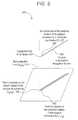
- FIG. 5illustrates a graphic showing the computation of the 3D error in navigation volume.
- FIG. 6illustrates a graphic showing the computation of the 2D error in an image.
- FIG. 7illustrates a method for assessing the accuracy of a surgical navigation system in accordance with an embodiment of the present invention.
- FIG. 8illustrates a method for computing the navigation error in a 3D navigation volume.
- FIG. 9illustrates a method for computing the navigation error in a 2D image.
- FIG. 1illustrates a system 100 that may be used for image guided surgery in accordance with an embodiment of the present invention.
- the system 100illustrates, as an example of a medical imaging unit, a C-arm unit 110 .
- the medical imaging unitmay be other medical imaging equipment, such as an ultrasound unit, for example. Accordingly, any medical imaging equipment may be used.
- the C-arm unit 110is connected to a computer unit 120 .
- the connection between the C-arm unit 110 and the computer unit 120may be wired or wireless.
- the computer unit 120may be any equipment or software that permits electronic medical images, such as x-rays, ultrasound, CT, MRI, EBT, MR, or nuclear medicine for example, to be electronically acquired, stored, or transmitted for viewing and operation.
- the computer unit 120may receive input from a user.
- the computer unit 120represents, in general, equipment and software.
- the actual physical computer unitsmay be separate units, part of a single unit, a computer system, or part of a computer system.
- the computer unit 120may be connected to other devices via an electronic network.
- the connection of the computer unit 120 to an electronic networkis illustrated by line 140 .
- the connection between the network 140 and the computer unit 120may be wired or wireless.
- the computer unit 120may also be connected to a display unit 130 .
- the connection between the computer unit 120 and the display unit 130may be wired or wireless.
- the display unit 130may be a single display unit or multiple display units. Additionally, the display unit 130 may be a two-dimensional display unit or a three-dimensional display unit, for example. Accordingly, any display unit may be used in accordance with the present invention.
- Element 105represents a patient and element 107 represents a table on which the patient is lying.
- Elements 150 , 160 , and 170are electronic sensors that may identify their location with reference to a reference frame and with reference to each other. Although three sensors 150 - 170 are shown, any number of sensors may be used.
- the sensors 150 - 170are generally in electronic communication with the computer unit 120 .
- Element 112represents an x-ray source and element 115 represents an x-ray detector.
- the x-ray detector 115may be, for example, an image intensifier or flat panel detector.
- the electronic communicationmay be over a wire or may be transmitted in a wireless fashion.
- the components of the system 100may be single units, separate units, may be integrated in various forms, and may be implemented in hardware and/or in software.
- FIG. 2illustrates a graphic 200 illustrating the predicted instrument location and the actual instrument location.
- the graphic 200illustrates a “confirmation shot” that shows the predicted instrument location 210 superimposed onto the actual instrument location 220 as part of an X-ray of a patient's anatomy.
- the actual instrument location 220may be illustrated as a shadow on the graphic 200 .
- the graphic 200is only an example and the actual instrument location 220 and the predicted instrument location 210 may be represented in a manner different than that shown in the graphic 200 .
- FIG. 3illustrates an image 300 illustrating the contrast between patient anatomy and a surgical instrument.
- the image 300illustrates an X-ray image showing the surgical instrument 320 .
- the surgical instrument 320represents the actual location of the surgical instrument.
- the image 300may represent a “confirmation shot” prior to superposition of the predicted instrument location.
- the image 300may be segmented by computer software to identify the surgical instrument 320 .
- computer softwaremay segment and extract the tip of the surgical instrument 320 from the image 300 .
- the segmentation of the surgical instrument 320may be performed by edge detection or pattern recognition algorithms to achieve an accurate localization of the tip of the surgical instrument 320 within the image 300 .
- the computer softwaremay utilize the contrast between the anatomical structure of the image 300 and the surgical instrument 320 .
- FIG. 4illustrates an image 400 which is the image 300 after edge detection segmentation has been performed.
- the image 400shows the surgical instrument shadow 420 .
- FIG. 4is only an example and other type of segmentation may be performed to obtain the surgical instrument shadow.
- the computer softwaremay compute the navigation error between the actual location of the surgical instrument and the predicted location of the surgical instrument.
- two quantitiesmay be computed, the 3D error computation in navigation volume and the 2D error computation in the navigated image.
- FIG. 5illustrates a graphic 500 showing the computation of the 3D error in navigation volume.
- the coordinates 520(u a ,v a ) denote the pixel coordinates 520 of the actual location of the surgical instrument tip computed using image segmentation in the image.
- the coordinates 530(u p ,v p ) denote the pixel coordinates 530 of the predicted location of the surgical instrument tip in the image.
- the back-projection line 510 L(u a ,v a ) stemming from the pixel coordinates 520 of the actual location of the surgical instrument tip 520 in the imageis computed using camera calibration parameters.
- the computation of the back-projection line stemming from an image pixel (u,v)is performed once the camera calibration parameters have been computed.
- the camera calibrationis a process that aims at estimating the X-ray image formation model. The estimation enables the system to compute the 2D projection of a 3D point or inversely to compute the back-projection line associated with a 2D pixel within the calibrated image.
- the output of the camera calibration processis generally referred to as camera parameters or projection parameters.
- the parametersenable the passage from a 3D point in the space to its 2D projection and the computation, for a 2D pixel, of the back-projection line associated with that pixel.
- the back-projection line 510 L(u a ,v a )is computed in the tracker coordinates system.
- the surgical instrument in navigation volume 540is also shown in the graphic 500 .
- the distance between the back-projection line 510 L(u a ,v a ) and the 3D coordinates of the predicted location of the surgical instrument tip in the tracker coordinates (X,Y,Z) t 550is computed.
- the 3D coordinates of the surgical instrument tip (X,Y,Z) t 550 in the tracker coordinates systemare known because the surgical instrument may be mounted onto an electromagnetic receiver and its tip has previously been calibrated. For example, the surgical instrument tip may be calibrated using fixed points calibration.
- the distance between the back-projection line 510 L(u a ,v a ) and the 3D coordinates of the surgical instrument tip (X,Y,Z) t 550is the navigation error in the 3D navigation volume 560 .
- the Distance function used to compute the 3D erroris the distance between a Line L(u a ,v a ) and a 3D point (X,Y,Z) t .
- the distance between the Line L(u a ,v a ) and the 3D point (X,Y,Z) tmay be geometrically defined as the length measurement of the line segment stemming from the 3D point and which is perpendicular to the Line L(u,v). This distance is measured in the plane defined by the Line L(u,v) and the 3D point (X,Y,Z) t .
- the mathematical formula to compute the distance between the Line L(u a ,v a ) and the 3D point (X,Y,Z) tmay depend on the parameters used to define the 3D line. For example, the distance between the 3D point (x 0 ,y 0 ,z 0 ) and the line L defined as the line that passes through (x 1 ,y 1 ,z 1 ) with its orientation defined by the vector (a,b,c)t is given by:
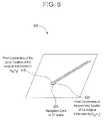
- FIG. 6illustrates a graphic 600 showing the computation of the 2D error in an image.
- the 2D error in the imagemay also be called the 2D projection error.
- the 3D coordinates of the predicted location of the surgical instrument tip (X,Y,Z) tare projected onto the image using camera projection parameters and performing a projection operation.
- the computation of the back-projection line stemming from an image pixel (u,v)is performed once the camera calibration parameters have been computed.
- the camera calibrationis a process that aims at estimating the X-ray image formation model. The estimation enables the system to compute the 2D projection of a 3D point or inversely to compute the back-projection line associated with a 2D pixel within the calibrated image.
- the output of the camera calibration processis generally referred to as camera parameters or projection parameters.
- the parametersenable the passage from a 3D point in the space to its 2D projection and the computation, for a 2D pixel, of the back-projection line associated with that pixel.
- the projection of the 3D coordinates of the predicted location of the surgical instrumentyields the predicted 2D instrument location on the image.
- the coordinates 630 (u p ,v p )denote the pixel coordinates 630 of the predicted location of the surgical instrument tip in the image.
- the coordinates 620 (u a ,v a )denote the pixel coordinates 620 of the actual location of the surgical instrument tip computed using image segmentation in the image.
- the distance between the predicted projection 630 (u p ,v p ) and the actual projection 620 (u a ,v a ) of the surgical instrument tip on the imageis the 2D navigation error 660 in the image.
- the 2D navigation error 660 in the imagemay also be called the 2D navigation error in the confirmation shot.
- the distance Dis the difference in 2D image space between the predicted location of the surgical instrument tip 630 and the actual location of the surgical instrument tip 620 .
- the distance Dis equal to the 2D navigation error 660 , E 2d .
- the navigation error in 3D navigation volume 560 and the 2D navigation error 660may be computed and quantified.
- the quantified error valuesmay be compared with a threshold error value. In an embodiment, if one of the quantified error values is greater than the associated threshold error value, the user may be alerted that the navigation system is inaccurate. It should be noted that it is not necessary that both the navigation error in 3D navigation volume 560 and the 2D navigation error 660 are used. In an embodiment one of the values may be used. In another embodiment, both of the values may be used. The embodiments of the present invention free the surgeon from determining whether the surgical navigation system is accurate.
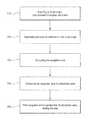
- FIG. 7illustrates a method 700 for assessing the accuracy of a surgical navigation system in accordance with an embodiment of the present invention.
- an X-ray image that captures the surgical instrumentis acquired.
- the X-ray imagemay be a confirmation shot.
- the X-ray image acquired at step 710may be segmented.
- the segmentingmay include image processing in order to segment and extract the tip of the surgical instrument in the X-ray image.
- the segmentation of the surgical instrumentmay be performed using an edge detection or pattern recognition algorithm to achieve accurate localization of the surgical instrument tip within the X-ray image.
- the navigation error between the predicted location of the surgical instrument tip and the actual location of the surgical instrument tipis computed.
- the navigation errormay be the navigation error in a 3D navigation volume. In an embodiment the navigation error may be the 2D navigation error.
- the navigation errormay be compared to a threshold value. If the navigation error is greater than a threshold value, at step 750 a user may be alerted that the surgical navigation system is operating with insufficient accuracy.
- FIG. 8illustrates a method 800 for computing the navigation error in a 3D navigation volume.
- a back-projection linethat stems from the pixel coordinates of the actual location of the surgical instrument tip is computed.
- the back-projection lineis computed in the tracker coordinates system.
- the computation of the back-projection line stemming from an image pixel (u,v)is performed once the camera calibration parameters have been computed.
- the camera calibrationis a process that aims at estimating the X-ray image formation model. The estimation enables the computation of the 2D projection of a 3D point or inversely to compute the back-projection line associated with a 2D pixel within the calibrated image.
- the output of the camera calibration processis generally referred to as camera parameters or projection parameters.
- the parametersenable the passage from a 3D point in the space to its 2D projection and the computation, for a 2D pixel, of the back-projection line associated with that pixel.
- the distance between the back-projection line and the 3D coordinates of the predicted location of the surgical instrument tipis computed.
- the 3D coordinates of the surgical instrument tip in the tracker coordinates systemare known because the surgical instrument may be mounted onto an electromagnetic receiver and its tip has previously been calibrated.
- the surgical instrument tipmay be calibrated using fixed points calibration.
- the distance between the back-projection line and the 3D coordinates of the surgical instrument tipis the navigation error in the 3D navigation volume.
- FIG. 9illustrates a method 900 for computing the navigation error in a 2D image.
- 3D coordinates of the predicted location of the surgical instrument tipare projected onto an image.
- the 3D coordinates of the predicted location of the surgical instrument tipare projected onto the image using camera projection parameters. The projection of the 3D coordinates of the predicted location of the surgical instrument yields the predicted 2D instrument location on the image.
- the distance between the predicted projection and the actual projection of the surgical instrument tip on the imageis computed.
- the distance between the predicted projection and the actual projection of the surgical instrument tip on the imageis the 2D navigation error in the image.
- the 2D navigation error in the imagemay also be called the 2D navigation error in the confirmation shot.
- the system and method 700 described abovemay be carried out as part of a computer-readable storage medium including a set of instructions for a computer.
- the set of instructionsmay include an acquisition routine for acquiring an X-ray image that captures the surgical instrument.
- the X-ray imagemay be a confirmation shot.
- the set of instructionsmay also include a segmentation routine for segmenting the acquired X-ray image.
- the segmentingmay include image processing in order to segment and extract the tip of the surgical instrument in the X-ray image.
- the segmentation of the surgical instrumentmay be performed using an edge detection or pattern recognition algorithm to achieve accurate localization of the surgical instrument tip within the X-ray image.
- the set of instructionsmay also include a computation routine for computing the navigation error between the predicted location of the surgical instrument tip and the actual location of the surgical instrument tip.
- the navigation errormay be the navigation error in a 3D navigation volume.
- the navigation errormay be the 2D navigation error.
- the set of instructionsmay also include a comparison routine for comparing the navigation error with a threshold value.
- the set of instructionsmay also include an alerting routine for alerting a user if the navigation error is greater than a threshold value that the surgical navigation system may be operating with insufficient accuracy.
- the system and method 800 described abovemay be carried out as part of a computer-readable storage medium including a set of instructions for a computer.
- the set of instructionsmay include a first computation routine for computing a back-projection line that stems from the pixel coordinates of the actual location of the surgical instrument tip.
- the back-projection lineis computed in the tracker coordinates system.
- the set of instructionsmay also include a second computation routine for computing the distance between the back-projection line and the 3D coordinates of the predicted location of the surgical instrument tip.
- the 3D coordinates of the surgical instrument tip in the tracker coordinates systemare known because the surgical instrument may be mounted onto an electromagnetic receiver and its tip has previously been calibrated. For example, the surgical instrument tip may be calibrated using fixed points calibration.
- the distance between the back-projection line and the 3D coordinates of the surgical instrument tipis the navigation error in the 3D navigation volume.
- the system and method 900 described abovemay be carried out as part of a computer-readable storage medium including a set of instructions for a computer.
- the set of instructionsmay include a first computation routine for projecting the 3D coordinates of the predicted location of the surgical instrument tip onto an image.
- the 3D coordinates of the predicted location of the surgical instrument tipare projected onto the image using camera projection parameters.
- the projection of the 3D coordinates of the predicted location of the surgical instrumentyields the predicted 2D instrument location on the image.
- the set of instructionsmay also include a second computation routine for computing the distance between the predicted projection and the actual projection of the surgical instrument tip on the image.
- the distance between the predicted projection and the actual projection of the surgical instrument tip on the imageis the 2D navigation error in the image.
- the 2D navigation error in the imagemay also be called the 2D navigation error in the confirmation shot.
Landscapes
- Engineering & Computer Science (AREA)
- Health & Medical Sciences (AREA)
- Life Sciences & Earth Sciences (AREA)
- Physics & Mathematics (AREA)
- Medical Informatics (AREA)
- Heart & Thoracic Surgery (AREA)
- Veterinary Medicine (AREA)
- Public Health (AREA)
- General Health & Medical Sciences (AREA)
- Pathology (AREA)
- Animal Behavior & Ethology (AREA)
- Biomedical Technology (AREA)
- Biophysics (AREA)
- Molecular Biology (AREA)
- Surgery (AREA)
- Radiology & Medical Imaging (AREA)
- Optics & Photonics (AREA)
- Nuclear Medicine, Radiotherapy & Molecular Imaging (AREA)
- High Energy & Nuclear Physics (AREA)
- Geometry (AREA)
- Computer Vision & Pattern Recognition (AREA)
- General Physics & Mathematics (AREA)
- Theoretical Computer Science (AREA)
- Human Computer Interaction (AREA)
- Apparatus For Radiation Diagnosis (AREA)
Abstract
Description
E3d=Distance[L(ua, va), (X,Y,Z)t] Equation 1
where E3dis the navigation error in 3D navigation volume. In Equation 1, the Distance function used to compute the 3D error is the distance between a Line L(ua,va) and a 3D point (X,Y,Z)t. The distance between the Line L(ua,va) and the 3D point (X,Y,Z)tmay be geometrically defined as the length measurement of the line segment stemming from the 3D point and which is perpendicular to the Line L(u,v). This distance is measured in the plane defined by the Line L(u,v) and the 3D point (X,Y,Z)t.
E2d=D=sqrt[(up−ua)2+(vp−va)2] Equation 3
Claims (20)
Priority Applications (1)
| Application Number | Priority Date | Filing Date | Title |
|---|---|---|---|
| US11/767,281US9468412B2 (en) | 2007-06-22 | 2007-06-22 | System and method for accuracy verification for image based surgical navigation |
Applications Claiming Priority (1)
| Application Number | Priority Date | Filing Date | Title |
|---|---|---|---|
| US11/767,281US9468412B2 (en) | 2007-06-22 | 2007-06-22 | System and method for accuracy verification for image based surgical navigation |
Publications (2)
| Publication Number | Publication Date |
|---|---|
| US20080319311A1 US20080319311A1 (en) | 2008-12-25 |
| US9468412B2true US9468412B2 (en) | 2016-10-18 |
Family
ID=40137222
Family Applications (1)
| Application Number | Title | Priority Date | Filing Date |
|---|---|---|---|
| US11/767,281Active2034-07-30US9468412B2 (en) | 2007-06-22 | 2007-06-22 | System and method for accuracy verification for image based surgical navigation |
Country Status (1)
| Country | Link |
|---|---|
| US (1) | US9468412B2 (en) |
Cited By (2)
| Publication number | Priority date | Publication date | Assignee | Title |
|---|---|---|---|---|
| US11350995B2 (en) | 2016-10-05 | 2022-06-07 | Nuvasive, Inc. | Surgical navigation systems and methods |
| US11612440B2 (en) | 2019-09-05 | 2023-03-28 | Nuvasive, Inc. | Surgical instrument tracking devices and related methods |
Families Citing this family (169)
| Publication number | Priority date | Publication date | Assignee | Title |
|---|---|---|---|---|
| US8190238B2 (en)* | 2005-12-09 | 2012-05-29 | Hansen Medical, Inc. | Robotic catheter system and methods |
| US8219178B2 (en) | 2007-02-16 | 2012-07-10 | Catholic Healthcare West | Method and system for performing invasive medical procedures using a surgical robot |
| US10653497B2 (en) | 2006-02-16 | 2020-05-19 | Globus Medical, Inc. | Surgical tool systems and methods |
| US10893912B2 (en) | 2006-02-16 | 2021-01-19 | Globus Medical Inc. | Surgical tool systems and methods |
| US10357184B2 (en) | 2012-06-21 | 2019-07-23 | Globus Medical, Inc. | Surgical tool systems and method |
| US20090036900A1 (en) | 2007-02-02 | 2009-02-05 | Hansen Medical, Inc. | Surgery methods using a robotic instrument system |
| US9403020B2 (en) | 2008-11-04 | 2016-08-02 | Nevro Corporation | Modeling positions of implanted devices in a patient |
| US9642555B2 (en)* | 2008-11-20 | 2017-05-09 | Medtronic, Inc. | Subcutaneous lead guidance |
| US9254123B2 (en) | 2009-04-29 | 2016-02-09 | Hansen Medical, Inc. | Flexible and steerable elongate instruments with shape control and support elements |
| WO2011044421A1 (en) | 2009-10-08 | 2011-04-14 | C. R. Bard, Inc. | Spacers for use with an ultrasound probe |
| CN103228219B (en) | 2010-08-09 | 2016-04-27 | C·R·巴德股份有限公司 | Support and Covering Structures for Ultrasound Probe Heads |
| US8805519B2 (en) | 2010-09-30 | 2014-08-12 | Nevro Corporation | Systems and methods for detecting intrathecal penetration |
| US8965482B2 (en)* | 2010-09-30 | 2015-02-24 | Nevro Corporation | Systems and methods for positioning implanted devices in a patient |
| US20120191079A1 (en) | 2011-01-20 | 2012-07-26 | Hansen Medical, Inc. | System and method for endoluminal and translumenal therapy |
| US9308050B2 (en) | 2011-04-01 | 2016-04-12 | Ecole Polytechnique Federale De Lausanne (Epfl) | Robotic system and method for spinal and other surgeries |
| US20130030363A1 (en) | 2011-07-29 | 2013-01-31 | Hansen Medical, Inc. | Systems and methods utilizing shape sensing fibers |
| AU2013211937B2 (en) | 2012-01-25 | 2016-07-28 | Nevro Corporation | Lead anchors and associated systems and methods |
| US8676331B2 (en) | 2012-04-02 | 2014-03-18 | Nevro Corporation | Devices for controlling spinal cord modulation for inhibiting pain, and associated systems and methods, including controllers for automated parameter selection |
| EP2861153A4 (en)* | 2012-06-15 | 2016-10-19 | Bard Inc C R | Apparatus and methods for detection of a removable cap on an ultrasound probe |
| US10874466B2 (en) | 2012-06-21 | 2020-12-29 | Globus Medical, Inc. | System and method for surgical tool insertion using multiaxis force and moment feedback |
| US10231791B2 (en) | 2012-06-21 | 2019-03-19 | Globus Medical, Inc. | Infrared signal based position recognition system for use with a robot-assisted surgery |
| US11864745B2 (en) | 2012-06-21 | 2024-01-09 | Globus Medical, Inc. | Surgical robotic system with retractor |
| US12004905B2 (en) | 2012-06-21 | 2024-06-11 | Globus Medical, Inc. | Medical imaging systems using robotic actuators and related methods |
| US12262954B2 (en) | 2012-06-21 | 2025-04-01 | Globus Medical, Inc. | Surgical robotic automation with tracking markers |
| EP2863827B1 (en) | 2012-06-21 | 2022-11-16 | Globus Medical, Inc. | Surgical robot platform |
| US12329593B2 (en) | 2012-06-21 | 2025-06-17 | Globus Medical, Inc. | Surgical robotic automation with tracking markers |
| US11896446B2 (en) | 2012-06-21 | 2024-02-13 | Globus Medical, Inc | Surgical robotic automation with tracking markers |
| US20150032164A1 (en) | 2012-06-21 | 2015-01-29 | Globus Medical, Inc. | Methods for Performing Invasive Medical Procedures Using a Surgical Robot |
| US10646280B2 (en) | 2012-06-21 | 2020-05-12 | Globus Medical, Inc. | System and method for surgical tool insertion using multiaxis force and moment feedback |
| US10758315B2 (en) | 2012-06-21 | 2020-09-01 | Globus Medical Inc. | Method and system for improving 2D-3D registration convergence |
| US10799298B2 (en) | 2012-06-21 | 2020-10-13 | Globus Medical Inc. | Robotic fluoroscopic navigation |
| US11857266B2 (en) | 2012-06-21 | 2024-01-02 | Globus Medical, Inc. | System for a surveillance marker in robotic-assisted surgery |
| US10842461B2 (en) | 2012-06-21 | 2020-11-24 | Globus Medical, Inc. | Systems and methods of checking registrations for surgical systems |
| US11793570B2 (en) | 2012-06-21 | 2023-10-24 | Globus Medical Inc. | Surgical robotic automation with tracking markers |
| US11607149B2 (en) | 2012-06-21 | 2023-03-21 | Globus Medical Inc. | Surgical tool systems and method |
| US11317971B2 (en) | 2012-06-21 | 2022-05-03 | Globus Medical, Inc. | Systems and methods related to robotic guidance in surgery |
| US11298196B2 (en) | 2012-06-21 | 2022-04-12 | Globus Medical Inc. | Surgical robotic automation with tracking markers and controlled tool advancement |
| US11974822B2 (en) | 2012-06-21 | 2024-05-07 | Globus Medical Inc. | Method for a surveillance marker in robotic-assisted surgery |
| US11395706B2 (en) | 2012-06-21 | 2022-07-26 | Globus Medical Inc. | Surgical robot platform |
| US11786324B2 (en) | 2012-06-21 | 2023-10-17 | Globus Medical, Inc. | Surgical robotic automation with tracking markers |
| US11116576B2 (en) | 2012-06-21 | 2021-09-14 | Globus Medical Inc. | Dynamic reference arrays and methods of use |
| US10350013B2 (en) | 2012-06-21 | 2019-07-16 | Globus Medical, Inc. | Surgical tool systems and methods |
| US10624710B2 (en) | 2012-06-21 | 2020-04-21 | Globus Medical, Inc. | System and method for measuring depth of instrumentation |
| US12310683B2 (en) | 2012-06-21 | 2025-05-27 | Globus Medical, Inc. | Surgical tool systems and method |
| US11864839B2 (en) | 2012-06-21 | 2024-01-09 | Globus Medical Inc. | Methods of adjusting a virtual implant and related surgical navigation systems |
| US11399900B2 (en) | 2012-06-21 | 2022-08-02 | Globus Medical, Inc. | Robotic systems providing co-registration using natural fiducials and related methods |
| US11045267B2 (en) | 2012-06-21 | 2021-06-29 | Globus Medical, Inc. | Surgical robotic automation with tracking markers |
| US11253327B2 (en) | 2012-06-21 | 2022-02-22 | Globus Medical, Inc. | Systems and methods for automatically changing an end-effector on a surgical robot |
| US11589771B2 (en) | 2012-06-21 | 2023-02-28 | Globus Medical Inc. | Method for recording probe movement and determining an extent of matter removed |
| US11857149B2 (en) | 2012-06-21 | 2024-01-02 | Globus Medical, Inc. | Surgical robotic systems with target trajectory deviation monitoring and related methods |
| US10136954B2 (en) | 2012-06-21 | 2018-11-27 | Globus Medical, Inc. | Surgical tool systems and method |
| US12220120B2 (en) | 2012-06-21 | 2025-02-11 | Globus Medical, Inc. | Surgical robotic system with retractor |
| US11963755B2 (en) | 2012-06-21 | 2024-04-23 | Globus Medical Inc. | Apparatus for recording probe movement |
| US20140148673A1 (en) | 2012-11-28 | 2014-05-29 | Hansen Medical, Inc. | Method of anchoring pullwire directly articulatable region in catheter |
| US20140277334A1 (en) | 2013-03-14 | 2014-09-18 | Hansen Medical, Inc. | Active drives for robotic catheter manipulators |
| US9326822B2 (en) | 2013-03-14 | 2016-05-03 | Hansen Medical, Inc. | Active drives for robotic catheter manipulators |
| US9408669B2 (en) | 2013-03-15 | 2016-08-09 | Hansen Medical, Inc. | Active drive mechanism with finite range of motion |
| US20140276936A1 (en) | 2013-03-15 | 2014-09-18 | Hansen Medical, Inc. | Active drive mechanism for simultaneous rotation and translation |
| US9265935B2 (en) | 2013-06-28 | 2016-02-23 | Nevro Corporation | Neurological stimulation lead anchors and associated systems and methods |
| US9480860B2 (en)* | 2013-09-27 | 2016-11-01 | Varian Medical Systems, Inc. | System and methods for processing images to measure multi-leaf collimator, collimator jaw, and collimator performance utilizing pre-entered characteristics |
| US9283048B2 (en) | 2013-10-04 | 2016-03-15 | KB Medical SA | Apparatus and systems for precise guidance of surgical tools |
| US9241771B2 (en) | 2014-01-15 | 2016-01-26 | KB Medical SA | Notched apparatus for guidance of an insertable instrument along an axis during spinal surgery |
| WO2015121311A1 (en) | 2014-02-11 | 2015-08-20 | KB Medical SA | Sterile handle for controlling a robotic surgical system from a sterile field |
| US11033182B2 (en) | 2014-02-21 | 2021-06-15 | 3Dintegrated Aps | Set comprising a surgical instrument |
| US10046140B2 (en) | 2014-04-21 | 2018-08-14 | Hansen Medical, Inc. | Devices, systems, and methods for controlling active drive systems |
| EP3134022B1 (en) | 2014-04-24 | 2018-01-10 | KB Medical SA | Surgical instrument holder for use with a robotic surgical system |
| CN106999248B (en) | 2014-06-19 | 2021-04-06 | Kb医疗公司 | Systems and methods for performing minimally invasive surgery |
| US10357257B2 (en) | 2014-07-14 | 2019-07-23 | KB Medical SA | Anti-skid surgical instrument for use in preparing holes in bone tissue |
| US10765438B2 (en) | 2014-07-14 | 2020-09-08 | KB Medical SA | Anti-skid surgical instrument for use in preparing holes in bone tissue |
| EP3226781B1 (en) | 2014-12-02 | 2018-08-01 | KB Medical SA | Robot assisted volume removal during surgery |
| US10013808B2 (en) | 2015-02-03 | 2018-07-03 | Globus Medical, Inc. | Surgeon head-mounted display apparatuses |
| WO2016131903A1 (en) | 2015-02-18 | 2016-08-25 | KB Medical SA | Systems and methods for performing minimally invasive spinal surgery with a robotic surgical system using a percutaneous technique |
| US9789321B2 (en) | 2015-04-03 | 2017-10-17 | Nevro Corp. | Couplings for implanted leads and external stimulators, and associated systems and methods |
| CN108024806B (en) | 2015-07-21 | 2022-07-01 | 3D集成公司 | Cannula assembly kit, trocar assembly kit, sleeve assembly, minimally invasive surgical system and method thereof |
| US11020144B2 (en) | 2015-07-21 | 2021-06-01 | 3Dintegrated Aps | Minimally invasive surgery system |
| US10058394B2 (en) | 2015-07-31 | 2018-08-28 | Globus Medical, Inc. | Robot arm and methods of use |
| US10646298B2 (en) | 2015-07-31 | 2020-05-12 | Globus Medical, Inc. | Robot arm and methods of use |
| US10080615B2 (en) | 2015-08-12 | 2018-09-25 | Globus Medical, Inc. | Devices and methods for temporary mounting of parts to bone |
| JP6894431B2 (en) | 2015-08-31 | 2021-06-30 | ケービー メディカル エスアー | Robotic surgical system and method |
| US10034716B2 (en) | 2015-09-14 | 2018-07-31 | Globus Medical, Inc. | Surgical robotic systems and methods thereof |
| DK178899B1 (en) | 2015-10-09 | 2017-05-08 | 3Dintegrated Aps | A depiction system |
| US9771092B2 (en) | 2015-10-13 | 2017-09-26 | Globus Medical, Inc. | Stabilizer wheel assembly and methods of use |
| US11058378B2 (en) | 2016-02-03 | 2021-07-13 | Globus Medical, Inc. | Portable medical imaging system |
| US10842453B2 (en) | 2016-02-03 | 2020-11-24 | Globus Medical, Inc. | Portable medical imaging system |
| US10117632B2 (en) | 2016-02-03 | 2018-11-06 | Globus Medical, Inc. | Portable medical imaging system with beam scanning collimator |
| US11883217B2 (en) | 2016-02-03 | 2024-01-30 | Globus Medical, Inc. | Portable medical imaging system and method |
| US10448910B2 (en) | 2016-02-03 | 2019-10-22 | Globus Medical, Inc. | Portable medical imaging system |
| US10866119B2 (en) | 2016-03-14 | 2020-12-15 | Globus Medical, Inc. | Metal detector for detecting insertion of a surgical device into a hollow tube |
| EP3241518B1 (en) | 2016-04-11 | 2024-10-23 | Globus Medical, Inc | Surgical tool systems |
| US10463439B2 (en) | 2016-08-26 | 2019-11-05 | Auris Health, Inc. | Steerable catheter with shaft load distributions |
| US11241559B2 (en) | 2016-08-29 | 2022-02-08 | Auris Health, Inc. | Active drive for guidewire manipulation |
| US11039893B2 (en) | 2016-10-21 | 2021-06-22 | Globus Medical, Inc. | Robotic surgical systems |
| JP7233841B2 (en) | 2017-01-18 | 2023-03-07 | ケービー メディカル エスアー | Robotic Navigation for Robotic Surgical Systems |
| EP3351202B1 (en) | 2017-01-18 | 2021-09-08 | KB Medical SA | Universal instrument guide for robotic surgical systems |
| JP7583513B2 (en) | 2017-01-18 | 2024-11-14 | ケービー メディカル エスアー | Universal instrument guide for robotic surgical systems, surgical instrument system |
| US10980999B2 (en) | 2017-03-09 | 2021-04-20 | Nevro Corp. | Paddle leads and delivery tools, and associated systems and methods |
| US11071594B2 (en) | 2017-03-16 | 2021-07-27 | KB Medical SA | Robotic navigation of robotic surgical systems |
| US20180289432A1 (en) | 2017-04-05 | 2018-10-11 | Kb Medical, Sa | Robotic surgical systems for preparing holes in bone tissue and methods of their use |
| US11135015B2 (en) | 2017-07-21 | 2021-10-05 | Globus Medical, Inc. | Robot surgical platform |
| US11357548B2 (en) | 2017-11-09 | 2022-06-14 | Globus Medical, Inc. | Robotic rod benders and related mechanical and motor housings |
| EP3492032B1 (en) | 2017-11-09 | 2023-01-04 | Globus Medical, Inc. | Surgical robotic systems for bending surgical rods |
| US11794338B2 (en) | 2017-11-09 | 2023-10-24 | Globus Medical Inc. | Robotic rod benders and related mechanical and motor housings |
| US11134862B2 (en) | 2017-11-10 | 2021-10-05 | Globus Medical, Inc. | Methods of selecting surgical implants and related devices |
| US20190254753A1 (en) | 2018-02-19 | 2019-08-22 | Globus Medical, Inc. | Augmented reality navigation systems for use with robotic surgical systems and methods of their use |
| JP7225259B2 (en) | 2018-03-28 | 2023-02-20 | オーリス ヘルス インコーポレイテッド | Systems and methods for indicating probable location of instruments |
| WO2019191423A1 (en) | 2018-03-29 | 2019-10-03 | Nevro Corp. | Leads having sidewall openings, and associated systems and methods |
| US10573023B2 (en) | 2018-04-09 | 2020-02-25 | Globus Medical, Inc. | Predictive visualization of medical imaging scanner component movement |
| US11337742B2 (en) | 2018-11-05 | 2022-05-24 | Globus Medical Inc | Compliant orthopedic driver |
| US11278360B2 (en) | 2018-11-16 | 2022-03-22 | Globus Medical, Inc. | End-effectors for surgical robotic systems having sealed optical components |
| US11602402B2 (en) | 2018-12-04 | 2023-03-14 | Globus Medical, Inc. | Drill guide fixtures, cranial insertion fixtures, and related methods and robotic systems |
| US11744655B2 (en) | 2018-12-04 | 2023-09-05 | Globus Medical, Inc. | Drill guide fixtures, cranial insertion fixtures, and related methods and robotic systems |
| US11918313B2 (en) | 2019-03-15 | 2024-03-05 | Globus Medical Inc. | Active end effectors for surgical robots |
| US11806084B2 (en) | 2019-03-22 | 2023-11-07 | Globus Medical, Inc. | System for neuronavigation registration and robotic trajectory guidance, and related methods and devices |
| US11382549B2 (en) | 2019-03-22 | 2022-07-12 | Globus Medical, Inc. | System for neuronavigation registration and robotic trajectory guidance, and related methods and devices |
| US11419616B2 (en) | 2019-03-22 | 2022-08-23 | Globus Medical, Inc. | System for neuronavigation registration and robotic trajectory guidance, robotic surgery, and related methods and devices |
| US11571265B2 (en) | 2019-03-22 | 2023-02-07 | Globus Medical Inc. | System for neuronavigation registration and robotic trajectory guidance, robotic surgery, and related methods and devices |
| US20200297357A1 (en) | 2019-03-22 | 2020-09-24 | Globus Medical, Inc. | System for neuronavigation registration and robotic trajectory guidance, robotic surgery, and related methods and devices |
| US11317978B2 (en) | 2019-03-22 | 2022-05-03 | Globus Medical, Inc. | System for neuronavigation registration and robotic trajectory guidance, robotic surgery, and related methods and devices |
| US11045179B2 (en) | 2019-05-20 | 2021-06-29 | Global Medical Inc | Robot-mounted retractor system |
| US11628023B2 (en) | 2019-07-10 | 2023-04-18 | Globus Medical, Inc. | Robotic navigational system for interbody implants |
| US11571171B2 (en) | 2019-09-24 | 2023-02-07 | Globus Medical, Inc. | Compound curve cable chain |
| US12396692B2 (en) | 2019-09-24 | 2025-08-26 | Globus Medical, Inc. | Compound curve cable chain |
| US12329391B2 (en) | 2019-09-27 | 2025-06-17 | Globus Medical, Inc. | Systems and methods for robot-assisted knee arthroplasty surgery |
| US11890066B2 (en) | 2019-09-30 | 2024-02-06 | Globus Medical, Inc | Surgical robot with passive end effector |
| US12408929B2 (en) | 2019-09-27 | 2025-09-09 | Globus Medical, Inc. | Systems and methods for navigating a pin guide driver |
| US11864857B2 (en) | 2019-09-27 | 2024-01-09 | Globus Medical, Inc. | Surgical robot with passive end effector |
| US11426178B2 (en) | 2019-09-27 | 2022-08-30 | Globus Medical Inc. | Systems and methods for navigating a pin guide driver |
| US11510684B2 (en) | 2019-10-14 | 2022-11-29 | Globus Medical, Inc. | Rotary motion passive end effector for surgical robots in orthopedic surgeries |
| US11992373B2 (en) | 2019-12-10 | 2024-05-28 | Globus Medical, Inc | Augmented reality headset with varied opacity for navigated robotic surgery |
| US12133772B2 (en) | 2019-12-10 | 2024-11-05 | Globus Medical, Inc. | Augmented reality headset for navigated robotic surgery |
| US12220176B2 (en) | 2019-12-10 | 2025-02-11 | Globus Medical, Inc. | Extended reality instrument interaction zone for navigated robotic |
| US12064189B2 (en) | 2019-12-13 | 2024-08-20 | Globus Medical, Inc. | Navigated instrument for use in robotic guided surgery |
| US11464581B2 (en) | 2020-01-28 | 2022-10-11 | Globus Medical, Inc. | Pose measurement chaining for extended reality surgical navigation in visible and near infrared spectrums |
| US11382699B2 (en) | 2020-02-10 | 2022-07-12 | Globus Medical Inc. | Extended reality visualization of optical tool tracking volume for computer assisted navigation in surgery |
| US12414752B2 (en) | 2020-02-17 | 2025-09-16 | Globus Medical, Inc. | System and method of determining optimal 3-dimensional position and orientation of imaging device for imaging patient bones |
| US11207150B2 (en) | 2020-02-19 | 2021-12-28 | Globus Medical, Inc. | Displaying a virtual model of a planned instrument attachment to ensure correct selection of physical instrument attachment |
| US11253216B2 (en) | 2020-04-28 | 2022-02-22 | Globus Medical Inc. | Fixtures for fluoroscopic imaging systems and related navigation systems and methods |
| US11153555B1 (en) | 2020-05-08 | 2021-10-19 | Globus Medical Inc. | Extended reality headset camera system for computer assisted navigation in surgery |
| US11510750B2 (en) | 2020-05-08 | 2022-11-29 | Globus Medical, Inc. | Leveraging two-dimensional digital imaging and communication in medicine imagery in three-dimensional extended reality applications |
| US11382700B2 (en) | 2020-05-08 | 2022-07-12 | Globus Medical Inc. | Extended reality headset tool tracking and control |
| US11317973B2 (en) | 2020-06-09 | 2022-05-03 | Globus Medical, Inc. | Camera tracking bar for computer assisted navigation during surgery |
| US12070276B2 (en) | 2020-06-09 | 2024-08-27 | Globus Medical Inc. | Surgical object tracking in visible light via fiducial seeding and synthetic image registration |
| US11382713B2 (en) | 2020-06-16 | 2022-07-12 | Globus Medical, Inc. | Navigated surgical system with eye to XR headset display calibration |
| US11877807B2 (en) | 2020-07-10 | 2024-01-23 | Globus Medical, Inc | Instruments for navigated orthopedic surgeries |
| US11793588B2 (en) | 2020-07-23 | 2023-10-24 | Globus Medical, Inc. | Sterile draping of robotic arms |
| US11737831B2 (en) | 2020-09-02 | 2023-08-29 | Globus Medical Inc. | Surgical object tracking template generation for computer assisted navigation during surgical procedure |
| US11523785B2 (en) | 2020-09-24 | 2022-12-13 | Globus Medical, Inc. | Increased cone beam computed tomography volume length without requiring stitching or longitudinal C-arm movement |
| US12076091B2 (en) | 2020-10-27 | 2024-09-03 | Globus Medical, Inc. | Robotic navigational system |
| US11911112B2 (en) | 2020-10-27 | 2024-02-27 | Globus Medical, Inc. | Robotic navigational system |
| US11941814B2 (en) | 2020-11-04 | 2024-03-26 | Globus Medical Inc. | Auto segmentation using 2-D images taken during 3-D imaging spin |
| US11717350B2 (en) | 2020-11-24 | 2023-08-08 | Globus Medical Inc. | Methods for robotic assistance and navigation in spinal surgery and related systems |
| US12161433B2 (en) | 2021-01-08 | 2024-12-10 | Globus Medical, Inc. | System and method for ligament balancing with robotic assistance |
| US12150728B2 (en) | 2021-04-14 | 2024-11-26 | Globus Medical, Inc. | End effector for a surgical robot |
| US12178523B2 (en) | 2021-04-19 | 2024-12-31 | Globus Medical, Inc. | Computer assisted surgical navigation system for spine procedures |
| US11857273B2 (en) | 2021-07-06 | 2024-01-02 | Globus Medical, Inc. | Ultrasonic robotic surgical navigation |
| US11439444B1 (en) | 2021-07-22 | 2022-09-13 | Globus Medical, Inc. | Screw tower and rod reduction tool |
| US12213745B2 (en) | 2021-09-16 | 2025-02-04 | Globus Medical, Inc. | Extended reality systems for visualizing and controlling operating room equipment |
| US12238087B2 (en) | 2021-10-04 | 2025-02-25 | Globus Medical, Inc. | Validating credential keys based on combinations of credential value strings and input order strings |
| US12184636B2 (en) | 2021-10-04 | 2024-12-31 | Globus Medical, Inc. | Validating credential keys based on combinations of credential value strings and input order strings |
| US20230368330A1 (en) | 2021-10-20 | 2023-11-16 | Globus Medical, Inc. | Interpolation of medical images |
| US20230165639A1 (en) | 2021-12-01 | 2023-06-01 | Globus Medical, Inc. | Extended reality systems with three-dimensional visualizations of medical image scan slices |
| US11911115B2 (en) | 2021-12-20 | 2024-02-27 | Globus Medical Inc. | Flat panel registration fixture and method of using same |
| US12103480B2 (en) | 2022-03-18 | 2024-10-01 | Globus Medical Inc. | Omni-wheel cable pusher |
| US12048493B2 (en) | 2022-03-31 | 2024-07-30 | Globus Medical, Inc. | Camera tracking system identifying phantom markers during computer assisted surgery navigation |
| US12394086B2 (en) | 2022-05-10 | 2025-08-19 | Globus Medical, Inc. | Accuracy check and automatic calibration of tracked instruments |
| US12161427B2 (en) | 2022-06-08 | 2024-12-10 | Globus Medical, Inc. | Surgical navigation system with flat panel registration fixture |
| US12226169B2 (en) | 2022-07-15 | 2025-02-18 | Globus Medical, Inc. | Registration of 3D and 2D images for surgical navigation and robotic guidance without using radiopaque fiducials in the images |
| US20240020840A1 (en) | 2022-07-15 | 2024-01-18 | Globus Medical, Inc. | REGISTRATION OF 3D and 2D IMAGES FOR SURGICAL NAVIGATION AND ROBOTIC GUIDANCE WITHOUT USING RADIOPAQUE FIDUCIALS IN THE IMAGES |
| US12318150B2 (en) | 2022-10-11 | 2025-06-03 | Globus Medical Inc. | Camera tracking system for computer assisted surgery navigation |
Citations (11)
| Publication number | Priority date | Publication date | Assignee | Title |
|---|---|---|---|---|
| US5389101A (en)* | 1992-04-21 | 1995-02-14 | University Of Utah | Apparatus and method for photogrammetric surgical localization |
| US5603318A (en)* | 1992-04-21 | 1997-02-18 | University Of Utah Research Foundation | Apparatus and method for photogrammetric surgical localization |
| US6129668A (en)* | 1997-05-08 | 2000-10-10 | Lucent Medical Systems, Inc. | System and method to determine the location and orientation of an indwelling medical device |
| US6470207B1 (en)* | 1999-03-23 | 2002-10-22 | Surgical Navigation Technologies, Inc. | Navigational guidance via computer-assisted fluoroscopic imaging |
| US6484049B1 (en)* | 2000-04-28 | 2002-11-19 | Ge Medical Systems Global Technology Company, Llc | Fluoroscopic tracking and visualization system |
| US6560354B1 (en)* | 1999-02-16 | 2003-05-06 | University Of Rochester | Apparatus and method for registration of images to physical space using a weighted combination of points and surfaces |
| US20030208122A1 (en)* | 2000-03-01 | 2003-11-06 | Melkent Anthony J. | Multiple cannula image guided tool for image guided procedures |
| US20050096589A1 (en)* | 2003-10-20 | 2005-05-05 | Yehoshua Shachar | System and method for radar-assisted catheter guidance and control |
| US20050203386A1 (en)* | 2004-03-11 | 2005-09-15 | Siemens Aktiengesellschaft | Method of calibrating an X-ray imaging device |
| US20050281385A1 (en)* | 2004-06-02 | 2005-12-22 | Johnson Douglas K | Method and system for improved correction of registration error in a fluoroscopic image |
| US20060058616A1 (en)* | 2003-02-04 | 2006-03-16 | Joel Marquart | Interactive computer-assisted surgery system and method |
- 2007
- 2007-06-22USUS11/767,281patent/US9468412B2/enactiveActive
Patent Citations (11)
| Publication number | Priority date | Publication date | Assignee | Title |
|---|---|---|---|---|
| US5389101A (en)* | 1992-04-21 | 1995-02-14 | University Of Utah | Apparatus and method for photogrammetric surgical localization |
| US5603318A (en)* | 1992-04-21 | 1997-02-18 | University Of Utah Research Foundation | Apparatus and method for photogrammetric surgical localization |
| US6129668A (en)* | 1997-05-08 | 2000-10-10 | Lucent Medical Systems, Inc. | System and method to determine the location and orientation of an indwelling medical device |
| US6560354B1 (en)* | 1999-02-16 | 2003-05-06 | University Of Rochester | Apparatus and method for registration of images to physical space using a weighted combination of points and surfaces |
| US6470207B1 (en)* | 1999-03-23 | 2002-10-22 | Surgical Navigation Technologies, Inc. | Navigational guidance via computer-assisted fluoroscopic imaging |
| US20030208122A1 (en)* | 2000-03-01 | 2003-11-06 | Melkent Anthony J. | Multiple cannula image guided tool for image guided procedures |
| US6484049B1 (en)* | 2000-04-28 | 2002-11-19 | Ge Medical Systems Global Technology Company, Llc | Fluoroscopic tracking and visualization system |
| US20060058616A1 (en)* | 2003-02-04 | 2006-03-16 | Joel Marquart | Interactive computer-assisted surgery system and method |
| US20050096589A1 (en)* | 2003-10-20 | 2005-05-05 | Yehoshua Shachar | System and method for radar-assisted catheter guidance and control |
| US20050203386A1 (en)* | 2004-03-11 | 2005-09-15 | Siemens Aktiengesellschaft | Method of calibrating an X-ray imaging device |
| US20050281385A1 (en)* | 2004-06-02 | 2005-12-22 | Johnson Douglas K | Method and system for improved correction of registration error in a fluoroscopic image |
Cited By (2)
| Publication number | Priority date | Publication date | Assignee | Title |
|---|---|---|---|---|
| US11350995B2 (en) | 2016-10-05 | 2022-06-07 | Nuvasive, Inc. | Surgical navigation systems and methods |
| US11612440B2 (en) | 2019-09-05 | 2023-03-28 | Nuvasive, Inc. | Surgical instrument tracking devices and related methods |
Also Published As
| Publication number | Publication date |
|---|---|
| US20080319311A1 (en) | 2008-12-25 |
Similar Documents
| Publication | Publication Date | Title |
|---|---|---|
| US9468412B2 (en) | System and method for accuracy verification for image based surgical navigation | |
| US20220047247A1 (en) | Apparatus and method for real-time tracking of tissue structures | |
| US10405825B2 (en) | System and method for automatically determining calibration parameters of a fluoroscope | |
| US7711406B2 (en) | System and method for detection of electromagnetic radiation by amorphous silicon x-ray detector for metal detection in x-ray imaging | |
| US8165372B2 (en) | Information processing apparatus for registrating medical images, information processing method and program | |
| US8682413B2 (en) | Systems and methods for automated tracker-driven image selection | |
| US8694075B2 (en) | Intra-operative registration for navigated surgical procedures | |
| US9320569B2 (en) | Systems and methods for implant distance measurement | |
| US9715739B2 (en) | Bone fragment tracking | |
| US8131031B2 (en) | Systems and methods for inferred patient annotation | |
| US20080300477A1 (en) | System and method for correction of automated image registration | |
| US20080300478A1 (en) | System and method for displaying real-time state of imaged anatomy during a surgical procedure | |
| US20080119712A1 (en) | Systems and Methods for Automated Image Registration | |
| US20080119725A1 (en) | Systems and Methods for Visual Verification of CT Registration and Feedback | |
| CN106999247A (en) | For performing the trace labelling supporting structure of navigation surgical procedures and using its surface registration method | |
| US11127153B2 (en) | Radiation imaging device, image processing method, and image processing program | |
| US8126536B2 (en) | Method and apparatus for determining the frontal plane of the pelvic bone | |
| Wang et al. | Intra-op measurement of the mechanical axis deviation: an evaluation study on 19 human cadaver legs | |
| US20140316256A1 (en) | Display Of An Acquired Cine Loop For Procedure Navigation | |
| US20240398375A1 (en) | Spatial registration method for imaging devices | |
| US8067726B2 (en) | Universal instrument calibration system and method of use | |
| US9477686B2 (en) | Systems and methods for annotation and sorting of surgical images | |
| US20240216073A1 (en) | Method and device for generating an uncertainty map for guided percutaneous procedures | |
| KR20190123857A (en) | Apparatus for image overlay and method for the same | |
| US11432898B2 (en) | Tracing platforms and intra-operative systems and methods using same |
Legal Events
| Date | Code | Title | Description |
|---|---|---|---|
| AS | Assignment | Owner name:GENERAL ELECTRIC COMPANY, NEW YORK Free format text:ASSIGNMENT OF ASSIGNORS INTEREST;ASSIGNOR:HAMADEH, MOHAMED ALI;REEL/FRAME:019470/0536 Effective date:20070621 | |
| STCF | Information on status: patent grant | Free format text:PATENTED CASE | |
| AS | Assignment | Owner name:STRYKER EUROPEAN HOLDINGS I, LLC, MICHIGAN Free format text:ASSIGNMENT OF ASSIGNORS INTEREST;ASSIGNOR:GENERAL ELECTRIC COMPANY;REEL/FRAME:046020/0621 Effective date:20171206 | |
| MAFP | Maintenance fee payment | Free format text:PAYMENT OF MAINTENANCE FEE, 4TH YEAR, LARGE ENTITY (ORIGINAL EVENT CODE: M1551); ENTITY STATUS OF PATENT OWNER: LARGE ENTITY Year of fee payment:4 | |
| AS | Assignment | Owner name:STRYKER EUROPEAN HOLDINGS III, LLC, DELAWARE Free format text:NUNC PRO TUNC ASSIGNMENT;ASSIGNOR:STRYKER EUROPEAN HOLDINGS I, LLC;REEL/FRAME:056969/0771 Effective date:20210219 Owner name:STRYKER EUROPEAN OPERATIONS HOLDINGS LLC, MICHIGAN Free format text:CHANGE OF NAME;ASSIGNOR:STRYKER EUROPEAN HOLDINGS III, LLC;REEL/FRAME:056969/0893 Effective date:20190226 | |
| MAFP | Maintenance fee payment | Free format text:PAYMENT OF MAINTENANCE FEE, 8TH YEAR, LARGE ENTITY (ORIGINAL EVENT CODE: M1552); ENTITY STATUS OF PATENT OWNER: LARGE ENTITY Year of fee payment:8 | |
| AS | Assignment | Owner name:STRYKER EUROPEAN OPERATIONS HOLDINGS LLC, MICHIGAN Free format text:CHANGE OF ADDRESS;ASSIGNOR:STRYKER EUROPEAN OPERATIONS HOLDINGS LLC;REEL/FRAME:069730/0754 Effective date:20241217 |