US9468364B2 - Intravascular catheter with hood and image processing systems - Google Patents
Intravascular catheter with hood and image processing systemsDownload PDFInfo
- Publication number
- US9468364B2 US9468364B2US12/618,306US61830609AUS9468364B2US 9468364 B2US9468364 B2US 9468364B2US 61830609 AUS61830609 AUS 61830609AUS 9468364 B2US9468364 B2US 9468364B2
- Authority
- US
- United States
- Prior art keywords
- tissue
- hood
- ablation
- tissue region
- imaging
- Prior art date
- Legal status (The legal status is an assumption and is not a legal conclusion. Google has not performed a legal analysis and makes no representation as to the accuracy of the status listed.)
- Active, expires
Links
Images


Classifications
- A—HUMAN NECESSITIES
- A61—MEDICAL OR VETERINARY SCIENCE; HYGIENE
- A61B—DIAGNOSIS; SURGERY; IDENTIFICATION
- A61B5/00—Measuring for diagnostic purposes; Identification of persons
- A61B5/0059—Measuring for diagnostic purposes; Identification of persons using light, e.g. diagnosis by transillumination, diascopy, fluorescence
- A61B5/0082—Measuring for diagnostic purposes; Identification of persons using light, e.g. diagnosis by transillumination, diascopy, fluorescence adapted for particular medical purposes
- A61B5/0084—Measuring for diagnostic purposes; Identification of persons using light, e.g. diagnosis by transillumination, diascopy, fluorescence adapted for particular medical purposes for introduction into the body, e.g. by catheters
- A—HUMAN NECESSITIES
- A61—MEDICAL OR VETERINARY SCIENCE; HYGIENE
- A61B—DIAGNOSIS; SURGERY; IDENTIFICATION
- A61B1/00—Instruments for performing medical examinations of the interior of cavities or tubes of the body by visual or photographical inspection, e.g. endoscopes; Illuminating arrangements therefor
- A61B1/04—Instruments for performing medical examinations of the interior of cavities or tubes of the body by visual or photographical inspection, e.g. endoscopes; Illuminating arrangements therefor combined with photographic or television appliances
- A61B1/05—Instruments for performing medical examinations of the interior of cavities or tubes of the body by visual or photographical inspection, e.g. endoscopes; Illuminating arrangements therefor combined with photographic or television appliances characterised by the image sensor, e.g. camera, being in the distal end portion
- A—HUMAN NECESSITIES
- A61—MEDICAL OR VETERINARY SCIENCE; HYGIENE
- A61B—DIAGNOSIS; SURGERY; IDENTIFICATION
- A61B5/00—Measuring for diagnostic purposes; Identification of persons
- A61B5/01—Measuring temperature of body parts ; Diagnostic temperature sensing, e.g. for malignant or inflamed tissue
- A—HUMAN NECESSITIES
- A61—MEDICAL OR VETERINARY SCIENCE; HYGIENE
- A61B—DIAGNOSIS; SURGERY; IDENTIFICATION
- A61B5/00—Measuring for diagnostic purposes; Identification of persons
- A61B5/02—Detecting, measuring or recording for evaluating the cardiovascular system, e.g. pulse, heart rate, blood pressure or blood flow
- A61B5/024—Measuring pulse rate or heart rate
- A61B5/0245—Measuring pulse rate or heart rate by using sensing means generating electric signals, i.e. ECG signals
- A—HUMAN NECESSITIES
- A61—MEDICAL OR VETERINARY SCIENCE; HYGIENE
- A61B—DIAGNOSIS; SURGERY; IDENTIFICATION
- A61B5/00—Measuring for diagnostic purposes; Identification of persons
- A61B5/24—Detecting, measuring or recording bioelectric or biomagnetic signals of the body or parts thereof
- A61B5/316—Modalities, i.e. specific diagnostic methods
- A61B5/318—Heart-related electrical modalities, e.g. electrocardiography [ECG]
- A61B5/346—Analysis of electrocardiograms
- A61B5/349—Detecting specific parameters of the electrocardiograph cycle
- A—HUMAN NECESSITIES
- A61—MEDICAL OR VETERINARY SCIENCE; HYGIENE
- A61B—DIAGNOSIS; SURGERY; IDENTIFICATION
- A61B5/00—Measuring for diagnostic purposes; Identification of persons
- A61B5/68—Arrangements of detecting, measuring or recording means, e.g. sensors, in relation to patient
- A61B5/6846—Arrangements of detecting, measuring or recording means, e.g. sensors, in relation to patient specially adapted to be brought in contact with an internal body part, i.e. invasive
- A61B5/6847—Arrangements of detecting, measuring or recording means, e.g. sensors, in relation to patient specially adapted to be brought in contact with an internal body part, i.e. invasive mounted on an invasive device
- A61B5/6852—Catheters
- A—HUMAN NECESSITIES
- A61—MEDICAL OR VETERINARY SCIENCE; HYGIENE
- A61B—DIAGNOSIS; SURGERY; IDENTIFICATION
- A61B5/00—Measuring for diagnostic purposes; Identification of persons
- A61B5/74—Details of notification to user or communication with user or patient; User input means
- A61B5/742—Details of notification to user or communication with user or patient; User input means using visual displays
- A—HUMAN NECESSITIES
- A61—MEDICAL OR VETERINARY SCIENCE; HYGIENE
- A61B—DIAGNOSIS; SURGERY; IDENTIFICATION
- A61B18/00—Surgical instruments, devices or methods for transferring non-mechanical forms of energy to or from the body
- A61B18/04—Surgical instruments, devices or methods for transferring non-mechanical forms of energy to or from the body by heating
- A61B18/12—Surgical instruments, devices or methods for transferring non-mechanical forms of energy to or from the body by heating by passing a current through the tissue to be heated, e.g. high-frequency current
- A61B18/14—Probes or electrodes therefor
- A61B18/1492—Probes or electrodes therefor having a flexible, catheter-like structure, e.g. for heart ablation
- A—HUMAN NECESSITIES
- A61—MEDICAL OR VETERINARY SCIENCE; HYGIENE
- A61B—DIAGNOSIS; SURGERY; IDENTIFICATION
- A61B18/00—Surgical instruments, devices or methods for transferring non-mechanical forms of energy to or from the body
- A61B2018/00636—Sensing and controlling the application of energy
- A61B2018/00773—Sensed parameters
- A61B2018/00791—Temperature
- A—HUMAN NECESSITIES
- A61—MEDICAL OR VETERINARY SCIENCE; HYGIENE
- A61B—DIAGNOSIS; SURGERY; IDENTIFICATION
- A61B2218/00—Details of surgical instruments, devices or methods for transferring non-mechanical forms of energy to or from the body
- A61B2218/001—Details of surgical instruments, devices or methods for transferring non-mechanical forms of energy to or from the body having means for irrigation and/or aspiration of substances to and/or from the surgical site
- A61B2218/002—Irrigation
- A61B5/042—
- A61B5/0472—
- A—HUMAN NECESSITIES
- A61—MEDICAL OR VETERINARY SCIENCE; HYGIENE
- A61B—DIAGNOSIS; SURGERY; IDENTIFICATION
- A61B5/00—Measuring for diagnostic purposes; Identification of persons
- A61B5/05—Detecting, measuring or recording for diagnosis by means of electric currents or magnetic fields; Measuring using microwaves or radio waves
- A61B5/053—Measuring electrical impedance or conductance of a portion of the body
- A61B5/0538—Measuring electrical impedance or conductance of a portion of the body invasively, e.g. using a catheter
- A—HUMAN NECESSITIES
- A61—MEDICAL OR VETERINARY SCIENCE; HYGIENE
- A61B—DIAGNOSIS; SURGERY; IDENTIFICATION
- A61B5/00—Measuring for diagnostic purposes; Identification of persons
- A61B5/103—Measuring devices for testing the shape, pattern, colour, size or movement of the body or parts thereof, for diagnostic purposes
- A61B5/11—Measuring movement of the entire body or parts thereof, e.g. head or hand tremor or mobility of a limb
- A61B5/113—Measuring movement of the entire body or parts thereof, e.g. head or hand tremor or mobility of a limb occurring during breathing
- A—HUMAN NECESSITIES
- A61—MEDICAL OR VETERINARY SCIENCE; HYGIENE
- A61B—DIAGNOSIS; SURGERY; IDENTIFICATION
- A61B5/00—Measuring for diagnostic purposes; Identification of persons
- A61B5/24—Detecting, measuring or recording bioelectric or biomagnetic signals of the body or parts thereof
- A61B5/25—Bioelectric electrodes therefor
- A61B5/279—Bioelectric electrodes therefor specially adapted for particular uses
- A61B5/28—Bioelectric electrodes therefor specially adapted for particular uses for electrocardiography [ECG]
- A61B5/283—Invasive
- A—HUMAN NECESSITIES
- A61—MEDICAL OR VETERINARY SCIENCE; HYGIENE
- A61B—DIAGNOSIS; SURGERY; IDENTIFICATION
- A61B5/00—Measuring for diagnostic purposes; Identification of persons
- A61B5/24—Detecting, measuring or recording bioelectric or biomagnetic signals of the body or parts thereof
- A61B5/316—Modalities, i.e. specific diagnostic methods
- A61B5/318—Heart-related electrical modalities, e.g. electrocardiography [ECG]
- A61B5/346—Analysis of electrocardiograms
- A61B5/349—Detecting specific parameters of the electrocardiograph cycle
- A61B5/366—Detecting abnormal QRS complex, e.g. widening
- A—HUMAN NECESSITIES
- A61—MEDICAL OR VETERINARY SCIENCE; HYGIENE
- A61B—DIAGNOSIS; SURGERY; IDENTIFICATION
- A61B5/00—Measuring for diagnostic purposes; Identification of persons
- A61B5/72—Signal processing specially adapted for physiological signals or for diagnostic purposes
- A61B5/7271—Specific aspects of physiological measurement analysis
- A61B5/7285—Specific aspects of physiological measurement analysis for synchronizing or triggering a physiological measurement or image acquisition with a physiological event or waveform, e.g. an ECG signal
- A61B5/7289—Retrospective gating, i.e. associating measured signals or images with a physiological event after the actual measurement or image acquisition, e.g. by simultaneously recording an additional physiological signal during the measurement or image acquisition
Definitions
- the present inventionrelates generally to medical devices used for visualizing and/or assessing regions of tissue within a body. More particularly, the present invention relates to methods and apparatus for visualizing and/or assessing regions of tissue within a body, such as the chambers of a heart, to facilitate diagnoses and/or treatments for the tissue.
- ultrasound deviceshave been used to produce images from within a body in vivo.
- Ultrasoundhas been used both with and without contrast agents, which typically enhance ultrasound-derived images.
- catheters or probes having position sensors deployed within the body lumensuch as the interior of a cardiac chamber.
- positional sensorsare typically used to determine the movement of a cardiac tissue surface or the electrical activity within the cardiac tissue. When a sufficient number of points have been sampled by the sensors, a “map” of the cardiac tissue may be generated.
- Another conventional deviceutilizes an inflatable balloon which is typically introduced intravascularly in a deflated state and then inflated against the tissue region to be examined. Imaging is typically accomplished by an optical fiber or other apparatus such as electronic chips for viewing the tissue through the membrane(s) of the inflated balloon. Moreover, the balloon must generally be inflated for imaging.
- Other conventional balloonsutilize a cavity or depression formed at a distal end of the inflated balloon. This cavity or depression is pressed against the tissue to be examined and is flushed with a clear fluid to provide a clear pathway through the blood.
- imaging balloonshave many inherent disadvantages. For instance, such balloons generally require that the balloon be inflated to a relatively large size which may undesirably displace surrounding tissue and interfere with fine positioning of the imaging system against the tissue. Moreover, the working area created by such inflatable balloons are generally cramped and limited in size. Furthermore, inflated balloons may be susceptible to pressure changes in the surrounding fluid. For example, if the environment surrounding the inflated balloon undergoes pressure changes, e.g., during systolic and diastolic pressure cycles in a beating heart, the constant pressure change may affect the inflated balloon volume and its positioning to produce unsteady or undesirable conditions for optimal tissue imaging. Additionally, imaging balloons are subject to producing poor or blurred tissue images if the balloon is not firmly pressed against the tissue surface because of intervening blood between the balloon and tissue.
- these types of imaging modalitiesare generally unable to provide desirable images useful for sufficient diagnosis and therapy of the endoluminal structure, due in part to factors such as dynamic forces generated by the natural movement of the heart.
- anatomic structures within the bodycan occlude or obstruct the image acquisition process.
- the presence and movement of opaque bodily fluids such as bloodgenerally make in vivo imaging of tissue regions within the heart difficult.
- tissue imaging systemwhich is able to provide real-time in vivo images and assessments of tissue regions within body lumens such as the heart through opaque media such as blood and which also provide instruments for therapeutic procedures upon the visualized tissue are desirable.
- tissue imaging and manipulation apparatusthat may be utilized for procedures within a body lumen, such as the heart, in which visualization of the surrounding tissue is made difficult, if not impossible, by medium contained within the lumen such as blood, is described below.
- a tissue imaging and manipulation apparatuscomprises an optional delivery catheter or sheath through which a deployment catheter and imaging hood may be advanced for placement against or adjacent to the tissue to be imaged.
- the deployment cathetermay define a fluid delivery lumen therethrough as well as an imaging lumen within which an optical imaging fiber or assembly may be disposed for imaging tissue.
- the imaging hoodWhen deployed, the imaging hood may be expanded into any number of shapes, e.g., cylindrical, conical as shown, semi-spherical, etc., provided that an open area or field is defined by the imaging hood.
- the open areais the area within which the tissue region of interest may be imaged.
- the imaging hoodmay also define an atraumatic contact lip or edge for placement or abutment against the tissue region of interest.
- the distal end of the deployment catheter or separate manipulatable cathetersmay be articulated through various controlling mechanisms such as push-pull wires manually or via computer control
- the deployment cathetermay also be stabilized relative to the tissue surface through various methods. For instance, inflatable stabilizing balloons positioned along a length of the catheter may be utilized, or tissue engagement anchors may be passed through or along the deployment catheter for temporary engagement of the underlying tissue.
- fluidmay be pumped at a positive pressure through the fluid delivery lumen until the fluid fills the open area completely and displaces any blood from within the open area.
- the fluidmay comprise any biocompatible fluid, e.g., saline, water, plasma, FluorinertTM, etc., which is sufficiently transparent to allow for relatively undistorted visualization through the fluid.
- the fluidmay be pumped continuously or intermittently to allow for image capture by an optional processor which may be in communication with the assembly.
- the tissue imaging and treatment systemmay generally comprise a catheter body having a lumen defined therethrough, a visualization element disposed adjacent the catheter body, the visualization element having a field of view, a transparent fluid source in fluid communication with the lumen, and a barrier or membrane extendable from the catheter body to localize, between the visualization element and the field of view, displacement of blood by transparent fluid that flows from the lumen, and an instrument translatable through the displaced blood for performing any number of treatments upon the tissue surface within the field of view.
- the imaging hoodmay be formed into any number of configurations and the imaging assembly may also be utilized with any number of therapeutic tools which may be deployed through the deployment catheter.
- the tissue visualization systemmay comprise components including the imaging hood, where the hood may further include a membrane having a main aperture and additional optional openings disposed over the distal end of the hood.
- An introducer sheath or the deployment catheter upon which the imaging hood is disposedmay further comprise a steerable segment made of multiple adjacent links which are pivotably connected to one another and which may be articulated within a single plane or multiple planes.
- the deployment catheter itselfmay be comprised of a multiple lumen extrusion, such as a four-lumen catheter extrusion, which is reinforced with braided stainless steel fibers to provide structural support.
- the proximal end of the cathetermay be coupled to a handle for manipulation and articulation of the system.
- an imaging elementsuch as a fiberscope or electronic imager such as a solid state camera, e.g., CCD or CMOS, may be mounted, e.g., on a shape memory wire, and positioned within or along the hood interior.
- a fluid reservoir and/or pumpe.g., syringe, pressurized intravenous bag, etc.
- the translucent fluidsuch as saline or contrast medium as well as for providing the pressure to inject the fluid into the imaging hood.
- tissue regions within the body to be visualized and/or treatedmay undergo occasional or constant movement in vivo.
- organssuch as the lungs constantly expand and contract while the patient undergoes respiration and other organs such as the heart constantly contract to pump blood through the body.
- acquiring a tissue image and/or other physiologic data taken at a first instancemay present a condition which is inconsistent with the tissue image and/or physiologic data taken at a second instance.
- tissue regionbeing able to acquire images and/or physiologic data of a particular tissue region at a first point during tissue movement and at additional points during subsequent tissue movements taken consistently when the tissue is similarly situated may present a more accurate representation of the condition for evaluation of the tissue region being examined and/or treated.
- tissue regionlocated within an atrial chamber within the beating heart
- methodsmay be utilized to minimize the effect of this movement on obtained data.
- One methodmay involve gating the acquisition of the tissue images and/or corresponding data by utilizing a reference signal produced by the body for coordinating the corresponding acquisition of information.
- the acquisition of the informationmay be triggered by a sensed event, e.g., the QRS complex recorded from a single heartbeat of the electrocardiogram (ECG) which corresponds to a depolarization of the right and left ventricles.
- ECGelectrocardiogram
- gated acquisitionmay also be utilized herein.
- gated acquisitionmay also be utilized for obtaining images and/or other data based on chest-wall motion for respiratory-gated acquisition of data.
- Another method formay involve retrospective gating of the data where information, such as visual images and/or other physiologic data, may be acquired continuously from the tissue region. This allows for the capturing of information over several cycles of the organ or tissue region of interest. By calculating or determining a timing delay within the captured data, the information can be reconstructed at one or more specified points over many heart beats relative to a predetermined reference or triggering signal. This may allow for a “snapshot” of the heart to be reconstructed at a specific phase within the cardiac cycle with the information for this “snapshot” acquired over several beating cycles which may or may not have occurred at regular intervals.
- Ablation treatment of various tissue regionsmay also be optimized by determining the thickness of the tissue region to be treated and adjusting the ablation parameters accordingly based upon this thickness. Aside from tissue thickness and ablation parameters, it may be also useful to monitor the temperature and/or electrical potential of the tissue surface during the ablative process.
- One method for improving the visual images of the imaged tissue for assessment by the usermay include adjusting the contrast of the captured images. Contrast allows for different tissue regions to be distinguished visually from one another within an image or video. Digital imaging systems such as CMOS image sensors or CCD camera systems have light sensitivities which vary with the wavelength of light. Thus, altering the chromaticity or color of illumination used during imaging could emphasize or de-emphasize certain colors within the imaged field or the change in illumination color composition could target the sensitivity of the image sensor.
- the unique shape of each lesionmay be used to determine the “address” of that particular lesion.
- An edge finding, texture classification, or morphology algorithmmay be used to determine the outline, surface pattern, or shape of the lesion from the visual information provided by the visualization device. This information and/or an image depicting the ablation lesion is then constructed into an array and tagged with the appropriate data such as the RF power and the length of time ablation took place to create the particular lesion.
- lesion identificationmay be accomplished via the usage of color comparison algorithms and/or biological markers on the lesions among other identifiers. This information may be particularly useful for re-identification, comparison and mapping of all lesions on the tissue surface.
- treatment informatione.g., positional information, applied power levels, time of ablation treatment, etc.
- additional informatione.g., applied voltage, tissue thickness, etc.
- an informational overlaywhich may facilitate tissue treatment assessment may incorporate the distance of a tissue region to be treated (or undergoing treatment) to a predetermined anatomical object or location. It is also possible to overlay information relating to particular metrics on the monitor during visualization or ablation. Such overlays may be utilized to determine, e.g., the surface size of the lesion precisely to facilitate physician assessment of lesion size. It may also be used to accurately measure anatomical features in the body.
- tissue colormay be used as a good indicator of the stage of completion of the lesion forming process as normal, unablated myocardial tissue is characteristically pink or red in color. Having these images simultaneously displayed may provide contextual information to the user in determining whether sufficient ablation had occurred in the tissue being treated.
- a processormay control the flow of the purging fluid which may also be used to conduct a current to the tissue to be treated. It is generally desirable to deliver the lowest amount of saline to the patient through the hood as an excessive flow of saline may cause the balance of electrolytes in the body to fluctuate potentially resulting in hyponatremia.
- Yet another parameter utilizing the captured visual images during tissue ablationmay include the detection of bubbles during ablation. The formation of bubbles may be visible on the monitor near or at the edges of the visual field and these bubbles may be generally indicative of high rates of heating, over-blanching of tissue, or a potential steam popping.
- the visual imagemay be processed by a processor to find locations of any “hotspots”, i.e., areas of high reflection, which may be indicative of the presence of bubbles.
- the region being visualizedmay move continually making it difficult to observe the tissue or to perform any procedures upon the tissue. Such movement can be monitored visually by several methods such that the user is able to determine an appropriate time to begin a procedure. With the distance of hood movement known, a procedure may be initiated and/or stopped appropriate each time the hood is expected to move such that treatment may be synchronized according to hood and tissue movement.
- bubblesmay be visible in the field of view and thus alert the user that the hood positioning along the tissue may require readjustment.
- FIG. 1Ashows a side view of one variation of a tissue imaging apparatus during deployment from a sheath or delivery catheter.
- FIG. 1Bshows the deployed tissue imaging apparatus of FIG. 1A having an optionally expandable hood or sheath attached to an imaging and/or diagnostic catheter.
- FIG. 1Cshows an end view of a deployed imaging apparatus.
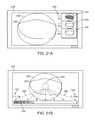
- FIGS. 2A and 2Bshow one example of a deployed tissue imager positioned against or adjacent to the tissue to be imaged and a flow of fluid, such as saline, displacing blood from within the expandable hood.
- a flow of fluidsuch as saline
- FIGS. 3A and 3Bshow examples of various visualization imagers which may be utilized within or along the imaging hood.
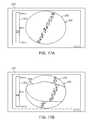
- FIGS. 4A and 4Bshow perspective and end views, respectively, of an imaging hood having at least one layer of a transparent elastomeric membrane over the distal opening of the hood.
- FIGS. 5A and 5Bshow perspective and end views, respectively, of an imaging hood which includes a membrane with an aperture defined therethrough and a plurality of additional openings defined over the membrane surrounding the aperture.
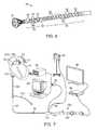
- FIG. 6shows a perspective assembly view of the steerable section of a catheter having a distal section with connected links configured to allow for multi-directional articulation, e.g., four-way articulation, and a proximal section with connected links configured to allow for articulation within a single plane, e.g., one-way articulation.
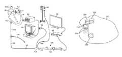
- FIG. 7illustrates an assembly view of a visualization and treatment system advanced intravascularly into a patient's heart for diagnosis and/or treatment.
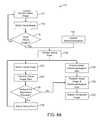
- FIG. 8Ashows a flowchart illustrating one example for synchronizing visual images of tissue with electrocardiogram data to capture images of consistent regions of tissue.
- FIG. 8Bshows an example of how visual images of tissue may be captured at coordinated intervals.
- FIGS. 9A and 9Bshow, respectively, a schematic illustration and representative graph of a tissue region undergoing ablation and the temperature differential resulting between the tissue surface and underlying tissue region.
- FIG. 9Cshows a flowchart illustrating one example for determining suitable ablation parameters for a given thickness of tissue.
- FIG. 10shows a flowchart illustrating one method for monitoring tissue temperature during ablation treatment.
- FIG. 11shows a flowchart illustrating one method for improving a contrast level of visualized tissue to improve the image clarity.
- FIGS. 12A and 12Bshow an illustrative example of a map of lesions created over a tissue region and a generated table of the corresponding parameters for each lesion.
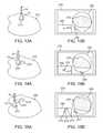
- FIGS. 13A and 13Billustrate an example of a first lesion created along a tissue region and the corresponding visual image through the hood and generated map of lesion location.
- FIGS. 14A and 14Billustrate another example of a second lesion and the corresponding visual image and generated map indicating relative lesion location.
- FIGS. 15A and 15Billustrate another example of a third lesion and the corresponding visual image and generated map again indicating relative lesion location.
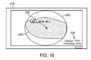
- FIG. 16illustrates a visualized image of tissue with an example of a generated informational overlay imposed upon or in proximity to the visualized image indicating certain parameters, e.g., lesion location, power levels, ablation times, etc.
- FIGS. 17A and 17Billustrate examples of a visualized region of tissue having its measured electrical potential overlaid upon the image prior to and during or after ablation.
- FIGS. 18A and 18Billustrate examples of a visualized region of tissue having its measured temperature overlaid upon the image prior to and during or after ablation.
- FIG. 19shows an example of a visualized image of region with specified informational data, such as distance from a lesion to a specified anatomical feature, overlaid upon the image.
- FIG. 20shows an example of a visualized region of tissue with specified information data, such as lesion length, overlaid upon the image.
- FIGS. 21A and 21Bshow examples of a visualized region of tissue which is treated or has been treated by formation of a lesion while images the same region is captured during the ablation process for comparison.
- FIG. 22shows an example for visually monitoring a degree of blanching of a tissue region undergoing ablation treatment.
- FIG. 23shows an example for monitoring and/or controlling a flow of saline before and/or during ablation treatment.
- FIG. 24shows an example for visually monitoring bubble formation on tissue during ablation.
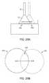
- FIGS. 25A and 25Billustrate an example of inadvertent hood movement over a tissue region and the resulting change in the visual field.
- FIGS. 26A and 26Billustrate an example of incomplete hood apposition against the tissue surface and the resulting formation of bubbles along one side of the visual field.
- Reconfiguring a tissue visualization and treatment device from a low profile delivery configuration for intravascular delivery through the vessels of a patient to a deployed and expanded configurationmay subject the distal end effector used for visualization and/or treatment, such as energy delivery, to potentially severe mechanical stresses (e.g., torsion, compression, tension, shearing, etc.).
- a reconfigurable hood which undergoes a shape change from its collapsed configuration to an expanded conical shapemay utilize a distensible, collapsible, and/or reconfigurable substrate which may utilize electrode placement and electrical connection assemblies which are robust and able to withstand such stresses.
- Such electrical connection assembliesmay be shielded or insulated from contacting other structures so as to present a smooth or unobstructive profile for reconfiguring with the hood.
- tissue-imaging and manipulation apparatusupon which one or more electrodes may be positioned and which is able to provide real-time images in vivo of tissue regions within a body lumen such as a heart, which is filled with blood flowing dynamically therethrough and is also able to provide intravascular tools and instruments for performing various procedures upon the imaged tissue regions.
- tissue-imaging and manipulation apparatusmay be utilized for many procedures, e.g., facilitating transseptal access to the left atrium, cannulating the coronary sinus, diagnosis of valve regurgitation/stenosis, valvuloplasty, atrial appendage closure, arrhythmogenic focus ablation, among other procedures.
- tissue imaging and manipulation assembly 10may be delivered intravascularly through the patient's body in a low-profile configuration via a delivery catheter or sheath 14 .
- tissue imaging and manipulation assembly 10may be delivered intravascularly through the patient's body in a low-profile configuration via a delivery catheter or sheath 14 .
- tissue imaging and manipulation assembly 10may be delivered intravascularly through the patient's body in a low-profile configuration via a delivery catheter or sheath 14 .
- tissue imaging and manipulation assembly 10may be delivered intravascularly through the patient's body in a low-profile configuration via a delivery catheter or sheath 14 .
- a transseptal procedure or septostomyTo non-operatively effect such access, one conventional approach involves puncturing the intra-atrial septum from the right atrial chamber to the left atrial chamber in a procedure commonly called a transseptal procedure or septostomy.
- imaging hood 12When the imaging and manipulation assembly 10 is ready to be utilized for imaging tissue, imaging hood 12 may be advanced relative to catheter 14 and deployed from a distal opening of catheter 14 , as shown by the arrow. Upon deployment, imaging hood 12 may be unconstrained to expand or open into a deployed imaging configuration, as shown in FIG. 1B .
- Imaging hood 12may be fabricated from a variety of pliable or conformable biocompatible material including but not limited to, e.g., polymeric, plastic, or woven materials.
- a woven materialis Kevlar® (E. I.
- imaging hood 12may be fabricated from a translucent or opaque material and in a variety of different colors to optimize or attenuate any reflected lighting from surrounding fluids or structures, i.e., anatomical or mechanical structures or instruments. In either case, imaging hood 12 may be fabricated into a uniform structure or a scaffold-supported structure, in which case a scaffold made of a shape memory alloy, such as Nitinol, or a spring steel, or plastic, etc., may be fabricated and covered with the polymeric, plastic, or woven material.
- a shape memory alloysuch as Nitinol, or a spring steel, or plastic, etc.
- imaging hood 12may comprise any of a wide variety of barriers or membrane structures, as may generally be used to localize displacement of blood or the like from a selected volume of a body lumen or heart chamber.
- a volume within an inner surface 13 of imaging hood 12will be significantly less than a volume of the hood 12 between inner surface 13 and outer surface 11 .
- Imaging hood 12may be attached at interface 24 to a deployment catheter 16 which may be translated independently of deployment catheter or sheath 14 . Attachment of interface 24 may be accomplished through any number of conventional methods.
- Deployment catheter 16may define a fluid delivery lumen 18 as well as an imaging lumen 20 within which an optical imaging fiber or assembly may be disposed for imaging tissue.
- imaging hood 12When deployed, imaging hood 12 may expand into any number of shapes, e.g., cylindrical, conical as shown, semi-spherical, etc., provided that an open area or field 26 is defined by imaging hood 12 . The open area 26 is the area within which the tissue region of interest may be imaged.
- Imaging hood 12may also define an atraumatic contact lip or edge 22 for placement or abutment against the tissue region of interest.
- the diameter of imaging hood 12 at its maximum fully deployed diameteris typically greater relative to a diameter of the deployment catheter 16 (although a diameter of contact lip or edge 22 may be made to have a smaller or equal diameter of deployment catheter 16 ).
- the contact edge diametermay range anywhere from 1 to 5 times (or even greater, as practicable) a diameter of deployment catheter 16 .
- FIG. 1Cshows an end view of the imaging hood 12 in its deployed configuration. Also shown are the contact lip or edge 22 and fluid delivery lumen 18 and imaging lumen 20 .
- deployment catheter 16may be manipulated to position deployed imaging hood 12 against or near the underlying tissue region of interest to be imaged, in this example a portion of annulus A of mitral valve MV within the left atrial chamber.
- the translucent fluid 28such as saline, may then be pumped through fluid delivery lumen 18 , intermittently or continuously, until the blood 30 is at least partially, and preferably completely, displaced from within open area 26 by fluid 28 , as shown in FIG. 2B .
- contact edge 22need not directly contact the underlying tissue, it is at least preferably brought into close proximity to the tissue such that the flow of clear fluid 28 from open area 26 may be maintained to inhibit significant backflow of blood 30 back into open area 26 .
- Contact edge 22may also be made of a soft elastomeric material such as certain soft grades of silicone or polyurethane, as typically known, to help contact edge 22 conform to an uneven or rough underlying anatomical tissue surface.
- the fluid 28may be pumped temporarily or sporadically only until a clear view of the tissue is available to be imaged and recorded, at which point the fluid flow 28 may cease and blood 30 may be allowed to seep or flow back into imaging hood 12 . This process may be repeated a number of times at the same tissue region or at multiple tissue regions.
- FIG. 3Ashows a partial cross-sectional view of an example where one or more optical fiber bundles 32 may be positioned within the catheter and within imaging hood 12 to provide direct in-line imaging of the open area within hood 12 .
- FIG. 3Bshows another example where an imaging element 34 (e.g., CCD or CMOS electronic imager) may be placed along an interior surface of imaging hood 12 to provide imaging of the open area such that the imaging element 34 is off-axis relative to a longitudinal axis of the hood 12 , as described in further detail below.
- the off-axis position of element 34may provide for direct visualization and uninhibited access by instruments from the catheter to the underlying tissue during treatment.
- the hood 12may have an open field which is uncovered and clear to provide direct tissue contact between the hood interior and the underlying tissue to effect any number of treatments upon the tissue, as described above. Yet in additional variations, imaging hood 12 may utilize other configurations. An additional variation of the imaging hood 12 is shown in the perspective and end views, respectively, of FIGS. 4A and 4B , where imaging hood 12 includes at least one layer of a transparent elastomeric membrane 40 over the distal opening of hood 12 .
- An aperture 42 having a diameter which is less than a diameter of the outer lip of imaging hood 12may be defined over the center of membrane 40 where a longitudinal axis of the hood intersects the membrane such that the interior of hood 12 remains open and in fluid communication with the environment external to hood 12 .
- aperture 42may be sized, e.g., between 1 to 2 mm or more in diameter and membrane 40 can be made from any number of transparent elastomers such as silicone, polyurethane, latex, etc. such that contacted tissue may also be visualized through membrane 40 as well as through aperture 42 .
- Aperture 42may function generally as a restricting passageway to reduce the rate of fluid out-flow from the hood 12 when the interior of the hood 12 is infused with the clear fluid through which underlying tissue regions may be visualized. Aside from restricting out-flow of clear fluid from within hood 12 , aperture 42 may also restrict external surrounding fluids from entering hood 12 too rapidly. The reduction in the rate of fluid out-flow from the hood and blood in-flow into the hood may improve visualization conditions as hood 12 may be more readily filled with transparent fluid rather than being filled by opaque blood which may obstruct direct visualization by the visualization instruments.
- aperture 42may be aligned with catheter 16 such that any instruments (e.g., piercing instruments, guidewires, tissue engagers, etc.) that are advanced into the hood interior may directly access the underlying tissue uninhibited or unrestricted for treatment through aperture 42 .
- instruments passed through catheter 16may still access the underlying tissue by simply piercing through membrane 40 .
- FIGS. 5A and 5Bshow perspective and end views, respectively, of imaging hood 12 which includes membrane 40 with aperture 42 defined therethrough, as described above.
- This variationincludes a plurality of additional openings 44 defined over membrane 40 surrounding aperture 42 .
- Additional openings 44may be uniformly sized, e.g., each less than 1 mm in diameter, to allow for the out-flow of the translucent fluid therethrough when in contact against the tissue surface.
- openings 44are illustrated as uniform in size, the openings may be varied in size and their placement may also be non-uniform or random over membrane 40 rather than uniformly positioned about aperture 42 in FIG. 5B .
- there are eight openings 44 shown in the figuresalthough fewer than eight or more than eight openings 44 may also be utilized over membrane 40 .
- various proceduresmay be accomplished.
- a procedureis crossing a tissue region such as in a transseptal procedure where a septal wall is pierced and traversed, e.g., crossing from a right atrial chamber to a left atrial chamber in a heart of a subject.
- the visualization and treatment devices described hereinmay be utilized for visualizing the tissue region to be pierced as well as monitoring the piercing and access through the tissue. Details of transseptal visualization catheters and methods for transseptal access which may be utilized with the apparatus and methods described herein are described in U.S.
- Electrodesmay be used to deliver electrical energy such as radio-frequency energy to tissue in direct contact with or in proximity to the electrodes to form lesions upon the tissue surface as well as underlying tissue regions. Additionally, the electrodes or electrode pairs may be positioned about the hood in a uniform or non-uniform manner depending upon the desired configuration. Moreover, these electrodes may also be used to deliver energy into and/or through the purging fluid which may contact the electrodes for conducting the energy through the fluid and into the underlying tissue region being treated. Alternatively, one or more of these electrodes may also be used to detect and/or measure any electrophysiological activity of the contacted tissue prior to, during, or after tissue treatment.
- hoods and tissue treatment systemsmay be utilized with the devices and methods described herein.
- the hoods, systems, and other featuresas described in Ser. No. 11/259,498 filed Oct. 25, 2005 (U.S. Pat. Pub. 2006/0184048 A1); Ser. No. 11/775,837 filed Jul. 10, 2007 (U.S. Pat. Pub. 2008/0009747 A1); Ser. No. 11/828,267 filed Jul. 25, 2007 (U.S. Pat. Pub. No. 2008/0033290 A1); Ser. No. 12/118,439 filed May 9, 2008 (U.S. Pat. Pub. 2009/0030412 A1); Ser. No.
- such assemblies, apparatus, and methodsmay be utilized for treatment of various conditions, e.g., arrhythmias, through ablation under direct visualization. Details of examples for the treatment of arrhythmias under direct visualization which may be utilized with apparatus and methods described herein are described, for example, in U.S. patent application Ser. No. 11/775,819 filed Jul. 10, 2007 (U.S. Pat. Pub. No. 2008/0015569 A1), which is incorporated herein by reference in its entirety.
- Variations of the tissue imaging and manipulation apparatusmay be configured to facilitate the application of bipolar energy delivery, such as radio-frequency (RF) ablation, to an underlying target tissue for treatment in a controlled manner while directly visualizing the tissue during the bipolar ablation process as well as confirming (visually and otherwise) appropriate treatment thereafter.
- bipolar energy deliverysuch as radio-frequency (RF) ablation
- an articulatable deployment catheter 50which comprises a distal steerable section 52 and a proximal steerable section 54 located proximally of the distal steerable section 52 .
- Further details of the deployment catheter 50which may be used herein may be seen in further detail in U.S. patent application Ser. No. 12/108,812 filed Apr. 24, 2008 (U.S. Pat. Pub. No. 2008/0275300 A1), which is incorporated herein by reference in its entirety.
- An intervening link 56may couple the sections 52 , 54 to one another and provide a terminal link to which one or more pull wires may be attached in controlling one or both sections.
- the distal steerable section 52may utilize individual links 66 which allow for the section 52 to be articulated in a variety of different directions and angles, e.g., four-way steering, to enable omni-direction articulation.
- the individual links 66may accordingly utilize a body member 68 having a pair of yoke members 70 positioned opposite to one another and extending distally from the body member 68 and each defining an opening.
- a pair of pins 72may each extend radially in opposing directions from body member 68 and in a perpendicular plane relative to a plane defined by the yoke members 70 .
- each link 66may be pivotably received by the yoke members 70 of an adjacent link 66 such that the pins 72 and yoke members 70 are joined in an alternating manner. This alternating connection allows for the serially aligned links 66 to be articulated omni-directionally.
- the links 58 of the proximal steering section 54may also comprise a pair of yoke members 62 positioned opposite to one another and extending distally from body member 60 . However, the pins 64 may extend radially in opposing directions while remaining in the same plane as that defined by yoke members 62 . When joined together in series, each pin 64 of each link 58 may be pivotably received by the yoke members 62 of an adjacent link 58 . Yet when joined, the composite proximal steering section 54 may be constrained to bend planarly within a single plane relative to the rest of the deployment catheter.
- the combined distal steerable section 52 and a proximal steerable section 54results in a proximal steering section which can be articulated in a single plane to retroflex the entire distal assembly and a distal steering section which can then be articulated any number of directions, e.g., four-way steering, to access anatomical structures within the heart or any other lumen.
- the assemblymay thus be used, e.g., to create circumferential lesions around the ostia of the pulmonary veins in the left atrium while the underlying tissue remains under direct visualization through the hood.
- FIG. 7shows an illustrative assembly of how a visualization catheter system may be configured and advanced intravascularly within a patient. Further details of the system which may be used herein may be seen in further detail in U.S. patent application Ser. No. 12/323,281 filed Nov. 25, 2008 (U.S. Pat. Pub. No. 2009/0143640 A1), which is incorporated herein by reference in its entirety.
- FIG. 7illustrates a perspective assembly view of an endoscope 108 introduced within seal 94 and deployment catheter 88 .
- Hood 12can be first collapsed by hood retraction control 98 while saline is purged through hood 12 to ensure no bubbles are trapped inside hood 12 .
- Catheter 88may be advanced within introducer sheath 106 for deployment within the patient body.
- introducer sheath 106may further include a fluid irrigation port 104 extending from sheath 106 for coupling to a fluid reservoir or for providing access to other instruments into the patient body.
- the variation shownalso illustrates an example where an additional endoscope handle interface may be attached to hub 100 for facilitating coupling and de-coupling to endoscope handle 102 .
- Hood 12 and deployment catheter 88may be advanced through introducer sheath 106 into the patient's vasculature, e.g., through the inferior vena cava IVC and transseptally into the left atrium LA of the patient's heart H, where tissue regions may be treated, such as lesion creation around the ostia of the pulmonary veins for treatment of atrial fibrillation.
- tissue regionsmay be treated, such as lesion creation around the ostia of the pulmonary veins for treatment of atrial fibrillation.
- hood 12Once hood 12 has been advanced into the left atrium LA, hood 12 may be deployed to expand for visualization and tissue treatment.
- Hood 12may be purged via saline fluid from reservoir 82 introduced through port 96 while an electrode assembly along hood 12 may be utilized to detect, e.g., ECG signals 90 , or to ablate tissue via generator 80 .
- Electrodes assemblymay be electrically coupled through catheter 88 to a processor and/or video display, e.g., electrocardiogram (ECG) display, via junction 92 , which may also be electrically coupled to generator 80 for providing power, e.g., RF energy, to the electrode assembly.
- ECGelectrocardiogram
- the underlying tissuemay be visualized via the endoscope imaging assembly which may in turn be coupled to video processor assembly 84 which may capture and process the detected images within hood 12 for display upon monitor 86 .
- hood 12may be purged via fluid introduced through a fluid lumen defined through the endoscope itself.
- the working channel of the endoscope and/or irrigation portcan also be used to introduce guidewires, needles (such as transseptal or biologics delivery needles), dilators, ablation catheters (such as RF, cryo, ultrasound, laser and microwave), temperature monitoring probes, PFO closure devices, LAA closure implants, coronary artery stents, or other implantable devices or tools for performing diagnosis and/or treatment of the imaged target tissue.
- needlessuch as transseptal or biologics delivery needles
- ablation catheterssuch as RF, cryo, ultrasound, laser and microwave
- temperature monitoring probessuch as RF, cryo, ultrasound, laser and microwave
- PFO closure devicessuch as RF, cryo, ultrasound, laser and microwave
- temperature monitoring probessuch as RF, cryo, ultrasound, laser and microwave
- PFO closure devicessuch as RF, cryo, ultrasound, laser and microwave
- temperature monitoring probessuch as RF, cryo, ultrasound, laser and microwave
- PFO closure devicessuch as RF, cryo, ultrasound,
- tissue regions within the body to be visualized and/or treatedmay undergo occasional or constant movement in vivo.
- organssuch as the lungs constantly expand and contract while the patient undergoes respiration and other organs such as the heart constantly contract to pump blood through the body.
- acquiring a tissue image and/or other physiologic data taken at a first instancemay present a condition which is inconsistent with the tissue image and/or physiologic data taken at a second instance.
- tissue regionbeing able to acquire images and/or physiologic data of a particular tissue region at a first point during tissue movement and at additional points during subsequent tissue movements taken consistently when the tissue is similarly situated may present a more accurate representation of the condition for evaluation of the tissue region being examined and/or treated.
- tissue regionlocated within an atrial chamber within the beating heart
- methodsmay be utilized to minimize the effect of this movement on obtained data.
- One methodmay involve gating the acquisition of the tissue images and/or corresponding data by utilizing a reference signal produced by the body for coordinating the corresponding acquisition of information.
- the acquisition of the informationmay be triggered by a sensed event, e.g., the QRS complex recorded from a single heartbeat of the electrocardiogram (ECG) which corresponds to a depolarization of the right and left ventricles.
- ECGelectrocardiogram
- gated acquisitionmay also be utilized herein.
- gated acquisitionmay also be utilized for obtaining images and/or other data based on chest-wall motion for respiratory-gated acquisition of data.
- Another method formay involve retrospective gating of the data where information, such as visual images and/or other physiologic data, may be acquired continuously from the tissue region. This allows for the capturing of information over several cycles of the organ or tissue region of interest. By calculating or determining a timing delay within the captured data, the information can be reconstructed at one or more specified points over many heart beats relative to a predetermined reference or triggering signal. This may allow for a “snapshot” of the heart to be reconstructed at a specific phase within the cardiac cycle with the information for this “snapshot” acquired over several beating cycles which may or may not have occurred at regular intervals.
- CT images of the heartmay be captured in synchronization with a sensed ECG signal such that all the CT image slices are generated at the same point during the heart cycle.
- the three-dimensional imagesmay be blurred rendering them unsuitable for analysis.
- images of the organsmay also be synchronized with the respiratory cycle, as previously mentioned.
- anatomical features, electro-anatomical maps, or any other real-time datais to be registered against real-time visual images of the heart or any other moving organ
- a determination of which cycle the image was acquiredmay be used to achieve proper registration between the data and the corresponding image.
- one or more visual imagesmay be collected simultaneously with the sensed ECG data.
- An example for synchronizing data, in this case ECG data, with real-time visual imagesis illustrated in the flowchart 110 , as shown in FIG. 8A .
- the hood 12may be advanced intravascularly, e.g., into a heart chamber such as the left atrial chamber, where it may be presented against a tissue region of interest moving as the heart continues to beat.
- the hood 12may be cleared, as previously described, and one or more images of the underlying tissue may be acquired 112 .
- These one or more imagesmay be buffered 114 and multiple images may be acquired 116 until sufficient images are captured.
- a gating pointmay be selected 120 such as during an R wave of the QRS Complex, although any number of other physiologic triggering points may be utilized.
- a controller or processormay select the appropriate visual image 122 which was captured correspondingly and transmit the visual image data 124 for comparison. The controller or processor may then adjust the gating point 126 , if necessary, in which case the gating point may be appropriately adjusted 134 by selecting another appropriate image.
- a new set of corresponding visual imagesmay be displayed.
- Such synchronizationmay allow for visual analysis of the tissue that is imaged as the impact on the image quality due to the movement of the tissue may be greatly reduced (for example, due to the expansion and contraction of the heart).
- the recorded ECG datamay be extracted 128 and the data may be registered with the corresponding visual image 130 .
- the final extracted image with the corresponding ECG datamay then be displayed as a composite image 132 to the user.
- a detected and recorded ECG measurement 140 of a patientis shown and displayed over several cycles of the heart beating. While the ECG measurement 140 was recorded, the visual images of the tissue region of interest were simultaneously captured as well.
- the visual images of the tissue region captured at those corresponding timesmay be extracted and registered corresponding to each gating point. The image at each gating point may then be displayed to the user as a composite image, as shown.
- the first gating point 142 shown on the ECG measurement 140may have a first corresponding image 150 displayed accordingly and the second gating point 144 may have a second corresponding image 152 displayed accordingly as well.
- third gating point 146may have third corresponding image 154 displayed while fourth gating point 148 may have fourth corresponding image 156 displayed, and so on.
- the visualized tissue regionmay be compared between captured images to provide a more accurate representation of the tissue in any particular state.
- cardiac-gating of informationallows for piece-wise data acquisition over multiple heart beats to create a global view of the heart at a single phase within the cardiac cycle.
- the end-systolic phase of the cardiac cyclerepresents the maximum contraction of the ventricle. Therefore, the ventricular cavity defines its relative smallest volume at this phase of the cardiac cycle.
- the end-diastolic phase of the cardiac cyclerepresents the end of the filling period of the left ventricle with blood. The ventricle is at its maximum or near-maximum volume at this phase.
- mapping pointsmay include the relative position (e.g., X, Y, Z coordinates) to be consistently captured at the point during the cardiac cycle relative to the reference or gating signal, such as the ECG signal.
- the reference or gating signalsuch as the ECG signal.
- one physiologic characteristic which is usually not readily available to physiciansis the thickness of the tissue at a desired lesion location. It may be generally useful to know the thickness of the tissue in facilitating lesion formation by applying an appropriate level of energy to prevent excessive lesion formation (e.g., lesions which are larger and/or deeper than desired) in order to prevent damage to surrounding tissue or anatomy. Information on the tissue thickness may also be useful to the physician so that the optimal parameters for ablation may be determined with respect to the speed of the ablation formation to safely reduce procedural time.
- FIG. 9Aillustrates an example of hood 12 placed against a tissue region T to be ablated.
- a temperature differentialis formed between the tissue surface T 1 and a region of underlying tissue T 2 .
- tissue surface T 1may undergo ablation first as its temperature rises quickly during ablation treatment, as indicated by curve 162 , relative to the temperature of the underlying tissue T 2 which rises slowly over time, as indicated by curve 164 , shown in the ablation time versus temperature graph 160 of FIG. 9B .
- tissue thicknessmay be detected 174 utilizing, e.g., hood 12 having one or more ultrasonic transducers positioned upon hood 12 or its distal membrane in contact with the underlying tissue.
- the tissue thicknessmay be detected 174 utilizing, e.g., hood 12 having one or more ultrasonic transducers positioned upon hood 12 or its distal membrane in contact with the underlying tissue.
- the one or more transducersmay be placed against the tissue surface to be treated and ultrasonic signals may be emitted into the tissue.
- the emitted signalsmay be reflected by any underlying obstructions or tissue interfaces such that the return signals received by the transducer or receiver may be automatically processed by a processor to analyze the return signals for peaks of the ultrasonic waves received and the time intervals between them to determine a thickness of the underlying tissue.
- tissue thicknessmay also be determined by, e.g., sensor triangulation techniques, trans-esophageal echocardiography or any other methods.
- a nominal tissue thicknessmay be programmed into a processor by the user to set a threshold tissue thickness for safely performing tissue ablation.
- the detected tissue thicknessmay then be compared against this nominal thickness threshold 176 .
- the controllermay automatically determine the appropriate ablation parameters suitable for this detected thickness 178 such as, power levels (e.g., Watts), flow rate of the purging/conductive fluid through the hood (e.g., cc/min), ablation treatment times (e.g., sec), etc. (which may be available on a table of tissue depth versus power, flow rate, ablation duration, etc.).
- This determinationmay be performed automatically by the system or by the user and ablation may be started 180 either automatically or initiated by the user.
- the systemmay alert the user 182 who may then re-measure the tissue thickness 184 . If the re-measured tissue thickness exceeds the nominal tissue thickness, ablation may proceed, as previously described, or the operator may determine the ablation parameters manually 186 and then initiate ablation 180 .
- tissue thickness and ablation parametersit may be also useful to monitor the temperature of the tissue surface during the ablative process.
- Ablation of tissueis typically performed such that it causes irreversible tissue damage to selected regions of tissue.
- the temperature at which irreversible tissue damage typically occursis around 53° C. depending on the tissue thickness. Excessively high temperatures may give rise to the possibility of bubble formation on the tissue (which may pop as steam) or tissue charring. Steam pops, which may burst with an audible popping sound, may disrupt the myocardium and cause perforations on the tissue surface potentially leading to complications, such as cardiac tamponade, which may cause the heart to pump decreasing amount of blood.
- Charring of tissuemay also allow thrombus formation which may embolize and potentially lead to stroke, ischemia, and/or myocardial infarction among other things.
- the tissue temperaturemay be initially measured 194 utilizing any number of temperature measurement devices.
- temperature sensorsmay be positioned along the hood 12 and/or distal membrane of the hood in contact against the tissue surface.
- Other sensorsmay include, e.g., thermocouples, thermistors, fluoro-optic temperature sensors, thermochromic markers under direct visualization through the hood 12 , etc.
- Thermochromic markersmay be embedded within the distal membrane which may be pressed against the tissue region.
- Changes in the marker colors which are indicative of the tissue temperature changesmay be monitored through hood 12 via the imager or via an automated vision sensing system. Further examples of tissue temperature sensors and methods of their use are described in further detail in U.S. patent application Ser. No. 12/118,439, which is incorporated herein by reference above.
- needle probes or similar devicesmay be inserted into the tissue region to be treated to provide a measurement of the sub-surface tissue temperature.
- FIG. 10Further examples of sub-surface measurement systems and methods of their use which may be utilized with the devices and methods described herein are shown in further detail in U.S. patent application Ser. No. 11/775,837 filed Jul. 10, 2007 (U.S. Pat. Pub. 2008/0009747 A1), which is incorporated herein by reference in its entirety.
- T High and/or lower T Low limits for the allowed temperature rangeare set 196 to ensure adequate power delivery for therapy yet prevent unwanted complications due to excessive (or inadequate) energy delivery.
- the tissuemay then be ablated 198 while the tissue temperature (surface and/or sub-surface) is monitored. So long as the monitored tissue temperature remains above the preset lower T Low temperature limit 200 , ablation may continue 202 unabated.
- an audible or visible indicatormay notify the user and/or a controller may pause the ablation 208 . Attention by the user may allow for adjustment of the ablation treatment and/or preset temperature limits.
- ablationmay continue until the procedure is completed 210 and ablation treatment may be stopped 212 .
- an audible or visible indicatormay notify the user and/or a controller may pause the ablation 206 . Attention by the user may allow for adjustment of the ablation treatment and/or preset temperature limits 210 so either allow for continued ablation treatment 202 or cessation of ablation 212 .
- One method for improving the visual images of the imaged tissue for assessment by the usermay include adjusting the contrast of the captured images. Contrast allows for different tissue regions to be distinguished visually from one another within an image or video. Digital imaging systems such as CMOS image sensors or CCD camera systems have light sensitivities which vary with the wavelength of light. Thus, altering the chromaticity or color of illumination used during imaging could emphasize or de-emphasize certain colors within the imaged field or the change in illumination color composition could target the sensitivity of the image sensor.
- FIG. 11shows an example for improving image contrast prior to and/or during tissue ablation in flowchart 220 .
- a methodmay be utilized while visually observing tissue ablation through hood 12 via the imager to improve contrast and differentiation between regions of, e.g., normal myocardial tissue and regions where ablation lesions have been created for the treatment of cardiac arrhythmias such as atrial fibrillation.
- images acquired from the field of view through hood 12may have their contrast levels and other relevant characteristics determined and then compared to previously stored data.
- a processormay be used to increment various illumination color channels (such as the brightness of different color LED light sources which combine to provide the illumination).
- the processormay re-evaluate the contrast levels and continue to adjust the color balance of the illumination source. If additional changes in contrast are determined to be unnecessary or differences in contrast are nominal or eliminated between comparisons, the processor may evaluate the output image with respect to the range limits of this system.
- the images of the tissue region of interestmay be captured while the system begins in a default mode 222 .
- the RGB (red, green, blue) values of the imagesmay be acquired 224 and determined by a processor and then optionally converted to an HSV (hue, saturation, value) color model (or other color space) 226 to more accurately describe the perceptual color relationships.
- HSVhue, saturation, value
- the newly obtained images with their RGB or HSV valuesmay then be compared and contrasted to a previously obtained frame or stored frame 228 via the processor.
- the RGB values in the light source illuminating the tissue regionmay be increased incrementally and sequentially 232 by the processor and the entire process repeated until the contrast levels are equivalent between previously obtained images and newly obtained images 230 .
- the RGB or HSV valuesmay be compared against predetermined range limits 234 by the processor.
- a comparison of the images against the range limitsmay yield RGB values which exceed these limits 236 , in which case the images and/or range limits may be reset and the processor may perform a diagnostic test on the system 238 and an indication or warning may alert 240 the user. Otherwise, if the images against the range limits yield RGB values which are within the limits, then the contrast levels and light settings may be recorded 242 and the RGB light source may be set to these values 244 and the visualization assessment or procedure may proceed 246 .
- tissue region 250which can vary physiologically depending upon which region is treated.
- the usermay automatically track the parameters and locations which may be unique for each of the lesions formed over tissue region 250 , as shown in FIG. 12A .
- the table in FIG. 12Bshows an example of how a processor in communication with the visualization and/or treatment device may catalogue and identify each formed lesion utilizing visual information captured from the field of view through the hood 12 .
- the unique shape of each lesionmay be used to determine the “address” of that particular lesion.
- An edge finding, texture classification, or morphology algorithmmay be used to determine the outline, surface pattern, or shape of the lesion from the visual information provided by the visualization device. This information and/or an image depicting the ablation lesion is then constructed into an array and tagged with the appropriate data such as the RF power and the length of time ablation took place to create the particular lesion.
- first lesion 252may be identified by its unique shape and/or relative location and its corresponding power level and ablation time may be identified on the array.
- each subsequent lesione.g., second lesion 254 , third lesion 256 , fourth lesion 258 , fifth lesion 260 , etc. may have its own power level and ablation time associated accordingly.
- lesion identificationmay be accomplished via the usage of color comparison algorithms and/or biological markers on the lesions among other identifiers. This information may be particularly useful for re-identification, comparison and mapping of all lesions on the tissue surface 250 . If catheter position information is available, this information may be combined with the data of the array of FIG. 12B to automatically map out the ablation lesions relative to their position within the heart.
- a navigational mini-mapmay be utilized which allows the physician to view, track and/or map the multiple lesions that are formed on the tissue surface during the ablative treatment.
- lesionsmay be detected and/or their relative location to one another may be determined by various methods, such as measuring optical flow as the hood of the catheter moves from one site to another. This information may be then displayed on a map on the monitor 278 .
- a first lesion 272may be seen on the tissue region 270 in FIG. 13A with the lesion 272 as seen through the hood 12 in the corresponding field of view 282 .
- the location of the first lesion 272may accordingly be registered and illustrated, e.g., on image 280 of display 278 , as shown in FIG. 13B .
- a directional movement indicatormay be superimposed to point in a first direction 284 on the monitor 278 to indicate a direction in which the catheter hood 12 is moving (or is to be moved) relative to the tissue surface 270 and/or other lesions.
- FIG. 14Ashows the position of a second lesion 274 which has been formed (or is to be formed) on the tissue surface 270 .
- Image 280may illustrate the position of the second lesion 274 relative to the first lesion 272 and the field of view 282 may show the visual image of the lesion 274 itself, as shown in FIG. 14B .
- the directional indicatormay indicate a second direction 284 ′ in which the hood 12 is moving (or is to be moved) to reach the location of the third lesion 276 which is either formed or to be formed.
- FIG. 15Ashows the position of a third lesion 276 relative to the first 272 and second 274 lesions while image 280 may reflect the relative positioning on monitor 278 .
- Third lesion 276may be shown in the field of view 282 while the directional indicator may point to yet another direction 284 ′′ in which hood 12 may be moved for lesion visualization and/or formation, as shown in FIG. 15B .
- FIG. 16When providing real-time visual images for the purposes of tissue diagnosis or treatment, it may be useful to overlay relevant information to aid the physician during diagnosis and/or treatment.
- an overlayis shown in the monitor 278 of FIG. 16 which illustratively shows the field of view 282 as seen through hood 12 with lesion 290 previously or recently formed.
- Any number of physiologic or treatment parametersmay be overlaid directly upon the monitor 278 for display to the user to facilitate assessment or treatment, e.g., for estimating the depth of the lesion formed.
- treatment information 292e.g., positional information, applied power levels, time of ablation treatment, etc.
- Any other additional information 294e.g., applied voltage, tissue thickness, etc.
- Electrodes positioned along the hoodmay be used to measure the electrical potential (such as the bipolar voltage amplitude or monopolar voltage amplitude relative to a reference catheter or Wilson central terminal) of points on a tissue surface. Further examples of electrodes positioned along the hood and/or distal membrane which may be utilized herein are described in detail in U.S. patent application Ser. No. 12/118,439, which is incorporated herein by reference above.
- FIG. 17Ashows a monitor view of measured gradient of electric potential 300 of the tissue overlaid upon the visualized tissue region seen in the field of view 282 through hood 12 .
- An electrical potential indication chart 302may be seen also on monitor 278 to indicate the level of detected electrical potential for reference by the user.
- the measured electric potential at the region of the lesion 304may be monitored and overlaid atop the visualized lesion.
- a threshold value of electrical potentialmay be optionally preset by the user such that if the measured electrical potential of the lesion is reduced during ablation, e.g., ⁇ 0.5 mV bipolar voltage, then an indicator may alert the user that the lesion has been successfully electrically isolated from the surrounding tissue. This may facilitate physician assessment as to when lesion formation is complete.
- FIG. 18Aillustrates an example where the temperature gradient 310 of the visualized tissue may be measured and superimposed upon the visualized tissue utilizing temperature sensors, as described in further detail in U.S. patent application Ser. No. 12/118,439, which is incorporated herein by reference above.
- a temperature indication chart 312may be shown along the monitor 278 for reference by the user.
- ablationmay be controlled such that the tissue remains within prescribed temperature limits. Overlaying the temperature information of the lesion 314 as it is being formed may assist the physician, e.g., in assessing whether to terminate the ablation should a localized hot spot develop on the tissue surface, as shown in FIG. 18B .
- an informational overlay which may facilitate tissue treatment assessmentmay incorporate the distance of a tissue region to be treated (or undergoing treatment) to a predetermined anatomical object or location.
- ablation of heart tissuetypically occurs near the location of the esophagus, which lies very close to and often touches the outer wall of the left atrium, within the body.
- the heat from the ablation proceduremay penetrate through the tissue of the left atrium and reach the esophagus. Uncontrolled ablation may thus present a risk as lesions may be formed which extend towards or in proximity to the esophagus thus potentially damaging the esophageal tissue.
- mapping catheters and other imaging methodssuch as use of swallowed contrast agents or probes to indicate either the pre-operative or real-time position of the esophagus may be used.
- some physicianshave used standard mapping catheters to record the pre-procedure location of the esophagus.
- a pre-procedure location determinationfails to account for the mobile nature of the esophagus.
- the esophagusgenerally does not remain stationary. Rather, the esophagus often moves back and forth thereby positioning itself in different locations relative to the heart wall. As such, the esophagus may change its location during a catheter-based endocardial procedure.
- the pre-procedure determinationfails to account for this movement. Accordingly, displaying information in real-time such as the proximity of the ablation catheter to the probe on the monitor 278 may facilitate such treatments, as shown in FIG. 19 , which shows lesion 320 and distance information to a preselected object 322 , such as the esophagus. Moreover, a directional indicator to the object 324 may also be imposed on monitor 278 to indicate to the user the relative direction to the object.
- Non-limiting examples of suitable analysis techniques for determining distance for use with the system, devices, and methods described hereinmay include impedance measurement, pacing signal amplitude measurement, use of magnetic fields, use of Hall effect sensors, inductance measurement, capacitance measurement, etc.
- a physicianmay continuously monitor throughout an entire mapping and/or ablation procedure the position of the object, such as the esophagus, relative to the device in use in the heart. This continuous, real time monitoring of the location of the esophagus may further accounts for the movement of the esophagus to decrease the risk of damage to the esophagus. Additional examples which may be utilized herein are further described in detail in U.S. Pat. Pub. 2007/0106287 A1, which is incorporated herein by reference in its entirety.
- FIG. 20illustrates an example of how distances 332 between two selected points may be measured directly on the monitor 278 to provide metric information 330 such as the length of a particular lesion.
- Such overlaysmay be utilized to determine, e.g., the surface size of the lesion precisely to facilitate physician assessment of lesion size. It may also be used to accurately measure anatomical features in the body. Typically, a reticule of a known distance may be included within the field of view which would allow for calibration of the measurement to a know distance. The accuracy of this measurement would be highest for objects that are in the same plane as the calibration distance. Further examples of measuring tissue regions in vivo which may be used herein with the devices and methods are shown and described in detail in U.S. Ser. No. 12/118,439 filed May 9, 2008, which is incorporated herein by reference in its entirety.
- Tissue colormay be used as a good indicator of the stage of completion of the lesion forming process as normal, unablated myocardial tissue is characteristically pink or red in color.
- Tissue colormay be used as a good indicator of the stage of completion of the lesion forming process as normal, unablated myocardial tissue is characteristically pink or red in color.
- the lesion sitewill change color due to heating, dessication, denaturation of proteins, and/or ischemia.
- the lesion sitewill typically become white and then possibly black, brown, or yellow as ablation continues if applied beyond the usual limits.
- real-time visualization and ablationit may become difficult to distinguish the degree of color change that has taken place due to the graduated nature of the color change.
- FIG. 21AAn example of monitoring color changes in tissue during ablation treatment is illustrated in FIG. 21A , which shows an overlay of multiple images of the tissue surface at preselected time intervals as ablation progresses from, e.g., 10 secs to 60 secs.
- the time intervals at which the captured images may be selected for viewingmay be selected at relatively higher or lower sampling rates.
- images of lesion 320may be captured, e.g., at a recorded ablation time 340 of 10 sec, 30 sec, and 60 sec with a first corresponding image 342 , second corresponding image 344 , and third corresponding image 346 showing the progression of the tissue coloring from a pink or red state eventually to a blanched condition. Having these images simultaneously displayed may provide contextual information to the user in determining whether sufficient ablation had occurred in the tissue being treated.
- FIG. 21Billustrates monitor 278 showing a particular measured region 348 of lesion 320 tracked and imaged over a period of time from a first measured ablation time 352 to a final measured ablation time 354 , e.g., from 10 sec to 60 sec.
- a temperature chart 350may be provided illustrating the eventual change in tissue color as ablation progresses through the ablation treatment.
- One or more indicatorsmay show the tissue coloring at a corresponding ablation time, e.g., from a first corresponding tissue image 356 to a final corresponding tissue image 358 , which may be available to the user for assessment.
- the degree of blanchingmay be determined by a number of different methods. Blanching occurs as a result of heating a tissue region which causes proteins to denature and desiccate. This eliminates blood flow from the tissue hence turning it from a pink or red color to a white color. Thus, blanching of tissue may serve as a visual indicator of ablated tissue.
- FIG. 22illustrates how certain tissue characteristics may be monitored.
- a processor in communication with the imagermay monitor a histogram of color channels of the tissue being visualized 366 and the processor may then determine a rate of change of the color histogram 368 . If the rate of change is determined by the processor to be higher than a preset limit, this may be an indication that the tissue is blanching at a higher rate than desired and the processor may continue to monitor the tissue color change. Otherwise, if the rate of color change is lower than the preset limit, then the processor may determine the degree of surface reflectance 370 .
- the processorindicates that the surface reflectance is higher than a preset value, then the color may continue to be monitored otherwise if the reflectance is lower than the preset value, a determination may be made as to whether there is any appearance of particular colors from the tissue which may indicate that ablation of the tissue is nearing completion, e.g., white, brown, yellow, black, etc. 372 . If the processor does detect the appearance of any of these particular colors, an audible or visual indicator may notify the physician 374 and ablation may be stopped automatically by the processor or directly by the physician 376 .
- a processormay control the flow of the purging fluid which may also be used to conduct a current to the tissue to be treated.
- flowchart 380shows an example where the color change of the lesion may also be utilized for controlling or altering the purging fluid flow through the hood and over the tissue region being visualized and/or treated. It is generally desirable to deliver the lowest amount of saline to the patient through the hood 12 as an excessive flow of saline may cause the balance of electrolytes in the body to fluctuate potentially resulting in hyponatremia.
- the saline fluidmay be introduced into hood 12 to begin purging of the blood within the hood and to clear the visualization field 384 .
- This fluidmay be introduced at an initial predetermined rate and registering of the RGB ratio of the imaged underlying tissue may begin 386 , as described above.
- the processordetermines that the detected RGB color channels are increasing at a desirable preset rate in approaching a predefined boundary (utilizing parameters such as hue, saturation, etc.) 388 , then the percentage of the color red may be determined for the captured image 392 and if the this percentage is above a predetermined level, then this is an indication that the visual field is sufficiently clearing of blood. However, if the RGB color channels are determined not to be increasing at a desirable rate, then the processor may automatically increase a flow rate 390 of the saline into the hood 12 to increase the rate at which blood is cleared. Likewise, if the percentage of the detected color red is found to be below the predetermined level, then monitoring of the color may be continued until the blood is sufficiently cleared from the visual field of hood 12 .
- the saline flow ratemay be reduced to a predetermined level 394 , e.g., defined by the physician or active recirculation of the saline may be produced within the hood.
- a determinationmay then be made as to whether to maintain the flow optimization 396 in which case if flow optimization is continued, then the color change within the hood may be continued to be monitored. Otherwise, the flow control may be terminated 398 .
- FIG. 24illustrates a flowchart 400 which shows one method for utilizing bubble detection where the process may begin 402 by acquiring the visual image 404 , as previously described.
- the visual imagemay be processed by a processor to find locations of any “hotspots” 406 , i.e., areas of high reflection, which may be indicative of the presence of bubbles.
- the visual fieldmay then be searched for potentially spherical objects 408 and further monitored to determine whether a radius or diameter of any spherical objects are growing 410 during the ablation process. In the event that the detected radius is not any larger than a preset limit 412 , then the process of searching may continue 414 . Otherwise, if the radius is determined to exceed the preset limit, then the bubble diameter may continue to be monitored over time 416 .
- the processormay then determine whether the number of detected bubbles in the visual field exceed a threshold value 418 . In the event that the number of detected bubbles are insufficient, the physician may be notified and/or the power level may be maintained or increased 420 and the visual field may be continued to be monitored for the formation of bubbles. Otherwise, if the number of detected bubbles exceed the threshold number, then an alert may notify the physician and/or the system may power down automatically and/or the flow rate may be increased to cool the tissue region down in temperature 422 .
- the systemthen alerts the physician to take a measure of corrective actions which may include increasing the saline flow rate or powering down the system among other things. Bubbles may be difficult to detect with the naked eye, hence this protocol may be useful in alerting physicians immediately upon the presence of even tiny bubbles.
- the various protocols or methods disclosedmay be used in any combination for processing the visual images generated. Additionally the overlays disclosed may be used in any combination as well to provide users with one or more layers of information.
- FIGS. 25A and 25Billustrate side and plan views of a hood 12 which is placed into contact against a tissue region T to be visualized and/or treated.
- hood 12may be inadvertently shifted from a first location 430 to a second location 432 over the tissue surface, as indicated respectively by two points labeled A and B.
- the region being visualizedmay move continually making it difficult to observe the tissue or to perform any procedures upon the tissue.
- Such movementcan be monitored visually by several methods such that the user is able to determine an appropriate time to begin a procedure.
- the overlap region 434may be calculated between the first location 430 and second location 432 compared against a threshold limit. With the distance of hood movement known, a procedure may be initiated and/or stopped appropriate each time the hood 12 is expected to move such that treatment may be synchronized according to hood and tissue movement.
- FIGS. 26A and 26Bshow side and monitor views of a hood 12 which is insufficiently apposed against the surface of a tissue region T to be visualized and/or treated. As it may be difficult to determine if the hood 12 is seated perpendicularly on the tissue surface or is in an off-axis configuration, it may be possible to detect and correct for such off-axis alignment from the tissue by processing of the visual images.
- hood 12is not placed into direct apposition against the tissue surface, gases introduced into hood 12 along with the purging fluid may form along the side of hood 12 which is not in contact with the tissue, i.e., bubbles 440 may form along a gap or spacing 442 between hood 12 and the tissue surface. These bubbles 440 may be visible in the field of view 282 and thus alert the user that the hood 12 positioning along the tissue may require readjustment.
Landscapes
- Health & Medical Sciences (AREA)
- Life Sciences & Earth Sciences (AREA)
- Engineering & Computer Science (AREA)
- Surgery (AREA)
- Veterinary Medicine (AREA)
- General Health & Medical Sciences (AREA)
- Physics & Mathematics (AREA)
- Animal Behavior & Ethology (AREA)
- Public Health (AREA)
- Molecular Biology (AREA)
- Biomedical Technology (AREA)
- Heart & Thoracic Surgery (AREA)
- Medical Informatics (AREA)
- Pathology (AREA)
- Biophysics (AREA)
- Cardiology (AREA)
- Nuclear Medicine, Radiotherapy & Molecular Imaging (AREA)
- Physiology (AREA)
- Signal Processing (AREA)
- Optics & Photonics (AREA)
- Artificial Intelligence (AREA)
- Computer Vision & Pattern Recognition (AREA)
- Psychiatry (AREA)
- Radiology & Medical Imaging (AREA)
- Plasma & Fusion (AREA)
- Otolaryngology (AREA)
- Surgical Instruments (AREA)
Abstract
Description
Claims (8)
Priority Applications (3)
| Application Number | Priority Date | Filing Date | Title |
|---|---|---|---|
| US12/618,306US9468364B2 (en) | 2008-11-14 | 2009-11-13 | Intravascular catheter with hood and image processing systems |
| US15/283,812US11622689B2 (en) | 2008-11-14 | 2016-10-03 | Mapping and real-time imaging a plurality of ablation lesions with registered ablation parameters received from treatment device |
| US18/166,589US12433490B2 (en) | 2008-11-14 | 2023-02-09 | Ablation and imaging catheter with user interface to catalogue ablation parameters and identification labels for lesions |
Applications Claiming Priority (2)
| Application Number | Priority Date | Filing Date | Title |
|---|---|---|---|
| US11483408P | 2008-11-14 | 2008-11-14 | |
| US12/618,306US9468364B2 (en) | 2008-11-14 | 2009-11-13 | Intravascular catheter with hood and image processing systems |
Related Child Applications (1)
| Application Number | Title | Priority Date | Filing Date |
|---|---|---|---|
| US15/283,812ContinuationUS11622689B2 (en) | 2008-11-14 | 2016-10-03 | Mapping and real-time imaging a plurality of ablation lesions with registered ablation parameters received from treatment device |
Publications (2)
| Publication Number | Publication Date |
|---|---|
| US20100130836A1 US20100130836A1 (en) | 2010-05-27 |
| US9468364B2true US9468364B2 (en) | 2016-10-18 |
Family
ID=42196946
Family Applications (3)
| Application Number | Title | Priority Date | Filing Date |
|---|---|---|---|
| US12/618,306Active2032-06-30US9468364B2 (en) | 2008-11-14 | 2009-11-13 | Intravascular catheter with hood and image processing systems |
| US15/283,812Active2032-03-01US11622689B2 (en) | 2008-11-14 | 2016-10-03 | Mapping and real-time imaging a plurality of ablation lesions with registered ablation parameters received from treatment device |
| US18/166,589ActiveUS12433490B2 (en) | 2008-11-14 | 2023-02-09 | Ablation and imaging catheter with user interface to catalogue ablation parameters and identification labels for lesions |
Family Applications After (2)
| Application Number | Title | Priority Date | Filing Date |
|---|---|---|---|
| US15/283,812Active2032-03-01US11622689B2 (en) | 2008-11-14 | 2016-10-03 | Mapping and real-time imaging a plurality of ablation lesions with registered ablation parameters received from treatment device |
| US18/166,589ActiveUS12433490B2 (en) | 2008-11-14 | 2023-02-09 | Ablation and imaging catheter with user interface to catalogue ablation parameters and identification labels for lesions |
Country Status (1)
| Country | Link |
|---|---|
| US (3) | US9468364B2 (en) |
Cited By (5)
| Publication number | Priority date | Publication date | Assignee | Title |
|---|---|---|---|---|
| US20160166309A1 (en)* | 2014-12-12 | 2016-06-16 | Balasubramanian K V | Method and System for Determining Ablation Parameters for Ablating a Tissue |
| US10213306B2 (en) | 2017-03-31 | 2019-02-26 | Neochord, Inc. | Minimally invasive heart valve repair in a beating heart |
| CN112914712A (en)* | 2019-12-05 | 2021-06-08 | 厄比电子医学有限责任公司 | Instrument for electrosurgical treatment |
| US20220000341A1 (en)* | 2019-01-24 | 2022-01-06 | Noah Medical Corporation | Single use devices with integrated vision capabilities |
| US12433490B2 (en) | 2008-11-14 | 2025-10-07 | Intuitive Surgical Operations, Inc. | Ablation and imaging catheter with user interface to catalogue ablation parameters and identification labels for lesions |
Families Citing this family (156)
| Publication number | Priority date | Publication date | Assignee | Title |
|---|---|---|---|---|
| US6358245B1 (en) | 1998-02-19 | 2002-03-19 | Curon Medical, Inc. | Graphical user interface for association with an electrode structure deployed in contact with a tissue region |
| US7756583B2 (en) | 2002-04-08 | 2010-07-13 | Ardian, Inc. | Methods and apparatus for intravascularly-induced neuromodulation |
| US8347891B2 (en) | 2002-04-08 | 2013-01-08 | Medtronic Ardian Luxembourg S.A.R.L. | Methods and apparatus for performing a non-continuous circumferential treatment of a body lumen |
| DE202004021953U1 (en) | 2003-09-12 | 2013-06-19 | Vessix Vascular, Inc. | Selectable eccentric remodeling and / or ablation of atherosclerotic material |
| US9713730B2 (en) | 2004-09-10 | 2017-07-25 | Boston Scientific Scimed, Inc. | Apparatus and method for treatment of in-stent restenosis |
| US8396548B2 (en) | 2008-11-14 | 2013-03-12 | Vessix Vascular, Inc. | Selective drug delivery in a lumen |
| US8078266B2 (en) | 2005-10-25 | 2011-12-13 | Voyage Medical, Inc. | Flow reduction hood systems |
| US8050746B2 (en) | 2005-02-02 | 2011-11-01 | Voyage Medical, Inc. | Tissue visualization device and method variations |
| US20080009747A1 (en)* | 2005-02-02 | 2008-01-10 | Voyage Medical, Inc. | Transmural subsurface interrogation and ablation |
| US20080015569A1 (en) | 2005-02-02 | 2008-01-17 | Voyage Medical, Inc. | Methods and apparatus for treatment of atrial fibrillation |
| US8137333B2 (en) | 2005-10-25 | 2012-03-20 | Voyage Medical, Inc. | Delivery of biological compounds to ischemic and/or infarcted tissue |
| US7860555B2 (en) | 2005-02-02 | 2010-12-28 | Voyage Medical, Inc. | Tissue visualization and manipulation system |
| US11478152B2 (en) | 2005-02-02 | 2022-10-25 | Intuitive Surgical Operations, Inc. | Electrophysiology mapping and visualization system |
| US10064540B2 (en) | 2005-02-02 | 2018-09-04 | Intuitive Surgical Operations, Inc. | Visualization apparatus for transseptal access |
| US9510732B2 (en) | 2005-10-25 | 2016-12-06 | Intuitive Surgical Operations, Inc. | Methods and apparatus for efficient purging |
| US8221310B2 (en) | 2005-10-25 | 2012-07-17 | Voyage Medical, Inc. | Tissue visualization device and method variations |
| US8019435B2 (en) | 2006-05-02 | 2011-09-13 | Boston Scientific Scimed, Inc. | Control of arterial smooth muscle tone |
| US9055906B2 (en) | 2006-06-14 | 2015-06-16 | Intuitive Surgical Operations, Inc. | In-vivo visualization systems |
| US10004388B2 (en) | 2006-09-01 | 2018-06-26 | Intuitive Surgical Operations, Inc. | Coronary sinus cannulation |
| WO2008028149A2 (en) | 2006-09-01 | 2008-03-06 | Voyage Medical, Inc. | Electrophysiology mapping and visualization system |
| US20080097476A1 (en) | 2006-09-01 | 2008-04-24 | Voyage Medical, Inc. | Precision control systems for tissue visualization and manipulation assemblies |
| JP5559539B2 (en) | 2006-10-18 | 2014-07-23 | べシックス・バスキュラー・インコーポレイテッド | System that induces desirable temperature effects on body tissue |
| EP2455036B1 (en) | 2006-10-18 | 2015-07-15 | Vessix Vascular, Inc. | Tuned RF energy and electrical tissue characterization for selective treatment of target tissues |
| EP2076198A4 (en) | 2006-10-18 | 2009-12-09 | Minnow Medical Inc | Inducing desirable temperature effects on body tissue |
| US10335131B2 (en)* | 2006-10-23 | 2019-07-02 | Intuitive Surgical Operations, Inc. | Methods for preventing tissue migration |
| US20080183036A1 (en) | 2006-12-18 | 2008-07-31 | Voyage Medical, Inc. | Systems and methods for unobstructed visualization and ablation |
| US9226648B2 (en) | 2006-12-21 | 2016-01-05 | Intuitive Surgical Operations, Inc. | Off-axis visualization systems |
| EP2148608A4 (en) | 2007-04-27 | 2010-04-28 | Voyage Medical Inc | Complex shape steerable tissue visualization and manipulation catheter |
| US8657805B2 (en) | 2007-05-08 | 2014-02-25 | Intuitive Surgical Operations, Inc. | Complex shape steerable tissue visualization and manipulation catheter |
| WO2008141238A1 (en) | 2007-05-11 | 2008-11-20 | Voyage Medical, Inc. | Visual electrode ablation systems |
| US8235985B2 (en) | 2007-08-31 | 2012-08-07 | Voyage Medical, Inc. | Visualization and ablation system variations |
| US8858609B2 (en) | 2008-02-07 | 2014-10-14 | Intuitive Surgical Operations, Inc. | Stent delivery under direct visualization |
| US8713026B2 (en)* | 2008-06-13 | 2014-04-29 | Sandisk Technologies Inc. | Method for playing digital media files with a digital media player using a plurality of playlists |
| US9101735B2 (en) | 2008-07-07 | 2015-08-11 | Intuitive Surgical Operations, Inc. | Catheter control systems |
| US8894643B2 (en) | 2008-10-10 | 2014-11-25 | Intuitive Surgical Operations, Inc. | Integral electrode placement and connection systems |
| US8333012B2 (en)* | 2008-10-10 | 2012-12-18 | Voyage Medical, Inc. | Method of forming electrode placement and connection systems |
| EP2355737B1 (en) | 2008-11-17 | 2021-08-11 | Boston Scientific Scimed, Inc. | Selective accumulation of energy without knowledge of tissue topography |
| EP2405797B1 (en)* | 2009-03-04 | 2015-11-04 | Smith & Nephew, Inc. | A system for use in surgical procedures |
| US9750563B2 (en) | 2009-09-22 | 2017-09-05 | Mederi Therapeutics, Inc. | Systems and methods for treating tissue with radiofrequency energy |
| JP5764564B2 (en) | 2009-09-22 | 2015-08-19 | メデリ セラピューティクス インコーポレイテッド | Systems and methods for controlling the use and operation of various therapeutic device groups |
| US9474565B2 (en) | 2009-09-22 | 2016-10-25 | Mederi Therapeutics, Inc. | Systems and methods for treating tissue with radiofrequency energy |
| US9775664B2 (en) | 2009-09-22 | 2017-10-03 | Mederi Therapeutics, Inc. | Systems and methods for treating tissue with radiofrequency energy |
| US10386990B2 (en) | 2009-09-22 | 2019-08-20 | Mederi Rf, Llc | Systems and methods for treating tissue with radiofrequency energy |
| US8694071B2 (en) | 2010-02-12 | 2014-04-08 | Intuitive Surgical Operations, Inc. | Image stabilization techniques and methods |
| US9066658B2 (en)* | 2010-03-23 | 2015-06-30 | Stryker Corporation | Method and system for video based image detection/identification analysis for fluid and visualization control |
| WO2011126580A2 (en) | 2010-04-09 | 2011-10-13 | Minnow Medical, Inc. | Power generating and control apparatus for the treatment of tissue |
| US9192790B2 (en) | 2010-04-14 | 2015-11-24 | Boston Scientific Scimed, Inc. | Focused ultrasonic renal denervation |
| US8617150B2 (en) | 2010-05-14 | 2013-12-31 | Liat Tsoref | Reflectance-facilitated ultrasound treatment |
| US9242122B2 (en) | 2010-05-14 | 2016-01-26 | Liat Tsoref | Reflectance-facilitated ultrasound treatment and monitoring |
| US8956346B2 (en) | 2010-05-14 | 2015-02-17 | Rainbow Medical, Ltd. | Reflectance-facilitated ultrasound treatment and monitoring |
| US8473067B2 (en) | 2010-06-11 | 2013-06-25 | Boston Scientific Scimed, Inc. | Renal denervation and stimulation employing wireless vascular energy transfer arrangement |
| US9084609B2 (en) | 2010-07-30 | 2015-07-21 | Boston Scientific Scime, Inc. | Spiral balloon catheter for renal nerve ablation |
| US9463062B2 (en) | 2010-07-30 | 2016-10-11 | Boston Scientific Scimed, Inc. | Cooled conductive balloon RF catheter for renal nerve ablation |
| US9408661B2 (en) | 2010-07-30 | 2016-08-09 | Patrick A. Haverkost | RF electrodes on multiple flexible wires for renal nerve ablation |
| US9358365B2 (en) | 2010-07-30 | 2016-06-07 | Boston Scientific Scimed, Inc. | Precision electrode movement control for renal nerve ablation |
| US9155589B2 (en) | 2010-07-30 | 2015-10-13 | Boston Scientific Scimed, Inc. | Sequential activation RF electrode set for renal nerve ablation |
| US8974451B2 (en) | 2010-10-25 | 2015-03-10 | Boston Scientific Scimed, Inc. | Renal nerve ablation using conductive fluid jet and RF energy |
| US9220558B2 (en) | 2010-10-27 | 2015-12-29 | Boston Scientific Scimed, Inc. | RF renal denervation catheter with multiple independent electrodes |
| US9028485B2 (en) | 2010-11-15 | 2015-05-12 | Boston Scientific Scimed, Inc. | Self-expanding cooling electrode for renal nerve ablation |
| US9668811B2 (en) | 2010-11-16 | 2017-06-06 | Boston Scientific Scimed, Inc. | Minimally invasive access for renal nerve ablation |
| US9089350B2 (en) | 2010-11-16 | 2015-07-28 | Boston Scientific Scimed, Inc. | Renal denervation catheter with RF electrode and integral contrast dye injection arrangement |
| US9326751B2 (en) | 2010-11-17 | 2016-05-03 | Boston Scientific Scimed, Inc. | Catheter guidance of external energy for renal denervation |
| US9060761B2 (en) | 2010-11-18 | 2015-06-23 | Boston Scientific Scime, Inc. | Catheter-focused magnetic field induced renal nerve ablation |
| US9192435B2 (en) | 2010-11-22 | 2015-11-24 | Boston Scientific Scimed, Inc. | Renal denervation catheter with cooled RF electrode |
| US9023034B2 (en) | 2010-11-22 | 2015-05-05 | Boston Scientific Scimed, Inc. | Renal ablation electrode with force-activatable conduction apparatus |
| US20120157993A1 (en) | 2010-12-15 | 2012-06-21 | Jenson Mark L | Bipolar Off-Wall Electrode Device for Renal Nerve Ablation |
| US8708902B2 (en)* | 2010-12-30 | 2014-04-29 | St. Jude Medical, Atrial Fibrillation Division, Inc. | Catheter configuration interface and related system |
| US9220561B2 (en) | 2011-01-19 | 2015-12-29 | Boston Scientific Scimed, Inc. | Guide-compatible large-electrode catheter for renal nerve ablation with reduced arterial injury |
| JP5759615B2 (en) | 2011-04-08 | 2015-08-05 | コヴィディエン リミテッド パートナーシップ | Iontophoretic catheter system and method for renal sympathetic denervation and iontophoretic drug delivery |
| WO2012148969A2 (en) | 2011-04-25 | 2012-11-01 | Brian Kelly | Apparatus and methods related to constrained deployment of cryogenic balloons for limited cryogenic ablation of vessel walls |
| DE102011076217A1 (en)* | 2011-05-20 | 2012-11-22 | Siemens Aktiengesellschaft | A method of supporting a minimally invasive person performing a puncture of a septum, in particular a heart, catheter and x-ray device |
| CN103813745B (en) | 2011-07-20 | 2016-06-29 | 波士顿科学西美德公司 | In order to visualize, be directed at and to melt transcutaneous device and the method for nerve |
| EP2734264B1 (en) | 2011-07-22 | 2018-11-21 | Boston Scientific Scimed, Inc. | Nerve modulation system with a nerve modulation element positionable in a helical guide |
| US8734345B2 (en) | 2011-08-01 | 2014-05-27 | Covidien Lp | Real time intravascular monitoring device |
| US9014789B2 (en) | 2011-09-22 | 2015-04-21 | The George Washington University | Systems and methods for visualizing ablated tissue |
| AU2012312066C1 (en) | 2011-09-22 | 2016-06-16 | 460Medical, Inc. | Systems and methods for visualizing ablated tissue |
| WO2013055826A1 (en) | 2011-10-10 | 2013-04-18 | Boston Scientific Scimed, Inc. | Medical devices including ablation electrodes |
| EP2765940B1 (en) | 2011-10-11 | 2015-08-26 | Boston Scientific Scimed, Inc. | Off-wall electrode device for nerve modulation |
| US9420955B2 (en) | 2011-10-11 | 2016-08-23 | Boston Scientific Scimed, Inc. | Intravascular temperature monitoring system and method |
| US9364284B2 (en) | 2011-10-12 | 2016-06-14 | Boston Scientific Scimed, Inc. | Method of making an off-wall spacer cage |
| EP2768568B1 (en) | 2011-10-18 | 2020-05-06 | Boston Scientific Scimed, Inc. | Integrated crossing balloon catheter |
| US9162046B2 (en) | 2011-10-18 | 2015-10-20 | Boston Scientific Scimed, Inc. | Deflectable medical devices |
| US8951251B2 (en) | 2011-11-08 | 2015-02-10 | Boston Scientific Scimed, Inc. | Ostial renal nerve ablation |
| WO2013074813A1 (en) | 2011-11-15 | 2013-05-23 | Boston Scientific Scimed, Inc. | Device and methods for renal nerve modulation monitoring |
| US9119632B2 (en) | 2011-11-21 | 2015-09-01 | Boston Scientific Scimed, Inc. | Deflectable renal nerve ablation catheter |
| US9265969B2 (en) | 2011-12-21 | 2016-02-23 | Cardiac Pacemakers, Inc. | Methods for modulating cell function |
| US9028472B2 (en) | 2011-12-23 | 2015-05-12 | Vessix Vascular, Inc. | Methods and apparatuses for remodeling tissue of or adjacent to a body passage |
| EP2797534A1 (en) | 2011-12-28 | 2014-11-05 | Boston Scientific Scimed, Inc. | Device and methods for nerve modulation using a novel ablation catheter with polymeric ablative elements |
| US9050106B2 (en) | 2011-12-29 | 2015-06-09 | Boston Scientific Scimed, Inc. | Off-wall electrode device and methods for nerve modulation |
| US8984969B2 (en) | 2012-01-27 | 2015-03-24 | Medtronic Ablation Frontiers Llc | Thermochromic polyacrylamide tissue phantom and its use for evaluation of ablation therapies |
| US9707414B2 (en) | 2012-02-14 | 2017-07-18 | Rainbow Medical Ltd. | Reflectance-facilitated ultrasound treatment and monitoring |
| US10660703B2 (en) | 2012-05-08 | 2020-05-26 | Boston Scientific Scimed, Inc. | Renal nerve modulation devices |
| US10264972B2 (en)* | 2012-05-21 | 2019-04-23 | International Business Machines Corporation | Dispensing drugs from a companion diagnostic linked smart pill |
| US20140018793A1 (en)* | 2012-07-12 | 2014-01-16 | Covidien Lp | Heat-distribution indicators, thermal zone indicators, electrosurgical systems including same and methods of directing energy to tissue using same |
| US10321946B2 (en) | 2012-08-24 | 2019-06-18 | Boston Scientific Scimed, Inc. | Renal nerve modulation devices with weeping RF ablation balloons |
| CN104780859B (en) | 2012-09-17 | 2017-07-25 | 波士顿科学西美德公司 | Self-positioning electrode systems and methods for renal neuromodulation |
| US10398464B2 (en) | 2012-09-21 | 2019-09-03 | Boston Scientific Scimed, Inc. | System for nerve modulation and innocuous thermal gradient nerve block |
| US10549127B2 (en) | 2012-09-21 | 2020-02-04 | Boston Scientific Scimed, Inc. | Self-cooling ultrasound ablation catheter |
| CN104869930B (en) | 2012-10-10 | 2020-12-25 | 波士顿科学国际有限公司 | Renal neuromodulation apparatus and methods |
| US10342608B2 (en) | 2012-10-18 | 2019-07-09 | The Board Of Trustees Of The Leland Stanford Junior University | Ablation catheter system and method for deploying same |
| CN104902836B (en) | 2012-11-05 | 2017-08-08 | 毕达哥拉斯医疗有限公司 | controlled tissue ablation |
| US9770593B2 (en) | 2012-11-05 | 2017-09-26 | Pythagoras Medical Ltd. | Patient selection using a transluminally-applied electric current |
| US10912476B2 (en) | 2013-01-16 | 2021-02-09 | University Of Vermont | Catheters, systems, and related methods for mapping, minimizing, and treating cardiac fibrillation |
| US9706935B2 (en) | 2013-01-16 | 2017-07-18 | University Of Vermont | Catheter systems and related methods for mapping, minimizing, and treating cardiac fibrillation |
| WO2014163987A1 (en) | 2013-03-11 | 2014-10-09 | Boston Scientific Scimed, Inc. | Medical devices for modulating nerves |
| WO2014143571A1 (en) | 2013-03-11 | 2014-09-18 | Boston Scientific Scimed, Inc. | Medical devices for modulating nerves |
| US9808311B2 (en) | 2013-03-13 | 2017-11-07 | Boston Scientific Scimed, Inc. | Deflectable medical devices |
| EP2967734B1 (en) | 2013-03-15 | 2019-05-15 | Boston Scientific Scimed, Inc. | Methods and apparatuses for remodeling tissue of or adjacent to a body passage |
| CN105228546B (en) | 2013-03-15 | 2017-11-14 | 波士顿科学国际有限公司 | Medical devices and methods for treating hypertension utilizing impedance compensation |
| US10265122B2 (en) | 2013-03-15 | 2019-04-23 | Boston Scientific Scimed, Inc. | Nerve ablation devices and related methods of use |
| EP2968919B1 (en) | 2013-03-15 | 2021-08-25 | Medtronic Ardian Luxembourg S.à.r.l. | Controlled neuromodulation systems |
| CN105473092B (en) | 2013-06-21 | 2019-05-17 | 波士顿科学国际有限公司 | The medical instrument for renal nerve ablation with rotatable shaft |
| CN105473091B (en) | 2013-06-21 | 2020-01-21 | 波士顿科学国际有限公司 | Renal denervation balloon catheter with co-movable electrode supports |
| US9504522B2 (en)* | 2013-06-25 | 2016-11-29 | Biosense Webster (Israel) Ltd. | Electrocardiogram noise reduction |
| US9707036B2 (en) | 2013-06-25 | 2017-07-18 | Boston Scientific Scimed, Inc. | Devices and methods for nerve modulation using localized indifferent electrodes |
| CN105358084B (en) | 2013-07-01 | 2018-11-09 | 波士顿科学国际有限公司 | Medical instrument for renal nerve ablation |
| CN105377169B (en) | 2013-07-11 | 2019-04-19 | 波士顿科学国际有限公司 | Devices and methods for neuromodulation |
| US10413357B2 (en) | 2013-07-11 | 2019-09-17 | Boston Scientific Scimed, Inc. | Medical device with stretchable electrode assemblies |
| US9925001B2 (en) | 2013-07-19 | 2018-03-27 | Boston Scientific Scimed, Inc. | Spiral bipolar electrode renal denervation balloon |
| US10695124B2 (en) | 2013-07-22 | 2020-06-30 | Boston Scientific Scimed, Inc. | Renal nerve ablation catheter having twist balloon |
| US10342609B2 (en) | 2013-07-22 | 2019-07-09 | Boston Scientific Scimed, Inc. | Medical devices for renal nerve ablation |
| CN105473093B (en) | 2013-08-22 | 2019-02-05 | 波士顿科学国际有限公司 | Flexible circuit with improved adhesion to renal neuromodulation balloon |
| US9895194B2 (en) | 2013-09-04 | 2018-02-20 | Boston Scientific Scimed, Inc. | Radio frequency (RF) balloon catheter having flushing and cooling capability |
| EP3043733A1 (en) | 2013-09-13 | 2016-07-20 | Boston Scientific Scimed, Inc. | Ablation balloon with vapor deposited cover layer |
| US11246654B2 (en) | 2013-10-14 | 2022-02-15 | Boston Scientific Scimed, Inc. | Flexible renal nerve ablation devices and related methods of use and manufacture |
| EP3057488B1 (en) | 2013-10-14 | 2018-05-16 | Boston Scientific Scimed, Inc. | High resolution cardiac mapping electrode array catheter |
| US9962223B2 (en) | 2013-10-15 | 2018-05-08 | Boston Scientific Scimed, Inc. | Medical device balloon |
| US9770606B2 (en) | 2013-10-15 | 2017-09-26 | Boston Scientific Scimed, Inc. | Ultrasound ablation catheter with cooling infusion and centering basket |
| JPWO2015056471A1 (en)* | 2013-10-17 | 2017-03-09 | オリンパス株式会社 | Endoscope apparatus and inspection method using endoscope |
| EP3057521B1 (en) | 2013-10-18 | 2020-03-25 | Boston Scientific Scimed, Inc. | Balloon catheters with flexible conducting wires |
| CN105658163B (en) | 2013-10-25 | 2020-08-18 | 波士顿科学国际有限公司 | Embedded thermocouple in denervation flexible circuit |
| JP6737705B2 (en) | 2013-11-14 | 2020-08-12 | ザ・ジョージ・ワシントン・ユニバーシティThe George Washingtonuniversity | Method of operating system for determining depth of injury site and system for generating images of heart tissue |
| JP2017500550A (en) | 2013-11-20 | 2017-01-05 | ザ・ジョージ・ワシントン・ユニバーシティThe George Washingtonuniversity | System and method for hyperspectral analysis of cardiac tissue |
| EP3091922B1 (en) | 2014-01-06 | 2018-10-17 | Boston Scientific Scimed, Inc. | Tear resistant flex circuit assembly |
| US10874409B2 (en)* | 2014-01-14 | 2020-12-29 | Philips Image Guided Therapy Corporation | Methods and systems for clearing thrombus from a vascular access site |
| CN106572881B (en) | 2014-02-04 | 2019-07-26 | 波士顿科学国际有限公司 | Alternative placement of thermal sensors on bipolar electrodes |
| US11000679B2 (en) | 2014-02-04 | 2021-05-11 | Boston Scientific Scimed, Inc. | Balloon protection and rewrapping devices and related methods of use |
| US10709490B2 (en) | 2014-05-07 | 2020-07-14 | Medtronic Ardian Luxembourg S.A.R.L. | Catheter assemblies comprising a direct heating element for renal neuromodulation and associated systems and methods |
| US10478249B2 (en) | 2014-05-07 | 2019-11-19 | Pythagoras Medical Ltd. | Controlled tissue ablation techniques |
| KR102499045B1 (en) | 2014-11-03 | 2023-02-10 | 더 조지 워싱턴 유니버시티 | Systems and methods for lesion assessment |
| EP3215001A4 (en) | 2014-11-03 | 2018-04-04 | Luxcath, LLC | Systems and methods for assessment of contact quality |
| US10463425B2 (en)* | 2015-05-04 | 2019-11-05 | Biosense Webster (Israel) Ltd. | RF ablation with acoustic feedback |
| US10383685B2 (en) | 2015-05-07 | 2019-08-20 | Pythagoras Medical Ltd. | Techniques for use with nerve tissue |
| US10779904B2 (en) | 2015-07-19 | 2020-09-22 | 460Medical, Inc. | Systems and methods for lesion formation and assessment |
| WO2017199240A2 (en) | 2016-05-18 | 2017-11-23 | Pythagoras Medical Ltd. | Helical catheter |
| US20190183563A1 (en)* | 2016-06-14 | 2019-06-20 | The Standard Co., Ltd. | Therapeutic device employing endoscope-interworking electrode |
| WO2018046092A1 (en)* | 2016-09-09 | 2018-03-15 | Siemens Aktiengesellschaft | Method for operating an endoscope, and endoscope |
| US10595938B2 (en)* | 2017-12-13 | 2020-03-24 | Biosense Webster (Israel) Ltd. | Estimating cardiac catheter proximity to the esophagus |
| WO2020014198A1 (en)* | 2018-07-10 | 2020-01-16 | Intuitive Surgical Operations, Inc. | Systems and methods for detecting an orientation of medical instruments |
| US10639106B1 (en) | 2019-05-17 | 2020-05-05 | Biosense Webster (Israel) Ltd. | Controlling appearance of displayed markers for improving catheter and tissue visibility |
| US10758309B1 (en) | 2019-07-15 | 2020-09-01 | Digital Surgery Limited | Methods and systems for using computer-vision to enhance surgical tool control during surgeries |
| US12144564B2 (en)* | 2019-11-08 | 2024-11-19 | Intuitive Surgical Operations, Inc. | Systems and methods for registering an instrument to an image using change in instrument position data |
| CN114727839A (en)* | 2019-11-18 | 2022-07-08 | 瑟卡科学有限公司 | Device port for epicardial ablation with inflatable balloon |
| EP4087511A4 (en) | 2020-01-08 | 2024-02-14 | 460Medical, Inc. | Systems and methods for optical interrogation of ablation lesions |
| US20220061922A1 (en)* | 2020-08-25 | 2022-03-03 | Acclarent, Inc. | Apparatus and method for posterior nasal nerve ablation |
| WO2022061059A1 (en)* | 2020-09-17 | 2022-03-24 | Shifamed Holdings, Llc | Tissue piercing assemblies and methods of use |
Citations (515)
| Publication number | Priority date | Publication date | Assignee | Title |
|---|---|---|---|---|
| US623022A (en) | 1899-04-11 | johnson | ||
| US1060665A (en) | 1910-07-29 | 1913-05-06 | John S Harlow | Catheter. |
| US2305462A (en) | 1940-06-20 | 1942-12-15 | Wolf Richard | Cystoscopic instrument |
| US2574840A (en) | 1949-07-08 | 1951-11-13 | Pieri Jean | Flexible medical probe |
| US2688329A (en) | 1953-03-19 | 1954-09-07 | American Cystoscope Makers Inc | Catheter |
| US3162190A (en) | 1962-10-31 | 1964-12-22 | Gizzo Giovanni Del | Diagnostic and exploratory instrument |
| US3452740A (en) | 1966-05-31 | 1969-07-01 | Us Catheter & Instr Corp | Spring guide manipulator |
| US3866599A (en) | 1972-01-21 | 1975-02-18 | Univ Washington | Fiberoptic catheter |
| US3874388A (en) | 1973-02-12 | 1975-04-01 | Ochsner Med Found Alton | Shunt defect closure system |
| US3974834A (en) | 1975-04-23 | 1976-08-17 | Medtronic, Inc. | Body-implantable lead |
| US4033331A (en) | 1975-07-17 | 1977-07-05 | Guss Stephen B | Cardiac catheter and method of using same |
| US4175545A (en) | 1977-03-10 | 1979-11-27 | Zafmedico Corp. | Method and apparatus for fiber-optic cardiovascular endoscopy |
| US4224929A (en) | 1977-11-08 | 1980-09-30 | Olympus Optical Co., Ltd. | Endoscope with expansible cuff member and operation section |
| US4326529A (en) | 1978-05-26 | 1982-04-27 | The United States Of America As Represented By The United States Department Of Energy | Corneal-shaping electrode |
| US4445892A (en) | 1982-05-06 | 1984-05-01 | Laserscope, Inc. | Dual balloon catheter device |
| JPS5993413A (en) | 1982-11-18 | 1984-05-29 | Olympus Optical Co Ltd | Endoscope |
| US4470407A (en) | 1982-03-11 | 1984-09-11 | Laserscope, Inc. | Endoscopic device |
| JPS59181315U (en) | 1983-05-20 | 1984-12-04 | 三菱電機株式会社 | screw mounting device |
| US4569335A (en) | 1983-04-12 | 1986-02-11 | Sumitomo Electric Industries, Ltd. | Fiberscope |
| US4576146A (en) | 1983-03-22 | 1986-03-18 | Sumitomo Electric Industries, Ltd. | Fiberscope |
| US4615333A (en) | 1984-02-03 | 1986-10-07 | Olympus Optical Co., Ltd. | Rigid endoscope of oblique window type |
| US4619247A (en) | 1983-03-31 | 1986-10-28 | Sumitomo Electric Industries, Ltd. | Catheter |
| US4676258A (en) | 1983-01-24 | 1987-06-30 | Kureha Kagaku Kogyo Kabushiki Kaisha | Device for hyperthermia |
| US4681093A (en) | 1982-12-13 | 1987-07-21 | Sumitomo Electric Industries, Ltd. | Endoscope |
| US4689041A (en) | 1984-01-20 | 1987-08-25 | Eliot Corday | Retrograde delivery of pharmacologic and diagnostic agents via venous circulation |
| US4709698A (en) | 1986-05-14 | 1987-12-01 | Thomas J. Fogarty | Heatable dilation catheter |
| US4710192A (en) | 1985-12-30 | 1987-12-01 | Liotta Domingo S | Diaphragm and method for occlusion of the descending thoracic aorta |
| US4723936A (en) | 1986-07-22 | 1988-02-09 | Versaflex Delivery Systems Inc. | Steerable catheter |
| US4727418A (en) | 1985-07-02 | 1988-02-23 | Olympus Optical Co., Ltd. | Image processing apparatus |
| EP0283661A2 (en) | 1987-01-28 | 1988-09-28 | Robert A. Mackin | Angioscope having a balloon with a recess |
| US4779611A (en) | 1987-02-24 | 1988-10-25 | Grooters Ronald K | Disposable surgical scope guide |
| US4781681A (en) | 1987-09-15 | 1988-11-01 | Gv Medical, Inc. | Inflatable tip for laser catheterization |
| US4800876A (en) | 1981-12-11 | 1989-01-31 | Fox Kenneth R | Method of and apparatus for laser treatment of body lumens |
| EP0301288A1 (en) | 1987-07-31 | 1989-02-01 | Confida S.P.A. | Flexible endoscope |
| US4848323A (en) | 1987-02-11 | 1989-07-18 | Daniel Den Hoed Stichting | Apparatus for, and method of, examining and/or illuminating a body cavity |
| US4898577A (en) | 1988-09-28 | 1990-02-06 | Advanced Cardiovascular Systems, Inc. | Guiding cathether with controllable distal tip |
| US4911148A (en) | 1989-03-14 | 1990-03-27 | Intramed Laboratories, Inc. | Deflectable-end endoscope with detachable flexible shaft assembly |
| US4914521A (en) | 1989-02-03 | 1990-04-03 | Adair Edwin Lloyd | Sterilizable video camera cover |
| US4943290A (en) | 1987-06-23 | 1990-07-24 | Concept Inc. | Electrolyte purging electrode tip |
| US4950285A (en) | 1989-11-27 | 1990-08-21 | Wilk Peter J | Suture device |
| US4957484A (en) | 1988-07-26 | 1990-09-18 | Automedix Sciences, Inc. | Lymph access catheters and methods of administration |
| US4960411A (en) | 1984-09-18 | 1990-10-02 | Medtronic Versaflex, Inc. | Low profile sterrable soft-tip catheter |
| US4961738A (en) | 1987-01-28 | 1990-10-09 | Mackin Robert A | Angioplasty catheter with illumination and visualization within angioplasty balloon |
| US4976710A (en) | 1987-01-28 | 1990-12-11 | Mackin Robert A | Working well balloon method |
| US4991578A (en) | 1989-04-04 | 1991-02-12 | Siemens-Pacesetter, Inc. | Method and system for implanting self-anchoring epicardial defibrillation electrodes |
| US4994069A (en) | 1988-11-02 | 1991-02-19 | Target Therapeutics | Vaso-occlusion coil and method |
| US4998972A (en) | 1988-04-28 | 1991-03-12 | Thomas J. Fogarty | Real time angioscopy imaging system |
| US4998916A (en) | 1989-01-09 | 1991-03-12 | Hammerslag Julius G | Steerable medical device |
| US5029574A (en) | 1988-04-14 | 1991-07-09 | Okamoto Industries, Inc. | Endoscopic balloon with a protective film thereon |
| US5057106A (en) | 1986-02-27 | 1991-10-15 | Kasevich Associates, Inc. | Microwave balloon angioplasty |
| JPH03284265A (en) | 1990-03-30 | 1991-12-13 | Toray Ind Inc | Balloon catheter for endoscope |
| US5090959A (en) | 1987-04-30 | 1992-02-25 | Advanced Cardiovascular Systems, Inc. | Imaging balloon dilatation catheter |
| US5114414A (en) | 1984-09-18 | 1992-05-19 | Medtronic, Inc. | Low profile steerable catheter |
| US5116317A (en) | 1988-06-16 | 1992-05-26 | Optimed Technologies, Inc. | Angioplasty catheter with integral fiber optic assembly |
| US5123428A (en) | 1988-10-11 | 1992-06-23 | Schwarz Gerald R | Laparoscopically implanting bladder control apparatus |
| US5125895A (en) | 1986-07-22 | 1992-06-30 | Medtronic Versaflex, Inc. | Steerable catheter |
| USRE34002E (en) | 1989-02-03 | 1992-07-21 | Sterilizable video camera cover | |
| US5171259A (en) | 1990-04-02 | 1992-12-15 | Kanji Inoue | Device for nonoperatively occluding a defect |
| WO1992021292A3 (en) | 1991-05-29 | 1993-02-18 | Origin Medsystems Inc | Retraction apparatus and methods for endoscopic surgery |
| US5188596A (en) | 1990-09-27 | 1993-02-23 | Mentor Corporation | Transparent prostate dilation balloon and scope |
| US5190528A (en) | 1990-10-19 | 1993-03-02 | Boston University | Percutaneous transseptal left atrial cannulation system |
| US5203772A (en) | 1989-01-09 | 1993-04-20 | Pilot Cardiovascular Systems, Inc. | Steerable medical device |
| JPH05103746A (en) | 1991-10-18 | 1993-04-27 | Olympus Optical Co Ltd | Metabolism information measuring device |
| US5246420A (en) | 1990-11-19 | 1993-09-21 | Danforth Biomedical Incorporated | Highly steerable dilatation balloon catheter system |
| US5254088A (en) | 1990-02-02 | 1993-10-19 | Ep Technologies, Inc. | Catheter steering mechanism |
| US5271383A (en) | 1992-06-05 | 1993-12-21 | Wilk Peter J | Method for reducing intussusception |
| US5273535A (en) | 1991-11-08 | 1993-12-28 | Ep Technologies, Inc. | Catheter with electrode tip having asymmetric left and right curve configurations |
| US5281238A (en) | 1991-11-22 | 1994-01-25 | Chin Albert K | Endoscopic ligation instrument |
| US5282827A (en) | 1991-11-08 | 1994-02-01 | Kensey Nash Corporation | Hemostatic puncture closure system and method of use |
| WO1994007413A1 (en) | 1992-09-25 | 1994-04-14 | Ep Technologies, Inc. | Catheters and methods for performing cardiac diagnosis and treatment |
| US5306234A (en) | 1993-03-23 | 1994-04-26 | Johnson W Dudley | Method for closing an atrial appendage |
| US5318525A (en) | 1992-04-10 | 1994-06-07 | Medtronic Cardiorhythm | Steerable electrode catheter |
| US5330496A (en) | 1991-05-06 | 1994-07-19 | Alferness Clifton A | Vascular catheter assembly for tissue penetration and for cardiac stimulation and methods thereof |
| US5334193A (en) | 1992-11-13 | 1994-08-02 | American Cardiac Ablation Co., Inc. | Fluid cooled ablation catheter |
| US5334159A (en) | 1992-03-30 | 1994-08-02 | Symbiosis Corporation | Thoracentesis needle assembly utilizing check valve |
| US5336252A (en) | 1992-06-22 | 1994-08-09 | Cohen Donald M | System and method for implanting cardiac electrical leads |
| US5339800A (en) | 1992-09-10 | 1994-08-23 | Devmed Group Inc. | Lens cleaning means for invasive viewing medical instruments with anti-contamination means |
| US5346504A (en) | 1992-11-19 | 1994-09-13 | Ethicon, Inc. | Intraluminal manipulator with a head having articulating links |
| US5348554A (en) | 1992-12-01 | 1994-09-20 | Cardiac Pathways Corporation | Catheter for RF ablation with cooled electrode |
| US5353792A (en) | 1992-09-25 | 1994-10-11 | Avl Medical Instruments Ag | Sensing device |
| US5358478A (en) | 1990-02-02 | 1994-10-25 | Ep Technologies, Inc. | Catheter steering assembly providing asymmetric left and right curve configurations |
| US5358479A (en) | 1993-12-06 | 1994-10-25 | Electro-Catheter Corporation | Multiform twistable tip deflectable catheter |
| US5370647A (en) | 1991-01-23 | 1994-12-06 | Surgical Innovations, Inc. | Tissue and organ extractor |
| US5373840A (en) | 1992-10-02 | 1994-12-20 | Knighton; David R. | Endoscope and method for vein removal |
| US5375612A (en) | 1992-04-07 | 1994-12-27 | B. Braun Celsa | Possibly absorbable blood filter |
| US5385148A (en) | 1993-07-30 | 1995-01-31 | The Regents Of The University Of California | Cardiac imaging and ablation catheter |
| WO1995003843A1 (en) | 1993-07-30 | 1995-02-09 | The Regents Of The University Of California | Endocardial infusion catheter |
| US5389073A (en) | 1992-12-01 | 1995-02-14 | Cardiac Pathways Corporation | Steerable catheter with adjustable bend location |
| US5391147A (en) | 1992-12-01 | 1995-02-21 | Cardiac Pathways Corporation | Steerable catheter with adjustable bend location and/or radius and method |
| US5403326A (en) | 1993-02-01 | 1995-04-04 | The Regents Of The University Of California | Method for performing a gastric wrap of the esophagus for use in the treatment of esophageal reflux |
| US5405376A (en) | 1993-08-27 | 1995-04-11 | Medtronic, Inc. | Method and apparatus for ablation |
| US5409469A (en) | 1993-11-04 | 1995-04-25 | Medtronic, Inc. | Introducer system having kink resistant splittable sheath |
| US5409483A (en) | 1993-01-22 | 1995-04-25 | Jeffrey H. Reese | Direct visualization surgical probe |
| US5421338A (en) | 1988-03-21 | 1995-06-06 | Boston Scientific Corporation | Acoustic imaging catheter and the like |
| US5431649A (en) | 1993-08-27 | 1995-07-11 | Medtronic, Inc. | Method and apparatus for R-F ablation |
| US5447497A (en) | 1992-08-06 | 1995-09-05 | Scimed Life Systems, Inc | Balloon catheter having nonlinear compliance curve and method of using |
| US5453785A (en) | 1992-04-30 | 1995-09-26 | Jos. Schneider Optische Werke Kreuznach Gmbh & Co. Kg | Measurement camera with fixed geometry and rigid length support |
| US5462521A (en) | 1993-12-21 | 1995-10-31 | Angeion Corporation | Fluid cooled and perfused tip for a catheter |
| US5464395A (en) | 1994-04-05 | 1995-11-07 | Faxon; David P. | Catheter for delivering therapeutic and/or diagnostic agents to the tissue surrounding a bodily passageway |
| US5471515A (en) | 1994-01-28 | 1995-11-28 | California Institute Of Technology | Active pixel sensor with intra-pixel charge transfer |
| US5489270A (en) | 1993-06-11 | 1996-02-06 | Cordis Corporation | Controlled flexible catheter |
| US5498230A (en) | 1994-10-03 | 1996-03-12 | Adair; Edwin L. | Sterile connector and video camera cover for sterile endoscope |
| US5498239A (en) | 1995-04-17 | 1996-03-12 | Guided Medical Systems, Inc. | Catheter placement by pressurizable tubular guiding core |
| US5505730A (en) | 1994-06-24 | 1996-04-09 | Stuart D. Edwards | Thin layer ablation apparatus |
| US5515853A (en) | 1995-03-28 | 1996-05-14 | Sonometrics Corporation | Three-dimensional digital ultrasound tracking system |
| US5527338A (en) | 1992-09-02 | 1996-06-18 | Board Of Regents, The University Of Texas System | Intravascular device |
| US5549603A (en) | 1990-05-07 | 1996-08-27 | Feiring; Andrew J. | Method and apparatus for inducing the permeation of medication into internal tissue |
| US5558619A (en) | 1991-04-23 | 1996-09-24 | Olympus Optical Co., Ltd. | Endoscope system with automatic control according to movement of an operator |
| US5571088A (en) | 1993-07-01 | 1996-11-05 | Boston Scientific Corporation | Ablation catheters |
| US5575756A (en) | 1993-08-16 | 1996-11-19 | Olympus Optical Co., Ltd. | Endoscope apparatus |
| US5575810A (en) | 1993-10-15 | 1996-11-19 | Ep Technologies, Inc. | Composite structures and methods for ablating tissue to form complex lesion patterns in the treatment of cardiac conditions and the like |
| US5584872A (en) | 1992-11-13 | 1996-12-17 | Scimed Life Systems, Inc. | Electrophysiology energy treatment devices and methods of use |
| US5588432A (en) | 1988-03-21 | 1996-12-31 | Boston Scientific Corporation | Catheters for imaging, sensing electrical potentials, and ablating tissue |
| US5591119A (en) | 1994-12-07 | 1997-01-07 | Adair; Edwin L. | Sterile surgical coupler and drape |
| US5593422A (en) | 1989-05-29 | 1997-01-14 | Muijs Van De Moer; Wouter M. | Occlusion assembly for sealing openings in blood vessels and a method for sealing openings in blood vessels |
| US5593405A (en) | 1994-07-16 | 1997-01-14 | Osypka; Peter | Fiber optic endoscope |
| US5593424A (en) | 1994-08-10 | 1997-01-14 | Segmed, Inc. | Apparatus and method for reducing and stabilizing the circumference of a vascular structure |
| JPH0951897A (en) | 1995-08-14 | 1997-02-25 | Fuji Photo Optical Co Ltd | Ultrasonic diagnostic system |
| US5611777A (en) | 1993-05-14 | 1997-03-18 | C.R. Bard, Inc. | Steerable electrode catheter |
| US5672153A (en) | 1992-08-12 | 1997-09-30 | Vidamed, Inc. | Medical probe device and method |
| US5676693A (en) | 1992-11-13 | 1997-10-14 | Scimed Life Systems, Inc. | Electrophysiology device |
| US5681308A (en) | 1994-06-24 | 1997-10-28 | Stuart D. Edwards | Ablation apparatus for cardiac chambers |
| WO1997040880A1 (en) | 1996-04-29 | 1997-11-06 | Medtronic, Inc. | Introducer system having kink resistant splittable sheath |
| US5695448A (en) | 1994-08-29 | 1997-12-09 | Olympus Optical Co., Ltd. | Endoscopic sheath |
| US5697281A (en) | 1991-10-09 | 1997-12-16 | Arthrocare Corporation | System and method for electrosurgical cutting and ablation |
| US5697882A (en) | 1992-01-07 | 1997-12-16 | Arthrocare Corporation | System and method for electrosurgical cutting and ablation |
| US5709224A (en) | 1995-06-07 | 1998-01-20 | Radiotherapeutics Corporation | Method and device for permanent vessel occlusion |
| US5713907A (en) | 1995-07-20 | 1998-02-03 | Endotex Interventional Systems, Inc. | Apparatus and method for dilating a lumen and for inserting an intraluminal graft |
| US5713946A (en) | 1993-07-20 | 1998-02-03 | Biosense, Inc. | Apparatus and method for intrabody mapping |
| US5716321A (en) | 1995-10-10 | 1998-02-10 | Conceptus, Inc. | Method for maintaining separation between a falloposcope and a tubal wall |
| US5722403A (en) | 1996-10-28 | 1998-03-03 | Ep Technologies, Inc. | Systems and methods using a porous electrode for ablating and visualizing interior tissue regions |
| US5725523A (en) | 1996-03-29 | 1998-03-10 | Mueller; Richard L. | Lateral-and posterior-aspect method and apparatus for laser-assisted transmyocardial revascularization and other surgical applications |
| US5738649A (en) | 1996-04-16 | 1998-04-14 | Cardeon Corporation | Peripheral entry biventricular catheter system for providing access to the heart for cardiopulmonary surgery or for prolonged circulatory support of the heart |
| US5741320A (en) | 1995-05-02 | 1998-04-21 | Heart Rhythm Technologies, Inc. | Catheter control system having a pulley |
| US5746747A (en) | 1994-05-13 | 1998-05-05 | Mckeating; John A. | Polypectomy instrument |
| WO1998018388A1 (en) | 1996-10-28 | 1998-05-07 | Ep Technologies, Inc. | Systems and methods for visualizing interior tissue regions |
| US5749846A (en) | 1992-08-12 | 1998-05-12 | Vidamed, Inc. | Medical probe device with optical viewing capability |
| US5749890A (en) | 1996-12-03 | 1998-05-12 | Shaknovich; Alexander | Method and system for stent placement in ostial lesions |
| US5754313A (en) | 1996-07-17 | 1998-05-19 | Welch Allyn, Inc. | Imager assembly |
| US5762604A (en) | 1994-06-01 | 1998-06-09 | Archimedes Surgical, Inc. | Surgical instrument permitting endoscopic viewing and dissecting |
| US5766137A (en) | 1995-09-20 | 1998-06-16 | Axiom Co., Ltd. | Frequency deviation detecting circuit and measuring apparatus using the frequency deviation detecting circuit |
| US5792045A (en) | 1994-10-03 | 1998-08-11 | Adair; Edwin L. | Sterile surgical coupler and drape |
| US5797903A (en) | 1996-04-12 | 1998-08-25 | Ep Technologies, Inc. | Tissue heating and ablation systems and methods using porous electrode structures with electrically conductive surfaces |
| US5824005A (en) | 1995-08-22 | 1998-10-20 | Board Of Regents, The University Of Texas System | Maneuverable electrophysiology catheter for percutaneous or intraoperative ablation of cardiac arrhythmias |
| US5827268A (en) | 1996-10-30 | 1998-10-27 | Hearten Medical, Inc. | Device for the treatment of patent ductus arteriosus and method of using the device |
| US5829447A (en) | 1993-02-22 | 1998-11-03 | Heartport, Inc. | Method and apparatus for thoracoscopic intracardiac procedures |
| US5843118A (en) | 1995-12-04 | 1998-12-01 | Target Therapeutics, Inc. | Fibered micro vaso-occlusive devices |
| US5848969A (en) | 1996-10-28 | 1998-12-15 | Ep Technologies, Inc. | Systems and methods for visualizing interior tissue regions using expandable imaging structures |
| US5857760A (en) | 1995-11-29 | 1999-01-12 | Lumatech Corporation | Illuminated balloon apparatus and method |
| US5860974A (en) | 1993-07-01 | 1999-01-19 | Boston Scientific Corporation | Heart ablation catheter with expandable electrode and method of coupling energy to an electrode on a catheter shaft |
| US5860991A (en) | 1992-12-10 | 1999-01-19 | Perclose, Inc. | Method for the percutaneous suturing of a vascular puncture site |
| US5865791A (en) | 1995-06-07 | 1999-02-02 | E.P. Technologies Inc. | Atrial appendage stasis reduction procedure and devices |
| US5876426A (en) | 1996-06-13 | 1999-03-02 | Scimed Life Systems, Inc. | System and method of providing a blood-free interface for intravascular light delivery |
| US5876373A (en) | 1997-04-04 | 1999-03-02 | Eclipse Surgical Technologies, Inc. | Steerable catheter |
| US5879366A (en) | 1996-12-20 | 1999-03-09 | W.L. Gore & Associates, Inc. | Self-expanding defect closure device and method of making and using |
| US5895417A (en) | 1996-03-06 | 1999-04-20 | Cardiac Pathways Corporation | Deflectable loop design for a linear lesion ablation apparatus |
| US5897553A (en) | 1995-11-02 | 1999-04-27 | Medtronic, Inc. | Ball point fluid-assisted electrocautery device |
| US5897487A (en) | 1997-04-15 | 1999-04-27 | Asahi Kogaku Kogyo Kabushiki Kaisha | Front end hood for endoscope |
| US5904651A (en)* | 1996-10-28 | 1999-05-18 | Ep Technologies, Inc. | Systems and methods for visualizing tissue during diagnostic or therapeutic procedures |
| US5908445A (en)* | 1996-10-28 | 1999-06-01 | Ep Technologies, Inc. | Systems for visualizing interior tissue regions including an actuator to move imaging element |
| US5929901A (en) | 1997-10-06 | 1999-07-27 | Adair; Edwin L. | Reduced area imaging devices incorporated within surgical instruments |
| US5928250A (en) | 1997-01-30 | 1999-07-27 | Nissho Corporation | Catheter assembly for intracardiac suture |
| US5938586A (en) | 1996-05-16 | 1999-08-17 | Wilk & Nakao Medical Technology, Incorporated | Endoscope biopsy channel liner and associated method |
| US5941845A (en) | 1997-08-05 | 1999-08-24 | Irvine Biomedical, Inc. | Catheter having multiple-needle electrode and methods thereof |
| US5944690A (en) | 1997-03-17 | 1999-08-31 | C.R. Bard, Inc. | Slidable control mechanism for steerable catheter |
| US5964755A (en) | 1994-06-24 | 1999-10-12 | Vioacare International, Inc. | Thin layer ablation apparatus |
| US5968053A (en) | 1997-01-31 | 1999-10-19 | Cardiac Assist Technologies, Inc. | Method and apparatus for implanting a graft in a vessel of a patient |
| US5968010A (en) | 1997-04-30 | 1999-10-19 | Beth Israel Deaconess Medical Center, Inc. | Method for transvenously accessing the pericardial space via the right atrium |
| US5971983A (en) | 1997-05-09 | 1999-10-26 | The Regents Of The University Of California | Tissue ablation device and method of use |
| JPH11299725A (en) | 1998-04-21 | 1999-11-02 | Olympus Optical Co Ltd | Hood for endoscope |
| US5986693A (en) | 1997-10-06 | 1999-11-16 | Adair; Edwin L. | Reduced area imaging devices incorporated within surgical instruments |
| US5985307A (en) | 1993-04-14 | 1999-11-16 | Emory University | Device and method for non-occlusive localized drug delivery |
| US5997571A (en) | 1997-12-17 | 1999-12-07 | Cardiofocus, Inc. | Non-occluding phototherapy probe stabilizers |
| US6004269A (en) | 1993-07-01 | 1999-12-21 | Boston Scientific Corporation | Catheters for imaging, sensing electrical potentials, and ablating tissue |
| US6012457A (en) | 1997-07-08 | 2000-01-11 | The Regents Of The University Of California | Device and method for forming a circumferential conduction block in a pulmonary vein |
| US6024740A (en) | 1997-07-08 | 2000-02-15 | The Regents Of The University Of California | Circumferential ablation device assembly |
| US6028622A (en) | 1997-04-25 | 2000-02-22 | Olympus Optical Co., Ltd. | Observation apparatus for endoscopes |
| US6027501A (en) | 1995-06-23 | 2000-02-22 | Gyrus Medical Limited | Electrosurgical instrument |
| US6035224A (en) | 1996-08-08 | 2000-03-07 | Medtronics, Inc. | Electrophysiology catheter with multifunction wire and method for making |
| US6043839A (en) | 1997-10-06 | 2000-03-28 | Adair; Edwin L. | Reduced area imaging devices |
| WO2000024310A1 (en) | 1998-10-23 | 2000-05-04 | Amundson David C | Infrared endoscopic imaging in a liquid with suspended particles: method and apparatus |
| US6063081A (en) | 1995-02-22 | 2000-05-16 | Medtronic, Inc. | Fluid-assisted electrocautery device |
| US6063077A (en) | 1996-04-08 | 2000-05-16 | Cardima, Inc. | Linear ablation device and assembly |
| US6068653A (en) | 1992-11-13 | 2000-05-30 | Scimed Life Systems, Inc. | Electrophysiology catheter device |
| US6071302A (en) | 1997-12-31 | 2000-06-06 | Cardiofocus, Inc. | Phototherapeutic apparatus for wide-angle diffusion |
| US6081740A (en) | 1997-04-23 | 2000-06-27 | Accumed International, Inc. | Method and apparatus for imaging and sampling diseased tissue |
| US6086557A (en) | 1998-10-01 | 2000-07-11 | Cardiothoracic Systems, Inc. | Bifurcated venous cannula |
| US6086534A (en) | 1997-03-07 | 2000-07-11 | Cardiogenesis Corporation | Apparatus and method of myocardial revascularization using ultrasonic pulse-echo distance ranging |
| US6086528A (en) | 1997-09-11 | 2000-07-11 | Adair; Edwin L. | Surgical devices with removable imaging capability and methods of employing same |
| US6099514A (en) | 1996-08-13 | 2000-08-08 | Oratec Interventions, Inc. | Method and apparatus for delivering or removing material from the interior of an intervertebral disc |
| US6099498A (en) | 1998-09-02 | 2000-08-08 | Embol-X, Inc | Cardioplegia access view probe and methods of use |
| US6102905A (en) | 1994-09-09 | 2000-08-15 | Cardiofocus, Inc. | Phototherapy device including housing for an optical element and method of making |
| US6112123A (en) | 1998-07-28 | 2000-08-29 | Endonetics, Inc. | Device and method for ablation of tissue |
| US6110145A (en) | 1996-04-16 | 2000-08-29 | Cardeon Corporation | Catheter system for surgical access and circulatory support of the heart |
| US6115626A (en) | 1998-03-26 | 2000-09-05 | Scimed Life Systems, Inc. | Systems and methods using annotated images for controlling the use of diagnostic or therapeutic instruments in instruments in interior body regions |
| US6122552A (en) | 1999-03-03 | 2000-09-19 | Cardiac Pacemakers, Inc. | Insertion apparatus for left ventricular access lead |
| US6123703A (en) | 1998-09-19 | 2000-09-26 | Tu; Lily Chen | Ablation catheter and methods for treating tissues |
| US6123718A (en) | 1998-11-02 | 2000-09-26 | Polymerex Medical Corp. | Balloon catheter |
| US6129724A (en) | 1993-10-14 | 2000-10-10 | Ep Technologies, Inc. | Systems and methods for forming elongated lesion patterns in body tissue using straight or curvilinear electrode elements |
| US6139508A (en) | 1998-08-04 | 2000-10-31 | Endonetics, Inc. | Articulated medical device |
| US6142993A (en) | 1998-02-27 | 2000-11-07 | Ep Technologies, Inc. | Collapsible spline structure using a balloon as an expanding actuator |
| US6152144A (en) | 1998-11-06 | 2000-11-28 | Appriva Medical, Inc. | Method and device for left atrial appendage occlusion |
| US6156350A (en) | 1999-12-02 | 2000-12-05 | Corazon Technologies, Inc. | Methods and kits for use in preventing restenosis |
| US6159203A (en) | 1985-07-31 | 2000-12-12 | Cardiofocus, Inc. | Infrared laser catheter system |
| DE10028155A1 (en) | 1999-06-07 | 2000-12-14 | Asahi Optical Co Ltd | Endoscope that can be completely swallowed by patient has transmitter-receiver for sending image signals and receiving control commands allowing it be maintained accurately in body for long periods |
| US6161543A (en) | 1993-02-22 | 2000-12-19 | Epicor, Inc. | Methods of epicardial ablation for creating a lesion around the pulmonary veins |
| US6164283A (en) | 1997-07-08 | 2000-12-26 | The Regents Of The University Of California | Device and method for forming a circumferential conduction block in a pulmonary vein |
| US6167297A (en) | 1999-05-05 | 2000-12-26 | Benaron; David A. | Detecting, localizing, and targeting internal sites in vivo using optical contrast agents |
| US6168591B1 (en) | 1994-09-09 | 2001-01-02 | Cardiofocus, Inc. | Guide for penetrating phototherapy |
| US6174307B1 (en) | 1996-03-29 | 2001-01-16 | Eclipse Surgical Technologies, Inc. | Viewing surgical scope for minimally invasive procedures |
| US6190381B1 (en) | 1995-06-07 | 2001-02-20 | Arthrocare Corporation | Methods for tissue resection, ablation and aspiration |
| US6210407B1 (en) | 1998-12-03 | 2001-04-03 | Cordis Webster, Inc. | Bi-directional electrode catheter |
| US6211904B1 (en) | 1997-09-11 | 2001-04-03 | Edwin L. Adair | Surgical devices incorporating reduced area imaging devices |
| US6224553B1 (en) | 1997-03-10 | 2001-05-01 | Robin Medical, Inc. | Method and apparatus for the assessment and display of variability in mechanical activity of the heart, and enhancement of ultrasound contrast imaging by variability analysis |
| US6231561B1 (en) | 1999-09-20 | 2001-05-15 | Appriva Medical, Inc. | Method and apparatus for closing a body lumen |
| US6235044B1 (en) | 1999-08-04 | 2001-05-22 | Scimed Life Systems, Inc. | Percutaneous catheter and guidewire for filtering during ablation of mycardial or vascular tissue |
| US6238393B1 (en) | 1998-07-07 | 2001-05-29 | Medtronic, Inc. | Method and apparatus for creating a bi-polar virtual electrode used for the ablation of tissue |
| US6237605B1 (en) | 1996-10-22 | 2001-05-29 | Epicor, Inc. | Methods of epicardial ablation |
| US6240312B1 (en) | 1997-10-23 | 2001-05-29 | Robert R. Alfano | Remote-controllable, micro-scale device for use in in vivo medical diagnosis and/or treatment |
| US6254598B1 (en) | 1994-06-24 | 2001-07-03 | Curon Medical, Inc. | Sphincter treatment apparatus |
| US20010007937A1 (en) | 1998-12-17 | 2001-07-12 | Mackin Robert A. | Apparatus and method for contemporaneous treatment and fluoroscopic mapping of body tissue |
| WO2001049356A1 (en) | 2000-01-06 | 2001-07-12 | Bedell Raymond L | Steerable fiberoptic epidural balloon catheter and scope |
| US6270492B1 (en) | 1994-09-09 | 2001-08-07 | Cardiofocus, Inc. | Phototherapeutic apparatus with diffusive tip assembly |
| US6277064B1 (en) | 1997-12-30 | 2001-08-21 | Inbae Yoon | Surgical instrument with rotatably mounted offset endoscope |
| US6283951B1 (en) | 1996-10-11 | 2001-09-04 | Transvascular, Inc. | Systems and methods for delivering drugs to selected locations within the body |
| US6290689B1 (en) | 1999-10-22 | 2001-09-18 | Corazón Technologies, Inc. | Catheter devices and methods for their use in the treatment of calcified vascular occlusions |
| JP2001258822A (en) | 2000-03-14 | 2001-09-25 | Olympus Optical Co Ltd | Endoscope |
| US20010031912A1 (en) | 2000-04-10 | 2001-10-18 | Cbeyond Inc. | Image sensor and an endoscope using the same |
| US6310642B1 (en) | 1997-11-24 | 2001-10-30 | Micro-Medical Devices, Inc. | Reduced area imaging devices incorporated within surgical instruments |
| US6311692B1 (en) | 1996-10-22 | 2001-11-06 | Epicor, Inc. | Apparatus and method for diagnosis and therapy of electrophysiological disease |
| US20010039416A1 (en) | 1999-06-17 | 2001-11-08 | Vivant Medical | Needle kit and method for microwave ablation, track coagulation, and biopsy |
| US6315777B1 (en) | 1998-07-07 | 2001-11-13 | Medtronic, Inc. | Method and apparatus for creating a virtual electrode used for the ablation of tissue |
| US6315778B1 (en) | 1999-09-10 | 2001-11-13 | C. R. Bard, Inc. | Apparatus for creating a continuous annular lesion |
| US6322536B1 (en) | 1998-03-06 | 2001-11-27 | Cornell Research Foundation, Inc. | Minimally invasive gene therapy delivery and method |
| US20010047136A1 (en) | 2000-01-21 | 2001-11-29 | Domanik Richard A. | In-vivo tissue inspection and sampling |
| US20010047184A1 (en) | 1997-02-06 | 2001-11-29 | Arteria Medical Science, Inc. | ICA angioplasty with cerebral protection |
| US6325797B1 (en) | 1999-04-05 | 2001-12-04 | Medtronic, Inc. | Ablation catheter and method for isolating a pulmonary vein |
| US20010052930A1 (en) | 1997-10-06 | 2001-12-20 | Adair Edwin L. | Reduced area imaging device incorporated within wireless endoscopic devices |
| US20020004644A1 (en) | 1999-11-22 | 2002-01-10 | Scimed Life Systems, Inc. | Methods of deploying helical diagnostic and therapeutic element supporting structures within the body |
| US20020026145A1 (en) | 1997-03-06 | 2002-02-28 | Bagaoisan Celso J. | Method and apparatus for emboli containment |
| US6358247B1 (en) | 1997-03-13 | 2002-03-19 | Peter A. Altman | Cardiac drug delivery system |
| US6375654B1 (en) | 2000-05-19 | 2002-04-23 | Cardiofocus, Inc. | Catheter system with working portion radially expandable upon rotation |
| US6379345B1 (en) | 1998-07-15 | 2002-04-30 | Corazon Technologies, Inc. | Methods and devices for reducing the mineral content of vascular calcified lesions |
| US6385476B1 (en) | 1999-09-21 | 2002-05-07 | Biosense, Inc. | Method and apparatus for intracardially surveying a condition of a chamber of a heart |
| US6387043B1 (en) | 1998-05-13 | 2002-05-14 | Inbae Yoon | Penetrating endoscope and endoscopic surgical instrument with CMOS image sensor and display |
| US6387071B1 (en) | 1998-07-15 | 2002-05-14 | Corazon Technologies, Inc. | Methods and devices for reducing the mineral content of vascular calcified lesions |
| US6396873B1 (en) | 1999-02-25 | 2002-05-28 | Envision Advanced Medical Systems | Optical device |
| US20020065512A1 (en) | 2000-07-13 | 2002-05-30 | Todd Fjield | Thermal treatment methods and apparatus with focused energy application |
| US20020065455A1 (en) | 1995-01-24 | 2002-05-30 | Shlomo Ben-Haim | Medical diagnosis, treatment and imaging systems |
| US6398780B1 (en) | 1997-09-11 | 2002-06-04 | Vnus Medical Technologies, Inc. | Expandable vein ligator catheter and method of use |
| US20020068853A1 (en) | 2000-04-10 | 2002-06-06 | Doron Adler | Intra vascular imaging method and apparatus |
| US6409722B1 (en) | 1998-07-07 | 2002-06-25 | Medtronic, Inc. | Apparatus and method for creating, maintaining, and controlling a virtual electrode used for the ablation of tissue |
| US20020080248A1 (en) | 1997-11-24 | 2002-06-27 | Adair Edwin L. | Reduced area imaging devices utilizing selected charge integration periods |
| US20020087169A1 (en) | 1998-02-24 | 2002-07-04 | Brock David L. | Flexible instrument |
| US20020087166A1 (en) | 1998-02-24 | 2002-07-04 | Brock David L. | Flexible instrument |
| US20020091304A1 (en) | 2000-10-02 | 2002-07-11 | Takeshi Ogura | Endoscope |
| US6423051B1 (en) | 1999-09-16 | 2002-07-23 | Aaron V. Kaplan | Methods and apparatus for pericardial access |
| US6423055B1 (en) | 1999-07-14 | 2002-07-23 | Cardiofocus, Inc. | Phototherapeutic wave guide apparatus |
| US6423058B1 (en) | 1998-02-19 | 2002-07-23 | Curon Medical, Inc. | Assemblies to visualize and treat sphincters and adjoining tissue regions |
| US6428536B2 (en) | 1996-01-19 | 2002-08-06 | Ep Technologies, Inc. | Expandable-collapsible electrode structures made of electrically conductive material |
| US6440119B1 (en) | 1997-07-22 | 2002-08-27 | Terumo Kabushiki Kaisha | Indwelling catheter assembly |
| WO2001072368B1 (en) | 2000-03-31 | 2002-09-26 | Medtronic Inc | Intralumenal visualization system with deflectable mechanism |
| US20020138088A1 (en) | 1996-07-26 | 2002-09-26 | Kensey Nash Corporation | System and method of use for agent delivery and revascularizing of grafts and vessels |
| US6458107B1 (en) | 1993-08-13 | 2002-10-01 | Daig Corporation | Steerable coronary sinus catheter |
| US6458151B1 (en) | 1999-09-10 | 2002-10-01 | Frank S. Saltiel | Ostial stent positioning device and method |
| US6464697B1 (en) | 1998-02-19 | 2002-10-15 | Curon Medical, Inc. | Stomach and adjoining tissue regions in the esophagus |
| US6464631B1 (en) | 1999-11-17 | 2002-10-15 | Olympus Winter & Ibe Gmbh | Endoscope with a distal video camera and a camera rotating device |
| US6475223B1 (en) | 1997-08-29 | 2002-11-05 | Stereotaxis, Inc. | Method and apparatus for magnetically controlling motion direction of a mechanically pushed catheter |
| US20020165598A1 (en) | 2001-05-01 | 2002-11-07 | Velocimed | Emboli Protection devices and related methods of use |
| US6478769B1 (en) | 2000-02-22 | 2002-11-12 | The Board Of Trustees Of The University Of Arkansas | Anatomical fluid evacuation apparatus and method |
| US20020169377A1 (en) | 2000-04-13 | 2002-11-14 | Khairkhahan Alexander K. | Method and apparatus for accessing the left atrial appendage |
| US6482162B1 (en) | 1998-12-08 | 2002-11-19 | Scimed Life Systems, Inc. | Loop imaging catheter |
| US6485489B2 (en) | 1999-10-02 | 2002-11-26 | Quantum Cor, Inc. | Catheter system for repairing a mitral valve annulus |
| US6488671B1 (en) | 1999-10-22 | 2002-12-03 | Corazon Technologies, Inc. | Methods for enhancing fluid flow through an obstructed vascular site, and systems and kits for use in practicing the same |
| US6494902B2 (en) | 1998-07-07 | 2002-12-17 | Medtronic, Inc. | Method for creating a virtual electrode for the ablation of tissue and for selected protection of tissue during an ablation |
| US6500174B1 (en) | 1997-07-08 | 2002-12-31 | Atrionix, Inc. | Circumferential ablation device assembly and methods of use and manufacture providing an ablative circumferential band along an expandable member |
| EP0842673B1 (en) | 1996-11-08 | 2003-01-15 | Medtronic, Inc. | Stabilized electrophysiology catheter and method for use |
| US6514249B1 (en) | 1997-07-08 | 2003-02-04 | Atrionix, Inc. | Positioning system and method for orienting an ablation element within a pulmonary vein ostium |
| US6517533B1 (en) | 1997-07-29 | 2003-02-11 | M. J. Swaminathan | Balloon catheter for controlling tissue remodeling and/or tissue proliferation |
| WO2002030310A9 (en) | 2000-10-10 | 2003-02-20 | Medtronic Inc | Heart wall ablation/mapping catheter and method |
| US20030035156A1 (en)* | 2001-08-15 | 2003-02-20 | Sony Corporation | System and method for efficiently performing a white balance operation |
| US6527979B2 (en) | 1999-08-27 | 2003-03-04 | Corazon Technologies, Inc. | Catheter systems and methods for their use in the treatment of calcified vascular occlusions |
| US6532380B1 (en) | 2000-06-30 | 2003-03-11 | Cedars Sinai Medical Center | Image guidance for coronary stent deployment |
| US6533767B2 (en) | 2000-03-20 | 2003-03-18 | Corazon Technologies, Inc. | Methods for enhancing fluid flow through an obstructed vascular site, and systems and kits for use in practicing the same |
| US6537272B2 (en) | 1998-07-07 | 2003-03-25 | Medtronic, Inc. | Apparatus and method for creating, maintaining, and controlling a virtual electrode used for the ablation of tissue |
| US6540744B2 (en) | 1997-06-27 | 2003-04-01 | St. Jude Medical, Daig Division, Inc. | Process and device for the treatment of atrial arrhythmia |
| US6540733B2 (en) | 2000-12-29 | 2003-04-01 | Corazon Technologies, Inc. | Proton generating catheters and methods for their use in enhancing fluid flow through a vascular site occupied by a calcified vascular occlusion |
| US6544195B2 (en) | 2000-03-04 | 2003-04-08 | Joseph F. Wilson | Tissue of foreign body extractor |
| US20030069593A1 (en) | 2001-08-31 | 2003-04-10 | Tremulis William S. | Method and apparatus for valve repair |
| US6547780B1 (en) | 1985-07-31 | 2003-04-15 | Cardiofocus, Inc. | Infrared laser catheter system |
| US6558375B1 (en) | 2000-07-14 | 2003-05-06 | Cardiofocus, Inc. | Cardiac ablation instrument |
| WO2003037416A1 (en) | 2001-11-01 | 2003-05-08 | Sean Carroll | Defined deflection structure |
| US6562049B1 (en) | 2000-03-01 | 2003-05-13 | Cook Vascular Incorporated | Medical introducer apparatus |
| US6562020B1 (en) | 1998-07-15 | 2003-05-13 | Corazon Technologies, Inc. | Kits for use in the treatment of vascular calcified lesions |
| US20030092995A1 (en) | 2001-11-13 | 2003-05-15 | Medtronic, Inc. | System and method of positioning implantable medical devices |
| US6572609B1 (en) | 1999-07-14 | 2003-06-03 | Cardiofocus, Inc. | Phototherapeutic waveguide apparatus |
| US6579278B1 (en) | 2000-05-05 | 2003-06-17 | Scimed Life Systems, Inc. | Bi-directional steerable catheter with asymmetric fulcrum |
| US6579285B2 (en) | 1994-09-09 | 2003-06-17 | Cardiofocus, Inc. | Photoablation with infrared radiation |
| US20030120142A1 (en) | 2001-09-28 | 2003-06-26 | Marc Dubuc | Method for identification and visualization of atrial tissue and therapeutical use thereof |
| US6585718B2 (en) | 2001-05-02 | 2003-07-01 | Cardiac Pacemakers, Inc. | Steerable catheter with shaft support system for resisting axial compressive loads |
| US6587709B2 (en) | 2001-03-28 | 2003-07-01 | Koninklijke Philips Electronics N.V. | Method of and imaging ultrasound system for determining the position of a catheter |
| US20030130572A1 (en) | 1999-11-22 | 2003-07-10 | Phan Huy D. | Apparatus for mapping and coagulating soft tissue in or around body orifices |
| US6593884B1 (en) | 1998-08-02 | 2003-07-15 | Super Dimension Ltd. | Intrabody navigation system for medical applications |
| US6592581B2 (en) | 1998-05-05 | 2003-07-15 | Cardiac Pacemakers, Inc. | Preformed steerable catheter with movable outer sleeve and method for use |
| US20030144657A1 (en) | 2002-01-28 | 2003-07-31 | Cardiac Pacemakers, Inc. | Inner and outer telescoping catheter delivery system |
| US6605055B1 (en) | 2000-09-13 | 2003-08-12 | Cardiofocus, Inc. | Balloon catheter with irrigation sheath |
| US6610007B2 (en) | 2000-04-03 | 2003-08-26 | Neoguide Systems, Inc. | Steerable segmented endoscope and method of insertion |
| US6613062B1 (en) | 1999-10-29 | 2003-09-02 | Medtronic, Inc. | Method and apparatus for providing intra-pericardial access |
| US6616628B2 (en) | 2001-11-16 | 2003-09-09 | Cardiac Pacemakers, Inc. | Steerable catheter with a longitudinally adjustable curved core |
| US20030171741A1 (en) | 2001-11-14 | 2003-09-11 | Latis, Inc. | Catheters for clot removal |
| WO2003073942A2 (en) | 2002-02-28 | 2003-09-12 | Medtronic Inc. | Improved system and method of positioning implantable medical devices |
| US20030181939A1 (en) | 1990-03-02 | 2003-09-25 | Bonutti Peter M. | Active cannulas |
| US6626855B1 (en) | 1999-11-26 | 2003-09-30 | Therus Corpoation | Controlled high efficiency lesion formation using high intensity ultrasound |
| US6635070B2 (en) | 2001-05-21 | 2003-10-21 | Bacchus Vascular, Inc. | Apparatus and methods for capturing particulate material within blood vessels |
| US6638268B2 (en) | 2000-04-07 | 2003-10-28 | Imran K. Niazi | Catheter to cannulate the coronary sinus |
| US20030208222A1 (en) | 1996-05-20 | 2003-11-06 | Gholam-Reza Zadno-Azizi | Method and apparatus for emboli containment |
| US6645202B1 (en) | 1996-10-22 | 2003-11-11 | Epicor Medical, Inc. | Apparatus and method for ablating tissue |
| US20030212394A1 (en) | 2001-05-10 | 2003-11-13 | Rob Pearson | Tissue ablation apparatus and method |
| US6650923B1 (en) | 2000-04-13 | 2003-11-18 | Ev3 Sunnyvale, Inc. | Method for accessing the left atrium of the heart by locating the fossa ovalis |
| US20030216720A1 (en) | 2002-05-14 | 2003-11-20 | Cardiofocus, Inc. | Safety shut-off device for laser surgical instruments employing blackbody emitters |
| US20030220574A1 (en) | 2002-03-18 | 2003-11-27 | Sarcos Investments Lc. | Miniaturized imaging device including utility aperture and SSID |
| US20030222325A1 (en) | 2002-03-18 | 2003-12-04 | Sarcos Investments Lc. | Miniaturized imaging device with integrated circuit connector system |
| US20030233115A1 (en) | 2002-04-25 | 2003-12-18 | Eversull Christian Scott | Expandable guide sheath and apparatus and methods using such sheaths |
| US20040006333A1 (en) | 1994-09-09 | 2004-01-08 | Cardiofocus, Inc. | Coaxial catheter instruments for ablation with radiant energy |
| US6676656B2 (en) | 1994-09-09 | 2004-01-13 | Cardiofocus, Inc. | Surgical ablation with radiant energy |
| US20040009155A1 (en) | 2002-07-12 | 2004-01-15 | Maria Palasis | Method for sustaining direct cell delivery |
| US6679836B2 (en) | 2002-06-21 | 2004-01-20 | Scimed Life Systems, Inc. | Universal programmable guide catheter |
| US20040015193A1 (en) | 2002-04-11 | 2004-01-22 | Transvascular, Inc. | Devices and methods for transluminal or transthoracic interstitial electrode placement |
| US6682526B1 (en) | 1997-09-11 | 2004-01-27 | Vnus Medical Technologies, Inc. | Expandable catheter having two sets of electrodes, and method of use |
| US6689128B2 (en) | 1996-10-22 | 2004-02-10 | Epicor Medical, Inc. | Methods and devices for ablation |
| WO2003039350A3 (en) | 2001-11-09 | 2004-02-19 | Cardio Optics Inc | Direct, real-time imaging guidance of cardiac catheterization |
| US20040039371A1 (en) | 2002-08-23 | 2004-02-26 | Bruce Tockman | Coronary vein navigator |
| US6701581B2 (en) | 2002-08-10 | 2004-03-09 | Epicor Industries, Inc. | Clamp retention device |
| US6702780B1 (en) | 1999-09-08 | 2004-03-09 | Super Dimension Ltd. | Steering configuration for catheter with rigid distal device |
| US20040049211A1 (en) | 2002-06-12 | 2004-03-11 | Mitral Interventions, Inc. | Method and apparatus for tissue connection |
| US6706039B2 (en) | 1998-07-07 | 2004-03-16 | Medtronic, Inc. | Method and apparatus for creating a bi-polar virtual electrode used for the ablation of tissue |
| US20040054724A1 (en) | 2000-12-01 | 2004-03-18 | Satoru Sudo | Teleconferencing system |
| US20040054389A1 (en) | 2002-07-19 | 2004-03-18 | Osypka Thomas P. | Implantable cardiac lead having removable fluid delivery port |
| US6712798B2 (en) | 2002-03-18 | 2004-03-30 | Corazon Technologies, Inc. | Multilumen catheters and methods for their use |
| WO2003101287A3 (en) | 2002-05-30 | 2004-04-01 | Univ Leland Stanford Junior | Apparatus and method for coronary sinus access |
| US6730058B2 (en) | 2001-09-13 | 2004-05-04 | Cardiac Pacemakers, Inc. | Adjustable profile steerable catheter |
| WO2004043272A1 (en) | 2002-11-14 | 2004-05-27 | Sydney West Area Health Service | An intramural needle-tipped surgical device |
| US6751492B2 (en) | 1993-07-20 | 2004-06-15 | Biosense, Inc. | System for mapping a heart using catheters having ultrasonic position sensors |
| US20040117032A1 (en) | 1993-02-22 | 2004-06-17 | Roth Alex T. | Devices for less-invasive intracardiac interventions |
| US6755812B2 (en) | 2001-12-11 | 2004-06-29 | Cardiac Pacemakers, Inc. | Deflectable telescoping guide catheter |
| US6755811B1 (en) | 1999-08-25 | 2004-06-29 | Corazon Technologies, Inc. | Methods and devices for reducing the mineral content of a region of non-intimal vascular tissue |
| US6755790B2 (en) | 2002-10-14 | 2004-06-29 | Medtronic, Inc. | Transseptal access tissue thickness sensing dilator devices and methods for fabricating and using same |
| US20040133113A1 (en) | 2002-08-24 | 2004-07-08 | Krishnan Subramaniam C. | Method and apparatus for locating the fossa ovalis and performing transseptal puncture |
| US20040138707A1 (en) | 2003-01-14 | 2004-07-15 | Greenhalgh E. Skott | Anchor removable from a substrate |
| US20040147911A1 (en) | 1999-08-25 | 2004-07-29 | Cardiofocus, Inc. | Surgical ablation instruments for forming an encircling lesion |
| US6771996B2 (en) | 2001-05-24 | 2004-08-03 | Cardiac Pacemakers, Inc. | Ablation and high-resolution mapping catheter system for pulmonary vein foci elimination |
| US6773402B2 (en) | 2001-07-10 | 2004-08-10 | Biosense, Inc. | Location sensing with real-time ultrasound imaging |
| US20040158143A1 (en) | 1995-10-13 | 2004-08-12 | Transvascular Inc. | Stabilized tissue penetrating catheters |
| US20040158289A1 (en) | 2002-11-30 | 2004-08-12 | Girouard Steven D. | Method and apparatus for cell and electrical therapy of living tissue |
| US6780151B2 (en) | 1999-10-26 | 2004-08-24 | Acmi Corporation | Flexible ureteropyeloscope |
| US20040167503A1 (en) | 1999-08-25 | 2004-08-26 | Cardiofocus, Inc. | Malleable surgical ablation instruments |
| US6783510B1 (en) | 1999-07-08 | 2004-08-31 | C.R. Bard, Inc. | Steerable catheter |
| US20040181237A1 (en) | 2003-03-12 | 2004-09-16 | Sean Forde | Medical device for manipulation of a medical implant |
| US6800056B2 (en) | 2000-04-03 | 2004-10-05 | Neoguide Systems, Inc. | Endoscope with guiding apparatus |
| US20040199052A1 (en) | 2003-04-01 | 2004-10-07 | Scimed Life Systems, Inc. | Endoscopic imaging system |
| US6805128B1 (en) | 1996-10-22 | 2004-10-19 | Epicor Medical, Inc. | Apparatus and method for ablating tissue |
| US20040210239A1 (en) | 1996-07-26 | 2004-10-21 | Nash John E. | System and method of use for treating occluded vessels and diseased tissue |
| US20040210278A1 (en) | 2003-04-21 | 2004-10-21 | James Boll | Esophageal treatment arrangement |
| US6811562B1 (en) | 2000-07-31 | 2004-11-02 | Epicor, Inc. | Procedures for photodynamic cardiac ablation therapy and devices for those procedures |
| US20040220471A1 (en) | 2003-04-29 | 2004-11-04 | Yitzhack Schwartz | Method and device for transseptal facilitation using location system |
| US20040220470A1 (en) | 2003-02-03 | 2004-11-04 | The John Hopkins University | Active MRI intramyocardial injection catheter with a deflectable distal section |
| US20040230131A1 (en) | 2003-02-21 | 2004-11-18 | Kassab Ghassan S. | System and method for measuring cross-sectional areas and pressure gradients in luminal organs |
| US20040248837A1 (en) | 2002-11-01 | 2004-12-09 | Eyal Raz | Methods of treating pulmonary fibrotic disorders |
| US20040254523A1 (en) | 2003-03-18 | 2004-12-16 | Fitzgerald Peter J. | Methods and devices for retrieval of a medical agent from a physiological efferent fluid collection site |
| US20040260182A1 (en) | 2003-06-23 | 2004-12-23 | Zuluaga Andres F. | Intraluminal spectroscope with wall contacting probe |
| US6840923B1 (en) | 1999-06-24 | 2005-01-11 | Colocare Holdings Pty Limited | Colostomy pump device |
| US6840936B2 (en) | 1996-10-22 | 2005-01-11 | Epicor Medical, Inc. | Methods and devices for ablation |
| US20050015048A1 (en) | 2003-03-12 | 2005-01-20 | Chiu Jessica G. | Infusion treatment agents, catheters, filter devices, and occlusion devices, and use thereof |
| US20050020914A1 (en) | 2002-11-12 | 2005-01-27 | David Amundson | Coronary sinus access catheter with forward-imaging |
| US20050027163A1 (en) | 2003-07-29 | 2005-02-03 | Scimed Life Systems, Inc. | Vision catheter |
| US6858005B2 (en) | 2000-04-03 | 2005-02-22 | Neo Guide Systems, Inc. | Tendon-driven endoscope and methods of insertion |
| US6863668B2 (en) | 2002-08-16 | 2005-03-08 | Edwards Lifesciences Corporation | Articulation mechanism for medical devices |
| US6866651B2 (en) | 2002-03-20 | 2005-03-15 | Corazon Technologies, Inc. | Methods and devices for the in situ dissolution of renal calculi |
| US20050059862A1 (en) | 2003-09-12 | 2005-03-17 | Scimed Life Systems, Inc. | Cannula with integrated imaging and optical capability |
| US20050059965A1 (en) | 2003-09-15 | 2005-03-17 | Scimed Life Systems, Inc. | Catheter balloons |
| US20050065504A1 (en) | 1999-07-14 | 2005-03-24 | Gerald Melsky | Guided cardiac ablation catheters |
| US20050085842A1 (en) | 2003-04-24 | 2005-04-21 | Eversull Christian S. | Expandable guide sheath and apparatus with distal protection and methods for use |
| US20050090818A1 (en) | 2003-10-27 | 2005-04-28 | Pike Robert W.Jr. | Method for ablating with needle electrode |
| US6887237B2 (en) | 2002-07-22 | 2005-05-03 | Medtronic, Inc. | Method for treating tissue with a wet electrode and apparatus for using same |
| US20050096643A1 (en) | 2003-10-30 | 2005-05-05 | Medical Cv, Inc. | Apparatus and method for laser treatment |
| US6892091B1 (en) | 2000-02-18 | 2005-05-10 | Biosense, Inc. | Catheter, method and apparatus for generating an electrical map of a chamber of the heart |
| US20050101984A1 (en) | 2003-11-06 | 2005-05-12 | Nmt Medical, Inc. | Transseptal puncture apparatus |
| US20050107736A1 (en) | 2001-10-12 | 2005-05-19 | Jaime Landman | High flow-low pressure irrigation system |
| US6896690B1 (en) | 2000-01-27 | 2005-05-24 | Viacor, Inc. | Cardiac valve procedure methods and devices |
| US6899672B2 (en) | 2002-11-08 | 2005-05-31 | Scimed Life Systems, Inc. | Endoscopic imaging system including removable deflection device |
| US20050119523A1 (en) | 2003-09-03 | 2005-06-02 | Guided Delivery Systems, Inc. | Cardiac visualization devices and methods |
| US20050124969A1 (en) | 2003-03-18 | 2005-06-09 | Fitzgerald Peter J. | Methods and devices for retrieval of a medical agent from a physiological efferent fluid collection site |
| US20050131401A1 (en) | 2003-03-27 | 2005-06-16 | Cierra, Inc. | Energy based devices and methods for treatment of anatomic tissue defects |
| US6915154B1 (en) | 1999-09-24 | 2005-07-05 | National Research Council Of Canada | Method and apparatus for performing intra-operative angiography |
| US20050149105A1 (en) | 2003-10-03 | 2005-07-07 | Leeflang Stephen A. | Expandable guide sheath and apparatus and methods for making them |
| US6916286B2 (en) | 2001-08-09 | 2005-07-12 | Smith & Nephew, Inc. | Endoscope with imaging probe |
| US20050154252A1 (en) | 2004-01-09 | 2005-07-14 | Cardiokinetix, Inc. | Ventricular partitioning device |
| US20050159702A1 (en) | 2003-12-25 | 2005-07-21 | Tadashi Sekiguchi | Balloon control apparatus |
| US20050165279A1 (en) | 2001-12-11 | 2005-07-28 | Doron Adler | Apparatus, method and system for intravascular photographic imaging |
| US20050165466A1 (en) | 1999-10-29 | 2005-07-28 | Medtronic, Inc. | Methods and systems for accessing the pericardial space |
| US20050165391A1 (en) | 1997-07-08 | 2005-07-28 | Maguire Mark A. | Tissue ablation device assembly and method for electrically isolating a pulmonary vein ostium from an atrial wall |
| US6923805B1 (en) | 1992-11-13 | 2005-08-02 | Scimed Life Systems, Inc. | Electrophysiology energy treatment devices and methods of use |
| US20050182465A1 (en) | 2004-02-12 | 2005-08-18 | Ness Gregory O. | Instruments and methods for accessing an anatomic space |
| WO2005077435A1 (en) | 2004-01-19 | 2005-08-25 | Atul Kumar | A system for distending body tissue cavities by continuous flow irrigation |
| US6939348B2 (en) | 2003-03-27 | 2005-09-06 | Cierra, Inc. | Energy based devices and methods for treatment of patent foramen ovale |
| US20050197623A1 (en) | 2004-02-17 | 2005-09-08 | Leeflang Stephen A. | Variable steerable catheters and methods for using them |
| US20050197530A1 (en) | 2003-09-25 | 2005-09-08 | Wallace Daniel T. | Balloon visualization for traversing a tissue wall |
| US20050215895A1 (en) | 2003-11-12 | 2005-09-29 | Popp Richard L | Devices and methods for obtaining three-dimensional images of an internal body site |
| US20050222558A1 (en) | 1999-07-14 | 2005-10-06 | Cardiofocus, Inc. | Methods of cardiac ablation employing a deflectable sheath catheter |
| US20050222557A1 (en) | 1999-07-14 | 2005-10-06 | Cardiofocus, Inc. | Deflectable sheath catheters |
| US20050228452A1 (en) | 2004-02-11 | 2005-10-13 | Mourlas Nicholas J | Steerable catheters and methods for using them |
| US20050234437A1 (en) | 1999-07-14 | 2005-10-20 | Cardiofocus, Inc. | Deflectable sheath catheters with out-of-plane bent tip |
| US20050234436A1 (en) | 1999-07-14 | 2005-10-20 | Cardiofocus, Inc. | Methods of cardiac ablation in the vicinity of the right inferior pulmonary vein |
| US20050267328A1 (en) | 2002-05-16 | 2005-12-01 | C2Cure Inc. | Miniature camera head |
| US6974464B2 (en) | 2002-02-28 | 2005-12-13 | 3F Therapeutics, Inc. | Supportless atrioventricular heart valve and minimally invasive delivery systems thereof |
| US6984232B2 (en) | 2003-01-17 | 2006-01-10 | St. Jude Medical, Daig Division, Inc. | Ablation catheter assembly having a virtual electrode comprising portholes |
| US20060009737A1 (en) | 2004-07-12 | 2006-01-12 | Whiting James S | Methods and devices for transseptal access |
| US20060025787A1 (en) | 2002-06-13 | 2006-02-02 | Guided Delivery Systems, Inc. | Devices and methods for heart valve repair |
| US20060025651A1 (en) | 2004-07-29 | 2006-02-02 | Doron Adler | Endoscope electronics assembly |
| US6994094B2 (en) | 2003-04-29 | 2006-02-07 | Biosense, Inc. | Method and device for transseptal facilitation based on injury patterns |
| US20060030844A1 (en)* | 2004-08-04 | 2006-02-09 | Knight Bradley P | Transparent electrode for the radiofrequency ablation of tissue |
| WO2006024015A1 (en) | 2004-08-24 | 2006-03-02 | The General Hospital Corporation | Method and apparatus for imaging of vessel segments |
| US7019610B2 (en) | 2002-01-23 | 2006-03-28 | Stereotaxis, Inc. | Magnetic navigation system |
| US20060069303A1 (en) | 2004-09-30 | 2006-03-30 | Couvillon Lucien A Jr | Endoscopic apparatus with integrated hemostasis device |
| US20060074398A1 (en) | 2004-09-30 | 2006-04-06 | Whiting James S | Transmembrane access systems and methods |
| US7025746B2 (en) | 2001-12-26 | 2006-04-11 | Yale University | Vascular access device |
| US20060084945A1 (en) | 2004-03-05 | 2006-04-20 | Hansen Medical, Inc. | Instrument driver for robotic catheter system |
| US20060089637A1 (en) | 2004-10-14 | 2006-04-27 | Werneth Randell L | Ablation catheter |
| US7042487B2 (en) | 2000-08-21 | 2006-05-09 | Pentax Corporation | Imaging element for electronic endoscopes and electronic endoscope equipped with the imaging element |
| US20060111614A1 (en) | 2002-06-13 | 2006-05-25 | Usgi Medical Inc. | Shape lockable apparatus and method for advancing an instrument through unsupported anatomy |
| US7052493B2 (en) | 1996-10-22 | 2006-05-30 | Epicor Medical, Inc. | Methods and devices for ablation |
| US20060122587A1 (en) | 2004-11-17 | 2006-06-08 | Shiva Sharareh | Apparatus for real time evaluation of tissue ablation |
| US20060146172A1 (en) | 2002-03-18 | 2006-07-06 | Jacobsen Stephen C | Miniaturized utility device having integrated optical capabilities |
| US20060149331A1 (en) | 2003-12-19 | 2006-07-06 | Brian Mann | Method for digital cardiac rhythm management |
| US20060161133A1 (en) | 2003-07-17 | 2006-07-20 | Corazon Technologies, Inc. | Devices and methods for percutaneously treating aortic valve stenosis |
| US20060167439A1 (en) | 2005-01-26 | 2006-07-27 | Gary Kalser | Illuminating balloon catheter and method for using the catheter |
| US20060184048A1 (en)* | 2005-02-02 | 2006-08-17 | Vahid Saadat | Tissue visualization and manipulation system |
| US20060183992A1 (en) | 2003-06-06 | 2006-08-17 | Olympus Corporation | Ultrasonic endoscope device |
| WO2006091597A1 (en) | 2005-02-22 | 2006-08-31 | Cardiofocus, Inc. | Deflectable sheath catheters |
| US20060217755A1 (en) | 2004-10-04 | 2006-09-28 | Eversull Christian S | Expandable guide sheath with steerable backbone and methods for making and using them |
| US20060224167A1 (en) | 2005-03-30 | 2006-10-05 | Weisenburgh William B Ii | Anchors for use in anastomotic procedures |
| US7118566B2 (en) | 2002-05-16 | 2006-10-10 | Medtronic, Inc. | Device and method for needle-less interstitial injection of fluid for ablation of cardiac tissue |
| US20060258909A1 (en)* | 2005-04-08 | 2006-11-16 | Usgi Medical, Inc. | Methods and apparatus for maintaining sterility during transluminal procedures |
| US20060271032A1 (en) | 2005-05-26 | 2006-11-30 | Chin Albert K | Ablation instruments and methods for performing abalation |
| US20070005019A1 (en) | 2005-06-24 | 2007-01-04 | Terumo Kabushiki Kaisha | Catheter assembly |
| US20070016130A1 (en) | 2005-05-06 | 2007-01-18 | Leeflang Stephen A | Complex Shaped Steerable Catheters and Methods for Making and Using Them |
| US20070043338A1 (en) | 2004-03-05 | 2007-02-22 | Hansen Medical, Inc | Robotic catheter system and methods |
| US20070043413A1 (en) | 2005-08-16 | 2007-02-22 | Eversull Christian S | Apparatus and methods for delivering transvenous leads |
| US20070055142A1 (en)* | 2003-03-14 | 2007-03-08 | Webler William E | Method and apparatus for image guided position tracking during percutaneous procedures |
| US20070083187A1 (en) | 2005-08-16 | 2007-04-12 | Eversull Christian S | Apparatus and methods for delivering stem cells and other agents into cardiac tissue |
| US20070083217A1 (en) | 2002-05-30 | 2007-04-12 | Eversull Christian S | Apparatus and Methods for Placing Leads Using Direct Visualization |
| US20070100324A1 (en) | 2005-10-17 | 2007-05-03 | Coaptus Medical Corporation | Systems and methods for applying vacuum to a patient, including via a disposable liquid collection unit |
| WO2006126979A3 (en) | 2003-12-04 | 2007-05-03 | Ev3 Inc | System and method for delivering a left atrial appendage containment device |
| US20070106146A1 (en) | 2005-10-28 | 2007-05-10 | Altmann Andres C | Synchronization of ultrasound imaging data with electrical mapping |
| US20070106287A1 (en) | 2005-09-26 | 2007-05-10 | O'sullivan Martin F | System and method for measuring esophagus proximity |
| US20070135826A1 (en) | 2005-12-01 | 2007-06-14 | Steve Zaver | Method and apparatus for delivering an implant without bias to a left atrial appendage |
| US7242832B2 (en) | 2004-07-27 | 2007-07-10 | Medeikon Corporation | Device for tissue characterization |
| US20070167801A1 (en)* | 2005-12-02 | 2007-07-19 | Webler William E | Methods and apparatuses for image guided medical procedures |
| US20070167828A1 (en)* | 2005-02-02 | 2007-07-19 | Vahid Saadat | Tissue imaging system variations |
| US7263397B2 (en) | 1998-06-30 | 2007-08-28 | St. Jude Medical, Atrial Fibrillation Division, Inc. | Method and apparatus for catheter navigation and location and mapping in the heart |
| US7276061B2 (en) | 1998-05-06 | 2007-10-02 | Atrionix, Inc. | Irrigated ablation device assembly |
| US20070265610A1 (en) | 2006-05-12 | 2007-11-15 | Thapliyal Hira V | Device for Ablating Body Tissue |
| US20070270686A1 (en) | 2006-05-03 | 2007-11-22 | Ritter Rogers C | Apparatus and methods for using inertial sensing to navigate a medical device |
| WO2007133845A2 (en) | 2006-03-20 | 2007-11-22 | Medtronic, Inc. | Removable valves and methods for making them |
| US20070270642A1 (en)* | 2006-05-19 | 2007-11-22 | Avantis Medical Systems, Inc. | System and method for producing and improving images |
| US20070287886A1 (en) | 2005-02-02 | 2007-12-13 | Voyage Medical Inc. | Tissue visualization and manipulation systems |
| US20070293724A1 (en) | 2005-02-02 | 2007-12-20 | Voyage Medical, Inc. | Visualization apparatus for transseptal access |
| WO2007079268A3 (en) | 2005-12-30 | 2007-12-21 | Bard Inc C R | Methods and apparatus for ablation of cardiac tissue |
| US20080009747A1 (en) | 2005-02-02 | 2008-01-10 | Voyage Medical, Inc. | Transmural subsurface interrogation and ablation |
| US20080009859A1 (en) | 2003-02-13 | 2008-01-10 | Coaptus Medical Corporation | Transseptal left atrial access and septal closure |
| US20080015569A1 (en) | 2005-02-02 | 2008-01-17 | Voyage Medical, Inc. | Methods and apparatus for treatment of atrial fibrillation |
| US20080027464A1 (en) | 2006-07-26 | 2008-01-31 | Moll Frederic H | Systems and methods for performing minimally invasive surgical operations |
| US20080033290A1 (en) | 2005-10-25 | 2008-02-07 | Voyage Medical, Inc. | Delivery of biological compounds to ischemic and/or infarcted tissue |
| US20080058590A1 (en) | 2006-09-01 | 2008-03-06 | Nidus Medical, Llc. | Tissue visualization device having multi-segmented frame |
| US20080058836A1 (en) | 2006-08-03 | 2008-03-06 | Hansen Medical, Inc. | Systems and methods for performing minimally invasive procedures |
| US20080057106A1 (en) | 2006-08-29 | 2008-03-06 | Erickson Signe R | Low profile bioactive agent delivery device |
| US20080097476A1 (en) | 2006-09-01 | 2008-04-24 | Voyage Medical, Inc. | Precision control systems for tissue visualization and manipulation assemblies |
| WO2008079828A2 (en) | 2006-12-20 | 2008-07-03 | Onset Medical Corporation | Expandable trans-septal sheath |
| US7398781B1 (en) | 1999-08-10 | 2008-07-15 | Maquet Cardiovascular, Llc | Method for subxiphoid endoscopic access |
| US20080183081A1 (en) | 1997-08-26 | 2008-07-31 | Philips Solid-State Lighting Solutions | Precision illumination methods and systems |
| US20080188759A1 (en) | 2005-10-25 | 2008-08-07 | Voyage Medical, Inc. | Flow reduction hood systems |
| US20080214889A1 (en) | 2006-10-23 | 2008-09-04 | Voyage Medical, Inc. | Methods and apparatus for preventing tissue migration |
| US7435248B2 (en) | 2003-09-26 | 2008-10-14 | Boston Scientific Scimed, Inc. | Medical probes for creating and diagnosing circumferential lesions within or around the ostium of a vessel |
| US20080275300A1 (en) | 2007-04-27 | 2008-11-06 | Voyage Medical, Inc. | Complex shape steerable tissue visualization and manipulation catheter |
| US20080281293A1 (en)* | 2007-05-08 | 2008-11-13 | Voyage Medical, Inc. | Complex shape steerable tissue visualization and manipulation catheter |
| US20080287805A1 (en) | 2007-05-16 | 2008-11-20 | General Electric Company | System and method to guide an instrument through an imaged subject |
| US20080287790A1 (en) | 2007-05-16 | 2008-11-20 | General Electric Company | Imaging system and method of delivery of an instrument to an imaged subject |
| WO2008024261A3 (en) | 2006-08-23 | 2008-11-20 | Cardio Optics Inc | Image-guided therapy of the fossa ovalis and septal defects |
| US20090030412A1 (en)* | 2007-05-11 | 2009-01-29 | Willis N Parker | Visual electrode ablation systems |
| US20090030276A1 (en)* | 2007-07-27 | 2009-01-29 | Voyage Medical, Inc. | Tissue visualization catheter with imaging systems integration |
| US20090054803A1 (en) | 2005-02-02 | 2009-02-26 | Vahid Saadat | Electrophysiology mapping and visualization system |
| WO2008015625A3 (en) | 2006-08-02 | 2009-03-05 | Koninkl Philips Electronics Nv | 3d segmentation by voxel classification based on intensity histogram thresholding initialised by k-means clustering |
| US20090062790A1 (en)* | 2007-08-31 | 2009-03-05 | Voyage Medical, Inc. | Direct visualization bipolar ablation systems |
| US20090076498A1 (en)* | 2007-08-31 | 2009-03-19 | Voyage Medical, Inc. | Visualization and ablation system variations |
| US20090076489A1 (en) | 2007-06-08 | 2009-03-19 | Richard Shaun Welches | Thermal surgery safety apparatus and method |
| US20090082623A1 (en)* | 2006-06-07 | 2009-03-26 | Rothe Chris A | Visualization and treatment via percutaneous methods and devices |
| US20090125022A1 (en)* | 2007-11-12 | 2009-05-14 | Voyage Medical, Inc. | Tissue visualization and ablation systems |
| US20090143640A1 (en)* | 2007-11-26 | 2009-06-04 | Voyage Medical, Inc. | Combination imaging and treatment assemblies |
| US20090187074A1 (en)* | 2008-01-17 | 2009-07-23 | Nidus Medical, Llc | Epicardial access and treatment systems |
| US7569052B2 (en) | 2003-09-12 | 2009-08-04 | Boston Scientific Scimed, Inc. | Ablation catheter with tissue protecting assembly |
| US20090203962A1 (en)* | 2008-02-07 | 2009-08-13 | Voyage Medical, Inc. | Stent delivery under direct visualization |
| WO2009112262A2 (en) | 2008-03-12 | 2009-09-17 | Afreeze Gmbh | Handle for an ablation device |
| US20090264727A1 (en) | 2008-04-18 | 2009-10-22 | Markowitz H Toby | Method and apparatus for mapping a structure |
| US7610104B2 (en) | 2002-05-10 | 2009-10-27 | Cerebral Vascular Applications, Inc. | Methods and apparatus for lead placement on a surface of the heart |
| US20090267773A1 (en) | 2008-04-18 | 2009-10-29 | Markowitz H Toby | Multiple Sensor for Structure Identification |
| US20090275799A1 (en)* | 2006-12-21 | 2009-11-05 | Voyage Medical, Inc. | Axial visualization systems |
| US20090275842A1 (en)* | 2006-12-21 | 2009-11-05 | Vahid Saadat | Stabilization of visualization catheters |
| US20090326572A1 (en)* | 2008-06-27 | 2009-12-31 | Ruey-Feng Peh | Apparatus and methods for rapid tissue crossing |
| US20100004661A1 (en) | 2006-07-12 | 2010-01-07 | Les Hopitaux Universitaires De Geneve | Medical device for tissue ablation |
| US20100004633A1 (en)* | 2008-07-07 | 2010-01-07 | Voyage Medical, Inc. | Catheter control systems |
| US20100010311A1 (en)* | 2005-10-25 | 2010-01-14 | Voyage Medical, Inc. | Methods and apparatus for efficient purging |
| US20100094081A1 (en)* | 2008-10-10 | 2010-04-15 | Voyage Medical, Inc. | Electrode placement and connection systems |
| US20100130836A1 (en)* | 2008-11-14 | 2010-05-27 | Voyage Medical, Inc. | Image processing systems |
| US20110144576A1 (en) | 2009-12-14 | 2011-06-16 | Voyage Medical, Inc. | Catheter orientation control system mechanisms |
| US20130172726A9 (en) | 2006-06-14 | 2013-07-04 | Voyage Medical, Inc. | In-vivo visualization systems |
Family Cites Families (13)
| Publication number | Priority date | Publication date | Assignee | Title |
|---|---|---|---|---|
| US3651695A (en)* | 1970-04-24 | 1972-03-28 | Environmental Metrology Corp | Colorimetric temperature sensor |
| JPS59181315A (en) | 1983-03-31 | 1984-10-15 | Kiyoshi Inoue | Fiber scope |
| US5657755A (en)* | 1993-03-11 | 1997-08-19 | Desai; Jawahar M. | Apparatus and method for cardiac ablation |
| AU2001249874A1 (en)* | 2000-04-27 | 2001-11-12 | Medtronic, Inc. | System and method for assessing transmurality of ablation lesions |
| US7604601B2 (en)* | 2005-04-26 | 2009-10-20 | Biosense Webster, Inc. | Display of catheter tip with beam direction for ultrasound system |
| AU2006268238A1 (en)* | 2005-07-11 | 2007-01-18 | Medtronic Ablation Frontiers Llc | Low power tissue ablation system |
| US8048069B2 (en)* | 2006-09-29 | 2011-11-01 | Medtronic, Inc. | User interface for ablation therapy |
| WO2008063078A1 (en)* | 2006-11-21 | 2008-05-29 | Ge Healthcare As | Method for managing patients with cancers |
| WO2008076910A1 (en)* | 2006-12-15 | 2008-06-26 | The Board Of Trustees Of The Leland Stanford Junior University | Image mosaicing systems and methods |
| US20080154131A1 (en)* | 2006-12-20 | 2008-06-26 | General Electric Company | Methods for enhancement of visibility of ablation regions |
| US8303502B2 (en)* | 2007-03-06 | 2012-11-06 | General Electric Company | Method and apparatus for tracking points in an ultrasound image |
| US8641704B2 (en)* | 2007-05-11 | 2014-02-04 | Medtronic Ablation Frontiers Llc | Ablation therapy system and method for treating continuous atrial fibrillation |
| DE102008033641A1 (en)* | 2008-07-17 | 2010-01-28 | Siemens Aktiengesellschaft | Medical examination and treatment device for visualization and treatment of ablation lesion in tissue or vascular surface of heart, has pattern recognizing unit identifying ablation lesion, and display displaying conditioned endoscope image |
- 2009
- 2009-11-13USUS12/618,306patent/US9468364B2/enactiveActive
- 2016
- 2016-10-03USUS15/283,812patent/US11622689B2/enactiveActive
- 2023
- 2023-02-09USUS18/166,589patent/US12433490B2/enactiveActive
Patent Citations (642)
| Publication number | Priority date | Publication date | Assignee | Title |
|---|---|---|---|---|
| US623022A (en) | 1899-04-11 | johnson | ||
| US1060665A (en) | 1910-07-29 | 1913-05-06 | John S Harlow | Catheter. |
| US2305462A (en) | 1940-06-20 | 1942-12-15 | Wolf Richard | Cystoscopic instrument |
| US2574840A (en) | 1949-07-08 | 1951-11-13 | Pieri Jean | Flexible medical probe |
| US2688329A (en) | 1953-03-19 | 1954-09-07 | American Cystoscope Makers Inc | Catheter |
| US3162190A (en) | 1962-10-31 | 1964-12-22 | Gizzo Giovanni Del | Diagnostic and exploratory instrument |
| US3452740A (en) | 1966-05-31 | 1969-07-01 | Us Catheter & Instr Corp | Spring guide manipulator |
| US3866599A (en) | 1972-01-21 | 1975-02-18 | Univ Washington | Fiberoptic catheter |
| US3874388A (en) | 1973-02-12 | 1975-04-01 | Ochsner Med Found Alton | Shunt defect closure system |
| US3974834A (en) | 1975-04-23 | 1976-08-17 | Medtronic, Inc. | Body-implantable lead |
| US4033331A (en) | 1975-07-17 | 1977-07-05 | Guss Stephen B | Cardiac catheter and method of using same |
| US4175545A (en) | 1977-03-10 | 1979-11-27 | Zafmedico Corp. | Method and apparatus for fiber-optic cardiovascular endoscopy |
| US4224929A (en) | 1977-11-08 | 1980-09-30 | Olympus Optical Co., Ltd. | Endoscope with expansible cuff member and operation section |
| US4326529A (en) | 1978-05-26 | 1982-04-27 | The United States Of America As Represented By The United States Department Of Energy | Corneal-shaping electrode |
| US4800876B1 (en) | 1981-12-11 | 1991-07-09 | R Fox Kenneth | |
| US4800876A (en) | 1981-12-11 | 1989-01-31 | Fox Kenneth R | Method of and apparatus for laser treatment of body lumens |
| US4470407A (en) | 1982-03-11 | 1984-09-11 | Laserscope, Inc. | Endoscopic device |
| US4445892A (en) | 1982-05-06 | 1984-05-01 | Laserscope, Inc. | Dual balloon catheter device |
| JPS5993413A (en) | 1982-11-18 | 1984-05-29 | Olympus Optical Co Ltd | Endoscope |
| US4681093A (en) | 1982-12-13 | 1987-07-21 | Sumitomo Electric Industries, Ltd. | Endoscope |
| US4676258A (en) | 1983-01-24 | 1987-06-30 | Kureha Kagaku Kogyo Kabushiki Kaisha | Device for hyperthermia |
| US4576146A (en) | 1983-03-22 | 1986-03-18 | Sumitomo Electric Industries, Ltd. | Fiberscope |
| US4717387A (en) | 1983-03-31 | 1988-01-05 | Sumitomo Electric Industries Ltd. | Catheter |
| US4619247A (en) | 1983-03-31 | 1986-10-28 | Sumitomo Electric Industries, Ltd. | Catheter |
| US4569335A (en) | 1983-04-12 | 1986-02-11 | Sumitomo Electric Industries, Ltd. | Fiberscope |
| JPS59181315U (en) | 1983-05-20 | 1984-12-04 | 三菱電機株式会社 | screw mounting device |
| US4689041A (en) | 1984-01-20 | 1987-08-25 | Eliot Corday | Retrograde delivery of pharmacologic and diagnostic agents via venous circulation |
| US4615333A (en) | 1984-02-03 | 1986-10-07 | Olympus Optical Co., Ltd. | Rigid endoscope of oblique window type |
| US5114414A (en) | 1984-09-18 | 1992-05-19 | Medtronic, Inc. | Low profile steerable catheter |
| US4960411A (en) | 1984-09-18 | 1990-10-02 | Medtronic Versaflex, Inc. | Low profile sterrable soft-tip catheter |
| US4727418A (en) | 1985-07-02 | 1988-02-23 | Olympus Optical Co., Ltd. | Image processing apparatus |
| US6159203A (en) | 1985-07-31 | 2000-12-12 | Cardiofocus, Inc. | Infrared laser catheter system |
| US6547780B1 (en) | 1985-07-31 | 2003-04-15 | Cardiofocus, Inc. | Infrared laser catheter system |
| US4710192A (en) | 1985-12-30 | 1987-12-01 | Liotta Domingo S | Diaphragm and method for occlusion of the descending thoracic aorta |
| US5057106A (en) | 1986-02-27 | 1991-10-15 | Kasevich Associates, Inc. | Microwave balloon angioplasty |
| US4709698A (en) | 1986-05-14 | 1987-12-01 | Thomas J. Fogarty | Heatable dilation catheter |
| US5125895A (en) | 1986-07-22 | 1992-06-30 | Medtronic Versaflex, Inc. | Steerable catheter |
| US4723936A (en) | 1986-07-22 | 1988-02-09 | Versaflex Delivery Systems Inc. | Steerable catheter |
| EP0283661A2 (en) | 1987-01-28 | 1988-09-28 | Robert A. Mackin | Angioscope having a balloon with a recess |
| US4784133A (en) | 1987-01-28 | 1988-11-15 | Mackin Robert A | Working well balloon angioscope and method |
| JPH01221133A (en) | 1987-01-28 | 1989-09-04 | Robert A Mackin | Blood vessel microscope |
| US4961738A (en) | 1987-01-28 | 1990-10-09 | Mackin Robert A | Angioplasty catheter with illumination and visualization within angioplasty balloon |
| US4976710A (en) | 1987-01-28 | 1990-12-11 | Mackin Robert A | Working well balloon method |
| US4848323A (en) | 1987-02-11 | 1989-07-18 | Daniel Den Hoed Stichting | Apparatus for, and method of, examining and/or illuminating a body cavity |
| US4779611A (en) | 1987-02-24 | 1988-10-25 | Grooters Ronald K | Disposable surgical scope guide |
| US5090959A (en) | 1987-04-30 | 1992-02-25 | Advanced Cardiovascular Systems, Inc. | Imaging balloon dilatation catheter |
| US4943290A (en) | 1987-06-23 | 1990-07-24 | Concept Inc. | Electrolyte purging electrode tip |
| EP0301288A1 (en) | 1987-07-31 | 1989-02-01 | Confida S.P.A. | Flexible endoscope |
| US4781681A (en) | 1987-09-15 | 1988-11-01 | Gv Medical, Inc. | Inflatable tip for laser catheterization |
| US5588432A (en) | 1988-03-21 | 1996-12-31 | Boston Scientific Corporation | Catheters for imaging, sensing electrical potentials, and ablating tissue |
| US5421338A (en) | 1988-03-21 | 1995-06-06 | Boston Scientific Corporation | Acoustic imaging catheter and the like |
| US5029574A (en) | 1988-04-14 | 1991-07-09 | Okamoto Industries, Inc. | Endoscopic balloon with a protective film thereon |
| US4998972A (en) | 1988-04-28 | 1991-03-12 | Thomas J. Fogarty | Real time angioscopy imaging system |
| US5116317A (en) | 1988-06-16 | 1992-05-26 | Optimed Technologies, Inc. | Angioplasty catheter with integral fiber optic assembly |
| US4957484A (en) | 1988-07-26 | 1990-09-18 | Automedix Sciences, Inc. | Lymph access catheters and methods of administration |
| US4898577A (en) | 1988-09-28 | 1990-02-06 | Advanced Cardiovascular Systems, Inc. | Guiding cathether with controllable distal tip |
| US5123428A (en) | 1988-10-11 | 1992-06-23 | Schwarz Gerald R | Laparoscopically implanting bladder control apparatus |
| US4994069A (en) | 1988-11-02 | 1991-02-19 | Target Therapeutics | Vaso-occlusion coil and method |
| US4998916A (en) | 1989-01-09 | 1991-03-12 | Hammerslag Julius G | Steerable medical device |
| US5203772A (en) | 1989-01-09 | 1993-04-20 | Pilot Cardiovascular Systems, Inc. | Steerable medical device |
| USRE34002E (en) | 1989-02-03 | 1992-07-21 | Sterilizable video camera cover | |
| US4914521A (en) | 1989-02-03 | 1990-04-03 | Adair Edwin Lloyd | Sterilizable video camera cover |
| US4911148A (en) | 1989-03-14 | 1990-03-27 | Intramed Laboratories, Inc. | Deflectable-end endoscope with detachable flexible shaft assembly |
| US4991578A (en) | 1989-04-04 | 1991-02-12 | Siemens-Pacesetter, Inc. | Method and system for implanting self-anchoring epicardial defibrillation electrodes |
| US5593422A (en) | 1989-05-29 | 1997-01-14 | Muijs Van De Moer; Wouter M. | Occlusion assembly for sealing openings in blood vessels and a method for sealing openings in blood vessels |
| US4950285A (en) | 1989-11-27 | 1990-08-21 | Wilk Peter J | Suture device |
| US5358478A (en) | 1990-02-02 | 1994-10-25 | Ep Technologies, Inc. | Catheter steering assembly providing asymmetric left and right curve configurations |
| US5254088A (en) | 1990-02-02 | 1993-10-19 | Ep Technologies, Inc. | Catheter steering mechanism |
| US20030181939A1 (en) | 1990-03-02 | 2003-09-25 | Bonutti Peter M. | Active cannulas |
| JPH03284265A (en) | 1990-03-30 | 1991-12-13 | Toray Ind Inc | Balloon catheter for endoscope |
| US5171259A (en) | 1990-04-02 | 1992-12-15 | Kanji Inoue | Device for nonoperatively occluding a defect |
| US5549603A (en) | 1990-05-07 | 1996-08-27 | Feiring; Andrew J. | Method and apparatus for inducing the permeation of medication into internal tissue |
| US5188596A (en) | 1990-09-27 | 1993-02-23 | Mentor Corporation | Transparent prostate dilation balloon and scope |
| US5190528A (en) | 1990-10-19 | 1993-03-02 | Boston University | Percutaneous transseptal left atrial cannulation system |
| US5246420A (en) | 1990-11-19 | 1993-09-21 | Danforth Biomedical Incorporated | Highly steerable dilatation balloon catheter system |
| US5370647A (en) | 1991-01-23 | 1994-12-06 | Surgical Innovations, Inc. | Tissue and organ extractor |
| US5558619A (en) | 1991-04-23 | 1996-09-24 | Olympus Optical Co., Ltd. | Endoscope system with automatic control according to movement of an operator |
| US5330496A (en) | 1991-05-06 | 1994-07-19 | Alferness Clifton A | Vascular catheter assembly for tissue penetration and for cardiac stimulation and methods thereof |
| WO1992021292A3 (en) | 1991-05-29 | 1993-02-18 | Origin Medsystems Inc | Retraction apparatus and methods for endoscopic surgery |
| US5697281A (en) | 1991-10-09 | 1997-12-16 | Arthrocare Corporation | System and method for electrosurgical cutting and ablation |
| JPH05103746A (en) | 1991-10-18 | 1993-04-27 | Olympus Optical Co Ltd | Metabolism information measuring device |
| US5282827A (en) | 1991-11-08 | 1994-02-01 | Kensey Nash Corporation | Hemostatic puncture closure system and method of use |
| US5273535A (en) | 1991-11-08 | 1993-12-28 | Ep Technologies, Inc. | Catheter with electrode tip having asymmetric left and right curve configurations |
| US5281238A (en) | 1991-11-22 | 1994-01-25 | Chin Albert K | Endoscopic ligation instrument |
| US5697882A (en) | 1992-01-07 | 1997-12-16 | Arthrocare Corporation | System and method for electrosurgical cutting and ablation |
| US5334159A (en) | 1992-03-30 | 1994-08-02 | Symbiosis Corporation | Thoracentesis needle assembly utilizing check valve |
| US5375612A (en) | 1992-04-07 | 1994-12-27 | B. Braun Celsa | Possibly absorbable blood filter |
| US5318525A (en) | 1992-04-10 | 1994-06-07 | Medtronic Cardiorhythm | Steerable electrode catheter |
| US5453785A (en) | 1992-04-30 | 1995-09-26 | Jos. Schneider Optische Werke Kreuznach Gmbh & Co. Kg | Measurement camera with fixed geometry and rigid length support |
| US5271383A (en) | 1992-06-05 | 1993-12-21 | Wilk Peter J | Method for reducing intussusception |
| US5336252A (en) | 1992-06-22 | 1994-08-09 | Cohen Donald M | System and method for implanting cardiac electrical leads |
| US5447497A (en) | 1992-08-06 | 1995-09-05 | Scimed Life Systems, Inc | Balloon catheter having nonlinear compliance curve and method of using |
| US5672153A (en) | 1992-08-12 | 1997-09-30 | Vidamed, Inc. | Medical probe device and method |
| US5749846A (en) | 1992-08-12 | 1998-05-12 | Vidamed, Inc. | Medical probe device with optical viewing capability |
| US5527338A (en) | 1992-09-02 | 1996-06-18 | Board Of Regents, The University Of Texas System | Intravascular device |
| US5339800A (en) | 1992-09-10 | 1994-08-23 | Devmed Group Inc. | Lens cleaning means for invasive viewing medical instruments with anti-contamination means |
| US5313943A (en) | 1992-09-25 | 1994-05-24 | Ep Technologies, Inc. | Catheters and methods for performing cardiac diagnosis and treatment |
| WO1994007413A1 (en) | 1992-09-25 | 1994-04-14 | Ep Technologies, Inc. | Catheters and methods for performing cardiac diagnosis and treatment |
| US5353792A (en) | 1992-09-25 | 1994-10-11 | Avl Medical Instruments Ag | Sensing device |
| US5373840A (en) | 1992-10-02 | 1994-12-20 | Knighton; David R. | Endoscope and method for vein removal |
| US5902328A (en) | 1992-11-13 | 1999-05-11 | Scimed Life Systems, Inc. | Electrophysiology energy treatment device and method of use |
| US6923805B1 (en) | 1992-11-13 | 2005-08-02 | Scimed Life Systems, Inc. | Electrophysiology energy treatment devices and methods of use |
| US6068653A (en) | 1992-11-13 | 2000-05-30 | Scimed Life Systems, Inc. | Electrophysiology catheter device |
| US5584872A (en) | 1992-11-13 | 1996-12-17 | Scimed Life Systems, Inc. | Electrophysiology energy treatment devices and methods of use |
| US5676693A (en) | 1992-11-13 | 1997-10-14 | Scimed Life Systems, Inc. | Electrophysiology device |
| US5334193A (en) | 1992-11-13 | 1994-08-02 | American Cardiac Ablation Co., Inc. | Fluid cooled ablation catheter |
| US6168594B1 (en) | 1992-11-13 | 2001-01-02 | Scimed Life Systems, Inc. | Electrophysiology RF energy treatment device |
| US5346504A (en) | 1992-11-19 | 1994-09-13 | Ethicon, Inc. | Intraluminal manipulator with a head having articulating links |
| US5389073A (en) | 1992-12-01 | 1995-02-14 | Cardiac Pathways Corporation | Steerable catheter with adjustable bend location |
| US5348554A (en) | 1992-12-01 | 1994-09-20 | Cardiac Pathways Corporation | Catheter for RF ablation with cooled electrode |
| US5391147A (en) | 1992-12-01 | 1995-02-21 | Cardiac Pathways Corporation | Steerable catheter with adjustable bend location and/or radius and method |
| US5860991A (en) | 1992-12-10 | 1999-01-19 | Perclose, Inc. | Method for the percutaneous suturing of a vascular puncture site |
| US5409483A (en) | 1993-01-22 | 1995-04-25 | Jeffrey H. Reese | Direct visualization surgical probe |
| US5403326A (en) | 1993-02-01 | 1995-04-04 | The Regents Of The University Of California | Method for performing a gastric wrap of the esophagus for use in the treatment of esophageal reflux |
| US6161543A (en) | 1993-02-22 | 2000-12-19 | Epicor, Inc. | Methods of epicardial ablation for creating a lesion around the pulmonary veins |
| US20040117032A1 (en) | 1993-02-22 | 2004-06-17 | Roth Alex T. | Devices for less-invasive intracardiac interventions |
| US5829447A (en) | 1993-02-22 | 1998-11-03 | Heartport, Inc. | Method and apparatus for thoracoscopic intracardiac procedures |
| US5306234A (en) | 1993-03-23 | 1994-04-26 | Johnson W Dudley | Method for closing an atrial appendage |
| US5985307A (en) | 1993-04-14 | 1999-11-16 | Emory University | Device and method for non-occlusive localized drug delivery |
| US5935102A (en) | 1993-05-14 | 1999-08-10 | C. R. Bard | Steerable electrode catheter |
| US5611777A (en) | 1993-05-14 | 1997-03-18 | C.R. Bard, Inc. | Steerable electrode catheter |
| US5489270A (en) | 1993-06-11 | 1996-02-06 | Cordis Corporation | Controlled flexible catheter |
| US6004269A (en) | 1993-07-01 | 1999-12-21 | Boston Scientific Corporation | Catheters for imaging, sensing electrical potentials, and ablating tissue |
| US5860974A (en) | 1993-07-01 | 1999-01-19 | Boston Scientific Corporation | Heart ablation catheter with expandable electrode and method of coupling energy to an electrode on a catheter shaft |
| US5571088A (en) | 1993-07-01 | 1996-11-05 | Boston Scientific Corporation | Ablation catheters |
| US6751492B2 (en) | 1993-07-20 | 2004-06-15 | Biosense, Inc. | System for mapping a heart using catheters having ultrasonic position sensors |
| US5713946A (en) | 1993-07-20 | 1998-02-03 | Biosense, Inc. | Apparatus and method for intrabody mapping |
| WO1995003843A1 (en) | 1993-07-30 | 1995-02-09 | The Regents Of The University Of California | Endocardial infusion catheter |
| US5385148A (en) | 1993-07-30 | 1995-01-31 | The Regents Of The University Of California | Cardiac imaging and ablation catheter |
| US20040054335A1 (en) | 1993-07-30 | 2004-03-18 | Lesh Michael D. | Catheter system for delivery of therapeutic compounds to cardiac tissue |
| US6458107B1 (en) | 1993-08-13 | 2002-10-01 | Daig Corporation | Steerable coronary sinus catheter |
| US5575756A (en) | 1993-08-16 | 1996-11-19 | Olympus Optical Co., Ltd. | Endoscope apparatus |
| US5431649A (en) | 1993-08-27 | 1995-07-11 | Medtronic, Inc. | Method and apparatus for R-F ablation |
| US5405376A (en) | 1993-08-27 | 1995-04-11 | Medtronic, Inc. | Method and apparatus for ablation |
| US6129724A (en) | 1993-10-14 | 2000-10-10 | Ep Technologies, Inc. | Systems and methods for forming elongated lesion patterns in body tissue using straight or curvilinear electrode elements |
| US5575810A (en) | 1993-10-15 | 1996-11-19 | Ep Technologies, Inc. | Composite structures and methods for ablating tissue to form complex lesion patterns in the treatment of cardiac conditions and the like |
| US5409469A (en) | 1993-11-04 | 1995-04-25 | Medtronic, Inc. | Introducer system having kink resistant splittable sheath |
| US5358479A (en) | 1993-12-06 | 1994-10-25 | Electro-Catheter Corporation | Multiform twistable tip deflectable catheter |
| US5462521A (en) | 1993-12-21 | 1995-10-31 | Angeion Corporation | Fluid cooled and perfused tip for a catheter |
| US5471515A (en) | 1994-01-28 | 1995-11-28 | California Institute Of Technology | Active pixel sensor with intra-pixel charge transfer |
| US5464395A (en) | 1994-04-05 | 1995-11-07 | Faxon; David P. | Catheter for delivering therapeutic and/or diagnostic agents to the tissue surrounding a bodily passageway |
| US7217268B2 (en) | 1994-05-10 | 2007-05-15 | Arthrocare Corporation | Method for electrosurgical tissue treatment near a patient's heart |
| US5746747A (en) | 1994-05-13 | 1998-05-05 | Mckeating; John A. | Polypectomy instrument |
| US5762604A (en) | 1994-06-01 | 1998-06-09 | Archimedes Surgical, Inc. | Surgical instrument permitting endoscopic viewing and dissecting |
| US6254598B1 (en) | 1994-06-24 | 2001-07-03 | Curon Medical, Inc. | Sphincter treatment apparatus |
| US5681308A (en) | 1994-06-24 | 1997-10-28 | Stuart D. Edwards | Ablation apparatus for cardiac chambers |
| US5964755A (en) | 1994-06-24 | 1999-10-12 | Vioacare International, Inc. | Thin layer ablation apparatus |
| US5769846A (en) | 1994-06-24 | 1998-06-23 | Stuart D. Edwards | Ablation apparatus for cardiac chambers |
| US5505730A (en) | 1994-06-24 | 1996-04-09 | Stuart D. Edwards | Thin layer ablation apparatus |
| US5593405A (en) | 1994-07-16 | 1997-01-14 | Osypka; Peter | Fiber optic endoscope |
| US5593424A (en) | 1994-08-10 | 1997-01-14 | Segmed, Inc. | Apparatus and method for reducing and stabilizing the circumference of a vascular structure |
| US5695448A (en) | 1994-08-29 | 1997-12-09 | Olympus Optical Co., Ltd. | Endoscopic sheath |
| US6676656B2 (en) | 1994-09-09 | 2004-01-13 | Cardiofocus, Inc. | Surgical ablation with radiant energy |
| US6270492B1 (en) | 1994-09-09 | 2001-08-07 | Cardiofocus, Inc. | Phototherapeutic apparatus with diffusive tip assembly |
| US20040006333A1 (en) | 1994-09-09 | 2004-01-08 | Cardiofocus, Inc. | Coaxial catheter instruments for ablation with radiant energy |
| US6168591B1 (en) | 1994-09-09 | 2001-01-02 | Cardiofocus, Inc. | Guide for penetrating phototherapy |
| US6102905A (en) | 1994-09-09 | 2000-08-15 | Cardiofocus, Inc. | Phototherapy device including housing for an optical element and method of making |
| US20050038419A9 (en) | 1994-09-09 | 2005-02-17 | Cardiofocus, Inc. | Coaxial catheter instruments for ablation with radiant energy |
| US6579285B2 (en) | 1994-09-09 | 2003-06-17 | Cardiofocus, Inc. | Photoablation with infrared radiation |
| US20070078451A1 (en) | 1994-09-09 | 2007-04-05 | Cardiofocus, Inc. | Treatment of atrial fibrillation by overlapping curvilinear lesions |
| US20060253113A1 (en) | 1994-09-09 | 2006-11-09 | Cardiofocus, Inc. | Methods for ablation with radiant energy |
| US5498230A (en) | 1994-10-03 | 1996-03-12 | Adair; Edwin L. | Sterile connector and video camera cover for sterile endoscope |
| US5792045A (en) | 1994-10-03 | 1998-08-11 | Adair; Edwin L. | Sterile surgical coupler and drape |
| US5591119A (en) | 1994-12-07 | 1997-01-07 | Adair; Edwin L. | Sterile surgical coupler and drape |
| US20020065455A1 (en) | 1995-01-24 | 2002-05-30 | Shlomo Ben-Haim | Medical diagnosis, treatment and imaging systems |
| US20040215183A1 (en) | 1995-02-22 | 2004-10-28 | Medtronic, Inc. | Apparatus and method for creating, maintaining, and controlling a virtual electrode used for the ablation of tissue |
| US6358248B1 (en) | 1995-02-22 | 2002-03-19 | Medtronic, Inc. | Ball point fluid-assisted electrocautery device |
| US7247155B2 (en) | 1995-02-22 | 2007-07-24 | Medtronic, Inc. | Apparatus and method for creating, maintaining, and controlling a virtual electrode used for the ablation of tissue |
| US6585732B2 (en) | 1995-02-22 | 2003-07-01 | Medtronic, Inc. | Fluid-assisted electrosurgical device |
| US6764487B2 (en) | 1995-02-22 | 2004-07-20 | Medtronic, Inc. | Fluid-assisted electrosurgical device |
| US20080015563A1 (en) | 1995-02-22 | 2008-01-17 | Hoey Michael F | Apparatus and method for creating, maintaining, and controlling a virtual electrode used for the ablation of tissue |
| US6063081A (en) | 1995-02-22 | 2000-05-16 | Medtronic, Inc. | Fluid-assisted electrocautery device |
| US5515853A (en) | 1995-03-28 | 1996-05-14 | Sonometrics Corporation | Three-dimensional digital ultrasound tracking system |
| US5498239A (en) | 1995-04-17 | 1996-03-12 | Guided Medical Systems, Inc. | Catheter placement by pressurizable tubular guiding core |
| US5741320A (en) | 1995-05-02 | 1998-04-21 | Heart Rhythm Technologies, Inc. | Catheter control system having a pulley |
| US6190381B1 (en) | 1995-06-07 | 2001-02-20 | Arthrocare Corporation | Methods for tissue resection, ablation and aspiration |
| US5865791A (en) | 1995-06-07 | 1999-02-02 | E.P. Technologies Inc. | Atrial appendage stasis reduction procedure and devices |
| US5709224A (en) | 1995-06-07 | 1998-01-20 | Radiotherapeutics Corporation | Method and device for permanent vessel occlusion |
| US6027501A (en) | 1995-06-23 | 2000-02-22 | Gyrus Medical Limited | Electrosurgical instrument |
| US5713907A (en) | 1995-07-20 | 1998-02-03 | Endotex Interventional Systems, Inc. | Apparatus and method for dilating a lumen and for inserting an intraluminal graft |
| JPH0951897A (en) | 1995-08-14 | 1997-02-25 | Fuji Photo Optical Co Ltd | Ultrasonic diagnostic system |
| US5824005A (en) | 1995-08-22 | 1998-10-20 | Board Of Regents, The University Of Texas System | Maneuverable electrophysiology catheter for percutaneous or intraoperative ablation of cardiac arrhythmias |
| US5766137A (en) | 1995-09-20 | 1998-06-16 | Axiom Co., Ltd. | Frequency deviation detecting circuit and measuring apparatus using the frequency deviation detecting circuit |
| US5873815A (en) | 1995-10-10 | 1999-02-23 | Conceptus, Inc. | Access catheter and method for maintaining separation between a falloposcope and a tubal wall |
| US5716321A (en) | 1995-10-10 | 1998-02-10 | Conceptus, Inc. | Method for maintaining separation between a falloposcope and a tubal wall |
| US20040158143A1 (en) | 1995-10-13 | 2004-08-12 | Transvascular Inc. | Stabilized tissue penetrating catheters |
| US5897553A (en) | 1995-11-02 | 1999-04-27 | Medtronic, Inc. | Ball point fluid-assisted electrocautery device |
| US5857760A (en) | 1995-11-29 | 1999-01-12 | Lumatech Corporation | Illuminated balloon apparatus and method |
| US5843118A (en) | 1995-12-04 | 1998-12-01 | Target Therapeutics, Inc. | Fibered micro vaso-occlusive devices |
| US6428536B2 (en) | 1996-01-19 | 2002-08-06 | Ep Technologies, Inc. | Expandable-collapsible electrode structures made of electrically conductive material |
| US5895417A (en) | 1996-03-06 | 1999-04-20 | Cardiac Pathways Corporation | Deflectable loop design for a linear lesion ablation apparatus |
| US5725523A (en) | 1996-03-29 | 1998-03-10 | Mueller; Richard L. | Lateral-and posterior-aspect method and apparatus for laser-assisted transmyocardial revascularization and other surgical applications |
| US6036685A (en) | 1996-03-29 | 2000-03-14 | Eclipse Surgical Technologies. Inc. | Lateral- and posterior-aspect method for laser-assisted transmyocardial revascularization and other surgical applications |
| US6174307B1 (en) | 1996-03-29 | 2001-01-16 | Eclipse Surgical Technologies, Inc. | Viewing surgical scope for minimally invasive procedures |
| US6258083B1 (en) | 1996-03-29 | 2001-07-10 | Eclipse Surgical Technologies, Inc. | Viewing surgical scope for minimally invasive procedures |
| US6063077A (en) | 1996-04-08 | 2000-05-16 | Cardima, Inc. | Linear ablation device and assembly |
| US5797903A (en) | 1996-04-12 | 1998-08-25 | Ep Technologies, Inc. | Tissue heating and ablation systems and methods using porous electrode structures with electrically conductive surfaces |
| US5738649A (en) | 1996-04-16 | 1998-04-14 | Cardeon Corporation | Peripheral entry biventricular catheter system for providing access to the heart for cardiopulmonary surgery or for prolonged circulatory support of the heart |
| US6110145A (en) | 1996-04-16 | 2000-08-29 | Cardeon Corporation | Catheter system for surgical access and circulatory support of the heart |
| US5713867A (en) | 1996-04-29 | 1998-02-03 | Medtronic, Inc. | Introducer system having kink resistant splittable sheath |
| WO1997040880A1 (en) | 1996-04-29 | 1997-11-06 | Medtronic, Inc. | Introducer system having kink resistant splittable sheath |
| US5938586A (en) | 1996-05-16 | 1999-08-17 | Wilk & Nakao Medical Technology, Incorporated | Endoscope biopsy channel liner and associated method |
| US20030208222A1 (en) | 1996-05-20 | 2003-11-06 | Gholam-Reza Zadno-Azizi | Method and apparatus for emboli containment |
| US5876426A (en) | 1996-06-13 | 1999-03-02 | Scimed Life Systems, Inc. | System and method of providing a blood-free interface for intravascular light delivery |
| US5754313A (en) | 1996-07-17 | 1998-05-19 | Welch Allyn, Inc. | Imager assembly |
| US20040210239A1 (en) | 1996-07-26 | 2004-10-21 | Nash John E. | System and method of use for treating occluded vessels and diseased tissue |
| US20020138088A1 (en) | 1996-07-26 | 2002-09-26 | Kensey Nash Corporation | System and method of use for agent delivery and revascularizing of grafts and vessels |
| US6035224A (en) | 1996-08-08 | 2000-03-07 | Medtronics, Inc. | Electrophysiology catheter with multifunction wire and method for making |
| US6099514A (en) | 1996-08-13 | 2000-08-08 | Oratec Interventions, Inc. | Method and apparatus for delivering or removing material from the interior of an intervertebral disc |
| US6283951B1 (en) | 1996-10-11 | 2001-09-04 | Transvascular, Inc. | Systems and methods for delivering drugs to selected locations within the body |
| US6645202B1 (en) | 1996-10-22 | 2003-11-11 | Epicor Medical, Inc. | Apparatus and method for ablating tissue |
| US6840936B2 (en) | 1996-10-22 | 2005-01-11 | Epicor Medical, Inc. | Methods and devices for ablation |
| US6929010B2 (en) | 1996-10-22 | 2005-08-16 | Epicor Medical, Inc. | Apparatus and method for diagnosis and therapy of electrophysiological disease |
| US6949095B2 (en) | 1996-10-22 | 2005-09-27 | Epicor Medical, Inc. | Apparatus and method for diagnosis and therapy of electrophysiological disease |
| US6474340B1 (en) | 1996-10-22 | 2002-11-05 | Epicor, Inc. | Apparatus and method for diagnosis and therapy of electrophysiological disease |
| US6314962B1 (en) | 1996-10-22 | 2001-11-13 | Epicor, Inc. | Method of ablating tissue around the pulmonary veins |
| US6484727B1 (en) | 1996-10-22 | 2002-11-26 | Epicor, Inc. | Apparatus and method for diagnosis and therapy of electrophysiological disease |
| US6858026B2 (en) | 1996-10-22 | 2005-02-22 | Epicor Medical, Inc. | Methods and devices for ablation |
| US6689128B2 (en) | 1996-10-22 | 2004-02-10 | Epicor Medical, Inc. | Methods and devices for ablation |
| US6701931B2 (en) | 1996-10-22 | 2004-03-09 | Epicor Medical, Inc. | Methods and devices for ablation |
| US6314963B1 (en) | 1996-10-22 | 2001-11-13 | Epicor, Inc. | Method of ablating tissue from an epicardial location |
| US6311692B1 (en) | 1996-10-22 | 2001-11-06 | Epicor, Inc. | Apparatus and method for diagnosis and therapy of electrophysiological disease |
| US6237605B1 (en) | 1996-10-22 | 2001-05-29 | Epicor, Inc. | Methods of epicardial ablation |
| US6805128B1 (en) | 1996-10-22 | 2004-10-19 | Epicor Medical, Inc. | Apparatus and method for ablating tissue |
| US6971394B2 (en) | 1996-10-22 | 2005-12-06 | Epicor Medical, Inc. | Methods and devices for ablation |
| US6805129B1 (en) | 1996-10-22 | 2004-10-19 | Epicor Medical, Inc. | Apparatus and method for ablating tissue |
| US6719755B2 (en) | 1996-10-22 | 2004-04-13 | Epicor Medical, Inc. | Methods and devices for ablation |
| US7052493B2 (en) | 1996-10-22 | 2006-05-30 | Epicor Medical, Inc. | Methods and devices for ablation |
| US6047218A (en)* | 1996-10-28 | 2000-04-04 | Ep Technologies, Inc. | Systems and methods for visualizing interior tissue regions |
| WO1998018388A1 (en) | 1996-10-28 | 1998-05-07 | Ep Technologies, Inc. | Systems and methods for visualizing interior tissue regions |
| US5752518A (en) | 1996-10-28 | 1998-05-19 | Ep Technologies, Inc. | Systems and methods for visualizing interior regions of the body |
| US5722403A (en) | 1996-10-28 | 1998-03-03 | Ep Technologies, Inc. | Systems and methods using a porous electrode for ablating and visualizing interior tissue regions |
| US5908445A (en)* | 1996-10-28 | 1999-06-01 | Ep Technologies, Inc. | Systems for visualizing interior tissue regions including an actuator to move imaging element |
| US5904651A (en)* | 1996-10-28 | 1999-05-18 | Ep Technologies, Inc. | Systems and methods for visualizing tissue during diagnostic or therapeutic procedures |
| US6658279B2 (en)* | 1996-10-28 | 2003-12-02 | Ep Technologies, Inc. | Ablation and imaging catheter |
| US5848969A (en) | 1996-10-28 | 1998-12-15 | Ep Technologies, Inc. | Systems and methods for visualizing interior tissue regions using expandable imaging structures |
| US20010020126A1 (en)* | 1996-10-28 | 2001-09-06 | David K. Swanson | Systems and methods for visualizing tissue during diagnostic or therapeutic procedures |
| US5827268A (en) | 1996-10-30 | 1998-10-27 | Hearten Medical, Inc. | Device for the treatment of patent ductus arteriosus and method of using the device |
| EP0842673B1 (en) | 1996-11-08 | 2003-01-15 | Medtronic, Inc. | Stabilized electrophysiology catheter and method for use |
| US5749890A (en) | 1996-12-03 | 1998-05-12 | Shaknovich; Alexander | Method and system for stent placement in ostial lesions |
| US5879366A (en) | 1996-12-20 | 1999-03-09 | W.L. Gore & Associates, Inc. | Self-expanding defect closure device and method of making and using |
| US5928250A (en) | 1997-01-30 | 1999-07-27 | Nissho Corporation | Catheter assembly for intracardiac suture |
| US5968053A (en) | 1997-01-31 | 1999-10-19 | Cardiac Assist Technologies, Inc. | Method and apparatus for implanting a graft in a vessel of a patient |
| US20010047184A1 (en) | 1997-02-06 | 2001-11-29 | Arteria Medical Science, Inc. | ICA angioplasty with cerebral protection |
| US20020026145A1 (en) | 1997-03-06 | 2002-02-28 | Bagaoisan Celso J. | Method and apparatus for emboli containment |
| US6086534A (en) | 1997-03-07 | 2000-07-11 | Cardiogenesis Corporation | Apparatus and method of myocardial revascularization using ultrasonic pulse-echo distance ranging |
| US6224553B1 (en) | 1997-03-10 | 2001-05-01 | Robin Medical, Inc. | Method and apparatus for the assessment and display of variability in mechanical activity of the heart, and enhancement of ultrasound contrast imaging by variability analysis |
| US6358247B1 (en) | 1997-03-13 | 2002-03-19 | Peter A. Altman | Cardiac drug delivery system |
| US5944690A (en) | 1997-03-17 | 1999-08-31 | C.R. Bard, Inc. | Slidable control mechanism for steerable catheter |
| US5876373A (en) | 1997-04-04 | 1999-03-02 | Eclipse Surgical Technologies, Inc. | Steerable catheter |
| US5897487A (en) | 1997-04-15 | 1999-04-27 | Asahi Kogaku Kogyo Kabushiki Kaisha | Front end hood for endoscope |
| US6081740A (en) | 1997-04-23 | 2000-06-27 | Accumed International, Inc. | Method and apparatus for imaging and sampling diseased tissue |
| US6028622A (en) | 1997-04-25 | 2000-02-22 | Olympus Optical Co., Ltd. | Observation apparatus for endoscopes |
| US5968010A (en) | 1997-04-30 | 1999-10-19 | Beth Israel Deaconess Medical Center, Inc. | Method for transvenously accessing the pericardial space via the right atrium |
| US5971983A (en) | 1997-05-09 | 1999-10-26 | The Regents Of The University Of California | Tissue ablation device and method of use |
| US6955173B2 (en) | 1997-05-09 | 2005-10-18 | The Regents Of The University Of California | Device and method for forming a circumferential conduction block in a pulmonary vein |
| US6416511B1 (en) | 1997-05-09 | 2002-07-09 | The Regents Of The University Of California | Circumferential ablation device assembly |
| US7044135B2 (en) | 1997-05-09 | 2006-05-16 | The Regents Of The University Of California | Device and method for forming a circumferential conduction block in a pulmonary vein |
| US6540744B2 (en) | 1997-06-27 | 2003-04-01 | St. Jude Medical, Daig Division, Inc. | Process and device for the treatment of atrial arrhythmia |
| US6024740A (en) | 1997-07-08 | 2000-02-15 | The Regents Of The University Of California | Circumferential ablation device assembly |
| US6502576B1 (en) | 1997-07-08 | 2003-01-07 | The Regents Of The University Of California | Device and method for forming a circumferential conduction block in a pulmonary vein |
| US6500174B1 (en) | 1997-07-08 | 2002-12-31 | Atrionix, Inc. | Circumferential ablation device assembly and methods of use and manufacture providing an ablative circumferential band along an expandable member |
| US20050165391A1 (en) | 1997-07-08 | 2005-07-28 | Maguire Mark A. | Tissue ablation device assembly and method for electrically isolating a pulmonary vein ostium from an atrial wall |
| US6514249B1 (en) | 1997-07-08 | 2003-02-04 | Atrionix, Inc. | Positioning system and method for orienting an ablation element within a pulmonary vein ostium |
| US6164283A (en) | 1997-07-08 | 2000-12-26 | The Regents Of The University Of California | Device and method for forming a circumferential conduction block in a pulmonary vein |
| US6012457A (en) | 1997-07-08 | 2000-01-11 | The Regents Of The University Of California | Device and method for forming a circumferential conduction block in a pulmonary vein |
| US6440119B1 (en) | 1997-07-22 | 2002-08-27 | Terumo Kabushiki Kaisha | Indwelling catheter assembly |
| US6517533B1 (en) | 1997-07-29 | 2003-02-11 | M. J. Swaminathan | Balloon catheter for controlling tissue remodeling and/or tissue proliferation |
| US5941845A (en) | 1997-08-05 | 1999-08-24 | Irvine Biomedical, Inc. | Catheter having multiple-needle electrode and methods thereof |
| US20080183081A1 (en) | 1997-08-26 | 2008-07-31 | Philips Solid-State Lighting Solutions | Precision illumination methods and systems |
| US6475223B1 (en) | 1997-08-29 | 2002-11-05 | Stereotaxis, Inc. | Method and apparatus for magnetically controlling motion direction of a mechanically pushed catheter |
| US6086528A (en) | 1997-09-11 | 2000-07-11 | Adair; Edwin L. | Surgical devices with removable imaging capability and methods of employing same |
| US6682526B1 (en) | 1997-09-11 | 2004-01-27 | Vnus Medical Technologies, Inc. | Expandable catheter having two sets of electrodes, and method of use |
| US6211904B1 (en) | 1997-09-11 | 2001-04-03 | Edwin L. Adair | Surgical devices incorporating reduced area imaging devices |
| US6398780B1 (en) | 1997-09-11 | 2002-06-04 | Vnus Medical Technologies, Inc. | Expandable vein ligator catheter and method of use |
| US7041098B2 (en) | 1997-09-11 | 2006-05-09 | Vnus Medical Technologies, Inc. | Expandable vein ligator catheter and method of use |
| US6401719B1 (en) | 1997-09-11 | 2002-06-11 | Vnus Medical Technologies, Inc. | Method of ligating hollow anatomical structures |
| US5929901A (en) | 1997-10-06 | 1999-07-27 | Adair; Edwin L. | Reduced area imaging devices incorporated within surgical instruments |
| US6275255B1 (en) | 1997-10-06 | 2001-08-14 | Micro-Medical Devices, Inc. | Reduced area imaging devices |
| US5986693A (en) | 1997-10-06 | 1999-11-16 | Adair; Edwin L. | Reduced area imaging devices incorporated within surgical instruments |
| US20010052930A1 (en) | 1997-10-06 | 2001-12-20 | Adair Edwin L. | Reduced area imaging device incorporated within wireless endoscopic devices |
| US7030904B2 (en) | 1997-10-06 | 2006-04-18 | Micro-Medical Devices, Inc. | Reduced area imaging device incorporated within wireless endoscopic devices |
| US20060022234A1 (en) | 1997-10-06 | 2006-02-02 | Adair Edwin L | Reduced area imaging device incorporated within wireless endoscopic devices |
| US6043839A (en) | 1997-10-06 | 2000-03-28 | Adair; Edwin L. | Reduced area imaging devices |
| US6240312B1 (en) | 1997-10-23 | 2001-05-29 | Robert R. Alfano | Remote-controllable, micro-scale device for use in in vivo medical diagnosis and/or treatment |
| US6982740B2 (en) | 1997-11-24 | 2006-01-03 | Micro-Medical Devices, Inc. | Reduced area imaging devices utilizing selected charge integration periods |
| US20020080248A1 (en) | 1997-11-24 | 2002-06-27 | Adair Edwin L. | Reduced area imaging devices utilizing selected charge integration periods |
| US6310642B1 (en) | 1997-11-24 | 2001-10-30 | Micro-Medical Devices, Inc. | Reduced area imaging devices incorporated within surgical instruments |
| US5997571A (en) | 1997-12-17 | 1999-12-07 | Cardiofocus, Inc. | Non-occluding phototherapy probe stabilizers |
| US6277064B1 (en) | 1997-12-30 | 2001-08-21 | Inbae Yoon | Surgical instrument with rotatably mounted offset endoscope |
| US6071302A (en) | 1997-12-31 | 2000-06-06 | Cardiofocus, Inc. | Phototherapeutic apparatus for wide-angle diffusion |
| US6423058B1 (en) | 1998-02-19 | 2002-07-23 | Curon Medical, Inc. | Assemblies to visualize and treat sphincters and adjoining tissue regions |
| US6464697B1 (en) | 1998-02-19 | 2002-10-15 | Curon Medical, Inc. | Stomach and adjoining tissue regions in the esophagus |
| US7090683B2 (en) | 1998-02-24 | 2006-08-15 | Hansen Medical, Inc. | Flexible instrument |
| US20020087166A1 (en) | 1998-02-24 | 2002-07-04 | Brock David L. | Flexible instrument |
| US20020087169A1 (en) | 1998-02-24 | 2002-07-04 | Brock David L. | Flexible instrument |
| US6142993A (en) | 1998-02-27 | 2000-11-07 | Ep Technologies, Inc. | Collapsible spline structure using a balloon as an expanding actuator |
| US6322536B1 (en) | 1998-03-06 | 2001-11-27 | Cornell Research Foundation, Inc. | Minimally invasive gene therapy delivery and method |
| US6115626A (en) | 1998-03-26 | 2000-09-05 | Scimed Life Systems, Inc. | Systems and methods using annotated images for controlling the use of diagnostic or therapeutic instruments in instruments in interior body regions |
| JPH11299725A (en) | 1998-04-21 | 1999-11-02 | Olympus Optical Co Ltd | Hood for endoscope |
| US6306081B1 (en) | 1998-04-21 | 2001-10-23 | Olympus Optical Co., Ltd. | Hood for an endoscope |
| US6592581B2 (en) | 1998-05-05 | 2003-07-15 | Cardiac Pacemakers, Inc. | Preformed steerable catheter with movable outer sleeve and method for use |
| US7276061B2 (en) | 1998-05-06 | 2007-10-02 | Atrionix, Inc. | Irrigated ablation device assembly |
| US6387043B1 (en) | 1998-05-13 | 2002-05-14 | Inbae Yoon | Penetrating endoscope and endoscopic surgical instrument with CMOS image sensor and display |
| US7263397B2 (en) | 1998-06-30 | 2007-08-28 | St. Jude Medical, Atrial Fibrillation Division, Inc. | Method and apparatus for catheter navigation and location and mapping in the heart |
| US7261711B2 (en) | 1998-07-07 | 2007-08-28 | Medtronic, Inc. | Electrosurgical instrument |
| US7169144B2 (en) | 1998-07-07 | 2007-01-30 | Medtronic, Inc. | Apparatus and method for creating, maintaining, and controlling a virtual electrode used for the ablation of tissue |
| US6497705B2 (en) | 1998-07-07 | 2002-12-24 | Medtronic, Inc. | Method and apparatus for creating a virtual electrode used for the ablation of tissue |
| US6494902B2 (en) | 1998-07-07 | 2002-12-17 | Medtronic, Inc. | Method for creating a virtual electrode for the ablation of tissue and for selected protection of tissue during an ablation |
| US7156845B2 (en) | 1998-07-07 | 2007-01-02 | Medtronic, Inc. | Method and apparatus for creating a bi-polar virtual electrode used for the ablation of tissue |
| US20070093808A1 (en) | 1998-07-07 | 2007-04-26 | Mulier Peter M J | Method and apparatus for creating a bi-polar virtual electrode used for the ablation of tissue |
| US6409722B1 (en) | 1998-07-07 | 2002-06-25 | Medtronic, Inc. | Apparatus and method for creating, maintaining, and controlling a virtual electrode used for the ablation of tissue |
| US6315777B1 (en) | 1998-07-07 | 2001-11-13 | Medtronic, Inc. | Method and apparatus for creating a virtual electrode used for the ablation of tissue |
| US6849073B2 (en) | 1998-07-07 | 2005-02-01 | Medtronic, Inc. | Apparatus and method for creating, maintaining, and controlling a virtual electrode used for the ablation of tissue |
| US6706039B2 (en) | 1998-07-07 | 2004-03-16 | Medtronic, Inc. | Method and apparatus for creating a bi-polar virtual electrode used for the ablation of tissue |
| US6238393B1 (en) | 1998-07-07 | 2001-05-29 | Medtronic, Inc. | Method and apparatus for creating a bi-polar virtual electrode used for the ablation of tissue |
| US6537272B2 (en) | 1998-07-07 | 2003-03-25 | Medtronic, Inc. | Apparatus and method for creating, maintaining, and controlling a virtual electrode used for the ablation of tissue |
| US6962589B2 (en) | 1998-07-07 | 2005-11-08 | Medtronic, Inc. | Method and apparatus for creating a bi-polar virtual electrode used for the ablation of tissue |
| US6736810B2 (en) | 1998-07-07 | 2004-05-18 | Medtronic, Inc. | Apparatus and method for creating, maintaining, and controlling a virtual electrode used for the ablation of tissue |
| US6387071B1 (en) | 1998-07-15 | 2002-05-14 | Corazon Technologies, Inc. | Methods and devices for reducing the mineral content of vascular calcified lesions |
| US6394096B1 (en) | 1998-07-15 | 2002-05-28 | Corazon Technologies, Inc. | Method and apparatus for treatment of cardiovascular tissue mineralization |
| US6622732B2 (en) | 1998-07-15 | 2003-09-23 | Corazon Technologies, Inc. | Methods and devices for reducing the mineral content of vascular calcified lesions |
| US6379345B1 (en) | 1998-07-15 | 2002-04-30 | Corazon Technologies, Inc. | Methods and devices for reducing the mineral content of vascular calcified lesions |
| US6562020B1 (en) | 1998-07-15 | 2003-05-13 | Corazon Technologies, Inc. | Kits for use in the treatment of vascular calcified lesions |
| US6112123A (en) | 1998-07-28 | 2000-08-29 | Endonetics, Inc. | Device and method for ablation of tissue |
| US6833814B2 (en) | 1998-08-02 | 2004-12-21 | Super Dimension Ltd. | Intrabody navigation system for medical applications |
| US6593884B1 (en) | 1998-08-02 | 2003-07-15 | Super Dimension Ltd. | Intrabody navigation system for medical applications |
| US6139508A (en) | 1998-08-04 | 2000-10-31 | Endonetics, Inc. | Articulated medical device |
| US6099498A (en) | 1998-09-02 | 2000-08-08 | Embol-X, Inc | Cardioplegia access view probe and methods of use |
| US6123703A (en) | 1998-09-19 | 2000-09-26 | Tu; Lily Chen | Ablation catheter and methods for treating tissues |
| US6086557A (en) | 1998-10-01 | 2000-07-11 | Cardiothoracic Systems, Inc. | Bifurcated venous cannula |
| US6178346B1 (en) | 1998-10-23 | 2001-01-23 | David C. Amundson | Infrared endoscopic imaging in a liquid with suspended particles: method and apparatus |
| WO2000024310A1 (en) | 1998-10-23 | 2000-05-04 | Amundson David C | Infrared endoscopic imaging in a liquid with suspended particles: method and apparatus |
| US6123718A (en) | 1998-11-02 | 2000-09-26 | Polymerex Medical Corp. | Balloon catheter |
| US6152144A (en) | 1998-11-06 | 2000-11-28 | Appriva Medical, Inc. | Method and device for left atrial appendage occlusion |
| US6210407B1 (en) | 1998-12-03 | 2001-04-03 | Cordis Webster, Inc. | Bi-directional electrode catheter |
| US6482162B1 (en) | 1998-12-08 | 2002-11-19 | Scimed Life Systems, Inc. | Loop imaging catheter |
| US20010007937A1 (en) | 1998-12-17 | 2001-07-12 | Mackin Robert A. | Apparatus and method for contemporaneous treatment and fluoroscopic mapping of body tissue |
| US6396873B1 (en) | 1999-02-25 | 2002-05-28 | Envision Advanced Medical Systems | Optical device |
| US6704043B2 (en) | 1999-02-25 | 2004-03-09 | Visionsense Ltd. | Optical device |
| US6122552A (en) | 1999-03-03 | 2000-09-19 | Cardiac Pacemakers, Inc. | Insertion apparatus for left ventricular access lead |
| US6325797B1 (en) | 1999-04-05 | 2001-12-04 | Medtronic, Inc. | Ablation catheter and method for isolating a pulmonary vein |
| US6167297A (en) | 1999-05-05 | 2000-12-26 | Benaron; David A. | Detecting, localizing, and targeting internal sites in vivo using optical contrast agents |
| DE10028155A1 (en) | 1999-06-07 | 2000-12-14 | Asahi Optical Co Ltd | Endoscope that can be completely swallowed by patient has transmitter-receiver for sending image signals and receiving control commands allowing it be maintained accurately in body for long periods |
| US20010039416A1 (en) | 1999-06-17 | 2001-11-08 | Vivant Medical | Needle kit and method for microwave ablation, track coagulation, and biopsy |
| US6840923B1 (en) | 1999-06-24 | 2005-01-11 | Colocare Holdings Pty Limited | Colostomy pump device |
| US20050027243A1 (en) | 1999-07-08 | 2005-02-03 | Gibson Charles A. | Steerable catheter |
| US6783510B1 (en) | 1999-07-08 | 2004-08-31 | C.R. Bard, Inc. | Steerable catheter |
| US6953457B2 (en) | 1999-07-14 | 2005-10-11 | Cardiofocus, Inc. | Phototherapeutic wave guide apparatus |
| US20050222557A1 (en) | 1999-07-14 | 2005-10-06 | Cardiofocus, Inc. | Deflectable sheath catheters |
| US6572609B1 (en) | 1999-07-14 | 2003-06-03 | Cardiofocus, Inc. | Phototherapeutic waveguide apparatus |
| US6626900B1 (en) | 1999-07-14 | 2003-09-30 | Cardiofocus, Inc. | Intralumenal contact sensor |
| US6942657B2 (en) | 1999-07-14 | 2005-09-13 | Cardiofocus, Inc. | Intralumenal contact sensor |
| US20050065504A1 (en) | 1999-07-14 | 2005-03-24 | Gerald Melsky | Guided cardiac ablation catheters |
| US20050222558A1 (en) | 1999-07-14 | 2005-10-06 | Cardiofocus, Inc. | Methods of cardiac ablation employing a deflectable sheath catheter |
| US20050267452A1 (en) | 1999-07-14 | 2005-12-01 | Cardiofocus, Inc. | Phototherapeutic wave guide apparatus |
| US6423055B1 (en) | 1999-07-14 | 2002-07-23 | Cardiofocus, Inc. | Phototherapeutic wave guide apparatus |
| US20050234437A1 (en) | 1999-07-14 | 2005-10-20 | Cardiofocus, Inc. | Deflectable sheath catheters with out-of-plane bent tip |
| US20050234436A1 (en) | 1999-07-14 | 2005-10-20 | Cardiofocus, Inc. | Methods of cardiac ablation in the vicinity of the right inferior pulmonary vein |
| US7207984B2 (en) | 1999-07-14 | 2007-04-24 | Cardiofocus, Inc. | Methods for projection of energy |
| US6673090B2 (en) | 1999-08-04 | 2004-01-06 | Scimed Life Systems, Inc. | Percutaneous catheter and guidewire for filtering during ablation of myocardial or vascular tissue |
| US6235044B1 (en) | 1999-08-04 | 2001-05-22 | Scimed Life Systems, Inc. | Percutaneous catheter and guidewire for filtering during ablation of mycardial or vascular tissue |
| US20010005789A1 (en) | 1999-08-04 | 2001-06-28 | Embol-X, Inc. | Percutaneous catheter and guidewire for filtering during ablation of myocardial or vascular tissue |
| US7398781B1 (en) | 1999-08-10 | 2008-07-15 | Maquet Cardiovascular, Llc | Method for subxiphoid endoscopic access |
| US20040167503A1 (en) | 1999-08-25 | 2004-08-26 | Cardiofocus, Inc. | Malleable surgical ablation instruments |
| US6755811B1 (en) | 1999-08-25 | 2004-06-29 | Corazon Technologies, Inc. | Methods and devices for reducing the mineral content of a region of non-intimal vascular tissue |
| US20060155242A1 (en) | 1999-08-25 | 2006-07-13 | Constantz Brent R | Methods and devices for reducing the mineral content of a region of non-intimal vascular tissue |
| US20040147911A1 (en) | 1999-08-25 | 2004-07-29 | Cardiofocus, Inc. | Surgical ablation instruments for forming an encircling lesion |
| US20040147913A1 (en) | 1999-08-25 | 2004-07-29 | Cardiofocus, Inc. | Surgical ablation instruments with irrigation features |
| US20050059954A1 (en) | 1999-08-25 | 2005-03-17 | Constantz Brent R. | Methods and devices for reducing the mineral content of a region of non-intimal vascular tissue |
| US20040147912A1 (en) | 1999-08-25 | 2004-07-29 | Cardiofocus, Inc. | Surgical ablation system with sliding ablation device |
| US6527979B2 (en) | 1999-08-27 | 2003-03-04 | Corazon Technologies, Inc. | Catheter systems and methods for their use in the treatment of calcified vascular occlusions |
| US6702780B1 (en) | 1999-09-08 | 2004-03-09 | Super Dimension Ltd. | Steering configuration for catheter with rigid distal device |
| US6315778B1 (en) | 1999-09-10 | 2001-11-13 | C. R. Bard, Inc. | Apparatus for creating a continuous annular lesion |
| US6458151B1 (en) | 1999-09-10 | 2002-10-01 | Frank S. Saltiel | Ostial stent positioning device and method |
| US6423051B1 (en) | 1999-09-16 | 2002-07-23 | Aaron V. Kaplan | Methods and apparatus for pericardial access |
| US7309328B2 (en) | 1999-09-16 | 2007-12-18 | Aaron V. Kaplan | Methods and apparatus for pericardial access |
| US7736347B2 (en) | 1999-09-16 | 2010-06-15 | Aaron V. Kaplan | Methods and apparatus for pericardial access |
| US6419669B1 (en) | 1999-09-20 | 2002-07-16 | Appriva Medical, Inc. | Method and apparatus for patching a tissue opening |
| US6328727B1 (en) | 1999-09-20 | 2001-12-11 | Appriva Medical, Inc. | Transluminal anastomosis method and apparatus |
| US6231561B1 (en) | 1999-09-20 | 2001-05-15 | Appriva Medical, Inc. | Method and apparatus for closing a body lumen |
| US6385476B1 (en) | 1999-09-21 | 2002-05-07 | Biosense, Inc. | Method and apparatus for intracardially surveying a condition of a chamber of a heart |
| US6915154B1 (en) | 1999-09-24 | 2005-07-05 | National Research Council Of Canada | Method and apparatus for performing intra-operative angiography |
| US6485489B2 (en) | 1999-10-02 | 2002-11-26 | Quantum Cor, Inc. | Catheter system for repairing a mitral valve annulus |
| US6488671B1 (en) | 1999-10-22 | 2002-12-03 | Corazon Technologies, Inc. | Methods for enhancing fluid flow through an obstructed vascular site, and systems and kits for use in practicing the same |
| US6730063B2 (en) | 1999-10-22 | 2004-05-04 | Corazon Technologies, Inc. | Catheter devices and methods for their use in the treatment of calcified vascular occlusions |
| US6290689B1 (en) | 1999-10-22 | 2001-09-18 | Corazón Technologies, Inc. | Catheter devices and methods for their use in the treatment of calcified vascular occlusions |
| US6780151B2 (en) | 1999-10-26 | 2004-08-24 | Acmi Corporation | Flexible ureteropyeloscope |
| US6613062B1 (en) | 1999-10-29 | 2003-09-02 | Medtronic, Inc. | Method and apparatus for providing intra-pericardial access |
| US20050165466A1 (en) | 1999-10-29 | 2005-07-28 | Medtronic, Inc. | Methods and systems for accessing the pericardial space |
| US6464631B1 (en) | 1999-11-17 | 2002-10-15 | Olympus Winter & Ibe Gmbh | Endoscope with a distal video camera and a camera rotating device |
| US20020004644A1 (en) | 1999-11-22 | 2002-01-10 | Scimed Life Systems, Inc. | Methods of deploying helical diagnostic and therapeutic element supporting structures within the body |
| US20030130572A1 (en) | 1999-11-22 | 2003-07-10 | Phan Huy D. | Apparatus for mapping and coagulating soft tissue in or around body orifices |
| US6626855B1 (en) | 1999-11-26 | 2003-09-30 | Therus Corpoation | Controlled high efficiency lesion formation using high intensity ultrasound |
| US6156350A (en) | 1999-12-02 | 2000-12-05 | Corazon Technologies, Inc. | Methods and kits for use in preventing restenosis |
| WO2001049356A1 (en) | 2000-01-06 | 2001-07-12 | Bedell Raymond L | Steerable fiberoptic epidural balloon catheter and scope |
| US20010047136A1 (en) | 2000-01-21 | 2001-11-29 | Domanik Richard A. | In-vivo tissue inspection and sampling |
| US6896690B1 (en) | 2000-01-27 | 2005-05-24 | Viacor, Inc. | Cardiac valve procedure methods and devices |
| US6892091B1 (en) | 2000-02-18 | 2005-05-10 | Biosense, Inc. | Catheter, method and apparatus for generating an electrical map of a chamber of the heart |
| US6478769B1 (en) | 2000-02-22 | 2002-11-12 | The Board Of Trustees Of The University Of Arkansas | Anatomical fluid evacuation apparatus and method |
| US6562049B1 (en) | 2000-03-01 | 2003-05-13 | Cook Vascular Incorporated | Medical introducer apparatus |
| US6544195B2 (en) | 2000-03-04 | 2003-04-08 | Joseph F. Wilson | Tissue of foreign body extractor |
| JP2001258822A (en) | 2000-03-14 | 2001-09-25 | Olympus Optical Co Ltd | Endoscope |
| US6533767B2 (en) | 2000-03-20 | 2003-03-18 | Corazon Technologies, Inc. | Methods for enhancing fluid flow through an obstructed vascular site, and systems and kits for use in practicing the same |
| WO2001072368B1 (en) | 2000-03-31 | 2002-09-26 | Medtronic Inc | Intralumenal visualization system with deflectable mechanism |
| US6743227B2 (en) | 2000-03-31 | 2004-06-01 | Medtronic, Inc. | Intraluminal visualization system with deflectable mechanism |
| US6800056B2 (en) | 2000-04-03 | 2004-10-05 | Neoguide Systems, Inc. | Endoscope with guiding apparatus |
| US6858005B2 (en) | 2000-04-03 | 2005-02-22 | Neo Guide Systems, Inc. | Tendon-driven endoscope and methods of insertion |
| US6610007B2 (en) | 2000-04-03 | 2003-08-26 | Neoguide Systems, Inc. | Steerable segmented endoscope and method of insertion |
| US6638268B2 (en) | 2000-04-07 | 2003-10-28 | Imran K. Niazi | Catheter to cannulate the coronary sinus |
| US6659940B2 (en) | 2000-04-10 | 2003-12-09 | C2Cure Inc. | Image sensor and an endoscope using the same |
| US20040082833A1 (en) | 2000-04-10 | 2004-04-29 | Doron Adler | Image sensor and an endoscope using the same |
| US20010031912A1 (en) | 2000-04-10 | 2001-10-18 | Cbeyond Inc. | Image sensor and an endoscope using the same |
| US20020068853A1 (en) | 2000-04-10 | 2002-06-06 | Doron Adler | Intra vascular imaging method and apparatus |
| US20040147806A1 (en) | 2000-04-10 | 2004-07-29 | Doron Adler | Intra vascular imaging method and apparatus |
| US6692430B2 (en) | 2000-04-10 | 2004-02-17 | C2Cure Inc. | Intra vascular imaging apparatus |
| US6650923B1 (en) | 2000-04-13 | 2003-11-18 | Ev3 Sunnyvale, Inc. | Method for accessing the left atrium of the heart by locating the fossa ovalis |
| US20060009715A1 (en) | 2000-04-13 | 2006-01-12 | Khairkhahan Alexander K | Method and apparatus for accessing the left atrial appendage |
| US20020169377A1 (en) | 2000-04-13 | 2002-11-14 | Khairkhahan Alexander K. | Method and apparatus for accessing the left atrial appendage |
| US6579278B1 (en) | 2000-05-05 | 2003-06-17 | Scimed Life Systems, Inc. | Bi-directional steerable catheter with asymmetric fulcrum |
| US6375654B1 (en) | 2000-05-19 | 2002-04-23 | Cardiofocus, Inc. | Catheter system with working portion radially expandable upon rotation |
| US6532380B1 (en) | 2000-06-30 | 2003-03-11 | Cedars Sinai Medical Center | Image guidance for coronary stent deployment |
| US20020065512A1 (en) | 2000-07-13 | 2002-05-30 | Todd Fjield | Thermal treatment methods and apparatus with focused energy application |
| US6558375B1 (en) | 2000-07-14 | 2003-05-06 | Cardiofocus, Inc. | Cardiac ablation instrument |
| US6811562B1 (en) | 2000-07-31 | 2004-11-02 | Epicor, Inc. | Procedures for photodynamic cardiac ablation therapy and devices for those procedures |
| US7042487B2 (en) | 2000-08-21 | 2006-05-09 | Pentax Corporation | Imaging element for electronic endoscopes and electronic endoscope equipped with the imaging element |
| US6605055B1 (en) | 2000-09-13 | 2003-08-12 | Cardiofocus, Inc. | Balloon catheter with irrigation sheath |
| US20020091304A1 (en) | 2000-10-02 | 2002-07-11 | Takeshi Ogura | Endoscope |
| WO2002030310A9 (en) | 2000-10-10 | 2003-02-20 | Medtronic Inc | Heart wall ablation/mapping catheter and method |
| US20040054724A1 (en) | 2000-12-01 | 2004-03-18 | Satoru Sudo | Teleconferencing system |
| US6540733B2 (en) | 2000-12-29 | 2003-04-01 | Corazon Technologies, Inc. | Proton generating catheters and methods for their use in enhancing fluid flow through a vascular site occupied by a calcified vascular occlusion |
| US6719747B2 (en) | 2000-12-29 | 2004-04-13 | Corazon Technologies, Inc. | Proton generating catheters and methods for their use in enhancing fluid flow through a vascular site occupied by a calcified vascular occulation |
| US6587709B2 (en) | 2001-03-28 | 2003-07-01 | Koninklijke Philips Electronics N.V. | Method of and imaging ultrasound system for determining the position of a catheter |
| US20020165598A1 (en) | 2001-05-01 | 2002-11-07 | Velocimed | Emboli Protection devices and related methods of use |
| US6585718B2 (en) | 2001-05-02 | 2003-07-01 | Cardiac Pacemakers, Inc. | Steerable catheter with shaft support system for resisting axial compressive loads |
| US20030212394A1 (en) | 2001-05-10 | 2003-11-13 | Rob Pearson | Tissue ablation apparatus and method |
| US6635070B2 (en) | 2001-05-21 | 2003-10-21 | Bacchus Vascular, Inc. | Apparatus and methods for capturing particulate material within blood vessels |
| US6771996B2 (en) | 2001-05-24 | 2004-08-03 | Cardiac Pacemakers, Inc. | Ablation and high-resolution mapping catheter system for pulmonary vein foci elimination |
| US6773402B2 (en) | 2001-07-10 | 2004-08-10 | Biosense, Inc. | Location sensing with real-time ultrasound imaging |
| US6916286B2 (en) | 2001-08-09 | 2005-07-12 | Smith & Nephew, Inc. | Endoscope with imaging probe |
| US20070100241A1 (en) | 2001-08-10 | 2007-05-03 | C2Cure, Inc. | Method for viewing through blood |
| US7758499B2 (en) | 2001-08-10 | 2010-07-20 | C2Cure, Inc. | Method and apparatus for viewing through blood |
| US20030035156A1 (en)* | 2001-08-15 | 2003-02-20 | Sony Corporation | System and method for efficiently performing a white balance operation |
| US20030069593A1 (en) | 2001-08-31 | 2003-04-10 | Tremulis William S. | Method and apparatus for valve repair |
| US6730058B2 (en) | 2001-09-13 | 2004-05-04 | Cardiac Pacemakers, Inc. | Adjustable profile steerable catheter |
| US20030120142A1 (en) | 2001-09-28 | 2003-06-26 | Marc Dubuc | Method for identification and visualization of atrial tissue and therapeutical use thereof |
| US20050107736A1 (en) | 2001-10-12 | 2005-05-19 | Jaime Landman | High flow-low pressure irrigation system |
| WO2003037416A1 (en) | 2001-11-01 | 2003-05-08 | Sean Carroll | Defined deflection structure |
| WO2003053491A9 (en) | 2001-11-09 | 2004-06-10 | Cardio Optics Inc | Coronary sinus access catheter with forward-imaging |
| WO2003039350A3 (en) | 2001-11-09 | 2004-02-19 | Cardio Optics Inc | Direct, real-time imaging guidance of cardiac catheterization |
| US20050014995A1 (en) | 2001-11-09 | 2005-01-20 | David Amundson | Direct, real-time imaging guidance of cardiac catheterization |
| US20030092995A1 (en) | 2001-11-13 | 2003-05-15 | Medtronic, Inc. | System and method of positioning implantable medical devices |
| US20030171741A1 (en) | 2001-11-14 | 2003-09-11 | Latis, Inc. | Catheters for clot removal |
| US6616628B2 (en) | 2001-11-16 | 2003-09-09 | Cardiac Pacemakers, Inc. | Steerable catheter with a longitudinally adjustable curved core |
| US20050165279A1 (en) | 2001-12-11 | 2005-07-28 | Doron Adler | Apparatus, method and system for intravascular photographic imaging |
| US6755812B2 (en) | 2001-12-11 | 2004-06-29 | Cardiac Pacemakers, Inc. | Deflectable telescoping guide catheter |
| US7025746B2 (en) | 2001-12-26 | 2006-04-11 | Yale University | Vascular access device |
| US7019610B2 (en) | 2002-01-23 | 2006-03-28 | Stereotaxis, Inc. | Magnetic navigation system |
| US20030144657A1 (en) | 2002-01-28 | 2003-07-31 | Cardiac Pacemakers, Inc. | Inner and outer telescoping catheter delivery system |
| WO2003073942A2 (en) | 2002-02-28 | 2003-09-12 | Medtronic Inc. | Improved system and method of positioning implantable medical devices |
| US6974464B2 (en) | 2002-02-28 | 2005-12-13 | 3F Therapeutics, Inc. | Supportless atrioventricular heart valve and minimally invasive delivery systems thereof |
| US20030222325A1 (en) | 2002-03-18 | 2003-12-04 | Sarcos Investments Lc. | Miniaturized imaging device with integrated circuit connector system |
| US20050158899A1 (en) | 2002-03-18 | 2005-07-21 | Sarcos Investments Lc | Miniaturized imaging device with integrated circuit connector system |
| US7166537B2 (en) | 2002-03-18 | 2007-01-23 | Sarcos Investments Lc | Miniaturized imaging device with integrated circuit connector system |
| US20030220574A1 (en) | 2002-03-18 | 2003-11-27 | Sarcos Investments Lc. | Miniaturized imaging device including utility aperture and SSID |
| US20060146172A1 (en) | 2002-03-18 | 2006-07-06 | Jacobsen Stephen C | Miniaturized utility device having integrated optical capabilities |
| US6712798B2 (en) | 2002-03-18 | 2004-03-30 | Corazon Technologies, Inc. | Multilumen catheters and methods for their use |
| US6866651B2 (en) | 2002-03-20 | 2005-03-15 | Corazon Technologies, Inc. | Methods and devices for the in situ dissolution of renal calculi |
| US20040015193A1 (en) | 2002-04-11 | 2004-01-22 | Transvascular, Inc. | Devices and methods for transluminal or transthoracic interstitial electrode placement |
| US7191015B2 (en) | 2002-04-11 | 2007-03-13 | Medtronic Vascular, Inc. | Devices and methods for transluminal or transthoracic interstitial electrode placement |
| US20030233115A1 (en) | 2002-04-25 | 2003-12-18 | Eversull Christian Scott | Expandable guide sheath and apparatus and methods using such sheaths |
| US7610104B2 (en) | 2002-05-10 | 2009-10-27 | Cerebral Vascular Applications, Inc. | Methods and apparatus for lead placement on a surface of the heart |
| US20030216720A1 (en) | 2002-05-14 | 2003-11-20 | Cardiofocus, Inc. | Safety shut-off device for laser surgical instruments employing blackbody emitters |
| US6932809B2 (en) | 2002-05-14 | 2005-08-23 | Cardiofocus, Inc. | Safety shut-off device for laser surgical instruments employing blackbody emitters |
| US20050267328A1 (en) | 2002-05-16 | 2005-12-01 | C2Cure Inc. | Miniature camera head |
| US7118566B2 (en) | 2002-05-16 | 2006-10-10 | Medtronic, Inc. | Device and method for needle-less interstitial injection of fluid for ablation of cardiac tissue |
| US20070049923A1 (en) | 2002-05-16 | 2007-03-01 | Jahns Scott E | Device and method for needle-less interstitial injection of fluid for ablation of cardiac tissue |
| US20070015964A1 (en) | 2002-05-30 | 2007-01-18 | Eversull Christian S | Apparatus and Methods for Coronary Sinus Access |
| WO2003101287A3 (en) | 2002-05-30 | 2004-04-01 | Univ Leland Stanford Junior | Apparatus and method for coronary sinus access |
| US20060084839A1 (en) | 2002-05-30 | 2006-04-20 | Mourlas Nicholas J | Apparatus and methods for coronary sinus access |
| US20070083217A1 (en) | 2002-05-30 | 2007-04-12 | Eversull Christian S | Apparatus and Methods for Placing Leads Using Direct Visualization |
| US20040097788A1 (en) | 2002-05-30 | 2004-05-20 | Mourlas Nicholas J. | Apparatus and methods for coronary sinus access |
| US6979290B2 (en) | 2002-05-30 | 2005-12-27 | The Board Of Trustees Of The Leland Stanford Junior University | Apparatus and methods for coronary sinus access |
| US20040049211A1 (en) | 2002-06-12 | 2004-03-11 | Mitral Interventions, Inc. | Method and apparatus for tissue connection |
| US20060111614A1 (en) | 2002-06-13 | 2006-05-25 | Usgi Medical Inc. | Shape lockable apparatus and method for advancing an instrument through unsupported anatomy |
| US20060025787A1 (en) | 2002-06-13 | 2006-02-02 | Guided Delivery Systems, Inc. | Devices and methods for heart valve repair |
| US6679836B2 (en) | 2002-06-21 | 2004-01-20 | Scimed Life Systems, Inc. | Universal programmable guide catheter |
| US20040009155A1 (en) | 2002-07-12 | 2004-01-15 | Maria Palasis | Method for sustaining direct cell delivery |
| US20040054389A1 (en) | 2002-07-19 | 2004-03-18 | Osypka Thomas P. | Implantable cardiac lead having removable fluid delivery port |
| US6887237B2 (en) | 2002-07-22 | 2005-05-03 | Medtronic, Inc. | Method for treating tissue with a wet electrode and apparatus for using same |
| US6701581B2 (en) | 2002-08-10 | 2004-03-09 | Epicor Industries, Inc. | Clamp retention device |
| US6863668B2 (en) | 2002-08-16 | 2005-03-08 | Edwards Lifesciences Corporation | Articulation mechanism for medical devices |
| US20040039371A1 (en) | 2002-08-23 | 2004-02-26 | Bruce Tockman | Coronary vein navigator |
| US20040133113A1 (en) | 2002-08-24 | 2004-07-08 | Krishnan Subramaniam C. | Method and apparatus for locating the fossa ovalis and performing transseptal puncture |
| US6755790B2 (en) | 2002-10-14 | 2004-06-29 | Medtronic, Inc. | Transseptal access tissue thickness sensing dilator devices and methods for fabricating and using same |
| US20040248837A1 (en) | 2002-11-01 | 2004-12-09 | Eyal Raz | Methods of treating pulmonary fibrotic disorders |
| US6899672B2 (en) | 2002-11-08 | 2005-05-31 | Scimed Life Systems, Inc. | Endoscopic imaging system including removable deflection device |
| US20050020914A1 (en) | 2002-11-12 | 2005-01-27 | David Amundson | Coronary sinus access catheter with forward-imaging |
| WO2004043272A1 (en) | 2002-11-14 | 2004-05-27 | Sydney West Area Health Service | An intramural needle-tipped surgical device |
| US20040158289A1 (en) | 2002-11-30 | 2004-08-12 | Girouard Steven D. | Method and apparatus for cell and electrical therapy of living tissue |
| US20040138707A1 (en) | 2003-01-14 | 2004-07-15 | Greenhalgh E. Skott | Anchor removable from a substrate |
| US6984232B2 (en) | 2003-01-17 | 2006-01-10 | St. Jude Medical, Daig Division, Inc. | Ablation catheter assembly having a virtual electrode comprising portholes |
| US20040220470A1 (en) | 2003-02-03 | 2004-11-04 | The John Hopkins University | Active MRI intramyocardial injection catheter with a deflectable distal section |
| US20080009859A1 (en) | 2003-02-13 | 2008-01-10 | Coaptus Medical Corporation | Transseptal left atrial access and septal closure |
| US20040230131A1 (en) | 2003-02-21 | 2004-11-18 | Kassab Ghassan S. | System and method for measuring cross-sectional areas and pressure gradients in luminal organs |
| WO2004080508A3 (en) | 2003-03-12 | 2005-01-27 | Advanced Cardiovascular System | Infusion treatment agents, catheters, filter devices, and occlusion devices, and use thereof |
| US20050015048A1 (en) | 2003-03-12 | 2005-01-20 | Chiu Jessica G. | Infusion treatment agents, catheters, filter devices, and occlusion devices, and use thereof |
| US20040181237A1 (en) | 2003-03-12 | 2004-09-16 | Sean Forde | Medical device for manipulation of a medical implant |
| US20070055142A1 (en)* | 2003-03-14 | 2007-03-08 | Webler William E | Method and apparatus for image guided position tracking during percutaneous procedures |
| US20050124969A1 (en) | 2003-03-18 | 2005-06-09 | Fitzgerald Peter J. | Methods and devices for retrieval of a medical agent from a physiological efferent fluid collection site |
| US20040254523A1 (en) | 2003-03-18 | 2004-12-16 | Fitzgerald Peter J. | Methods and devices for retrieval of a medical agent from a physiological efferent fluid collection site |
| US6939348B2 (en) | 2003-03-27 | 2005-09-06 | Cierra, Inc. | Energy based devices and methods for treatment of patent foramen ovale |
| US20050131401A1 (en) | 2003-03-27 | 2005-06-16 | Cierra, Inc. | Energy based devices and methods for treatment of anatomic tissue defects |
| US20040199052A1 (en) | 2003-04-01 | 2004-10-07 | Scimed Life Systems, Inc. | Endoscopic imaging system |
| US20040210278A1 (en) | 2003-04-21 | 2004-10-21 | James Boll | Esophageal treatment arrangement |
| US20050085842A1 (en) | 2003-04-24 | 2005-04-21 | Eversull Christian S. | Expandable guide sheath and apparatus with distal protection and methods for use |
| US6994094B2 (en) | 2003-04-29 | 2006-02-07 | Biosense, Inc. | Method and device for transseptal facilitation based on injury patterns |
| US20040220471A1 (en) | 2003-04-29 | 2004-11-04 | Yitzhack Schwartz | Method and device for transseptal facilitation using location system |
| US20060183992A1 (en) | 2003-06-06 | 2006-08-17 | Olympus Corporation | Ultrasonic endoscope device |
| US20040260182A1 (en) | 2003-06-23 | 2004-12-23 | Zuluaga Andres F. | Intraluminal spectroscope with wall contacting probe |
| US20060161133A1 (en) | 2003-07-17 | 2006-07-20 | Corazon Technologies, Inc. | Devices and methods for percutaneously treating aortic valve stenosis |
| US20050027163A1 (en) | 2003-07-29 | 2005-02-03 | Scimed Life Systems, Inc. | Vision catheter |
| US7534204B2 (en) | 2003-09-03 | 2009-05-19 | Guided Delivery Systems, Inc. | Cardiac visualization devices and methods |
| US20080228032A1 (en) | 2003-09-03 | 2008-09-18 | Guided Delivery Systems, Inc. | Cardiac visualization devices and methods |
| US20050119523A1 (en) | 2003-09-03 | 2005-06-02 | Guided Delivery Systems, Inc. | Cardiac visualization devices and methods |
| US20050059862A1 (en) | 2003-09-12 | 2005-03-17 | Scimed Life Systems, Inc. | Cannula with integrated imaging and optical capability |
| US7569052B2 (en) | 2003-09-12 | 2009-08-04 | Boston Scientific Scimed, Inc. | Ablation catheter with tissue protecting assembly |
| US20050059965A1 (en) | 2003-09-15 | 2005-03-17 | Scimed Life Systems, Inc. | Catheter balloons |
| US20050197530A1 (en) | 2003-09-25 | 2005-09-08 | Wallace Daniel T. | Balloon visualization for traversing a tissue wall |
| US7435248B2 (en) | 2003-09-26 | 2008-10-14 | Boston Scientific Scimed, Inc. | Medical probes for creating and diagnosing circumferential lesions within or around the ostium of a vessel |
| US20050149105A1 (en) | 2003-10-03 | 2005-07-07 | Leeflang Stephen A. | Expandable guide sheath and apparatus and methods for making them |
| US20050090818A1 (en) | 2003-10-27 | 2005-04-28 | Pike Robert W.Jr. | Method for ablating with needle electrode |
| US7163534B2 (en) | 2003-10-30 | 2007-01-16 | Medical Cv, Inc. | Laser-based maze procedure for atrial fibrillation |
| US20050096643A1 (en) | 2003-10-30 | 2005-05-05 | Medical Cv, Inc. | Apparatus and method for laser treatment |
| US20050101984A1 (en) | 2003-11-06 | 2005-05-12 | Nmt Medical, Inc. | Transseptal puncture apparatus |
| US20050215895A1 (en) | 2003-11-12 | 2005-09-29 | Popp Richard L | Devices and methods for obtaining three-dimensional images of an internal body site |
| WO2006126979A3 (en) | 2003-12-04 | 2007-05-03 | Ev3 Inc | System and method for delivering a left atrial appendage containment device |
| US20060149331A1 (en) | 2003-12-19 | 2006-07-06 | Brian Mann | Method for digital cardiac rhythm management |
| US20050159702A1 (en) | 2003-12-25 | 2005-07-21 | Tadashi Sekiguchi | Balloon control apparatus |
| US20050154252A1 (en) | 2004-01-09 | 2005-07-14 | Cardiokinetix, Inc. | Ventricular partitioning device |
| WO2005070330A1 (en) | 2004-01-09 | 2005-08-04 | Cardiokinetix, Inc. | Ventricular partitioning device |
| WO2005077435A1 (en) | 2004-01-19 | 2005-08-25 | Atul Kumar | A system for distending body tissue cavities by continuous flow irrigation |
| US20050228452A1 (en) | 2004-02-11 | 2005-10-13 | Mourlas Nicholas J | Steerable catheters and methods for using them |
| US20050182465A1 (en) | 2004-02-12 | 2005-08-18 | Ness Gregory O. | Instruments and methods for accessing an anatomic space |
| US7186214B2 (en) | 2004-02-12 | 2007-03-06 | Medtronic, Inc. | Instruments and methods for accessing an anatomic space |
| WO2005081202A8 (en) | 2004-02-17 | 2005-11-10 | Acumen Medical Inc | Variable steerable catheters and methods for using them |
| US20050197623A1 (en) | 2004-02-17 | 2005-09-08 | Leeflang Stephen A. | Variable steerable catheters and methods for using them |
| US20070043338A1 (en) | 2004-03-05 | 2007-02-22 | Hansen Medical, Inc | Robotic catheter system and methods |
| US20060084945A1 (en) | 2004-03-05 | 2006-04-20 | Hansen Medical, Inc. | Instrument driver for robotic catheter system |
| US20060009737A1 (en) | 2004-07-12 | 2006-01-12 | Whiting James S | Methods and devices for transseptal access |
| US7242832B2 (en) | 2004-07-27 | 2007-07-10 | Medeikon Corporation | Device for tissue characterization |
| US20060025651A1 (en) | 2004-07-29 | 2006-02-02 | Doron Adler | Endoscope electronics assembly |
| US7527625B2 (en) | 2004-08-04 | 2009-05-05 | Olympus Corporation | Transparent electrode for the radiofrequency ablation of tissue |
| WO2006017517A3 (en) | 2004-08-04 | 2007-01-18 | Cardio Optics Inc | Transparent electrode for the radiofrequency ablation of tissue |
| US20060030844A1 (en)* | 2004-08-04 | 2006-02-09 | Knight Bradley P | Transparent electrode for the radiofrequency ablation of tissue |
| WO2006024015A1 (en) | 2004-08-24 | 2006-03-02 | The General Hospital Corporation | Method and apparatus for imaging of vessel segments |
| US20060069303A1 (en) | 2004-09-30 | 2006-03-30 | Couvillon Lucien A Jr | Endoscopic apparatus with integrated hemostasis device |
| US20060074398A1 (en) | 2004-09-30 | 2006-04-06 | Whiting James S | Transmembrane access systems and methods |
| US20060217755A1 (en) | 2004-10-04 | 2006-09-28 | Eversull Christian S | Expandable guide sheath with steerable backbone and methods for making and using them |
| US20060089637A1 (en) | 2004-10-14 | 2006-04-27 | Werneth Randell L | Ablation catheter |
| US20060122587A1 (en) | 2004-11-17 | 2006-06-08 | Shiva Sharareh | Apparatus for real time evaluation of tissue ablation |
| US20060167439A1 (en) | 2005-01-26 | 2006-07-27 | Gary Kalser | Illuminating balloon catheter and method for using the catheter |
| US20130131448A1 (en) | 2005-02-02 | 2013-05-23 | Voyage Medical, Inc. | Flow reduction hood systems |
| US20110060298A1 (en) | 2005-02-02 | 2011-03-10 | Voyage Medical, Inc. | Tissue imaging and extraction systems |
| US20070167828A1 (en)* | 2005-02-02 | 2007-07-19 | Vahid Saadat | Tissue imaging system variations |
| US20060184048A1 (en)* | 2005-02-02 | 2006-08-17 | Vahid Saadat | Tissue visualization and manipulation system |
| WO2006083794A3 (en) | 2005-02-02 | 2007-10-04 | Voyage Medical Inc | Tissue visualization and manipulation system |
| US20080015569A1 (en) | 2005-02-02 | 2008-01-17 | Voyage Medical, Inc. | Methods and apparatus for treatment of atrial fibrillation |
| US20110060227A1 (en) | 2005-02-02 | 2011-03-10 | Voyage Medical, Inc. | Tissue visualization and manipulation system |
| US20090054803A1 (en) | 2005-02-02 | 2009-02-26 | Vahid Saadat | Electrophysiology mapping and visualization system |
| US7860555B2 (en)* | 2005-02-02 | 2010-12-28 | Voyage Medical, Inc. | Tissue visualization and manipulation system |
| US7860556B2 (en) | 2005-02-02 | 2010-12-28 | Voyage Medical, Inc. | Tissue imaging and extraction systems |
| US20070287886A1 (en) | 2005-02-02 | 2007-12-13 | Voyage Medical Inc. | Tissue visualization and manipulation systems |
| US20080009747A1 (en) | 2005-02-02 | 2008-01-10 | Voyage Medical, Inc. | Transmural subsurface interrogation and ablation |
| US20070293724A1 (en) | 2005-02-02 | 2007-12-20 | Voyage Medical, Inc. | Visualization apparatus for transseptal access |
| US20100004506A1 (en)* | 2005-02-02 | 2010-01-07 | Voyage Medical, Inc. | Tissue visualization and manipulation systems |
| WO2006091597A1 (en) | 2005-02-22 | 2006-08-31 | Cardiofocus, Inc. | Deflectable sheath catheters |
| US20060224167A1 (en) | 2005-03-30 | 2006-10-05 | Weisenburgh William B Ii | Anchors for use in anastomotic procedures |
| US20060258909A1 (en)* | 2005-04-08 | 2006-11-16 | Usgi Medical, Inc. | Methods and apparatus for maintaining sterility during transluminal procedures |
| US20070016130A1 (en) | 2005-05-06 | 2007-01-18 | Leeflang Stephen A | Complex Shaped Steerable Catheters and Methods for Making and Using Them |
| US20060271032A1 (en) | 2005-05-26 | 2006-11-30 | Chin Albert K | Ablation instruments and methods for performing abalation |
| US20070005019A1 (en) | 2005-06-24 | 2007-01-04 | Terumo Kabushiki Kaisha | Catheter assembly |
| US20070083187A1 (en) | 2005-08-16 | 2007-04-12 | Eversull Christian S | Apparatus and methods for delivering stem cells and other agents into cardiac tissue |
| US20070043413A1 (en) | 2005-08-16 | 2007-02-22 | Eversull Christian S | Apparatus and methods for delivering transvenous leads |
| US20070106287A1 (en) | 2005-09-26 | 2007-05-10 | O'sullivan Martin F | System and method for measuring esophagus proximity |
| US20070100324A1 (en) | 2005-10-17 | 2007-05-03 | Coaptus Medical Corporation | Systems and methods for applying vacuum to a patient, including via a disposable liquid collection unit |
| US20070106214A1 (en) | 2005-10-17 | 2007-05-10 | Coaptus Medical Corporation | Systems and methods for securing cardiovascular tissue, including via asymmetric inflatable members |
| US20080033290A1 (en) | 2005-10-25 | 2008-02-07 | Voyage Medical, Inc. | Delivery of biological compounds to ischemic and/or infarcted tissue |
| US20100010311A1 (en)* | 2005-10-25 | 2010-01-14 | Voyage Medical, Inc. | Methods and apparatus for efficient purging |
| US20080188759A1 (en) | 2005-10-25 | 2008-08-07 | Voyage Medical, Inc. | Flow reduction hood systems |
| US20070106146A1 (en) | 2005-10-28 | 2007-05-10 | Altmann Andres C | Synchronization of ultrasound imaging data with electrical mapping |
| US20070135826A1 (en) | 2005-12-01 | 2007-06-14 | Steve Zaver | Method and apparatus for delivering an implant without bias to a left atrial appendage |
| US20070167801A1 (en)* | 2005-12-02 | 2007-07-19 | Webler William E | Methods and apparatuses for image guided medical procedures |
| WO2007067323A3 (en) | 2005-12-02 | 2007-09-20 | Advanced Cardiovascular System | Image-guidance in medical image processing |
| WO2007079268A3 (en) | 2005-12-30 | 2007-12-21 | Bard Inc C R | Methods and apparatus for ablation of cardiac tissue |
| WO2007133845A2 (en) | 2006-03-20 | 2007-11-22 | Medtronic, Inc. | Removable valves and methods for making them |
| US20070270686A1 (en) | 2006-05-03 | 2007-11-22 | Ritter Rogers C | Apparatus and methods for using inertial sensing to navigate a medical device |
| US20070265609A1 (en) | 2006-05-12 | 2007-11-15 | Thapliyal Hira V | Method for Ablating Body Tissue |
| US20070265610A1 (en) | 2006-05-12 | 2007-11-15 | Thapliyal Hira V | Device for Ablating Body Tissue |
| WO2007134258A3 (en) | 2006-05-12 | 2008-10-09 | Vytronus Inc | Device for ablating body tissue |
| US20070270642A1 (en)* | 2006-05-19 | 2007-11-22 | Avantis Medical Systems, Inc. | System and method for producing and improving images |
| US20090082623A1 (en)* | 2006-06-07 | 2009-03-26 | Rothe Chris A | Visualization and treatment via percutaneous methods and devices |
| US20130172726A9 (en) | 2006-06-14 | 2013-07-04 | Voyage Medical, Inc. | In-vivo visualization systems |
| US20100004661A1 (en) | 2006-07-12 | 2010-01-07 | Les Hopitaux Universitaires De Geneve | Medical device for tissue ablation |
| US20080027464A1 (en) | 2006-07-26 | 2008-01-31 | Moll Frederic H | Systems and methods for performing minimally invasive surgical operations |
| WO2008015625A3 (en) | 2006-08-02 | 2009-03-05 | Koninkl Philips Electronics Nv | 3d segmentation by voxel classification based on intensity histogram thresholding initialised by k-means clustering |
| US20080058836A1 (en) | 2006-08-03 | 2008-03-06 | Hansen Medical, Inc. | Systems and methods for performing minimally invasive procedures |
| WO2008021994A2 (en) | 2006-08-16 | 2008-02-21 | Acumen Medical, Inc. | Apparatus and methods for delivering stem cells and other agents into cardiac tissue |
| WO2008021998A2 (en) | 2006-08-16 | 2008-02-21 | Acumen Medical, Inc. | Apparatus and methods for placing leads using direct visualization |
| WO2008021997A3 (en) | 2006-08-16 | 2008-11-20 | Acumen Medical Inc | Apparatus and methods for delivering transvenous leads |
| WO2008024261A3 (en) | 2006-08-23 | 2008-11-20 | Cardio Optics Inc | Image-guided therapy of the fossa ovalis and septal defects |
| US20080057106A1 (en) | 2006-08-29 | 2008-03-06 | Erickson Signe R | Low profile bioactive agent delivery device |
| US20090221871A1 (en)* | 2006-09-01 | 2009-09-03 | Voyage Medical, Inc. | Precision control systems for tissue visualization and manipulation assemblies |
| US20080058590A1 (en) | 2006-09-01 | 2008-03-06 | Nidus Medical, Llc. | Tissue visualization device having multi-segmented frame |
| US20080097476A1 (en) | 2006-09-01 | 2008-04-24 | Voyage Medical, Inc. | Precision control systems for tissue visualization and manipulation assemblies |
| US20080214889A1 (en) | 2006-10-23 | 2008-09-04 | Voyage Medical, Inc. | Methods and apparatus for preventing tissue migration |
| WO2008079828A2 (en) | 2006-12-20 | 2008-07-03 | Onset Medical Corporation | Expandable trans-septal sheath |
| US20090299363A1 (en)* | 2006-12-21 | 2009-12-03 | Vahid Saadat | Off-axis visualization systems |
| US20090275842A1 (en)* | 2006-12-21 | 2009-11-05 | Vahid Saadat | Stabilization of visualization catheters |
| US20090275799A1 (en)* | 2006-12-21 | 2009-11-05 | Voyage Medical, Inc. | Axial visualization systems |
| US20080275300A1 (en) | 2007-04-27 | 2008-11-06 | Voyage Medical, Inc. | Complex shape steerable tissue visualization and manipulation catheter |
| US20080281293A1 (en)* | 2007-05-08 | 2008-11-13 | Voyage Medical, Inc. | Complex shape steerable tissue visualization and manipulation catheter |
| US20090030412A1 (en)* | 2007-05-11 | 2009-01-29 | Willis N Parker | Visual electrode ablation systems |
| US20090227999A1 (en)* | 2007-05-11 | 2009-09-10 | Voyage Medical, Inc. | Visual electrode ablation systems |
| US20080287805A1 (en) | 2007-05-16 | 2008-11-20 | General Electric Company | System and method to guide an instrument through an imaged subject |
| US20080287790A1 (en) | 2007-05-16 | 2008-11-20 | General Electric Company | Imaging system and method of delivery of an instrument to an imaged subject |
| US20090076489A1 (en) | 2007-06-08 | 2009-03-19 | Richard Shaun Welches | Thermal surgery safety apparatus and method |
| US20090030276A1 (en)* | 2007-07-27 | 2009-01-29 | Voyage Medical, Inc. | Tissue visualization catheter with imaging systems integration |
| US20090076498A1 (en)* | 2007-08-31 | 2009-03-19 | Voyage Medical, Inc. | Visualization and ablation system variations |
| US20090062790A1 (en)* | 2007-08-31 | 2009-03-05 | Voyage Medical, Inc. | Direct visualization bipolar ablation systems |
| US20090125022A1 (en)* | 2007-11-12 | 2009-05-14 | Voyage Medical, Inc. | Tissue visualization and ablation systems |
| US20090143640A1 (en)* | 2007-11-26 | 2009-06-04 | Voyage Medical, Inc. | Combination imaging and treatment assemblies |
| US20090187074A1 (en)* | 2008-01-17 | 2009-07-23 | Nidus Medical, Llc | Epicardial access and treatment systems |
| US20090203962A1 (en)* | 2008-02-07 | 2009-08-13 | Voyage Medical, Inc. | Stent delivery under direct visualization |
| WO2009112262A2 (en) | 2008-03-12 | 2009-09-17 | Afreeze Gmbh | Handle for an ablation device |
| US20090264727A1 (en) | 2008-04-18 | 2009-10-22 | Markowitz H Toby | Method and apparatus for mapping a structure |
| US20090267773A1 (en) | 2008-04-18 | 2009-10-29 | Markowitz H Toby | Multiple Sensor for Structure Identification |
| US20090326572A1 (en)* | 2008-06-27 | 2009-12-31 | Ruey-Feng Peh | Apparatus and methods for rapid tissue crossing |
| US20100004633A1 (en)* | 2008-07-07 | 2010-01-07 | Voyage Medical, Inc. | Catheter control systems |
| US20100094081A1 (en)* | 2008-10-10 | 2010-04-15 | Voyage Medical, Inc. | Electrode placement and connection systems |
| US20100130836A1 (en)* | 2008-11-14 | 2010-05-27 | Voyage Medical, Inc. | Image processing systems |
| US20110144576A1 (en) | 2009-12-14 | 2011-06-16 | Voyage Medical, Inc. | Catheter orientation control system mechanisms |
Non-Patent Citations (78)
| Title |
|---|
| Avitall, A Catheter System to Ablate Atrial Fibrillation in a Sterile Pericarditis Dog Model, PACE, vol. 17, p. 774, 1994. |
| Avitall, Right-Sided Driven Atrial Fibrillation in a Sterile Pericarditis Dog Model, PACE, vol. 17, p. 774, 1994. |
| Avitall, Vagally Mediated Atrial Fibrillation in a Dog Model can be Ablated by Placing Linear Radiofrequency Lesions at the Junction of the Right Atrial Appendage and the Superior Vena Cava, PACE, vol. 18, p. 857, 1995. |
| Baker, Nonpharmacologic Approaches to the Treatment of Atrial Fibrillation and Atrial Flutter, J. Cardiovasc. Electrophysiol., vol. 6, pp. 972-978, 1995. |
| Bhakta, Principles of Electroanatomic Mapping, Indian Pacing & Electrophysiol J., vol. 8, No. 1, pp. 32-50, 2008. |
| Bidoggia, Transseptal Left Heart Catheterization: Usefulness of the Intracavitary Electrocardiogram in the Localization of the Fossa Ovalis, Cathet Cardiovasc Diagn., vol. 24, No. 3, pp. 221-225, 1991. |
| Bredikis, Surgery of Tachyarrhythmia: Intracardiac Closed Heart Cryoablation, PACE, vol. 13, pp. 1980-1984, 1990. |
| Cox, Cardiac Surgery for Arrhythmias, J. Cardiovasc. Electrophysiol., vol. 15, pp. 250-262, 2004. |
| Cox, Five-Year Experience With the Maze Procedure for Atrial Fibrillation, Ann. Thorac. Surg., vol. 56, pp. 814-824, 1993. |
| Cox, Modification of the Maze Procedure for Atrial Flutter and Atrial Fibrillation, J. Thorac. Cardiovasc. Surg., vol. 110, pp. 473-484, 1995. |
| Cox, The Status of Surgery for Cardiac Arrhythmias, Circulation, vol. 71, pp. 413-417, 1985. |
| Cox, The Surgical Treatment of Atrial Fibrillation, J. Thorac Cardiovasc. Surg., vol. 101, pp. 584-592, 1991. |
| Elvan, Radiofrequency Catheter Ablation (RFCA) of the Atria Effectively Abolishes Pacing Induced Chronic Atrial Fibrillation, PACE, vol. 18, p. 856, 1995. |
| Elvan, Radiofrequency Catheter Ablation of the Atria Reduces Inducibility and Duration of Atrial Fibrillation in Dogs, Circulation, vol. 91, pp. 2235-2244, 1995. |
| Elvan, Replication of the "Maze" Procedure by Radiofrequency Catheter Ablation Reduces the Ability to Induce Atrial Fibrillation, PACE, vol. 17, p. 774, 1994. |
| European Patent Application No. 06734083.6 filed Jan. 30, 2006 in the name of Saadat et al., Examination Communication mailed May 18, 2010. |
| European Patent Application No. 06734083.6 filed Jan. 30, 2006 in the name of Saadat et al., extended European Search Report mailed Jul. 1, 2009. |
| European Patent Application No. 06734083.6 filed Jan. 30, 2006 in the name of Saadat et al., office action mailed Oct. 23, 2009. |
| European Patent Application No. 06734083.6 filed Jan. 30, 2006 in the name of Voyage Medical, Inc., Office Action mailed Nov. 12, 2010. |
| European Patent Application No. 07758716.0 filed Mar. 16, 2007 in the name of Voyage Medical, Inc., Supplemental European Search Report mailed Feb. 28, 2011. |
| European Patent Application No. 07799466.3 filed Jul. 10, 2007 in the name of Voyage Medical, Inc., European Search Report mailed Nov. 18, 2010. |
| European Patent Application No. 07812146.4 filed Jun. 14, 2007 in the name of Voyage Medical, Inc., European Search Report mailed Nov. 18, 2010. |
| European Patent Application No. 07841754.0 filed Aug. 31, 2007 in the name of Saadat et al., Supplemental European Search Report mailed Jun. 30, 2010. |
| European Patent Application No. 08746822.9 filed Apr. 24, 2008 in the name of Rothe et al., European Search Report mailed Mar. 29, 2010. |
| European Patent Application No. 08746822.9 filed Apr. 24, 2008 in the name of Rothe et al.. Office Action mailed Jul. 13, 2010. |
| Fieguth, Inhibition of Atrial Fibrillation by Pulmonary Vein Isolation and Auricular Resection-Experimental Study in a Sheep Model, European J. Cardiothorac. Surg., vol. 11, pp. 714-721, 1997. |
| Hoey, Intramural Ablation Using Radiofrequency Energy Via Screw-Tip Catheter and Saline Electrode, PACE, vol. 18, p. 487, 1995. |
| Huang, Increase in the Lesion Size and Decrease in the Impedance Rise with a Saline Infusion Electrode Catheter for Radiofrequency, Circulation, vol. 80, No. 4, pp. II-324, 1989. |
| Japanese Patent Application No. 2007-554156 filed Jan. 30, 2006 in the name of Voyage Medical, Inc., Notice of Allowance mailed Jun. 13, 2011. |
| Japanese Patent Application No. 2007-554156 filed Jan. 30, 2006 in the name of Voyage Medical, Inc., Office Action mailed Feb. 15, 2011. |
| Japanese Patent Application No. 2009-500630 filed Mar. 16, 2007 in the name of Voyage Medical, Inc., Office Action mailed Apr. 27, 2011. |
| Moser, Angioscopic Visualization of Pulmonary Emboli, CHEST, vol. 77, No. 2, pp. 198-201, 1980. |
| Nakamura, Percutaneous Intracardiac Surgery With Cardioscopic Guidance, SPIE, vol. 1652, pp. 214-216, 1992. |
| Pappone, Circumferential Radiofrequency Ablation of Pulmonary Vein Ostia, Circulation, vol. 102, pp. 2619-2628, 2000. |
| Saliba et al, Intracardiac echocardiography during catheter ablation of atrial fibrillation, Europace 2008, 10,i42-47.* |
| Sethi, Transseptal Catheterization for the Electrophysiologist: Modification with a "View", J. Interv. Card. Electrophysiol., vol. 5, pp. 97-99, 2001, Kluwer Academic Publishers, Netherlands. |
| Thiagalingam, Cooled Needle Catheter Ablation Creates Deeper and Wider Lesions than Irrigated Tip Catheter Ablation, J. Cardiovasc. Electrophysiol., vol. 16, pp. 1-8, 2005. |
| U.S. Appl. No. 11/259,498, filed Oct. 25, 2005 in the name of Saadat et al., Non-final Office Action mailed Feb. 25, 2010. |
| U.S. Appl. No. 11/259,498, filed Oct. 25, 2005 in the name of Saadat, Notice of Allowance mailed Nov. 15, 2010. |
| U.S. Appl. No. 11/560,732, filed Mar. 16, 2007 in the name of Saadat, Notice of Allowance mailed Feb. 24, 2011. |
| U.S. Appl. No. 11/560,732, filed Nov. 16, 2006 in the name of Saadat, Notice of Allowance mailed Feb. 3, 2011. |
| U.S. Appl. No. 11/560,742, filed Nov. 16, 2006 in the name of Saadat, Non-final Office Action mailed Jun. 10, 2010. |
| U.S. Appl. No. 11/560,742, filed Nov. 16, 2006 in the name of Saadat, Notice of Allowance mailed Nov. 15, 2010. |
| U.S. Appl. No. 11/687,597, filed Mar. 16, 2007 in the name of Saadat et al., Non-final Office Action mailed Jul. 21, 2010. |
| U.S. Appl. No. 11/687,597, filed Mar. 16, 2007 in the name of Saadat, Notice of Allowance mailed Feb. 24, 2011. |
| U.S. Appl. No. 11/763,399, filed Jun. 14, 2007 in the name of Saadat et al., non-final Office Action mailed Apr. 11, 2011. |
| U.S. Appl. No. 11/775,771, filed Jul. 10, 2007 in the name of Saadat et al., final Office Action mailed May 12, 2011. |
| U.S. Appl. No. 11/775,771, filed Jul. 10, 2007 in the name of Saadat et al., Non-final Office Action mailed Aug. 27, 2010. |
| U.S. Appl. No. 11/775,819, filed Jul. 10, 2007 in the name of Saadat et al., non-final Office Action mailed May 20, 2011. |
| U.S. Appl. No. 11/775,837, filed Jul. 10, 2007 in the name of Saadat et al., non-final Office Action mailed May 23, 2011. |
| U.S. Appl. No. 11/828,267, filed Jul. 25, 2007 in the name of Saadat et al., final Office Action mailed Sep. 16, 2010. |
| U.S. Appl. No. 11/828,267, filed Jul. 25, 2007 in the name of Saadat et al., Non-final Office Action mailed Jan. 14, 2010. |
| U.S. Appl. No. 11/828,267, filed Jul. 25, 2007 in the name of Saadat et al., non-final Office Action mailed May 11, 2011. |
| U.S. Appl. No. 11/828,281, filed Jul. 25, 2007 in the name of Peh et al., non-final Office Action mailed Apr. 27, 2011. |
| U.S. Appl. No. 11/848,202, filed Aug. 30, 2007 in the name of Saadat et al., non-final Office Action mailed Mar. 11, 2011. |
| U.S. Appl. No. 11/848,207, filed Aug. 30, 2007 in the name of Saadat et al., non-final Office Action mailed Feb. 25, 2011. |
| U.S. Appl. No. 11/848,429, filed Aug. 31, 2007 in the name of Peh et al., non-final Office Action mailed Nov. 24, 2010. |
| U.S. Appl. No. 11/848,532, filed Aug. 31, 2007 in the name of Saadat et al., non-final Office Action mailed Apr. 26, 2011. |
| U.S. Appl. No. 11/877,386, filed Oct. 23, 2007 in the name of Saadat et al., non-final Office Action mailed May 20, 2011. |
| U.S. Appl. No. 11/959,158, filed Dec. 18, 2007 in the name of Saadat et al., non-final Office Action mailed Apr. 25, 2011. |
| U.S. Appl. No. 11/961,950, filed Dec. 20, 2007 in the name of Saadat et al., non-final Office Action mailed May 9, 2011. |
| U.S. Appl. No. 11/961,995, filed Dec. 20, 2007 in the name of Saadat et al., non-final Office Action mailed May 9, 2011. |
| U.S. Appl. No. 11/962,029, filed Dec. 20, 2007 in the name of Saadat et al., non-final Office Action mailed May 9, 2011. |
| U.S. Appl. No. 12/026,455, filed Feb. 5, 2008 in the name of Saadat et al., non-final Office Action mailed Dec. 27, 2010. |
| U.S. Appl. No. 12/117,655, filed May 8, 2008 in the name of Peh et al., final Office Action mailed Jun. 2, 2011. |
| U.S. Appl. No. 12/117,655, filed May 8, 2008 in the name of Peh et al., Final Office Action mailed Mar. 1, 2010. |
| U.S. Appl. No. 12/117,655, filed May 8, 2008 in the name of Peh et al., non-final Office Action mailed Dec. 16, 2010. |
| U.S. Appl. No. 12/117,655, filed May 8, 2008 in the name of Saadat et al., Non-final Office Action mailed Jun. 8, 2009. |
| U.S. Appl. No. 12/323,281, filed Nov. 25, 2008 in the name of Saadat et al., non-final Office Action mailed Jun. 7, 2011. |
| U.S. Appl. No. 12/367,019, filed Feb. 6, 2009 in the name of Miller et al., non-final Office Action mailed Apr. 22, 2011. |
| U.S. Appl. No. 12/464,800, filed May 12, 2009 in the name of Peh et al., non-final Office Action mailed Nov. 24, 2010. |
| U.S. Appl. No. 12/499,011, filed Jul. 7, 2009 in the name of Rothe et al., non-final Office Action mailed Apr. 12, 2011. |
| U.S. Appl. No. 12/947,198, filed Nov. 16, 2010 in the name of Saadat, non-final Office Action mailed Feb. 18, 2011. |
| U.S. Appl. No. 12/947,246, filed Nov. 16, 2006 in the name of Saadat, non-final Office Action mailed Feb. 18, 2011. |
| U.S. Appl. No. 61/286,283, filed Dec. 14, 2009 in the name of Rothe et al. |
| U.S. Appl. No. 61/297,462, filed Jan. 22, 2010 in the name of Rothe et al. |
| Uchida, Developmental History of Cardioscopes, Coronary Angioscopy, pp. 187-197, 2001, Future Publishing Co., Armonk, NY. |
| Willkampf, Radiofrequency Ablation with a Cooled Porous Electrode Catheter, JACC, vol. 11, No. 2, p. 17A, 1988. |
Cited By (8)
| Publication number | Priority date | Publication date | Assignee | Title |
|---|---|---|---|---|
| US12433490B2 (en) | 2008-11-14 | 2025-10-07 | Intuitive Surgical Operations, Inc. | Ablation and imaging catheter with user interface to catalogue ablation parameters and identification labels for lesions |
| US20160166309A1 (en)* | 2014-12-12 | 2016-06-16 | Balasubramanian K V | Method and System for Determining Ablation Parameters for Ablating a Tissue |
| US10213306B2 (en) | 2017-03-31 | 2019-02-26 | Neochord, Inc. | Minimally invasive heart valve repair in a beating heart |
| US11589989B2 (en) | 2017-03-31 | 2023-02-28 | Neochord, Inc. | Minimally invasive heart valve repair in a beating heart |
| US12208009B2 (en) | 2017-03-31 | 2025-01-28 | Neochord, Inc. | Minimally invasive heart valve repair in a beating heart |
| US20220000341A1 (en)* | 2019-01-24 | 2022-01-06 | Noah Medical Corporation | Single use devices with integrated vision capabilities |
| CN112914712A (en)* | 2019-12-05 | 2021-06-08 | 厄比电子医学有限责任公司 | Instrument for electrosurgical treatment |
| CN112914712B (en)* | 2019-12-05 | 2024-10-01 | 厄比电子医学有限责任公司 | Instrument for electrosurgical treatment |
Also Published As
| Publication number | Publication date |
|---|---|
| US11622689B2 (en) | 2023-04-11 |
| US20230181043A1 (en) | 2023-06-15 |
| US12433490B2 (en) | 2025-10-07 |
| US20170020395A1 (en) | 2017-01-26 |
| US20100130836A1 (en) | 2010-05-27 |
Similar Documents
| Publication | Publication Date | Title |
|---|---|---|
| US12433490B2 (en) | Ablation and imaging catheter with user interface to catalogue ablation parameters and identification labels for lesions | |
| US11889982B2 (en) | Electrophysiology mapping and visualization system | |
| US12329360B2 (en) | Methods and apparatus for treatment of atrial fibrillation | |
| US20200246070A1 (en) | Visual electrode ablation systems | |
| US12408824B2 (en) | Tissue visualization and manipulation system | |
| US8934962B2 (en) | Electrophysiology mapping and visualization system | |
| JP4418234B2 (en) | Endoscope system | |
| US10441136B2 (en) | Systems and methods for unobstructed visualization and ablation | |
| US20080009747A1 (en) | Transmural subsurface interrogation and ablation | |
| US20090125022A1 (en) | Tissue visualization and ablation systems | |
| JP2009543607A (en) | Method and apparatus for the treatment of atrial fibrillation |
Legal Events
| Date | Code | Title | Description |
|---|---|---|---|
| AS | Assignment | Owner name:VOYAGE MEDICAL, INC., CALIFORNIA Free format text:ASSIGNMENT OF ASSIGNORS INTEREST;ASSIGNORS:MALCHANO, ZACHARY J.;PEH, RUEY-FENG;SAADAT, VAHID;AND OTHERS;SIGNING DATES FROM 20091218 TO 20100119;REEL/FRAME:023874/0844 | |
| AS | Assignment | Owner name:TRIPLEPOINT CAPITAL LLC, CALIFORNIA Free format text:SECURITY AGREEMENT;ASSIGNOR:VOYAGE MEDICAL, INC.;REEL/FRAME:029011/0077 Effective date:20120921 | |
| AS | Assignment | Owner name:VOYAGE MEDICAL, INC., CALIFORNIA Free format text:RELEASE BY SECURED PARTY;ASSIGNOR:TRIPLEPOINT CAPITAL LLC;REEL/FRAME:031029/0949 Effective date:20130816 Owner name:INTUITIVE SURGICAL OPERATIONS, INC., CALIFORNIA Free format text:ASSIGNMENT OF ASSIGNORS INTEREST;ASSIGNOR:VOYAGE MEDICAL, INC.;REEL/FRAME:031030/0061 Effective date:20130816 | |
| STCF | Information on status: patent grant | Free format text:PATENTED CASE | |
| FEPP | Fee payment procedure | Free format text:PAYOR NUMBER ASSIGNED (ORIGINAL EVENT CODE: ASPN); ENTITY STATUS OF PATENT OWNER: LARGE ENTITY | |
| MAFP | Maintenance fee payment | Free format text:PAYMENT OF MAINTENANCE FEE, 4TH YEAR, LARGE ENTITY (ORIGINAL EVENT CODE: M1551); ENTITY STATUS OF PATENT OWNER: LARGE ENTITY Year of fee payment:4 | |
| MAFP | Maintenance fee payment | Free format text:PAYMENT OF MAINTENANCE FEE, 8TH YEAR, LARGE ENTITY (ORIGINAL EVENT CODE: M1552); ENTITY STATUS OF PATENT OWNER: LARGE ENTITY Year of fee payment:8 |