US9466887B2 - Low cost, 2D, electronically-steerable, artificial-impedance-surface antenna - Google Patents
Low cost, 2D, electronically-steerable, artificial-impedance-surface antennaDownload PDFInfo
- Publication number
- US9466887B2 US9466887B2US13/934,553US201313934553AUS9466887B2US 9466887 B2US9466887 B2US 9466887B2US 201313934553 AUS201313934553 AUS 201313934553AUS 9466887 B2US9466887 B2US 9466887B2
- Authority
- US
- United States
- Prior art keywords
- dielectric substrate
- metallic strips
- artificial impedance
- coupled
- antenna
- Prior art date
- Legal status (The legal status is an assumption and is not a legal conclusion. Google has not performed a legal analysis and makes no representation as to the accuracy of the status listed.)
- Expired - Fee Related, expires
Links
- 239000000758substrateSubstances0.000claimsabstractdescription70
- 239000000463materialSubstances0.000claimsdescription18
- 230000010363phase shiftEffects0.000claimsdescription9
- NCGICGYLBXGBGN-UHFFFAOYSA-N3-morpholin-4-yl-1-oxa-3-azonia-2-azanidacyclopent-3-en-5-imine;hydrochlorideChemical compoundCl.[N-]1OC(=N)C=[N+]1N1CCOCC1NCGICGYLBXGBGN-UHFFFAOYSA-N0.000claimsdescription7
- 229910052454barium strontium titanateInorganic materials0.000claimsdescription6
- 239000004973liquid crystal related substanceSubstances0.000claimsdescription5
- 230000000644propagated effectEffects0.000claims2
- 230000005855radiationEffects0.000description14
- 238000000034methodMethods0.000description9
- 238000013461designMethods0.000description6
- 230000008859changeEffects0.000description5
- 230000005684electric fieldEffects0.000description4
- 238000012545processingMethods0.000description4
- 238000004088simulationMethods0.000description4
- 239000013598vectorSubstances0.000description4
- 238000012986modificationMethods0.000description3
- 230000004048modificationEffects0.000description3
- 230000000737periodic effectEffects0.000description3
- 230000008901benefitEffects0.000description2
- 238000010586diagramMethods0.000description2
- 238000005259measurementMethods0.000description2
- 208000004350StrabismusDiseases0.000description1
- 230000006978adaptationEffects0.000description1
- 238000013459approachMethods0.000description1
- 230000005540biological transmissionEffects0.000description1
- 238000004364calculation methodMethods0.000description1
- 239000003990capacitorSubstances0.000description1
- 238000012937correctionMethods0.000description1
- 238000005314correlation functionMethods0.000description1
- 230000008878couplingEffects0.000description1
- 238000010168coupling processMethods0.000description1
- 238000005859coupling reactionMethods0.000description1
- 230000007423decreaseEffects0.000description1
- 229920005994diacetyl cellulosePolymers0.000description1
- 238000000691measurement methodMethods0.000description1
- 230000001902propagating effectEffects0.000description1
- 238000009774resonance methodMethods0.000description1
- 238000012360testing methodMethods0.000description1
- 210000003813thumbAnatomy0.000description1
- 230000009466transformationEffects0.000description1
- 238000000844transformationMethods0.000description1
Images


Classifications
- H—ELECTRICITY
- H01—ELECTRIC ELEMENTS
- H01Q—ANTENNAS, i.e. RADIO AERIALS
- H01Q15/00—Devices for reflection, refraction, diffraction or polarisation of waves radiated from an antenna, e.g. quasi-optical devices
- H01Q15/0006—Devices acting selectively as reflecting surface, as diffracting or as refracting device, e.g. frequency filtering or angular spatial filtering devices
- H01Q15/006—Selective devices having photonic band gap materials or materials of which the material properties are frequency dependent, e.g. perforated substrates, high-impedance surfaces
- H01Q15/0066—Selective devices having photonic band gap materials or materials of which the material properties are frequency dependent, e.g. perforated substrates, high-impedance surfaces said selective devices being reconfigurable, tunable or controllable, e.g. using switches
- H—ELECTRICITY
- H01—ELECTRIC ELEMENTS
- H01Q—ANTENNAS, i.e. RADIO AERIALS
- H01Q3/00—Arrangements for changing or varying the orientation or the shape of the directional pattern of the waves radiated from an antenna or antenna system
- H01Q3/44—Arrangements for changing or varying the orientation or the shape of the directional pattern of the waves radiated from an antenna or antenna system varying the electric or magnetic characteristics of reflecting, refracting, or diffracting devices associated with the radiating element
- H01Q3/46—Active lenses or reflecting arrays
Definitions
- This disclosurerelates to artificial impedance surface antennas (AISAs).
- phased array antennashave complex electronics and are quite costly.
- AISAselectronically steered artificial impedance surface antennas
- U.S. Pat. Nos. 7,245,269, 7,071,888, and U.S. Pat. No. 7,253,780 to SievenpiperThese antennas are useful for some applications, but are not suitable for all applications that need two dimensional steering.
- mechanical steeringcan be used to provide steering of a 1D electronically steered antenna in a second dimension.
- mechanical steeringis very undesirable.
- the antennas described by Sievenpiperalso require vias for providing voltage control to varactors.
- a two dimensionally electronically steered AISAhas been described in U.S. Pat. No. 8,436,785, issued on May 7, 2013, to Lai and Colburn.
- the antenna described by Lai and Colburnis relatively costly and is electronically complex, because to steer in two dimensions a complex network of voltage control to a two dimensional array of impedance elements is required so that an arbitrary impedance pattern can be created to produce beam steering in any direction.
- AISASArtificial impedance surface antennas
- AISartificial impedance surface
- references [1]-[6]describe artificial impedance surface antennas (AISA) formed from modulated artificial impedance surfaces (AIS).
- AISAartificial impedance surface antennas
- Patel [1]demonstrated a scalar AISA using an end-fire, flare-fed one-dimensional, spatially-modulated AIS consisting of a linear array of metallic strips on a grounded dielectric.
- Sievenpiper, Colburn and Fong [2]-[4]have demonstrated scalar and tensor AISAs on both flat and curved surfaces using waveguide- or dipole-fed, two-dimensional, spatially-modulated AIS consisting of a grounded dielectric topped with a grid of metallic patches.
- Gregoire [5]-[6]has examined the dependence of AISA operation on its design properties.
- the basic principle of AISA operationis to use the grid momentum of the modulated AIS to match the wave vectors of an excited surface-wave front to a desired plane wave.
- k ois the radiation's free-space wavenumber at the design frequency
- ⁇ ois the angle of the desired radiation with respect to the AIS normal
- pis the period of the modulation
- Xis the mean impedance
- Mis the modulation amplitude.
- n 0is the mean SW index
- ⁇ 0is the free-space wavelength of radiation.
- n 0is related to Z(x) by
- n 01 p ⁇ ⁇ 0 p ⁇ 1 + Z ⁇ ( x ) 2 ⁇ ⁇ d x ⁇ 1 + X 2 ( 4 )
- ⁇ right arrow over (k) ⁇ ois the desired radiation wave vector
- ⁇ right arrow over (r) ⁇is the three-dimensional position vector of the AIS
- ris the distance along the AIS from the surface-wave source to ⁇ right arrow over (r) ⁇ along a geodesic on the AIS surface.
- Eqn. (2)can be replaced with any periodic function and the AISA will still operate as designed, but the details of the side lobes, bandwidth and beam squint will be affected.
- the AIScan be realized as a grid of metallic patches on a grounded dielectric.
- the desired index modulationis produced by varying the size of the patches according to a function that correlates the patch size to the surface wave index.
- the correlation between index and patch sizecan be determined using simulations, calculation and/or measurement techniques. For example, Colburn [3] and Fong [4] use a combination of HFSS unit-cell eigenvalue simulations and near field measurements of test boards to determine their correlation function. Fast approximate methods presented by Luukkonen [7] can also be used to calculate the correlation. However, empirical correction factors are often applied to these methods. In many regimes, these methods agree very well with HFSS eigenvalue simulations and near-field measurements. They break down when the patch size is large compared to the substrate thickness, or when the surface-wave phase shift per unit cell approaches 180°.
- the AISis a grid of metallic patches on a dielectric substrate.
- the surface-wave impedanceis locally controlled at each position on the AIS by applying a variable voltage to voltage-variable varactors connected between each of the patches.
- an AIS's SW impedancecan be tuned with capacitive loads inserted between impedance elements [8], [9].
- Each patchis electrically connected to neighboring patches on all four sides with voltage-variable varactor capacitor.
- the voltageis applied to the varactors though electrical vias connected to each impedance element patch.
- Half of the patchesare electrically connected to the groundplane with vias that run from the center of each patch down through the dielectric substrate.
- the rest of the patchesare electrically connected to voltage sources that run through the substrates, and through holes in the ground plane to the voltage sources.
- Computer controlallows any desired impedance pattern to be applied to the AIS within the limits of the varactor tunability and the AIS SW property limitations.
- One of the limitations of this methodis that the vias can severely reduce the operation bandwidth of the AIS because the vias also impart an inductance to the AIS that shifts the SW bandgap to lower frequency.
- the varactorsare tuned to higher capacitance, the AIS inductance is increased and this further reduces the SW bandgap frequency.
- the net result of the SW bandgapis that it does not allow the AIS to be used above the bandgap frequency. It also limits the range of SW impedance that the AIS can be tuned to.
- AISAelectronically steered artificial impedance surface antenna
- a steerable artificial impedance surface antenna steerable in phi and theta anglescomprises dielectric substrate, a plurality of metallic strips on a first surface of the dielectric substrate, the metallic strips spaced apart across a length of the dielectric substrate and each metallic strip extending along a width of the dielectric substrate, and surface wave feeds spaced apart along the width of the dielectric substrate near an edge of the dielectric substrate, wherein the dielectric substrate is substantially in an X-Y plane defined by an X axis and a Y axis, wherein the phi angle is an angle in the X-Y plane relative to the X axis, and wherein the theta angle is an angle relative to a Z axis orthogonal to the X-Y plane.
- a steerable artificial impedance surface antenna steerable in phi and theta anglescomprises a dielectric substrate, a plurality of metallic strips on a first surface of the dielectric substrate, the metallic strips spaced apart across a length of the dielectric substrate, the metallic strips having equally spaced centers, the metallic strips varying in width with a period of p, and each metallic strip extending along a width of the dielectric substrate, and surface wave feeds spaced apart along a width of the dielectric substrate near an edge of the dielectric substrate, wherein the dielectric substrate is substantially in an X-Y plane defined by an X axis and a Y axis, wherein the phi angle is an angle in the X-Y plane relative to the X axis, and wherein the theta angle is an angle relative to a Z axis orthogonal to the X-Y plane.
- FIG. 1shows surface waves propagating outward from a source interact with the modulated impedance to produce radiation in a narrow beam in accordance with the prior art
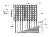
- FIG. 2Ashows an electronically steered artificial impedance surface antenna (AISA), and FIG. 2B shows a side elevation view of an AISA in accordance with the present disclosure;
- AISAelectronically steered artificial impedance surface antenna
- FIG. 3is a diagram of a spherical coordinate system showing the angles and the transformations to Cartesian coordinates in accordance with the prior art
- FIG. 4shows another electronically steered artificial impedance surface antenna (AISA) in accordance with the present disclosure
- FIG. 5shows yet another electronically steered artificial impedance surface antenna (AISA) in accordance with the present disclosure
- FIG. 6shows another side elevation view of an AISA in accordance with the present disclosure.
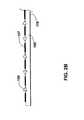
- FIG. 7shows yet another side elevation view of an AISA in accordance with the present disclosure.
- FIG. 2Ashows an electronically steered artificial impedance surface antenna (AISA) in accordance with the present disclosure that is relatively low cost and capable of steering in both theta ( ⁇ ) and phi ( ⁇ ) directions.
- FIG. 3is a diagram of a spherical coordinate system showing the theta ( ⁇ ) and phi ( ⁇ ) angles. In FIG. 3 the phi ( ⁇ ) angle is the angle in the x-y plane, and the theta ( ⁇ ) angle is the angle from the z axis.
- the primary gain lobe of the electronically steered artificial impedance surface antenna (AISA) in accordance with the present disclosureis capable of steering in both theta ( ⁇ ) and phi ( ⁇ ) directions, those skilled in the art refer to it as a 2D electronically steered artificial impedance surface antenna (AISA).
- the electronically steered artificial impedance surface antenna (AISA) of FIG. 2Aincludes a tunable artificial impedance surface antenna (AISA) 101 , a voltage control network 102 , and a one-dimensional 1D radio frequency (RF) feed network 103 .
- AISAtunable artificial impedance surface antenna
- RFradio frequency
- the steering of the primary gain lobe of the electronically steered artificial impedance surface antenna (AISA)is controlled in the phi ( ⁇ ) direction by changing the relative phase difference between the RF surface wave feeds 108 of the 1D RF feed network 103 .
- the theta steeringis controlled by varying or modulating the surface wave impedance of the tunable artificial impedance surface antenna (AISA) 101 .
- the artificial impedance surface antenna (AISA) 101 in the embodiment of FIG. 2Aincludes a dielectric substrate 106 , a periodic array of metallic strips 107 on one surface of the dielectric substrate 106 , varactors 109 electrically connected between the metallic strips 107 , and a 1D array of RF surface wave feeds 108 .
- the impedance of the AISA 101may be varied or modulated by controlling voltages to the metallic strips 107 on the tunable artificial impedance surface antenna (AISA) 101 .
- the voltages on the metallic strips 107change the capacitance of varactors 109 between the metallic strips 107 , which changes the impedance of the AISA 101 , thereby steering the primary gain lobe in the theta direction.
- the voltage control network 102applies direct current (DC) voltages to the metallic strips 107 on the AISA structure.
- Control bus 105provides control for the voltage control network 102 .
- the control bus 105may be from a microprocessor, central processing unit, or any computer or processor.
- Control bus 104provides control for the 1D RF feed network 103 .
- the control bus 104may be from a microprocessor, central processing unit, or any computer or processor.
- FIG. 2Bshows a side elevation view of FIG. 2A .
- varactors 109are between the metallic strips 107 , which are on the surface of the dielectric substrate 106 .
- the dielectric substrate 106may or may not have a ground plane 119 on a surface opposite to the surface upon which the metallic strips 107 are located.
- varactorsare not between the metallic strips 107 .
- the dielectric substrate 106may further include a material 404 with tunable electrical properties, such as a liquid crystal.
- the impedance elementssuch as the metallic strips 107 , which may be formed, deposited, printed, or pasted onto the dielectric substrate 106
- the properties of the dielectric substrate 106 , or the material 404 with tunable electrical propertiesmay change.
- the dielectric constantmay change, thereby changing the impedance between the metallic strips 107 , and thereby steering a beam in the theta direction.
- a varactoris a type of diode whose capacitance varies as a function of the voltage applied across its terminals, which makes it useful for tuning applications.
- varactors 109are used between the metallic strips 107 , as shown in FIG. 2A , by controlling the voltage applied to the varactors 109 via the metallic strips 107 , the capacitances of the varactors 109 vary, which in turn varies or modulates the capacitive coupling and the impedance between the metallic strips 107 to steer a beam in the theta direction.
- the polarities of the varactors 109are aligned such that all the varactor connections to any one of the metallic strips 107 are connected with the same polarity.
- One terminal on a varactormay be referred to as an anode, and the other terminal as a cathode.
- some of the metallic strips 107are only connected to anodes of varactors 109
- other metallic strips 107are only connected to cathodes of varactors 109 .
- adjacent metallic strips 107 on the AISA 101alternate in being connected to anodes or cathodes of varactors 109 .
- the spacing of the metallic strips 107 in one dimension of the AISAmay be a fraction of the RF surface wave (SW) wavelength of the RF waves that propagate across the AISA from the RF surface wave feeds 108 .
- the spacing of the metallic strips 107may be at most 1 ⁇ 5 of the RF surface wave (SW) wavelength of the RF waves.
- the fractionmay be only about 1/10 of the RF surface wave (SW) wavelength of the RF waves.
- the spacing between varactors 109 connected to the metallic strips 107 in a second dimension of the AISAis typically about the same as the spacing between metallic strips.
- the RF SW feeds 108may be a phased array corporate feed structure, or may be conformal surface wave feeds, which are integrated into the AISA, such as by using micro-strips.
- Conformal surface wave feedsthat may be used include those described in U.S. patent application Ser. No. 13/242,102 filed Sep. 23, 2011, or those described in “Directional Coupler for Transverse-Electric Surface Waves”, published in IP.com Prior Art Database Disclosure No. IPCOM000183639D, May 29, 2009, which are incorporated herein by reference as though set forth in full.
- the spacing between the RF SW feeds 108 in the second dimension of the AISA or the y dimension of FIG. 3may be based on rules of thumb for phased array antennas that dictate they be no farther apart than 1 ⁇ 2 of the free-space wavelength for the highest frequency signal to be transmitted or received.
- the thickness of the dielectric substrate 106is determined by its permittivity and the frequency of radiation to be transmitted or received. The higher the permittivity, the thinner the substrate can be.
- the capacitance values of the varactors 109are determined by the range necessary for the desired AISA impedance modulations to obtain the various angles of radiation.
- An AISA operating at about 10 GHzmay use for the dielectric substrate 106 , a 50-mil thick Rogers Corp 3010 circuit board material with a relative permittivity equal to 11.2.
- the metallic strips 107may be spaced 2 millimeters (mm) to 3 mm apart on the dielectric substrate 106 .
- the RF surface wave feeds 108may be spaced 1.5 centimeters (cm) apart and the varactors 109 may be spaced 2 mm to 3 mm apart.
- the varactors 109vary in capacitance from 0.2 to 2.0 pico farads (pF). Designs for different radiation frequencies or designs using different substrates will vary accordingly.
- transmit/receive module 110is connected to the feed network 103 .
- the feed network 103can be of any type that is known to those skilled in the state of the art of phased array antennas.
- the feed network 103 shown in FIG. 2Aincludes a series of RF transmission lines 111 connected to the transmit/receive module 110 , power dividers 112 , and phase shifters 113 .
- the phase shifters 113are controlled by voltage control lines 118 from a digital to analog converter (DAC) 114 that receives digital control signals 104 to control the steering in the phi ( ⁇ ) direction.
- DACdigital to analog converter
- the antenna main lobeis steered in the phi direction by using the feed network 103 to impose a phase shift between each of the RF SW feeds 108 . If the RF SW feeds 108 are spaced uniformly, then the phase shift between adjacent RF SW feeds 108 is constant.
- the RF SW feeds 108may also be spaced non-uniformly, and the phase shifts adjusted accordingly.
- the variation of the surface-wave impedance Z swmay be modulated sinusoidally.
- the beamis steered in the theta direction by tuning the varactor voltages such that X, M, and p result in the desired theta ⁇ .
- the dependence of the surface wave (SW) impedance on the varactor capacitanceis calculated using transcendental equations resulting from the transverse resonance method or by using full-wave numerical simulations.
- voltagesare applied to the varactors 109 by grounding alternate metallic strips 107 to ground 120 and applying tunable voltages via voltage control lines 116 to the rest of the strips 107 .
- the voltage applied to each voltage control line 116is a function of the desired theta ( ⁇ ), and may be different for each voltage control line 116 .
- the voltagesmay be applied from a digital-to-analog converter (DAC) 117 that receives digital controls 105 from a controller for steering in the theta direction.
- the controllermay be a microprocessor, central processing unit (CPU) or any computer, processor or controller.
- An advantage of grounding half of the metallic strips 107is that only half as many voltage control lines 116 are required as there are metallic strips 107 .
- a disadvantageis that the spatial resolution of the voltage control and hence the impedance modulation is limited to twice the spacing between metallic strips.
- FIG. 4shows another electronically steered artificial impedance surface antenna (AISA) in accordance with the present disclosure that is essentially the same as the embodiment described with reference to FIG. 2A , except in the embodiment of FIG. 4 , a voltage is applied to each of the metallic strips 207 by voltage control lines 216 . Twice as many control voltages are required compared to the embodiment of FIG. 2A , however, the spatial resolution of the impedance modulation is doubled.
- the voltage applied to each voltage control line 216is a function of the desired theta ( ⁇ ) angle, and may be different for each voltage control line 216 .
- DACdigital-to-analog converter
- CPUcentral processing unit
- processorany computer or processor
- the antenna main lobeis steered in the phi direction by using the feed network 203 to impose a phase shift between each of the RF SW feeds 208 in the same manner as described with reference to FIG. 1 .
- FIG. 5illustrates a preferred embodiment where the theta ⁇ angle control DACs 117 and 217 of FIGS. 2A and 4 are replaced by a single control voltage from a variable voltage source 350 .
- the AISA radiation anglevaries between a minimum and maximum theta angle that is determined by the details of the AISA design.
- the voltageis applied though voltage control lines 352 and 354 to the metallic strips 340 on the surface of the AISA.
- Voltage control line 354may be a ground with the voltage control line 352 being a variable voltage. Across the x dimension, the metallic strips 340 are alternately tied to voltage control line 352 or to voltage control line 354 .
- One or more varactors diodes 309may be in each gap between adjacent metallic strips 340 and electrically connected to the metallic strips in the same manner as shown in FIG. 2A .
- the metallic stripsmay have centers that are equally spaced in the x dimension, with the widths of the metallic strips 340 periodically varying with a period p 346 .
- the number of metallic strips in a period 346can be any number, although 10 to 20 is reasonable for most designs.
- the width variationis designed to produce surface-wave impedance with a periodic modulation in the X-direction with period p 346 , for example, the sinusoidal variation of equation (8) above.
- the surface-wave impedance at each point on the AISAis determined by the width of the metallic strips and the voltage applied to the varactors 309 .
- the relation between the surface-wave impedance and these parametersis well understood and documented in the references [1]-[9].
- the substrate 401which may be used for dielectric substrates 106 , 206 or 306 , is a material whose electrical permittivity is varied with application of an electric field. As described above, no varactors 109 , 209 or 309 are used in this embodiment.
- a voltageis applied to metallic strips 402 on the AISA, an electric field is produced between adjacent strips and also between the strips and the substrate ground plane 403 . The electric field changes the permittivity of the substrate material, which results in a change in the capacitance between adjacent metallic strips 402 .
- the capacitance between adjacent metallic strips 402determines the surface-wave impedance.
- a voltage differentialmay be applied to adjacent metallic 402 strips, which creates an electric field between the metallic strips 402 and produces a permittivity change in a variable material 404 between the metallic strips 402 .
- the variable material 404may be any electrically variable material, such as liquid crystal material or barium strontium titanate (BST). It may be necessary, especially in the case of using liquid crystals, to embed the variable material 404 in pockets within an inert substrate 405 , as shown in FIG. 7 .
- the antenna main lobeis steered in the phi direction by using the feed network 303 to impose a phase shift between each of the RF SW feeds 308 in the same manner as described with reference to FIG. 2A .
Landscapes
- Physics & Mathematics (AREA)
- Optics & Photonics (AREA)
- Variable-Direction Aerials And Aerial Arrays (AREA)
Abstract
Description
ksw=kosin θo−kp (1)
Z(x)=X+Mcos(2πx/p) (2)
θ=sin−1(n0−λ0/p) (3)
Z({right arrow over (r)})=X+Mcos(konor−{right arrow over (k)}o□{right arrow over (r)}) (5)
Z(x,y)=X+Mcos(ko(nor−xsin θo)) (6)
- 1. Patel, A. M.; Grbic, A., “A Printed Leaky-Wave Antenna Based on a Sinusoidally-Modulated Reactance Surface,” Antennas and Propagation, IEEE Transactions on, vol. 59, no. 6, pp. 2087, 2096, June 2011
- 2. D. Sievenpiper et al, “Holographic AISs for conformal antennas”, 29th Antennas Applications Symposium, 2005
- 3. D. Sievenpiper, J. Colburn, B. Fong, J. Ottusch and J. Visher., 2005 IEEE Antennas and Prop. Symp. Digest, vol. 1B, pp. 256-259, 2005.
- 4. B. Fong et al, “Scalar and Tensor Holographic Artificial Impedance Surfaces,” IEEE TAP., 58, 2010
- 5. D. J. Gregoire and J. S. Colburn,Artificial impedance surface antennas, Proc. Antennas Appl. Symposium 2011, pp. 460-475
- 6. D. J. Gregoire and J. S. Colburn,Artificial impedance surface antenna design and simulation, Proc. Antennas Appl. Symposium 2010, pp. 288-303
- 7. O. Luukkonen et al, “Simple and accurate analytical model of planar grids and high-impedance surfaces comprising metal strips or patches”, IEEE Trans. Antennas Prop., vol. 56, 1624, 2008
- 8. Colburn, J. S.; Lai, A.; Sievenpiper, D. F.; Bekaryan, A.; Fong, B. H.; Ottusch, J. J.; Tulythan, P.; “Adaptive artificial impedance surface conformal antennas,” Antennas and Propagation Society International Symposium, 2009. APSURSI '09. IEEE, vol., no., pp. 1-4, 1-5 Jun. 2009
- 9. Sievenpiper, D.; Schaffner, J.; Lee, J. J.; Livingston, S.; “A steerable leaky-wave antenna using a tunable impedance ground plane,” Antennas and Wireless Propagation Letters, IEEE, vol. 1, no. 1, pp. 179-182, 2002.
φ=sin−1(λΔψ/2πd) (7)
where λ is the radiation wavelength, d is the spacing between SW feeds108, and Δψ is the phase shift between SW feeds108. The RF SW feeds108 may also be spaced non-uniformly, and the phase shifts adjusted accordingly.
Zsw=X+Mcos(2πx/p) (8)
where X and M are the mean impedance and the amplitude of its modulation respectively, and p is the modulation period. The variation of the surface-wave impedance Zswmay be modulated sinusoidally. The theta steering angle θ, is related to the impedance modulation by the equation,
θ=sin−1(nsw−λ/p) (9)
where λ is the wavelength of the radiation, and
nsw=√{square root over ((X/377)2+1)} (10)
is the mean surface-wave index.
θmin=sin−1(nmin−λ/p) (11)
to a maximum of
θmax=sin−1(nmax−λ/p) (12)
with variation of a single control voltage.
Claims (26)
Zsw=X+Mcos(2πx/p)
θ=sin−1(nsw−λ/p)
nsw=√{square root over ((X/377)2+1)}
Priority Applications (9)
| Application Number | Priority Date | Filing Date | Title |
|---|---|---|---|
| US13/934,553US9466887B2 (en) | 2010-11-03 | 2013-07-03 | Low cost, 2D, electronically-steerable, artificial-impedance-surface antenna |
| PCT/US2013/050412WO2015002658A1 (en) | 2013-07-03 | 2013-07-13 | Electronically steerable, artificial impedance, surface antenna |
| EP13888596.7AEP3017504B1 (en) | 2013-07-03 | 2013-07-13 | Electronically steerable, artificial impedance, surface antenna |
| CN201380077921.1ACN105379011B (en) | 2013-07-03 | 2013-07-13 | The artificial impedance skin antenna of electronic controllable |
| US13/961,967US9455495B2 (en) | 2010-11-03 | 2013-08-08 | Two-dimensionally electronically-steerable artificial impedance surface antenna |
| AU2014202093AAU2014202093B2 (en) | 2013-07-03 | 2014-04-15 | Two-dimensionally electronically-steerable artificial impedance surface antenna |
| EP14172603.4AEP2822096B1 (en) | 2013-07-03 | 2014-06-16 | Electronically-steerable artificial impedance surface antenna |
| US14/452,158US9698479B2 (en) | 2010-11-03 | 2014-08-05 | Two-dimensionally electronically-steerable artificial impedance surface antenna |
| US14/682,643US9871293B2 (en) | 2010-11-03 | 2015-04-09 | Two-dimensionally electronically-steerable artificial impedance surface antenna |
Applications Claiming Priority (3)
| Application Number | Priority Date | Filing Date | Title |
|---|---|---|---|
| US12/939,040US8436785B1 (en) | 2010-11-03 | 2010-11-03 | Electrically tunable surface impedance structure with suppressed backward wave |
| US13/242,102US8994609B2 (en) | 2011-09-23 | 2011-09-23 | Conformal surface wave feed |
| US13/934,553US9466887B2 (en) | 2010-11-03 | 2013-07-03 | Low cost, 2D, electronically-steerable, artificial-impedance-surface antenna |
Related Child Applications (1)
| Application Number | Title | Priority Date | Filing Date |
|---|---|---|---|
| US13/961,967Continuation-In-PartUS9455495B2 (en) | 2010-11-03 | 2013-08-08 | Two-dimensionally electronically-steerable artificial impedance surface antenna |
Publications (2)
| Publication Number | Publication Date |
|---|---|
| US20150009070A1 US20150009070A1 (en) | 2015-01-08 |
| US9466887B2true US9466887B2 (en) | 2016-10-11 |
Family
ID=52132424
Family Applications (1)
| Application Number | Title | Priority Date | Filing Date |
|---|---|---|---|
| US13/934,553Expired - Fee RelatedUS9466887B2 (en) | 2010-11-03 | 2013-07-03 | Low cost, 2D, electronically-steerable, artificial-impedance-surface antenna |
Country Status (1)
| Country | Link |
|---|---|
| US (1) | US9466887B2 (en) |
Cited By (4)
| Publication number | Priority date | Publication date | Assignee | Title |
|---|---|---|---|---|
| US20180159210A1 (en)* | 2016-04-27 | 2018-06-07 | Topcon Positioning Systems, Inc. | Antenna radomes forming a cut-off pattern |
| US11038269B2 (en) | 2018-09-10 | 2021-06-15 | Hrl Laboratories, Llc | Electronically steerable holographic antenna with reconfigurable radiators for wideband frequency tuning |
| US11399427B2 (en)* | 2019-10-03 | 2022-07-26 | Lockheed Martin Corporation | HMN unit cell class |
| US11710898B1 (en) | 2020-05-29 | 2023-07-25 | Hrl Laboratories, Llc | Electronically-scanned antennas with distributed amplification |
Families Citing this family (8)
| Publication number | Priority date | Publication date | Assignee | Title |
|---|---|---|---|---|
| US10312596B2 (en)* | 2013-01-17 | 2019-06-04 | Hrl Laboratories, Llc | Dual-polarization, circularly-polarized, surface-wave-waveguide, artificial-impedance-surface antenna |
| EP3079204B1 (en)* | 2015-04-09 | 2021-04-07 | The Boeing Company | Two-dimensionally electronically-steerable artificial impedance surface antenna |
| US10490905B2 (en)* | 2016-07-11 | 2019-11-26 | Waymo Llc | Radar antenna array with parasitic elements excited by surface waves |
| EP3300172A1 (en)* | 2016-09-22 | 2018-03-28 | British Telecommunications public limited company | Beamsteering using metamaterials |
| LU100258B1 (en)* | 2017-05-19 | 2019-01-04 | Iee Sa | Tunable Metamaterial Lens for Radar Sensing |
| US10811782B2 (en)* | 2018-04-27 | 2020-10-20 | Hrl Laboratories, Llc | Holographic antenna arrays with phase-matched feeds and holographic phase correction for holographic antenna arrays without phase-matched feeds |
| US11075459B2 (en) | 2019-01-28 | 2021-07-27 | Mediatek Inc. | Millimeter wave antenna device including parasitic elements capable of improving antenna pattern |
| CN117795777B (en)* | 2022-07-27 | 2025-09-16 | 京东方科技集团股份有限公司 | Waveguide, beam adjusting device, beam adjusting method and manufacturing method |
Citations (206)
| Publication number | Priority date | Publication date | Assignee | Title |
|---|---|---|---|---|
| US3267480A (en) | 1961-02-23 | 1966-08-16 | Hazeltine Research Inc | Polarization converter |
| GB1145208A (en) | 1966-09-27 | 1969-03-12 | Marconi Instruments Ltd | Improvements in or relating to remotely controllable electromagnetic switches for use at radio frequency |
| US3560978A (en) | 1968-11-01 | 1971-02-02 | Itt | Electronically controlled antenna system |
| US3810183A (en) | 1970-12-18 | 1974-05-07 | Ball Brothers Res Corp | Dual slot antenna device |
| US3961333A (en) | 1974-08-29 | 1976-06-01 | Texas Instruments Incorporated | Radome wire grid having low pass frequency characteristics |
| US4045800A (en) | 1975-05-22 | 1977-08-30 | Hughes Aircraft Company | Phase steered subarray antenna |
| US4051477A (en) | 1976-02-17 | 1977-09-27 | Ball Brothers Research Corporation | Wide beam microstrip radiator |
| US4087822A (en) | 1976-08-26 | 1978-05-02 | Raytheon Company | Radio frequency antenna having microstrip feed network and flared radiating aperture |
| US4119972A (en) | 1977-02-03 | 1978-10-10 | Nasa | Phased array antenna control |
| US4123759A (en) | 1977-03-21 | 1978-10-31 | Microwave Associates, Inc. | Phased array antenna |
| US4124852A (en) | 1977-01-24 | 1978-11-07 | Raytheon Company | Phased power switching system for scanning antenna array |
| US4127586A (en) | 1970-06-19 | 1978-11-28 | Ciba-Geigy Corporation | Light protection agents |
| US4150382A (en) | 1973-09-13 | 1979-04-17 | Wisconsin Alumni Research Foundation | Non-uniform variable guided wave antennas with electronically controllable scanning |
| US4173759A (en) | 1978-11-06 | 1979-11-06 | Cubic Corporation | Adaptive antenna array and method of operating same |
| US4189733A (en) | 1978-12-08 | 1980-02-19 | Northrop Corporation | Adaptive electronically steerable phased array |
| US4217587A (en) | 1978-08-14 | 1980-08-12 | Westinghouse Electric Corp. | Antenna beam steering controller |
| US4220954A (en) | 1977-12-20 | 1980-09-02 | Marchand Electronic Laboratories, Incorporated | Adaptive antenna system employing FM receiver |
| US4236158A (en) | 1979-03-22 | 1980-11-25 | Motorola, Inc. | Steepest descent controller for an adaptive antenna array |
| US4242685A (en) | 1979-04-27 | 1980-12-30 | Ball Corporation | Slotted cavity antenna |
| US4266203A (en) | 1977-02-25 | 1981-05-05 | Thomson-Csf | Microwave polarization transformer |
| US4308541A (en) | 1979-12-21 | 1981-12-29 | Nasa | Antenna feed system for receiving circular polarization and transmitting linear polarization |
| US4367475A (en) | 1979-10-30 | 1983-01-04 | Ball Corporation | Linearly polarized r.f. radiating slot |
| US4370659A (en) | 1981-07-20 | 1983-01-25 | Sperry Corporation | Antenna |
| US4387377A (en) | 1980-06-24 | 1983-06-07 | Siemens Aktiengesellschaft | Apparatus for converting the polarization of electromagnetic waves |
| US4395713A (en) | 1980-05-06 | 1983-07-26 | Antenna, Incorporated | Transit antenna |
| US4443802A (en) | 1981-04-22 | 1984-04-17 | University Of Illinois Foundation | Stripline fed hybrid slot antenna |
| US4590478A (en) | 1983-06-15 | 1986-05-20 | Sanders Associates, Inc. | Multiple ridge antenna |
| US4594595A (en) | 1984-04-18 | 1986-06-10 | Sanders Associates, Inc. | Circular log-periodic direction-finder array |
| JPS61260702A (en) | 1985-05-15 | 1986-11-18 | Hitachi Ltd | microwave changeover switch |
| US4672386A (en) | 1984-01-05 | 1987-06-09 | Plessey Overseas Limited | Antenna with radial and edge slot radiators fed with stripline |
| US4684953A (en) | 1984-01-09 | 1987-08-04 | Mcdonnell Douglas Corporation | Reduced height monopole/crossed slot antenna |
| US4700197A (en) | 1984-07-02 | 1987-10-13 | Canadian Patents & Development Ltd. | Adaptive array antenna |
| US4737795A (en) | 1986-07-25 | 1988-04-12 | General Motors Corporation | Vehicle roof mounted slot antenna with AM and FM grounding |
| US4749996A (en) | 1983-08-29 | 1988-06-07 | Allied-Signal Inc. | Double tuned, coupled microstrip antenna |
| US4760402A (en) | 1985-05-30 | 1988-07-26 | Nippondenso Co., Ltd. | Antenna system incorporated in the air spoiler of an automobile |
| US4782346A (en) | 1986-03-11 | 1988-11-01 | General Electric Company | Finline antennas |
| US4803494A (en) | 1987-03-14 | 1989-02-07 | Stc Plc | Wide band antenna |
| US4821040A (en) | 1986-12-23 | 1989-04-11 | Ball Corporation | Circular microstrip vehicular rf antenna |
| US4835541A (en) | 1986-12-29 | 1989-05-30 | Ball Corporation | Near-isotropic low-profile microstrip radiator especially suited for use as a mobile vehicle antenna |
| US4843403A (en) | 1987-07-29 | 1989-06-27 | Ball Corporation | Broadband notch antenna |
| US4843400A (en) | 1988-08-09 | 1989-06-27 | Ford Aerospace Corporation | Aperture coupled circular polarization antenna |
| US4853704A (en) | 1988-05-23 | 1989-08-01 | Ball Corporation | Notch antenna with microstrip feed |
| US4903033A (en) | 1988-04-01 | 1990-02-20 | Ford Aerospace Corporation | Planar dual polarization antenna |
| US4905014A (en) | 1988-04-05 | 1990-02-27 | Malibu Research Associates, Inc. | Microwave phasing structures for electromagnetically emulating reflective surfaces and focusing elements of selected geometry |
| US4916457A (en) | 1988-06-13 | 1990-04-10 | Teledyne Industries, Inc. | Printed-circuit crossed-slot antenna |
| US4922263A (en) | 1986-04-23 | 1990-05-01 | L'etat Francais, Represente Par Le Ministre Des Ptt, Centre National D'etudes Des Telecommunications (Cnet) | Plate antenna with double crossed polarizations |
| US4958165A (en) | 1987-06-09 | 1990-09-18 | Thorm EMI plc | Circular polarization antenna |
| US4975712A (en) | 1989-01-23 | 1990-12-04 | Trw Inc. | Two-dimensional scanning antenna |
| US5021795A (en) | 1989-06-23 | 1991-06-04 | Motorola, Inc. | Passive temperature compensation scheme for microstrip antennas |
| US5023623A (en) | 1989-12-21 | 1991-06-11 | Hughes Aircraft Company | Dual mode antenna apparatus having slotted waveguide and broadband arrays |
| US5070340A (en) | 1989-07-06 | 1991-12-03 | Ball Corporation | Broadband microstrip-fed antenna |
| US5081466A (en) | 1990-05-04 | 1992-01-14 | Motorola, Inc. | Tapered notch antenna |
| US5115217A (en) | 1990-12-06 | 1992-05-19 | California Institute Of Technology | RF tuning element |
| US5146235A (en) | 1989-12-18 | 1992-09-08 | Akg Akustische U. Kino-Gerate Gesellschaft M.B.H. | Helical uhf transmitting and/or receiving antenna |
| US5158611A (en) | 1985-10-28 | 1992-10-27 | Sumitomo Chemical Co., Ltd. | Paper coating composition |
| US5208603A (en) | 1990-06-15 | 1993-05-04 | The Boeing Company | Frequency selective surface (FSS) |
| US5218374A (en) | 1988-09-01 | 1993-06-08 | Apti, Inc. | Power beaming system with printer circuit radiating elements having resonating cavities |
| US5235343A (en) | 1990-08-21 | 1993-08-10 | Societe D'etudes Et De Realisation De Protection Electronique Informatique Electronique | High frequency antenna with a variable directing radiation pattern |
| US5268696A (en) | 1992-04-06 | 1993-12-07 | Westinghouse Electric Corp. | Slotline reflective phase shifting array element utilizing electrostatic switches |
| US5268701A (en) | 1992-03-23 | 1993-12-07 | Raytheon Company | Radio frequency antenna |
| WO1994000891A1 (en) | 1992-06-29 | 1994-01-06 | Loughborough University Of Technology | Reconfigurable frequency selective surfaces |
| US5278562A (en) | 1992-08-07 | 1994-01-11 | Hughes Missile Systems Company | Method and apparatus using photoresistive materials as switchable EMI barriers and shielding |
| US5287116A (en) | 1991-05-30 | 1994-02-15 | Kabushiki Kaisha Toshiba | Array antenna generating circularly polarized waves with a plurality of microstrip antennas |
| US5287118A (en) | 1990-07-24 | 1994-02-15 | British Aerospace Public Limited Company | Layer frequency selective surface assembly and method of modulating the power or frequency characteristics thereof |
| US5402134A (en) | 1993-03-01 | 1995-03-28 | R. A. Miller Industries, Inc. | Flat plate antenna module |
| US5406292A (en) | 1993-06-09 | 1995-04-11 | Ball Corporation | Crossed-slot antenna having infinite balun feed means |
| US5519408A (en) | 1991-01-22 | 1996-05-21 | Us Air Force | Tapered notch antenna using coplanar waveguide |
| US5525954A (en) | 1993-08-09 | 1996-06-11 | Oki Electric Industry Co., Ltd. | Stripline resonator |
| US5532709A (en) | 1994-11-02 | 1996-07-02 | Ford Motor Company | Directional antenna for vehicle entry system |
| US5531018A (en) | 1993-12-20 | 1996-07-02 | General Electric Company | Method of micromachining electromagnetically actuated current switches with polyimide reinforcement seals, and switches produced thereby |
| US5534877A (en) | 1989-12-14 | 1996-07-09 | Comsat | Orthogonally polarized dual-band printed circuit antenna employing radiating elements capacitively coupled to feedlines |
| US5541614A (en) | 1995-04-04 | 1996-07-30 | Hughes Aircraft Company | Smart antenna system using microelectromechanically tunable dipole antennas and photonic bandgap materials |
| US5557291A (en) | 1995-05-25 | 1996-09-17 | Hughes Aircraft Company | Multiband, phased-array antenna with interleaved tapered-element and waveguide radiators |
| WO1996029621A1 (en) | 1995-03-17 | 1996-09-26 | Massachusetts Institute Of Technology | Metallodielectric photonic crystal |
| US5581266A (en) | 1993-01-04 | 1996-12-03 | Peng; Sheng Y. | Printed-circuit crossed-slot antenna |
| US5589845A (en) | 1992-12-01 | 1996-12-31 | Superconducting Core Technologies, Inc. | Tuneable electric antenna apparatus including ferroelectric material |
| US5598172A (en) | 1990-11-06 | 1997-01-28 | Thomson - Csf Radant | Dual-polarization microwave lens and its application to a phased-array antenna |
| US5600325A (en) | 1995-06-07 | 1997-02-04 | Hughes Electronics | Ferro-electric frequency selective surface radome |
| US5611940A (en) | 1994-04-28 | 1997-03-18 | Siemens Aktiengesellschaft | Microsystem with integrated circuit and micromechanical component, and production process |
| US5619365A (en) | 1992-06-08 | 1997-04-08 | Texas Instruments Incorporated | Elecronically tunable optical periodic surface filters with an alterable resonant frequency |
| US5621571A (en) | 1994-02-14 | 1997-04-15 | Minnesota Mining And Manufacturing Company | Integrated retroreflective electronic display |
| EP0539297B1 (en) | 1991-10-25 | 1997-05-28 | Commissariat A L'energie Atomique | Device with adjustable frequency selective surface |
| GB2281662B (en) | 1993-09-07 | 1997-06-04 | Alcatel Espace | A wideband and low band listening instrument for space aplications |
| US5638946A (en) | 1996-01-11 | 1997-06-17 | Northeastern University | Micromechanical switch with insulated switch contact |
| US5644319A (en) | 1995-05-31 | 1997-07-01 | Industrial Technology Research Institute | Multi-resonance horizontal-U shaped antenna |
| US5694134A (en) | 1992-12-01 | 1997-12-02 | Superconducting Core Technologies, Inc. | Phased array antenna system including a coplanar waveguide feed arrangement |
| US5709245A (en) | 1994-09-23 | 1998-01-20 | The Boeing Company | Optically controlled actuator |
| WO1998021734A1 (en) | 1996-11-12 | 1998-05-22 | Fraunhofer-Gesellschaft zur Förderung der angewandten Forschung e.V. | Method for manufacturing a micromechanical relay |
| US5767807A (en) | 1996-06-05 | 1998-06-16 | International Business Machines Corporation | Communication system and methods utilizing a reactively controlled directive array |
| US5808527A (en) | 1996-12-21 | 1998-09-15 | Hughes Electronics Corporation | Tunable microwave network using microelectromechanical switches |
| US5874915A (en) | 1997-08-08 | 1999-02-23 | Raytheon Company | Wideband cylindrical UHF array |
| US5892485A (en) | 1997-02-25 | 1999-04-06 | Pacific Antenna Technologies | Dual frequency reflector antenna feed element |
| US5894288A (en) | 1997-08-08 | 1999-04-13 | Raytheon Company | Wideband end-fire array |
| US5905465A (en) | 1997-04-23 | 1999-05-18 | Ball Aerospace & Technologies Corp. | Antenna system |
| US5923303A (en) | 1997-12-24 | 1999-07-13 | U S West, Inc. | Combined space and polarization diversity antennas |
| US5926139A (en) | 1997-07-02 | 1999-07-20 | Lucent Technologies Inc. | Planar dual frequency band antenna |
| US5929819A (en) | 1996-12-17 | 1999-07-27 | Hughes Electronics Corporation | Flat antenna for satellite communication |
| US5943016A (en) | 1995-12-07 | 1999-08-24 | Atlantic Aerospace Electronics, Corp. | Tunable microstrip patch antenna and feed network therefor |
| US5945951A (en) | 1997-09-03 | 1999-08-31 | Andrew Corporation | High isolation dual polarized antenna system with microstrip-fed aperture coupled patches |
| US5949382A (en) | 1990-09-28 | 1999-09-07 | Raytheon Company | Dielectric flare notch radiator with separate transmit and receive ports |
| WO1999050929A1 (en) | 1998-03-30 | 1999-10-07 | The Regents Of The University Of California | Circuit and method for eliminating surface currents on metals |
| US5966096A (en) | 1996-04-24 | 1999-10-12 | France Telecom | Compact printed antenna for radiation at low elevation |
| US5966101A (en) | 1997-05-09 | 1999-10-12 | Motorola, Inc. | Multi-layered compact slot antenna structure and method |
| US6005521A (en) | 1996-04-25 | 1999-12-21 | Kyocera Corporation | Composite antenna |
| US6005519A (en) | 1996-09-04 | 1999-12-21 | 3 Com Corporation | Tunable microstrip antenna and method for tuning the same |
| US6008770A (en) | 1996-06-24 | 1999-12-28 | Ricoh Company, Ltd. | Planar antenna and antenna array |
| US6016125A (en) | 1996-08-29 | 2000-01-18 | Telefonaktiebolaget Lm Ericsson | Antenna device and method for portable radio equipment |
| US6028561A (en) | 1997-03-10 | 2000-02-22 | Hitachi, Ltd | Tunable slot antenna |
| US6034655A (en) | 1996-07-02 | 2000-03-07 | Lg Electronics Inc. | Method for controlling white balance in plasma display panel device |
| US6034644A (en) | 1997-05-30 | 2000-03-07 | Hitachi, Ltd. | Tunable slot antenna with capacitively coupled slot island conductor for precise impedance adjustment |
| US6037905A (en) | 1998-08-06 | 2000-03-14 | The United States Of America As Represented By The Secretary Of The Army | Azimuth steerable antenna |
| US6040803A (en) | 1998-02-19 | 2000-03-21 | Ericsson Inc. | Dual band diversity antenna having parasitic radiating element |
| US6046659A (en) | 1998-05-15 | 2000-04-04 | Hughes Electronics Corporation | Design and fabrication of broadband surface-micromachined micro-electro-mechanical switches for microwave and millimeter-wave applications |
| US6046655A (en) | 1997-11-10 | 2000-04-04 | Datron/Transco Inc. | Antenna feed system |
| US6055079A (en) | 1997-08-07 | 2000-04-25 | The Regents Of The University Of California | Optical key system |
| US6054659A (en) | 1998-03-09 | 2000-04-25 | General Motors Corporation | Integrated electrostatically-actuated micromachined all-metal micro-relays |
| FR2785476A1 (en) | 1998-11-04 | 2000-05-05 | Thomson Multimedia Sa | Multiple beam wireless reception system has circular multiple beam printed circuit with beam switching mechanism, mounted on camera |
| US6061025A (en) | 1995-12-07 | 2000-05-09 | Atlantic Aerospace Electronics Corporation | Tunable microstrip patch antenna and control system therefor |
| US6075485A (en) | 1998-11-03 | 2000-06-13 | Atlantic Aerospace Electronics Corp. | Reduced weight artificial dielectric antennas and method for providing the same |
| US6081239A (en) | 1998-10-23 | 2000-06-27 | Gradient Technologies, Llc | Planar antenna including a superstrate lens having an effective dielectric constant |
| US6081235A (en) | 1998-04-30 | 2000-06-27 | The United States Of America As Represented By The Administrator Of The National Aeronautics And Space Administration | High resolution scanning reflectarray antenna |
| WO2000044012A1 (en) | 1999-01-25 | 2000-07-27 | GFD-Gesellschaft für Diamantprodukte mbH | Microswitching contact |
| US6097343A (en) | 1998-10-23 | 2000-08-01 | Trw Inc. | Conformal load-bearing antenna system that excites aircraft structure |
| US6097263A (en) | 1996-06-28 | 2000-08-01 | Robert M. Yandrofski | Method and apparatus for electrically tuning a resonating device |
| US6118410A (en) | 1999-07-29 | 2000-09-12 | General Motors Corporation | Automobile roof antenna shelf |
| US6118406A (en) | 1998-12-21 | 2000-09-12 | The United States Of America As Represented By The Secretary Of The Navy | Broadband direct fed phased array antenna comprising stacked patches |
| US6127908A (en) | 1997-11-17 | 2000-10-03 | Massachusetts Institute Of Technology | Microelectro-mechanical system actuator device and reconfigurable circuits utilizing same |
| US6150989A (en) | 1999-07-06 | 2000-11-21 | Sky Eye Railway Services International Inc. | Cavity-backed slot antenna resonating at two different frequencies |
| US6154176A (en) | 1998-08-07 | 2000-11-28 | Sarnoff Corporation | Antennas formed using multilayer ceramic substrates |
| US6166705A (en) | 1999-07-20 | 2000-12-26 | Harris Corporation | Multi title-configured phased array antenna architecture |
| US6175723B1 (en) | 1998-08-12 | 2001-01-16 | Board Of Trustees Operating Michigan State University | Self-structuring antenna system with a switchable antenna array and an optimizing controller |
| US6175337B1 (en) | 1999-09-17 | 2001-01-16 | The United States Of America As Represented By The Secretary Of The Army | High-gain, dielectric loaded, slotted waveguide antenna |
| US6191724B1 (en) | 1999-01-28 | 2001-02-20 | Mcewan Thomas E. | Short pulse microwave transceiver |
| US6198438B1 (en) | 1999-10-04 | 2001-03-06 | The United States Of America As Represented By The Secretary Of The Air Force | Reconfigurable microstrip antenna array geometry which utilizes micro-electro-mechanical system (MEMS) switches |
| US6198441B1 (en) | 1998-07-21 | 2001-03-06 | Hitachi, Ltd. | Wireless handset |
| US6204819B1 (en) | 2000-05-22 | 2001-03-20 | Telefonaktiebolaget L.M. Ericsson | Convertible loop/inverted-f antennas and wireless communicators incorporating the same |
| US6218997B1 (en) | 1998-04-20 | 2001-04-17 | Fuba Automotive Gmbh | Antenna for a plurality of radio services |
| US6218912B1 (en) | 1998-05-16 | 2001-04-17 | Robert Bosch Gmbh | Microwave switch with grooves for isolation of the passages |
| WO2001031737A1 (en) | 1999-10-29 | 2001-05-03 | Allgon Ab | An antenna device for transmitting and/or receiving rf waves |
| US6246377B1 (en) | 1998-11-02 | 2001-06-12 | Fantasma Networks, Inc. | Antenna comprising two separate wideband notch regions on one coplanar substrate |
| US6252473B1 (en) | 1999-01-06 | 2001-06-26 | Hughes Electronics Corporation | Polyhedral-shaped redundant coaxial switch |
| US6285325B1 (en) | 2000-02-16 | 2001-09-04 | The United States Of America As Represented By The Secretary Of The Army | Compact wideband microstrip antenna with leaky-wave excitation |
| US6297579B1 (en) | 2000-11-13 | 2001-10-02 | Sandia National Laboratories | Electron gun controlled smart structure |
| WO2001073891A1 (en) | 2000-03-29 | 2001-10-04 | Hrl Laboratories, Llc. | An electronically tunable reflector |
| WO2001073893A1 (en) | 2000-03-29 | 2001-10-04 | Hrl Laboratories, Llc | A tunable impedance surface |
| US6307519B1 (en) | 1999-12-23 | 2001-10-23 | Hughes Electronics Corporation | Multiband antenna system using RF micro-electro-mechanical switches, method for transmitting multiband signals, and signal produced therefrom |
| US20010035801A1 (en) | 2000-03-17 | 2001-11-01 | Gilbert Roland A. | Reconfigurable diplexer for communications applications |
| US6317095B1 (en) | 1998-09-30 | 2001-11-13 | Anritsu Corporation | Planar antenna and method for manufacturing the same |
| US6323826B1 (en) | 2000-03-28 | 2001-11-27 | Hrl Laboratories, Llc | Tunable-impedance spiral |
| US6337668B1 (en) | 1999-03-05 | 2002-01-08 | Matsushita Electric Industrial Co., Ltd. | Antenna apparatus |
| GB2328748B (en) | 1997-08-30 | 2002-02-20 | Ford Motor Co | Improvements in sensor assemblies for automotive collision warning systems |
| US20020036586A1 (en) | 2000-09-22 | 2002-03-28 | Tantivy Communications, Inc. | Adaptive antenna for use in wireless communication systems |
| US6366254B1 (en) | 2000-03-15 | 2002-04-02 | Hrl Laboratories, Llc | Planar antenna with switched beam diversity for interference reduction in a mobile environment |
| US6380895B1 (en) | 1997-07-09 | 2002-04-30 | Allgon Ab | Trap microstrip PIFA |
| US6388631B1 (en) | 2001-03-19 | 2002-05-14 | Hrl Laboratories Llc | Reconfigurable interleaved phased array antenna |
| US6404390B2 (en) | 2000-06-02 | 2002-06-11 | Industrial Technology Research Institute | Wideband microstrip leaky-wave antenna and its feeding system |
| US6404401B2 (en) | 2000-04-28 | 2002-06-11 | Bae Systems Information And Electronic Systems Integration Inc. | Metamorphic parallel plate antenna |
| US6407719B1 (en) | 1999-07-08 | 2002-06-18 | Atr Adaptive Communications Research Laboratories | Array antenna |
| US6417807B1 (en) | 2001-04-27 | 2002-07-09 | Hrl Laboratories, Llc | Optically controlled RF MEMS switch array for reconfigurable broadband reflective antennas |
| US6424319B2 (en) | 1999-11-18 | 2002-07-23 | Automotive Systems Laboratory, Inc. | Multi-beam antenna |
| US6426722B1 (en) | 2000-03-08 | 2002-07-30 | Hrl Laboratories, Llc | Polarization converting radio frequency reflecting surface |
| US6440767B1 (en) | 2001-01-23 | 2002-08-27 | Hrl Laboratories, Llc | Monolithic single pole double throw RF MEMS switch |
| US6469673B2 (en) | 2000-06-30 | 2002-10-22 | Nokia Mobile Phones Ltd. | Antenna circuit arrangement and testing method |
| US6473362B1 (en) | 2001-04-30 | 2002-10-29 | Information System Laboratories, Inc. | Narrowband beamformer using nonlinear oscillators |
| US6496155B1 (en) | 2000-03-29 | 2002-12-17 | Hrl Laboratories, Llc. | End-fire antenna or array on surface with tunable impedance |
| WO2003009501A1 (en) | 2001-07-19 | 2003-01-30 | Deskin Research Group, Inc. | Exciter system and method for communications within an enclosed space |
| US6515635B2 (en) | 2000-09-22 | 2003-02-04 | Tantivy Communications, Inc. | Adaptive antenna for use in wireless communication systems |
| US6518931B1 (en) | 2000-03-15 | 2003-02-11 | Hrl Laboratories, Llc | Vivaldi cloverleaf antenna |
| US20030034922A1 (en) | 2001-08-17 | 2003-02-20 | Isaacs Eric D. | Resonant antennas |
| US6525695B2 (en) | 2001-04-30 | 2003-02-25 | E-Tenna Corporation | Reconfigurable artificial magnetic conductor using voltage controlled capacitors with coplanar resistive biasing network |
| US6538621B1 (en) | 2000-03-29 | 2003-03-25 | Hrl Laboratories, Llc | Tunable impedance surface |
| US6624720B1 (en) | 2002-08-15 | 2003-09-23 | Raytheon Company | Micro electro-mechanical system (MEMS) transfer switch for wideband device |
| US20030193446A1 (en) | 2002-04-15 | 2003-10-16 | Paratek Microwave, Inc. | Electronically steerable passive array antenna |
| US6642889B1 (en) | 2002-05-03 | 2003-11-04 | Raytheon Company | Asymmetric-element reflect array antenna |
| WO2003098732A1 (en) | 2002-05-15 | 2003-11-27 | Hrl Laboratories, Llc | A switch arrangement and method of making same |
| US6657525B1 (en) | 2002-05-31 | 2003-12-02 | Northrop Grumman Corporation | Microelectromechanical RF switch |
| US20030222738A1 (en) | 2001-12-03 | 2003-12-04 | Memgen Corporation | Miniature RF and microwave components and methods for fabricating such components |
| DE19600609B4 (en) | 1995-09-30 | 2004-02-19 | Eads Deutschland Gmbh | Polarizer for converting a linearly polarized wave into a circularly polarized wave or into a linearly polarized wave with rotated polarization and vice versa |
| EP1158605B1 (en) | 2000-05-26 | 2004-04-14 | Sony International (Europe) GmbH | V-Slot antenna for circular polarization |
| US6741207B1 (en) | 2000-06-30 | 2004-05-25 | Raytheon Company | Multi-bit phase shifters using MEM RF switches |
| US20040113713A1 (en) | 2002-12-17 | 2004-06-17 | Eliav Zipper | Switch arcitecture using mems switches and solid state switches in parallel |
| US20040135649A1 (en) | 2002-05-15 | 2004-07-15 | Sievenpiper Daniel F | Single-pole multi-throw switch having low parasitic reactance, and an antenna incorporating the same |
| US20040227583A1 (en) | 2003-05-12 | 2004-11-18 | Hrl Laboratories, Llc | RF MEMS switch with integrated impedance matching structure |
| US20040227668A1 (en) | 2003-05-12 | 2004-11-18 | Hrl Laboratories, Llc | Steerable leaky wave antenna capable of both forward and backward radiation |
| US20040227664A1 (en) | 2003-05-15 | 2004-11-18 | Noujeim Karam Michael | Leaky wave microstrip antenna with a prescribable pattern |
| US20040227678A1 (en) | 2003-05-12 | 2004-11-18 | Hrl Laboratories, Llc | Compact tunable antenna |
| US20040227667A1 (en) | 2003-05-12 | 2004-11-18 | Hrl Laboratories, Llc | Meta-element antenna and array |
| US6822622B2 (en) | 2002-07-29 | 2004-11-23 | Ball Aerospace & Technologies Corp | Electronically reconfigurable microwave lens and shutter using cascaded frequency selective surfaces and polyimide macro-electro-mechanical systems |
| US20040263408A1 (en) | 2003-05-12 | 2004-12-30 | Hrl Laboratories, Llc | Adaptive beam forming antenna system using a tunable impedance surface |
| US20050012667A1 (en) | 2003-06-20 | 2005-01-20 | Anritsu Company | Fixed-frequency beam-steerable leaky-wave microstrip antenna |
| US6864848B2 (en) | 2001-12-27 | 2005-03-08 | Hrl Laboratories, Llc | RF MEMs-tuned slot antenna and a method of making same |
| US6897810B2 (en) | 2002-11-13 | 2005-05-24 | Hon Hai Precision Ind. Co., Ltd | Multi-band antenna |
| US20060192465A1 (en) | 2004-03-12 | 2006-08-31 | Sri International, A California Corporation | Mechanical meta-materials |
| US7173565B2 (en) | 2004-07-30 | 2007-02-06 | Hrl Laboratories, Llc | Tunable frequency selective surface |
| US7218281B2 (en) | 2005-07-01 | 2007-05-15 | Hrl Laboratories, Llc | Artificial impedance structure |
| US7307589B1 (en) | 2005-12-29 | 2007-12-11 | Hrl Laboratories, Llc | Large-scale adaptive surface sensor arrays |
| US7782255B2 (en) | 2007-10-23 | 2010-08-24 | The Boeing Company | System and methods for radar and communications applications |
| US7791251B2 (en) | 2005-03-17 | 2010-09-07 | Inha-Industry Partnership Institute | Biomimetic electro-active paper actuators |
| US7830310B1 (en) | 2005-07-01 | 2010-11-09 | Hrl Laboratories, Llc | Artificial impedance structure |
| US7911386B1 (en) | 2006-05-23 | 2011-03-22 | The Regents Of The University Of California | Multi-band radiating elements with composite right/left-handed meta-material transmission line |
| US8212739B2 (en) | 2007-05-15 | 2012-07-03 | Hrl Laboratories, Llc | Multiband tunable impedance surface |
| US20120194399A1 (en)* | 2010-10-15 | 2012-08-02 | Adam Bily | Surface scattering antennas |
| US20120235848A1 (en)* | 2011-03-14 | 2012-09-20 | Bruno William M | Metamaterial for a radio frequency communications apparatus |
| US20130021112A1 (en)* | 2011-07-21 | 2013-01-24 | Apostolos John T | Method and apparatus for avoiding pattern blockage due to scatter |
| US8436785B1 (en) | 2010-11-03 | 2013-05-07 | Hrl Laboratories, Llc | Electrically tunable surface impedance structure with suppressed backward wave |
| US20140038662A1 (en)* | 2012-03-26 | 2014-02-06 | Motorola Mobility Llc | Method and apparatus for compensating for phase shift in a communication device |
- 2013
- 2013-07-03USUS13/934,553patent/US9466887B2/ennot_activeExpired - Fee Related
Patent Citations (225)
| Publication number | Priority date | Publication date | Assignee | Title |
|---|---|---|---|---|
| US3267480A (en) | 1961-02-23 | 1966-08-16 | Hazeltine Research Inc | Polarization converter |
| GB1145208A (en) | 1966-09-27 | 1969-03-12 | Marconi Instruments Ltd | Improvements in or relating to remotely controllable electromagnetic switches for use at radio frequency |
| US3560978A (en) | 1968-11-01 | 1971-02-02 | Itt | Electronically controlled antenna system |
| US4127586A (en) | 1970-06-19 | 1978-11-28 | Ciba-Geigy Corporation | Light protection agents |
| US3810183A (en) | 1970-12-18 | 1974-05-07 | Ball Brothers Res Corp | Dual slot antenna device |
| US4150382A (en) | 1973-09-13 | 1979-04-17 | Wisconsin Alumni Research Foundation | Non-uniform variable guided wave antennas with electronically controllable scanning |
| US3961333A (en) | 1974-08-29 | 1976-06-01 | Texas Instruments Incorporated | Radome wire grid having low pass frequency characteristics |
| US4045800A (en) | 1975-05-22 | 1977-08-30 | Hughes Aircraft Company | Phase steered subarray antenna |
| US4051477A (en) | 1976-02-17 | 1977-09-27 | Ball Brothers Research Corporation | Wide beam microstrip radiator |
| US4087822A (en) | 1976-08-26 | 1978-05-02 | Raytheon Company | Radio frequency antenna having microstrip feed network and flared radiating aperture |
| US4124852A (en) | 1977-01-24 | 1978-11-07 | Raytheon Company | Phased power switching system for scanning antenna array |
| US4119972A (en) | 1977-02-03 | 1978-10-10 | Nasa | Phased array antenna control |
| US4266203A (en) | 1977-02-25 | 1981-05-05 | Thomson-Csf | Microwave polarization transformer |
| US4123759A (en) | 1977-03-21 | 1978-10-31 | Microwave Associates, Inc. | Phased array antenna |
| US4220954A (en) | 1977-12-20 | 1980-09-02 | Marchand Electronic Laboratories, Incorporated | Adaptive antenna system employing FM receiver |
| US4217587A (en) | 1978-08-14 | 1980-08-12 | Westinghouse Electric Corp. | Antenna beam steering controller |
| US4173759A (en) | 1978-11-06 | 1979-11-06 | Cubic Corporation | Adaptive antenna array and method of operating same |
| US4189733A (en) | 1978-12-08 | 1980-02-19 | Northrop Corporation | Adaptive electronically steerable phased array |
| US4236158A (en) | 1979-03-22 | 1980-11-25 | Motorola, Inc. | Steepest descent controller for an adaptive antenna array |
| US4242685A (en) | 1979-04-27 | 1980-12-30 | Ball Corporation | Slotted cavity antenna |
| US4367475A (en) | 1979-10-30 | 1983-01-04 | Ball Corporation | Linearly polarized r.f. radiating slot |
| US4308541A (en) | 1979-12-21 | 1981-12-29 | Nasa | Antenna feed system for receiving circular polarization and transmitting linear polarization |
| US4395713A (en) | 1980-05-06 | 1983-07-26 | Antenna, Incorporated | Transit antenna |
| US4387377A (en) | 1980-06-24 | 1983-06-07 | Siemens Aktiengesellschaft | Apparatus for converting the polarization of electromagnetic waves |
| US4443802A (en) | 1981-04-22 | 1984-04-17 | University Of Illinois Foundation | Stripline fed hybrid slot antenna |
| US4370659A (en) | 1981-07-20 | 1983-01-25 | Sperry Corporation | Antenna |
| US4590478A (en) | 1983-06-15 | 1986-05-20 | Sanders Associates, Inc. | Multiple ridge antenna |
| US4749996A (en) | 1983-08-29 | 1988-06-07 | Allied-Signal Inc. | Double tuned, coupled microstrip antenna |
| US4672386A (en) | 1984-01-05 | 1987-06-09 | Plessey Overseas Limited | Antenna with radial and edge slot radiators fed with stripline |
| US4684953A (en) | 1984-01-09 | 1987-08-04 | Mcdonnell Douglas Corporation | Reduced height monopole/crossed slot antenna |
| US4594595A (en) | 1984-04-18 | 1986-06-10 | Sanders Associates, Inc. | Circular log-periodic direction-finder array |
| US4700197A (en) | 1984-07-02 | 1987-10-13 | Canadian Patents & Development Ltd. | Adaptive array antenna |
| JPS61260702A (en) | 1985-05-15 | 1986-11-18 | Hitachi Ltd | microwave changeover switch |
| US4760402A (en) | 1985-05-30 | 1988-07-26 | Nippondenso Co., Ltd. | Antenna system incorporated in the air spoiler of an automobile |
| US5158611A (en) | 1985-10-28 | 1992-10-27 | Sumitomo Chemical Co., Ltd. | Paper coating composition |
| US4782346A (en) | 1986-03-11 | 1988-11-01 | General Electric Company | Finline antennas |
| US4922263A (en) | 1986-04-23 | 1990-05-01 | L'etat Francais, Represente Par Le Ministre Des Ptt, Centre National D'etudes Des Telecommunications (Cnet) | Plate antenna with double crossed polarizations |
| US4737795A (en) | 1986-07-25 | 1988-04-12 | General Motors Corporation | Vehicle roof mounted slot antenna with AM and FM grounding |
| US4821040A (en) | 1986-12-23 | 1989-04-11 | Ball Corporation | Circular microstrip vehicular rf antenna |
| US4835541A (en) | 1986-12-29 | 1989-05-30 | Ball Corporation | Near-isotropic low-profile microstrip radiator especially suited for use as a mobile vehicle antenna |
| US4803494A (en) | 1987-03-14 | 1989-02-07 | Stc Plc | Wide band antenna |
| US4958165A (en) | 1987-06-09 | 1990-09-18 | Thorm EMI plc | Circular polarization antenna |
| US4843403A (en) | 1987-07-29 | 1989-06-27 | Ball Corporation | Broadband notch antenna |
| US4903033A (en) | 1988-04-01 | 1990-02-20 | Ford Aerospace Corporation | Planar dual polarization antenna |
| US4905014A (en) | 1988-04-05 | 1990-02-27 | Malibu Research Associates, Inc. | Microwave phasing structures for electromagnetically emulating reflective surfaces and focusing elements of selected geometry |
| US4853704A (en) | 1988-05-23 | 1989-08-01 | Ball Corporation | Notch antenna with microstrip feed |
| US4916457A (en) | 1988-06-13 | 1990-04-10 | Teledyne Industries, Inc. | Printed-circuit crossed-slot antenna |
| US4843400A (en) | 1988-08-09 | 1989-06-27 | Ford Aerospace Corporation | Aperture coupled circular polarization antenna |
| US5218374A (en) | 1988-09-01 | 1993-06-08 | Apti, Inc. | Power beaming system with printer circuit radiating elements having resonating cavities |
| US4975712A (en) | 1989-01-23 | 1990-12-04 | Trw Inc. | Two-dimensional scanning antenna |
| US5021795A (en) | 1989-06-23 | 1991-06-04 | Motorola, Inc. | Passive temperature compensation scheme for microstrip antennas |
| US5070340A (en) | 1989-07-06 | 1991-12-03 | Ball Corporation | Broadband microstrip-fed antenna |
| US5534877A (en) | 1989-12-14 | 1996-07-09 | Comsat | Orthogonally polarized dual-band printed circuit antenna employing radiating elements capacitively coupled to feedlines |
| US5146235A (en) | 1989-12-18 | 1992-09-08 | Akg Akustische U. Kino-Gerate Gesellschaft M.B.H. | Helical uhf transmitting and/or receiving antenna |
| US5023623A (en) | 1989-12-21 | 1991-06-11 | Hughes Aircraft Company | Dual mode antenna apparatus having slotted waveguide and broadband arrays |
| US5081466A (en) | 1990-05-04 | 1992-01-14 | Motorola, Inc. | Tapered notch antenna |
| US5208603A (en) | 1990-06-15 | 1993-05-04 | The Boeing Company | Frequency selective surface (FSS) |
| US5287118A (en) | 1990-07-24 | 1994-02-15 | British Aerospace Public Limited Company | Layer frequency selective surface assembly and method of modulating the power or frequency characteristics thereof |
| US5235343A (en) | 1990-08-21 | 1993-08-10 | Societe D'etudes Et De Realisation De Protection Electronique Informatique Electronique | High frequency antenna with a variable directing radiation pattern |
| US5949382A (en) | 1990-09-28 | 1999-09-07 | Raytheon Company | Dielectric flare notch radiator with separate transmit and receive ports |
| US5598172A (en) | 1990-11-06 | 1997-01-28 | Thomson - Csf Radant | Dual-polarization microwave lens and its application to a phased-array antenna |
| US5115217A (en) | 1990-12-06 | 1992-05-19 | California Institute Of Technology | RF tuning element |
| US5519408A (en) | 1991-01-22 | 1996-05-21 | Us Air Force | Tapered notch antenna using coplanar waveguide |
| US5287116A (en) | 1991-05-30 | 1994-02-15 | Kabushiki Kaisha Toshiba | Array antenna generating circularly polarized waves with a plurality of microstrip antennas |
| EP0539297B1 (en) | 1991-10-25 | 1997-05-28 | Commissariat A L'energie Atomique | Device with adjustable frequency selective surface |
| US5268701A (en) | 1992-03-23 | 1993-12-07 | Raytheon Company | Radio frequency antenna |
| US5268696A (en) | 1992-04-06 | 1993-12-07 | Westinghouse Electric Corp. | Slotline reflective phase shifting array element utilizing electrostatic switches |
| US5619366A (en) | 1992-06-08 | 1997-04-08 | Texas Instruments Incorporated | Controllable surface filter |
| US5619365A (en) | 1992-06-08 | 1997-04-08 | Texas Instruments Incorporated | Elecronically tunable optical periodic surface filters with an alterable resonant frequency |
| US6028692A (en) | 1992-06-08 | 2000-02-22 | Texas Instruments Incorporated | Controllable optical periodic surface filter |
| WO1994000891A1 (en) | 1992-06-29 | 1994-01-06 | Loughborough University Of Technology | Reconfigurable frequency selective surfaces |
| US5278562A (en) | 1992-08-07 | 1994-01-11 | Hughes Missile Systems Company | Method and apparatus using photoresistive materials as switchable EMI barriers and shielding |
| US5721194A (en) | 1992-12-01 | 1998-02-24 | Superconducting Core Technologies, Inc. | Tuneable microwave devices including fringe effect capacitor incorporating ferroelectric films |
| US5694134A (en) | 1992-12-01 | 1997-12-02 | Superconducting Core Technologies, Inc. | Phased array antenna system including a coplanar waveguide feed arrangement |
| US5589845A (en) | 1992-12-01 | 1996-12-31 | Superconducting Core Technologies, Inc. | Tuneable electric antenna apparatus including ferroelectric material |
| US5581266A (en) | 1993-01-04 | 1996-12-03 | Peng; Sheng Y. | Printed-circuit crossed-slot antenna |
| US5402134A (en) | 1993-03-01 | 1995-03-28 | R. A. Miller Industries, Inc. | Flat plate antenna module |
| US5406292A (en) | 1993-06-09 | 1995-04-11 | Ball Corporation | Crossed-slot antenna having infinite balun feed means |
| US5525954A (en) | 1993-08-09 | 1996-06-11 | Oki Electric Industry Co., Ltd. | Stripline resonator |
| GB2281662B (en) | 1993-09-07 | 1997-06-04 | Alcatel Espace | A wideband and low band listening instrument for space aplications |
| US5531018A (en) | 1993-12-20 | 1996-07-02 | General Electric Company | Method of micromachining electromagnetically actuated current switches with polyimide reinforcement seals, and switches produced thereby |
| US5621571A (en) | 1994-02-14 | 1997-04-15 | Minnesota Mining And Manufacturing Company | Integrated retroreflective electronic display |
| US5611940A (en) | 1994-04-28 | 1997-03-18 | Siemens Aktiengesellschaft | Microsystem with integrated circuit and micromechanical component, and production process |
| US5709245A (en) | 1994-09-23 | 1998-01-20 | The Boeing Company | Optically controlled actuator |
| US5532709A (en) | 1994-11-02 | 1996-07-02 | Ford Motor Company | Directional antenna for vehicle entry system |
| WO1996029621A1 (en) | 1995-03-17 | 1996-09-26 | Massachusetts Institute Of Technology | Metallodielectric photonic crystal |
| US5541614A (en) | 1995-04-04 | 1996-07-30 | Hughes Aircraft Company | Smart antenna system using microelectromechanically tunable dipole antennas and photonic bandgap materials |
| US5557291A (en) | 1995-05-25 | 1996-09-17 | Hughes Aircraft Company | Multiband, phased-array antenna with interleaved tapered-element and waveguide radiators |
| US5644319A (en) | 1995-05-31 | 1997-07-01 | Industrial Technology Research Institute | Multi-resonance horizontal-U shaped antenna |
| US5600325A (en) | 1995-06-07 | 1997-02-04 | Hughes Electronics | Ferro-electric frequency selective surface radome |
| DE19600609B4 (en) | 1995-09-30 | 2004-02-19 | Eads Deutschland Gmbh | Polarizer for converting a linearly polarized wave into a circularly polarized wave or into a linearly polarized wave with rotated polarization and vice versa |
| US5943016A (en) | 1995-12-07 | 1999-08-24 | Atlantic Aerospace Electronics, Corp. | Tunable microstrip patch antenna and feed network therefor |
| US6061025A (en) | 1995-12-07 | 2000-05-09 | Atlantic Aerospace Electronics Corporation | Tunable microstrip patch antenna and control system therefor |
| US5638946A (en) | 1996-01-11 | 1997-06-17 | Northeastern University | Micromechanical switch with insulated switch contact |
| US5966096A (en) | 1996-04-24 | 1999-10-12 | France Telecom | Compact printed antenna for radiation at low elevation |
| US6005521A (en) | 1996-04-25 | 1999-12-21 | Kyocera Corporation | Composite antenna |
| US5767807A (en) | 1996-06-05 | 1998-06-16 | International Business Machines Corporation | Communication system and methods utilizing a reactively controlled directive array |
| US6008770A (en) | 1996-06-24 | 1999-12-28 | Ricoh Company, Ltd. | Planar antenna and antenna array |
| US6097263A (en) | 1996-06-28 | 2000-08-01 | Robert M. Yandrofski | Method and apparatus for electrically tuning a resonating device |
| US6034655A (en) | 1996-07-02 | 2000-03-07 | Lg Electronics Inc. | Method for controlling white balance in plasma display panel device |
| US6016125A (en) | 1996-08-29 | 2000-01-18 | Telefonaktiebolaget Lm Ericsson | Antenna device and method for portable radio equipment |
| US6005519A (en) | 1996-09-04 | 1999-12-21 | 3 Com Corporation | Tunable microstrip antenna and method for tuning the same |
| WO1998021734A1 (en) | 1996-11-12 | 1998-05-22 | Fraunhofer-Gesellschaft zur Förderung der angewandten Forschung e.V. | Method for manufacturing a micromechanical relay |
| US5929819A (en) | 1996-12-17 | 1999-07-27 | Hughes Electronics Corporation | Flat antenna for satellite communication |
| US5808527A (en) | 1996-12-21 | 1998-09-15 | Hughes Electronics Corporation | Tunable microwave network using microelectromechanical switches |
| US5892485A (en) | 1997-02-25 | 1999-04-06 | Pacific Antenna Technologies | Dual frequency reflector antenna feed element |
| US6028561A (en) | 1997-03-10 | 2000-02-22 | Hitachi, Ltd | Tunable slot antenna |
| US5905465A (en) | 1997-04-23 | 1999-05-18 | Ball Aerospace & Technologies Corp. | Antenna system |
| US5966101A (en) | 1997-05-09 | 1999-10-12 | Motorola, Inc. | Multi-layered compact slot antenna structure and method |
| US6034644A (en) | 1997-05-30 | 2000-03-07 | Hitachi, Ltd. | Tunable slot antenna with capacitively coupled slot island conductor for precise impedance adjustment |
| US6188369B1 (en) | 1997-05-30 | 2001-02-13 | Hitachi, Ltd. | Tunable slot antenna with capacitively coupled slot island conductor for precise impedance adjustment |
| US5926139A (en) | 1997-07-02 | 1999-07-20 | Lucent Technologies Inc. | Planar dual frequency band antenna |
| US6380895B1 (en) | 1997-07-09 | 2002-04-30 | Allgon Ab | Trap microstrip PIFA |
| US6055079A (en) | 1997-08-07 | 2000-04-25 | The Regents Of The University Of California | Optical key system |
| US5874915A (en) | 1997-08-08 | 1999-02-23 | Raytheon Company | Wideband cylindrical UHF array |
| US5894288A (en) | 1997-08-08 | 1999-04-13 | Raytheon Company | Wideband end-fire array |
| GB2328748B (en) | 1997-08-30 | 2002-02-20 | Ford Motor Co | Improvements in sensor assemblies for automotive collision warning systems |
| US5945951A (en) | 1997-09-03 | 1999-08-31 | Andrew Corporation | High isolation dual polarized antenna system with microstrip-fed aperture coupled patches |
| US6046655A (en) | 1997-11-10 | 2000-04-04 | Datron/Transco Inc. | Antenna feed system |
| US6127908A (en) | 1997-11-17 | 2000-10-03 | Massachusetts Institute Of Technology | Microelectro-mechanical system actuator device and reconfigurable circuits utilizing same |
| US5923303A (en) | 1997-12-24 | 1999-07-13 | U S West, Inc. | Combined space and polarization diversity antennas |
| US6040803A (en) | 1998-02-19 | 2000-03-21 | Ericsson Inc. | Dual band diversity antenna having parasitic radiating element |
| US6054659A (en) | 1998-03-09 | 2000-04-25 | General Motors Corporation | Integrated electrostatically-actuated micromachined all-metal micro-relays |
| WO1999050929A1 (en) | 1998-03-30 | 1999-10-07 | The Regents Of The University Of California | Circuit and method for eliminating surface currents on metals |
| US6218997B1 (en) | 1998-04-20 | 2001-04-17 | Fuba Automotive Gmbh | Antenna for a plurality of radio services |
| US6081235A (en) | 1998-04-30 | 2000-06-27 | The United States Of America As Represented By The Administrator Of The National Aeronautics And Space Administration | High resolution scanning reflectarray antenna |
| US6046659A (en) | 1998-05-15 | 2000-04-04 | Hughes Electronics Corporation | Design and fabrication of broadband surface-micromachined micro-electro-mechanical switches for microwave and millimeter-wave applications |
| US6331257B1 (en) | 1998-05-15 | 2001-12-18 | Hughes Electronics Corporation | Fabrication of broadband surface-micromachined micro-electro-mechanical switches for microwave and millimeter-wave applications |
| US6218912B1 (en) | 1998-05-16 | 2001-04-17 | Robert Bosch Gmbh | Microwave switch with grooves for isolation of the passages |
| US6198441B1 (en) | 1998-07-21 | 2001-03-06 | Hitachi, Ltd. | Wireless handset |
| US6037905A (en) | 1998-08-06 | 2000-03-14 | The United States Of America As Represented By The Secretary Of The Army | Azimuth steerable antenna |
| US6154176A (en) | 1998-08-07 | 2000-11-28 | Sarnoff Corporation | Antennas formed using multilayer ceramic substrates |
| US6175723B1 (en) | 1998-08-12 | 2001-01-16 | Board Of Trustees Operating Michigan State University | Self-structuring antenna system with a switchable antenna array and an optimizing controller |
| US6317095B1 (en) | 1998-09-30 | 2001-11-13 | Anritsu Corporation | Planar antenna and method for manufacturing the same |
| US6081239A (en) | 1998-10-23 | 2000-06-27 | Gradient Technologies, Llc | Planar antenna including a superstrate lens having an effective dielectric constant |
| US6097343A (en) | 1998-10-23 | 2000-08-01 | Trw Inc. | Conformal load-bearing antenna system that excites aircraft structure |
| US6246377B1 (en) | 1998-11-02 | 2001-06-12 | Fantasma Networks, Inc. | Antenna comprising two separate wideband notch regions on one coplanar substrate |
| US6075485A (en) | 1998-11-03 | 2000-06-13 | Atlantic Aerospace Electronics Corp. | Reduced weight artificial dielectric antennas and method for providing the same |
| FR2785476A1 (en) | 1998-11-04 | 2000-05-05 | Thomson Multimedia Sa | Multiple beam wireless reception system has circular multiple beam printed circuit with beam switching mechanism, mounted on camera |
| US6118406A (en) | 1998-12-21 | 2000-09-12 | The United States Of America As Represented By The Secretary Of The Navy | Broadband direct fed phased array antenna comprising stacked patches |
| US6252473B1 (en) | 1999-01-06 | 2001-06-26 | Hughes Electronics Corporation | Polyhedral-shaped redundant coaxial switch |
| WO2000044012A1 (en) | 1999-01-25 | 2000-07-27 | GFD-Gesellschaft für Diamantprodukte mbH | Microswitching contact |
| US6191724B1 (en) | 1999-01-28 | 2001-02-20 | Mcewan Thomas E. | Short pulse microwave transceiver |
| US6337668B1 (en) | 1999-03-05 | 2002-01-08 | Matsushita Electric Industrial Co., Ltd. | Antenna apparatus |
| US6150989A (en) | 1999-07-06 | 2000-11-21 | Sky Eye Railway Services International Inc. | Cavity-backed slot antenna resonating at two different frequencies |
| US6407719B1 (en) | 1999-07-08 | 2002-06-18 | Atr Adaptive Communications Research Laboratories | Array antenna |
| US6166705A (en) | 1999-07-20 | 2000-12-26 | Harris Corporation | Multi title-configured phased array antenna architecture |
| US6118410A (en) | 1999-07-29 | 2000-09-12 | General Motors Corporation | Automobile roof antenna shelf |
| US6175337B1 (en) | 1999-09-17 | 2001-01-16 | The United States Of America As Represented By The Secretary Of The Army | High-gain, dielectric loaded, slotted waveguide antenna |
| US6198438B1 (en) | 1999-10-04 | 2001-03-06 | The United States Of America As Represented By The Secretary Of The Air Force | Reconfigurable microstrip antenna array geometry which utilizes micro-electro-mechanical system (MEMS) switches |
| WO2001031737A1 (en) | 1999-10-29 | 2001-05-03 | Allgon Ab | An antenna device for transmitting and/or receiving rf waves |
| US6392610B1 (en) | 1999-10-29 | 2002-05-21 | Allgon Ab | Antenna device for transmitting and/or receiving RF waves |
| US6424319B2 (en) | 1999-11-18 | 2002-07-23 | Automotive Systems Laboratory, Inc. | Multi-beam antenna |
| US6307519B1 (en) | 1999-12-23 | 2001-10-23 | Hughes Electronics Corporation | Multiband antenna system using RF micro-electro-mechanical switches, method for transmitting multiband signals, and signal produced therefrom |
| US6285325B1 (en) | 2000-02-16 | 2001-09-04 | The United States Of America As Represented By The Secretary Of The Army | Compact wideband microstrip antenna with leaky-wave excitation |
| US6426722B1 (en) | 2000-03-08 | 2002-07-30 | Hrl Laboratories, Llc | Polarization converting radio frequency reflecting surface |
| US6366254B1 (en) | 2000-03-15 | 2002-04-02 | Hrl Laboratories, Llc | Planar antenna with switched beam diversity for interference reduction in a mobile environment |
| US6518931B1 (en) | 2000-03-15 | 2003-02-11 | Hrl Laboratories, Llc | Vivaldi cloverleaf antenna |
| US20010035801A1 (en) | 2000-03-17 | 2001-11-01 | Gilbert Roland A. | Reconfigurable diplexer for communications applications |
| US6373349B2 (en) | 2000-03-17 | 2002-04-16 | Bae Systems Information And Electronic Systems Integration Inc. | Reconfigurable diplexer for communications applications |
| US6323826B1 (en) | 2000-03-28 | 2001-11-27 | Hrl Laboratories, Llc | Tunable-impedance spiral |
| WO2001073891A1 (en) | 2000-03-29 | 2001-10-04 | Hrl Laboratories, Llc. | An electronically tunable reflector |
| US6483480B1 (en) | 2000-03-29 | 2002-11-19 | Hrl Laboratories, Llc | Tunable impedance surface |
| WO2001073893A1 (en) | 2000-03-29 | 2001-10-04 | Hrl Laboratories, Llc | A tunable impedance surface |
| US6538621B1 (en) | 2000-03-29 | 2003-03-25 | Hrl Laboratories, Llc | Tunable impedance surface |
| US6552696B1 (en) | 2000-03-29 | 2003-04-22 | Hrl Laboratories, Llc | Electronically tunable reflector |
| US6496155B1 (en) | 2000-03-29 | 2002-12-17 | Hrl Laboratories, Llc. | End-fire antenna or array on surface with tunable impedance |
| US6404401B2 (en) | 2000-04-28 | 2002-06-11 | Bae Systems Information And Electronic Systems Integration Inc. | Metamorphic parallel plate antenna |
| US6204819B1 (en) | 2000-05-22 | 2001-03-20 | Telefonaktiebolaget L.M. Ericsson | Convertible loop/inverted-f antennas and wireless communicators incorporating the same |
| EP1158605B1 (en) | 2000-05-26 | 2004-04-14 | Sony International (Europe) GmbH | V-Slot antenna for circular polarization |
| US6404390B2 (en) | 2000-06-02 | 2002-06-11 | Industrial Technology Research Institute | Wideband microstrip leaky-wave antenna and its feeding system |
| US6469673B2 (en) | 2000-06-30 | 2002-10-22 | Nokia Mobile Phones Ltd. | Antenna circuit arrangement and testing method |
| US6741207B1 (en) | 2000-06-30 | 2004-05-25 | Raytheon Company | Multi-bit phase shifters using MEM RF switches |
| US6515635B2 (en) | 2000-09-22 | 2003-02-04 | Tantivy Communications, Inc. | Adaptive antenna for use in wireless communication systems |
| US20020036586A1 (en) | 2000-09-22 | 2002-03-28 | Tantivy Communications, Inc. | Adaptive antenna for use in wireless communication systems |
| US6297579B1 (en) | 2000-11-13 | 2001-10-02 | Sandia National Laboratories | Electron gun controlled smart structure |
| US6440767B1 (en) | 2001-01-23 | 2002-08-27 | Hrl Laboratories, Llc | Monolithic single pole double throw RF MEMS switch |
| US6388631B1 (en) | 2001-03-19 | 2002-05-14 | Hrl Laboratories Llc | Reconfigurable interleaved phased array antenna |
| US6417807B1 (en) | 2001-04-27 | 2002-07-09 | Hrl Laboratories, Llc | Optically controlled RF MEMS switch array for reconfigurable broadband reflective antennas |
| US6473362B1 (en) | 2001-04-30 | 2002-10-29 | Information System Laboratories, Inc. | Narrowband beamformer using nonlinear oscillators |
| US6525695B2 (en) | 2001-04-30 | 2003-02-25 | E-Tenna Corporation | Reconfigurable artificial magnetic conductor using voltage controlled capacitors with coplanar resistive biasing network |
| WO2003009501A1 (en) | 2001-07-19 | 2003-01-30 | Deskin Research Group, Inc. | Exciter system and method for communications within an enclosed space |
| US20030034922A1 (en) | 2001-08-17 | 2003-02-20 | Isaacs Eric D. | Resonant antennas |
| US20030222738A1 (en) | 2001-12-03 | 2003-12-04 | Memgen Corporation | Miniature RF and microwave components and methods for fabricating such components |
| US6864848B2 (en) | 2001-12-27 | 2005-03-08 | Hrl Laboratories, Llc | RF MEMs-tuned slot antenna and a method of making same |
| US20030193446A1 (en) | 2002-04-15 | 2003-10-16 | Paratek Microwave, Inc. | Electronically steerable passive array antenna |
| US6642889B1 (en) | 2002-05-03 | 2003-11-04 | Raytheon Company | Asymmetric-element reflect array antenna |
| US20040135649A1 (en) | 2002-05-15 | 2004-07-15 | Sievenpiper Daniel F | Single-pole multi-throw switch having low parasitic reactance, and an antenna incorporating the same |
| WO2003098732A1 (en) | 2002-05-15 | 2003-11-27 | Hrl Laboratories, Llc | A switch arrangement and method of making same |
| US7298228B2 (en) | 2002-05-15 | 2007-11-20 | Hrl Laboratories, Llc | Single-pole multi-throw switch having low parasitic reactance, and an antenna incorporating the same |
| US7276990B2 (en) | 2002-05-15 | 2007-10-02 | Hrl Laboratories, Llc | Single-pole multi-throw switch having low parasitic reactance, and an antenna incorporating the same |
| US20030227351A1 (en) | 2002-05-15 | 2003-12-11 | Hrl Laboratories, Llc | Single-pole multi-throw switch having low parasitic reactance, and an antenna incorporating the same |
| US6657525B1 (en) | 2002-05-31 | 2003-12-02 | Northrop Grumman Corporation | Microelectromechanical RF switch |
| US6822622B2 (en) | 2002-07-29 | 2004-11-23 | Ball Aerospace & Technologies Corp | Electronically reconfigurable microwave lens and shutter using cascaded frequency selective surfaces and polyimide macro-electro-mechanical systems |
| US6624720B1 (en) | 2002-08-15 | 2003-09-23 | Raytheon Company | Micro electro-mechanical system (MEMS) transfer switch for wideband device |
| US6897810B2 (en) | 2002-11-13 | 2005-05-24 | Hon Hai Precision Ind. Co., Ltd | Multi-band antenna |
| US20040113713A1 (en) | 2002-12-17 | 2004-06-17 | Eliav Zipper | Switch arcitecture using mems switches and solid state switches in parallel |
| US6940363B2 (en) | 2002-12-17 | 2005-09-06 | Intel Corporation | Switch architecture using MEMS switches and solid state switches in parallel |
| US7164387B2 (en) | 2003-05-12 | 2007-01-16 | Hrl Laboratories, Llc | Compact tunable antenna |
| US7253780B2 (en) | 2003-05-12 | 2007-08-07 | Hrl Laboratories, Llc | Steerable leaky wave antenna capable of both forward and backward radiation |
| US20040263408A1 (en) | 2003-05-12 | 2004-12-30 | Hrl Laboratories, Llc | Adaptive beam forming antenna system using a tunable impedance surface |
| US20040227667A1 (en) | 2003-05-12 | 2004-11-18 | Hrl Laboratories, Llc | Meta-element antenna and array |
| US20040227678A1 (en) | 2003-05-12 | 2004-11-18 | Hrl Laboratories, Llc | Compact tunable antenna |
| US7068234B2 (en) | 2003-05-12 | 2006-06-27 | Hrl Laboratories, Llc | Meta-element antenna and array |
| US7071888B2 (en) | 2003-05-12 | 2006-07-04 | Hrl Laboratories, Llc | Steerable leaky wave antenna capable of both forward and backward radiation |
| US20040227583A1 (en) | 2003-05-12 | 2004-11-18 | Hrl Laboratories, Llc | RF MEMS switch with integrated impedance matching structure |
| US20040227668A1 (en) | 2003-05-12 | 2004-11-18 | Hrl Laboratories, Llc | Steerable leaky wave antenna capable of both forward and backward radiation |
| US7245269B2 (en) | 2003-05-12 | 2007-07-17 | Hrl Laboratories, Llc | Adaptive beam forming antenna system using a tunable impedance surface |
| US7253699B2 (en) | 2003-05-12 | 2007-08-07 | Hrl Laboratories, Llc | RF MEMS switch with integrated impedance matching structure |
| US20040227664A1 (en) | 2003-05-15 | 2004-11-18 | Noujeim Karam Michael | Leaky wave microstrip antenna with a prescribable pattern |
| US20050012667A1 (en) | 2003-06-20 | 2005-01-20 | Anritsu Company | Fixed-frequency beam-steerable leaky-wave microstrip antenna |
| US20060192465A1 (en) | 2004-03-12 | 2006-08-31 | Sri International, A California Corporation | Mechanical meta-materials |
| US7173565B2 (en) | 2004-07-30 | 2007-02-06 | Hrl Laboratories, Llc | Tunable frequency selective surface |
| US7791251B2 (en) | 2005-03-17 | 2010-09-07 | Inha-Industry Partnership Institute | Biomimetic electro-active paper actuators |
| US7218281B2 (en) | 2005-07-01 | 2007-05-15 | Hrl Laboratories, Llc | Artificial impedance structure |
| US7830310B1 (en) | 2005-07-01 | 2010-11-09 | Hrl Laboratories, Llc | Artificial impedance structure |
| US7307589B1 (en) | 2005-12-29 | 2007-12-11 | Hrl Laboratories, Llc | Large-scale adaptive surface sensor arrays |
| US7911386B1 (en) | 2006-05-23 | 2011-03-22 | The Regents Of The University Of California | Multi-band radiating elements with composite right/left-handed meta-material transmission line |
| US8212739B2 (en) | 2007-05-15 | 2012-07-03 | Hrl Laboratories, Llc | Multiband tunable impedance surface |
| US7782255B2 (en) | 2007-10-23 | 2010-08-24 | The Boeing Company | System and methods for radar and communications applications |
| US20120194399A1 (en)* | 2010-10-15 | 2012-08-02 | Adam Bily | Surface scattering antennas |
| US8436785B1 (en) | 2010-11-03 | 2013-05-07 | Hrl Laboratories, Llc | Electrically tunable surface impedance structure with suppressed backward wave |
| US20120235848A1 (en)* | 2011-03-14 | 2012-09-20 | Bruno William M | Metamaterial for a radio frequency communications apparatus |
| US20130021112A1 (en)* | 2011-07-21 | 2013-01-24 | Apostolos John T | Method and apparatus for avoiding pattern blockage due to scatter |
| US20140038662A1 (en)* | 2012-03-26 | 2014-02-06 | Motorola Mobility Llc | Method and apparatus for compensating for phase shift in a communication device |
Non-Patent Citations (81)
| Title |
|---|
| Bahl, I.J. and Trivedi, D.K., "A designer's guide to microstrip line", Microwaves, May 1977, pp. 174-182. |
| Balanis, C., "Aperture Antennas," Antenna Theory, Analysis and Design, 2nd Edition, Ch. 12, pp. 575-597 (1997). |
| Balanis, C., "Microstrip Antennas," Antenna Theory, Analysis and Design, 2nd Edition, Ch. 14, pp. 722-736 (1997). |
| Bialkowski, M.E., et al., "Electronically Steered Antenna System for the Australian Mobilesat," IEEE Proc.-Microw. Antennas Propag., vol. 143, No. 4, pp. 347-352 (Aug. 1996). |
| Bradley, T.W., et al., "Development of a Voltage-Variable Dielectric (VVD), Electronic Scan Antenna," Radar 97, Publication No. 449, pp. 383-385 (Oct. 1997). |
| Brown, W.C., "The History of Power Transmission by Radio Waves," IEEE Transactions on Microwave Theory and Techniques, vol. MTT-32, No. 9, pp. 1230-1242 (Sep. 1984). |
| Bushbeck, M.D., et al., "A tunable switcher dielectric grating", IEEE Microwave and Guided Wave letters, vol. 3, No. 9, pp. 296-298 (Sep. 1993). |
| Chambers, B., et al., "Tunable Radar Absorbers Using Frequency Selective Surfaces," 11th International Conference on Antennas and Propagation, Conference Publication No. 480, pp. 593-598 (Apr. 17 20, 2001). |
| Chang, T.K., et al., "Frequency Selective Surfaces on Biased Ferrite Substrates", Electronics Letters, vol. 3o, No. 15, pp. 1193-1194 (Jul. 21, 1994). |
| Chen, P.W., et al., "Planar Double-Layer Leaky-Wave Microstrip Antenna," IEEE Transactions on Antennas and Propagation, vol. 50, pp. 832-835 (2002). |
| Chen, Q., et al., "FDTD diakoptic design of a slot-loop antenna excited by a coplanar waveguide," Proceedings of the 25th European Microwave Conference 1995, vol. 2, Conf. 25, pp. 815-819 (Sep. 4, 1995). |
| Cognard, J., "Alignment of Nematic Liquid Crystals and Their Mixtures," Mol. Cryst. Liq., Cryst. Suppl. 1, pp. 1-74 (1982). |
| Colburn, J.S., et al. "Adaptive artificial impedance surface conformal antennas," Antennas and Propagation Society International Symposium, 2009. APSURSI '09, IEEE, vol., no., pp. 1-4, Jun. 1-5, 2009. |
| Doane, J.W., et al., "Field Controlled Light Scattering from Nematic Microdroplets," Appl. Phys. Lett., vol. 48, pp. 269-271 (Jan. 1986). |
| Ellis, T.J. et al., "MM-Wave Tapered Slot Antennas on Micromachined Photonic Bandgap Dielectrics," 1996 IEEE MTT-S International Microwave Symposium Digest, vol. 2, pp. 1157-1160 (1996). |
| Fay, P., "High-Performance Antimonide-Based Heterostructure Backward Diodes for Millimeter-Wave Detection," IEEE Electron Device Letters, vol. 23, No. 10, pp. 585-587 (Oct. 2002). |
| Fong, B.H.; Colburn, J.S.; Ottusch, J.J.; Visher, J.L.; Sievenpiper, D.F., "Scalar and Tensor Holographic Artificial Impedance Surfaces", IEEE Trans. Antennas Prop., vol. 58, No. 10, pp. 3212-3221, 2010. |
| From PCT Application No. PCT/US2013/050412, Chapter I, International Preliminary Report on Patentability (IPRP) mailed on Jan. 14, 2016. |
| From U.S. Appl. No. 11/324,064 (now U.S. Pat. No. 7,307,589), Application and Office Actions including but not limited to the office actions mailed on Apr. 18, 2007 and Aug. 23, 2007. |
| From U.S. Appl. No. 12/939,040 (now U.S. Pat. No. 8,436,785), Application and Office Actions including but not limited to the office action mailed on Jan. 10, 2013. |
| From U.S. Appl. No. 13/242,102 (now published as US 2013-0285871), Office Action mailed on Jul. 18, 2014. |
| From U.S. Appl. No. 13/242,102 (now U.S. Pat. No. 8,994,609) Notice of Allowance mailed on Nov. 24, 2014. |
| From U.S. Appl. No. 13/242,102, Application and Office Actions including but not limited to the office action mailed on Sep. 27, 2013. |
| From U.S. Appl. No. 13/242,102, Office Action mailed on Mar. 4, 2014. |
| From U.S. Appl. No. 13/243,006 (unpublished; non-publication request filed), Office Action mailed on Apr. 22, 2014. |
| From U.S. Appl. No. 13/243,006, Application and Office Actions. |
| From U.S. Appl. No. 13/243,006, Office Action mailed on Dec. 4, 2013. |
| Gianvittorio, J.P., et al., "Reconfigurable MEMS-enabled Frequency Selective surfaces", Electronic Letters, vol. 38, No. 25, pp. 16527-1628 (Dec. 5, 2002). |
| Gold, S.H., et al., "Review of High-Power Microwave Source Research," Rev. Sci. Instrum., vol. 68, No.11, pp. 3945-3974 (Nov. 1997). |
| Grbic, A., et al., "Experimental Verification of Backward-Wave Radiation From a Negative Refractive Index Metamaterial," Journal of Applied Physics, vol. 92, No. 10, pp. 5930-5935 (Nov. 15, 2002). |
| Gregoire and J.S. Colburn, Artificial impedance surface antennas, Proc. Antennas Appl. Symposium 2011, pp. 460-475. |
| Gregoire, D. and Colburn, J. S., "Artificial impedance surface antenna design and simulation", 2010 Proceedings of the 2010 Antenna Applications Symposium, pp. 288-303. |
| Hu, C.N., et al., "Analysis and Design of Large Leaky-Mode Array Employing The Coupled-Mode Approach," IEEE Transactions on Microwave Theory and Techniques, vol. 49, No. 4, pp. 629-636 (Apr. 2001). |
| Jablonski, W., et al., "Microwave Schottky Diode With Beam-Lead Contacts," 13th Conference on Microwaves, Radar and Wireless Communications, MIKON-2000, vol. 2, pp. 678-681 (2000). |
| Jensen, M.A., et al., "EM Interaction of Handset Antennas and a Human in Personal Communications," Proceedings of the IEEE, vol. 83, No. 1, pp. 7-17 (Jan. 1995). |
| Jensen, M.A., et al., "Performance Analysis of Antennas for Hand-Held Transceivers Using FDTD," IEEE Transactions on Antennas and Propagation, vol. 42, No. 8, pp. 1106-1113 (Aug. 1994). |
| Klopfenstein, R.W., "A transmission line of improved design", Proceedings of the IRE, pp. 31-35, Jan. 1956. |
| Koert, P., et al., "Millimeter Wave Technology for Space Power Beaming," IEEE Transactions on Microwave Theory and Techniques, vol. 40, No. 6, pp. 1251-1258 (Jun. 1992). |
| Lee, J.W., et al., "TM-Wave Reduction from Grooves in a Dielectric-Covered Ground Plane," IEEE Transactions on Antennas and Propagation, vol. 49, No. 1, pp. 104-105 (Jan. 2001). |
| Lezec, H.J., et al., "Beaming Light from a Subwavelength Aperture," Science, vol. 297, pp. 820-822.(Aug. 2, 2002). |
| Lima, A.C., et al., "Tunable Freuency Selective Surfaces Using Liquid Substrates", Electronic Letters, vol. 30, No. 4, pp. 281-282 (Feb. 17, 1994). |
| Linardou, I., et al., "Twin Vivaldi Antenna Fed by Coplanar Waveguide," Electronics Letters, vol. 33, No. 22, pp. 1835-1837 (1997). |
| Luukkonen et al, "Simple and accurate analytical model of planar grids and high-impedance surfaces comprosing metal strips or patches", IEEE Trans. Antennas Prop., vol. 56, 1624, 2008. |
| Malherbe, A., et al., "The Compensation of Step Discontinues in TEM-Mode Transmission Lines," IEEE Transactions on Microwave Theory and Techniques, vol. MTT-26, No. 11, pp. 883-885 (Nov. 1978). |
| Maruhashi, K., et al., "Design and Performance of a Ka-Band Monolithic Phase Shifter Utilizing Nonresonant FET Switches," IEEE Transactions on Microwave Theory and Techniques, vol. 48, No. 8, pp. 1313-1317 (Aug. 2000). |
| McSpadden, J.O., et al., "Design and Experiments of a High-Conversion-Efficiency 5.8-GHz Rectenna," IEEE Transactions on Microwave Theory and Techniques, vol. 46, No. 12, pp. 2053-2060 (Dec. 1998). |
| Notice of Allowance dated Nov. 5, 2014 for U.S. Appl. No. 13/243,006 (unpublished/non publication request filed Sep. 23, 2011). |
| Noujeim, Karam M. Fixed-frequency beam-steerable leaky-wave antennas. Ph. D. Thesis. Department of Electrical and Computer Engineering University of Toronto. National Library of Canada, 1998. (163 pages). |
| Oak, A.C., et al., "A Varactor Tuned 16 Element MESFET grid Oscillator", Antennas an Propagation Society International Symposium, pp. 1296-1299 (1995). |
| Ottusch, J.J.; Kabakian, A.; Visher, J.L.; Fong, B.H.; Colburn, J.S.; and Sievenpiper, D.F.; "Tensor Impedance Surfaces", AFOSR Electromagnetics Meeting, Jan. 6, 2009. |
| Patel, A.M.; Grbic, A., "A Printed Leaky-Wave Antenna Based on a Sinusoidally-Modulated Reactance Surface," Antennas and Propagation, IEEE Transactions on , vol. 59, No. 6, pp. 2087, 2096, Jun. 2011. |
| PCT International Search Report and Written Opinion (ISR and WO) mailed on Apr. 3, 2014 from corresponding PCT Application No. PCT/US2013/050412. |
| Perini, P., et al., "Angle and Space Diversity Comparisons in Different Mobile Radio Environments," IEEE Transactions on Antennas and Propagation, vol. 46, No. 6, pp. 764-775 (Jun. 1998). |
| Ramo, S., et al., Fields and Waves in Communication Electronics, 3rd Edition, Sections 9.8-9.11, pp. 476-487 (1994). |
| Rebeiz, G.M., et al., "RF MEMS Switches and Switch Circuits," IEEE Microwave Magazine, pp. 59-71 (Dec. 2001). |
| Sazegar, M. et al., Beam Steering Transmitarrav Using Tunable Frequency Selective Surface With Integrated Ferroelectric Varactors, IEEE Transactions on Antennas and Propagation, Aug. 13, 2012. vol. 60, No. 12, pp. 5690-5699, ISSN 0018-926X. |
| Schaffner, J., et al., "Reconfigurable Aperture Antennas Using RF MEMS Switches for Multi-Octave Tunability and Beam Steering," IEEE Antennas and Propagation Society International Symposium, 2000 Digest, vol. 1 of 4, pp. 321-324 (Jul. 16, 2000. |
| Schulman, J.N., et al., "Sb-Heterostructure Interband Backward Diodes," IEEE Electron Device Letters, vol. 21, No. 7, pp. 353-355 (Jul. 2000). |
| Semouchkina, E., et al., "Numerical Modeling and Experimental Study of a Novel Leaky Wave Antenna," Antennas and Propagation Society, IEEE International Symposium, vol. 4, pp. 234-237 (2001). |
| Sieveniper, D.F., et al., "Two-Dimensional Beam Steering Using an Electrically Tunable Impedance Surface," IEEE Transactions on Antennas and Propagation, vol. 51, No. 10, pp. 2713-2722 (Oct. 2003). |
| Sievenpiper, D. et al, "Holographic Artificial Impedance Surfaces for conformal antennas", 29th Antennas Applications Symposium, 2005. |
| Sievenpiper, D., et al. "A steerable leaky-wave antenna using a tunable impedance ground plane," Antennas and Wireless Propagation Letters, IEEE, vol. I, No. I, pp. 179-182, 2002. |
| Sievenpiper, D., et al., "Beam Steering Microwave Reflector Based on Electrically Tunable Impedance Surface," Electronics Letters, vol. 38, No. 21, pp. 1237-1238 (Oct. 1, 2002). |
| Sievenpiper, D., et al., "Eliminating Surface Currents With Metallodielectric Photonic Crystals," 1998 MTT-S International Microwave Symposium Digest, vol. 2, pp. 663-666 (Jun. 7, 1998). |
| Sievenpiper, D., et al., "High-Impedance Electromagnetic Surfaces with a Forbidden Frequency Band," IEEE Transactions, on Microwave Theory and Techniques, vol. 47, No. 11, pp. 2059-2074 (Nov. 1999). |
| Sievenpiper, D., et al., "High-Impedance Electromagnetic Surfaces," Ph.D. Dissertation, Dept. of Electrical Engineering, University of California, Los Angeles, CA, pp. i-xi, 1-150 (1999). |
| Sievenpiper, D., et al., "Low-Profile, Four-Sector Diversity Antenna on High-Impedance Ground Plane," Electronics Letters, vol. 36, No. 16, pp. 1343-1345 (Aug. 3, 2000). |
| Sievenpiper, D., et al., 2005 "Holographic Artificial Impedance Surfaces for Conformal Antennas" IEEE Antennas and Prop. Symp. Digest, vol. 1B, pp. 256-259, 2005. |
| Simovskii et al, "High-impedance surfaces having stable resonance with respect to polarization and incidence angel", IEEE Trans, Antennas Prop., vol. 53, 908, 2005. |
| Sor, J., et al., "A Reconfigurable Leaky-Wave/Patch Microstrip Aperture for Phased-Array Applications," IEEE Transactions on Microwave Theory and Techniques, vol. 50, No. 8, pp. 1877-1884 (Aug. 2002). |
| Strasser, B., et al., "5.8-GHz Circularly Polarized Rectifying Antenna for Wireless Microwave Power Transmission," IEEE Transactions on Microwave Theory and Techniques, vol. 50, No. 8, pp. 1870-1876 (Aug. 2002). |
| Swartz, N., "Ready for CDMA 2000 1xEV-Do?," Wireless Review, 2 pages total (Oct. 29, 2001). |
| U.S. Appl. No. 13/242,102, filed Sep. 23, 2011, Gregoire. |
| U.S. Appl. No. 13/243,006, filed Sep. 23, 2011, Gregoire, D., et al. |
| Vaughan, Mark J., et al., "InP-Based 28 Gh.sub.2 Integrated Antennas for Point-to-Multipoint Distribution," Proceedings of the IEEE/Cornell Conference on Advanced Concepts in High Speed Semiconductor Devices and Circuits, pp. 75-84 (1995). |
| Vaughan, R., "Spaced Directive Antennas for Mobile Communications by the Fourier Transform Method," IEEE Transactions on Antennas and Propagation, vol. 48, No. 7, pp. 1025-1032 (Jul. 2000). |
| Wang, C.J., et al., "Two-Dimensional Scanning Leaky-Wave Antenna by Utilizing the Phased Array," IEEE Microwave and Wireless Components Letters, vol. 12, No. 8, pp. 311-313, (Aug. 2002). |
| Wu, S.T., et al., "High Birefringence and Wide Nematic Range Bis-Tolane Liquid Crystals," Appl. Phys. Lett., vol. 74, No. 5, pp. 344-346 (Jan. 18, 1999). |
| Yang, F.R., et al., "A Uniplanar Compact Photonic-Bandgap (UC-PBG) Structure and Its Applications for Microwave Circuits," IEEE Transactions on Microwave Theory and Techniques, vol. 47, No. 8, pp. 1509-1514 (Aug. 1999). |
| Yang, Hung-Yu David, et al., "Theory of Line-Source Radiation From a Metal-Strip Grating Dielectric-Slab Structure," IEEE Transactions on Antennas and Propagation, vol. 48, No. 4, pp. 556-564 (2000). |
| Yashchyshyn, Y., et al., The Leaky-Wave Antenna With Ferroelectric Substrate, 14th International Conference on Microwaves, Radar and Wireless Communications, MIKON-2002, vol. 2, pp. 218-221 (2002). |
Cited By (5)
| Publication number | Priority date | Publication date | Assignee | Title |
|---|---|---|---|---|
| US20180159210A1 (en)* | 2016-04-27 | 2018-06-07 | Topcon Positioning Systems, Inc. | Antenna radomes forming a cut-off pattern |
| US10270160B2 (en)* | 2016-04-27 | 2019-04-23 | Topcon Positioning Systems, Inc. | Antenna radomes forming a cut-off pattern |
| US11038269B2 (en) | 2018-09-10 | 2021-06-15 | Hrl Laboratories, Llc | Electronically steerable holographic antenna with reconfigurable radiators for wideband frequency tuning |
| US11399427B2 (en)* | 2019-10-03 | 2022-07-26 | Lockheed Martin Corporation | HMN unit cell class |
| US11710898B1 (en) | 2020-05-29 | 2023-07-25 | Hrl Laboratories, Llc | Electronically-scanned antennas with distributed amplification |
Also Published As
| Publication number | Publication date |
|---|---|
| US20150009070A1 (en) | 2015-01-08 |
Similar Documents
| Publication | Publication Date | Title |
|---|---|---|
| EP3017504B1 (en) | Electronically steerable, artificial impedance, surface antenna | |
| US9466887B2 (en) | Low cost, 2D, electronically-steerable, artificial-impedance-surface antenna | |
| US9871293B2 (en) | Two-dimensionally electronically-steerable artificial impedance surface antenna | |
| US9698479B2 (en) | Two-dimensionally electronically-steerable artificial impedance surface antenna | |
| CN107404002B (en) | Method for regulating electromagnetic wave and metamaterial | |
| EP3609018A1 (en) | Radio frequency phase shifting device and method of operation for this phase shifting device | |
| US10862182B2 (en) | RF phase shifter comprising a differential transmission line having overlapping sections with tunable dielectric material for phase shifting signals | |
| Sievenpiper et al. | Beam steering microwave reflector based on electrically tunable impedance surface | |
| US11158953B2 (en) | Flat-plate, low sidelobe, two-dimensional, steerable leaky-wave planar array antenna | |
| EP2980922A1 (en) | Surface-wave waveguide with conductive sidewalls and application in antennas | |
| EP3750212B1 (en) | Interleaved array of antennas operable at multiple frequencies | |
| CN110212310A (en) | Load the conformal phased array antenna of QCTO lens | |
| EP2828930B1 (en) | Dielectric artificial impedance surface antenna | |
| Li et al. | Design of leaky-wave antenna with wide-angle backfire-to-forward beam scanning based on generalized pattern synthesis | |
| US9312602B2 (en) | Circularly polarized scalar impedance artificial impedance surface antenna | |
| EP3079204B1 (en) | Two-dimensionally electronically-steerable artificial impedance surface antenna | |
| JPS60217702A (en) | Circularly polarized wave conical beam antenna | |
| Gregoire et al. | An electronically-steerable artificial-impedance-surface antenna | |
| Zhang et al. | Design of holographic metasurface for antenna beam steering based on liquid crystal technology | |
| Pavone et al. | Beam scanning metasurface antennas | |
| Lee et al. | Reconfigurable Planar Huygens' Metasurface for a Wide-Beam Steering Transmitarray | |
| Guzmán-Quirós et al. | Novel topology of Fabry-Perot electronically steerable leaky-wave antenna | |
| Zhu et al. | Low Sidelobe Holographically Modulated Reactance Surface Antenna | |
| AU2014202093B2 (en) | Two-dimensionally electronically-steerable artificial impedance surface antenna | |
| Pavone et al. | Electronically-Tunable Scanning Antennas by using Slotted Rectangular Waveguides loaded by Reconfigurable Surface Susceptances |
Legal Events
| Date | Code | Title | Description |
|---|---|---|---|
| AS | Assignment | Owner name:HRL LABORATORIES, LLC, CALIFORNIA Free format text:ASSIGNMENT OF ASSIGNORS INTEREST;ASSIGNORS:GREGOIRE, DANIEL J.;COLBURN, JOSEPH S.;REEL/FRAME:030734/0907 Effective date:20130701 | |
| STCF | Information on status: patent grant | Free format text:PATENTED CASE | |
| MAFP | Maintenance fee payment | Free format text:PAYMENT OF MAINTENANCE FEE, 4TH YEAR, LARGE ENTITY (ORIGINAL EVENT CODE: M1551); ENTITY STATUS OF PATENT OWNER: LARGE ENTITY Year of fee payment:4 | |
| FEPP | Fee payment procedure | Free format text:MAINTENANCE FEE REMINDER MAILED (ORIGINAL EVENT CODE: REM.); ENTITY STATUS OF PATENT OWNER: LARGE ENTITY | |
| LAPS | Lapse for failure to pay maintenance fees | Free format text:PATENT EXPIRED FOR FAILURE TO PAY MAINTENANCE FEES (ORIGINAL EVENT CODE: EXP.); ENTITY STATUS OF PATENT OWNER: LARGE ENTITY | |
| STCH | Information on status: patent discontinuation | Free format text:PATENT EXPIRED DUE TO NONPAYMENT OF MAINTENANCE FEES UNDER 37 CFR 1.362 | |
| FP | Lapsed due to failure to pay maintenance fee | Effective date:20241011 |