US9465228B2 - Illumination apparatus optimized for synthetic aperture optics imaging using minimum selective excitation patterns - Google Patents
Illumination apparatus optimized for synthetic aperture optics imaging using minimum selective excitation patternsDownload PDFInfo
- Publication number
- US9465228B2 US9465228B2US12/728,140US72814010AUS9465228B2US 9465228 B2US9465228 B2US 9465228B2US 72814010 AUS72814010 AUS 72814010AUS 9465228 B2US9465228 B2US 9465228B2
- Authority
- US
- United States
- Prior art keywords
- laser beam
- target
- sao
- selective excitation
- ipgms
- Prior art date
- Legal status (The legal status is an assumption and is not a legal conclusion. Google has not performed a legal analysis and makes no representation as to the accuracy of the status listed.)
- Expired - Fee Related, expires
Links
Images


Classifications
- G—PHYSICS
- G02—OPTICS
- G02B—OPTICAL ELEMENTS, SYSTEMS OR APPARATUS
- G02B27/00—Optical systems or apparatus not provided for by any of the groups G02B1/00 - G02B26/00, G02B30/00
- G02B27/58—Optics for apodization or superresolution; Optical synthetic aperture systems
- G—PHYSICS
- G02—OPTICS
- G02B—OPTICAL ELEMENTS, SYSTEMS OR APPARATUS
- G02B21/00—Microscopes
- G02B21/06—Means for illuminating specimens
- G—PHYSICS
- G02—OPTICS
- G02B—OPTICAL ELEMENTS, SYSTEMS OR APPARATUS
- G02B21/00—Microscopes
- G02B21/18—Arrangements with more than one light path, e.g. for comparing two specimens
- G—PHYSICS
- G02—OPTICS
- G02B—OPTICAL ELEMENTS, SYSTEMS OR APPARATUS
- G02B21/00—Microscopes
- G02B21/36—Microscopes arranged for photographic purposes or projection purposes or digital imaging or video purposes including associated control and data processing arrangements
- G02B21/365—Control or image processing arrangements for digital or video microscopes
- G02B21/367—Control or image processing arrangements for digital or video microscopes providing an output produced by processing a plurality of individual source images, e.g. image tiling, montage, composite images, depth sectioning, image comparison
- G—PHYSICS
- G06—COMPUTING OR CALCULATING; COUNTING
- G06T—IMAGE DATA PROCESSING OR GENERATION, IN GENERAL
- G06T5/00—Image enhancement or restoration
- G06T5/50—Image enhancement or restoration using two or more images, e.g. averaging or subtraction
- G—PHYSICS
- G06—COMPUTING OR CALCULATING; COUNTING
- G06T—IMAGE DATA PROCESSING OR GENERATION, IN GENERAL
- G06T7/00—Image analysis
- G06T7/0002—Inspection of images, e.g. flaw detection
- G06T7/0012—Biomedical image inspection
- G—PHYSICS
- G06—COMPUTING OR CALCULATING; COUNTING
- G06V—IMAGE OR VIDEO RECOGNITION OR UNDERSTANDING
- G06V20/00—Scenes; Scene-specific elements
- G06V20/60—Type of objects
- G06V20/69—Microscopic objects, e.g. biological cells or cellular parts
- G06V20/693—Acquisition
- G—PHYSICS
- G06—COMPUTING OR CALCULATING; COUNTING
- G06V—IMAGE OR VIDEO RECOGNITION OR UNDERSTANDING
- G06V20/00—Scenes; Scene-specific elements
- G06V20/60—Type of objects
- G06V20/69—Microscopic objects, e.g. biological cells or cellular parts
- G06V20/695—Preprocessing, e.g. image segmentation
- G—PHYSICS
- G06—COMPUTING OR CALCULATING; COUNTING
- G06T—IMAGE DATA PROCESSING OR GENERATION, IN GENERAL
- G06T2207/00—Indexing scheme for image analysis or image enhancement
- G06T2207/10—Image acquisition modality
- G06T2207/10056—Microscopic image
- G—PHYSICS
- G06—COMPUTING OR CALCULATING; COUNTING
- G06T—IMAGE DATA PROCESSING OR GENERATION, IN GENERAL
- G06T2207/00—Indexing scheme for image analysis or image enhancement
- G06T2207/30—Subject of image; Context of image processing
- G06T2207/30004—Biomedical image processing
- G06T2207/30072—Microarray; Biochip, DNA array; Well plate
Definitions
- the present inventionrelates generally to the field of optical microscopy imaging which uses structured or selective illumination or excitation and, more specifically, to a method using a minimum number of selective excitation patterns optimized for imaging of DNA microparticles.
- Synthetic Aperture Optics (SAO) imagingrefers to an optical imaging method in which a series of patterned or structured light patterns are used to illuminate the imaging target in order to achieve resolution beyond what is set by physical constraints of the imaging apparatus such as the lens and the camera.
- SAOSynthetic Aperture Optics
- an imaging targetis selectively excited in order to detect the spatial frequency information of the target. Since there is a one-to-one relationship between the frequency (or Fourier) domain and the object (or target) domain, SAO can reconstruct the original imaging target by obtaining its spatial frequency information.
- FIG. 1Aillustrates a conventional SAO method
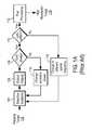
- FIG. 1Billustrates a conventional SAO system
- selective excitation (or illumination) 104is applied to an imaging target 102 , and the light scattered or fluoresced from the imaging target 102 is captured by optical imaging 106 .
- the imaging target 102can be composed of micro-particles in a randomly or regularly distributed pattern.
- Selective excitation (or illumination) 104may be applied to the imaging target 102 by an illumination apparatus (not shown in FIGS. 1A and 1B ) that is configured to cause interference 122 of two or more light beams 131 , 132 on the imaging target 102 .
- the excitationis selective or patterned, unlike uniform illumination used in conventional optical imaging techniques. For example, two beams 131 , 132 may overlay or interfere on an imaging-target plane 102 to produce a two-dimensional (2D) sinusoidal excitation pattern.
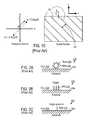
- FIG. 1Cillustrates an example of a selective excitation pattern in the spatial domain and the frequency domain.
- the exemplary selective excitation pattern 140 in the spatial domainis generated by interference of two beams 131 , 132 on the imaging-target plane 102 , resulting in a 2D sinusoidal excitation pattern.
- the angle ( ⁇ ) between the two beams 131 , 132determines the pitch 143 of the pattern, which represents the spacing or periodicity of 2D sinusoidal fringe pattern 140 . More specifically, the pitch 143 is substantially inversely proportional to sin( ⁇ ).
- the orientation ⁇ of the patternrepresents the amount of angular rotation of the 2D sinusoidal fringes 140 compared to its reference pattern, which in this example of FIG.
- the orientation ⁇can be described as follows: if u is the normal vector of the plane formed by the two beams 131 , 132 and if the projected vector of u on the imaging plane 102 is called v, then the orientation ⁇ of the sinusoidal pattern 140 is the angular orientation of the vector v with respect to the frame of reference.
- the “phase” of the patternis the periodic position of the 2D sinusoid with respect to the frame of reference.
- the range of the phases of the 2D sinusoid excitation patternwill be a value between 0 and 2 ⁇ .
- the different phasescan be obtained by changing optical path length of one beam.
- the 2D sinusoid excitation pattern in the spatial domaincan be shown as a conjugate pair k i , k i ′ in the corresponding frequency domain (k-space).
- Each conjugate pair in the k-spacecorresponds to the pitch 143 and orientation ⁇ of the corresponding 2D sinusoid pattern.
- the pitch 143 of the 2D sinusoid pattern 140is determined by the radial distance r of the k-space point—more precisely, the pitch 143 is substantially the inverse of the radial distance r in the frequency domain.
- the orientation ⁇is the angle ⁇ of the k-space points in a radial coordinate system in the frequency domain.
- a number of different excitation patternsmay be generated by changing the pitch 143 of the 2D sinusoid pattern (or the angle ( ⁇ ) between the two beams 131 , 132 ) and changing the orientation ⁇ of the 2D sinusoid pattern, with each different pair of pitch 143 and orientation ⁇ of the 2D sinusoid pattern in the spatial domain corresponding to a different conjugate pair (radial distance r and orientation ⁇ ) in the k-space (frequency) domain.
- the excited target 102emits signals (or photons), and the signals are captured in optical imaging system 106 including an objective lens 124 and an imaging sensor (or imager) 126 .
- the emitted signalwill have a wavelength ⁇ E .
- the imaging sensor 126can be a charge-coupled device (CCD), complementary metal-oxide-semiconductor (CMOS) image sensor, or any other photon detectors in a matrix or array format including a plurality of pixels m. Note that, in some applications, the emitted signals from the target 102 may be directly captured by the imager 126 without going through the objective lens 124 .
- CCDcharge-coupled device
- CMOScomplementary metal-oxide-semiconductor
- step 108it is determined 108 whether the images corresponding to all the phases of the 2D sinusoid excitation pattern were obtained. If images corresponding to all the phases of the 2D sinusoid excitation pattern were not obtained in step 108 , the excitation phase is changed 114 and steps 104 , 106 , 108 are repeated for the changed excitation phase. If images corresponding to all the phases of the 2D sinusoid excitation pattern were obtained in step 108 , then it is determined 110 whether the images corresponding to all the 2D sinusoid selective excitation patterns were obtained.
- the excitation patternis changed by using a different spatial frequency (e.g., changing the pitch 143 and the orientation ⁇ of the 2D sinusoid pattern) and steps 104 , 106 , 108 , 114 are repeated for the next selective excitation pattern.
- a different spatial frequencye.g., changing the pitch 143 and the orientation ⁇ of the 2D sinusoid pattern
- the captured imagesare sent to a computer for SAO post processing 112 and visualization.
- the resolution of the SAO imaging systemis determined by the numerical aperture NA of the lens 124 , the wavelength ⁇ E of the emitted light, and the pixel size.
- the resolution of the imaging systemis beyond what can be achieved by the numerical aperture NA of the lens 124 , the wavelength ⁇ E of the emitted light, and the pixel size.
- 1Aare raw images RI i with a resolution lower than (insufficient for) the resolution needed to resolve the objects on the imaging target 102 .
- multiple sets of the lower resolution raw images RI iare captured for different excitation phases and spatial frequencies (excitation patterns) to obtain the complete raw image set 128 , which then goes through SAO post-processing 112 to synthesize the final image FI that has a resolution higher than the resolution of the raw images RI i .
- the resolution of the final image FI obtained by SAO post-processingis sufficient for resolution of the objects on the imaging target 102 .
- the methodology for SAO post-processing 112 for synthesizing high resolution images FI from lower resolution raw images RI iis well known.
- Raw images RIiare converted into k-space information of the high resolution images FI, and this information is Fourier transformed to synthesize or reconstruct the high resolution images FI.
- SAO post-processing methodologycan be found in U.S. Pat. No. 6,016,196, issued on Jan. 18, 2000 to Mermelstein, entitled “Multiple Beam Pair Optical Imaging,” which is incorporated by reference herein.
- nucleic acidherein includes both DNA and RNA.
- DNA or RNA sequencingsingle molecule or amplified clones of a DNA template (collectively referred to as “microparticle”) are immobilized onto a planar substrate. The array of microparticles then goes through multiple cycles of chemical reaction and optical detection.
- FIGS. 2A, 2B, and 2Cillustrate different types of individual sequencing microparticles that can be used for DNA sequencing.
- FIG. 2Aillustrates an individual microparticle 202 formed by a 1-micrometer diameter bead 208 covered with clonal DNA molecules 210 that have been previously amplified by a water-in-oil emulsion PCR technique.
- the bead 208is attached directly to the substrate 204 in fluid 206 .
- FIG. 2Billustrates an individual microparticle 202 as a cluster of clonal DNA molecules 210 attached to the substrate 204 and placed in fluid 206 .
- the DNA molecules 210have been previously amplified by a bridge amplification technique.
- FIG. 2Cillustrates an individual microparticle as a single DNA molecule 210 attached to the substrate 204 and placed in fluid 206 .
- the single DNA molecule 210is sequenced without amplification.
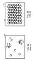
- the distribution of DNA microparticlescan be random or regular.
- FIGS. 3A and 3Billustrate some examples of the distribution of DNA microparticles.
- ⁇ xis defined to be the spatial resolution of an imaging system (i.e., ⁇ x is the minimum distance of two point objects that can be resolved by the imaging system)
- ⁇ xis typically designed to be about half of the distance between adjacent microparticles 202 (see FIG. 3A ).
- SAO imagingis promising since it can image a large area using a low magnification lens and camera without sacrificing resolution.
- the resolution of SAO imagingis obtained from the high resolution illumination patterns and post-processing.
- SAOrequires selective excitation to be repeated for a number of selective excitation patterns.
- Conventional SAO imaginguses a large number of SAO excitation patterns, often including many redundant or even irrelevant illumination patterns.
- the number of excitation patterns in conventional SAOis merely determined based on the hardware architecture of the illumination system, without regard to other factors.
- the large number of excitation patterns in conventional SAOmakes it impractical for use in DNA sequencing, as conventional SAO does not offer the cost and throughput benefit in DNA sequencing compared to conventional optics.
- Embodiments of the present inventioninclude a method for synthetic aperture optics (SAO) that minimizes the number of selective excitation patterns used to illuminate the imaging target based on the target's physical characteristics corresponding to spatial frequency content from the illuminated target and/or one or more parameters of the optical imaging system used for SAO.
- SAOsynthetic aperture optics
- Embodiments of the present inventionalso include an SAO apparatus that includes a plurality of interference pattern generation modules that are arranged in a half-ring shape.
- an SAO methodcomprises illuminating the target including one or more objects with a predetermined number (N) of selective excitation patterns, where the number (N) of selective excitation patterns is determined based upon the objects' physical characteristics corresponding to spatial frequency content from the illuminated target, optically imaging the illuminated target at a resolution insufficient to resolve the objects on the target, and processing optical images of the illuminated target using information on the selective excitation patterns to obtain a final image of the illuminated target at a resolution sufficient to resolve the objects on the target.
- the number (N) of selective excitation patternscorresponds to the number of k-space sampling points in a k-space sampling space in a frequency domain, with the extent of the k-space sampling space being substantially proportional to an inverse of a minimum distance ( ⁇ x) between the objects that is to be resolved by SAO, and with the inverse of the k-space sampling interval between the k-space sampling points being less than a width (w) of a detected area captured by a pixel of a system for said optical imaging.
- an SAO apparatuscomprises a plurality of interference pattern generation modules (IPGMs), with each IPGM configured to generate a pair of light beams that interfere to generate a selective excitation pattern on the target at a predetermined orientation and a predetermined pitch, and with the IPGMs arranged in a half-ring shape.
- the SAO apparatusalso comprises an optical imaging module configured to optically image the illuminated target at a resolution insufficient to resolve the objects on the target. The optical image of the illuminated target is further processed using information on the selective excitation patterns to obtain a final image of the illuminated target at a resolution sufficient to resolve the target.
- the number of IPGMsis equal to the number of selective excitation patterns used for performing SAO on the target.
- the IPGMsmay be placed substantially symmetrically on a monolithic structure that has the half-ring shape.
- an optimized, minimum number of excitation patternsare used in SAO, thereby enabling SAO to be used with applications such as DNA sequencing that requires massive parallelization of SAO imaging in a short amount of time to make DNA sequencing with SAO commercially feasible.
- dramatic increase of throughput and reduction of cost for DNA sequencingcan be achieved by using SAO according to the present invention.
- FIG. 1Aillustrates a conventional SAO method.
- FIG. 1Billustrates a conventional SAO system.
- FIG. 1Cillustrates an example of a selective excitation pattern in the spatial domain and the frequency domain.
- FIGS. 2A, 2B, and 2Cillustrate different types of individual sequencing microparticles that can be used for DNA sequencing.
- FIGS. 3A and 3Billustrate some examples of the distribution of DNA microparticles.
- FIG. 4illustrates an SAO method, according to one embodiment.
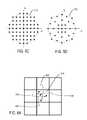
- FIG. 5Aillustrates the k-space sampling points (selective excitation patterns) used in SAO, according to one embodiment.
- FIG. 5Billustrates the selection of the k-space sampling interval used in SAO, according to one embodiment.
- FIG. 5Cillustrates using selective excitation patterns corresponding to k-space sampling points within a circular region, according to one embodiment.
- FIG. 5Dillustrates reducing the number of k-space sampling points by sparse k-space sampling, according to one embodiment.
- FIG. 6Aillustrates how aliasing occurs in SAO by use of a pixel field of view (PFOV) smaller than the detected area, according to one embodiment.
- PFOVpixel field of view
- FIG. 6Billustrates how the actual signal at a pixel of an imaging system may be determined by unfolding the measured signal at the pixel to remove aliasing, according to one embodiment.
- FIG. 6Cillustrates a method of unfolding the measured signal at the pixel to remove aliasing, according to one embodiment.
- FIG. 7Aillustrates a structured illumination apparatus for selectively exciting the microparticles, according to one embodiment.
- FIG. 7Billustrates the arrangement of the illumination pattern generation modules in a half-ring structure, according to one embodiment.
- FIG. 7Cillustrates the internal structure of an illumination pattern generation module, according to one embodiment.
- FIG. 7Dillustrates the internal structure of an illumination pattern generation module, according to another embodiment.
- Synthetic aperture optics (SAO) imaging methodminimizes the number of selective excitation patterns used to illuminate the imaging target, based on the target's physical characteristics corresponding to spatial frequency content from the illuminated target and/or one or more parameters of the optical imaging system used for SAO.
- Embodiments of the present inventionalso include an SAO apparatus that is optimized to perform the SAO method according to the present invention.
- the SAO apparatusincludes a plurality of interference pattern generation modules that are arranged in a half-ring shape, each of which generates one selective excitation pattern for SAO.
- FIG. 4illustrates an SAO method, according to one embodiment.
- selective excitation (or illumination) 104is applied to an imaging target 102 , and the light scattered or fluoresced from the imaging target 102 is captured by optical imaging 106 .
- the imaging target 102is assumed to be a DNA microparticle such as those illustrated in FIGS. 2A-2C, 3A, and 3B .
- selective excitation 104is applied to the imaging target 102 by an illumination apparatus that is configured to cause interference of two light beams on the imaging target 102 .
- the excited target 102emits signals (or photons), and the emitted signals are captured in an optical imaging system 106 including an objective lens and an imaging sensor (or imager). Then, it is determined 408 whether the images corresponding to all M phases of the 2D sinusoid excitation pattern were obtained. If images corresponding to all the phases of the 2D sinusoid excitation pattern were not obtained in step 408 , the excitation phase is changed 402 and steps 104 , 106 , 408 are repeated for the changed excitation phase. If images corresponding to all the phases of the 2D sinusoid excitation pattern were obtained in step 408 , then it is determined 410 whether the images corresponding to all the 2D sinusoid selective excitation patterns were obtained.
- the excitation patternis changed by using a different spatial frequency (e.g., changing the pitch 143 and the orientation ⁇ of the 2D sinusoid pattern) and steps 104 , 106 , 408 , 402 , 410 , 404 are repeated for the next selective excitation pattern. Then, if images corresponding to all the 2D sinusoid excitation patterns were obtained in step 410 , then the captured images are sent to a computer for SAO post processing 412 and visualization to obtain the high-resolution images 114 of the imaging target 102 from the captured lower resolution raw images.
- a different spatial frequencye.g., changing the pitch 143 and the orientation ⁇ of the 2D sinusoid pattern
- the raw images captured by optical imaging 106have a resolution insufficient to resolve the objects on the imaging target 102
- the high resolution image 114 reconstructed by SAO post-processing 412have a resolution sufficient to resolve the objects on the imaging target 102 .
- the SAO method of the present inventionuses an optimized number N of selective excitation patterns and an optimized number M of excitation phases of each selective excitation pattern, so that SAO can be used to image targets such as DNA microparticles in a massively parallel manner within a short amount of time.
- the number of selective excitation patterns used in conventional SAOis determined merely by the hardware characteristics of the illumination system, independent and without consideration of the imaging target or the imaging system (objective lens and camera).
- the number of k-space sampling points corresponding to the selective excitation patterns in conventional SAOwas not optimized, and has many redundant and sometimes irrelevant k-space sampling points.
- SAOuses selective excitation patterns whose number N is optimized and minimized as a function of the imaging target's physical characteristics corresponding to spatial frequency content (e.g., the size, shape, and/or spacing of the objects on the imaging target).
- SAO according to the embodiments hereinmay also use selective excitation patterns whose number N is optimized alternatively or additionally as a function of various parameters of the imaging system (e.g., magnification (Mag) of the objective lens, numerical aperture (NA) of the objective lens, wavelength ⁇ E of the light emitted from the imaging target, and/or effective pixel size p of the pixel sensitive area of the CCD, etc.).
- FIG. 5Aillustrates the k-space sampling points (selective excitation patterns) used in SAO, according to one embodiment.
- the CCD imaging areahas a square shape and thus a square shaped k-space sampling space 500 for SAO is also assumed, although the description for FIG. 5A below can be applied to a non-square shaped (e.g., rectangular) k-space sampling space as well.
- the k-space sampling space 500has an area of FOV 2 , with the extent of the k-space sampling space in each of the horizontal and vertical directions being FOV.
- FOVstands for the k-space field of view.
- FOVIn the k-space frequency domain, FOV should be equal to (1/ ⁇ x), where ⁇ x the spatial resolution of an imaging system (i.e., ⁇ x is the minimum distance of two point objects that can be resolved by the imaging system).
- ⁇ xthe spatial resolution of an imaging system
- ⁇ xthe minimum distance of two point objects that can be resolved by the imaging system.
- Each conjugate pair 502 , 506 and its DC point 504correspond to one selective excitation pattern for SAO as used with the present invention.
- the number of selective excitation patterns used in SAOcorresponds to the number of conjugate pairs of k-space points in the k-space sampling space 500 (FOV ⁇ FOV).
- ⁇ k xis the k-space sampling interval, and is equal to (1/PFOV) where PFOV is the pixel field of view.
- Nfloor( L/ 2) (Equation 1)
- PFOVis the extent in the reciprocal (or Fourier) space of the sampling space (k-space) to be reconstructed from the samples.
- FIG. 5Billustrates the selection of the k-space sampling interval used in SAO, according to one embodiment.
- the imaging target sizedetermines the required spatial resolution ⁇ x.
- the detected area w(x)i.e., the area captured by the pixel
- the detected area w(x)can be represented as the convolution of the pixel-sensitivity function p(x) (e.g., the rectangular function with width p) and the point-spread function (PSF) h(x) of the lens (e.g., a bell-shaped curve).
- the width wcan be defined as the 1/e 2 width of detected area w(x). Since the PSF of the lens is determined by the NA of the lens, the extent of the detected area (w) and the weighting over the detected area (i.e., the effective sensitivity profile over the detected area) are the function of the magnification (Mag) of the lens, numerical aperture (NA) of the lens, and the CCD pixel size (Z).
- the k-space sampling spaceis determined by the desired spatial resolution ⁇ x and is dictated by the imaging target. DNA microparticles typically have a very small size, resulting in a large k-space sampling space.
- the k-space sampling interval ⁇ k xis set without regard to the physical characteristics of the imaging target or the parameters of the imaging system, and is rather just set randomly according to whatever interval allowed by the SAO illumination system. This made the number of k-space points and the resulting selective excitation patterns prohibitively large for use in DNA sequencing applications using SAO, because of the high cost and low throughput of DNA sequencing using such large number of selective excitation patterns in SAO.
- SAOuse selective excitation patterns whose number N is optimized as a function of the imaging target's physical characteristics corresponding to spatial frequency content (e.g., the size, shape, and/or spacing of the imaging target).
- the pixel field of view PFOVis selected to be smaller than the extent (w) of the detected area, i.e., PFOV ⁇ w.
- PFOVa small PFOV results in a larger k-space sampling interval ⁇ k x , thereby reducing the number (L) of k-space points in the k-space sampling space 500 and the resulting number (N) of selective excitation patterns for use in SAO.
- PFOVsmaller than the extent (w) of the detected area causes aliasing in the high resolution image obtained from SAO, but such aliasing can be removed using the method as described below with reference to FIG. 6C .
- the PFOVmay be set to be equal to or larger than the extent (w) of the detected area, thereby preventing aliasing from occurring in the high resolution image obtained from SAO.
- one conjugate pair 502 , 506 of k-space pointscorresponds to one SAO interference pattern generation module that produces a specific pitch and orientation of one selective excitation pattern.
- the DC point 504corresponds to the signal offset of the 2D sinusoid selective excitation pattern.
- each interference pattern generation moduleproduces a pattern with only two different phases, except one module that produces pattern with three different phases to acquire the DC point 504 .
- the optimal phase differencemay be 0, 120, and 240 degrees.
- the optimal phase differencemay be 0 and 90 degrees.
- the SAOuses selective excitation patterns corresponding to the k-space sampling points within the circular region 512 , as shown in FIG. 5C .
- FIG. 5Dillustrates reducing the number of k-space sampling points by sparse k-space sampling, according to one embodiment.
- Conventional SAO methodsdo not utilize frequency information of the objects in the image scene. Solid objects such as beads used in microparticles have much less energy in the high spatial-frequencies compared to the low frequencies. Therefore, under-sampling in the high spatial frequencies is more tolerable than under-sampling in the low spatial frequency region.
- the number (N) of selective excitation patternsis further reduced by non-uniform or variable-density sampling in the Fourier space as shown in FIG. 5D .
- the penalty for not meeting the Nyquist sampling rate in high spatial frequenciesis tolerable in SAO for DNA sequencing applications, and thus SAO according to the embodiments herein relaxes the Nyquist sampling criteria in the higher-frequencies, thereby reducing the number of selective excitation patterns by almost half of what would be required with uniform sampling.
- the number of k-space samples in the embodiment of FIG. 5Dis only 54% of the number of k-space samples in the embodiment of FIG. 5C .
- FIG. 6Aillustrates how aliasing occurs in SAO by use of a pixel field of view smaller than the detected area, according to one embodiment.
- PFOVpixel field of view
- FIG. 6Billustrates how the actual signal at a pixel of an imaging system may be determined by unfolding the measured signal at the pixel to remove aliasing, according to one embodiment.
- s k,irepresents the actual or ideal signal of the object at the k-th sub-pixel locations within the i-th CCD pixel CCD i .
- the weighting function w(x)can be represented as the convolution of the pixel-sensitivity function p(x) (e.g., the rectangular function with width p) and the point-spread function (PSF) h(x) of the lens (e.g., a bell-shaped curve).
- PSFpoint-spread function
- yAx
- y[m k,1 , . . . , m k,2 , . . . ]
- x[s k,1 , s k,2 , . .
- Ais a matrix with elements being zeros and values of the weighting function (e.g., ⁇ , ⁇ , and ⁇ ).
- non-rectilinear sampling patterne.g., variable-density, radial sampling, etc.
- the point-spread-functioni.e., impulse response
- FIG. 6Cillustrates a method of unfolding the measured signal at the pixel to remove aliasing, according to one embodiment.
- the steps 652 , 654 , 656together constitute the post-processing steps for SAO.
- post-processingincludes only the regular SAO reconstruction 652 to generate the high spatial resolution image 653 from the low resolution images (M ⁇ N) 650 obtained from selective excitation of the imaging target.
- post-processingincludes the “unfolding” step 670 to remove aliasing from the high spatial resolution image 653 that contains aliasing resulting from using PFOV smaller than the extent (w) of the detected area for selective excitation.
- “unfolding” as explained hereincan also be used to improve the SAO image reconstruction quality even when PFOV larger than or equal to the extent (w) of the detected area is used for selective excitation in SAO.
- the reconstructed pixelsare simply cropped (to the width being p) and stitched together. This way of “crop and stitch” still does not undo the apodization caused by the weighting function w(x).
- FIG. 7Aillustrates a structured illumination apparatus for selectively exciting the microparticles, according to one embodiment.
- the illumination apparatus shown in FIG. 7Ais merely exemplary, and various modifications may be made to the configuration of the illumination apparatus for SAO according to the present invention.
- the example illumination apparatus in FIG. 7Ashows only two interference pattern generation modules (IPGM) 712 , 713 for simplicity of illustration, but for real DNA sequencing applications there would be a larger number of IPGMs.
- IPGMinterference pattern generation modules
- Each IPGMis in modular form and is configured to generate one selective excitation pattern at a given pitch and orientation, corresponding to one conjugate pair of the k-space sampling points.
- the structured illumination apparatus 700generates multiple mutually-coherent laser beams, the interference of which produces interference patterns. Such interference patterns are projected onto the microparticle array substrate 204 and selectively excite the DNA microparticles 202 . Using the interference of multiple laser beams to generate the interference patterns is advantageous for many reasons. For example, this enables high-resolution excitation patterns with extremely large FOV and DOF.
- the structured illumination apparatus of FIG. 7Ais described herein with the example of generating excitation patterns for DNA microparticles, it should be noted that the structured illumination apparatus of FIG. 7A can be used for any other type of application to generate excitation patterns for imaging any other type of target.
- the structured illumination apparatus 700includes a laser 702 , a beam splitter 704 , shutters 705 , 707 , fiber couplers 708 , 709 , a pair of optical fibers 710 , 711 , and a pair of interference pattern generation modules (IPGMs) 712 , 713 .
- IPGMsinterference pattern generation modules
- each IPGM 712 , 713generates an interference pattern (selective excitation pattern) that corresponds to one conjugate pair of k-space sampling points.
- the beam 703 of the laser 702is split by the beam splitter 704 into two beams 740 , 742 .
- a pair of high-speed shutters 705 , 707is used to switch each beam 740 , 742 “on” or “off” respectively, or to modulate the amplitude of each beam 740 , 742 , respectively.
- Such switched laser beamsare coupled into a pair of polarization-maintaining optical fibers 711 , 710 via fiber couplers 709 , 708 .
- Each fiber 711 , 710is connected to a corresponding interference pattern generation module 713 , 712 , respectively.
- the interference pattern generation module 713includes a collimating lens 714 ′, a beam splitter 716 ′, and a translating mirror 718 ′, and likewise the interference pattern generation module 712 includes a collimating lens 714 , a beam splitter 716 , and a translating mirror 718 .
- the beam 744 from the optical fiber 710is collimated by the collimating lens 714 and split into two beams 724 , 726 by the beam splitter 716 .
- the mirror 718is translated by an actuator 720 to vary the optical path-length of the beam 726 .
- an interference pattern 722is generated on the substrate 204 in the region of overlap between the two laser beams 724 , 726 , with the phase of the pattern changed by varying the optical path-length of one of the beams 726 (i.e., by modulating the optical phase of the beam 726 by use of the translating mirror 718 ).
- the beam 746 from the optical fiber 711is collimated by the collimating lens 714 ′ and split into two beams 728 , 730 by the beam splitter 716 ′.
- the mirror 718 ′is translated by an actuator 720 ′ to vary the optical path-length of the beam 728 .
- the interference pattern 722is generated on the substrate 204 in the region of overlap between the two laser beams 728 , 730 , with the pattern changed by varying the optical path-length of one of the beams 728 (i.e., by modulating the optical phase of the beam 728 by use of the translating mirror 718 ′).
- each IPGM 712 , 713is implemented in modular form according to the embodiments herein, and one IPGM produces an interference pattern corresponding to one conjugate pair of k-space points.
- This modularized one-to-one relationship between the IPGM and the k-space pointsgreatly simplifies the hardware design process for SAO according to the embodiments herein.
- the SAO hardwareis simply changed by increasing or decreasing the number of IPGMs in a modular manner.
- conventional SAO apparatusesdid not have discrete interference pattern generation modules but had a series of split beams producing as many multiple interferences as possible.
- Such conventional way of designing SAO apparatusesproduced non-optimized or redundant patterns, slowing down and complicating the operation of the SAO system.
- the amplitude, polarization, direction, and wavelength, in addition to or instead of the optical amplitude and phase, of one or more of the beams 724 , 726 , 728 , 730can be modulated to change the excitation pattern 722 .
- the structured illuminationcan be simply translated with respect to the microparticle array to change the excitation pattern.
- the microparticle arraycan be translated with respect to the structured illumination to change the excitation pattern.
- optical modulatorscan be used in addition to or instead of the translating mirrors 718 , 718 ′, such as acousto-optic modulators, electro-optic modulators, a rotating window modulated by a galvanometer and micro-electro-mechanical systems (MEMS) modulators.
- MEMSmicro-electro-mechanical systems
- FIG. 7Ais described herein as using a laser 702 as the illumination source for coherent electro-magnetic radiation, other types of coherent electro-magnetic radiation sources such as an SLD (super-luminescent diode) may be used in place of the laser 702 .
- SLDsuper-luminescent diode
- FIG. 7Aillustrates use of four beams 724 , 726 , 728 , 730 to generate the interference pattern 722
- larger number of laser beamscan be used by splitting the source laser beam into more than two beams. For example, 64 beams may be used to generate the interference pattern 722 .
- the beam combinationsdo not need to be restricted to pair-wise combinations.
- three beams 724 , 726 , 728 , or three beams 724 , 726 , 730 , or three beams 724 , 728 , 730 , or three beams 726 , 729 , 730 , or all four beams 724 , 726 , 728 , 730can be used to generate the interference pattern 722 .
- a minimal set of beam combinations(two beams) is chosen as necessary to maximize speed.
- the beamscan be collimated, converging, or diverging.
- additional general background information on generating interference patterns using multiple beam pairscan be found in (i) U.S. Pat. No. 6,016,196, issued on Jan. 18, 2000 to Mermelstein, entitled “Multiple Beam Pair Optical Imaging,” (ii) U.S. Pat. No. 6,140,660, issued on Oct. 31, 2000 to Mermelstein, entitled “Optical Synthetic Aperture Array,” and (iii) U.S. Pat. No. 6,548,820, issued on Apr. 15, 2003 to Mermelstein, entitled “Optical Synthetic Aperture Array,” all of which are incorporated by reference herein.
- FIG. 7Billustrates the arrangement of the illumination pattern generation modules in a half ring structure according to one embodiment.
- multiple IPGMsIPGM 1 , IPGM 2 , . . . , IPGM N
- IPGMs 712 , 713FIG. 7A
- the half-ring structure 762is fixed on the system table 768 .
- the N IPGMsgenerate N selective excitation patterns for SAO on the imaging target 102
- the scattered or fluoresced light 752is passed through objective lens 124 and captured 756 by camera 126 which may be a CCD camera.
- IPGMs in the embodiment of FIG. 7Benable a monolithic and compact holding structure that has multiple benefits for enabling the SAO system to be used for DNA sequencing applications, compared to conventional optical-bench SAO systems where each optical component is individually mounted on its holding structure.
- the monolithic structure 762enables the IPGM arrangement to be compact and symmetric, and this compact, symmetric, and monolithic structure preserves more stable channel-to-channel and beam-to-beam geometry against mechanical and thermal distortions.
- the compact monolithic structure 762is also less susceptible to non-flatness or torsional and bending modes of the optical table 768 , and the symmetric arrangement of the IPGMs around the half-ring structure 762 makes the effect of heat contraction or expansion less detrimental to the beam geometry, i.e., the channel-to-channel or beam-to-beam angles of laser beams are changed less compared to a non-symmetric structure.
- the compact designshortens the travel distances of the laser beam in air, making it easy to prevent air disturbances affecting the stability of the interference pattern that may cause the effective optical path length to change resulting in change of the interference fringe position. Such stability allows more accurate calibration of the beam geometry.
- the imaging modulei.e., camera 126 and objective lens 124
- illumination structurei.e., the half-ring 762
- the imaging target 102to be placed on one stiff structure (e.g., optical table) 768 .
- FIG. 7Cillustrates the internal structure of an illumination pattern generation module, according to one embodiment.
- the embodiment of FIG. 7Chas a rotating window 760 in IPGM 750 that is placed after the mirror 762 .
- the beam 770 from the optical fiber 710is collimated by the collimating lens 754 and the collimated beam 744 is split into two beams 773 , 774 by the beam splitter 756 .
- Beam 773is reflected by mirror 758 and the reflected beam 778 is projected onto the imaging target to generate the interference pattern 780 .
- Beam 774is reflected by mirror 762 and the optical path-length of the reflected beam 776 is modulated by optical window 760 that is rotated, using a galvanometer, thereby modulating the optical phase of the corresponding beam 776 and generating a modulated beam 777 .
- the interference pattern 780is generated in the region of overlap between the two laser beams 777 , 778 , with the pattern changed by varying the optical path-length of one of the beams 777 .
- the width W IPGM and the size of IPGM 750can be reduced, as compared to the embodiment of FIG. 7A and FIG. 7D illustrated below.
- the half-ring shaped structure 762 holding the IPGMscan be made more compact, since the width W IPGM of the IPGM directly affects the radius of the half-ring, for example, as shown in FIG. 7B .
- FIG. 7Dillustrates the internal structure of an illumination pattern generation module, according to another embodiment.
- IPGMs in the embodiments of FIGS. 7A and 7Cmay produce two beams that do not have equal path length between the interfering point at the imaging target and the splitting point (i.e., the beam splitter).
- the non-equal path lengthmay significantly reduce the sinusoidal contrast if a relatively short coherent-length laser is used and also limit the applicability of the SAO system to only a specific wavelength (e.g., 532 nm green laser) since only a small number of lasers with specific wavelengths have a sufficiently long coherent-length that can be used with such non-equal-path IPGMs for good sinusoidal contrast.
- a specific wavelengthe.g., 532 nm green laser
- the laser beam 744is split into beams 781 , 780 by beam splitter 756 .
- Beam 781is reflected by mirror 782 and its optical path-length is modulated by rotating window 760 to generate beam 788 .
- beam 780is reflected twice by two mirrors 784 , 787 to generate the reflected beam 789 .
- Beam 788 and 789eventually interfere at the imaging target to generate the selective excitation patterns.
- the optical path 744 - 780 - 785 - 789is configured to have a length substantially equal to the length of the optical path 781 - 783 - 788 .
- This equal-path schemeallows lasers with short coherent lengths to be used to generate interference patterns with high contrast.
- this equal-path schemeenables the SAO system to be used with wavelengths other than 532 nm, thus making multiple-color SAO practical.
Landscapes
- Physics & Mathematics (AREA)
- Engineering & Computer Science (AREA)
- General Physics & Mathematics (AREA)
- Optics & Photonics (AREA)
- Theoretical Computer Science (AREA)
- Multimedia (AREA)
- Chemical & Material Sciences (AREA)
- Analytical Chemistry (AREA)
- Health & Medical Sciences (AREA)
- General Health & Medical Sciences (AREA)
- Computer Vision & Pattern Recognition (AREA)
- Life Sciences & Earth Sciences (AREA)
- Biomedical Technology (AREA)
- Molecular Biology (AREA)
- Radiology & Medical Imaging (AREA)
- Quality & Reliability (AREA)
- Nuclear Medicine, Radiotherapy & Molecular Imaging (AREA)
- Medical Informatics (AREA)
- Investigating, Analyzing Materials By Fluorescence Or Luminescence (AREA)
- Microscoopes, Condenser (AREA)
Abstract
Description
N=floor(L/2) (Equation 1),
L=round((FOV/Δkx)2)=round((PFOV/Δx)2) (Equation 2),
Claims (10)
Priority Applications (7)
| Application Number | Priority Date | Filing Date | Title |
|---|---|---|---|
| US12/728,140US9465228B2 (en) | 2010-03-19 | 2010-03-19 | Illumination apparatus optimized for synthetic aperture optics imaging using minimum selective excitation patterns |
| PCT/US2011/028796WO2011116178A1 (en) | 2010-03-19 | 2011-03-17 | Illumination apparatus optimized for synthetic aperture optics imaging using minimum selective excitation patterns |
| US15/059,245US9772505B2 (en) | 2010-03-19 | 2016-03-02 | Illumination apparatus optimized for synthetic aperture optics imaging using minimum selective excitation patterns |
| US15/685,982US10429665B2 (en) | 2010-03-19 | 2017-08-24 | Illumination apparatus optimized for synthetic aperture optics imaging using minimum selective excitation patterns |
| US16/567,710US10802292B2 (en) | 2010-03-19 | 2019-09-11 | Illumination apparatus optimized for synthetic aperture optics imaging using minimum selective excitation patterns |
| US17/020,639US11300801B2 (en) | 2010-03-19 | 2020-09-14 | Illumination apparatus optimized for synthetic aperture optics imaging using minimum selective excitation patterns |
| US17/690,410US11835734B2 (en) | 2010-03-19 | 2022-03-09 | Illumination apparatus optimized for synthetic aperture optics imaging using minimum selective excitation patterns |
Applications Claiming Priority (1)
| Application Number | Priority Date | Filing Date | Title |
|---|---|---|---|
| US12/728,140US9465228B2 (en) | 2010-03-19 | 2010-03-19 | Illumination apparatus optimized for synthetic aperture optics imaging using minimum selective excitation patterns |
Related Child Applications (1)
| Application Number | Title | Priority Date | Filing Date |
|---|---|---|---|
| US15/059,245ContinuationUS9772505B2 (en) | 2010-03-19 | 2016-03-02 | Illumination apparatus optimized for synthetic aperture optics imaging using minimum selective excitation patterns |
Publications (2)
| Publication Number | Publication Date |
|---|---|
| US20110228073A1 US20110228073A1 (en) | 2011-09-22 |
| US9465228B2true US9465228B2 (en) | 2016-10-11 |
Family
ID=44646927
Family Applications (6)
| Application Number | Title | Priority Date | Filing Date |
|---|---|---|---|
| US12/728,140Expired - Fee RelatedUS9465228B2 (en) | 2010-03-19 | 2010-03-19 | Illumination apparatus optimized for synthetic aperture optics imaging using minimum selective excitation patterns |
| US15/059,245ActiveUS9772505B2 (en) | 2010-03-19 | 2016-03-02 | Illumination apparatus optimized for synthetic aperture optics imaging using minimum selective excitation patterns |
| US15/685,982ActiveUS10429665B2 (en) | 2010-03-19 | 2017-08-24 | Illumination apparatus optimized for synthetic aperture optics imaging using minimum selective excitation patterns |
| US16/567,710Expired - Fee RelatedUS10802292B2 (en) | 2010-03-19 | 2019-09-11 | Illumination apparatus optimized for synthetic aperture optics imaging using minimum selective excitation patterns |
| US17/020,639ActiveUS11300801B2 (en) | 2010-03-19 | 2020-09-14 | Illumination apparatus optimized for synthetic aperture optics imaging using minimum selective excitation patterns |
| US17/690,410Active2030-08-14US11835734B2 (en) | 2010-03-19 | 2022-03-09 | Illumination apparatus optimized for synthetic aperture optics imaging using minimum selective excitation patterns |
Family Applications After (5)
| Application Number | Title | Priority Date | Filing Date |
|---|---|---|---|
| US15/059,245ActiveUS9772505B2 (en) | 2010-03-19 | 2016-03-02 | Illumination apparatus optimized for synthetic aperture optics imaging using minimum selective excitation patterns |
| US15/685,982ActiveUS10429665B2 (en) | 2010-03-19 | 2017-08-24 | Illumination apparatus optimized for synthetic aperture optics imaging using minimum selective excitation patterns |
| US16/567,710Expired - Fee RelatedUS10802292B2 (en) | 2010-03-19 | 2019-09-11 | Illumination apparatus optimized for synthetic aperture optics imaging using minimum selective excitation patterns |
| US17/020,639ActiveUS11300801B2 (en) | 2010-03-19 | 2020-09-14 | Illumination apparatus optimized for synthetic aperture optics imaging using minimum selective excitation patterns |
| US17/690,410Active2030-08-14US11835734B2 (en) | 2010-03-19 | 2022-03-09 | Illumination apparatus optimized for synthetic aperture optics imaging using minimum selective excitation patterns |
Country Status (2)
| Country | Link |
|---|---|
| US (6) | US9465228B2 (en) |
| WO (1) | WO2011116178A1 (en) |
Cited By (13)
| Publication number | Priority date | Publication date | Assignee | Title |
|---|---|---|---|---|
| US20170018061A1 (en)* | 2011-09-28 | 2017-01-19 | U.S. Army Research Laboratory Attn: Rdrl-Loc-I | System and processor implemented method for improved image quality and generating an image of a target illuminated by quantum particles |
| US20180107159A1 (en)* | 2015-07-07 | 2018-04-19 | Olympus Corporation | Digital holographic image-taking apparatus |
| US10831012B2 (en) | 2018-06-29 | 2020-11-10 | Illumina, Inc. | Predicting structured illumination parameters |
| US10901202B2 (en) | 2018-09-19 | 2021-01-26 | Illumina, Inc. | Structured illumination of a sample |
| US10928322B2 (en) | 2018-01-24 | 2021-02-23 | Illumina, Inc. | Structured illumination microscopy with line scanning |
| US10996453B2 (en) | 2018-01-16 | 2021-05-04 | Illumina, Inc. | Pattern angle spatial selection structured illumination imaging |
| US11150455B2 (en) | 2018-01-24 | 2021-10-19 | Illumina, Inc. | Reduced dimensionality structured illumination microscopy with patterned arrays of nanowells |
| US11226475B2 (en) | 2018-01-16 | 2022-01-18 | Illumina, Inc. | Dual optical grating slide structured illumination imaging |
| US11366303B2 (en) | 2018-01-30 | 2022-06-21 | Rebus Biosystems, Inc. | Method for detecting particles using structured illumination |
| US11585757B2 (en) | 2018-06-14 | 2023-02-21 | Illumina, Inc. | Device for luminescent imaging |
| US11675175B2 (en) | 2018-01-16 | 2023-06-13 | Illumina, Inc. | Multi-arm structured illumination imaging |
| US11953464B2 (en) | 2018-01-08 | 2024-04-09 | Illumina, Inc. | Semiconductor-based biosensors for base calling |
| US12241833B2 (en) | 2018-01-08 | 2025-03-04 | Illumina, Inc. | Multiplexing of an active sensor detector using structured illumination |
Families Citing this family (14)
| Publication number | Priority date | Publication date | Assignee | Title |
|---|---|---|---|---|
| US8759077B2 (en) | 2007-08-28 | 2014-06-24 | Lightspeed Genomics, Inc. | Apparatus for selective excitation of microparticles |
| US9465228B2 (en)* | 2010-03-19 | 2016-10-11 | Optical Biosystems, Inc. | Illumination apparatus optimized for synthetic aperture optics imaging using minimum selective excitation patterns |
| WO2012145534A1 (en)* | 2011-04-20 | 2012-10-26 | Logos Technologies, Inc. | A flexible driver laser for inertial fusion energy |
| US9386305B2 (en)* | 2011-11-28 | 2016-07-05 | Qualcomm Incorporated | Largest coding unit (LCU) or partition-based syntax for adaptive loop filter and sample adaptive offset in video coding |
| US20140323325A1 (en)* | 2013-03-06 | 2014-10-30 | Marc Beal | Molecular imaging and related methods |
| JP2017064743A (en)* | 2015-09-29 | 2017-04-06 | 株式会社ディスコ | Laser processing equipment |
| JP6546823B2 (en)* | 2015-09-29 | 2019-07-17 | 株式会社ディスコ | Laser processing equipment |
| US10627490B2 (en) | 2016-01-31 | 2020-04-21 | Velodyne Lidar, Inc. | Multiple pulse, LIDAR based 3-D imaging |
| WO2017210418A1 (en) | 2016-06-01 | 2017-12-07 | Velodyne Lidar, Inc. | Multiple pixel scanning lidar |
| EP3593166B1 (en) | 2017-03-31 | 2024-04-17 | Velodyne Lidar USA, Inc. | Integrated lidar illumination power control |
| CN110809704B (en) | 2017-05-08 | 2022-11-01 | 威力登激光雷达美国有限公司 | LIDAR data acquisition and control |
| WO2019018693A2 (en) | 2017-07-19 | 2019-01-24 | Altius Institute For Biomedical Sciences | Methods of analyzing microscopy images using machine learning |
| US10712434B2 (en) | 2018-09-18 | 2020-07-14 | Velodyne Lidar, Inc. | Multi-channel LIDAR illumination driver |
| US11885958B2 (en) | 2019-01-07 | 2024-01-30 | Velodyne Lidar Usa, Inc. | Systems and methods for a dual axis resonant scanning mirror |
Citations (62)
| Publication number | Priority date | Publication date | Assignee | Title |
|---|---|---|---|---|
| US3780217A (en)* | 1972-05-11 | 1973-12-18 | Bendix Corp | Heterodyne imaging device for providing high resolution images |
| US3785262A (en)* | 1969-12-09 | 1974-01-15 | G Stroke | Optical aperture synthesis |
| US4890921A (en)* | 1986-08-11 | 1990-01-02 | The Boeing Company | Scanning interferometer |
| US5041733A (en) | 1987-03-20 | 1991-08-20 | Agency Of Industrial Science & Technology | Method and apparatus for identifying chromosomes or cells |
| US5086341A (en)* | 1989-09-14 | 1992-02-04 | Sony Corporation | Laser scanning apparatus having two, parallel, acousto optic deflectors for the horizontal scan |
| US5341312A (en)* | 1991-09-26 | 1994-08-23 | Eastman Kodak Company | Method for assessing and correcting individual components of a non-monolithic imaging assembly |
| US5406412A (en)* | 1993-06-17 | 1995-04-11 | Visidyne, Inc. | High-resolution synthetic aperture adaptive optics system |
| US5470710A (en) | 1993-10-22 | 1995-11-28 | University Of Utah | Automated hybridization/imaging device for fluorescent multiplex DNA sequencing |
| US5511060A (en)* | 1993-02-26 | 1996-04-23 | Industrial Technology Research Institute | Magneto-optical head with a three prism beam splitter to split a reflected beam into three beams |
| US5674698A (en) | 1992-09-14 | 1997-10-07 | Sri International | Up-converting reporters for biological and other assays using laser excitation techniques |
| US5695934A (en) | 1994-10-13 | 1997-12-09 | Lynx Therapeutics, Inc. | Massively parallel sequencing of sorted polynucleotides |
| US5750341A (en) | 1995-04-17 | 1998-05-12 | Lynx Therapeutics, Inc. | DNA sequencing by parallel oligonucleotide extensions |
| US5751243A (en) | 1990-10-29 | 1998-05-12 | Essex Corporation | Image synthesis using time sequential holography |
| US5763175A (en) | 1995-11-17 | 1998-06-09 | Lynx Therapeutics, Inc. | Simultaneous sequencing of tagged polynucleotides |
| US5780231A (en) | 1995-11-17 | 1998-07-14 | Lynx Therapeutics, Inc. | DNA extension and analysis with rolling primers |
| US5902723A (en) | 1989-06-07 | 1999-05-11 | Dower; William J. | Analysis of surface immobilized polymers utilizing microfluorescence detection |
| US6013445A (en) | 1996-06-06 | 2000-01-11 | Lynx Therapeutics, Inc. | Massively parallel signature sequencing by ligation of encoded adaptors |
| US6016196A (en) | 1997-06-17 | 2000-01-18 | Massachusetts Institute Of Technology | Multiple beam pair optical imaging |
| KR20000004675A (en) | 1998-06-30 | 2000-01-25 | 전주범 | Spatial type hologram data storage system using a multiple piezo optical displacement device |
| US6140660A (en)* | 1999-03-23 | 2000-10-31 | Massachusetts Institute Of Technology | Optical synthetic aperture array |
| US20020051992A1 (en) | 1997-05-23 | 2002-05-02 | Lynx Therapeutics, Inc. | System and apparatus for sequential processing of analytes |
| US20020061529A1 (en) | 1998-05-22 | 2002-05-23 | Lynx Therapeutics, Inc. | System and apparatus for sequential processing of analytes |
| US20020137052A1 (en) | 1994-10-13 | 2002-09-26 | Lynx Therapeutics, Inc. | System and apparatus for sequential processing of analytes |
| US6525875B1 (en)* | 1998-04-15 | 2003-02-25 | Vincent Lauer | Microscope generating a three-dimensional representation of an object and images generated by such a microscope |
| US6539805B2 (en) | 1994-07-19 | 2003-04-01 | Vesuvius Crucible Company | Liquid metal flow condition detection |
| US20030224419A1 (en) | 1997-05-23 | 2003-12-04 | Lynx Therapeutics, Inc. | Data analysis and display system for ligation-based DNA sequencing |
| US6787308B2 (en) | 1998-07-30 | 2004-09-07 | Solexa Ltd. | Arrayed biomolecules and their use in sequencing |
| US6833246B2 (en) | 1999-09-29 | 2004-12-21 | Solexa, Ltd. | Polynucleotide sequencing |
| US20050100932A1 (en) | 2003-11-12 | 2005-05-12 | Helicos Biosciences Corporation | Short cycle methods for sequencing polynucleotides |
| US20050099682A1 (en) | 2000-11-06 | 2005-05-12 | Vincent Lauer | Microscope for diffracting objects |
| US6911345B2 (en) | 1999-06-28 | 2005-06-28 | California Institute Of Technology | Methods and apparatus for analyzing polynucleotide sequences |
| US20050221351A1 (en) | 2004-04-06 | 2005-10-06 | Affymetrix, Inc. | Methods and devices for microarray image analysis |
| US20050286576A1 (en) | 2004-06-23 | 2005-12-29 | Alistair Gill | Apparatus and method for controlling the power of a laser beam |
| US20060012793A1 (en) | 2004-07-19 | 2006-01-19 | Helicos Biosciences Corporation | Apparatus and methods for analyzing samples |
| US20060012784A1 (en) | 2004-07-19 | 2006-01-19 | Helicos Biosciences Corporation | Apparatus and methods for analyzing samples |
| US20060024711A1 (en) | 2004-07-02 | 2006-02-02 | Helicos Biosciences Corporation | Methods for nucleic acid amplification and sequence determination |
| US20060146334A1 (en) | 2002-09-18 | 2006-07-06 | Cluff Julian A | Apparatus for varying the path length of a beam of radiation |
| US7115400B1 (en) | 1998-09-30 | 2006-10-03 | Solexa Ltd. | Methods of nucleic acid amplification and sequencing |
| US7122384B2 (en) | 2002-11-06 | 2006-10-17 | E. I. Du Pont De Nemours And Company | Resonant light scattering microparticle methods |
| US20060263777A1 (en) | 2003-01-27 | 2006-11-23 | Tong William G | Sensitive sensing based on optical optical nonlinear wave mixing |
| US20070014486A1 (en)* | 2005-07-13 | 2007-01-18 | Thomas Schiwietz | High speed image reconstruction for k-space trajectory data using graphic processing unit (GPU) |
| US20070031875A1 (en) | 2005-08-05 | 2007-02-08 | Helicos Biosciences Corporation | Signal pattern compositions and methods |
| US20070070349A1 (en) | 2005-09-23 | 2007-03-29 | Helicos Biosciences Corporation | Optical train and method for TIRF single molecule detection and analysis |
| US20070082562A1 (en)* | 2003-10-30 | 2007-04-12 | Van Der Lee Alexander M | Multi-beam optical scanning device |
| US20070087362A1 (en)* | 2004-02-27 | 2007-04-19 | President And Fellows Of Harvard College | Polony fluorescent in situ sequencing beads |
| US7211390B2 (en) | 1999-09-16 | 2007-05-01 | 454 Life Sciences Corporation | Method of sequencing a nucleic acid |
| US20070099208A1 (en)* | 2005-06-15 | 2007-05-03 | Radoje Drmanac | Single molecule arrays for genetic and chemical analysis |
| US7248338B2 (en) | 2004-03-29 | 2007-07-24 | Fujifilm Corporation | Multi beam exposing device and exposing method using the same |
| US20070231825A1 (en)* | 2000-06-21 | 2007-10-04 | Sukanta Banerjee | Multianalyte molecular analysis using application-specific random particle arrays |
| US20070273863A1 (en)* | 2004-12-17 | 2007-11-29 | The Boeing Company | Ultra-linear signal processing for radar and laser radar |
| US20080140341A1 (en)* | 2006-07-10 | 2008-06-12 | The Board Of Trustees Of The University Of Illinois | Interferometric Synthetic Aperture Microscopy |
| US7397018B1 (en)* | 2005-03-02 | 2008-07-08 | Lockheed Martin Corporation | Amplitude and phase controlled adaptive optics system |
| US20080176145A1 (en)* | 2006-05-30 | 2008-07-24 | Semiconductor Energy Laboratory Co., Ltd. | Method for manufacturing holographic recording medium and method for manufacturing semiconductor device |
| US7405114B2 (en) | 2002-10-16 | 2008-07-29 | Semiconductor Energy Laboratory Co., Ltd. | Laser irradiation apparatus and method of manufacturing semiconductor device |
| US20080315095A1 (en)* | 2004-02-20 | 2008-12-25 | Ebara Corporation | Electron beam apparatus, a device manufacturing method using the same apparatus, a pattern evaluation method, a device manufacturing method using the same method, and a resist pattern or processed wafer evaluation method |
| US20090061505A1 (en)* | 2007-08-28 | 2009-03-05 | Hong Stanley S | Apparatus for selective excitation of microparticles |
| US20090061526A1 (en)* | 2007-08-28 | 2009-03-05 | Hong Stanley S | Nucleic acid sequencing by selective excitation of microparticles |
| US7639909B2 (en)* | 2001-12-06 | 2009-12-29 | Florida Institute Of Technology | Method and apparatus for spatial domain multiplexing in optical fiber communications |
| US20110228068A1 (en)* | 2010-03-19 | 2011-09-22 | Lightspeed Genomics, Inc. | Synthetic aperture optics imaging method using minimum selective excitation patterns |
| US8329560B2 (en)* | 2007-07-24 | 2012-12-11 | Eo Technics Co., Ltd. | Laser processing apparatus and method using beam split |
| US20140323325A1 (en)* | 2013-03-06 | 2014-10-30 | Marc Beal | Molecular imaging and related methods |
| US8929630B2 (en)* | 2009-03-27 | 2015-01-06 | Life Technologies Corporation | Systems and methods for assessing images |
Family Cites Families (14)
| Publication number | Priority date | Publication date | Assignee | Title |
|---|---|---|---|---|
| WO2000065094A2 (en)* | 1999-04-22 | 2000-11-02 | The Albert Einstein College Of Medicine Of Yeshiva University | Assay of gene expression patterns by multi-fluor fish |
| US6515287B2 (en)* | 2000-06-15 | 2003-02-04 | Kla-Tencor Technologies Corporation | Sectored magnetic lens and method of use |
| WO2003021853A2 (en)* | 2001-09-05 | 2003-03-13 | Genicon Sciences Corporation | Apparatus for reading signals generated from resonance light scattered particle labels |
| KR200327028Y1 (en)* | 2003-06-17 | 2003-09-19 | 장시창 | Tool for inspecting the tissue of human body |
| ATE459933T1 (en)* | 2004-11-16 | 2010-03-15 | Illumina Inc | METHOD AND APPARATUS FOR READING CODED MICROBALLS |
| US7967205B2 (en)* | 2005-11-17 | 2011-06-28 | Hand Held Products, Inc. | Optical reading device with programmable parameter control |
| EP2185992B1 (en)* | 2007-09-04 | 2013-07-17 | Apple Inc. | Smart dock for chaining accessories |
| US7949203B2 (en)* | 2007-09-20 | 2011-05-24 | Harris Corporation | Geospatial modeling system providing void inpainting based upon selectable inpainting functions and related methods |
| US8156157B2 (en)* | 2007-09-20 | 2012-04-10 | Harris Corporation | Geospatial modeling system providing windowed geospatial model data inpainting and related methods |
| WO2009126546A1 (en)* | 2008-04-07 | 2009-10-15 | University Of Florida Research Foundation, Inc. | High-precision monolithic optical assemblies and methods for fabrication and alignment thereof |
| US8039776B2 (en)* | 2008-05-05 | 2011-10-18 | California Institute Of Technology | Quantitative differential interference contrast (DIC) microscopy and photography based on wavefront sensors |
| CN102216736B (en)* | 2008-08-26 | 2015-01-14 | 格拉斯哥大学理事会 | Uses of electromagnetic interference patterns |
| US8705043B2 (en)* | 2009-12-14 | 2014-04-22 | Academia Sinica | Height measurement by correlating intensity with position of scanning object along optical axis of a structured illumination microscope |
| US9465228B2 (en)* | 2010-03-19 | 2016-10-11 | Optical Biosystems, Inc. | Illumination apparatus optimized for synthetic aperture optics imaging using minimum selective excitation patterns |
- 2010
- 2010-03-19USUS12/728,140patent/US9465228B2/ennot_activeExpired - Fee Related
- 2011
- 2011-03-17WOPCT/US2011/028796patent/WO2011116178A1/enactiveApplication Filing
- 2016
- 2016-03-02USUS15/059,245patent/US9772505B2/enactiveActive
- 2017
- 2017-08-24USUS15/685,982patent/US10429665B2/enactiveActive
- 2019
- 2019-09-11USUS16/567,710patent/US10802292B2/ennot_activeExpired - Fee Related
- 2020
- 2020-09-14USUS17/020,639patent/US11300801B2/enactiveActive
- 2022
- 2022-03-09USUS17/690,410patent/US11835734B2/enactiveActive
Patent Citations (85)
| Publication number | Priority date | Publication date | Assignee | Title |
|---|---|---|---|---|
| US3785262A (en)* | 1969-12-09 | 1974-01-15 | G Stroke | Optical aperture synthesis |
| US3780217A (en)* | 1972-05-11 | 1973-12-18 | Bendix Corp | Heterodyne imaging device for providing high resolution images |
| US4890921A (en)* | 1986-08-11 | 1990-01-02 | The Boeing Company | Scanning interferometer |
| US5041733A (en) | 1987-03-20 | 1991-08-20 | Agency Of Industrial Science & Technology | Method and apparatus for identifying chromosomes or cells |
| US5902723A (en) | 1989-06-07 | 1999-05-11 | Dower; William J. | Analysis of surface immobilized polymers utilizing microfluorescence detection |
| US5086341A (en)* | 1989-09-14 | 1992-02-04 | Sony Corporation | Laser scanning apparatus having two, parallel, acousto optic deflectors for the horizontal scan |
| US5751243A (en) | 1990-10-29 | 1998-05-12 | Essex Corporation | Image synthesis using time sequential holography |
| US5341312A (en)* | 1991-09-26 | 1994-08-23 | Eastman Kodak Company | Method for assessing and correcting individual components of a non-monolithic imaging assembly |
| US5674698A (en) | 1992-09-14 | 1997-10-07 | Sri International | Up-converting reporters for biological and other assays using laser excitation techniques |
| US5511060A (en)* | 1993-02-26 | 1996-04-23 | Industrial Technology Research Institute | Magneto-optical head with a three prism beam splitter to split a reflected beam into three beams |
| US5406412A (en)* | 1993-06-17 | 1995-04-11 | Visidyne, Inc. | High-resolution synthetic aperture adaptive optics system |
| US5470710A (en) | 1993-10-22 | 1995-11-28 | University Of Utah | Automated hybridization/imaging device for fluorescent multiplex DNA sequencing |
| US6539805B2 (en) | 1994-07-19 | 2003-04-01 | Vesuvius Crucible Company | Liquid metal flow condition detection |
| US5695934A (en) | 1994-10-13 | 1997-12-09 | Lynx Therapeutics, Inc. | Massively parallel sequencing of sorted polynucleotides |
| US6654505B2 (en) | 1994-10-13 | 2003-11-25 | Lynx Therapeutics, Inc. | System and apparatus for sequential processing of analytes |
| US20020137052A1 (en) | 1994-10-13 | 2002-09-26 | Lynx Therapeutics, Inc. | System and apparatus for sequential processing of analytes |
| US5750341A (en) | 1995-04-17 | 1998-05-12 | Lynx Therapeutics, Inc. | DNA sequencing by parallel oligonucleotide extensions |
| US6306597B1 (en) | 1995-04-17 | 2001-10-23 | Lynx Therapeutics, Inc. | DNA sequencing by parallel oligonucleotide extensions |
| US5969119A (en) | 1995-04-17 | 1999-10-19 | Lynx Therapeutics, Inc. | DNA sequencing by parallel olgonucleotide extensions |
| US5763175A (en) | 1995-11-17 | 1998-06-09 | Lynx Therapeutics, Inc. | Simultaneous sequencing of tagged polynucleotides |
| US5780231A (en) | 1995-11-17 | 1998-07-14 | Lynx Therapeutics, Inc. | DNA extension and analysis with rolling primers |
| US6013445A (en) | 1996-06-06 | 2000-01-11 | Lynx Therapeutics, Inc. | Massively parallel signature sequencing by ligation of encoded adaptors |
| US20030077615A1 (en) | 1997-05-23 | 2003-04-24 | Lynx Therapeutics, Inc. | Planar arrays of microparticle-bound polynucleotides |
| US20060051876A1 (en) | 1997-05-23 | 2006-03-09 | Lynx Therapeutics, Inc. | System and apparatus for sequential processing of analytes |
| US20020051992A1 (en) | 1997-05-23 | 2002-05-02 | Lynx Therapeutics, Inc. | System and apparatus for sequential processing of analytes |
| US6831994B2 (en) | 1997-05-23 | 2004-12-14 | Lynx Therapeutics, Inc. | System and apparatus for sequential processing of analytes |
| US6406848B1 (en) | 1997-05-23 | 2002-06-18 | Lynx Therapeutics, Inc. | Planar arrays of microparticle-bound polynucleotides |
| US6806052B2 (en) | 1997-05-23 | 2004-10-19 | Lynx Therapeutics, Inc. | Planar arrays of microparticle-bound polynucleotides |
| US20030224419A1 (en) | 1997-05-23 | 2003-12-04 | Lynx Therapeutics, Inc. | Data analysis and display system for ligation-based DNA sequencing |
| US6016196A (en) | 1997-06-17 | 2000-01-18 | Massachusetts Institute Of Technology | Multiple beam pair optical imaging |
| US6525875B1 (en)* | 1998-04-15 | 2003-02-25 | Vincent Lauer | Microscope generating a three-dimensional representation of an object and images generated by such a microscope |
| US6969488B2 (en) | 1998-05-22 | 2005-11-29 | Solexa, Inc. | System and apparatus for sequential processing of analytes |
| US20020061529A1 (en) | 1998-05-22 | 2002-05-23 | Lynx Therapeutics, Inc. | System and apparatus for sequential processing of analytes |
| KR20000004675A (en) | 1998-06-30 | 2000-01-25 | 전주범 | Spatial type hologram data storage system using a multiple piezo optical displacement device |
| US6787308B2 (en) | 1998-07-30 | 2004-09-07 | Solexa Ltd. | Arrayed biomolecules and their use in sequencing |
| US7115400B1 (en) | 1998-09-30 | 2006-10-03 | Solexa Ltd. | Methods of nucleic acid amplification and sequencing |
| US6548820B1 (en) | 1999-03-23 | 2003-04-15 | Massachusetts Institute Of Technology | Optical synthetic aperture array |
| US6140660A (en)* | 1999-03-23 | 2000-10-31 | Massachusetts Institute Of Technology | Optical synthetic aperture array |
| US6911345B2 (en) | 1999-06-28 | 2005-06-28 | California Institute Of Technology | Methods and apparatus for analyzing polynucleotide sequences |
| US7211390B2 (en) | 1999-09-16 | 2007-05-01 | 454 Life Sciences Corporation | Method of sequencing a nucleic acid |
| US6833246B2 (en) | 1999-09-29 | 2004-12-21 | Solexa, Ltd. | Polynucleotide sequencing |
| US20070231825A1 (en)* | 2000-06-21 | 2007-10-04 | Sukanta Banerjee | Multianalyte molecular analysis using application-specific random particle arrays |
| US20080241936A1 (en)* | 2000-06-21 | 2008-10-02 | Sukanta Banerjee | Multianalyte Molecular Analysis Using Application-Specific Random Particle Arrays |
| US20050099682A1 (en) | 2000-11-06 | 2005-05-12 | Vincent Lauer | Microscope for diffracting objects |
| US20060274408A1 (en) | 2000-11-06 | 2006-12-07 | Vincent Lauer | Microscope for diffracting objects |
| US7639909B2 (en)* | 2001-12-06 | 2009-12-29 | Florida Institute Of Technology | Method and apparatus for spatial domain multiplexing in optical fiber communications |
| US20060146334A1 (en) | 2002-09-18 | 2006-07-06 | Cluff Julian A | Apparatus for varying the path length of a beam of radiation |
| US7405114B2 (en) | 2002-10-16 | 2008-07-29 | Semiconductor Energy Laboratory Co., Ltd. | Laser irradiation apparatus and method of manufacturing semiconductor device |
| US7122384B2 (en) | 2002-11-06 | 2006-10-17 | E. I. Du Pont De Nemours And Company | Resonant light scattering microparticle methods |
| US20060263777A1 (en) | 2003-01-27 | 2006-11-23 | Tong William G | Sensitive sensing based on optical optical nonlinear wave mixing |
| US20070082562A1 (en)* | 2003-10-30 | 2007-04-12 | Van Der Lee Alexander M | Multi-beam optical scanning device |
| US20050100932A1 (en) | 2003-11-12 | 2005-05-12 | Helicos Biosciences Corporation | Short cycle methods for sequencing polynucleotides |
| US7169560B2 (en) | 2003-11-12 | 2007-01-30 | Helicos Biosciences Corporation | Short cycle methods for sequencing polynucleotides |
| US20080315095A1 (en)* | 2004-02-20 | 2008-12-25 | Ebara Corporation | Electron beam apparatus, a device manufacturing method using the same apparatus, a pattern evaluation method, a device manufacturing method using the same method, and a resist pattern or processed wafer evaluation method |
| US20070087362A1 (en)* | 2004-02-27 | 2007-04-19 | President And Fellows Of Harvard College | Polony fluorescent in situ sequencing beads |
| US7248338B2 (en) | 2004-03-29 | 2007-07-24 | Fujifilm Corporation | Multi beam exposing device and exposing method using the same |
| US20050239113A1 (en) | 2004-04-06 | 2005-10-27 | Affymetrix, Inc. | Methods and devices for microarray image |
| US20050221351A1 (en) | 2004-04-06 | 2005-10-06 | Affymetrix, Inc. | Methods and devices for microarray image analysis |
| US20050239115A1 (en) | 2004-04-06 | 2005-10-27 | Affymetrix, Inc. | Methods and devices for microarray image |
| US20050239114A1 (en) | 2004-04-06 | 2005-10-27 | Affymetrix, Inc. | Methods and devices for microarray image analysis |
| US20050286576A1 (en) | 2004-06-23 | 2005-12-29 | Alistair Gill | Apparatus and method for controlling the power of a laser beam |
| US20060024711A1 (en) | 2004-07-02 | 2006-02-02 | Helicos Biosciences Corporation | Methods for nucleic acid amplification and sequence determination |
| US20060012784A1 (en) | 2004-07-19 | 2006-01-19 | Helicos Biosciences Corporation | Apparatus and methods for analyzing samples |
| US20060012793A1 (en) | 2004-07-19 | 2006-01-19 | Helicos Biosciences Corporation | Apparatus and methods for analyzing samples |
| US20070273863A1 (en)* | 2004-12-17 | 2007-11-29 | The Boeing Company | Ultra-linear signal processing for radar and laser radar |
| US7397018B1 (en)* | 2005-03-02 | 2008-07-08 | Lockheed Martin Corporation | Amplitude and phase controlled adaptive optics system |
| US20070099208A1 (en)* | 2005-06-15 | 2007-05-03 | Radoje Drmanac | Single molecule arrays for genetic and chemical analysis |
| US20070014486A1 (en)* | 2005-07-13 | 2007-01-18 | Thomas Schiwietz | High speed image reconstruction for k-space trajectory data using graphic processing unit (GPU) |
| US7916144B2 (en) | 2005-07-13 | 2011-03-29 | Siemens Medical Solutions Usa, Inc. | High speed image reconstruction for k-space trajectory data using graphic processing unit (GPU) |
| US20070031875A1 (en) | 2005-08-05 | 2007-02-08 | Helicos Biosciences Corporation | Signal pattern compositions and methods |
| US20070070349A1 (en) | 2005-09-23 | 2007-03-29 | Helicos Biosciences Corporation | Optical train and method for TIRF single molecule detection and analysis |
| US20080176145A1 (en)* | 2006-05-30 | 2008-07-24 | Semiconductor Energy Laboratory Co., Ltd. | Method for manufacturing holographic recording medium and method for manufacturing semiconductor device |
| US20080140341A1 (en)* | 2006-07-10 | 2008-06-12 | The Board Of Trustees Of The University Of Illinois | Interferometric Synthetic Aperture Microscopy |
| US7643155B2 (en)* | 2006-07-10 | 2010-01-05 | The Board Of Trustees Of The University Of Illinois | Partially coherent illumination for inverse scattering full-field interferometric synthetic aperture microscopy |
| US7602501B2 (en)* | 2006-07-10 | 2009-10-13 | The Board Of Trustees Of The University Of Illinois | Interferometric synthetic aperture microscopy |
| US8329560B2 (en)* | 2007-07-24 | 2012-12-11 | Eo Technics Co., Ltd. | Laser processing apparatus and method using beam split |
| WO2009032510A1 (en) | 2007-08-28 | 2009-03-12 | Lightspeed Genomics, Inc. | Apparatus for selective excitation of microparticles |
| US20090061526A1 (en)* | 2007-08-28 | 2009-03-05 | Hong Stanley S | Nucleic acid sequencing by selective excitation of microparticles |
| US8222040B2 (en)* | 2007-08-28 | 2012-07-17 | Lightspeed Genomics, Inc. | Nucleic acid sequencing by selective excitation of microparticles |
| US20090061505A1 (en)* | 2007-08-28 | 2009-03-05 | Hong Stanley S | Apparatus for selective excitation of microparticles |
| US8759077B2 (en)* | 2007-08-28 | 2014-06-24 | Lightspeed Genomics, Inc. | Apparatus for selective excitation of microparticles |
| US8929630B2 (en)* | 2009-03-27 | 2015-01-06 | Life Technologies Corporation | Systems and methods for assessing images |
| US20110228068A1 (en)* | 2010-03-19 | 2011-09-22 | Lightspeed Genomics, Inc. | Synthetic aperture optics imaging method using minimum selective excitation patterns |
| US8502867B2 (en)* | 2010-03-19 | 2013-08-06 | Lightspeed Genomics, Inc. | Synthetic aperture optics imaging method using minimum selective excitation patterns |
| US20140323325A1 (en)* | 2013-03-06 | 2014-10-30 | Marc Beal | Molecular imaging and related methods |
Non-Patent Citations (18)
| Title |
|---|
| Chinese State Intellectual Property Office, First Office Action, Chinese Application No. 200880104704.6, Dec. 19, 2011, seventeen pages. |
| Cragg, G. et al., "Lateral Resolution Enhancement with Standing Evanescent Waves," Optics Letters, Jan. 1, 2000, vol. 25, No. 1, pp. 46-48. |
| Freimann, R., et al., "Development of a standing-wave fluorescence microscope with high nodal plane flatness," Journal of Microscopy, Sep. 1997, pp. 193-200, vol. 187, Pt. 3. |
| Frohn, J., et al., "Three-dimensional resolution enhancement in fluorescence microscopy by harmonic excitation," Optic Letters, Jun. 1, 2001, pp. 828-830, vol. 26, No. 11. |
| Frohn, J., et al., "True optical resolution beyond the Rayleigh limit achieved by standing wave illumination," PNAS, Jun. 20, 2000, pp. 7232-7236, vol. 97, No. 13. |
| Gustafsson, M.G.L., "Surpassing the lateral resolution limit by a factor of two using structured illumination microscopy," Journal of Microscopy, May 2000, pp. 82-87, vol. 198, Pt. 2. |
| Hong, S., et al., "Lensless focusing with subwavelength resolution by direct synthesis of the angular spectrum," Applied Physics Letters, Jun. 29, 2006, vol. 88, pp. 261107-1-261107-3. |
| Kim, J., et al., "Polony Multiplex Analysis of Gene Expression (PMAGE) in Mouse Hypertrophic Cardiomyopathy," Science, Jun. 8, 2007, pp. 1481-1484, vol. 316, with Supporting Online Material downloaded from the Internet at http://www.sciencemag.org/cgi/data/316/5830/1481/DC1/2 attached. |
| Korean Intellectual Property Office, Office Action, Korean Patent Application No. 10-2010-7004824, Jun. 5, 2012, twelve pages. |
| Korean Intellectual Property Office, Office Action, Korean Patent Application No. 10-2010-7004824, Oct. 21, 2011, eleven pages. |
| PCT International Search Report and Written Opinion, PCT Application No. PCT/US2011/028792, May 26, 2011, seven pages. |
| PCT International Search Report and Written Opinion, PCT Application No. PCT/US2011/028796, May 13, 2011, eight pages. |
| Ryu, J., "Resolution Improvement in Optical Microscopy by Use of Multi-Beam Interferometric Illumination," Ph.D. Dissertation, Massachusetts Institute of Technology, 2003, pp. 3, 7-9, 109-111, and 119-122. |
| Ryu, J., "Resolution Improvement in Optical Microscopy by Use of Multi-Beam Interferometric Illumination," Ph.D. Dissertation, Massachusetts Institute of Technology, Sep. 2003, 122 pages. |
| Ryu, J., et al., "Multibeam interferometric illumination as the primary source of resolution in optical microscopy," Applied Physics Letters, Apr. 28, 2006, vol. 88, pp. 171112-1-171112-3. |
| Shendure, J., et al., "Accurate Multiplex Polony Sequencing of an Evolved Bacterial Genome," Science, Sep. 9, 2005, pp. 1728-1732, vol. 309, with Supporting Online Material downloaded from the Internet at http://www.sciencemag.org/cgi/data/1117389/DC1/1 attached. |
| Taiwan Republic of China Intellectual Property Office, Search Report, Taiwan Patent Application No. 097131816, Dec. 18, 2012, eight pages. |
| Zhi, Z. et al., "Microfabrication of Encoded Microparticle Array for Multiplexed DNA Hybridization Detection," Chem. Commun., 2005, pp. 2448-2450. |
Cited By (21)
| Publication number | Priority date | Publication date | Assignee | Title |
|---|---|---|---|---|
| US9727959B2 (en)* | 2011-09-28 | 2017-08-08 | The United States Of America As Represented By The Secretary Of The Army | System and processor implemented method for improved image quality and generating an image of a target illuminated by quantum particles |
| US20170018061A1 (en)* | 2011-09-28 | 2017-01-19 | U.S. Army Research Laboratory Attn: Rdrl-Loc-I | System and processor implemented method for improved image quality and generating an image of a target illuminated by quantum particles |
| US20180107159A1 (en)* | 2015-07-07 | 2018-04-19 | Olympus Corporation | Digital holographic image-taking apparatus |
| US10488820B2 (en)* | 2015-07-07 | 2019-11-26 | Olympus Corporation | Digital holographic image-taking apparatus |
| US12241833B2 (en) | 2018-01-08 | 2025-03-04 | Illumina, Inc. | Multiplexing of an active sensor detector using structured illumination |
| US11953464B2 (en) | 2018-01-08 | 2024-04-09 | Illumina, Inc. | Semiconductor-based biosensors for base calling |
| US11226475B2 (en) | 2018-01-16 | 2022-01-18 | Illumina, Inc. | Dual optical grating slide structured illumination imaging |
| US11675175B2 (en) | 2018-01-16 | 2023-06-13 | Illumina, Inc. | Multi-arm structured illumination imaging |
| US10996453B2 (en) | 2018-01-16 | 2021-05-04 | Illumina, Inc. | Pattern angle spatial selection structured illumination imaging |
| US11650156B2 (en) | 2018-01-24 | 2023-05-16 | Illumina, Inc. | Reduced dimensionality structured illumination microscopy with patterned arrays of nanowells |
| US11150455B2 (en) | 2018-01-24 | 2021-10-19 | Illumina, Inc. | Reduced dimensionality structured illumination microscopy with patterned arrays of nanowells |
| US10928322B2 (en) | 2018-01-24 | 2021-02-23 | Illumina, Inc. | Structured illumination microscopy with line scanning |
| US11933728B2 (en) | 2018-01-24 | 2024-03-19 | Illumina, Inc. | Reduced dimensionality structured illumination microscopy with patterned arrays of nanowells |
| US11366303B2 (en) | 2018-01-30 | 2022-06-21 | Rebus Biosystems, Inc. | Method for detecting particles using structured illumination |
| US11841495B2 (en) | 2018-01-30 | 2023-12-12 | Rebus Biosystems, Inc. | Method for detecting particles using structured illumination |
| US11585757B2 (en) | 2018-06-14 | 2023-02-21 | Illumina, Inc. | Device for luminescent imaging |
| US11525993B2 (en) | 2018-06-29 | 2022-12-13 | Illumina, Inc. | Predicting structured illumination parameters |
| US11119302B2 (en) | 2018-06-29 | 2021-09-14 | Illumina, Inc. | Predicting structured illumination parameters |
| US10831012B2 (en) | 2018-06-29 | 2020-11-10 | Illumina, Inc. | Predicting structured illumination parameters |
| US11604346B2 (en) | 2018-09-19 | 2023-03-14 | Illumina, Inc. | Structured illumination of a sample |
| US10901202B2 (en) | 2018-09-19 | 2021-01-26 | Illumina, Inc. | Structured illumination of a sample |
Also Published As
| Publication number | Publication date |
|---|---|
| US9772505B2 (en) | 2017-09-26 |
| US20180136481A1 (en) | 2018-05-17 |
| US11835734B2 (en) | 2023-12-05 |
| US20160178921A1 (en) | 2016-06-23 |
| US20110228073A1 (en) | 2011-09-22 |
| US10802292B2 (en) | 2020-10-13 |
| US11300801B2 (en) | 2022-04-12 |
| US10429665B2 (en) | 2019-10-01 |
| US20220197045A1 (en) | 2022-06-23 |
| US20210096387A1 (en) | 2021-04-01 |
| WO2011116178A1 (en) | 2011-09-22 |
| US20200004040A1 (en) | 2020-01-02 |
Similar Documents
| Publication | Publication Date | Title |
|---|---|---|
| US11835734B2 (en) | Illumination apparatus optimized for synthetic aperture optics imaging using minimum selective excitation patterns | |
| US8502867B2 (en) | Synthetic aperture optics imaging method using minimum selective excitation patterns | |
| US11841495B2 (en) | Method for detecting particles using structured illumination | |
| CN105659143A (en) | Aperture scanning fourier ptychographic imaging | |
| CN106716088A (en) | Interferometer | |
| EP3931618B1 (en) | Apparatus and method of estimating values from images | |
| CN210242710U (en) | Microstructure morphology measuring device based on dispersion spectrum coding | |
| CN118010692A (en) | Single-molecule positioning microscopic imaging device based on lattice light illumination | |
| KR102617662B1 (en) | Method and device for analyzing electromagnetic waves in high definition | |
| WO2017085618A1 (en) | Superresolved synthetic aperture microscope | |
| CN114485937B (en) | MEMS-based hyperspectral system and spectrometer | |
| CN217083959U (en) | High spectrum system and spectrum appearance based on MEMS | |
| RU2825348C1 (en) | Device and method of estimating values from images | |
| Jackson et al. | Demonstration of Interference Pattern Structured Illumination Imaging | |
| Wang et al. | Full-Aperture Reflective Remote Fourier Ptychography with Sample Matching | |
| HK40053445A (en) | Apparatus and method of estimating values from images | |
| Mozurkewich | On improving the performance of an adaptive optics system |
Legal Events
| Date | Code | Title | Description |
|---|---|---|---|
| AS | Assignment | Owner name:LIGHTSPEED GENOMICS, INC., CALIFORNIA Free format text:ASSIGNMENT OF ASSIGNORS INTEREST;ASSIGNORS:LEE, CHUN-SHEU;PARK, JONG BUHM;REEL/FRAME:024194/0437 Effective date:20100324 | |
| AS | Assignment | Owner name:OPTICAL BIOSYSTEMS, INC., CALIFORNIA Free format text:CHANGE OF NAME;ASSIGNOR:LIGHTSPEED GENOMICS, INC.;REEL/FRAME:038840/0323 Effective date:20160525 | |
| ZAAA | Notice of allowance and fees due | Free format text:ORIGINAL CODE: NOA | |
| ZAAB | Notice of allowance mailed | Free format text:ORIGINAL CODE: MN/=. | |
| STCF | Information on status: patent grant | Free format text:PATENTED CASE | |
| MAFP | Maintenance fee payment | Free format text:PAYMENT OF MAINTENANCE FEE, 4TH YR, SMALL ENTITY (ORIGINAL EVENT CODE: M2551); ENTITY STATUS OF PATENT OWNER: SMALL ENTITY Year of fee payment:4 | |
| AS | Assignment | Owner name:REBUS BIOSYSTEMS, INC., CALIFORNIA Free format text:CHANGE OF NAME;ASSIGNOR:OPTICAL BIOSYSTEMS, INC.;REEL/FRAME:055511/0436 Effective date:20201124 | |
| FEPP | Fee payment procedure | Free format text:MAINTENANCE FEE REMINDER MAILED (ORIGINAL EVENT CODE: REM.); ENTITY STATUS OF PATENT OWNER: SMALL ENTITY | |
| LAPS | Lapse for failure to pay maintenance fees | Free format text:PATENT EXPIRED FOR FAILURE TO PAY MAINTENANCE FEES (ORIGINAL EVENT CODE: EXP.); ENTITY STATUS OF PATENT OWNER: SMALL ENTITY | |
| STCH | Information on status: patent discontinuation | Free format text:PATENT EXPIRED DUE TO NONPAYMENT OF MAINTENANCE FEES UNDER 37 CFR 1.362 | |
| AS | Assignment | Owner name:OMICINSIGHT CORPORATION, MARYLAND Free format text:SECURITY INTEREST;ASSIGNOR:REBUS BIOSYSTEMS, INC.;REEL/FRAME:069330/0471 Effective date:20241115 | |
| FP | Lapsed due to failure to pay maintenance fee | Effective date:20241011 |