US9463272B2 - Infusion pump system, an infusion pump unit and an infusion pump - Google Patents
Infusion pump system, an infusion pump unit and an infusion pumpDownload PDFInfo
- Publication number
- US9463272B2 US9463272B2US14/580,669US201414580669AUS9463272B2US 9463272 B2US9463272 B2US 9463272B2US 201414580669 AUS201414580669 AUS 201414580669AUS 9463272 B2US9463272 B2US 9463272B2
- Authority
- US
- United States
- Prior art keywords
- gear
- piston rod
- pump housing
- spring
- insulin
- Prior art date
- Legal status (The legal status is an assumption and is not a legal conclusion. Google has not performed a legal analysis and makes no representation as to the accuracy of the status listed.)
- Expired - Lifetime, expires
Links
- 238000001802infusionMethods0.000titleclaimsabstractdescription115
- 230000003213activating effectEffects0.000claimsdescription59
- NOESYZHRGYRDHS-UHFFFAOYSA-NinsulinChemical compoundN1C(=O)C(NC(=O)C(CCC(N)=O)NC(=O)C(CCC(O)=O)NC(=O)C(C(C)C)NC(=O)C(NC(=O)CN)C(C)CC)CSSCC(C(NC(CO)C(=O)NC(CC(C)C)C(=O)NC(CC=2C=CC(O)=CC=2)C(=O)NC(CCC(N)=O)C(=O)NC(CC(C)C)C(=O)NC(CCC(O)=O)C(=O)NC(CC(N)=O)C(=O)NC(CC=2C=CC(O)=CC=2)C(=O)NC(CSSCC(NC(=O)C(C(C)C)NC(=O)C(CC(C)C)NC(=O)C(CC=2C=CC(O)=CC=2)NC(=O)C(CC(C)C)NC(=O)C(C)NC(=O)C(CCC(O)=O)NC(=O)C(C(C)C)NC(=O)C(CC(C)C)NC(=O)C(CC=2NC=NC=2)NC(=O)C(CO)NC(=O)CNC2=O)C(=O)NCC(=O)NC(CCC(O)=O)C(=O)NC(CCCNC(N)=N)C(=O)NCC(=O)NC(CC=3C=CC=CC=3)C(=O)NC(CC=3C=CC=CC=3)C(=O)NC(CC=3C=CC(O)=CC=3)C(=O)NC(C(C)O)C(=O)N3C(CCC3)C(=O)NC(CCCCN)C(=O)NC(C)C(O)=O)C(=O)NC(CC(N)=O)C(O)=O)=O)NC(=O)C(C(C)CC)NC(=O)C(CO)NC(=O)C(C(C)O)NC(=O)C1CSSCC2NC(=O)C(CC(C)C)NC(=O)C(NC(=O)C(CCC(N)=O)NC(=O)C(CC(N)=O)NC(=O)C(NC(=O)C(N)CC=1C=CC=CC=1)C(C)C)CC1=CN=CN1NOESYZHRGYRDHS-UHFFFAOYSA-N0.000claimsdescription42
- 238000006073displacement reactionMethods0.000claimsdescription36
- 230000007246mechanismEffects0.000claimsdescription25
- 238000000034methodMethods0.000claimsdescription22
- 102000004877InsulinHuman genes0.000claimsdescription21
- 108090001061InsulinProteins0.000claimsdescription21
- 229940125396insulinDrugs0.000claimsdescription21
- 230000006835compressionEffects0.000claimsdescription14
- 238000007906compressionMethods0.000claimsdescription14
- 230000004913activationEffects0.000claimsdescription10
- 239000012530fluidSubstances0.000abstractdescription57
- 238000005086pumpingMethods0.000abstractdescription26
- 229910001285shape-memory alloyInorganic materials0.000description27
- 238000007789sealingMethods0.000description23
- 239000007788liquidSubstances0.000description21
- 239000012528membraneSubstances0.000description19
- 230000008602contractionEffects0.000description16
- 238000004904shorteningMethods0.000description15
- 238000003032molecular dockingMethods0.000description13
- 230000001965increasing effectEffects0.000description11
- 238000004891communicationMethods0.000description10
- 238000010438heat treatmentMethods0.000description10
- 229910001000nickel titaniumInorganic materials0.000description9
- 239000003814drugSubstances0.000description8
- 229940079593drugDrugs0.000description8
- HLXZNVUGXRDIFK-UHFFFAOYSA-Nnickel titaniumChemical compound[Ti].[Ti].[Ti].[Ti].[Ti].[Ti].[Ti].[Ti].[Ti].[Ti].[Ti].[Ni].[Ni].[Ni].[Ni].[Ni].[Ni].[Ni].[Ni].[Ni].[Ni].[Ni].[Ni].[Ni].[Ni]HLXZNVUGXRDIFK-UHFFFAOYSA-N0.000description8
- 230000006870functionEffects0.000description7
- 239000003978infusion fluidSubstances0.000description6
- 210000004027cellAnatomy0.000description5
- 230000007704transitionEffects0.000description5
- 230000009471actionEffects0.000description3
- 239000003708ampulSubstances0.000description3
- 239000004020conductorSubstances0.000description3
- 238000001816coolingMethods0.000description3
- 230000007423decreaseEffects0.000description3
- 238000009826distributionMethods0.000description3
- 230000013011matingEffects0.000description3
- 230000002093peripheral effectEffects0.000description3
- 230000009466transformationEffects0.000description3
- 230000008901benefitEffects0.000description2
- 230000005540biological transmissionEffects0.000description2
- 230000003247decreasing effectEffects0.000description2
- 230000000881depressing effectEffects0.000description2
- 206010012601diabetes mellitusDiseases0.000description2
- 238000005265energy consumptionMethods0.000description2
- 238000010348incorporationMethods0.000description2
- 238000012544monitoring processMethods0.000description2
- 238000012545processingMethods0.000description2
- 238000012546transferMethods0.000description2
- 229910045601alloyInorganic materials0.000description1
- 239000000956alloySubstances0.000description1
- XAGFODPZIPBFFR-UHFFFAOYSA-NaluminiumChemical compound[Al]XAGFODPZIPBFFR-UHFFFAOYSA-N0.000description1
- 229910052782aluminiumInorganic materials0.000description1
- 230000000903blocking effectEffects0.000description1
- 210000004369bloodAnatomy0.000description1
- 239000008280bloodSubstances0.000description1
- 230000008859changeEffects0.000description1
- 238000010276constructionMethods0.000description1
- 230000000994depressogenic effectEffects0.000description1
- 238000011161developmentMethods0.000description1
- 238000007865dilutingMethods0.000description1
- 230000000694effectsEffects0.000description1
- 230000001939inductive effectEffects0.000description1
- 230000000977initiatory effectEffects0.000description1
- 230000007257malfunctionEffects0.000description1
- 238000004519manufacturing processMethods0.000description1
- 229910000734martensiteInorganic materials0.000description1
- 230000000474nursing effectEffects0.000description1
- RVTZCBVAJQQJTK-UHFFFAOYSA-Noxygen(2-);zirconium(4+)Chemical compound[O-2].[O-2].[Zr+4]RVTZCBVAJQQJTK-UHFFFAOYSA-N0.000description1
- 210000002381plasmaAnatomy0.000description1
- 239000004810polytetrafluoroethyleneSubstances0.000description1
- 229920001343polytetrafluoroethylenePolymers0.000description1
- 238000006467substitution reactionMethods0.000description1
- 210000003462veinAnatomy0.000description1
- 210000000264venuleAnatomy0.000description1
- 239000002918waste heatSubstances0.000description1
Images


Classifications
- A—HUMAN NECESSITIES
- A61—MEDICAL OR VETERINARY SCIENCE; HYGIENE
- A61M—DEVICES FOR INTRODUCING MEDIA INTO, OR ONTO, THE BODY; DEVICES FOR TRANSDUCING BODY MEDIA OR FOR TAKING MEDIA FROM THE BODY; DEVICES FOR PRODUCING OR ENDING SLEEP OR STUPOR
- A61M5/00—Devices for bringing media into the body in a subcutaneous, intra-vascular or intramuscular way; Accessories therefor, e.g. filling or cleaning devices, arm-rests
- A61M5/14—Infusion devices, e.g. infusing by gravity; Blood infusion; Accessories therefor
- A61M5/142—Pressure infusion, e.g. using pumps
- A61M5/14212—Pumping with an aspiration and an expulsion action
- A61M5/14216—Reciprocating piston type
- A—HUMAN NECESSITIES
- A61—MEDICAL OR VETERINARY SCIENCE; HYGIENE
- A61M—DEVICES FOR INTRODUCING MEDIA INTO, OR ONTO, THE BODY; DEVICES FOR TRANSDUCING BODY MEDIA OR FOR TAKING MEDIA FROM THE BODY; DEVICES FOR PRODUCING OR ENDING SLEEP OR STUPOR
- A61M5/00—Devices for bringing media into the body in a subcutaneous, intra-vascular or intramuscular way; Accessories therefor, e.g. filling or cleaning devices, arm-rests
- A61M5/14—Infusion devices, e.g. infusing by gravity; Blood infusion; Accessories therefor
- A61M5/142—Pressure infusion, e.g. using pumps
- A61M5/14244—Pressure infusion, e.g. using pumps adapted to be carried by the patient, e.g. portable on the body
- A—HUMAN NECESSITIES
- A61—MEDICAL OR VETERINARY SCIENCE; HYGIENE
- A61M—DEVICES FOR INTRODUCING MEDIA INTO, OR ONTO, THE BODY; DEVICES FOR TRANSDUCING BODY MEDIA OR FOR TAKING MEDIA FROM THE BODY; DEVICES FOR PRODUCING OR ENDING SLEEP OR STUPOR
- A61M5/00—Devices for bringing media into the body in a subcutaneous, intra-vascular or intramuscular way; Accessories therefor, e.g. filling or cleaning devices, arm-rests
- A61M5/14—Infusion devices, e.g. infusing by gravity; Blood infusion; Accessories therefor
- A61M5/142—Pressure infusion, e.g. using pumps
- A61M5/145—Pressure infusion, e.g. using pumps using pressurised reservoirs, e.g. pressurised by means of pistons
- A61M5/1452—Pressure infusion, e.g. using pumps using pressurised reservoirs, e.g. pressurised by means of pistons pressurised by means of pistons
- A61M5/1454—Pressure infusion, e.g. using pumps using pressurised reservoirs, e.g. pressurised by means of pistons pressurised by means of pistons spring-actuated, e.g. by a clockwork
- A—HUMAN NECESSITIES
- A61—MEDICAL OR VETERINARY SCIENCE; HYGIENE
- A61M—DEVICES FOR INTRODUCING MEDIA INTO, OR ONTO, THE BODY; DEVICES FOR TRANSDUCING BODY MEDIA OR FOR TAKING MEDIA FROM THE BODY; DEVICES FOR PRODUCING OR ENDING SLEEP OR STUPOR
- A61M5/00—Devices for bringing media into the body in a subcutaneous, intra-vascular or intramuscular way; Accessories therefor, e.g. filling or cleaning devices, arm-rests
- A61M5/14—Infusion devices, e.g. infusing by gravity; Blood infusion; Accessories therefor
- A61M5/142—Pressure infusion, e.g. using pumps
- A61M5/145—Pressure infusion, e.g. using pumps using pressurised reservoirs, e.g. pressurised by means of pistons
- A61M2005/14506—Pressure infusion, e.g. using pumps using pressurised reservoirs, e.g. pressurised by means of pistons mechanically driven, e.g. spring or clockwork
- A—HUMAN NECESSITIES
- A61—MEDICAL OR VETERINARY SCIENCE; HYGIENE
- A61M—DEVICES FOR INTRODUCING MEDIA INTO, OR ONTO, THE BODY; DEVICES FOR TRANSDUCING BODY MEDIA OR FOR TAKING MEDIA FROM THE BODY; DEVICES FOR PRODUCING OR ENDING SLEEP OR STUPOR
- A61M2205/00—General characteristics of the apparatus
- A61M2205/02—General characteristics of the apparatus characterised by a particular materials
- A61M2205/0266—Shape memory materials
- A—HUMAN NECESSITIES
- A61—MEDICAL OR VETERINARY SCIENCE; HYGIENE
- A61M—DEVICES FOR INTRODUCING MEDIA INTO, OR ONTO, THE BODY; DEVICES FOR TRANSDUCING BODY MEDIA OR FOR TAKING MEDIA FROM THE BODY; DEVICES FOR PRODUCING OR ENDING SLEEP OR STUPOR
- A61M5/00—Devices for bringing media into the body in a subcutaneous, intra-vascular or intramuscular way; Accessories therefor, e.g. filling or cleaning devices, arm-rests
- A61M5/14—Infusion devices, e.g. infusing by gravity; Blood infusion; Accessories therefor
- A61M5/1413—Modular systems comprising interconnecting elements
- A—HUMAN NECESSITIES
- A61—MEDICAL OR VETERINARY SCIENCE; HYGIENE
- A61M—DEVICES FOR INTRODUCING MEDIA INTO, OR ONTO, THE BODY; DEVICES FOR TRANSDUCING BODY MEDIA OR FOR TAKING MEDIA FROM THE BODY; DEVICES FOR PRODUCING OR ENDING SLEEP OR STUPOR
- A61M5/00—Devices for bringing media into the body in a subcutaneous, intra-vascular or intramuscular way; Accessories therefor, e.g. filling or cleaning devices, arm-rests
- A61M5/14—Infusion devices, e.g. infusing by gravity; Blood infusion; Accessories therefor
- A61M5/1414—Hanging-up devices
- A61M5/1417—Holders or handles for hanging up infusion containers
- A—HUMAN NECESSITIES
- A61—MEDICAL OR VETERINARY SCIENCE; HYGIENE
- A61M—DEVICES FOR INTRODUCING MEDIA INTO, OR ONTO, THE BODY; DEVICES FOR TRANSDUCING BODY MEDIA OR FOR TAKING MEDIA FROM THE BODY; DEVICES FOR PRODUCING OR ENDING SLEEP OR STUPOR
- A61M5/00—Devices for bringing media into the body in a subcutaneous, intra-vascular or intramuscular way; Accessories therefor, e.g. filling or cleaning devices, arm-rests
- A61M5/14—Infusion devices, e.g. infusing by gravity; Blood infusion; Accessories therefor
- A61M5/142—Pressure infusion, e.g. using pumps
- A61M5/14212—Pumping with an aspiration and an expulsion action
- A61M5/14228—Pumping with an aspiration and an expulsion action with linear peristaltic action, i.e. comprising at least three pressurising members or a helical member
- A—HUMAN NECESSITIES
- A61—MEDICAL OR VETERINARY SCIENCE; HYGIENE
- A61M—DEVICES FOR INTRODUCING MEDIA INTO, OR ONTO, THE BODY; DEVICES FOR TRANSDUCING BODY MEDIA OR FOR TAKING MEDIA FROM THE BODY; DEVICES FOR PRODUCING OR ENDING SLEEP OR STUPOR
- A61M5/00—Devices for bringing media into the body in a subcutaneous, intra-vascular or intramuscular way; Accessories therefor, e.g. filling or cleaning devices, arm-rests
- A61M5/36—Devices for bringing media into the body in a subcutaneous, intra-vascular or intramuscular way; Accessories therefor, e.g. filling or cleaning devices, arm-rests with means for eliminating or preventing injection or infusion of air into body
- A61M5/365—Air detectors
Definitions
- the present inventiongenerally relates to the technical field of infusing a liquid to a patient or person by means of an infusion pump, e.g. at a hospital.
- the present inventionalso relates to infusion of liquid to an animal. More precisely, the present invention relates to an infusion pump system and an infusion pump unit of a universal applicable structure for infusing a liquid into a patient or person.
- the medication or the body liquidsare infused into the body of the patient or person in question through a catheter which is connected to the blood transportation system of the patient or person, e.g. a vein or a venule.
- the usual technique of supplying medication by means of an infusion system to a patient or personinvolves the supply of physiologic liquid to the patient which physiologic volume is supplied at a specific rate and which serves as a diluting liquid as the medication is supplied to the physiologic liquid also at a specific rate such as one or two drops of medication per time period varying from a second or a few seconds to several minutes or even hours.
- the medication of a patient or personmay in some applications involve the supply of the medication directly to the patient or person by means of the infusion pump.
- U.S. Pat. No. 6,270,478discloses an infusion pump system allowing the patient or person using the infusion pump system to shift from a position sitting or lying in a bed and move around without necessitating the substitution or shift of the stationary infusion pump to a portable infusion pump as the infusion pump system constitutes a universally applicable or combined portable and stationary infusion pump system.
- the pump actuator of the infusion pump units of this known systemcomprises a magnetic core and a solenoid coil. This actuator is rather bulky, noisy and heavy and requires a relatively large input of electrical energy.
- this objectis achieved by providing a shape memory alloy actuator as the pump actuator, and said shape memory actuator comprises:
- this objectis obtained by providing a shape memory alloy actuator as the pump actuator, and said shape memory actuator comprises:
- this objectis achieved by providing a shape memory alloy actuator as the pump actuator, and said shape memory actuator comprises:
- the present inventionrelates to a fluid pump, preferably for use in an infusion pump system, an infusion pump unit or as an infusion pump, said fluid pump comprising:
- the present inventionrelates to an infusion pump for infusing a fluid or a paste in a patient, preferably a portable infusion pump and preferably for use in infusing insulin or a pain killer fluid in a patient, said infusion pump comprising:
- the present inventionrelates to an infusion pump for infusing a fluid or a paste in a patient, preferably a portable infusion pump and preferably for use in infusing insulin or a pain killer fluid in a patient, said infusion pump comprising:
- an infusion pump systemcomprising:
- said systemfurther comprises a carrier frame for carrying one infusion pump unit and provided with receiving means for receiving said infusion pump unit and preferably with releasable holding means for holding a container of infusion fluid communicating with said fluid inlet of said infusion pump unit, said receptor means and said carrier frame having cooperating connection means for allowing said frame to be connected to said receptor means such that said external terminals are connected to said first terminals.
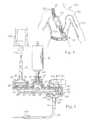
- FIG. 1is a perspective and schematic view of a first embodiment of a portable infusion pump unit according to the present invention
- FIG. 2is an elevational and partly sectional view of the first embodiment of the portable infusion pump unit illustrated in FIG. 1 ,
- FIG. 3is a schematic view of the interior of the first embodiment of the portable infusion pump unit illustrated in FIGS. 1 and 2 , disclosing the flow path thereof,
- FIG. 4is a schematic view illustrating a possible application of the first embodiment of the portable infusion pump unit illustrated in FIGS. 1, 2 and 3 ,
- FIG. 5is a perspective and schematic view illustrating the application of the first embodiment of the portable infusion pump unit illustrated in FIGS. 1-4 in a stationary charger and fixation system for providing a stationary infusion pump system,
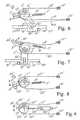
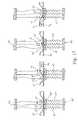
- FIGS. 6 and 7are schematic illustrations of a first embodiment of a pump actuator according to the invention in two different positions, namely with the activating pin fully retracted in FIG. 6 , and with the activating pin fully extended in FIG. 7 ,
- FIGS. 8 and 9are schematic illustrations of a second and third embodiment, respectively, of a pump actuator according to the invention.
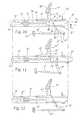
- FIGS. 10-12are schematic illustrations of three stages in the operation of a fourth embodiment of an actuator according to the invention.
- FIG. 13is a graph showing two curves of Contraction versus Force for shape memory alloy wires for different biasing systems for the actuators according to the invention.
- FIG. 14is a graph showing the relationship between various forces in Newton and the distance of displacement of a piston pump plunger in mm by the actuator shown in FIGS. 10-12 .
- FIGS. 15 and 16are schematic illustrations similar to FIG. 2 of a second embodiment of an infusion pump unit according to the invention illustrating the use of the shape memory alloy actuators of FIGS. 6-7 and FIGS. 10-12 , respectively, as the pump actuators
- FIG. 17is a sequence of schematic illustrations showing various stages in the pumping cycle of a fluid pumping system according to the invention utilizing SMA actuators,
- FIG. 18schematically illustrates two stages in the operation of an SMA actuator incorporated in the pumping system in FIG. 17 ,
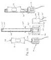
- FIG. 19is a schematic illustration of a first embodiment of a shape memory alloy actuator motor for use in an infusion pump according to the invention.
- FIG. 20is a schematic illustration of a second embodiment of a shape memory alloy actuator motor for use in an infusion pump according to the invention.
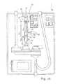
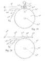
- FIG. 21is a schematic, partly sectional view of an infusion device according to the invention particularly well suited for dispensing insulin to a diabetes patient,
- FIG. 22is a schematic view of the actuator and dispensing syringe of the device in FIG. 21 .
- FIG. 23is a schematic view of a second embodiment of an actuator and a dispensing syringe for incorporation in the device in FIG. 21
- FIG. 24is a schematic view of a rack-type SMA actuator for incorporation in the device in FIG. 21 .
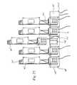
- FIG. 25is a perspective and schematic view illustrating an alternative application of the first embodiment of the portable infusion pump unit illustrated in FIGS. 1-4 in a stationary charger and fixation system for providing a stationary infusion pump system, and
- FIG. 26is a perspective and schematic view of the components of the system in FIG. 25 .
- a first embodiment of a portable infusion pump unit or apparatusdesignated the reference numeral 10 in its entirety.
- the apparatus 10comprises a housing composed of two shell-like housing parts 12 and 14 constituting a front and rear housing part, respectively.
- the front an rear housing parts 12 and 14are easily disassembled allowing the user to obtain access to the interior of the apparatus for substituting an interior fluid passage component to be described in greater detail below with reference to FIG. 3 constituting a disposable pre-sterilized component which is easily demounted after use and readily replaced prior to use.
- a clip 16From the rear side of the housing part 14 , a clip 16 allowing the apparatus 10 to be fixed to a strap or a belt extends.
- a display 20is provided, comprising two sets of two digits designated the reference numerals 22 and 24 , respectively, for displaying digits representing the time lapsed or the time remaining for infusion operation expressed in minutes and hours, respectively, or seconds and minutes, respectively, or alternatively for displaying digits representing the supply of infusion liquid as expressed in volume per time unit, e.g. ml per hour.
- the display 20further includes a display area 26 for informing the user and/or a person operating the infusion pump apparatus 10 or nursing the user regarding the operational mode of the apparatus, such as standby or running information.
- the display 20includes a number of individual displays positioned above one another and above the standby/running display 26 , one of which is designated the reference numeral 28 .
- These individual displays 28are adapted to display information such as the operational mode, e.g. the information that the apparatus is in a program mode, information regarding whatever information is presented on the two-digit displays 22 , 24 , such as the time remaining for infusion operation, the total time of the infusion operation, whether or not the apparatus is running or is to be started, or any other relevant information to be presented to the user or operator.
- the display 20further includes three individual alarm displays 30 , 32 and 34 for informing the user of the presence of air in the infusion pump circuitry, pressure fault or failure or low battery, respectively.
- a further display 36informs the user or operator of the program sequence presently used or programmed, which program sequence is represented by a digit displaced by a 1-digit display 38 .
- a 3-digit display 40 of the display 20represents information to the user or operator regarding the infusion supply measured in ml per hour or similar relevant measure or ratio.
- a keyboard 42including a set of keys, one of which is designated the reference numeral 44 for allowing the user/operator to control the portable infusion pump unit 10 to perform a specific operation or to program the apparatus by shifting between specific program sequences by increasing a specific digit displayed in a 1-, 2- or 3-digit display, such as the displays 22 , 24 , 38 and 40 , by increasing or reducing the digit in question and by shifting a cursor route relative to the various individual displays of the display 20 for allowing the user/operator to modify the operational mode or shift between various preset programs of the apparatus.
- two terminals 46 and 48are provided for allowing the apparatus 10 to be connected to an electronic charger for supplying electric power to an internal rechargeable battery pack or cell of the apparatus.
- the terminals 46 and 48may alternatively or additionally serve as input/output terminals for establishing communication between the apparatus 10 and an external apparatus or equipment such as an external data logging apparatus or surveillance apparatus or further alternatively for communicating with an external processing unit such as a personal computer or data logging apparatus.
- the apparatus 10may be provided with a conventional input/output terminal such as a conventional RS 232 terminal for establishing communication between the apparatus 10 and an external computer such as the above-mentioned personal computer for processing data produced by the apparatus concerning the operational mode of the apparatus and also supplementary data produced by the apparatus or auxiliary equipment, e.g. data representing the temperature of the infusion liquid supplied by the apparatus 10 or data supplied by additional external measuring or surveillance equipment.
- a conventional input/output terminalsuch as a conventional RS 232 terminal for establishing communication between the apparatus 10 and an external computer such as the above-mentioned personal computer for processing data produced by the apparatus concerning the operational mode of the apparatus and also supplementary data produced by the apparatus or auxiliary equipment, e.g. data representing the temperature of the infusion liquid supplied by the apparatus 10 or data supplied by additional external measuring or surveillance equipment.
- an external computersuch as the above-mentioned personal computer for processing data produced by the apparatus concerning the operational mode of the apparatus and also supplementary data produced by the apparatus or auxiliary equipment, e.
- FIG. 2the interior structure of the portable infusion pump unit or apparatus 10 is disclosed, illustrating the fluid inlet 50 and the fluid outlets 52 and 54 .
- the reference numerals 56 and 58designate two printed circuit boards including the electronic circuitry of the apparatus and including the display, the rechargeable power pack or cell circuitry and the CPU-circuitry of the apparatus controlling the overall operation of the apparatus including the infusion operation.
- the electronic circuitry of the apparatusmay be included in a single printed circuit board or, alternatively, three or more printed circuit boards.
- the internal re-chargeable battery pack or cellis designated the reference numeral 60 .
- the internal flow system of the portable infusion pump apparatus 10constituting a disposable and replaceable fluid passage component as mentioned above and including an inlet tube 62 connected to the fluid inlet 50 .
- Two capacitive detectors 64 and 66are mounted on the inlet tube 62 and communicate with the electronic circuitry of the apparatus housed on the printed circuit board 56 and 58 for detecting presence of air bubbles, if any, in the infusion liquid input to the fluid inlet 50 .
- the inlet tube 62communicates with a first check valve 68 which constitutes an inlet to a pump housing component 70 , in which an internal fluid passage is provided, as will be described in greater details below with reference to FIG.
- a piston type pump actuator 78is provided for transferring the infusion liquid or any other liquid input to the portable infusion pump unit 10 through the fluid inlet 50 to an application site through one of the fluid outlets 52 and 54 .
- the internal flow system of the portable infusion pumpcomprising the fluid inlet 50 , the inlet tube 52 , the capacitive detectors 64 and 66 belonging to the inlet tube 62 , the first check valve 68 , the pump housing component 70 , the output check valve 72 , the outlet tubes 74 and 76 , and the outlets 52 and 54 constitute an integral disposable and replaceable fluid passage component to be described in greater detail below with reference to FIG. 3 .
- the first check valve 58basically comprises a central circular cylindrical housing component 80 from which a frusto-conical top part 81 extends upwardly communicating with the inlet tube 62 and arresting an inlet filter element 82 at the transition between the frusto-conical top part 81 and the cylindrical housing component 80 .
- the cylindrical housing component 80comprises a central annular oral component 84 which is sealed off in the initial or non-active position by a downwardly deflectable sealing membrane 86 .
- the membrane 86is forced downwardly allowing liquid to pass through the central aperture of the central annular component 84 and further through apertures 87 provided offset relatively to the centre of the sealing membrane 86 .
- the first check valve 68communicates with an inlet passage 88 of the pumping house component 70 terminating in an inner chamber defined within an upwardly protruding annular top housing component 90 in which a reciprocating plunger 94 of the piston pump actuator 78 is movable in the direction to and from an abutting pin 96 which separates the inlet passage 88 from an outlet passage 98 .
- the interspace between the reciprocating plunger of the piston pump 78 and the inner surface of the annular top housing component 90is sealed by means of a highly flexible sealing gasket 92 .
- the outlet passage 98communicates with the above described second check valve 72 which is basically of a configuration similar to and functioning as a check valve similar to the above described first check valve 58 , however differing from the above described first check valve in that the second check valve 72 does not include any filter element similar to the filter element 82 .
- the second check valve 72includes a downwardly protruding annular housing part 100 , which is cast integral with the pumping house component 70 , fulfilling, however, the same purpose as the above described annular housing part 80 of the first check valve.
- a downwardly protruding frusto-conical housing part 101 similar to the above described frusto-conical housing part 81extends communicating with the outlet tube 74 and similarly the outlet tube 76 described above with reference to FIG. 2 .
- a sealing membrane 102 similar to the above described sealing member 86is received, which includes apertures 103 similar to the apertures 87 described above.
- the sealing membrane 102communicates with a conical bore 99 communicating with the outlet passage 98 for sealing off communication from the outlet passage 98 , through the conical bore 99 to the outlet tube 74 provided the sealing membrane 102 rests against an abutting lower surface defining the lower boundary of the conical bore 99 .
- the pumping operation of the portable infusion pump unit 10is established as follows. Initially, the first check valve 68 and the second check valve 72 are in their initial and sealing positions. It is also assumed that liquid is present within the inlet tube 62 within the inlet passage 88 and the outlet passage 98 and also within the outlet tube 74 .
- the piston pump actuator 78is activated through the supply of an electric signal such as an alternating electric signal or a pulsed signal causing the reciprocating plunger 94 to move upwardly or downwardly.
- the piston pump actuator 78will be described in greater detail below with reference to FIGS. 6-12 .
- the plunger 94is pressed downwardly in relation to the orientation of the piston pump actuator 78 shown in FIG. 3 .
- the relative vacuum within the outlet passage 98creates a relative vacuum above the sealing membrane 102 which is biased so as to prevent free flow through the second check valve 72 urging or forcing the sealing membrane into sealing off and abutting engagement with a wall part circumferentially encircling and defining the conical bore 99 , and consequently preventing liquid from being transferred from the outlet passage 98 to the outlet tube 74 .
- the first check valve 68is activated and caused to open whereas the second check valve 72 is blocked.
- the rate of transfer and consequence the flow of liquid from the outlet tube 74is controlled by the rate of operation of the piston pump actuator 78 as an increased frequency of reciprocating the reciprocating plunger 94 increases the velocity of flow of fluid or liquid from the inlet tube 62 to the outlet tube 74 .
- a bypass valvecomprising a sealing membrane 104 which is acted upon by a central stem element 106 of a turnable knob 108 so as to force the sealing membrane 104 into sealing off and abutting engagement with a conical bore 105 provided above and in registration with the above described conical bore 99 .
- the bypass valveis not in operation.
- the sealing membrane 104is raised from its sealing off and abutting engagement with the conical bore 105 as the knob 108 is rotated for causing elevation of the actuator stem 106 , communication from the outlet passage 98 is established through a bypass passage 110 , bypassing the communication from the outlet passage 98 through the conical passage 99 for allowing fluid to flow from the outlet passage 98 through the bypass passage 110 and further through the apertures 103 of the sealing membrane 102 which is consequently not functioning as the bypass valve is in operation.
- the piston pump actuator 78which may constitute a replaceable component of the portable infusion pump unit or apparatus 10 , may provide a specific stroke and, consequently, a specific flow volume per stroke. Therefore, the actuator 78 is preferably provided with a switch cooperating with a switch of the electronic circuitry of the apparatus for informing the microprocessor of the electronic circuitry of the apparatus of the type of piston pump actuator included within the apparatus at present.
- the technique of providing information to the microprocessor concerning the type of piston pump included within the apparatus at presentmay be established by means of numerous techniques well-known in the art per se such as by means of code switches, optic capacitive or inductive readers, or simply by means of a feedback circuit monitoring the work rate of the piston pump actuator.
- an inlet tube 112is shown establishing communication from the inlet tube 62 through the fluid inlet 50 not shown in FIG. 3 , however, shown in FIG. 2 from an infusion bag 114 which may constitute an infusion bag including an infusion liquid simply constituting physiological liquid or additionally or alternatively a drug suspended in any appropriate liquid, or alternatively blood plasma.
- the outlet from the outlet tube 74 of the portable infusion pump unit 10 shown in FIG. 4is connected to an outlet tube 116 through the fluid outlet 54 , not shown in FIG. 3 , however, shown in FIG. 2 , which external outlet tube 116 communicates with a cannular assembly 118 of a basically conventional structure.
- the inlet tube 112 and the outlet tube 116may constitute separate inlet and outlet tubes to be connected to the infusion pump unit 10 through the inlet and outlet 50 and 52 or, alternatively, 54 , respectively.
- the inlet tube 112 and the outlet tube 116constitute integral components of the disposable and replaceable fluid passage component illustrated in FIG. 3 , which fluid passage component is cooperating with and activated by means of the piston pump actuator 78 .
- the infusion bag 114may be configurated and housed within a container component which is configurated so as to allow the infusion bag 114 to be received and supported on top of the infusion pump unit or apparatus 10 as the above-mentioned receiver is simply connected to and supported by the housing of the portable infusion unit or apparatus 10 .
- FIG. 4The infusion of liquid from the infusion bag 104 is further illustrated in FIG. 4 , in which the portable infusion pump 10 is received and fixed relative to an individual 120 by means of a belt or strap 122 on which the infusion bag 114 is further fixated.
- the external inlet tube 112 , the external outlet tube 116 and the cannular assembly 118are also illustrated.
- FIG. 5the above described first embodiment of the portable infusion pump unit or apparatus 10 is shown in duplicate received within a stationary receptor 140 in which a plurality of receptor compartments 142 are defined.
- Each of the receptor compartments 142is provided with a set of charger terminals for establishing electrical conductive communication with the charger terminal 46 and 48 of the apparatus or unit 10 received within the receptor compartment 140 in question for charging the internal rechargeable battery pack or cell of the apparatus or unit through the supply of electric energy from a mains power supply unit of the receptor assembly 140 which mains supply power supply unit receives electric power through a coiled mains supply wire 148 terminating in a mains plug 150 which is received in a mains AC outlet socket 152 .
- the receptor assembly 140further includes a set of indicator lamps 144 and 146 . Provided none of the indicator lamps 144 and 146 corresponding to a specific receptor compartment 142 are turned off, the indication informs the user or operator that no charging is taking place in the receptor compartment in question. Provided a portable infusion pump unit is received within a specific receptor compartment 142 , one of the lamps 144 and 146 corresponding to the receptor compartment is turned off, one of which informs the user or operator that the potable infusion pump unit in question is to be recharged, or alternatively the other lamp is turned on informing the user or operator that the portable infusion pump unit in question is fully charged and ready for use. Alternative information display modes, such as flashing of lamps for informing malfunction in the rechargeable battery pack or cell of the portable infusion pump is of course also readily deduceable.
- the pump actuator 78 in FIGS. 2 and 3is, according to the invention, a shape memory alloy actuator which embodies all the above desirable characteristics.
- shape memory alloy actuators for use as a pump actuator in medicinal infusion pumpswill be described in following, it being understood that these actuators are particularly useful as the pump actuator 78 in FIGS. 2 and 3 .
- a pivotable body in the form of a circular disc 1 ′is arranged for pivoting around a central pivot 2 ′ fixedly attached to a not shown frame of the actuator, and the disc 1 ′ is provided with a peripheral extension 3 ′ and a yoke-like peripheral extension 5 ′.
- a tension coil spring 6 ′is at one end thereof pivotably attached to a fastening pin 7 ′ fixedly attached to said frame and is at the other end thereof pivotably attached to a fastening pin 8 ′ fixedly attached to the peripheral extension 3 ′.
- a shape memory alloysuch as nickel titanium alloy or nitinol
- each of the wires 9 ′ and 10is attached to an electrically conductive terminal 13 ′ fixedly attached to the periphery of the disc 1 ′.
- the wires 9 ′ and 10 ′extend along the periphery of the disc 1 ′ such that the wires 9 ′ and 10 ′ when tensioned extend along and are supported by said periphery.
- the wires 9 ′ and 10 ′are shown spaced from said periphery for the sake of clarity.
- a sliding body 14 ′ having two arms 15 ′ and 16 ′is arranged for sliding movement between two stop pins 17 ′ and 18 ′ attached to the frame.
- a pin 19 ′ attached to the sliding body 14 ′is received in the fork 5 a ′ of the yoke-like extension 5 ′ such that the pin 19 ′ may slide and rotate freely in the fork when the disc 1 ′ pivots from the position shown in FIG. 6 to the position shown in FIG. 7 thereby slidingly displacing the body 14 ′ from abutment against stop pin 18 ′ to abutment against stop pin 17 ′ with the arm 15 ′, constituting the activating pin of the actuator, fully extended.
- a proximity sensor 20 ′is attached to the frame and connected to not shown electrical conductors for transmitting a signal from the sensor to a not shown receiver.
- the terminals 11 ′ and 12 ′are likewise each connected to an electrical conductor, not shown, connected to a not shown power source for supplying electrical power to the wires 9 ′ and 10 ′ for resistance heating thereof, the terminal 13 ′ being likewise connected to the not shown power source through a not shown electrical conductor for closing the resistance heating circuit.
- the wires 9 ′ and 10 ′are intermittently heated to the transformation or transition temperature (from martensitic to austenitic state) of the shape memory alloy which temperature for nitinol is approximately 90° C. Thereby the length of the wire is shortened. When the wire cools to below 90° C. the length thereof reverts to normal, i.e. the wire lengthens. The speed at which the shortening takes place, i.e. the contraction time, is directly related to the current input. i.e. the voltage applied over the terminals 11 ′ or 12 ′ and 13 ′.
- the intermediate disc 1 ′In the position depicted in FIG. 6 , the intermediate disc 1 ′ is in its outermost counter clock-wise position with the arm 15 ′ fully retracted and with the wire 9 ′ cooled to below 90° C. and the wire 10 ′ heated to above 90° C. by applying an electrical voltage between the terminal 12 ′ and 13 ′ whereby an electrical current will flow through the wire 10 ′.
- the disc 1 ′has therefore been rotated counter clock-wise to the position shown by the contraction force exerted by the wire 10 ′.
- the wire 10 ′is cooled to below 90° C. and thereby lengthens to the shape indicated by the dotted line 10 a ′ in FIG. 6 .
- the actuatoris now ready to perform an activating extension of the arm 15 ′ towards the left, the end of the arm 15 ′ being intended to come into contact with a not shown plunger 94 and depress or activate same during the movement of the arm 15 ′ to the extended leftwards position thereof as depicted in FIG. 7 .
- the wire 9 ′is heated to above 90° C. whereby it contracts and exerts a clock-wise force on the disc 1 ′ pivoting it clock-wise around the pivot 2 ′ past the balance position of the disc 1 ′ and spring 6 ′ in which the attachment pins 7 ′ and 8 ′ of the spring 6 ′ are aligned with the pivot 2 ′.
- An increase of the activating force of the actuator during the activating strokeis also achieved or enhanced by decreasing the distance of the pin 19 ′ from the pivot 2 ′ or axis of rotation of the disc 1 ′ during the activating stroke whereby the moment arm or lever of force of the displacement force exerted on the pin 19 ′ by the yoke-like extension 5 ′ with respect to the pivot 2 ′ is decreased and thereby the displacement force is increased during the activating stroke.
- This shortening of said distancecan be seen from the situation in FIG. 6 at the beginning of the activation stroke to the situation in FIG. 7 at the end of the activation stroke.
- the wire 10 ′is heated above 90° C. so that it contracts and pivots the disc 1 ′ back to the position shown in FIG. 6 whereby the activating cycle is ready to be repeated.
- the length of the wire 10 ′is larger than the length of the wire 9 ′ because the contraction or shortening of the wire 10 ′ must be large enough to pivot the disc 1 ′ from the position shown in FIG. 7 past the balance point mentioned above while the shortening of the wire 9 ′ only has to be enough the pivot the disc 1 ′ from the position shown in FIG. 6 past said balance point.
- Nitinol wireswill typically contract about 3%-6% when heated past the transition temperature.
- the uncontracted length of the wire 10 ′should be enough to ensure that the uncontracted wire is fully extended in the position shown in FIG. 7 and that the contracted wire 10 ′ is fully extended when the disc 1 ′ is at least slightly past said balance point in the counter-clockwise direction, i.e. the uncontracted length of wire 10 ′ should be about 22-25 times the distance of travel of terminal 13 ′ between the FIG. 7 position thereof and the balance point position thereof.
- the necessary contraction force to be exerted by wires 9 ′ and 10 ′are rather different because the contraction force of wire 9 ′ only has to counteract the torque or moment of the spring force of spring 6 ′ with the relatively small torque arm in FIG. 6 while the contraction force of wire 10 ′ has to counteract the considerably larger torque of said spring force in FIG. 7 .
- the contraction force of a nitinol wireis larger the larger the diameter or cross sectional area of the wire.
- the cross sectional area of wire 10 ′is thus considerably larger than the cross sectional area of wire 9 ′ or there may be a number of wires 10 ′ with the same cross sectional area.
- the cooling-off time for the wires 10 ′is as short of possible so that the interval between the activating cycles may be as short as possible.
- Several small diameter wires with a certain total cross sectional areawill cool more rapidly than a single larger diameter wire with the same cross sectional area.
- the signal emitted by the proximity sensor 20 ′ each time the extension 3 ′ is in the position shown in FIG. 7may be utilized for many different purposes such as for instance a mere monitoring of the correct function of the actuator or for controlling the timing of the heating of the wires 9 ′ and 10 ′ and thereby the timing of the activating stroke of the sliding body 14 ′.
- the location of the proximity sensor or of any other type of sensor for sensing the position of the disc 1 ′may be varied according to the purpose thereof, and several such sensors may be provided in different locations for instance for achieving a more complex control of the timing of the activating effect of the actuator.
- this embodimentdiffers from the embodiment of FIGS. 6-7 in that a double activating effect may be achieved for each cycle of heating and cooling the shape memory wires 21 ′ and 22 ′ that in this case are of equal length and cross sectional area.
- the rotation of the disc 1 ′ counter-clockwise and clockwiseis limited by stop pins 23 ′ and 24 ′, respectively.
- the activating membermay be a sliding body similar to body 14 ′ in FIG. 6-7 where both the arm 15 ′ and the arm 16 ′ perform an activating function, or the activating function may be a pull/push activation by for instance arm 15 ′.
- the disc 1 ′may alternatively be provided with a central torsion shaft projecting at right angles to the plane of the disc 1 ′ as a prolongation of the pivot 2 ′ such that the torsion shaft functions as the activating member by for instance rotating a lever to and fro.
- the disc 1 ′has just performed an activating rotation counter-clockwise under the influence of the counter-clockwise torque of the force of the spring 6 ′ and is ready for the initiation of a rotation clockwise by heating the wire 21 ′ so that the disc 1 ′ is rotated against the counter-clockwise torque of the spring force until the balance point is passed. Then the activating rotation clock-wise is performed by the clock-wise torque of the spring force. Also in this embodiment the moment arm of the activating force of the spring 6 ′ increases during the activating stroke in both directions.
- the terminal 13 ′ of the embodiments of FIGS. 6-8has been substituted by a combined terminal and abutment member 28 ′ for abutting the stop pins 24 ′ and 25 ′.
- a piston and cylinder mechanismcomprising a pressurized cylinder 24 ′ pivotably attached to pin 7 ′, a piston 26 ′ and a piston rod 27 ′ pivotably attached to the disc 1 ′ by means of a pin 27 ′.
- the piston and cylinder mechanism 24 ′- 25 ′functions like a compression spring and could in fact be substituted by a compression spring.
- the disc 1 ′is in the balance point position where the pin 7 ′, the pin 27 ′ and the pivot 2 ′ are aligned such that the pressure exerted on the disc 1 ′ by the piston rod 25 ′ does not produce any torque on the disc 1 ′.
- the wire 22 ′is contracting and rotating the disc counter clock-wise past the balance point.
- the tension spring 6 ′ in FIGS. 6-7could also be substituted by a piston and cylinder mechanism or a compression spring in an arrangement similar to FIG. 9 .
- an activating body 30 ′is arranged linearly displaceable in the directions of arrows R 1 and R 2 under the influence of a shape memory alloy wire 31 ′ and a two-armed lever 32 ′.
- One end of the wire 31 ′is attached to the body 30 ′ at 33 ′ and the other end is attached to a fixed portion 37 a ′ of a not shown frame of the actuator, the wire 31 ′ extending around a pulley 34 ′ pivotably arranged on a slide 35 ′ displaceable in the directions of the arrows R 1 and R 2 .
- a compression spring 36 ′is arranged between the body 30 ′ and the slide 35 ′ and extends through a passage through a fixed portion 37 ′ of said frame.
- the two-armed lever 32 ′is arranged pivotable around a pivot 38 ′, one arm 39 ′ of the lever abutting a pin 40 ′ on the body 30 ′ and the other arm 41 ′ of the lever being attached at 42 ′ to one end of a tension spring 43 ′, the other end being attached to a fixed portion 44 ′ of said frame such that displacement of the body 30 ′ in the direction of arrow R 1 tensions the spring 43 ′ via rotation of the intermediate lever 32 ′.
- a pawl or hook element 45 ′is arranged pivotable around a pivot 46 ′ such that a hook or projection 47 ′ of the hook element 45 ′ may be received in a matching recess 48 ′ in the body 30 ′.
- a shape memory alloy wire 49 ′is at one end attached to the hook element 45 ′ and at the other end attached to a fixed portion 50 ′ of said frame.
- a compression spring 51 ′is arranged between the fixed portion 50 ′ and the hook element 45 ′
- the body 30 ′is moved to and fro in the direction of the arrows R 1 and R 2 to activate the plunger 94 during the activating stroke of the body in the direction R 1 .
- the wire 31 ′is cooled to below the transformation temperature of the alloy (for instance by sandwiching the wire between two aluminum rails coated with PTFE) and is at its maximum length and is maintained taut by the biasing action of the compression spring 36 ′.
- the hook 47 ′is received in the recess 48 ′ and holds the body 30 ′ against the biasing force of the spring 43 ′ transmitted to the pin 40 ′ by means of the lever 32 ′.
- the wire 49 ′is also in its cool state and at its maximum length.
- the wire 49 ′When the activating stroke is to be initiated, the wire 49 ′ is heated to the transformation temperature and shortens or contracts, thereby pivoting the hook element 45 ′ against the biasing force of the spring 51 ′ such that the hook 47 ′ is pulled out of the recess 48 ′ to the release position shown in FIG. 11 .
- the body 30 ′is thus released for displacement in direction R 1 under the influence of the lever 32 ′ pivoted by the spring 43 ′.
- the activating stroke in direction R 1will be stopped as shown in FIG. 11 .
- the activating strokepreferably is stopped by the resistance to the activating stroke of the body 30 ′ by the plunger 94 being activated such that the stroke is stopped before the slide 35 ′ abuts the fixed frame portion 37 ′.
- the wire 49 ′is cooled to allow the spring 51 ′ to pivot the hook element 45 ′ towards the holding position thereof while the wire 31 ′ is heated until it shortens and thereby causes the slide 35 ′ to abut the fixed frame portion 37 ′ and the pulley 34 ′ to rotate clock-wise while the body 30 ′ is displaced in the direction R 2 against the force of the spring 43 ′ that thereby is lengthened while the lever 32 ′ pivots counter clock-wise.
- the hook 47 ′is pressed into the recess 48 ′ and the wire 31 ′ may then be cooled so that the situation in FIG. 10 is re-established ready to initiate a new activation cycle of the actuator.
- any blocking of the activating stroke of the activating bodyfor instance because the pump plunger 94 is blocked, will only entail that the activation stroke is stopped with no damage to the SMA wire. If the activating stroke were carried out under the influence of a shortening of a shape memory alloy wire, said wire would probably be damaged or snapped if the activating stroke were blocked.
- the extra length of the wire 31 ′ obtained by means of the pulley 34 ′is advantageous for giving a longer activating stroke with a compact construction of the actuator.
- the heating of the wires 31 ′ and 49 ′is carried out in a manner similar to the heating of the wires 9 ′ and 10 ′ in FIGS. 6-7 by means of not shown electrically conductive connections of the ends thereof to the battery pack 60 of the infusion pump unit according to the invention.
- the curve or line 80 ′indicates the relationship between the force exerted by an SMA wire on a body in one direction while the body id biased by a tension spring in the opposite direction as a function of the contraction or shortening thereof.
- the forceincreases proportionally with the contraction because of the proportional increase of the spring force of the spring when it is stretched by contraction of the wire.
- the line or curve 81is symbolic of the curves corresponding to the relationship between contraction and force exerted for the embodiments of FIGS. 6-9 where the force in the wires 10 ′, 22 ′, 24 ′ and 31 ′, respectively is largest at the beginning of the contraction or shortening, and the contraction length of the wire is much larger because of the variation in the length of the moment arm or arms during the activating stroke as described above.
- the actual curves 81will not be linear but will reflect the varying rate of change of the moment arm or moment arms during the activating stroke.
- an actuator as shown in FIGS. 10-12is applied to depress the plunger 94 of the infusion pump in FIG. 3 thereof with the body 30 ′.
- the plunger 94 and body 30 ′travel from 0.2 mm to 3.4 mm during the activating stroke of the body 30 ′.
- the force required to displace the plungerincreases substantially proportionally from approx. 0.5 N to approx. 2N where the force increases steeply because the plunger has reached the end of its path.
- the infusion pump unit 10is very similar to the infusion pump unit 10 of FIG. 2 , the sole difference being the location of the print cards 56 and 58 .
- the actuators of FIGS. 6-7 and 10-12are utilized as the pump actuator 78 in FIG. 15 and FIG. 16 , respectively.
- the SMA wiresare supplied with electrical current for heating by the battery pack 60
- the SMA actuators of FIGS. 6-7 and 10-12are particularly well-suited for depressing the pump membrane 92 (see FIG. 3 ) as the force needed for this operation increases as the membrane is depressed and the fluid is pressed out into the conduit 98 . Furthermore, the operation of the SMA actuators is very quiet and the energy consumption is low while the space requirements are limited and the weight low.
- the SMA wire 31 ′ of the SMA pump actuator of FIG. 16is supplied with 4 amperes during 4 milliseconds for each pump depression cycle, and the maximum number of depression cycles for the infusion pump is normally of the order of magnitude of 10,000 cycles/hour.
- a fluid pumping system 60 ′comprises a flexible tube 61 ′ extending through or between at least three clamping devices 62 ′- 64 ′ arranged adjacent one another.
- the clamping deviceseach comprise a pivotable jaw 65 ′ that is arranged to pivot towards a fixed jaw 66 ′ to flatten the tube 61 ′ extending between the jaws 65 ′ and 66 ′ and to pivot away from the fixed jaw 66 ′ to allow the tube 61 to return to its natural open shape.
- Each of the pivotable jaws 65 ′is attached to one end of a biasing means such as a tension spring 67 ′ the other end of which is attached to a fixed portion 68 ′ of a not shown frame.
- Each of the pivotable jaws 65 ′is furthermore attached to one end of a shape memory alloy wire 69 ′ the other end of which is attached to a fixed portion 70 ′ of said frame.
- the jaws 65 ′are held in the closed position against jaw 66 ′ by the springs 67 ′ with the tube 61 ′ flattened while shortening or contraction of the SMA wires 69 ′ opens the clamping devices by pivoting the jaws 65 ′ away from the fixed jaw 66 ′.
- the pumping actionis achieved by the sequence indicated from left to right in FIG. 17 , all three clamping devices 62 ′- 64 ′ being clamped shut in the first stage from the left with all three wires 69 ′ cooled to below the transition temperature and therefore slack.
- the device 61 ′opens while the device 62 ′ closes whereby the portion of fluid trapped in the space 71 ′ is forced to flow in the direction of arrow R 6 whereafter device 61 ′ is closed and the first stage from the left has been re-established to begin a new pumping cycle.
- This “finger” pumpmay substitute the pumping system in FIGS. 3, 15 and 16 as well as the check valves 68 and 72 , and the pumping system (tube 61 ′) may still be replaced without replacing the pump actuator by threading the tube 61 ′ from between the jaws 65 ′ and 66 ′. Thereby an extremely cheap replaceable pump is provided.
- each of the jaws 65 ′ of the clamping devices 62 ′- 64 ′ towards the fixed jaw 66 ′may be achieved by means of a body 15 ′ of the actuator in FIG. 6 or a body 30 ′ of the actuator in FIG. 5 .
- the tube 61 ′may alternatively be flattened directly by said bodies 15 ′ or 30 ′ without the use of a clamping device.
- a particularly simple pumping systemis achieved where the replacement of the tube 61 ′ is particularly simple.
- a toothed wheel or gear 55 ′′is rotatably arranged on a power output shaft 56 ′′ journalled in a not shown frame of the actuator motor.
- a body 57 ′′ having an edge portion 58 ′′ fitting between two neighbouring teeth 59 ′′ of the gear 55 ′′is arranged in said frame displaceable between the position shown in full lines and the position shown in dotted lines.
- a shape memory alloy wire 60 ′′is at one end attached to the body 57 ′′ and at the other end to a fixed portion 61 ′′ of said frame.
- a coiled flat or wire spring 62 ′′ integral with or connected to an arm 63 ′′is attached to said frame such that said arm 63 ′′ may pivot around one end thereof opposite the free end thereof.
- the arm 63 ′′abuts a pin 64 ′′ on the body 57 ′′.
- a pawl 65 ′′is pivotably arranged on a pivot 66 ′′ and is biased by a tension spring 67 ′′ so as to constantly abut the rim of the gear 55 ′′.
- the gear 55 ′′is turned clock-wise by the body 57 ′′ being displaced from the full line position to the dotted line position thereof by the force of the spring 62 ′′ acting through the intermediate arm 63 ′′ on the pin 64 ′′, whereby the gear advances the width of one tooth 59 ′′ and the pawl 65 ′′ moves from locking engagement between one pair of teeth 59 ′′ to a locking position between the next pair of teeth in the counter clock-wise direction.
- the lever or moment arm of the displacement force exerted by the intermediate arm in the clock-wise direction with respect to the pivoting point of the armdecreases as the body is displaced in the activating direction from the full line position to the dotted line position whereby the displacement force exerted by the intermediate arm 63 ′′ on the pin 64 ′′ increases.
- FIG. 20a SMA actuator motor similar to the motor of FIG. 19 is shown, the spring 62 ′′ and intermediate arm 63 ′′ being substituted by a tension spring 68 ′′ fastened to the body 57 ′′ and to a fixed portion 69 ′′ of a not shown frame.
- the operation of the motor of FIG. 20is very similar to the one in FIG. 19 except that the displacement force exerted on the body 57 ′′ by the spring 68 ′′ is exerted directly and declines substantially proportionally with the distance of displacement.
- an infusion pump 70 ′′ particularly well suited for infusing insulin to a diabetes patientcomprises a housing 71 ′′ containing a display 72 ′′, on/off buttons 73 ′′, print cards 74 ′′ and a not shown battery pack.
- a dispensing cartridge, ampoule or syringe 75 ′′is replaceably arranged in the housing 71 ′′ and has an outlet nozzle 76 ′′ for communication with a not shown conduit means connected to the patient for delivering the fluid, preferably insulin, in the syringe 75 ′′ to said patient in a controlled manner either continuously or according to a predetermined sequence.
- a piston 77 ′′is slideably arranged in the syringe 75 ′′.
- a threaded rod or spindle 78 ′′abuts the piston 77 ′′ for displacing it towards the outlet nozzle 76 ′′ and meshes with a gear 79 ′′ meshing with a pinion 80 ′′ rotated by a shape memory alloy motor for displacing the spindle 78 ′′ towards the outlet nozzle 76 ′′.
- the SMA motor of FIG. 20is shown arranged and adapted for rotating the pinion 80 ′′ such that rotation of the gear 55 ′′ is geared down to a much slower rotation of the spindle 78 ′′ so as to dispense the liquid or paste in the syringe 75 ′′ in very small amounts.
- the SMA motor of FIG. 19may very advantageously replace the motor of FIG. 19 in the configuration of FIG. 22 because of the reverse characteristic of the spring 62 ′′ compared to the characteristic of spring 68 ′′ as discussed in connection with FIGS. 13 and 14 .
- a double headed piston 81 ′′being displaced by an arm 82 ′′ mounted on a carrier block 83 ′′ rotatably mounted on a spindle 84 ′′ such that rotation of the spindle 83 ′′ displaces the block 83 ′′, arm 82 ′′ and piston 81 ′′ towards the nozzle 76 ′′ for expelling liquid or paste in the syringe 75 ′′.
- the spindlemeshes with a gear 85 ′′ meshing with a pinion 86 ′′ attached to the shaft 56 ′′ of the SMA motor of FIG. 19 , the spring 67 ′′ not being shown for the sake of clarity.
- a rack 70 ′′′is arranged displaceable in a not shown frame in the direction R 4 and a body 71 ′′′ is arranged displaceable in the directions R 3 and R 4 as well as transversely thereto.
- a SMA wire 72 ′′′is attached to the body 71 ′′′ and to a fixed portion 73 ′′′ of said frame.
- a coil spring 74 ′′′ attached to said frame and integral with or connected to an intermediate arm 75 ′′′exerts a displacement force on a pin 76 ′′′ of the body 71 ′′′ through the intermediate arm 75 ′′′ in a manner very similar to spring 62 ′′ in FIG. 19 .
- the rack 70 ′′′advances the distance of the width of one tooth 78 ′′′ thereof in the direction R 4 for every cycle of heating and cooling of the SMA wire 72 ′′′ in the same way as gear 55 ′′ in FIG. 19 is rotated by wire 60 ′′, spring 62 ′′, intermediate arm 63 ′′ and body 57 ′′ in FIG. 19 .
- the rack 70 ′′may be used to push the piston 77 ′′ in FIG. 22 or piston 81 ′′ in FIG. 23 by means of front end 77 ′′′, to empty said cylinder of liquid or paste through an aperture in said cylinder.
- an optional number of infusion pump units 10 with corresponding inlet tube 112 and infusion bag 114may be aggregated in a system of individual docking stations 100 ′ arranged on a not shown standard hospital rack allowing horizontally adjustable location of the docking stations 100 ′ that such two or more stations may be aligned abutting one another as shown in FIG. 25 .
- a power distribution and computer connection box 101 ′ having connections 102 ′ to a power source and a computeris also adapted for abutting a docking station 100 ′ in aligned configuration therewith.
- the distribution box 101 ′has a number of female contact plugs 103 ′ for mating with corresponding, not shown, male contact plugs in a lateral wall of a docking station 100 ′.
- a diode 101 a ′indicates whether the distribution box is functioning or not.
- Each docking stationhas a number of female contact plugs 104 ′ in the opposite lateral wall identical to contact plugs 103 ′ for mating with said not shown male contact plugs of an adjacent docking station 100 ′.
- the female and male contact plugsdistribute electrical energy to the individual docking station and to the individual infusion pumps 10 docked in the docking stations 100 ′ via female contact plugs 105 ′ mating with not shown corresponding male contact plugs in the bottom of each infusion pump 10 .
- Each infusion pump 10is carried by a carrying frame 106 ′ between arms 107 ′ thereof and supported on a bottom platform 108 ′ thereof.
- a hook 109 ′is provided on the carrying frame 106 ′ for hooking into an aperture 110 ′ of the infusion bag 114 .
- the frame 106furthermore has a top aperture 111 ′ for receiving a hook on a bed or wheel chair when the pump 10 and bag 114 are to be removed from the docking station 100 ′ for following a patient away from the fixed docking station array.
- Each docking station 100 ′is provided with three diodes 112 ′ for indicating status of the docking station and the pump as regards power supply, pumping status and fluid supply or other parameters desired monitored.
- Each docking stationfurthermore has two opposed grooves for slidingly receiving the lateral edges of a frame 106 ′
- the system of FIG. 25affords great flexibility as to number of infusion pumps per patient and as regards mode of transport together with the patient either on the frame 106 ′ or removed therefrom.
Landscapes
- Health & Medical Sciences (AREA)
- Vascular Medicine (AREA)
- Engineering & Computer Science (AREA)
- Anesthesiology (AREA)
- Biomedical Technology (AREA)
- Heart & Thoracic Surgery (AREA)
- Hematology (AREA)
- Life Sciences & Earth Sciences (AREA)
- Animal Behavior & Ethology (AREA)
- General Health & Medical Sciences (AREA)
- Public Health (AREA)
- Veterinary Medicine (AREA)
- Infusion, Injection, And Reservoir Apparatuses (AREA)
- Details Of Reciprocating Pumps (AREA)
- Reciprocating Pumps (AREA)
Abstract
Description
- a body arranged displaceable between a first and a second position,
- releasable holding means adapted for holding said body in said first position,
- at least one first and at least one second wire made of a shape memory alloy such as nitinol, said first wire being at one end connected to said body such that shortening of the length of said first wire exerts a force on said body for moving said body from said second to said first position, and
- a biasing means, such as a tension spring, a compression spring, a straight or arcuate flat spring or a piston and cylinder mechanism, arranged and adapted for biasing said body for moving said body from said first to said second position,
- said second wire having one end connected to said holding means such that shortening of the length of said second wire releases said holding means for allowing said biasing means to move said body from said first position to said second position.
- a body arranged displaceable between a first and a second position,
- at least one first wire made of a shape memory alloy such as nitinol, said first wire being at one end connected to said body such that shortening of the length of said first wire exerts a force on said body for moving said body from said second to said first position,
- a biasing means, such as a tension spring, a compression spring, a straight or arcuate flat spring or a piston and cylinder mechanism, and
- a rotatably arranged intermediate member such as a lever or a disc connected to said body and to said biasing means,
said biasing means being adapted for exerting a rotation force on said intermediate member for rotating said intermediate member around an axis of rotation in a first direction of rotation from a first angular position to a second angular position, said intermediate member being connected to said body such that rotation of said intermediate member in said first direction of rotation displaces said body from said first position to said second position, and
said biasing means and said intermediate member being arranged and adapted such that the lever or moment arm of said rotation force with respect to said axis of rotation is larger when said intermediate member is in said second angular position than when said intermediate member is in said first angular position such that said lever or moment arm of said rotation force increases when said intermediate member rotates in said first direction of rotation.
- a body arranged displaceable between a first and a second position,
- at least one first wire made of a shape memory alloy such as nitinol, said first wire being at one end connected to said body such that shortening of the length of said first wire exerts a force on said body for moving said body from said second to said first position,
- a biasing means, such as a tension spring, a compression spring, a straight or arcuate flat spring or a piston and cylinder mechanism, and
- a rotatably arranged intermediate member such as a lever or an arm connected to said body at a force transmission point on said body and connected to or integral with said biasing means,
said biasing means being adapted for exerting a rotation force on said intermediate member for rotating said intermediate member around an axis of rotation in a first direction of rotation from a first angular position to a second angular position, said intermediate member being connected to said body such that rotation of said intermediate member in said first direction of rotation displaces said body in from said first position to said second position, and
said intermediate member and said body being arranged and adapted such that said rotation force is transmitted to said body as a displacement force applied at said force transmission point for moving said body from said first to said second position, and such that the lever or moment arm of said displacement force with respect to said axis of rotation is larger when said intermediate member is in said first angular position than when said intermediate member is in said second angular position such that said lever or moment arm of said displacement force with respect to said axis of rotation
- a flexible tube connected to a fluid inlet at one end and connected to a fluid exit at the opposite end,
- at least three flattening bodies for flattening said tube against an abutment element and arranged along the length of said tube, said bodies being arranged displaceable between a first position, wherein said body is pressed against said abutment element with said tube flattened between said body and said abutment element, and a second position spaced so far from said abutment element that said tube at least partly has regained an open configuration,
- at least one first wire for each flattening body and made of a shape memory alloy, said first wire being at one end connected to said body such that shortening of the length of said first wire exerts a force on said body for moving said body from said first to said second position, and
- a biasing means, such as a tension spring, a compression spring, a straight or arcuate flat spring or a piston and cylinder mechanism, for each of said flattening bodies and connected to said flattening body such that a biasing force is exerted on said flattening body in a direction from said second position to said first position.
- a housing,
- a cartridge, ampoule or syringe containing said fluid or paste and removably arranged in said housing and having an outlet aperture and a piston element slideably arranged inside said syringe such that said piston is displaceable towards said outlet aperture,
- a spindle connected to said piston element and arranged such that rotation of said spindle in a first rotational direction displaces said piston towards said outlet aperture
- a shape memory alloy actuator incorporated in a shape memory alloy motor comprising:
- said shape memory alloy actuator having:
- a body arranged displaceable between a first and a second position,
- at least one first wire made of a shape memory alloy such as nitinol, said first wire being at one end connected to said body such that shortening of the length of said first wire exerts a first displacement force on said body for moving said body from said second to said first position,
- a biasing means, such as a tension spring, a compression spring, a straight or arcuate flat spring or a piston and cylinder mechanism arranged and adapted for exerting a second displacement force on said body for moving said body from said first to said second position, and
- a gear having a first and second rotation direction,
said body having a portion adapted to fit between two adjacent teeth of said gear, and said body and said gear being adapted and arranged such that in said first position said portion is located between a pair of teeth of said gear and in said second position said portion is located between the adjacent pair of teeth of said gear reckoned in said second rotation direction of said gear such that said second displacement force will cause said body to rotate said gear in said first direction, and
said gear being connected to said spindle, preferably via at least one further gear such that rotation of said gear in said first direction causes said spindle to rotate in said first rotational direction.
- a housing,
- a cartridge, ampoule or syringe containing said fluid or paste and removably arranged in said housing and having an outlet aperture and a piston element slideably arranged inside said syringe such that said piston is displaceable towards said outlet aperture,
- said shape memory alloy actuator, having
- a body arranged displaceable between a first and a second position,
- at least one first wire made of a shape memory alloy such as nitinol, said first wire being at one end connected to said body such that shortening of the length of said first wire exerts a first displacement force on said body for moving said body from said second to said first position,
- a biasing means, such as a tension spring, a compression spring, a straight or arcuate flat spring or a piston and cylinder mechanism arranged and adapted for exerting a second displacement force on said body for moving said body from said first to said second position,
- and
- a rack having a first and second displacement direction and abutting said piston such that displacement of said rack in said second displacement direction displaces said piston towards said outlet aperture,
said body having a portion adapted to fit between two adjacent teeth of said rack, and said body and said rack being adapted and arranged such that in said first position said portion is located between a pair of teeth of said rack and in said second position said portion is located between the adjacent pair of teeth of said gear reckoned in said second displacement direction of said rack such that said second displacement force will cause said body to displace said rack in said first direction.
- at least one infusion pump unit, comprising:
- a housing of a size allowing said infusion pump unit to be carried by a user as a portable infusion pump unit, said housing defining an exterior surface,
- a fluid inlet provided accessibly at said exterior surface for establishing fluid communication from an external infusion bag to said fluid inlet,
- a fluid outlet provided accessibly at said exterior surface for establishing fluid communication to an infusion site,
- a controllable pumping system included within said housing and having an inlet and an outlet, said inlet being connected to said fluid inlet and said outlet being connected to said fluid outlet for allowing transfer of fluid from said fluid inlet to said fluid outlet through activating said controllable pumping system,
- an electronic control means received within said housing for controlling the operation of said controllable pumping system, said electronic control means including at least two preset pumping programs for allowing said controllable pumping system to be controlled in at least two alternative infusion pumping operations, and
- a power supply unit housed within said housing for supplying power to said controllable pumping system and to said electronic control means and connectable through exterior terminals provided at said exterior surface of said housing to external electric energy supply means,
a stationary receptor system including: - at least one receptor means for receiving and fixating one of said infusion pump unit therein so as to maintain said infusion pump unit in a stationary mode and exposing said fluid inlet and fluid outlet of said infusion pump unit for allowing access thereto and having first terminals connectable to said exterior terminals for supplying said electric energy to said power supply unit of said at least one infusion pump unit and further having second terminals connectable to third terminals of a second receptor means for supplying power to said second receptor means,
- a mains supply unit for receiving electric energy from the mains supply and having second terminals connectable to said third terminals for supplying said electric energy to said receptor means and thereby to said power supply unit of said at least one infusion pump unit, said mains supply unit constituting said external electric supply means, and
- fastening means for fastening said receptor means adjacent one another and for fastening said mains supply unit adjacent one of said receptor means.
Claims (20)
Priority Applications (1)
| Application Number | Priority Date | Filing Date | Title |
|---|---|---|---|
| US14/580,669US9463272B2 (en) | 2002-07-24 | 2014-12-23 | Infusion pump system, an infusion pump unit and an infusion pump |
Applications Claiming Priority (8)
| Application Number | Priority Date | Filing Date | Title |
|---|---|---|---|
| DKPA200201133 | 2002-07-24 | ||
| DKPA200201133 | 2002-07-24 | ||
| DK200201133 | 2002-07-24 | ||
| PCT/DK2003/000507WO2004009160A1 (en) | 2002-07-24 | 2003-07-21 | An infusion pump system, an infusion pump unit and an infusion pump |
| US11/041,189US7232423B2 (en) | 2002-07-24 | 2005-01-21 | Infusion pump system, an infusion pump unit and an infusion pump |
| US11/738,311US8597244B2 (en) | 2002-07-24 | 2007-04-20 | Infusion pump system, an infusion pump unit and an infusion pump |
| US14/094,035US8961462B2 (en) | 2002-07-24 | 2013-12-02 | Infusion pump system, an infusion pump unit and an infusion pump |
| US14/580,669US9463272B2 (en) | 2002-07-24 | 2014-12-23 | Infusion pump system, an infusion pump unit and an infusion pump |
Related Parent Applications (1)
| Application Number | Title | Priority Date | Filing Date |
|---|---|---|---|
| US14/094,035ContinuationUS8961462B2 (en) | 2002-07-24 | 2013-12-02 | Infusion pump system, an infusion pump unit and an infusion pump |
Publications (2)
| Publication Number | Publication Date |
|---|---|
| US20150174316A1 US20150174316A1 (en) | 2015-06-25 |
| US9463272B2true US9463272B2 (en) | 2016-10-11 |
Family
ID=30470195
Family Applications (4)
| Application Number | Title | Priority Date | Filing Date |
|---|---|---|---|
| US11/041,189Expired - LifetimeUS7232423B2 (en) | 2002-07-24 | 2005-01-21 | Infusion pump system, an infusion pump unit and an infusion pump |
| US11/738,311Active2027-01-19US8597244B2 (en) | 2002-07-24 | 2007-04-20 | Infusion pump system, an infusion pump unit and an infusion pump |
| US14/094,035Expired - LifetimeUS8961462B2 (en) | 2002-07-24 | 2013-12-02 | Infusion pump system, an infusion pump unit and an infusion pump |
| US14/580,669Expired - LifetimeUS9463272B2 (en) | 2002-07-24 | 2014-12-23 | Infusion pump system, an infusion pump unit and an infusion pump |
Family Applications Before (3)
| Application Number | Title | Priority Date | Filing Date |
|---|---|---|---|
| US11/041,189Expired - LifetimeUS7232423B2 (en) | 2002-07-24 | 2005-01-21 | Infusion pump system, an infusion pump unit and an infusion pump |
| US11/738,311Active2027-01-19US8597244B2 (en) | 2002-07-24 | 2007-04-20 | Infusion pump system, an infusion pump unit and an infusion pump |
| US14/094,035Expired - LifetimeUS8961462B2 (en) | 2002-07-24 | 2013-12-02 | Infusion pump system, an infusion pump unit and an infusion pump |
Country Status (6)
| Country | Link |
|---|---|
| US (4) | US7232423B2 (en) |
| EP (1) | EP1545656A1 (en) |
| JP (1) | JP2005533545A (en) |
| CN (1) | CN1681544A (en) |
| AU (1) | AU2003245872A1 (en) |
| WO (1) | WO2004009160A1 (en) |
Cited By (1)
| Publication number | Priority date | Publication date | Assignee | Title |
|---|---|---|---|---|
| CN113041435A (en)* | 2021-03-19 | 2021-06-29 | 西安市第一医院 | Intelligent pediatric infusion device |
Families Citing this family (208)
| Publication number | Priority date | Publication date | Assignee | Title |
|---|---|---|---|---|
| US6682521B2 (en)* | 2000-03-23 | 2004-01-27 | Dennis N. Petrakis | Temperature activated systems |
| US7445616B2 (en)* | 2001-03-23 | 2008-11-04 | Petrakis Dennis N | Temperature responsive systems |
| US7607402B2 (en) | 2001-03-23 | 2009-10-27 | Petrakis Dennis N | Temperature responsive systems |
| US7655001B2 (en) | 2001-03-23 | 2010-02-02 | Petrakis Dennis N | Temperature responsive systems |
| US8034026B2 (en) | 2001-05-18 | 2011-10-11 | Deka Products Limited Partnership | Infusion pump assembly |
| EP1815879A3 (en) | 2001-05-18 | 2007-11-14 | Deka Products Limited Partnership | Infusion set for a fluid pump |
| AU2003245872A1 (en) | 2002-07-24 | 2004-02-09 | M 2 Medical A/S | An infusion pump system, an infusion pump unit and an infusion pump |
| CN1726059A (en) | 2002-11-05 | 2006-01-25 | M2医药有限公司 | Disposable wearable insulin dispensing device, combination of the device and a program controller and method for controlling the operation of the device |
| WO2004056412A2 (en) | 2002-12-23 | 2004-07-08 | M2 Medical A/S | A disposable, wearable insulin dispensing device, a combination of such a device and a programming controller and a method of controlling the operation of such a device |
| AU2003291963A1 (en) | 2002-12-23 | 2004-07-14 | M 2 Medical A/S | Flexible piston rod |
| US7476224B2 (en)* | 2003-03-17 | 2009-01-13 | Petrakis Dennis N | Temperature responsive systems |
| US7753879B2 (en)* | 2004-01-29 | 2010-07-13 | M2 Group Holdings, Inc. | Disposable medicine dispensing device |
| CN100586495C (en)* | 2004-03-30 | 2010-02-03 | 诺和诺德公司 | Actuator system comprising lever mechanism |
| EP1877115A1 (en) | 2005-04-06 | 2008-01-16 | M 2 Medical A/S | An actuator |
| WO2006108775A2 (en)* | 2005-04-08 | 2006-10-19 | Novo Nordisk A/S | Pump assembly with active and passive valve |
| US8235942B2 (en) | 2005-05-04 | 2012-08-07 | Olympus Endo Technology America Inc. | Rotate-to-advance catheterization system |
| US8317678B2 (en) | 2005-05-04 | 2012-11-27 | Olympus Endo Technology America Inc. | Rotate-to-advance catheterization system |
| US8343040B2 (en) | 2005-05-04 | 2013-01-01 | Olympus Endo Technology America Inc. | Rotate-to-advance catheterization system |
| US7780650B2 (en)* | 2005-05-04 | 2010-08-24 | Spirus Medical, Inc. | Rotate-to-advance catheterization system |
| US8414477B2 (en) | 2005-05-04 | 2013-04-09 | Olympus Endo Technology America Inc. | Rotate-to-advance catheterization system |
| WO2006122167A2 (en)* | 2005-05-10 | 2006-11-16 | Cardinal Health 303, Inc | Medication safety system featuring a multiplexed rfid interrogator panel |
| US20080287922A1 (en)* | 2005-06-27 | 2008-11-20 | Novo Nordisk A/S | User Interface for Delivery System Providing Graphical Programming of Profile |
| JP2008546496A (en)* | 2005-06-27 | 2008-12-25 | ノボ・ノルデイスク・エー/エス | User interface of delivery system with shortcut navigation function |
| EP1904943A1 (en)* | 2005-06-27 | 2008-04-02 | Novo Nordisk A/S | User interface for delivery system providing dual setting of parameters |
| DE102005040344A1 (en)* | 2005-08-25 | 2007-03-01 | Fresenius Kabi Deutschland Gmbh | Pump for use as infusion pump, has delivery bolt or piston supported in housing in movable manner, and drive unit for driving delivery bolt or piston, where movement of delivery bolt or piston is limited by upper and lower end stops |
| US8057436B2 (en)* | 2005-09-26 | 2011-11-15 | Asante Solutions, Inc. | Dispensing fluid from an infusion pump system |
| US8409142B2 (en) | 2005-09-26 | 2013-04-02 | Asante Solutions, Inc. | Operating an infusion pump system |
| US7534226B2 (en) | 2005-09-26 | 2009-05-19 | M2 Group Holdings, Inc. | Dispensing fluid from an infusion pump system |
| US8105279B2 (en) | 2005-09-26 | 2012-01-31 | M2 Group Holdings, Inc. | Dispensing fluid from an infusion pump system |
| DK1933902T3 (en) | 2005-09-26 | 2015-03-23 | Asante Solutions Inc | Infusion Pump WITH A DRIVE THAT HAVE AN PALLEGEME- AND CONGEST HAGE-COMBINATION |
| US8551046B2 (en)* | 2006-09-18 | 2013-10-08 | Asante Solutions, Inc. | Dispensing fluid from an infusion pump system |
| WO2007056592A2 (en) | 2005-11-08 | 2007-05-18 | M2 Medical A/S | Method and system for manual and autonomous control of an infusion pump |
| US8475408B2 (en) | 2005-11-08 | 2013-07-02 | Asante Solutions, Inc. | Infusion pump system |
| EP3165247B1 (en) | 2006-02-09 | 2020-10-28 | DEKA Products Limited Partnership | Pumping fluid delivery systems and methods using force application assembley |
| US12370305B2 (en) | 2006-02-09 | 2025-07-29 | Deka Products Limited Partnership | Patch-sized fluid delivery systems and methods |
| US11027058B2 (en) | 2006-02-09 | 2021-06-08 | Deka Products Limited Partnership | Infusion pump assembly |
| US12070574B2 (en) | 2006-02-09 | 2024-08-27 | Deka Products Limited Partnership | Apparatus, systems and methods for an infusion pump assembly |
| US11364335B2 (en) | 2006-02-09 | 2022-06-21 | Deka Products Limited Partnership | Apparatus, system and method for fluid delivery |
| US11318249B2 (en) | 2006-02-09 | 2022-05-03 | Deka Products Limited Partnership | Infusion pump assembly |
| US11497846B2 (en) | 2006-02-09 | 2022-11-15 | Deka Products Limited Partnership | Patch-sized fluid delivery systems and methods |
| US10010669B2 (en) | 2006-02-09 | 2018-07-03 | Deka Products Limited Partnership | Systems and methods for fluid delivery |
| US12151080B2 (en) | 2006-02-09 | 2024-11-26 | Deka Products Limited Partnership | Adhesive and peripheral systems and methods for medical devices |
| US12274857B2 (en) | 2006-02-09 | 2025-04-15 | Deka Products Limited Partnership | Method and system for shape-memory alloy wire control |
| US11478623B2 (en) | 2006-02-09 | 2022-10-25 | Deka Products Limited Partnership | Infusion pump assembly |
| US8435229B2 (en) | 2006-02-28 | 2013-05-07 | Olympus Endo Technology America Inc. | Rotate-to-advance catheterization system |
| US8574220B2 (en) | 2006-02-28 | 2013-11-05 | Olympus Endo Technology America Inc. | Rotate-to-advance catheterization system |
| EP1997233B1 (en) | 2006-03-13 | 2014-03-05 | Novo Nordisk A/S | Secure pairing of electronic devices using dual means of communication |
| EP2032188A1 (en) | 2006-06-06 | 2009-03-11 | Novo Nordisk A/S | Assembly comprising skin-mountable device and packaging therefore |
| JP2010506279A (en)* | 2006-10-04 | 2010-02-25 | ノボ・ノルデイスク・エー/エス | Administration system user interface with diary function |
| USD587365S1 (en)* | 2006-11-13 | 2009-02-24 | Q-Core Ltd. | Control unit for a peristaltic pump |
| USD587802S1 (en)* | 2006-11-13 | 2009-03-03 | Q-Core Ltd. | Control unit for a peristaltic pump |
| USD574953S1 (en)* | 2006-11-13 | 2008-08-12 | Q-Core Ltd. | Device for controlled infusion peristaltic pump with a control unit |
| CN101627386B (en)* | 2006-12-14 | 2013-10-30 | 诺沃-诺迪斯克有限公司 | Device and method for displaying information and comprising diary function with time change feature |
| US20080147007A1 (en)* | 2006-12-19 | 2008-06-19 | Toby Freyman | Delivery device with pressure control |
| JP4898466B2 (en)* | 2007-01-19 | 2012-03-14 | アルプス電気株式会社 | Cartridge for liquid feeding device and liquid feeding device using the same |
| US20080195083A1 (en)* | 2007-01-31 | 2008-08-14 | Michael Axelsson | Implantable bolus injector |
| CA2677667A1 (en) | 2007-02-09 | 2008-08-14 | Deka Products Limited Partnership | Automated insertion assembly |
| EP1961436B1 (en) | 2007-02-24 | 2016-08-24 | Roche Diabetes Care GmbH | Infusion system |
| US8870755B2 (en) | 2007-05-18 | 2014-10-28 | Olympus Endo Technology America Inc. | Rotate-to-advance catheterization system |
| US7892199B2 (en) | 2007-05-21 | 2011-02-22 | Asante Solutions, Inc. | Occlusion sensing for an infusion pump |
| US7833196B2 (en) | 2007-05-21 | 2010-11-16 | Asante Solutions, Inc. | Illumination instrument for an infusion pump |
| US7981102B2 (en) | 2007-05-21 | 2011-07-19 | Asante Solutions, Inc. | Removable controller for an infusion pump |
| US7794426B2 (en) | 2007-05-21 | 2010-09-14 | Asante Solutions, Inc. | Infusion pump system with contamination-resistant features |
| DE202007018568U1 (en)* | 2007-05-31 | 2008-11-13 | Dräger Medical AG & Co. KG | Patient care unit with a lying surface |
| AU2008281381A1 (en)* | 2007-08-01 | 2009-02-05 | F.Hoffmann-La Roche Ag | Portable infusion device provided with means for monitoring and controlling fluid delivery |
| EP2263720B1 (en)* | 2007-08-20 | 2012-06-13 | Mallinckrodt LLC | Fluid driven medical injectors |
| EP2187993A1 (en)* | 2007-08-21 | 2010-05-26 | Mallinckrodt Inc. | Dual-head injector with single motor and back-drive lock |
| US7717903B2 (en) | 2007-09-06 | 2010-05-18 | M2 Group Holdings, Inc. | Operating an infusion pump system |
| US7828528B2 (en) | 2007-09-06 | 2010-11-09 | Asante Solutions, Inc. | Occlusion sensing system for infusion pumps |
| US7935076B2 (en) | 2007-09-07 | 2011-05-03 | Asante Solutions, Inc. | Activity sensing techniques for an infusion pump system |
| US8032226B2 (en) | 2007-09-07 | 2011-10-04 | Asante Solutions, Inc. | User profile backup system for an infusion pump device |
| US7879026B2 (en) | 2007-09-07 | 2011-02-01 | Asante Solutions, Inc. | Controlled adjustment of medicine dispensation from an infusion pump device |
| US8287514B2 (en) | 2007-09-07 | 2012-10-16 | Asante Solutions, Inc. | Power management techniques for an infusion pump system |
| US7771392B2 (en)* | 2007-11-29 | 2010-08-10 | Roche Diagnostics Operations, Inc. | Lead screw delivery device using reusable shape memory actuator drive |
| US11357910B2 (en) | 2007-12-31 | 2022-06-14 | Deka Products Limited Partnership | Pump assembly with switch |
| US8900188B2 (en) | 2007-12-31 | 2014-12-02 | Deka Products Limited Partnership | Split ring resonator antenna adapted for use in wirelessly controlled medical device |
| CA2919786C (en)* | 2007-12-31 | 2019-10-22 | Deka Products Limited Partnership | Infusion pump assembly |
| US9456955B2 (en) | 2007-12-31 | 2016-10-04 | Deka Products Limited Partnership | Apparatus, system and method for fluid delivery |
| US10080704B2 (en) | 2007-12-31 | 2018-09-25 | Deka Products Limited Partnership | Apparatus, system and method for fluid delivery |
| US10188787B2 (en) | 2007-12-31 | 2019-01-29 | Deka Products Limited Partnership | Apparatus, system and method for fluid delivery |
| US8881774B2 (en) | 2007-12-31 | 2014-11-11 | Deka Research & Development Corp. | Apparatus, system and method for fluid delivery |
| US9526830B2 (en) | 2007-12-31 | 2016-12-27 | Deka Products Limited Partnership | Wearable pump assembly |
| US8986253B2 (en) | 2008-01-25 | 2015-03-24 | Tandem Diabetes Care, Inc. | Two chamber pumps and related methods |
| GB0805521D0 (en)* | 2008-03-27 | 2008-04-30 | The Technology Partnership Plc | Dispensing system |
| US7959598B2 (en) | 2008-08-20 | 2011-06-14 | Asante Solutions, Inc. | Infusion pump systems and methods |
| US8408421B2 (en) | 2008-09-16 | 2013-04-02 | Tandem Diabetes Care, Inc. | Flow regulating stopcocks and related methods |
| CA2737461A1 (en) | 2008-09-19 | 2010-03-25 | Tandem Diabetes Care, Inc. | Solute concentration measurement device and related methods |
| US8066672B2 (en) | 2008-10-10 | 2011-11-29 | Deka Products Limited Partnership | Infusion pump assembly with a backup power supply |
| US8267892B2 (en) | 2008-10-10 | 2012-09-18 | Deka Products Limited Partnership | Multi-language / multi-processor infusion pump assembly |
| US12186531B2 (en) | 2008-10-10 | 2025-01-07 | Deka Products Limited Partnership | Infusion pump assembly |
| US12370327B2 (en) | 2008-10-10 | 2025-07-29 | Deka Products Limited Partnership | Infusion pump methods, systems and apparatus |
| US9180245B2 (en) | 2008-10-10 | 2015-11-10 | Deka Products Limited Partnership | System and method for administering an infusible fluid |
| US8016789B2 (en) | 2008-10-10 | 2011-09-13 | Deka Products Limited Partnership | Pump assembly with a removable cover assembly |
| US8223028B2 (en) | 2008-10-10 | 2012-07-17 | Deka Products Limited Partnership | Occlusion detection system and method |
| US8262616B2 (en) | 2008-10-10 | 2012-09-11 | Deka Products Limited Partnership | Infusion pump assembly |
| US8708376B2 (en) | 2008-10-10 | 2014-04-29 | Deka Products Limited Partnership | Medium connector |
| EP2334354A4 (en)* | 2008-10-15 | 2014-01-22 | Symbios Medical Products Llc | Electronic flow control |
| US8105269B2 (en) | 2008-10-24 | 2012-01-31 | Baxter International Inc. | In situ tubing measurements for infusion pumps |
| US8137083B2 (en) | 2009-03-11 | 2012-03-20 | Baxter International Inc. | Infusion pump actuators, system and method for controlling medical fluid flowrate |
| WO2011008966A2 (en) | 2009-07-15 | 2011-01-20 | Deka Products Limited Partnership | Apparatus, systems and methods for an infusion pump assembly |
| ES3004613T3 (en)* | 2009-07-29 | 2025-03-12 | Icu Medical Inc | Fluid transfer devices |
| EP2724739B1 (en) | 2009-07-30 | 2015-07-01 | Tandem Diabetes Care, Inc. | Portable infusion pump system |
| US20110097229A1 (en)* | 2009-10-09 | 2011-04-28 | Cauley Iii Thomas Henry | Feedback Controlled Syringe Pump |
| USD622844S1 (en)* | 2009-11-25 | 2010-08-31 | Verlin Alexander | Handheld electronic stethoscope |
| US8382447B2 (en) | 2009-12-31 | 2013-02-26 | Baxter International, Inc. | Shuttle pump with controlled geometry |
| US9151646B2 (en) | 2011-12-21 | 2015-10-06 | Deka Products Limited Partnership | System, method, and apparatus for monitoring, regulating, or controlling fluid flow |
| CA3033439C (en) | 2010-01-22 | 2021-04-06 | Deka Products Limited Partnership | Method and system for shape-memory alloy wire control |
| US9744300B2 (en) | 2011-12-21 | 2017-08-29 | Deka Products Limited Partnership | Syringe pump and related method |
| US9789247B2 (en) | 2011-12-21 | 2017-10-17 | Deka Products Limited Partnership | Syringe pump, and related method and system |
| US9295778B2 (en) | 2011-12-21 | 2016-03-29 | Deka Products Limited Partnership | Syringe pump |
| US8979915B2 (en)* | 2010-04-19 | 2015-03-17 | Pulsar Scientific, LLC | Separable system for applying compression and thermal treatment |
| US9011370B2 (en) | 2010-05-13 | 2015-04-21 | Carefusion 303, Inc. | Deformable valve mechanism for controlling fluid delivery |
| USD669165S1 (en) | 2010-05-27 | 2012-10-16 | Asante Solutions, Inc. | Infusion pump |
| US8567235B2 (en) | 2010-06-29 | 2013-10-29 | Baxter International Inc. | Tube measurement technique using linear actuator and pressure sensor |
| CN101975640A (en)* | 2010-09-02 | 2011-02-16 | 上海理工大学 | Device for detecting blocking pressure and pill quantity of infusion pump/injection pump |
| JP5784918B2 (en)* | 2011-02-08 | 2015-09-24 | テルモ株式会社 | Medical pump system and medical pump mounting rack |
| US8852152B2 (en) | 2011-02-09 | 2014-10-07 | Asante Solutions, Inc. | Infusion pump systems and methods |
| US8454581B2 (en) | 2011-03-16 | 2013-06-04 | Asante Solutions, Inc. | Infusion pump systems and methods |
| US8585657B2 (en) | 2011-06-21 | 2013-11-19 | Asante Solutions, Inc. | Dispensing fluid from an infusion pump system |
| US8808230B2 (en) | 2011-09-07 | 2014-08-19 | Asante Solutions, Inc. | Occlusion detection for an infusion pump system |
| CN102331473A (en)* | 2011-09-09 | 2012-01-25 | 李彤 | Infusion pump with phase change driven fluid |
| US10228683B2 (en) | 2011-12-21 | 2019-03-12 | Deka Products Limited Partnership | System, method, and apparatus for monitoring, regulating, or controlling fluid flow |
| US10563681B2 (en) | 2011-12-21 | 2020-02-18 | Deka Products Limited Partnership | System, method, and apparatus for clamping |
| US10722645B2 (en) | 2011-12-21 | 2020-07-28 | Deka Products Limited Partnership | Syringe pump, and related method and system |
| US9746093B2 (en) | 2011-12-21 | 2017-08-29 | Deka Products Limited Partnership | Flow meter and related system and apparatus |
| US11217340B2 (en) | 2011-12-21 | 2022-01-04 | Deka Products Limited Partnership | Syringe pump having a pressure sensor assembly |
| US10086132B2 (en) | 2012-03-07 | 2018-10-02 | Stc.Unm | Infusion device |
| US11524151B2 (en) | 2012-03-07 | 2022-12-13 | Deka Products Limited Partnership | Apparatus, system and method for fluid delivery |
| US9744292B2 (en) | 2012-03-07 | 2017-08-29 | Stc.Unm | Infusion device |
| US8920382B1 (en) | 2012-03-07 | 2014-12-30 | Stc.Unm | Patient controlled analgesia device |
| JP2013192853A (en)* | 2012-03-22 | 2013-09-30 | Terumo Corp | Liquid medicine administration apparatus |
| USD687540S1 (en)* | 2012-05-14 | 2013-08-06 | Amrita Vishwa Vidyapeetham | Medical device keypad interface |
| US9180242B2 (en) | 2012-05-17 | 2015-11-10 | Tandem Diabetes Care, Inc. | Methods and devices for multiple fluid transfer |
| US9555186B2 (en) | 2012-06-05 | 2017-01-31 | Tandem Diabetes Care, Inc. | Infusion pump system with disposable cartridge having pressure venting and pressure feedback |
| EP2682142A1 (en)* | 2012-07-06 | 2014-01-08 | Sanofi-Aventis Deutschland GmbH | Autoinjector |
| US8454557B1 (en) | 2012-07-19 | 2013-06-04 | Asante Solutions, Inc. | Infusion pump system and method |
| US8454562B1 (en) | 2012-07-20 | 2013-06-04 | Asante Solutions, Inc. | Infusion pump system and method |
| CN102847204B (en)* | 2012-09-27 | 2014-05-07 | 深圳市万聚源科技有限公司 | Intelligent infusion pump |
| US9427523B2 (en) | 2012-12-10 | 2016-08-30 | Bigfoot Biomedical, Inc. | Infusion pump system and method |
| US20140276536A1 (en) | 2013-03-14 | 2014-09-18 | Asante Solutions, Inc. | Infusion Pump System and Methods |
| US9759343B2 (en) | 2012-12-21 | 2017-09-12 | Deka Products Limited Partnership | Flow meter using a dynamic background image |
| US9446186B2 (en) | 2013-03-01 | 2016-09-20 | Bigfoot Biomedical, Inc. | Operating an infusion pump system |
| US9173998B2 (en) | 2013-03-14 | 2015-11-03 | Tandem Diabetes Care, Inc. | System and method for detecting occlusions in an infusion pump |
| US20140276423A1 (en)* | 2013-03-14 | 2014-09-18 | Tandem Diabetes Care, Inc. | Infusion system and methods |
| US9180243B2 (en) | 2013-03-15 | 2015-11-10 | Tandem Diabetes Care, Inc. | Detection of infusion pump conditions |
| US9457141B2 (en) | 2013-06-03 | 2016-10-04 | Bigfoot Biomedical, Inc. | Infusion pump system and method |
| US9446187B2 (en) | 2013-06-03 | 2016-09-20 | Bigfoot Biomedical, Inc. | Infusion pump system and method |
| US9714650B2 (en) | 2013-06-11 | 2017-07-25 | Matthew G. Morris, Jr. | Pumping system |
| USD750263S1 (en)* | 2013-06-14 | 2016-02-23 | Omron Healthcare Co., Ltd. | Low-frequency massage device |
| US9617020B2 (en) | 2013-07-03 | 2017-04-11 | Deka Products Limited Partnership | Apparatus, system and method for fluid delivery |
| US20160151565A1 (en)* | 2013-07-11 | 2016-06-02 | Bayer Healthcare Llc | Fluid container displacement pump |
| US9561324B2 (en) | 2013-07-19 | 2017-02-07 | Bigfoot Biomedical, Inc. | Infusion pump system and method |
| US10569015B2 (en) | 2013-12-02 | 2020-02-25 | Bigfoot Biomedical, Inc. | Infusion pump system and method |
| WO2015127189A1 (en) | 2014-02-21 | 2015-08-27 | Deka Products Limited Partnership | Syringe pump having a pressure sensor assembly |
| JP6663855B2 (en)* | 2014-03-28 | 2020-03-13 | レプロ−メッド システムズ、インコーポレーテッド | Compact medical pump |
| US9629901B2 (en) | 2014-07-01 | 2017-04-25 | Bigfoot Biomedical, Inc. | Glucagon administration system and methods |
| US10137246B2 (en) | 2014-08-06 | 2018-11-27 | Bigfoot Biomedical, Inc. | Infusion pump assembly and method |
| US9919096B2 (en) | 2014-08-26 | 2018-03-20 | Bigfoot Biomedical, Inc. | Infusion pump system and method |
| US10352307B2 (en)* | 2014-09-04 | 2019-07-16 | Joseph Lawrence Kellogg | Modular power generator |
| GB2530035A (en)* | 2014-09-09 | 2016-03-16 | Intelligent Energy Ltd | Microvalve |
| US9987416B2 (en)* | 2015-01-09 | 2018-06-05 | BioQuiddity Inc. | Sterile assembled liquid medicament dosage control and delivery device |
| USD770034S1 (en)* | 2015-01-09 | 2016-10-25 | BioQ Pharma, Inc. | Liquid medicament dosage control and delivery device |
| US10912881B2 (en)* | 2015-04-27 | 2021-02-09 | Shane Maguire | Implantable infusion pumping catheter |
| US9878097B2 (en) | 2015-04-29 | 2018-01-30 | Bigfoot Biomedical, Inc. | Operating an infusion pump system |
| AU2016348218B2 (en)* | 2015-11-05 | 2021-08-05 | Hokowhitu IP Limited | A trap or dispensing device |
| AU2016385454B2 (en) | 2016-01-05 | 2021-12-16 | Bigfoot Biomedical, Inc. | Operating multi-modal medicine delivery systems |
| US10449294B1 (en) | 2016-01-05 | 2019-10-22 | Bigfoot Biomedical, Inc. | Operating an infusion pump system |
| HK1256995A1 (en) | 2016-01-14 | 2019-10-11 | Bigfoot Biomedical, Inc. | Occlusion resolution in medication delivery devices, systems, and methods |
| CN108697845B (en) | 2016-01-28 | 2021-09-17 | 德卡产品有限公司 | Apparatus for monitoring, regulating or controlling fluid flow |
| USD905848S1 (en)* | 2016-01-28 | 2020-12-22 | Deka Products Limited Partnership | Apparatus to control fluid flow through a tube |
| USD809134S1 (en) | 2016-03-10 | 2018-01-30 | Bigfoot Biomedical, Inc. | Infusion pump assembly |
| USD854145S1 (en) | 2016-05-25 | 2019-07-16 | Deka Products Limited Partnership | Apparatus to control fluid flow through a tube |
| AU2017335762B2 (en) | 2016-09-27 | 2022-03-17 | Bigfoot Biomedical, Inc. | Medicine injection and disease management systems, devices, and methods |
| USD836769S1 (en) | 2016-12-12 | 2018-12-25 | Bigfoot Biomedical, Inc. | Insulin delivery controller |
| EP3500161A4 (en) | 2016-12-12 | 2020-01-08 | Bigfoot Biomedical, Inc. | ALARMS AND WARNINGS FOR MEDICINE DELIVERY DEVICES AND RELATED SYSTEMS AND METHODS |
| US11058859B2 (en) | 2017-01-13 | 2021-07-13 | Joel S. Faden | Apparatus and methods of dispensing fluid intravenously and flushing lines of intravenous fluid administration systems |
| EP3568193A4 (en)* | 2017-01-13 | 2020-07-29 | Faden, Joel, S. | Apparatus and methods of dispensing fluid intravenously and flushing lines of intravenous fluid administration systems |
| US9770551B1 (en)* | 2017-01-13 | 2017-09-26 | Joel S. Faden | Apparatus and methods of dispensing fluid intravenously and flushing lines of intravenous fluid administration systems |
| US11065433B2 (en) | 2017-01-13 | 2021-07-20 | Joel S. Faden | Apparatus and methods of dispensing fluid intravenously and flushing lines of intravenous fluid administration systems |
| US9907946B1 (en) | 2017-01-13 | 2018-03-06 | Joel S. Faden | Apparatus and methods of dispensing fluid intravenously and flushing lines of intravenous fluid administration systems |
| US10363365B2 (en)* | 2017-02-07 | 2019-07-30 | Medtronic Minimed, Inc. | Infusion devices and related consumable calibration methods |
| US10552580B2 (en)* | 2017-02-07 | 2020-02-04 | Medtronic Minimed, Inc. | Infusion system consumables and related calibration methods |
| WO2018201141A1 (en)* | 2017-04-28 | 2018-11-01 | Actuant Corporation | Battery-powered pump |
| USD839294S1 (en) | 2017-06-16 | 2019-01-29 | Bigfoot Biomedical, Inc. | Display screen with graphical user interface for closed-loop medication delivery |
| EP3651647A1 (en) | 2017-07-13 | 2020-05-20 | Bigfoot Biomedical, Inc. | Multi-scale display of blood glucose information |
| WO2019052110A1 (en)* | 2017-09-12 | 2019-03-21 | 美敦力公司 | Fluid infusion device and driving mechanism therefor |
| CN107469186B (en)* | 2017-09-12 | 2019-08-16 | 美敦力公司 | Fluid infusion apparatus and its driving mechanism |
| USD847327S1 (en)* | 2017-09-12 | 2019-04-30 | Bioq Pharma Inc. | Combined dispenser and removable two vial cartridge |
| USD847328S1 (en)* | 2017-09-18 | 2019-04-30 | Bioq Pharma Inc. | Two part reusable dispenser |
| USD863343S1 (en) | 2017-09-27 | 2019-10-15 | Bigfoot Biomedical, Inc. | Display screen or portion thereof with graphical user interface associated with insulin delivery |
| DE102018108069B4 (en)* | 2018-04-05 | 2025-02-27 | Alfmeier Präzision SE | valve and valve arrangement |
| CA3098372A1 (en) | 2018-04-24 | 2019-10-31 | Deka Products Limited Partnership | Apparatus and system for fluid delivery |
| US12403247B2 (en)* | 2019-05-17 | 2025-09-02 | Medtrum Technologies Inc. | Drug infusion device |
| WO2021012075A1 (en)* | 2019-07-19 | 2021-01-28 | Medtrum Technologies Inc. | Integrated drug infusion device |
| USD903199S1 (en)* | 2019-07-25 | 2020-11-24 | Shenzhen City Di Meng Yuan Technology CO., LTD | Nail drill |
| USD964563S1 (en) | 2019-07-26 | 2022-09-20 | Deka Products Limited Partnership | Medical flow clamp |
| WO2021021596A1 (en) | 2019-07-26 | 2021-02-04 | Deka Products Limited Partnership | Apparatus for monitoring, regulating, or controlling fluid flow |
| US11338082B2 (en) | 2019-09-04 | 2022-05-24 | BloQ Pharma, Inc. | Variable rate dispenser with aseptic spike connector assembly |
| WO2021112804A1 (en)* | 2019-12-02 | 2021-06-10 | Cankaya Nihat | An air bubble detection system and a detection method for insulin infusion sets |
| CN111388208B (en)* | 2020-03-17 | 2022-08-30 | 中国人民解放军北部战区总医院 | Portable isolation cabin for treating respiratory tract transmitted disease patient |
| CN111905200B (en)* | 2020-08-19 | 2022-08-02 | 南京市儿童医院 | A regulated blood transfusion auxiliary device for hematology department |
| US12123803B2 (en)* | 2020-08-27 | 2024-10-22 | University Of Idaho | Rapid compression machine with electrical drive and methods for use thereof |
| AU2022205300B2 (en) | 2021-01-08 | 2025-04-17 | Insulet Corporation | Single actuated precision dose intermediate pumping chamber |
| CN113332592A (en)* | 2021-06-04 | 2021-09-03 | 丰凯医疗器械(上海)有限公司 | Catheter pump assembly |
| EP4456951A4 (en)* | 2021-12-29 | 2025-09-10 | Tandem Diabetes Care Inc | INFUSION PUMPS AND METHODS USING SHAPE MEMORY WIRE-DRIVEN SYRINGE MECHANISM |
| KR20250125400A (en)* | 2022-12-19 | 2025-08-21 | 인슐렛 코포레이션 | Drug delivery device driving mechanism |
| WO2024249639A1 (en)* | 2023-06-01 | 2024-12-05 | Tandem Diabetes Care, Inc. | Infusion pumps and methods with shape memory wire driven syringe mechanism |
| CN119792711B (en)* | 2025-01-09 | 2025-10-03 | 江苏凯华德医疗器械有限公司 | Liquid stopping device for infusion pump and infusion pump |
Citations (207)
| Publication number | Priority date | Publication date | Assignee | Title |
|---|---|---|---|---|
| US1718596A (en)* | 1927-08-08 | 1929-06-25 | Arthur E Smith | Automatic syringe |
| US2605765A (en) | 1947-06-05 | 1952-08-05 | Kollsman Paul | Automatic syringe |
| GB747701A (en) | 1953-12-16 | 1956-04-11 | Lines Bros Ltd | Improvements in apparatus for controlling movements of model ships or other toys |
| US3886938A (en) | 1973-10-23 | 1975-06-03 | Scala Anthony | Power operated fluid infusion device |
| US4077405A (en) | 1975-03-26 | 1978-03-07 | Siemens Aktiengesellschaft | Apparatus for infusing liquids into human or animal bodies |
| US4231368A (en) | 1978-03-23 | 1980-11-04 | Michael Becker | Device for intramuscular injections, especially of insulin |
| US4265241A (en) | 1979-02-28 | 1981-05-05 | Andros Incorporated | Implantable infusion device |
| US4300554A (en) | 1979-02-22 | 1981-11-17 | Intermedicat Gmbh | Portable infusion apparatus |
| US4313439A (en)* | 1980-03-24 | 1982-02-02 | Biotek, Inc. | Automated, spring-powered medicament infusion system |
| US4398908A (en) | 1980-11-28 | 1983-08-16 | Siposs George G | Insulin delivery system |
| US4435173A (en) | 1982-03-05 | 1984-03-06 | Delta Medical Industries | Variable rate syringe pump for insulin delivery |
| US4443218A (en) | 1982-09-09 | 1984-04-17 | Infusaid Corporation | Programmable implantable infusate pump |
| US4493704A (en) | 1982-11-29 | 1985-01-15 | Oximetrix, Inc. | Portable fluid infusion apparatus |
| US4529401A (en) | 1982-01-11 | 1985-07-16 | Cardiac Pacemakers, Inc. | Ambulatory infusion pump having programmable parameters |
| US4562751A (en)* | 1984-01-06 | 1986-01-07 | Nason Clyde K | Solenoid drive apparatus for an external infusion pump |
| US4685903A (en)* | 1984-01-06 | 1987-08-11 | Pacesetter Infusion, Ltd. | External infusion pump apparatus |
| US4850817A (en) | 1987-12-01 | 1989-07-25 | Pacesetter Infusion, Ltd. | Mechanical drive system for a medication infusion system |
| GB2218831A (en) | 1988-05-17 | 1989-11-22 | Mark John Newland | Personal medical apparatus |
| US4921487A (en)* | 1988-09-21 | 1990-05-01 | Compagnie Financiere Saint. Nicolas | External device for injecting medicine |
| FR2585252B1 (en) | 1985-07-26 | 1990-06-15 | Gazuit Ste Nle Electronique | SYRINGE DRIVER |
| WO1990015928A1 (en) | 1989-06-21 | 1990-12-27 | Johnson Service Company | A shape memory actuator |
| US5045064A (en) | 1990-06-01 | 1991-09-03 | Infusaid, Inc. | Constant pressure implantable pump reservoir |
| US5088981A (en) | 1985-01-18 | 1992-02-18 | Howson David C | Safety enhanced device and method for effecting application of a therapeutic agent |
| US5190522A (en) | 1989-01-20 | 1993-03-02 | Institute Of Biocybernetics And Biomedical Engineering P.A.S. | Device for monitoring the operation of a delivery system and the method of use thereof |
| US5250027A (en) | 1991-10-08 | 1993-10-05 | Sherwood Medical Company | Peristaltic infusion device with backpack sensor |
| US5261882A (en) | 1993-04-26 | 1993-11-16 | Sealfon Andrew I | Negator spring-powered syringe |
| US5314412A (en) | 1991-04-17 | 1994-05-24 | Novo Nordisk A S | Manifold for a two barrel syringe |
| US5335994A (en) | 1988-10-04 | 1994-08-09 | G.I.R. | Temperature monitoring device containing at least one element of an alloy which memorizes its shape |
| US5338157A (en) | 1992-09-09 | 1994-08-16 | Pharmacia Deltec, Inc. | Systems and methods for communicating with ambulatory medical devices such as drug delivery devices |
| US5342180A (en) | 1992-11-17 | 1994-08-30 | Ivac Corporation | Pump mechanism having a drive motor with an external rotor |
| US5395340A (en) | 1993-03-15 | 1995-03-07 | Lee; Tzium-Shou | Infusion pump and a method for infusing patients using same |
| US5411487A (en) | 1992-12-07 | 1995-05-02 | Castagna; John F. | Hypodermic syringe with automatic needle cover |
| EP0580723B1 (en) | 1991-04-18 | 1995-10-25 | Novo Nordisk A/S | Infuser |
| US5545143A (en) | 1993-01-21 | 1996-08-13 | T. S. I. Medical | Device for subcutaneous medication delivery |
| US5551850A (en) | 1994-03-09 | 1996-09-03 | Baxter International Inc. | Pump chamber and valve assembly |
| US5569186A (en) | 1994-04-25 | 1996-10-29 | Minimed Inc. | Closed loop infusion pump system with removable glucose sensor |
| EP0496141B1 (en) | 1991-01-22 | 1997-04-02 | Eli Lilly And Company | Multiple dose injection pen |
| US5626566A (en) | 1991-10-18 | 1997-05-06 | Novo Nordisk A/S | Large dose pen |
| US5637095A (en) | 1995-01-13 | 1997-06-10 | Minimed Inc. | Medication infusion pump with flexible drive plunger |
| WO1997021457A1 (en) | 1995-12-11 | 1997-06-19 | Elan Medical Technologies Limited | Cartridge-based drug delivery device |
| US5665065A (en) | 1995-05-26 | 1997-09-09 | Minimed Inc. | Medication infusion device with blood glucose data input |
| DE19627619A1 (en) | 1996-07-09 | 1998-01-15 | Orlita Prozesstechnik Orlita G | Drive for diaphragm or piston pump for dosing of media, e.g. medicine into body |
| US5741216A (en) | 1992-04-10 | 1998-04-21 | Novo Nordisk A/S | Pressure monitor |
| US5772635A (en) | 1995-05-15 | 1998-06-30 | Alaris Medical Systems, Inc. | Automated infusion system with dose rate calculator |
| US5816306A (en) | 1993-11-22 | 1998-10-06 | Giacomel; Jeffrey A. | Shape memory alloy actuator |
| US5852803A (en) | 1992-03-20 | 1998-12-22 | Chips International, Inc. | Apparatus, system and method for recording and/or retrieving audio information |
| WO1998057683A1 (en) | 1997-06-16 | 1998-12-23 | Elan Corporation, Plc. | Pre-filled drug-delivery device and method of manufacture and assembly of same |
| JPH1110036A (en) | 1997-06-20 | 1999-01-19 | Toray Ind Inc | Manufacture of planar material and its producing device |
| WO1999021596A1 (en) | 1997-10-23 | 1999-05-06 | Mernoee Morten | An infusion pump system and an infusion pump unit |
| US5919167A (en)* | 1998-04-08 | 1999-07-06 | Ferring Pharmaceuticals | Disposable micropump |
| US5925018A (en) | 1994-11-14 | 1999-07-20 | Cma/Microdialysis Ab | Infusion and microdialysis pump |
| US5928201A (en) | 1996-07-05 | 1999-07-27 | Novo Nordisk A/S | Dose setting device |
| WO1999039118A1 (en) | 1998-02-03 | 1999-08-05 | The Board Of Trustees Operating Michigan State University Et Al. | Thin film fluid control systems and method of fabricating the same |
| US5947934A (en) | 1996-09-13 | 1999-09-07 | Novo Nordisk A/S | Dose display for an injection syringe |
| US5951530A (en) | 1996-04-24 | 1999-09-14 | Novo Nordisk A/S | Injection needle |
| US5957889A (en) | 1993-09-27 | 1999-09-28 | Novo Nordisk A/S | Displacement system for controlled infusion of a liquid |
| WO1999048546A1 (en) | 1998-03-23 | 1999-09-30 | Elan Corporation, Plc | Drug delivery device |
| US5984897A (en) | 1993-04-01 | 1999-11-16 | Novo Nordisk A/S | Dispenser secured against reuse |
| US5984894A (en) | 1991-04-18 | 1999-11-16 | Novo Nordisk A/S | Infuser |
| US5997475A (en) | 1997-08-18 | 1999-12-07 | Solefound, Inc. | Device for diabetes management |
| US6003736A (en) | 1997-06-09 | 1999-12-21 | Novo Nordisk A/S | Device for controlled dispensing of a dose of a liquid contained in a cartridge |
| US6010485A (en) | 1996-09-20 | 2000-01-04 | Novo Nordisk A/S | Working cylinder |
| US6033377A (en) | 1997-02-04 | 2000-03-07 | Novo Nordisk A/S | Device for the administration of a liquid medicament suspension |
| US6045537A (en) | 1995-06-02 | 2000-04-04 | Novo Nordisk A/C | Syringe with automatically withdrawable of piston rod |
| US6074372A (en) | 1997-06-09 | 2000-06-13 | Novo Nordisk A/S | Dose setting mechanism and an injection syringe having such a dose setting mechanism |
| US6110149A (en) | 1996-09-13 | 2000-08-29 | Novo Nordisk A/S | Syringe |
| EP0612004B2 (en) | 1993-01-15 | 2000-10-04 | Alaris Medical Systems, Inc. | Configuration control system for configuring multiple biomedical devices |
| US6171276B1 (en) | 1997-08-06 | 2001-01-09 | Pharmacia & Upjohn Ab | Automated delivery device and method for its operation |
| EP1045146A3 (en) | 1999-04-14 | 2001-03-21 | Clemens Micheler | Medical dosing pump |
| US6231540B1 (en) | 1997-07-14 | 2001-05-15 | Novo Nordisk A/S | Injection member |
| US6248093B1 (en) | 1998-10-29 | 2001-06-19 | Minimed Inc. | Compact pump drive system |
| US6248067B1 (en) | 1999-02-05 | 2001-06-19 | Minimed Inc. | Analyte sensor and holter-type monitor system and method of using the same |
| US6248090B1 (en) | 1996-02-23 | 2001-06-19 | Novo Nordisk A/S | Syringe with electronic representation of parameters |
| US6277098B1 (en) | 1996-03-12 | 2001-08-21 | Novo Nordisk A/S | Injection device with electronic presentation of set doses |
| EP1136698A1 (en) | 2000-03-17 | 2001-09-26 | Seiko Epson Corporation | Temperature difference drive unit, and electric device, timepiece and light electrical appliance having the same |
| WO2001072360A1 (en) | 2000-03-24 | 2001-10-04 | Novo Nordisk A/S | A flexible piston rod |
| US6302869B1 (en) | 1996-07-05 | 2001-10-16 | Novo Nordisk A/S | Syringe having a flexible piston rod |
| US6302855B1 (en) | 1998-05-20 | 2001-10-16 | Novo Nordisk A/S | Medical apparatus for use by a patient for medical self treatment of diabetes |
| WO2001091833A1 (en) | 2000-05-30 | 2001-12-06 | Novo Nordisk A/S | A medication delivery device with replaceable cooperating modules and a method of making same |
| WO2001091822A1 (en) | 2000-05-31 | 2001-12-06 | Mnemoscience Gmbh | Shape memory thermoplastics and polymer networks for tissue engineering |
| US20010056262A1 (en) | 1998-05-21 | 2001-12-27 | Oz Cabiri | Adhesive system for medical devices |
| US20020004651A1 (en) | 2000-04-13 | 2002-01-10 | Henrik Ljunggreen | Drug delivery device provided with a one-way mechanism |
| US20020007154A1 (en) | 2000-05-04 | 2002-01-17 | Steffen Hansen | Injection device, a preassembled dose setting and injection mechanism for an injection device, and a method of assembling an injection device |
| US20020040208A1 (en) | 2000-10-04 | 2002-04-04 | Flaherty J. Christopher | Data collection assembly for patient infusion system |
| US6375638B2 (en) | 1999-02-12 | 2002-04-23 | Medtronic Minimed, Inc. | Incremental motion pump mechanisms powered by shape memory alloy wire or the like |
| US6381496B1 (en) | 1999-10-01 | 2002-04-30 | Advanced Bionics Corporation | Parameter context switching for an implanted device |
| US6379339B1 (en) | 1996-09-13 | 2002-04-30 | Nova Nordisk A/S | Syringe |
| EP0721358B1 (en) | 1993-09-27 | 2002-05-08 | Novo Nordisk A/S | Displacement system for controlled infusion of a liquid |
| US6404098B1 (en) | 1999-04-15 | 2002-06-11 | Sony Corporation | Drive unit using shape memory alloy |
| US20020091358A1 (en) | 2000-10-05 | 2002-07-11 | Klitmose Lars Peter | Medication delivery device with bended piston rod |
| WO2002057627A1 (en) | 2001-01-17 | 2002-07-25 | M 2 Medical A/S | Shape memory alloy actuator |
| US6427088B1 (en) | 2000-01-21 | 2002-07-30 | Medtronic Minimed, Inc. | Ambulatory medical apparatus and method using telemetry system with predefined reception listening periods |
| US20020126036A1 (en) | 2000-12-21 | 2002-09-12 | Flaherty J. Christopher | Medical apparatus remote control and method |
| US6461331B1 (en) | 1999-05-21 | 2002-10-08 | Minimed Inc. | Device and method for infusion of small molecule insulin mimetic materials |
| US6485461B1 (en) | 2000-04-04 | 2002-11-26 | Insulet, Inc. | Disposable infusion device |
| US6508788B2 (en) | 2000-10-27 | 2003-01-21 | Novo Nordisk A/S | Medication delivery device with telescopic piston rod |
| US6524280B2 (en) | 2000-01-28 | 2003-02-25 | Noro Nordisk A/S | Dose setting limiter |
| WO2002040083A3 (en) | 2000-11-09 | 2003-03-13 | Insulet Corp | Transcutaneous delivery means |
| US6533183B2 (en) | 2000-05-03 | 2003-03-18 | Novo Nordisk A/S | Coding of cartridges for an injection device |
| US20030055380A1 (en) | 2001-09-19 | 2003-03-20 | Flaherty J. Christopher | Plunger for patient infusion device |
| US6540672B1 (en) | 1998-12-09 | 2003-04-01 | Novo Nordisk A/S | Medical system and a method of controlling the system for use by a patient for medical self treatment |
| US6544229B1 (en) | 2000-05-01 | 2003-04-08 | Baxter International Inc | Linearly motile infusion pump |
| US6547764B2 (en) | 2000-05-31 | 2003-04-15 | Novo Nordisk A/S | Double pointed injection needle |
| US6551276B1 (en) | 1998-08-18 | 2003-04-22 | Medtronic Minimed, Inc. | External infusion device with remote programming bolus estimator and/or vibration alarm capabilities |
| US6554800B1 (en)* | 2000-08-09 | 2003-04-29 | Medtronic Minimed, Inc. | Compact pump motor system and dispensing process |
| WO2002100469A3 (en) | 2001-06-11 | 2003-05-01 | Glaxo Group Ltd | Medicament dispenser for containers of varying sizes |
| US6558351B1 (en) | 1999-06-03 | 2003-05-06 | Medtronic Minimed, Inc. | Closed loop system for controlling insulin infusion |
| US6558320B1 (en) | 2000-01-20 | 2003-05-06 | Medtronic Minimed, Inc. | Handheld personal data assistant (PDA) with a medical device and method of using the same |
| US20030088238A1 (en) | 2001-09-26 | 2003-05-08 | Poulsen Jens Ulrik | Modular drug delivery system |
| US6562011B1 (en) | 1998-07-08 | 2003-05-13 | Novo Nordisk A/S | Medication delivery device |
| US6569126B1 (en) | 1997-07-14 | 2003-05-27 | Novo Nordisk A/S | Cylinder ampoule |
| US6582404B1 (en) | 1999-09-16 | 2003-06-24 | Nna/S | Dose setting limiter |
| US6605067B1 (en) | 1998-11-20 | 2003-08-12 | Novo Nordisk A/S | Injection needle |
| US6613019B2 (en) | 2000-07-14 | 2003-09-02 | Novo Nordisk A/S | Liquid medication delivery device and a method of delivering an intended dose |
| US20030199825A1 (en)* | 2002-04-23 | 2003-10-23 | Flaherty J. Christopher | Dispenser for patient infusion device |
| US6650951B1 (en) | 2000-06-19 | 2003-11-18 | International Business Machines Corporation | Method and insulin pump for providing a forgotten bolus warning |
| US20030216683A1 (en) | 2001-11-26 | 2003-11-20 | Nili-Med Ltd. | Drug delivery device and method |
| US6656158B2 (en)* | 2002-04-23 | 2003-12-02 | Insulet Corporation | Dispenser for patient infusion device |
| US6659980B2 (en) | 2000-03-29 | 2003-12-09 | Medtronic Minimed Inc | Methods, apparatuses, and uses for infusion pump fluid pressure and force detection |
| US6659978B1 (en) | 1999-10-04 | 2003-12-09 | Seiko Instruments Inc. | Portable dosing apparatus |
| US6663602B2 (en) | 2000-06-16 | 2003-12-16 | Novo Nordisk A/S | Injection device |
| WO2003103763A1 (en) | 2002-06-06 | 2003-12-18 | Insulet Corporation | Plunger assembly for patient infusion device |
| US6669669B2 (en) | 2001-10-12 | 2003-12-30 | Insulet Corporation | Laminated patient infusion device |
| US20040010207A1 (en) | 2002-07-15 | 2004-01-15 | Flaherty J. Christopher | Self-contained, automatic transcutaneous physiologic sensing system |
| US6690192B1 (en) | 2002-10-16 | 2004-02-10 | Pericom Semiconductor Corp. | Current-compensated CMOS output buffer adjusting edge rate for process, temperature, and Vcc variations |
| US6691043B2 (en) | 2001-08-28 | 2004-02-10 | Maxi-Med, Llc | Bolus calculator |
| US6692457B2 (en) | 2002-03-01 | 2004-02-17 | Insulet Corporation | Flow condition sensor assembly for patient infusion device |
| DE10236669A1 (en) | 2002-08-09 | 2004-02-19 | Korszak, Dieter | Pen for administration of insulin injections, comprising LED to display amount to be injected, acoustic repeat and timer to give visual and acoustic indications of dosages and timings |
| US6702779B2 (en) | 2000-08-18 | 2004-03-09 | Becton, Dickinson And Company | Constant rate fluid delivery device with selectable flow rate and titratable bolus button |
| US20040064096A1 (en) | 2002-09-30 | 2004-04-01 | Flaherty J. Christopher | Components and methods for patient infusion device |
| US20040064088A1 (en)* | 2002-09-30 | 2004-04-01 | William Gorman | Dispenser components and methods for patient infusion device |
| US6716198B2 (en) | 2000-05-18 | 2004-04-06 | Novo Nordisk A/S | Injection device |
| US6715516B2 (en) | 2001-12-19 | 2004-04-06 | Novo Nordisk A/S | Method and apparatus for filling cartridges with a liquid |
| US6723072B2 (en) | 2002-06-06 | 2004-04-20 | Insulet Corporation | Plunger assembly for patient infusion device |
| US20040078028A1 (en) | 2001-11-09 | 2004-04-22 | Flaherty J. Christopher | Plunger assembly for patient infusion device |
| US20040087894A1 (en) | 2000-09-08 | 2004-05-06 | Flaherty J. Christopher | Devices, systems and methods for patient infusion |
| US6736796B2 (en) | 2001-11-26 | 2004-05-18 | Nili-Med Ltd. | Fluid drug delivery device |
| US6740072B2 (en) | 2001-09-07 | 2004-05-25 | Medtronic Minimed, Inc. | System and method for providing closed loop infusion formulation delivery |
| US6744350B2 (en) | 2002-02-28 | 2004-06-01 | Smiths Medical Md, Inc. | Insulin pump having missed meal bolus alarm |
| US6749587B2 (en) | 2001-02-22 | 2004-06-15 | Insulet Corporation | Modular infusion device and method |
| US20040116866A1 (en) | 2002-12-17 | 2004-06-17 | William Gorman | Skin attachment apparatus and method for patient infusion device |
| US6752787B1 (en) | 1999-06-08 | 2004-06-22 | Medtronic Minimed, Inc., | Cost-sensitive application infusion device |
| WO2004056412A2 (en) | 2002-12-23 | 2004-07-08 | M2 Medical A/S | A disposable, wearable insulin dispensing device, a combination of such a device and a programming controller and a method of controlling the operation of such a device |
| US20040153032A1 (en) | 2002-04-23 | 2004-08-05 | Garribotto John T. | Dispenser for patient infusion device |
| US6780156B2 (en) | 1998-09-08 | 2004-08-24 | Disetronic Licensing Ag | Module for a computer interface |
| US20040171983A1 (en) | 2003-02-24 | 2004-09-02 | Integrated Sensing Systems, Inc. | Fluid delivery system and sensing unit therefor |
| US6786890B2 (en) | 2002-01-25 | 2004-09-07 | Novo Nordisk A/S | Linear actuator and a medical delivery device comprising such linear actuator |
| US6796970B1 (en) | 1997-06-17 | 2004-09-28 | Novo Nordisk A/S | Dose setting device |
| US6799149B2 (en) | 2000-12-29 | 2004-09-28 | Medtronic, Inc. | Therapy management techniques for an implantable medical device |
| EP1177802B1 (en) | 2000-07-31 | 2004-09-29 | Becton Dickinson and Company | Wearable, self-contained drug infusion device |
| US6809653B1 (en) | 1998-10-08 | 2004-10-26 | Medtronic Minimed, Inc. | Telemetered characteristic monitor system and method of using the same |
| US20040220551A1 (en) | 2003-04-30 | 2004-11-04 | Flaherty J. Christopher | Low profile components for patient infusion device |
| US6827702B2 (en) | 2001-09-07 | 2004-12-07 | Medtronic Minimed, Inc. | Safety limits for closed-loop infusion pump control |
| US6830558B2 (en) | 2002-03-01 | 2004-12-14 | Insulet Corporation | Flow condition sensor assembly for patient infusion device |
| US20040260233A1 (en) | 2000-09-08 | 2004-12-23 | Garibotto John T. | Data collection assembly for patient infusion system |
| WO2004110526A1 (en) | 2003-06-17 | 2004-12-23 | Disetronic Licensing Ag | Modular infusion pump |
| EP1495775A1 (en) | 2003-07-08 | 2005-01-12 | Novo Nordisk A/S | Portable drug delivery device having an encapsulated needle |
| US20050022274A1 (en) | 2003-04-18 | 2005-01-27 | Robert Campbell | User interface for infusion pump remote controller and method of using the same |
| US6852104B2 (en) | 2002-02-28 | 2005-02-08 | Smiths Medical Md, Inc. | Programmable insulin pump |
| US6854653B2 (en) | 2000-08-10 | 2005-02-15 | Novo Nordisk A/S | Electronic marking of a medication cartridge |
| US6854620B2 (en) | 2001-04-13 | 2005-02-15 | Nipro Diabetes, Systems, Inc. | Drive system for an infusion pump |
| US6855129B2 (en) | 2001-11-30 | 2005-02-15 | Novo Nordisk A/S | Safety needle assembly |
| US20050065760A1 (en) | 2003-09-23 | 2005-03-24 | Robert Murtfeldt | Method for advising patients concerning doses of insulin |
| US6878132B2 (en) | 1999-10-05 | 2005-04-12 | Disetronic Licensing Ag | Device for administering an injectable product in doses |
| US20050090808A1 (en) | 2003-04-30 | 2005-04-28 | Luis Malave | Multi-processor medical device |
| EP1527792A1 (en) | 2003-10-27 | 2005-05-04 | Novo Nordisk A/S | Medical injection device mountable to the skin |
| US20050095063A1 (en) | 2003-10-30 | 2005-05-05 | Fathallah Marwan A. | Medical device system |
| US6893415B2 (en) | 2000-09-22 | 2005-05-17 | Novo Nordisk A/S | Medication delivery device |
| US6899699B2 (en) | 2001-01-05 | 2005-05-31 | Novo Nordisk A/S | Automatic injection device with reset feature |
| US6899695B2 (en) | 2003-08-08 | 2005-05-31 | Hector J. Herrera | Medication security apparatus and method |
| US6922590B1 (en) | 2000-11-21 | 2005-07-26 | Advanced Bionics Corporation | Systems and methods for treatment of diabetes by electrical brain stimulation and/or drug infusion |
| US20050160858A1 (en) | 2002-07-24 | 2005-07-28 | M 2 Medical A/S | Shape memory alloy actuator |
| US20050182366A1 (en) | 2003-04-18 | 2005-08-18 | Insulet Corporation | Method For Visual Output Verification |
| US6936006B2 (en) | 2002-03-22 | 2005-08-30 | Novo Nordisk, A/S | Atraumatic insertion of a subcutaneous device |
| US20050192561A1 (en) | 2002-07-24 | 2005-09-01 | M 2 Medical A/S | Infusion pump system, an infusion pump unit and an infusion pump |
| WO2005072795A3 (en) | 2004-01-29 | 2005-09-09 | M2 Medical As | Disposable medicine dispensing device |
| WO2005039673A3 (en) | 2003-10-21 | 2005-09-09 | Novo Nordisk As | Medical injection device mountable to the skin |
| WO2005072794A3 (en) | 2004-01-29 | 2005-09-09 | M2 Medical As | Disposable medicine dispensing device |
| US20050203461A1 (en) | 2002-04-23 | 2005-09-15 | Insulet Corporation | Transcutaneous fluid delivery system |
| US6945961B2 (en) | 2002-07-10 | 2005-09-20 | Novo Nordisk A/S | Injection device |
| US6948918B2 (en) | 2002-09-27 | 2005-09-27 | Novo Nordisk A/S | Membrane pump with stretchable pump membrane |
| US20050238507A1 (en) | 2002-04-23 | 2005-10-27 | Insulet Corporation | Fluid delivery device |
| US20050245878A1 (en) | 2002-11-05 | 2005-11-03 | M 2 Medical A/S | Disposable wearable insulin dispensing device, a combination of such a device and a programming controller and a method of controlling the operation of such a device |
| US20050251097A1 (en) | 2002-12-23 | 2005-11-10 | M 2 Medical A/S | Flexible piston rod |
| US20050267402A1 (en) | 2004-05-27 | 2005-12-01 | Janice Stewart | Multi-state alarm system for a medical pump |
| US6997911B2 (en) | 2000-05-30 | 2006-02-14 | Novo Nordisk A/S | Medication delivery device with replaceable cooperating modules and a method of making same |
| US20060041229A1 (en) | 2002-07-16 | 2006-02-23 | Insulet Corporation | Flow restriction system and method for patient infusion device |
| US7005078B2 (en) | 2000-05-25 | 2006-02-28 | Debiotech Sa | Micromachined fluidic device and method for making same |
| US7008399B2 (en) | 2001-02-14 | 2006-03-07 | Novo Nordisk A/S | Electronically controlled device |
| US7014625B2 (en) | 2002-10-07 | 2006-03-21 | Novo Nordick A/S | Needle insertion device |
| US20060069382A1 (en) | 2003-04-11 | 2006-03-30 | Novo Nordisk A/S | Delivery device |
| US20060095014A1 (en) | 2003-05-08 | 2006-05-04 | Novo Nordisk A/S | External inserter for transcutaneous device |
| US7054836B2 (en) | 2000-11-30 | 2006-05-30 | Novo Nordisk A/S | Method for assisting a customer in building a build-to-order medical device |
| US20060135913A1 (en) | 2003-05-08 | 2006-06-22 | Novo Nordisk A/S | Pivotable needle unit |
| US20060142698A1 (en) | 2003-05-08 | 2006-06-29 | Novo Nordisk A/S | Internal needle inserter |
| US20060178633A1 (en) | 2005-02-03 | 2006-08-10 | Insulet Corporation | Chassis for fluid delivery device |
| US20060200073A1 (en) | 2003-07-08 | 2006-09-07 | Novo Nordisk A/S | Portable drug delivery device having an encapsulated needle |
| US7104972B2 (en) | 2002-07-10 | 2006-09-12 | Novo Nordisk A/S | Injection device with a dose setting limiter |
| US20060206054A1 (en) | 2001-11-26 | 2006-09-14 | Nilimedix Ltd. | Drug delivery device and method |
| WO2006105792A1 (en) | 2005-04-06 | 2006-10-12 | M 2 Medical A/S | Method and device for dispensing liquid medicine by means of a reversible electrical motor |
| US20060247581A1 (en) | 2003-09-08 | 2006-11-02 | Novo Nordisk A/S | Threaded rod and nut assembly |
| US7133329B2 (en) | 2002-07-23 | 2006-11-07 | Novo Nordisk A/S | Device with time indicating means |
| US20070073228A1 (en) | 2005-09-26 | 2007-03-29 | Morten Mernoe | Dispensing fluid from an infusion pump system |
| US20070073236A1 (en) | 2005-09-26 | 2007-03-29 | Morten Mernoe | Dispensing fluid from an infusion pump system |
| US20070124002A1 (en) | 2005-11-08 | 2007-05-31 | M2 Medical A/S | Method and System for Manual and Autonomous Control of an Infusion Pump |
| US20070156092A1 (en) | 2005-09-26 | 2007-07-05 | M2 Medical A/S | Operating an Infusion Pump System |
| US20070167912A1 (en) | 2005-09-26 | 2007-07-19 | M2 Medical A/S | Operating an Infusion Pump System |
Family Cites Families (4)
| Publication number | Priority date | Publication date | Assignee | Title |
|---|---|---|---|---|
| US718360A (en)* | 1902-09-24 | 1903-01-13 | David Lauferty | Convertible suspenders and belt. |
| GB9611281D0 (en)* | 1996-05-30 | 1996-07-31 | Richards Paul A M | Glazing element |
| US20040019325A1 (en)* | 2002-07-29 | 2004-01-29 | Medrip Ltd. | Syringe Pump |
| US20070073226A1 (en)* | 2005-09-23 | 2007-03-29 | John Polidoro | Syringe |
- 2003
- 2003-07-21AUAU2003245872Apatent/AU2003245872A1/ennot_activeAbandoned
- 2003-07-21WOPCT/DK2003/000507patent/WO2004009160A1/ennot_activeApplication Discontinuation
- 2003-07-21CNCNA038223732Apatent/CN1681544A/enactivePending
- 2003-07-21JPJP2004522138Apatent/JP2005533545A/enactivePending
- 2003-07-21EPEP03737952Apatent/EP1545656A1/ennot_activeWithdrawn
- 2005
- 2005-01-21USUS11/041,189patent/US7232423B2/ennot_activeExpired - Lifetime
- 2007
- 2007-04-20USUS11/738,311patent/US8597244B2/enactiveActive
- 2013
- 2013-12-02USUS14/094,035patent/US8961462B2/ennot_activeExpired - Lifetime
- 2014
- 2014-12-23USUS14/580,669patent/US9463272B2/ennot_activeExpired - Lifetime
Patent Citations (269)
| Publication number | Priority date | Publication date | Assignee | Title |
|---|---|---|---|---|
| US1718596A (en)* | 1927-08-08 | 1929-06-25 | Arthur E Smith | Automatic syringe |
| US2605765A (en) | 1947-06-05 | 1952-08-05 | Kollsman Paul | Automatic syringe |
| GB747701A (en) | 1953-12-16 | 1956-04-11 | Lines Bros Ltd | Improvements in apparatus for controlling movements of model ships or other toys |
| US3886938A (en) | 1973-10-23 | 1975-06-03 | Scala Anthony | Power operated fluid infusion device |
| US4077405A (en) | 1975-03-26 | 1978-03-07 | Siemens Aktiengesellschaft | Apparatus for infusing liquids into human or animal bodies |
| US4231368A (en) | 1978-03-23 | 1980-11-04 | Michael Becker | Device for intramuscular injections, especially of insulin |
| US4300554A (en) | 1979-02-22 | 1981-11-17 | Intermedicat Gmbh | Portable infusion apparatus |
| US4265241A (en) | 1979-02-28 | 1981-05-05 | Andros Incorporated | Implantable infusion device |
| US4313439A (en)* | 1980-03-24 | 1982-02-02 | Biotek, Inc. | Automated, spring-powered medicament infusion system |
| US4398908A (en) | 1980-11-28 | 1983-08-16 | Siposs George G | Insulin delivery system |
| US4529401A (en) | 1982-01-11 | 1985-07-16 | Cardiac Pacemakers, Inc. | Ambulatory infusion pump having programmable parameters |
| US4435173A (en) | 1982-03-05 | 1984-03-06 | Delta Medical Industries | Variable rate syringe pump for insulin delivery |
| US4443218A (en) | 1982-09-09 | 1984-04-17 | Infusaid Corporation | Programmable implantable infusate pump |
| US4493704A (en) | 1982-11-29 | 1985-01-15 | Oximetrix, Inc. | Portable fluid infusion apparatus |
| US4562751A (en)* | 1984-01-06 | 1986-01-07 | Nason Clyde K | Solenoid drive apparatus for an external infusion pump |
| US4685903A (en)* | 1984-01-06 | 1987-08-11 | Pacesetter Infusion, Ltd. | External infusion pump apparatus |
| US5088981A (en) | 1985-01-18 | 1992-02-18 | Howson David C | Safety enhanced device and method for effecting application of a therapeutic agent |
| FR2585252B1 (en) | 1985-07-26 | 1990-06-15 | Gazuit Ste Nle Electronique | SYRINGE DRIVER |
| US4850817A (en) | 1987-12-01 | 1989-07-25 | Pacesetter Infusion, Ltd. | Mechanical drive system for a medication infusion system |
| GB2218831A (en) | 1988-05-17 | 1989-11-22 | Mark John Newland | Personal medical apparatus |
| US4921487A (en)* | 1988-09-21 | 1990-05-01 | Compagnie Financiere Saint. Nicolas | External device for injecting medicine |
| US5335994A (en) | 1988-10-04 | 1994-08-09 | G.I.R. | Temperature monitoring device containing at least one element of an alloy which memorizes its shape |
| US5190522A (en) | 1989-01-20 | 1993-03-02 | Institute Of Biocybernetics And Biomedical Engineering P.A.S. | Device for monitoring the operation of a delivery system and the method of use thereof |
| WO1990015928A1 (en) | 1989-06-21 | 1990-12-27 | Johnson Service Company | A shape memory actuator |
| US5045064A (en) | 1990-06-01 | 1991-09-03 | Infusaid, Inc. | Constant pressure implantable pump reservoir |
| EP0496141B1 (en) | 1991-01-22 | 1997-04-02 | Eli Lilly And Company | Multiple dose injection pen |
| US5314412A (en) | 1991-04-17 | 1994-05-24 | Novo Nordisk A S | Manifold for a two barrel syringe |
| US5984894A (en) | 1991-04-18 | 1999-11-16 | Novo Nordisk A/S | Infuser |
| EP0580723B1 (en) | 1991-04-18 | 1995-10-25 | Novo Nordisk A/S | Infuser |
| US5250027A (en) | 1991-10-08 | 1993-10-05 | Sherwood Medical Company | Peristaltic infusion device with backpack sensor |
| US5626566A (en) | 1991-10-18 | 1997-05-06 | Novo Nordisk A/S | Large dose pen |
| US5852803A (en) | 1992-03-20 | 1998-12-22 | Chips International, Inc. | Apparatus, system and method for recording and/or retrieving audio information |
| US5741216A (en) | 1992-04-10 | 1998-04-21 | Novo Nordisk A/S | Pressure monitor |
| US5338157B1 (en) | 1992-09-09 | 1999-11-02 | Sims Deltec Inc | Systems and methods for communicating with ambulat |
| US5338157A (en) | 1992-09-09 | 1994-08-16 | Pharmacia Deltec, Inc. | Systems and methods for communicating with ambulatory medical devices such as drug delivery devices |
| US5342180A (en) | 1992-11-17 | 1994-08-30 | Ivac Corporation | Pump mechanism having a drive motor with an external rotor |
| US5411487A (en) | 1992-12-07 | 1995-05-02 | Castagna; John F. | Hypodermic syringe with automatic needle cover |
| EP0612004B2 (en) | 1993-01-15 | 2000-10-04 | Alaris Medical Systems, Inc. | Configuration control system for configuring multiple biomedical devices |
| US5545143A (en) | 1993-01-21 | 1996-08-13 | T. S. I. Medical | Device for subcutaneous medication delivery |
| US5395340A (en) | 1993-03-15 | 1995-03-07 | Lee; Tzium-Shou | Infusion pump and a method for infusing patients using same |
| US6156014A (en) | 1993-04-01 | 2000-12-05 | Novo Nordisk A/S | Dispenser secured against reuse |
| US5984897A (en) | 1993-04-01 | 1999-11-16 | Novo Nordisk A/S | Dispenser secured against reuse |
| US5261882A (en) | 1993-04-26 | 1993-11-16 | Sealfon Andrew I | Negator spring-powered syringe |
| EP0721358B1 (en) | 1993-09-27 | 2002-05-08 | Novo Nordisk A/S | Displacement system for controlled infusion of a liquid |
| US5957889A (en) | 1993-09-27 | 1999-09-28 | Novo Nordisk A/S | Displacement system for controlled infusion of a liquid |
| US5816306A (en) | 1993-11-22 | 1998-10-06 | Giacomel; Jeffrey A. | Shape memory alloy actuator |
| US5551850A (en) | 1994-03-09 | 1996-09-03 | Baxter International Inc. | Pump chamber and valve assembly |
| US5569186A (en) | 1994-04-25 | 1996-10-29 | Minimed Inc. | Closed loop infusion pump system with removable glucose sensor |
| US5925018A (en) | 1994-11-14 | 1999-07-20 | Cma/Microdialysis Ab | Infusion and microdialysis pump |
| US5637095A (en) | 1995-01-13 | 1997-06-10 | Minimed Inc. | Medication infusion pump with flexible drive plunger |
| US5772635A (en) | 1995-05-15 | 1998-06-30 | Alaris Medical Systems, Inc. | Automated infusion system with dose rate calculator |
| US5665065A (en) | 1995-05-26 | 1997-09-09 | Minimed Inc. | Medication infusion device with blood glucose data input |
| US6045537A (en) | 1995-06-02 | 2000-04-04 | Novo Nordisk A/C | Syringe with automatically withdrawable of piston rod |
| WO1997021457A1 (en) | 1995-12-11 | 1997-06-19 | Elan Medical Technologies Limited | Cartridge-based drug delivery device |
| US6248090B1 (en) | 1996-02-23 | 2001-06-19 | Novo Nordisk A/S | Syringe with electronic representation of parameters |
| US6277098B1 (en) | 1996-03-12 | 2001-08-21 | Novo Nordisk A/S | Injection device with electronic presentation of set doses |
| US5951530A (en) | 1996-04-24 | 1999-09-14 | Novo Nordisk A/S | Injection needle |
| US5928201A (en) | 1996-07-05 | 1999-07-27 | Novo Nordisk A/S | Dose setting device |
| US6302869B1 (en) | 1996-07-05 | 2001-10-16 | Novo Nordisk A/S | Syringe having a flexible piston rod |
| DE19627619A1 (en) | 1996-07-09 | 1998-01-15 | Orlita Prozesstechnik Orlita G | Drive for diaphragm or piston pump for dosing of media, e.g. medicine into body |
| US5947934A (en) | 1996-09-13 | 1999-09-07 | Novo Nordisk A/S | Dose display for an injection syringe |
| US6379339B1 (en) | 1996-09-13 | 2002-04-30 | Nova Nordisk A/S | Syringe |
| US6110149A (en) | 1996-09-13 | 2000-08-29 | Novo Nordisk A/S | Syringe |
| US6010485A (en) | 1996-09-20 | 2000-01-04 | Novo Nordisk A/S | Working cylinder |
| US6033377A (en) | 1997-02-04 | 2000-03-07 | Novo Nordisk A/S | Device for the administration of a liquid medicament suspension |
| US6074372A (en) | 1997-06-09 | 2000-06-13 | Novo Nordisk A/S | Dose setting mechanism and an injection syringe having such a dose setting mechanism |
| US6003736A (en) | 1997-06-09 | 1999-12-21 | Novo Nordisk A/S | Device for controlled dispensing of a dose of a liquid contained in a cartridge |
| WO1998057683A1 (en) | 1997-06-16 | 1998-12-23 | Elan Corporation, Plc. | Pre-filled drug-delivery device and method of manufacture and assembly of same |
| US6796970B1 (en) | 1997-06-17 | 2004-09-28 | Novo Nordisk A/S | Dose setting device |
| JPH1110036A (en) | 1997-06-20 | 1999-01-19 | Toray Ind Inc | Manufacture of planar material and its producing device |
| US6231540B1 (en) | 1997-07-14 | 2001-05-15 | Novo Nordisk A/S | Injection member |
| US6569126B1 (en) | 1997-07-14 | 2003-05-27 | Novo Nordisk A/S | Cylinder ampoule |
| US6171276B1 (en) | 1997-08-06 | 2001-01-09 | Pharmacia & Upjohn Ab | Automated delivery device and method for its operation |
| US5997475A (en) | 1997-08-18 | 1999-12-07 | Solefound, Inc. | Device for diabetes management |
| WO1999021596A1 (en) | 1997-10-23 | 1999-05-06 | Mernoee Morten | An infusion pump system and an infusion pump unit |
| WO1999039118A1 (en) | 1998-02-03 | 1999-08-05 | The Board Of Trustees Operating Michigan State University Et Al. | Thin film fluid control systems and method of fabricating the same |
| WO1999048546A1 (en) | 1998-03-23 | 1999-09-30 | Elan Corporation, Plc | Drug delivery device |
| US5919167A (en)* | 1998-04-08 | 1999-07-06 | Ferring Pharmaceuticals | Disposable micropump |
| US6302855B1 (en) | 1998-05-20 | 2001-10-16 | Novo Nordisk A/S | Medical apparatus for use by a patient for medical self treatment of diabetes |
| US20010056262A1 (en) | 1998-05-21 | 2001-12-27 | Oz Cabiri | Adhesive system for medical devices |
| US6562011B1 (en) | 1998-07-08 | 2003-05-13 | Novo Nordisk A/S | Medication delivery device |
| US6936029B2 (en) | 1998-08-18 | 2005-08-30 | Medtronic Minimed, Inc. | External infusion device with remote programming, bolus estimator and/or vibration alarm capabilities |
| US6551276B1 (en) | 1998-08-18 | 2003-04-22 | Medtronic Minimed, Inc. | External infusion device with remote programming bolus estimator and/or vibration alarm capabilities |
| US6554798B1 (en) | 1998-08-18 | 2003-04-29 | Medtronic Minimed, Inc. | External infusion device with remote programming, bolus estimator and/or vibration alarm capabilities |
| US6872200B2 (en) | 1998-08-18 | 2005-03-29 | Medtronic Minimed, Inc. | External infusion device with remote programming, bolus estimator and/or vibration alarm capabilities |
| US7025743B2 (en) | 1998-08-18 | 2006-04-11 | Medtronic Minimed, Inc. | External infusion device with remote programming, bolus estimator and/or vibration alarm capabilities |
| US6997920B2 (en) | 1998-08-18 | 2006-02-14 | Medtronic Minimed, Inc. | External infusion device with remote programming, bolus estimator and/or vibration alarm capabilities |
| US6979326B2 (en) | 1998-08-18 | 2005-12-27 | Medtronic Minimed, Inc. | External infusion device with remote programming, bolus estimator and/or vibration alarm capabilities |
| US6641533B2 (en) | 1998-08-18 | 2003-11-04 | Medtronic Minimed, Inc. | Handheld personal data assistant (PDA) with a medical device and method of using the same |
| US6780156B2 (en) | 1998-09-08 | 2004-08-24 | Disetronic Licensing Ag | Module for a computer interface |
| US6809653B1 (en) | 1998-10-08 | 2004-10-26 | Medtronic Minimed, Inc. | Telemetered characteristic monitor system and method of using the same |
| US6248093B1 (en) | 1998-10-29 | 2001-06-19 | Minimed Inc. | Compact pump drive system |
| US6605067B1 (en) | 1998-11-20 | 2003-08-12 | Novo Nordisk A/S | Injection needle |
| US6540672B1 (en) | 1998-12-09 | 2003-04-01 | Novo Nordisk A/S | Medical system and a method of controlling the system for use by a patient for medical self treatment |
| US6248067B1 (en) | 1999-02-05 | 2001-06-19 | Minimed Inc. | Analyte sensor and holter-type monitor system and method of using the same |
| US6375638B2 (en) | 1999-02-12 | 2002-04-23 | Medtronic Minimed, Inc. | Incremental motion pump mechanisms powered by shape memory alloy wire or the like |
| EP1045146A3 (en) | 1999-04-14 | 2001-03-21 | Clemens Micheler | Medical dosing pump |
| US6404098B1 (en) | 1999-04-15 | 2002-06-11 | Sony Corporation | Drive unit using shape memory alloy |
| US6461331B1 (en) | 1999-05-21 | 2002-10-08 | Minimed Inc. | Device and method for infusion of small molecule insulin mimetic materials |
| US6558351B1 (en) | 1999-06-03 | 2003-05-06 | Medtronic Minimed, Inc. | Closed loop system for controlling insulin infusion |
| US6752787B1 (en) | 1999-06-08 | 2004-06-22 | Medtronic Minimed, Inc., | Cost-sensitive application infusion device |
| US6582404B1 (en) | 1999-09-16 | 2003-06-24 | Nna/S | Dose setting limiter |
| US6381496B1 (en) | 1999-10-01 | 2002-04-30 | Advanced Bionics Corporation | Parameter context switching for an implanted device |
| US6659978B1 (en) | 1999-10-04 | 2003-12-09 | Seiko Instruments Inc. | Portable dosing apparatus |
| US6878132B2 (en) | 1999-10-05 | 2005-04-12 | Disetronic Licensing Ag | Device for administering an injectable product in doses |
| US6558320B1 (en) | 2000-01-20 | 2003-05-06 | Medtronic Minimed, Inc. | Handheld personal data assistant (PDA) with a medical device and method of using the same |
| US6659948B2 (en) | 2000-01-21 | 2003-12-09 | Medtronic Minimed, Inc. | Ambulatory medical apparatus and method using a telemetry system with predefined reception listening periods |
| US6813519B2 (en) | 2000-01-21 | 2004-11-02 | Medtronic Minimed, Inc. | Ambulatory medical apparatus and method using a robust communication protocol |
| US6758810B2 (en) | 2000-01-21 | 2004-07-06 | Medtronic Minimed, Inc. | Ambulatory medical apparatus and method using a robust communication protocol |
| US20030065308A1 (en) | 2000-01-21 | 2003-04-03 | Lebel Ronald J. | Ambulatory medical apparatus with hand held communication device |
| US6740075B2 (en) | 2000-01-21 | 2004-05-25 | Medtronic Minimed, Inc. | Ambulatory medical apparatus with hand held communication device |
| US6810290B2 (en) | 2000-01-21 | 2004-10-26 | Medtronic Minimed, Inc. | Ambulatory medical apparatus with hand held communication device |
| US6811534B2 (en) | 2000-01-21 | 2004-11-02 | Medtronic Minimed, Inc. | Ambulatory medical apparatus and method using a telemetry system with predefined reception listening periods |
| US6733446B2 (en) | 2000-01-21 | 2004-05-11 | Medtronic Minimed, Inc. | Ambulatory medical apparatus and method using a telemetry system with predefined reception listening periods |
| US6427088B1 (en) | 2000-01-21 | 2002-07-30 | Medtronic Minimed, Inc. | Ambulatory medical apparatus and method using telemetry system with predefined reception listening periods |
| US6564105B2 (en) | 2000-01-21 | 2003-05-13 | Medtronic Minimed, Inc. | Method and apparatus for communicating between an ambulatory medical device and a control device via telemetry using randomized data |
| US6562001B2 (en) | 2000-01-21 | 2003-05-13 | Medtronic Minimed, Inc. | Microprocessor controlled ambulatory medical apparatus with hand held communication device |
| US6648821B2 (en) | 2000-01-21 | 2003-11-18 | Medtronic Minimed, Inc. | Microprocessor controlled ambulatory medical apparatus with hand held communication device |
| US6811533B2 (en) | 2000-01-21 | 2004-11-02 | Medtronic Minimed, Inc. | Ambulatory medical apparatus and method using a robust communication protocol |
| US6571128B2 (en) | 2000-01-21 | 2003-05-27 | Medtronic Minimed, Inc. | Microprocessor controlled ambulatory medical apparatus with hand held communication device |
| US6577899B2 (en) | 2000-01-21 | 2003-06-10 | Medtronic Minimed, Inc. | Microprocessor controlled ambulatory medical apparatus with hand held communication device |
| US6950708B2 (en) | 2000-01-21 | 2005-09-27 | Medtronic Minimed, Inc. | Ambulatory medical apparatus and method using a telemetry system with predefined reception listening |
| US6694191B2 (en) | 2000-01-21 | 2004-02-17 | Medtronic Minimed, Inc. | Ambulatory medical apparatus and method having telemetry modifiable control software |
| US6585644B2 (en) | 2000-01-21 | 2003-07-01 | Medtronic Minimed, Inc. | Ambulatory medical apparatus and method using a telemetry system with predefined reception listening periods |
| US6873268B2 (en) | 2000-01-21 | 2005-03-29 | Medtronic Minimed, Inc. | Microprocessor controlled ambulatory medical apparatus with hand held communication device |
| US6687546B2 (en) | 2000-01-21 | 2004-02-03 | Medtronic Minimed, Inc. | Ambulatory medical apparatus and method using a robust communication protocol |
| US6668196B1 (en) | 2000-01-21 | 2003-12-23 | Medical Research Group, Inc. | Ambulatory medical apparatus with hand held communication device |
| US6524280B2 (en) | 2000-01-28 | 2003-02-25 | Noro Nordisk A/S | Dose setting limiter |
| EP1136698A1 (en) | 2000-03-17 | 2001-09-26 | Seiko Epson Corporation | Temperature difference drive unit, and electric device, timepiece and light electrical appliance having the same |
| US6474219B2 (en) | 2000-03-24 | 2002-11-05 | Novo Nordisk A/S | Flexible piston rod |
| WO2001072360A1 (en) | 2000-03-24 | 2001-10-04 | Novo Nordisk A/S | A flexible piston rod |
| US6659980B2 (en) | 2000-03-29 | 2003-12-09 | Medtronic Minimed Inc | Methods, apparatuses, and uses for infusion pump fluid pressure and force detection |
| US6485461B1 (en) | 2000-04-04 | 2002-11-26 | Insulet, Inc. | Disposable infusion device |
| US6585699B2 (en) | 2000-04-13 | 2003-07-01 | Nna/S | Drug delivery device provided with a one-way mechanism |
| US20020004651A1 (en) | 2000-04-13 | 2002-01-10 | Henrik Ljunggreen | Drug delivery device provided with a one-way mechanism |
| US6544229B1 (en) | 2000-05-01 | 2003-04-08 | Baxter International Inc | Linearly motile infusion pump |
| US6533183B2 (en) | 2000-05-03 | 2003-03-18 | Novo Nordisk A/S | Coding of cartridges for an injection device |
| US6692472B2 (en) | 2000-05-04 | 2004-02-17 | Novo Nordisk A/S | Injection device, a preassembled dose setting and injection mechanism for an injection device, and a method of assembling an injection device |
| US20020007154A1 (en) | 2000-05-04 | 2002-01-17 | Steffen Hansen | Injection device, a preassembled dose setting and injection mechanism for an injection device, and a method of assembling an injection device |
| US6716198B2 (en) | 2000-05-18 | 2004-04-06 | Novo Nordisk A/S | Injection device |
| US7005078B2 (en) | 2000-05-25 | 2006-02-28 | Debiotech Sa | Micromachined fluidic device and method for making same |
| WO2001091833A1 (en) | 2000-05-30 | 2001-12-06 | Novo Nordisk A/S | A medication delivery device with replaceable cooperating modules and a method of making same |
| US6997911B2 (en) | 2000-05-30 | 2006-02-14 | Novo Nordisk A/S | Medication delivery device with replaceable cooperating modules and a method of making same |
| WO2001091822A1 (en) | 2000-05-31 | 2001-12-06 | Mnemoscience Gmbh | Shape memory thermoplastics and polymer networks for tissue engineering |
| US6547764B2 (en) | 2000-05-31 | 2003-04-15 | Novo Nordisk A/S | Double pointed injection needle |
| US6663602B2 (en) | 2000-06-16 | 2003-12-16 | Novo Nordisk A/S | Injection device |
| US6650951B1 (en) | 2000-06-19 | 2003-11-18 | International Business Machines Corporation | Method and insulin pump for providing a forgotten bolus warning |
| US6613019B2 (en) | 2000-07-14 | 2003-09-02 | Novo Nordisk A/S | Liquid medication delivery device and a method of delivering an intended dose |
| EP1177802B1 (en) | 2000-07-31 | 2004-09-29 | Becton Dickinson and Company | Wearable, self-contained drug infusion device |
| US6554800B1 (en)* | 2000-08-09 | 2003-04-29 | Medtronic Minimed, Inc. | Compact pump motor system and dispensing process |
| US6854653B2 (en) | 2000-08-10 | 2005-02-15 | Novo Nordisk A/S | Electronic marking of a medication cartridge |
| US6702779B2 (en) | 2000-08-18 | 2004-03-09 | Becton, Dickinson And Company | Constant rate fluid delivery device with selectable flow rate and titratable bolus button |
| US7029455B2 (en) | 2000-09-08 | 2006-04-18 | Insulet Corporation | Devices, systems and methods for patient infusion |
| US20040087894A1 (en) | 2000-09-08 | 2004-05-06 | Flaherty J. Christopher | Devices, systems and methods for patient infusion |
| US20050171512A1 (en) | 2000-09-08 | 2005-08-04 | Insulet Corporation | Devices, systems and methods for patient infusion |
| US20040260233A1 (en) | 2000-09-08 | 2004-12-23 | Garibotto John T. | Data collection assembly for patient infusion system |
| US6740059B2 (en) | 2000-09-08 | 2004-05-25 | Insulet Corporation | Devices, systems and methods for patient infusion |
| US6893415B2 (en) | 2000-09-22 | 2005-05-17 | Novo Nordisk A/S | Medication delivery device |
| US20020040208A1 (en) | 2000-10-04 | 2002-04-04 | Flaherty J. Christopher | Data collection assembly for patient infusion system |
| US20020091358A1 (en) | 2000-10-05 | 2002-07-11 | Klitmose Lars Peter | Medication delivery device with bended piston rod |
| US6537251B2 (en) | 2000-10-05 | 2003-03-25 | Novo Nordisk A/S | Medication delivery device with bended piston rod |
| US6508788B2 (en) | 2000-10-27 | 2003-01-21 | Novo Nordisk A/S | Medication delivery device with telescopic piston rod |
| WO2002040083A3 (en) | 2000-11-09 | 2003-03-13 | Insulet Corp | Transcutaneous delivery means |
| US6699218B2 (en) | 2000-11-09 | 2004-03-02 | Insulet Corporation | Transcutaneous delivery means |
| US6922590B1 (en) | 2000-11-21 | 2005-07-26 | Advanced Bionics Corporation | Systems and methods for treatment of diabetes by electrical brain stimulation and/or drug infusion |
| US7054836B2 (en) | 2000-11-30 | 2006-05-30 | Novo Nordisk A/S | Method for assisting a customer in building a build-to-order medical device |
| US20040235446A1 (en) | 2000-12-21 | 2004-11-25 | Flaherty J. Christopher | Medical apparatus remote control and method |
| US6768425B2 (en) | 2000-12-21 | 2004-07-27 | Insulet Corporation | Medical apparatus remote control and method |
| US20020126036A1 (en) | 2000-12-21 | 2002-09-12 | Flaherty J. Christopher | Medical apparatus remote control and method |
| US6799149B2 (en) | 2000-12-29 | 2004-09-28 | Medtronic, Inc. | Therapy management techniques for an implantable medical device |
| US6899699B2 (en) | 2001-01-05 | 2005-05-31 | Novo Nordisk A/S | Automatic injection device with reset feature |
| WO2002057627A1 (en) | 2001-01-17 | 2002-07-25 | M 2 Medical A/S | Shape memory alloy actuator |
| US7008399B2 (en) | 2001-02-14 | 2006-03-07 | Novo Nordisk A/S | Electronically controlled device |
| US20040204673A1 (en) | 2001-02-22 | 2004-10-14 | Flaherty J. Christopher | Modular infusion device and method |
| US6749587B2 (en) | 2001-02-22 | 2004-06-15 | Insulet Corporation | Modular infusion device and method |
| US6854620B2 (en) | 2001-04-13 | 2005-02-15 | Nipro Diabetes, Systems, Inc. | Drive system for an infusion pump |
| WO2002100469A3 (en) | 2001-06-11 | 2003-05-01 | Glaxo Group Ltd | Medicament dispenser for containers of varying sizes |
| US6691043B2 (en) | 2001-08-28 | 2004-02-10 | Maxi-Med, Llc | Bolus calculator |
| US6827702B2 (en) | 2001-09-07 | 2004-12-07 | Medtronic Minimed, Inc. | Safety limits for closed-loop infusion pump control |
| US6740072B2 (en) | 2001-09-07 | 2004-05-25 | Medtronic Minimed, Inc. | System and method for providing closed loop infusion formulation delivery |
| US20030055380A1 (en) | 2001-09-19 | 2003-03-20 | Flaherty J. Christopher | Plunger for patient infusion device |
| US20040092878A1 (en) | 2001-09-19 | 2004-05-13 | Flaherty J. Christopher | Plunger for patient infusion device |
| US20030088238A1 (en) | 2001-09-26 | 2003-05-08 | Poulsen Jens Ulrik | Modular drug delivery system |
| US6669669B2 (en) | 2001-10-12 | 2003-12-30 | Insulet Corporation | Laminated patient infusion device |
| US20050021005A1 (en) | 2001-10-12 | 2005-01-27 | Flaherty J. Christopher | Laminated patient infusion device |
| US20040092865A1 (en) | 2001-11-09 | 2004-05-13 | J. Christopher Flaherty | Transcutaneous delivery means |
| US20040078028A1 (en) | 2001-11-09 | 2004-04-22 | Flaherty J. Christopher | Plunger assembly for patient infusion device |
| US6736796B2 (en) | 2001-11-26 | 2004-05-18 | Nili-Med Ltd. | Fluid drug delivery device |
| US20030216683A1 (en) | 2001-11-26 | 2003-11-20 | Nili-Med Ltd. | Drug delivery device and method |
| US20040176727A1 (en) | 2001-11-26 | 2004-09-09 | Avraham Shekalim | Insulin pump |
| US20060206054A1 (en) | 2001-11-26 | 2006-09-14 | Nilimedix Ltd. | Drug delivery device and method |
| US6855129B2 (en) | 2001-11-30 | 2005-02-15 | Novo Nordisk A/S | Safety needle assembly |
| US6715516B2 (en) | 2001-12-19 | 2004-04-06 | Novo Nordisk A/S | Method and apparatus for filling cartridges with a liquid |
| US6786246B2 (en) | 2001-12-19 | 2004-09-07 | Novo Nordisk A/S | Method and apparatus for filling cartridges with a liquid |
| US6786890B2 (en) | 2002-01-25 | 2004-09-07 | Novo Nordisk A/S | Linear actuator and a medical delivery device comprising such linear actuator |
| US6852104B2 (en) | 2002-02-28 | 2005-02-08 | Smiths Medical Md, Inc. | Programmable insulin pump |
| US6744350B2 (en) | 2002-02-28 | 2004-06-01 | Smiths Medical Md, Inc. | Insulin pump having missed meal bolus alarm |
| US6692457B2 (en) | 2002-03-01 | 2004-02-17 | Insulet Corporation | Flow condition sensor assembly for patient infusion device |
| US20040127844A1 (en) | 2002-03-01 | 2004-07-01 | Flaherty J. Christopher | Flow condition sensor assembly for patient infusion device |
| US6830558B2 (en) | 2002-03-01 | 2004-12-14 | Insulet Corporation | Flow condition sensor assembly for patient infusion device |
| US6936006B2 (en) | 2002-03-22 | 2005-08-30 | Novo Nordisk, A/S | Atraumatic insertion of a subcutaneous device |
| US20050203461A1 (en) | 2002-04-23 | 2005-09-15 | Insulet Corporation | Transcutaneous fluid delivery system |
| US20050238507A1 (en) | 2002-04-23 | 2005-10-27 | Insulet Corporation | Fluid delivery device |
| US20030199825A1 (en)* | 2002-04-23 | 2003-10-23 | Flaherty J. Christopher | Dispenser for patient infusion device |
| US6656158B2 (en)* | 2002-04-23 | 2003-12-02 | Insulet Corporation | Dispenser for patient infusion device |
| US6656159B2 (en)* | 2002-04-23 | 2003-12-02 | Insulet Corporation | Dispenser for patient infusion device |
| US6960192B1 (en) | 2002-04-23 | 2005-11-01 | Insulet Corporation | Transcutaneous fluid delivery system |
| US20040153032A1 (en) | 2002-04-23 | 2004-08-05 | Garribotto John T. | Dispenser for patient infusion device |
| WO2003103763A1 (en) | 2002-06-06 | 2003-12-18 | Insulet Corporation | Plunger assembly for patient infusion device |
| US6723072B2 (en) | 2002-06-06 | 2004-04-20 | Insulet Corporation | Plunger assembly for patient infusion device |
| US7104972B2 (en) | 2002-07-10 | 2006-09-12 | Novo Nordisk A/S | Injection device with a dose setting limiter |
| US6945961B2 (en) | 2002-07-10 | 2005-09-20 | Novo Nordisk A/S | Injection device |
| US20040010207A1 (en) | 2002-07-15 | 2004-01-15 | Flaherty J. Christopher | Self-contained, automatic transcutaneous physiologic sensing system |
| US20060041229A1 (en) | 2002-07-16 | 2006-02-23 | Insulet Corporation | Flow restriction system and method for patient infusion device |
| US7018360B2 (en) | 2002-07-16 | 2006-03-28 | Insulet Corporation | Flow restriction system and method for patient infusion device |
| US7133329B2 (en) | 2002-07-23 | 2006-11-07 | Novo Nordisk A/S | Device with time indicating means |
| US8961462B2 (en)* | 2002-07-24 | 2015-02-24 | Asante Solutions, Inc. | Infusion pump system, an infusion pump unit and an infusion pump |
| US7232423B2 (en)* | 2002-07-24 | 2007-06-19 | M2 Medical A/S | Infusion pump system, an infusion pump unit and an infusion pump |
| US20050160858A1 (en) | 2002-07-24 | 2005-07-28 | M 2 Medical A/S | Shape memory alloy actuator |
| US20050192561A1 (en) | 2002-07-24 | 2005-09-01 | M 2 Medical A/S | Infusion pump system, an infusion pump unit and an infusion pump |
| US8597244B2 (en)* | 2002-07-24 | 2013-12-03 | Asante Solutions, Inc. | Infusion pump system, an infusion pump unit and an infusion pump |
| DE10236669A1 (en) | 2002-08-09 | 2004-02-19 | Korszak, Dieter | Pen for administration of insulin injections, comprising LED to display amount to be injected, acoustic repeat and timer to give visual and acoustic indications of dosages and timings |
| US6948918B2 (en) | 2002-09-27 | 2005-09-27 | Novo Nordisk A/S | Membrane pump with stretchable pump membrane |
| US7144384B2 (en)* | 2002-09-30 | 2006-12-05 | Insulet Corporation | Dispenser components and methods for patient infusion device |
| US20040064088A1 (en)* | 2002-09-30 | 2004-04-01 | William Gorman | Dispenser components and methods for patient infusion device |
| US7128727B2 (en) | 2002-09-30 | 2006-10-31 | Flaherty J Christopher | Components and methods for patient infusion device |
| US20040064096A1 (en) | 2002-09-30 | 2004-04-01 | Flaherty J. Christopher | Components and methods for patient infusion device |
| US7014625B2 (en) | 2002-10-07 | 2006-03-21 | Novo Nordick A/S | Needle insertion device |
| US6690192B1 (en) | 2002-10-16 | 2004-02-10 | Pericom Semiconductor Corp. | Current-compensated CMOS output buffer adjusting edge rate for process, temperature, and Vcc variations |
| US20050245878A1 (en) | 2002-11-05 | 2005-11-03 | M 2 Medical A/S | Disposable wearable insulin dispensing device, a combination of such a device and a programming controller and a method of controlling the operation of such a device |
| US20040116866A1 (en) | 2002-12-17 | 2004-06-17 | William Gorman | Skin attachment apparatus and method for patient infusion device |
| US20050251097A1 (en) | 2002-12-23 | 2005-11-10 | M 2 Medical A/S | Flexible piston rod |
| WO2004056412A2 (en) | 2002-12-23 | 2004-07-08 | M2 Medical A/S | A disposable, wearable insulin dispensing device, a combination of such a device and a programming controller and a method of controlling the operation of such a device |
| US20050273059A1 (en) | 2002-12-23 | 2005-12-08 | M 2 Medical A/S | Disposable, wearable insulin dispensing device, a combination of such a device and a programming controller and a method of controlling the operation of such a device |
| US20040171983A1 (en) | 2003-02-24 | 2004-09-02 | Integrated Sensing Systems, Inc. | Fluid delivery system and sensing unit therefor |
| US20060069382A1 (en) | 2003-04-11 | 2006-03-30 | Novo Nordisk A/S | Delivery device |
| US20050182366A1 (en) | 2003-04-18 | 2005-08-18 | Insulet Corporation | Method For Visual Output Verification |
| US20050022274A1 (en) | 2003-04-18 | 2005-01-27 | Robert Campbell | User interface for infusion pump remote controller and method of using the same |
| US20060074381A1 (en) | 2003-04-30 | 2006-04-06 | Luis Malave | Medical device initialization method & system |
| US20050222645A1 (en) | 2003-04-30 | 2005-10-06 | Luis Malave | Microchip-based medical device |
| US20050215982A1 (en) | 2003-04-30 | 2005-09-29 | Luis Malave | RF medical device |
| US20040220551A1 (en) | 2003-04-30 | 2004-11-04 | Flaherty J. Christopher | Low profile components for patient infusion device |
| US20050090808A1 (en) | 2003-04-30 | 2005-04-28 | Luis Malave | Multi-processor medical device |
| US20060142698A1 (en) | 2003-05-08 | 2006-06-29 | Novo Nordisk A/S | Internal needle inserter |
| US20060095014A1 (en) | 2003-05-08 | 2006-05-04 | Novo Nordisk A/S | External inserter for transcutaneous device |
| US20060135913A1 (en) | 2003-05-08 | 2006-06-22 | Novo Nordisk A/S | Pivotable needle unit |
| WO2004110526A1 (en) | 2003-06-17 | 2004-12-23 | Disetronic Licensing Ag | Modular infusion pump |
| US20060184119A1 (en) | 2003-06-17 | 2006-08-17 | Axel Remde | Modular infusion pump |
| EP1495775A1 (en) | 2003-07-08 | 2005-01-12 | Novo Nordisk A/S | Portable drug delivery device having an encapsulated needle |
| US20060200073A1 (en) | 2003-07-08 | 2006-09-07 | Novo Nordisk A/S | Portable drug delivery device having an encapsulated needle |
| US6899695B2 (en) | 2003-08-08 | 2005-05-31 | Hector J. Herrera | Medication security apparatus and method |
| US20060247581A1 (en) | 2003-09-08 | 2006-11-02 | Novo Nordisk A/S | Threaded rod and nut assembly |
| US20050065760A1 (en) | 2003-09-23 | 2005-03-24 | Robert Murtfeldt | Method for advising patients concerning doses of insulin |
| WO2005039673A3 (en) | 2003-10-21 | 2005-09-09 | Novo Nordisk As | Medical injection device mountable to the skin |
| EP1527792A1 (en) | 2003-10-27 | 2005-05-04 | Novo Nordisk A/S | Medical injection device mountable to the skin |
| US20050095063A1 (en) | 2003-10-30 | 2005-05-05 | Fathallah Marwan A. | Medical device system |
| WO2005072795A3 (en) | 2004-01-29 | 2005-09-09 | M2 Medical As | Disposable medicine dispensing device |
| WO2005072794A3 (en) | 2004-01-29 | 2005-09-09 | M2 Medical As | Disposable medicine dispensing device |
| US20050267402A1 (en) | 2004-05-27 | 2005-12-01 | Janice Stewart | Multi-state alarm system for a medical pump |
| US20060178633A1 (en) | 2005-02-03 | 2006-08-10 | Insulet Corporation | Chassis for fluid delivery device |
| WO2006105792A1 (en) | 2005-04-06 | 2006-10-12 | M 2 Medical A/S | Method and device for dispensing liquid medicine by means of a reversible electrical motor |
| WO2006105794A1 (en) | 2005-04-06 | 2006-10-12 | M 2 Medical A/S | An actuator |
| WO2006105793A1 (en) | 2005-04-06 | 2006-10-12 | M 2 Medical A/S | Method and device for dispensing liquid medicine by means of a twistable element |
| US20070073236A1 (en) | 2005-09-26 | 2007-03-29 | Morten Mernoe | Dispensing fluid from an infusion pump system |
| US20070073228A1 (en) | 2005-09-26 | 2007-03-29 | Morten Mernoe | Dispensing fluid from an infusion pump system |
| US20070156092A1 (en) | 2005-09-26 | 2007-07-05 | M2 Medical A/S | Operating an Infusion Pump System |
| US20070167912A1 (en) | 2005-09-26 | 2007-07-19 | M2 Medical A/S | Operating an Infusion Pump System |
| US20070167905A1 (en) | 2005-09-26 | 2007-07-19 | M2 Medical A/S | Operating an Infusion Pump System |
| US20070124002A1 (en) | 2005-11-08 | 2007-05-31 | M2 Medical A/S | Method and System for Manual and Autonomous Control of an Infusion Pump |
Non-Patent Citations (5)
| Title |
|---|
| Collins and Lee, "Microfluidic flow transducer based on the measurement of electrical admittance," Lab Chip, 2004, 4:7-10. |
| Debiotech News Release, "Debiotech reveals its new miniaturized Disposable Insulin Nanopump(TM) for Diabetes therapy," available at http://www.debiotech.com/news/nw-159.html Apr. 24, 2006, 3 pages. |
| Debiotech News Release, "Debiotech reveals its new miniaturized Disposable Insulin Nanopump™ for Diabetes therapy," available at http://www.debiotech.com/news/nw-159.html Apr. 24, 2006, 3 pages. |
| Medtronic News Release, "Medtronic Receives FDA Approval for World's First Insulin Pump with Real-time Continuous Glucose Monitoring," Apr. 13, 2006, 3 pages. |
| U.S. Appl. No. 11/738,311, filed Apr. 20, 2007, non-final office action dated Feb. 6, 2013, 12 pages. |
Cited By (1)
| Publication number | Priority date | Publication date | Assignee | Title |
|---|---|---|---|---|
| CN113041435A (en)* | 2021-03-19 | 2021-06-29 | 西安市第一医院 | Intelligent pediatric infusion device |
Also Published As
| Publication number | Publication date |
|---|---|
| US20140094753A1 (en) | 2014-04-03 |
| JP2005533545A (en) | 2005-11-10 |
| WO2004009160A1 (en) | 2004-01-29 |
| AU2003245872A1 (en) | 2004-02-09 |
| US8961462B2 (en) | 2015-02-24 |
| US20050192561A1 (en) | 2005-09-01 |
| US7232423B2 (en) | 2007-06-19 |
| EP1545656A1 (en) | 2005-06-29 |
| US20150174316A1 (en) | 2015-06-25 |
| CN1681544A (en) | 2005-10-12 |
| US20070201992A1 (en) | 2007-08-30 |
| US8597244B2 (en) | 2013-12-03 |
Similar Documents
| Publication | Publication Date | Title |
|---|---|---|
| US9463272B2 (en) | Infusion pump system, an infusion pump unit and an infusion pump | |
| EP2162168B1 (en) | Modular infusion pump having two different energy sources | |
| US10603431B2 (en) | Dispensing fluid from an infusion pump system | |
| US10265464B2 (en) | Manually operable portable infusion device | |
| US20110319862A1 (en) | Delivery device and method | |
| US20100068072A1 (en) | Device and Method Employing Shape Memory Alloy | |
| WO2008139459A1 (en) | Methods and apparatus for monitoring rotation of an infusion pump driving mechanism | |
| JP2012020159A (en) | Infusion pump | |
| RU2736607C2 (en) | Valve drive unit with shape memory alloy actuator | |
| EP4408500A1 (en) | Infusion pump with multiple reservoirs | |
| WO2021226683A1 (en) | Automated drug microinjection pump with wireless communication and method of use |
Legal Events
| Date | Code | Title | Description |
|---|---|---|---|
| AS | Assignment | Owner name:M2 MEDICAL A/S, DENMARK Free format text:ASSIGNMENT OF ASSIGNORS INTEREST;ASSIGNOR:MERNOE, MORTEN;REEL/FRAME:035466/0557 Effective date:20070515 Owner name:M2 GROUP HOLDINGS, INC., CALIFORNIA Free format text:ASSIGNMENT OF ASSIGNORS INTEREST;ASSIGNOR:M2 MEDICAL A/S;REEL/FRAME:035467/0565 Effective date:20090324 Owner name:ASANTE SOLUTIONS, INC., CALIFORNIA Free format text:CHANGE OF NAME;ASSIGNOR:M2 GROUP HOLDINGS, INC.;REEL/FRAME:035476/0198 Effective date:20100407 | |
| AS | Assignment | Owner name:BIGFOOT BIOMEDICAL, INC., CALIFORNIA Free format text:ASSIGNMENT OF ASSIGNORS INTEREST;ASSIGNOR:ASANTE LLC;REEL/FRAME:036047/0389 Effective date:20150527 Owner name:ASANTE LLC, CALIFORNIA Free format text:ASSIGNMENT OF ASSIGNORS INTEREST;ASSIGNOR:ASANTE SOLUTIONS, INC.;REEL/FRAME:036049/0175 Effective date:20150522 | |
| STCF | Information on status: patent grant | Free format text:PATENTED CASE | |
| MAFP | Maintenance fee payment | Free format text:PAYMENT OF MAINTENANCE FEE, 4TH YR, SMALL ENTITY (ORIGINAL EVENT CODE: M2551); ENTITY STATUS OF PATENT OWNER: SMALL ENTITY Year of fee payment:4 | |
| AS | Assignment | Owner name:MADRYN HEALTH PARTNERS, LP, NEW YORK Free format text:SECURITY INTEREST;ASSIGNOR:BIGFOOT BIOMEDICAL, INC.;REEL/FRAME:055583/0044 Effective date:20210312 | |
| AS | Assignment | Owner name:MADRYN FUND ADMINISTRATION, LLC, NEW YORK Free format text:SECURITY INTEREST;ASSIGNOR:MADRYN HEALTH PARTNERS, LP;REEL/FRAME:062702/0145 Effective date:20230209 | |
| AS | Assignment | Owner name:BIGFOOT BIOMEDICAL, INC., CALIFORNIA Free format text:RELEASE BY SECURED PARTY;ASSIGNOR:MADRYN FUND ADMINISTRATION, LLC;REEL/FRAME:062793/0316 Effective date:20230209 | |
| AS | Assignment | Owner name:INSULET CORPORATION, MASSACHUSETTS Free format text:ASSIGNMENT OF ASSIGNORS INTEREST;ASSIGNOR:BIGFOOT BIOMEDICAL, INC.;REEL/FRAME:063909/0826 Effective date:20230209 | |
| AS | Assignment | Owner name:MORGAN STANLEY SENIOR FUNDING, INC., AS COLLATERAL AGENT, MARYLAND Free format text:SECURITY AGREEMENT SUPPLEMENT;ASSIGNOR:INSULET CORPORATION;REEL/FRAME:064840/0181 Effective date:20230609 | |
| FEPP | Fee payment procedure | Free format text:ENTITY STATUS SET TO UNDISCOUNTED (ORIGINAL EVENT CODE: BIG.); ENTITY STATUS OF PATENT OWNER: LARGE ENTITY | |
| MAFP | Maintenance fee payment | Free format text:PAYMENT OF MAINTENANCE FEE, 8TH YEAR, LARGE ENTITY (ORIGINAL EVENT CODE: M1552); ENTITY STATUS OF PATENT OWNER: LARGE ENTITY Year of fee payment:8 | |
| AS | Assignment | Owner name:MADRYN HEALTH PARTNERS, LP, NEW YORK Free format text:SECURITY INTEREST;ASSIGNOR:BIGFOOT BIOMEDICAL, INC.;REEL/FRAME:068948/0172 Effective date:20210312 Owner name:MADRYN FUND ADMINISTRATION, LLC, NEW YORK Free format text:SECURITY INTEREST;ASSIGNOR:MADRYN HEALTH PARTNERS, LP;REEL/FRAME:068948/0324 Effective date:20230209 | |
| AS | Assignment | Owner name:MADRYN HEALTH PARTNERS, LP, NEW YORK Free format text:SECURITY INTEREST;ASSIGNOR:BIGFOOT BIOMEDICAL, INC.;REEL/FRAME:069019/0142 Effective date:20210312 Owner name:MADRYN FUND ADMINISTRATION, LLC, NEW YORK Free format text:SECURITY INTEREST;ASSIGNOR:MADRYN HEALTH PARTNERS, LP;REEL/FRAME:069019/0188 Effective date:20230209 | |
| AS | Assignment | Owner name:MADRYN HEALTH PARTNERS, LP, NEW YORK Free format text:SECURITY INTEREST;ASSIGNOR:BIGFOOT BIOMEDICAL, INC.;REEL/FRAME:069030/0296 Effective date:20210312 Owner name:MADRYN FUND ADMINISTRATION, LLC, NEW YORK Free format text:SECURITY INTEREST;ASSIGNOR:MADRYN HEALTH PARTNERS, LP;REEL/FRAME:069030/0104 Effective date:20230209 | |
| AS | Assignment | Owner name:MADRYN FUND ADMINISTRATION, LLC, NEW YORK Free format text:SECURITY INTEREST;ASSIGNOR:MADRYN HEALTH PARTNERS, LP;REEL/FRAME:069074/0001 Effective date:20230209 Owner name:MADRYN HEALTH PARTNERS, LP, NEW YORK Free format text:SECURITY INTEREST;ASSIGNOR:BIGFOOT BIOMEDICAL, INC.;REEL/FRAME:069073/0912 Effective date:20210312 | |
| AS | Assignment | Owner name:MADRYN FUND ADMINISTRATION, LLC, NEW YORK Free format text:SECURITY INTEREST;ASSIGNOR:MADRYN HEALTH PARTNERS, LP;REEL/FRAME:069870/0519 Effective date:20230209 Owner name:MADRYN HEALTH PARTNERS, LP, NEW YORK Free format text:SECURITY INTEREST;ASSIGNOR:BIGFOOT BIOMEDICAL, INC.;REEL/FRAME:069870/0456 Effective date:20210312 |