US9462893B2 - Cover system for a patient support surface - Google Patents
Cover system for a patient support surfaceDownload PDFInfo
- Publication number
- US9462893B2 US9462893B2US14/099,154US201314099154AUS9462893B2US 9462893 B2US9462893 B2US 9462893B2US 201314099154 AUS201314099154 AUS 201314099154AUS 9462893 B2US9462893 B2US 9462893B2
- Authority
- US
- United States
- Prior art keywords
- layer
- pressure
- air
- support
- fiber network
- Prior art date
- Legal status (The legal status is an assumption and is not a legal conclusion. Google has not performed a legal analysis and makes no representation as to the accuracy of the status listed.)
- Expired - Fee Related, expires
Links
- 239000000463materialSubstances0.000claimsabstractdescription58
- 238000002560therapeutic procedureMethods0.000claimsdescription78
- 239000006260foamSubstances0.000claimsdescription53
- 239000000835fiberSubstances0.000claimsdescription32
- 238000001816coolingMethods0.000claimsdescription5
- 239000004753textileSubstances0.000claimsdescription5
- 229920001169thermoplasticPolymers0.000claimsdescription4
- 239000004416thermosoftening plasticSubstances0.000claimsdescription4
- 230000008878couplingEffects0.000claimsdescription2
- 238000010168coupling processMethods0.000claimsdescription2
- 238000005859coupling reactionMethods0.000claimsdescription2
- 238000011144upstream manufacturingMethods0.000claims1
- 125000006850spacer groupChemical group0.000abstractdescription4
- 210000004712air sacAnatomy0.000description83
- 208000029523Interstitial Lung diseaseDiseases0.000description29
- 238000009527percussionMethods0.000description27
- 238000009826distributionMethods0.000description9
- 230000003028elevating effectEffects0.000description7
- 238000000034methodMethods0.000description7
- 238000010438heat treatmentMethods0.000description6
- 239000012530fluidSubstances0.000description4
- 230000008901benefitEffects0.000description3
- 210000001217buttockAnatomy0.000description3
- 239000002131composite materialSubstances0.000description3
- 230000003068static effectEffects0.000description3
- 229920013683CelanesePolymers0.000description2
- 239000011324beadSubstances0.000description2
- 230000015556catabolic processEffects0.000description2
- 239000004744fabricSubstances0.000description2
- 239000004033plasticSubstances0.000description2
- XLYOFNOQVPJJNP-UHFFFAOYSA-NwaterSubstancesOXLYOFNOQVPJJNP-UHFFFAOYSA-N0.000description2
- 238000003466weldingMethods0.000description2
- 239000004677NylonSubstances0.000description1
- 229920002334SpandexPolymers0.000description1
- 238000011374additional therapyMethods0.000description1
- 238000004026adhesive bondingMethods0.000description1
- 210000003484anatomyAnatomy0.000description1
- 230000001351cycling effectEffects0.000description1
- 230000000994depressogenic effectEffects0.000description1
- 238000007373indentationMethods0.000description1
- 210000002414legAnatomy0.000description1
- 210000004072lungAnatomy0.000description1
- 238000004519manufacturing processMethods0.000description1
- 239000011159matrix materialSubstances0.000description1
- 238000012986modificationMethods0.000description1
- 230000004048modificationEffects0.000description1
- 239000013518molded foamSubstances0.000description1
- 229920001778nylonPolymers0.000description1
- 238000009428plumbingMethods0.000description1
- 238000009958sewingMethods0.000description1
- 239000004759spandexSubstances0.000description1
- 230000001225therapeutic effectEffects0.000description1
- 230000000930thermomechanical effectEffects0.000description1
- 210000000689upper legAnatomy0.000description1
Images


Classifications
- A—HUMAN NECESSITIES
- A47—FURNITURE; DOMESTIC ARTICLES OR APPLIANCES; COFFEE MILLS; SPICE MILLS; SUCTION CLEANERS IN GENERAL
- A47C—CHAIRS; SOFAS; BEDS
- A47C27/00—Spring, stuffed or fluid mattresses or cushions specially adapted for chairs, beds or sofas
- A47C27/12—Spring, stuffed or fluid mattresses or cushions specially adapted for chairs, beds or sofas with fibrous inlays, e.g. made of wool, of cotton
- A47C27/122—Spring, stuffed or fluid mattresses or cushions specially adapted for chairs, beds or sofas with fibrous inlays, e.g. made of wool, of cotton with special fibres, such as acrylic thread, coconut, horsehair
- A—HUMAN NECESSITIES
- A47—FURNITURE; DOMESTIC ARTICLES OR APPLIANCES; COFFEE MILLS; SPICE MILLS; SUCTION CLEANERS IN GENERAL
- A47C—CHAIRS; SOFAS; BEDS
- A47C21/00—Attachments for beds, e.g. sheet holders or bed-cover holders; Ventilating, cooling or heating means in connection with bedsteads or mattresses
- A47C21/04—Devices for ventilating, cooling or heating
- A47C21/042—Devices for ventilating, cooling or heating for ventilating or cooling
- A47C21/044—Devices for ventilating, cooling or heating for ventilating or cooling with active means, e.g. by using air blowers or liquid pumps
- A—HUMAN NECESSITIES
- A47—FURNITURE; DOMESTIC ARTICLES OR APPLIANCES; COFFEE MILLS; SPICE MILLS; SUCTION CLEANERS IN GENERAL
- A47C—CHAIRS; SOFAS; BEDS
- A47C27/00—Spring, stuffed or fluid mattresses or cushions specially adapted for chairs, beds or sofas
- A47C27/14—Spring, stuffed or fluid mattresses or cushions specially adapted for chairs, beds or sofas with foamed material inlays
- A47C27/142—Spring, stuffed or fluid mattresses or cushions specially adapted for chairs, beds or sofas with foamed material inlays with projections, depressions or cavities
- A47C27/144—Spring, stuffed or fluid mattresses or cushions specially adapted for chairs, beds or sofas with foamed material inlays with projections, depressions or cavities inside the mattress or cushion
- A—HUMAN NECESSITIES
- A47—FURNITURE; DOMESTIC ARTICLES OR APPLIANCES; COFFEE MILLS; SPICE MILLS; SUCTION CLEANERS IN GENERAL
- A47C—CHAIRS; SOFAS; BEDS
- A47C27/00—Spring, stuffed or fluid mattresses or cushions specially adapted for chairs, beds or sofas
- A47C27/14—Spring, stuffed or fluid mattresses or cushions specially adapted for chairs, beds or sofas with foamed material inlays
- A47C27/148—Spring, stuffed or fluid mattresses or cushions specially adapted for chairs, beds or sofas with foamed material inlays of different resilience
- A—HUMAN NECESSITIES
- A47—FURNITURE; DOMESTIC ARTICLES OR APPLIANCES; COFFEE MILLS; SPICE MILLS; SUCTION CLEANERS IN GENERAL
- A47C—CHAIRS; SOFAS; BEDS
- A47C27/00—Spring, stuffed or fluid mattresses or cushions specially adapted for chairs, beds or sofas
- A47C27/14—Spring, stuffed or fluid mattresses or cushions specially adapted for chairs, beds or sofas with foamed material inlays
- A47C27/15—Spring, stuffed or fluid mattresses or cushions specially adapted for chairs, beds or sofas with foamed material inlays consisting of two or more layers
- A—HUMAN NECESSITIES
- A47—FURNITURE; DOMESTIC ARTICLES OR APPLIANCES; COFFEE MILLS; SPICE MILLS; SUCTION CLEANERS IN GENERAL
- A47C—CHAIRS; SOFAS; BEDS
- A47C27/00—Spring, stuffed or fluid mattresses or cushions specially adapted for chairs, beds or sofas
- A47C27/14—Spring, stuffed or fluid mattresses or cushions specially adapted for chairs, beds or sofas with foamed material inlays
- A47C27/20—Spring, stuffed or fluid mattresses or cushions specially adapted for chairs, beds or sofas with foamed material inlays with springs moulded in, or situated in cavities or openings in foamed material
- A—HUMAN NECESSITIES
- A47—FURNITURE; DOMESTIC ARTICLES OR APPLIANCES; COFFEE MILLS; SPICE MILLS; SUCTION CLEANERS IN GENERAL
- A47C—CHAIRS; SOFAS; BEDS
- A47C27/00—Spring, stuffed or fluid mattresses or cushions specially adapted for chairs, beds or sofas
- A47C27/22—Spring, stuffed or fluid mattresses or cushions specially adapted for chairs, beds or sofas with both fibrous and foamed material inlays
- A—HUMAN NECESSITIES
- A47—FURNITURE; DOMESTIC ARTICLES OR APPLIANCES; COFFEE MILLS; SPICE MILLS; SUCTION CLEANERS IN GENERAL
- A47C—CHAIRS; SOFAS; BEDS
- A47C31/00—Details or accessories for chairs, beds, or the like, not provided for in other groups of this subclass, e.g. upholstery fasteners, mattress protectors, stretching devices for mattress nets
- A47C31/006—Use of three-dimensional fabrics
- A—HUMAN NECESSITIES
- A61—MEDICAL OR VETERINARY SCIENCE; HYGIENE
- A61G—TRANSPORT, PERSONAL CONVEYANCES, OR ACCOMMODATION SPECIALLY ADAPTED FOR PATIENTS OR DISABLED PERSONS; OPERATING TABLES OR CHAIRS; CHAIRS FOR DENTISTRY; FUNERAL DEVICES
- A61G5/00—Chairs or personal conveyances specially adapted for patients or disabled persons, e.g. wheelchairs
- A61G5/10—Parts, details or accessories
- A61G5/1043—Cushions specially adapted for wheelchairs
- A61G5/1045—Cushions specially adapted for wheelchairs for the seat portion
- A—HUMAN NECESSITIES
- A61—MEDICAL OR VETERINARY SCIENCE; HYGIENE
- A61G—TRANSPORT, PERSONAL CONVEYANCES, OR ACCOMMODATION SPECIALLY ADAPTED FOR PATIENTS OR DISABLED PERSONS; OPERATING TABLES OR CHAIRS; CHAIRS FOR DENTISTRY; FUNERAL DEVICES
- A61G7/00—Beds specially adapted for nursing; Devices for lifting patients or disabled persons
- A61G7/05—Parts, details or accessories of beds
- A61G7/057—Arrangements for preventing bed-sores or for supporting patients with burns, e.g. mattresses specially adapted therefor
- A61G7/05715—Arrangements for preventing bed-sores or for supporting patients with burns, e.g. mattresses specially adapted therefor with modular blocks, or inserts, with layers of different material
- A—HUMAN NECESSITIES
- A61—MEDICAL OR VETERINARY SCIENCE; HYGIENE
- A61G—TRANSPORT, PERSONAL CONVEYANCES, OR ACCOMMODATION SPECIALLY ADAPTED FOR PATIENTS OR DISABLED PERSONS; OPERATING TABLES OR CHAIRS; CHAIRS FOR DENTISTRY; FUNERAL DEVICES
- A61G7/00—Beds specially adapted for nursing; Devices for lifting patients or disabled persons
- A61G7/05—Parts, details or accessories of beds
- A61G7/057—Arrangements for preventing bed-sores or for supporting patients with burns, e.g. mattresses specially adapted therefor
- A61G7/05784—Arrangements for preventing bed-sores or for supporting patients with burns, e.g. mattresses specially adapted therefor with ventilating means, e.g. mattress or cushion with ventilating holes or ventilators
- A—HUMAN NECESSITIES
- A47—FURNITURE; DOMESTIC ARTICLES OR APPLIANCES; COFFEE MILLS; SPICE MILLS; SUCTION CLEANERS IN GENERAL
- A47C—CHAIRS; SOFAS; BEDS
- A47C21/00—Attachments for beds, e.g. sheet holders or bed-cover holders; Ventilating, cooling or heating means in connection with bedsteads or mattresses
- A47C21/04—Devices for ventilating, cooling or heating
- A61G2005/1045—
- A61G2007/05784—
- A—HUMAN NECESSITIES
- A61—MEDICAL OR VETERINARY SCIENCE; HYGIENE
- A61G—TRANSPORT, PERSONAL CONVEYANCES, OR ACCOMMODATION SPECIALLY ADAPTED FOR PATIENTS OR DISABLED PERSONS; OPERATING TABLES OR CHAIRS; CHAIRS FOR DENTISTRY; FUNERAL DEVICES
- A61G7/00—Beds specially adapted for nursing; Devices for lifting patients or disabled persons
- A61G7/05—Parts, details or accessories of beds
- A61G7/057—Arrangements for preventing bed-sores or for supporting patients with burns, e.g. mattresses specially adapted therefor
- A61G7/05707—Arrangements for preventing bed-sores or for supporting patients with burns, e.g. mattresses specially adapted therefor with integral, body-bearing projections or protuberances
- A—HUMAN NECESSITIES
- A61—MEDICAL OR VETERINARY SCIENCE; HYGIENE
- A61G—TRANSPORT, PERSONAL CONVEYANCES, OR ACCOMMODATION SPECIALLY ADAPTED FOR PATIENTS OR DISABLED PERSONS; OPERATING TABLES OR CHAIRS; CHAIRS FOR DENTISTRY; FUNERAL DEVICES
- A61G7/00—Beds specially adapted for nursing; Devices for lifting patients or disabled persons
- A61G7/05—Parts, details or accessories of beds
- A61G7/057—Arrangements for preventing bed-sores or for supporting patients with burns, e.g. mattresses specially adapted therefor
- A61G7/05769—Arrangements for preventing bed-sores or for supporting patients with burns, e.g. mattresses specially adapted therefor with inflatable chambers
- Y—GENERAL TAGGING OF NEW TECHNOLOGICAL DEVELOPMENTS; GENERAL TAGGING OF CROSS-SECTIONAL TECHNOLOGIES SPANNING OVER SEVERAL SECTIONS OF THE IPC; TECHNICAL SUBJECTS COVERED BY FORMER USPC CROSS-REFERENCE ART COLLECTIONS [XRACs] AND DIGESTS
- Y10—TECHNICAL SUBJECTS COVERED BY FORMER USPC
- Y10S—TECHNICAL SUBJECTS COVERED BY FORMER USPC CROSS-REFERENCE ART COLLECTIONS [XRACs] AND DIGESTS
- Y10S5/00—Beds
- Y10S5/948—Body support with unique, specific filler material
- Y10S5/952—Comprising artificial fiber
Definitions
- the present inventionrelates generally to patient supports and more specifically patient supports including a spacing structure and an inflatable layer, such as a plurality of air bladders.
- a spacing structurefor convenience is defined to include at least suitable types of “indented fiber layers” and suitable types of “three dimensional engineered materials.”
- the present inventionrelates to mattress or cushion structures designed to improve pressure distribution while reducing the overall thickness of the mattress or cushion.
- the mattress or cushion structures of the present inventionillustratively include a foam base on which a spacing structure such as one or more indented fiber layers or other three dimensional engineered material are placed.
- the base and the spacing structureare illustratively encased in a cover to provide a mattress or cushion.
- the present inventionrelates to a unique combination of a foam base and three dimensional engineered material layers placed on the foam base.
- the present inventionalso contemplates that, in addition to the foam base, an air cushion layer may be used with the foam and the indented fiber layers to further enhance the pressure distribution capabilities of the mattress or cushion.
- the basemay be primarily, if not solely, an air cushion which is enhanced by at least one three dimensional engineered material layer.
- water filled bladders, springs, or zones filled with beads, gel or other such materialmay be used in the base.
- U.S. Pat. Nos. 5,731,062 and 5,454,142disclosing the three dimensional fiber networks made from textile fabrics that have projections and optional depressions which are compressible and return to their original shape after being depressed.
- U.S. Pat. Nos. 5,731,062 and 5,454,142are owned by Hoechst Celanese Corporation, Somerville, N.J. Such material is a synthetic thermoplastic fiber network in flexible sheets having projections and/or indentations for use as cushions and/or impact-absorbing components.
- the descriptions of such patentsare incorporated herein by reference to establish the nature of one example of three dimensional engineered material or indented fiber layer disclosed herein. It will be appreciated, however, that the present invention contemplates use of such layers whether or not they are supplied by Hoechst Celanese Corporation and whether or not they are similar to the SPACENET® product.
- the materialmay be any type of three dimensional engineered material having a spring rate in both the X and Y axes. Preferably such material is open and breathable to provide air passage through the layer.
- Model No. 5875, 5886, 5898, and 5882 materials from Muller Textile, a molded thermoplastic spacer matrix material available from Akzo Nobel, or other suitable materialmay be used. Therefore, the term “three dimensional engineered material” is meant to include any of these types of materials used in accordance with the present invention.
- the conceptis to use three dimensional fiber layer networks made from textile fibers that have projections and optional depressions or other structures which are compressible and which return to their original shapes after being compressed or the equivalents of such layers.
- the SPACENET® fiber networksare typically made by thermo-mechanical deformation of textile fabrics that are in turn made from thermoplastic fibers.
- other types of layers with individual spring or spring-like protrusionsmay be used.
- indented fiber layerstwo or more such layers, hereinafter referred to as “indented fiber layers” for convenience will assist in the pressure distribution when incorporated into an assembly comprising a well designed support base which may comprise foam or some combination of foam and air.
- the SPACENET® layersare examples of such “indented fiber layers.”
- spacing structurefor convenience is defined to include at least suitable types of “indented fiber layers” and suitable types of “three dimensional engineered materials.”
- An apparatus of the present inventionis therefore configured to support at least a portion of a body thereon.
- the apparatusincludes a cover having an interior region, a base located within the interior region, and a three dimensional engineered material located within the interior region above the base. The three dimensional engineered material and the base cooperate to provide support for the body.
- an apparatusconfigured to support at least a portion of a body thereon comprising a base portion including a plurality of zones, each zone having associated support characteristics, the base portion configured to provide a static support for the body; a pressure distribution layer supported by at least a first zone of the base portion, the pressure distribution layer including a spacing structure configured to provide air passage therethrough and to distribute pressure from the body over a greater area of the first zone; and a cover positioned between the pressure distribution layer and the portion of the body to be supported, the cover being coupled to a first source of air to provide air circulation through the pressure distribution layer.
- the base portionincludes a plurality of inflatable bladders, each of the plurality of zones including at least one of the plurality of bladders.
- the apparatusfurther comprises a controller configured to control the pressure in each support zone of the plurality of support zones of the base portion, the controller configured to generally pressurize the first support zone at a first pressure and to generally pressurize a second support zone at a second pressure, the second pressure differing from the first pressure when the base portion is configured to provide a static support.
- an apparatusconfigured to support at least a portion of a body thereon comprising an inflatable first layer including a plurality of support zones, a second layer positioned between the first layer and the portion of the body to be supported, the second layer including a spacing structure, and a controller configured to control the pressure in each support zone of the plurality of support zones of the inflatable first layer.
- the inflatable first layeris configured to provide a static support surface wherein a first support zone is configured to be generally pressurized at a first pressure and a second support zone is configured to be generally pressurized at a second pressure, the second pressure differing from the first pressure.
- the inflatable first layeris configured to provide at least one therapy to the portion of the body supported thereon.
- the apparatusfurther comprises a cover configured to confine at least the second layer of the first layer and the second layer and including a first portion positioned adjacent the portion of the body to be supported, the first portion including a moisture vapor permeable material.
- the coveris coupled to a source of air to provide air circulation through the second layer and the through the moisture vapor permeable material of the first portion of the cover.
- an apparatusconfigured to support at least a portion of a body thereon comprising an inflatable first layer including a plurality of support zones, the plurality of support zones including a first support zone which generally corresponds to the chest region of the body, a second layer positioned between the first layer and the portion of the body to be supported, the second layer comprising a spacing structure, a controller configured to control the pressure of each support zone of the first inflatable layer and further to control the pressure of the first support zone to provide a percussion therapy to the chest region of the body, and a cover positioned between the second layer and the portion of the body to be supported.
- the coverdefines an interior region, the second layer being positioned within the interior region.
- the apparatusfurther comprises a source of air coupled to the cover such that air is forced through the second layer.
- the coverdefines an interior region, the second layer being positioned within the interior region, and at least a portion of a top surface of the cover is made from a breathable material, the portion of the top surface and the second layer cooperating to provide cooling for the body supported on the portion of the lop surface.
- the apparatusfurther comprises a source of air coupled to the cover to provide air circulation through the second layer.
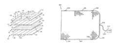
- FIG. 1is an exploded perspective view of a support surface base according to one embodiment of the present invention
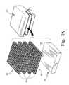
- FIG. 2is an exploded perspective view of another support surface of the present invention including a base, and a plurality of layers of three dimensional engineered material, and an outer cover;
- FIG. 2Ais an exploded perspective view of yet another support surface of the present invention including a base, and a plurality of layers of three dimensional engineered material, and an outer cover;
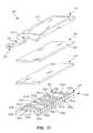
- FIG. 3is an exploded perspective view of another embodiment of the present invention similar to FIG. 2 in which the contoured base is also formed to include a recessed portion configured to receive at least one layer of three dimensional engineered material therein;
- FIG. 4is a side elevational view of another cushion structure of the present invention.
- FIG. 5is a top view of the cushion structure of FIG. 4 ;
- FIG. 6is a bottom view of the cushion structure of FIGS. 4 and 5 ;
- FIGS. 7A to 7Gare sectional views taken along lines 7 - 7 of FIG. 4 ;
- FIG. 8is a sectional view taken along lines 8 - 8 of FIG. 4 ;
- FIG. 9is a view illustrating components of a top foam layer of a foam base configured to be inserted into an interior region of a cover shown in FIGS. 4-8 ;
- FIG. 10is a view illustrating components of a middle foam layer of the base
- FIG. 11is a view illustrating components a bottom foam layer of the base
- FIG. 12is a perspective view a mattress in accordance with the present invention.
- FIG. 13is a perspective view of a support comprising a first layer having a plurality of air bladders and a second layer including a spacing structure;
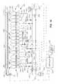
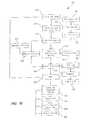
- FIG. 14is a diagrammatic side vide of the support FIG. 13 coupled to an air pressure control system
- FIGS. 15-18are flowcharts corresponding to a first exemplary patient support program to be executed by a controller of the support shown in FIGS. 13 and 14 .
- One embodiment of the present inventionincludes a base 10 upon which the three dimensional engineered material or the indented fiber layers are placed.
- the base 10includes a plurality of layers of foam with each layer comprising a plurality of sections or strips of foam such as shown in FIG. 1 .
- the FIG. 1 embodimentcomprises four separate layers 12 , 14 , 16 , 18 with each layer comprising a plurality of strips as illustrated.
- the stripsare illustratively bonded together at their edges using conventional bonding techniques.
- the stripshave various ILD ratings to provide desired support characteristics.
- Lower layer 12has its two outside strips 20 which are illustratively made from 150 ILD rating foam while the three central strips 22 are made from 60 ILD rating foam.
- the base 10 of FIG. 1is a lattice structure in which the strips comprising the lower layer 12 are extending from front-to-back while the strips comprising the second layer 14 are extending transversely or side-to-side.
- the layer 14comprises five transversely extending strips, the front and back strips 24 , 26 being, for example, of 90 ILD rating foam.
- the three central strips 28 comprising the second layer 12may be made from a foam having a softer or more deformable ILD rating.
- the third layer 16is constructed such that each of its side strips 30 are made from 60 ILD rating foam while its three central strips 32 are made from 30 ILD rating foam as illustrated in FIG. 1 .
- the uppermost layer 18has a pair of side strips 34 (extending front-to-back) made from 60 ILD foam.
- the upper layer 18also has three transversely extending small pieces 36 at the back of the cushion with ILD ratings of 150, three centrally located sections 38 , 40 , 42 having a 30 ILD rating, and two side small sections 44 , 46 have a 60 ILD rating. It will be appreciated that when these layers 12 , 14 , 16 , 18 are superimposed together, the side edges (front-to-back) are provided largely by foam strips with higher ILD ratings including the first layer 12 side strips 20 with 150 ILD ratings and the third layer 16 with side strips 30 of 60 ILD ratings and the upper layer 18 with its side strips 34 with 60 ILD ratings.
- the foam base 10has lower ILD rating foam.
- foam strips with higher ILD ratingsincluding the 90 ILD rating strip 26 in the second layer 14 and the 150 ILD rating strips 36 in the upper layer 18 provide significant rigidity at the back.
- a cushion base 50is formed by sculpting a single piece of foam 52 or a piece of foam made from various composite components bonded together to have the contour recessed portions 54 shown in FIG. 2 configured to match a person's anatomy.
- the present itincludes placing above such a foam base 10 , 50 , one or more indented fiber layers or other such three dimensional engineered material layers over the base 10 , 50 .
- foam base 10 , 50 and the plurality of layers 60are then encased in a cover 62 as shown in FIG. 2 and FIG. 2A . Details of the three dimensional engineered material layers are discussed above.
- a sculptured molded foam base 70includes a contoured center portion 72 and is a cutout or recessed section 74 which is filled with at least one layer of three dimensional engineered material 76 .
- a plurality of layers 60 similar to FIG. 2are then placed over base 70 .
- Base 70 and layers 60are then located inside cover 62 .
- FIGS. 4-11Another embodiment of the present invention is illustrated in FIGS. 4-11 .
- FIGS. 4-8illustrate a cushion 80 having a top surface 82 and surrounding piping 84 .
- Side walls 86are illustratively made from heavy material which permits air to pass through.
- a zipper 88is provided adjacent a rear portion 90 of the cushion 80 to provide access to an interior region.
- a handle 92is coupled to a bottom surface 94 adjacent a front portion 96 of the cushion 80 .
- FIG. 6illustrates additional details of the handle 92 .
- Handle 92includes a central gripping portion 98 and ends 100 and 102 which are coupled to the bottom surface 94 by suitable means such as sewing, RF welding, or other suitable attachment.
- a label 104is also located on the bottom surface 94 .
- the cushion 80includes a plurality of layers of three dimensional engineered material 106 located adjacent top surface 82 .
- Top surface 82is illustratively made from a breathable material such as Lycra.
- the three dimensional engineered material 106is illustratively coupled to the outer piping 84 by suitable attachment such as stitching, welding, gluing, etc. at a plurality of locations as indicated by reference number 108 in FIGS. 7 and 8 . Therefore, the engineered material layers 106 are permitted to float or move relative to the top surface 82 of the cushion 80 .
- Illustrative examples of the different types of three dimensional engineered material 106are discussed above.
- the layer of the three dimensional engineered material 106is provided within the cover 62 of the cushion 80 .
- Cushion 80further includes an inner plastic cover 122 surrounding a foam base 124 .
- the foam base 124can be a single piece of foam, a plurality of foam sections having different densities and ILDs stacked lengthwise or widthwise, or a plurality of layers of foam having different densities and ILDs.
- a base 240includes a foam base 242 and an air base 244 .
- FIG. 7Cillustrates a base 246 of air.
- FIG. 7Dillustrates a base 248 of water.
- FIG. 7Eillustrates a base 250 of springs.
- FIG. 7Fillustrates a base 250 of beads.
- FIG. 7Gillustrates a base 254 of gel.
- a fire sock 126is located between the plastic cover 122 and the foam base 124 .
- Bottom surface 94is illustratively made from an anti-skid material such as a dipped open weave nylon material.
- FIGS. 9-11Another embodiment of the foam base is illustrated in FIGS. 9-11 .
- a top layer 130 of foam base 124is illustrated in FIG. 9 .
- a middle layer 132 of foam base 124is illustrated in FIG. 10
- a bottom layer 134 of foam base 124is illustrated in FIG. 11 . It is understood that all the separate foam sections are glued together to form a substantially continuous layer of material for each of the three layers 130 , 132 , 134 .
- Top layer 130is glued to middle layer 132
- middle layer 132is glued to the bottom layer 134 .
- Each of the foam sectionsis labeled with designations A, B, C, or D. These designations indicate the ranges of densities, and ILDs of the various foam sections to be discussed.
- the specifications for the foam sectionsare illustratively as follows:
- Top foam layer 130includes outer sections 136 illustratively having a length dimension 138 of 16 inches and width dimension 140 of 4 inches. Two sections 142 and 144 are located adjacent a back portion of top layer 130 . In other words, section 142 is located adjacent back portion 90 within the cushion 80 . Sections 142 and 144 each have a width dimension 146 of 10 inches and a length dimension 148 of 4 inches. Top layer 130 further includes front sections 150 , 152 and 154 . Sections 150 and 154 each have length dimensions 156 of 8 inches and width dimensions 158 of 4 inches. Central section 152 has a length dimension of 8 inches and a width dimension 160 of 2 inches. It is understood that dimensions used in FIGS. 9-10 are for illustrative purposes only. Sections having different widths and lengths may be used depending upon the size of the cushion and firmness characteristics desired.
- Middle layer 132is illustrated in FIG. 10 .
- Middle layer 132includes three back sections 162 , 164 , and 166 .
- Outer back sections 162 and 166each have a length dimension 168 of 2 inches and a width dimension 170 of 6.5 inches.
- Center back section 164has a length of 2 inches and a width dimension 172 of 5 inches.
- Middle layer 132further includes two low density, low ILD layers 174 and 176 . Layers 174 and 176 each have a length dimension 178 of 4 inches and a width dimension 180 of 18 inches.
- a slightly higher ILD section 182is located adjacent section 176 .
- Section 182has a width dimension of 18 inches and a length dimension 184 of 2 inches.
- Middle layer 132further includes a plurality of front foam sections 186 , 188 , 190 , 192 , and 194 .
- Outer sections 196 and 194have a length dimension 196 of 4 inches and a width dimension 198 of 4 inches.
- Sections 188 and 192each have a width dimension 200 of 2 inches and length dimension of 4 inches.
- Center section 190has a length dimension of 4 inches and a width dimension 202 of 6 inches.
- Bottom layer 134is illustrated in FIG. 11 .
- bottom layer 134includes five sections 204 , 206 , 208 , 210 , and 212 extending front to back.
- Outer sections 204 and 212have a high density arid high ILD.
- Outer sections 204 and 212each have a length dimension 214 of 16 inches and width dimension 216 of 4 inches.
- Sections 206 and 210are located inwardly of outer sections 204 and 212 , respectively.
- Sections 206 and 210each have a low density and low ILD.
- Sections 206 and 210have a length dimension of 16 inches and a width dimension 218 of 4 inches.
- Center portion 208has a relatively high ILD.
- Central section 208has a length dimension of 16 inches and a width dimension 220 of 2 inches. After the top layer 130 , the middle layer 132 , and the bottom layer 134 are all coupled together to form a base 124 , the base 124 is inserted into the cover 62 as illustrated above to form an improved seating cushion 80 .
- a fan 222is coupled to the cushion 80 .
- fan 222is coupled to the cushion 80 by a tube 224 as shown in FIG. 8 .
- Fan 222may be packaged to sit on the floor or may include a bracket for coupling the fan 222 to a wheelchair, chair, bed, etc.
- the fan 222forces air through the three dimensional engineered material 106 and top surface 82 to provide cooling for a person situated on the cushion 80 .
- the apparatus of the present inventionmay also be used in a mattress or other support surface 230 .
- the zones of the mattress 230are illustratively made from foam sections having different densities and ILD ratings.
- the mattress 230includes a foot end 232 having three dimensional engineered material 234 located therein above foam layers 236 and 238 .
- the fan 222may also be coupled to the support structure illustrated in FIG. 12 to provide air flow and cooling through zone 232 .
- the support described above including the spacing structureis provided as an overlay to a second support comprising a plurality of air bladders configured to provide at least one type of therapy including alternating pressure therapy, percussion and vibratory therapy, or rotational therapy.
- alternating pressure therapy, percussion or vibration therapy, rotational therapy, and the configurations of a support to perform the sameare shown in U.S. Pat. No. 4,949,414 issued Aug. 21, 1990 to Thomas et al. titled “Modular Low Air Loss Patient Support System and Methods for Automatic Patient Turning and Pressure Point Relief,” the disclosure of which is herein, expressly incorporated by reference and U.S. Pat. No. 6,415,814 issued on Jul. 9, 2002 to Barry D. Hand et al.
- the overlay support including the spacing structureis generally a sealed overlay.
- the overlay supportincludes a cover made from a breathable material.
- the overlay support including the spacing structureis configured to provide a low air loss therapy.
- Support 300includes a first layer 302 configured to provide at least one type of therapy including alternating pressure therapy, percussion and vibratory therapy, or rotational therapy including a plurality of air bladders 304 a - p and a second layer 306 including a spacing structure 308 .
- Spacing structure 308in one embodiment comprises one or more indented fiber layers or other such three dimensional engineered material layers having a plurality of resilient members. In one example the SPACENET® material is used as spacing structure 308 .
- first layer 302provides a generally constant pressure profile across air bladder 304 a - p .
- first layer 302is configured such that combinations of adjacent air bladders 304 a - p define body support zones which support different portions of the patient at different pressures.
- first layer 302is configured to provide an alternating pressure therapy wherein every other or every third or other multiple of air bladders 304 a - p are plumbed together to define bladder sets such that a patient may be supported by first layer 302 while simultaneously relieving pressure points by cyclically dropping and/or elevating the pressure in the respective bladder sets.
- all of air bladders 364 a - pprovide an alternating pressure therapy.
- At least two of the air bladders 304 a - pprovide an alternating pressure therapy.
- at least one of the air bladders 304 a - pis configured to provide a percussion therapy wherein the pressure of the at least one air bladder 304 a - p is dropped and elevated at a rate sufficient to and amount to impart a vibration to the patient.
- the vibrationis directed at a chest region of the patient to aid in the breakdown of undesired materials in the lungs of the patient.
- at least one of air bladders 304 a - pis configured to provide a rotational therapy to the patient.
- an impermeable sheet 310is positioned between spacing structure 308 and the plurality of air bladders 304 a - p and is configured to keep fluids and moisture away from bladders 304 a - p .
- a cover 312overlays spacing structure 308 and is secured to impermeable sheet 310 with a suitable fastener 311 .
- suitable fastenersinclude snaps, hook and loop fasteners, or zippers. As such, cover 312 and impermeable sheet 310 cooperate to enclose spacing structure 308 within an interior region between cover 312 and impermeable sheet 310 .
- spacing structure 308impermeable sheet 310 , and cover 312 is portable and can be placed upon any suitable support layer, such as first layer 302 including plurality of bladders 304 a - p . It is further contemplated that cover 312 , and/or impermeable sheet 310 is configured to be secured to first layer 302 with a suitable fastener.
- the cover and the impermeable sheetare made as a single unit or bag with an opening wherein the spacing structure is placed in an interior region thereof.
- the openingis closed with any suitable fasteners, such as snaps, hook and loop fasteners, or zippers.
- the single unit or bagmay then be placed upon and/or coupled to any suitable support layer, such as first layer 302 including plurality of bladders 304 a - p.
- a top portion 314 of first layer 302such as the top portions of air bladders 304 a - p are made from an impermeable material and combine to form an impermeable sheet.
- spacing structure 308is placed in the interior region formed by cover 312 add the impermeable sheet created by the top portion of the first layer.
- Cover 312is secured to first layer 302 with any suitable fasteners, such as snaps, hook and loop fasteners, or zippers.
- the coveris a single unit or bag with an opening wherein spacing structure 308 and first layer 302 including the impermeable sheet formed from the top portion of first layer 302 are placed in an interior thereof. As such, the cover encloses both the first layer and the second layer.
- the coveris a single unit with an opening wherein spacing structure 308 is placed.
- the cover and spacing structure 308are then positionable and/or securable to first layer 302 .
- the coveris interposed between the impermeable sheet of first layer 302 and spacing structure 308 .
- a top portion 315 of cover 312is made from a moisture vapor permeable material which allows air and moisture to pass there through.
- a coupler 318is attached to cover 312 and is configured to be coupled to a source of air, such as fan 320 , through a tube 322 .
- air supplied by fan 320passes through tube 322 and enters the interior region between cover 312 and impermeable sheet 310 through opening 316 in cover 312 .
- the air entering opening 316is forced through spacing structure 308 and exits top portion 315 of cover 312 to provide cooling for a person being supported by support 300 .
- fan 320includes a heating element such that the air provided to the interior region may be heated above the ambient temperature.
- controller 334controls the heating element and thus the temperature of the air.
- cover 312includes a plurality of apertures in the top portion to provide low air loss therapy.
- top portion 315 of cover 312is formed to contain a heating element such as GorixTM material. Controller 334 is electrically coupled to the heating element. The heating element is used to warm the patient on support 300 .
- An example support incorporating a heating materialis disclosed in copending U.S. patent application Ser. No. 09/701,499, now U.S. Pat. No. 6,582,456, filed on Nov. 29, 2000 by Hand et al. and titled “Heated Patient Support Apparatus,” the disclosure of which is herein, expressly incorporated by reference.
- first layer 302is combined with a low air loss layer comprising a plurality of air chambers such as the mattress assembly shown in at least one of U.S. Pat. No. 5,794,288 issued on Aug. 18, 1998 to Soltani et al. titled “Pressure Control Assembly for an Air Mattress,” U.S. Pat. No. 6,240,584 issued on Jun. 5, 2001 to Perez et al titled “Mattress Assembly,” and the SilkAir® Therapy System both sold by Hill-Rom located in Batesville, Ind. and at 4349 Corporate Road, Charleston, S.C. 29405.
- support 300does not provide low air loss therapy
- cover 312 of support 300still overlays spacing structure 308 as described above, however cover 312 does not include a portion made from a moisture vapor permeable material.
- Support 300does further include a pad (not shown) including a wicking material that is positionable upon cover 312 and securable to cover 312 or other portions of support 300 .
- the wicking materialis configured to pull moisture away from the patient positioned on the pad such that the skin of the patient can be kept generally dry.
- a width of individual air bladders 304 a - p of first layer 302illustratively such as a width 305 of air bladder 304 a is preferably between about 1 inch to about 2.5 inches, between about 1 inch to about 2 inches, or between about 1.5 inches to about 2.5 inches and a height of individual air bladders 304 a - p , illustratively, such as a height 307 of air bladder 304 a is about 6 inches to about 8 inches.
- the preferred width 305 of air bladder 304 areduces the amount of shear experienced by a patient lying on support 300 when at least a portion of support 300 is configured to provide alternating pressure as compared to larger bladder widths, such as about 6 inches to about 8 inches.
- first layer 302is divided into a plurality of support zones 324 a - d .
- Support zone 324 agenerally corresponds to the leg and foot region of the patient supported on support 300 .
- Support zone 324 bgenerally corresponds to the seat and thigh region of the patient supported on support 300 .
- Support zone 324 cgenerally corresponds to the chest region of the patient supported on support 300 .
- Support zone 324 dgenerally corresponds to the head region of the patient supported on support 300 .
- four support zonesare shown, it is within the scope of the present invention to have various configurations comprising one or more support zones.
- Each support zone 324 a - dcontains at least one bladder 304 and preferably includes a plurality of bladders. As shown in FIGS. 13 and 14 , support zone 324 a includes bladders 304 a - d , support zone 324 b includes bladders 304 e - j , support zone 324 c includes bladders 304 k and 304 l , and support zone 324 d includes bladders 304 m - p. Further, it is within the scope of the present invention to vary either the overall number of air bladders or the number of air bladders in at least one support zone or both.
- Airis supplied to each bladder 304 a - p through bladder supply lines 326 a - p coupled to respective bladders 304 a - p as illustratively shown in FIG. 14 .
- Bladder supply lines 326 a - pare supplied by one of two main supply lines 328 a and 328 b .
- a single main supply lineis coupled to all of the bladder supply lines.
- three or more supply linesare coupled to various groupings of air bladders.
- each bladder supply line 326 a - pis coupled to either main supply line 328 a or main supply line 328 b through a fixed valve 330 or a three-way valve 332 .
- bladders 304 a and 304 care coupled to line 328 a through fixed valve 330 a
- bladders 304 b and 304 dare coupled to line 328 b through fixed valve 330 b
- bladders 304 e , 304 g , and 304 iare coupled to line 328 a through three-way valve 332 a
- bladders 304 f , 304 h , and 304 jare coupled to line 328 b through three-way valve 332 b
- bladder 304 kis coupled to line 328 a through fixed valve 330 c
- bladder 304 lis coupled to line 328 b through fixed valve 330 d
- bladders 304 m and 304 oare coupled to line 328
- FIG. 14The configuration shown in FIG. 14 is for illustrative purposes and it is within the scope of the present invention to use only three-way valves, only fixed valves, or other configurations of three-way valves and fixed valves to couple the air bladders to the supply lines. Further it is within the scope of the present invention to use variable valves such as electronic control valves.
- Fixed valves 330 a - fare configured to control the rate of flow into and out of corresponding air bladder 304 a - d , 304 k and 304 l , and 304 m - p .
- fixed values 330 a - feach are configured to permit the same rate of fluid flow into and out of corresponding air bladder 304 a - d , 304 k and 304 l , and 304 m - p .
- fixed valves 330 of at least one support zone 324 of support zones 324 a - dis configured to permit a different rate of fluid flow into and out of the corresponding bladders 304 , such that the at least one support zone is inflatable to a different pressure than the remaining support zones.
- at least one of fixed valves 330 a - fis replaced with a variable valve wherein the rate of fluid flow into and out of the corresponding bladder 304 is adjustable.
- the variable valveis an electronic control valve that is configured to communicate with controller 334 and to adjust the rate of flow based on a signal provided by controller 334 .
- Three-way valves 332 a and 332 bare configured to couple respective air bladders 304 e , 304 g , 304 i and 304 f , 304 h , 304 j to respective supply lines 328 a and 328 b in a first orientation and to vent respective air bladders 304 e , 304 g , 304 i and 304 f , 304 h, 304 j to atmosphere in a second orientation.
- Three-way valves 332 a and 332 bare provided in zone 324 b to permit zone 324 b to provide a percussion therapy while zones 324 a , 324 c , and 324 d maintain a constant pressure profile or provide an alternating pressure therapy.
- zones 324 a , 324 c , and 324 dare held at a constant pressure profile, although potentially a different pressure profile for each respective zone, and zone 324 b is configured to provide an alternating pressure therapy or a percussion therapy.
- zones 324 a , 324 c , and 324 dare configured to provide an alternating pressure therapy and zone 324 b is configured to provide a percussion therapy.
- airis supplied to bladders 304 a - p from supply lines 328 a and 328 b .
- Supply lines 328 a and 328 bare coupled to an air supply, such as pump 336 , through three-way valves 340 a and 340 b , respectively.
- Any air supply and three-way valves 340 a and 340 b known to one skilled in the art of mattresses and hospital equipmentcan be provided for the operation of the present invention.
- Three-way valves 340 a and 340 bare configured to couple corresponding main supply lines 328 a and 328 b to air supply 336 in a first orientation and to couple corresponding main supply lines 328 a and 328 b to atmosphere in a second orientation.
- pump 336When pump 336 is coupled to at least one of supply lines 328 a and 328 b , the pressure in the at least one of supply lines 328 a and 328 b is proportional to the output of pump 336 .
- Pressure sensors 344 a and 344 bmonitor the pressure in the respective supply lines 328 a and 328 b.
- Controller 334is configured to control the operation of pump 336 , three-way valves 332 a and 332 b , and three-way valves 340 a and 340 b . Further, if any of fixed valves 330 a - f are variable valves, such as electronic control valves, controller 334 can control the variable valve. Further, pressure sensors 344 a and 344 b are connected to controller 334 such that controller 334 can monitor the pressure of supply lines 328 a and 328 b .
- pressure sensorsare provided between bladders 304 a - p and valves 330 a - f and 332 a and 332 b such that controller 334 can monitor the pressure of the air supplied to air bladders 304 a - p .
- pressure sensorsare provided in the interior of at least one of air bladders 304 a - p such that controller 334 can monitor the pressure inside the at least one of air bladders 304 a - p.
- Exemplary controllers, valves, pressure sensors, and overall air pressure systemsare shown in U.S. Pat. No. 6,212,718 issued on Apr. 10, 2002 to Stolpmann et al. titled “Air-Over-Foam Mattress” and in the PrimeAire® Therapy Surface sold by Hill-Rom located in Batesville, Ind. and at 4349 Corporate Road, Charleston, S.C. 29405.
- Controller 334is further configured to control fan 320 , such that fan 320 is configured to force air through tube 322 into the interior region between cover 312 and impermeable sheet 310 .
- Portion 315 of cover 312is made from a moisture vapor permeable material that allows air and moisture to pass there through. The air entering the interior region from fan 320 is forced through spacing structure 308 and portion 315 to provide a low air loss therapy wherein a person being supported by support 300 is cooled due to the movement of air.
- the controller 334maintains the proper amount of air movement provided by fan 320 .
- each air bladder 304 a - p, under the direction of controller 334may individually be coupled to a supply line of pressurized air such as 328 a or coupled atmosphere.
- fixed valves 330 a - f and three-way valves 332 a and 332 bare replaced with check valves and control orifices which are configured to control the supply of air to each air bladder 304 a - p . Further, each air bladder is connected to an exhaust line which is coupled to atmosphere.
- An exemplary configuration of check valves, control orifices and exhaust linesis provided in U.S. Pat. No. 5,794,288 to Soltani et al. titled “Pressure Control Assembly for an Air Mattress,” the disclosure of which is herein expressly incorporated by reference.
- FIG. 14further shows a power supply 342 configured to supply electrical power to drive support 300 .
- power supply 342is connected to controller 334 and from controller 334 provides the power for the rest of the system, including fan 320 and pump 336 .
- power supply 342is directly connected to at least one additional component, such as pump 336 or fan 320 .
- support 300has illustratively been shown as having four support zones 324 a - d , it is within the scope of the present invention to have only a single support zone spanning the length of support 300 .
- the single support zoneprovides a constant pressure profile across air bladders 304 a - p .
- the single support zoneprovides an alternating pressure therapy wherein either every other, every third, or other multiples of air bladders 304 a - p are plumbed together.
- Patient support software 360is configured to be executed by controller 334 in association with the operation of support 300 .
- controller 334 and support 300are turned on or powered up, as represented by block 362 .
- the operatoris able to selects at least one of three therapies: a low air loss therapy 366 , an alternating pressure therapy 368 , or a percussion therapy 370 .
- a low air loss therapy 366alternating pressure therapy 368
- a percussion therapy 370is substituted by a rotational therapy (not shown).
- air bladders 304 a - p of support 300are divided into two sets of air bladders, right side air bladders (not shown) and left side air bladders (not shown).
- Exemplary air bladders for use with a rotational therapyare shown in U.S. Pat. No. 4,949,414 issued Aug. 21, 1990 to Thomas et al. titled “Modular Low Air Loss Patient Support System and Methods for Automatic Patient Turning and Pressure Point Relief,” the disclosure of which is herein expressly incorporated by reference and U.S. Pat. No. 6,415,814 issued on Jul. 9, 2002 to Barry D. Hand et al. and titled “Vibratory Patient Support System,” the disclosure of which is herein expressly incorporated by reference.
- controller 334turns on pump at block 364 such that bladders 304 a - p are inflated to a start-up pressure profile stored in controller 334 .
- fan 320is activated with initial settings stored in controller, as represented by block 374 .
- the pressure of bladders 304 a - pare set such that a pressure profile is established or stored, as represented by block 376 .
- the terms “pressure profile”are used to refer to the fact that the pressure in each support zone 324 a - d may be different because of the different support requirements of that particular zone. For example, the pressure in the support zone corresponding to the feet of the body may be lower than one or more of the other support zones to provide pressure relief to the heel of the body.
- the pressure profileis determined based on input from a caregiver.
- a caregiverselects a pressure set input from a caregiver interface (not shown) connected to support 300 , as represented by block 378 .
- the caregiverenters the weight of the patient lying on support 300 , as represented by block 380 , and controller 334 through an algorithm sets the appropriate pressure profile, as represented by block 382 .
- An example of setting of a pressure profile based on at least the weight of a patient in a support having multiple support zones and a caregiver interfaceare shown in U.S. Pat. No. 4,949,414 issued Aug. 21, 1990 to Thomas et al.
- controller 334checks to determine if percussion control valves 332 a and 332 b need to be turned off, as represented by block 384 .
- Percussion control valves 332 a and 332 bare in an on configuration or “turned on” when they are being cycled between the first orientation and the second orientation at a rate that corresponds to percussion therapy 370 , as discussed below in connection with blocks 412 and 414 in FIG. 18 .
- Percussion control valves 332 a and 332 bare in an off configuration or “turned off” when they are held in either the first orientation or the second orientation, preferably the first orientation wherein air bladders 304 e - j are connected to respective supply lines 328 a and 328 b . However, if low air loss therapy 366 is to be conducted simultaneously with percussion therapy 370 , block 384 is disabled.
- Controller 334monitors the pressure profile of bladders 304 a - p , as represented by block 386 . Adjustments to the pressure profile can be made, as represented by block 388 .
- One example adjustmentis a manual offset from a patient comfort input, as represented by block 390 .
- an input devicesuch as a control panel (not shown) may be accessed by a patient in order that the patient can either increase the pressure or reduce the pressure in the patient support or in a given zone of the patient support.
- adjustments to the pressure profileare made due to a change in the position of the patient on support 300 or the orientation of support 300 , such as a head section (not shown) of a bed (not shown) on which support 300 is positioned is tilted upward.
- Controller 334sets or stores the adjustments to the pressure profile.
- controller 334detects a low pressure in either supply line 328 a or 328 b through pressure sensors 344 a and 344 b or a low pressure in at least one of bladders 304 a - p , a low pressure alarm is set, as represented by block 392 .
- Controller 334waits for a predefined time interval to see if the pressure is restored to a generally normal level, as represented by block 394 . If the pressure has not been restored upon the expiration of the time interval an alarm is initiated, such as the lighting of an LED, as represented by block 396 .
- the alarmis an audible alarm, a light positioned remote from support 300 such as in the hallway or at a nurse's station, or a signal across a network (not shown) to a caregiver station.
- Controller 334continues to execute the base routine of low air loss therapy 366 in the absence of a change in command, as represented by blocks 398 and 400 .
- a command change, as represented by block 400is the selection of another or an additional therapy.
- example changes in commandinclude a request to power off support 300 , as represented by block 402 , a request to cycle or turn off the low air loss fan 320 , as represented by block 404 , and to pause the system, as represented by block 406 .
- pausing the systemindicates to controller 334 to hold the current pressure in air bladders 304 a - p .
- pausing the systemindicates to controller 334 to adjust the pressure in air bladders 304 a - p to a stored pressure profile.
- Alternating pressure therapy routine 368is generally similar to low air loss therapy routine 366 . As such like numerals are positioned on like blocks that are common to both alternating pressure routine 368 and low air loss routine 366 . Further, if alternating pressure therapy 368 is to be conducted simultaneously with percussion therapy 370 , block 384 is disabled. Alternating pressure therapy 368 differs from low air loss therapy 366 in that a cycle time is selected, as represented by block 408 . Controller 334 sets the cycle time as represented by block 410 .
- alternating pressure therapy 368corresponds to plumbing every second, every third, or higher multiple of air bladders 304 a - p together to define at least two groups of support bladders.
- a first bladder groupconsists of air bladders 304 a , 304 c , 304 e , 304 g , 304 i , 304 k , 304 m , and 304 o and a second bladder group consists of air bladders 304 b , 304 d , 304 f , 304 h , 304 j, 304 l , 304 n , and 304 p.
- the pressure in the first illustrated bladder group and the second illustrated bladder groupcorresponds to the stored constant pressure profile for support 300 .
- the pressure in the first groupis adjusted to a higher pressure than the pressure in the second group and then the pressure in the first group is adjusted to a lower pressure than the pressure in the second group.
- a first cyclecorresponds to in a first step holding the pressure in the first group of air bladders and dropping the pressure in the second group of air bladders to a predetermined pressure profile or by a predetermined percentage of pressure, holding the resultant pressures in the first group and the second group for a first time period in a second step, in a third step restoring the pressure in the second group of air bladders and dropping the pressure in the first group of air bladders, to a predetermined pressure profile or by a predetermined percentage of pressure, holding the resultant pressures for a second time period in a fourth step, and then restoring the pressure in the first group of air bladders and dropping the pressure in the second group of air bladders, such that support 300 is in the configuration provided in step one.
- Subsequent cyclesconsist of repeating steps two through five. If the alternating pressure therapy is terminated, the pressure in both the first group of air bladders and the second group of air bladders is restored.
- the first time period and the second time periodcorrespond to about 3 minutes to about 5 minutes.
- a first cyclecorresponds to in a first step holding the pressure in the first group of air bladders and elevating the pressure in the second group of air bladders to a predetermined pressure profile or by a predetermined percentage of pressure, holding the resultant pressures in the first group and the second group for a first time period in a second step, in a third step restoring the pressure in the second group of air bladders and elevating the pressure in the first group of air bladders, to a predetermined pressure profile or by a predetermined percentage of pressure, holding the resultant pressures for a second time period in a fourth step, and then restoring the pressure in the first group of air bladders and elevating the pressure in the second group of air bladders, such that support 300 is in the configuration provided in step one.
- Subsequent cyclesconsist of repeating steps two through five. If the alternating pressure therapy is terminated, the pressure in both the first group of air bladders and the second group of air bladders is restored.
- the first time period and the second time periodcorrespond to about 3 minutes to about 5 minutes.
- a first cyclecorresponds to in a first step elevating the pressure in the first group of air bladders to a predetermined pressure profile or by a predetermined percentage of pressure and dropping the pressure in the second group of air bladders to a predetermined pressure profile or by a predetermined percentage of pressure, holding the resultant pressures in the first group and the second group for a first time period in a second step, in a third step elevating the pressure in the second group of air bladders to a predetermined pressure profile or by a predetermined percentage of pressure and dropping the pressure in the first group of air bladders to a predetermined pressure profile or by a predetermined percentage of pressure, holding the resultant pressures for a second time period in a fourth step, and then elevating the pressure in the first group of air bladders to a predetermined pressure profile or by a predetermined percentage of pressure and dropping the pressure in the second group of air bladders to a predetermined pressure profile or by a predetermined percentage of pressure, such that support 300 is in the configuration provided in step one.
- Subsequent cyclesconsist of repeating steps two through five. If the alternating pressure therapy is terminated, the pressure in both the first group of air bladders and the second group of air bladders is restored.
- the first time period and the second time periodcorrespond to about 3 minutes to about 5 minutes.
- Percussion therapy routine 370is generally similar to low air loss therapy routine 366 and alternating pressure therapy routine 368 . As such like numerals are positioned on like blocks that are common to percussion therapy routine 370 and both alternating pressure routine 368 and low air loss routine 366 . Percussion therapy routine 370 differs from low air loss therapy 366 in that a percussion rate is selected, as represented by block 412 . Controller 334 turns on percussion valves 332 a and 332 b and initiates the percussion therapy, as represented by block 414 .
- three-way valves 332 a and 332 bare configured to couple respective air bladders 304 e , 304 g , 304 i and 304 f , 304 h , 304 j to respective supply lines 328 a and 328 b in a first orientation and to vent respective air bladders 304 e , 304 g, 304 i and 304 f , 304 h , 304 j to atmosphere in a second orientation.
- three-way valve 332 acouples air bladders 304 e , 304 g and 304 i to supply line 328 a and three-way valve 332 b couples air bladders 304 f , 304 h and 304 j to atmosphere to quickly reduce the pressure in air bladders 304 f , 304 h and 304 j .
- three-way valve 332 acouples air bladders 304 e , 304 g and 304 i to atmosphere to quickly reduce the pressure in air bladders 304 e , 304 g and 304 i and three-way valve 332 b couples air bladders 304 f, 304 h and 304 j to supply line 328 b to pressurize air bladders 304 f , 304 h and 304 j .
- the rate selected for the percussion therapycorresponds to cycling between the first orientation and the second orientation at about 1 Hertz to about 25 Hertz, at about 1 Hertz to about 5 Hertz, and at about 6 Hertz to about 25 Hertz.
- air bladders 304 e - jinclude vibrating means configured to provide percussion therapy.
- the vibrating meansare disposed within air bladders 304 e - j .
- the vibrating meansdisposed partially within air bladders 304 e - j and partially as a portion of top portion 314 of air bladders 304 e - j .
- Exemplary vibrating meansare shown in U.S. Pat. No. 4,949,414 issued Aug. 21, 1990 to Thomas et al. titled “Modular Low Air Loss Patient Support System and Methods for Automatic Patient Turning and Pressure Point Relief,” the disclosure of which is herein expressly incorporated by reference and U.S. Pat. No. 6,415,814 issued on Jul. 9, 2002 to Barry D. Hand et al. and titled “Vibratory Patient Support System,” the disclosure of which is herein expressly incorporated by reference.
Landscapes
- Health & Medical Sciences (AREA)
- Life Sciences & Earth Sciences (AREA)
- Animal Behavior & Ethology (AREA)
- General Health & Medical Sciences (AREA)
- Public Health (AREA)
- Veterinary Medicine (AREA)
- Nursing (AREA)
- Invalid Beds And Related Equipment (AREA)
Abstract
Description
| Foam Section | Density | ILD | Type | ||
| A | 1.7-1.8 | 40-47 | 1745 | ||
| B | 3.0 | 61-71 | Q61 | ||
| C | 1.7-1.8 | 90-100 | LH96X | ||
| D | 4.0-4.25 | 171-181 | Z171 | ||
Claims (20)
Priority Applications (1)
| Application Number | Priority Date | Filing Date | Title |
|---|---|---|---|
| US14/099,154US9462893B2 (en) | 1998-05-06 | 2013-12-06 | Cover system for a patient support surface |
Applications Claiming Priority (11)
| Application Number | Priority Date | Filing Date | Title |
|---|---|---|---|
| US8441198P | 1998-05-06 | 1998-05-06 | |
| US09/306,601US6269504B1 (en) | 1998-05-06 | 1999-05-06 | Mattress or cushion structure |
| US09/921,317US6701556B2 (en) | 1998-05-06 | 2001-08-02 | Mattress or cushion structure |
| US45497803P | 2003-03-14 | 2003-03-14 | |
| US10/793,723US7191480B2 (en) | 1998-05-06 | 2004-03-05 | Mattress or cushion structure |
| US10/800,952US7191482B2 (en) | 1998-05-06 | 2004-03-15 | Patient support |
| US11/688,407US7480953B2 (en) | 1998-05-06 | 2007-03-20 | Patient support |
| US12/359,387US7617555B2 (en) | 1998-05-06 | 2009-01-26 | Patient support surface |
| US12/619,133US7966680B2 (en) | 1998-05-06 | 2009-11-16 | Patient support surface |
| US13/107,493US8601620B2 (en) | 1998-05-06 | 2011-05-13 | Cover system for a patient support surface |
| US14/099,154US9462893B2 (en) | 1998-05-06 | 2013-12-06 | Cover system for a patient support surface |
Related Parent Applications (1)
| Application Number | Title | Priority Date | Filing Date |
|---|---|---|---|
| US13/107,493ContinuationUS8601620B2 (en) | 1998-05-06 | 2011-05-13 | Cover system for a patient support surface |
Publications (2)
| Publication Number | Publication Date |
|---|---|
| US20140115790A1 US20140115790A1 (en) | 2014-05-01 |
| US9462893B2true US9462893B2 (en) | 2016-10-11 |
Family
ID=50553443
Family Applications (1)
| Application Number | Title | Priority Date | Filing Date |
|---|---|---|---|
| US14/099,154Expired - Fee RelatedUS9462893B2 (en) | 1998-05-06 | 2013-12-06 | Cover system for a patient support surface |
Country Status (1)
| Country | Link |
|---|---|
| US (1) | US9462893B2 (en) |
Cited By (27)
| Publication number | Priority date | Publication date | Assignee | Title |
|---|---|---|---|---|
| USD840175S1 (en)* | 2017-05-08 | 2019-02-12 | Amerisleep International Limited | Foam pad for a mattress |
| US10489661B1 (en) | 2016-03-08 | 2019-11-26 | Ocuvera LLC | Medical environment monitoring system |
| US20190365116A1 (en)* | 2017-05-15 | 2019-12-05 | Dyob, Llc | Modular mattress systems and methods |
| USD877915S1 (en) | 2018-09-28 | 2020-03-10 | Stryker Corporation | Crib assembly |
| US10600204B1 (en) | 2016-12-28 | 2020-03-24 | Ocuvera | Medical environment bedsore detection and prevention system |
| USD879966S1 (en) | 2018-09-28 | 2020-03-31 | Stryker Corporation | Crib assembly |
| USD888963S1 (en) | 2018-09-28 | 2020-06-30 | Stryker Corporation | Cover assembly for a patient support |
| USD888962S1 (en) | 2018-09-28 | 2020-06-30 | Stryker Corporation | Cover assembly for a patient support |
| USD888964S1 (en) | 2018-09-28 | 2020-06-30 | Stryker Corporation | Crib assembly for a patient support |
| USD890914S1 (en) | 2018-10-31 | 2020-07-21 | Stryker Corporation | Pump |
| USD892159S1 (en) | 2018-10-31 | 2020-08-04 | Stryker Corporation | Display screen with animated graphical user interface |
| USD893543S1 (en) | 2018-10-31 | 2020-08-18 | Stryker Corporation | Display screen with graphical user interface |
| USD894223S1 (en) | 2018-10-31 | 2020-08-25 | Stryker Corporation | Display screen with animated graphical user interface |
| USD894226S1 (en) | 2018-10-31 | 2020-08-25 | Stryker Corporation | Display screen or portion thereof with graphical user interface |
| USD894957S1 (en) | 2018-10-31 | 2020-09-01 | Stryker Corporation | Display screen or portion thereof with graphical user interface |
| USD894956S1 (en) | 2018-10-31 | 2020-09-01 | Stryker Corporation | Display screen or portion thereof with graphical user interface |
| US10765227B2 (en)* | 2017-04-21 | 2020-09-08 | Me. Res. S.R.L. | Mattress |
| USD901940S1 (en) | 2018-09-28 | 2020-11-17 | Stryker Corporation | Patient support |
| US11173085B2 (en) | 2017-12-28 | 2021-11-16 | Stryker Corporation | Mattress cover for a mattress providing rotation therapy to a patient |
| US11246775B2 (en) | 2017-12-28 | 2022-02-15 | Stryker Corporation | Patient turning device for a patient support apparatus |
| US11311111B2 (en) | 2020-04-06 | 2022-04-26 | Purple Innovation, Llc | Ventilated mattresses |
| US11540964B2 (en) | 2018-02-27 | 2023-01-03 | Hill-Rom Services, Inc. | Patient support surface control, end of life indication, and x-ray cassette sleeve |
| USD977109S1 (en) | 2018-09-28 | 2023-01-31 | Stryker Corporation | Crib assembly for a patient support |
| US12042440B1 (en) | 2021-04-16 | 2024-07-23 | Turn Medical, LLC | Stowable patient supports |
| US12121479B1 (en) | 2021-04-16 | 2024-10-22 | Turn Medical, LLC | Strap and release system |
| US12226356B1 (en) | 2021-04-16 | 2025-02-18 | Turn Medical, LLC | Adjustable posterior head support |
| US12403057B1 (en) | 2021-04-16 | 2025-09-02 | Turn Medical, LLC | Proning face pack |
Families Citing this family (10)
| Publication number | Priority date | Publication date | Assignee | Title |
|---|---|---|---|---|
| US9462893B2 (en)* | 1998-05-06 | 2016-10-11 | Hill-Rom Services, Inc. | Cover system for a patient support surface |
| US10272786B2 (en) | 2009-04-02 | 2019-04-30 | David Kurt Schneider | Wheelchair safety, power and shade device and method |
| WO2013102777A1 (en)* | 2012-01-05 | 2013-07-11 | Escobar Uribe Andres | Anatomical padding system with multi-level layers |
| US10130533B2 (en)* | 2012-10-24 | 2018-11-20 | David Kurt Schneider | Patient contact compensating wheelchair |
| TWM469845U (en)* | 2013-07-19 | 2014-01-11 | Min-Chia Chang | Structure of mat body |
| US9320666B2 (en) | 2014-02-26 | 2016-04-26 | Prs Medical Technologies, Inc. | Multi-layered cushioning support |
| US11147390B2 (en)* | 2018-10-11 | 2021-10-19 | L&P Property Management Company | Outdoor cushion with pocketed spring interior |
| EP4062885A1 (en)* | 2021-03-26 | 2022-09-28 | Hill-Rom Services, Inc. | Person support systems including separately selectable alternating pressure zones |
| CN113317939B (en)* | 2021-06-02 | 2022-09-13 | 西南医科大学 | A multifunctional physiotherapy device for rehabilitation physiotherapy |
| US20230309708A1 (en)* | 2022-03-31 | 2023-10-05 | Dreamwell, Ltd. | Hybrid mattress core assemblies |
Citations (167)
| Publication number | Priority date | Publication date | Assignee | Title |
|---|---|---|---|---|
| US371938A (en) | 1887-10-25 | Mattress | ||
| US1835212A (en) | 1930-01-28 | 1931-12-08 | Del Roy F Fowler | Reversible spring center mattress |
| US2029370A (en) | 1933-03-06 | 1936-02-04 | Goodrich Co B F | Cushioning structure |
| US2464984A (en) | 1945-10-08 | 1949-03-22 | Air King Products Company Inc | Semireentrant line oscillator for ultra high frequency, comprising an electron discharge device |
| US2493067A (en) | 1945-09-08 | 1950-01-03 | Louis J Goldsmith | Mattress |
| US2742652A (en) | 1952-07-17 | 1956-04-24 | Owens Corning Fiberglass Corp | Cushions and cushioning material |
| CH332754A (en) | 1954-08-13 | 1958-09-30 | Lonza Ag | pad |
| US2901756A (en) | 1952-04-09 | 1959-09-01 | Rex E Moule | Fireproof metal mattress or padding |
| US3000020A (en) | 1958-05-15 | 1961-09-19 | United Tanks Inc | Safety cushion |
| US3030145A (en) | 1953-08-26 | 1962-04-17 | Kushion Kooler Corp | Ventilating seat pad |
| US3047888A (en) | 1960-12-05 | 1962-08-07 | George O Shecter | Cushioning structure |
| US3080578A (en) | 1960-03-28 | 1963-03-12 | Simmons Co | Mattress construction |
| US3210781A (en)* | 1962-01-30 | 1965-10-12 | Harold Van B Pollock | Mattress |
| US3230556A (en) | 1962-05-07 | 1966-01-25 | Shippee Wiusor | Construction for maintaining a controlled temperature environment in a bed |
| US3268922A (en) | 1964-01-02 | 1966-08-30 | John F Moxley | Mattresses |
| US3419920A (en)* | 1966-10-17 | 1969-01-07 | Forrest E. Maddux Jr. | Mattress |
| US3421163A (en) | 1966-11-14 | 1969-01-14 | Joseph B Stoughton | Orthopedic cushion |
| US3521311A (en)* | 1968-03-01 | 1970-07-21 | Paul P Cohen | Mattress |
| US3534417A (en)* | 1968-07-08 | 1970-10-20 | Truman C Boyles | Reversible foam mattress having different degrees of firmness |
| US3580615A (en) | 1968-06-24 | 1971-05-25 | Autotrol Corp | Softener control assembly |
| US3605145A (en) | 1968-12-05 | 1971-09-20 | Robert H Graebe | Body support |
| US3644950A (en) | 1969-08-01 | 1972-02-29 | Milton Roy Co | Patient support system |
| US3846857A (en)* | 1972-03-10 | 1974-11-12 | Neurological Res And Dev Group | Multi-section variable density mattress |
| US3939508A (en) | 1975-01-08 | 1976-02-24 | Thomasville Products, Inc. | Mattress and cushioning construction |
| US3974532A (en) | 1975-03-10 | 1976-08-17 | Mitsuyoshi Hamasu | Padding for mattresses and like articles |
| US4086675A (en)* | 1977-01-05 | 1978-05-02 | Thomasville Products, Inc. | Reinforced edge construction for cushions |
| US4347633A (en) | 1980-07-22 | 1982-09-07 | American Hospital Supply Corporation | Patient treating mattress |
| US4449261A (en) | 1981-06-22 | 1984-05-22 | Simmons U.S.A. Corp. | Bed mattress having an improved pillow top |
| US4485505A (en) | 1980-08-13 | 1984-12-04 | Paul Patrick R D | Ventilating, inflatable mattress |
| US4486909A (en) | 1980-06-02 | 1984-12-11 | Mckneelan Robert L | Means for anchoring sheet to waterbed |
| US4494775A (en) | 1982-09-30 | 1985-01-22 | William Nash Company, Inc. | Fluid coupling |
| US4522447A (en) | 1980-02-02 | 1985-06-11 | Snyder William F | Foam seat and back cushions |
| US4555130A (en) | 1983-04-01 | 1985-11-26 | The United States Of America As Represented By The Secretary Of The Navy | Diver's umbilical quick-disconnect device |
| US4580301A (en) | 1982-11-19 | 1986-04-08 | Courtaulds Plc | Mattress for supporting the human body |
| US4631221A (en) | 1984-04-05 | 1986-12-23 | Hoechst Aktiengesellschaft | Sheet-like sandwich molding |
| US4638519A (en) | 1985-04-04 | 1987-01-27 | Air Plus, Inc. | Fluidized hospital bed |
| GB2181048A (en) | 1985-10-04 | 1987-04-15 | Bernard Bedborough | Overlay |
| US4706313A (en) | 1986-05-01 | 1987-11-17 | Comfortex, Inc. | Decubitus ulcer mattress |
| US4753480A (en) | 1986-08-14 | 1988-06-28 | Morell Theodore R | Pad assembly for wheelchairs |
| US4768251A (en)* | 1987-03-30 | 1988-09-06 | Convo Corporation | Mattress pad |
| US4777681A (en) | 1986-01-10 | 1988-10-18 | Lueck Werner | Cushion with stuffing of foamed material |
| US4788730A (en) | 1987-12-02 | 1988-12-06 | Bexton Robert A | Gel-filled, variably-adjustable cushioning system for supporting a person |
| US4796948A (en) | 1986-02-14 | 1989-01-10 | Ssi Medical Services, Inc. | Patient support system for wheelchairs and the like |
| US4803744A (en) | 1987-05-19 | 1989-02-14 | Hill-Rom Company, Inc. | Inflatable bed |
| US4825488A (en) | 1988-04-13 | 1989-05-02 | Bedford Peter H | Support pad for nonambulatory persons |
| US4890877A (en) | 1988-07-12 | 1990-01-02 | General Motors Corporation | Energy absorption system for vehicle door and method of making |
| US4896389A (en) | 1988-06-10 | 1990-01-30 | S.S.I. Medical Services Of Canada Inc. | Inflatable air mattress |
| US4900065A (en) | 1988-10-31 | 1990-02-13 | Dlh Industries, Inc. | Quick-connect fluid coupling |
| GB2225229A (en) | 1988-06-15 | 1990-05-30 | Melco Products Limited | Mattress assembly |
| US4930173A (en) | 1989-07-03 | 1990-06-05 | Baker, Knapp & Tubbs, Inc. | Cushion element and method for making same |
| US4947500A (en) | 1988-08-25 | 1990-08-14 | OBA AG and Hans Vollmin | Therapeutic mattress, in particular for preventing or curing decubitus ulcers |
| US4949412A (en) | 1986-11-05 | 1990-08-21 | Air Plus, Inc. | Closed loop feedback air supply for air support beds |
| US4949414A (en) | 1989-03-09 | 1990-08-21 | Ssi Medical Services, Inc. | Modular low air loss patient support system and methods for automatic patient turning and pressure point relief |
| US4951334A (en) | 1989-07-26 | 1990-08-28 | Maier Edmund K | Pressure relief cushion |
| US5002336A (en) | 1989-10-18 | 1991-03-26 | Steve Feher | Selectively cooled or heated seat and backrest construction |
| US5029352A (en) | 1988-12-20 | 1991-07-09 | Ssi Medical Services, Inc. | Dual support surface patient support |
| FR2656795A1 (en) | 1990-01-08 | 1991-07-12 | Marceron Thierry | Sheet for hospital bedding |
| US5039567A (en) | 1989-12-04 | 1991-08-13 | Supracor Systems, Inc. | Resilient panel having anisotropic flexing characteristics and method of making same |
| US5051673A (en) | 1985-12-30 | 1991-09-24 | Goodwin Vernon L | Patient support structure |
| EP0464692A1 (en) | 1990-06-29 | 1992-01-08 | E.R. Carpenter Company, Inc. | Pressure reduction mattress |
| US5085487A (en) | 1987-06-02 | 1992-02-04 | Schaumstoffwerk Greiner Gesellschaft Mbh | Seat with foamed plastic padding and process for its manufacture |
| US5088747A (en) | 1990-09-12 | 1992-02-18 | International Marketing And Design Seating System, Inc. | Wheelchair seating system |
| US5107558A (en) | 1990-07-11 | 1992-04-28 | Lueck Werner | Mattress with removable insert |
| US5111544A (en) | 1991-07-01 | 1992-05-12 | Graebe Robert H | Cover with elastic top and frictional bottom for a cushion |
| US5121513A (en) | 1989-03-09 | 1992-06-16 | Ssi Medical Services, Inc. | Air sack support manifold |
| US5179742A (en)* | 1991-11-01 | 1993-01-19 | Stryker Corporation | Pressure reduction mattress |
| US5182826A (en) | 1989-03-09 | 1993-02-02 | Ssi Medical Services, Inc. | Method of blower control |
| US5191664A (en) | 1992-04-21 | 1993-03-09 | Wyatt Kent E | Waterbed sheet securing clip |
| US5201780A (en) | 1991-09-06 | 1993-04-13 | Jay Medical, Ltd. | Anti-decubitus mattress pad |
| US5231717A (en) | 1989-08-23 | 1993-08-03 | Leggett & Platt, Incorporated | Bedding system |
| US5243723A (en) | 1992-03-23 | 1993-09-14 | Innovative Medical Systems, Inc. | Multi-chambered sequentially pressurized air mattress with four layers |
| US5243722A (en) | 1992-04-06 | 1993-09-14 | Ignaty Gusakov | Fluid cushion |
| US5259079A (en) | 1992-10-26 | 1993-11-09 | Big Sur Waterbeds, Inc. | Double bed arrangement with combination mattress |
| US5267364A (en) | 1992-08-11 | 1993-12-07 | Kinetic Concepts, Inc. | Therapeutic wave mattress |
| US5269030A (en) | 1991-11-13 | 1993-12-14 | Ssi Medical Services, Inc. | Apparatus and method for managing waste from patient care, maintenance, and treatment |
| US5294181A (en) | 1992-01-07 | 1994-03-15 | E. R. Carpenter Company, Inc. | Seat cushion |
| US5311623A (en) | 1991-09-12 | 1994-05-17 | Hendi Elias A M | Hydropneumatic mattress |
| US5323500A (en) | 1988-03-23 | 1994-06-28 | American Life Support Technology | Cushions for a bed |
| US5325551A (en) | 1992-06-16 | 1994-07-05 | Stryker Corporation | Mattress for retarding development of decubitus ulcers |
| EP0606892A1 (en) | 1993-01-13 | 1994-07-20 | Siegfried Dipl.-Ing. Heerklotz | A flat upholstery body of foam material, particularly mattress |
| US5364686A (en) | 1991-05-04 | 1994-11-15 | Hoechst Aktiengesellschaft | Manufacture of a three-dimensionally shaped textile material and use thereof |
| US5373595A (en) | 1993-03-12 | 1994-12-20 | Irvin Industries Canada Ltd. | Air support device |
| US5375273A (en) | 1992-10-29 | 1994-12-27 | Geomarine Systems, Inc. | Lateral rotation therapy mattress system and method |
| US5394576A (en) | 1993-06-15 | 1995-03-07 | Ssi Medical Services, Inc. | Patient support system fastening device and method |
| US5403065A (en) | 1990-06-19 | 1995-04-04 | F.I.M.A.C. Fabbrica Italiana Macchine Aria Compressa Spa | Bioconditioning device for objects with surfaces susceptible of making contact with body parts |
| US5430901A (en) | 1993-06-10 | 1995-07-11 | Farley; David L. | Anatomically conformable therapeutic mattress overlay |
| US5442823A (en) | 1993-01-06 | 1995-08-22 | Invacare Corporation | Wheelchair cushion utilizing foams of different stiffnesses |
| US5454142A (en) | 1992-12-31 | 1995-10-03 | Hoechst Celanese Corporation | Nonwoven fabric having elastometric and foam-like compressibility and resilience and process therefor |
| US5457833A (en) | 1988-05-16 | 1995-10-17 | Jay Medical Ltd. | Seating system method for a wheelchair |
| US5473783A (en) | 1994-04-04 | 1995-12-12 | Allen; Randall W. | Air percolating pad |
| US5483709A (en) | 1994-04-01 | 1996-01-16 | Hill-Rom Company, Inc. | Low air loss mattress with rigid internal bladder and lower air pallet |
| US5513402A (en) | 1991-08-20 | 1996-05-07 | Schwartz; Jack | Mattress system |
| US5513899A (en) | 1991-11-13 | 1996-05-07 | Invacare Corporation | Seat cushion for wheelchairs |
| US5542136A (en) | 1994-08-05 | 1996-08-06 | Stryker Corporation | Portable mattress for treating decubitus ulcers |
| US5566409A (en) | 1994-07-01 | 1996-10-22 | Klearman; Jeffrey D. | Modular air mattress |
| US5586346A (en) | 1994-02-15 | 1996-12-24 | Support Systems, International | Method and apparatus for supporting and for supplying therapy to a patient |
| US5592707A (en) | 1992-09-16 | 1997-01-14 | Jay Medical Ltd. | Seating system with pressure relieving pad |
| US5594963A (en) | 1992-08-20 | 1997-01-21 | Kinetic Concepts, Inc. | Pressure relief air mattress and related system |
| US5606764A (en) | 1995-05-17 | 1997-03-04 | Itt Automotive Electrical Systems, Inc. | Windshield wiper system having a wiper blade capable of retraction for hidden park |
| US5611096A (en) | 1994-05-09 | 1997-03-18 | Kinetic Concepts, Inc. | Positional feedback system for medical mattress systems |
| US5623736A (en) | 1994-12-09 | 1997-04-29 | Suport Systems, International | Modular inflatable/air fluidized bed |
| US5636397A (en) | 1994-03-01 | 1997-06-10 | Boyd; Terence J. | Futon mattress |
| US5636395A (en) | 1995-02-06 | 1997-06-10 | Serda; Jarrett F. M. | Mattress pad with gel filled chambers coupled to a foam cushion |
| US5638564A (en) | 1995-11-02 | 1997-06-17 | Foot Levelers, Inc. | Therapeutic pillow |
| US5647079A (en) | 1996-03-20 | 1997-07-15 | Hill-Rom, Inc. | Inflatable patient support surface system |
| US5662384A (en) | 1995-11-14 | 1997-09-02 | Peter W. Linley | Dynamic seating support system |
| US5666681A (en) | 1995-01-03 | 1997-09-16 | Hill-Rom, Inc. | Heel pressure management apparatus and method |
| US5671977A (en) | 1992-09-16 | 1997-09-30 | Jay Medical Ltd. | Seating and back systems for a wheelchair |
| US5675855A (en) | 1993-07-07 | 1997-10-14 | Culp; Bill B. | Self-inflating air mattress |
| US5678265A (en) | 1996-01-11 | 1997-10-21 | Meyer; Kenneth G. | Inflatable cushion |
| US5680662A (en) | 1996-09-09 | 1997-10-28 | Veritas Enterprises, Inc. | Cushioning mattress for reducing shear and friction |
| US5681092A (en) | 1994-11-08 | 1997-10-28 | Hanson; Denny | Anatomical wheelchair seat cushion system |
| US5687436A (en) | 1996-08-09 | 1997-11-18 | Jay Medical Ltd. | Wheelchair seating cushion having adjustable top contour shape |
| US5687438A (en) | 1994-08-04 | 1997-11-18 | Sentech Medical Systems, Inc. | Alternating low air loss pressure overlay for patient bedside chair and mobile wheel chair |
| US5689845A (en) | 1996-04-17 | 1997-11-25 | Roho, Inc. | Expansible air cell cushion |
| US5731062A (en) | 1995-12-22 | 1998-03-24 | Hoechst Celanese Corp | Thermoplastic three-dimensional fiber network |
| US5729853A (en) | 1994-05-25 | 1998-03-24 | Egerton Hospital Equipment Limited | Low air loss bed with air pressure sensor |
| US5781949A (en) | 1995-08-04 | 1998-07-21 | Hill-Rom, Inc. | Rotational therapy apparatus for a bed |
| WO1998036665A1 (en) | 1997-02-24 | 1998-08-27 | Micropulse, Inc. | Mattress support system |
| US5802646A (en) | 1995-11-30 | 1998-09-08 | Hill-Rom, Inc. | Mattress structure having a foam mattress core |
| US5815865A (en) | 1995-11-30 | 1998-10-06 | Sleep Options, Inc. | Mattress structure |
| US5833321A (en) | 1995-12-22 | 1998-11-10 | Hoechst Celanese Corp | Vehicle seat having high air circulation and materials used therein |
| US5851930A (en) | 1997-11-24 | 1998-12-22 | Hoechst Celanese Corp. | Rigid fiber network structures having improved post-yield dimensional recovery, method of making same, and articles incorporating same |
| US5855415A (en) | 1997-06-24 | 1999-01-05 | Lilley, Jr.; Daniel T. | Portable seat cushion having pressure-reducing properties |
| US5865474A (en) | 1996-04-26 | 1999-02-02 | Tokai Rubber Industries, Ltd. | Cluster hose-pipe connector device capable of concurrent connection of hoses and pipes by single relative movement of connector holder and pipe holder |
| US5870785A (en) | 1994-07-11 | 1999-02-16 | Hoorens; Jan | Mat, more specifically a mat for lying on |
| US5882322A (en) | 1995-12-22 | 1999-03-16 | Hoechst Celanese Corporation | Medical casts and other orthopedic devices comprising thermoplastic three-dimensional fiber networks |
| US5896680A (en) | 1995-12-22 | 1999-04-27 | Hoechst Celanese Corporation | Shoes comprising three-dimensional formed fiber product |
| US5904172A (en) | 1997-07-28 | 1999-05-18 | Select Comfort Corporation | Valve enclosure assembly |
| US5920934A (en) | 1996-08-09 | 1999-07-13 | Pegasus Airwave Limited | Readily separable, three mode connector for air-inflatable support |
| GB2333230A (en) | 1998-01-17 | 1999-07-21 | Martyn Shane Finney | Variable temperature airflow mat |
| US5926884A (en) | 1997-08-05 | 1999-07-27 | Sentech Medical Systems, Inc. | Air distribution device for the prevention and the treatment of decubitus ulcers and pressure sores |
| US5953779A (en)* | 1996-06-05 | 1999-09-21 | Schwartz; Jack | Mattress assembly |
| US5960496A (en)* | 1998-07-14 | 1999-10-05 | Boyd; Dennis | Mattress system |
| WO1999049761A1 (en) | 1998-03-31 | 1999-10-07 | Hill-Rom, Inc. | Air-over-foam mattress |
| US5966763A (en) | 1996-08-02 | 1999-10-19 | Hill-Rom, Inc. | Surface pad system for a surgical table |
| US5966762A (en) | 1998-07-01 | 1999-10-19 | Wu; Shan-Chieh | Air mattress for modulating ridden positions |
| US5972477A (en) | 1997-06-23 | 1999-10-26 | Hoechst Celanese Corporation | Laminated fiber networks |
| US6014783A (en) | 1998-11-27 | 2000-01-18 | Collier; David | Rigid backed pneumatic cushion for convalescent recliners |
| US6052851A (en) | 1996-02-08 | 2000-04-25 | Kohnle; Robert C. | Mattress for minimizing decubitus ulcers |
| US6052853A (en) | 1995-06-07 | 2000-04-25 | Halo Sleep Systems, Inc. | Mattress and method for preventing accumulation of carbon dioxide in bedding |
| US6061855A (en) | 1996-11-12 | 2000-05-16 | Gaymar Industries, Inc. | CPR dump manifold |
| US6269504B1 (en) | 1998-05-06 | 2001-08-07 | Hill-Rom Services, Inc. | Mattress or cushion structure |
| US6286167B1 (en) | 1997-12-11 | 2001-09-11 | Hill-Rom Services, Inc. | Mattress structure |
| US20020073489A1 (en) | 2000-07-18 | 2002-06-20 | Span-America Medical System, Inc. | Air-powered low interface pressure support surface |
| US6415814B1 (en) | 1989-03-09 | 2002-07-09 | Hill-Rom Services, Inc. | Vibratory patient support system |
| US6487739B1 (en) | 2000-06-01 | 2002-12-03 | Crown Therapeutics, Inc. | Moisture drying mattress with separate zone controls |
| US20030046762A1 (en) | 2001-09-11 | 2003-03-13 | Stolpmann James R. | Thermo-regulating support structure |
| US6601253B1 (en)* | 2002-07-08 | 2003-08-05 | Peter Tarquinio | Multilayer foam mattress with side supports |
| US20040237203A1 (en) | 1998-05-06 | 2004-12-02 | Romano James J. | Patient support |
| US20060080778A1 (en) | 2004-04-30 | 2006-04-20 | Chambers Kenith W | Method and apparatus for improving air flow under a patient |
| US20060112489A1 (en) | 2004-04-30 | 2006-06-01 | Bobey John A | Patient support |
| US20060137099A1 (en) | 2004-12-28 | 2006-06-29 | Steve Feher | Convective cushion with positive coefficient of resistance heating mode |
| US20060168736A1 (en) | 2004-04-30 | 2006-08-03 | Meyer Eric R | Pressure relief surface |
| US20060272098A1 (en)* | 2005-06-03 | 2006-12-07 | Hochschild Arthur A | Composite foam mattress assembly |
| US20070022540A1 (en)* | 2005-06-03 | 2007-02-01 | Hochschild Arthur A | Composite mattress assembly and method for adjusting the same |
| US20070113352A1 (en)* | 2005-08-10 | 2007-05-24 | Craig Poulos | Therapeutic mattress |
| US7290300B1 (en) | 2004-10-28 | 2007-11-06 | Indratech, Llc | Polyester fiber cushion applications |
| US20070261548A1 (en) | 2006-05-11 | 2007-11-15 | Kci Licensing, Inc., Legal Department, Intellectual Property | Multi-layered support system |
| US20080263776A1 (en) | 2007-04-30 | 2008-10-30 | Span-America Medical Systems, Inc. | Low air loss moisture control mattress overlay |
| US20090013470A1 (en) | 2007-05-31 | 2009-01-15 | Richards Sandy M | Pulmonary mattress |
| US7559106B1 (en)* | 2005-12-24 | 2009-07-14 | Scott Technology Llc | Dynamic pressure relieving mattresses |
| US20090217460A1 (en) | 2005-07-08 | 2009-09-03 | Bobey John A | Patient support |
| US7657956B2 (en) | 2006-08-04 | 2010-02-09 | Hill-Rom Services, Inc. | Patient support |
| US20110107514A1 (en) | 2009-08-31 | 2011-05-12 | Amerigon Incorporated | Climate-controlled topper member for medical beds |
| US20140013505A1 (en)* | 2011-03-14 | 2014-01-16 | Fabienne SPORTIS | Four-sided reversible bedding element |
| US20140115790A1 (en)* | 1998-05-06 | 2014-05-01 | Hill-Rom Services, Inc. | Cover system for a patient support surface |
- 2013
- 2013-12-06USUS14/099,154patent/US9462893B2/ennot_activeExpired - Fee Related
Patent Citations (227)
| Publication number | Priority date | Publication date | Assignee | Title |
|---|---|---|---|---|
| US371938A (en) | 1887-10-25 | Mattress | ||
| US1835212A (en) | 1930-01-28 | 1931-12-08 | Del Roy F Fowler | Reversible spring center mattress |
| US2029370A (en) | 1933-03-06 | 1936-02-04 | Goodrich Co B F | Cushioning structure |
| US2493067A (en) | 1945-09-08 | 1950-01-03 | Louis J Goldsmith | Mattress |
| US2464984A (en) | 1945-10-08 | 1949-03-22 | Air King Products Company Inc | Semireentrant line oscillator for ultra high frequency, comprising an electron discharge device |
| US2901756A (en) | 1952-04-09 | 1959-09-01 | Rex E Moule | Fireproof metal mattress or padding |
| US2742652A (en) | 1952-07-17 | 1956-04-24 | Owens Corning Fiberglass Corp | Cushions and cushioning material |
| US3030145A (en) | 1953-08-26 | 1962-04-17 | Kushion Kooler Corp | Ventilating seat pad |
| CH332754A (en) | 1954-08-13 | 1958-09-30 | Lonza Ag | pad |
| US3000020A (en) | 1958-05-15 | 1961-09-19 | United Tanks Inc | Safety cushion |
| US3080578A (en) | 1960-03-28 | 1963-03-12 | Simmons Co | Mattress construction |
| US3047888A (en) | 1960-12-05 | 1962-08-07 | George O Shecter | Cushioning structure |
| US3210781A (en)* | 1962-01-30 | 1965-10-12 | Harold Van B Pollock | Mattress |
| US3230556A (en) | 1962-05-07 | 1966-01-25 | Shippee Wiusor | Construction for maintaining a controlled temperature environment in a bed |
| US3268922A (en) | 1964-01-02 | 1966-08-30 | John F Moxley | Mattresses |
| US3419920A (en)* | 1966-10-17 | 1969-01-07 | Forrest E. Maddux Jr. | Mattress |
| US3421163A (en) | 1966-11-14 | 1969-01-14 | Joseph B Stoughton | Orthopedic cushion |
| US3521311A (en)* | 1968-03-01 | 1970-07-21 | Paul P Cohen | Mattress |
| US3580615A (en) | 1968-06-24 | 1971-05-25 | Autotrol Corp | Softener control assembly |
| US3534417A (en)* | 1968-07-08 | 1970-10-20 | Truman C Boyles | Reversible foam mattress having different degrees of firmness |
| US3605145A (en) | 1968-12-05 | 1971-09-20 | Robert H Graebe | Body support |
| US3644950A (en) | 1969-08-01 | 1972-02-29 | Milton Roy Co | Patient support system |
| US3846857A (en)* | 1972-03-10 | 1974-11-12 | Neurological Res And Dev Group | Multi-section variable density mattress |
| US3939508A (en) | 1975-01-08 | 1976-02-24 | Thomasville Products, Inc. | Mattress and cushioning construction |
| US3974532A (en) | 1975-03-10 | 1976-08-17 | Mitsuyoshi Hamasu | Padding for mattresses and like articles |
| US4086675A (en)* | 1977-01-05 | 1978-05-02 | Thomasville Products, Inc. | Reinforced edge construction for cushions |
| US4522447A (en) | 1980-02-02 | 1985-06-11 | Snyder William F | Foam seat and back cushions |
| US4486909A (en) | 1980-06-02 | 1984-12-11 | Mckneelan Robert L | Means for anchoring sheet to waterbed |
| US4347633A (en) | 1980-07-22 | 1982-09-07 | American Hospital Supply Corporation | Patient treating mattress |
| US4485505A (en) | 1980-08-13 | 1984-12-04 | Paul Patrick R D | Ventilating, inflatable mattress |
| US4449261A (en) | 1981-06-22 | 1984-05-22 | Simmons U.S.A. Corp. | Bed mattress having an improved pillow top |
| US4494775A (en) | 1982-09-30 | 1985-01-22 | William Nash Company, Inc. | Fluid coupling |
| US4580301A (en) | 1982-11-19 | 1986-04-08 | Courtaulds Plc | Mattress for supporting the human body |
| US4555130A (en) | 1983-04-01 | 1985-11-26 | The United States Of America As Represented By The Secretary Of The Navy | Diver's umbilical quick-disconnect device |
| US4631221A (en) | 1984-04-05 | 1986-12-23 | Hoechst Aktiengesellschaft | Sheet-like sandwich molding |
| US4638519A (en) | 1985-04-04 | 1987-01-27 | Air Plus, Inc. | Fluidized hospital bed |
| GB2181048A (en) | 1985-10-04 | 1987-04-15 | Bernard Bedborough | Overlay |
| US5051673A (en) | 1985-12-30 | 1991-09-24 | Goodwin Vernon L | Patient support structure |
| US4777681A (en) | 1986-01-10 | 1988-10-18 | Lueck Werner | Cushion with stuffing of foamed material |
| US4796948A (en) | 1986-02-14 | 1989-01-10 | Ssi Medical Services, Inc. | Patient support system for wheelchairs and the like |
| US4706313A (en) | 1986-05-01 | 1987-11-17 | Comfortex, Inc. | Decubitus ulcer mattress |
| US4753480A (en) | 1986-08-14 | 1988-06-28 | Morell Theodore R | Pad assembly for wheelchairs |
| US4949412A (en) | 1986-11-05 | 1990-08-21 | Air Plus, Inc. | Closed loop feedback air supply for air support beds |
| US4768251A (en)* | 1987-03-30 | 1988-09-06 | Convo Corporation | Mattress pad |
| US4803744A (en) | 1987-05-19 | 1989-02-14 | Hill-Rom Company, Inc. | Inflatable bed |
| US5085487A (en) | 1987-06-02 | 1992-02-04 | Schaumstoffwerk Greiner Gesellschaft Mbh | Seat with foamed plastic padding and process for its manufacture |
| US4788730A (en) | 1987-12-02 | 1988-12-06 | Bexton Robert A | Gel-filled, variably-adjustable cushioning system for supporting a person |
| US5323500A (en) | 1988-03-23 | 1994-06-28 | American Life Support Technology | Cushions for a bed |
| US4825488A (en) | 1988-04-13 | 1989-05-02 | Bedford Peter H | Support pad for nonambulatory persons |
| US5457833A (en) | 1988-05-16 | 1995-10-17 | Jay Medical Ltd. | Seating system method for a wheelchair |
| US4896389A (en) | 1988-06-10 | 1990-01-30 | S.S.I. Medical Services Of Canada Inc. | Inflatable air mattress |
| GB2225229A (en) | 1988-06-15 | 1990-05-30 | Melco Products Limited | Mattress assembly |
| US4890877A (en) | 1988-07-12 | 1990-01-02 | General Motors Corporation | Energy absorption system for vehicle door and method of making |
| US4947500A (en) | 1988-08-25 | 1990-08-14 | OBA AG and Hans Vollmin | Therapeutic mattress, in particular for preventing or curing decubitus ulcers |
| US4900065A (en) | 1988-10-31 | 1990-02-13 | Dlh Industries, Inc. | Quick-connect fluid coupling |
| US5029352A (en) | 1988-12-20 | 1991-07-09 | Ssi Medical Services, Inc. | Dual support surface patient support |
| US5121513A (en) | 1989-03-09 | 1992-06-16 | Ssi Medical Services, Inc. | Air sack support manifold |
| US5182826A (en) | 1989-03-09 | 1993-02-02 | Ssi Medical Services, Inc. | Method of blower control |
| US6415814B1 (en) | 1989-03-09 | 2002-07-09 | Hill-Rom Services, Inc. | Vibratory patient support system |
| US20020195144A1 (en) | 1989-03-09 | 2002-12-26 | Hand Barry D. | Vibratory patient support system |
| US4949414A (en) | 1989-03-09 | 1990-08-21 | Ssi Medical Services, Inc. | Modular low air loss patient support system and methods for automatic patient turning and pressure point relief |
| US4930173A (en) | 1989-07-03 | 1990-06-05 | Baker, Knapp & Tubbs, Inc. | Cushion element and method for making same |
| US4951334A (en) | 1989-07-26 | 1990-08-28 | Maier Edmund K | Pressure relief cushion |
| US5231717A (en) | 1989-08-23 | 1993-08-03 | Leggett & Platt, Incorporated | Bedding system |
| US5002336A (en) | 1989-10-18 | 1991-03-26 | Steve Feher | Selectively cooled or heated seat and backrest construction |
| US5039567A (en) | 1989-12-04 | 1991-08-13 | Supracor Systems, Inc. | Resilient panel having anisotropic flexing characteristics and method of making same |
| FR2656795A1 (en) | 1990-01-08 | 1991-07-12 | Marceron Thierry | Sheet for hospital bedding |
| US5403065A (en) | 1990-06-19 | 1995-04-04 | F.I.M.A.C. Fabbrica Italiana Macchine Aria Compressa Spa | Bioconditioning device for objects with surfaces susceptible of making contact with body parts |
| EP0464692A1 (en) | 1990-06-29 | 1992-01-08 | E.R. Carpenter Company, Inc. | Pressure reduction mattress |
| US5107558A (en) | 1990-07-11 | 1992-04-28 | Lueck Werner | Mattress with removable insert |
| US5088747A (en) | 1990-09-12 | 1992-02-18 | International Marketing And Design Seating System, Inc. | Wheelchair seating system |
| US5364686A (en) | 1991-05-04 | 1994-11-15 | Hoechst Aktiengesellschaft | Manufacture of a three-dimensionally shaped textile material and use thereof |
| US5111544A (en) | 1991-07-01 | 1992-05-12 | Graebe Robert H | Cover with elastic top and frictional bottom for a cushion |
| US5513402A (en) | 1991-08-20 | 1996-05-07 | Schwartz; Jack | Mattress system |
| US5255404A (en) | 1991-09-06 | 1993-10-26 | Jay Medical, Ltd. | Anti-decubitus mattress pad |
| US5201780A (en) | 1991-09-06 | 1993-04-13 | Jay Medical, Ltd. | Anti-decubitus mattress pad |
| US5311623A (en) | 1991-09-12 | 1994-05-17 | Hendi Elias A M | Hydropneumatic mattress |
| US5179742A (en)* | 1991-11-01 | 1993-01-19 | Stryker Corporation | Pressure reduction mattress |
| US5588167A (en) | 1991-11-13 | 1996-12-31 | Ssi Medical Services, Inc. | Apparatus and method for managing waste from patient care maintenance and treatment |
| US5269030A (en) | 1991-11-13 | 1993-12-14 | Ssi Medical Services, Inc. | Apparatus and method for managing waste from patient care, maintenance, and treatment |
| US5513899A (en) | 1991-11-13 | 1996-05-07 | Invacare Corporation | Seat cushion for wheelchairs |
| US5294181A (en) | 1992-01-07 | 1994-03-15 | E. R. Carpenter Company, Inc. | Seat cushion |
| US5243723A (en) | 1992-03-23 | 1993-09-14 | Innovative Medical Systems, Inc. | Multi-chambered sequentially pressurized air mattress with four layers |
| US5243722A (en) | 1992-04-06 | 1993-09-14 | Ignaty Gusakov | Fluid cushion |
| US5191664A (en) | 1992-04-21 | 1993-03-09 | Wyatt Kent E | Waterbed sheet securing clip |
| US5325551A (en) | 1992-06-16 | 1994-07-05 | Stryker Corporation | Mattress for retarding development of decubitus ulcers |
| US5267364A (en) | 1992-08-11 | 1993-12-07 | Kinetic Concepts, Inc. | Therapeutic wave mattress |
| US5594963A (en) | 1992-08-20 | 1997-01-21 | Kinetic Concepts, Inc. | Pressure relief air mattress and related system |
| US5671977A (en) | 1992-09-16 | 1997-09-30 | Jay Medical Ltd. | Seating and back systems for a wheelchair |
| US5592707A (en) | 1992-09-16 | 1997-01-14 | Jay Medical Ltd. | Seating system with pressure relieving pad |
| US5259079A (en) | 1992-10-26 | 1993-11-09 | Big Sur Waterbeds, Inc. | Double bed arrangement with combination mattress |
| US5375273A (en) | 1992-10-29 | 1994-12-27 | Geomarine Systems, Inc. | Lateral rotation therapy mattress system and method |
| US5454142A (en) | 1992-12-31 | 1995-10-03 | Hoechst Celanese Corporation | Nonwoven fabric having elastometric and foam-like compressibility and resilience and process therefor |
| US5442823A (en) | 1993-01-06 | 1995-08-22 | Invacare Corporation | Wheelchair cushion utilizing foams of different stiffnesses |
| EP0606892A1 (en) | 1993-01-13 | 1994-07-20 | Siegfried Dipl.-Ing. Heerklotz | A flat upholstery body of foam material, particularly mattress |
| US5373595A (en) | 1993-03-12 | 1994-12-20 | Irvin Industries Canada Ltd. | Air support device |
| US5430901A (en) | 1993-06-10 | 1995-07-11 | Farley; David L. | Anatomically conformable therapeutic mattress overlay |
| US5394576A (en) | 1993-06-15 | 1995-03-07 | Ssi Medical Services, Inc. | Patient support system fastening device and method |
| US5675855A (en) | 1993-07-07 | 1997-10-14 | Culp; Bill B. | Self-inflating air mattress |
| US5586346A (en) | 1994-02-15 | 1996-12-24 | Support Systems, International | Method and apparatus for supporting and for supplying therapy to a patient |
| US5636397A (en) | 1994-03-01 | 1997-06-10 | Boyd; Terence J. | Futon mattress |
| US5483709A (en) | 1994-04-01 | 1996-01-16 | Hill-Rom Company, Inc. | Low air loss mattress with rigid internal bladder and lower air pallet |
| US5473783A (en) | 1994-04-04 | 1995-12-12 | Allen; Randall W. | Air percolating pad |
| US5611096A (en) | 1994-05-09 | 1997-03-18 | Kinetic Concepts, Inc. | Positional feedback system for medical mattress systems |
| US5729853A (en) | 1994-05-25 | 1998-03-24 | Egerton Hospital Equipment Limited | Low air loss bed with air pressure sensor |
| US5566409A (en) | 1994-07-01 | 1996-10-22 | Klearman; Jeffrey D. | Modular air mattress |
| US5870785A (en) | 1994-07-11 | 1999-02-16 | Hoorens; Jan | Mat, more specifically a mat for lying on |
| US5687438A (en) | 1994-08-04 | 1997-11-18 | Sentech Medical Systems, Inc. | Alternating low air loss pressure overlay for patient bedside chair and mobile wheel chair |
| US5542136A (en) | 1994-08-05 | 1996-08-06 | Stryker Corporation | Portable mattress for treating decubitus ulcers |
| US5681092A (en) | 1994-11-08 | 1997-10-28 | Hanson; Denny | Anatomical wheelchair seat cushion system |
| US5623736A (en) | 1994-12-09 | 1997-04-29 | Suport Systems, International | Modular inflatable/air fluidized bed |
| US5666681A (en) | 1995-01-03 | 1997-09-16 | Hill-Rom, Inc. | Heel pressure management apparatus and method |
| US5636395A (en) | 1995-02-06 | 1997-06-10 | Serda; Jarrett F. M. | Mattress pad with gel filled chambers coupled to a foam cushion |
| US5606764A (en) | 1995-05-17 | 1997-03-04 | Itt Automotive Electrical Systems, Inc. | Windshield wiper system having a wiper blade capable of retraction for hidden park |
| US6052853A (en) | 1995-06-07 | 2000-04-25 | Halo Sleep Systems, Inc. | Mattress and method for preventing accumulation of carbon dioxide in bedding |
| US6370718B1 (en) | 1995-06-07 | 2002-04-16 | Halo Innovations, Inc. | Mattress and method for preventing accumulation of carbon dioxide in bedding |
| US5781949A (en) | 1995-08-04 | 1998-07-21 | Hill-Rom, Inc. | Rotational therapy apparatus for a bed |
| US5638564A (en) | 1995-11-02 | 1997-06-17 | Foot Levelers, Inc. | Therapeutic pillow |
| US5678891A (en) | 1995-11-14 | 1997-10-21 | Peter W. Linley | Dynamic combination seating and backrest support system |
| US5662384A (en) | 1995-11-14 | 1997-09-02 | Peter W. Linley | Dynamic seating support system |
| US5802646A (en) | 1995-11-30 | 1998-09-08 | Hill-Rom, Inc. | Mattress structure having a foam mattress core |
| US5815865A (en) | 1995-11-30 | 1998-10-06 | Sleep Options, Inc. | Mattress structure |
| US5731062A (en) | 1995-12-22 | 1998-03-24 | Hoechst Celanese Corp | Thermoplastic three-dimensional fiber network |
| US6007898A (en) | 1995-12-22 | 1999-12-28 | Hna Holdings, Inc. | Thermoplastic three-dimensional fiber network |
| US5833321A (en) | 1995-12-22 | 1998-11-10 | Hoechst Celanese Corp | Vehicle seat having high air circulation and materials used therein |
| US5896680A (en) | 1995-12-22 | 1999-04-27 | Hoechst Celanese Corporation | Shoes comprising three-dimensional formed fiber product |
| US5882322A (en) | 1995-12-22 | 1999-03-16 | Hoechst Celanese Corporation | Medical casts and other orthopedic devices comprising thermoplastic three-dimensional fiber networks |
| US5678265A (en) | 1996-01-11 | 1997-10-21 | Meyer; Kenneth G. | Inflatable cushion |
| US6052851A (en) | 1996-02-08 | 2000-04-25 | Kohnle; Robert C. | Mattress for minimizing decubitus ulcers |
| US5647079A (en) | 1996-03-20 | 1997-07-15 | Hill-Rom, Inc. | Inflatable patient support surface system |
| US5689845A (en) | 1996-04-17 | 1997-11-25 | Roho, Inc. | Expansible air cell cushion |
| US5865474A (en) | 1996-04-26 | 1999-02-02 | Tokai Rubber Industries, Ltd. | Cluster hose-pipe connector device capable of concurrent connection of hoses and pipes by single relative movement of connector holder and pipe holder |
| US5953779A (en)* | 1996-06-05 | 1999-09-21 | Schwartz; Jack | Mattress assembly |
| US5966763A (en) | 1996-08-02 | 1999-10-19 | Hill-Rom, Inc. | Surface pad system for a surgical table |
| US5687436A (en) | 1996-08-09 | 1997-11-18 | Jay Medical Ltd. | Wheelchair seating cushion having adjustable top contour shape |
| US5920934A (en) | 1996-08-09 | 1999-07-13 | Pegasus Airwave Limited | Readily separable, three mode connector for air-inflatable support |
| US5680662A (en) | 1996-09-09 | 1997-10-28 | Veritas Enterprises, Inc. | Cushioning mattress for reducing shear and friction |
| US6061855A (en) | 1996-11-12 | 2000-05-16 | Gaymar Industries, Inc. | CPR dump manifold |
| WO1998036665A1 (en) | 1997-02-24 | 1998-08-27 | Micropulse, Inc. | Mattress support system |
| US5972477A (en) | 1997-06-23 | 1999-10-26 | Hoechst Celanese Corporation | Laminated fiber networks |
| US5855415A (en) | 1997-06-24 | 1999-01-05 | Lilley, Jr.; Daniel T. | Portable seat cushion having pressure-reducing properties |
| US5904172A (en) | 1997-07-28 | 1999-05-18 | Select Comfort Corporation | Valve enclosure assembly |
| US5926884A (en) | 1997-08-05 | 1999-07-27 | Sentech Medical Systems, Inc. | Air distribution device for the prevention and the treatment of decubitus ulcers and pressure sores |
| US5851930A (en) | 1997-11-24 | 1998-12-22 | Hoechst Celanese Corp. | Rigid fiber network structures having improved post-yield dimensional recovery, method of making same, and articles incorporating same |
| US6286167B1 (en) | 1997-12-11 | 2001-09-11 | Hill-Rom Services, Inc. | Mattress structure |
| GB2333230A (en) | 1998-01-17 | 1999-07-21 | Martyn Shane Finney | Variable temperature airflow mat |
| WO1999049761A1 (en) | 1998-03-31 | 1999-10-07 | Hill-Rom, Inc. | Air-over-foam mattress |
| US6701556B2 (en) | 1998-05-06 | 2004-03-09 | Hill-Rom Services, Inc. | Mattress or cushion structure |
| US20110289685A1 (en) | 1998-05-06 | 2011-12-01 | Romano James J | Cover system for a patient support surface |
| US20010054200A1 (en)* | 1998-05-06 | 2001-12-27 | Hill-Rom, Inc. | Mattress or cushion structure |
| US7617555B2 (en) | 1998-05-06 | 2009-11-17 | Hill-Rom Services, Inc. | Patient support surface |
| US20070163052A1 (en) | 1998-05-06 | 2007-07-19 | Romano James J | Patient support |
| US20100095461A1 (en) | 1998-05-06 | 2010-04-22 | Romano James J | Patient support surface |
| US7966680B2 (en) | 1998-05-06 | 2011-06-28 | Hill-Rom Services, Inc. | Patient support surface |
| US20140115790A1 (en)* | 1998-05-06 | 2014-05-01 | Hill-Rom Services, Inc. | Cover system for a patient support surface |
| US7480953B2 (en) | 1998-05-06 | 2009-01-27 | Hill-Rom Services, Inc. | Patient support |
| US7191482B2 (en) | 1998-05-06 | 2007-03-20 | Hill Rom Services, Inc. | Patient support |
| US8601620B2 (en) | 1998-05-06 | 2013-12-10 | Hill-Rom Services, Inc. | Cover system for a patient support surface |
| US20090133194A1 (en) | 1998-05-06 | 2009-05-28 | Romano James J | Patient support surface |
| US7191480B2 (en) | 1998-05-06 | 2007-03-20 | Hill-Rom Services, Inc. | Mattress or cushion structure |
| US20040168255A1 (en)* | 1998-05-06 | 2004-09-02 | Hill-Rom Services, Inc. | Mattress or cushion structure |
| US20040237203A1 (en) | 1998-05-06 | 2004-12-02 | Romano James J. | Patient support |
| US6269504B1 (en) | 1998-05-06 | 2001-08-07 | Hill-Rom Services, Inc. | Mattress or cushion structure |
| US5966762A (en) | 1998-07-01 | 1999-10-19 | Wu; Shan-Chieh | Air mattress for modulating ridden positions |
| US5960496A (en)* | 1998-07-14 | 1999-10-05 | Boyd; Dennis | Mattress system |
| US6256821B1 (en)* | 1998-07-14 | 2001-07-10 | Dennis Boyd | Mattress system |
| US6014783A (en) | 1998-11-27 | 2000-01-18 | Collier; David | Rigid backed pneumatic cushion for convalescent recliners |
| US6687937B2 (en) | 2000-06-01 | 2004-02-10 | Crown Therapeutics, Inc. | Moisture drying mattress with separate zone controls |
| US6487739B1 (en) | 2000-06-01 | 2002-12-03 | Crown Therapeutics, Inc. | Moisture drying mattress with separate zone controls |
| US20050022308A1 (en) | 2000-07-18 | 2005-02-03 | Totton Wanda J. | Air-powered low interface pressure support surface |
| US6782574B2 (en) | 2000-07-18 | 2004-08-31 | Span-America Medical Systems, Inc. | Air-powered low interface pressure support surface |
| US7296315B2 (en) | 2000-07-18 | 2007-11-20 | Span-America Medical Systems, Inc. | Air-powered low interface pressure support surface |
| US20020073489A1 (en) | 2000-07-18 | 2002-06-20 | Span-America Medical System, Inc. | Air-powered low interface pressure support surface |
| US20070234481A1 (en) | 2000-07-18 | 2007-10-11 | Totton Wanda J | Air-powered low interface pressure support surface |
| US20030046762A1 (en) | 2001-09-11 | 2003-03-13 | Stolpmann James R. | Thermo-regulating support structure |
| US6601253B1 (en)* | 2002-07-08 | 2003-08-05 | Peter Tarquinio | Multilayer foam mattress with side supports |
| US20070235036A1 (en) | 2004-04-30 | 2007-10-11 | Bobey John A | Patient support |
| US20090119846A1 (en) | 2004-04-30 | 2009-05-14 | Meyer Eric R | Pressure relief surface |
| US20060080778A1 (en) | 2004-04-30 | 2006-04-20 | Chambers Kenith W | Method and apparatus for improving air flow under a patient |
| US20060112489A1 (en) | 2004-04-30 | 2006-06-01 | Bobey John A | Patient support |
| US8146191B2 (en) | 2004-04-30 | 2012-04-03 | Hill-Rom Services, Inc. | Patient support |
| US20110209289A1 (en) | 2004-04-30 | 2011-09-01 | Meyer Eric R | Pressure relief surface |
| US20060168736A1 (en) | 2004-04-30 | 2006-08-03 | Meyer Eric R | Pressure relief surface |
| US7469432B2 (en) | 2004-04-30 | 2008-12-30 | Hill-Rom Services, Inc. | Method and apparatus for improving air flow under a patient |
| US7469436B2 (en) | 2004-04-30 | 2008-12-30 | Hill-Rom Services, Inc. | Pressure relief surface |
| US7937791B2 (en) | 2004-04-30 | 2011-05-10 | Hill-Rom Services, Inc. | Pressure relief surface |
| US20100095462A1 (en) | 2004-04-30 | 2010-04-22 | Bobey John A | Patient support |
| US7698765B2 (en) | 2004-04-30 | 2010-04-20 | Hill-Rom Services, Inc. | Patient support |
| US20090106907A1 (en) | 2004-10-06 | 2009-04-30 | Chambers Kenith W | Method and Apparatus For Improving Air Flow Under A Patient |
| US7712164B2 (en) | 2004-10-06 | 2010-05-11 | Hill-Rom Services, Inc. | Method and apparatus for improving air flow under a patient |
| US7290300B1 (en) | 2004-10-28 | 2007-11-06 | Indratech, Llc | Polyester fiber cushion applications |
| US20070086757A1 (en) | 2004-12-28 | 2007-04-19 | Steve Feher | Convective cushion with positive coefficient of resistance heating mode |
| US20060137099A1 (en) | 2004-12-28 | 2006-06-29 | Steve Feher | Convective cushion with positive coefficient of resistance heating mode |
| US7480950B2 (en) | 2004-12-28 | 2009-01-27 | Steve Feher | Convective cushion with positive coefficient of resistance heating mode |
| US7191483B2 (en)* | 2005-06-03 | 2007-03-20 | American Pacific Plastic Fabricators | Composite foam mattress assembly |
| US7386903B2 (en)* | 2005-06-03 | 2008-06-17 | American Pacific Plastic Fabricators, Inc. | Composite mattress assembly and method for adjusting the same |
| US20070022540A1 (en)* | 2005-06-03 | 2007-02-01 | Hochschild Arthur A | Composite mattress assembly and method for adjusting the same |
| US20060272098A1 (en)* | 2005-06-03 | 2006-12-07 | Hochschild Arthur A | Composite foam mattress assembly |
| US20090217460A1 (en) | 2005-07-08 | 2009-09-03 | Bobey John A | Patient support |
| US20070113352A1 (en)* | 2005-08-10 | 2007-05-24 | Craig Poulos | Therapeutic mattress |
| US20080115288A1 (en)* | 2005-08-10 | 2008-05-22 | Craig Poulos | Therapeutic mattress |
| US20090183313A1 (en)* | 2005-08-10 | 2009-07-23 | Craig Poulos | Therapeutic mattress |
| US7536739B2 (en)* | 2005-08-10 | 2009-05-26 | Kreg Medical, Inc. | Therapeutic mattress |
| US7716766B2 (en)* | 2005-08-10 | 2010-05-18 | Kreg Medical, Inc. | Therapeutic mattress |
| US7509698B2 (en)* | 2005-08-10 | 2009-03-31 | Kreg Medical, Inc. | Therapeutic mattress |
| US20090126110A1 (en) | 2005-09-13 | 2009-05-21 | Steve Feher | Convective cushion with positive coefficient of resistance heating mode |
| US7937789B2 (en) | 2005-09-13 | 2011-05-10 | Steve Feher | Convective cushion for bedding or seating |
| US7559106B1 (en)* | 2005-12-24 | 2009-07-14 | Scott Technology Llc | Dynamic pressure relieving mattresses |
| US8118920B2 (en) | 2006-05-11 | 2012-02-21 | Kci Licensing, Inc. | Multi-layered support system |
| US20070261548A1 (en) | 2006-05-11 | 2007-11-15 | Kci Licensing, Inc., Legal Department, Intellectual Property | Multi-layered support system |
| US20110219548A1 (en) | 2006-05-11 | 2011-09-15 | Kci Licensing, Inc. | Multi-Layered Support System |
| US8372182B2 (en) | 2006-05-11 | 2013-02-12 | Huntleigh Technology Limited | Multi-layered support system |
| US7914611B2 (en) | 2006-05-11 | 2011-03-29 | Kci Licensing, Inc. | Multi-layered support system |
| US20120144584A1 (en) | 2006-05-11 | 2012-06-14 | Kci Licensing, Inc. | Multi-layered support system |
| US20100132116A1 (en) | 2006-08-04 | 2010-06-03 | Stacy Richard B | Patient Support with Orientation Sensitive Air Bladder Control |
| US7657956B2 (en) | 2006-08-04 | 2010-02-09 | Hill-Rom Services, Inc. | Patient support |
| US20100043143A1 (en) | 2007-04-30 | 2010-02-25 | Span-America Medical Systems, Inc. | Low air loss moisture control mattress overlay |
| US20080263776A1 (en) | 2007-04-30 | 2008-10-30 | Span-America Medical Systems, Inc. | Low air loss moisture control mattress overlay |
| US8108957B2 (en) | 2007-05-31 | 2012-02-07 | Hill-Rom Services, Inc. | Pulmonary mattress |
| US20090013470A1 (en) | 2007-05-31 | 2009-01-15 | Richards Sandy M | Pulmonary mattress |
| US20110107514A1 (en) | 2009-08-31 | 2011-05-12 | Amerigon Incorporated | Climate-controlled topper member for medical beds |
| US8191187B2 (en) | 2009-08-31 | 2012-06-05 | Amerigon Incorporated | Environmentally-conditioned topper member for beds |
| US8332975B2 (en) | 2009-08-31 | 2012-12-18 | Gentherm Incorporated | Climate-controlled topper member for medical beds |
| US20110258778A1 (en) | 2009-08-31 | 2011-10-27 | Amerigon Incorporated | Environmentally-conditioned topper member for beds |
| US20130198954A1 (en) | 2009-08-31 | 2013-08-08 | Gentherm Incorporated | Topper member for bed |
| US20140013505A1 (en)* | 2011-03-14 | 2014-01-16 | Fabienne SPORTIS | Four-sided reversible bedding element |
| US8832889B2 (en)* | 2011-03-14 | 2014-09-16 | Fabienne Sportis | Four-sided reversible bedding element |
Cited By (35)
| Publication number | Priority date | Publication date | Assignee | Title |
|---|---|---|---|---|
| US10489661B1 (en) | 2016-03-08 | 2019-11-26 | Ocuvera LLC | Medical environment monitoring system |
| US10600204B1 (en) | 2016-12-28 | 2020-03-24 | Ocuvera | Medical environment bedsore detection and prevention system |
| US10765227B2 (en)* | 2017-04-21 | 2020-09-08 | Me. Res. S.R.L. | Mattress |
| USD840175S1 (en)* | 2017-05-08 | 2019-02-12 | Amerisleep International Limited | Foam pad for a mattress |
| US20190365116A1 (en)* | 2017-05-15 | 2019-12-05 | Dyob, Llc | Modular mattress systems and methods |
| US11344134B2 (en)* | 2017-05-15 | 2022-05-31 | Dyob, Llc | Modular mattress systems and methods |
| US10582779B2 (en)* | 2017-05-15 | 2020-03-10 | Dyob, Llc | Modular mattress systems and methods |
| US11730649B2 (en) | 2017-12-28 | 2023-08-22 | Stryker Corporation | Patient turning device for a patient support apparatus |
| US11712383B2 (en) | 2017-12-28 | 2023-08-01 | Stryker Corporation | Mattress cover for a mattress providing rotation therapy to a patient |
| US12239589B2 (en) | 2017-12-28 | 2025-03-04 | Stryker Corporation | Mattress cover and mattress assembly |
| US11246775B2 (en) | 2017-12-28 | 2022-02-15 | Stryker Corporation | Patient turning device for a patient support apparatus |
| US11173085B2 (en) | 2017-12-28 | 2021-11-16 | Stryker Corporation | Mattress cover for a mattress providing rotation therapy to a patient |
| US11540964B2 (en) | 2018-02-27 | 2023-01-03 | Hill-Rom Services, Inc. | Patient support surface control, end of life indication, and x-ray cassette sleeve |
| USD888962S1 (en) | 2018-09-28 | 2020-06-30 | Stryker Corporation | Cover assembly for a patient support |
| USD1014761S1 (en) | 2018-09-28 | 2024-02-13 | Stryker Corporation | Crib assembly for a patient support |
| USD877915S1 (en) | 2018-09-28 | 2020-03-10 | Stryker Corporation | Crib assembly |
| USD879966S1 (en) | 2018-09-28 | 2020-03-31 | Stryker Corporation | Crib assembly |
| USD888963S1 (en) | 2018-09-28 | 2020-06-30 | Stryker Corporation | Cover assembly for a patient support |
| USD901940S1 (en) | 2018-09-28 | 2020-11-17 | Stryker Corporation | Patient support |
| USD977109S1 (en) | 2018-09-28 | 2023-01-31 | Stryker Corporation | Crib assembly for a patient support |
| USD888964S1 (en) | 2018-09-28 | 2020-06-30 | Stryker Corporation | Crib assembly for a patient support |
| USD894223S1 (en) | 2018-10-31 | 2020-08-25 | Stryker Corporation | Display screen with animated graphical user interface |
| USD894957S1 (en) | 2018-10-31 | 2020-09-01 | Stryker Corporation | Display screen or portion thereof with graphical user interface |
| USD890914S1 (en) | 2018-10-31 | 2020-07-21 | Stryker Corporation | Pump |
| USD893543S1 (en) | 2018-10-31 | 2020-08-18 | Stryker Corporation | Display screen with graphical user interface |
| USD903094S1 (en) | 2018-10-31 | 2020-11-24 | Stryker Corporation | Pump |
| USD985756S1 (en) | 2018-10-31 | 2023-05-09 | Stryker Corporation | Pump |
| USD894226S1 (en) | 2018-10-31 | 2020-08-25 | Stryker Corporation | Display screen or portion thereof with graphical user interface |
| USD892159S1 (en) | 2018-10-31 | 2020-08-04 | Stryker Corporation | Display screen with animated graphical user interface |
| USD894956S1 (en) | 2018-10-31 | 2020-09-01 | Stryker Corporation | Display screen or portion thereof with graphical user interface |
| US11311111B2 (en) | 2020-04-06 | 2022-04-26 | Purple Innovation, Llc | Ventilated mattresses |
| US12042440B1 (en) | 2021-04-16 | 2024-07-23 | Turn Medical, LLC | Stowable patient supports |
| US12121479B1 (en) | 2021-04-16 | 2024-10-22 | Turn Medical, LLC | Strap and release system |
| US12226356B1 (en) | 2021-04-16 | 2025-02-18 | Turn Medical, LLC | Adjustable posterior head support |
| US12403057B1 (en) | 2021-04-16 | 2025-09-02 | Turn Medical, LLC | Proning face pack |
Also Published As
| Publication number | Publication date |
|---|---|
| US20140115790A1 (en) | 2014-05-01 |
Similar Documents
| Publication | Publication Date | Title |
|---|---|---|
| US9462893B2 (en) | Cover system for a patient support surface | |
| US8601620B2 (en) | Cover system for a patient support surface | |
| US7480953B2 (en) | Patient support | |
| EP1021108B1 (en) | Mattress structure | |
| US5594963A (en) | Pressure relief air mattress and related system | |
| US5755000A (en) | Low air-loss mattresses | |
| US6813790B2 (en) | Self-adjusting cushioning device | |
| US9707141B2 (en) | Patient support | |
| US5129115A (en) | Method of prefilling and supporting person on fluid filled body support system | |
| CA2965025A1 (en) | Adjustable comfort mattress system and processes | |
| WO1998020828A1 (en) | Mattress for relieving pressure ulcers | |
| WO2004082551A1 (en) | Patient support | |
| WO1997012531A1 (en) | Pressure ulcer-relieving mattress | |
| MXPA00003295A (en) | Mattress structure |
Legal Events
| Date | Code | Title | Description |
|---|---|---|---|
| AS | Assignment | Owner name:JPMORGAN CHASE BANK, N.A., AS COLLATERAL AGENT, ILLINOIS Free format text:SECURITY INTEREST;ASSIGNORS:ALLEN MEDICAL SYSTEMS, INC.;HILL-ROM SERVICES, INC.;ASPEN SURGICAL PRODUCTS, INC.;AND OTHERS;REEL/FRAME:036582/0123 Effective date:20150908 Owner name:JPMORGAN CHASE BANK, N.A., AS COLLATERAL AGENT, IL Free format text:SECURITY INTEREST;ASSIGNORS:ALLEN MEDICAL SYSTEMS, INC.;HILL-ROM SERVICES, INC.;ASPEN SURGICAL PRODUCTS, INC.;AND OTHERS;REEL/FRAME:036582/0123 Effective date:20150908 | |
| STCF | Information on status: patent grant | Free format text:PATENTED CASE | |
| AS | Assignment | Owner name:JPMORGAN CHASE BANK, N.A., AS COLLATERAL AGENT, ILLINOIS Free format text:SECURITY AGREEMENT;ASSIGNORS:HILL-ROM SERVICES, INC.;ASPEN SURGICAL PRODUCTS, INC.;ALLEN MEDICAL SYSTEMS, INC.;AND OTHERS;REEL/FRAME:040145/0445 Effective date:20160921 Owner name:JPMORGAN CHASE BANK, N.A., AS COLLATERAL AGENT, IL Free format text:SECURITY AGREEMENT;ASSIGNORS:HILL-ROM SERVICES, INC.;ASPEN SURGICAL PRODUCTS, INC.;ALLEN MEDICAL SYSTEMS, INC.;AND OTHERS;REEL/FRAME:040145/0445 Effective date:20160921 | |
| CC | Certificate of correction | ||
| AS | Assignment | Owner name:ANODYNE MEDICAL DEVICE, INC., FLORIDA Free format text:RELEASE BY SECURED PARTY;ASSIGNOR:JPMORGAN CHASE BANK, N.A.;REEL/FRAME:050254/0513 Effective date:20190830 Owner name:HILL-ROM COMPANY, INC., ILLINOIS Free format text:RELEASE BY SECURED PARTY;ASSIGNOR:JPMORGAN CHASE BANK, N.A.;REEL/FRAME:050254/0513 Effective date:20190830 Owner name:HILL-ROM SERVICES, INC., ILLINOIS Free format text:RELEASE BY SECURED PARTY;ASSIGNOR:JPMORGAN CHASE BANK, N.A.;REEL/FRAME:050254/0513 Effective date:20190830 Owner name:HILL-ROM, INC., ILLINOIS Free format text:RELEASE BY SECURED PARTY;ASSIGNOR:JPMORGAN CHASE BANK, N.A.;REEL/FRAME:050254/0513 Effective date:20190830 Owner name:MORTARA INSTRUMENT SERVICES, INC., WISCONSIN Free format text:RELEASE BY SECURED PARTY;ASSIGNOR:JPMORGAN CHASE BANK, N.A.;REEL/FRAME:050254/0513 Effective date:20190830 Owner name:ALLEN MEDICAL SYSTEMS, INC., ILLINOIS Free format text:RELEASE BY SECURED PARTY;ASSIGNOR:JPMORGAN CHASE BANK, N.A.;REEL/FRAME:050254/0513 Effective date:20190830 Owner name:VOALTE, INC., FLORIDA Free format text:RELEASE BY SECURED PARTY;ASSIGNOR:JPMORGAN CHASE BANK, N.A.;REEL/FRAME:050254/0513 Effective date:20190830 Owner name:WELCH ALLYN, INC., NEW YORK Free format text:RELEASE BY SECURED PARTY;ASSIGNOR:JPMORGAN CHASE BANK, N.A.;REEL/FRAME:050254/0513 Effective date:20190830 Owner name:MORTARA INSTRUMENT, INC., WISCONSIN Free format text:RELEASE BY SECURED PARTY;ASSIGNOR:JPMORGAN CHASE BANK, N.A.;REEL/FRAME:050254/0513 Effective date:20190830 | |
| FEPP | Fee payment procedure | Free format text:MAINTENANCE FEE REMINDER MAILED (ORIGINAL EVENT CODE: REM.); ENTITY STATUS OF PATENT OWNER: LARGE ENTITY | |
| LAPS | Lapse for failure to pay maintenance fees | Free format text:PATENT EXPIRED FOR FAILURE TO PAY MAINTENANCE FEES (ORIGINAL EVENT CODE: EXP.); ENTITY STATUS OF PATENT OWNER: LARGE ENTITY | |
| STCH | Information on status: patent discontinuation | Free format text:PATENT EXPIRED DUE TO NONPAYMENT OF MAINTENANCE FEES UNDER 37 CFR 1.362 | |
| FP | Lapsed due to failure to pay maintenance fee | Effective date:20201011 |