US9462734B2 - Rail systems and methods for installation and operation of photovoltaic arrays - Google Patents
Rail systems and methods for installation and operation of photovoltaic arraysDownload PDFInfo
- Publication number
- US9462734B2 US9462734B2US13/091,960US201113091960AUS9462734B2US 9462734 B2US9462734 B2US 9462734B2US 201113091960 AUS201113091960 AUS 201113091960AUS 9462734 B2US9462734 B2US 9462734B2
- Authority
- US
- United States
- Prior art keywords
- unitary
- vehicle
- support surface
- extruded concrete
- raised
- Prior art date
- Legal status (The legal status is an assumption and is not a legal conclusion. Google has not performed a legal analysis and makes no representation as to the accuracy of the status listed.)
- Expired - Fee Related, expires
Links
Images


Classifications
- H—ELECTRICITY
- H05—ELECTRIC TECHNIQUES NOT OTHERWISE PROVIDED FOR
- H05K—PRINTED CIRCUITS; CASINGS OR CONSTRUCTIONAL DETAILS OF ELECTRIC APPARATUS; MANUFACTURE OF ASSEMBLAGES OF ELECTRICAL COMPONENTS
- H05K13/00—Apparatus or processes specially adapted for manufacturing or adjusting assemblages of electric components
- B—PERFORMING OPERATIONS; TRANSPORTING
- B08—CLEANING
- B08B—CLEANING IN GENERAL; PREVENTION OF FOULING IN GENERAL
- B08B1/00—Cleaning by methods involving the use of tools
- B08B1/30—Cleaning by methods involving the use of tools by movement of cleaning members over a surface
- B—PERFORMING OPERATIONS; TRANSPORTING
- B21—MECHANICAL METAL-WORKING WITHOUT ESSENTIALLY REMOVING MATERIAL; PUNCHING METAL
- B21C—MANUFACTURE OF METAL SHEETS, WIRE, RODS, TUBES, PROFILES OR LIKE SEMI-MANUFACTURED PRODUCTS OTHERWISE THAN BY ROLLING; AUXILIARY OPERATIONS USED IN CONNECTION WITH METAL-WORKING WITHOUT ESSENTIALLY REMOVING MATERIAL
- B21C23/00—Extruding metal; Impact extrusion
- B—PERFORMING OPERATIONS; TRANSPORTING
- B25—HAND TOOLS; PORTABLE POWER-DRIVEN TOOLS; MANIPULATORS
- B25J—MANIPULATORS; CHAMBERS PROVIDED WITH MANIPULATION DEVICES
- B25J5/00—Manipulators mounted on wheels or on carriages
- B25J5/007—Manipulators mounted on wheels or on carriages mounted on wheels
- F24J2/5237—
- F24J2/5239—
- F—MECHANICAL ENGINEERING; LIGHTING; HEATING; WEAPONS; BLASTING
- F24—HEATING; RANGES; VENTILATING
- F24S—SOLAR HEAT COLLECTORS; SOLAR HEAT SYSTEMS
- F24S25/00—Arrangement of stationary mountings or supports for solar heat collector modules
- F24S25/10—Arrangement of stationary mountings or supports for solar heat collector modules extending in directions away from a supporting surface
- F24S25/11—Arrangement of stationary mountings or supports for solar heat collector modules extending in directions away from a supporting surface using shaped bodies, e.g. concrete elements, foamed elements or moulded box-like elements
- F—MECHANICAL ENGINEERING; LIGHTING; HEATING; WEAPONS; BLASTING
- F24—HEATING; RANGES; VENTILATING
- F24S—SOLAR HEAT COLLECTORS; SOLAR HEAT SYSTEMS
- F24S25/00—Arrangement of stationary mountings or supports for solar heat collector modules
- F24S25/10—Arrangement of stationary mountings or supports for solar heat collector modules extending in directions away from a supporting surface
- F24S25/16—Arrangement of interconnected standing structures; Standing structures having separate supporting portions for adjacent modules
- H—ELECTRICITY
- H02—GENERATION; CONVERSION OR DISTRIBUTION OF ELECTRIC POWER
- H02S—GENERATION OF ELECTRIC POWER BY CONVERSION OF INFRARED RADIATION, VISIBLE LIGHT OR ULTRAVIOLET LIGHT, e.g. USING PHOTOVOLTAIC [PV] MODULES
- H02S20/00—Supporting structures for PV modules
- H—ELECTRICITY
- H02—GENERATION; CONVERSION OR DISTRIBUTION OF ELECTRIC POWER
- H02S—GENERATION OF ELECTRIC POWER BY CONVERSION OF INFRARED RADIATION, VISIBLE LIGHT OR ULTRAVIOLET LIGHT, e.g. USING PHOTOVOLTAIC [PV] MODULES
- H02S20/00—Supporting structures for PV modules
- H02S20/10—Supporting structures directly fixed to the ground
- H—ELECTRICITY
- H02—GENERATION; CONVERSION OR DISTRIBUTION OF ELECTRIC POWER
- H02S—GENERATION OF ELECTRIC POWER BY CONVERSION OF INFRARED RADIATION, VISIBLE LIGHT OR ULTRAVIOLET LIGHT, e.g. USING PHOTOVOLTAIC [PV] MODULES
- H02S40/00—Components or accessories in combination with PV modules, not provided for in groups H02S10/00 - H02S30/00
- H02S40/10—Cleaning arrangements
- H—ELECTRICITY
- H02—GENERATION; CONVERSION OR DISTRIBUTION OF ELECTRIC POWER
- H02S—GENERATION OF ELECTRIC POWER BY CONVERSION OF INFRARED RADIATION, VISIBLE LIGHT OR ULTRAVIOLET LIGHT, e.g. USING PHOTOVOLTAIC [PV] MODULES
- H02S40/00—Components or accessories in combination with PV modules, not provided for in groups H02S10/00 - H02S30/00
- H02S40/30—Electrical components
- H02S40/32—Electrical components comprising DC/AC inverter means associated with the PV module itself, e.g. AC modules
- H—ELECTRICITY
- H02—GENERATION; CONVERSION OR DISTRIBUTION OF ELECTRIC POWER
- H02S—GENERATION OF ELECTRIC POWER BY CONVERSION OF INFRARED RADIATION, VISIBLE LIGHT OR ULTRAVIOLET LIGHT, e.g. USING PHOTOVOLTAIC [PV] MODULES
- H02S40/00—Components or accessories in combination with PV modules, not provided for in groups H02S10/00 - H02S30/00
- H02S40/30—Electrical components
- H02S40/34—Electrical components comprising specially adapted electrical connection means to be structurally associated with the PV module, e.g. junction boxes
- H—ELECTRICITY
- H02—GENERATION; CONVERSION OR DISTRIBUTION OF ELECTRIC POWER
- H02S—GENERATION OF ELECTRIC POWER BY CONVERSION OF INFRARED RADIATION, VISIBLE LIGHT OR ULTRAVIOLET LIGHT, e.g. USING PHOTOVOLTAIC [PV] MODULES
- H02S40/00—Components or accessories in combination with PV modules, not provided for in groups H02S10/00 - H02S30/00
- H02S40/30—Electrical components
- H02S40/36—Electrical components characterised by special electrical interconnection means between two or more PV modules, e.g. electrical module-to-module connection
- H—ELECTRICITY
- H02—GENERATION; CONVERSION OR DISTRIBUTION OF ELECTRIC POWER
- H02S—GENERATION OF ELECTRIC POWER BY CONVERSION OF INFRARED RADIATION, VISIBLE LIGHT OR ULTRAVIOLET LIGHT, e.g. USING PHOTOVOLTAIC [PV] MODULES
- H02S50/00—Monitoring or testing of PV systems, e.g. load balancing or fault identification
- H—ELECTRICITY
- H05—ELECTRIC TECHNIQUES NOT OTHERWISE PROVIDED FOR
- H05K—PRINTED CIRCUITS; CASINGS OR CONSTRUCTIONAL DETAILS OF ELECTRIC APPARATUS; MANUFACTURE OF ASSEMBLAGES OF ELECTRICAL COMPONENTS
- H05K13/00—Apparatus or processes specially adapted for manufacturing or adjusting assemblages of electric components
- H05K13/0015—Orientation; Alignment; Positioning
- F24J2002/4687—
- F24J2002/5281—
- F—MECHANICAL ENGINEERING; LIGHTING; HEATING; WEAPONS; BLASTING
- F24—HEATING; RANGES; VENTILATING
- F24S—SOLAR HEAT COLLECTORS; SOLAR HEAT SYSTEMS
- F24S25/00—Arrangement of stationary mountings or supports for solar heat collector modules
- F24S2025/01—Special support components; Methods of use
- F24S2025/014—Methods for installing support elements
- F—MECHANICAL ENGINEERING; LIGHTING; HEATING; WEAPONS; BLASTING
- F24—HEATING; RANGES; VENTILATING
- F24S—SOLAR HEAT COLLECTORS; SOLAR HEAT SYSTEMS
- F24S80/00—Details, accessories or component parts of solar heat collectors not provided for in groups F24S10/00-F24S70/00
- F24S2080/01—Selection of particular materials
- F24S2080/012—Concrete
- Y—GENERAL TAGGING OF NEW TECHNOLOGICAL DEVELOPMENTS; GENERAL TAGGING OF CROSS-SECTIONAL TECHNOLOGIES SPANNING OVER SEVERAL SECTIONS OF THE IPC; TECHNICAL SUBJECTS COVERED BY FORMER USPC CROSS-REFERENCE ART COLLECTIONS [XRACs] AND DIGESTS
- Y02—TECHNOLOGIES OR APPLICATIONS FOR MITIGATION OR ADAPTATION AGAINST CLIMATE CHANGE
- Y02E—REDUCTION OF GREENHOUSE GAS [GHG] EMISSIONS, RELATED TO ENERGY GENERATION, TRANSMISSION OR DISTRIBUTION
- Y02E10/00—Energy generation through renewable energy sources
- Y02E10/40—Solar thermal energy, e.g. solar towers
- Y02E10/47—Mountings or tracking
- Y—GENERAL TAGGING OF NEW TECHNOLOGICAL DEVELOPMENTS; GENERAL TAGGING OF CROSS-SECTIONAL TECHNOLOGIES SPANNING OVER SEVERAL SECTIONS OF THE IPC; TECHNICAL SUBJECTS COVERED BY FORMER USPC CROSS-REFERENCE ART COLLECTIONS [XRACs] AND DIGESTS
- Y02—TECHNOLOGIES OR APPLICATIONS FOR MITIGATION OR ADAPTATION AGAINST CLIMATE CHANGE
- Y02E—REDUCTION OF GREENHOUSE GAS [GHG] EMISSIONS, RELATED TO ENERGY GENERATION, TRANSMISSION OR DISTRIBUTION
- Y02E10/00—Energy generation through renewable energy sources
- Y02E10/50—Photovoltaic [PV] energy
- Y—GENERAL TAGGING OF NEW TECHNOLOGICAL DEVELOPMENTS; GENERAL TAGGING OF CROSS-SECTIONAL TECHNOLOGIES SPANNING OVER SEVERAL SECTIONS OF THE IPC; TECHNICAL SUBJECTS COVERED BY FORMER USPC CROSS-REFERENCE ART COLLECTIONS [XRACs] AND DIGESTS
- Y10—TECHNICAL SUBJECTS COVERED BY FORMER USPC
- Y10T—TECHNICAL SUBJECTS COVERED BY FORMER US CLASSIFICATION
- Y10T29/00—Metal working
- Y10T29/49—Method of mechanical manufacture
- Y10T29/49002—Electrical device making
Definitions
- the present inventionis directed to utility arrays. More particularly, the invention provides systems and methods for installation and operation of photovoltaic arrays. Merely by way of example, the invention has been applied to solar farms. But it would be recognized that the invention has a much broader range of applicability.
- FIG. 1is a simplified diagram of a conventional photovoltaic array.
- the photovoltaic array 100includes strings 1 , 2 , 3 , 4 , . . . n, where n is a positive integer larger than or equal to 1.
- Each stringincludes photovoltaic (PV) modules (e.g., solar panels) that are connected in series.
- the photovoltaic array 100is connected to a central inverter 110 , which provides an alternating current (AC) connection to a power grid 120 .
- FIG. 2is a simplified diagram of a conventional photovoltaic module.
- the photovoltaic (PV) module 210includes a junction box 220 on the backside of the PV module 210 .
- the installation of photovoltaic arraysoften presents logistical challenges. Not only does the site for the photovoltaic array need to be properly prepared, but large quantities of materials also need to be transported to and within the site.
- the site for the photovoltaic arraymay have existing vegetation that would interfere with the installation and operation of the photovoltaic array. This vegetation usually has to be cleared.
- the sitemay also have uneven terrain that usually requires extensive grading and earth moving.
- Once the site is preparedit is then often necessary to build an extensive infrastructure on which the strings of PV modules 210 are to be affixed.
- the PV modules 210are then moved into position, affixed to the structure, and interconnected so that power can be delivered to the power grid 120 . Each of these operations can be time-consuming and expensive.
- additional infrastructureoften is used to support, maintain, evaluate, and repair the array.
- equipment and materialsroutinely need to be transported from one end of the array to another.
- the test equipmentis transported to a PV module that is under evaluation.
- the cleaning equipmentis transported to remove debris and dirt from the PV module.
- an additional moduleis transported as replacement for the defective module.
- soils, and weathersimply getting equipment and materials from one end of the array to another often poses significant challenges, especially if the ground is muddy. As with the installation, these operational needs can also be time-consuming and expensive.
- the present inventionis directed to utility arrays. More particularly, the invention provides systems and methods for installation and operation of photovoltaic arrays. Merely by way of example, the invention has been applied to solar farms. But it would be recognized that the invention has a much broader range of applicability.
- a rail system for a photovoltaic arrayincludes at least one modular rail in a first direction.
- the modular railincludes a first vehicle support surface along the first direction and a first mounting surface along the first direction.
- the first vehicle support surfaceis configured to support at least a first vehicle moving in the first direction
- the first mounting surfaceis configured to support one or more photovoltaic modules mounted on the first mounting surface.
- the modular railfurther includes a plenum along the first direction, the plenum being configured to hold one or more cables.
- the modular railfurther includes a cover for the plenum.
- the modular railfurther includes one or more notches at one or more intervals respectively along the modular rail, and the one or more notches are substantially perpendicular to the first direction.
- the modular railfurther includes a base surface opposite to the first mounting surface, and the first mounting surface is tilted relative to the base surface.
- the modular railfurther includes a base surface opposite to the first mounting surface. The base surface forms one or more channels at one or more intervals along the modular rail, and the one or more channels are substantially perpendicular to the first direction.
- the modular railfurther includes a second mounting surface along the first direction, and the second mounting surface is substantially coplanar with the first mounting surface.
- the modular railfurther includes one or more indicia at one or more intervals respectively along the modular rail, and the one or more indicia are configured to identify one or more locations in the rail system.
- the rail systemfurther includes a first photovoltaic module affixed to the first mounting surface with at least one or more mechanical connectors. In yet another example, the rail system further includes a first photovoltaic module affixed to the first mounting surface with at least one or more adhesive materials. In yet another example, the first photovoltaic module is affixed to the first mounting surface using at least a flexible spacer with at least the one or more adhesive materials. In yet another example, the rail system further includes a second photovoltaic module coupled to the first photovoltaic module through at least an interconnector. In yet another example, the interconnector is selected from a group consisting of a rigid in-line slide-on interconnector, a flexible slide-in interconnector, a flexible ribbon interconnector, and an in-line slide-in edge interconnector.
- the rail systemfurther includes the first vehicle configured to perform one or more first tasks.
- each of the one or more first tasksis associated with at least installation, operation, logistics, or servicing of a photovoltaic array.
- the first vehicleis further configured to perform the one or more first tasks automatically.
- the first vehicleincludes at least a power supply selected from a group consisting of a battery, a photovoltaic module, and a combustion engine.
- the first vehicleincludes at least a sensor configured to determine a location of the first vehicle.
- the modular railincludes one or more indicia at one or more intervals respectively along the modular rail, the one or more indicia are configured to identify one or more locations in the rail system, and the sensor is further configured to determine the location using the one or more indicia.
- the first vehicleincludes at least a communication system to communicate with a second vehicle, the second vehicle being configured to perform one or more second tasks.
- the second vehicleis further configured to transport the first vehicle.
- the rail systemfurther includes at least one index rail in a second direction.
- the index railincludes a second vehicle support surface along the second direction, and the second vehicle support surface is configured to support at least a second vehicle moving in the second direction.
- the second vehicle support surfaceis further configured to support at least the first vehicle moving in the second direction.
- the index railfurther includes a plenum along the second direction, the plenum being configured to hold one or more cables.
- the index railfurther includes a cover for the plenum.
- the index railfurther includes one or more notches at one or more intervals respectively along the index rail, and the one or more notches are substantially perpendicular to the second direction.
- the index railfurther includes a base surface forming one or more channels at one or more intervals along the index rail, and the one or more channels being substantially perpendicular to the second direction.
- the first direction and the second directionare substantially perpendicular.
- a method for making a photovoltaic railincludes grading an installation site, and extruding at least one photovoltaic rail associated with a substantially uniform profile along its length.
- the process for extruding at least one photovoltaic railincludes making at least a vehicle support surface along the photovoltaic rail.
- the methodfurther includes placing a reinforcing mesh on the installation site before the process for extruding at least one photovoltaic rail is performed.
- the process for extruding at least one photovoltaic railfurther includes making at least a mounting surface along the photovoltaic rail.
- the process for extruding at least one photovoltaic railfurther includes making at least a plenum along the photovoltaic rail.
- the methodfurther includes covering the plenum of the photovoltaic rail.
- the methodfurther includes making one or more notches at one or more intervals respectively along the photovoltaic rail, and the one or more notches are substantially perpendicular to the modular rail.
- the photovoltaic railis a modular rail or an index rail.
- a method for installing a photovoltaic arrayincludes forming at least one modular rail in a first direction.
- the modular railincludes a first vehicle support surface along the first direction and a mounting surface along the first direction.
- the methodincludes affixing at least a first photovoltaic module and a second photovoltaic module to the mounting surface, and interconnecting the first photovoltaic module to the second photovoltaic module.
- the process for affixing at least a first photovoltaic module and a second photovoltaic module to the mounting surfaceincludes moving a first vehicle along the first vehicle support surface, and the first vehicle includes at least one robotic arm.
- the process for affixing at least a first photovoltaic module and a second photovoltaic module to the mounting surfaceincludes affixing the first photovoltaic module and the second photovoltaic module to the mounting surface by at least the robotic arm.
- the methodfurther includes forming at least one index rail in a second direction, and the index rail includes a second vehicle support surface along the index rail.
- the methodfurther includes loading a first vehicle onto a second vehicle, and moving the second vehicle carrying the first vehicle.
- the process for affixing at least a first photovoltaic module and a second photovoltaic module to the mounting surfaceis performed with at least one or more adhesive materials.
- the process for affixing at least a first photovoltaic module and a second photovoltaic module to the mounting surfaceis performed with at least one or more mechanical connectors.
- the present inventionprovides advantages over conventional technology. Certain embodiments of the present invention provide a photovoltaic array based on at least one or more modular rails that enable partial or full automation of many installation and operational tasks. Some embodiments of the present invention can reduce time and cost of installation and operation of a photovoltaic array. For example, the maintenance and operation cost of the photovoltaic array is significantly reduced. In another example, the servicing of the photovoltaic array (e.g., diagnostics, cleaning, and/or snow removal) is significantly improved. Certain embodiments of the present invention provide one or more vehicles that can move along one or more modular rails and/or one or more index rails to navigate throughout the photovoltaic array and perform various tasks.
- Some embodiments of the present inventionprovide a photovoltaic array that does not need panel-to-panel cable strain relief. Certain embodiments of the present invention provide an installation method and system that eliminates expensive junction boxes and standardized cable interconnects of conventional PV modules. Some embodiments of the present invention can improve wind tolerance of a photovoltaic array.
- FIG. 1is a simplified diagram of a conventional photovoltaic array.
- FIG. 2is a simplified diagram of a conventional photovoltaic module.
- FIG. 3is a simplified diagram showing a system for installation and operation of a photovoltaic array according to one embodiment of the present invention.
- FIG. 4is a simplified diagram showing the modular rail for installation and operation of the photovoltaic array according to one embodiment of the present invention.
- FIG. 5is a simplified diagram showing the modular rail that supports one or more PV modules according to one embodiment of the present invention.
- FIG. 6is a simplified diagram showing placement of one or more cables in one or more plenums of the modular rail according to one embodiment of the present invention.
- FIG. 7is a simplified diagram showing the modular rail for installation and operation of the photovoltaic array according to another embodiment of the present invention.
- FIG. 8is a simplified diagram showing the modular rail that supports the one or more PV modules according to another embodiment of the present invention.
- FIG. 9is a simplified diagram showing the index rail for installation and operation of the photovoltaic array according to one embodiment of the present invention.
- FIG. 10is a simplified diagram showing placement of one or more cables in one or more plenums of the index rail according to one embodiment of the present invention.
- FIG. 11is a simplified diagram showing a method for constructing the photovoltaic array according to one embodiment of the present invention.
- FIG. 12is a simplified diagram showing a PV-module interconnection apparatus used for installation and operation of the photovoltaic array according to an embodiment of the present invention.
- FIG. 13is a simplified diagram showing a PV module interconnection apparatus used for installation and operation of the photovoltaic array according to another embodiment of the present invention.
- FIG. 14is a simplified diagram showing a PV module interconnection apparatus used for installation and operation of the photovoltaic array according to yet another embodiment of the present invention.
- FIGS. 15 and 16are simplified diagrams showing a PV module interconnection apparatus used for installation and operation of the photovoltaic array according to yet another embodiment of the present invention.
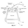
- FIG. 17is a simplified diagram of a vehicle for performing one or more tasks in the photovoltaic array according to one embodiment of the present invention.
- FIG. 18is a simplified diagram of a vehicle for performing one or more tasks in the photovoltaic array according to another embodiment of the present invention.
- the present inventionis directed to utility arrays. More particularly, the invention provides systems and methods for installation and operation of photovoltaic arrays. Merely by way of example, the invention has been applied to solar farms. But it would be recognized that the invention has a much broader range of applicability.
- FIG. 3is a simplified diagram showing a system for installation and operation of a photovoltaic array according to one embodiment of the present invention.
- the photovoltaic array 300is organized around one or more modular rails 310 (e.g. photovoltaic (PV) rails) oriented in a first direction.
- the photovoltaic array 300includes one or more photovoltaic modules.
- these modular rails 310are arranged in a general east-west orientation.
- each modular rail 310provides infrastructure for one or more module strings 320 (e.g. photovoltaic (PV) module strings) of one or more PV modules.
- PVphotovoltaic
- the modular rails 310are crossed by one or more index rails 330 that are substantially perpendicular to the modular rails 310 .
- the index rails 330are arranged in a second direction (e.g., a general north-south orientation).
- each of the modular rails 310has a substantially uniform profile along its length.
- each of the index rails 330has a substantially uniform profile along its length.
- the photovoltaic array 300includes one or more cables 340 (e.g. DC cables) that run in parallel along or perpendicularly to the modular rails 310 and/or the index rails 330 .
- the one or more cables 340are connected to a central inverter 350 , which is coupled to the power grid.
- each of the PV module strings 320employs a string inverter, and/or each of the PV modules within the same string employs a micro-inverter.
- the string inverter or the micro-inverteris used to convert the power generated at each string or module to AC power locally, without the need of the central inverter 350 .
- one or more vehicles 360are used to travel along the modular rails 310 and/or the index rails 330 .
- the one or more vehicles 360are used to aid in the installation of the photovoltaic array 300 .
- the one or more vehicles 360are used to provide logistics and maintenance support for the photovoltaic array 300 .
- the one or more vehicles 360are used for transporting materials.
- one or more vehicles 370e.g. index rail cars are used for transporting vehicles and/or materials along the index rails 330 .
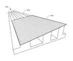
- FIG. 4is a simplified diagram showing the modular rail 310 for installation and operation of the photovoltaic array according to one embodiment of the present invention. This diagram is merely an example, which should not unduly limit the scope of the claims. One of ordinary skill in the art would recognize many variations, alternatives, and modifications.
- the modular rail 310includes one or more mounting surfaces 410 .
- the one or more mounting surfaces 410serve as the mechanical substrate for the mounting of one or more PV modules and/or one or more PV module strings.
- the mounting surfaces 410are substantially coplanar.
- FIG. 5is a simplified diagram showing the modular rail 310 that supports one or more PV modules according to one embodiment of the present invention. This diagram is merely an example, which should not unduly limit the scope of the claims. One of ordinary skill in the art would recognize many variations, alternatives, and modifications.
- a PV module 510is affixed to the one or more mounting surfaces 410 by using at least one or more mechanical connectors.
- a PV module 510is affixed directly to the one or more mounting surfaces 410 by using one or more adhesive materials.
- the one or more adhesive materialsinclude a glue.
- the one or more adhesive materialsinclude tape, paste, T5200, Silicone, epoxy, and/or Polyurethane foam.
- the PV module 510is not affixed directly to the one or more mounting surfaces 410 , but is affixed along with one or more flexible spacers using the one or more adhesive materials.
- the one or more mounting surfaces 410 of the modular rail 310are implemented with a tilt angle.
- the tilt anglevaries depending upon the geographic location (e.g. latitude or orientation) of the photovoltaic array so that the affixed PV module 510 is oriented for optimal energy capture from the light source (e.g., the Sun).
- the use of the one or more mounting surfaces 410provides certain advantages over conventional technology for the mounting of PV modules and PV module strings.
- the PV modules 510are fixed along their entire length to the one or more mounting surfaces 410 using glue or other adhesive materials.
- the PV modules 510do not have to be as strong as required by certain conventional technology.
- the adhesive mounting along the one or more surfaces 410provides a shorter span between the contact points of the PV modules 510 and the one or more mounting surfaces 410 ; therefore, the PV modules 510 are exposed to less mechanical stress due to wind loads than the PV modules mounted using conventional edge-mounted brackets.
- the PV modules 510can be made of thinner material than the conventional edge-mounted PV modules; therefore, the PV modules 510 can be manufactured and transported at lower cost due to their lighter weight.
- the PV modules 510benefit from the “heat sink” effect due to the proximity of the PV modules 510 to the modular rails 310 .
- the PV modules 510can stay slightly cooler than conventional modules and can operate more efficiently (e.g., due to the negative temperature coefficient).
- the use of flexible spacerscan provide the PV modules 510 with additional air cooling that can significantly reduce negative effects caused by the “heat sink” effect of the modular rails 310 .
- the modular rail 310also includes one or more plenums 420 for the placement of one or more cables.
- FIG. 6is a simplified diagram showing placement of one or more cables in one or more plenums of the modular rail 310 according to one embodiment of the present invention. This diagram is merely an example, which should not unduly limit the scope of the claims. One of ordinary skill in the art would recognize many variations, alternatives, and modifications.
- a cable 610is placed in a first cable plenum 620 and/or another cable 630 is placed in a second cable plenum 640 .
- the one or more cables 340include the cable 610 and/or the cable 630 .
- additional plenumscan be provided for additional cables.
- the central mounting surface 650is eliminated to form a single plenum in which the cable 610 and/or the cable 630 are placed together.
- the elimination of the central mounting surface 650results in reduced material costs for the modular rail 310 as well as a reduction in its overall weight.
- the cable plenum 620 and/or the cable plenum 640also has a cover that provides both mechanical and weather protection for the one or more cables.
- the modular rail 310is scribed, slotted, and/or notched at one or more intervals along its length to provide one or more plenums for the placement of one or more cables (e.g., the one or more cables 340 ) that are perpendicular to the modular rail 310 and/or for the drainage of water from the modular rail 310 .
- the one or more notchesare substantially perpendicular to the modular rail 310 .
- the cable 610 and/or the cable 630does not need to be placed in the plenum 620 and/or the plenum 640 , but could instead be placed separately from the modular rails 310 , for example, in underground trenches.
- the plenum 620 and/or the plenum 640provides space to accommodate the junction box of a PV module.
- the cable 610 and/or the cable 630serve to interconnect the various PV modules or PV module strings.
- the cablesare used to send the DC power generated by the PV modules or PV module strings to a central inverter 350 for conversion to AC power and transmission to the power grid.
- the cablesare factory pre-made with connectors that allow for easy field interconnections between the PV module strings and the central inverter 350 .
- the modular rail 310also includes one or more vehicle support surfaces 430 (e.g., tracks, rails or road beds).
- the one or more vehicle support surfaces 430allow a vehicle to move along the modular rail 310 .
- the vehicleis used to install PV modules and/or provide logistics, operational, and/or maintenance support for the photovoltaic array.
- the modular rail 310includes various positional indicators that are installed at intervals along its length.
- the positional indicatorsinclude, but not limited to, magnetic wires, RFID modules, and/or visual indicators that denote the location of the particular modular rail segment within the larger photovoltaic array.
- a vehicle that operates along the modular railincludes sensors for detecting these positional indicators so that the vehicle can detect its location within the photovoltaic array.
- the modular rail 310is optimized to reduce the amount of material needed per unit length.
- the thickness of a bottom portion 440 of the modular rail 310is optimized to reduce amount of material needed for a given surface roughness of a particular site.
- the modular rail 310is constructed from concrete.
- the modulation rail 310is constructed on site (e.g., being extruded in place using a slip-form extrusion machine).
- FIG. 4is merely an example, which should not unduly limit the scope of the claims.
- the bottom portion 440 of the modular rail 310has a bottom surface that forms one or more channels at one or more intervals along the length of the modular rail 310 .
- the one or more channelsare perpendicular to the modular rail 310 .
- the one or more channelsallow water to flow under the modular rail 310 .
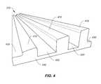
- FIG. 7is a simplified diagram showing the modular rail 310 for installation and operation of the photovoltaic array according to another embodiment of the present invention.
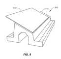
- FIG. 8is a simplified diagram showing the modular rail 310 that supports the one or more PV modules according to another embodiment of the present invention.
- the modular rail 310includes only a single mounting surface 710 for the PV module 510 or the PV module string according to one embodiment.
- the modular rail 310also includes a void 720 , which, for example, reduces the amount of material needed per unit length and/or reduces the overall weight and cost of the modular rail 310 .
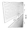
- FIG. 9is a simplified diagram showing the index rail 330 for installation and operation of the photovoltaic array according to one embodiment of the present invention. Additionally, FIG. 10 is a simplified diagram showing placement of one or more cables in one or more plenums of the index rail 330 according to one embodiment of the present invention. These diagrams are merely examples, which should not unduly limit the scope of the claims. One of ordinary skill in the art would recognize many variations, alternatives, and modifications.
- the index rail 330includes one or more plenums 910 .
- two adjacent plenums 910are separated by a divider 920 .
- the one or more plenums 910are used for the placement of one or more cables 1010 .
- the one or more cables 340include the one or more cables 1010 .
- the index rail 330is used to support movement between modular rails.
- the divider 920 of the index rail 330is eliminated so that one or more cables 1010 are placed in the same plenum of the index rail 330 .
- the one or more cables 1010are interconnected with the cable 610 and/or the cable 630 in order to, for example, collect the generated power at the central inverter 350 for transmission to the power grid.
- the one or more cable plenums 910also have one or more covers that provide both mechanical and weather protection for the one or more cables.
- the index rail 330is scribed, slotted, or notched at one or more intervals along its length to provide one or more plenums for the placement of one or more cables (e.g., the one or more cables 340 ) that are perpendicular to the index rail 330 and/or for the drainage of water from the index rail 330 .
- the one or more notchesare substantially perpendicular to the index rail 330 .
- the one or more cables 1010do not need to be placed in the one or more plenums 910 , but could instead be placed separately from the index rail 330 , for example, in underground trenches.
- the index rail 330also includes one or more vehicle support surfaces 930 (e.g., tracks, rails or road beds).
- the one or more vehicle support surfaces 930allow a vehicle to move along the index rail 330 .
- the vehicleis used to install PV modules and/or provide logistics, operational, and/or maintenance support for the photovoltaic array.
- the index rail 330includes various positional indicators that are installed at intervals along its length.
- the positional indicatorsinclude, but not limited to, magnetic wires, RFID modules, and/or visual indicators that denote the location of the particular index rail segment within the larger photovoltaic array.
- a vehicle that operates along the index railincludes sensors for detecting these positional indicators so that the vehicle can detect its location within the photovoltaic array.
- the index rail 330is optimized to reduce the amount of material needed per unit length.
- the thickness of a bottom portion 940 of the index rail 330is optimized to reduce amount of material needed for a given surface roughness of a particular site.
- the index rail 330is constructed from concrete.
- the index rail 330is constructed on site (e.g., being extruded in place using a slip-form extrusion machine).
- the bottom portion 940 of the index rail 330has a bottom surface that forms one or more channels at one or more intervals along the length of the index rail 330 .
- the one or more channelsare perpendicular to the index rail 330 .
- the one or more channelsallow water to flow under the index rail 330 .
- FIG. 11is a simplified diagram showing a method for constructing the photovoltaic array 300 according to one embodiment of the present invention. This diagram is merely an example, which should not unduly limit the scope of the claims. One of ordinary skill in the art would recognize many variations, alternatives, and modifications.
- the method 2100includes a process 2110 for building the one or more index rails 330 , a process 2120 for building the one or more modular rails 310 , a process 2130 for placing the one or more cables 340 , a process 2140 for mounting the one or more PV modules along the one or more modular rails 310 , a process 2150 for connecting the one or more PV modules, a process 2160 for installing the one or more inverters, a process 2170 for connecting the one or more inverters to the one or more PV modules, and a process 2180 for coupling the one or more inverters to the power grid.
- the process 2110 for building the one or more index rails 330 and/or the process 2120 for building the one or more modular rails 310can be performed with various methods.
- the installation siteis graded, to the extent necessary, where each of the one or more index rails 330 and/or the one or more modular rails 310 are to be placed.
- one or more “carpets” of reinforcing meshare rolled out where each rail is to be placed. These “carpets” are made of concrete iron rebar mesh and/or of other non-metal reinforcing meshes of materials such as polymers and/or glass fibers.
- a specialized machinee.g. a slip-form extrusion machine lays a continuous profile of concrete that makes up each rail according to one embodiment.
- the slip-form extrusion machineis used to create a customized profile.
- the uneven surface of the ground where each rail is castis naturally filled with concrete in between the reinforcing mesh to provide a stable rail track.
- the concrete railis scribed, slotted, and/or notched (e.g., before or after the concrete has cured) to ensure separation of the rail for thermal expansion and contraction to prevent cracking of the rail.
- the scribes, slots, and/or notchesalso serve as water drainage points along each rail to keep each cable plenum dry as well as to provide access points for the cable that connect to the ends of the PV module strings.
- the one or more index rails 330are placed substantially parallel to each other in a first direction according to one embodiment.
- this first directionis approximately north-south in orientation.
- the one or more index rails 330once they are in place, they provide a convenient mechanism for the transportation of materials and other equipment across the installation site by use of the vehicle support surfaces 930 of the index rails.
- the array of railsallows for movement around the array while avoiding the problems of ground water and mud.
- the one or more modular rails 310are placed substantially perpendicular to the one or more index rails 330 according to another embodiment.
- the one or more modular rails 310are placed in an approximately east-west orientation.
- the one or more cables 340are placed.
- the one or more cables 340are placed using one or more of the various plenums and scribes, slots, and/or notches.
- the one or more cables 340route the DC power generated by the PV modules to the central inverter 350 for conversion.
- the one or more PV modulesare mounted along the one or more modular rails 310 .
- the process 2140is performed by at least the one or more robotic arms 1640 .
- the installation process for the PV modulesincludes multiple operations that can be performed in various orders. In one embodiment, these multiple operations include affixing a PV module (e.g., a solar panel) to the one or more mounting surfaces of a modular rail 310 using at least one or more mechanical connectors and/or one or more adhesive materials.
- the one or more adhesive materialsinclude glue, tape, paste, T5200, Silicone, epoxies, and/or Polyurethane foam.
- one or more PV modulesare installed end-to-end along the modular rail 310 to form a PV module string 320 .
- the one or more PV modulesare connected.
- the one or more PV modulese.g., the PV module 510
- the one or more PV modulesare connected using one or more types of interconnectors (e.g., a rigid in-line slide-on interconnector, a flexible slide-in interconnector, a flexible ribbon interconnector, and/or an in-line slide-in edge interconnector).
- the one or more PV modulese.g., the PV module 510
- the one or more PV modulesare connected using one or more types of conventional interconnectors.
- one or more interconnectorsare used to provide electrical connections between the PV modules.
- the one or more interconnectorscan provide additional structural stability between the PV modules.
- the one or more interconnectorscan eliminate the conventional junction boxes. In yet another embodiment, the one or more interconnectors also reduce or eliminate the need for the extensive cabling often found in a conventional photovoltaic array. In yet another embodiment, the one or more interconnectors are used to connect individual PV modules into PV module strings. In yet a further embodiment, the one or more interconnectors are used to provide flexible interconnections between the PV modules in order to reduce the stresses caused by heating and cooling of the PV modules.
- the one or more invertersare installed, connected to the one or more PV modules, and coupled to the power grid according to certain embodiments.
- FIG. 12is a simplified diagram showing a PV-module interconnection apparatus used for installation and operation of the photovoltaic array 300 according to an embodiment of the present invention.
- This diagramis merely an example, which should not unduly limit the scope of the claims.
- One of ordinary skill in the artwould recognize many variations, alternatives, and modifications.
- a PV module 1110is connected to another PV module 1120 using a rigid in-line slide-on interconnector 1130 .
- the rigid in-line slide-on interconnector 1130includes a connector surface that mates with the flat contact areas of at least two PV modules 1110 and 1120 .
- the rigid in-line slide-on interconnector 1130is in contact with the front glass and/or the back glass of at least two PV modules 1110 and 1120 and is folded over the edge of the front glass and/or the back glass of the PV modules 1110 and 1120 .
- FIG. 13is a simplified diagram showing a PV module interconnection apparatus used for installation and operation of the photovoltaic array 300 according to another embodiment of the present invention.
- This diagramis merely an example, which should not unduly limit the scope of the claims.
- a PV module 1210is connected to another PV module 1220 using a flexible slide-on interconnector 1230 .
- the flexible slide-on interconnector 1230includes two separate connector surfaces, which mate with the flat contact areas of the PV modules 1210 and 1220 respectively.
- the flexible slide-on interconnector 1230is in contact with the front glass and/or the back glass of at least two PV modules 1210 and 1220 and is folded over the edge of the front glass and/or the back glass of the PV modules 1210 and 1220 .
- FIG. 14is a simplified diagram showing a PV module interconnection apparatus used for installation and operation of the photovoltaic array 300 according to yet another embodiment of the present invention.
- a PV module 1310is connected to another PV module using a flexible ribbon interconnector 1320 .
- the flexible ribbon interconnector 1320is integrated with at least two PV modules.
- the flexible ribbon interconnector 1320is partially inserted between the front glass and the back glass of the PV module 1310 and between the front glass and the back glass of another PV module.
- the flexible ribbon interconnector 1320allows factory preassembly (including pre-interconnection) of PV modules. After the preassembly, the PV modules can be folded on top of each other for storage and/or transportation according to some embodiments.
- FIGS. 15 and 16are simplified diagrams showing a PV module interconnection apparatus used for installation and operation of the photovoltaic array 300 according to yet another embodiment of the present invention. These diagrams are merely examples, which should not unduly limit the scope of the claims. One of ordinary skill in the art would recognize many variations, alternatives, and modifications.
- a PV module 1410is connected to another PV module 1420 using an in-line slide-in edge interconnector 1450 .
- the in-line slide-in edge interconnector 1450is mounted under two PV modules 1410 and 1420 .
- the in-line slide-in edge interconnector 1450allows for automatic installation.
- the in-line slide-in edge interconnector 1450can improve environmental and mechanical protection.
- the in-line slide-in edge interconnector 1450includes a male connector 1440 and a female connector 1430 .
- the male connector 1440 and the female connector 1430are mounted under two different PV modules 1420 and 1410 , respectively.
- the pin on the male connector 1440can slide in and out of the mating socket on the corresponding female connector 1430 .
- the in-line slide-in edge interconnector 1450allows for movement (e.g., due to thermal expansion) to take place between the PV modules 1410 and 1420 .
- in-line slide-in edge interconnectors 1450are pre-mounted onto multiple PV modules so that the multiple PV modules can be installed as a group to become a PV module string 320 .
- the in-line slide-in edge interconnectors 1450are mounted onto multiple PV modules during installation of the PV modules.
- FIG. 17is a simplified diagram of a vehicle for performing one or more tasks in the photovoltaic array 300 according to one embodiment of the present invention.
- a vehicle 1600includes one or more wheels 1610 , one or more power supplies 1620 , one or more cargo areas 1630 , one or more robotic arms 1640 , one or more tools 1650 , one or more devices 1660 for sensing, controlling, and/or communicating, one or more adhesive dispensing apparatuses 1670 , and one or more apparatuses 1680 for concrete surface preparation.
- the vehicle 1600can be operated along the one or more modular rails 310 and/or the one or more index rails 330 .
- the vehicle 1600is used as the vehicle 360 and/or the vehicle 370 .
- the vehicle 1600can perform one or more automated tasks and can have one or more features depending upon the particular embodiments.
- the vehicle 1600can use one or more vehicle support surfaces (e.g., the one or more vehicle support surfaces 430 and/or the one or more vehicle support surfaces 930 ).
- the vehicle 1600includes the one or more wheels 1610 that roll around on the one or more vehicle support surfaces.
- other forms of locomotioncan be used, for example continuous tracks and/or caterpillar treads may be used.
- the vehicle 1600can use various forms of propulsion for locomotion.
- one or more electrical motorsare used to drive one or more of the wheels and/or caterpillar treads.
- hydraulicscan be used to drive one or more of the wheels and/or caterpillar treads.
- an internal combustion enginecan be used to drive one or more of the wheels and/or caterpillar treads.
- the vehicle 1600can access one or more power sources to run its various systems.
- the vehicle 1600uses one or more batteries as the one or more power supplies 1620 .
- the vehicle 1600uses an internal combustion generator for generating power and/or recharging the one or more batteries.
- the vehicle 1600uses one or more PV modules for generating power and/or recharging the one or more batteries.
- the vehicle 1600is capable of recharging the one or more batteries using one or more dedicated charging stations located at one or more locations within the photovoltaic array 300 .
- the vehicle 1600uses other alternative fuel sources and generators.
- the vehicle 1600includes the one or more cargo areas 1630 for transporting materials and supplies throughout the photovoltaic array 300 .
- the one or more cargo areas 1630can be used to transport one or more PV modules to their points of installation.
- the one or more cargo areas 1630can be used to transport one or more replacement PV modules to one or more desired locations and then carry away one or more replaced PV modules.
- the one or more cargo areas 1630can be used to transport one or more cables, adhesive materials, connectors, and/or other supplies needed during the installation and operation of the photovoltaic array 300 .
- the vehicle 1600includes the one or more robotic arms 1640 and/or the one or more tools 1650 according to one embodiment.
- each of the one or more robotic arms 1640is equipped with a universal gripping attachment.
- each of the one or more robotic arms 1640is equipped with one or more specialized tools 1650 .
- the one or more specialized tools 1650includes a special glass-panel lifting tool for lifting and/or manipulating one or more glass PV modules.
- the one or more specialized tools 1650can be used to apply the one or more adhesive materials.
- the one or more specialized tools 1650can be used to place cables, install the one or more interconnectors (e.g., the interconnector 1130 , the interconnector 1230 , the interconnector 1320 , and/or the interconnector 1450 ) between the PV modules, transport materials and supplies throughout the photovoltaic array 300 , load and unload supplies, and/or any of many other tasks needed during installation and operation of the photovoltaic array 300 .
- the one or more interconnectorse.g., the interconnector 1130 , the interconnector 1230 , the interconnector 1320 , and/or the interconnector 1450
- the vehicle 1600includes the one or more devices 1660 for sensing, controlling, and/or communicating.
- the one or more devices 1660are used at least for sensing.
- the vehicle 1600is equipped with one or more sensors used to determine its location within the photovoltaic array 300 .
- the one or more sensorsinclude a sensor for global positioning system (GPS), a mechanical sensor, a wheel sensor, an optical sensor, an RFID sensor, and/or a magnetic sensor.
- the wheel sensoris used to keep track of the location of the vehicle 1600 along the modular rail 310 and/or the index rail 330 .
- the optical sensorrecognizes the edges of already installed PV modules.
- the optical sensoris used to recognize one or more fixed locations along the modular rail 310 and/or the index rail 330 .
- the RFID sensorrecognizes one or more fixed locations along the modular rail 310 and/or the index rail 330 and/or recognizes one or more selected PV modules.
- the magnetic sensorrecognizes one or more magnetic wires that are embedded into or affixed to the modular rail 310 and/or the index rail 330 .
- the one or more devices 1660are used at least for controlling.
- the vehicle 1600includes a computer system for coordinating one or more tasks that the vehicle 1600 performs.
- the vehicle 1600is in communication with a central or distributed computer system that coordinates one or more tasks of one or more vehicles 1600 that operate within the photovoltaic array 300 .
- the one or more devices 1660is used at least for communicating.
- the vehicle 1600communicates with one or more other vehicles within the photovoltaic array 300 to jointly coordinate performance of the one or more tasks.
- the vehicle 1600includes a wireless communications interface (e.g., a WiFi interface, a Bluetooth interface, and/or an RFID interface).
- the wireless communications interfaceallows the vehicle 1600 to communicate with the external world via a wireless transceiver that is coupled to the Internet.
- the vehicle 1600includes the one or more adhesive dispensing apparatuses 1670 , which are, for example, used to dispense and/or apply one or more adhesive materials (e.g., during the process 2140 ).
- the vehicle 1600includes the one or more apparatuses 1680 that are used to prepare (e.g., cleaning) concrete surfaces (e.g., the one or more mounting surfaces 410 and/or 710 ) during, for example, the process 2140 .
- FIG. 17is merely an example, which should not unduly limit the scope of the claims.
- one or more componentse.g., the one or more adhesive dispensing apparatuses 1670
- the vehicle 1600is used as an installation vehicle, a supply vehicle, and/or a maintenance vehicle.
- the vehicle 1600e.g., the vehicle 360
- FIG. 18is a simplified diagram of a vehicle for performing one or more tasks in the photovoltaic array 300 according to another embodiment of the present invention.
- a vehicle 1700includes one or more wheels 1730 , one or more power supplies 1740 , one or more devices 1750 for sensing, controlling, and/or communicating, one or more parking areas 1710 , and/or one or more ramps 1720 .
- the one or more wheels 1730 , the one or more power supplies 1740 , and the one or more devices 1750are the same as the one or more wheels 1610 , the one or more power supplies 1620 , and the one or more devices 1660 , respectively.
- the vehicle 1700can be operated along the one or more modular rails 310 and/or the one or more index rails 330 .
- the vehicle 1700is used as the vehicle 370 that carries one or more vehicles 360 .
- the vehicle 1700can perform one or more automated tasks and can have one or more features depending upon the particular embodiments (e.g., transporting construction material along the one or more index rails 330 ).
- the one or more parking areas 1710 and the one or more ramps 1720serve to transport one or more vehicles (e.g., the vehicle 360 and/or the vehicle 1600 ) between different modular rails 310 .
- the vehicle 1700is automated and pre-programmed to move to a selected modular rail 310 through a wireless communications interface (e.g., a WiFi interface, a Bluetooth interface, and/or an RFID interface).
- the vehicle 1700can also communicate with the one or more other vehicles (e.g., the vehicle 360 and/or the vehicle 1600 ) so that the vehicle 1700 can send commands to and/or receive commands from the one or more other vehicles as to which modular rail 310 the vehicle 1700 should move to.
- one or more vehiclescan be used to automate one or more tasks for the installation and operation of the photovoltaic array 300 .
- a general-purpose vehiclee.g., the vehicle 1600
- a specialized vehiclee.g., the vehicle 1600 and/or the vehicle 1700
- a vehiclee.g., the vehicle 1600 and/or the vehicle 1700
- the vehiclecan transport the one or more PV modules to one or more locations within the photovoltaic array 300 where the PV modules are to be installed.
- the vehiclecan apply the one or more adhesive materials and/or the one or more flexible spacers, which are used to affix the one or more PV modules to the one or more mounting surfaces of the one or more modular rails 330 (e.g., the one or more mounting surfaces 410 and/or the one or more mounting surfaces 710 ).
- the vehiclecan assemble and/or install the one or more interconnectors (e.g., the interconnector 1130 , the interconnector 1230 , the interconnector 1320 , and/or the interconnector 1450 ) between the PV modules.
- the vehiclecan place and interconnect the one or more cables 340 throughout the photovoltaic array 300 .
- a vehiclee.g., the vehicle 1600 and/or the vehicle 1700
- a vehicleis used to partially or fully automate one or more operational tasks of the photovoltaic array 300 , including without limitation one or more maintenance, diagnostics, material supply, and/or repair functions for the photovoltaic array 300 .
- the one or more maintenance functionsinclude vegetation control, snow removal, cleaning, mounting integrity assessment, and/or mobile illumination (e.g., for assessing performance of one or more selected photovoltaic modules).
- the vehicleincludes one or more robotic arms (e.g., the one or more robotic arms 1640 ) and/or one or more tools (e.g., the one or more tools 1650 ) to perform one or more tasks.
- the one or more tasksinclude cleaning of one or more PV modules to remove dirt and dust on the front glass, replacing one or more defective PV modules, and/or replacing one or more damaged or deteriorated interconnectors.
- the one or more tasksinclude communicating with one or more PV modules via a wireless communications interface (e.g., a WiFi interface, a Bluetooth interface, and/or an RFID interface) to determine the self-diagnostic status of the one or more PV modules, and/or lighting up individual panels of the PV modules at night and performing diagnostic tests as to their status and general health.
- the one or more tasksinclude asset tracking and/or removing ground vegetation that interferes with the PV modules (e.g., with a lawnmower-style accessory and/or with a chemical spray system).
- the photovoltaic array 300can bring benefits to certain conventional PV modules 210 that are not designed specifically for the photovoltaic array 300 if, for example, the junction boxes 220 on the conventional PV modules 210 do not interfere with the PV-module surfaces that are to be mounted onto one or more mounting surfaces, (e.g., the one or more mounting surfaces 410 and/or the mounting surface 710 ).
- the junction boxes 220 on the conventional PV modules 210are accessible after the PV modules 210 are affixed to the one or more modular rails 310 , automatic mounting and/or interconnection of the PV modules 210 by one or more vehicles (e.g., the one or more vehicles 1600 and/or the one or more vehicles 1700 ) can be performed.
- placing of the one or more cables 340 in one or more plenumscan be performed for the photovoltaic array 300 with certain conventional PV modules 210 .
- the periodic cleaning, vegetation control, and testing of certain conventional PV modules 210can be performed by one or more vehicles (e.g., the one or more vehicles 1600 and/or the one or more vehicles 1700 ) for the photovoltaic array 300 .
- the testing and asset tracking of certain conventional PV modules 210can be performed by one or more vehicles (e.g., the one or more vehicles 1600 and/or the one or more vehicles 1700 ), if, for example, one or more built-in smart RFID sensors are added to the conventional PV modules 210 .
- a rail system for a photovoltaic arrayincludes at least one modular rail in a first direction.
- the modular railincludes a first vehicle support surface along the first direction and a first mounting surface along the first direction.
- the first vehicle support surfaceis configured to support at least a first vehicle moving in the first direction
- the first mounting surfaceis configured to support one or more photovoltaic modules mounted on the first mounting surface.
- the systemis implemented according to at least FIG. 3 , FIG. 4 , and/or FIG. 7 .
- the modular railfurther includes a plenum along the first direction, the plenum being configured to hold one or more cables.
- the modular railfurther includes a cover for the plenum.
- the modular railfurther includes one or more notches at one or more intervals respectively along the modular rail, and the one or more notches are substantially perpendicular to the first direction.
- the modular railfurther includes a base surface opposite to the first mounting surface, and the first mounting surface is tilted relative to the base surface.
- the modular railfurther includes a base surface opposite to the first mounting surface. The base surface forms one or more channels at one or more intervals along the modular rail, and the one or more channels are substantially perpendicular to the first direction.
- the modular railfurther includes a second mounting surface along the first direction, and the second mounting surface is substantially coplanar with the first mounting surface.
- the modular railfurther includes one or more indicia at one or more intervals respectively along the modular rail, and the one or more indicia are configured to identify one or more locations in the rail system.
- the rail systemfurther includes a first photovoltaic module affixed to the first mounting surface with at least one or more mechanical connectors. In yet another example, the rail system further includes a first photovoltaic module affixed to the first mounting surface with at least one or more adhesive materials. In yet another example, the first photovoltaic module is affixed to the first mounting surface using at least a flexible spacer with at least the one or more adhesive materials. In yet another example, the rail system further includes a second photovoltaic module coupled to the first photovoltaic module through at least an interconnector. In yet another example, the interconnector is selected from a group consisting of a rigid in-line slide-on interconnector, a flexible slide-in interconnector, a flexible ribbon interconnector, and an in-line slide-in edge interconnector.
- the rail systemfurther includes the first vehicle configured to perform one or more first tasks.
- each of the one or more first tasksis associated with at least installation, operation, logistics, or servicing of a photovoltaic array.
- the first vehicleis further configured to perform the one or more first tasks automatically.
- the first vehicleincludes at least a power supply selected from a group consisting of a battery, a photovoltaic module, and a combustion engine.
- the first vehicleincludes at least a sensor configured to determine a location of the first vehicle.
- the modular railincludes one or more indicia at one or more intervals respectively along the modular rail, the one or more indicia are configured to identify one or more locations in the rail system, and the sensor is further configured to determine the location using the one or more indicia.
- the first vehicleincludes at least a communication system to communicate with a second vehicle, the second vehicle being configured to perform one or more second tasks.
- the second vehicleis further configured to transport the first vehicle.
- the rail systemfurther includes at least one index rail in a second direction.
- the index railincludes a second vehicle support surface along the second direction, and the second vehicle support surface is configured to support at least a second vehicle moving in the second direction.
- the second vehicle support surfaceis further configured to support at least the first vehicle moving in the second direction.
- the index railfurther includes a plenum along the second direction, the plenum being configured to hold one or more cables.
- the index railfurther includes a cover for the plenum.
- the index railfurther includes one or more notches at one or more intervals respectively along the index rail, and the one or more notches are substantially perpendicular to the second direction.
- the index railfurther includes a base surface forming one or more channels at one or more intervals along the index rail, and the one or more channels being substantially perpendicular to the second direction.
- the first direction and the second directionare substantially perpendicular.
- a method for making a photovoltaic railincludes grading an installation site, and extruding at least one photovoltaic rail associated with a substantially uniform profile along its length.
- the process for extruding at least one photovoltaic railincludes making at least a vehicle support surface along the photovoltaic rail.
- the methodis implemented according to at least FIG. 4 , FIG. 7 , and/or FIG. 9 .
- the methodfurther includes placing a reinforcing mesh on the installation site before the process for extruding at least one photovoltaic rail is performed.
- the process for extruding at least one photovoltaic railfurther includes making at least a mounting surface along the photovoltaic rail.
- the process for extruding at least one photovoltaic railfurther includes making at least a plenum along the photovoltaic rail.
- the methodfurther includes covering the plenum of the photovoltaic rail.
- the methodfurther includes making one or more notches at one or more intervals respectively along the photovoltaic rail, and the one or more notches are substantially perpendicular to the modular rail.
- the photovoltaic railis a modular rail or an index rail.
- a method for installing a photovoltaic arrayincludes forming at least one modular rail in a first direction.
- the modular railincludes a first vehicle support surface along the first direction and a mounting surface along the first direction.
- the methodincludes affixing at least a first photovoltaic module and a second photovoltaic module to the mounting surface, and interconnecting the first photovoltaic module to the second photovoltaic module.
- the process for affixing at least a first photovoltaic module and a second photovoltaic module to the mounting surfaceincludes moving a first vehicle along the first vehicle support surface, and the first vehicle includes at least one robotic arm.
- the process for affixing at least a first photovoltaic module and a second photovoltaic module to the mounting surfaceincludes affixing the first photovoltaic module and the second photovoltaic module to the mounting surface by at least the robotic arm.
- the methodis implemented according to at least FIG. 3 , FIG. 5 , FIG. 8 , and/or FIG. 11 .
- the methodfurther includes forming at least one index rail in a second direction, and the index rail includes a second vehicle support surface along the index rail.
- the methodfurther includes loading a first vehicle onto a second vehicle, and moving the second vehicle carrying the first vehicle.
- the process for affixing at least a first photovoltaic module and a second photovoltaic module to the mounting surfaceis performed with at least one or more adhesive materials.
- the process for affixing at least a first photovoltaic module and a second photovoltaic module to the mounting surfaceis performed with at least one or more mechanical connectors.
- the present inventionprovides advantages over conventional technology. Certain embodiments of the present invention provide a photovoltaic array based on at least one or more modular rails that enable partial or full automation of many installation and operational tasks. Some embodiments of the present invention can reduce time and cost of installation and operation of a photovoltaic array. For example, the maintenance and operation cost of the photovoltaic array is significantly reduced. In another example, the servicing of the photovoltaic array (e.g., diagnostics, cleaning, and/or snow removal) is significantly improved. Certain embodiments of the present invention provide one or more vehicles that can move along one or more modular rails and/or one or more index rails to navigate throughout the photovoltaic array and perform various tasks.
- Some embodiments of the present inventionprovide a photovoltaic array that does not need panel-to-panel cable strain relief. Certain embodiments of the present invention provide an installation method and system that eliminates expensive junction boxes and standardized cable interconnects of conventional PV modules. Some embodiments of the present invention can improve wind tolerance of a photovoltaic array.
Landscapes
- Engineering & Computer Science (AREA)
- Mechanical Engineering (AREA)
- Chemical & Material Sciences (AREA)
- Sustainable Development (AREA)
- Sustainable Energy (AREA)
- Thermal Sciences (AREA)
- Physics & Mathematics (AREA)
- Combustion & Propulsion (AREA)
- Life Sciences & Earth Sciences (AREA)
- General Engineering & Computer Science (AREA)
- Manufacturing & Machinery (AREA)
- Microelectronics & Electronic Packaging (AREA)
- Robotics (AREA)
- Photovoltaic Devices (AREA)
Abstract
Description
Claims (31)
Priority Applications (5)
| Application Number | Priority Date | Filing Date | Title |
|---|---|---|---|
| US13/091,960US9462734B2 (en) | 2010-04-27 | 2011-04-21 | Rail systems and methods for installation and operation of photovoltaic arrays |
| US14/050,237US9655292B2 (en) | 2010-04-27 | 2013-10-09 | Methods of making photovoltaic arrays and rail systems |
| US14/919,185US20160044843A1 (en) | 2010-04-27 | 2015-10-21 | Rail systems and methods for installation and operation of photovoltaic arrays |
| US15/244,880US20170047885A1 (en) | 2010-04-27 | 2016-08-23 | Rail systems and methods for installation and operation of photovoltaic arrays |
| US15/343,043US20170054407A1 (en) | 2010-04-27 | 2016-11-03 | Rail systems and methods for installation and operation of photovoltaic arrays |
Applications Claiming Priority (2)
| Application Number | Priority Date | Filing Date | Title |
|---|---|---|---|
| US32857510P | 2010-04-27 | 2010-04-27 | |
| US13/091,960US9462734B2 (en) | 2010-04-27 | 2011-04-21 | Rail systems and methods for installation and operation of photovoltaic arrays |
Related Parent Applications (1)
| Application Number | Title | Priority Date | Filing Date |
|---|---|---|---|
| US32857510PContinuation | 2010-04-27 | 2010-04-27 |
Related Child Applications (2)
| Application Number | Title | Priority Date | Filing Date |
|---|---|---|---|
| US14/050,237DivisionUS9655292B2 (en) | 2010-04-27 | 2013-10-09 | Methods of making photovoltaic arrays and rail systems |
| US15/244,880ContinuationUS20170047885A1 (en) | 2010-04-27 | 2016-08-23 | Rail systems and methods for installation and operation of photovoltaic arrays |
Publications (2)
| Publication Number | Publication Date |
|---|---|
| US20110284057A1 US20110284057A1 (en) | 2011-11-24 |
| US9462734B2true US9462734B2 (en) | 2016-10-04 |
Family
ID=44861879
Family Applications (5)
| Application Number | Title | Priority Date | Filing Date |
|---|---|---|---|
| US13/091,960Expired - Fee RelatedUS9462734B2 (en) | 2010-04-27 | 2011-04-21 | Rail systems and methods for installation and operation of photovoltaic arrays |
| US14/050,237Expired - Fee RelatedUS9655292B2 (en) | 2010-04-27 | 2013-10-09 | Methods of making photovoltaic arrays and rail systems |
| US14/919,185AbandonedUS20160044843A1 (en) | 2010-04-27 | 2015-10-21 | Rail systems and methods for installation and operation of photovoltaic arrays |
| US15/244,880AbandonedUS20170047885A1 (en) | 2010-04-27 | 2016-08-23 | Rail systems and methods for installation and operation of photovoltaic arrays |
| US15/343,043AbandonedUS20170054407A1 (en) | 2010-04-27 | 2016-11-03 | Rail systems and methods for installation and operation of photovoltaic arrays |
Family Applications After (4)
| Application Number | Title | Priority Date | Filing Date |
|---|---|---|---|
| US14/050,237Expired - Fee RelatedUS9655292B2 (en) | 2010-04-27 | 2013-10-09 | Methods of making photovoltaic arrays and rail systems |
| US14/919,185AbandonedUS20160044843A1 (en) | 2010-04-27 | 2015-10-21 | Rail systems and methods for installation and operation of photovoltaic arrays |
| US15/244,880AbandonedUS20170047885A1 (en) | 2010-04-27 | 2016-08-23 | Rail systems and methods for installation and operation of photovoltaic arrays |
| US15/343,043AbandonedUS20170054407A1 (en) | 2010-04-27 | 2016-11-03 | Rail systems and methods for installation and operation of photovoltaic arrays |
Country Status (3)
| Country | Link |
|---|---|
| US (5) | US9462734B2 (en) |
| EP (1) | EP2564426A1 (en) |
| WO (1) | WO2011137050A1 (en) |
Cited By (8)
| Publication number | Priority date | Publication date | Assignee | Title |
|---|---|---|---|---|
| US9641123B2 (en) | 2011-03-18 | 2017-05-02 | Alion Energy, Inc. | Systems for mounting photovoltaic modules |
| US9937846B2 (en) | 2013-09-11 | 2018-04-10 | Alion Energy, Inc. | Vehicles and methods for magnetically managing legs of rail-based photovoltaic modules during installation |
| US9988776B2 (en) | 2015-09-11 | 2018-06-05 | Alion Energy, Inc. | Wind screens for photovoltaic arrays and methods thereof |
| US10122319B2 (en) | 2013-09-05 | 2018-11-06 | Alion Energy, Inc. | Systems, vehicles, and methods for maintaining rail-based arrays of photovoltaic modules |
| US10367443B2 (en)* | 2016-07-08 | 2019-07-30 | Alion Energy, Inc. | Systems and methods for supporting solar panels |
| US11050383B2 (en) | 2019-05-21 | 2021-06-29 | Nextracker Inc | Radial cam helix with 0 degree stow for solar tracker |
| US11159120B2 (en) | 2018-03-23 | 2021-10-26 | Nextracker Inc. | Multiple actuator system for solar tracker |
| US11387771B2 (en) | 2018-06-07 | 2022-07-12 | Nextracker Llc | Helical actuator system for solar tracker |
Families Citing this family (28)
| Publication number | Priority date | Publication date | Assignee | Title |
|---|---|---|---|---|
| US11063553B2 (en) | 2008-11-17 | 2021-07-13 | Kbfx Llc | Solar carports, solar-tracking carports, and methods |
| US20140041321A1 (en)* | 2008-11-17 | 2014-02-13 | Alain Poivet | Building Systems |
| US10277159B2 (en) | 2008-11-17 | 2019-04-30 | Kbfx Llc | Finished multi-sensor units |
| US9462734B2 (en) | 2010-04-27 | 2016-10-04 | Alion Energy, Inc. | Rail systems and methods for installation and operation of photovoltaic arrays |
| US9343592B2 (en) | 2010-08-03 | 2016-05-17 | Alion Energy, Inc. | Electrical interconnects for photovoltaic modules and methods thereof |
| US9020636B2 (en)* | 2010-12-16 | 2015-04-28 | Saied Tadayon | Robot for solar farms |
| US9494341B2 (en)* | 2011-05-27 | 2016-11-15 | Solarcity Corporation | Solar tracking system employing multiple mobile robots |
| CN103917832A (en)* | 2011-07-19 | 2014-07-09 | 布瑞特摩尔集团公司 | Mounting system for photovoltaic modules |
| USD744667S1 (en)* | 2011-12-19 | 2015-12-01 | Exterior Wall Systems Ltd. | Panel attachment extrusion with key |
| US9352941B2 (en) | 2012-03-20 | 2016-05-31 | Alion Energy, Inc. | Gantry crane vehicles and methods for photovoltaic arrays |
| RU2014150870A (en) | 2012-05-16 | 2016-07-10 | Эйлион Энерджи, Инк. | ROTARY SUPPORT SYSTEMS FOR PHOTOELECTRIC MODULES AND RELATED METHODS |
| US9515599B2 (en)* | 2013-09-17 | 2016-12-06 | Lumos Lsx, Llc | Photovoltaic panel mounting rail with integrated electronics |
| US9718334B2 (en) | 2015-04-09 | 2017-08-01 | Kevin Paul Means | Assembly and method for supporting and locking movable solar panels |
| US10148216B2 (en) | 2015-06-11 | 2018-12-04 | Darfon Electronics Corp. | Package of a supporting device for photovoltaic panels and kit for forming a supporting device for at least one photovoltaic panel |
| WO2017091471A1 (en)* | 2015-11-25 | 2017-06-01 | Alion Energy, Inc. | Systems, vehicles, and methods for maintaining rail-based arrays of photovoltaic modules |
| US12294332B2 (en) | 2015-12-15 | 2025-05-06 | Kbfx Llc | Solar carports, solar-tracking carports, and methods |
| KR102750796B1 (en)* | 2015-12-16 | 2025-01-08 | 파이브비 아이피 홀딩스 피티와이 엘티디 | Mobile solar power array |
| JP2019507759A (en) | 2016-03-09 | 2019-03-22 | ロサンゼルス バイオメディカル リサーチ インスティテュート アット ハーバー− ユーシーエルエー メディカル センター | Methods and kits for use in the prevention and treatment of vulvovaginal candidiasis |
| KR20190008846A (en)* | 2016-03-18 | 2019-01-25 | 인텔리-프로덕츠 인코포레이티드 | Advanced Solar PV System with Robot Assembly |
| US11241799B2 (en)* | 2016-03-18 | 2022-02-08 | Intelli-Products Inc. | Solar energy array robotic assembly |
| US10571274B2 (en)* | 2016-07-08 | 2020-02-25 | Alion Energy, Inc. | Systems, methods, and vehicles for maintaining solar panels |
| WO2018009650A1 (en)* | 2016-07-08 | 2018-01-11 | Alion Energy, Inc. | Systems, methods, and vehicles for maintaining solar panels |
| US11228275B2 (en) | 2019-06-27 | 2022-01-18 | National Oilwell Vareo, L.P. | Methods and apparatus for installing solar panels |
| CN110281253B (en)* | 2019-07-17 | 2020-12-15 | 中民新能投资集团有限公司 | Photovoltaic power station cleaning robot control box and automatic protection method |
| WO2021188874A1 (en) | 2020-03-20 | 2021-09-23 | Rosendin Electric, Inc. | A robotic arm cooperating with an off-road capable base vehicle |
| US12334868B2 (en) | 2020-08-28 | 2025-06-17 | The Aes Corporation | Solar panel handling system |
| US12184231B2 (en) | 2020-08-28 | 2024-12-31 | The Aes Corporation | Solar panel handling system |
| US11833677B2 (en) | 2022-04-20 | 2023-12-05 | Inventus Holdings Llc | Semi-autonomous exoskeleton apparatus for solar panel installation |
Citations (163)
| Publication number | Priority date | Publication date | Assignee | Title |
|---|---|---|---|---|
| US3334217A (en) | 1962-04-12 | 1967-08-01 | Hoffman Electronics Corp | Simulation of solar radiation |
| US3951506A (en) | 1975-04-24 | 1976-04-20 | The Bendix Corporation | Fail-safe connector |
| US4145021A (en) | 1976-08-11 | 1979-03-20 | Agence Nationale De Valorisation De La Recherche (Anvar) | Altazimuth orientation support |
| US4219926A (en) | 1979-02-23 | 1980-09-02 | Nasa | Method and apparatus for fabricating improved solar cell modules |
| US4279347A (en) | 1979-09-12 | 1981-07-21 | Rpc Corporation | Anti-sway load handling apparatus |
| US4290416A (en) | 1978-09-13 | 1981-09-22 | One Design, Inc. | Phase change energy storage panel for environmentally driven heating and cooling system |
| US4296270A (en) | 1979-05-11 | 1981-10-20 | Messerschmitt-Bolkow-Blohm Gmbh | Array of solar cells |
| US4301322A (en) | 1980-04-03 | 1981-11-17 | Exxon Research & Engineering Co. | Solar cell with corrugated bus |
| US4301409A (en) | 1978-06-06 | 1981-11-17 | California Institute Of Technology | Solar cell anomaly detection method and apparatus |
| US4371139A (en) | 1979-12-31 | 1983-02-01 | Sunsearch, Inc. | Adjustable mounting rack for solar collectors |
| US4421943A (en) | 1982-02-19 | 1983-12-20 | Cities Service Company | Collapsible mobile solar energy power source |
| US4496063A (en) | 1981-10-27 | 1985-01-29 | Kawasaki Steel Corporation | Method of handling slabs by an overhead traveling crane provided with a slab grip lifter |
| US4664270A (en) | 1983-10-07 | 1987-05-12 | Renner Manufacturing Company | Air transportable gantry type crane |
| US4667834A (en) | 1985-06-21 | 1987-05-26 | Mi-Jack Products, Inc. | Crane apparatus having hydraulic control system |
| US4676713A (en) | 1985-12-06 | 1987-06-30 | Voelpel Charles E | Material handling machine |
| US4706825A (en) | 1985-05-22 | 1987-11-17 | Harsco Corporation | Portable folding bridge crane |
| US4876143A (en) | 1985-07-05 | 1989-10-24 | Shimizu Construction Co., Ltd. | Rod material |
| US4877365A (en) | 1986-10-20 | 1989-10-31 | Mi-Jack Products Inc. | Side shift grappler |
| US4880346A (en) | 1987-10-16 | 1989-11-14 | Brassette Duane J | Self-loading truck and tilt bed therefor |
| US4995377A (en) | 1990-06-29 | 1991-02-26 | Eiden Glenn E | Dual axis solar collector assembly |
| US5125608A (en) | 1989-04-25 | 1992-06-30 | 700 Solar Club, Inc. | Photovoltaic panel support assembly |
| US5143556A (en) | 1989-03-13 | 1992-09-01 | Matlin Ronald W | Support for photovoltaic arrays |
| US5152109A (en) | 1990-10-11 | 1992-10-06 | Wenger Corporation | Portable performance platform |
| USD335541S (en) | 1991-01-08 | 1993-05-11 | Commonwealth Of Puerto Rico | Carport |
| US5228924A (en) | 1991-11-04 | 1993-07-20 | Mobil Solar Energy Corporation | Photovoltaic panel support assembly |
| US5232519A (en)* | 1990-09-20 | 1993-08-03 | United Solar Systems Corporation | Wireless monolithic photovoltaic module |
| US5257891A (en) | 1991-02-19 | 1993-11-02 | Mi-Jack Products, Inc. | Bi-planar cable cross reeving system |
| US5361704A (en) | 1989-03-30 | 1994-11-08 | Herzog Contracting Corp. | Railroad track laying system with multiple railroad tie handling |
| US5460660A (en) | 1993-07-21 | 1995-10-24 | Photon Energy, Inc. | Apparatus for encapsulating a photovoltaic module |
| US5501744A (en) | 1992-01-13 | 1996-03-26 | Photon Energy, Inc. | Photovoltaic cell having a p-type polycrystalline layer with large crystals |
| US5505788A (en)* | 1994-06-29 | 1996-04-09 | Dinwoodie; Thomas L. | Thermally regulated photovoltaic roofing assembly |
| US5568713A (en) | 1996-01-24 | 1996-10-29 | The Stanley Works | Mirror door and method of making same |
| US5593901A (en) | 1989-09-08 | 1997-01-14 | Amoco/Enron Solar | Monolithic series and parallel connected photovoltaic module |
| US5715958A (en) | 1995-01-24 | 1998-02-10 | Marine Travelift, Inc. | Stabilizer for a gantry crane lift frame |
| US5800631A (en) | 1995-08-24 | 1998-09-01 | Canon Kabushiki Kaisha | Solar cell module having a specific back side covering material and a process for the production of said solar cell module |
| US5816769A (en) | 1995-11-07 | 1998-10-06 | Siemens Aktiengesellschaft | Flexible manipulator |
| US5826734A (en) | 1996-10-09 | 1998-10-27 | Mi-Jack Products, Inc. | Variable elevating cabin |
| US6037578A (en) | 1997-07-15 | 2000-03-14 | Em Microelectronic-Marin Sa | Integrated photosensor using test capacitor to test functioning of photosensor in the dark |
| US6046399A (en) | 1997-01-13 | 2000-04-04 | Kapner; Mark | Roofing panels with integral brackets for accepting inclined solar panels |
| US6058930A (en) | 1999-04-21 | 2000-05-09 | Shingleton; Jefferson | Solar collector and tracker arrangement |
| US6111189A (en)* | 1998-07-28 | 2000-08-29 | Bp Solarex | Photovoltaic module framing system with integral electrical raceways |
| US6201181B1 (en) | 1998-12-08 | 2001-03-13 | Ase Americas, Inc. | Portable solar module cart |
| US6233502B1 (en)* | 1998-10-16 | 2001-05-15 | Xerox Corporation | Fault tolerant connection system for transiently connectable modular elements |
| US6495750B1 (en) | 2001-07-10 | 2002-12-17 | Powerlight Corporation | Stabilized PV system |
| US20030075211A1 (en)* | 2001-08-30 | 2003-04-24 | Hidehisa Makita | Photovoltaic power generation system |
| US6590363B2 (en) | 2001-05-16 | 2003-07-08 | Nissan Motor Co., Ltd. | Charging station |
| US6639421B1 (en) | 1997-06-30 | 2003-10-28 | Canon Kabushiki Kaisha | Measuring apparatus and method for measuring characteristic of solar cell |
| US6722357B2 (en) | 2001-08-15 | 2004-04-20 | Powerlight Corporation | Fixed angle solar collector arrangement |
| US6730841B2 (en) | 2001-03-14 | 2004-05-04 | United Solar Systems Corporation | Method and apparatus for mounting a photovoltaic roofing material |
| US6809251B2 (en) | 2001-07-10 | 2004-10-26 | Powerlight Corporation | Inclined photovoltaic assembly |
| US20040250491A1 (en) | 2001-10-29 | 2004-12-16 | Diaz Emilio Mera | Low ballast mounting system |
| US20050061360A1 (en) | 2001-10-12 | 2005-03-24 | Tatsuji Horioka | Photovoltaic solar cell module assembly, wiring system and photovoltaic power system |
| US20050268959A1 (en) | 2004-06-04 | 2005-12-08 | Sunpower Corporation | Interconnection of solar cells in a solar cell module |
| US20060054162A1 (en) | 2004-09-03 | 2006-03-16 | Romeo Manuel L | Solar tracker |
| US7086675B2 (en) | 2003-12-08 | 2006-08-08 | Goudsmit Magnetic Systems Bv | Magnetic vacuum gripper including inflatable bellows |
| US20060174931A1 (en)* | 2001-11-16 | 2006-08-10 | First Solar, Llc A Delaware Corporation | Photovoltaic array |
| US20060290344A1 (en) | 2005-06-17 | 2006-12-28 | Mitsuhiro Shimotomai | Measurement method using solar simulator |
| US20070012352A1 (en) | 2005-07-18 | 2007-01-18 | Bp Corporation North America Inc. | Photovoltaic Modules Having Improved Back Sheet |
| WO2006117551A3 (en) | 2005-05-04 | 2007-02-22 | Lontra Environmental Technolog | Energy generating device and method |
| US7252083B2 (en) | 2005-07-18 | 2007-08-07 | Arizona Public Service Company | Structure for supporting energy conversion modules and solar energy collection system |
| US20070283996A1 (en) | 2006-06-13 | 2007-12-13 | Miasole | Photovoltaic module with insulating interconnect carrier |
| US7309850B2 (en) | 2005-08-05 | 2007-12-18 | Sinton Consulting, Inc. | Measurement of current-voltage characteristic curves of solar cells and solar modules |
| US20080010915A1 (en)* | 2001-07-20 | 2008-01-17 | Unirac, Inc | Apparatus and method for positioning a module on an object |
| US20080023069A1 (en) | 2006-07-28 | 2008-01-31 | Sanyo Electric Co., Ltd. | Photovoltaic element and fabrication method thereof |
| US20080040990A1 (en) | 2006-06-29 | 2008-02-21 | Herb Vendig | Seasonally Adjustable Mounting System for Solar Panels |
| US20080053517A1 (en) | 2006-08-31 | 2008-03-06 | Joshua Reed Plaisted | Technique for electrically bonding solar modules and mounting assemblies |
| US20080099063A1 (en) | 2006-10-23 | 2008-05-01 | Ascent Solar Technologies, Inc. | Flexible High-Voltage Adaptable Current Photovoltaic Modules And Associated Methods |
| US7374137B2 (en) | 2006-01-04 | 2008-05-20 | Wayne Staney | Directional support structure |
| US20080121273A1 (en) | 2006-11-29 | 2008-05-29 | Joshua Reed Plaisted | Mounting assembly for arrays and other surface-mounted equipment |
| US20080135084A1 (en) | 2006-12-11 | 2008-06-12 | Scharlack Ronald S | Sub-module photovoltaic control system |
| US20080156365A1 (en) | 2006-10-25 | 2008-07-03 | Scholz Jeremy H | Edge mountable electrical connection assembly |
| US20080233429A1 (en) | 2003-12-12 | 2008-09-25 | Sumitomo Chemical Company, Limited | Polymer Compound and Polymer Light-Emitting Device Using the Same |
| US20080271774A1 (en) | 2007-05-01 | 2008-11-06 | Kalkanoglu Husnu M | Photovoltaic Roofing Wiring Array, Photovoltaic Roofing Wiring System and Roofs Using Them |
| US20080306700A1 (en) | 2007-06-07 | 2008-12-11 | Ekla-Tek L.L.C | Photvoltaic solar array health monitor |
| US20090014057A1 (en) | 2007-07-13 | 2009-01-15 | Miasole | Photovoltaic modules with integrated devices |
| US20090032100A1 (en) | 2007-08-02 | 2009-02-05 | Eugene Oak | Position adjustable awning equipped with solar cell plates thereon |
| US7492120B2 (en) | 2001-04-06 | 2009-02-17 | Benn William M | Mobile solar generator |
| US20090114261A1 (en) | 2007-08-29 | 2009-05-07 | Robert Stancel | Edge Mountable Electrical Connection Assembly |
| US7531741B1 (en) | 2003-03-07 | 2009-05-12 | Sacred Power Corporation | Tracking solar shelter |
| US20090139557A1 (en) | 2007-11-30 | 2009-06-04 | Douglas Rose | Busbar connection configuration to accommodate for cell misalignment |
| US7546929B2 (en) | 2005-10-31 | 2009-06-16 | Marine Travelift, Inc. | Powered auxiliary hoist mechanism for a gantry crane |
| US20090173831A1 (en)* | 2005-05-13 | 2009-07-09 | Paul Roseman | Method for manufacturing a solar module in orbit |
| US20090191030A1 (en) | 2006-09-19 | 2009-07-30 | Intevac, Inc. | Apparatus and methods for transporting and processing substrates |
| US20090205270A1 (en)* | 2008-02-19 | 2009-08-20 | Shaw Wayne E | Structured Photovoltaic Roofing Elements, Systems and Kits |
| US20090223142A1 (en) | 2003-03-10 | 2009-09-10 | Sunpower Corporation, Systems | Modular Shade System with Solar Tracking Panels |
| US20090260671A1 (en) | 2007-12-13 | 2009-10-22 | First Solar, Inc. | Systems and methods of parallel interconnection of photovoltaic modules |
| US20090282755A1 (en) | 2008-05-19 | 2009-11-19 | Powermount Systems, Inc. | Photovoltaic mounting system with locking connectors, adjustable rail height and hinge lock |
| US20090293941A1 (en) | 2008-06-02 | 2009-12-03 | Daniel Luch | Photovoltaic power farm structure and installation |
| US20090293932A1 (en)* | 2008-06-03 | 2009-12-03 | Augenbraun Joseph E | Mounting System for Weatherproof Surfaces |
| US20090308430A1 (en) | 2005-06-17 | 2009-12-17 | The Australian National University | Solar Cell Interconnection Process |
| US20100031996A1 (en) | 2008-08-11 | 2010-02-11 | Basol Bulent M | Structure and method of manufacturing thin film photovoltaic modules |
| US20100043781A1 (en) | 2008-08-21 | 2010-02-25 | Jeremy Jones | Solar panel support module and method of creating array of interchangeable and substitutable solar panel support modules |
| US20100108118A1 (en)* | 2008-06-02 | 2010-05-06 | Daniel Luch | Photovoltaic power farm structure and installation |
| US7712807B2 (en) | 2004-02-04 | 2010-05-11 | Delaware Capital Formation, Inc. | Vacuum cup with relief port and method of moving and releasing an object |
| WO2010054274A2 (en) | 2008-11-06 | 2010-05-14 | Robert Stancel | Tensioned mounting of solar panels |
| US20100127142A1 (en) | 2007-04-23 | 2010-05-27 | Haticon Gmbh | Device for mounting solar modules |
| US20100147286A1 (en) | 2008-12-04 | 2010-06-17 | Xiao Dong Xiang | Systems and methods including features of synchronized movement across and array of solar collectors |
| US20100175738A1 (en) | 2007-04-15 | 2010-07-15 | Brightsource Industries (Israel) Ltd. | Heliostat and system |
| US20100175337A1 (en) | 2009-01-13 | 2010-07-15 | Optisolar Inc. | Flexible roof-mount system and method for solar panels |
| US20100206294A1 (en) | 2009-02-13 | 2010-08-19 | Jason Blair | Heliostat field cleaning system |
| US7799987B1 (en) | 2007-07-30 | 2010-09-21 | Hines Stephen P | Solar tracker |
| US20100252092A1 (en) | 2009-04-01 | 2010-10-07 | Sunpower Corp. | Photovoltaic array with minimally penetrating rooftop support system |
| CN101858659A (en) | 2008-12-04 | 2010-10-13 | 益科博能源科技(上海)有限公司 | Polar axis tracking device of solar collector |
| US7814899B1 (en) | 2006-07-04 | 2010-10-19 | Jonathan Port | Solar panel mounting systems |
| US20100269888A1 (en) | 2009-04-27 | 2010-10-28 | Johnston Jr Robert G | System for mounting and selectable adjustment of angle of elevation of groups of PV panels |
| US20100269429A1 (en) | 2009-03-11 | 2010-10-28 | Belikoff Michael A | Rooftop Photovoltaic Module Mounting System |
| US20100275975A1 (en) | 2009-04-30 | 2010-11-04 | Jonathan Monschke | Solar panel systems |
| US20100281791A1 (en) | 2009-05-11 | 2010-11-11 | Intagliata John D | Removable post and method for the assembly and use thereof |
| WO2010145844A2 (en) | 2009-06-19 | 2010-12-23 | Gehrlicher Solar Ag | Device for handling and positioning large-sized solar modules |
| US20100319277A1 (en) | 2009-06-19 | 2010-12-23 | Unirac, Inc. | Modular structural framing system |
| US20100325797A1 (en) | 2007-11-27 | 2010-12-30 | Mountain Angler Pty Ltd | Height adjustable support assembly |
| US7888588B2 (en) | 2003-03-18 | 2011-02-15 | Sunpower Corporation, Systems | Tracking solar collector assembly |
| DE102009049926A1 (en) | 2009-10-19 | 2011-04-28 | Siegfried Riebsamen | Fitting vehicle for provision and installation of e.g. glass panels, has handling device supplied with energy by drive, and multi axis rotating head provided with tool holder in handling device |
| US20110126884A1 (en) | 2008-06-02 | 2011-06-02 | Vasileios Dritsas | Photovoltaic panel support base rotating simultaneously around a horizontal and a vertical axis |
| US20110126378A1 (en) | 2008-09-04 | 2011-06-02 | Kawasaki Jukogyo Kabushiki Kaisha | Cleaning device for sunlight collecting devices in a solar thermal electric power generation system |
| US7963578B2 (en) | 2008-05-30 | 2011-06-21 | GM Global Technology Operations LLC | Integrated vacuum gripper with internal releasable magnet and method of using same |
| US20110162691A1 (en) | 2011-01-21 | 2011-07-07 | John Hartelius | Photovoltaic module support system |
| US20110183540A1 (en) | 2008-05-05 | 2011-07-28 | Dow Global Technologies Inc. | Connector device for building integrated photovoltaic device |
| US20110194900A1 (en) | 2010-02-10 | 2011-08-11 | French Sr William L | Segmented ballast base support structure and rail and trolley structures for unstable ground |
| US8006624B2 (en) | 2008-06-10 | 2011-08-30 | Tecsa Empresa Constructora, S.A. | Machine for unloading and positioning rails on crossties in railway tracks |
| CN202019322U (en) | 2011-03-04 | 2011-10-26 | 上海太阳能科技有限公司 | Photovoltaic uniaxial tracking bracket |
| US20110264306A1 (en) | 2008-10-17 | 2011-10-27 | Niels Henrik Bagge | Lifting Vehicle |
| FR2959555A1 (en) | 2010-04-30 | 2011-11-04 | Schneider Electric Ind Sas | CARRIER STRUCTURE MODULE FOR PHOTOVOLTAIC PANELS, CARRIER STRUCTURE COMPRISING SUCH MODULES AND METHOD FOR MOUNTING SUCH A STRUCTURE. |
| US20110309215A1 (en) | 2010-06-21 | 2011-12-22 | Hon Hai Precision Industry Co., Ltd. | Support assembly for photovoltaic panels |
| WO2012003585A1 (en) | 2010-07-05 | 2012-01-12 | George Gregory Lessard | Solar panel deployment system |
| US20120027550A1 (en) | 2010-07-29 | 2012-02-02 | John Bellacicco | Automated installation system for and method of deployment of photovoltaic solar panels |
| US20120034799A1 (en) | 2010-08-03 | 2012-02-09 | Alion, Inc. | Electrical interconnects for photovoltaic modules and methods thereof |
| US20120037214A1 (en) | 2009-04-08 | 2012-02-16 | Kenichi Sagayama | Solar cell module, solar cell attachment stand, photovoltaic power generating system |
| US20120056638A1 (en) | 2010-03-10 | 2012-03-08 | Alion, Inc. | Systems and methods for monitoring and diagnostics of photovoltaic solar modules in photovoltaic systems |
| US20120067738A1 (en) | 2006-02-10 | 2012-03-22 | Tennant Company | Mobile Surface Cleaner and Method for Generating and Applying an Electrochemically Activated Sanitizing Liquid Having O3 Molecules |
| US20120132262A1 (en) | 2009-08-07 | 2012-05-31 | Kenichi Sagayama | Structure installation rack, method for installing the same, structure connecting structure, connection member and method for installing this structure connecting structure, and solar cell system |
| US20120132246A1 (en) | 2010-05-27 | 2012-05-31 | Alion, Inc. | Photovoltaic modules with improved electrical characteristics and methods thereof |
| US20120131866A1 (en) | 2009-05-26 | 2012-05-31 | Bernard Batut | Parking shelter provided with photovoltaic solar panels |
| US8203237B1 (en) | 2009-01-15 | 2012-06-19 | Cowles Scott R | Portable power generating unit |
| US20120198682A1 (en) | 2011-02-08 | 2012-08-09 | Chevron Usa Inc. | Edge conveyor belt solar string assembly device |
| US20120199266A1 (en) | 2011-02-08 | 2012-08-09 | Chevron Usa Inc. | Robotic solar panel string assembly process |
| US20120198779A1 (en) | 2011-02-04 | 2012-08-09 | Tachino Takashi | Solar panel mounting structure |
| US20120223033A1 (en) | 2009-11-12 | 2012-09-06 | Efraim Molek | Modular support construction |
| US20130068275A1 (en) | 2011-03-18 | 2013-03-21 | Alion, Inc. | Systems and methods for mounting photovoltaic modules |
| US20130133172A1 (en) | 2010-06-02 | 2013-05-30 | Waldemar Kiener | Method for the automated mounting of modules on receiving devices, in particular solar modules on stands and mobile mounting device for such modules |
| US8464496B2 (en) | 2009-03-20 | 2013-06-18 | Northern States Metals Company | Support system for solar panels |
| CN203055930U (en) | 2012-12-22 | 2013-07-10 | 合肥聚能新能源科技有限公司 | Photovoltaic support system used in assemblies with multiple specifications and satisfying requirements for optimum inclination angles |
| US8492645B1 (en) | 2009-04-22 | 2013-07-23 | Michael Strahm | Transportable solar power system |
| US8500918B1 (en) | 2012-05-15 | 2013-08-06 | Ecoppia Scientific, Ltd. | Solar panel cleaning system and method |
| US20130206206A1 (en) | 2010-05-13 | 2013-08-15 | Rec Solar As | Photo voltaic generator panel, method and system |
| US20130248478A1 (en) | 2012-03-20 | 2013-09-26 | Alion, Inc. | Gantry crane vehicles and methods for photovoltaic arrays |
| US8550419B2 (en) | 2008-04-10 | 2013-10-08 | Schletter Gmbh | Erection system for a photovoltaic open-space installation support stand |
| US8573545B2 (en) | 2011-07-25 | 2013-11-05 | Holm-Quist Designs Llc | Mounting bracket means for solar arrays and the like |
| US8578928B2 (en) | 2007-10-24 | 2013-11-12 | Talleres Clavijo, S.L. | Directable solar panel systems |
| US20130305518A1 (en) | 2012-05-16 | 2013-11-21 | Alion, Inc. | Rotatable support systems for photovoltaic modules and methods thereof |
| US20130319962A1 (en) | 2010-12-10 | 2013-12-05 | Solar Clam-P, Llc | Panel Mounting System and Method |
| US8609977B2 (en) | 2008-01-29 | 2013-12-17 | Sunpower Corporation | Self ballasted celestial tracking apparatus |
| US20130340807A1 (en) | 2012-06-26 | 2013-12-26 | Lockheed Martin Corporation | Foldable solar tracking system, assembly and method for assembly, shipping and installation of the same |
| US8635818B2 (en) | 2011-03-01 | 2014-01-28 | Ecolibrium Solar, Inc. | System and method for mounting photovoltaic modules |
| US20140033511A1 (en) | 2010-04-27 | 2014-02-06 | Alion, Inc. | Rail systems and methods for installation and operation of photovoltaic arrays |
| US20140069483A1 (en) | 2012-09-09 | 2014-03-13 | James Wolter | Single and multi-axial articulated ballasted photovoltaic mount |
| EP2505934B1 (en) | 2011-03-28 | 2014-04-30 | Hymach S.r.l. | An apparatus for cleaning solar panels |
| US8752343B2 (en) | 2012-09-13 | 2014-06-17 | Au Optronics Corporation | Solar apparatus and mounting system thereof |
| US20150069001A1 (en) | 2013-09-11 | 2015-03-12 | Alion Energy, Inc. | Vehicles and methods for magnetically managing legs of rail-based photovoltaic modules during installation |
| US20150144156A1 (en) | 2013-09-05 | 2015-05-28 | Alion, Inc. | Systems, vehicles, and methods for maintaining rail-based arrays of photovoltaic modules |
| US20150200619A1 (en) | 2013-11-19 | 2015-07-16 | Andrew Barron Worden | Solar panel ballasted ground support systems |
| US20150316639A1 (en) | 2012-11-28 | 2015-11-05 | Erich Russ | Tracking device comprising a receiving structure which can be adjusted about at least one axis, for mounting at least one element that is sensitive to electromagnetic waves and has a preferential radiation direction |
| US20150330040A1 (en) | 2014-05-15 | 2015-11-19 | Blaine Alan Dobbs | Roadway delineator and safety system |
Family Cites Families (17)
| Publication number | Priority date | Publication date | Assignee | Title |
|---|---|---|---|---|
| US3267824A (en)* | 1963-05-22 | 1966-08-23 | Rex Chainbelt Inc | Pavement laying apparatus |
| US3516340A (en)* | 1968-06-17 | 1970-06-23 | Glen E Perkins | Concrete pavement grooving process and apparatus |
| US3540360A (en)* | 1968-08-02 | 1970-11-17 | Cmi Corp | Control systems for road construction machinery |
| US4422614A (en) | 1981-08-27 | 1983-12-27 | The Budd Company | Support means for a plurality of solar panels |
| JP2004006702A (en)* | 2002-03-28 | 2004-01-08 | Canon Inc | Solar cell module installation structure, solar cell module array, and solar power generation system |
| FR2915217B1 (en) | 2007-04-20 | 2009-07-10 | Imphy Alloys Sa | STRUCTURE FOR THE MOUNTING IN A WALL OF A BATIS BUILDING FOR SUPPORTING PANELS SUCH AS PHOTOVOLTAIC PANELS |
| PE20090843A1 (en)* | 2007-07-10 | 2009-07-24 | Trevijano Jose Javier Alejo | SOLAR ENERGY CONCENTRATOR AND ASSEMBLY PROCESS |
| WO2009086239A2 (en) | 2007-12-21 | 2009-07-09 | E. I. Du Pont De Nemours And Company | Modular structural members for assembly of photovoltaic array |
| CN101567398B (en)* | 2008-04-24 | 2013-01-09 | 鸿富锦精密工业(深圳)有限公司 | Solar panel automatic cleaning system and method |
| US8410950B2 (en)* | 2009-08-17 | 2013-04-02 | Paceco Corp. | Photovoltaic panel monitoring apparatus |
| JP5695894B2 (en) | 2010-12-15 | 2015-04-08 | 株式会社日立製作所 | Solar collector |
| FR2971329A1 (en) | 2011-02-07 | 2012-08-10 | Financ Gerard Allot Soc | FOLLOWER SUPPORT FOR SOLAR PANEL |
| US9355873B2 (en) | 2011-08-04 | 2016-05-31 | King Abdullah University Of Science And Technology | Apparatuses, systems and methods for cleaning photovoltaic devices |
| US20120298201A1 (en) | 2011-11-18 | 2012-11-29 | Erich Kai Stephan | Solar panel racking system |
| ITTV20110163A1 (en) | 2011-12-01 | 2013-06-02 | Tendital Di Zanatta F & C Snc | AUTOMATIC DEVICE FOR WASHING CONTINUOUS SURFACES SUCH AS SOLAR / PHOTOVOLTAIC PANELS AND GLASSES IN CONTINUOUS FACADES, EQUIPPED WITH ROTATING BRUSH, MOTOR, CHASSIS AND ADVANCEMENT DEVICE CHARACTERIZED BY THE PRESENCE OF A TORSIO TREE |
| US8701372B2 (en) | 2011-12-02 | 2014-04-22 | Cooper Technologies Company | Clip fastener for photovoltaic system |
| US9224898B2 (en) | 2012-04-09 | 2015-12-29 | Brightleaf Technologies Inc. | Coaxial drive tracking system for use with photovoltaic systems |
- 2011
- 2011-04-21USUS13/091,960patent/US9462734B2/ennot_activeExpired - Fee Related
- 2011-04-25EPEP11775469Apatent/EP2564426A1/ennot_activeWithdrawn
- 2011-04-25WOPCT/US2011/033722patent/WO2011137050A1/enactiveApplication Filing
- 2013
- 2013-10-09USUS14/050,237patent/US9655292B2/ennot_activeExpired - Fee Related
- 2015
- 2015-10-21USUS14/919,185patent/US20160044843A1/ennot_activeAbandoned
- 2016
- 2016-08-23USUS15/244,880patent/US20170047885A1/ennot_activeAbandoned
- 2016-11-03USUS15/343,043patent/US20170054407A1/ennot_activeAbandoned
Patent Citations (177)
| Publication number | Priority date | Publication date | Assignee | Title |
|---|---|---|---|---|
| US3334217A (en) | 1962-04-12 | 1967-08-01 | Hoffman Electronics Corp | Simulation of solar radiation |
| US3951506A (en) | 1975-04-24 | 1976-04-20 | The Bendix Corporation | Fail-safe connector |
| US4145021A (en) | 1976-08-11 | 1979-03-20 | Agence Nationale De Valorisation De La Recherche (Anvar) | Altazimuth orientation support |
| US4301409A (en) | 1978-06-06 | 1981-11-17 | California Institute Of Technology | Solar cell anomaly detection method and apparatus |
| US4290416A (en) | 1978-09-13 | 1981-09-22 | One Design, Inc. | Phase change energy storage panel for environmentally driven heating and cooling system |
| US4219926A (en) | 1979-02-23 | 1980-09-02 | Nasa | Method and apparatus for fabricating improved solar cell modules |
| US4296270A (en) | 1979-05-11 | 1981-10-20 | Messerschmitt-Bolkow-Blohm Gmbh | Array of solar cells |
| US4279347A (en) | 1979-09-12 | 1981-07-21 | Rpc Corporation | Anti-sway load handling apparatus |
| US4371139A (en) | 1979-12-31 | 1983-02-01 | Sunsearch, Inc. | Adjustable mounting rack for solar collectors |
| US4301322A (en) | 1980-04-03 | 1981-11-17 | Exxon Research & Engineering Co. | Solar cell with corrugated bus |
| US4496063A (en) | 1981-10-27 | 1985-01-29 | Kawasaki Steel Corporation | Method of handling slabs by an overhead traveling crane provided with a slab grip lifter |
| US4421943A (en) | 1982-02-19 | 1983-12-20 | Cities Service Company | Collapsible mobile solar energy power source |
| US4664270A (en) | 1983-10-07 | 1987-05-12 | Renner Manufacturing Company | Air transportable gantry type crane |
| US4706825A (en) | 1985-05-22 | 1987-11-17 | Harsco Corporation | Portable folding bridge crane |
| US4667834A (en) | 1985-06-21 | 1987-05-26 | Mi-Jack Products, Inc. | Crane apparatus having hydraulic control system |
| US4876143A (en) | 1985-07-05 | 1989-10-24 | Shimizu Construction Co., Ltd. | Rod material |
| US4676713A (en) | 1985-12-06 | 1987-06-30 | Voelpel Charles E | Material handling machine |
| US4877365A (en) | 1986-10-20 | 1989-10-31 | Mi-Jack Products Inc. | Side shift grappler |
| US4880346A (en) | 1987-10-16 | 1989-11-14 | Brassette Duane J | Self-loading truck and tilt bed therefor |
| US5143556A (en) | 1989-03-13 | 1992-09-01 | Matlin Ronald W | Support for photovoltaic arrays |
| US5361704A (en) | 1989-03-30 | 1994-11-08 | Herzog Contracting Corp. | Railroad track laying system with multiple railroad tie handling |
| US5125608A (en) | 1989-04-25 | 1992-06-30 | 700 Solar Club, Inc. | Photovoltaic panel support assembly |
| US5593901A (en) | 1989-09-08 | 1997-01-14 | Amoco/Enron Solar | Monolithic series and parallel connected photovoltaic module |
| US4995377A (en) | 1990-06-29 | 1991-02-26 | Eiden Glenn E | Dual axis solar collector assembly |
| US5232519A (en)* | 1990-09-20 | 1993-08-03 | United Solar Systems Corporation | Wireless monolithic photovoltaic module |
| US5152109A (en) | 1990-10-11 | 1992-10-06 | Wenger Corporation | Portable performance platform |
| USD335541S (en) | 1991-01-08 | 1993-05-11 | Commonwealth Of Puerto Rico | Carport |
| US5257891A (en) | 1991-02-19 | 1993-11-02 | Mi-Jack Products, Inc. | Bi-planar cable cross reeving system |
| US5228924A (en) | 1991-11-04 | 1993-07-20 | Mobil Solar Energy Corporation | Photovoltaic panel support assembly |
| US5501744A (en) | 1992-01-13 | 1996-03-26 | Photon Energy, Inc. | Photovoltaic cell having a p-type polycrystalline layer with large crystals |
| US5460660A (en) | 1993-07-21 | 1995-10-24 | Photon Energy, Inc. | Apparatus for encapsulating a photovoltaic module |
| US5505788A (en)* | 1994-06-29 | 1996-04-09 | Dinwoodie; Thomas L. | Thermally regulated photovoltaic roofing assembly |
| US5715958A (en) | 1995-01-24 | 1998-02-10 | Marine Travelift, Inc. | Stabilizer for a gantry crane lift frame |
| US5800631A (en) | 1995-08-24 | 1998-09-01 | Canon Kabushiki Kaisha | Solar cell module having a specific back side covering material and a process for the production of said solar cell module |
| US5816769A (en) | 1995-11-07 | 1998-10-06 | Siemens Aktiengesellschaft | Flexible manipulator |
| US5568713A (en) | 1996-01-24 | 1996-10-29 | The Stanley Works | Mirror door and method of making same |
| US5826734A (en) | 1996-10-09 | 1998-10-27 | Mi-Jack Products, Inc. | Variable elevating cabin |
| US6046399A (en) | 1997-01-13 | 2000-04-04 | Kapner; Mark | Roofing panels with integral brackets for accepting inclined solar panels |
| US6639421B1 (en) | 1997-06-30 | 2003-10-28 | Canon Kabushiki Kaisha | Measuring apparatus and method for measuring characteristic of solar cell |
| US6037578A (en) | 1997-07-15 | 2000-03-14 | Em Microelectronic-Marin Sa | Integrated photosensor using test capacitor to test functioning of photosensor in the dark |
| US6111189A (en)* | 1998-07-28 | 2000-08-29 | Bp Solarex | Photovoltaic module framing system with integral electrical raceways |
| US6233502B1 (en)* | 1998-10-16 | 2001-05-15 | Xerox Corporation | Fault tolerant connection system for transiently connectable modular elements |
| US6201181B1 (en) | 1998-12-08 | 2001-03-13 | Ase Americas, Inc. | Portable solar module cart |
| US6058930A (en) | 1999-04-21 | 2000-05-09 | Shingleton; Jefferson | Solar collector and tracker arrangement |
| US6730841B2 (en) | 2001-03-14 | 2004-05-04 | United Solar Systems Corporation | Method and apparatus for mounting a photovoltaic roofing material |
| US7898212B2 (en) | 2001-04-06 | 2011-03-01 | Benn William M | Portable solar generator |
| US7492120B2 (en) | 2001-04-06 | 2009-02-17 | Benn William M | Mobile solar generator |
| US6590363B2 (en) | 2001-05-16 | 2003-07-08 | Nissan Motor Co., Ltd. | Charging station |
| US6809251B2 (en) | 2001-07-10 | 2004-10-26 | Powerlight Corporation | Inclined photovoltaic assembly |
| US6495750B1 (en) | 2001-07-10 | 2002-12-17 | Powerlight Corporation | Stabilized PV system |
| US20080010915A1 (en)* | 2001-07-20 | 2008-01-17 | Unirac, Inc | Apparatus and method for positioning a module on an object |
| US6722357B2 (en) | 2001-08-15 | 2004-04-20 | Powerlight Corporation | Fixed angle solar collector arrangement |
| US20030075211A1 (en)* | 2001-08-30 | 2003-04-24 | Hidehisa Makita | Photovoltaic power generation system |
| US20050061360A1 (en) | 2001-10-12 | 2005-03-24 | Tatsuji Horioka | Photovoltaic solar cell module assembly, wiring system and photovoltaic power system |
| US20040250491A1 (en) | 2001-10-29 | 2004-12-16 | Diaz Emilio Mera | Low ballast mounting system |
| US20060174931A1 (en)* | 2001-11-16 | 2006-08-10 | First Solar, Llc A Delaware Corporation | Photovoltaic array |
| US20080087320A1 (en) | 2001-11-16 | 2008-04-17 | First Solar, Inc. | Photovoltaic array |
| US7531741B1 (en) | 2003-03-07 | 2009-05-12 | Sacred Power Corporation | Tracking solar shelter |
| US20090223142A1 (en) | 2003-03-10 | 2009-09-10 | Sunpower Corporation, Systems | Modular Shade System with Solar Tracking Panels |
| US7888588B2 (en) | 2003-03-18 | 2011-02-15 | Sunpower Corporation, Systems | Tracking solar collector assembly |
| US7086675B2 (en) | 2003-12-08 | 2006-08-08 | Goudsmit Magnetic Systems Bv | Magnetic vacuum gripper including inflatable bellows |
| US20080233429A1 (en) | 2003-12-12 | 2008-09-25 | Sumitomo Chemical Company, Limited | Polymer Compound and Polymer Light-Emitting Device Using the Same |
| US7712807B2 (en) | 2004-02-04 | 2010-05-11 | Delaware Capital Formation, Inc. | Vacuum cup with relief port and method of moving and releasing an object |
| US20050268959A1 (en) | 2004-06-04 | 2005-12-08 | Sunpower Corporation | Interconnection of solar cells in a solar cell module |
| US20060054162A1 (en) | 2004-09-03 | 2006-03-16 | Romeo Manuel L | Solar tracker |
| WO2006117551A3 (en) | 2005-05-04 | 2007-02-22 | Lontra Environmental Technolog | Energy generating device and method |
| US20090173831A1 (en)* | 2005-05-13 | 2009-07-09 | Paul Roseman | Method for manufacturing a solar module in orbit |
| US20060290344A1 (en) | 2005-06-17 | 2006-12-28 | Mitsuhiro Shimotomai | Measurement method using solar simulator |
| US7411408B2 (en) | 2005-06-17 | 2008-08-12 | Nisshinbo Industries, Inc. | Measurement method using solar simulator |
| US20090308430A1 (en) | 2005-06-17 | 2009-12-17 | The Australian National University | Solar Cell Interconnection Process |
| US20070012352A1 (en) | 2005-07-18 | 2007-01-18 | Bp Corporation North America Inc. | Photovoltaic Modules Having Improved Back Sheet |
| US7252083B2 (en) | 2005-07-18 | 2007-08-07 | Arizona Public Service Company | Structure for supporting energy conversion modules and solar energy collection system |
| US20070215145A1 (en) | 2005-07-18 | 2007-09-20 | Arizona Public Service Company | System for Supporting Energy Conversion Modules |
| US7309850B2 (en) | 2005-08-05 | 2007-12-18 | Sinton Consulting, Inc. | Measurement of current-voltage characteristic curves of solar cells and solar modules |
| US7546929B2 (en) | 2005-10-31 | 2009-06-16 | Marine Travelift, Inc. | Powered auxiliary hoist mechanism for a gantry crane |
| US7374137B2 (en) | 2006-01-04 | 2008-05-20 | Wayne Staney | Directional support structure |
| US20120067738A1 (en) | 2006-02-10 | 2012-03-22 | Tennant Company | Mobile Surface Cleaner and Method for Generating and Applying an Electrochemically Activated Sanitizing Liquid Having O3 Molecules |
| US20070283996A1 (en) | 2006-06-13 | 2007-12-13 | Miasole | Photovoltaic module with insulating interconnect carrier |
| US20080040990A1 (en) | 2006-06-29 | 2008-02-21 | Herb Vendig | Seasonally Adjustable Mounting System for Solar Panels |
| US7476832B2 (en) | 2006-06-29 | 2009-01-13 | Herb Vendig | Seasonally adjustable mounting system for solar panels having dual motor assembly |
| US7814899B1 (en) | 2006-07-04 | 2010-10-19 | Jonathan Port | Solar panel mounting systems |
| US20080023069A1 (en) | 2006-07-28 | 2008-01-31 | Sanyo Electric Co., Ltd. | Photovoltaic element and fabrication method thereof |
| US20080053517A1 (en) | 2006-08-31 | 2008-03-06 | Joshua Reed Plaisted | Technique for electrically bonding solar modules and mounting assemblies |
| US20090191030A1 (en) | 2006-09-19 | 2009-07-30 | Intevac, Inc. | Apparatus and methods for transporting and processing substrates |
| US20080099063A1 (en) | 2006-10-23 | 2008-05-01 | Ascent Solar Technologies, Inc. | Flexible High-Voltage Adaptable Current Photovoltaic Modules And Associated Methods |
| US20080156365A1 (en) | 2006-10-25 | 2008-07-03 | Scholz Jeremy H | Edge mountable electrical connection assembly |
| US20080121273A1 (en) | 2006-11-29 | 2008-05-29 | Joshua Reed Plaisted | Mounting assembly for arrays and other surface-mounted equipment |
| US20110173900A1 (en) | 2006-11-29 | 2011-07-21 | Joshua Reed Plaisted | Mounting assembly for arrays and other surface-mounted equipment |
| US20080135084A1 (en) | 2006-12-11 | 2008-06-12 | Scharlack Ronald S | Sub-module photovoltaic control system |
| US20100175738A1 (en) | 2007-04-15 | 2010-07-15 | Brightsource Industries (Israel) Ltd. | Heliostat and system |
| US20100127142A1 (en) | 2007-04-23 | 2010-05-27 | Haticon Gmbh | Device for mounting solar modules |
| US20080271774A1 (en) | 2007-05-01 | 2008-11-06 | Kalkanoglu Husnu M | Photovoltaic Roofing Wiring Array, Photovoltaic Roofing Wiring System and Roofs Using Them |
| US20080306700A1 (en) | 2007-06-07 | 2008-12-11 | Ekla-Tek L.L.C | Photvoltaic solar array health monitor |
| US20090014057A1 (en) | 2007-07-13 | 2009-01-15 | Miasole | Photovoltaic modules with integrated devices |
| US7799987B1 (en) | 2007-07-30 | 2010-09-21 | Hines Stephen P | Solar tracker |
| US20090032100A1 (en) | 2007-08-02 | 2009-02-05 | Eugene Oak | Position adjustable awning equipped with solar cell plates thereon |
| US20090114261A1 (en) | 2007-08-29 | 2009-05-07 | Robert Stancel | Edge Mountable Electrical Connection Assembly |
| US8578928B2 (en) | 2007-10-24 | 2013-11-12 | Talleres Clavijo, S.L. | Directable solar panel systems |
| US20100325797A1 (en) | 2007-11-27 | 2010-12-30 | Mountain Angler Pty Ltd | Height adjustable support assembly |
| US20090139557A1 (en) | 2007-11-30 | 2009-06-04 | Douglas Rose | Busbar connection configuration to accommodate for cell misalignment |
| US20090260671A1 (en) | 2007-12-13 | 2009-10-22 | First Solar, Inc. | Systems and methods of parallel interconnection of photovoltaic modules |
| US8609977B2 (en) | 2008-01-29 | 2013-12-17 | Sunpower Corporation | Self ballasted celestial tracking apparatus |
| US20090205270A1 (en)* | 2008-02-19 | 2009-08-20 | Shaw Wayne E | Structured Photovoltaic Roofing Elements, Systems and Kits |
| US8550419B2 (en) | 2008-04-10 | 2013-10-08 | Schletter Gmbh | Erection system for a photovoltaic open-space installation support stand |
| US20110183540A1 (en) | 2008-05-05 | 2011-07-28 | Dow Global Technologies Inc. | Connector device for building integrated photovoltaic device |
| US20090282755A1 (en) | 2008-05-19 | 2009-11-19 | Powermount Systems, Inc. | Photovoltaic mounting system with locking connectors, adjustable rail height and hinge lock |
| US7963578B2 (en) | 2008-05-30 | 2011-06-21 | GM Global Technology Operations LLC | Integrated vacuum gripper with internal releasable magnet and method of using same |
| US20100108118A1 (en)* | 2008-06-02 | 2010-05-06 | Daniel Luch | Photovoltaic power farm structure and installation |
| US20090293941A1 (en) | 2008-06-02 | 2009-12-03 | Daniel Luch | Photovoltaic power farm structure and installation |
| US20110126884A1 (en) | 2008-06-02 | 2011-06-02 | Vasileios Dritsas | Photovoltaic panel support base rotating simultaneously around a horizontal and a vertical axis |
| US20090293932A1 (en)* | 2008-06-03 | 2009-12-03 | Augenbraun Joseph E | Mounting System for Weatherproof Surfaces |
| US8006624B2 (en) | 2008-06-10 | 2011-08-30 | Tecsa Empresa Constructora, S.A. | Machine for unloading and positioning rails on crossties in railway tracks |
| US20100031996A1 (en) | 2008-08-11 | 2010-02-11 | Basol Bulent M | Structure and method of manufacturing thin film photovoltaic modules |
| US8371076B2 (en) | 2008-08-21 | 2013-02-12 | Socore Energy Llc | Solar panel support module and method of creating array of interchangeable and substitutable solar panel support modules |
| US20100043781A1 (en) | 2008-08-21 | 2010-02-25 | Jeremy Jones | Solar panel support module and method of creating array of interchangeable and substitutable solar panel support modules |
| US20110126378A1 (en) | 2008-09-04 | 2011-06-02 | Kawasaki Jukogyo Kabushiki Kaisha | Cleaning device for sunlight collecting devices in a solar thermal electric power generation system |
| US20110264306A1 (en) | 2008-10-17 | 2011-10-27 | Niels Henrik Bagge | Lifting Vehicle |
| WO2010054274A2 (en) | 2008-11-06 | 2010-05-14 | Robert Stancel | Tensioned mounting of solar panels |
| US20120090176A1 (en) | 2008-11-06 | 2012-04-19 | Robert Stancel | Tensioned mounting of solar panels |
| CN101858659A (en) | 2008-12-04 | 2010-10-13 | 益科博能源科技(上海)有限公司 | Polar axis tracking device of solar collector |
| US20100147286A1 (en) | 2008-12-04 | 2010-06-17 | Xiao Dong Xiang | Systems and methods including features of synchronized movement across and array of solar collectors |
| US20100175337A1 (en) | 2009-01-13 | 2010-07-15 | Optisolar Inc. | Flexible roof-mount system and method for solar panels |
| US8203237B1 (en) | 2009-01-15 | 2012-06-19 | Cowles Scott R | Portable power generating unit |
| US20100206294A1 (en) | 2009-02-13 | 2010-08-19 | Jason Blair | Heliostat field cleaning system |
| US20100269429A1 (en) | 2009-03-11 | 2010-10-28 | Belikoff Michael A | Rooftop Photovoltaic Module Mounting System |
| US8245459B2 (en) | 2009-03-11 | 2012-08-21 | First Solar, Inc | Rooftop photovoltaic module mounting system |
| US8464496B2 (en) | 2009-03-20 | 2013-06-18 | Northern States Metals Company | Support system for solar panels |
| US20100252092A1 (en) | 2009-04-01 | 2010-10-07 | Sunpower Corp. | Photovoltaic array with minimally penetrating rooftop support system |
| US20120037214A1 (en) | 2009-04-08 | 2012-02-16 | Kenichi Sagayama | Solar cell module, solar cell attachment stand, photovoltaic power generating system |
| US8492645B1 (en) | 2009-04-22 | 2013-07-23 | Michael Strahm | Transportable solar power system |
| US20100269888A1 (en) | 2009-04-27 | 2010-10-28 | Johnston Jr Robert G | System for mounting and selectable adjustment of angle of elevation of groups of PV panels |
| US20100275975A1 (en) | 2009-04-30 | 2010-11-04 | Jonathan Monschke | Solar panel systems |
| US20100281791A1 (en) | 2009-05-11 | 2010-11-11 | Intagliata John D | Removable post and method for the assembly and use thereof |
| US8607512B2 (en) | 2009-05-26 | 2013-12-17 | Art' ur SARL | Parking shelter provided with photovoltaic solar panels |
| US20120131866A1 (en) | 2009-05-26 | 2012-05-31 | Bernard Batut | Parking shelter provided with photovoltaic solar panels |
| US20100319277A1 (en) | 2009-06-19 | 2010-12-23 | Unirac, Inc. | Modular structural framing system |
| WO2010145844A2 (en) | 2009-06-19 | 2010-12-23 | Gehrlicher Solar Ag | Device for handling and positioning large-sized solar modules |
| US20120132262A1 (en) | 2009-08-07 | 2012-05-31 | Kenichi Sagayama | Structure installation rack, method for installing the same, structure connecting structure, connection member and method for installing this structure connecting structure, and solar cell system |
| US8962972B2 (en) | 2009-08-07 | 2015-02-24 | Sharp Kabushiki Kaisha | Structure installation rack, method for installing the same, structure connecting structure, connection member and method for installing this structure connecting structure, and solar cell system |
| DE102009049926A1 (en) | 2009-10-19 | 2011-04-28 | Siegfried Riebsamen | Fitting vehicle for provision and installation of e.g. glass panels, has handling device supplied with energy by drive, and multi axis rotating head provided with tool holder in handling device |
| US20120223033A1 (en) | 2009-11-12 | 2012-09-06 | Efraim Molek | Modular support construction |
| US20110194900A1 (en) | 2010-02-10 | 2011-08-11 | French Sr William L | Segmented ballast base support structure and rail and trolley structures for unstable ground |
| US20120056638A1 (en) | 2010-03-10 | 2012-03-08 | Alion, Inc. | Systems and methods for monitoring and diagnostics of photovoltaic solar modules in photovoltaic systems |
| US20140033511A1 (en) | 2010-04-27 | 2014-02-06 | Alion, Inc. | Rail systems and methods for installation and operation of photovoltaic arrays |
| FR2959555A1 (en) | 2010-04-30 | 2011-11-04 | Schneider Electric Ind Sas | CARRIER STRUCTURE MODULE FOR PHOTOVOLTAIC PANELS, CARRIER STRUCTURE COMPRISING SUCH MODULES AND METHOD FOR MOUNTING SUCH A STRUCTURE. |
| US20130206206A1 (en) | 2010-05-13 | 2013-08-15 | Rec Solar As | Photo voltaic generator panel, method and system |
| US20120132246A1 (en) | 2010-05-27 | 2012-05-31 | Alion, Inc. | Photovoltaic modules with improved electrical characteristics and methods thereof |
| US20130133172A1 (en) | 2010-06-02 | 2013-05-30 | Waldemar Kiener | Method for the automated mounting of modules on receiving devices, in particular solar modules on stands and mobile mounting device for such modules |
| US20110309215A1 (en) | 2010-06-21 | 2011-12-22 | Hon Hai Precision Industry Co., Ltd. | Support assembly for photovoltaic panels |
| WO2012003585A1 (en) | 2010-07-05 | 2012-01-12 | George Gregory Lessard | Solar panel deployment system |
| US20120027550A1 (en) | 2010-07-29 | 2012-02-02 | John Bellacicco | Automated installation system for and method of deployment of photovoltaic solar panels |
| US20120034799A1 (en) | 2010-08-03 | 2012-02-09 | Alion, Inc. | Electrical interconnects for photovoltaic modules and methods thereof |
| US20130319962A1 (en) | 2010-12-10 | 2013-12-05 | Solar Clam-P, Llc | Panel Mounting System and Method |
| US20130180568A1 (en) | 2011-01-21 | 2013-07-18 | First Solar, Inc. | Photovoltaic module support system |
| US8407950B2 (en) | 2011-01-21 | 2013-04-02 | First Solar, Inc. | Photovoltaic module support system |
| US20110162691A1 (en) | 2011-01-21 | 2011-07-07 | John Hartelius | Photovoltaic module support system |
| US20120198779A1 (en) | 2011-02-04 | 2012-08-09 | Tachino Takashi | Solar panel mounting structure |
| US8657991B2 (en) | 2011-02-08 | 2014-02-25 | Chevron U.S.A. Inc. | Robotic solar panel string assembly process |
| US20120199266A1 (en) | 2011-02-08 | 2012-08-09 | Chevron Usa Inc. | Robotic solar panel string assembly process |
| US20120198682A1 (en) | 2011-02-08 | 2012-08-09 | Chevron Usa Inc. | Edge conveyor belt solar string assembly device |
| US8635818B2 (en) | 2011-03-01 | 2014-01-28 | Ecolibrium Solar, Inc. | System and method for mounting photovoltaic modules |
| CN202019322U (en) | 2011-03-04 | 2011-10-26 | 上海太阳能科技有限公司 | Photovoltaic uniaxial tracking bracket |
| US20130068275A1 (en) | 2011-03-18 | 2013-03-21 | Alion, Inc. | Systems and methods for mounting photovoltaic modules |
| EP2505934B1 (en) | 2011-03-28 | 2014-04-30 | Hymach S.r.l. | An apparatus for cleaning solar panels |
| US8573545B2 (en) | 2011-07-25 | 2013-11-05 | Holm-Quist Designs Llc | Mounting bracket means for solar arrays and the like |
| US20130248478A1 (en) | 2012-03-20 | 2013-09-26 | Alion, Inc. | Gantry crane vehicles and methods for photovoltaic arrays |
| US8500918B1 (en) | 2012-05-15 | 2013-08-06 | Ecoppia Scientific, Ltd. | Solar panel cleaning system and method |
| US20130305518A1 (en) | 2012-05-16 | 2013-11-21 | Alion, Inc. | Rotatable support systems for photovoltaic modules and methods thereof |
| US20130340807A1 (en) | 2012-06-26 | 2013-12-26 | Lockheed Martin Corporation | Foldable solar tracking system, assembly and method for assembly, shipping and installation of the same |
| US20140069483A1 (en) | 2012-09-09 | 2014-03-13 | James Wolter | Single and multi-axial articulated ballasted photovoltaic mount |
| US8752343B2 (en) | 2012-09-13 | 2014-06-17 | Au Optronics Corporation | Solar apparatus and mounting system thereof |
| US20150316639A1 (en) | 2012-11-28 | 2015-11-05 | Erich Russ | Tracking device comprising a receiving structure which can be adjusted about at least one axis, for mounting at least one element that is sensitive to electromagnetic waves and has a preferential radiation direction |
| CN203055930U (en) | 2012-12-22 | 2013-07-10 | 合肥聚能新能源科技有限公司 | Photovoltaic support system used in assemblies with multiple specifications and satisfying requirements for optimum inclination angles |
| US20150144156A1 (en) | 2013-09-05 | 2015-05-28 | Alion, Inc. | Systems, vehicles, and methods for maintaining rail-based arrays of photovoltaic modules |
| US20150069001A1 (en) | 2013-09-11 | 2015-03-12 | Alion Energy, Inc. | Vehicles and methods for magnetically managing legs of rail-based photovoltaic modules during installation |
| US20150200619A1 (en) | 2013-11-19 | 2015-07-16 | Andrew Barron Worden | Solar panel ballasted ground support systems |
| US20150330040A1 (en) | 2014-05-15 | 2015-11-19 | Blaine Alan Dobbs | Roadway delineator and safety system |
Non-Patent Citations (44)
| Title |
|---|
| Chinese Patent Office, First Office Action for CN 201280023942 0, mailed Mar. 20, 2015, with English language translation. |
| Chinese Patent Office, First Office Action for CN 201280023942.0, mailed Mar. 20, 2015. |
| Chinese Patent Office, First Office Action for CN 201380035248 5, mailed Oct. 20, 2015, with English language translation. |
| Chinese Patent Office, Second Office Action for CN 201280023942.0, mailed Feb. 14, 2016, with English translation. |
| European Patent Office, Extended European Search Report for EP 12760313.2-1605 mailed Mar. 25, 2015 (6 pages). |
| Patent Cooperation Treaty, International Search Report for PCT/US11/027700 mailed May 3, 2011 (2 pages). |
| Patent Cooperation Treaty, International Search Report for PCT/US11/038094 mailed Sep. 2, 2011 (2 pages). |
| Patent Cooperation Treaty, International Search Report for PCT/US11/046175 mailed Dec. 9, 2011 (2 pages). |
| Patent Cooperation Treaty, International Search Report for PCT/US12/029345 mailed Oct. 10, 2012 (4 pages). |
| Patent Cooperation Treaty, International Search Report for PCT/US13/30416 mailed Jun. 17, 2013 (2 pages). |
| Patent Cooperation Treaty, International Search Report for PCT/US13/40500 mailed Sep. 4, 2013 (2 pages). |
| Patent Cooperation Treaty, International Search Report for PCT/US14/53787 mailed Jan. 12, 2015 (2 pages). |
| Patent Cooperation Treaty, International Search Report for PCT/US14/54916 mailed Dec. 24, 2014 (2 pages). |
| Patent Cooperation Treaty, Written Opinion of the International Searching Authority for PCT/US11/027700 mailed May 3, 2011 (4 pages). |
| Patent Cooperation Treaty, Written Opinion of the International Searching Authority for PCT/US11/038094 mailed Sep. 2, 2011 (12 pages). |
| Patent Cooperation Treaty, Written Opinion of the International Searching Authority for PCT/US11/046175 mailed Dec. 9, 2011 (8 pages). |
| Patent Cooperation Treaty, Written Opinion of the International Searching Authority for PCT/US12/029345 mailed Oct. 10, 2012 (8 pages). |
| Patent Cooperation Treaty, Written Opinion of the International Searching Authority for PCT/US13/30416 mailed Jun. 17, 2013 (6 pages). |
| Patent Cooperation Treaty, Written Opinion of the International Searching Authority for PCT/US13/40500 mailed Sep. 4, 2013 (9 pages). |
| Patent Cooperation Treaty, Written Opinion of the International Searching Authority for PCT/US14/53787 mailed Jan. 12, 2015 (7 pages). |
| Patent Cooperation Treaty, Written Opinion of the International Searching Authority for PCT/US14/54916 mailed Dec. 24, 2014 (9 pages). |
| PCT International Search Report for PCT/US2011/033722, mailed Jul. 28, 2011. |
| PCT Written Opinion of the International Searching Authority for PCT/US2011/033722, mailed Jul. 28, 2011. |
| United States Patent and Trademark Office, Final office action dated Apr. 29, 2015 for U.S. Appl. No. 13/421,740 (16 pages). |
| United States Patent and Trademark Office, Final office action dated Mar. 24, 2014 for U.S. Appl. No. 13/421,740 (12 pages). |
| United States Patent and Trademark Office, Final office action dated Nov. 20, 2015 for U.S. Appl. No. 13/421,740 (16 pages). |
| United States Patent and Trademark Office, Final office action dated Oct. 7, 2014 for U.S. Appl. No. 13/195,562 (17 pages). |
| United States Patent and Trademark Office, Non final office action dated Aug. 8, 2013 for U.S. Appl. No. 13/421,740 (9 pages). |
| United States Patent and Trademark Office, Non final office action dated Dec. 31, 2015 for U.S. Appl. No. 14/050,237 (7 pages). |
| United States Patent and Trademark Office, Non final office action dated Dec. 7, 2015 for U.S. Appl. No. 14/481,678 (6 pages). |
| United States Patent and Trademark Office, Non final office action dated Mar. 2, 2016 for U.S. Appl. No. 13/421,740 (17 pages). |
| United States Patent and Trademark Office, Non final office action dated Mar. 24, 2014 for U.S. Appl. No. 13/195,562 (24 pages). |
| United States Patent and Trademark Office, Non final office action dated Mar. 25, 2015 for U.S. Appl. No. 13/794,217 (16 pages). |
| United States Patent and Trademark Office, Non final office action dated May 7, 2015 for U.S. Appl. No. 13/195,562 (17 pages). |
| United States Patent and Trademark Office, Non final office action dated Nov. 8, 2012 for U.S. Appl. No. 13/043,286 (14 pages). |
| United States Patent and Trademark Office, Non final office action dated Sep. 24, 2014 for U.S. Appl. No. 13/421,740 (15 pages). |
| United States Patent and Trademark Office, Non final office action dated Sep. 6, 2013 for U.S. Appl. No. 13/195,562 (15 pages). |
| United States Patent and Trademark Office, Notice of Allowance dated Jun. 7, 2016 for U.S. Appl. No. 14/481,678 (5 pages). |
| United States Patent and Trademark Office, Notice of allowance dated Mar. 1, 2016 for U.S. Appl. No. 13/195,562 (15 pages). |
| United States Patent and Trademark Office, Notice of Allowance dated Mar. 28, 2016 for U.S. Appl. No. 13/794,217 (5 pages). |
| United States Patent and Trademark Office, Notice of allowance dated Nov. 23, 2015 for U.S. Appl. No. 13/195,562 (17 pages). |
| United States Patent and Trademark Office, Notice of Allowance dated Nov. 3, 2015 for U.S. Appl. No. 13/794,217 (5 pages). |
| United States Patent and Trademark Office, Office Action dated Jul. 12, 2016 for U.S. Appl. No. 13/892,140 (12 pages). |
| United States Patent and Trademark Office, Office Action dated Jun. 28, 2016 for U.S. Appl. No. 14/050,237 (13 pages). |
Cited By (14)
| Publication number | Priority date | Publication date | Assignee | Title |
|---|---|---|---|---|
| US9641123B2 (en) | 2011-03-18 | 2017-05-02 | Alion Energy, Inc. | Systems for mounting photovoltaic modules |
| US10122319B2 (en) | 2013-09-05 | 2018-11-06 | Alion Energy, Inc. | Systems, vehicles, and methods for maintaining rail-based arrays of photovoltaic modules |
| US9937846B2 (en) | 2013-09-11 | 2018-04-10 | Alion Energy, Inc. | Vehicles and methods for magnetically managing legs of rail-based photovoltaic modules during installation |
| US9988776B2 (en) | 2015-09-11 | 2018-06-05 | Alion Energy, Inc. | Wind screens for photovoltaic arrays and methods thereof |
| US10367443B2 (en)* | 2016-07-08 | 2019-07-30 | Alion Energy, Inc. | Systems and methods for supporting solar panels |
| US11159120B2 (en) | 2018-03-23 | 2021-10-26 | Nextracker Inc. | Multiple actuator system for solar tracker |
| US11283395B2 (en) | 2018-03-23 | 2022-03-22 | Nextracker Inc. | Multiple actuator system for solar tracker |
| US11711051B2 (en) | 2018-03-23 | 2023-07-25 | Nextracker Llc | Multiple actuator system for solar tracker |
| US12218626B2 (en) | 2018-03-23 | 2025-02-04 | Nextracker Llc | Multiple actuator system for solar tracker |
| US12237804B2 (en) | 2018-03-23 | 2025-02-25 | Nextracker Llc | Multiple actuator system for solar tracker |
| US11387771B2 (en) | 2018-06-07 | 2022-07-12 | Nextracker Llc | Helical actuator system for solar tracker |
| US11050383B2 (en) | 2019-05-21 | 2021-06-29 | Nextracker Inc | Radial cam helix with 0 degree stow for solar tracker |
| US11705859B2 (en) | 2019-05-21 | 2023-07-18 | Nextracker Llc | Radial cam helix with 0 degree stow for solar tracker |
| US12308786B2 (en) | 2019-05-21 | 2025-05-20 | Nextracker Llc | Radial cam helix with 0 degree stow for solar tracker |
Also Published As
| Publication number | Publication date |
|---|---|
| US20170054407A1 (en) | 2017-02-23 |
| US9655292B2 (en) | 2017-05-16 |
| US20110284057A1 (en) | 2011-11-24 |
| US20170047885A1 (en) | 2017-02-16 |
| EP2564426A1 (en) | 2013-03-06 |
| US20160044843A1 (en) | 2016-02-11 |
| WO2011137050A1 (en) | 2011-11-03 |
| US20140033511A1 (en) | 2014-02-06 |
Similar Documents
| Publication | Publication Date | Title |
|---|---|---|
| US9462734B2 (en) | Rail systems and methods for installation and operation of photovoltaic arrays | |
| US10669132B2 (en) | Gantry crane vehicles and methods for photovoltaic arrays | |
| US11411526B2 (en) | Infrastructure energy generation system comprising photovoltaic structures | |
| AU2014315407B2 (en) | Systems, vehicles, and methods for maintaining rail-based arrays of photovoltaic modules | |
| US7812247B2 (en) | Flexible photovoltaic array with integrated wiring and control circuitry, and associated methods | |
| US8080901B2 (en) | Multi-source integrated electricity generation from novel smart roads and pavements | |
| US20130269181A1 (en) | System and method for modular photovoltaic power | |
| CN103858336A (en) | Self-ballasted apparatus for solar tracking | |
| CN111819786A (en) | Devices for photovoltaic installations | |
| CN109311564A (en) | Solar PV Shading Adaptive System and Assembly | |
| KR101825517B1 (en) | Solar power generating type parking equipment | |
| CN108221530A (en) | A kind of multifuctional solar landscape Road System | |
| WO2014093422A1 (en) | Solar railway system and related methods | |
| CN106354133B (en) | Maintenance system and maintenance method for solar cell panel | |
| US20250175119A1 (en) | Solar Palm Tree | |
| US20120318332A1 (en) | System And Method For A Networked Solar Panel Railroad Infrastructure | |
| US20250236194A1 (en) | Solar+Storage Electric Vehicle Charging Carport | |
| CN206180956U (en) | Solar cell panel's maintenance system and haulage equipment thereof | |
| Wu et al. | Study and design of an unmanned intelligent cleaning robot for photovoltaic panel | |
| US20240014768A1 (en) | Photovoltaic modules | |
| US12218621B2 (en) | Method and system for generating electrical energy comprising a collecting robot and a plurality of producing robots | |
| US20230028684A1 (en) | Photovoltaic modules and fastening system plant module number | |
| US20220302875A1 (en) | Flat Tile Solar Panels-Module Number | |
| CN119615864A (en) | Fixed pile foundation type offshore photovoltaic running water construction method | |
| WO2025006141A2 (en) | Solar energy system and method for transferring sunlight from a sunlight collection location to a remote sunlight distribution location for photovoltaic effect |
Legal Events
| Date | Code | Title | Description |
|---|---|---|---|
| AS | Assignment | Owner name:ALION, INC., CALIFORNIA Free format text:ASSIGNMENT OF ASSIGNORS INTEREST;ASSIGNORS:SWAHN, ANDERS;OELS, WOLFGANG;SIGNING DATES FROM 20110804 TO 20110806;REEL/FRAME:026714/0142 | |
| AS | Assignment | Owner name:TRIPLEPOINT CAPITAL LLC, CALIFORNIA Free format text:SECURITY AGREEMENT;ASSIGNOR:ALION, INC.;REEL/FRAME:028106/0439 Effective date:20120419 | |
| AS | Assignment | Owner name:ALION, INC., CALIFORNIA Free format text:RELEASE BY SECURED PARTY;ASSIGNOR:TRIPLEPOINT CAPITAL LLC;REEL/FRAME:033821/0858 Effective date:20120904 | |
| AS | Assignment | Owner name:ALION ENERGY, INC., CALIFORNIA Free format text:CHANGE OF NAME;ASSIGNOR:ALION, INC.;REEL/FRAME:037153/0648 Effective date:20130618 | |
| AS | Assignment | Owner name:TRIPLEPOINT CAPITAL LLC, CALIFORNIA Free format text:SECURITY INTEREST;ASSIGNOR:ALION ENERGY, INC.;REEL/FRAME:037298/0173 Effective date:20151125 | |
| STCF | Information on status: patent grant | Free format text:PATENTED CASE | |
| AS | Assignment | Owner name:BATIOS HOLDINGS LIMITED, VIRGIN ISLANDS, BRITISH Free format text:SECURITY INTEREST;ASSIGNOR:ALION ENERGY, INC.;REEL/FRAME:051052/0484 Effective date:20190506 | |
| FEPP | Fee payment procedure | Free format text:MAINTENANCE FEE REMINDER MAILED (ORIGINAL EVENT CODE: REM.); ENTITY STATUS OF PATENT OWNER: LARGE ENTITY | |
| LAPS | Lapse for failure to pay maintenance fees | Free format text:PATENT EXPIRED FOR FAILURE TO PAY MAINTENANCE FEES (ORIGINAL EVENT CODE: EXP.); ENTITY STATUS OF PATENT OWNER: LARGE ENTITY | |
| STCH | Information on status: patent discontinuation | Free format text:PATENT EXPIRED DUE TO NONPAYMENT OF MAINTENANCE FEES UNDER 37 CFR 1.362 | |
| FP | Lapsed due to failure to pay maintenance fee | Effective date:20201004 |