US9461403B2 - Robust magnetic connector - Google Patents
Robust magnetic connectorDownload PDFInfo
- Publication number
- US9461403B2 US9461403B2US14/542,667US201414542667AUS9461403B2US 9461403 B2US9461403 B2US 9461403B2US 201414542667 AUS201414542667 AUS 201414542667AUS 9461403 B2US9461403 B2US 9461403B2
- Authority
- US
- United States
- Prior art keywords
- connector
- connector receptacle
- magnets
- contact
- power
- Prior art date
- Legal status (The legal status is an assumption and is not a legal conclusion. Google has not performed a legal analysis and makes no representation as to the accuracy of the status listed.)
- Expired - Fee Related
Links
Images


Classifications
- H—ELECTRICITY
- H01—ELECTRIC ELEMENTS
- H01R—ELECTRICALLY-CONDUCTIVE CONNECTIONS; STRUCTURAL ASSOCIATIONS OF A PLURALITY OF MUTUALLY-INSULATED ELECTRICAL CONNECTING ELEMENTS; COUPLING DEVICES; CURRENT COLLECTORS
- H01R13/00—Details of coupling devices of the kinds covered by groups H01R12/70 or H01R24/00 - H01R33/00
- H01R13/62—Means for facilitating engagement or disengagement of coupling parts or for holding them in engagement
- H01R13/6205—Two-part coupling devices held in engagement by a magnet
- H—ELECTRICITY
- H01—ELECTRIC ELEMENTS
- H01R—ELECTRICALLY-CONDUCTIVE CONNECTIONS; STRUCTURAL ASSOCIATIONS OF A PLURALITY OF MUTUALLY-INSULATED ELECTRICAL CONNECTING ELEMENTS; COUPLING DEVICES; CURRENT COLLECTORS
- H01R11/00—Individual connecting elements providing two or more spaced connecting locations for conductive members which are, or may be, thereby interconnected, e.g. end pieces for wires or cables supported by the wire or cable and having means for facilitating electrical connection to some other wire, terminal, or conductive member, blocks of binding posts
- H01R11/11—End pieces or tapping pieces for wires, supported by the wire and for facilitating electrical connection to some other wire, terminal or conductive member
- H01R11/30—End pieces held in contact by a magnet
- H—ELECTRICITY
- H01—ELECTRIC ELEMENTS
- H01R—ELECTRICALLY-CONDUCTIVE CONNECTIONS; STRUCTURAL ASSOCIATIONS OF A PLURALITY OF MUTUALLY-INSULATED ELECTRICAL CONNECTING ELEMENTS; COUPLING DEVICES; CURRENT COLLECTORS
- H01R13/00—Details of coupling devices of the kinds covered by groups H01R12/70 or H01R24/00 - H01R33/00
- H01R13/02—Contact members
- H01R13/15—Pins, blades or sockets having separate spring member for producing or increasing contact pressure
- H01R13/17—Pins, blades or sockets having separate spring member for producing or increasing contact pressure with spring member on the pin
- H—ELECTRICITY
- H01—ELECTRIC ELEMENTS
- H01R—ELECTRICALLY-CONDUCTIVE CONNECTIONS; STRUCTURAL ASSOCIATIONS OF A PLURALITY OF MUTUALLY-INSULATED ELECTRICAL CONNECTING ELEMENTS; COUPLING DEVICES; CURRENT COLLECTORS
- H01R13/00—Details of coupling devices of the kinds covered by groups H01R12/70 or H01R24/00 - H01R33/00
- H01R13/02—Contact members
- H01R13/22—Contacts for co-operating by abutting
- H01R13/24—Contacts for co-operating by abutting resilient; resiliently-mounted
- H01R13/2407—Contacts for co-operating by abutting resilient; resiliently-mounted characterized by the resilient means
- H01R13/2421—Contacts for co-operating by abutting resilient; resiliently-mounted characterized by the resilient means using coil springs
- H—ELECTRICITY
- H01—ELECTRIC ELEMENTS
- H01R—ELECTRICALLY-CONDUCTIVE CONNECTIONS; STRUCTURAL ASSOCIATIONS OF A PLURALITY OF MUTUALLY-INSULATED ELECTRICAL CONNECTING ELEMENTS; COUPLING DEVICES; CURRENT COLLECTORS
- H01R13/00—Details of coupling devices of the kinds covered by groups H01R12/70 or H01R24/00 - H01R33/00
- H01R13/02—Contact members
- H01R13/22—Contacts for co-operating by abutting
- H01R13/24—Contacts for co-operating by abutting resilient; resiliently-mounted
- H01R13/2457—Contacts for co-operating by abutting resilient; resiliently-mounted consisting of at least two resilient arms contacting the same counterpart
- Y—GENERAL TAGGING OF NEW TECHNOLOGICAL DEVELOPMENTS; GENERAL TAGGING OF CROSS-SECTIONAL TECHNOLOGIES SPANNING OVER SEVERAL SECTIONS OF THE IPC; TECHNICAL SUBJECTS COVERED BY FORMER USPC CROSS-REFERENCE ART COLLECTIONS [XRACs] AND DIGESTS
- Y10—TECHNICAL SUBJECTS COVERED BY FORMER USPC
- Y10S—TECHNICAL SUBJECTS COVERED BY FORMER USPC CROSS-REFERENCE ART COLLECTIONS [XRACs] AND DIGESTS
- Y10S439/00—Electrical connectors
- Y10S439/939—Electrical connectors with grounding to metal mounting panel
Definitions
- These devicesoften receive power and share data using various cables.
- These cablesmay have connector inserts, or plugs, on each end.
- the connector insertsmay plug into connector receptacles on electronic devices, thereby forming one or more conductive paths for signals and power.
- these connector insertsmay be left in place for long periods of time.
- a cablemay be disconnected from an electronic device on a regular basis. This repeated connection and disconnection may lead to wear and damage to the connector inserts and receptacles. For these reasons, it may be desirable to provide robust connector inserts and receptacles.
- connector inserts and receptaclesthat may be robust, easily manufactured, and improve connector performance.
- embodiments of the present inventionprovide connector inserts and receptacles that are robust, easily manufactured, and provide an improved connector performance.
- An illustrative embodiment of the present inventionmay provide a connector receptacle having a power contact located in a ground surface.
- An insulating layermay be placed between the power contact and the ground surface.
- the ground surfacemay be curved or flat (or substantially planar), or it may have other shapes.
- the power contactmay be formed of a highly conductive material, such as brass, copper-nickel-silicon alloy, or a silver alloy.
- the ground surfacemay cover a plurality of magnets arranged to be attracted to a magnetic element in a connector receptacle.
- the ground surfacemay be formed of a less magnetically conductive material, such as low carbon steel (1010), titanium, stainless or other steel, or other appropriate material, and it may be relatively thin. To increase the ground surface's current capability, it may be made relatively large.
- a springmay be included behind the power contact to help keep the power contact connected to a contact in a connector insert.
- the springmay be formed using Titanium Copper, Phosphor-bronze, or other appropriate material.
- This connector insertmay include a crimping piece that fits over a cable braiding and is crimped. The crimping piece may then be attached to an attraction plate.
- the attraction platemay be formed using low carbon steel (1010), magnetic stainless steel, or other ferromagnetic material.
- a cover or shellmay be attached to provide further reinforcement.
- the shellmay be formed of aluminum (for example, to match a device enclosure) or other material.
- Another illustrative embodiment of the present inventionmay provide a connector system having a ground contact and a power contact where the ground contact is a make-first-break-last contact.
- This connector systemmay include a connector receptacle or connector insert where a ground contact is located in front of a power contact.
- FIG. 1illustrates an electronic system that may be improved by the incorporation of an embodiment of the present invention
- FIG. 2illustrates a connector receptacle according to an embodiment of the present invention
- FIG. 3illustrates a cutaway view of a connector receptacle according to an embodiment of the present invention
- FIG. 4illustrates a portion of a connector insert according to an embodiment of the present invention
- FIG. 5illustrates a top view of a connector insert according to an embodiment of the present invention
- FIG. 6illustrates a portion of a connector insert according to an embodiment of the present invention
- FIG. 7illustrates a front view of a portion of a connector insert according to an embodiment of the present invention
- FIG. 8illustrates a top view of a connector insert according to an embodiment of the present invention
- FIG. 9illustrates a cross-section of a connector insert and a connector receptacle according to an embodiment of the present invention.
- FIG. 10illustrates a connector receptacle according to an embodiment of the present invention
- FIG. 11illustrates a cutaway view of a connector receptacle according to an embodiment of the present invention
- FIG. 12illustrates a connector insert according to an embodiment of the present invention
- FIG. 13illustrates a rear view of a connector insert according to an embodiment of the present invention
- FIG. 14illustrates an exploded view of a connector insert according to an embodiment of the present invention
- FIG. 15illustrates a portion of a strain relief and a shell according to an embodiment of the present invention
- FIG. 16illustrates portions of a connector insert according to an embodiment of the present invention
- FIG. 17illustrates a connector receptacle according to an embodiment of the present invention
- FIG. 18illustrates a top view of the connector receptacle of FIG. 17 ;
- FIGS. 19A and 19Billustrate a connector receptacle and connector insert according to an embodiment of the present invention
- FIG. 20illustrates a connector receptacle and a connector insert according to an embodiment of the present invention
- FIG. 21illustrates another connector receptacle according to an embodiment of the present invention.
- FIG. 22illustrates a connector receptacle according to an embodiment of the present invention.
- FIG. 1illustrates an electronic system that may be improved by the incorporation of an embodiment of the present invention.
- This figureillustrates a laptop 110 being charged by power adapter 130 via magnetic connector 120 and cable 132 .
- Power adapter 130may receive power from a wall outlet, vehicle charger, or other power source. Power adapter 130 may transform this received power to a form that may be used to charge a battery (not shown) in laptop 110 .
- power adapter 130is shown charging a laptop 110 , though in other embodiments of the present invention, other electronic devices, such as portable computing devices, tablet, desktop, and all-in-one computers, cell, smart, and media phones, storage devices, portable media players, navigation systems, monitors and other devices, may be charged.
- Magnetic connector 120may be a connector insert that is part of a magnetic connector system that includes a connector insert and connector receptacle. Examples of such connector inserts and connector receptacles consistent with embodiments of the present invention are shown in the following figures.
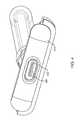
- FIG. 2illustrates a connector receptacle 210 according to an embodiment of the present invention. This figure, as with the other included figures, is shown for illustrative purposes and does not limit either the possible embodiments of the present invention or the claims.
- Connector receptacle 210may be located in an electronic device such as a portable computing device, tablet, desktop, or all-in-one computer, cell, smart, and media phone, storage device, portable media player, navigation system, monitor or other device.
- An enclosure for the devicemay include an opening such that surface 240 and contact 220 are accessible to a connector insert.
- Connector receptacle 210includes connector pin 220 .
- Connector pin 220may receive a positive voltage and may carry current provided by a power adapter or other device to a device that includes connector receptacle 210 .
- connector pin 220may provide a positive voltage and may provide power and current to an external device.
- Connector pin 220may be made relatively small by using material having a high conductivity.
- the power contact connector pin 220may be formed of a highly conductive material, such as brass, copper-nickel-silicon alloy, or a silver alloy.
- An insulating portion 230may isolate the positive supply on contact pin 220 from ground surface 240 .
- Ground surface 240may act as a ground return, as well as a portion of a shield surrounding the connector receptacle.
- Ground surface 240may have a curved surface as shown for easy insertion and extraction of a connector insert.
- magnets located in connector receptacle 210may attract a magnetic element in a connector insert.
- magnets located in a connector insertmay attract a magnetic element located in the connector receptacle 210 .
- magnetsmay be located behind ground surface 240 . These magnets may attract a magnetic element, such as an attraction plate made of a ferromagnetic material, in a connector insert.
- ground surface 240may be made relatively thin. Also, to avoid shunting the magnetic field away from the connector insert, ground surface 240 may be made of a relatively low conductivity material.
- ground surface 240may be made relatively large. This provides a larger surface for the magnets to attract a connector insert, and also provides an adequate ground return path.
- Ground surface 240may be formed using low carbon steel (1010), titanium copper, silver alloy, stainless or other steel, or other appropriate material. In this and other embodiments of the present invention, ground surface 240 may be formed as part of a shield for connector receptacle 210 .
- FIG. 3illustrates a cutaway view of a connector receptacle according to an embodiment of the present invention.
- magnets 260can be seen as being located behind ground surface 240 .
- various numbers of magnetsmay be used. For example, three, four, or other numbers of magnets may be used. These magnets may have alternating polarities to increase magnetic attraction. These magnets may be rare-earth, electromagnets, or other types of magnets.
- Connector receptacle 210further includes a spring 310 .
- This springis looped back onto itself as can be seen, and placed behind contact pin 220 .
- Spring 310may be formed using Titanium Copper (for example, Ti—Cu NKT322 EH), Phosphor-bronze (for example, C5210R-H), or other appropriate material.
- contact pin 220When connector receptacle 210 is mated with a connector insert, contact pin 220 may be depressed and may compress spring 310 . Spring 310 may thus provide a force to keep contact pin 220 in electrical contact with a corresponding contact on a connector insert.
- An example of such a connector insertis shown in the following figure.
- FIG. 4illustrates a portion of a connector insert according to an embodiment of the present invention.
- This connector insertincludes an attraction plate 410 and contacts 420 .
- An insulation area 422may isolate contact 420 from attraction plate 410 .
- Attraction plate 410may be made of low carbon steel, magnetic stainless steel, a ferromagnetic material, one or more magnets, or other appropriate material. Attraction plate 410 may form a portion of a ground path. Attraction plate 410 may be curved to mate with ground surface 240 in connector receptacle 210 . Contacts 420 may similarly be curved to accept contact pin 220 in connector receptacle 210 . Again, the curved shapes of attraction plate 410 and contacts 420 provide for a smooth and nonbinding insertion and extraction of the connector insert.
- the power contact 420may be formed of a highly conductive material, such as brass, copper-nickel-silicon alloy, or a silver alloy.
- FIG. 5illustrates a top view of a connector insert according to an embodiment of the present invention.
- cable 505includes a center conductor surrounded by braiding 540 .
- Braiding 540may be pulled back around an insulating jacket 507 .
- a crimping piece 530may be placed over braiding 540 and compressed, thereby making contact with braiding 540 .
- Crimping piece 530may include portions 532 and 534 , which may be spot-welded, soldered, or otherwise fixed to connector insert portion 520 .
- a center conductormay contact metal portion 550 , which in turn may connect to, or be part of, contact 420 .
- a power pathis formed through a conductor in cable 505 , the conductor connected to piece 550 , which in turn is connected to, or formed as part of, contact 420 .
- a ground pathis formed through braiding 540 of cable 505 , which contacts crimping piece 530 , which connects to metal piece 520 via tabs 534 and 532 .
- Attraction plate 410may be connected to, or may be formed of, the same piece, as connector insert portion 520 .
- FIG. 6illustrates a portion of a connector insert according to an embodiment of the present invention.
- heat shrink tube 610has been placed over an end of cable 505 .
- FIG. 7illustrates a front view of a portion of a connector insert according to an embodiment of the present invention.
- FIG. 8illustrates a top view of a connector insert according to an embodiment of the present invention.
- top piece 810has been fixed to the connector insert using fasteners 820 .
- An over-mold 830which may be soft plastic or other material, is placed over the connector insert to provide electrical isolation and a surface that may be handled by a user.
- connector receptacles in connector insertsmay be useful in providing power to a laptop computer.
- a connector insertmay plug into a side of the laptop, as shown in FIG. 1 .
- the weight of the cablemay pull down on the connector insert.
- the cablemay pull down sufficiently to disconnect a connector insert from its connector receptacle.
- embodiments of the present inventionmay adjust one or more dimensions in a connector receptacle to prevent this.
- embodiments of the present inventionmay provide a slight bind to a disconnect that occurs in a downward direction, while allowing an upward tug to easily disconnect a connector insert from the connector receptacle.
- One example of how to do thisis shown in the following figure.
- FIG. 9illustrates a cross-section of a connector insert and a connector receptacle according to an embodiment of the present invention.
- contact pin 220 in a connector receptaclemates with contact 420 in a connector insert.
- the connector insertmay bind somewhat when pulled in a downward direction.
- the displacement of contact pin 220may also allow the connector insert to be removed more easily when pulled in an upward direction.
- mating surfaces between a connector receptacle and the connector insertare shown as being curved. While this may have desirable properties as far as making for a smooth insertion and extraction of a connector insert from a connector receptacle, various manufacturing difficulties may be encountered. Accordingly, embodiments of the present invention may provide connector receptacles and connector inserts having flatter surfaces. Examples are shown in the following figures.
- FIG. 10illustrates a connector receptacle according to an embodiment of the present invention.
- Connector receptacle 1010includes contact pin 1020 , ground surface 1040 , and insulation ring 1030 .
- magnets 1050may be located behind ground surface 1040 .
- contact 220may be formed of a highly conductive material.
- the power contact pin 1020may be formed of a highly conductive material, such as brass, copper-nickel-silicon alloy, or a silver alloy.
- Ground surface 1040may be made of a less conductive material, as described above.
- ground surface 1040may be formed using low carbon steel (1010), titanium copper, silver alloy, stainless or other steel, or other appropriate material. Accordingly, ground surface 1040 may be made relatively large.
- ground surface 1040is relatively flat, as compared to ground surface 240 , and is also relatively larger.
- FIG. 11illustrates a cutaway view of a connector receptacle according to an embodiment of the present invention.
- a spring 1110may be used to provide a force to keep contact pin 1020 in contact with a contact on a connector insert when the connector insert is engaged with connector receptacle 1010 .
- stop 1115may be provided to limit the distance that contact pin 1020 may be depressed into connector receptacle 1010 .
- Spring 1110may be formed using Titanium Copper (for example, Ti—Cu NKT322 EH), Phosphor-bronze (for example, C5210R-H), or other appropriate material.
- FIG. 12illustrates a connector insert according to an embodiment of the present invention.
- This connector insertincludes contact 1220 , insulating layer 1222 , and attraction plate 1210 .
- Connectorfurther includes a shell 1230 and strain relief 1240 .
- the power contact 1220may be formed of a highly conductive material, such as brass, copper-nickel-silicon alloy, or a silver alloy.
- Shell 1230may be formed using aluminum or other material.
- FIG. 13illustrates a rear view of a connector insert according to an embodiment of the present invention. Again, this connector insert includes shell 1230 and strain relief 1240 .
- FIG. 14illustrates an exploded view of a connector insert according to an embodiment of the present invention.
- This connector insertincludes an attraction plate 1210 , insulating portion 1222 , power cap 1220 , power insulator cover 1410 , crimping piece 1430 , shell 1230 , and strain relief 1240 .
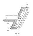
- FIG. 15illustrates a portion of a strain relief 1240 and a shell 1230 .
- Strain relief 1240includes raised portions 1510 . Raised portions 1510 may apply a spring force to maintain contact between pieces of the connector insert after assembly.
- power conductors in cable 505may be routed through power insulator 1410 and soldered to power cap 1220 .
- Braiding 1420may be pulled back as shown.
- Power cap 1220may be placed in power insulator 1222 , which is then placed in attraction plate 1210 .
- Crimping piece 1430may then be placed over braiding 1420 . An example of this is shown in the following figure.
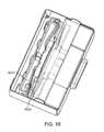
- FIG. 16illustrates portions of a connector insert according to an embodiment of the present invention.
- crimping piece 1430is engaged with attraction plate 1210 . This may be accomplished during assembly by sliding crimping piece 1430 along the cable, then rotating crimping piece 1430 counter-clockwise until contact is made between arms on crimping piece 1430 and attraction plate 1210 .
- Crimping piece 1430may be spot welded, laser welded, soldered, or otherwise fixed at arm portion 1610 to attraction plate 1210 , as shown.
- Attraction plate 1210may include recess 1620 to form a step to hold arm portion 1610 more securely.
- Crimping piece 1430may be crimped to form a secure connection.
- This crimpingmay be done by applying force in several directions around crimping piece at the same time.
- four tool-die elementsmay b used to crimp crimping piece 1430 .
- the resulting piecemay be injection molded to secure the various pieces to each other and prevent inadvertent electrical connections from forming.
- Shell 1230may then be placed over a portion of attraction plate 1210 .
- pins 1440may be aligned with groove 1520 in shell 1230 , as shown in FIG. 15 .
- Attraction plate 1210 and crimping piece 1430may be formed using low carbon steel, titanium, stainless or other steel, or other appropriate material.
- a ground connectionbefore any other connections are formed when a connector insert is attached to the connector receptacle.
- a ground connectionmay be the last connection to break. This may be referred to as a make-first break-last ground connection.
- Such a connectionmay be achieved by various embodiments of the present invention. Examples are shown in the following figures.
- FIG. 17illustrates a connector receptacle according to an embodiment of the present invention.
- This connector receptacleincludes contact 1710 surrounded by a ground connection 1735 .
- Insulating portion 1730may isolate power contacts 1720 from ground contact 1735 .
- Ground surface 1740may be in contact with ground contact 1735 .
- ground contact 1735is first to mate with a corresponding contact in the connector insert.
- Ground contact 1735is then depressed, thereby allowing power contact 1720 to mate with a corresponding contact in the connector insert.
- the power contact 1720 and ground contact 1735may be formed of a highly conductive material, such as brass, copper-nickel-silicon alloy, or a silver alloy.
- FIG. 18illustrates a top view of the connector receptacle of FIG. 17 .
- spring 1810is provided for power contact 1720 .
- a second spring 1820is included. This two-spring arrangement allows a ground contact and a power contact to be independently depressed, and allows a make-first break-last ground connection.
- Springs 1810 and 1820may be formed using Titanium Copper (for example, Ti—Cu NKT322 EH), Phosphor-bronze (for example, C5210R-H), or other appropriate material.
- FIGS. 19A and 19Billustrate a connector receptacle and connector insert according to an embodiment of the present invention.
- FIG. 19Aillustrates a front view of a connector receptacle having power contact 1920 and ground contacts 1930 on a mesa 1940 .
- FIG. 19Billustrates a top view of a connector insert and a connector receptacle according to an embodiment of the present invention.
- Connector receptacle 1901again has power contacts 1920 and ground contacts 1930 .
- Connector insert 1902includes a depressed portion 1950 to accept power contact 1920 , and raised portions 1960 to accept ground contacts 1930 .
- ground contacts 1930engage portions 1960 before contacts 1920 engage portion 1950 .
- ground contacts 1930disconnect from portions 1960 after contacts 1920 disconnects from portion 1950 .
- FIG. 20illustrates a connector receptacle and a connector insert according to an embodiment of the present invention.
- This figureincludes a connector receptacle 2001 and connector insert 2002 .
- ground contacts 2050engage ground contacts 2020 before power contact 2040 engages power contact 2010 .
- FIG. 21illustrates another connector receptacle according to an embodiment of the present invention.
- ground contacts 2120lead power contact 2110 to form a make-first break-last ground path.
- FIG. 22illustrates a connector receptacle according to an embodiment of the present invention.
- Connector receptacle 2201includes power contacts 2220 and ground contacts 2210 .
- ground contacts 2210are placed in front of power contacts 2220 , such that they engage corresponding ground contacts in a connector insert before power contacts 2220 engage corresponding power contacts in the connector insert.
Landscapes
- Details Of Connecting Devices For Male And Female Coupling (AREA)
Abstract
Description
Claims (20)
Priority Applications (2)
| Application Number | Priority Date | Filing Date | Title |
|---|---|---|---|
| US14/542,667US9461403B2 (en) | 2011-06-30 | 2014-11-17 | Robust magnetic connector |
| US15/281,066US9923290B2 (en) | 2011-06-30 | 2016-09-30 | Robust magnetic connector |
Applications Claiming Priority (3)
| Application Number | Priority Date | Filing Date | Title |
|---|---|---|---|
| US201161503598P | 2011-06-30 | 2011-06-30 | |
| US13/251,290US8888500B2 (en) | 2011-06-30 | 2011-10-03 | Robust magnetic connector |
| US14/542,667US9461403B2 (en) | 2011-06-30 | 2014-11-17 | Robust magnetic connector |
Related Parent Applications (1)
| Application Number | Title | Priority Date | Filing Date |
|---|---|---|---|
| US13/251,290ContinuationUS8888500B2 (en) | 2011-06-30 | 2011-10-03 | Robust magnetic connector |
Related Child Applications (2)
| Application Number | Title | Priority Date | Filing Date |
|---|---|---|---|
| US13/251,290ContinuationUS8888500B2 (en) | 2011-06-30 | 2011-10-03 | Robust magnetic connector |
| US15/281,066ContinuationUS9923290B2 (en) | 2011-06-30 | 2016-09-30 | Robust magnetic connector |
Publications (2)
| Publication Number | Publication Date |
|---|---|
| US20150207267A1 US20150207267A1 (en) | 2015-07-23 |
| US9461403B2true US9461403B2 (en) | 2016-10-04 |
Family
ID=47391090
Family Applications (3)
| Application Number | Title | Priority Date | Filing Date |
|---|---|---|---|
| US13/251,290Active2032-03-10US8888500B2 (en) | 2011-06-30 | 2011-10-03 | Robust magnetic connector |
| US14/542,667Expired - Fee RelatedUS9461403B2 (en) | 2011-06-30 | 2014-11-17 | Robust magnetic connector |
| US15/281,066ActiveUS9923290B2 (en) | 2011-06-30 | 2016-09-30 | Robust magnetic connector |
Family Applications Before (1)
| Application Number | Title | Priority Date | Filing Date |
|---|---|---|---|
| US13/251,290Active2032-03-10US8888500B2 (en) | 2011-06-30 | 2011-10-03 | Robust magnetic connector |
Family Applications After (1)
| Application Number | Title | Priority Date | Filing Date |
|---|---|---|---|
| US15/281,066ActiveUS9923290B2 (en) | 2011-06-30 | 2016-09-30 | Robust magnetic connector |
Country Status (5)
| Country | Link |
|---|---|
| US (3) | US8888500B2 (en) |
| EP (1) | EP2727191B1 (en) |
| KR (1) | KR101634883B1 (en) |
| CN (2) | CN103636074B (en) |
| WO (1) | WO2013003781A1 (en) |
Cited By (35)
| Publication number | Priority date | Publication date | Assignee | Title |
|---|---|---|---|---|
| US9923290B2 (en)* | 2011-06-30 | 2018-03-20 | Apple Inc. | Robust magnetic connector |
| US10169561B2 (en) | 2016-04-28 | 2019-01-01 | Bragi GmbH | Biometric interface system and method |
| US10201309B2 (en) | 2016-07-06 | 2019-02-12 | Bragi GmbH | Detection of physiological data using radar/lidar of wireless earpieces |
| US10297911B2 (en) | 2015-08-29 | 2019-05-21 | Bragi GmbH | Antenna for use in a wearable device |
| US10313781B2 (en) | 2016-04-08 | 2019-06-04 | Bragi GmbH | Audio accelerometric feedback through bilateral ear worn device system and method |
| US10344960B2 (en) | 2017-09-19 | 2019-07-09 | Bragi GmbH | Wireless earpiece controlled medical headlight |
| US10365443B2 (en)* | 2015-12-22 | 2019-07-30 | Panasonic Intellectual Property Management Co., Ltd. | Connector, receptacle, and plug |
| US10382854B2 (en) | 2015-08-29 | 2019-08-13 | Bragi GmbH | Near field gesture control system and method |
| US10397690B2 (en) | 2016-11-04 | 2019-08-27 | Bragi GmbH | Earpiece with modified ambient environment over-ride function |
| US10397688B2 (en) | 2015-08-29 | 2019-08-27 | Bragi GmbH | Power control for battery powered personal area network device system and method |
| US10398374B2 (en) | 2016-11-04 | 2019-09-03 | Bragi GmbH | Manual operation assistance with earpiece with 3D sound cues |
| US10412478B2 (en) | 2015-08-29 | 2019-09-10 | Bragi GmbH | Reproduction of ambient environmental sound for acoustic transparency of ear canal device system and method |
| US10412493B2 (en) | 2016-02-09 | 2019-09-10 | Bragi GmbH | Ambient volume modification through environmental microphone feedback loop system and method |
| US10433788B2 (en) | 2016-03-23 | 2019-10-08 | Bragi GmbH | Earpiece life monitor with capability of automatic notification system and method |
| US10448139B2 (en) | 2016-07-06 | 2019-10-15 | Bragi GmbH | Selective sound field environment processing system and method |
| US10506328B2 (en) | 2016-03-14 | 2019-12-10 | Bragi GmbH | Explosive sound pressure level active noise cancellation |
| US10575086B2 (en) | 2017-03-22 | 2020-02-25 | Bragi GmbH | System and method for sharing wireless earpieces |
| US10582289B2 (en) | 2015-10-20 | 2020-03-03 | Bragi GmbH | Enhanced biometric control systems for detection of emergency events system and method |
| US10620698B2 (en) | 2015-12-21 | 2020-04-14 | Bragi GmbH | Voice dictation systems using earpiece microphone system and method |
| US10672239B2 (en) | 2015-08-29 | 2020-06-02 | Bragi GmbH | Responsive visual communication system and method |
| US10681449B2 (en) | 2016-11-04 | 2020-06-09 | Bragi GmbH | Earpiece with added ambient environment |
| US10681450B2 (en) | 2016-11-04 | 2020-06-09 | Bragi GmbH | Earpiece with source selection within ambient environment |
| US10708699B2 (en) | 2017-05-03 | 2020-07-07 | Bragi GmbH | Hearing aid with added functionality |
| US10771881B2 (en) | 2017-02-27 | 2020-09-08 | Bragi GmbH | Earpiece with audio 3D menu |
| US10893353B2 (en) | 2016-03-11 | 2021-01-12 | Bragi GmbH | Earpiece with GPS receiver |
| US10896665B2 (en) | 2016-11-03 | 2021-01-19 | Bragi GmbH | Selective audio isolation from body generated sound system and method |
| US10904653B2 (en) | 2015-12-21 | 2021-01-26 | Bragi GmbH | Microphone natural speech capture voice dictation system and method |
| US11013445B2 (en) | 2017-06-08 | 2021-05-25 | Bragi GmbH | Wireless earpiece with transcranial stimulation |
| US11064408B2 (en) | 2015-10-20 | 2021-07-13 | Bragi GmbH | Diversity bluetooth system and method |
| US11116415B2 (en) | 2017-06-07 | 2021-09-14 | Bragi GmbH | Use of body-worn radar for biometric measurements, contextual awareness and identification |
| US11272367B2 (en) | 2017-09-20 | 2022-03-08 | Bragi GmbH | Wireless earpieces for hub communications |
| US11289849B2 (en)* | 2020-07-08 | 2022-03-29 | Jayesh Jani | Magnetized data connector assembly |
| US11380430B2 (en) | 2017-03-22 | 2022-07-05 | Bragi GmbH | System and method for populating electronic medical records with wireless earpieces |
| US11544104B2 (en) | 2017-03-22 | 2023-01-03 | Bragi GmbH | Load sharing between wireless earpieces |
| US11694771B2 (en) | 2017-03-22 | 2023-07-04 | Bragi GmbH | System and method for populating electronic health records with wireless earpieces |
Families Citing this family (44)
| Publication number | Priority date | Publication date | Assignee | Title |
|---|---|---|---|---|
| US7351066B2 (en) | 2005-09-26 | 2008-04-01 | Apple Computer, Inc. | Electromagnetic connector for electronic device |
| US7311526B2 (en) | 2005-09-26 | 2007-12-25 | Apple Inc. | Magnetic connector for electronic device |
| US9300081B2 (en) | 2010-02-02 | 2016-03-29 | Charles Albert Rudisill | Interposer connectors with magnetic components |
| US9065205B2 (en) | 2011-08-11 | 2015-06-23 | Apple Inc. | Connector insert having a cable crimp portion with protrusions and a receptacle having label in the front |
| US10680383B2 (en) | 2013-03-14 | 2020-06-09 | Apex Technologies, Inc. | Linear electrode systems for module attachment with non-uniform axial spacing |
| US9559456B2 (en)* | 2013-03-15 | 2017-01-31 | Google Technology Holdings LLC | Magnetic electrical connection system for an electronic device |
| KR20150047780A (en)* | 2013-10-25 | 2015-05-06 | 삼성전자주식회사 | Electronic device with electrical connector |
| JP6150435B2 (en)* | 2013-12-27 | 2017-06-21 | 日本航空電子工業株式会社 | Magnetic connector |
| US9531118B2 (en) | 2014-07-10 | 2016-12-27 | Norman R. Byrne | Electrical power coupling with magnetic connections |
| GB2533258A (en)* | 2014-09-12 | 2016-06-22 | Ifpl Group Ltd | Electrical Connectors |
| KR102360490B1 (en)* | 2014-12-24 | 2022-02-09 | 삼성전자주식회사 | An electric connector |
| US9755355B2 (en)* | 2015-04-09 | 2017-09-05 | Apple Inc. | Connection module for a portable electronic device |
| US9774147B1 (en)* | 2015-10-14 | 2017-09-26 | CSC Holdings, LLC | Cable having an integrated antenna |
| EP3159978B1 (en)* | 2015-10-20 | 2020-11-25 | ITT Manufacturing Enterprises LLC | Receptacle, connector and connection interfaces with coupling mechanisms |
| CA2956264A1 (en)* | 2016-01-28 | 2017-07-28 | Bombardier Recreational Products Inc. | Connector assembly for a helmet |
| US10177507B2 (en) | 2016-02-12 | 2019-01-08 | Norman R. Byrne | Electrical power load switch with connection sensor |
| WO2017211041A1 (en)* | 2016-06-08 | 2017-12-14 | 广东百事泰电子商务股份有限公司 | Intelligent charger and power supply connection apparatus |
| MX371369B (en) | 2016-10-07 | 2020-01-28 | Norman R Byrne | Electrical power cord with intelligent switching. |
| CN116805771A (en) | 2017-08-15 | 2023-09-26 | 梅西莫股份有限公司 | Waterproof connector for noninvasive patient monitor |
| US10355402B2 (en) | 2017-09-29 | 2019-07-16 | Apple Inc. | Axisymmetric magnetic articulating connector |
| WO2019159153A1 (en) | 2018-02-19 | 2019-08-22 | Bombardier Recreational Products Inc. | Helmet |
| US10312631B1 (en) | 2018-02-20 | 2019-06-04 | The Boeing Company | Detachable communications connector for vehicle stores and method therefor |
| CN108564158A (en)* | 2018-04-14 | 2018-09-21 | 佛山市顺德区贝贝健电子科技有限公司 | A kind of special menu chip of cooking machine |
| US10821290B2 (en)* | 2018-07-13 | 2020-11-03 | Greatbatch Ltd. | Lead adaptor double port for implantable neuro-stimulation system |
| CN109020009A (en)* | 2018-08-23 | 2018-12-18 | 江苏海事职业技术学院 | Ballast water treatment plant with remote control |
| US11424561B2 (en) | 2019-07-03 | 2022-08-23 | Norman R. Byrne | Outlet-level electrical energy management system |
| US11025002B1 (en)* | 2019-11-12 | 2021-06-01 | Google Llc | Magnetic cable adapters and connectors and methods of installing cables implementing same |
| FR3107399B1 (en)* | 2020-02-13 | 2022-06-03 | Schneider Electric Ind Sas | Magnetic connector and group of magnetic connectors |
| US11495912B2 (en) | 2020-04-10 | 2022-11-08 | Water Pik, Inc. | Charging connector for oral health devices |
| USD955977S1 (en) | 2020-04-10 | 2022-06-28 | Water Pik, Inc. | Charging connector |
| US11009906B1 (en) | 2020-05-01 | 2021-05-18 | Dell Products L.P. | Information handling system display adaptive magnetic sound bar attachment |
| US11424573B2 (en) | 2020-09-24 | 2022-08-23 | Apple Inc. | Magnetic connectors with self-centering floating contacts |
| US11811174B2 (en) | 2020-09-25 | 2023-11-07 | Apple Inc. | Low-profile axisymmetric power connectors |
| US12138466B2 (en) | 2021-03-12 | 2024-11-12 | Greatbatch Ltd. | Cable-less lead adapter for implantable neurostimulator system |
| US12261385B2 (en) | 2022-03-07 | 2025-03-25 | Apple Inc. | Power connector with asymmetric insertion-to-extraction force ratio |
| US12273609B2 (en) | 2022-10-18 | 2025-04-08 | Dell Products L.P. | Camera sensor and lens housing structure for enhanced manufacture assembly and repair |
| US12306676B2 (en) | 2022-10-18 | 2025-05-20 | Dell Products L.P. | Information handling system keyboard with rapid assembly and disassembly to aid recycling |
| US11650671B1 (en) | 2022-10-18 | 2023-05-16 | Dell Products L.P. | Information handling system keyboard with rapid assembly and disassembly to aid recycling |
| US12085993B2 (en) | 2022-10-18 | 2024-09-10 | Dell Products L.P. | Information handling system coupling device for improved assembly, disassembly and repair |
| US12284429B2 (en) | 2022-10-18 | 2025-04-22 | Dell Products L.P. | Camera housing structure for enhanced manufacture assembly and repair |
| US12245372B2 (en) | 2022-10-18 | 2025-03-04 | Dell Products L.P. | Information handling system and peripheral printed circuit board having non-homogeneous substrate material and integrated thermal solution |
| US12235683B2 (en) | 2022-10-18 | 2025-02-25 | Dell Products L.P. | Information handling system display rapid panel assembly and repair |
| US11856719B1 (en) | 2022-10-18 | 2023-12-26 | Dell Products L.P. | Information handling system mouse with rapid assembly and disassembly to aid recycling |
| US12306677B2 (en) | 2022-10-18 | 2025-05-20 | Dell Products L.P. | Information handling system with rapid assembly and disassembly to aid recycling |
Citations (166)
| Publication number | Priority date | Publication date | Assignee | Title |
|---|---|---|---|---|
| US2170287A (en) | 1937-06-14 | 1939-08-22 | Walter L Kinnebrew | Detachable electrical connector |
| US2234982A (en) | 1939-04-07 | 1941-03-18 | Donald S Ross | Flush floor electric outlet |
| US3144527A (en) | 1961-09-13 | 1964-08-11 | Manuel J Tolegian | Magnetic electrical coupling |
| US3363214A (en) | 1966-01-21 | 1968-01-09 | Charles T. Wright | Magnetic plug adapter |
| US3431428A (en) | 1967-04-19 | 1969-03-04 | Andrew F Van Valer | Safety vehicle power distribution system |
| US3521216A (en) | 1968-06-19 | 1970-07-21 | Manuel Jerair Tolegian | Magnetic plug and socket assembly |
| US3713370A (en) | 1970-11-06 | 1973-01-30 | C Prijn | Arrangement for coupling a flash bulb holder to a camera |
| US3786391A (en) | 1972-07-11 | 1974-01-15 | W Mathauser | Magnetic self-aligning electrical connector |
| US3808577A (en) | 1973-03-05 | 1974-04-30 | W Mathauser | Magnetic self-aligning quick-disconnect for a telephone or other communications equipment |
| US3810258A (en) | 1972-07-11 | 1974-05-07 | W Mathauser | Quick connect electrical coupler |
| US3868160A (en) | 1971-10-14 | 1975-02-25 | Jorge Eduardo Kersman | Protective electric coupling |
| US4211456A (en) | 1979-01-31 | 1980-07-08 | Schick Laboratories, Inc. | Magnetic electrical connectors |
| US4317969A (en) | 1978-09-01 | 1982-03-02 | Hannes Riegler | Electrical line-connector |
| EP0112019A1 (en) | 1982-11-17 | 1984-06-27 | AMP INCORPORATED (a New Jersey corporation) | Electrical plug connector |
| FR2566195A1 (en) | 1984-06-13 | 1985-12-20 | Jonathan Jean Pierre | Connector having contact attraction using electromagnetic force |
| GB2174556A (en) | 1985-05-04 | 1986-11-05 | Stc Plc | Remote operation of electrical connector using magnetism |
| US4669791A (en) | 1984-09-06 | 1987-06-02 | Integrated Circuit Systems, Ltd. | Connector apparatus |
| US4712234A (en) | 1985-03-01 | 1987-12-08 | The Siemon Company | Multi-purpose modular jack connecting block |
| DE3622948A1 (en) | 1986-07-08 | 1988-01-21 | Heinz Eichholz | Contact arrangement for producing a conductive electrical connection |
| EP0289208A2 (en) | 1987-04-30 | 1988-11-02 | Sony Corporation | Electrical connector |
| US4810202A (en) | 1983-04-14 | 1989-03-07 | Ab Stratos | Connector device |
| US4844582A (en) | 1987-12-09 | 1989-07-04 | Giannini Gabriel M | Hybrid electro-optical connectors |
| DE3904708C1 (en) | 1989-02-16 | 1990-01-18 | Atlanta-Kabel-Steinmueller Kg, 5880 Luedenscheid, De | Electrical plug device |
| JPH0359973B2 (en) | 1983-03-31 | 1991-09-12 | Tokyo Shibaura Electric Co | |
| FR2665305A1 (en) | 1990-07-24 | 1992-01-31 | Sagem | Connector which includes a vandal-proof socket and an interacting plug |
| JPH04296475A (en) | 1991-03-26 | 1992-10-20 | Toshiba Corp | Connector device |
| FR2685981A1 (en) | 1992-01-08 | 1993-07-09 | Seb Sa | Safe electrical connection device |
| JPH05335051A (en) | 1992-06-02 | 1993-12-17 | Mitsubishi Electric Corp | Connector |
| WO1994006174A1 (en) | 1992-09-07 | 1994-03-17 | Mitsuba Electric Manufacturing Co., Ltd. | Connecting device |
| EP0573471B1 (en) | 1991-02-27 | 1994-10-12 | Esslinger, Udo | Electromechanical connecting device |
| JPH076817A (en) | 1993-06-15 | 1995-01-10 | Hitachi Ltd | Connect device |
| US5382476A (en) | 1993-02-20 | 1995-01-17 | Basf Aktiengesellschaft | Recycling of cured aminoplast resins |
| US5382167A (en) | 1993-12-03 | 1995-01-17 | Eastman Kodak Company | Magnetically secured temporary electrical connector |
| WO1995006970A1 (en) | 1993-09-02 | 1995-03-09 | Hubbell Incorporated | Electrical connector assembly, especially for electric vehicle |
| US5692786A (en) | 1996-08-16 | 1997-12-02 | Securitech Group, Inc. | Electromagnetic door assembly |
| US5696861A (en) | 1996-08-13 | 1997-12-09 | Schimmeyer; Werner K. | Method and apparatus for simultaneously connecting data/signal communication lines and power lines to a data/RF receiver/transmitter |
| US5704802A (en) | 1996-06-14 | 1998-01-06 | Maxconn Incorporated | Modular jack assembly |
| US5812356A (en) | 1996-08-14 | 1998-09-22 | Dell U.S.A., L.P. | Computer docking system having an electromagnetic lock |
| US5829987A (en) | 1995-04-01 | 1998-11-03 | Fritsch; Klaus-Dieter | Electromechanical connection device |
| JPH119467A (en) | 1997-06-26 | 1999-01-19 | Hamada Seidensha:Kk | Power supply cord with temperature control function of electric cooker for hotplate or the like, and temperature controller unit used for power supply cord with temperature control function |
| US5865645A (en) | 1996-02-28 | 1999-02-02 | Siemens Aktiengesellschaft | Angular press-fit plug connector for press-fitting into holes in a printed circuit board |
| DE19820691A1 (en) | 1997-07-29 | 1999-02-18 | Siemens Ag | Motor vehicle control device e.g. for airbag system |
| US5873737A (en) | 1996-02-16 | 1999-02-23 | Yazaki Corporation | Connector with low passing-through magnet force |
| US5885100A (en) | 1997-05-12 | 1999-03-23 | Molex Incorporated | Electrical connector with light transmission means |
| JPH11144803A (en) | 1997-11-06 | 1999-05-28 | Hiromi Hizume | Supra-connector |
| US5921783A (en)* | 1995-04-01 | 1999-07-13 | Klaus-Dieter Fritsch | Electromechanical connection device |
| US5941729A (en) | 1997-09-10 | 1999-08-24 | International Business Machines Corporation | Safe-snap computer cable |
| US5954520A (en) | 1996-12-19 | 1999-09-21 | Schmidt; William P. | Magnetic coupler |
| JPH11273770A (en) | 1998-03-20 | 1999-10-08 | Mitsubishi Electric Corp | Input / output terminal structure of electronic equipment |
| US6007363A (en) | 1998-03-18 | 1999-12-28 | Thomson Consumer Electronics, Inc. | Magnetically latchable device for electrically coupling a power source to a circuit |
| JP2000012145A (en) | 1998-06-24 | 2000-01-14 | Matsushita Electric Ind Co Ltd | Magnet attracting type connector |
| JP2000030806A (en) | 1997-05-30 | 2000-01-28 | Molex Inc | Shielded-electric connector assembly |
| US6030229A (en) | 1997-03-11 | 2000-02-29 | Sumitomo Electric Industries, Ltd | Electromagnetic detachable connector |
| US6042385A (en) | 1996-06-27 | 2000-03-28 | Sumitomo Wiring Systems, Ltd. | Connector for charging |
| US6088752A (en) | 1998-08-06 | 2000-07-11 | Mobility Electronics, Inc. | Method and apparatus for exchanging information between buses in a portable computer and docking station through a bridge employing a serial link |
| US6094122A (en)* | 1999-09-08 | 2000-07-25 | Ford Motor Company | Mechanical locking connection for electric terminals |
| US6165006A (en) | 1998-10-16 | 2000-12-26 | Hon Hai Precision Ind. Co., Ltd. | Cable connector |
| US6174194B1 (en) | 1998-11-09 | 2001-01-16 | Molex Incorporated | Add-on electrical assembly with light transmission means |
| US6183264B1 (en) | 1999-07-19 | 2001-02-06 | HARSáNYI EDUARDO G. | Safety receptacle for electrical outlets |
| US6211581B1 (en) | 1997-11-28 | 2001-04-03 | Harvard M. Farrant | Power bar with remote control |
| US6219267B1 (en) | 1996-12-03 | 2001-04-17 | Jacques Andres | Electric supply system, corresponding terminal and mounting base |
| US6217339B1 (en) | 1998-07-07 | 2001-04-17 | Seiko Instruments Inc. | Power source connecting apparatus and electronic appliance having the same power source connecting apparatus |
| US6238219B1 (en) | 1998-11-17 | 2001-05-29 | Hon Hai Precision Ind. Co., Ltd. | Electrical connection method |
| US6250931B1 (en) | 1999-11-02 | 2001-06-26 | Kinetic Group L.L.C. | Detachable power supply apparatus |
| US6267602B1 (en) | 1999-11-02 | 2001-07-31 | Kinetic Group L.L.C. | Detachable power supply apparatus |
| US20020002004A1 (en) | 1998-08-20 | 2002-01-03 | Junichi Akama | Balanced-transmission cable-and-connector unit |
| US6340302B1 (en) | 2001-02-06 | 2002-01-22 | Micron Technology, Inc. | Apparatus for establishing an electrical connection with a wafer to facilitate wafer-level burn-in and methods |
| JP2002056929A (en) | 2000-08-11 | 2002-02-22 | Zojirushi Corp | Magnet plug |
| US6358069B2 (en) | 2000-03-28 | 2002-03-19 | Yazaki Corporation | Connecting structure of shielded wire for shield connector |
| US20020044746A1 (en) | 2000-07-12 | 2002-04-18 | Mitel Semiconductor Ab | Self powered data communication optical fiber cable extender |
| US20020054686A1 (en) | 2000-11-06 | 2002-05-09 | Hajime Tabata | Connecting cable for helmets |
| US6419521B2 (en)* | 2000-06-12 | 2002-07-16 | Autonetworks Technologies, Ltd. | Shield connector |
| US6431902B1 (en) | 2001-09-10 | 2002-08-13 | Hon Hai Precision Ind. Co., Ltd. | Electrical connector having an improved latch mechanism |
| US20020123250A1 (en) | 2001-02-14 | 2002-09-05 | Donglei Wang | Plug/socket assembly |
| JP2002270279A (en) | 2001-03-07 | 2002-09-20 | Hirose Electric Co Ltd | Electrical connector having cover case and method of manufacturing cover case |
| US6464509B1 (en) | 2001-04-26 | 2002-10-15 | International Business Machines Corporation | System and method requiring zero insertion force and positive retention of removable storage media in a data storage subsystem |
| US6466718B1 (en) | 1999-12-29 | 2002-10-15 | Emc Corporation | Method and apparatus for transmitting fiber-channel and non-fiber channel signals through common cable |
| US6478614B1 (en) | 2001-04-20 | 2002-11-12 | De'longhi S.P.A. | Easy-detach electrical connector for kitchen appliance |
| US6485338B1 (en) | 2001-09-10 | 2002-11-26 | Hon Hai Precision Ind. Co., Ltd. | Compression connector |
| JP2002367724A (en) | 2001-06-05 | 2002-12-20 | Toshiba Tec Corp | POWER CONNECTION AND ELECTRIC APPARATUS HAVING THE POWER CONNECTION |
| US6522033B1 (en) | 1997-09-29 | 2003-02-18 | Hayim Nevo | High sensitivity electrical switching circuit |
| US6528746B2 (en) | 2001-04-27 | 2003-03-04 | Lyall Assemblies, Inc. | Electrical connector system |
| US6527570B1 (en) | 2001-10-03 | 2003-03-04 | National Presto Industries, Inc. | Quick-release appliance cord assembly |
| JP2003082519A (en) | 2001-09-12 | 2003-03-19 | Honda Access Corp | Structure for connecting external conductor of helmet for riding on vehicle |
| US6545577B2 (en) | 2001-06-18 | 2003-04-08 | Hewlett-Packard Company | Frictionless pen ejector mechanism |
| US6561815B1 (en) | 1999-07-02 | 2003-05-13 | Siegfried Schmidt | Electromechanical connecting device |
| US6565363B2 (en) | 2001-08-30 | 2003-05-20 | Eric Downing | Magnetic modular jack |
| JP2003163046A (en) | 2001-11-27 | 2003-06-06 | Polymatech Co Ltd | Sealing connector and its making method and interior acoustic structure of compact information communication device |
| GB2383476A (en) | 2001-12-21 | 2003-06-25 | Slab Dsp Ltd | Audio jack with automatic plug detection and identification |
| US20030148643A1 (en) | 2002-02-06 | 2003-08-07 | Nishimuru Yoji | Power plug |
| US6616468B2 (en) | 2000-04-17 | 2003-09-09 | Fujikura Ltd. | Connector and electric connection structure |
| US6623276B2 (en) | 2001-01-02 | 2003-09-23 | Furas, S.A. | Safety connector for household table-top electrical appliances |
| DE10242645A1 (en) | 2002-09-13 | 2004-03-25 | Magcode Ag | Method of creating electrical connection to modules e.g. in motor vehicle, by using magnetic bodies in current providing unit and current receiving unit to form contact automatically |
| US20040077187A1 (en) | 2002-04-29 | 2004-04-22 | Regal Ware, Inc. | Detachable breakaway power supply source |
| US6727477B1 (en) | 2003-03-28 | 2004-04-27 | Lyu Jan Co., Ltd. | Temperature controller |
| DE202004003202U1 (en) | 2004-03-02 | 2004-04-29 | Magcode Ag | Electrical connection device |
| US6733333B1 (en) | 2003-03-05 | 2004-05-11 | Wilson Chen | Transmission cable having operation status indicator means |
| JP2004206973A (en) | 2002-12-24 | 2004-07-22 | Matsushita Electric Works Ltd | Magnet type outlet adapter |
| US6773312B2 (en) | 2001-09-04 | 2004-08-10 | Era-Contact Gmbh | Electrical pressure contact |
| US20040184295A1 (en) | 2001-06-28 | 2004-09-23 | Duncan Robertson | Power plug |
| DE10333403A1 (en) | 2003-07-14 | 2004-09-23 | Albert Ackermann Gmbh & Co. Kg | Electrical lead cable plug-in connection system e.g. for nursing zone adjacent hospital bed, using magnetic force for preventing accidental release of plug-in connection |
| US20040209489A1 (en) | 2003-04-21 | 2004-10-21 | Clapper Edward O. | Apparatus for automatic docking |
| WO2004095647A1 (en) | 2003-04-22 | 2004-11-04 | Twinsaver Co., Ltd | Safety wire connector |
| US6814626B2 (en) | 2002-10-21 | 2004-11-09 | L & K Precision Industry Co., Ltd. | Electrical connector for chargeable battery |
| US6815610B2 (en) | 2002-09-24 | 2004-11-09 | Yazaki Corporation | Electromagnetic shielding structure |
| US20040224539A1 (en) | 2003-05-07 | 2004-11-11 | Dell Products L.P. | Computer System Having a Releasable Connector |
| US6821126B2 (en) | 2000-12-14 | 2004-11-23 | Magcode Ag | Electromechanical connecting device |
| US20040257741A1 (en) | 2001-11-16 | 2004-12-23 | Jean-Christophe Cuny | Control and protection module of a switch device |
| WO2005006913A1 (en) | 2003-07-16 | 2005-01-27 | Taizo Michida | Alert apparatus for use with fasteners |
| US20050082915A1 (en) | 2003-10-14 | 2005-04-21 | Conair Corporation | Breakaway power supply device |
| US20050208783A1 (en) | 2004-03-17 | 2005-09-22 | Jamco Corporation | Audio plug |
| US20050255719A1 (en) | 2002-09-13 | 2005-11-17 | Hermann Heidlein | Electric connecting device |
| US20050255718A1 (en) | 2002-07-16 | 2005-11-17 | Mcleish Graham J | Connector |
| US20050255716A1 (en) | 2004-04-28 | 2005-11-17 | Semiconductor Energy Laboratory Co., Ltd. | Laser irradiation method and method for manufacturing semiconductor device using the same |
| US6966781B1 (en) | 1996-06-22 | 2005-11-22 | Achim Bullinger | Electromechanical connector |
| US6976882B2 (en) | 2004-03-02 | 2005-12-20 | Conair Corporation | Detachable power supply apparatus |
| US6991483B1 (en) | 2002-06-11 | 2006-01-31 | Henry Milan | Flash memory drive with quick connector |
| US20060067690A1 (en) | 2004-09-29 | 2006-03-30 | Tatum Jimmy A | Optical cables for consumer electronics |
| JP2006095040A (en) | 2004-09-29 | 2006-04-13 | Keakomu:Kk | Connection device |
| US20060164447A1 (en) | 2005-01-20 | 2006-07-27 | Zih Corp. | Ethernet and USB powered printers and methods for supplying ethernet and USB power to a printer |
| US7097499B1 (en)* | 2005-08-18 | 2006-08-29 | John Mezzalingua Associates, Inc. | Coaxial cable connector having conductive engagement element and method of use thereof |
| US7112103B2 (en) | 2003-10-17 | 2006-09-26 | Hon Hai Precision Ind. Co., Ltd | Electrical connector having reliable contacts |
| US7121707B2 (en) | 2002-02-14 | 2006-10-17 | Plastic Inventions And Patents, Inc. | Illuminated electrical cords and outlets |
| US20070067654A1 (en) | 2005-09-20 | 2007-03-22 | Masaharu Adachi | Power adapter including peripheral unit capable of supplying power for computer and the peripheral unit |
| US20070072443A1 (en) | 2005-09-26 | 2007-03-29 | Apple Computer, Inc. | Magnetic connector for electronic device |
| US7198295B2 (en) | 2002-11-26 | 2007-04-03 | Deere & Company | Retainer arrangement connecting operating unit to a vehicle |
| US20070085516A1 (en) | 2005-06-30 | 2007-04-19 | Fenwick Stephen C | Connector arrangements on a power supply unit |
| US20070107068A1 (en) | 2005-10-14 | 2007-05-10 | Oqo, Inc. | Hybrid hardware/firmware multi-axis accelerometers for drop detect and tumble detect |
| US7217142B1 (en) | 2006-07-03 | 2007-05-15 | Hon Hai Precision Ind. Co., Ltd. | Cable connector assembly with improved contacts |
| US20070112989A1 (en) | 2005-07-13 | 2007-05-17 | Kabushiki Kaisha Toshiba | Information processing apparatus and video signal output control method |
| US7247046B1 (en) | 2006-07-03 | 2007-07-24 | Hon Hai Precision Ind. Co., Ltd | Connector assembly having status indator means |
| US20070184674A1 (en) | 2004-02-09 | 2007-08-09 | Franz Koch | Contact arrangement having a battery and an electrical line |
| US7264479B1 (en)* | 2006-06-02 | 2007-09-04 | Lee Vincent J | Coaxial cable magnetic connector |
| US7306479B1 (en) | 2006-07-05 | 2007-12-11 | Hon Hai Precision Ind. Co., Ltd. | Cable connector assembly with strain relief member |
| US7329128B1 (en) | 2007-01-26 | 2008-02-12 | The General Electric Company | Cable connector |
| US7332990B2 (en) | 2004-01-29 | 2008-02-19 | Asustek Computer Inc. | Portable computer |
| US7351066B2 (en) | 2005-09-26 | 2008-04-01 | Apple Computer, Inc. | Electromagnetic connector for electronic device |
| US7364433B2 (en) | 2003-11-10 | 2008-04-29 | Magcode Ag | Electrical connecting apparatus |
| US7419378B2 (en) | 2006-11-14 | 2008-09-02 | Samsung Electronics Co., Ltd. | Socket for testing semiconductor package |
| US20080211310A1 (en) | 2006-12-06 | 2008-09-04 | Det International Holding Limited | Portable power supply apparatus capable of receiving ac or dc input power |
| US7429188B2 (en) | 2006-07-03 | 2008-09-30 | Hon Hai Precision Ind. Co., Ltd. | Cable connector assembly with status indicator means |
| US7445452B1 (en) | 2007-11-30 | 2008-11-04 | Hon Hai Precision Ind. Co., Ltd. | Electrical interconnection system having magnetic retention device |
| US7497693B1 (en) | 2007-11-30 | 2009-03-03 | Hon Hai Precision Ind. Co., Ltd. | Electrical interconnection system using magnetic retention |
| US20090142962A1 (en) | 2007-11-30 | 2009-06-04 | Hon Hai Precision Ind. Co., Ltd | Electrical connector with improved contact arrangement |
| CN101515685A (en) | 2008-02-21 | 2009-08-26 | 鸿富锦精密工业(深圳)有限公司 | Electric connector, and plug and socket thereof |
| US20090269943A1 (en) | 2007-12-24 | 2009-10-29 | Craig Palli | Magnetic and Locking Cable Connectors |
| US7625213B1 (en) | 2008-12-23 | 2009-12-01 | Plastoform Industries Ltd. | Magnetic means for detachably and rotatably connecting components in an audio speaker system |
| US20100080563A1 (en) | 2008-09-30 | 2010-04-01 | Apple Inc. | Magnetic connector with optical signal path |
| US7717733B1 (en) | 2008-12-10 | 2010-05-18 | Hon Hai Precision Ind. Co., Ltd. | Cable assembly having enhanced interconnection device thereof |
| DE202010002522U1 (en) | 2010-02-18 | 2010-07-08 | Chen, Ming Jen | Electric plug |
| US7775801B2 (en) | 2005-01-05 | 2010-08-17 | Microsoft Corporation | Device interfaces with non-mechanical securement mechanisms |
| US20110092081A1 (en) | 2009-10-20 | 2011-04-21 | Apple Inc. | Magnetic connector having a unitary housing |
| US7931472B2 (en) | 2008-01-07 | 2011-04-26 | Arnon Haim David | Apparatus for transferring electric power from a mobile unit placed in various orientation on a stationary unit |
| US8043123B2 (en) | 2009-10-15 | 2011-10-25 | Compal Electronics, Inc. | Power receptacle for portable electronic device |
| US8057248B1 (en) | 2008-04-17 | 2011-11-15 | Sherman Neil S | Connector for mounting to a circuit board |
| US8172580B1 (en) | 2011-02-24 | 2012-05-08 | Tennrich International Corp. | Power adapter |
| US20120148196A1 (en) | 2005-11-18 | 2012-06-14 | Applied Optical Systems, Inc | Versatile system for configurable hybrid fiber-optic/electrical connectors |
| US8241043B1 (en) | 2011-04-01 | 2012-08-14 | Cheng Uei Precision Industry Co., Ltd. | Probe connector |
| US20120295451A1 (en) | 2011-05-20 | 2012-11-22 | Smart Power Solutions, Inc | Magnetic connecting device |
| US20130040470A1 (en) | 2011-08-11 | 2013-02-14 | Apple Inc. | Magnetic insert and receptacle for connector system |
| US20140087569A1 (en) | 2012-09-26 | 2014-03-27 | Kc Magcon, Inc. | Magnetic-enabled connector device |
| US20140235075A1 (en) | 2013-02-20 | 2014-08-21 | Sps Inc. | Magnetic connector module having power supply blocking circuit |
| US20140287601A1 (en) | 2013-03-22 | 2014-09-25 | Samsung Electronics Co., Ltd. | Magnetic connection device |
| US8888500B2 (en)* | 2011-06-30 | 2014-11-18 | Apple Inc. | Robust magnetic connector |
| US20150111398A1 (en) | 2013-10-17 | 2015-04-23 | Corning Cable Systems Llc | Magnetic coupling with low moment articulated plug |
| US20150214654A1 (en) | 2014-01-24 | 2015-07-30 | Foxconn Interconnect Technology Limited | Cable connector assembly with a shorter size and method of assembling the same |
Family Cites Families (20)
| Publication number | Priority date | Publication date | Assignee | Title |
|---|---|---|---|---|
| GB1232922A (en) | 1968-04-04 | 1971-05-26 | ||
| JPS509990B1 (en) | 1970-06-01 | 1975-04-17 | ||
| US4004298A (en)* | 1975-03-31 | 1977-01-25 | Sinai Hospital Of Detroit | Magnetically aligned releasable connector |
| JPH0359973A (en) | 1989-07-27 | 1991-03-14 | Fujitsu Ltd | electrical connections |
| AU4639393A (en) | 1992-06-16 | 1994-01-04 | Dill Systems Corp. | Magnetic circuits for communicating data |
| US5662480A (en)* | 1994-06-28 | 1997-09-02 | Smk Co., Ltd. | Surface mount type coaxial connector connecting coaxial cable to substrate |
| TW281724B (en) | 1995-03-06 | 1996-07-21 | Advanced Micro Devices Inc | Apparatus and method to uniquely identify similarly connected electrical devices |
| JP2003187924A (en) | 2001-12-17 | 2003-07-04 | Pioneer Electronic Corp | Connector, electronic device, and control method of electronic device |
| US7871272B2 (en)* | 2009-03-20 | 2011-01-18 | Casco Products Corporation | Sliding window magnetic electrical connector |
| TWI382613B (en)* | 2009-05-04 | 2013-01-11 | Hon Hai Prec Ind Co Ltd | Electrical connector |
| CN201667447U (en)* | 2009-12-15 | 2010-12-08 | 富士康(昆山)电脑接插件有限公司 | Electric connector |
| CN101752646A (en)* | 2010-01-27 | 2010-06-23 | 力帆实业(集团)股份有限公司 | Antenna positioning device |
| US8388354B1 (en)* | 2011-12-01 | 2013-03-05 | Cheng Uei Precision Industry Co., Ltd. | Electrical connector |
| US8465296B1 (en)* | 2012-02-21 | 2013-06-18 | Cheng Uei Precision Industry Co., Ltd. | Electrical connector |
| CN203800333U (en) | 2014-01-20 | 2014-08-27 | 富士康(昆山)电脑接插件有限公司 | Electrical connector assembly |
| CN203760751U (en)* | 2014-02-25 | 2014-08-06 | 番禺得意精密电子工业有限公司 | Electric connector assembly |
| US9490578B2 (en)* | 2014-05-13 | 2016-11-08 | Foxconn Interconnect Technology Limited | Electrical connector assembly having guiding means |
| CN204633034U (en)* | 2015-01-27 | 2015-09-09 | 富士康(昆山)电脑接插件有限公司 | Electrical Connectors and Butt Connectors |
| TWM501006U (en)* | 2015-03-02 | 2015-05-11 | Quanta Comp Inc | Electronic products and their wire sets |
| CN106159525B (en)* | 2015-03-27 | 2018-03-06 | 富士康(昆山)电脑接插件有限公司 | Magnetic-extraction connector and micro coaxial cable connector assembly |
- 2011
- 2011-10-03USUS13/251,290patent/US8888500B2/enactiveActive
- 2012
- 2012-06-29EPEP12743573.3Apatent/EP2727191B1/ennot_activeNot-in-force
- 2012-06-29CNCN201280032359.6Apatent/CN103636074B/ennot_activeExpired - Fee Related
- 2012-06-29CNCN201610881127.8Apatent/CN106711642B/ennot_activeExpired - Fee Related
- 2012-06-29WOPCT/US2012/045056patent/WO2013003781A1/enactiveApplication Filing
- 2012-06-29KRKR1020147002248Apatent/KR101634883B1/ennot_activeExpired - Fee Related
- 2014
- 2014-11-17USUS14/542,667patent/US9461403B2/ennot_activeExpired - Fee Related
- 2016
- 2016-09-30USUS15/281,066patent/US9923290B2/enactiveActive
Patent Citations (198)
| Publication number | Priority date | Publication date | Assignee | Title |
|---|---|---|---|---|
| US2170287A (en) | 1937-06-14 | 1939-08-22 | Walter L Kinnebrew | Detachable electrical connector |
| US2234982A (en) | 1939-04-07 | 1941-03-18 | Donald S Ross | Flush floor electric outlet |
| US3144527A (en) | 1961-09-13 | 1964-08-11 | Manuel J Tolegian | Magnetic electrical coupling |
| US3363214A (en) | 1966-01-21 | 1968-01-09 | Charles T. Wright | Magnetic plug adapter |
| US3431428A (en) | 1967-04-19 | 1969-03-04 | Andrew F Van Valer | Safety vehicle power distribution system |
| US3521216A (en) | 1968-06-19 | 1970-07-21 | Manuel Jerair Tolegian | Magnetic plug and socket assembly |
| US3713370A (en) | 1970-11-06 | 1973-01-30 | C Prijn | Arrangement for coupling a flash bulb holder to a camera |
| US3868160A (en) | 1971-10-14 | 1975-02-25 | Jorge Eduardo Kersman | Protective electric coupling |
| US3810258A (en) | 1972-07-11 | 1974-05-07 | W Mathauser | Quick connect electrical coupler |
| US3786391A (en) | 1972-07-11 | 1974-01-15 | W Mathauser | Magnetic self-aligning electrical connector |
| US3808577A (en) | 1973-03-05 | 1974-04-30 | W Mathauser | Magnetic self-aligning quick-disconnect for a telephone or other communications equipment |
| US4317969A (en) | 1978-09-01 | 1982-03-02 | Hannes Riegler | Electrical line-connector |
| US4211456A (en) | 1979-01-31 | 1980-07-08 | Schick Laboratories, Inc. | Magnetic electrical connectors |
| EP0112019A1 (en) | 1982-11-17 | 1984-06-27 | AMP INCORPORATED (a New Jersey corporation) | Electrical plug connector |
| JPH0359973B2 (en) | 1983-03-31 | 1991-09-12 | Tokyo Shibaura Electric Co | |
| US4810202A (en) | 1983-04-14 | 1989-03-07 | Ab Stratos | Connector device |
| FR2566195A1 (en) | 1984-06-13 | 1985-12-20 | Jonathan Jean Pierre | Connector having contact attraction using electromagnetic force |
| US4669791A (en) | 1984-09-06 | 1987-06-02 | Integrated Circuit Systems, Ltd. | Connector apparatus |
| US4712234A (en) | 1985-03-01 | 1987-12-08 | The Siemon Company | Multi-purpose modular jack connecting block |
| GB2174556A (en) | 1985-05-04 | 1986-11-05 | Stc Plc | Remote operation of electrical connector using magnetism |
| DE3622948A1 (en) | 1986-07-08 | 1988-01-21 | Heinz Eichholz | Contact arrangement for producing a conductive electrical connection |
| EP0289208A2 (en) | 1987-04-30 | 1988-11-02 | Sony Corporation | Electrical connector |
| US4844582A (en) | 1987-12-09 | 1989-07-04 | Giannini Gabriel M | Hybrid electro-optical connectors |
| DE3904708C1 (en) | 1989-02-16 | 1990-01-18 | Atlanta-Kabel-Steinmueller Kg, 5880 Luedenscheid, De | Electrical plug device |
| FR2665305A1 (en) | 1990-07-24 | 1992-01-31 | Sagem | Connector which includes a vandal-proof socket and an interacting plug |
| EP0573471B1 (en) | 1991-02-27 | 1994-10-12 | Esslinger, Udo | Electromechanical connecting device |
| JPH04296475A (en) | 1991-03-26 | 1992-10-20 | Toshiba Corp | Connector device |
| FR2685981A1 (en) | 1992-01-08 | 1993-07-09 | Seb Sa | Safe electrical connection device |
| JPH05335051A (en) | 1992-06-02 | 1993-12-17 | Mitsubishi Electric Corp | Connector |
| WO1994006174A1 (en) | 1992-09-07 | 1994-03-17 | Mitsuba Electric Manufacturing Co., Ltd. | Connecting device |
| CA2122915A1 (en) | 1992-09-07 | 1994-03-17 | Masashi Fukui | Connecting device |
| US5382476A (en) | 1993-02-20 | 1995-01-17 | Basf Aktiengesellschaft | Recycling of cured aminoplast resins |
| JPH076817A (en) | 1993-06-15 | 1995-01-10 | Hitachi Ltd | Connect device |
| WO1995006970A1 (en) | 1993-09-02 | 1995-03-09 | Hubbell Incorporated | Electrical connector assembly, especially for electric vehicle |
| US5382167A (en) | 1993-12-03 | 1995-01-17 | Eastman Kodak Company | Magnetically secured temporary electrical connector |
| US5829987A (en) | 1995-04-01 | 1998-11-03 | Fritsch; Klaus-Dieter | Electromechanical connection device |
| US5921783A (en)* | 1995-04-01 | 1999-07-13 | Klaus-Dieter Fritsch | Electromechanical connection device |
| US5873737A (en) | 1996-02-16 | 1999-02-23 | Yazaki Corporation | Connector with low passing-through magnet force |
| US5865645A (en) | 1996-02-28 | 1999-02-02 | Siemens Aktiengesellschaft | Angular press-fit plug connector for press-fitting into holes in a printed circuit board |
| US5704802A (en) | 1996-06-14 | 1998-01-06 | Maxconn Incorporated | Modular jack assembly |
| US6966781B1 (en) | 1996-06-22 | 2005-11-22 | Achim Bullinger | Electromechanical connector |
| US6042385A (en) | 1996-06-27 | 2000-03-28 | Sumitomo Wiring Systems, Ltd. | Connector for charging |
| US5696861A (en) | 1996-08-13 | 1997-12-09 | Schimmeyer; Werner K. | Method and apparatus for simultaneously connecting data/signal communication lines and power lines to a data/RF receiver/transmitter |
| US5812356A (en) | 1996-08-14 | 1998-09-22 | Dell U.S.A., L.P. | Computer docking system having an electromagnetic lock |
| US5692786A (en) | 1996-08-16 | 1997-12-02 | Securitech Group, Inc. | Electromagnetic door assembly |
| US6219267B1 (en) | 1996-12-03 | 2001-04-17 | Jacques Andres | Electric supply system, corresponding terminal and mounting base |
| US5954520A (en) | 1996-12-19 | 1999-09-21 | Schmidt; William P. | Magnetic coupler |
| US6030229A (en) | 1997-03-11 | 2000-02-29 | Sumitomo Electric Industries, Ltd | Electromagnetic detachable connector |
| US5885100A (en) | 1997-05-12 | 1999-03-23 | Molex Incorporated | Electrical connector with light transmission means |
| US6595801B1 (en) | 1997-05-30 | 2003-07-22 | Molex Incorporated | Electrical connector with electrically isolated ESD and EMI shields |
| JP2000030806A (en) | 1997-05-30 | 2000-01-28 | Molex Inc | Shielded-electric connector assembly |
| JPH119467A (en) | 1997-06-26 | 1999-01-19 | Hamada Seidensha:Kk | Power supply cord with temperature control function of electric cooker for hotplate or the like, and temperature controller unit used for power supply cord with temperature control function |
| DE19820691A1 (en) | 1997-07-29 | 1999-02-18 | Siemens Ag | Motor vehicle control device e.g. for airbag system |
| US5941729A (en) | 1997-09-10 | 1999-08-24 | International Business Machines Corporation | Safe-snap computer cable |
| US6522033B1 (en) | 1997-09-29 | 2003-02-18 | Hayim Nevo | High sensitivity electrical switching circuit |
| JPH11144803A (en) | 1997-11-06 | 1999-05-28 | Hiromi Hizume | Supra-connector |
| US6211581B1 (en) | 1997-11-28 | 2001-04-03 | Harvard M. Farrant | Power bar with remote control |
| US6007363A (en) | 1998-03-18 | 1999-12-28 | Thomson Consumer Electronics, Inc. | Magnetically latchable device for electrically coupling a power source to a circuit |
| JPH11273770A (en) | 1998-03-20 | 1999-10-08 | Mitsubishi Electric Corp | Input / output terminal structure of electronic equipment |
| JP2000012145A (en) | 1998-06-24 | 2000-01-14 | Matsushita Electric Ind Co Ltd | Magnet attracting type connector |
| US6217339B1 (en) | 1998-07-07 | 2001-04-17 | Seiko Instruments Inc. | Power source connecting apparatus and electronic appliance having the same power source connecting apparatus |
| US6088752A (en) | 1998-08-06 | 2000-07-11 | Mobility Electronics, Inc. | Method and apparatus for exchanging information between buses in a portable computer and docking station through a bridge employing a serial link |
| US20020002004A1 (en) | 1998-08-20 | 2002-01-03 | Junichi Akama | Balanced-transmission cable-and-connector unit |
| US6165006A (en) | 1998-10-16 | 2000-12-26 | Hon Hai Precision Ind. Co., Ltd. | Cable connector |
| US6174194B1 (en) | 1998-11-09 | 2001-01-16 | Molex Incorporated | Add-on electrical assembly with light transmission means |
| US6238219B1 (en) | 1998-11-17 | 2001-05-29 | Hon Hai Precision Ind. Co., Ltd. | Electrical connection method |
| US6561815B1 (en) | 1999-07-02 | 2003-05-13 | Siegfried Schmidt | Electromechanical connecting device |
| EP1194983B1 (en) | 1999-07-02 | 2003-09-17 | Magcode AG | Electromechanical connecting device |
| US6183264B1 (en) | 1999-07-19 | 2001-02-06 | HARSáNYI EDUARDO G. | Safety receptacle for electrical outlets |
| US6094122A (en)* | 1999-09-08 | 2000-07-25 | Ford Motor Company | Mechanical locking connection for electric terminals |
| US6267602B1 (en) | 1999-11-02 | 2001-07-31 | Kinetic Group L.L.C. | Detachable power supply apparatus |
| US6607391B2 (en) | 1999-11-02 | 2003-08-19 | Innovation Ip Holding Co. | Detachable power supply apparatus |
| US6250931B1 (en) | 1999-11-02 | 2001-06-26 | Kinetic Group L.L.C. | Detachable power supply apparatus |
| US6466718B1 (en) | 1999-12-29 | 2002-10-15 | Emc Corporation | Method and apparatus for transmitting fiber-channel and non-fiber channel signals through common cable |
| US6358069B2 (en) | 2000-03-28 | 2002-03-19 | Yazaki Corporation | Connecting structure of shielded wire for shield connector |
| US6616468B2 (en) | 2000-04-17 | 2003-09-09 | Fujikura Ltd. | Connector and electric connection structure |
| US6419521B2 (en)* | 2000-06-12 | 2002-07-16 | Autonetworks Technologies, Ltd. | Shield connector |
| US20020044746A1 (en) | 2000-07-12 | 2002-04-18 | Mitel Semiconductor Ab | Self powered data communication optical fiber cable extender |
| JP2002056929A (en) | 2000-08-11 | 2002-02-22 | Zojirushi Corp | Magnet plug |
| US20020054686A1 (en) | 2000-11-06 | 2002-05-09 | Hajime Tabata | Connecting cable for helmets |
| US6821126B2 (en) | 2000-12-14 | 2004-11-23 | Magcode Ag | Electromechanical connecting device |
| US6623276B2 (en) | 2001-01-02 | 2003-09-23 | Furas, S.A. | Safety connector for household table-top electrical appliances |
| US6340302B1 (en) | 2001-02-06 | 2002-01-22 | Micron Technology, Inc. | Apparatus for establishing an electrical connection with a wafer to facilitate wafer-level burn-in and methods |
| US7032288B2 (en) | 2001-02-06 | 2006-04-25 | Micron Technology, Inc. | Methods for magnetically establishing an electrical connection with a contact of a semiconductor device component |
| US20020123250A1 (en) | 2001-02-14 | 2002-09-05 | Donglei Wang | Plug/socket assembly |
| JP2002270279A (en) | 2001-03-07 | 2002-09-20 | Hirose Electric Co Ltd | Electrical connector having cover case and method of manufacturing cover case |
| US6478614B1 (en) | 2001-04-20 | 2002-11-12 | De'longhi S.P.A. | Easy-detach electrical connector for kitchen appliance |
| US6464509B1 (en) | 2001-04-26 | 2002-10-15 | International Business Machines Corporation | System and method requiring zero insertion force and positive retention of removable storage media in a data storage subsystem |
| US6528746B2 (en) | 2001-04-27 | 2003-03-04 | Lyall Assemblies, Inc. | Electrical connector system |
| JP2002367724A (en) | 2001-06-05 | 2002-12-20 | Toshiba Tec Corp | POWER CONNECTION AND ELECTRIC APPARATUS HAVING THE POWER CONNECTION |
| US6545577B2 (en) | 2001-06-18 | 2003-04-08 | Hewlett-Packard Company | Frictionless pen ejector mechanism |
| US20040184295A1 (en) | 2001-06-28 | 2004-09-23 | Duncan Robertson | Power plug |
| US6565363B2 (en) | 2001-08-30 | 2003-05-20 | Eric Downing | Magnetic modular jack |
| US6773312B2 (en) | 2001-09-04 | 2004-08-10 | Era-Contact Gmbh | Electrical pressure contact |
| CN2523065Y (en) | 2001-09-10 | 2002-11-27 | 富士康(昆山)电脑接插件有限公司 | Electric connector |
| US6485338B1 (en) | 2001-09-10 | 2002-11-26 | Hon Hai Precision Ind. Co., Ltd. | Compression connector |
| US6431902B1 (en) | 2001-09-10 | 2002-08-13 | Hon Hai Precision Ind. Co., Ltd. | Electrical connector having an improved latch mechanism |
| JP2003082519A (en) | 2001-09-12 | 2003-03-19 | Honda Access Corp | Structure for connecting external conductor of helmet for riding on vehicle |
| US6527570B1 (en) | 2001-10-03 | 2003-03-04 | National Presto Industries, Inc. | Quick-release appliance cord assembly |
| US20040257741A1 (en) | 2001-11-16 | 2004-12-23 | Jean-Christophe Cuny | Control and protection module of a switch device |
| JP2003163046A (en) | 2001-11-27 | 2003-06-06 | Polymatech Co Ltd | Sealing connector and its making method and interior acoustic structure of compact information communication device |
| GB2383476A (en) | 2001-12-21 | 2003-06-25 | Slab Dsp Ltd | Audio jack with automatic plug detection and identification |
| US20030148643A1 (en) | 2002-02-06 | 2003-08-07 | Nishimuru Yoji | Power plug |
| US7121707B2 (en) | 2002-02-14 | 2006-10-17 | Plastic Inventions And Patents, Inc. | Illuminated electrical cords and outlets |
| US6988897B2 (en) | 2002-04-29 | 2006-01-24 | Focus Products Group, Llc | Detachable breakaway power supply source |
| US20040077187A1 (en) | 2002-04-29 | 2004-04-22 | Regal Ware, Inc. | Detachable breakaway power supply source |
| US7498546B2 (en) | 2002-04-29 | 2009-03-03 | Focus Products Group, Llc | Detachable breakaway power supply source |
| US6991483B1 (en) | 2002-06-11 | 2006-01-31 | Henry Milan | Flash memory drive with quick connector |
| US7066739B2 (en) | 2002-07-16 | 2006-06-27 | Mcleish Graham John | Connector |
| US20050255718A1 (en) | 2002-07-16 | 2005-11-17 | Mcleish Graham J | Connector |
| DE10242645A1 (en) | 2002-09-13 | 2004-03-25 | Magcode Ag | Method of creating electrical connection to modules e.g. in motor vehicle, by using magnetic bodies in current providing unit and current receiving unit to form contact automatically |
| WO2004027937A1 (en) | 2002-09-13 | 2004-04-01 | Magcode Ag | Method and device for producing an electrical connection of sub-assemblies and modules |
| US20060051981A1 (en) | 2002-09-13 | 2006-03-09 | Hermann Neidlein | Method and device for producing an electrical connection of sub-assemblies and modules |
| US20050255719A1 (en) | 2002-09-13 | 2005-11-17 | Hermann Heidlein | Electric connecting device |
| US6815610B2 (en) | 2002-09-24 | 2004-11-09 | Yazaki Corporation | Electromagnetic shielding structure |
| US6814626B2 (en) | 2002-10-21 | 2004-11-09 | L & K Precision Industry Co., Ltd. | Electrical connector for chargeable battery |
| US7198295B2 (en) | 2002-11-26 | 2007-04-03 | Deere & Company | Retainer arrangement connecting operating unit to a vehicle |
| JP2004206973A (en) | 2002-12-24 | 2004-07-22 | Matsushita Electric Works Ltd | Magnet type outlet adapter |
| US6733333B1 (en) | 2003-03-05 | 2004-05-11 | Wilson Chen | Transmission cable having operation status indicator means |
| US6727477B1 (en) | 2003-03-28 | 2004-04-27 | Lyu Jan Co., Ltd. | Temperature controller |
| US20040209489A1 (en) | 2003-04-21 | 2004-10-21 | Clapper Edward O. | Apparatus for automatic docking |
| WO2004095647A1 (en) | 2003-04-22 | 2004-11-04 | Twinsaver Co., Ltd | Safety wire connector |
| US20040224539A1 (en) | 2003-05-07 | 2004-11-11 | Dell Products L.P. | Computer System Having a Releasable Connector |
| DE10333403A1 (en) | 2003-07-14 | 2004-09-23 | Albert Ackermann Gmbh & Co. Kg | Electrical lead cable plug-in connection system e.g. for nursing zone adjacent hospital bed, using magnetic force for preventing accidental release of plug-in connection |
| WO2005006913A1 (en) | 2003-07-16 | 2005-01-27 | Taizo Michida | Alert apparatus for use with fasteners |
| US20050082915A1 (en) | 2003-10-14 | 2005-04-21 | Conair Corporation | Breakaway power supply device |
| US7112103B2 (en) | 2003-10-17 | 2006-09-26 | Hon Hai Precision Ind. Co., Ltd | Electrical connector having reliable contacts |
| US7364433B2 (en) | 2003-11-10 | 2008-04-29 | Magcode Ag | Electrical connecting apparatus |
| US7332990B2 (en) | 2004-01-29 | 2008-02-19 | Asustek Computer Inc. | Portable computer |
| US20070184674A1 (en) | 2004-02-09 | 2007-08-09 | Franz Koch | Contact arrangement having a battery and an electrical line |
| US6976882B2 (en) | 2004-03-02 | 2005-12-20 | Conair Corporation | Detachable power supply apparatus |
| DE202004003202U1 (en) | 2004-03-02 | 2004-04-29 | Magcode Ag | Electrical connection device |
| US20050208783A1 (en) | 2004-03-17 | 2005-09-22 | Jamco Corporation | Audio plug |
| US20050255716A1 (en) | 2004-04-28 | 2005-11-17 | Semiconductor Energy Laboratory Co., Ltd. | Laser irradiation method and method for manufacturing semiconductor device using the same |
| US20060067690A1 (en) | 2004-09-29 | 2006-03-30 | Tatum Jimmy A | Optical cables for consumer electronics |
| JP2006095040A (en) | 2004-09-29 | 2006-04-13 | Keakomu:Kk | Connection device |
| US7775801B2 (en) | 2005-01-05 | 2010-08-17 | Microsoft Corporation | Device interfaces with non-mechanical securement mechanisms |
| US20060164447A1 (en) | 2005-01-20 | 2006-07-27 | Zih Corp. | Ethernet and USB powered printers and methods for supplying ethernet and USB power to a printer |
| US20070085516A1 (en) | 2005-06-30 | 2007-04-19 | Fenwick Stephen C | Connector arrangements on a power supply unit |
| US20070112989A1 (en) | 2005-07-13 | 2007-05-17 | Kabushiki Kaisha Toshiba | Information processing apparatus and video signal output control method |
| US7097499B1 (en)* | 2005-08-18 | 2006-08-29 | John Mezzalingua Associates, Inc. | Coaxial cable connector having conductive engagement element and method of use thereof |
| US20070067654A1 (en) | 2005-09-20 | 2007-03-22 | Masaharu Adachi | Power adapter including peripheral unit capable of supplying power for computer and the peripheral unit |
| US7351066B2 (en) | 2005-09-26 | 2008-04-01 | Apple Computer, Inc. | Electromagnetic connector for electronic device |
| US20070072443A1 (en) | 2005-09-26 | 2007-03-29 | Apple Computer, Inc. | Magnetic connector for electronic device |
| US7311526B2 (en)* | 2005-09-26 | 2007-12-25 | Apple Inc. | Magnetic connector for electronic device |
| US8435042B2 (en) | 2005-09-26 | 2013-05-07 | Apple Inc. | Magnetic connector for electronic device |
| US8497753B2 (en) | 2005-09-26 | 2013-07-30 | Apple Inc. | Electromagnetic connector for electronic device |
| US7641477B2 (en) | 2005-09-26 | 2010-01-05 | Apple Inc. | Electromagnetic connector for electronic device |
| US7901216B2 (en) | 2005-09-26 | 2011-03-08 | Apple Inc. | Magnetic connector for electronic device |
| US20130065406A1 (en) | 2005-09-26 | 2013-03-14 | Apple Inc. | Magnetic connector for electronic device |
| US7645143B2 (en) | 2005-09-26 | 2010-01-12 | Apple Inc. | Magnetic connector for electronic device |
| US8177560B2 (en) | 2005-09-26 | 2012-05-15 | Apple Inc. | Magnetic connector for electronic device |
| US20130316549A1 (en) | 2005-09-26 | 2013-11-28 | Apple Inc. | Electromagnetic connector for electronic device |
| US9112304B2 (en) | 2005-09-26 | 2015-08-18 | Apple Inc. | Magnetic connector for electronic device |
| US8087939B2 (en) | 2005-09-26 | 2012-01-03 | Apple Inc. | Magnetic connector for electronic device |
| US7517222B2 (en) | 2005-09-26 | 2009-04-14 | Apple Inc. | Magnetic connector for electronic device |
| US20140285957A1 (en) | 2005-09-26 | 2014-09-25 | Apple Inc. | Magnetic connector for electronic device |
| US8690582B2 (en) | 2005-09-26 | 2014-04-08 | Apple Inc. | Magnetic connector for electronic device |
| US20070107068A1 (en) | 2005-10-14 | 2007-05-10 | Oqo, Inc. | Hybrid hardware/firmware multi-axis accelerometers for drop detect and tumble detect |
| US20120148196A1 (en) | 2005-11-18 | 2012-06-14 | Applied Optical Systems, Inc | Versatile system for configurable hybrid fiber-optic/electrical connectors |
| US7264479B1 (en)* | 2006-06-02 | 2007-09-04 | Lee Vincent J | Coaxial cable magnetic connector |
| US7429188B2 (en) | 2006-07-03 | 2008-09-30 | Hon Hai Precision Ind. Co., Ltd. | Cable connector assembly with status indicator means |
| US7247046B1 (en) | 2006-07-03 | 2007-07-24 | Hon Hai Precision Ind. Co., Ltd | Connector assembly having status indator means |
| US7217142B1 (en) | 2006-07-03 | 2007-05-15 | Hon Hai Precision Ind. Co., Ltd. | Cable connector assembly with improved contacts |
| US7306479B1 (en) | 2006-07-05 | 2007-12-11 | Hon Hai Precision Ind. Co., Ltd. | Cable connector assembly with strain relief member |
| US7419378B2 (en) | 2006-11-14 | 2008-09-02 | Samsung Electronics Co., Ltd. | Socket for testing semiconductor package |
| US20080211310A1 (en) | 2006-12-06 | 2008-09-04 | Det International Holding Limited | Portable power supply apparatus capable of receiving ac or dc input power |
| US7329128B1 (en) | 2007-01-26 | 2008-02-12 | The General Electric Company | Cable connector |
| US7445452B1 (en) | 2007-11-30 | 2008-11-04 | Hon Hai Precision Ind. Co., Ltd. | Electrical interconnection system having magnetic retention device |
| US20090142962A1 (en) | 2007-11-30 | 2009-06-04 | Hon Hai Precision Ind. Co., Ltd | Electrical connector with improved contact arrangement |
| US7497693B1 (en) | 2007-11-30 | 2009-03-03 | Hon Hai Precision Ind. Co., Ltd. | Electrical interconnection system using magnetic retention |
| CN201252244Y (en) | 2007-11-30 | 2009-06-03 | 富士康(昆山)电脑接插件有限公司 | Electrical connector component |
| US20110136350A1 (en)* | 2007-12-24 | 2011-06-09 | Craig Palli | Magnetic and Locking Cable Connectors |
| US7963773B2 (en) | 2007-12-24 | 2011-06-21 | Craig Palli | Magnetic and locking cable connectors |
| US8342857B2 (en) | 2007-12-24 | 2013-01-01 | Craig Palli | Magnetic and locking cable connectors |
| US20090269943A1 (en) | 2007-12-24 | 2009-10-29 | Craig Palli | Magnetic and Locking Cable Connectors |
| US7931472B2 (en) | 2008-01-07 | 2011-04-26 | Arnon Haim David | Apparatus for transferring electric power from a mobile unit placed in various orientation on a stationary unit |
| CN101515685A (en) | 2008-02-21 | 2009-08-26 | 鸿富锦精密工业(深圳)有限公司 | Electric connector, and plug and socket thereof |
| US8057248B1 (en) | 2008-04-17 | 2011-11-15 | Sherman Neil S | Connector for mounting to a circuit board |
| US20100080563A1 (en) | 2008-09-30 | 2010-04-01 | Apple Inc. | Magnetic connector with optical signal path |
| US7717733B1 (en) | 2008-12-10 | 2010-05-18 | Hon Hai Precision Ind. Co., Ltd. | Cable assembly having enhanced interconnection device thereof |
| US7625213B1 (en) | 2008-12-23 | 2009-12-01 | Plastoform Industries Ltd. | Magnetic means for detachably and rotatably connecting components in an audio speaker system |
| US8043123B2 (en) | 2009-10-15 | 2011-10-25 | Compal Electronics, Inc. | Power receptacle for portable electronic device |
| US20110092081A1 (en) | 2009-10-20 | 2011-04-21 | Apple Inc. | Magnetic connector having a unitary housing |
| WO2011049838A1 (en) | 2009-10-20 | 2011-04-28 | Apple Inc. | Magnetic connector having a unitary housing |
| CN102074824A (en) | 2009-10-20 | 2011-05-25 | 苹果公司 | Magnetic connector with integral housing |
| US8535088B2 (en) | 2009-10-20 | 2013-09-17 | Apple Inc. | Magnetic connector having a unitary housing |
| DE202010002522U1 (en) | 2010-02-18 | 2010-07-08 | Chen, Ming Jen | Electric plug |
| US8172580B1 (en) | 2011-02-24 | 2012-05-08 | Tennrich International Corp. | Power adapter |
| US8241043B1 (en) | 2011-04-01 | 2012-08-14 | Cheng Uei Precision Industry Co., Ltd. | Probe connector |
| US20120295451A1 (en) | 2011-05-20 | 2012-11-22 | Smart Power Solutions, Inc | Magnetic connecting device |
| US8888500B2 (en)* | 2011-06-30 | 2014-11-18 | Apple Inc. | Robust magnetic connector |
| US20130040470A1 (en) | 2011-08-11 | 2013-02-14 | Apple Inc. | Magnetic insert and receptacle for connector system |
| US20140087569A1 (en) | 2012-09-26 | 2014-03-27 | Kc Magcon, Inc. | Magnetic-enabled connector device |
| US20140235075A1 (en) | 2013-02-20 | 2014-08-21 | Sps Inc. | Magnetic connector module having power supply blocking circuit |
| US20140287601A1 (en) | 2013-03-22 | 2014-09-25 | Samsung Electronics Co., Ltd. | Magnetic connection device |
| US20150111398A1 (en) | 2013-10-17 | 2015-04-23 | Corning Cable Systems Llc | Magnetic coupling with low moment articulated plug |
| US20150214654A1 (en) | 2014-01-24 | 2015-07-30 | Foxconn Interconnect Technology Limited | Cable connector assembly with a shorter size and method of assembling the same |
Non-Patent Citations (21)
| Title |
|---|
| "Presto 9984 Control Master Heat Control with Magnetic Cord," obtained from http://www.cookingandcanning.net/pr99comaheco.html, generated Jan. 18, 2006, 1-pg. |
| "Zojirushi Hot Water Dispensing Pot Review," obtained from http://www.pkshiu.comtlof/archive/2005/01/zojirushi-hot-water-dispensing-pot-review, dated Jan. 5, 2005, 2-pgs. |
| CNN.com, "Break-away cord aims to make deep fryers safer," obtained from http:/larchives.cnn.com/2001/US/07/03/deep.fryers/, dated Jul. 4, 2001, 2-pgs. |
| Dowell Trading Co, Ltd.,"News for Break Away Power Cords on Electric Deep Fryers," copyright 2002, 1-pg. |
| English Abstract of JP2002056929 to Zojirushi Corp, obtained from http://esp@cenet.com, 1-pg, Aug. 12, 2005. |
| International Search Report dated Dec. 12, 2006 from PCT Patent Application No. PCT/US2006/031525. |
| International Search Report dated Oct. 17, 2012, from PCT Patent Application No. PCT/US2012/049870, 16 pages. |
| International Search Reported dated Sep. 25, 2012, from PCT Patent Application No. PCT/US2012/045056, 11 pages. |
| National Presto Industries, Inc., "Magnetic Cord for Electric Deep Fryers," obtained from http://www.gopresto.com/productslproducts.php?stock=09982. generated Jan. 18, 2006, 1-pg. |
| Partial Search Report dated Dec. 6, 2010 from European Patent Application 10 011 083.2. |
| Partial Search Report dated Dec. 6, 2010 from European Patent Application 10 011 084.0. |
| Search/Examination Report dated Aug. 3, 2009 from European Patent Application No. 09159211.3, 8 pages. |
| Search/Examination Report dated Dec. 3, 2010 from European Patent Application 10 011 081.6. |
| Search/Examination Report dated Dec. 6, 2010 from European Patent Application 10 011 082.4. |
| Search/Examination Report dated Dec. 6, 2010 from European Patent Application 10 011 084.0.24. |
| Search/Examination Report dated Mar. 3, 2011 from Great Britain Patent Office; GB1101348.9. |
| Search/Examination Report dated Mar. 30, 2011 from European Patent Application 10 011 083.2. |
| Search/Examination Report dated Mar. 30, 2011 from European Patent Application 10 011 084.0. |
| Search/Examination Report dated Oct. 19, 2011 from European Patent Application 11176682.0. |
| Translation of De 20 2010 002 522 U1, Chen Ming Jen [TW]; Voit Stegan [DE], Jul. 8, 2010, pp. 1-6. |
| U.S. Consumer Product Safety Commission, "Consumer Product Safety Review," Winter 2002, vol. 6, No. 3, total of 12-pgs., see p. 5. |
Cited By (56)
| Publication number | Priority date | Publication date | Assignee | Title |
|---|---|---|---|---|
| US9923290B2 (en)* | 2011-06-30 | 2018-03-20 | Apple Inc. | Robust magnetic connector |
| US10397688B2 (en) | 2015-08-29 | 2019-08-27 | Bragi GmbH | Power control for battery powered personal area network device system and method |
| US10382854B2 (en) | 2015-08-29 | 2019-08-13 | Bragi GmbH | Near field gesture control system and method |
| US10297911B2 (en) | 2015-08-29 | 2019-05-21 | Bragi GmbH | Antenna for use in a wearable device |
| US10412478B2 (en) | 2015-08-29 | 2019-09-10 | Bragi GmbH | Reproduction of ambient environmental sound for acoustic transparency of ear canal device system and method |
| US10672239B2 (en) | 2015-08-29 | 2020-06-02 | Bragi GmbH | Responsive visual communication system and method |
| US12052620B2 (en) | 2015-10-20 | 2024-07-30 | Bragi GmbH | Diversity Bluetooth system and method |
| US11419026B2 (en) | 2015-10-20 | 2022-08-16 | Bragi GmbH | Diversity Bluetooth system and method |
| US11683735B2 (en) | 2015-10-20 | 2023-06-20 | Bragi GmbH | Diversity bluetooth system and method |
| US10582289B2 (en) | 2015-10-20 | 2020-03-03 | Bragi GmbH | Enhanced biometric control systems for detection of emergency events system and method |
| US11064408B2 (en) | 2015-10-20 | 2021-07-13 | Bragi GmbH | Diversity bluetooth system and method |
| US10904653B2 (en) | 2015-12-21 | 2021-01-26 | Bragi GmbH | Microphone natural speech capture voice dictation system and method |
| US12088985B2 (en) | 2015-12-21 | 2024-09-10 | Bragi GmbH | Microphone natural speech capture voice dictation system and method |
| US11496827B2 (en) | 2015-12-21 | 2022-11-08 | Bragi GmbH | Microphone natural speech capture voice dictation system and method |
| US10620698B2 (en) | 2015-12-21 | 2020-04-14 | Bragi GmbH | Voice dictation systems using earpiece microphone system and method |
| US10365443B2 (en)* | 2015-12-22 | 2019-07-30 | Panasonic Intellectual Property Management Co., Ltd. | Connector, receptacle, and plug |
| US10412493B2 (en) | 2016-02-09 | 2019-09-10 | Bragi GmbH | Ambient volume modification through environmental microphone feedback loop system and method |
| US11700475B2 (en) | 2016-03-11 | 2023-07-11 | Bragi GmbH | Earpiece with GPS receiver |
| US11968491B2 (en) | 2016-03-11 | 2024-04-23 | Bragi GmbH | Earpiece with GPS receiver |
| US12279083B2 (en) | 2016-03-11 | 2025-04-15 | Bragi GmbH | Earpiece with GPS receiver |
| US11336989B2 (en) | 2016-03-11 | 2022-05-17 | Bragi GmbH | Earpiece with GPS receiver |
| US10893353B2 (en) | 2016-03-11 | 2021-01-12 | Bragi GmbH | Earpiece with GPS receiver |
| US10506328B2 (en) | 2016-03-14 | 2019-12-10 | Bragi GmbH | Explosive sound pressure level active noise cancellation |
| US10433788B2 (en) | 2016-03-23 | 2019-10-08 | Bragi GmbH | Earpiece life monitor with capability of automatic notification system and method |
| US10313781B2 (en) | 2016-04-08 | 2019-06-04 | Bragi GmbH | Audio accelerometric feedback through bilateral ear worn device system and method |
| US10169561B2 (en) | 2016-04-28 | 2019-01-01 | Bragi GmbH | Biometric interface system and method |
| US10448139B2 (en) | 2016-07-06 | 2019-10-15 | Bragi GmbH | Selective sound field environment processing system and method |
| US10470709B2 (en) | 2016-07-06 | 2019-11-12 | Bragi GmbH | Detection of metabolic disorders using wireless earpieces |
| US10201309B2 (en) | 2016-07-06 | 2019-02-12 | Bragi GmbH | Detection of physiological data using radar/lidar of wireless earpieces |
| US12400630B2 (en) | 2016-11-03 | 2025-08-26 | Bragi GmbH | Selective audio isolation from body generated sound system and method |
| US11908442B2 (en) | 2016-11-03 | 2024-02-20 | Bragi GmbH | Selective audio isolation from body generated sound system and method |
| US10896665B2 (en) | 2016-11-03 | 2021-01-19 | Bragi GmbH | Selective audio isolation from body generated sound system and method |
| US11417307B2 (en) | 2016-11-03 | 2022-08-16 | Bragi GmbH | Selective audio isolation from body generated sound system and method |
| US10397690B2 (en) | 2016-11-04 | 2019-08-27 | Bragi GmbH | Earpiece with modified ambient environment over-ride function |
| US10398374B2 (en) | 2016-11-04 | 2019-09-03 | Bragi GmbH | Manual operation assistance with earpiece with 3D sound cues |
| US10681450B2 (en) | 2016-11-04 | 2020-06-09 | Bragi GmbH | Earpiece with source selection within ambient environment |
| US10681449B2 (en) | 2016-11-04 | 2020-06-09 | Bragi GmbH | Earpiece with added ambient environment |
| US10771881B2 (en) | 2017-02-27 | 2020-09-08 | Bragi GmbH | Earpiece with audio 3D menu |
| US11380430B2 (en) | 2017-03-22 | 2022-07-05 | Bragi GmbH | System and method for populating electronic medical records with wireless earpieces |
| US12299479B2 (en) | 2017-03-22 | 2025-05-13 | Bragi GmbH | Load sharing between wireless earpieces |
| US11694771B2 (en) | 2017-03-22 | 2023-07-04 | Bragi GmbH | System and method for populating electronic health records with wireless earpieces |
| US11544104B2 (en) | 2017-03-22 | 2023-01-03 | Bragi GmbH | Load sharing between wireless earpieces |
| US11710545B2 (en) | 2017-03-22 | 2023-07-25 | Bragi GmbH | System and method for populating electronic medical records with wireless earpieces |
| US10575086B2 (en) | 2017-03-22 | 2020-02-25 | Bragi GmbH | System and method for sharing wireless earpieces |
| US12087415B2 (en) | 2017-03-22 | 2024-09-10 | Bragi GmbH | System and method for populating electronic medical records with wireless earpieces |
| US12354715B2 (en) | 2017-03-22 | 2025-07-08 | Bragi GmbH | System and method for populating electronic health records with wireless earpieces |
| US10708699B2 (en) | 2017-05-03 | 2020-07-07 | Bragi GmbH | Hearing aid with added functionality |
| US11116415B2 (en) | 2017-06-07 | 2021-09-14 | Bragi GmbH | Use of body-worn radar for biometric measurements, contextual awareness and identification |
| US12226199B2 (en) | 2017-06-07 | 2025-02-18 | Bragi GmbH | Use of body-worn radar for biometric measurements, contextual awareness and identification |
| US11013445B2 (en) | 2017-06-08 | 2021-05-25 | Bragi GmbH | Wireless earpiece with transcranial stimulation |
| US11911163B2 (en) | 2017-06-08 | 2024-02-27 | Bragi GmbH | Wireless earpiece with transcranial stimulation |
| US10344960B2 (en) | 2017-09-19 | 2019-07-09 | Bragi GmbH | Wireless earpiece controlled medical headlight |
| US11711695B2 (en) | 2017-09-20 | 2023-07-25 | Bragi GmbH | Wireless earpieces for hub communications |
| US12069479B2 (en) | 2017-09-20 | 2024-08-20 | Bragi GmbH | Wireless earpieces for hub communications |
| US11272367B2 (en) | 2017-09-20 | 2022-03-08 | Bragi GmbH | Wireless earpieces for hub communications |
| US11289849B2 (en)* | 2020-07-08 | 2022-03-29 | Jayesh Jani | Magnetized data connector assembly |
Also Published As
| Publication number | Publication date |
|---|---|
| CN103636074B (en) | 2016-08-24 |
| US9923290B2 (en) | 2018-03-20 |
| WO2013003781A1 (en) | 2013-01-03 |
| CN103636074A (en) | 2014-03-12 |
| CN106711642A (en) | 2017-05-24 |
| US20170018863A1 (en) | 2017-01-19 |
| KR101634883B1 (en) | 2016-06-29 |
| EP2727191B1 (en) | 2016-12-21 |
| KR20140034288A (en) | 2014-03-19 |
| CN106711642B (en) | 2019-05-31 |
| US8888500B2 (en) | 2014-11-18 |
| EP2727191A1 (en) | 2014-05-07 |
| US20130005159A1 (en) | 2013-01-03 |
| US20150207267A1 (en) | 2015-07-23 |
Similar Documents
| Publication | Publication Date | Title |
|---|---|---|
| US9923290B2 (en) | Robust magnetic connector | |
| US9660376B2 (en) | Connector insert having a cable crimp portion with protrusions and a receptacle having a label in the front | |
| US7341458B1 (en) | Electrical signal transmission connector assembly with magnetically connected receptacle and plug | |
| CN107994403B (en) | Ground contact for reduced length connector plug | |
| US9559456B2 (en) | Magnetic electrical connection system for an electronic device | |
| US10355402B2 (en) | Axisymmetric magnetic articulating connector | |
| US8882524B2 (en) | External contact plug connector | |
| US8734189B2 (en) | Spring-loaded contact having dome-shaped piston | |
| US20070254510A1 (en) | Magnetically Retained Electrical Connector | |
| US20160093975A1 (en) | Magnetic pins | |
| CN116114124B (en) | Detachable articulated power and data interface | |
| CN107078422A (en) | Electric connector | |
| US11296457B2 (en) | Magnetic connector | |
| US12261385B2 (en) | Power connector with asymmetric insertion-to-extraction force ratio | |
| JP2012234627A (en) | Small magnet type connector | |
| US20190067977A1 (en) | Magnetic charging device capable of wireless charging | |
| CN202586515U (en) | Adapter for wireless charging | |
| CN219874125U (en) | Electric connector | |
| CN205790508U (en) | Fast charging Micro-USB connector combination structure | |
| CN218867419U (en) | Coaxial connector, charging and battery replacing power supply and charging and battery replacing system | |
| CN210535883U (en) | Type-c female seat and electronic equipment | |
| CN105322324A (en) | Symmetric adsorption connector and connection method thereof | |
| TWM418458U (en) | Cell phone charge mechanism |
Legal Events
| Date | Code | Title | Description |
|---|---|---|---|
| FEPP | Fee payment procedure | Free format text:PAYOR NUMBER ASSIGNED (ORIGINAL EVENT CODE: ASPN); ENTITY STATUS OF PATENT OWNER: LARGE ENTITY Free format text:PAYER NUMBER DE-ASSIGNED (ORIGINAL EVENT CODE: RMPN); ENTITY STATUS OF PATENT OWNER: LARGE ENTITY | |
| STCF | Information on status: patent grant | Free format text:PATENTED CASE | |
| MAFP | Maintenance fee payment | Free format text:PAYMENT OF MAINTENANCE FEE, 4TH YEAR, LARGE ENTITY (ORIGINAL EVENT CODE: M1551); ENTITY STATUS OF PATENT OWNER: LARGE ENTITY Year of fee payment:4 | |
| FEPP | Fee payment procedure | Free format text:MAINTENANCE FEE REMINDER MAILED (ORIGINAL EVENT CODE: REM.); ENTITY STATUS OF PATENT OWNER: LARGE ENTITY | |
| LAPS | Lapse for failure to pay maintenance fees | Free format text:PATENT EXPIRED FOR FAILURE TO PAY MAINTENANCE FEES (ORIGINAL EVENT CODE: EXP.); ENTITY STATUS OF PATENT OWNER: LARGE ENTITY | |
| STCH | Information on status: patent discontinuation | Free format text:PATENT EXPIRED DUE TO NONPAYMENT OF MAINTENANCE FEES UNDER 37 CFR 1.362 | |
| FP | Lapsed due to failure to pay maintenance fee | Effective date:20241004 |