US9461360B2 - Apparatus and method for adjusting beam pattern in communication system supporting beam division multiple access scheme - Google Patents
Apparatus and method for adjusting beam pattern in communication system supporting beam division multiple access schemeDownload PDFInfo
- Publication number
- US9461360B2 US9461360B2US14/701,117US201514701117AUS9461360B2US 9461360 B2US9461360 B2US 9461360B2US 201514701117 AUS201514701117 AUS 201514701117AUS 9461360 B2US9461360 B2US 9461360B2
- Authority
- US
- United States
- Prior art keywords
- antenna
- beam pattern
- antennas
- value
- adjusting apparatus
- Prior art date
- Legal status (The legal status is an assumption and is not a legal conclusion. Google has not performed a legal analysis and makes no representation as to the accuracy of the status listed.)
- Active
Links
Images


Classifications
- H—ELECTRICITY
- H01—ELECTRIC ELEMENTS
- H01Q—ANTENNAS, i.e. RADIO AERIALS
- H01Q3/00—Arrangements for changing or varying the orientation or the shape of the directional pattern of the waves radiated from an antenna or antenna system
- H01Q3/24—Arrangements for changing or varying the orientation or the shape of the directional pattern of the waves radiated from an antenna or antenna system varying the orientation by switching energy from one active radiating element to another, e.g. for beam switching
- H—ELECTRICITY
- H01—ELECTRIC ELEMENTS
- H01Q—ANTENNAS, i.e. RADIO AERIALS
- H01Q1/00—Details of, or arrangements associated with, antennas
- H01Q1/12—Supports; Mounting means
- H01Q1/125—Means for positioning
- H01Q1/1257—Means for positioning using the received signal strength
- H—ELECTRICITY
- H01—ELECTRIC ELEMENTS
- H01Q—ANTENNAS, i.e. RADIO AERIALS
- H01Q1/00—Details of, or arrangements associated with, antennas
- H01Q1/12—Supports; Mounting means
- H01Q1/22—Supports; Mounting means by structural association with other equipment or articles
- H01Q1/24—Supports; Mounting means by structural association with other equipment or articles with receiving set
- H01Q1/241—Supports; Mounting means by structural association with other equipment or articles with receiving set used in mobile communications, e.g. GSM
- H01Q1/242—Supports; Mounting means by structural association with other equipment or articles with receiving set used in mobile communications, e.g. GSM specially adapted for hand-held use
- H—ELECTRICITY
- H01—ELECTRIC ELEMENTS
- H01Q—ANTENNAS, i.e. RADIO AERIALS
- H01Q21/00—Antenna arrays or systems
- H01Q21/06—Arrays of individually energised antenna units similarly polarised and spaced apart
- H—ELECTRICITY
- H01—ELECTRIC ELEMENTS
- H01Q—ANTENNAS, i.e. RADIO AERIALS
- H01Q3/00—Arrangements for changing or varying the orientation or the shape of the directional pattern of the waves radiated from an antenna or antenna system
- H01Q3/26—Arrangements for changing or varying the orientation or the shape of the directional pattern of the waves radiated from an antenna or antenna system varying the relative phase or relative amplitude of energisation between two or more active radiating elements; varying the distribution of energy across a radiating aperture
- H01Q3/28—Arrangements for changing or varying the orientation or the shape of the directional pattern of the waves radiated from an antenna or antenna system varying the relative phase or relative amplitude of energisation between two or more active radiating elements; varying the distribution of energy across a radiating aperture varying the amplitude
- H—ELECTRICITY
- H01—ELECTRIC ELEMENTS
- H01Q—ANTENNAS, i.e. RADIO AERIALS
- H01Q3/00—Arrangements for changing or varying the orientation or the shape of the directional pattern of the waves radiated from an antenna or antenna system
- H01Q3/26—Arrangements for changing or varying the orientation or the shape of the directional pattern of the waves radiated from an antenna or antenna system varying the relative phase or relative amplitude of energisation between two or more active radiating elements; varying the distribution of energy across a radiating aperture
- H01Q3/30—Arrangements for changing or varying the orientation or the shape of the directional pattern of the waves radiated from an antenna or antenna system varying the relative phase or relative amplitude of energisation between two or more active radiating elements; varying the distribution of energy across a radiating aperture varying the relative phase between the radiating elements of an array
- H01Q3/34—Arrangements for changing or varying the orientation or the shape of the directional pattern of the waves radiated from an antenna or antenna system varying the relative phase or relative amplitude of energisation between two or more active radiating elements; varying the distribution of energy across a radiating aperture varying the relative phase between the radiating elements of an array by electrical means
- H—ELECTRICITY
- H04—ELECTRIC COMMUNICATION TECHNIQUE
- H04B—TRANSMISSION
- H04B17/00—Monitoring; Testing
- H04B17/10—Monitoring; Testing of transmitters
- H04B17/11—Monitoring; Testing of transmitters for calibration
- H04B17/12—Monitoring; Testing of transmitters for calibration of transmit antennas, e.g. of the amplitude or phase
- H—ELECTRICITY
- H04—ELECTRIC COMMUNICATION TECHNIQUE
- H04B—TRANSMISSION
- H04B7/00—Radio transmission systems, i.e. using radiation field
- H04B7/02—Diversity systems; Multi-antenna system, i.e. transmission or reception using multiple antennas
- H04B7/04—Diversity systems; Multi-antenna system, i.e. transmission or reception using multiple antennas using two or more spaced independent antennas
- H04B7/0404—Diversity systems; Multi-antenna system, i.e. transmission or reception using multiple antennas using two or more spaced independent antennas the mobile station comprising multiple antennas, e.g. to provide uplink diversity
- H—ELECTRICITY
- H04—ELECTRIC COMMUNICATION TECHNIQUE
- H04B—TRANSMISSION
- H04B7/00—Radio transmission systems, i.e. using radiation field
- H04B7/02—Diversity systems; Multi-antenna system, i.e. transmission or reception using multiple antennas
- H04B7/04—Diversity systems; Multi-antenna system, i.e. transmission or reception using multiple antennas using two or more spaced independent antennas
- H04B7/0408—Diversity systems; Multi-antenna system, i.e. transmission or reception using multiple antennas using two or more spaced independent antennas using two or more beams, i.e. beam diversity
- H—ELECTRICITY
- H04—ELECTRIC COMMUNICATION TECHNIQUE
- H04B—TRANSMISSION
- H04B7/00—Radio transmission systems, i.e. using radiation field
- H04B7/02—Diversity systems; Multi-antenna system, i.e. transmission or reception using multiple antennas
- H04B7/04—Diversity systems; Multi-antenna system, i.e. transmission or reception using multiple antennas using two or more spaced independent antennas
- H04B7/06—Diversity systems; Multi-antenna system, i.e. transmission or reception using multiple antennas using two or more spaced independent antennas at the transmitting station
- H04B7/0613—Diversity systems; Multi-antenna system, i.e. transmission or reception using multiple antennas using two or more spaced independent antennas at the transmitting station using simultaneous transmission
- H04B7/0615—Diversity systems; Multi-antenna system, i.e. transmission or reception using multiple antennas using two or more spaced independent antennas at the transmitting station using simultaneous transmission of weighted versions of same signal
- H04B7/0617—Diversity systems; Multi-antenna system, i.e. transmission or reception using multiple antennas using two or more spaced independent antennas at the transmitting station using simultaneous transmission of weighted versions of same signal for beam forming
- H—ELECTRICITY
- H04—ELECTRIC COMMUNICATION TECHNIQUE
- H04L—TRANSMISSION OF DIGITAL INFORMATION, e.g. TELEGRAPHIC COMMUNICATION
- H04L25/00—Baseband systems
- H04L25/02—Details ; arrangements for supplying electrical power along data transmission lines
- H—ELECTRICITY
- H04—ELECTRIC COMMUNICATION TECHNIQUE
- H04L—TRANSMISSION OF DIGITAL INFORMATION, e.g. TELEGRAPHIC COMMUNICATION
- H04L25/00—Baseband systems
- H04L25/02—Details ; arrangements for supplying electrical power along data transmission lines
- H04L25/0264—Arrangements for coupling to transmission lines
- H04L25/0278—Arrangements for impedance matching
Definitions
- a characteristic of an antenna used in the portable terminalcan change due to an electromagnetic characteristic which is associated with the user's body, such as the hand, head, or other body part of the user's body.
- the automatic impedance matching schemeis a scheme of detecting a Voltage Standing Wave Ratio (VSWR) value which includes a magnitude of a signal and a phase of a signal to automatically match an impedance of an antenna frequency based on the detected VSWR value.
- the portable terminalincludes a signal detector, a controller, and a variable capacitor.
- the signal detectordetects a VSWR signal which is received through the antenna of the portable terminal, and the controller adjusts a value of the variable capacitor so that the impedance of the antenna frequency becomes an impedance that is matched to a desired transmission/reception frequency.
- the value of the variable capacitoris adjusted, so the impedance of the antenna frequency in the portable terminal may have an optimized value.
- the automatic impedance matching schemeensures that the impedance of the antenna frequency has an optimized value. However, when the automatic impedance matching scheme is used, the following situations may occur.
- the human bodyhas an electromagnetic characteristic which changes according to a frequency. More particularly, the human body has an electromagnetic characteristic of a type of dielectric substance in a frequency band which is used in a general portable terminal. However, in a relatively high frequency band, e.g., a frequency band which is greater than or equal to 10 GHz, such as a communication system supporting a BDMA scheme, the human body has an electromagnetic characteristic similar to a conductor.
- an impedance changeis usually minor, and it is, therefore, possible to perform an impedance matching operation in which an electromagnetic characteristic due to the human body is considered using a variable capacitance, and the like.
- a relatively high frequency bande.g., a frequency band which is greater than or equal to 10 GHz, it is difficult to guarantee performance thereof even though the automatic impedance matching scheme is used.
- a communication system supporting a BDMA schemeuses an array of antennas in order to increase communication throughput.
- the array of antennasin which a plurality of antenna elements are arranged, is used for increasing directivity, and controls a beam to radiate in a specific direction by adjusting a phase of each antenna element.
- the automatic impedance matching schemetargets impedance matching for an individual antenna not impedance matching for a plurality of antenna elements, the automatic impedance matching scheme does not consider various situations that may occur in an array of antennas, e.g., distortion of a beam, and the like.
- the present inventionhas been made to address at least the above mentioned problems and/or disadvantages and to provide at least the advantages described below.
- an aspect of the present inventionis to provide an apparatus and method for adjusting a beam pattern in a communication system supporting a BDMA scheme.
- Another aspect of the present inventionis to provide an apparatus and method for adjusting a beam pattern of an array antenna including at least two antenna elements in a communication system supporting a BDMA scheme.
- Another aspect of the present inventionis to provide an apparatus and method for adjusting a beam pattern to decrease degradation of beam pattern gain, thereby increasing communication system performance in a communication system supporting a BDMA scheme.
- Another aspect of the present inventionis to provide an apparatus and method for adjusting a beam pattern to decrease effect of an external factor on an array of antennas, thereby increasing communication system performance in a communication system supporting a BDMA scheme.
- Another aspect of the present inventionis to provide an apparatus and method for adjusting a beam pattern, thereby increasing a channel capacity in a communication system supporting a BDMA scheme.
- Another aspect of the present inventionis to provide an apparatus and method for adjusting a beam pattern based on a VSWR signal in a communication system supporting a BDMA scheme.
- a method for adjusting a beam pattern in a beam pattern adjusting apparatus in a communication system supporting a BDMA schemeincludes determining whether a VSWR value for each antenna included in an antenna array included in the beam pattern adjusting apparatus is greater than or equal to a threshold VSWR value, if it is determined that an antenna of the antenna array has a VSWR value that is greater than or equal to the threshold VSWR, detecting whether each of the antenna elements is operable, and if it is determined that at least one of the antennas is inoperable, adjusting a beam pattern of at least one of the antennas that is operable.
- a beam pattern adjusting apparatus in a communication system supporting a BDMA schemeincludes a controller configured to determine whether a VSWR value for each antenna included in an antenna array included in the beam pattern adjusting apparatus is greater than or equal to a threshold VSWR value, and detect whether each of the antennas is operable if an antenna of the antenna array has a VSWR value that is greater than or equal to the threshold VSWR value, and an adjuster configured to, if it is determined that at least one of the antennas is inoperable, adjust a beam pattern of at least one of the antennas that is operable.
- a beam pattern adjusting apparatus in a communication system supporting a BDMA schemeincludes a processor configured to determine whether a VSWR value for each antenna included in an array antenna included in the beam pattern adjusting apparatus is greater than or equal to a threshold VSWR value, detect whether each of the antennas is operable if an antenna of the antenna array has a VSWR value is greater than or equal to the threshold VSWR value, and adjust a beam pattern if it is determined that at least one of the antennas is inoperable, adjust a beam pattern of at least one of the antennas that is operable.
- FIG. 1is a diagram illustrating a beam pattern adjusting apparatus in a communication system supporting a BDMA scheme, according to an embodiment of the present invention
- FIG. 2is diagram illustrating an inner structure of a beam pattern adjusting apparatus in a communication system supporting a BDMA scheme, according to an embodiment of the present invention
- FIG. 3is a flowchart illustrating a method of a beam pattern adjusting apparatus in a communication system supporting a BDMA scheme, according to an embodiment of the present invention
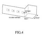
- FIG. 4is a diagram illustrating an antenna, which is hidden in a communication system supporting a BDMA scheme, according to an embodiment of the present invention
- FIG. 5is a graph illustrating a value of a reflection coefficient according to an antenna, which is hidden in a communication system supporting a BDMA scheme, according to an embodiment of the present invention
- FIG. 8Ais a graph illustrating a value of a reflection coefficient according to a degree in which an antenna array is hidden, shown schematically in FIG. 8B , in a communication system supporting a BDMA scheme, according to an embodiment of the present invention
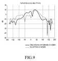
- FIG. 9is a graph illustrating a change of a beam pattern according to a degree in which an array antenna is hidden in a communication system supporting a BDMA scheme, according to an embodiment of the present invention.
- FIGS. 10A-10Care diagrams illustrating a process of determining whether antenna elements are operable in a communication system supporting a BDMA scheme, according to an embodiment of the present invention
- FIG. 11is a graph illustrating an example of a method of recovering a beam using antenna elements which are operating normally in a communication system supporting a BDMA scheme, according to an embodiment of the present invention.
- FIG. 12is a diagram illustrating another example of a method of recovering a beam using antenna elements which are operating normally in a communication system supporting a BDMA scheme, according to an embodiment of the present invention.
- ordinal numberssuch as “first,” “second,” and so forth will be used to describe various components, those components are not limited herein. The terms are used only for distinguishing one component from another component. For example, a first component may be referred to as a second component and likewise, a second component may also be referred to as a first component, without departing from the teaching of the inventive concept.
- the term “and/or” used hereinincludes any and all combinations of one or more of the associated listed items.
- an electronic devicemay include communication functionality.
- an electronic devicemay be a smart phone, a tablet personal computer (PC), a mobile phone, a video phone, an e-book reader, a desktop PC, a laptop PC, a netbook PC, a personal digital assistant (PDA), a portable multimedia player (PMP), an mp3 player, a mobile medical device, a camera, a wearable device (e.g., a head-mounted device (HMD), electronic clothes, electronic braces, an electronic necklace, an electronic appcessory, an electronic tattoo, or a smart watch), and/or the like.
- a wearable devicee.g., a head-mounted device (HMD), electronic clothes, electronic braces, an electronic necklace, an electronic appcessory, an electronic tattoo, or a smart watch
- the electronic devicemay be a smart home appliance with communication functionality.
- a smart home appliancemay be, for example, a television, a digital video disk (DVD) player, an audio, a refrigerator, an air conditioner, a vacuum cleaner, an oven, a microwave oven, a washer, a dryer, an air purifier, a set-top box, a TV box (e.g., Samsung HomeSync®, Apple TV®, or Google TV®), a gaining console, an electronic dictionary, an electronic key, a camcorder, an electronic picture frame, and/or the like.
- DVDdigital video disk
- the electronic devicemay be a medical device (e.g., magnetic resonance angiography (MRA) device, a magnetic resonance imaging (MRI) device, computed tomography (CT) device, an imaging device, or an ultrasonic device), a navigation device, a global positioning system (GPS) receiver, an event data recorder (EDR), a flight data recorder (FDR), an automotive infotainment device, a naval electronic device (e.g., naval navigation device, gyroscope, or compass), an avionic electronic device, a security device, an industrial or consumer robot, and/or the like.
- MRAmagnetic resonance angiography
- MRImagnetic resonance imaging
- CTcomputed tomography
- ultrasonic deviceultrasonic device
- GPSglobal positioning system
- EDRevent data recorder
- FDRflight data recorder
- automotive infotainment devicee.g., a navigation device, a global positioning system (GPS) receiver, an event data recorder (EDR), a flight data
- the electronic devicemay be furniture, part of a building/structure, an electronic board, electronic signature receiving device, a projector, various measuring devices (e.g., water, electricity, gas or electro-magnetic wave measuring devices), and/or the like that include communication functionality.
- various measuring devicese.g., water, electricity, gas or electro-magnetic wave measuring devices
- the electronic devicemay be any combination of the foregoing devices.
- the electronic deviceis not limited to the foregoing devices.
- a portable terminalmay be the electronic device described herein.
- FIG. 1is a diagram illustrating a beam pattern adjusting apparatus in a communication system supporting a BDMA scheme, according to an embodiment of the present invention.
- the beam pattern adjusting apparatus 100is implemented in a portable terminal 101 , and the portable terminal 100 includes an antenna array including at least two antenna elements.
- the portable terminal 100is in contact with a user's body, e.g., a hand of a user, and the beam pattern adjusting apparatus may be impedance matched by considering an electromagnetic characteristic due to the user's body in a relatively high frequency band, e.g., a frequency band which is greater than or equal to 10 GHz.
- FIG. 2is diagram illustrating an inner structure of a beam pattern adjusting apparatus in a communication system supporting a BDMA scheme, according to an embodiment of the present invention.
- the beam pattern adjusting apparatus 100includes a plurality of antennas, e.g., N antennas, i.e., an antenna#1 211 - 1 , an antenna#2 211 - 2 , . . . , an antenna#N 211 -N, and N adjusters, i.e., an adjuster#1 213 - 1 , . . . , an adjuster#N 213 -N which are connected to the N antennas, a controller 215 , and a detector 217 .
- the antenna#1 211 - 1 , the antenna#2 211 - 2 , . . . , the antenna#N 211 -Nare included in one antenna array. That is, each of the antenna#1 211 - 1 , the antenna#2 211 - 2 , . . . , the antenna#N 211 -N is an antenna element included in the antenna array.
- the controller 215controls the overall operation of the beam pattern adjusting apparatus 100 . More particularly, the controller 215 detects a degree in which a part of a user's body, such as a hand, a head, etc. is close to a specific antenna of the antenna array based on a VSWR signal, which is received from each of the N antennas, and determines whether the specific antenna is operating normally. The controller 215 detects a magnitude of a signal and a phase of a signal included in a VSWR signal for each of remaining antennas except for the specific antenna from among the N antennas. The controller 215 controls the overall operation of the beam pattern adjusting apparatus 100 , which will be described in greater detail with reference to FIGS. 3-12 .
- the detector 217detects a VSWR signal, which is reflected from each of the N antennas.
- Each of the N adjustersincludes an amplifier and a phase shifter. That is, the adjuster#1 213 - 1 includes a phase shifter#1 219 - 1 and an amplifier#1 221 - 1 . In this way, the adjuster#N 213 -N as the last adjuster includes a phase shifter#N 219 -N and an amplifier#N 221 -N.
- the antenna#1 211 - 1 , the antenna#2 211 - 2 , . . . , the antenna#N 211 -N, the adjuster#1 213 - 1 , . . . , the adjuster#N 213 -N, the controller 215 , and the detector 217are described as separate units, it is to be understood that this is merely for convenience of description.
- two or more of the antenna#1 211 - 1 , the antenna#2 211 - 2 , . . . , the antenna#N 211 -N, the adjuster#1 213 - 1 , . . . , the adjuster#N 213 -N, the controller 215 , and the detector 217may be incorporated into a single unit, such as on a System of Chip (SoC).
- SoCSystem of Chip
- the beam pattern adjusting apparatus 100may be implemented as one processor.
- a method of the beam pattern adjusting apparatus 100 in a communication system supporting a BDMA scheme, according to an embodiment of the present invention,will be described with reference to FIG. 3 .
- the beam pattern adjusting apparatus 100detects a VSWR change value for each of the antennas included in the antenna array, at step 311 .
- the reason the VSWR change value for each of antenna elements is detectedis that the beam pattern adjusting apparatus detects a degree in which an antenna of the antenna array is hidden, e.g., blocked or concealed by another object, such as a user's hand, based on the VSWR change value.
- the beam pattern adjusting apparatus 100determines whether the VSWR change value for each of the antennas is greater than or equal to a threshold VSWR change value, at step 313 .
- the reason for determining whether the VSWR change value for each of the antenna elements is greater than or equal to the threshold VSWR change valueis that the beam pattern adjusting apparatus detects a degree in which an antenna of the antenna array or the antenna array is hidden by an external factor. A situation in which an antenna is hidden will be described in greater detail with reference to FIGS. 4-9 .
- the beam pattern adjusting apparatus 100proceeds to step 317 . If the VSWR change value for each of the antennas is less than the threshold VSWR change value, an antenna hidden situation for the antenna array is not present.
- the beam pattern adjusting apparatus 100determines that an antenna of which a VSWR change value is greater than or equal to the threshold VSWR change value from among the antenna elements is not operating normally, the beam adjusting apparatus 100 stops running a related antenna, and selects another antenna from among the antenna array. That is, the beam pattern adjusting apparatus 100 replaces the related antenna, which is stopped, with the another antenna.
- a situation in which an antenna is hiddenmay be detected according to a height and a distance of an object. For example, if a distance between an antenna and an object is shorter than about 0.05 ⁇ , and a height of the object is higher than about 0.1 ⁇ , the situation in which an antenna is hidden may be detected.
- FIG. 5is a graph illustrating a value of a reflection coefficient according to an antenna, which is hidden in a communication system supporting a BDMA scheme, according to an embodiment of the present invention.
- the reflection coefficient value graphscorresponds to an instance where a portable terminal includes a 1 ⁇ 4 antenna array.
- the reflection coefficient value graphcorresponds to an instance where a single antenna among the four antennas included in the 1 ⁇ 4 antenna array is hidden.
- a value of a reflection coefficient according to a distance between an antenna array and a part of a user's body in a communication system supporting a BDMA scheme, according to an embodiment of the present invention,will be described with reference to FIGS. 7A and 7B .
- FIG. 7Ais a graph illustrating a value of a reflection coefficient according to a distance between an antenna array and a user's body, shown schematically in FIG. 7B , in a communication system supporting a BDMA scheme, according to an embodiment of the present invention.
- FIG. 8Ais a graph illustrating a value of a reflection coefficient according to a degree in which an antenna array is hidden, shown schematically in FIG. 8B , in a communication system supporting a BDMA scheme, according to an embodiment of the present invention.
- a change of a beam pattern according to a degree in which an antenna array is hidden in a communication system supporting a BDMA scheme, according to an embodiment of the present invention,will be described with reference to FIG. 9 .
- FIG. 9indicates a change of a beam pattern in an instance where a 1 ⁇ 4 array antenna is used in the communication system supporting the BDMA scheme, an antenna element#2 from among four antennas included in the 1 ⁇ 4 antenna array is completely hidden by an external factor, and a beam direction is 30° in a ⁇ direction.
- the beam pattern adjusting apparatus 100While using four antennas from among the eight antennas, i.e., the antenna element#1, the antenna element#2, the antenna element#3, and the antenna element#4 ( FIG. 10A ), the beam pattern adjusting apparatus 100 detects that the antenna element#1, the antenna element#1′′, the antenna element#2, and the antenna element#4′′ are unable to operate due to an external factor, e.g., a body part of a user, ( FIG. 10B ). In this instance, the beam pattern adjusting apparatus 100 detects the remaining operable antennas and selects the antenna element#2′′ and the antenna element#3′′, and stops an operation of the antenna element#1 ( FIG. 10C ).
- FIG. 11is a graph illustrating an example of a method of recovering a beam using antenna elements which are operating normally in a communication system supporting a BDMA scheme, according to an embodiment of the present invention.
- the beam pattern adjusting apparatus 100may amplify or attenuate a signal for some RF chains to maintain gain or inhibit a side lobe.
- FIG. 12Another example of a process of recovering a beam using antenna elements which are operating normally in a communication system supporting a BDMA scheme, according to an embodiment of the present invention, will be described with reference to FIG. 12 .
- the beam pattern adjusting apparatus 100may amplify or attenuate a signal for the some RF chains to maintain gain or inhibit a side lobe.
- the beam pattern adjusting apparatus 100is effective in various antenna array environments such as a BDMA scheme.
- the beam pattern adjusting apparatus 100When using the beam pattern adjusting apparatus 100 in a BDMA scheme, it is relatively easy to detect an effect that a part of a user's body has on an antenna array included in a portable terminal, thereby obtaining the best performance from the antenna array.
- a method and apparatusmay be implemented by hardware, software and/or a combination thereof.
- the softwaremay be stored in a non-volatile storage, for example, an erasable or re-writable ROM, a memory, for example, a RAM, a memory chip, a memory device, or a memory integrated circuit (IC), or an optically or magnetically recordable non-transitory machine-readable (e.g., computer-readable), storage medium (e.g., a compact disk (CD), a digital versatile disk (DVD), a magnetic disk, a magnetic tape, and/or the like).
- a non-volatile storagefor example, an erasable or re-writable ROM, a memory, for example, a RAM, a memory chip, a memory device, or a memory integrated circuit (IC), or an optically or magnetically recordable non-transitory machine-readable (e.g., computer-readable), storage medium (e.g., a compact disk (CD),
- a method and apparatus according to an embodiment of the present inventionmay be implemented by a computer or a mobile terminal that includes a controller and a memory, and the memory may be an example of a non-transitory machine-readable (e.g., computer-readable), storage medium suitable to store a program or programs including instructions for implementing various embodiments of the present invention.
- a computer or a mobile terminalthat includes a controller and a memory
- the memorymay be an example of a non-transitory machine-readable (e.g., computer-readable), storage medium suitable to store a program or programs including instructions for implementing various embodiments of the present invention.
- An apparatusmay receive the program from a program providing device which is connected to the apparatus via a wire or a wireless and store the program.
- the program providing devicemay include a memory for storing instructions which instruct to perform a content protect method which has been already installed, information necessary for the content protect method, and the like, a communication unit for performing a wired or a wireless communication with a graphic processing device, and a controller for transmitting a related program to a transmitting/receiving device based on a request of the graphic processing device or automatically transmitting the related program to the transmitting/receiving device.
Landscapes
- Engineering & Computer Science (AREA)
- Computer Networks & Wireless Communication (AREA)
- Signal Processing (AREA)
- Power Engineering (AREA)
- Physics & Mathematics (AREA)
- Electromagnetism (AREA)
- Radio Transmission System (AREA)
Abstract
Description
Claims (20)
Applications Claiming Priority (2)
| Application Number | Priority Date | Filing Date | Title |
|---|---|---|---|
| KR10-2014-0052744 | 2014-04-30 | ||
| KR1020140052744AKR102112003B1 (en) | 2014-04-30 | 2014-04-30 | Apparatus and method for adjusting beam pattern in communication system supporting beam division multiple access scheme |
Publications (2)
| Publication Number | Publication Date |
|---|---|
| US20150318610A1 US20150318610A1 (en) | 2015-11-05 |
| US9461360B2true US9461360B2 (en) | 2016-10-04 |
Family
ID=54355893
Family Applications (1)
| Application Number | Title | Priority Date | Filing Date |
|---|---|---|---|
| US14/701,117ActiveUS9461360B2 (en) | 2014-04-30 | 2015-04-30 | Apparatus and method for adjusting beam pattern in communication system supporting beam division multiple access scheme |
Country Status (2)
| Country | Link |
|---|---|
| US (1) | US9461360B2 (en) |
| KR (1) | KR102112003B1 (en) |
Families Citing this family (173)
| Publication number | Priority date | Publication date | Assignee | Title |
|---|---|---|---|---|
| US10209771B2 (en) | 2016-09-30 | 2019-02-19 | Sony Interactive Entertainment Inc. | Predictive RF beamforming for head mounted display |
| US10009065B2 (en) | 2012-12-05 | 2018-06-26 | At&T Intellectual Property I, L.P. | Backhaul link for distributed antenna system |
| US9113347B2 (en) | 2012-12-05 | 2015-08-18 | At&T Intellectual Property I, Lp | Backhaul link for distributed antenna system |
| US9999038B2 (en) | 2013-05-31 | 2018-06-12 | At&T Intellectual Property I, L.P. | Remote distributed antenna system |
| US9525524B2 (en) | 2013-05-31 | 2016-12-20 | At&T Intellectual Property I, L.P. | Remote distributed antenna system |
| US8897697B1 (en) | 2013-11-06 | 2014-11-25 | At&T Intellectual Property I, Lp | Millimeter-wave surface-wave communications |
| US9209902B2 (en) | 2013-12-10 | 2015-12-08 | At&T Intellectual Property I, L.P. | Quasi-optical coupler |
| US9692101B2 (en) | 2014-08-26 | 2017-06-27 | At&T Intellectual Property I, L.P. | Guided wave couplers for coupling electromagnetic waves between a waveguide surface and a surface of a wire |
| US9768833B2 (en) | 2014-09-15 | 2017-09-19 | At&T Intellectual Property I, L.P. | Method and apparatus for sensing a condition in a transmission medium of electromagnetic waves |
| US10063280B2 (en) | 2014-09-17 | 2018-08-28 | At&T Intellectual Property I, L.P. | Monitoring and mitigating conditions in a communication network |
| US9628854B2 (en) | 2014-09-29 | 2017-04-18 | At&T Intellectual Property I, L.P. | Method and apparatus for distributing content in a communication network |
| US9615269B2 (en) | 2014-10-02 | 2017-04-04 | At&T Intellectual Property I, L.P. | Method and apparatus that provides fault tolerance in a communication network |
| US9685992B2 (en) | 2014-10-03 | 2017-06-20 | At&T Intellectual Property I, L.P. | Circuit panel network and methods thereof |
| US9503189B2 (en) | 2014-10-10 | 2016-11-22 | At&T Intellectual Property I, L.P. | Method and apparatus for arranging communication sessions in a communication system |
| US9762289B2 (en) | 2014-10-14 | 2017-09-12 | At&T Intellectual Property I, L.P. | Method and apparatus for transmitting or receiving signals in a transportation system |
| US9973299B2 (en) | 2014-10-14 | 2018-05-15 | At&T Intellectual Property I, L.P. | Method and apparatus for adjusting a mode of communication in a communication network |
| US9769020B2 (en) | 2014-10-21 | 2017-09-19 | At&T Intellectual Property I, L.P. | Method and apparatus for responding to events affecting communications in a communication network |
| US9312919B1 (en) | 2014-10-21 | 2016-04-12 | At&T Intellectual Property I, Lp | Transmission device with impairment compensation and methods for use therewith |
| US9780834B2 (en) | 2014-10-21 | 2017-10-03 | At&T Intellectual Property I, L.P. | Method and apparatus for transmitting electromagnetic waves |
| US9627768B2 (en) | 2014-10-21 | 2017-04-18 | At&T Intellectual Property I, L.P. | Guided-wave transmission device with non-fundamental mode propagation and methods for use therewith |
| US9564947B2 (en) | 2014-10-21 | 2017-02-07 | At&T Intellectual Property I, L.P. | Guided-wave transmission device with diversity and methods for use therewith |
| US9520945B2 (en) | 2014-10-21 | 2016-12-13 | At&T Intellectual Property I, L.P. | Apparatus for providing communication services and methods thereof |
| US9653770B2 (en) | 2014-10-21 | 2017-05-16 | At&T Intellectual Property I, L.P. | Guided wave coupler, coupling module and methods for use therewith |
| US9577306B2 (en) | 2014-10-21 | 2017-02-21 | At&T Intellectual Property I, L.P. | Guided-wave transmission device and methods for use therewith |
| US9742462B2 (en) | 2014-12-04 | 2017-08-22 | At&T Intellectual Property I, L.P. | Transmission medium and communication interfaces and methods for use therewith |
| US9680670B2 (en) | 2014-11-20 | 2017-06-13 | At&T Intellectual Property I, L.P. | Transmission device with channel equalization and control and methods for use therewith |
| US10009067B2 (en) | 2014-12-04 | 2018-06-26 | At&T Intellectual Property I, L.P. | Method and apparatus for configuring a communication interface |
| US9654173B2 (en) | 2014-11-20 | 2017-05-16 | At&T Intellectual Property I, L.P. | Apparatus for powering a communication device and methods thereof |
| US10243784B2 (en) | 2014-11-20 | 2019-03-26 | At&T Intellectual Property I, L.P. | System for generating topology information and methods thereof |
| US9954287B2 (en) | 2014-11-20 | 2018-04-24 | At&T Intellectual Property I, L.P. | Apparatus for converting wireless signals and electromagnetic waves and methods thereof |
| US9461706B1 (en) | 2015-07-31 | 2016-10-04 | At&T Intellectual Property I, Lp | Method and apparatus for exchanging communication signals |
| US9800327B2 (en) | 2014-11-20 | 2017-10-24 | At&T Intellectual Property I, L.P. | Apparatus for controlling operations of a communication device and methods thereof |
| US10340573B2 (en) | 2016-10-26 | 2019-07-02 | At&T Intellectual Property I, L.P. | Launcher with cylindrical coupling device and methods for use therewith |
| US9997819B2 (en) | 2015-06-09 | 2018-06-12 | At&T Intellectual Property I, L.P. | Transmission medium and method for facilitating propagation of electromagnetic waves via a core |
| US9544006B2 (en) | 2014-11-20 | 2017-01-10 | At&T Intellectual Property I, L.P. | Transmission device with mode division multiplexing and methods for use therewith |
| US10144036B2 (en) | 2015-01-30 | 2018-12-04 | At&T Intellectual Property I, L.P. | Method and apparatus for mitigating interference affecting a propagation of electromagnetic waves guided by a transmission medium |
| US9876570B2 (en) | 2015-02-20 | 2018-01-23 | At&T Intellectual Property I, Lp | Guided-wave transmission device with non-fundamental mode propagation and methods for use therewith |
| US9749013B2 (en) | 2015-03-17 | 2017-08-29 | At&T Intellectual Property I, L.P. | Method and apparatus for reducing attenuation of electromagnetic waves guided by a transmission medium |
| US9705561B2 (en) | 2015-04-24 | 2017-07-11 | At&T Intellectual Property I, L.P. | Directional coupling device and methods for use therewith |
| US10224981B2 (en) | 2015-04-24 | 2019-03-05 | At&T Intellectual Property I, Lp | Passive electrical coupling device and methods for use therewith |
| US9948354B2 (en) | 2015-04-28 | 2018-04-17 | At&T Intellectual Property I, L.P. | Magnetic coupling device with reflective plate and methods for use therewith |
| US9793954B2 (en) | 2015-04-28 | 2017-10-17 | At&T Intellectual Property I, L.P. | Magnetic coupling device and methods for use therewith |
| US9871282B2 (en) | 2015-05-14 | 2018-01-16 | At&T Intellectual Property I, L.P. | At least one transmission medium having a dielectric surface that is covered at least in part by a second dielectric |
| US9490869B1 (en) | 2015-05-14 | 2016-11-08 | At&T Intellectual Property I, L.P. | Transmission medium having multiple cores and methods for use therewith |
| US9748626B2 (en) | 2015-05-14 | 2017-08-29 | At&T Intellectual Property I, L.P. | Plurality of cables having different cross-sectional shapes which are bundled together to form a transmission medium |
| US10650940B2 (en) | 2015-05-15 | 2020-05-12 | At&T Intellectual Property I, L.P. | Transmission medium having a conductive material and methods for use therewith |
| US10679767B2 (en) | 2015-05-15 | 2020-06-09 | At&T Intellectual Property I, L.P. | Transmission medium having a conductive material and methods for use therewith |
| US9917341B2 (en) | 2015-05-27 | 2018-03-13 | At&T Intellectual Property I, L.P. | Apparatus and method for launching electromagnetic waves and for modifying radial dimensions of the propagating electromagnetic waves |
| US9912381B2 (en) | 2015-06-03 | 2018-03-06 | At&T Intellectual Property I, Lp | Network termination and methods for use therewith |
| US10348391B2 (en) | 2015-06-03 | 2019-07-09 | At&T Intellectual Property I, L.P. | Client node device with frequency conversion and methods for use therewith |
| US10154493B2 (en) | 2015-06-03 | 2018-12-11 | At&T Intellectual Property I, L.P. | Network termination and methods for use therewith |
| US9866309B2 (en) | 2015-06-03 | 2018-01-09 | At&T Intellectual Property I, Lp | Host node device and methods for use therewith |
| US10103801B2 (en) | 2015-06-03 | 2018-10-16 | At&T Intellectual Property I, L.P. | Host node device and methods for use therewith |
| US10812174B2 (en) | 2015-06-03 | 2020-10-20 | At&T Intellectual Property I, L.P. | Client node device and methods for use therewith |
| US9913139B2 (en) | 2015-06-09 | 2018-03-06 | At&T Intellectual Property I, L.P. | Signal fingerprinting for authentication of communicating devices |
| JP2017005514A (en)* | 2015-06-10 | 2017-01-05 | 富士通株式会社 | Radio equipment |
| US10142086B2 (en) | 2015-06-11 | 2018-11-27 | At&T Intellectual Property I, L.P. | Repeater and methods for use therewith |
| US9608692B2 (en) | 2015-06-11 | 2017-03-28 | At&T Intellectual Property I, L.P. | Repeater and methods for use therewith |
| US9820146B2 (en) | 2015-06-12 | 2017-11-14 | At&T Intellectual Property I, L.P. | Method and apparatus for authentication and identity management of communicating devices |
| US9667317B2 (en) | 2015-06-15 | 2017-05-30 | At&T Intellectual Property I, L.P. | Method and apparatus for providing security using network traffic adjustments |
| US9865911B2 (en) | 2015-06-25 | 2018-01-09 | At&T Intellectual Property I, L.P. | Waveguide system for slot radiating first electromagnetic waves that are combined into a non-fundamental wave mode second electromagnetic wave on a transmission medium |
| US9640850B2 (en) | 2015-06-25 | 2017-05-02 | At&T Intellectual Property I, L.P. | Methods and apparatus for inducing a non-fundamental wave mode on a transmission medium |
| US9509415B1 (en) | 2015-06-25 | 2016-11-29 | At&T Intellectual Property I, L.P. | Methods and apparatus for inducing a fundamental wave mode on a transmission medium |
| US10170840B2 (en) | 2015-07-14 | 2019-01-01 | At&T Intellectual Property I, L.P. | Apparatus and methods for sending or receiving electromagnetic signals |
| US9882257B2 (en) | 2015-07-14 | 2018-01-30 | At&T Intellectual Property I, L.P. | Method and apparatus for launching a wave mode that mitigates interference |
| US10341142B2 (en) | 2015-07-14 | 2019-07-02 | At&T Intellectual Property I, L.P. | Apparatus and methods for generating non-interfering electromagnetic waves on an uninsulated conductor |
| US9836957B2 (en) | 2015-07-14 | 2017-12-05 | At&T Intellectual Property I, L.P. | Method and apparatus for communicating with premises equipment |
| US10320586B2 (en) | 2015-07-14 | 2019-06-11 | At&T Intellectual Property I, L.P. | Apparatus and methods for generating non-interfering electromagnetic waves on an insulated transmission medium |
| US10033108B2 (en) | 2015-07-14 | 2018-07-24 | At&T Intellectual Property I, L.P. | Apparatus and methods for generating an electromagnetic wave having a wave mode that mitigates interference |
| US9722318B2 (en) | 2015-07-14 | 2017-08-01 | At&T Intellectual Property I, L.P. | Method and apparatus for coupling an antenna to a device |
| US10205655B2 (en) | 2015-07-14 | 2019-02-12 | At&T Intellectual Property I, L.P. | Apparatus and methods for communicating utilizing an antenna array and multiple communication paths |
| US10044409B2 (en) | 2015-07-14 | 2018-08-07 | At&T Intellectual Property I, L.P. | Transmission medium and methods for use therewith |
| US9847566B2 (en) | 2015-07-14 | 2017-12-19 | At&T Intellectual Property I, L.P. | Method and apparatus for adjusting a field of a signal to mitigate interference |
| US9853342B2 (en) | 2015-07-14 | 2017-12-26 | At&T Intellectual Property I, L.P. | Dielectric transmission medium connector and methods for use therewith |
| US9628116B2 (en) | 2015-07-14 | 2017-04-18 | At&T Intellectual Property I, L.P. | Apparatus and methods for transmitting wireless signals |
| US10033107B2 (en) | 2015-07-14 | 2018-07-24 | At&T Intellectual Property I, L.P. | Method and apparatus for coupling an antenna to a device |
| US10148016B2 (en) | 2015-07-14 | 2018-12-04 | At&T Intellectual Property I, L.P. | Apparatus and methods for communicating utilizing an antenna array |
| US9608740B2 (en) | 2015-07-15 | 2017-03-28 | At&T Intellectual Property I, L.P. | Method and apparatus for launching a wave mode that mitigates interference |
| US10090606B2 (en)* | 2015-07-15 | 2018-10-02 | At&T Intellectual Property I, L.P. | Antenna system with dielectric array and methods for use therewith |
| US9793951B2 (en) | 2015-07-15 | 2017-10-17 | At&T Intellectual Property I, L.P. | Method and apparatus for launching a wave mode that mitigates interference |
| US9871283B2 (en) | 2015-07-23 | 2018-01-16 | At&T Intellectual Property I, Lp | Transmission medium having a dielectric core comprised of plural members connected by a ball and socket configuration |
| US9749053B2 (en) | 2015-07-23 | 2017-08-29 | At&T Intellectual Property I, L.P. | Node device, repeater and methods for use therewith |
| US9948333B2 (en) | 2015-07-23 | 2018-04-17 | At&T Intellectual Property I, L.P. | Method and apparatus for wireless communications to mitigate interference |
| US9912027B2 (en) | 2015-07-23 | 2018-03-06 | At&T Intellectual Property I, L.P. | Method and apparatus for exchanging communication signals |
| US10784670B2 (en) | 2015-07-23 | 2020-09-22 | At&T Intellectual Property I, L.P. | Antenna support for aligning an antenna |
| US9735833B2 (en) | 2015-07-31 | 2017-08-15 | At&T Intellectual Property I, L.P. | Method and apparatus for communications management in a neighborhood network |
| US10020587B2 (en) | 2015-07-31 | 2018-07-10 | At&T Intellectual Property I, L.P. | Radial antenna and methods for use therewith |
| US9967173B2 (en) | 2015-07-31 | 2018-05-08 | At&T Intellectual Property I, L.P. | Method and apparatus for authentication and identity management of communicating devices |
| US9904535B2 (en) | 2015-09-14 | 2018-02-27 | At&T Intellectual Property I, L.P. | Method and apparatus for distributing software |
| US10079661B2 (en) | 2015-09-16 | 2018-09-18 | At&T Intellectual Property I, L.P. | Method and apparatus for use with a radio distributed antenna system having a clock reference |
| US10136434B2 (en) | 2015-09-16 | 2018-11-20 | At&T Intellectual Property I, L.P. | Method and apparatus for use with a radio distributed antenna system having an ultra-wideband control channel |
| US10009901B2 (en) | 2015-09-16 | 2018-06-26 | At&T Intellectual Property I, L.P. | Method, apparatus, and computer-readable storage medium for managing utilization of wireless resources between base stations |
| US9705571B2 (en) | 2015-09-16 | 2017-07-11 | At&T Intellectual Property I, L.P. | Method and apparatus for use with a radio distributed antenna system |
| US10009063B2 (en) | 2015-09-16 | 2018-06-26 | At&T Intellectual Property I, L.P. | Method and apparatus for use with a radio distributed antenna system having an out-of-band reference signal |
| US10051629B2 (en) | 2015-09-16 | 2018-08-14 | At&T Intellectual Property I, L.P. | Method and apparatus for use with a radio distributed antenna system having an in-band reference signal |
| US9769128B2 (en) | 2015-09-28 | 2017-09-19 | At&T Intellectual Property I, L.P. | Method and apparatus for encryption of communications over a network |
| US9729197B2 (en) | 2015-10-01 | 2017-08-08 | At&T Intellectual Property I, L.P. | Method and apparatus for communicating network management traffic over a network |
| US9876264B2 (en) | 2015-10-02 | 2018-01-23 | At&T Intellectual Property I, Lp | Communication system, guided wave switch and methods for use therewith |
| US10074890B2 (en) | 2015-10-02 | 2018-09-11 | At&T Intellectual Property I, L.P. | Communication device and antenna with integrated light assembly |
| US9882277B2 (en) | 2015-10-02 | 2018-01-30 | At&T Intellectual Property I, Lp | Communication device and antenna assembly with actuated gimbal mount |
| US10355367B2 (en) | 2015-10-16 | 2019-07-16 | At&T Intellectual Property I, L.P. | Antenna structure for exchanging wireless signals |
| US10665942B2 (en) | 2015-10-16 | 2020-05-26 | At&T Intellectual Property I, L.P. | Method and apparatus for adjusting wireless communications |
| US10051483B2 (en) | 2015-10-16 | 2018-08-14 | At&T Intellectual Property I, L.P. | Method and apparatus for directing wireless signals |
| US9912419B1 (en) | 2016-08-24 | 2018-03-06 | At&T Intellectual Property I, L.P. | Method and apparatus for managing a fault in a distributed antenna system |
| US9860075B1 (en) | 2016-08-26 | 2018-01-02 | At&T Intellectual Property I, L.P. | Method and communication node for broadband distribution |
| US10291311B2 (en) | 2016-09-09 | 2019-05-14 | At&T Intellectual Property I, L.P. | Method and apparatus for mitigating a fault in a distributed antenna system |
| US11032819B2 (en) | 2016-09-15 | 2021-06-08 | At&T Intellectual Property I, L.P. | Method and apparatus for use with a radio distributed antenna system having a control channel reference signal |
| US10340600B2 (en) | 2016-10-18 | 2019-07-02 | At&T Intellectual Property I, L.P. | Apparatus and methods for launching guided waves via plural waveguide systems |
| US10135146B2 (en) | 2016-10-18 | 2018-11-20 | At&T Intellectual Property I, L.P. | Apparatus and methods for launching guided waves via circuits |
| US10135147B2 (en) | 2016-10-18 | 2018-11-20 | At&T Intellectual Property I, L.P. | Apparatus and methods for launching guided waves via an antenna |
| US10811767B2 (en) | 2016-10-21 | 2020-10-20 | At&T Intellectual Property I, L.P. | System and dielectric antenna with convex dielectric radome |
| US9991580B2 (en) | 2016-10-21 | 2018-06-05 | At&T Intellectual Property I, L.P. | Launcher and coupling system for guided wave mode cancellation |
| US9876605B1 (en) | 2016-10-21 | 2018-01-23 | At&T Intellectual Property I, L.P. | Launcher and coupling system to support desired guided wave mode |
| US10374316B2 (en) | 2016-10-21 | 2019-08-06 | At&T Intellectual Property I, L.P. | System and dielectric antenna with non-uniform dielectric |
| US10312567B2 (en) | 2016-10-26 | 2019-06-04 | At&T Intellectual Property I, L.P. | Launcher with planar strip antenna and methods for use therewith |
| US10225025B2 (en) | 2016-11-03 | 2019-03-05 | At&T Intellectual Property I, L.P. | Method and apparatus for detecting a fault in a communication system |
| US10291334B2 (en) | 2016-11-03 | 2019-05-14 | At&T Intellectual Property I, L.P. | System for detecting a fault in a communication system |
| US10498044B2 (en) | 2016-11-03 | 2019-12-03 | At&T Intellectual Property I, L.P. | Apparatus for configuring a surface of an antenna |
| US10224634B2 (en) | 2016-11-03 | 2019-03-05 | At&T Intellectual Property I, L.P. | Methods and apparatus for adjusting an operational characteristic of an antenna |
| US10340601B2 (en) | 2016-11-23 | 2019-07-02 | At&T Intellectual Property I, L.P. | Multi-antenna system and methods for use therewith |
| US10340603B2 (en) | 2016-11-23 | 2019-07-02 | At&T Intellectual Property I, L.P. | Antenna system having shielded structural configurations for assembly |
| US10178445B2 (en) | 2016-11-23 | 2019-01-08 | At&T Intellectual Property I, L.P. | Methods, devices, and systems for load balancing between a plurality of waveguides |
| US10090594B2 (en) | 2016-11-23 | 2018-10-02 | At&T Intellectual Property I, L.P. | Antenna system having structural configurations for assembly |
| US10535928B2 (en) | 2016-11-23 | 2020-01-14 | At&T Intellectual Property I, L.P. | Antenna system and methods for use therewith |
| US10305190B2 (en) | 2016-12-01 | 2019-05-28 | At&T Intellectual Property I, L.P. | Reflecting dielectric antenna system and methods for use therewith |
| US10361489B2 (en) | 2016-12-01 | 2019-07-23 | At&T Intellectual Property I, L.P. | Dielectric dish antenna system and methods for use therewith |
| US10755542B2 (en) | 2016-12-06 | 2020-08-25 | At&T Intellectual Property I, L.P. | Method and apparatus for surveillance via guided wave communication |
| US10694379B2 (en) | 2016-12-06 | 2020-06-23 | At&T Intellectual Property I, L.P. | Waveguide system with device-based authentication and methods for use therewith |
| US10020844B2 (en) | 2016-12-06 | 2018-07-10 | T&T Intellectual Property I, L.P. | Method and apparatus for broadcast communication via guided waves |
| US10135145B2 (en) | 2016-12-06 | 2018-11-20 | At&T Intellectual Property I, L.P. | Apparatus and methods for generating an electromagnetic wave along a transmission medium |
| US10382976B2 (en) | 2016-12-06 | 2019-08-13 | At&T Intellectual Property I, L.P. | Method and apparatus for managing wireless communications based on communication paths and network device positions |
| US10727599B2 (en) | 2016-12-06 | 2020-07-28 | At&T Intellectual Property I, L.P. | Launcher with slot antenna and methods for use therewith |
| US10637149B2 (en) | 2016-12-06 | 2020-04-28 | At&T Intellectual Property I, L.P. | Injection molded dielectric antenna and methods for use therewith |
| US10439675B2 (en) | 2016-12-06 | 2019-10-08 | At&T Intellectual Property I, L.P. | Method and apparatus for repeating guided wave communication signals |
| US10819035B2 (en) | 2016-12-06 | 2020-10-27 | At&T Intellectual Property I, L.P. | Launcher with helical antenna and methods for use therewith |
| US9927517B1 (en) | 2016-12-06 | 2018-03-27 | At&T Intellectual Property I, L.P. | Apparatus and methods for sensing rainfall |
| US10326494B2 (en) | 2016-12-06 | 2019-06-18 | At&T Intellectual Property I, L.P. | Apparatus for measurement de-embedding and methods for use therewith |
| US10359749B2 (en) | 2016-12-07 | 2019-07-23 | At&T Intellectual Property I, L.P. | Method and apparatus for utilities management via guided wave communication |
| US10168695B2 (en) | 2016-12-07 | 2019-01-01 | At&T Intellectual Property I, L.P. | Method and apparatus for controlling an unmanned aircraft |
| US10446936B2 (en) | 2016-12-07 | 2019-10-15 | At&T Intellectual Property I, L.P. | Multi-feed dielectric antenna system and methods for use therewith |
| US9893795B1 (en) | 2016-12-07 | 2018-02-13 | At&T Intellectual Property I, Lp | Method and repeater for broadband distribution |
| US10139820B2 (en) | 2016-12-07 | 2018-11-27 | At&T Intellectual Property I, L.P. | Method and apparatus for deploying equipment of a communication system |
| US10389029B2 (en) | 2016-12-07 | 2019-08-20 | At&T Intellectual Property I, L.P. | Multi-feed dielectric antenna system with core selection and methods for use therewith |
| US10547348B2 (en) | 2016-12-07 | 2020-01-28 | At&T Intellectual Property I, L.P. | Method and apparatus for switching transmission mediums in a communication system |
| US10027397B2 (en) | 2016-12-07 | 2018-07-17 | At&T Intellectual Property I, L.P. | Distributed antenna system and methods for use therewith |
| US10243270B2 (en) | 2016-12-07 | 2019-03-26 | At&T Intellectual Property I, L.P. | Beam adaptive multi-feed dielectric antenna system and methods for use therewith |
| US10777873B2 (en) | 2016-12-08 | 2020-09-15 | At&T Intellectual Property I, L.P. | Method and apparatus for mounting network devices |
| US9998870B1 (en) | 2016-12-08 | 2018-06-12 | At&T Intellectual Property I, L.P. | Method and apparatus for proximity sensing |
| US10530505B2 (en) | 2016-12-08 | 2020-01-07 | At&T Intellectual Property I, L.P. | Apparatus and methods for launching electromagnetic waves along a transmission medium |
| US10411356B2 (en) | 2016-12-08 | 2019-09-10 | At&T Intellectual Property I, L.P. | Apparatus and methods for selectively targeting communication devices with an antenna array |
| US10389037B2 (en) | 2016-12-08 | 2019-08-20 | At&T Intellectual Property I, L.P. | Apparatus and methods for selecting sections of an antenna array and use therewith |
| US10938108B2 (en) | 2016-12-08 | 2021-03-02 | At&T Intellectual Property I, L.P. | Frequency selective multi-feed dielectric antenna system and methods for use therewith |
| US10326689B2 (en) | 2016-12-08 | 2019-06-18 | At&T Intellectual Property I, L.P. | Method and system for providing alternative communication paths |
| US9911020B1 (en) | 2016-12-08 | 2018-03-06 | At&T Intellectual Property I, L.P. | Method and apparatus for tracking via a radio frequency identification device |
| US10601494B2 (en) | 2016-12-08 | 2020-03-24 | At&T Intellectual Property I, L.P. | Dual-band communication device and method for use therewith |
| US10916969B2 (en) | 2016-12-08 | 2021-02-09 | At&T Intellectual Property I, L.P. | Method and apparatus for providing power using an inductive coupling |
| US10069535B2 (en) | 2016-12-08 | 2018-09-04 | At&T Intellectual Property I, L.P. | Apparatus and methods for launching electromagnetic waves having a certain electric field structure |
| US10103422B2 (en) | 2016-12-08 | 2018-10-16 | At&T Intellectual Property I, L.P. | Method and apparatus for mounting network devices |
| US10340983B2 (en) | 2016-12-09 | 2019-07-02 | At&T Intellectual Property I, L.P. | Method and apparatus for surveying remote sites via guided wave communications |
| US10264586B2 (en) | 2016-12-09 | 2019-04-16 | At&T Mobility Ii Llc | Cloud-based packet controller and methods for use therewith |
| US9838896B1 (en) | 2016-12-09 | 2017-12-05 | At&T Intellectual Property I, L.P. | Method and apparatus for assessing network coverage |
| US9973940B1 (en) | 2017-02-27 | 2018-05-15 | At&T Intellectual Property I, L.P. | Apparatus and methods for dynamic impedance matching of a guided wave launcher |
| US10298293B2 (en) | 2017-03-13 | 2019-05-21 | At&T Intellectual Property I, L.P. | Apparatus of communication utilizing wireless network devices |
| WO2020162645A1 (en)* | 2019-02-07 | 2020-08-13 | 엘지전자 주식회사 | Electronic device comprising antenna |
| US11343681B1 (en)* | 2019-07-08 | 2022-05-24 | T-Mobile Innovations Llc | Dynamic beam management of an antenna array with a faulty element |
| CN113950773A (en)* | 2019-09-27 | 2022-01-18 | 谷歌有限责任公司 | Proximity detection using calculated voltage standing wave ratio readings |
| FI129860B (en) | 2020-04-29 | 2022-10-14 | Elisa Oyj | Handling vswr value or the like of antennas in telecommunication networks |
| US11050475B1 (en)* | 2020-06-17 | 2021-06-29 | Verizon Patent And Licensing Inc. | Systems and methods for mapping Remote Electrical Tilt components and antenna ports of a cellular tower based on return loss associated with antennas of the cellular tower |
| CN112730997B (en)* | 2020-12-23 | 2024-03-12 | 昆山锐诚达电子有限公司 | Automatic detection method for 5G rod sleeve antenna |
| US20250180636A1 (en)* | 2022-02-11 | 2025-06-05 | Georgia Tech Research Corporation | Current and voltage sensing based voltage-standing-wave-ratio impedance and power detector and method |
| US20240097324A1 (en)* | 2022-09-16 | 2024-03-21 | Apple Inc. | Electronic Devices with Dynamic Antenna Switching |
| US12407101B2 (en)* | 2022-09-21 | 2025-09-02 | Qualcomm Incorporated | Antenna impedance detection and tuning |
| US20250039807A1 (en)* | 2023-07-27 | 2025-01-30 | Qualcomm Incorporated | Coherent uplink mimo |
Citations (4)
| Publication number | Priority date | Publication date | Assignee | Title |
|---|---|---|---|---|
| US5412414A (en) | 1988-04-08 | 1995-05-02 | Martin Marietta Corporation | Self monitoring/calibrating phased array radar and an interchangeable, adjustable transmit/receive sub-assembly |
| US20070149146A1 (en) | 2005-12-14 | 2007-06-28 | Samsung Electronics Co., Ltd. | Apparatus for automatically matching frequency of antenna in wireless terminal and method of using the same |
| US20120051409A1 (en)* | 2010-09-01 | 2012-03-01 | Samsung Electronics Co., Ltd. | Apparatus and method for controlling a tunable matching network in a wireless network |
| US20130271342A1 (en)* | 2010-12-29 | 2013-10-17 | Zte Corporation | Device and method for antenna impedance matching |
Family Cites Families (3)
| Publication number | Priority date | Publication date | Assignee | Title |
|---|---|---|---|---|
| JP3281917B2 (en)* | 1999-08-11 | 2002-05-13 | 独立行政法人通信総合研究所 | Antenna device |
| US6765530B1 (en)* | 2002-07-16 | 2004-07-20 | Ball Aerospace & Technologies Corp. | Array antenna having pairs of antenna elements |
| JP5917119B2 (en)* | 2011-12-09 | 2016-05-11 | スタッフ株式会社 | Broadband small antenna |
- 2014
- 2014-04-30KRKR1020140052744Apatent/KR102112003B1/enactiveActive
- 2015
- 2015-04-30USUS14/701,117patent/US9461360B2/enactiveActive
Patent Citations (4)
| Publication number | Priority date | Publication date | Assignee | Title |
|---|---|---|---|---|
| US5412414A (en) | 1988-04-08 | 1995-05-02 | Martin Marietta Corporation | Self monitoring/calibrating phased array radar and an interchangeable, adjustable transmit/receive sub-assembly |
| US20070149146A1 (en) | 2005-12-14 | 2007-06-28 | Samsung Electronics Co., Ltd. | Apparatus for automatically matching frequency of antenna in wireless terminal and method of using the same |
| US20120051409A1 (en)* | 2010-09-01 | 2012-03-01 | Samsung Electronics Co., Ltd. | Apparatus and method for controlling a tunable matching network in a wireless network |
| US20130271342A1 (en)* | 2010-12-29 | 2013-10-17 | Zte Corporation | Device and method for antenna impedance matching |
Also Published As
| Publication number | Publication date |
|---|---|
| KR20150125401A (en) | 2015-11-09 |
| KR102112003B1 (en) | 2020-05-18 |
| US20150318610A1 (en) | 2015-11-05 |
Similar Documents
| Publication | Publication Date | Title |
|---|---|---|
| US9461360B2 (en) | Apparatus and method for adjusting beam pattern in communication system supporting beam division multiple access scheme | |
| US11316253B2 (en) | Electronic device comprising antenna | |
| US11296416B2 (en) | Metamaterial structure antenna and metamaterial structure array | |
| CN111279668B (en) | Electronic device comprising an antenna | |
| US10547108B2 (en) | Antenna device and electronic device including the same | |
| CN107851885B (en) | Antenna device and electronic device including the same | |
| US10666327B2 (en) | Electronic device and method for correcting phase in electronic device | |
| KR102178485B1 (en) | Antenna and electronic device having it | |
| CN112117538A (en) | Electronic device that selects an antenna that supports a given radio communication among multiple antennas | |
| US11139564B2 (en) | Electronic device including antenna | |
| US10128561B2 (en) | Antenna apparatus and electronic device including the same | |
| CN105633547A (en) | Antenna and electronic device including the same | |
| US9635443B2 (en) | Frequency division duplex wireless communication apparatus and method | |
| US10951071B2 (en) | Wireless charging system for using frequency control | |
| US10044112B2 (en) | Variable antenna and apparatus for detecting radio signal | |
| US20160277044A1 (en) | Electronic device and method of controlling transmission power | |
| US20160056535A1 (en) | Multiband antenna | |
| US11196151B2 (en) | Electronic device comprising antenna | |
| US11424554B2 (en) | Antenna device | |
| US20160378705A1 (en) | Electronic device and method for controlling signal strength according to mode | |
| KR20180121067A (en) | Method of outputing signal using an anttena disposed adjacent to a conductive member of a connector and an electronic device using the same | |
| CN115963335A (en) | Test system, chassis shielding effectiveness test method, test equipment and storage medium | |
| US12235379B2 (en) | Electronic device and method for detecting external object by using antenna array | |
| CN101304277B (en) | Method and apparatus for acquiring intelligent antenna channel characteristics | |
| US11133783B2 (en) | Power amplifier and impedance adjustment circuit |
Legal Events
| Date | Code | Title | Description |
|---|---|---|---|
| AS | Assignment | Owner name:SAMSUNG ELECTRONICS CO., LTD., KOREA, REPUBLIC OF Free format text:ASSIGNMENT OF ASSIGNORS INTEREST;ASSIGNORS:LEE, WON-SEOK;KIM, YONG-HOON;OH, KYOUNG-SUB;AND OTHERS;REEL/FRAME:035712/0332 Effective date:20150430 Owner name:KOREA ADVANCED INSTITUTE OF SCIENCE AND TECHNOLOGY Free format text:ASSIGNMENT OF ASSIGNORS INTEREST;ASSIGNORS:LEE, WON-SEOK;KIM, YONG-HOON;OH, KYOUNG-SUB;AND OTHERS;REEL/FRAME:035712/0332 Effective date:20150430 | |
| FEPP | Fee payment procedure | Free format text:PAYOR NUMBER ASSIGNED (ORIGINAL EVENT CODE: ASPN); ENTITY STATUS OF PATENT OWNER: LARGE ENTITY | |
| STCF | Information on status: patent grant | Free format text:PATENTED CASE | |
| MAFP | Maintenance fee payment | Free format text:PAYMENT OF MAINTENANCE FEE, 4TH YEAR, LARGE ENTITY (ORIGINAL EVENT CODE: M1551); ENTITY STATUS OF PATENT OWNER: LARGE ENTITY Year of fee payment:4 | |
| MAFP | Maintenance fee payment | Free format text:PAYMENT OF MAINTENANCE FEE, 8TH YEAR, LARGE ENTITY (ORIGINAL EVENT CODE: M1552); ENTITY STATUS OF PATENT OWNER: LARGE ENTITY Year of fee payment:8 |