US9459469B2 - System for contact lens wireless communication - Google Patents
System for contact lens wireless communicationDownload PDFInfo
- Publication number
- US9459469B2 US9459469B2US14/668,957US201514668957AUS9459469B2US 9459469 B2US9459469 B2US 9459469B2US 201514668957 AUS201514668957 AUS 201514668957AUS 9459469 B2US9459469 B2US 9459469B2
- Authority
- US
- United States
- Prior art keywords
- contact lens
- wireless communication
- communication device
- external storage
- antenna
- Prior art date
- Legal status (The legal status is an assumption and is not a legal conclusion. Google has not performed a legal analysis and makes no representation as to the accuracy of the status listed.)
- Active - Reinstated
Links
- 238000004891communicationMethods0.000titleclaimsdescription59
- 239000012530fluidSubstances0.000claimsabstractdescription24
- 238000003860storageMethods0.000claimsdescription12
- 238000000034methodMethods0.000claimsdescription6
- FAPWRFPIFSIZLT-UHFFFAOYSA-MSodium chlorideChemical compound[Na+].[Cl-]FAPWRFPIFSIZLT-UHFFFAOYSA-M0.000claimsdescription5
- 230000005540biological transmissionEffects0.000abstractdescription11
- 238000012546transferMethods0.000abstractdescription9
- 238000012937correctionMethods0.000abstractdescription8
- 238000005516engineering processMethods0.000abstractdescription3
- 239000000017hydrogelSubstances0.000description10
- 229920001296polysiloxanePolymers0.000description10
- 239000002243precursorSubstances0.000description7
- 239000003990capacitorSubstances0.000description6
- 239000000463materialSubstances0.000description5
- 239000000203mixtureSubstances0.000description5
- 230000008901benefitEffects0.000description3
- 238000010586diagramMethods0.000description3
- 239000011780sodium chlorideSubstances0.000description3
- XLOMVQKBTHCTTD-UHFFFAOYSA-NZinc monoxideChemical compound[Zn]=OXLOMVQKBTHCTTD-UHFFFAOYSA-N0.000description2
- 230000004397blinkingEffects0.000description2
- 239000000919ceramicSubstances0.000description2
- 230000001960triggered effectEffects0.000description2
- XLYOFNOQVPJJNP-UHFFFAOYSA-NwaterSubstancesOXLYOFNOQVPJJNP-UHFFFAOYSA-N0.000description2
- PSBDWGZCVUAZQS-UHFFFAOYSA-N(dimethylsulfonio)acetateChemical compoundC[S+](C)CC([O-])=OPSBDWGZCVUAZQS-UHFFFAOYSA-N0.000description1
- ZGTMUACCHSMWAC-UHFFFAOYSA-LEDTA disodium salt (anhydrous)Chemical compound[Na+].[Na+].OC(=O)CN(CC([O-])=O)CCN(CC(O)=O)CC([O-])=OZGTMUACCHSMWAC-UHFFFAOYSA-L0.000description1
- 239000002033PVDF binderSubstances0.000description1
- 229920001090Polyaminopropyl biguanidePolymers0.000description1
- 239000004642PolyimideSubstances0.000description1
- 229920000289PolyquaterniumPolymers0.000description1
- 229920001486SU-8 photoresistPolymers0.000description1
- 108010067390Viral ProteinsProteins0.000description1
- 239000007864aqueous solutionSubstances0.000description1
- 229910002113barium titanateInorganic materials0.000description1
- JRPBQTZRNDNNOP-UHFFFAOYSA-Nbarium titanateChemical compound[Ba+2].[Ba+2].[O-][Ti]([O-])([O-])[O-]JRPBQTZRNDNNOP-UHFFFAOYSA-N0.000description1
- 210000000988bone and boneAnatomy0.000description1
- 229910021538boraxInorganic materials0.000description1
- KGBXLFKZBHKPEV-UHFFFAOYSA-Nboric acidChemical compoundOB(O)OKGBXLFKZBHKPEV-UHFFFAOYSA-N0.000description1
- 239000004327boric acidSubstances0.000description1
- 210000004556brainAnatomy0.000description1
- 230000001413cellular effectEffects0.000description1
- 239000013078crystalSubstances0.000description1
- 210000003298dental enamelAnatomy0.000description1
- 210000004268dentinAnatomy0.000description1
- 239000000645desinfectantSubstances0.000description1
- NKZSPGSOXYXWQA-UHFFFAOYSA-Ndioxido(oxo)titanium;lead(2+)Chemical compound[Pb+2].[O-][Ti]([O-])=ONKZSPGSOXYXWQA-UHFFFAOYSA-N0.000description1
- 239000003814drugSubstances0.000description1
- 230000009977dual effectEffects0.000description1
- 229940124274edetate disodiumDrugs0.000description1
- 230000005672electromagnetic fieldEffects0.000description1
- 230000005686electrostatic fieldEffects0.000description1
- 238000000605extractionMethods0.000description1
- 239000011521glassSubstances0.000description1
- 238000003306harvestingMethods0.000description1
- KIUKXJAPPMFGSW-MNSSHETKSA-NhyaluronanChemical compoundCC(=O)N[C@H]1[C@H](O)O[C@H](CO)[C@@H](O)C1O[C@H]1[C@H](O)[C@@H](O)[C@H](O[C@H]2[C@@H](C(O[C@H]3[C@@H]([C@@H](O)[C@H](O)[C@H](O3)C(O)=O)O)[C@H](O)[C@@H](CO)O2)NC(C)=O)[C@@H](C(O)=O)O1KIUKXJAPPMFGSW-MNSSHETKSA-N0.000description1
- 229940099552hyaluronanDrugs0.000description1
- 229920002674hyaluronanPolymers0.000description1
- 230000008676importEffects0.000description1
- 239000000644isotonic solutionSubstances0.000description1
- 229910052451lead zirconate titanateInorganic materials0.000description1
- HFGPZNIAWCZYJU-UHFFFAOYSA-Nlead zirconate titanateChemical compound[O-2].[O-2].[O-2].[O-2].[O-2].[Ti+4].[Zr+4].[Pb+2]HFGPZNIAWCZYJU-UHFFFAOYSA-N0.000description1
- 229910052744lithiumInorganic materials0.000description1
- GQYHUHYESMUTHG-UHFFFAOYSA-Nlithium niobateChemical compound[Li+].[O-][Nb](=O)=OGQYHUHYESMUTHG-UHFFFAOYSA-N0.000description1
- 244000144972livestockSpecies0.000description1
- 238000004519manufacturing processMethods0.000description1
- 229910052751metalInorganic materials0.000description1
- 239000002184metalSubstances0.000description1
- 150000002739metalsChemical class0.000description1
- 238000012986modificationMethods0.000description1
- 230000004048modificationEffects0.000description1
- 229920001987poloxaminePolymers0.000description1
- 229920000052poly(p-xylylene)Polymers0.000description1
- 229920003223poly(pyromellitimide-1,4-diphenyl ether)Polymers0.000description1
- 229940093424polyaminopropyl biguanideDrugs0.000description1
- 229920001721polyimidePolymers0.000description1
- 229920000642polymerPolymers0.000description1
- 238000006116polymerization reactionMethods0.000description1
- 229920002981polyvinylidene fluoridePolymers0.000description1
- UKDIAJWKFXFVFG-UHFFFAOYSA-Npotassium;oxido(dioxo)niobiumChemical compound[K+].[O-][Nb](=O)=OUKDIAJWKFXFVFG-UHFFFAOYSA-N0.000description1
- 230000005855radiationEffects0.000description1
- 208000014733refractive errorDiseases0.000description1
- 238000012827research and developmentMethods0.000description1
- 230000004044responseEffects0.000description1
- 235000010339sodium tetraborateNutrition0.000description1
- XMVONEAAOPAGAO-UHFFFAOYSA-Nsodium tungstateChemical compound[Na+].[Na+].[O-][W]([O-])(=O)=OXMVONEAAOPAGAO-UHFFFAOYSA-N0.000description1
- 239000000243solutionSubstances0.000description1
- 238000004659sterilization and disinfectionMethods0.000description1
- 229940117986sulfobetaineDrugs0.000description1
- 210000002435tendonAnatomy0.000description1
- 239000012780transparent materialSubstances0.000description1
- BSVBQGMMJUBVOD-UHFFFAOYSA-Ntrisodium borateChemical compound[Na+].[Na+].[Na+].[O-]B([O-])[O-]BSVBQGMMJUBVOD-UHFFFAOYSA-N0.000description1
- 241001515965unidentified phageSpecies0.000description1
- 239000002023woodSubstances0.000description1
- 239000011787zinc oxideSubstances0.000description1
Images


Classifications
- G—PHYSICS
- G02—OPTICS
- G02C—SPECTACLES; SUNGLASSES OR GOGGLES INSOFAR AS THEY HAVE THE SAME FEATURES AS SPECTACLES; CONTACT LENSES
- G02C7/00—Optical parts
- G02C7/02—Lenses; Lens systems ; Methods of designing lenses
- G02C7/04—Contact lenses for the eyes
- A—HUMAN NECESSITIES
- A45—HAND OR TRAVELLING ARTICLES
- A45C—PURSES; LUGGAGE; HAND CARRIED BAGS
- A45C11/00—Receptacles for purposes not provided for in groups A45C1/00-A45C9/00
- A45C11/005—Contact lens cases
- G—PHYSICS
- G02—OPTICS
- G02C—SPECTACLES; SUNGLASSES OR GOGGLES INSOFAR AS THEY HAVE THE SAME FEATURES AS SPECTACLES; CONTACT LENSES
- G02C11/00—Non-optical adjuncts; Attachment thereof
- G02C11/10—Electronic devices other than hearing aids
Definitions
- This inventionrelates generally to wireless communication with a contact lens, and more particularly, to a system and method for transferring data from a contact lens using radio frequencies.
- Wireless transmission of datavaries greatly, from one-way broadcast systems such as radio and television signals to two way systems such as Wi-Fi and cellular signals.
- One type of wireless transmission, radio-frequency identification, or RFIDutilizes electromagnetic or electrostatic fields to transfer data.
- An RFID deviceutilizes an antenna and a transceiver to read the radio frequency and transfer information to an external device, and a transponder, or tag, which contains the circuitry of the RFID and the data to be transmitted.
- RFIDis advantageous over other types of wireless transmission in that it does not require a power source to transmit data. Consequently, RFID transmission is limited to a short range and limited data transfer. As such, RFID is most commonly used for automatically identifying and tracking tags attached to objects, such as clothing, livestock, pets, assembly lines, pharmaceuticals, etc. Powered RFID systems can solve many of the unpowered RFID shortcomings by increasing range and reduced interference.
- the human eyein very simplistic terms, is adapted to provide vision by detecting and converting light into electrical impulses for the brain. While the human eye is extremely intricate and precise, the image produced often needs correction.
- the most common type of vision correctionincludes glasses and/or contact lenses, which are used to improve vision by correcting refractive error. This is done by directly focusing the light so that it enters the eye with the proper intensity.
- the present inventionwill provide a vision correction device which makes use of wireless transmissions and/or wireless charging to transfer data between the vision correction device and an external device. More specifically, the present invention will incorporate radio frequency technology onto a contact lens, including passive and active embodiments, and may further include wireless charging capability. This is accomplished by positioning an extremely small RF device onto a contact lens, along with an antenna and/or battery, and using a fluid medium to enhance the signal to and from an external device.
- the RF deviceWhen in use, the RF device is adapted to provide identifying information, such as which batch a lens is from and when it was manufactured. Furthermore, the RF device is adapted to notify the user when it is time to dispose of the contact lens, either from time or usage statistics. The RFID device will transmit this information either passively or actively to an external device, providing the user with invaluable information relating to their vision. The RF device can further communicate charging information such as charging states, charging rate, and other relevant information when wireless charging is used.
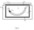
- FIG. 1is a diagram illustrating the wireless communication device and contact lens within an external device
- FIG. 2is a diagram illustrating the antenna, microprocessor, and power source of the contact lens within an external device
- FIG. 3is a diagram illustrating the method of using the present invention.
- the present inventioncomprises one or a plurality of contact lenses 20 , a wireless communication device 30 , an antenna assembly 40 , 41 , a fluid medium 50 , and an external device 60 . More specifically, the wireless communication device 30 and the antenna assembly 40 , 41 are positioned on the external device 60 , while the external device 60 is not in in physical contact with the contact lens 20 , but is in fluid contact with the contact lens 20 through the fluid medium 50 . When in use, the wireless communication device 30 is adapted to interact with the antenna assembly 40 , 41 to communicate with the external device 60 through the fluid medium 50 .
- the wireless communication device 30may be read-only, having a unique key or data sequence, or may be read/write, where data can be written into the wireless communication device 30 .
- the wireless communication device 30is positioned on the outer edge of the contact lens 20 and is adapted to send and/or receive wireless data to/from the external device 60 through the fluid medium 50 .
- the wireless communication device 30is a passive tag RFID device. More specifically, the wireless communication device 30 is a passive tag RFID device adapted to operate without a power source 31 . The wireless communication device 30 is activated when a signal is received from the external device 60 . The signal will power the passive RFID device, which will then begin transmitting data. Advantages of a passive tag RFID device include a smaller size and no power requirements, which are paramount with dealing with contact lenses.
- an active tag RFID (powered) deviceis used.
- a small battery or capacitor 31is positioned on the outer edge of the contact lens 20 in electrical communication with the wireless communication device 30 and operates to provide power for transmitting data through the wireless communication device 30 .
- Advantages of an active tag RFID deviceinclude longer ranges, improved response time, less interference, and lower radiation.
- the wireless communication device 30is adapted to charge a battery or capacitor 31 used for powering a microprocessor chip 32 .
- the wireless communication device 30will receive radio frequencies from the external device 60 , convert these radio frequencies into electrical energy, and store this electrical energy in the capacitor or battery 31 . The energy requirements are low, however, and said battery or capacitor 31 may be easily charged wirelessly in this manner.
- the antenna assembly 40 , 41operates to receive data and other radio frequencies, as well as facilitate the transfer of data between the wireless communication device 30 and the external device 60 .
- a first, or top, antenna 40is positioned in the cap 61
- a second, or bottom, antenna 41is positioned in the external device 60 adjacent to the fluid chamber 62 .
- a lens antenna 33is positioned on the perimeter of the contact lens 20 in electrical communication with the wireless communication device 30 , outside of the view of the user. In all embodiment, the lens antenna 33 , as well as the wireless communication device 30 and/or battery 31 , will not be visible by the user.
- the antennasis adapted to amplify signals send and received greatly, as these signals are used to activate the wireless communication device 30 .
- the fluid medium 50 between the contact lens 20 and the external device 60operates to amplify the RF signals from 1-10 times.
- the fluid medium 50also acts as a disinfectant and improves surface wetablility and comfort of the contact lenses 20 during storage in the external device 60 .
- the fluid medium 50may be saline water.
- the fluid medium 21is a sterile, isotonic solution further comprising hyaluronan, sulfobetaine, poloxamine, boric acid, sodium borate, edetate disodium and sodium chloride and preserved with a dual disinfection system comprising polyaminopropyl biguanide and polyquaternium.
- the fluid mediumcomprises an electrical conductivity between 1.6 to 22.2 siemens per meter, a saline concentration between 1% to 25% of the overall solution, and will have a volume between 2.5 mm 2 to 10 mm 2 .
- the external device 60is used to transmit data and/or power to the contact lens 20 .
- the external device 60is a contact lens case further comprising a cap 61 and fluid chamber 62 , where the contact lens 20 may be stored for 1-8 hours daily. Due to the long storage periods, the external device 60 and contact lens 20 may transmit data and energy even at low transfer speeds or energy levels. For example, data collected during use can be transferred from a microprocessor 32 in the contact lens 20 to the external device 60 at extremely low speeds. Also, energy can be transferred from the external device 60 to the battery or capacitor 32 for wireless charging, thus enabling the external device 60 to operate as a power outlet.
- miscellaneous informationsuch as identification numbers (RFID), logged usage data, and user data (blinking, light exposure) can be transmitted from the contact lens 20 to the external device 60 during this time.
- RFIDidentification numbers
- the present inventionmay monitor time used and count usage cycles to notify the user when the contact lens 20 needs replacement or care.
- the external device 60will further comprise an antenna assembly 40 , 41 to communicate with the contact lens 20 with less interference, both for data and wireless charging, and the external device 60 will enclose the contact lens 20 in a fluid chamber 62 , further reducing interference and increasing the reliability of the transmission.
- the wireless communication device 30When in use, the wireless communication device 30 will receive a message from the external device 60 , or an interrogation message, once it is in range. In the passive embodiment, the signal strength of the interrogation message will activate the wireless communication device 30 . The wireless communication device 30 will authenticate this interrogation message and will respond with identification or other data once authenticated. Alternatively, with an active Tag RFID, the wireless communication device 30 will broadcast an interrogation message, where the external device 60 will receive the message for authentication. In a further alternative embodiment, the interrogation message will operate to wake the wireless communication device 30 from a sleeping state, which will then begin to transmit data with the external device 60 once authenticated.
- the wireless communication device 30is adapted to fit on the perimeter of a contact lens 20 .
- the size of the wireless communication device 30will be within the range of 0.05 mm ⁇ 0.05 mm.
- the wireless communicationwill operate in a frequency range of 10 kHz-100 MHz.
- the wireless communication device 30is adapted to communicate at a range of 1 cm-1 m.
- the frequency rangeincreases to 10 kHz-5 GHz, with a range of 1 cm-100 m.
- a piezoelectric sensoris used to receive a frequency within a specific range for data transmission or wireless charging.
- the piezoelectric sensoris sensitive enough to distinguish frequencies, and is adapted to receive only frequencies which can communicate with the wireless communication device 30 .
- the piezoelectric sensormay comprise synthetic piezoelectric ceramics including, but not limited to, barium titanate, lead titanate, lead zirconate titanate, potassium niobate, lithium niobate, lithium tantalite, sodium tungstate, and zinc oxide.
- the piezoelectric sensormay comprise a polymer piezoelectric such as polyvinylidene fluoride.
- biological piezoelectricscan be used including bone, tendon, silk, wood, enamel, dentin, DNA, and viral protein such as bacteriophage.
- a vibration sensormay be implemented to activate the wireless communication device 30 .
- a battery 31 or a piezoelectric sensoris adapted to produce an electrical charge when the vibrational sensor is triggered.
- the vibration sensorcan be triggered when the contact lens 20 is removed from the eye or removed from the external device 60 . Once a vibration, or lack thereof, is sensed, the vibrational sensor will activate the wireless communication device 30 .
- the present inventionmay be paired with a piezoelectric energy harvesting device for powering the wireless communication device 30 and/or vibration sensor.
- Energycan be harvested from the movement of the eye, blinking, body movement, or other source.
- a battery or capacitor 31may be provided to receive and store this energy.
- the userWhen in use, the user will place a contact lens 20 within an external storage device 60 .
- An interrogation messagewill be received from the external device 60 , which is then authenticated within the contact lens 20 .
- wireless data transmission and/or wireless chargingmay begin between the contact lens 20 and external device 60 . This communication and/or charging may last between 2-8 hours, providing ample time for charging and information transfer.
- the present inventionis manufactured such that the components work in conjunction to provide data transmission and/or wireless charging with an external storage device 60 .
- the method of manufacturing the present inventioncomprises first electrically connecting the wireless communication device 30 with any microprocessors 32 , antennas 33 , and/or power sources 31 , creating a wireless communication circuit.
- any transparent materialsmay be used to reduce obstructing the vision of the user.
- a contact lens mold memberpreferably the female mold member, or first (anterior) contact lens mold member.
- the placementwould occur preferably robotically and be coupled with a means of centering the assembly and a means of controlling the depth of the assembly during the filling of the mold with a lens precursor material, which can be understood to be a polymerizable silicone hydrogel lens precursor composition.
- the polymerizable silicone hydrogel lens precursor compositionmay be understood to be a pre-polymerized or pre-cured composition suitable for polymerization.
- the lens precursor materialmay be comprised of silicone, hydrogel, polyimide, kapton, parylene, or SU-8.
- Non-stretchable lens precursor materialscomprise metals, ceramics, and crystals.
- the first contact lens mold memberis placed in contact with a second contact lens mold member to form a contact lens mold having a contact lens shaped cavity.
- the two contact lens mold membersare placed in contact with one another to form a contact lens shaped cavity, with the polymerizable silicone hydrogel lens precursor composition and wireless communication circuit positioned within the contact lens shaped cavity.
- the polymerizable silicone hydrogel lens precursor compositionis then cured to form a pre-extracted polymerized silicone hydrogel contact lens product.
- the contact lens moldis then demolded, where the two mold members are separated.
- the pre-extracted polymerized silicone hydrogel contact lens productis then separated from the contact lens mold members, or delensed. After delensing, the pre-extracted silicone hydrogel contact lens product is extracted. After extraction, the extracted polymerized silicone hydrogel contact lens product is hydrated with water or an aqueous solution to form a hydrated silicone hydrogel contact lens.
Landscapes
- Physics & Mathematics (AREA)
- Health & Medical Sciences (AREA)
- Ophthalmology & Optometry (AREA)
- General Health & Medical Sciences (AREA)
- General Physics & Mathematics (AREA)
- Optics & Photonics (AREA)
- Eyeglasses (AREA)
- Engineering & Computer Science (AREA)
- Signal Processing (AREA)
- Acoustics & Sound (AREA)
- Otolaryngology (AREA)
Abstract
Description
Claims (11)
Priority Applications (1)
| Application Number | Priority Date | Filing Date | Title |
|---|---|---|---|
| US14/668,957US9459469B2 (en) | 2014-03-25 | 2015-03-25 | System for contact lens wireless communication |
Applications Claiming Priority (2)
| Application Number | Priority Date | Filing Date | Title |
|---|---|---|---|
| US201461970335P | 2014-03-25 | 2014-03-25 | |
| US14/668,957US9459469B2 (en) | 2014-03-25 | 2015-03-25 | System for contact lens wireless communication |
Publications (2)
| Publication Number | Publication Date |
|---|---|
| US20150281411A1 US20150281411A1 (en) | 2015-10-01 |
| US9459469B2true US9459469B2 (en) | 2016-10-04 |
Family
ID=54192091
Family Applications (1)
| Application Number | Title | Priority Date | Filing Date |
|---|---|---|---|
| US14/668,957Active - ReinstatedUS9459469B2 (en) | 2014-03-25 | 2015-03-25 | System for contact lens wireless communication |
Country Status (3)
| Country | Link |
|---|---|
| US (1) | US9459469B2 (en) |
| EP (1) | EP3123237A4 (en) |
| WO (1) | WO2015148735A1 (en) |
Cited By (2)
| Publication number | Priority date | Publication date | Assignee | Title |
|---|---|---|---|---|
| US20170115511A1 (en)* | 2015-10-21 | 2017-04-27 | Johnson & Johnson Vision Care, Inc. | Antenna mandrel with multiple antennas |
| US10892643B2 (en) | 2018-03-14 | 2021-01-12 | International Business Machines Corporation | Facilitation of charge of and communication with an electronic device |
Families Citing this family (25)
| Publication number | Priority date | Publication date | Assignee | Title |
|---|---|---|---|---|
| US9812096B2 (en) | 2008-01-23 | 2017-11-07 | Spy Eye, Llc | Eye mounted displays and systems using eye mounted displays |
| US9993335B2 (en) | 2014-01-08 | 2018-06-12 | Spy Eye, Llc | Variable resolution eye mounted displays |
| US9599842B2 (en)* | 2014-08-21 | 2017-03-21 | Johnson & Johnson Vision Care, Inc. | Device and methods for sealing and encapsulation for biocompatible energization elements |
| TWI713712B (en)* | 2016-03-28 | 2020-12-21 | 英商古柏威順國際控股有限合夥公司 | Contact lens blister packages and related methods |
| US10389184B2 (en)* | 2016-08-31 | 2019-08-20 | Intel Corporation | Data transfer using beamed power |
| WO2018098436A1 (en) | 2016-11-28 | 2018-05-31 | Spy Eye, Llc | Unobtrusive eye mounted display |
| US10834589B2 (en)* | 2017-10-27 | 2020-11-10 | International Business Machines Corporation | Digital data transfer between devices |
| US10673414B2 (en) | 2018-02-05 | 2020-06-02 | Tectus Corporation | Adaptive tuning of a contact lens |
| US10505394B2 (en) | 2018-04-21 | 2019-12-10 | Tectus Corporation | Power generation necklaces that mitigate energy absorption in the human body |
| US10963045B2 (en) | 2018-04-25 | 2021-03-30 | International Business Machines Corporation | Smart contact lens system with cognitive analysis and aid |
| US10838239B2 (en)* | 2018-04-30 | 2020-11-17 | Tectus Corporation | Multi-coil field generation in an electronic contact lens system |
| US10895762B2 (en) | 2018-04-30 | 2021-01-19 | Tectus Corporation | Multi-coil field generation in an electronic contact lens system |
| US10790700B2 (en) | 2018-05-18 | 2020-09-29 | Tectus Corporation | Power generation necklaces with field shaping systems |
| WO2019229725A2 (en)* | 2018-06-02 | 2019-12-05 | BODDEDA, Apparao | A smart contact lens for performing wireless operations and a method of producing the same |
| US11137622B2 (en) | 2018-07-15 | 2021-10-05 | Tectus Corporation | Eye-mounted displays including embedded conductive coils |
| US10897705B2 (en) | 2018-07-19 | 2021-01-19 | Tectus Corporation | Secure communication between a contact lens and an accessory device |
| US10602513B2 (en)* | 2018-07-27 | 2020-03-24 | Tectus Corporation | Wireless communication between a contact lens and an accessory device |
| US10529107B1 (en) | 2018-09-11 | 2020-01-07 | Tectus Corporation | Projector alignment in a contact lens |
| US10838232B2 (en) | 2018-11-26 | 2020-11-17 | Tectus Corporation | Eye-mounted displays including embedded solenoids |
| US10644543B1 (en) | 2018-12-20 | 2020-05-05 | Tectus Corporation | Eye-mounted display system including a head wearable object |
| US10944290B2 (en) | 2019-08-02 | 2021-03-09 | Tectus Corporation | Headgear providing inductive coupling to a contact lens |
| WO2021062002A1 (en)* | 2019-09-26 | 2021-04-01 | Verily Life Sciences Llc | System and kit for replenishing an electrowetting ophthalmic device |
| CN115345185B (en)* | 2022-07-13 | 2025-09-05 | 西北大学 | RFID dual-tag eye movement detection method |
| WO2024041725A1 (en)* | 2022-08-23 | 2024-02-29 | Telefonaktiebolaget Lm Ericsson (Publ) | Contact lens and method thereof |
| US12313912B2 (en) | 2022-08-23 | 2025-05-27 | Tectus Corporation | Electronic contact lens data receiver circuit |
Citations (20)
| Publication number | Priority date | Publication date | Assignee | Title |
|---|---|---|---|---|
| US5555504A (en)* | 1994-06-10 | 1996-09-10 | Johnson & Johnson Vision Products, Inc. | Production line tracking and quality control system |
| US20040203478A1 (en)* | 2002-10-10 | 2004-10-14 | Scott Jeffrey Wayne | Rfid receiver apparatus and method |
| US20070200724A1 (en)* | 2006-02-28 | 2007-08-30 | Symbol Technologies, Inc. | Energy harvesting for mobile RFID readers |
| US20070274626A1 (en)* | 2006-04-18 | 2007-11-29 | Anton Sabeta | Optical Device Characterization |
| US8252605B2 (en)* | 2003-11-24 | 2012-08-28 | Siemens Healthcare Diagnostics Inc | Method and composition for stabilizing liquid reagents |
| US20130194540A1 (en)* | 2012-01-26 | 2013-08-01 | Randall Braxton Pugh | Ophthalmic lens assembly having an integrated antenna structure |
| US8628194B2 (en)* | 2009-10-13 | 2014-01-14 | Anton Sabeta | Method and system for contact lens care and compliance |
| US20140243645A1 (en)* | 2011-10-05 | 2014-08-28 | Sensimed Sa | Intraocular Pressure Measuring and/or Monitoring Device |
| US20150062533A1 (en)* | 2013-09-04 | 2015-03-05 | Johnson & Johnson Vision Care, Inc. | Ophthalmic lens system capable of communication between lenses utilizing a secondary external devicece |
| US20150087249A1 (en)* | 2013-09-23 | 2015-03-26 | Johnson & Johnson Vision Care, Inc. | Ophthalmic lens system capable of wireless communication with multiple external devices |
| US20150335420A1 (en)* | 2004-11-02 | 2015-11-26 | E-Vision Smart Optics, Inc. | Eyewear including a remote control camera |
| US20150362754A1 (en)* | 2014-06-13 | 2015-12-17 | Google Inc. | Eye-mountable device to provide automatic accommodation and method of making same |
| US20150362749A1 (en)* | 2014-06-13 | 2015-12-17 | Google Inc. | Capacitive gaze tracking for auto-accommodation in a contact lens |
| US20150362752A1 (en)* | 2014-06-13 | 2015-12-17 | Google Inc. | Flexible conductor for use within a contact lens |
| US20150362756A1 (en)* | 2014-06-13 | 2015-12-17 | Google Inc. | Apparatus, system and method for gaze tracking based on photodetection by an eye-mountable device |
| US20150362755A1 (en)* | 2014-06-13 | 2015-12-17 | Google Inc. | Failsafe operation of eye-mountable device |
| US20150362753A1 (en)* | 2014-06-13 | 2015-12-17 | Google Inc. | Method, device and system for accessing an eye-mountable device with a user interface |
| US20150362750A1 (en)* | 2014-06-13 | 2015-12-17 | Google Inc. | Contact lens with capacitive gaze tracking |
| US20150362751A1 (en)* | 2014-06-13 | 2015-12-17 | Google Inc. | Power delivery for accommodation by an eye-mountable device |
| US20150378177A1 (en)* | 2004-11-02 | 2015-12-31 | Ronald D. Blum | Flexible electro-active lens |
Family Cites Families (6)
| Publication number | Priority date | Publication date | Assignee | Title |
|---|---|---|---|---|
| US6544193B2 (en)* | 1996-09-04 | 2003-04-08 | Marcio Marc Abreu | Noninvasive measurement of chemical substances |
| US8027095B2 (en)* | 2005-10-11 | 2011-09-27 | Hand Held Products, Inc. | Control systems for adaptive lens |
| US20100259719A1 (en)* | 2006-11-22 | 2010-10-14 | Anton Sabeta | Method and System for Determining the Orientation of an Ophthalmic Lens |
| US8608310B2 (en)* | 2007-11-07 | 2013-12-17 | University Of Washington Through Its Center For Commercialization | Wireless powered contact lens with biosensor |
| GB2464981A (en)* | 2008-11-01 | 2010-05-05 | Univ Dundee | Pressure sensor for measuring intraocular pressure that can be worn on the eye. |
| US20120140167A1 (en)* | 2010-11-01 | 2012-06-07 | Pixeloptics, Inc. | Dynamic Changeable Focus Contact And Intraocular Lens |
- 2015
- 2015-03-25USUS14/668,957patent/US9459469B2/enactiveActive - Reinstated
- 2015-03-25EPEP15768969.6Apatent/EP3123237A4/ennot_activeWithdrawn
- 2015-03-25WOPCT/US2015/022591patent/WO2015148735A1/enactiveApplication Filing
Patent Citations (22)
| Publication number | Priority date | Publication date | Assignee | Title |
|---|---|---|---|---|
| US5555504A (en)* | 1994-06-10 | 1996-09-10 | Johnson & Johnson Vision Products, Inc. | Production line tracking and quality control system |
| US20040203478A1 (en)* | 2002-10-10 | 2004-10-14 | Scott Jeffrey Wayne | Rfid receiver apparatus and method |
| US8252605B2 (en)* | 2003-11-24 | 2012-08-28 | Siemens Healthcare Diagnostics Inc | Method and composition for stabilizing liquid reagents |
| US20150335420A1 (en)* | 2004-11-02 | 2015-11-26 | E-Vision Smart Optics, Inc. | Eyewear including a remote control camera |
| US20150378177A1 (en)* | 2004-11-02 | 2015-12-31 | Ronald D. Blum | Flexible electro-active lens |
| US20070200724A1 (en)* | 2006-02-28 | 2007-08-30 | Symbol Technologies, Inc. | Energy harvesting for mobile RFID readers |
| US20070274626A1 (en)* | 2006-04-18 | 2007-11-29 | Anton Sabeta | Optical Device Characterization |
| US8628194B2 (en)* | 2009-10-13 | 2014-01-14 | Anton Sabeta | Method and system for contact lens care and compliance |
| US20140243645A1 (en)* | 2011-10-05 | 2014-08-28 | Sensimed Sa | Intraocular Pressure Measuring and/or Monitoring Device |
| US20130194540A1 (en)* | 2012-01-26 | 2013-08-01 | Randall Braxton Pugh | Ophthalmic lens assembly having an integrated antenna structure |
| US8857983B2 (en)* | 2012-01-26 | 2014-10-14 | Johnson & Johnson Vision Care, Inc. | Ophthalmic lens assembly having an integrated antenna structure |
| US20140306361A1 (en)* | 2012-01-26 | 2014-10-16 | Johnson & Johnson Vision Care, Inc. | Ophthalmic lens assembly having an integrated antenna structure |
| US20150062533A1 (en)* | 2013-09-04 | 2015-03-05 | Johnson & Johnson Vision Care, Inc. | Ophthalmic lens system capable of communication between lenses utilizing a secondary external devicece |
| US20150087249A1 (en)* | 2013-09-23 | 2015-03-26 | Johnson & Johnson Vision Care, Inc. | Ophthalmic lens system capable of wireless communication with multiple external devices |
| US20150362754A1 (en)* | 2014-06-13 | 2015-12-17 | Google Inc. | Eye-mountable device to provide automatic accommodation and method of making same |
| US20150362749A1 (en)* | 2014-06-13 | 2015-12-17 | Google Inc. | Capacitive gaze tracking for auto-accommodation in a contact lens |
| US20150362752A1 (en)* | 2014-06-13 | 2015-12-17 | Google Inc. | Flexible conductor for use within a contact lens |
| US20150362756A1 (en)* | 2014-06-13 | 2015-12-17 | Google Inc. | Apparatus, system and method for gaze tracking based on photodetection by an eye-mountable device |
| US20150362755A1 (en)* | 2014-06-13 | 2015-12-17 | Google Inc. | Failsafe operation of eye-mountable device |
| US20150362753A1 (en)* | 2014-06-13 | 2015-12-17 | Google Inc. | Method, device and system for accessing an eye-mountable device with a user interface |
| US20150362750A1 (en)* | 2014-06-13 | 2015-12-17 | Google Inc. | Contact lens with capacitive gaze tracking |
| US20150362751A1 (en)* | 2014-06-13 | 2015-12-17 | Google Inc. | Power delivery for accommodation by an eye-mountable device |
Cited By (3)
| Publication number | Priority date | Publication date | Assignee | Title |
|---|---|---|---|---|
| US20170115511A1 (en)* | 2015-10-21 | 2017-04-27 | Johnson & Johnson Vision Care, Inc. | Antenna mandrel with multiple antennas |
| US9985334B2 (en)* | 2015-10-21 | 2018-05-29 | Johnson & Johnson Vision Care, Inc. | Antenna mandrel with multiple antennas |
| US10892643B2 (en) | 2018-03-14 | 2021-01-12 | International Business Machines Corporation | Facilitation of charge of and communication with an electronic device |
Also Published As
| Publication number | Publication date |
|---|---|
| EP3123237A1 (en) | 2017-02-01 |
| EP3123237A4 (en) | 2018-01-03 |
| US20150281411A1 (en) | 2015-10-01 |
| WO2015148735A1 (en) | 2015-10-01 |
Similar Documents
| Publication | Publication Date | Title |
|---|---|---|
| US9459469B2 (en) | System for contact lens wireless communication | |
| US11783157B2 (en) | Radio-frequency identification wristband with surface acoustic wave sensor | |
| US10917744B2 (en) | System for locating remote objects | |
| US10037489B2 (en) | Methods and apparatus for automatic identification wristband | |
| US7500750B2 (en) | Method and system for tracking the wearable life of an ophthalmic product | |
| JP2021045128A (en) | Companion animal health monitoring system | |
| US20060232426A1 (en) | Ophthalmic lens characterization | |
| US9801560B2 (en) | Ophthalmic lens with a neural frequency detection system | |
| JP2023514382A (en) | charging case for electronic contact lenses | |
| US20090218891A1 (en) | Method and apparatus for rfid based smart sensors | |
| US20180043646A1 (en) | Method of power transmission to contact lens and system using the same | |
| CA2921902A1 (en) | Using unique identifiers to retrieve configuration data for tag devices | |
| KR20180135694A (en) | patch type sensor module | |
| ES2749621T3 (en) | Storage case with communication and medical data acquisition capacity | |
| KR101515855B1 (en) | Implantable UHF RFID tag device with a wireless charging function | |
| Kim et al. | Wireless technologies for wearable electronics: a review | |
| CN104548351A (en) | Electrode plate recognition system for automated external defibrillator | |
| TWM416446U (en) | Implantable wireless charging health management system | |
| KR20180135673A (en) | patch type sensor module | |
| US11589807B2 (en) | Biosensor for monitoring eyedrop usage compliance | |
| Vicente et al. | NFC2BLE communications’ bridge: From flash to continuous monitoring of biological parameters | |
| CN109872810A (en) | Pacemaker postoperative nursing monitoring system | |
| EP4356831A1 (en) | Implantable device | |
| Vicente-Samper et al. | NFC2BLE Communications’ Bridge: From Flash to Continuous Monitoring of Biological Parameters | |
| KR20070110727A (en) | Encapsulated RFID Sensor Tag for In-vivo Examination |
Legal Events
| Date | Code | Title | Description |
|---|---|---|---|
| STCF | Information on status: patent grant | Free format text:PATENTED CASE | |
| AS | Assignment | Owner name:EP GLOBAL COMMUNICATIONS, INC, CALIFORNIA Free format text:ASSIGNMENT OF ASSIGNORS INTEREST;ASSIGNORS:MARKUS, DAVID T.;HAYES, MICHAEL C;REEL/FRAME:039909/0680 Effective date:20150707 | |
| AS | Assignment | Owner name:EP GLOBAL COMMUNICATIONS, INC, CALIFORNIA Free format text:ASSIGNMENT OF ASSIGNORS INTEREST;ASSIGNORS:MARKUS, DAVID T.;HAYES, MICHAEL C;REEL/FRAME:041489/0811 Effective date:20150706 | |
| FEPP | Fee payment procedure | Free format text:MAINTENANCE FEE REMINDER MAILED (ORIGINAL EVENT CODE: REM.); ENTITY STATUS OF PATENT OWNER: SMALL ENTITY | |
| LAPS | Lapse for failure to pay maintenance fees | Free format text:PATENT EXPIRED FOR FAILURE TO PAY MAINTENANCE FEES (ORIGINAL EVENT CODE: EXP.); ENTITY STATUS OF PATENT OWNER: SMALL ENTITY | |
| STCH | Information on status: patent discontinuation | Free format text:PATENT EXPIRED DUE TO NONPAYMENT OF MAINTENANCE FEES UNDER 37 CFR 1.362 | |
| FP | Lapsed due to failure to pay maintenance fee | Effective date:20201004 | |
| FEPP | Fee payment procedure | Free format text:SURCHARGE, PETITION TO ACCEPT PYMT AFTER EXP, UNINTENTIONAL. (ORIGINAL EVENT CODE: M2558); ENTITY STATUS OF PATENT OWNER: SMALL ENTITY Free format text:PETITION RELATED TO MAINTENANCE FEES GRANTED (ORIGINAL EVENT CODE: PMFG); ENTITY STATUS OF PATENT OWNER: SMALL ENTITY Free format text:PETITION RELATED TO MAINTENANCE FEES FILED (ORIGINAL EVENT CODE: PMFP); ENTITY STATUS OF PATENT OWNER: SMALL ENTITY | |
| MAFP | Maintenance fee payment | Free format text:PAYMENT OF MAINTENANCE FEE, 4TH YR, SMALL ENTITY (ORIGINAL EVENT CODE: M2551); ENTITY STATUS OF PATENT OWNER: SMALL ENTITY Year of fee payment:4 | |
| PRDP | Patent reinstated due to the acceptance of a late maintenance fee | Effective date:20210517 | |
| STCF | Information on status: patent grant | Free format text:PATENTED CASE | |
| MAFP | Maintenance fee payment | Free format text:PAYMENT OF MAINTENANCE FEE, 8TH YR, SMALL ENTITY (ORIGINAL EVENT CODE: M2552); ENTITY STATUS OF PATENT OWNER: SMALL ENTITY Year of fee payment:8 |